Embed Size (px)
Citation preview
SR-01 Rebel Star LED Assembly
Quadica Developments Inc.47 6th Concession Rd.Brantford, Ontario N3T 5L7Canada Em: [email protected]: 1-347-223-5077
For technical questions, please contact us by email at [email protected] latest version of this document can always be downloaded from our website at www.luxeonstar.com/sr-01.pdf
Document ID: SR-01Revision: Feb 10, 2015
Page 1
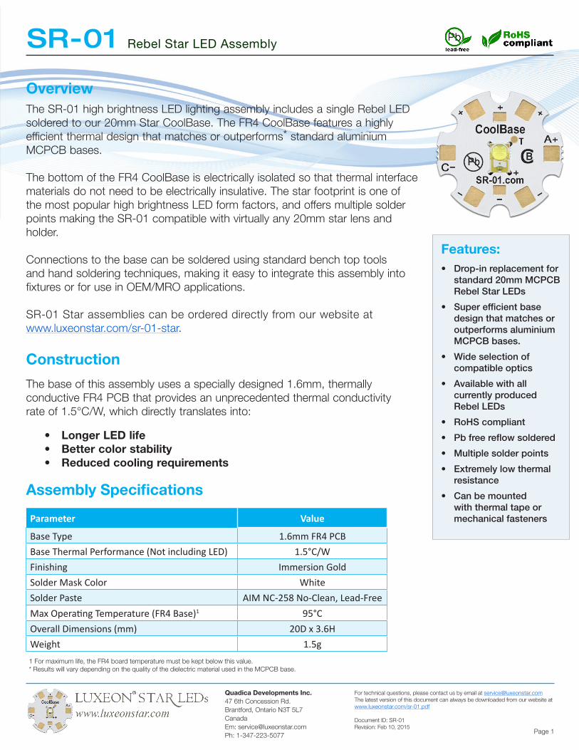
OverviewThe SR-01 high brightness LED lighting assembly includes a single Rebel LED soldered to our 20mm Star CoolBase. The FR4 CoolBase features a highly efficient thermal design that matches or outperforms* standard aluminium MCPCB bases.
The bottom of the FR4 CoolBase is electrically isolated so that thermal interface materials do not need to be electrically insulative. The star footprint is one of the most popular high brightness LED form factors, and offers multiple solder points making the SR-01 compatible with virtually any 20mm star lens and holder.
Connections to the base can be soldered using standard bench top tools and hand soldering techniques, making it easy to integrate this assembly into fixtures or for use in OEM/MRO applications.
SR-01 Star assemblies can be ordered directly from our website at www.luxeonstar.com/sr-01-star.
Construction
The base of this assembly uses a specially designed 1.6mm, thermally conductive FR4 PCB that provides an unprecedented thermal conductivity rate of 1.5°C/W, which directly translates into:
Features: • Drop-in replacement for
standard 20mm MCPCB Rebel Star LEDs
• Super efficient base design that matches or outperforms aluminium MCPCB bases.
• Wide selection of compatible optics
• Available with all currently produced Rebel LEDs
• RoHS compliant
• Pb free reflow soldered
• Multiple solder points
• Extremely low thermal resistance
• Can be mounted with thermal tape or mechanical fasteners
• Longer LED life• Better color stability• Reduced cooling requirements
Assembly Specifications
Parameter Value
Base Type 1.6mm FR4 PCBBase Thermal Performance (Not including LED) 1.5°C/WFinishing Immersion GoldSolder Mask Color WhiteSolder Paste AIM NC-258 No-Clean, Lead-FreeMax Operating Temperature (FR4 Base)1 95°COverall Dimensions (mm) 20D x 3.6HWeight 1.5g1 For maximum life, the FR4 board temperature must be kept below this value.* Results will vary depending on the quality of the dielectric material used in the MCPCB base.
SR-01 Rebel Star LED Assembly
Quadica Developments Inc.47 6th Concession Rd.Brantford, Ontario N3T 5L7Canada Em: [email protected]: 1-347-223-5077
For technical questions, please contact us by email at [email protected] latest version of this document can always be downloaded from our website at www.luxeonstar.com/sr-01.pdf
Document ID: SR-01Revision: Feb 10, 2015
Page 2
The choice of power driver will depend on the Rebel LED that is mounted to the base, the number of LEDs being powered, the input voltage source and drive current. We offer a complete selection of compatible low and high voltage current regulating drivers on our website at www.luxeonstar.com/drivers.
Power Drivers
Secondary Optics
Mounting & Cooling
The SR-01 has been designed to accommodate a large variety of lenses and lens holders from major optics manufacturers including:
• Carclo 101 series• All Carclo 20mm lens holders• Fraen FLP series• Khatod KEPL series• Dialite OPC1 reflectors
More information about all of these optics is available on our website at: www.luxeonstar.com/sr-01-optics.
Use of this assembly requires careful attention to mounting and cooling to ensure that the junction temperature of the LED is kept well below the maximum rating as specified in the LED documentation published by Philips Lumileds.
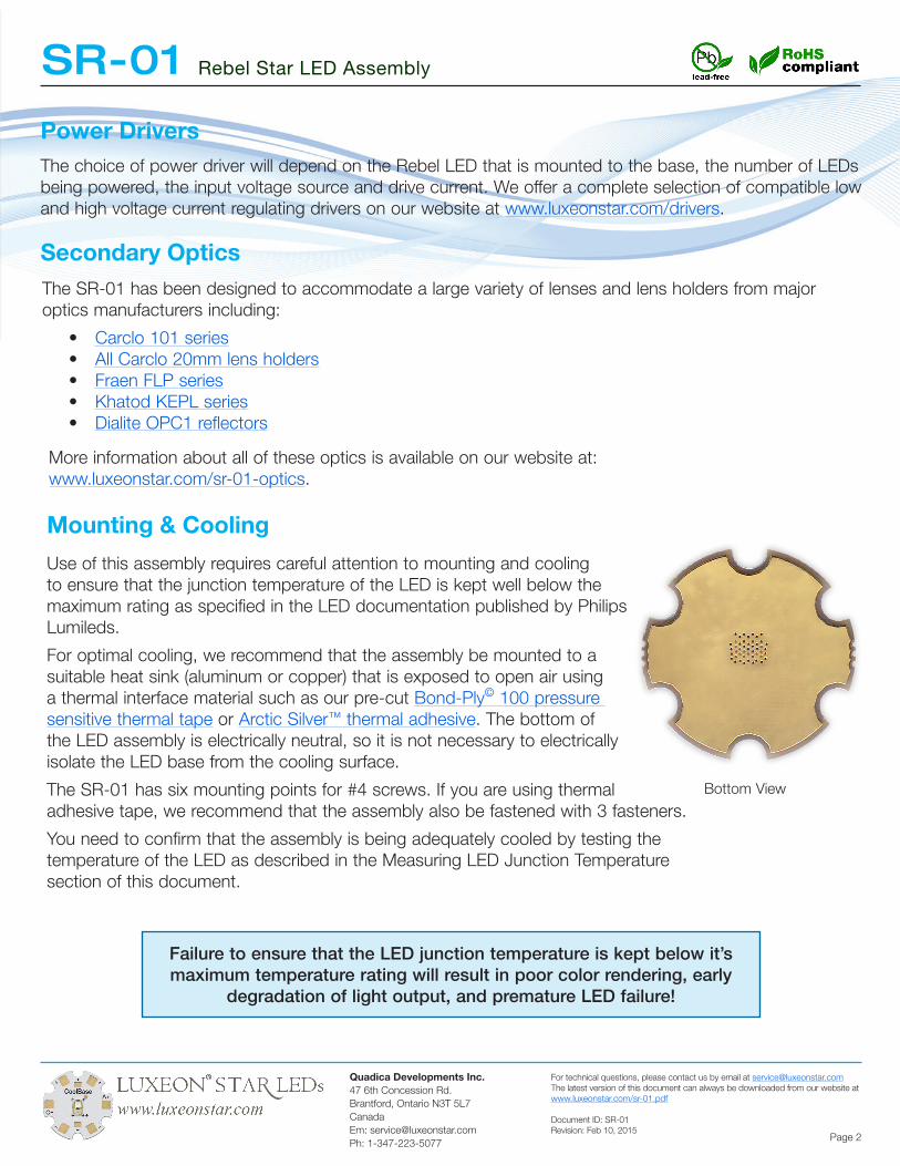
For optimal cooling, we recommend that the assembly be mounted to a suitable heat sink (aluminum or copper) that is exposed to open air using a thermal interface material such as our pre-cut Bond-Ply© 100 pressure sensitive thermal tape or Arctic Silver™ thermal adhesive. The bottom of the LED assembly is electrically neutral, so it is not necessary to electrically isolate the LED base from the cooling surface.
The SR-01 has six mounting points for #4 screws. If you are using thermal adhesive tape, we recommend that the assembly also be fastened with 3 fasteners.
You need to confirm that the assembly is being adequately cooled by testing the temperature of the LED as described in the Measuring LED Junction Temperature section of this document.
Failure to ensure that the LED junction temperature is kept below it’s maximum temperature rating will result in poor color rendering, early
degradation of light output, and premature LED failure!
Bottom View
SR-01 Rebel Star LED Assembly
Quadica Developments Inc.47 6th Concession Rd.Brantford, Ontario N3T 5L7Canada Em: [email protected]: 1-347-223-5077
For technical questions, please contact us by email at [email protected] latest version of this document can always be downloaded from our website at www.luxeonstar.com/sr-01.pdf
Document ID: SR-01Revision: Feb 10, 2015
Page 3
Measuring LED Junction Temperature
The junction temperature of the LED must be tested to be sure it is being adequately cooled.
To make testing easy, the SR-01 assembly includes a temperature test point that can be used to determine the LED junction temperature using the following procedure.
1. Enter the LED Typical Thermal Resistance Junction to Thermal Pad (°C/W) RθJ-C value from the Rebel LED datasheet into box B in the formula on page 5 of this document.
2. Ideally the temperature should be tested with the LED assembly mounted in the location where it will be operated.
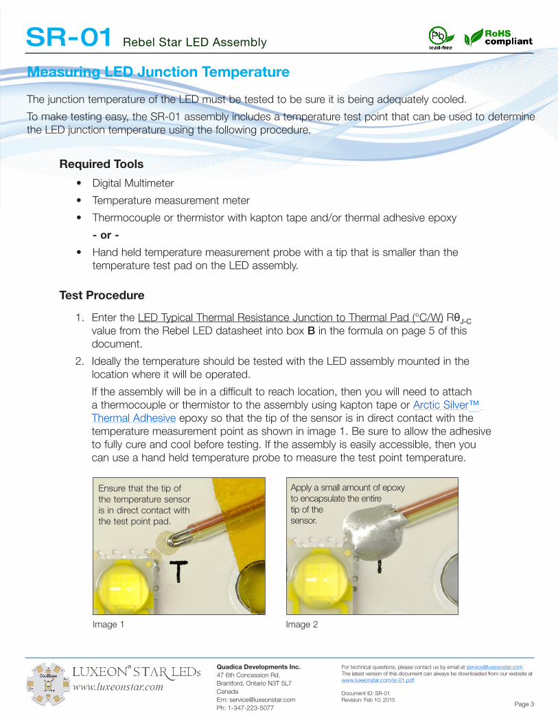
If the assembly will be in a difficult to reach location, then you will need to attach a thermocouple or thermistor to the assembly using kapton tape or Arctic Silver™ Thermal Adhesive epoxy so that the tip of the sensor is in direct contact with the temperature measurement point as shown in image 1. Be sure to allow the adhesive to fully cure and cool before testing. If the assembly is easily accessible, then you can use a hand held temperature probe to measure the test point temperature.
• Digital Multimeter
• Temperature measurement meter
• Thermocouple or thermistor with kapton tape and/or thermal adhesive epoxy
- or -
• Hand held temperature measurement probe with a tip that is smaller than the temperature test pad on the LED assembly.
Required Tools
Test Procedure
Image 1 Image 2
Ensure that the tip of the temperature sensor is in direct contact with the test point pad.
Apply a small amount of epoxy to encapsulate the entiretip of thesensor.
SR-01 Rebel Star LED Assembly
Quadica Developments Inc.47 6th Concession Rd.Brantford, Ontario N3T 5L7Canada Em: [email protected]: 1-347-223-5077
For technical questions, please contact us by email at [email protected] latest version of this document can always be downloaded from our website at www.luxeonstar.com/sr-01.pdf
Document ID: SR-01Revision: Feb 10, 2015
Page 4
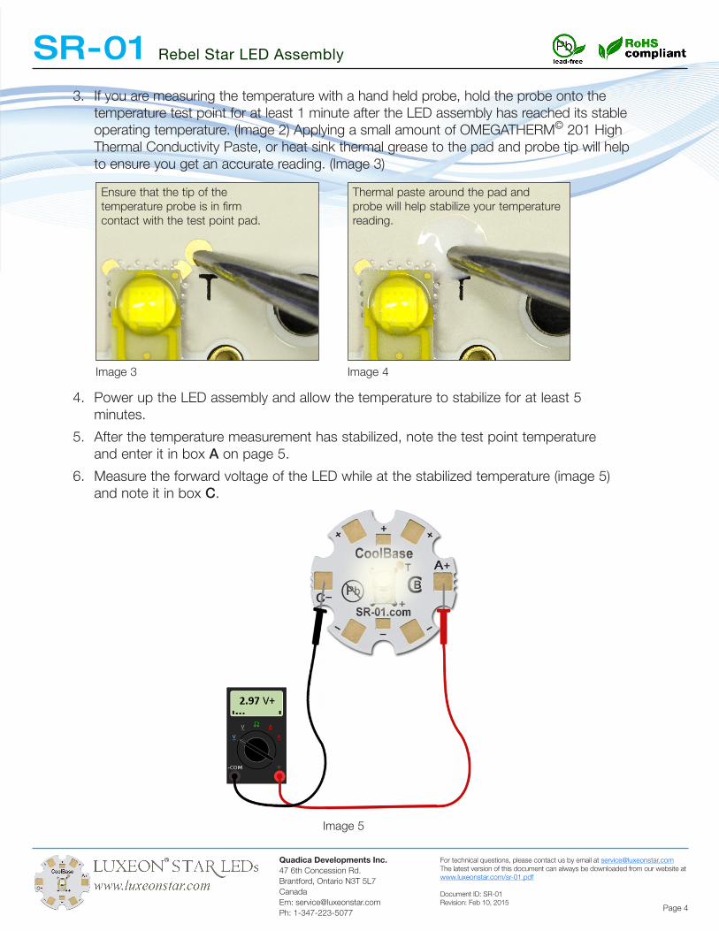
3. If you are measuring the temperature with a hand held probe, hold the probe onto the temperature test point for at least 1 minute after the LED assembly has reached its stable operating temperature. (Image 2) Applying a small amount of OMEGATHERM© 201 High Thermal Conductivity Paste, or heat sink thermal grease to the pad and probe tip will help to ensure you get an accurate reading. (Image 3)
4. Power up the LED assembly and allow the temperature to stabilize for at least 5 minutes.
5. After the temperature measurement has stabilized, note the test point temperature and enter it in box A on page 5.
6. Measure the forward voltage of the LED while at the stabilized temperature (image 5) and note it in box C.
Image 3 Image 4
Image 5
Ensure that the tip of the temperature probe is in firm contact with the test point pad.
Thermal paste around the pad and probe will help stabilize your temperature reading.
SR-01 Rebel Star LED Assembly
Quadica Developments Inc.47 6th Concession Rd.Brantford, Ontario N3T 5L7Canada Em: [email protected]: 1-347-223-5077
For technical questions, please contact us by email at [email protected] latest version of this document can always be downloaded from our website at www.luxeonstar.com/sr-01.pdf
Document ID: SR-01Revision: Feb 10, 2015
Page 5
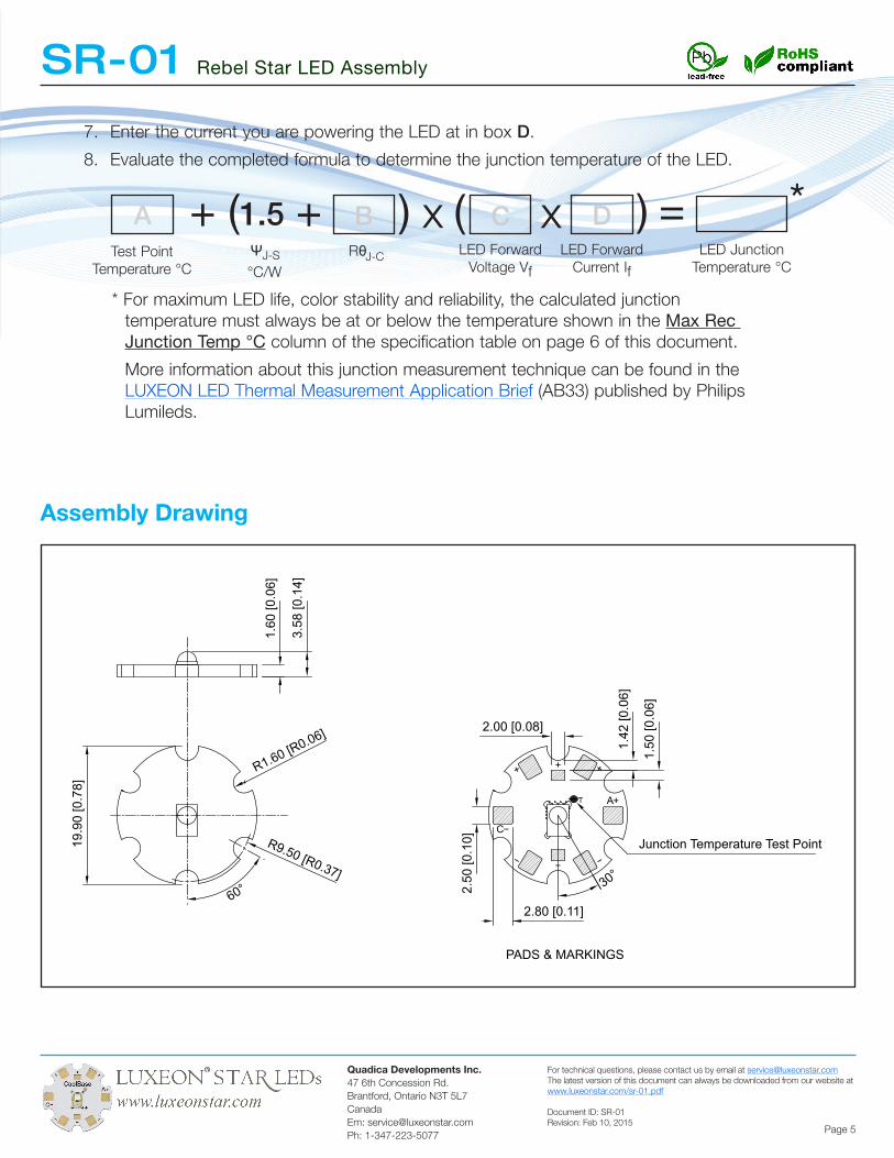
Assembly Drawing
+++
A
C
+
PADS & MARKINGS
T
19.9
0 [0
.78]
60°
R9.50 [R0.37]
R1.60 [R0.06]
1.60
[0.0
6]
3.58
[0.1
4]
2.50
[0.1
0]
1.42
[0.0
6]
1.50
[0.0
6]
2.00 [0.08]
30°
Junction Temperature Test Point
2.80 [0.11]
7. Enter the current you are powering the LED at in box D.
8. Evaluate the completed formula to determine the junction temperature of the LED.
* For maximum LED life, color stability and reliability, the calculated junction temperature must always be at or below the temperature shown in the Max Rec Junction Temp °C column of the specification table on page 6 of this document.
More information about this junction measurement technique can be found in the LUXEON LED Thermal Measurement Application Brief (AB33) published by Philips Lumileds.
A + 1.5 x ( =C Dx )Test Point
Temperature °CLED Forward
Voltage Vf
LED Forward Current If
LED Junction Temperature °C
ΨJ-S
°C/W
B( )+J-CRθ
*
SR-01 Rebel Star LED Assembly
Quadica Developments Inc.47 6th Concession Rd.Brantford, Ontario N3T 5L7Canada Em: [email protected]: 1-347-223-5077
For technical questions, please contact us by email at [email protected] latest version of this document can always be downloaded from our website at www.luxeonstar.com/sr-01.pdf
Document ID: SR-01Revision: Feb 10, 2015
Page 6
Although QUADICA DEVELOPMENTS INC. has attempted to provide the most accurate information and services data (hereinafter “Data”), the Data is provided “as is” and may contain errors. The entire risk of use of the data shall be with the user. QUADICA DEVELOPMENTS INC. makes no warranty, express or implied, including, but not limited to, the implied warranties of merchantability and fitness for a particular purpose, regarding the contents or correctness of the Data provided or the ability of the Data to meet the user’s needs or expectations. QUADICA DEVELOPMENTS INC. reserves the right to make changes and corrections without notice.
You as the user agree to this disclaimer and the user agreement with the download or use of the provided Data. In no event shall QUADICA DEVELOPMENTS INC. be liable for any direct, indirect, special, incidental, exemplary, or consequential damages arising out of or related to the use of the Data, however caused, regardless of theory of liability, and whether or not QUADICA DEVELOPMENTS INC. has been advised of the possibility of such damage. This limitation shall apply notwithstanding any failure of essential purpose or any exclusive remedy.
Disclaimer:
Restricted Use:
Products produced or sold by Quadica Developments Inc. are not certified for use as critical components in life support devices, systems, nor in medical operating room or life rescue equipment. A critical component is any component of a life support device, system or medical/rescue equipment whose failure to perform can be reasonably expected to cause failure or malfunction of the life support device, system or medical operating room/life rescue equipment.
Safety:The LED mounted onto this assembly will produce a highly intense point of light. Do not stare directly at the LED for any length of time.


![Rebel. Catalogo Rebel Lures 2011 [USA]](https://img.dokumen.tips/doc/110x75/568bd9431a28ab2034a6655b/rebel-catalogo-rebel-lures-2011-usa.jpg)