Embed Size (px)
Citation preview
Sputtering (cont.) and Other Plasma Processes
Sputtering Summary
•
Create an ionic plasma by applying a high voltage to a glow tube.
•
Ions bombard the target material at the cathode.
•
Target atoms are ejected (sputtered) from the cathode by energy and momentum transfer.
•
Sputtered atoms from the target are deposited on to the substrate (anode).
Keys to Proper Sputtering•
The right choice of ions –
The atomic weights of the ions and the target atoms should be close.
•
The right pressure for a sustainable plasma –
10-1000 mTorr•
The right cathode voltage so that the ions have the right energy for sputtering–
Eion
> 100 eV and Vcath
~ 2-5 kV•
The right angle for high sputter yield –
60°
-
70°
from normal•
The right substrate voltage and temperature for a clean film
Glow Discharge Sputtering
•
As the gas molecules are ionized and energized by collisions, eventually they will have enough energy to cause ejection of atoms from the cathode surface.
•
This is not a very efficient system (ionic MFPs are very low due to their high mass).
•
The film quality is not very good due to the high pressures required to maintain the glow.
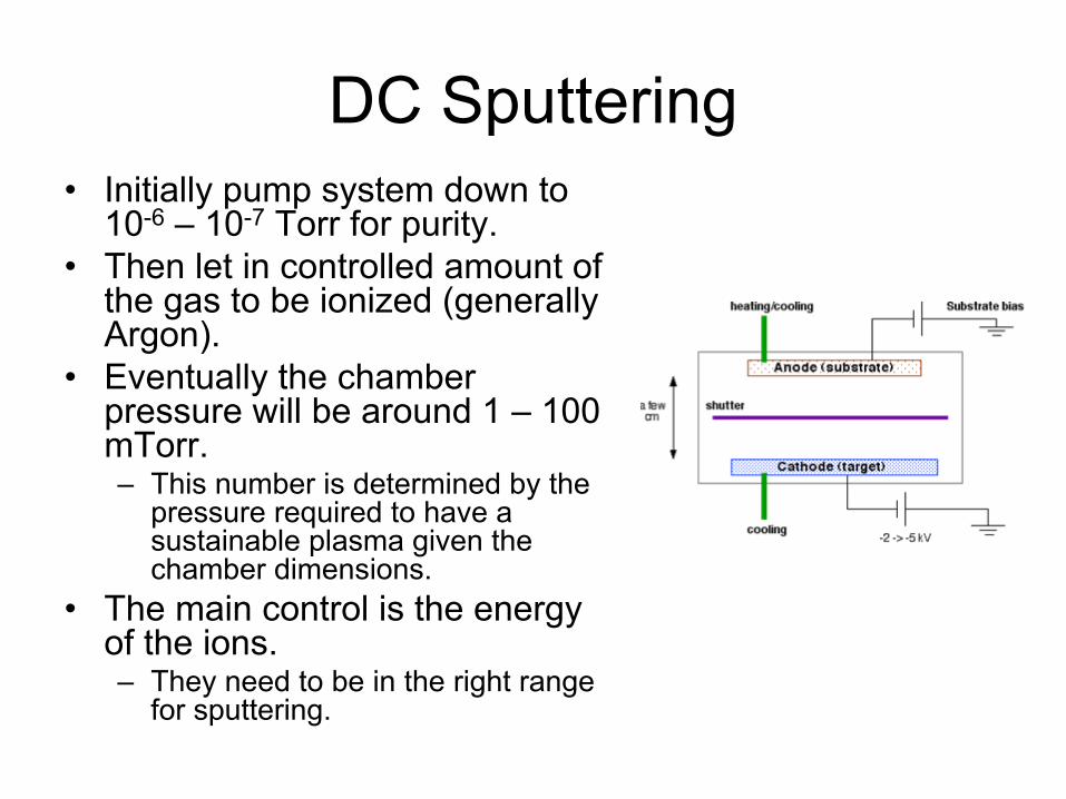
DC Sputtering•
Initially pump system down to 10-6
– 10-7
Torr for purity.•
Then let in controlled amount of the gas to be ionized (generally Argon).
•
Eventually the chamber pressure will be around 1 –
100
mTorr.–
This number is determined by the pressure required to have a sustainable plasma given the chamber dimensions.
•
The main control is the energy of the ions.–
They need to be in the right range for sputtering.

Some Limitations of DC Sputtering
•
The high pressures required to achieve a plasma can degrade film quality.
•
Only a small fraction of the gas is converted to ions.
•
All of this results in deposition rates that are low (~ 100 Ǻ
/ min).
Substrate Biasing•
Applying a small negative voltage to the substrate (50 –
300 V)
•
Removes physisorbed (adsorbed) contaminants such as Oxygen
•
Also, by increasing the energy of the surface atoms enhances diffusion–
This improves adhesion, nucleation and crystal structure.
•
Other modifications to DC sputtering (hollow cathode, triode) enhance ionization and enable lower gas pressures.
The Major Limitation of DC Sputtering
•
Suppose instead of a metal, we want to sputter an insulator like quartz.
•
Due to the high resistivity of the target running an appreciable current through would require an impossibly large voltage (~1012
V).
•
The lack of a current will extinguish the plasma and stop the process.
•
Practically this limits DC sputtering to materials of a resistivity less than 106
Ω.cm
(no insulators).
AC Plasmas•
Now recall that the effective resistance of dielectrics can vary with the frequency of the applied current (impedance).
•
A capacitevly
coupled AC plasma (like a sputteirng system) would see a lower impedance and therefore
reasonable voltages can still sustain current through the target.
•
At low frequencies both the ions and electrons can react to the change in voltage polarity and essentially a DC plasma that changes sides prevails.
•
Above ~ 1MHz, the heavier ions can not react to the voltage changes while the lighter electrons can follow them without problems.
•
The higher mobility of the electrons enables them to be more energetic and increases the plasma density.
Target Self-Bias•
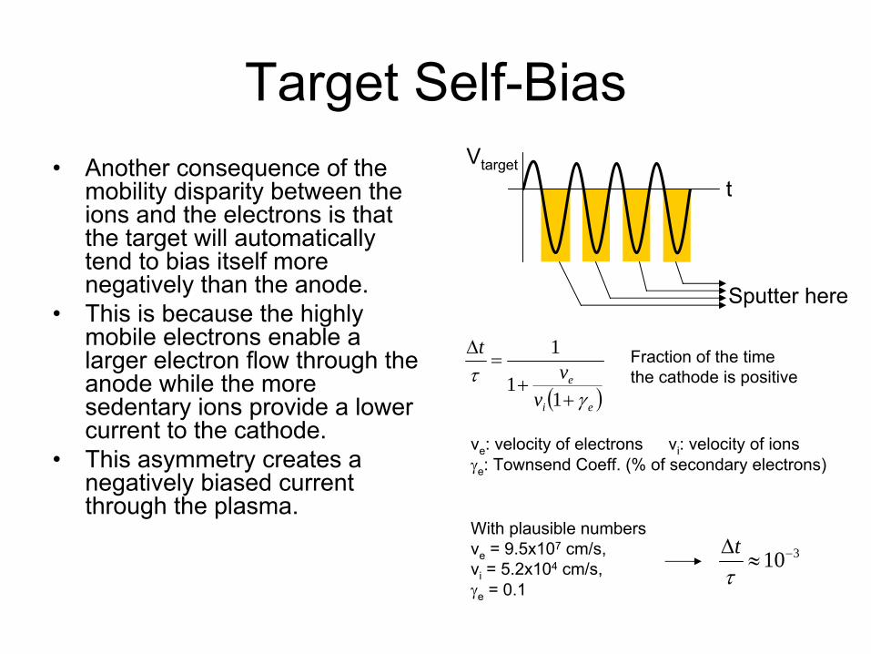
Another consequence of the mobility disparity between the ions and the electrons is that the target will automatically tend to bias itself more negatively than the anode.
•
This is because the highly mobile electrons enable a larger electron flow through the anode while the more sedentary ions provide a lower current to the cathode.
•
This asymmetry creates a negatively biased current through the plasma.
( )ei
e
vv
t
γτ
++
=Δ
11
1 Fraction of the time the cathode is positive
With plausible numbersve
= 9.5x10⁷
cm/s, vi
= 5.2x10⁴
cm/s, γe
= 0.1
310−≈Δτt
Vtarget
t
Sputter here
ve
: velocity of electrons
vi
: velocity of ionsγe
: Townsend Coeff. (% of secondary electrons)
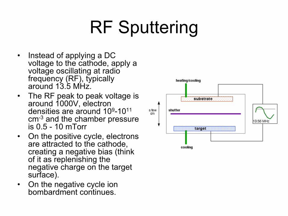
RF Sputtering•
Instead of applying a DC voltage to the cathode, apply a voltage oscillating at radio frequency (RF), typically around 13.5 MHz.
•
The RF peak to peak voltage is around 1000V, electron densities are around 109-1011
cm-3
and the chamber pressure is 0.5 -
10 mTorr•
On the positive cycle, electrons are attracted to the cathode, creating a negative bias (think of it as replenishing the negative charge on the target surface).
•
On the negative cycle ion bombardment continues.
RF Sputtering Details•
By avoiding a constant negative voltage on the cathode, ion buildup is prevented for insulating targets.
•
Can operate at lower pressures while still sustaining a plasma.
•
RF plasmas tend to fill the chamber as opposed to DC plasmas which are confined to the cathode.
•
Normally both the target and substrate should sputter. This can be overcome by making the target area small compared to the substrate.
•
While any type of film can be RF sputtered, deposition rates are still low.
•
Applying RF power is not so simple, power supplies are expensive and additional circuitry is needed.
Magnetron Sputtering
•
Plasma generation is an inefficient process. –
Less than 0.1% ionization rate
•
Can increase chamber pressure–
Degrade film quality, lose plasma
•
Solution: Use secondary electrons more efficiently to generate plasma.

Magnetron Sputtering
•
Normally once an electron is kicked out of the surface it travels more or less in a straight line between collisions.
•
Under the influence of the cathode-anode voltage, it will drift towards the anode.
•
If we can confine the electrons near the cathode, their high density will increase the plasma density and make for more efficient sputtering.
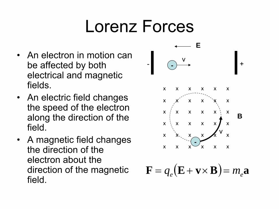
Lorenz Forces•
An electron in motion can be affected by both electrical and magnetic fields.
•
An electric field changes the speed of the electron along the direction of the field.
•
A magnetic field changes the direction of the electron about the direction of the magnetic field.
-- +v
x x x x x x
x x x x x x
x x x x x x
x x x x x x
x x x x x x
E
B
v-
x x x x x x
( ) aBvEF ee mq =×+=
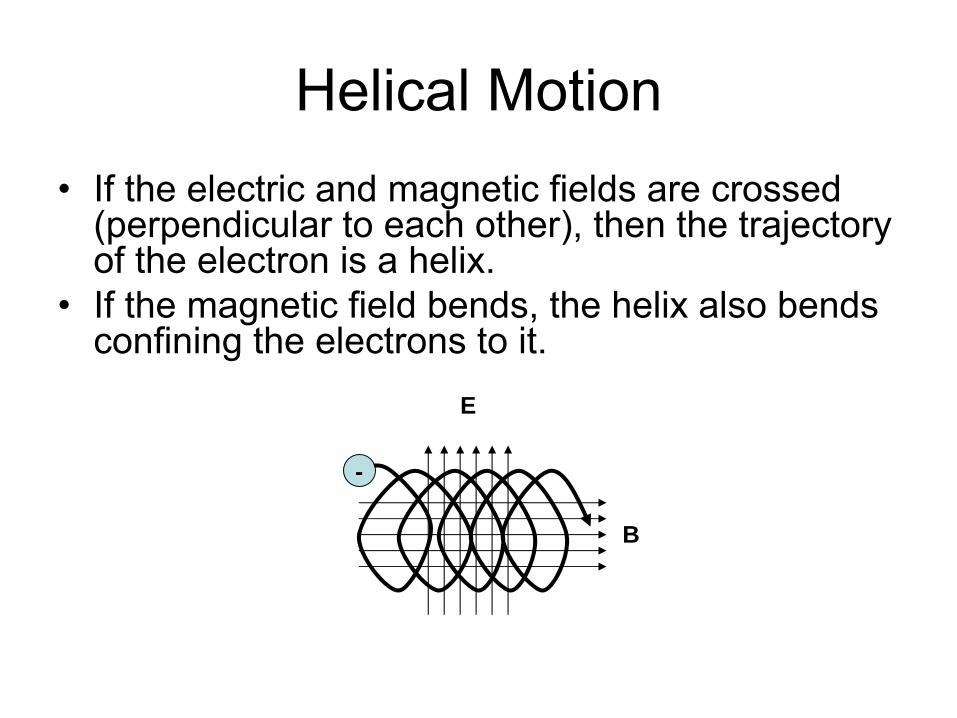
Helical Motion•
If the electric and magnetic fields are crossed (perpendicular to each other), then the trajectory of the electron is a helix.
•
If the magnetic field bends, the helix also bends confining the electrons to it.
-
B
E
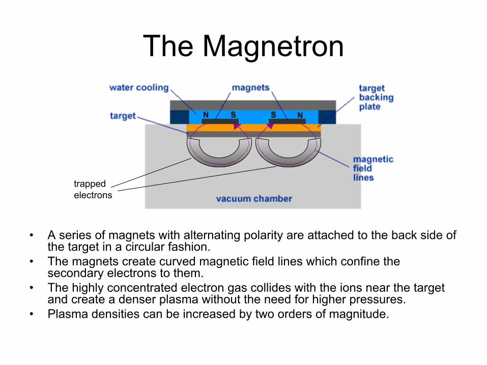
The Magnetron
•
A series of magnets with alternating polarity are attached to the back side of the target in a circular fashion.
•
The magnets create curved magnetic field lines which confine the
secondary electrons to them.
•
The highly concentrated electron gas collides with the ions near
the target and create a denser plasma without the need for higher pressures.
•
Plasma densities can be increased by two orders of magnitude.
trapped electrons
Practical Considerations
•
A stationary magnetic field will produce permanent regions where the plasma is strong
•
This will create erosion rings on the target.•
This affects film uniformity and requires frequent replacement of the target.
•
To avoid this oddly shaped and rotating magnetron rings are used.

Reactive Sputtering•
A combination of physical and chemical deposition.
•
Used to deposit compounds (oxides, nitrides).•
Add a reactive gas (oxygen, nitrogen) to the inert gas flow.
•
The reactive gas goes in to a chemical reaction with the sputtered atoms.
•
If the sputtering rate is faster than the chemical reaction rate, then the reaction will take place on the substrate.
•
Adjust gas flow to get good stochiometry (chemical composition).
•
Examples: Al2
O3
, AlN, TiO, TiN, SiO2
Issues with Reactive Sputtering•
As more and more reactive gas is introduced into the system, target oxidation or nitridation can occur.
•
This leads to drastically reduced sputter yields and deposition rates.
•
The oxidation/nitridation is a runaway process. Beyond a critical gas pressure, it progresses rapidly.
•
Best oxide films are obtained just below this critical point.•
One solution is to oscillate the cathode voltage like RF sputtering but at a lower frequency (~100 KHz).
Sputtering of Alloys
•
Alloy sputtering is a self-regulating process.
•
If the sputter yield of one species (A) is larger than the other (B), then the surface will initially be depleted of A.
•
Now, since the surface has more of B, more of it will sputter off.
•
An equilibrium will be reached around the stochiometric
ratio.
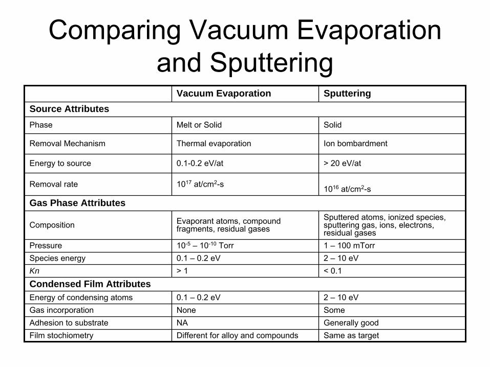
Comparing Vacuum Evaporation and Sputtering
Vacuum Evaporation SputteringSource AttributesPhase Melt or Solid Solid
Removal Mechanism Thermal evaporation Ion bombardment
Energy to source 0.1-0.2 eV/at > 20 eV/at
Removal rate 1017
at/cm2-s 1016
at/cm2-s
Gas Phase Attributes
Composition Evaporant atoms, compound fragments, residual gases
Sputtered atoms, ionized species, sputtering gas, ions, electrons, residual gases
Pressure 10-5
– 10-10
Torr 1 –
100 mTorrSpecies energy 0.1 –
0.2 eV 2 –
10 eVKn > 1 < 0.1Condensed Film AttributesEnergy of condensing atoms 0.1 –
0.2 eV 2 –
10 eVGas incorporation None SomeAdhesion to substrate NA Generally goodFilm stochiometry Different for alloy and compounds Same as target
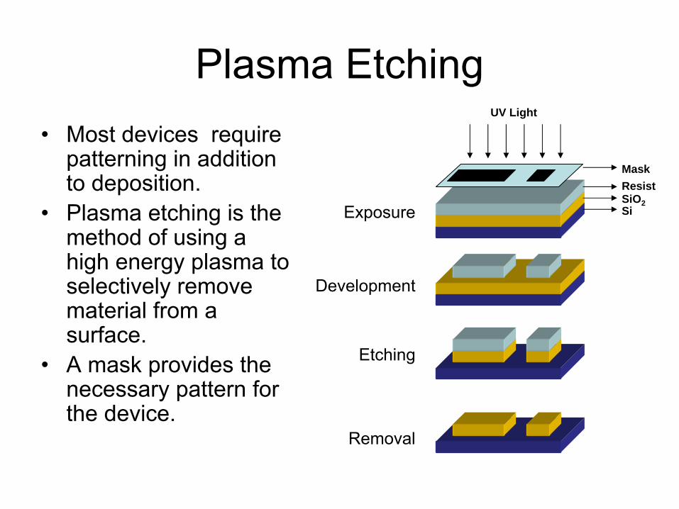
Plasma Etching•
Most devices require patterning in addition to deposition.
•
Plasma etching is the method of using a high energy plasma to selectively remove material from a surface.
•
A mask provides the necessary pattern for the device.
SiSiO2
ResistMask
UV Light
Exposure
Development
Etching
Removal
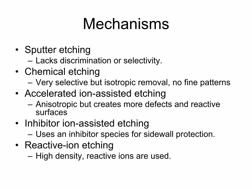
Mechanisms•
Sputter etching–
Lacks discrimination or selectivity.
•
Chemical etching–
Very selective but isotropic removal, no fine patterns
•
Accelerated ion-assisted etching–
Anisotropic but creates more defects and reactive surfaces
•
Inhibitor ion-assisted etching–
Uses an inhibitor species for sidewall protection.
•
Reactive-ion etching–
High density, reactive ions are used.
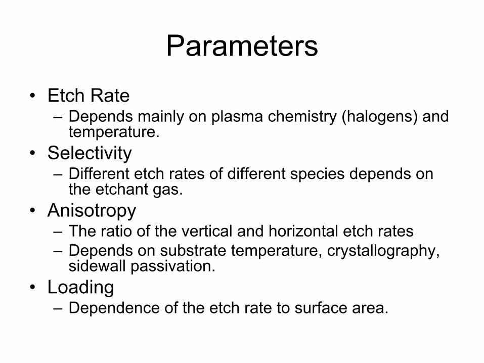
Parameters•
Etch Rate–
Depends mainly on plasma chemistry (halogens) and temperature.
•
Selectivity–
Different etch rates of different species depends on the etchant gas.
•
Anisotropy–
The ratio of the vertical and horizontal etch rates
–
Depends on substrate temperature, crystallography, sidewall passivation.
•
Loading–
Dependence of the etch rate to surface area.
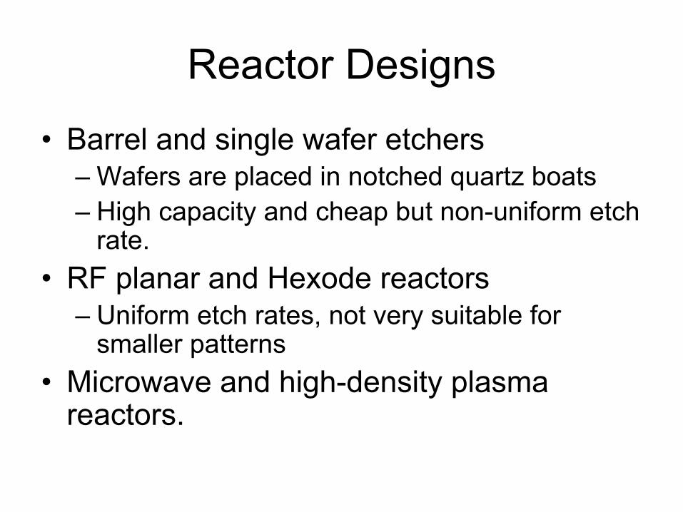
Reactor Designs
•
Barrel and single wafer etchers–
Wafers are placed in notched quartz boats
–
High capacity and cheap but non-uniform etch rate.
•
RF planar and Hexode reactors–
Uniform etch rates, not very suitable for smaller patterns
•
Microwave and high-density plasma reactors.