Embed Size (px)
Citation preview
Research Journal of Nanoscience and Engineering
Volume 2, Issue 1, 2018, PP 1-8
Research Journal of Nanoscience and Engineering V2 ● I1 ● 2018 1
Effect of Gas Pressure and Flow Rate on the Plasma Power and
Deposition Rate in Magnetron Sputtering System
Musaab Salman Sultan
Information Security Department, Technical College of Informatics-Akre, Dohuk Polytechnic
University, 42004, Kurdistan Region, Iraq.
*Corresponding Author: Musaab Salman Sultan, Information Security Department, Technical College of Informatics-Akre, Dohuk Polytechnic University, 42004, Kurdistan Region, Iraq.
INTRODUCTION
A range of fabrication techniques have been
widely used to deposit ferromagnetic thin films
and nanostructures. Each technique has its own
compensations and drawbacks. Among these
techniques, sputtering has been proved to be
simple, fast and low cost technique. Sputtering,
however, can be defined as the removal of the
surface material when it is bombarded with
highly energetic ions. It was first discovered in
1852 by W. R. Grove when he was working on
the electrical conductivity of gases [1].
In a sputtering system, an electric field is
applied between two metallic electrodes known
as the cathode and the anode that are sited in an
evacuated chamber. The electrodes can be
connected to a D.C. or R.F. electrical power
supply [1]. A schematic description of a
conventional sputtering system is shown in
Figure 1(a). The target material is usually placed
on the surface of the cathode. The chamber is
filled with a low pressure inert gas, such as;
argon, xenon and krypton. The gas becomes
positively ionised when a sufficient electric field
is applied to strike the glow discharge (plasma)
between the two electrodes [1-3].
Due to the negative voltage of the target, the
positive ions are accelerated towards the target.
As a result different phenomena can occur
depending on the type of the material making up
the target, the ion type, the ion energy, and other
factors, including gas flow rate, gas pressure,
plasma power, electrode dimensions, electrode
spacing, the ratio of the electrode dimensions to
the electrode spacing as well as the target
history and deposition geometry[1-8]. These
phenomena are: the ejection of atoms from the
target, scattering and neutralisation of ions, the
production of secondary electrons and ions, and
ion implantation in the target with or without
simultaneous target atom ejection [1,4].
ABSTRACT
In this contribution, the effect of gas pressure and gas flow rate on the voltage (power) required to strike &
maintain an argon plasma and the current – voltage characteristics as well as the deposition rates were investigated in detail using both ferromagnetic Ni as well as Ni81Fe19 targets. A reduction in the voltage
required to strike the plasma as the gas pressure and gas flow rate increased in the sputtering chamber and
was attributed to the high probability of the ionisation process with increased gas pressure and gas flow
rates. The relation between the voltage required to strike the glow discharge and the plasma current, showed
a strong linear dependence under all gas pressures and gas flow rates investigated here. The current -
voltage relations showed a transition regions which were more clearly noticeable at low gas pressures and
gas flow rates. They were attributed to the small amount of gas that existed in the chamber which in turn
reduced the ionisation process. For constant gas pressure, lower voltage is required to strike the plasma
when the gas flow rate is high and vice versa. The effect of the plasma power on the deposition rate under
different gas pressure and flow rate was also considered here. The deposition rate was directly proportional
to the plasma power where it increased linearly with increased plasma power. This means that the number of ejected atoms from the target increased linearly by increasing the target power. However, there was a slight
reduction in the deposition rate by increasing the gas pressure and flow rates especially at high plasma
power. This was attributed to the collisions enhancement among the ejected particlesor/and the gas atoms
or due to the reduction in the thermal energy of the sputtered atoms and changing their direction far from
the substrate.
Keywords: Current-Voltage characteristics, Glow discharge, Gas flow rate, Gas pressure, Plasma power.
Effect of Gas Pressure and Flow Rate on the Plasma Power and Deposition Rate in Magnetron Sputtering
System
2 Research Journal of Nanoscience and Engineering V2 ● I1 ● 2018
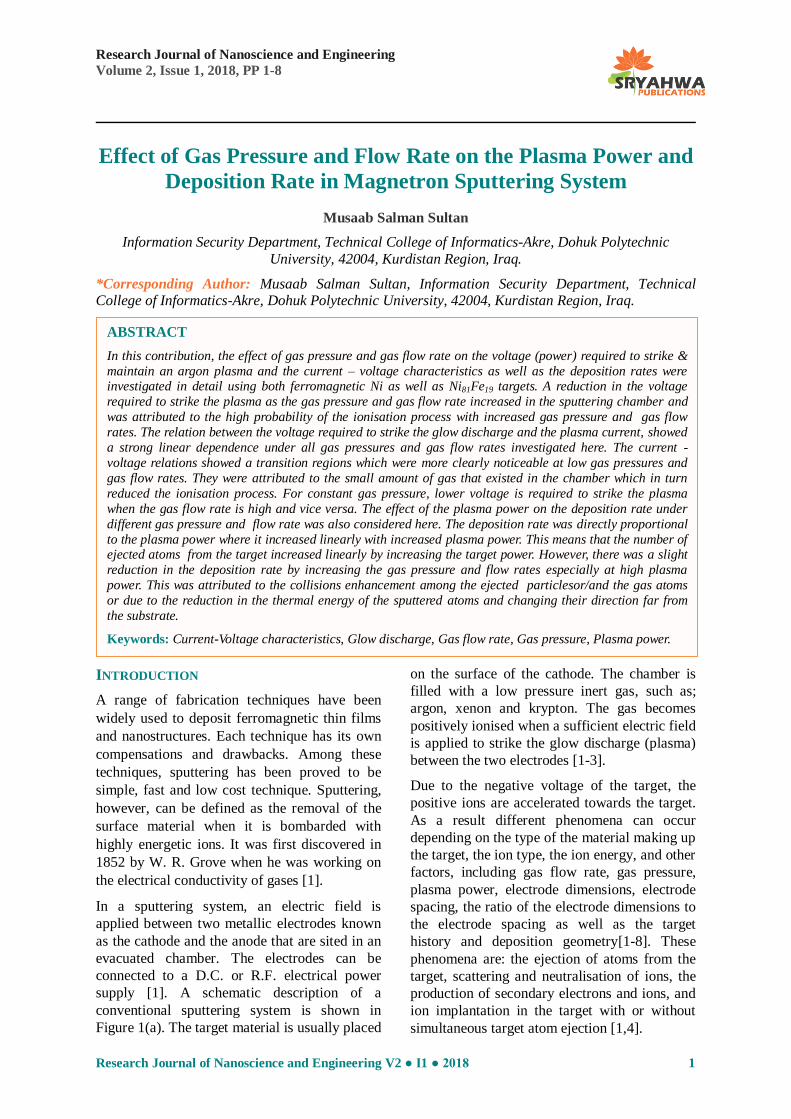
Figure1. Schematic diagram of (a) conventional, and (b) magnetron sputtering systems. Atoms are ejected from
the target surface as a result of bombardment by ions such as argon or krypton ions. A series of permanent
magnets is placed behind the target to capture the escaping electrons and increase the sputtered atoms.
The most important phenomenon in sputtering system is the ejection of atoms from the target.
There are two different theories explaining this
ejection [1,4]. The first theory is thermal vaporisation in which the ejection of atoms is
due to the local vaporisation of the target
surface as a result of heating due to the bombardment of high energy ions [1,4]. The
second concept is the direct momentum transfer
in which the sputtering occurs as a result of the
transfer of kinetic energy from the incident ions to the target surface atoms and sputtering occurs
as a result of the collision cascade in the surface
of the target [1,4].
In the conventional sputtering system, however,
high gas pressure is required to create the
plasma between the two electrodes because
there is a problem that not all the free electrons contribute to produce the plasma, thus reduces
the rate of material deposited on to the substrate
and increases the contamination [1,4]. Placing permanent magnets behind the target as
schematically shown in Figure 1(b), to form a magnetron source was found to be effective in
reducing the gas pressure needed for producing
the plasma, increasing the rate of material deposited on to the substrate up to one order of
magnitude with a very low contamination in the
deposited films [1,9]. This is because the permanent magnet produces a magnetic field
that extends parallel to the target surface and
perpendicular to the plasma, thus captures the
escaping electrons and densifying them in the immediate area of the target where they move in
a spiral motion and as a result increase the ion
bombardment and hence the number of sputtered atoms [9].
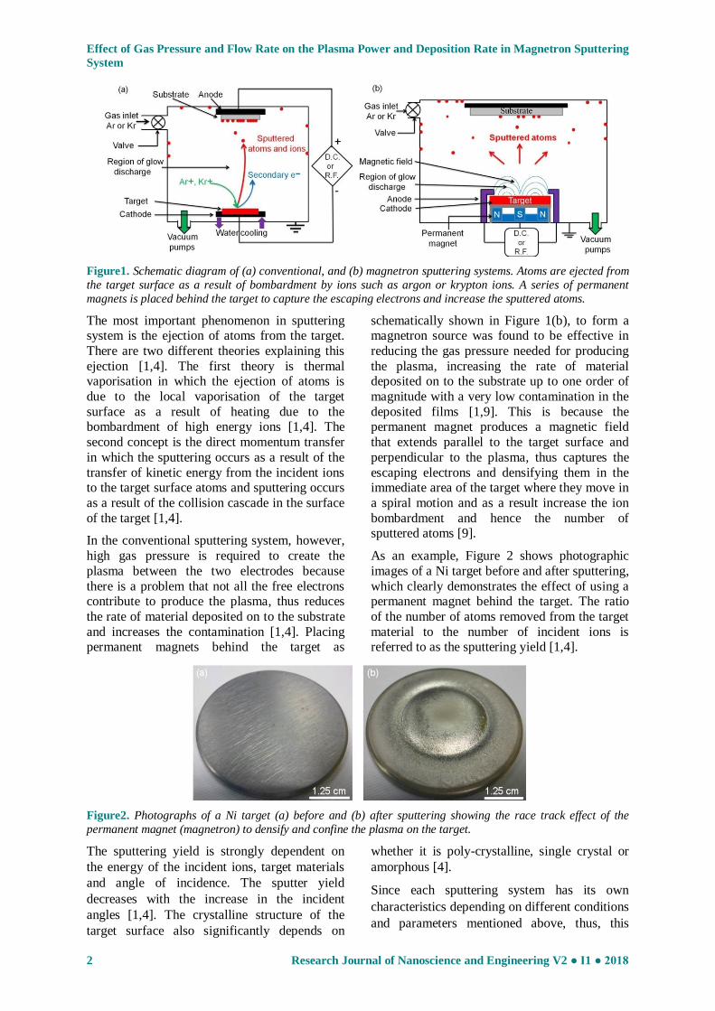
As an example, Figure 2 shows photographic
images of a Ni target before and after sputtering,
which clearly demonstrates the effect of using a permanent magnet behind the target. The ratio
of the number of atoms removed from the target
material to the number of incident ions is referred to as the sputtering yield [1,4].
Figure2. Photographs of a Ni target (a) before and (b) after sputtering showing the race track effect of the
permanent magnet (magnetron) to densify and confine the plasma on the target.
The sputtering yield is strongly dependent on
the energy of the incident ions, target materials
and angle of incidence. The sputter yield
decreases with the increase in the incident
angles [1,4]. The crystalline structure of the
target surface also significantly depends on
whether it is poly-crystalline, single crystal or
amorphous [4].
Since each sputtering system has its own
characteristics depending on different conditions
and parameters mentioned above, thus, this

Effect of Gas Pressure and Flow Rate on the Plasma Power and Deposition Rate in Magnetron Sputtering
System
Research Journal of Nanoscience and Engineering V2 ● I1 ● 2018 3
article critically discusses the effect of gas
pressure and gas flow rate on the voltage needed
to strike the glow discharge and maintain it. The
current - voltage characteristics of the plasma
and the effect of the plasma power on the
deposition rate under these conditions is also
analyzed. All these measurements were
performed using two different compositions of
ferromagnetic Ni and NiFe targets.
EXPERIMENTAL PROCEDURE
The magnetron sputtering system used here to
investigate the most significant characteristics is
shown in Figure 3(a). The lowest base pressure achieved within this system was around 2×10
-6T
using a combination of rotary and turbo
molecular pumps. This pressure may have been limited by the very large O-ring seal on the top
flange. The sputtering gas used here was argon
gas with a purity of 99.9 %, which entered the vacuum chamber through a variable leak gate
valve. The gas flow rate in the chamber was
controlled via this gate valve. When this valve
was closed, a low flow rate was achieved and when it was half opened, medium flow rate was
defined, and a high flow rate was obtained with
a fully open gate valve.
Different targets of ferromagnetic materials can
be used with this system, but in this
investigation, ferromagnetic Ni and Ni81Fe19
were used. They were discs with a 50 mm
diameter and 99.99 % purity. The target was
mounted by mechanical supports on a water
cooled backing plate and surrounded by a
metallic shield, which acts as the anode. The
construction of the magnetron and the target is
shown in Figure 3(b). Throughout the work
presented here, the distance between the anode
and the target surface (cathode) was kept
constant at ~3 mm. The distance between the
target surface and the substrate holder was also
kept constant at ~90 mm.
To provide the power needed to strike and
maintain an argon plasma, the anode and the
cathode were connected to a DC power supply
with a maximum voltage of ~600 volts and a
power ~3.6 kW. The target voltage and plasma
current were measured with digital multi-
meters.
Figure3. Photographs of (a) DC magnetron sputtering system used in this article to investigate the most
significant characteristics of it, and (b) the target set of this system in which the cathode is a planar disc of the material to be deposited surrounded by a metallic anode shield.
The deposition rate and film thickness were
monitored during the film growth using a quartz
crystal oscillator. This oscillator was calibrated
using X–ray reflectivity scan [10].
Before starting the work presented here, the
chamber was flushed with argon gas for
approximately 5 minutes, in order to remove the
residual air molecules or water vapour inside the
chamber if any were left after evacuation. To
clean the target surface from oxides or any other
contaminates, a pre-sputtering process was
performed for a time of ~5 minutes.
RESULTS AND DISCUSSION
The following subsections thoroughly discuss
the most important results obtained from the characterisation of the magnetron sputtering
system which is shown in Figure 3. A detailed
analysis was performed to study the effect of gas pressure (3 mT - 8 mT ) and gas flow rates
(low, medium and high) in the sputtering
Effect of Gas Pressure and Flow Rate on the Plasma Power and Deposition Rate in Magnetron Sputtering
System
4 Research Journal of Nanoscience and Engineering V2 ● I1 ● 2018
chamber on the voltage (power) required to
strike the glow discharge & maintain it. The relation between the plasma power and the
deposition rate under these conditions was also
investigated here. The gas flow rates were controlled via the gate valve available in the
way of the gas outlet passage, as discussed in the
experimental section. All these measurements were performed using two ferromagnetic
compositions of Ni and Ni81Fe19 targets.
Effect of Gas Pressure and Gas Flow Rates
on the Plasma Voltage
The effect of gas pressure on the voltage which
was needed to strike the glow discharge &
maintain it under three different gas flow rates
was investigated. Examples of the results
obtained from this work are shown in Figure 4
using (a) Ni target and (b) Ni81Fe19 target and (c)
both results of Ni and Ni81Fe19 targets.
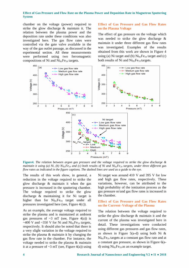
Figure4. The relation between argon gas pressure and the voltage required to strike the glow discharge &
maintain it using (a) Ni, (b) Ni81Fe19 and (c) both results of Ni and Ni81Fe19 targets, under three different gas
flow rates as indicated in the figure captions. The dashed lines are used as a guide to the eye.
The results of this work show, in general, a
reduction in the voltage required to strike the
glow discharge & maintain it when the gas
pressure is increased in the sputtering chamber.
The voltage required to strike the glow
discharge & maintaining it for Ni target is
higher than for Ni81Fe19 target under all
pressures investigated here (see, Figure 4(c)).
As an example, the average voltage required to
strike the plasma and is maintained at ambient
gas pressures of ~3 mT (see, Figure 4(a)) is
~400 V and ~350 V for Ni and Ni81Fe19 targets, respectively. It should also be noted that there is
a very slight variation in the voltage required to
strike the plasma & maintain it by changing the gas flow rate in the chamber. For instance, the
voltage needed to strike the plasma & maintain
it at a pressure of ~3 mT (see, Figure 4(a)) using
Ni target was around 410 V and 395 V for low
and high gas flow rates, respectively. These
variations, however, can be attributed to the
high probability of the ionization process as the gas pressure or/and gas flow rates is increased in
the chamber.
Effect of Gas Pressure and Gas Flow Rates
on the Current–Voltage of the Plasma
The relation between the voltage required to
strike the glow discharge & maintain it and the
current of the plasma was investigated here in
detail. These investigations were conducted
using different gas pressures and gas flow rates,
as shown in Figure 5(a-d) using both Ni &
Ni81Fe19 targets at a constant gas flow rate and at
a constant gas pressure, as shown in Figure 6(a-
d) using Ni81Fe19 as an example target.
Effect of Gas Pressure and Flow Rate on the Plasma Power and Deposition Rate in Magnetron Sputtering
System
Research Journal of Nanoscience and Engineering V2 ● I1 ● 2018 5
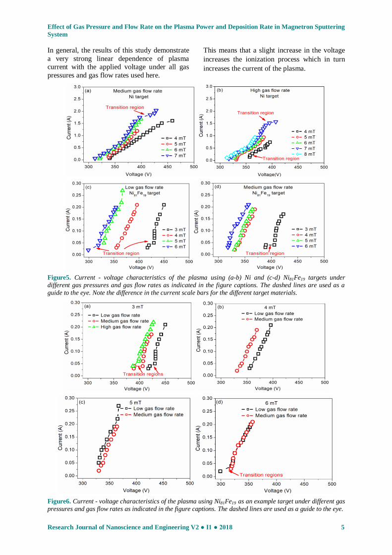
In general, the results of this study demonstrate
a very strong linear dependence of plasma current with the applied voltage under all gas
pressures and gas flow rates used here.
This means that a slight increase in the voltage
increases the ionization process which in turn
increases the current of the plasma.
Figure5. Current - voltage characteristics of the plasma using (a-b) Ni and (c-d) Ni81Fe19 targets under
different gas pressures and gas flow rates as indicated in the figure captions. The dashed lines are used as a
guide to the eye. Note the difference in the current scale bars for the different target materials.
Figure6. Current - voltage characteristics of the plasma using Ni81Fe19 as an example target under different gas
pressures and gas flow rates as indicated in the figure captions. The dashed lines are used as a guide to the eye.
Effect of Gas Pressure and Flow Rate on the Plasma Power and Deposition Rate in Magnetron Sputtering
System
6 Research Journal of Nanoscience and Engineering V2 ● I1 ● 2018
This relation also demonstrated a transition
regions which were more clearly noticeable at
low gas pressures and gas flow rates (see, for
example, Figure 6(a)). These transition regions
might appear as a result of the small amount of
gas which exist at low pressures and flow
rates,which in turn reduces the ionization
process and hence the plasma current.
Again from Figures 5 & 6, there is a remarkable
effect of the gas flow rate and gas pressure on
the voltage required to strike the plasma &
maintain it. For constant gas pressure (Figure
6(a-d)), lower voltage is required to strike the
plasma when the gas flow rate is high, whilst
higher voltage is required to strike the plasma
when the low gas flow rate is used. There is
clearly no effect of gas flow rate on this
behaviour, as the gas pressure increased in the
sputtering chamber to more than 6 mT (see,
Figure 6(a-d)). The discrepancy in the voltage
needed to strike the plasma & maintain it can be
attributed to the differences in the gas ionisation
with the change in the gas pressure and gas flow
rates.
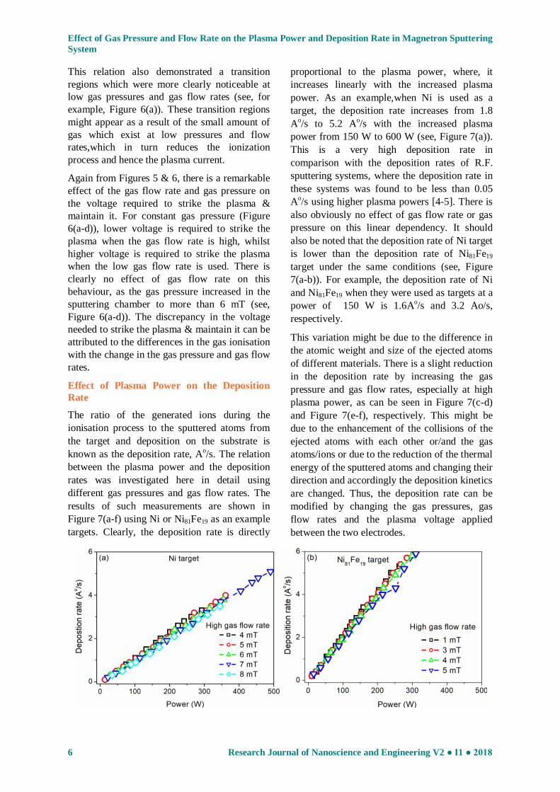
Effect of Plasma Power on the Deposition
Rate
The ratio of the generated ions during the
ionisation process to the sputtered atoms from
the target and deposition on the substrate is
known as the deposition rate, Ao/s. The relation
between the plasma power and the deposition
rates was investigated here in detail using
different gas pressures and gas flow rates. The
results of such measurements are shown in
Figure 7(a-f) using Ni or Ni81Fe19 as an example
targets. Clearly, the deposition rate is directly
proportional to the plasma power, where, it
increases linearly with the increased plasma
power. As an example,when Ni is used as a
target, the deposition rate increases from 1.8
Ao/s to 5.2 A
o/s with the increased plasma
power from 150 W to 600 W (see, Figure 7(a)).
This is a very high deposition rate in
comparison with the deposition rates of R.F.
sputtering systems, where the deposition rate in
these systems was found to be less than 0.05
Ao/s using higher plasma powers [4-5]. There is
also obviously no effect of gas flow rate or gas
pressure on this linear dependency. It should
also be noted that the deposition rate of Ni target
is lower than the deposition rate of Ni81Fe19
target under the same conditions (see, Figure
7(a-b)). For example, the deposition rate of Ni
and Ni81Fe19 when they were used as targets at a
power of 150 W is 1.6Ao/s and 3.2 Ao/s,
respectively.
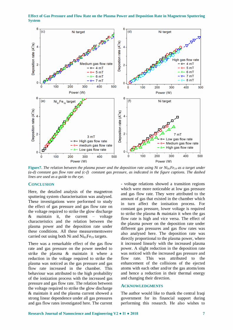
This variation might be due to the difference in
the atomic weight and size of the ejected atoms
of different materials. There is a slight reduction
in the deposition rate by increasing the gas
pressure and gas flow rates, especially at high
plasma power, as can be seen in Figure 7(c-d)
and Figure 7(e-f), respectively. This might be
due to the enhancement of the collisions of the
ejected atoms with each other or/and the gas
atoms/ions or due to the reduction of the thermal
energy of the sputtered atoms and changing their
direction and accordingly the deposition kinetics
are changed. Thus, the deposition rate can be
modified by changing the gas pressures, gas
flow rates and the plasma voltage applied
between the two electrodes.
Effect of Gas Pressure and Flow Rate on the Plasma Power and Deposition Rate in Magnetron Sputtering
System
Research Journal of Nanoscience and Engineering V2 ● I1 ● 2018 7
Figure7. The relation between the plasma power and the deposition rate using Ni or Ni81Fe19 as a target under
(a-d) constant gas flow rate and (c-f) constant gas pressure, as indicated in the figure captions. The dashed
lines are used as a guide to the eye.
CONCLUSION
Here, the detailed analysis of the magnetron sputtering system characterisation was analysed.
These investigations were performed to study
the effect of gas pressure and gas flow rate on the voltage required to strike the glow discharge
& maintain it, the current – voltage
characteristics and the relation between the
plasma power and the deposition rate under these conditions. All these measurementswere
carried out using both Ni and Ni81Fe19 targets.
There was a remarkable effect of the gas flow rate and gas pressure on the power needed to
strike the plasma & maintain it where a
reduction in the voltage required to strike the plasma was noticed as the gas pressure and gas
flow rate increased in the chamber. This
behaviour was attributed to the high probability
of the ionization process with the increased gas pressure and gas flow rate. The relation between
the voltage required to strike the glow discharge
& maintain it and the plasma current showed a strong linear dependence under all gas pressures
and gas flow rates investigated here. The current
- voltage relations showed a transition regions
which were more noticeable at low gas pressure
and gas flow rate. They were attributed to the amount of gas that existed in the chamber which
in turn affect the ionisation process. For
constant gas pressure, lower voltage is required to strike the plasma & maintain it when the gas
flow rate is high and vice versa. The effect of
the plasma power on the deposition rate under different gas pressures and gas flow rates was
also analysed here. The deposition rate was
directly proportional to the plasma power, where
it increased linearly with the increased plasma power. A slight reduction in the deposition rate
was noticed with the increased gas pressure and
flow rate. This was attributed to the enhancement of the collisions of the ejected
atoms with each other and/or the gas atoms/ions
and hence a reduction in their thermal energy and changing their direction.
ACKNOWLEDGMENTS
The author would like to thank the central Iraqi government for its financial support during
performing this research. He also wishes to

Effect of Gas Pressure and Flow Rate on the Plasma Power and Deposition Rate in Magnetron Sputtering
System
8 Research Journal of Nanoscience and Engineering V2 ● I1 ● 2018
express his deep sense of appreciation and many
thanks to Prof. Dr. Del Atkinson at Physics Department-University of Durham for his
valuable assistance throughout this and other
works. Throughout, John Dobson has given invaluable technical help, and the author thanks
him greatly for fixing the sputtering system
whenever a problem arose.
REFERENCES
[1] Stuart, R. V. "Vacuum technology, thin films
and sputtering: An introduction" Academic
Press, Inc., Ltd., London, 1983.
[2] Penning, F. M. "Electrical discharges in gases"
Philips Technical Library, Netherlands,
Holland, 1957.
[3] Chapman, Brian "Glow discharge processes
sputtering and plasma etching" John Wiley &
Sons, Inc., USA, 1980.
[4] Kiyotaka, Wasa & Shigeru, Hayakawa "Hand
book of sputter deposition technology principles: Technology and Applications"
Noyes Publications, New Jersey, USA, 1992.
[5] Murakami, M. & Birukawa, M. "Sputtering
gases and pressure effects on the
microstructure, magnetic properties and
recording performance of TbFeCo films "J.
Magn. Magn. Mater., 320, 5, 608–611, 2008.
[6] Ping He, William A. McGahan, S. Nafis, John
A. Woollam, Z. S. Shan, S. H. Liou F. Sequeda,
T. McDaniel & H. Do "Sputtering pressure
effect on microstructure of surface and
interface, and on coercivity of Co / Pt
multilayers" J. Appl. Phys., 70, 10, 1991.
[7] Whitacre, J. F., West, W. C. & Ratnakumar, B.
V. "The influence of target history and
deposition geometry on RF magnetron
sputtered LiCoO2 thin films" J. Pow. Sour.,
103, 134–139, 2001.
[8] Uehara, Y. & Ikeda, S. "Dependence of
Magnetic Properties on Sputtering Pressure for
Fe–Al–O Alloy Films Made by Carousel-Type
Sputtering" Jpn. J. Appl. Phys., 42, 1, 7A,
4297–4301, 2003.
[9] Kelly, P. & Arnell, R. "Magnetron sputtering:
A review of recent developments and
applications" Vacuum, 56(3), 159, 2000.
[10] Sultan, Musaab Salman "Thickness dependence
of magnetisation behaviour in sputtered Ni and
Ni81Fe19 thin films" to be submitted, 2018.


![Homemade an Atmospheric Pressure Cold Plasma Sterilization ... · plasma reactor shown in Fig. 1 [2]. By our DBD plasma at atmospheric pressure system, that can succeed in . E. coli](https://img.dokumen.tips/doc/110x75/6087616ab358a048a252f115/homemade-an-atmospheric-pressure-cold-plasma-sterilization-plasma-reactor-shown.jpg)