Embed Size (px)
Citation preview

Spray Height Controller
Summers (Main Lift & Enhanced Stability)
Installation Manual
SM03-4B

Printed in Canada Copyright 2009 by NORAC Systems International Inc. Reorder P/N: UC5-SM03-4B-INST Rev C (Summers Main Lift & Enhance Stability Option –
44962D)
NOTICE: NORAC Systems International Inc. reserves the right to improve products and their specifications without notice and without the requirement to update products sold previously. Every effort has been made to ensure the accuracy of the information contained in this manual. The technical information in this manual was reviewed at the time of approval for publication.

Contents
1 Introduction .....................................................................................................1
2 Kit Parts ...........................................................................................................2
3 Hydraulic Installation .....................................................................................5
4 Roll Sensor Installation ..................................................................................7
5 Electrical Installation ......................................................................................9
6 Software Setup ............................................................................................. 11
7 Cable Drawings ............................................................................................ 12

1
1 Introduction
Congratulations on your purchase of the NORAC UC5 Spray Height Controller. This system is manufactured with top quality components and is engineered using the latest technology to provide operating reliability unmatched for years to come.
When properly used the system can provide protection from sprayer boom damage, improve sprayer efficiency, and ensure chemicals are applied correctly.
Please take the time to read this manual completely before attempting to install the system. A thorough understanding of this manual will ensure that you receive the maximum benefit from the system.
Your input can help make us better! If you find issues or have suggestions regarding the parts list or the installation procedure, please don’t hesitate to contact us.
Every effort has been made to ensure the accuracy of the information contained in this manual. All parts supplied are selected to specially fit the sprayer to facilitate a complete installation. However, NORAC cannot guarantee all parts fit as intended due to the variations of the sprayer by the manufacturer.
Please read this manual in its entirety before attempting installation.

2
2 Kit Parts
2.1 Hydraulic Plumbing
Figure 1: SM03 Hydraulic Plumbing

3
2.2 List of Parts
The following tables list the Summers main lift and enhanced stability kit (SM03) specific parts of the NORAC UC5 system. This kit is to be used when installing the proportional main lift option with existing Summers installations that have a valve block that was purchased after December of 2010. These valve blocks require a 4-bolt expansion block.
Item Part Number Name Quantity
C03 43210-01 CABLE UC5 NETWORK 18 AWG 1M 1
C04 43210-03 CABLE UC5 NETWORK 18 AWG 3M 1
C10 43230-04 CABLE UC5 VALVE 2PIN DT TO 2PIN DT 2
E04 43741* UC5 ROLL SENSOR VER. 2 1
E10 43760 UC5 NETWORK COUPLER 3-WAY 1
E12 43764 UC5 NETWORK COUPLER 2-WAY 1
H01 44863-01 HOSE ASSEMBLY 122R2-06 36 IN L 6FJX 6FJX 1
H10 44865-50 HYDRAULICS FITTING KIT - SM3 1
M01 UC5-SM03-4B-INST MANUAL INSTALLATION UC5 MAIN LIFT OPTION SUMMERS - 44962D 1
V01 44962D VALVE ASSEMBLY EXPANSION DPOC PROP DT 4 BOLT 1
* For systems purchased BEFORE October 1, 2011, the roll sensor part number is 43740.

4
2.3 Hydraulic Fitting Kit Details (P/N: 44865-50)
Item Part Number Name Quantity Picture
F02 103839 TEE - 6FJXR 6MJT 1
F03 104369 PLUG - 6MBP 1
F04 103312 MALE ADAPTER - 6MB 6MJ 1
6 M B - 6 M OR X 90SIZE IN 1/16TH'S
GENDER: MALE OR FEMALE
90° ANGLESWIVELTYPEGENDERSIZE
TYPE:B - ORBJ - JICOR - FLAT FACEP - PIPE
Fitting Name Example:
The use of dielectric grease is not recommended on any NORAC electrical connections.
To ensure all stainless steel hardware does not gall or seize apply a light coating of the supplied Permatex Anti-seize grease to all threaded parts upon installation. Permatex Anti-seize lubricant is preferred, but other similar anti-seize products may be used.

5
3 Hydraulic Installation
Ensure all pressure has been bled from the system before disconnecting any lines or fittings. Hydraulic pressure will exist on the main lift circuit unless the main lift is all the way down.
Component failure due to oil contamination is not covered under the NORAC UC5 system warranty. It is recommended that a qualified technician perform the hydraulic installation.
1. Use Figure 1 as a reference for installing the hydraulics.
2. Loosen the existing 2-station valve block so that it can be moved and/or twisted for the installation of the expansion block.
3. Remove the four 4MBP plugs from the 2 station valve block (Figure 2).
4. Coat the four o-rings in hydraulic oil and install them into the expansion block. Ensure the o-rings are seated properly.
5. Attach the expansion block to the 2 station block using the included spring washers and bolts.
6. Tighten the bolts to 31 ft-lbs.
Figure 2: NORAC Expansion Block Assembly

6
7. Remove all plastic plugs from the NORAC expansion valve block (V01).
8. Install the 6MB 6MJ fitting (F04) into the “B” port of the expansion block.
9. Install the 6MBP plug (F03) into the “A” port of the expansion block.
10. If the valve block is not already installed on the sprayer, install it as outlined in the UC5 Spray Height Control installation manual.
11. Attach hose H01 to the “B” port on the expansion block. Route the free end of the hose to the Summers valve block.
12. Tee in H01 to the existing main lift line on the Summers valve block, using the tee fitting (F02).
You must ensure no hydraulic components will interfere with any sprayer parts or be pulled tight at any time.
7
4 Roll Sensor Installation
All roll sensors must be part number 43741. If the previously installed roll sensors are part number 43740, they must be replaced by 43741 before proceeding with this installation.
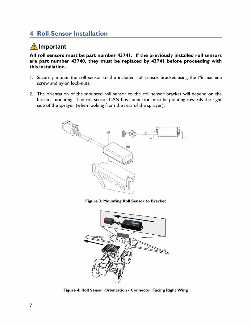
1. Securely mount the roll sensor to the included roll sensor bracket using the #6 machine screw and nylon lock-nuts.
2. The orientation of the mounted roll sensor to the roll sensor bracket will depend on the bracket mounting. The roll sensor CAN-bus connector must be pointing towards the right side of the sprayer (when looking from the rear of the sprayer).
Figure 3: Mounting Roll Sensor to Bracket
Figure 4: Roll Sensor Orientation - Connector Facing Right Wing

8
3. The roll sensor is to be mounted onto the chassis as shown in Figure 5. Ensure the roll sensor is relatively level when chassis is level.
Figure 5: Chassis Roll Sensor Mounting
4. Ensure that the chassis roll sensor (Figure 5) has the highest serial number and that the boom frame roll sensor (previously installed) has the lowest serial number (Figure 6).
Figure 6: Boom Frame and Intermediate Frame Roll Sensors (Previously Installed)
5. Ensure roll sensors are mounted adequately and that the cables provide enough slack to allow sufficient boom roll.
Intermediate Frame Roll
Sensor
Boom Frame Roll Sensor
9
5 Electrical Installation
1. Locate the valve module installed on the NORAC valve block.
2. Remove the plugs installed in positions 5 and 6.
3. Connect the 2 pin connector on cables C10 into positions 5 and 6 on the valve module.
4. Connect the other end of cables C10 to the 2 pin connectors on the NORAC expansion block (V01).
5. Remove the existing cable C03 from the existing input module. Connect the unplugged connector from existing cable C03 into the 3-way coupler (E10).
6. Connect one end of cable C03 to the existing input module and the other end to the 3-way coupler (E10).
7. Connect one end of cable C04 to the 2-way coupler (E12) and the other end to the 3-way coupler (E10).
8. Connect the cable from the Roll Sensor (E04) to the other end of the 2-way coupler (E12).
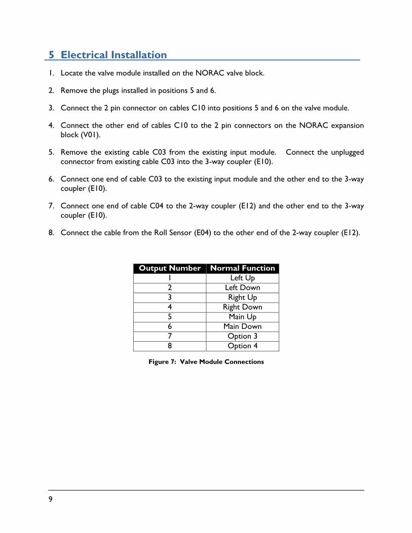
Figure 7: Valve Module Connections
Output Number Normal Function 1 Left Up 2 Left Down 3 Right Up 4 Right Down 5 Main Up 6 Main Down 7 Option 3 8 Option 4

10
Figure 8: Electrical Connections
Only the components shown in black are included in this kit.

11
6 Software Setup
1. Start up your sprayer and test the sprayer’s functionality. The display terminal does not need to be powered on for the original switches to function.
Confirm that the cabling and hoses are agreeable to the entire range of motion.
2. If any functions do not work, review the hydraulic and electrical portions of this manual to check for proper installation.
3. Turn on the power for the display terminal using the switch on the side.
4. Refer to the UC5 Spray Height Control Operator’s Manual to run an automatic install with the “Summers Main Lift Option” type selected.

12
7 Cable Drawings
7.1 ITEM C10: 43230-04 – CABLE UC5 VALVE DT TO DT
7.2 ITEM C03: 43210-01 - CABLE UC5 NETWORK 18 AWG - 1M

13
7.3 ITEM C04: 43210-03 - CABLE UC5 NETWORK 18 AWG - 3M

Canada NORAC Systems International Inc.
Phone: (+1) 306 664 6711 Toll Free: 1 800 667 3921
Shipping Address: 3702 Kinnear Place
Saskatoon, SK S7P 0A6
United States NORAC, Inc.
Phone: (+1) 952 224 4142 Toll Free: 1 866 306 6722
Shipping Address: 6667 West Old Shakopee Road, Suite 111
Bloomington, MN 55438
Europe NORAC Europe
Phone: (+33) (0)4 26 47 04 42 Shipping Address:
Rue de l’hermitage 01090 GUEREINS
France
www.norac.ca