Embed Size (px)
Citation preview

SPLATSmall robotic Platforms for Limited Access
Terrain
Project Sponsor: Eglin Air Force Base Munitions Directorate Air Force Research Laboratory
Contact: Mr. Jeffrey Wagener
Team # 5:Jeffrey Dalisay
Michael GenoveseIvan Lopez
Ryan Whitney

2
Statement of Need/Problem Definition
• In order to collect accurate and sufficient intelligence, there is a need for small platforms that can maneuver on both horizontal and vertical surfaces. Design subsystems that would allow a small robotic platform to:
– Transition between horizontal and vertical planes
– Translate vertically a minimum of 5ft
– Remain on the vertical plane for 30 minutes
– Be confined by a box no bigger than 6”x6”x6”
3
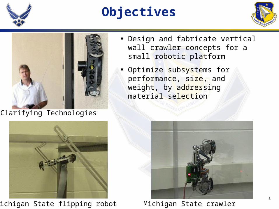
Objectives
• Design and fabricate vertical wall crawler concepts for a small robotic platform
• Optimize subsystems for performance, size, and weight, by addressing material selection
Michigan State crawler
Clarifying Technologies
Michigan State flipping robot
4
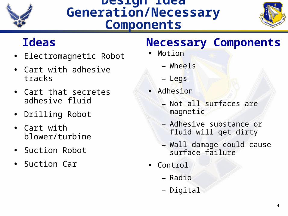
• Motion
– Wheels
– Legs
• Adhesion
– Not all surfaces are magnetic
– Adhesive substance or fluid will get dirty
– Wall damage could cause surface failure
• Control
– Radio
– Digital
Design Idea Generation/Necessary Components
• Electromagnetic Robot
• Cart with adhesive tracks
• Cart that secretes adhesive fluid
• Drilling Robot
• Cart with blower/turbine
• Suction Robot
• Suction Car
Ideas Necessary Components

5
Concept 1: Cart w/ Blower
Thrust from the blower will force the cart against the wall, and the wheel in front will help the transition between the floor and wall.
6
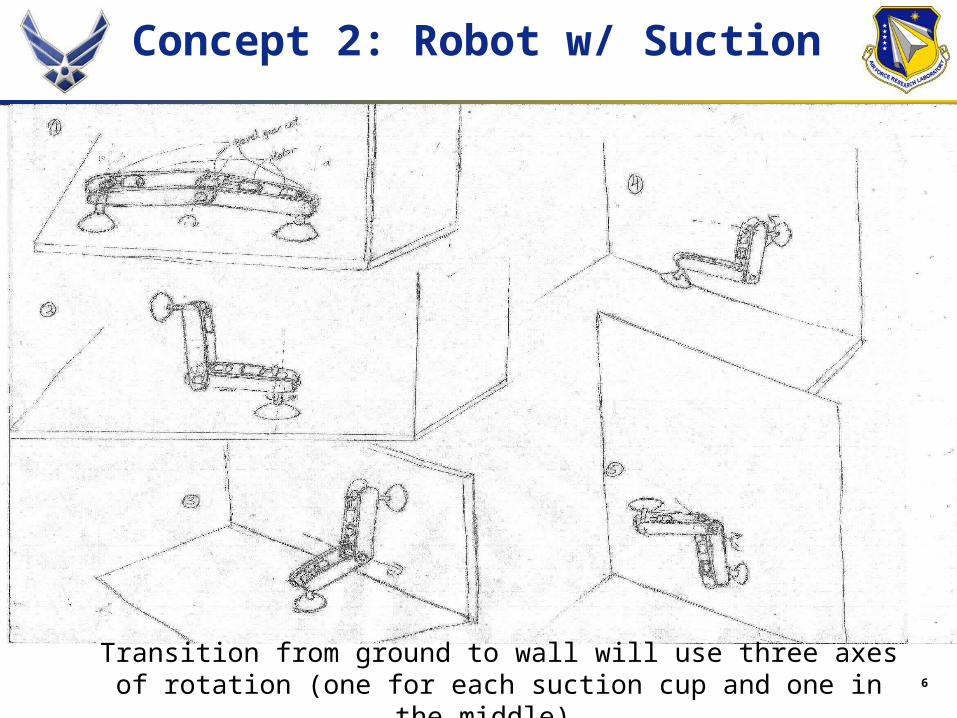
Concept 2: Robot w/ Suction
Transition from ground to wall will use three axes of rotation (one for each suction cup and one in the middle).

7
Concept 3: Suction Car
8
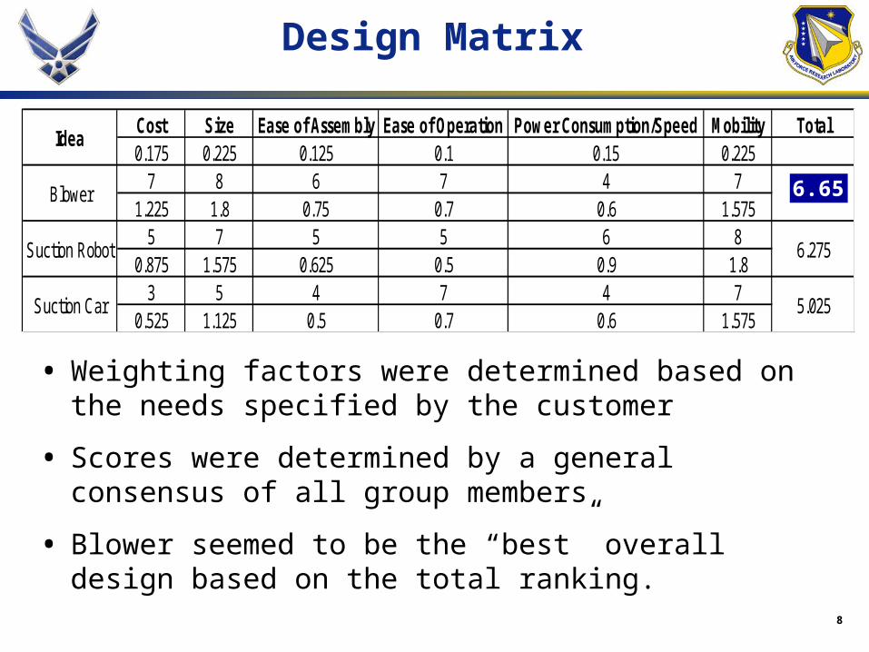
Cost Size Ease of Assembly Ease of Operation Power Consumption/Speed Mobility Total0.175 0.225 0.125 0.1 0.15 0.225
7 8 6 7 4 71.225 1.8 0.75 0.7 0.6 1.575
5 7 5 5 6 80.875 1.575 0.625 0.5 0.9 1.8
3 5 4 7 4 70.525 1.125 0.5 0.7 0.6 1.575
6.65
6.275
5.025
Idea
Blower
Suction Robot
Suction Car
Design Matrix
• Weighting factors were determined based on the needs specified by the customer
• Scores were determined by a general consensus of all group members
• Blower seemed to be the “best” overall design based on the total ranking.
6.65
9
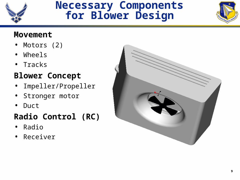
Necessary Componentsfor Blower Design
Movement• Motors (2)
• Wheels
• Tracks
Blower Concept• Impeller/Propeller
• Stronger motor
• Duct
Radio Control (RC)• Radio
• Receiver

10
Radio Control
4/6 Channel Transmitter
• 1 channel for each motor (3)
• Extra channels for possibility of added components
Receiver
• 1 port for each channel
• Connects transmitter to motor
Speed Controls
• 1 for brushless motor
11
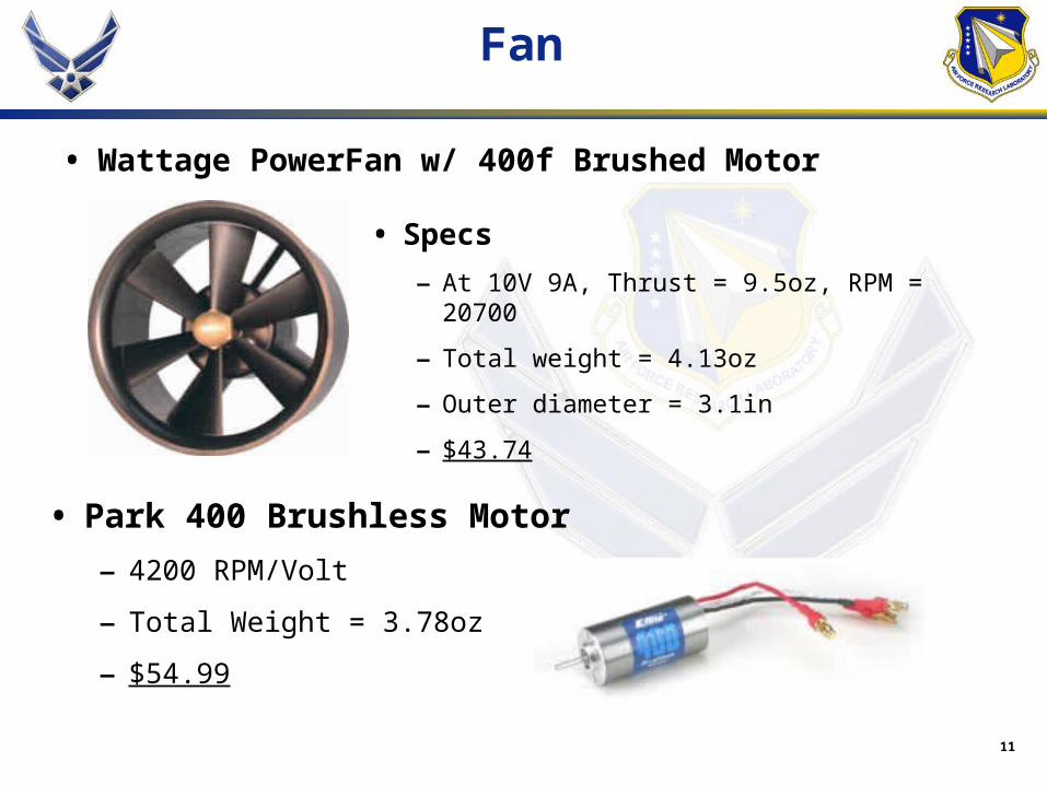
Fan
• Wattage PowerFan w/ 400f Brushed Motor
• Park 400 Brushless Motor
– 4200 RPM/Volt
– Total Weight = 3.78oz
– $54.99
• Specs
– At 10V 9A, Thrust = 9.5oz, RPM = 20700
– Total weight = 4.13oz
– Outer diameter = 3.1in
– $43.74
12
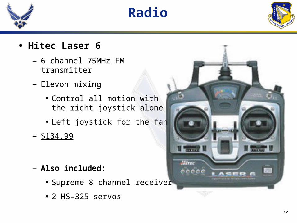
Radio
• Hitec Laser 6
– 6 channel 75MHz FM transmitter
– Elevon mixing
• Control all motion with the right joystick alone
• Left joystick for the fan
– $134.99
– Also included:
• Supreme 8 channel receiver
• 2 HS-325 servos
13
Body: Fiberglass
Fiber
• Mat
– Resin distributes by itself
– Unorganized fibers
– ~$2.50/yard (1yd by 38”)
• Cloth
– Patterned (squares)
– Must work resin in more thoroughly
– Isotropic Properties
– ~$5/yard
Resin
• Polyester
– Cheap
– Relatively strong
– ~$10/Quart
• Epoxy
– Higher Strength
– Bonds to metal
– ~$20/Quart
14
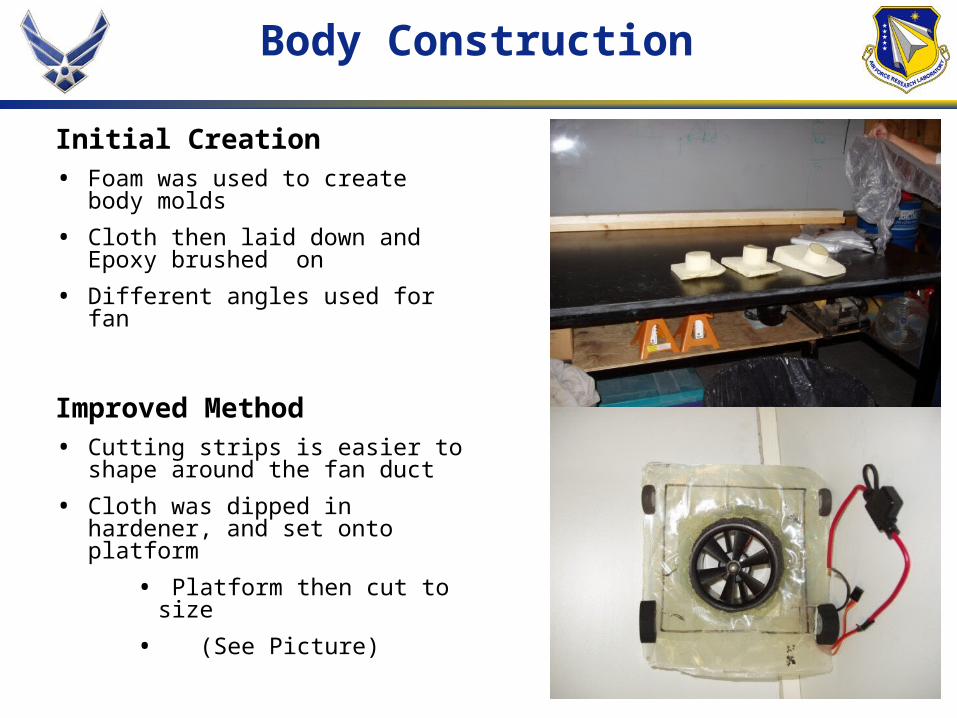
Body Construction
Initial Creation• Foam was used to create body
molds
• Cloth then laid down and Epoxy brushed on
• Different angles used for fan
Improved Method• Cutting strips is easier to shape
around the fan duct
• Cloth was dipped in hardener, and set onto platform
• Platform then cut to size
• (See Picture)

15
Fan Testing
Motor Characteristics
- Power(Voltage,Current)
-Thrust(Power)

16
Initial Results
Thrust vs. Power
0
24
68
1012
14
0 20 40 60 80 100 120 140
Power (W)
Th
rust
(o
z)
400f Brushed Motor
Park 400 SeriesBrushless Motor
Thrust vs. Power of both the Brushed and Brushless 400 motors
Points from Fan/Motor Manual

17
Drivetrain
• Attaching the axles
– Plastic braces for support, and then glued to body
– Wheels put on, and axle tips burned
• Motors
– Brushless were first used
• Needed to handle 12V
• Too heavy(1.6oz each), too much speed
– Servos then purchased
• Made continuous
• Lightweight (.6oz each)
18
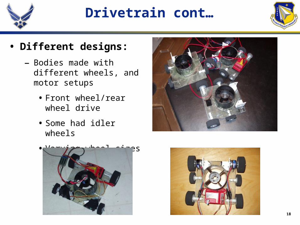
Drivetrain cont…
• Different designs:
– Bodies made with different wheels, and motor setups
• Front wheel/rear wheel drive
• Some had idler wheels
• Varying wheel sizes to change ground clearance

19
Optimizing Traction
• Maximize friction without overloading the motors
• Numerous treads were tested
– Electrical, Double sided, and waterproof tape
– Rubber bands
– Spray Adhesive
20
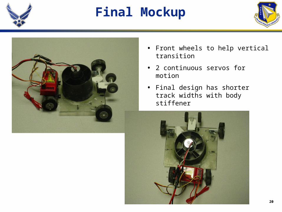
Final Mockup
• Front wheels to help vertical transition
• 2 continuous servos for motion
• Final design has shorter track widths with body stiffener

21
Final Design
22
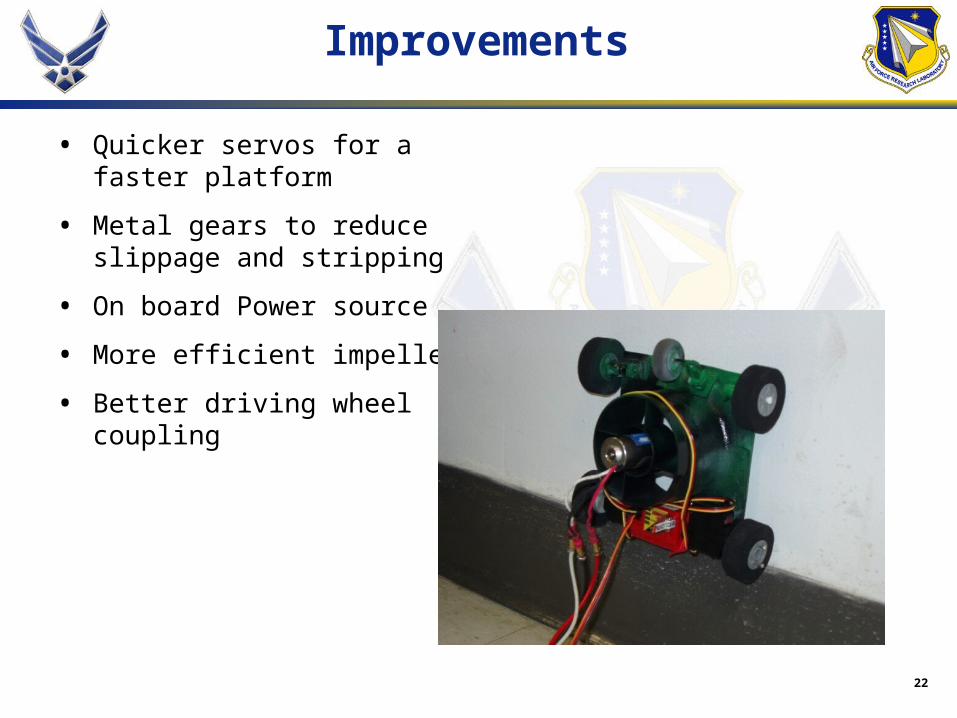
Improvements
• Quicker servos for a faster platform
• Metal gears to reduce slippage and stripping
• On board Power source
• More efficient impeller
• Better driving wheel coupling

23
Acknowledgments
• Mr. Jeffrey Wagener and Dr. Joel House: Contact/Sponsor at Eglin Air Force Base
• Jeff Radkins: Owner of Hobbytown USA
• Kyle: Global Hobby
• Jon Cloos: Purchase Orders
• Dr. Luongo
• SAE Club for fiberglass help