Embed Size (px)
Citation preview

SPEED SENSOR SIMULATOR BOX Bachelor thesis in Electrical Engineering
HERMANSSON, EMIL SERTI, TOMAS
Department of Signals and Systems CHALMERS UNIVERSITY OF TECHNOLOGY Gothenburg, Sweden 2015


Preface The thesis work covers 15 credits and has been performed at the Department of Signals and Systems at Chalmers University of Technology. It is the final step in the education of Electrical Engineering, 180 credits. The thesis work took place at Volvo Powertrain where a Speed Sensor Simulator Box was designed during 10 weeks of the spring term 2015.
We would like thank our mentor at school, Manne Stenberg, for his dedication during the project and our supervisor at Volvo Powertrain, Erik Svangård, for making this thesis work possible. We would also like to express our gratitude to our mentor at Volvo Powertrain, Agne Holmqvist, which during the project has given us support, advice and shown great commitment. Furthermore, we would like to thank the remaining employees who contributed with help and support, but also to a good atmosphere at the workplace.
At last, we would like to acknowledge ArduinoTM licenses and thank them for letting us use images of original ArduinoTM boards, under the circumstances that we use the TradeMark sign every time ArduinoTM is mentioned.
Emil Hermansson & Tomas Serti Gothenburg, 2015


Abstract Volvo is today one of the largest truck manufacturers in the world and an important part of the truck engine is the engine control module. The engine control module is in constant development and needs to be tested regularly. This development takes place at Volvo Powertrain where tests and measurements are performed on engine control modules. Since Volvo Powertrain is in need of a Speed Sensor Simulator Box, the purpose of this thesis work has been to create such a product. The Speed Sensor Simulator Box shall be used at tests and measurements of engine control modules and be able to generate speed signals that mimic the signals being generated from cam- and crankshaft sensors in real truck engines.
The project was performed at Volvo Powertrain where software as well as electronic hardware was designed. The software was developed in ArduinoTM and manages the signal generation, while the electronic hardware receives and processes the generated signals. The result was presented in a box that either can run standalone or be controlled by a computer. The Speed Sensor Simulator Box is equipped with a display that shows the current speed and a rotating potentiometer that can adjust the speed. When the unit is controlled by computer, the serial interface is built upon simple menus and the number of functions increases as displacements can be made between the cam- and crankshafts.
Due to time limits, some limitations have been made where the most significant have been included in the project. Focus has been on creating a product that can generate cam- and crank signals with sufficient resolution, signal synchronization and fault injection. Furthermore, the unit should be galvanic isolated from the engine control module and the speed should be presented on a display.


Sammanfattning Volvo är idag en av världens största lastbilstillverkare och en viktig del i lastbilsmotorn är motorstyrenheten. Motorstyrenheten är i ständing utveckling och måste regelbundet testas. Denna utveckling sker på Volvo Powertrain där tester och mätningar utförs på motorstyrenheter. Då Volvo Powertrain är i behov av en varvtalssimulatorlåda så har syftet med detta examensarbetat varit att skapa en sådan produkt. Varvtalssimulatorlådan skall användas vid tester och mätningar på motorstyrenheter och kunna generera varvtalssignaler som efterliknar de signaler som genereras från kam- och vevaxelgivare i verkliga lastbilsmotorer.
Projektet utfördes på Volvo Powertrain där mjukvara samt elektronikhårdvara konstruerades. Mjukvaran utvecklades i ArduinoTM och ansvarar för signalgenereringen, medan elektronikhårdvaran tar emot och bearbetar de genererade signalerna. Resultatet presenterades i en låda som antingen kan drivas fristående eller styras via en dator. Varvtalssimulatorlådan är utrustad med en display som visar det aktuella varvtalet och en roterande potentiometer som kan justera varvtalet. När enheten styrs via dator så är det seriella gränssnittet uppbyggt ev enkla menyer och antalet funktioner ökar då förskjutningar kan göras mellan kam- och vevaxlarna.
På grund av tidsbrist har vissa avgränsningar gjorts där det mest väsentliga har inkluderats i projektet. Fokus har legat på att skapa en produkt som kan generera kam- och vevaxel-signaler med tillräcklig upplösning, signalsynkronisering och felinjicering. Dessutom skulle enheten galvaniskt avskiljas från motorstyrenheten och varvtalet skulle presenteras på en display.


Table of Contents List of abbreviations .................................................................................................................................... 1
1. Introduction ......................................................................................................................................... 2
1.1. Background ................................................................................................................................... 2
1.2. Purpose.......................................................................................................................................... 2
1.3. Delimitations ................................................................................................................................ 3
1.4. Definition of task ......................................................................................................................... 3
1.5. Specification ................................................................................................................................. 3
2. Technical background ......................................................................................................................... 4
2.1. Cam- and crankshaft ................................................................................................................... 4
2.2. Variable reluctance sensor .......................................................................................................... 6
2.3. SIMetrix ......................................................................................................................................... 6
2.4. ArduinoTM ..................................................................................................................................... 6
2.4.1. ArduinoTM software ............................................................................................................. 7
2.4.2. ArduinoTM hardware ............................................................................................................ 7
2.4.3. Druid4Arduino .................................................................................................................... 7
2.5. Hardware ....................................................................................................................................... 8
2.5.1. Potentiometers ..................................................................................................................... 8
2.5.2. Liquid Crystal Display ........................................................................................................ 8
2.5.3. Transformers ........................................................................................................................ 8
2.5.4. DC/DC-converter .............................................................................................................. 8
2.5.5. Operational amplifiers and buffers ................................................................................... 8
3. Implementation ................................................................................................................................. 10
3.1. Preliminary learning ................................................................................................................... 10
3.2. Simulations.................................................................................................................................. 10
3.3. Software ...................................................................................................................................... 12
3.3.1. Ardu-Stim ........................................................................................................................... 12
3.3.2. Signal generation................................................................................................................ 12
3.3.3. Interrupt service routines and Timers ............................................................................ 13
3.3.4. Potentiometer and LCD ................................................................................................... 14
3.3.5. Seriul UI .............................................................................................................................. 15
3.4. Measurements ............................................................................................................................ 15
3.5. Product structure ....................................................................................................................... 16
4. Alternative solutions ......................................................................................................................... 18

5. Results ................................................................................................................................................. 19
5.1. Simulations results ..................................................................................................................... 19
5.1.1. Simulation 1........................................................................................................................ 19
5.1.2. Simulation 2........................................................................................................................ 19
5.2. Software results .......................................................................................................................... 20
5.2.1. Calculations ........................................................................................................................ 20
5.2.2. Construction of wheel patterns ....................................................................................... 21
5.2.3. Serial UI .............................................................................................................................. 22
5.3. Measurement results .................................................................................................................. 23
5.3.1. Measurement 1 .................................................................................................................. 23
5.3.2. Measurements 2 ................................................................................................................. 23
5.4. Test and verification .................................................................................................................. 23
6. Discussion and conclusion ............................................................................................................... 26
Bibliography ................................................................................................................................................ 27
Appendices .................................................................................................................................................... 1
Appendix A – Schematic ........................................................................................................................ 1
Appendix B – Specification from Volvo .............................................................................................. 2
Appendix C – Volvo MD13 with EGR ............................................................................................... 3
Appendix D – Modified Ardu-Stim program code ............................................................................ 5
Appendix D.1 – ardustim.ino ............................................................................................................ 5
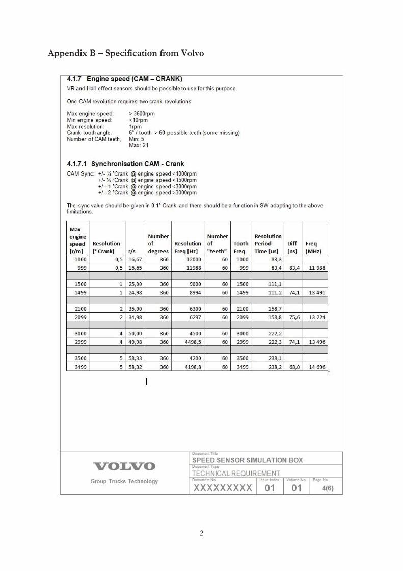
Appendix D.2 – ardustim.h ............................................................................................................. 12
Appendix D.3 – defines.h ................................................................................................................ 12
Appendix D.4 – enums.h ................................................................................................................. 12
Appendix D.5 – serialmenu.cpp ..................................................................................................... 13
Appendix D.6 – serialmenu.h .......................................................................................................... 16
Appendix D.7 – structures.h ........................................................................................................... 17
Appendix D.8 – wheel_defs.h ......................................................................................................... 17


1
List of abbreviations DAC Digital-to-analog converter
DC Direct current
ECM Engine control module
EGR Exhaust gas recirculation
GUI Graphical user interface
I/O Input/output
IDE Integrated development environment
ISR Interrupt service routine
LCD Liquid crystal display
PLL Phase-locked loop
PWM Pulse width modulation
RPM Revolutions per minute
UI User interface
VR Variable reluctance

2
1. Introduction
1.1. Background Volvo built its first truck in 1928 and is today one of the largest and leading manufacturers of heavy trucks in the world [1]. A large part of technical development takes place within the Volvo Group Trucks Technology where research, engine development and purchasing activity are important aspects [2].
Within Volvo Powertrain, tests and measurements are performed for the development of ECM’s. The ECM is constantly developed to increase performance, safety and improve the environment [2]. Since it controls several functions in the engine, the ECM is an important part of the vehicle and needs to be tested regularly.
One of the fundamental keys to a working ECM is sensing the positions of the cam- and crankshafts. If the ECM does not know the angle of the cam- and crankshafts, it has no idea when to inject fuel to the engine. The ECM gets this information using a set of sensors to detect the position of the cam- and crankshafts as they rotate. These sensors consist of a magnet which detects when a gear tooth passes and a signal is then being generated to the ECM [3]. To facilitate tests and measurements on ECM’s, Volvo Powertrain is in need of a Speed Sensor Simulator Box that can generate speed signals similar to those the cam- and crankshaft sensors create.
1.2. Purpose The purpose is to design a Speed Sensor Simulator Box that can be used at tests and measurements of ECM. The unit should be able to generate speed signals similar to those obtained from real sensors for cam- and crankshafts in truck engines, as well as having the possibility of fault injection. Fault injection can either mean missing teeth or incorrect sync between two signals.
The project consists of both hardware and software and is based on the interaction between them. To generate the desired signals and signal synchronization, software is developed through ArduinoTM. Electronic hardware is built for signal conversion and adaption to the existing ECM’s of Volvo Powertrain. A successful product would result in facilitated tests and measurements.

3
1.3. Delimitations Due to time limitation, delimitations have been made where focus is on:
Generating cam and crank speed signals equal to the ones being generated from VR sensors in real engines.
Sufficient resolution, signal synchronization and fault injection. Designing electronic hardware where the signals are processed as well as galvanic isolated
from the ECM. Creating a box with a panel that contains a display and speed regulation.
1.4. Definition of task To achieve as good result as possible, the following questions need to be answered:
How should the signal generation be done? Which components are required for the electronic hardware?
How should the ECM be galvanic isolation from the circuit? How should the software be written to receive the desired signals? How should the product be structured?
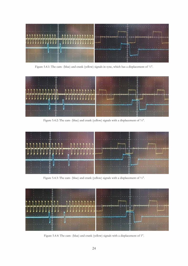
1.5. Specification Before the start of the project some specifications were made, see Appendix B and C. These specifications were:
The signals should be based on a Volvo MD13 engine with EGR. The crank signal should consist of 60-2-2-2 gear teeth per crank revolution, which means
that one crank revolution consists of 60 gear teeth with two missing gear teeth at three different occasions.
The cam signal should consist of 6+1 gear teeth per crank revolution, which means that one cam revolution consists of 6 gear teeth plus an extra gear tooth that is used for positioning.
One cam revolution requires two crank revolutions. The engine speed should be adjustable within the range of 10-3600 RPM. Signal synchronization and displacements between the cam and crank signals should be
able to be selected with an accuracy of ¼°, ½°, 1° or 2°. The displacements are made with consideration to the synchronized signal, which has a cam displacement of ½°.
Engine speed in RPM should be demonstrated on a display.
4
2. Technical background
2.1. Cam- and crankshaft An important part of the cam mechanism is the camshaft where a rotating metal shaft converts rotating motions into reciprocating motions. The rotating shaft has one or more lobes that control cam followers as they rotate [4]. The lobes are usually circular with an extra convex side which makes them push and return the cam followers as the shaft rotates, see Figure 2.1.1. A cam follower can either be a sliding surface or a roller.
Figure 2.1.1: The camshaft [5].
Camshafts are often used when linear motions are desired, e.g. in regulating valves. As the camshaft rotates, the intake and exhaust valves are opened and closed by the lobes in time with the motion of the piston. For the valves to open at the right pace and at the right angle, it is required that the camshaft is synchronized with the crankshaft [6].
The crankshaft, which basically is the opposite of the camshaft, converts reciprocating motions into rotating motions and is often used to drive a wheel [7]. It is comprised of a long piece of metal in a specific shape and consists of a shaft with one or more crankpins that are connected to a piston rod. The piston rod is further connected to a piston and as the piston moves back and forth, the rod provides rotating motions to the crankshaft. The piston is located inside a cylinder and the volume that is created between the piston and the cylinder head is called combustion chamber. During combustion process, pressure is increased in the chamber and a force is generated which causes movement in the piston and thereby the crankshaft [8]. At one end of the crankshaft, a flywheel is attached whose purpose is to store the energy from particular firings. This is for the engine to run more smoothly [9]. Figure 2.1.2 shows an overview of the crankshaft.

5
Figure 2.1.2: The crankshaft [8].
In an engine, the timing between the valves and the pistons is critical. It is important that the intake and exhaust valves are opened and closed at the right time; otherwise it could lead to the engine running badly or self-destruction when the valves and the pistons make contact [10]. The cam- and crankshafts are connected to each other by either gear transmission, or by being connected via a belt or a chain, see Figure 2.1.3.
In a four-stroke engine, two complete crankshaft revolutions are made per four-stroke cycle. During this time, the valves are opened and closed only once. Since the valves are operated by the camshaft, the camshaft completes only one revolution per cycle. Thereby, the camshaft is rotating at half the speed of the crankshaft [10].
Figure 2.1.3: The cam- and crankshafts connected by a belt [5].

6
2.2. Variable reluctance sensor To know the angle positions of the cam- and crankshafts in a truck engine, it is required that the ECM receives the information. This information is given by one or more sensors, where one of the most common types is the VR sensor.
The VR sensor is built of a permanent magnet with a wire wound around it. Current is induced when the ferrous material from a gear tooth passes the magnet. Since the magnetic field is altered when this happens, it leads to an electrical voltage. When the gear tooth moves further away from the magnetic field, the voltage gets an opposite flux. This leads to a time-varying sinusoidal signal that the ECM processes [11], see Figure 2.2.1.
Figure 2.2.1: VR sensor detecting a gear tooth [12].
The ECM transduces the sinusoidal signal into a digital signal that can be more easily read than an analog signal. Each period of the signal corresponds to a gear tooth and with the help of an evaluation from the ECM, the engine speed in RPM as well as the information about where in the cycle the engine is at the time can be determined [11].
2.3. SIMetrix SIMetrix is a simulation program where analog and mixed signals can be simulated. The program contains functions which allow the user to build up own electrical circuits to get an idea of how they could act in reality. The ability to simulate in this way makes it easier for the user to test circuits and knowing which components that might be appropriate. From the simulations it is possible to get analog and mixed signals which can be displayed in either waveforms or different sweep [13].
2.4. ArduinoTM ArduinoTM is an open-source hardware microcontroller board which is intended to make the use of electronics more accessible. The hardware consists of a simple circuit design, while the software consists of a programming language, a compiler and a boot loader running on the board [14].
When using ArduinoTM, interactive objects can be developed. However, it can also be used to receive input signals from different switches and sensors, as well as controlling lights, motors and other physical outputs. ArduinoTM projects can either be standalone or communicate with software running on the computer [15].

7
2.4.1. ArduinoTM software An ArduinoTM project or code is called a “sketch” and is written in either C or C++. In this project the programming is performed in ArduinoTM IDE, which is a cross-platform application written in Java. It is designed to easily introduce newcomers that usually are unfamiliar with software development [14].
To make input and output operations much easier, the ArduinoTM IDE uses a software library called “Wiring”, which is an open-source programming framework [16]. As a result of this, the user only needs to define the following two functions to make an executable program:
setup() – a function that can initialize settings and that runs once at the start. loop() – a function that runs repeatedly [14].
2.4.2. ArduinoTM hardware The ArduinoTM boards consist of Atmel AVR microcontrollers with complementary components that facilitate programming as well as integration with other circuits. Different versions of ArduinoTM boards have been created where the ArduinoTM Uno and the ArduinoTM Mega are the most common ones [14]. In this project an ArduinoTM Uno is used.
The ArduinoTM Uno board uses an Atmega328 chip from the megaAVR series. It has 14 digital I/O pins where 6 of them can be used as PWM outputs. In addition, the board has 6 analog inputs, a 16 MHz ceramic resonator, a reset button, a USB connection and a power jack where 7-12 V are recommended as input voltage [17]. Furthermore, the board also has outputs pins that deliver 5 V, 3.3 V and ground, see Figure 2.4.2.1.
Figure 2.4.2.1: ArduinoTM Uno [17].
2.4.3. Druid4Arduino As previously mentioned in section 2.4, ArduinoTM projects can either be standalone or communicate with software running on the computer. An example of such software is Druid4Arduino, which is a program that can interact with SerialUI-based ArduinoTM projects through a simple GUI with menus. By connecting a USB-A cable to the ArduinoTM board, Druid4Arduino will connect to the ArduinoTM project and create the commands and menus defined in the sketch [18].

8
2.5. Hardware This section describes the electronic hardware that is used in the project. To know how the different components are connected to each other, see Appendix A.
2.5.1. Potentiometers A potentiometer is an adjustable resistance. The circuit contains two potentiometers of type 3540S-1-103L which has a resistance of 10 kΩ [19]. One is used for regulating the backlight of the LCD and the other is used for setting the RPM of the signals. By turning a sliding contact back and forth, the resistance can be regulated. Based on the voltage level being controlled by the resistance, an analog value is read into the ArduinoTM [20]. This value determines the RPM and prints it on the display.
2.5.2. Liquid Crystal Display The LCD being used is an ATM1602B [21]. It can fit 2x16 characters and has a blue backlight which is adjustable by a potentiometer.
The only thing shown on the display is the actual RPM. As the backlight, the RPM value is also adjustable by a potentiometer. Since revolutions over 3600 RPM are not needed, there is no way to exceed this value. In other words, the RPM showed on the display stops at 3600 RPM even if the potentiometer is being rotated.
2.5.3. Transformers The circuit contains two transformers of type THD 6235.0 [22]. Through electromagnetic induction, a transformer converts electrical energy between current- and voltage levels [23].
One transformer is being used for the cam signal and the other is being used for the crank signal. The secondary winding of each transformer is connected to the ECM which receives and processes the generated signals. The transformers galvanic isolate the ECM from the rest of the circuit.
2.5.4. DC/DC-converter A DC/DC-converter converts a source of DC from one voltage level to another [24]. The type being used is a TEN 5-2422WI from Traco Power and its purpose is to power the circuit as well as the ArduinoTM board in standalone mode [25]. The DC/DC-converter can handle input voltages within the range of 9-36 VDC and provides an output voltage of ±12 VDC. This is a safety for other components since it only supplies 12 V even if higher or lower voltages are being supplied.
2.5.5. Operational amplifiers and buffers An operational amplifier and two buffers are contained in the circuit. The operational amplifier is a voltage amplifier of type LM324N and it contains four operational amplifiers in the same device [26]. However, only two operational amplifiers are being used, one for the cam signal and one for the crank signal.

9
The buffers used are of type BUF634P [27]. As the operational amplifiers, one buffer is being used for the cam signal and the other is being used for the crank signal.
The operational amplifier and the buffer are intended to work as a voltage follower in order to increase the power to the transformer, see Figure 2.5.5.1.
Figure 2.5.5.1: The voltage follower.

10
3. Implementation
3.1. Preliminary learning To be able to create a Speed Sensor Simulator Box that generates cam and crank signals, it was necessary to know how the cam- and crankshafts operate and interact. Through the mentor at Volvo as well as research on the internet, this information was given in both texts and figures.
Since the idea behind the project was to generate the signals through ArduinoTM, a lot of knowledge needed to be obtained within that area. This was mainly done by a set of tutorials where fundamental knowledge was declared [28]. Furthermore, a lot of good information and examples were given at the homepage of ArduinoTM [29]. During the time of learning, practical tasks were performed where programming code were compiled and uploaded to the ArduinoTM board.
After further research on the internet as well as a proposal from the mentor at Volvo, an appropriate open-source program code called Ardu-Stim was found [30]. It is an ArduinoTM Uno based cam and crank wheel pattern generator developed to test how different ECM’s respond to cam and crank signals. As this was free to use and modify under the terms of the GNU General Public License, major parts of the preliminary learning was spent on reviewing the code in order to be able to modify the parts that was necessary for the project [31].
3.2. Simulations To be able to determine which components the electronic hardware should consist of, the program SIMetrix was used to simulate circuits in theory. As the signals from the ArduinoTM board are digital and within the range of 0-5 V, similar signals tried to be created. Since Ardu-Stim transmits cam- and crank signals on one pin each, a source that generates a 5 V digital signal was used. The signal was further connected to an operational amplifier used as a voltage follower to get lower output impedance and minimizing the risk of interference without affecting the voltage level of the signal.
In order to get galvanic isolation between the ECM and the rest of the circuit, a transformer was connected the output of the voltage follower, see Figure 3.2.1. Galvanic isolation means that the two sides are being isolated from each other to prevent undesired currents from flowing between the ECM and the signals of the circuit. [32]. Another benefit is that the transformer lowers the signal and creates the desired zero-crossing, which means that the signal is symmetrical around 0 V. Simulation 1 in Results shows the result of the simulated circuit with one source.

11
Figure 3.2.1: The simulated circuit with one source.
To make the generated signals more similar to the signals being generated from VR sensors in real engines, an additional source that generates a 5 V digital signal was added. Having two sources opens the possibility of a third voltage level between 0 V and 5 V. When one source is high and one source is low, the voltage level will be at 2.5 V. This voltage level corresponds to “idle” and occurs between different gear teeth as well as when a gear tooth is missing. In the previous circuit where only one source were used, this “idle” level did not exist and a missing gear tooth would simply be registered as 0 V, see Figure 3.2.2.
Figure 3.2.2: Signals with one respectively two sources.
Furthermore, an adder with two resistances was used to merge the two signals, see Figure 3.2.3. Simulation 2 in Results shows the result of the simulated circuit with two sources.

12
Figure 3.2.3: The simulated circuit with two sources.
3.3. Software
3.3.1. Ardu-Stim The software is based on Ardu-Stim, which is an open-source program code developed to test how different setups respond to signals. The cam and crank wheel pattern generator supports over 30 different wheel patterns up to 12 000 “virtual” RPM and is user controlled via a USB to serial interface with Druid4Arduino [30]. Each wheel pattern consists of various amounts of gear teeth and corresponds to a respective type of vehicle. Furthermore, the code is constructed of a header file and a set of sub-files that processes the wheel patterns as well as the Serial UI.
3.3.2. Signal generation The wheel patterns are stored in arrays of different sizes, depending on the structure of a vehicle type. Each value, or edge, in the array corresponds to an 8 bit binary number that are transmitted to PORTB of the ArduinoTM board. PORTB are responsible for pins 8-13 and depending on the received value, different states are defined for these output pins.
In the Ardu-Stim original code, pin 8 transmits the crank signal and pin 9 transmits the cam signal. Pin 8 corresponds to bit0 of PORTB and pin 9 corresponds to bit1 of PORTB. The states of these pins depend on the value of the corresponding bit. When a pin receives the binary value 1, a high state is generated. Respectively, when a pin receives the binary value 0, a low state is generated. Table 3.3.2.1 shows how output pins are defined.
Table 3.3.2.1: Definition of output pins. Decimal value Binary value Pin 8 Pin 9 Crank signal Cam signal
010 0000 00002 Low Low Low Low 110 0000 00012 High Low High Low 210 0000 00102 Low High Low High 310 0000 00112 High High High High

13
As previously mentioned, a circuit with two sources was simulated in order to make the generated signals more similar to real signals. By adding a high signal with a low signal, a third voltage level could be achieved. This voltage level corresponds to “idle” and occurs between different gear teeth as well as when a gear tooth is missing, see Figure 3.2.2.
To be able to create this signal with Ardu-Stim, the cam and crank signals needed to be transmitted on two output pins each. Therefore, this was solved by transmitting the crank signal on pins 8-9 and transmitting the cam signal on pins 10-11. According to the same structure as before, pins 8-9 corresponds to bit0-1 of PORTB and pins 10-11 corresponds to bit2-3 of PORTB. When a pin receives the binary value 1, a high state is generated. Respectively, when a pin receives the binary value 0, a low state is generated. Table 3.3.2.2 shows how output pins are defined as well as how the cam and crank signal are constructed. See Construction of wheel patterns in Results for more information.
Table 3.3.2.2: Definition of output pins as well as construction of cam and crank signals. Decimal value Binary value Pin 8 Pin 9 Pin 10 Pin 11 Crank signal Cam signal
010 0000 00002 Low Low Low Low Low Low 110 0000 00012 High Low Low Low Idle Low 210 0000 00102 Low High Low Low Idle Low 310 0000 00112 High High Low Low High Low 410 0000 01002 Low Low High Low Low Idle 510 0000 01012 High Low High Low Idle Idle 610 0000 01102 Low High High Low Idle Idle 710 0000 01112 High High High Low High Idle 810 0000 10002 Low Low Low High Low Idle 910 0000 10012 High Low Low High Idle Idle 1010 0000 10102 Low High Low High Idle Idle 1110 0000 10112 High High Low High High Idle 1210 0000 11002 Low Low High High Low High 1310 0000 11012 High Low High High Idle High 1410 0000 11102 Low High High High Idle High 1510 0000 11112 High High High High High High
The patterns are stored in a sub-file called “wheel_defs.h”. In order to get signal synchronization and correct displacements between the two signals, the pattern size is crucial. To determine the size of this array, the distance between each gear tooth as well as the amount of edges per gear tooth needs to be calculated. Furthermore, the array size is used to calculate the “RPM scaler”, which is an important factor as it helps deciding the prescaler of a timer, see Calculations in Results. The prescaler defines the clock frequency of a timer and thus, it sets the time period of the signal with consideration to the chosen RPM.
3.3.3. Interrupt service routines and Timers Many ArduinoTM sketches run the main code under the “loop()”-function. This is called “polling” and is a quite expensive method for the microcontroller. Another method is to use interrupt service routines, which is good for solving timing problems and making things happen automatically [30].
14
At the time an interrupt occurs, an interrupt signal is sent to the microcontroller. The interrupt signal marks the event that requires immediate attention and demands the processor to stop the current program in order to make time for the program associated with the interrupt. This program is called interrupt service routine, or sometimes interrupt handler [33]. Before executing the code in an ISR, the processor saves its execution state. In this way, it can return to whatever it was doing after running an ISR [34].
Since ISR’s requires less processor time as well as minimizes the risk for missing data between readings, they are cleverly used in Ardu-Stim. The most important ISR is the “ISR(TIMER1_COMPA_vect)” as it executes the code that outputs the signals. It is called when an output compare match interrupt occurs for Timer1 [35].
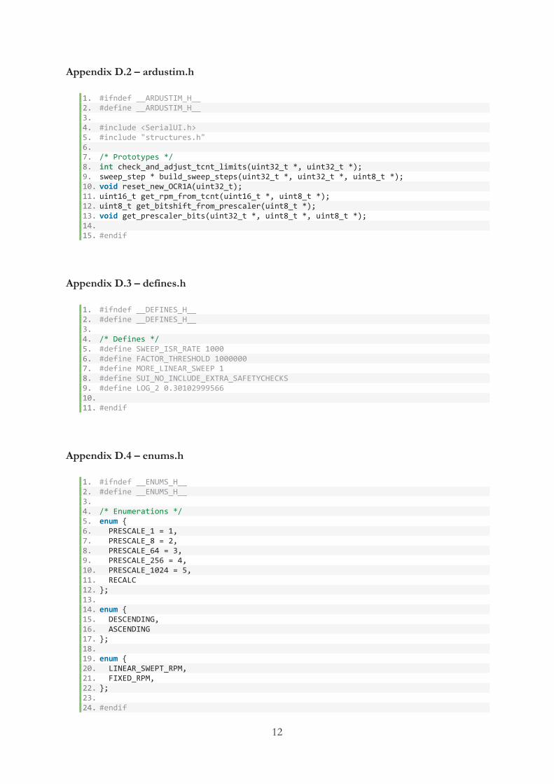
Timer1 is one of three hardware timers available on the chip. It is a 16 bit hardware timer controlled by the Timer1 library that was developed to quickly and easily set the PWM period or frequency of a timer. As previously mentioned, the clock frequency is defined through a prescaler [36]. The prescaler reduces the clock frequency by integer division as it divides the clock frequency by a value. Timer1 of the ArduinoTM Uno board has a clock speed of 16 MHz which is defined by setting the prescaler to either 1, 8, 64, 256 or 1024, see Table 3.3.3.1 [36].
Table 3.3.3.1: Clock frequency defined by prescaler value. Prescale Time per counter tick Max Period
1 0.0625 μs 8.192 ms 8 0.5 μs 65.536 ms 64 4 μs 524.288 ms 256 16 μs 2097.152 ms 1024 64 μs 8388.608 ms
3.3.4. Potentiometer and LCD As previously mentioned, a potentiometer is used to control the RPM in standalone mode. It is connected to analog pin 0 (A0) of the ArduinoTM board. Based on the voltage level that is controlled by the resistance value of the potentiometer, an analog value between 0-5 V is converted to a digital value between 0-1023 and read into the ArduinoTM board. In order to determine the correct RPM, this value is multiplied by 4 to be able to get resolutions up to 4096 RPM. However, a limit has been added at 3600 RPM since higher revolutions are not needed. The analog value is sent into a function that calculates an appropriate prescaler and defines the clock speed, which decides how often the pattern array should be read. With other words, it defines the time period of the signal.
Furthermore, the analog value is printed on the LCD to show the current RPM. To react quickly to changes and without blinking, the LCD is being updated every 100 ms. This part is being handled by the “loop()”-function, which only controls the LCD as well as the Serial UI. Since both the LCD and the Serial UI are being controlled by the “loop()”-function, only one of them can run at the same time. As soon as the program Druid4Arduino is opened, the program will focus on the Serial UI and the LCD as well as the potentiometers will be deactivated. When Druid4Arduino is closed, the components will be activated once again.

15
3.3.5. Seriul UI To be able to build the Serial UI for Druid4Arduino, the library “SerialUI.h” is needed. It is useful when menus, sub-menus or command executions are requested. The Serial UI is being controlled by the “loop()”-function. However, the actual code is presented in a sub-file called “serialmenu.h”.
The menus, texts and command executions that are shown in Druid4Arduino are created through several callbacks. A callback is a function used by the SerialUI library when a message arrives. The message handling code is placed in a function and the library is told to call it back when it receives the corresponding message [37], see Figure 3.3.5.1.
Figure 3.3.5.1: Main program calling a callback function [38].
When opening Druid4Arduino, the layout is comprised of a menu with several buttons, see Serial UI in Results.
3.4. Measurements Major parts of the signal generation are based on tests and measurements. By documents obtained from Volvo, attempts have been made to generate signals similar to the ones being generated from sensors in real engines, see Figure 3.4.1 from Appendix C. Although the signals are sinusoidal, it has not been necessary to generate this type of signals. The importance has been to create a signal with a quick zero-crossing between the maximum and minimum amplitude. Since the ECM converts the sinusoidal signal to a digital signal, this has been done with a digital signal directly.
Figure 3.4.1: Generated signals from obtained documents.

16
The signals have been generated through ArduinoTM and the output pins have been carefully examined in an oscilloscope of type Tektronix TDS3014. Since Ardu-Stim transmits the crank signal on pin 8 and the cam signal on pin 9, measurements were performed in order to see that the intended signals were received, see Measurement 1 in Results.
After this was verified, the creation of new wheel patterns began. To be able to transmit the signals on two pins each, two more pins needed to be initialized as output pins. The decision was to transmit the crank signal on pins 8-9 and the cam signal on pins 10-11. As SIMetrix predicted, resistances were needed in order to create the adder that merges the signals. Measurement 2 in Results shows the result of the measured signal with two sources.
When the correct wheel patterns had been created, the simulated circuit was built and the electronic hardware was tested in reality. After tests and verifications, some small modifications were made compared to the simulated circuit in SIMetrix. Since the ECM affects the circuit when it connects to the transformer, a buffer was connected to the operational amplifier as a feedback to increase the power to the transformer, see Figure 2.5.5.1. Test and verification in Results shows the final results.
3.5. Product structure The product is made of a plastic box with a metal lid. Inside the box is the location of the ArduinoTM Uno board as well as the electronic hardware that processes the generated signals, see Figure 3.5.1.
Figure 3.5.1: The inside of the box.

17
The Speed Sensor Simulator Box can be used in two modes; it can either run standalone or run by computer. Two potentiometers and a LCD is attached to the metal lid for standalone mode, see Figure 3.5.2. When in standalone mode, the LCD shows the generated speed in RPM while one potentiometer controls the speed and the other potentiometer controls the backlight of the LCD. The maximum RPM is 3600 and the potentiometer that controls the RPM increases with a resolution of 4 RPM at a time. However, when the unit runs by computer the RPM can be chosen with a resolution of 1 RPM.
Figure 3.5.2: The LCD and the potentiometers.
By connecting the unit to a computer via a USB-A cable, access to connect with Druid4Arduino is given. By opening the program, the LCD and the potentiometers that are used at standalone mode will be deactivated.
The benefit of running the unit by Druid4Arduino is the increased number of features. In addition to adjusting the speed, the user can also select different wheel patterns where the cam signal is displaced in relation to the crank signal. By closing Druid4Arduino, the LCD and the potentiometers will be activated once again.
Even though the unit is energized by the computer through the USB-A cable, supply voltage and ground needs to be connected to the box to power the electronic hardware. As the DC/DC-converter can receive voltages within the range of 9-36 V, this is a requirement for acceptable supply voltage. Outputs are also available for the ECM which receives and processes the generated cam- and crank signals, see Figure 3.5.3.
Figure 3.5.3: In- and outputs of the unit.

18
4. Alternative solutions The project can be done in several ways. The mentor at Volvo had two suggestions of solutions, where:
The first alternative was to use a pure microprocessor solution that together with an appropriate constructed circuit board generates and processes the cam and crank signals. A suggestion of microprocessor was ArduinoTM, since it is user-friendly and it is quite easy to define states for input and output pins.
The second alternative was to use a memory with a parallel output that clocks out the content with a controllable PLL to a DAC. In this way, the timing of single or combined signals can be controlled with great precision.
The project was performed with the microprocessor solution, which turned out to be working great. The signal generation could probably be programmed in several ways, however, the solution that Ardu-Stim used was well thought out and easy to understand.
Furthermore, the selection of electronic hardware could have been done differently. Instead of galvanic isolating the circuit with a transformer, another solution could have been to use an optocoupler. Except that the optocoupler galvanic isolates the circuits, this device also prevents electrical disorders from spreading through electrical systems [39].
However, since the transformer was tested and turned out to process the signals well, this component was chosen.

19
5. Results
5.1. Simulations results
5.1.1. Simulation 1 The following result refers to Figure 3.2.1 where a circuit with one source has been simulated, see Figure 5.1.1.1.
Figure 5.1.1.1: Simulation result from a circuit with one source.
5.1.2. Simulation 2 The following result refers to Figure 3.2.3 where a circuit with two sources has been simulated. The result is divided into three images where the first represents source 1 (Figure 5.1.2.1), the second represents source 2 (Figure 5.1.2.2) and the third represents the merged signal from the two sources (Figure 5.1.2.3).
Figure 5.1.2.1: Simulation result from source 1.

20
Figure 5.1.2.2: Simulation result from source 2.
Figure 5.1.2.3: Simulation result from the merged sources.
5.2. Software results
5.2.1. Calculations In order to get signal synchronization and correct displacements between the cam- and crank signals, some calculations had to be made. To determine the size of the wheel pattern array, the distance between each gear tooth was calculated according to formula (1).
This means that a gear tooth occurs every 6°. However, to be able to calculate the size of the wheel pattern array, the amount of edges per gear tooth needed to be calculated. Since the largest accuracy of a displacement is ¼°, it needs the most edges to be described. This was done through formula (2).

21
By this result, it means that it takes 24 edges in the wheel pattern array to create a 6° gear tooth that has the possibility to be displaced ¼°. Since one crank revolution consists of 60 gear teeth and two crank revolutions are required per cam revolution, a total number of 120 gear teeth are needed in the wheel pattern array. This gives the following size of the array, see formula (3):
To create patterns with smaller accuracy, fewer edges are needed. However, since the calculated pattern size of 2880 edges can create all the wanted patterns of ½°, 1° and 2°, the same size were used for all displacements.
As mentioned in section 3.3.2, the “RPM” scaler” that helps deciding the prescaler of a timer needed to be calculated. This was done through formula (4):
The wheel array ratio is predetermined by the creator of Ardu-Stim. In wheel patterns where only one crank revolution occurs, this value is set to 120. In wheel patterns where two crank revolutions occur (typically patterns with a cam signal); this value is set to 240.
5.2.2. Construction of wheel patterns As calculated in section 5.2.1, each wheel pattern is defined through 2880 edges where 24 edges correspond to one gear tooth. Table 3.3.2.2 shows the different choices of values that are available for each edge. Since some values gives the same output signals, as well as every alternative not being needed, the following values have been used in the created wheel patterns:
0 – When both signals are low. 1 – When crank signal idles and cam signal is low. 4 – When crank signal is low and cam signal idles. 5 – When both signals idle. 7 – When crank signal is high and cam signal idles. 12 – When crank signal is low and cam signal is high. 13 – When crank signal idles and cam signal is high. 15 – When both signals are high.
The displacements are made with consideration to the synchronized signal, which has a cam displacement of ½°. Since each value in the array corresponds to ¼°, a displacement of ½° corresponds to two values. Table 5.2.2.1 shows a number of created gear teeth.

22
Table 5.2.2.1: Created gear teeth. Type of gear teeth Array description
Crank teeth used for all displacements 7,7,7,7,7,7,4,4,4,4,4,4,5,5,5,5,5,5,5,5,5,5,5,5 Cam teeth used for 0° displacement (sync) 5,5,13,13,13,13,13,13,1,1,1,1,1,1,5,5,5,5,5,5,5,5,5,5
Cam teeth used for ½° displacement 5,5,5,13,13,13,13,13,13,1,1,1,1,1,1,5,5,5,5,5,5,5,5,5 Cam teeth used for ¼° displacement 5,5,5,5,13,13,13,13,13,13,1,1,1,1,1,1,5,5,5,5,5,5,5,5 Cam teeth used for 1° displacement 5,5,5,5,5,5,13,13,13,13,13,13,1,1,1,1,1,1,5,5,5,5,5,5 Cam teeth used for 2° displacement 5,5,5,5,5,5,5,5,5,5,13,13,13,13,13,13,1,1,1,1,1,1,5,5
Since the cam teeth only occur during missing crank, it does not affect the crank teeth array description. Therefore, the same crank teeth array description is used in every wheel pattern. However, the cam signal varies from pattern to pattern. As seen in Table 5.2.2.1, the cam teeth array descriptions have displacements in relationship to each other, where every edge corresponds to a displacement of ¼°.
5.2.3. Serial UI This section presents the appearance of the Serial UI in Druid4Arduino, see Figure 5.2.3.1. The following information applies to each button:
Information – Gives the user information about the product as well as the currently selected wheel pattern.
Set RPM – A command execution to set the wanted RPM. If the selected RPM is not within the range of 10-3600 RPM, an error message occurs.
Sync – Synchronizes the cam and crank signals. However, this is a cam displacement of ½° and other displacements are done with consideration to this.
¼ degree – Displaces the cam signal ¼° in relation to the crank signal. ½ degree – Displaces the cam signal ½° in relation to the crank signal. 1 degree – Displaces the cam signal 1° in relation to the crank signal. 2 degrees – Displaces the cam signal 2° in relation to the crank signal.
Figure 5.2.3.1: Druid4Arduino layout.

23
5.3. Measurement results
5.3.1. Measurement 1 The following result refers to the measurements made on the original Ardu-Stim program where the cam- and crank signals were transmitted on one pin each. The cam- and crank signals have the same appearance; however, Figure 5.3.1.1 only shows the crank signal.
Figure 5.3.1.1: The crank signal transmitted on one pin.
5.3.2. Measurements 2 The following result refers to the measurements made on the modified Ardu-Stim program where the cam- and crank signals were transmitted on two pins each. The cam- and crank signals have the same appearance; however, Figure 5.3.2.1 only shows the crank signal.
Figure 5.3.2.1: The crank signal transmitted on two pins.
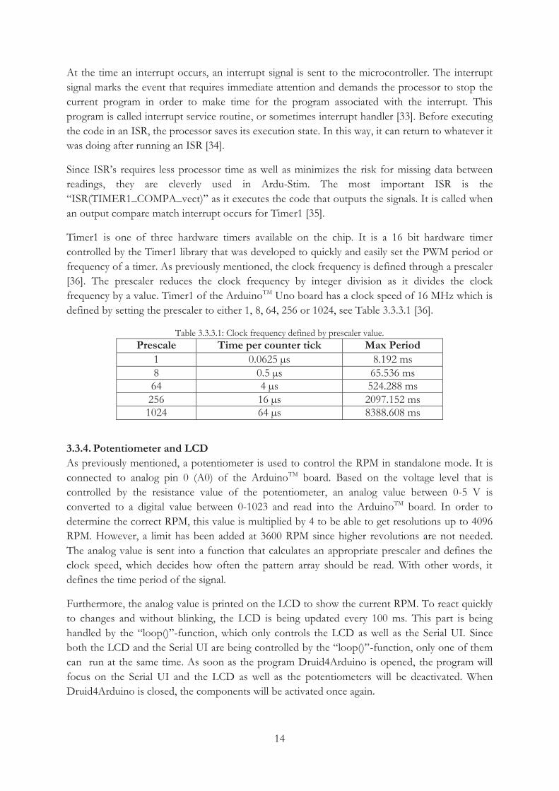
5.4. Test and verification When the correct wheel pattern had been created, the cam- and crank signals were connected to the electronic hardware. After connecting the ECM to the circuit, measurements were made to test and verify that the unit worked as intended. The result was a product that worked in standalone mode as well as controlled by a computer. In both methods, the signals appeared as they should, see Figures 5.4.1-5.4.5.
At last, the Speed Sensor Simulator Box was connected to an ECM controlled by a computer and it was confirmed that the generated RPM was received.
24
Figure 5.4.1: The cam- (blue) and crank (yellow) signals in sync, which has a displacement of ½°.
Figure 5.4.2: The cam- (blue) and crank (yellow) signals with a displacement of ¼°.
Figure 5.4.3: The cam- (blue) and crank (yellow) signals with a displacement of ½°.
Figure 5.4.4: The cam- (blue) and crank (yellow) signals with a displacement of 1°.

25
Figure 5.4.5: The cam- (blue) and crank (yellow) signals with a displacement of 2°.

26
6. Discussion and conclusion The purpose of this thesis work was to design a Speed Sensor Simulator Box that can be used at tests and measurements of ECM’s. After 10 weeks of work, the result is a functional product that meets the given specifications. We have succeeded to create a unit which contains software as well as electronic hardware that together generate and process cam and crank signals.
The problems that were formulated before the start of the thesis work have been managed to be covered in a good way. The signal generation is performed through ArduinoTM and the selected components of the constructed circuit board are based on tests and measurements. To be able to determine the appropriate components by tests, Volvo has given us free choice of purchasing. This has given us a greater selection and facilitated the work.
Before the appropriate circuit was determined, different solutions were tested. As previously mentioned, the buffer was not a part of the original circuit. However, this was needed to provide an increased power to the transformer. Another test was to use a low-pass filter between the ArduinoTM outputs and the operational amplifier, in order to get a sinusoidal signal. The low-pass filter worked as intended, but we quickly understood that this would not work all the time since the adjustment of RPM generates different frequencies. This would result in a filter not working at certain speeds. Our mentor at Volvo also explained that the importance is not to have a sinusoidal signal, but to have a signal with a quick zero-crossing between the maximum and minimum amplitude. Therefore, the filter could be neglected.
The software is based on the open-source program code called Ardu-Stim. Before the beginning of this project, none of us had any particular knowledge of ArduinoTM. The code needed to be carefully reviewed in order to be able to modify the necessary parts. This was facilitated by previous programming skills as well as all the information available online.
One thing that was quite tricky was to get a functional display. For some reason, the original pin configuration for the LCD did not work. After a bit of research we found out that one of the pins that was used by the LCD also were used by one of the ArduinoTM timers. By initializing available pins for the LCD, this was solved.
The product itself is a clean box which is easy to use. Since the project had a time limit of 10 weeks, the product design could not be too advanced. However, it could have been done with some improvements. A bigger display or perhaps a touch screen is two examples. Another upgrade that can be developed in the future is the possibility of switching patterns with a potentiometer. This could possibly be achieved if more time were given.

27
Bibliography
[1] Volvo Trucks Sweden, "Mer än 80 år i transportbranschen," Volvo Trucks, 2015. [Online]. Available: http://www.volvotrucks.com/trucks/sweden-market/sv-se/aboutus/Pages/About%20us%20-%20Opening%20page.aspx. [Accessed 05 05 2015].
[2] Volvo Group Sverige, "Volvo Group Trucks Technology," Volvo Group, 2014. [Online]. Available: http://www.volvogroup.com/group/sweden/sv-se/Volvo%20Group/our%20companies/GTtechnology/Pages/GTT.aspx. [Accessed 05 05 2015].
[3] AA1Car, "Crankshaft & Camshaft Position Sensors," AA1Car, [Online]. Available: http://www.aa1car.com/library/crank_sensors.htm. [Accessed 05 05 2015].
[4] Wikipedia, "Kamaxel," Wikipedia, 05 11 2014. [Online]. Available: http://sv.wikipedia.org/wiki/Kamaxel. [Accessed 12 05 2015].
[5] HowACarWorks, "Engine with overhead camshaft," HowACarWorks, [Online]. Available: http://www.howacarworks.com/illustrations/engine-with-overhead-camshaft. [Accessed 12 05 2015].
[6] K. Nice, "How Camshafts Work," HowStuffWorks, [Online]. Available: http://auto.howstuffworks.com/camshaft.htm. [Accessed 12 05 2015].
[7] C. Woodford, "Crank and cams," ExplainThatStuff, 10 08 2014. [Online]. Available: http://www.explainthatstuff.com/cranks-and-cams.html. [Accessed 10 05 2015].
[8] N. Hall, "Engine Power Train," NASA, 05 05 2015. [Online]. Available: http://www.grc.nasa.gov/WWW/K-12/airplane/powert.html. [Accessed 11 05 2015].
[9] Wikipedia, "Crankshaft," Wikipedia, 15 05 2015. [Online]. Available: http://en.wikipedia.org/wiki/Crankshaft. [Accessed 17 05 2015].
[10] Jones & Bartlett Learning, "Crankshaft/Camshaft Relationship," Jones & Bartlett Learning, 2013. [Online]. Available: http://lincolntrial.integr8cms.net/index.php/76-disc-brakes/section-10/comien/2602-crankshaft-camshaft-relationship. [Accessed 17 05 2015].
[11] Full Function Engineering, "Hall vs. Variable Reluctance Sensors," Full Function Engineering, 2012. [Online]. Available: http://fullfunctioneng.com/info/Hall%20vs%20VR.pdf. [Accessed 11 05 2015].
[12] J. A. Callen, "Variable Reluctance Speed Sensor (VR)," Instronics, [Online]. Available: http://www.instronics.com/sensoronix_variable_reluctance_speed_sensor.html. [Accessed 11 05 2015].

28
[13] SIMetrix Technologies, "Circuit simulation without compromise," SIMetrix Technologies, 2015. [Online]. Available: http://www.simetrix.co.uk/. [Accessed 13 05 2015].
[14] Wikipedia, "Arduino," Wikipedia, 22 05 2015. [Online]. Available: http://en.wikipedia.org/wiki/Arduino . [Accessed 27 05 2015].
[15] Arduino, "What is Arduino?," Arduino, 2015. [Online]. Available: http://www.arduino.cc/en/guide/introduction. [Accessed 27 05 2015].
[16] Wiring, "What will YOU do with the W?," Wiring, 2015. [Online]. Available: http://wiring.org.co/. [Accessed 27 05 2015].
[17] Arduino, "Arduino Uno," Arduino, 2015. [Online]. Available: http://www.arduino.cc/en/Main/ArduinoBoardUno. [Accessed 27 05 2015].
[18] FlyingCarsAndStuff, "Druid4Arduino," FlyingCarsAndStuff, [Online]. Available: http://flyingcarsandstuff.com/projects/druid4arduino/. [Accessed 26 05 2015].
[19] Elfa, "3540/3541 - Precision Potentiometer," Bourns, [Online]. Available: https://www1.elfa.se/data1/wwwroot/assets/datasheets/3540-41-series_eng_tds.pdf. [Accessed 03 06 2015].
[20] Arduino, "Reading a Potentiometer (analog input)," Arduino, 2015. [Online]. Available: http://www.arduino.cc/en/Tutorial/Potentiometer. [Accessed 28 05 2015].
[21] Kjell & Company, "ATM1602-FL-YBW," Kjell & Company, [Online]. Available: http://www.kjell.com/sortiment/el/elektronik/optokomponenter/led-lcd-displayer/lcd-display-p90215. [Accessed 03 06 2015].
[22] Elfa, "THD-transformator;600 Ω - 600 Ω ct, 6235.0," Elfa, 2015. [Online]. Available: https://www.elfa.se/elfa3~se_sv/elfa/init.do?item=56-661-02&toc=0. [Accessed 03 06 2015].
[23] Wikipedia, "Transformer," Wikipedia, 28 05 2015. [Online]. Available: http://en.wikipedia.org/wiki/Transformer. [Accessed 28 05 2015].
[24] Wikipedia, "DC-to-DC converter," Wikipedia, 01 04 2015. [Online]. Available: http://en.wikipedia.org/wiki/DC-to-DC_converter. [Accessed 28 05 2015].
[25] Elfa, "DC/DC Converters," Traco Power, [Online]. Available: https://www1.elfa.se/data1/wwwroot/assets/datasheets/ten5wi_eng_tds.pdf. [Accessed 03 06 2015].
[26] Farnell, "Operational Amplifiers," Texas Instruments, 2015. [Online]. Available: http://www.farnell.com/datasheets/1905671.pdf. [Accessed 03 06 2015].
[27] Burr-Brown, "BUF634," Burr-Brown, 2014. [Online]. Available:

29
http://www.mouser.com/ds/2/405/buf634-484794.pdf. [Accessed 28 05 2015].
[28] O. S. H. Group, "Tutorial 01-Tutorial 12," TouTube, 11 2014. [Online]. Available: https://www.youtube.com/user/OSHJunkies/videos. [Accessed 24 03 2015].
[29] Arduino, "Examples," Arduino, 2015. [Online]. Available: http://www.arduino.cc/en/Tutorial/HomePage. [Accessed 28 05 2015].
[30] D. J. Andruczyk, "Arduino based crank/cam wheel simulator: ardu-stim," LibreEMS, 04 03 2014. [Online]. Available: http://blogs.libreems.org/arduino-wheel-simulator/. [Accessed 22 04 2015].
[31] GNU, "Licenses," GNU, 08 03 2015. [Online]. Available: http://www.gnu.org/licenses/. [Accessed 28 05 2015].
[32] Wikipedia, "Galvanic isolation," Wikipedia, 22 12 2014. [Online]. Available: http://en.wikipedia.org/wiki/Galvanic_isolation. [Accessed 29 05 2015].
[33] S. User, "Polling vs. Interrupt," Electronics-Base, 11 12 2011. [Online]. Available: http://www.electronics-base.com/useful-info/software-related/90-polling-vs-interrupt. [Accessed 31 05 2015].
[34] J. Dee, "Processor Interrupts with Arduino," Sparkfun, 24 01 2012. [Online]. Available: https://www.sparkfun.com/tutorials/326. [Accessed 31 05 2015].
[35] RobotFreak, "Arduino 101: Timers and Interrupts," Let'sMakeRobots, 07 08 2011. [Online]. Available: http://letsmakerobots.com/content/arduino-101-timers-and-interrupts. [Accessed 31 05 2015].
[36] Arduino, "Timer1," Arduino, 2015. [Online]. Available: http://playground.arduino.cc/Code/Timer1. [Accessed 31 05 2015].
[37] Arduino, "What is a callback?," Arduino, 2015. [Online]. Available: http://playground.arduino.cc/Main/MIDILibraryCallbacks. [Accessed 02 06 2015].
[38] D. Hünniger, "Callback-notitle," Wikipedia, 20 04 2006. [Online]. Available: http://en.wikipedia.org/wiki/Callback_%28computer_programming%29#/media/File:Callback-notitle.svg. [Accessed 02 06 2015].
[39] Wikipedia, "Optokopplare," Wikipedia, 30 01 2015. [Online]. Available: http://sv.wikipedia.org/wiki/Optokopplare. [Accessed 03 06 2015].

1
Appendices
Appendix A – Schematic
2
Appendix B – Specification from Volvo

3
Appendix C – Volvo MD13 with EGR

4

5
Appendix D – Modified Ardu-Stim program code
Appendix D.1 – ardustim.ino
1. #include "defines.h" 2. #include "ardustim.h" 3. #include "enums.h" 4. #include "serialmenu.h" 5. #include "wheel_defs.h" 6. #include <avr/pgmspace.h> 7. #include <SerialUI.h> 8. #include <LiquidCrystal.h> 9. LiquidCrystal lcd(7, 6, 5, 4, 3, 2); 10. 11. /* Sensistive stuff used in ISR's */ 12. volatile uint8_t fraction = 0; 13. volatile uint8_t selected_wheel = VOLVO_MD13_WITH_EGR_CAM_SYNCED; 14. volatile uint16_t analog0; // Coarse RPM 15. volatile uint16_t potRPM; 16. volatile uint32_t oc_remainder = 0; 17. 18. // Setting RPM to any value over 0 will enable sweeping by default 19. /* Stuff for handling prescaler changes (small tooth wheels are low RPM) */ 20. volatile uint8_t analog_port = 0; 21. volatile bool adc_read_complete = false; 22. volatile bool reset_prescaler = false; 23. volatile bool normal = true; 24. volatile bool sweep_reset_prescaler = true; // Force sweep to reset prescaler value
25. volatile bool sweep_lock = false; 26. volatile uint8_t output_invert_mask = 0x00; // Don't invert anything 27. volatile uint8_t sweep_direction = ASCENDING; 28. volatile byte total_sweep_stages = 0; 29. volatile int8_t sweep_stage = 0; 30. volatile uint8_t prescaler_bits = 0; 31. volatile uint8_t last_prescaler_bits = 0; 32. volatile uint8_t mode = FIXED_RPM; 33. volatile uint16_t new_OCR1A = 5000; // Sane default 34. volatile uint16_t edge_counter = 0; 35. 36. /* Less sensitive globals */ 37. uint8_t bitshift = 0; 38. uint16_t sweep_low_rpm = 0; 39. uint16_t sweep_high_rpm = 0; 40. uint16_t sweep_rate = 0; 41. 42. SUI::SerialUI mySUI = SUI::SerialUI(greeting); 43. 44. sweep_step *SweepSteps; // Global pointer for the sweep steps 45. 46. wheels Wheels[MAX_WHEELS] = { 47. /* Pointer to friendly name string, pointer to edge array, RPM Scaler, Number of e
dges in the array */ 48. { volvo_md13_with_egr_cam_synced_friendly_name, volvo_md13_with_egr_cam_synced, 12
, 2880 }, 49. { volvo_md13_with_egr_cam_displaced_quarter_friendly_name, volvo_md13_with_egr_cam
_displaced_quarter, 12, 2880 }, 50. { volvo_md13_with_egr_cam_displaced_half_friendly_name, volvo_md13_with_egr_cam_di
splaced_half, 12, 2880 }, 51. { volvo_md13_with_egr_cam_displaced_one_friendly_name, volvo_md13_with_egr_cam_dis
placed_one, 12, 2880 }, 52. { volvo_md13_with_egr_cam_displaced_two_friendly_name, volvo_md13_with_egr_cam_dis
placed_two, 12, 2880 }, 53. };

6
54. 55. /* Initialization */ 56. void setup() { 57. lcd.begin(16, 2); 58. 59. serial_setup(); 60. 61. cli(); // Stop interrupts 62. 63. /* Configuring timer1 */ 64. // Set timer1 to generate pulses 65. TCCR1A = 0; 66. TCCR1B = 0; 67. TCNT1 = 0; 68. 69. // Set compare register to sane default 70. OCR1A = 1000; 71. 72. // Turn on CTC mode 73. TCCR1B |= (1 << WGM12); // Normal mode (not PWM) 74. // Set prescaler to 1 75. TCCR1B |= (1 << CS10); 76. // Enable output compare interrupt for timer1 (16 bit) 77. TIMSK1 |= (1 << OCIE1A); 78. 79. /* Configuring timer2 */ 80. // Set timer2 to run sweeper routine 81. TCCR2A = 0; 82. TCCR2B = 0; 83. TCNT2 = 0; 84. 85. // Set compare register to sane default 86. OCR2A = 249; // With prescale of x64 gives 1 ms tick 87. 88. // Turn on CTC mode 89. TCCR2A |= (1 << WGM21); // Normal mode (not PWM) 90. // Set prescaler to x64 91. TCCR2B |= (1 << CS22); 92. // Enable output compare interrupt for timer2 93. TIMSK2 |= (1 << OCIE2A); 94. 95. 96. /* Configuring ADC */ 97. // Clear ADLAR in ADMUX (0x7C) to right-adjust the result 98. // ADCL will contain lower 8 bits, ADCH upper 2 bits 99. ADMUX &= B11011111; 100. 101. // Set REFS1..0 in ADMUX (0x7C) to change reference voltage to the proper so
urce (01) 102. ADMUX |= B01000000; 103. 104. // Clear MUX3..0 in ADMUX (0x7C) in preparation for setting the analog input
105. ADMUX &= B11110000; 106. 107. // Set ADEN in ADCSRA (0x7A) to enable the ADC 108. ADCSRA |= B10000000; 109. 110. // Set ADATE in ADCSRA (0x7A) to enable auto-triggering 111. ADCSRA |= B00100000; 112. 113. // Clear ADTS2..0 in ADCSRB (0x7B) to set trigger mode to free running 114. // This means that as soon as an ADC has finished, the next will be immediat
ely started 115. ADCSRB &= B11111000; 116.

7
117. // Set the Prescaler to 128 (16000KHz/128 = 125KHz) 118. // Above 200KHz 10-bit results are not reliable 119. ADCSRA |= B00000111; 120. 121. // Set ADIE in ADCSRA (0x7A) to enable the ADC interrupt 122. // Without this, the internal interrupt will not trigger 123. ADCSRA |= B00001000; 124. 125. pinMode(8, OUTPUT); // Crank output 1 126. pinMode(9, OUTPUT); // Crank output 2 127. pinMode(10, OUTPUT); // Cam output 1 128. pinMode(11, OUTPUT); // Cam output 2 129. 130. sei(); // Enable interrupts 131. 132. // Set ADSC in ADCSRA (0x7A) to start the ADC conversion 133. ADCSRA |=B01000000; 134. } // End setup 135. 136. 137. /* ADC ISR for alternating between ADC pins 0 and 1 */ 138. // Reads ADC ports 0 and 1 alternately 139. // Port 0 is coarse RPM with about 64 RPM resolution 140. // Port 1 is fine RPM and is used to calculate a more precise RPM signal 141. ISR(ADC_vect){ 142. if (analog_port == 0) 143. { 144. analog0 = ADCL | (ADCH << 8); 145. adc_read_complete = true; 146. } 147. } 148. 149. 150. /* This is the "low speed" 1000x/second sweeper ISR who's sole 151. * purpose is to reset the output compare value for timer0 to 152. * change the output RPM. In cases where the RPM change per ISR 153. * is LESS than one LSB of the counter a set of modulus variabels 154. * are used to handle fractional values. */ 155. ISR(TIMER2_COMPA_vect) { 156. if ( mode != LINEAR_SWEPT_RPM) 157. { 158. return; 159. } 160. if (sweep_lock) // Semaphore to protect around changes/critical sections 161. { 162. return; 163. } 164. sweep_lock = true; 165. if (sweep_reset_prescaler) 166. { 167. sweep_reset_prescaler = false; 168. reset_prescaler = true; 169. prescaler_bits = SweepSteps[sweep_stage].prescaler_bits; 170. last_prescaler_bits = prescaler_bits; 171. } 172. /* Sweep code */ 173. if (sweep_direction == ASCENDING) // Ascending 174. { 175. oc_remainder += SweepSteps[sweep_stage].remainder_per_isr; 176. // If the total is over the threshold the TCNT factor is incremented for e
ach multiple it is over by 177. while (oc_remainder > FACTOR_THRESHOLD) 178. { 179. fraction++; 180. oc_remainder -= FACTOR_THRESHOLD; 181. }

8
182. if (new_OCR1A > SweepSteps[sweep_stage].ending_ocr) 183. { 184. new_OCR1A -= (SweepSteps[sweep_stage].tcnt_per_isr + fraction); 185. fraction = 0; 186. } 187. else // End of the stage, find out where we are 188. { 189. sweep_stage++; 190. oc_remainder = 0; 191. if (sweep_stage < total_sweep_stages) 192. { 193. new_OCR1A = SweepSteps[sweep_stage].beginning_ocr; 194. if (SweepSteps[sweep_stage].prescaler_bits != last_prescaler_bits) 195. sweep_reset_prescaler = true; 196. } 197. else // End of line, time to reverse direction 198. { 199. sweep_stage--; // Bring back within limits 200. sweep_direction = DESCENDING; 201. new_OCR1A = SweepSteps[sweep_stage].ending_ocr; 202. if (SweepSteps[sweep_stage].prescaler_bits != last_prescaler_bits) 203. sweep_reset_prescaler = true; 204. } 205. } 206. } 207. else // Descending 208. { 209. oc_remainder += SweepSteps[sweep_stage].remainder_per_isr; 210. while (oc_remainder > FACTOR_THRESHOLD) 211. { 212. fraction++; 213. oc_remainder -= FACTOR_THRESHOLD; 214. } 215. if (new_OCR1A < SweepSteps[sweep_stage].beginning_ocr) 216. { 217. new_OCR1A += (SweepSteps[sweep_stage].tcnt_per_isr + fraction); 218. fraction = 0; 219. } 220. else // End of stage 221. { 222. sweep_stage--; 223. oc_remainder = 0; 224. if (sweep_stage >= 0) 225. { 226. new_OCR1A = SweepSteps[sweep_stage].ending_ocr; 227. if (SweepSteps[sweep_stage].prescaler_bits != last_prescaler_bits) 228. sweep_reset_prescaler = true; 229. } 230. else // End of line 231. { 232. sweep_stage++; // Bring back within limits 233. sweep_direction = ASCENDING; 234. new_OCR1A = SweepSteps[sweep_stage].beginning_ocr; 235. if (SweepSteps[sweep_stage].prescaler_bits != last_prescaler_bits) 236. sweep_reset_prescaler = true; 237. } 238. } 239. } 240. sweep_lock = false; 241. } 242. 243. /* Pumps the pattern out of flash to the port */ 244. // The rate at which this runs is dependent on what OCR1A is set to 245. // The sweeper in timer2 alters this on the fly to allow changing of RPM in a
very nice way 246. ISR(TIMER1_COMPA_vect) {

9
247. // Walks the array and wraps when the limit is hit 248. PORTB = output_invert_mask ^ pgm_read_byte(&Wheels[selected_wheel].edge_stat
es_ptr[edge_counter]); // Write it to the port 249. 250. // Normal direction overflow handling 251. if (normal) 252. { 253. edge_counter++; 254. if (edge_counter == Wheels[selected_wheel].wheel_max_edges) { 255. edge_counter = 0; 256. } 257. } 258. else 259. { 260. if (edge_counter == 0) 261. edge_counter = Wheels[selected_wheel].wheel_max_edges; 262. edge_counter--; 263. } 264. 265. // Reset prescaler only if flag is set 266. if (reset_prescaler) 267. { 268. TCCR1B &= ~((1 << CS10) | (1 << CS11) | (1 << CS12)); // Clear CS10, CS11
and CS12 269. TCCR1B |= prescaler_bits; 270. reset_prescaler = false; 271. } 272. // Reset next compare value for RPM changes 273. OCR1A = new_OCR1A; // Apply new "RPM" from timer2 ISR, i.e. speed up/down t
he virtual "wheel" 274. } 275. 276. void loop() { 277. /* Just handles the Serial UI and the LCD */ 278. // Eerything else is in interrupt handlers or callbacks from SerialUI. 279. lcd.setCursor(0, 0); 280. lcd.print("RPM:"); 281. lcd.setCursor(5, 0); 282. lcd.print(potRPM * 4); 283. delay(100); 284. lcd.clear(); 285. 286. if (analog0 >= 900) 287. potRPM = 900; 288. else 289. potRPM = analog0; 290. 291. if (mySUI.checkForUserOnce()) 292. { 293. // Someone connected! 294. mySUI.enter(); 295. while (mySUI.userPresent()) 296. { 297. mySUI.handleRequests(); 298. } 299. } 300. if (adc_read_complete == true) 301. { 302. reset_new_OCR1A(potRPM << 2); 303. adc_read_complete = false; 304. } 305. } 306. 307. 308. void reset_new_OCR1A(uint32_t new_rpm) 309. {

10
310. uint32_t tmp; 311. uint8_t bitshift; 312. uint8_t tmp_prescaler_bits; 313. tmp = (uint32_t)(8000000.0/(Wheels[selected_wheel].rpm_scaler * (float)(new_
rpm < 10 ? 10:new_rpm))); 314. get_prescaler_bits(&tmp,&tmp_prescaler_bits,&bitshift); 315. new_OCR1A = (uint16_t)(tmp >> bitshift); 316. prescaler_bits = tmp_prescaler_bits; 317. reset_prescaler = true; 318. } 319. 320. 321. uint8_t get_bitshift_from_prescaler(uint8_t *prescaler_bits) 322. { 323. switch (*prescaler_bits) 324. { 325. case PRESCALE_1024: 326. return 10; 327. case PRESCALE_256: 328. return 8; 329. case PRESCALE_64: 330. return 6; 331. case PRESCALE_8: 332. return 3; 333. case PRESCALE_1: 334. return 0; 335. } 336. return 0; 337. } 338. 339. 340. /* Gets RPM from the TCNT value */ 341. // Gets the RPM value based on the passed TCNT and prescaler 342. // \param tcnt pointer to output compare register value 343. // \param prescaler_bits pointer to prescaler bits enum 344. uint16_t get_rpm_from_tcnt(uint16_t *tcnt, uint8_t *prescaler_bits) 345. { 346. bitshift = get_bitshift_from_prescaler(prescaler_bits); 347. return (uint16_t)((float)(8000000 >> bitshift)/(Wheels[selected_wheel].rpm_s
caler*(*tcnt))); 348. } 349. 350. // Gets prescaler enum and bitshift based on OC value 351. void get_prescaler_bits(uint32_t *potential_oc_value, uint8_t *prescaler, uint
8_t *bitshift) 352. { 353. if (*potential_oc_value >= 16777216) 354. { 355. *prescaler = PRESCALE_1024; 356. *bitshift = 10; 357. } 358. else if (*potential_oc_value >= 4194304) 359. { 360. *prescaler = PRESCALE_256; 361. *bitshift = 8; 362. } 363. else if (*potential_oc_value >= 524288) 364. { 365. *prescaler = PRESCALE_64; 366. *bitshift = 6; 367. } 368. else if (*potential_oc_value >= 65536) 369. { 370. *prescaler = PRESCALE_8; 371. *bitshift = 3; 372. }

11
373. else 374. { 375. *prescaler = PRESCALE_1; 376. *bitshift = 0; 377. } 378. } 379. 380. // Builds the SweepSteps[] structure 381. /* For sweeping we cannot just pick the TCNT value at the beginning and ending
382. * and sweep linearly between them as it will result in a very slow RPM change
383. * at the low end and a very fast RPM change at the high end, due to the inver
se 384. * relationship between RPM and TCNT. So we compromise and break up the RPM 385. * range into octaves (doubles of RPM), and use a linear TCNT change between 386. * those two points. It is not perfect, but computationally easy. */ 387. 388. // \param low_rpm_tcnt pointer to low RPM OC value (not prescaled) 389. // \param high_rpm_tcnt pointer to high RPM OC value (not prescaled) 390. // \param total_stages pointer to tell the number of structs to allocate 391. // \returns pointer to array of structures for each sweep stage 392. sweep_step *build_sweep_steps(uint32_t *low_rpm_tcnt, uint32_t *high_rpm_tcnt,
uint8_t *total_stages) 393. { 394. sweep_step *steps; 395. uint8_t prescaler_bits; 396. uint8_t bitshift; 397. uint32_t tmp = *low_rpm_tcnt; 398. 399. steps = (sweep_step *)malloc(sizeof(sweep_step)*(*total_stages)); 400. 401. #ifdef MORE_LINEAR_SWEEP 402. for (uint8_t i = 0; i < (*total_stages); i+=2) 403. #else 404. for (uint8_t i = 0; i < (*total_stages); i++) 405. #endif 406. { 407. // The low RPM value will always have the highest TCNT value, so use that
to determine the prescaler value 408. get_prescaler_bits(&tmp, &steps[i].prescaler_bits, &bitshift); 409. 410. steps[i].beginning_ocr = (uint16_t)(tmp >> bitshift); 411. if ((tmp >> 1) < (*high_rpm_tcnt)) 412. steps[i].ending_ocr = (uint16_t)((*high_rpm_tcnt) >> bitshift); 413. else 414. steps[i].ending_ocr = (uint16_t)(tmp >> (bitshift + 1)); // Half the beg
in value 415. tmp = tmp >> 1; // Divide by 2 416. } 417. return steps; 418. }
12
Appendix D.2 – ardustim.h
1. #ifndef __ARDUSTIM_H__ 2. #define __ARDUSTIM_H__ 3. 4. #include <SerialUI.h> 5. #include "structures.h" 6. 7. /* Prototypes */ 8. int check_and_adjust_tcnt_limits(uint32_t *, uint32_t *); 9. sweep_step * build_sweep_steps(uint32_t *, uint32_t *, uint8_t *); 10. void reset_new_OCR1A(uint32_t); 11. uint16_t get_rpm_from_tcnt(uint16_t *, uint8_t *); 12. uint8_t get_bitshift_from_prescaler(uint8_t *); 13. void get_prescaler_bits(uint32_t *, uint8_t *, uint8_t *); 14. 15. #endif
Appendix D.3 – defines.h
1. #ifndef __DEFINES_H__ 2. #define __DEFINES_H__ 3. 4. /* Defines */ 5. #define SWEEP_ISR_RATE 1000 6. #define FACTOR_THRESHOLD 1000000 7. #define MORE_LINEAR_SWEEP 1 8. #define SUI_NO_INCLUDE_EXTRA_SAFETYCHECKS 9. #define LOG_2 0.30102999566 10. 11. #endif
Appendix D.4 – enums.h
1. #ifndef __ENUMS_H__ 2. #define __ENUMS_H__ 3. 4. /* Enumerations */ 5. enum { 6. PRESCALE_1 = 1, 7. PRESCALE_8 = 2, 8. PRESCALE_64 = 3, 9. PRESCALE_256 = 4, 10. PRESCALE_1024 = 5, 11. RECALC 12. }; 13. 14. enum { 15. DESCENDING, 16. ASCENDING 17. }; 18. 19. enum { 20. LINEAR_SWEPT_RPM, 21. FIXED_RPM, 22. }; 23. 24. #endif

13
Appendix D.5 – serialmenu.cpp
1. #include "defines.h" 2. #include "ardustim.h" 3. #include "enums.h" 4. #include "serialmenu.h" 5. #include "structures.h" 6. #include "wheel_defs.h" 7. #include <avr/pgmspace.h> 8. #include <math.h> 9. #include <util/delay.h> 10. #include <SerialUI.h> 11. #include <LiquidCrystal.h> 12. 13. /* File local variables */ 14. static uint16_t wanted_rpm = 0; 15. 16. /* External global variables */ 17. extern SUI::SerialUI mySUI; 18. extern sweep_step *SweepSteps; // Global pointer for the sweep steps 19. extern wheels Wheels[]; 20. extern uint8_t mode; 21. extern uint8_t total_sweep_stages; 22. extern uint16_t sweep_low_rpm; 23. extern uint16_t sweep_high_rpm; 24. extern uint16_t sweep_rate; 25. 26. /* External volatile variables (USED in ISR's) */ 27. extern volatile uint8_t selected_wheel; 28. extern volatile uint8_t sweep_direction; 29. extern volatile uint8_t sweep_stage; 30. extern volatile bool normal; 31. extern volatile bool sweep_lock; 32. extern volatile bool sweep_reset_prescaler; 33. extern volatile uint16_t edge_counter; 34. extern volatile uint16_t new_OCR1A; 35. extern volatile uint32_t oc_remainder; 36. 37. /* Initializes the serial port and sets up the menu */ 38. // Sets up the serial port and menu for the serial user interface 39. // Sets user input timeout to 20 seconds and overall interactivity timeout to 12, at
which point it will disconnect the user 40. void serial_setup() 41. { 42. mySUI.begin(9600); 43. mySUI.setTimeout(20000); 44. mySUI.setMaxIdleMs(15000); 45. SUI::Menu *mainMenu = mySUI.topLevelMenu(); 46. SUI::Menu *wheelMenu; 47. SUI::Menu *advMenu; 48. 49. /* Configuring meny */ 50. mainMenu->setName(top_menu_title); 51. mainMenu->addCommand(info_key,show_info_cb,info_help); 52. mainMenu->addCommand(rpm_key,set_rpm_cb,rpm_help); 53. mainMenu->addCommand(sync,synced_cb,synced_help); 54. mainMenu->addCommand(quarter_degree,quarter_degree_cb,quarter_degree_help); 55. mainMenu->addCommand(half_degree,half_degree_cb,half_degree_help); 56. mainMenu->addCommand(one_degree,one_degree_cb,one_degree_help); 57. mainMenu->addCommand(two_degrees,two_degrees_cb,two_degrees_help); 58. } 59. 60. /* Helper function to spit out amount of RAM remainig */ 61. // Figures out the amount of free RAM remaining and returns it to the caller 62. uint16_t freeRam () {

14
63. extern int __heap_start, *__brkval; 64. int v; 65. return (int) &v - (__brkval == 0 ? (int) &__heap_start : (int) __brkval); 66. } 67. 68. /* SerialUI Callbacks */ 69. 70. // Returns info about status, mode and free RAM 71. void show_info_cb() 72. { 73. mySUI.println_P(info_title1); 74. mySUI.println_P(info_title2); 75. mySUI.println_P(info_title3); 76. mySUI.println_P(space); 77. mySUI.println_P(info_title4); 78. mySUI.println_P(info_title5); 79. mySUI.println_P(info_title6); 80. mySUI.println_P(info_title7); 81. mySUI.println_P(info_title8); 82. mySUI.println_P(space); 83. mySUI.print_P(free_ram); 84. mySUI.print(freeRam()); 85. mySUI.println_P(bytes); 86. mySUI.print_P(current_pattern); 87. if (selected_wheel == 0) 88. mySUI.println_P(synced); 89. else if (selected_wheel == 1) 90. mySUI.println_P(quarter_degree); 91. else if (selected_wheel == 2) 92. mySUI.println_P(half_degree); 93. else if (selected_wheel == 3) 94. mySUI.println_P(one_degree); 95. else 96. mySUI.println_P(two_degrees); 97. if (mode == FIXED_RPM) { 98. mySUI.print_P(fixed_current_rpm); 99. mySUI.println(wanted_rpm); 100. } 101. } 102. 103. 104. // Displays newly selected wheel information 105. /* Resets the output compare register for the newly changed wheel, then 106. * resets edge_counter (wheel array index) to 0 and displays the new 107. * wheel information to the end user */ 108. void display_new_wheel() 109. { 110. mySUI.println_P(new_wheel_chosen); 111. mySUI.print_P(Wheels[selected_wheel].decoder_name); 112. mySUI.print_P(space_at_colon_space); 113. mySUI.print(wanted_rpm); 114. mySUI.print_P(space); 115. mySUI.println_P(RPM); 116. if (mode != LINEAR_SWEPT_RPM) 117. reset_new_OCR1A(wanted_rpm); 118. } 119. 120. 121. void synced_cb() 122. { 123. selected_wheel = 0; 124. display_new_wheel(); 125. } 126. 127. 128. void quarter_degree_cb()

15
129. { 130. selected_wheel = 1; 131. display_new_wheel(); 132. } 133. 134. 135. void half_degree_cb() 136. { 137. selected_wheel = 2; 138. display_new_wheel(); 139. } 140. 141. 142. void one_degree_cb() 143. { 144. selected_wheel = 3; 145. display_new_wheel(); 146. } 147. 148. 149. void two_degrees_cb() 150. { 151. selected_wheel = 4; 152. display_new_wheel(); 153. } 154. 155. 156. // Changes the RPM based on user input 157. /* Prompts user for new RPM, reads it, validates it is within range, sets lock
to 158. * prevent a race condition with the sweeper, free's memory of SweepSteps 159. * structure if allocated, sets the mode to fixed RPM, recalculates the new OC
R1A 160. * value based on the user specified RPM and sets it and then removes the lock
. */ 161. void set_rpm_cb() 162. { 163. mySUI.showEnterNumericDataPrompt(); 164. uint32_t newRPM = mySUI.parseULong(); 165. if (newRPM < 10) 166. { 167. mySUI.returnError("Invalid RPM, RPM too low (minimum RPM is 10)"); 168. return; 169. } 170. else if (newRPM > 3600) 171. { 172. mySUI.returnError("Invalid RPM, RPM too high (maximum RPM is 3600)"); 173. 174. return; 175. } 176. /* Spinlock */ 177. while (sweep_lock) 178. _delay_us(1); 179. sweep_lock = true; 180. if (SweepSteps) 181. free(SweepSteps); 182. mode = FIXED_RPM; 183. reset_new_OCR1A(newRPM); 184. wanted_rpm = newRPM; 185. 186. mySUI.print_P(new_rpm_chosen); 187. mySUI.println(wanted_rpm); 188. sweep_lock = false; 189. }

16
Appendix D.6 – serialmenu.h
1. #ifndef __SERIAL_MENU_H__ 2. #define __SERIAL_MENU_H__ 3. #include <SerialUI.h> 4. 5. /* Callbacks */ 6. void show_info_cb(); 7. void set_rpm_cb(); 8. void synced_cb(); 9. void quarter_degree_cb(); 10. void half_degree_cb(); 11. void one_degree_cb(); 12. void two_degrees_cb(); 13. 14. /* General functions */ 15. void serial_setup(); 16. void display_new_wheel(); 17. void compute_sweep_stages(uint16_t *, uint16_t *); 18. 19. SUI_DeclareString(greeting,"+++ Welcome to the ArduStim +++\r\nEnter ? for help"); 20. SUI_DeclareString(bytes, " bytes"); 21. SUI_DeclareString(top_menu_title,"ArduStim Main Menu"); 22. SUI_DeclareString(info_key, "Information"); 23. SUI_DeclareString(info_help, "Retrieve data and current settings"); 24. SUI_DeclareString(rpm_key, "Set RPM"); 25. SUI_DeclareString(rpm_help, "Choose wanted RPM"); 26. SUI_DeclareString(sync, "Sync"); 27. SUI_DeclareString(synced, "0 degrees (sync)"); 28. SUI_DeclareString(synced_help, "Sync cam signal"); 29. SUI_DeclareString(quarter_degree, "1/4 degree"); 30. SUI_DeclareString(quarter_degree_help, "Displace cam signal 1/4 degree"); 31. SUI_DeclareString(half_degree, "1/2 degree"); 32. SUI_DeclareString(half_degree_help, "Displace cam signal 1/2 degree"); 33. SUI_DeclareString(one_degree, "1 degree"); 34. SUI_DeclareString(one_degree_help, "Displace cam signal 1 degree"); 35. SUI_DeclareString(two_degrees, "2 degrees"); 36. SUI_DeclareString(two_degrees_help, "Displace cam signal 2 degrees"); 37. SUI_DeclareString(info_title1, "Welcome to a Speed Sensor Simulator, written by Toma
s Serti"); 38. SUI_DeclareString(info_title2, "and Emil Hermansson as a Bachelor Thesis. The progra
m is"); 39. SUI_DeclareString(info_title3, "based on ArduStim, written by David J. Andruczyk.");
40. SUI_DeclareString(info_title4, "All simulations mimic real signals being generated f
rom a"); 41. SUI_DeclareString(info_title5, "Volvo MD13 with EGR which uses 60-2-2-
2 crank teeth and"); 42. SUI_DeclareString(info_title6, "6+1 cam teeth, but with various displacements betwee
n them."); 43. SUI_DeclareString(info_title7, "The displacements are made with consideration to the
"); 44. SUI_DeclareString(info_title8, "synced signal, which has a displacement of 1/2 degre
es."); 45. SUI_DeclareString(free_ram, "Free RAM: "); 46. SUI_DeclareString(colon_space, ": "); 47. SUI_DeclareString(space, " "); 48. SUI_DeclareString(RPM, "RPM"); 49. SUI_DeclareString(space_at_colon_space, " at: "); 50. SUI_DeclareString(new_wheel_chosen, "New displacement chosen: "); 51. SUI_DeclareString(new_rpm_chosen, "New RPM chosen: "); 52. SUI_DeclareString(current_pattern, "Currently selected displacement: "); 53. SUI_DeclareString(fixed_current_rpm, "Current RPM: "); 54. #endif

17
Appendix D.7 – structures.h
1. #ifndef __STRUCTURES_H__ 2. #define __STRUCTURES_H__ 3. 4. /* Structures */ 5. typedef struct _sweep_step sweep_step; 6. struct _sweep_step { 7. uint16_t beginning_ocr; 8. uint16_t ending_ocr; 9. uint8_t prescaler_bits; 10. uint32_t remainder_per_isr; 11. uint16_t tcnt_per_isr; 12. }; 13. 14. /* Tie things wheel related into one nicer structure */ 15. typedef struct _wheels wheels; 16. struct _wheels { 17. const char *decoder_name PROGMEM; 18. const unsigned char *edge_states_ptr PROGMEM; 19. const float rpm_scaler; 20. const uint16_t wheel_max_edges; 21. }; 22. #endif
Appendix D.8 – wheel_defs.h
1. #ifndef __WHEEL_DEFS_H__ 2. #define __WHEEL_DEFS_H__ 3. 4. #include <avr/pgmspace.h> 5. 6. // Wheel patterns 7. /* Wheel patterns define the pin states and specific times. The ISR runs 8. * at a constant speed related to the requested RPM. The requested RPM is 9. * scaled based on the length of each wheel's array. The reference pattern is 10. * "Cam signal displaced 1/4 degree" which has 2880 "edges" and a RPM scaling 11. * factor of 12 (2280/240 = 12). 12. * 13. * There is an enumeration (below) that lists the defined wheel types, 14. * as well as an array listing the rpm_scaling factors with regards to 15. * each pattern. 16. * 17. * NOTE: There is more than one way to define a wheel pattern. You can 18. * use more edges to get to 1 degree accuracy but the side effect is that 19. * the maximum RPM is capped because of that. Max RPM for the current 20. * patterns that use 2880 edges are 5000 RPM. However, the RPM is in this 21. * case capped to 3600 RPM since faster speeds are not needed. */ 22. 23. // Wheel types 24. /* This enumerations is the INDEX into the Wheels[] array of structures 25. * defined in main file. That struct contains pointers to the following: 26. * -Wheel name in a user friendly string 27. * -Pointer to the wheel edge array used by the ISR 28. * -RPM scaling factor (num_edges/240) 29. * -Number of edges in the edge array, needed by the ISR */ 30. typedef enum { 31. VOLVO_MD13_WITH_EGR_CAM_SYNCED, 32. VOLVO_MD13_WITH_EGR_CAM_DISPLACED_QUARTER, 33. VOLVO_MD13_WITH_EGR_CAM_DISPLACED_HALF, 34. VOLVO_MD13_WITH_EGR_CAM_DISPLACED_ONE, 35. VOLVO_MD13_WITH_EGR_CAM_DISPLACED_TWO,
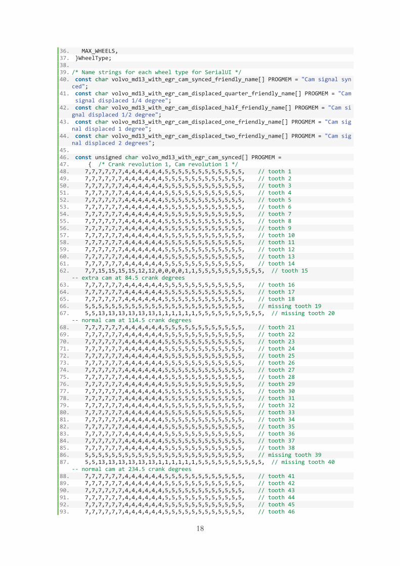
18
36. MAX_WHEELS, 37. }WheelType; 38. 39. /* Name strings for each wheel type for SerialUI */ 40. const char volvo_md13_with_egr_cam_synced_friendly_name[] PROGMEM = "Cam signal syn
ced"; 41. const char volvo_md13_with_egr_cam_displaced_quarter_friendly_name[] PROGMEM = "Cam
signal displaced 1/4 degree"; 42. const char volvo_md13_with_egr_cam_displaced_half_friendly_name[] PROGMEM = "Cam si
gnal displaced 1/2 degree"; 43. const char volvo_md13_with_egr_cam_displaced_one_friendly_name[] PROGMEM = "Cam sig
nal displaced 1 degree"; 44. const char volvo_md13_with_egr_cam_displaced_two_friendly_name[] PROGMEM = "Cam sig
nal displaced 2 degrees"; 45. 46. const unsigned char volvo_md13_with_egr_cam_synced[] PROGMEM = 47. { /* Crank revolution 1, Cam revolution 1 */ 48. 7,7,7,7,7,7,4,4,4,4,4,4,5,5,5,5,5,5,5,5,5,5,5,5, // tooth 1 49. 7,7,7,7,7,7,4,4,4,4,4,4,5,5,5,5,5,5,5,5,5,5,5,5, // tooth 2 50. 7,7,7,7,7,7,4,4,4,4,4,4,5,5,5,5,5,5,5,5,5,5,5,5, // tooth 3 51. 7,7,7,7,7,7,4,4,4,4,4,4,5,5,5,5,5,5,5,5,5,5,5,5, // tooth 4 52. 7,7,7,7,7,7,4,4,4,4,4,4,5,5,5,5,5,5,5,5,5,5,5,5, // tooth 5 53. 7,7,7,7,7,7,4,4,4,4,4,4,5,5,5,5,5,5,5,5,5,5,5,5, // tooth 6 54. 7,7,7,7,7,7,4,4,4,4,4,4,5,5,5,5,5,5,5,5,5,5,5,5, // tooth 7 55. 7,7,7,7,7,7,4,4,4,4,4,4,5,5,5,5,5,5,5,5,5,5,5,5, // tooth 8 56. 7,7,7,7,7,7,4,4,4,4,4,4,5,5,5,5,5,5,5,5,5,5,5,5, // tooth 9 57. 7,7,7,7,7,7,4,4,4,4,4,4,5,5,5,5,5,5,5,5,5,5,5,5, // tooth 10 58. 7,7,7,7,7,7,4,4,4,4,4,4,5,5,5,5,5,5,5,5,5,5,5,5, // tooth 11 59. 7,7,7,7,7,7,4,4,4,4,4,4,5,5,5,5,5,5,5,5,5,5,5,5, // tooth 12 60. 7,7,7,7,7,7,4,4,4,4,4,4,5,5,5,5,5,5,5,5,5,5,5,5, // tooth 13 61. 7,7,7,7,7,7,4,4,4,4,4,4,5,5,5,5,5,5,5,5,5,5,5,5, // tooth 14 62. 7,7,15,15,15,15,12,12,0,0,0,0,1,1,5,5,5,5,5,5,5,5,5,5, // tooth 15
-- extra cam at 84.5 crank degrees 63. 7,7,7,7,7,7,4,4,4,4,4,4,5,5,5,5,5,5,5,5,5,5,5,5, // tooth 16 64. 7,7,7,7,7,7,4,4,4,4,4,4,5,5,5,5,5,5,5,5,5,5,5,5, // tooth 17 65. 7,7,7,7,7,7,4,4,4,4,4,4,5,5,5,5,5,5,5,5,5,5,5,5, // tooth 18 66. 5,5,5,5,5,5,5,5,5,5,5,5,5,5,5,5,5,5,5,5,5,5,5,5, // missing tooth 19 67. 5,5,13,13,13,13,13,13,1,1,1,1,1,1,5,5,5,5,5,5,5,5,5,5, // missing tooth 20
-- normal cam at 114.5 crank degrees 68. 7,7,7,7,7,7,4,4,4,4,4,4,5,5,5,5,5,5,5,5,5,5,5,5, // tooth 21 69. 7,7,7,7,7,7,4,4,4,4,4,4,5,5,5,5,5,5,5,5,5,5,5,5, // tooth 22 70. 7,7,7,7,7,7,4,4,4,4,4,4,5,5,5,5,5,5,5,5,5,5,5,5, // tooth 23 71. 7,7,7,7,7,7,4,4,4,4,4,4,5,5,5,5,5,5,5,5,5,5,5,5, // tooth 24 72. 7,7,7,7,7,7,4,4,4,4,4,4,5,5,5,5,5,5,5,5,5,5,5,5, // tooth 25 73. 7,7,7,7,7,7,4,4,4,4,4,4,5,5,5,5,5,5,5,5,5,5,5,5, // tooth 26 74. 7,7,7,7,7,7,4,4,4,4,4,4,5,5,5,5,5,5,5,5,5,5,5,5, // tooth 27 75. 7,7,7,7,7,7,4,4,4,4,4,4,5,5,5,5,5,5,5,5,5,5,5,5, // tooth 28 76. 7,7,7,7,7,7,4,4,4,4,4,4,5,5,5,5,5,5,5,5,5,5,5,5, // tooth 29 77. 7,7,7,7,7,7,4,4,4,4,4,4,5,5,5,5,5,5,5,5,5,5,5,5, // tooth 30 78. 7,7,7,7,7,7,4,4,4,4,4,4,5,5,5,5,5,5,5,5,5,5,5,5, // tooth 31 79. 7,7,7,7,7,7,4,4,4,4,4,4,5,5,5,5,5,5,5,5,5,5,5,5, // tooth 32 80. 7,7,7,7,7,7,4,4,4,4,4,4,5,5,5,5,5,5,5,5,5,5,5,5, // tooth 33 81. 7,7,7,7,7,7,4,4,4,4,4,4,5,5,5,5,5,5,5,5,5,5,5,5, // tooth 34 82. 7,7,7,7,7,7,4,4,4,4,4,4,5,5,5,5,5,5,5,5,5,5,5,5, // tooth 35 83. 7,7,7,7,7,7,4,4,4,4,4,4,5,5,5,5,5,5,5,5,5,5,5,5, // tooth 36 84. 7,7,7,7,7,7,4,4,4,4,4,4,5,5,5,5,5,5,5,5,5,5,5,5, // tooth 37 85. 7,7,7,7,7,7,4,4,4,4,4,4,5,5,5,5,5,5,5,5,5,5,5,5, // tooth 38 86. 5,5,5,5,5,5,5,5,5,5,5,5,5,5,5,5,5,5,5,5,5,5,5,5, // missing tooth 39 87. 5,5,13,13,13,13,13,13,1,1,1,1,1,1,5,5,5,5,5,5,5,5,5,5, // missing tooth 40
-- normal cam at 234.5 crank degrees 88. 7,7,7,7,7,7,4,4,4,4,4,4,5,5,5,5,5,5,5,5,5,5,5,5, // tooth 41 89. 7,7,7,7,7,7,4,4,4,4,4,4,5,5,5,5,5,5,5,5,5,5,5,5, // tooth 42 90. 7,7,7,7,7,7,4,4,4,4,4,4,5,5,5,5,5,5,5,5,5,5,5,5, // tooth 43 91. 7,7,7,7,7,7,4,4,4,4,4,4,5,5,5,5,5,5,5,5,5,5,5,5, // tooth 44 92. 7,7,7,7,7,7,4,4,4,4,4,4,5,5,5,5,5,5,5,5,5,5,5,5, // tooth 45 93. 7,7,7,7,7,7,4,4,4,4,4,4,5,5,5,5,5,5,5,5,5,5,5,5, // tooth 46

19
94. 7,7,7,7,7,7,4,4,4,4,4,4,5,5,5,5,5,5,5,5,5,5,5,5, // tooth 47 95. 7,7,7,7,7,7,4,4,4,4,4,4,5,5,5,5,5,5,5,5,5,5,5,5, // tooth 48 96. 7,7,7,7,7,7,4,4,4,4,4,4,5,5,5,5,5,5,5,5,5,5,5,5, // tooth 49 97. 7,7,7,7,7,7,4,4,4,4,4,4,5,5,5,5,5,5,5,5,5,5,5,5, // tooth 50 98. 7,7,7,7,7,7,4,4,4,4,4,4,5,5,5,5,5,5,5,5,5,5,5,5, // tooth 51 99. 7,7,7,7,7,7,4,4,4,4,4,4,5,5,5,5,5,5,5,5,5,5,5,5, // tooth 52 100. 7,7,7,7,7,7,4,4,4,4,4,4,5,5,5,5,5,5,5,5,5,5,5,5, // tooth 53 101. 7,7,7,7,7,7,4,4,4,4,4,4,5,5,5,5,5,5,5,5,5,5,5,5, // tooth 54 102. 7,7,7,7,7,7,4,4,4,4,4,4,5,5,5,5,5,5,5,5,5,5,5,5, // tooth 55 103. 7,7,7,7,7,7,4,4,4,4,4,4,5,5,5,5,5,5,5,5,5,5,5,5, // tooth 56 104. 7,7,7,7,7,7,4,4,4,4,4,4,5,5,5,5,5,5,5,5,5,5,5,5, // tooth 57 105. 7,7,7,7,7,7,4,4,4,4,4,4,5,5,5,5,5,5,5,5,5,5,5,5, // tooth 58 106. 5,5,5,5,5,5,5,5,5,5,5,5,5,5,5,5,5,5,5,5,5,5,5,5, // missing tooth 59 107. 5,5,13,13,13,13,13,13,1,1,1,1,1,1,5,5,5,5,5,5,5,5,5,5, // missing tooth 6
0 -- normal cam at 354.5 crank degrees 108. 109. /* Crank revolution 2, Cam revolution 1 */ 110. 7,7,7,7,7,7,4,4,4,4,4,4,5,5,5,5,5,5,5,5,5,5,5,5, // tooth 1 111. 7,7,7,7,7,7,4,4,4,4,4,4,5,5,5,5,5,5,5,5,5,5,5,5, // tooth 2 112. 7,7,7,7,7,7,4,4,4,4,4,4,5,5,5,5,5,5,5,5,5,5,5,5, // tooth 3 113. 7,7,7,7,7,7,4,4,4,4,4,4,5,5,5,5,5,5,5,5,5,5,5,5, // tooth 4 114. 7,7,7,7,7,7,4,4,4,4,4,4,5,5,5,5,5,5,5,5,5,5,5,5, // tooth 5 115. 7,7,7,7,7,7,4,4,4,4,4,4,5,5,5,5,5,5,5,5,5,5,5,5, // tooth 6 116. 7,7,7,7,7,7,4,4,4,4,4,4,5,5,5,5,5,5,5,5,5,5,5,5, // tooth 7 117. 7,7,7,7,7,7,4,4,4,4,4,4,5,5,5,5,5,5,5,5,5,5,5,5, // tooth 8 118. 7,7,7,7,7,7,4,4,4,4,4,4,5,5,5,5,5,5,5,5,5,5,5,5, // tooth 9 119. 7,7,7,7,7,7,4,4,4,4,4,4,5,5,5,5,5,5,5,5,5,5,5,5, // tooth 10 120. 7,7,7,7,7,7,4,4,4,4,4,4,5,5,5,5,5,5,5,5,5,5,5,5, // tooth 11 121. 7,7,7,7,7,7,4,4,4,4,4,4,5,5,5,5,5,5,5,5,5,5,5,5, // tooth 12 122. 7,7,7,7,7,7,4,4,4,4,4,4,5,5,5,5,5,5,5,5,5,5,5,5, // tooth 13 123. 7,7,7,7,7,7,4,4,4,4,4,4,5,5,5,5,5,5,5,5,5,5,5,5, // tooth 14 124. 7,7,7,7,7,7,4,4,4,4,4,4,5,5,5,5,5,5,5,5,5,5,5,5, // tooth 15 125. 7,7,7,7,7,7,4,4,4,4,4,4,5,5,5,5,5,5,5,5,5,5,5,5, // tooth 16 126. 7,7,7,7,7,7,4,4,4,4,4,4,5,5,5,5,5,5,5,5,5,5,5,5, // tooth 17 127. 7,7,7,7,7,7,4,4,4,4,4,4,5,5,5,5,5,5,5,5,5,5,5,5, // tooth 18 128. 5,5,5,5,5,5,5,5,5,5,5,5,5,5,5,5,5,5,5,5,5,5,5,5, // missing tooth 19 129. 5,5,13,13,13,13,13,13,1,1,1,1,1,1,5,5,5,5,5,5,5,5,5,5, // missing tooth 2
0 -- normal cam at 114.5 crank degrees 130. 7,7,7,7,7,7,4,4,4,4,4,4,5,5,5,5,5,5,5,5,5,5,5,5, // tooth 21 131. 7,7,7,7,7,7,4,4,4,4,4,4,5,5,5,5,5,5,5,5,5,5,5,5, // tooth 22 132. 7,7,7,7,7,7,4,4,4,4,4,4,5,5,5,5,5,5,5,5,5,5,5,5, // tooth 23 133. 7,7,7,7,7,7,4,4,4,4,4,4,5,5,5,5,5,5,5,5,5,5,5,5, // tooth 24 134. 7,7,7,7,7,7,4,4,4,4,4,4,5,5,5,5,5,5,5,5,5,5,5,5, // tooth 25 135. 7,7,7,7,7,7,4,4,4,4,4,4,5,5,5,5,5,5,5,5,5,5,5,5, // tooth 26 136. 7,7,7,7,7,7,4,4,4,4,4,4,5,5,5,5,5,5,5,5,5,5,5,5, // tooth 27 137. 7,7,7,7,7,7,4,4,4,4,4,4,5,5,5,5,5,5,5,5,5,5,5,5, // tooth 28 138. 7,7,7,7,7,7,4,4,4,4,4,4,5,5,5,5,5,5,5,5,5,5,5,5, // tooth 29 139. 7,7,7,7,7,7,4,4,4,4,4,4,5,5,5,5,5,5,5,5,5,5,5,5, // tooth 30 140. 7,7,7,7,7,7,4,4,4,4,4,4,5,5,5,5,5,5,5,5,5,5,5,5, // tooth 31 141. 7,7,7,7,7,7,4,4,4,4,4,4,5,5,5,5,5,5,5,5,5,5,5,5, // tooth 32 142. 7,7,7,7,7,7,4,4,4,4,4,4,5,5,5,5,5,5,5,5,5,5,5,5, // tooth 33 143. 7,7,7,7,7,7,4,4,4,4,4,4,5,5,5,5,5,5,5,5,5,5,5,5, // tooth 34 144. 7,7,7,7,7,7,4,4,4,4,4,4,5,5,5,5,5,5,5,5,5,5,5,5, // tooth 35 145. 7,7,7,7,7,7,4,4,4,4,4,4,5,5,5,5,5,5,5,5,5,5,5,5, // tooth 36 146. 7,7,7,7,7,7,4,4,4,4,4,4,5,5,5,5,5,5,5,5,5,5,5,5, // tooth 37 147. 7,7,7,7,7,7,4,4,4,4,4,4,5,5,5,5,5,5,5,5,5,5,5,5, // tooth 38 148. 5,5,5,5,5,5,5,5,5,5,5,5,5,5,5,5,5,5,5,5,5,5,5,5, // missing tooth 39 149. 5,5,13,13,13,13,13,13,1,1,1,1,1,1,5,5,5,5,5,5,5,5,5,5, // missing tooth 4
0 -- normal cam at 234.5 crank degrees 150. 7,7,7,7,7,7,4,4,4,4,4,4,5,5,5,5,5,5,5,5,5,5,5,5, // tooth 41 151. 7,7,7,7,7,7,4,4,4,4,4,4,5,5,5,5,5,5,5,5,5,5,5,5, // tooth 42 152. 7,7,7,7,7,7,4,4,4,4,4,4,5,5,5,5,5,5,5,5,5,5,5,5, // tooth 43 153. 7,7,7,7,7,7,4,4,4,4,4,4,5,5,5,5,5,5,5,5,5,5,5,5, // tooth 44 154. 7,7,7,7,7,7,4,4,4,4,4,4,5,5,5,5,5,5,5,5,5,5,5,5, // tooth 45 155. 7,7,7,7,7,7,4,4,4,4,4,4,5,5,5,5,5,5,5,5,5,5,5,5, // tooth 46 156. 7,7,7,7,7,7,4,4,4,4,4,4,5,5,5,5,5,5,5,5,5,5,5,5, // tooth 47

20
157. 7,7,7,7,7,7,4,4,4,4,4,4,5,5,5,5,5,5,5,5,5,5,5,5, // tooth 48 158. 7,7,7,7,7,7,4,4,4,4,4,4,5,5,5,5,5,5,5,5,5,5,5,5, // tooth 49 159. 7,7,7,7,7,7,4,4,4,4,4,4,5,5,5,5,5,5,5,5,5,5,5,5, // tooth 50 160. 7,7,7,7,7,7,4,4,4,4,4,4,5,5,5,5,5,5,5,5,5,5,5,5, // tooth 51 161. 7,7,7,7,7,7,4,4,4,4,4,4,5,5,5,5,5,5,5,5,5,5,5,5, // tooth 52 162. 7,7,7,7,7,7,4,4,4,4,4,4,5,5,5,5,5,5,5,5,5,5,5,5, // tooth 53 163. 7,7,7,7,7,7,4,4,4,4,4,4,5,5,5,5,5,5,5,5,5,5,5,5, // tooth 54 164. 7,7,7,7,7,7,4,4,4,4,4,4,5,5,5,5,5,5,5,5,5,5,5,5, // tooth 55 165. 7,7,7,7,7,7,4,4,4,4,4,4,5,5,5,5,5,5,5,5,5,5,5,5, // tooth 56 166. 7,7,7,7,7,7,4,4,4,4,4,4,5,5,5,5,5,5,5,5,5,5,5,5, // tooth 57 167. 7,7,7,7,7,7,4,4,4,4,4,4,5,5,5,5,5,5,5,5,5,5,5,5, // tooth 58 168. 5,5,5,5,5,5,5,5,5,5,5,5,5,5,5,5,5,5,5,5,5,5,5,5, // missing tooth 59 169. 5,5,13,13,13,13,13,13,1,1,1,1,1,1,5,5,5,5,5,5,5,5,5,5, // missing tooth 6
0 -- normal cam at 354.5 crank degrees 170. }; 171. 172. const unsigned char volvo_md13_with_egr_cam_displaced_quarter[] PROGMEM = 173. { /* Crank revolution 1, Cam revolution 1 */ 174. 7,7,7,7,7,7,4,4,4,4,4,4,5,5,5,5,5,5,5,5,5,5,5,5, // tooth 1 175. 7,7,7,7,7,7,4,4,4,4,4,4,5,5,5,5,5,5,5,5,5,5,5,5, // tooth 2 176. 7,7,7,7,7,7,4,4,4,4,4,4,5,5,5,5,5,5,5,5,5,5,5,5, // tooth 3 177. 7,7,7,7,7,7,4,4,4,4,4,4,5,5,5,5,5,5,5,5,5,5,5,5, // tooth 4 178. 7,7,7,7,7,7,4,4,4,4,4,4,5,5,5,5,5,5,5,5,5,5,5,5, // tooth 5 179. 7,7,7,7,7,7,4,4,4,4,4,4,5,5,5,5,5,5,5,5,5,5,5,5, // tooth 6 180. 7,7,7,7,7,7,4,4,4,4,4,4,5,5,5,5,5,5,5,5,5,5,5,5, // tooth 7 181. 7,7,7,7,7,7,4,4,4,4,4,4,5,5,5,5,5,5,5,5,5,5,5,5, // tooth 8 182. 7,7,7,7,7,7,4,4,4,4,4,4,5,5,5,5,5,5,5,5,5,5,5,5, // tooth 9 183. 7,7,7,7,7,7,4,4,4,4,4,4,5,5,5,5,5,5,5,5,5,5,5,5, // tooth 10 184. 7,7,7,7,7,7,4,4,4,4,4,4,5,5,5,5,5,5,5,5,5,5,5,5, // tooth 11 185. 7,7,7,7,7,7,4,4,4,4,4,4,5,5,5,5,5,5,5,5,5,5,5,5, // tooth 12 186. 7,7,7,7,7,7,4,4,4,4,4,4,5,5,5,5,5,5,5,5,5,5,5,5, // tooth 13 187. 7,7,7,7,7,7,4,4,4,4,4,4,5,5,5,5,5,5,5,5,5,5,5,5, // tooth 14 188. 7,7,7,15,15,15,12,12,12,0,0,0,1,1,1,5,5,5,5,5,5,5,5,5, // tooth 15
-- extra cam at 84.75 crank degrees 189. 7,7,7,7,7,7,4,4,4,4,4,4,5,5,5,5,5,5,5,5,5,5,5,5, // tooth 16 190. 7,7,7,7,7,7,4,4,4,4,4,4,5,5,5,5,5,5,5,5,5,5,5,5, // tooth 17 191. 7,7,7,7,7,7,4,4,4,4,4,4,5,5,5,5,5,5,5,5,5,5,5,5, // tooth 18 192. 5,5,5,5,5,5,5,5,5,5,5,5,5,5,5,5,5,5,5,5,5,5,5,5, // missing tooth 19 193. 5,5,5,13,13,13,13,13,13,1,1,1,1,1,1,5,5,5,5,5,5,5,5,5, // missing tooth 2
0 -- normal cam at 114.75 crank degrees 194. 7,7,7,7,7,7,4,4,4,4,4,4,5,5,5,5,5,5,5,5,5,5,5,5, // tooth 21 195. 7,7,7,7,7,7,4,4,4,4,4,4,5,5,5,5,5,5,5,5,5,5,5,5, // tooth 22 196. 7,7,7,7,7,7,4,4,4,4,4,4,5,5,5,5,5,5,5,5,5,5,5,5, // tooth 23 197. 7,7,7,7,7,7,4,4,4,4,4,4,5,5,5,5,5,5,5,5,5,5,5,5, // tooth 24 198. 7,7,7,7,7,7,4,4,4,4,4,4,5,5,5,5,5,5,5,5,5,5,5,5, // tooth 25 199. 7,7,7,7,7,7,4,4,4,4,4,4,5,5,5,5,5,5,5,5,5,5,5,5, // tooth 26 200. 7,7,7,7,7,7,4,4,4,4,4,4,5,5,5,5,5,5,5,5,5,5,5,5, // tooth 27 201. 7,7,7,7,7,7,4,4,4,4,4,4,5,5,5,5,5,5,5,5,5,5,5,5, // tooth 28 202. 7,7,7,7,7,7,4,4,4,4,4,4,5,5,5,5,5,5,5,5,5,5,5,5, // tooth 29 203. 7,7,7,7,7,7,4,4,4,4,4,4,5,5,5,5,5,5,5,5,5,5,5,5, // tooth 30 204. 7,7,7,7,7,7,4,4,4,4,4,4,5,5,5,5,5,5,5,5,5,5,5,5, // tooth 31 205. 7,7,7,7,7,7,4,4,4,4,4,4,5,5,5,5,5,5,5,5,5,5,5,5, // tooth 32 206. 7,7,7,7,7,7,4,4,4,4,4,4,5,5,5,5,5,5,5,5,5,5,5,5, // tooth 33 207. 7,7,7,7,7,7,4,4,4,4,4,4,5,5,5,5,5,5,5,5,5,5,5,5, // tooth 34 208. 7,7,7,7,7,7,4,4,4,4,4,4,5,5,5,5,5,5,5,5,5,5,5,5, // tooth 35 209. 7,7,7,7,7,7,4,4,4,4,4,4,5,5,5,5,5,5,5,5,5,5,5,5, // tooth 36 210. 7,7,7,7,7,7,4,4,4,4,4,4,5,5,5,5,5,5,5,5,5,5,5,5, // tooth 37 211. 7,7,7,7,7,7,4,4,4,4,4,4,5,5,5,5,5,5,5,5,5,5,5,5, // tooth 38 212. 5,5,5,5,5,5,5,5,5,5,5,5,5,5,5,5,5,5,5,5,5,5,5,5, // missing tooth 39 213. 5,5,5,13,13,13,13,13,13,1,1,1,1,1,1,5,5,5,5,5,5,5,5,5, // missing tooth 4
0 -- normal cam at 234.75 crank degrees 214. 7,7,7,7,7,7,4,4,4,4,4,4,5,5,5,5,5,5,5,5,5,5,5,5, // tooth 41 215. 7,7,7,7,7,7,4,4,4,4,4,4,5,5,5,5,5,5,5,5,5,5,5,5, // tooth 42 216. 7,7,7,7,7,7,4,4,4,4,4,4,5,5,5,5,5,5,5,5,5,5,5,5, // tooth 43 217. 7,7,7,7,7,7,4,4,4,4,4,4,5,5,5,5,5,5,5,5,5,5,5,5, // tooth 44 218. 7,7,7,7,7,7,4,4,4,4,4,4,5,5,5,5,5,5,5,5,5,5,5,5, // tooth 45

21
219. 7,7,7,7,7,7,4,4,4,4,4,4,5,5,5,5,5,5,5,5,5,5,5,5, // tooth 46 220. 7,7,7,7,7,7,4,4,4,4,4,4,5,5,5,5,5,5,5,5,5,5,5,5, // tooth 47 221. 7,7,7,7,7,7,4,4,4,4,4,4,5,5,5,5,5,5,5,5,5,5,5,5, // tooth 48 222. 7,7,7,7,7,7,4,4,4,4,4,4,5,5,5,5,5,5,5,5,5,5,5,5, // tooth 49 223. 7,7,7,7,7,7,4,4,4,4,4,4,5,5,5,5,5,5,5,5,5,5,5,5, // tooth 50 224. 7,7,7,7,7,7,4,4,4,4,4,4,5,5,5,5,5,5,5,5,5,5,5,5, // tooth 51 225. 7,7,7,7,7,7,4,4,4,4,4,4,5,5,5,5,5,5,5,5,5,5,5,5, // tooth 52 226. 7,7,7,7,7,7,4,4,4,4,4,4,5,5,5,5,5,5,5,5,5,5,5,5, // tooth 53 227. 7,7,7,7,7,7,4,4,4,4,4,4,5,5,5,5,5,5,5,5,5,5,5,5, // tooth 54 228. 7,7,7,7,7,7,4,4,4,4,4,4,5,5,5,5,5,5,5,5,5,5,5,5, // tooth 55 229. 7,7,7,7,7,7,4,4,4,4,4,4,5,5,5,5,5,5,5,5,5,5,5,5, // tooth 56 230. 7,7,7,7,7,7,4,4,4,4,4,4,5,5,5,5,5,5,5,5,5,5,5,5, // tooth 57 231. 7,7,7,7,7,7,4,4,4,4,4,4,5,5,5,5,5,5,5,5,5,5,5,5, // tooth 58 232. 5,5,5,5,5,5,5,5,5,5,5,5,5,5,5,5,5,5,5,5,5,5,5,5, // missing tooth 59 233. 5,5,5,13,13,13,13,13,13,1,1,1,1,1,1,5,5,5,5,5,5,5,5,5, // missing tooth 6
0 -- normal cam at 354.75 crank degrees 234. 235. /* Crank revolution 2, Cam revolution 1 */ 236. 7,7,7,7,7,7,4,4,4,4,4,4,5,5,5,5,5,5,5,5,5,5,5,5, // tooth 1 237. 7,7,7,7,7,7,4,4,4,4,4,4,5,5,5,5,5,5,5,5,5,5,5,5, // tooth 2 238. 7,7,7,7,7,7,4,4,4,4,4,4,5,5,5,5,5,5,5,5,5,5,5,5, // tooth 3 239. 7,7,7,7,7,7,4,4,4,4,4,4,5,5,5,5,5,5,5,5,5,5,5,5, // tooth 4 240. 7,7,7,7,7,7,4,4,4,4,4,4,5,5,5,5,5,5,5,5,5,5,5,5, // tooth 5 241. 7,7,7,7,7,7,4,4,4,4,4,4,5,5,5,5,5,5,5,5,5,5,5,5, // tooth 6 242. 7,7,7,7,7,7,4,4,4,4,4,4,5,5,5,5,5,5,5,5,5,5,5,5, // tooth 7 243. 7,7,7,7,7,7,4,4,4,4,4,4,5,5,5,5,5,5,5,5,5,5,5,5, // tooth 8 244. 7,7,7,7,7,7,4,4,4,4,4,4,5,5,5,5,5,5,5,5,5,5,5,5, // tooth 9 245. 7,7,7,7,7,7,4,4,4,4,4,4,5,5,5,5,5,5,5,5,5,5,5,5, // tooth 10 246. 7,7,7,7,7,7,4,4,4,4,4,4,5,5,5,5,5,5,5,5,5,5,5,5, // tooth 11 247. 7,7,7,7,7,7,4,4,4,4,4,4,5,5,5,5,5,5,5,5,5,5,5,5, // tooth 12 248. 7,7,7,7,7,7,4,4,4,4,4,4,5,5,5,5,5,5,5,5,5,5,5,5, // tooth 13 249. 7,7,7,7,7,7,4,4,4,4,4,4,5,5,5,5,5,5,5,5,5,5,5,5, // tooth 14 250. 7,7,7,7,7,7,4,4,4,4,4,4,5,5,5,5,5,5,5,5,5,5,5,5, // tooth 15 251. 7,7,7,7,7,7,4,4,4,4,4,4,5,5,5,5,5,5,5,5,5,5,5,5, // tooth 16 252. 7,7,7,7,7,7,4,4,4,4,4,4,5,5,5,5,5,5,5,5,5,5,5,5, // tooth 17 253. 7,7,7,7,7,7,4,4,4,4,4,4,5,5,5,5,5,5,5,5,5,5,5,5, // tooth 18 254. 5,5,5,5,5,5,5,5,5,5,5,5,5,5,5,5,5,5,5,5,5,5,5,5, // missing tooth 19 255. 5,5,5,13,13,13,13,13,13,1,1,1,1,1,1,5,5,5,5,5,5,5,5,5, // missing tooth 2
0 -- normal cam at 114.75 crank degrees 256. 7,7,7,7,7,7,4,4,4,4,4,4,5,5,5,5,5,5,5,5,5,5,5,5, // tooth 21 257. 7,7,7,7,7,7,4,4,4,4,4,4,5,5,5,5,5,5,5,5,5,5,5,5, // tooth 22 258. 7,7,7,7,7,7,4,4,4,4,4,4,5,5,5,5,5,5,5,5,5,5,5,5, // tooth 23 259. 7,7,7,7,7,7,4,4,4,4,4,4,5,5,5,5,5,5,5,5,5,5,5,5, // tooth 24 260. 7,7,7,7,7,7,4,4,4,4,4,4,5,5,5,5,5,5,5,5,5,5,5,5, // tooth 25 261. 7,7,7,7,7,7,4,4,4,4,4,4,5,5,5,5,5,5,5,5,5,5,5,5, // tooth 26 262. 7,7,7,7,7,7,4,4,4,4,4,4,5,5,5,5,5,5,5,5,5,5,5,5, // tooth 27 263. 7,7,7,7,7,7,4,4,4,4,4,4,5,5,5,5,5,5,5,5,5,5,5,5, // tooth 28 264. 7,7,7,7,7,7,4,4,4,4,4,4,5,5,5,5,5,5,5,5,5,5,5,5, // tooth 29 265. 7,7,7,7,7,7,4,4,4,4,4,4,5,5,5,5,5,5,5,5,5,5,5,5, // tooth 30 266. 7,7,7,7,7,7,4,4,4,4,4,4,5,5,5,5,5,5,5,5,5,5,5,5, // tooth 31 267. 7,7,7,7,7,7,4,4,4,4,4,4,5,5,5,5,5,5,5,5,5,5,5,5, // tooth 32 268. 7,7,7,7,7,7,4,4,4,4,4,4,5,5,5,5,5,5,5,5,5,5,5,5, // tooth 33 269. 7,7,7,7,7,7,4,4,4,4,4,4,5,5,5,5,5,5,5,5,5,5,5,5, // tooth 34 270. 7,7,7,7,7,7,4,4,4,4,4,4,5,5,5,5,5,5,5,5,5,5,5,5, // tooth 35 271. 7,7,7,7,7,7,4,4,4,4,4,4,5,5,5,5,5,5,5,5,5,5,5,5, // tooth 36 272. 7,7,7,7,7,7,4,4,4,4,4,4,5,5,5,5,5,5,5,5,5,5,5,5, // tooth 37 273. 7,7,7,7,7,7,4,4,4,4,4,4,5,5,5,5,5,5,5,5,5,5,5,5, // tooth 38 274. 5,5,5,5,5,5,5,5,5,5,5,5,5,5,5,5,5,5,5,5,5,5,5,5, // missing tooth 39 275. 5,5,5,13,13,13,13,13,13,1,1,1,1,1,1,5,5,5,5,5,5,5,5,5, // missing tooth 4
0 -- normal cam at 234.75 crank degrees 276. 7,7,7,7,7,7,4,4,4,4,4,4,5,5,5,5,5,5,5,5,5,5,5,5, // tooth 41 277. 7,7,7,7,7,7,4,4,4,4,4,4,5,5,5,5,5,5,5,5,5,5,5,5, // tooth 42 278. 7,7,7,7,7,7,4,4,4,4,4,4,5,5,5,5,5,5,5,5,5,5,5,5, // tooth 43 279. 7,7,7,7,7,7,4,4,4,4,4,4,5,5,5,5,5,5,5,5,5,5,5,5, // tooth 44 280. 7,7,7,7,7,7,4,4,4,4,4,4,5,5,5,5,5,5,5,5,5,5,5,5, // tooth 45 281. 7,7,7,7,7,7,4,4,4,4,4,4,5,5,5,5,5,5,5,5,5,5,5,5, // tooth 46

22
282. 7,7,7,7,7,7,4,4,4,4,4,4,5,5,5,5,5,5,5,5,5,5,5,5, // tooth 47 283. 7,7,7,7,7,7,4,4,4,4,4,4,5,5,5,5,5,5,5,5,5,5,5,5, // tooth 48 284. 7,7,7,7,7,7,4,4,4,4,4,4,5,5,5,5,5,5,5,5,5,5,5,5, // tooth 49 285. 7,7,7,7,7,7,4,4,4,4,4,4,5,5,5,5,5,5,5,5,5,5,5,5, // tooth 50 286. 7,7,7,7,7,7,4,4,4,4,4,4,5,5,5,5,5,5,5,5,5,5,5,5, // tooth 51 287. 7,7,7,7,7,7,4,4,4,4,4,4,5,5,5,5,5,5,5,5,5,5,5,5, // tooth 52 288. 7,7,7,7,7,7,4,4,4,4,4,4,5,5,5,5,5,5,5,5,5,5,5,5, // tooth 53 289. 7,7,7,7,7,7,4,4,4,4,4,4,5,5,5,5,5,5,5,5,5,5,5,5, // tooth 54 290. 7,7,7,7,7,7,4,4,4,4,4,4,5,5,5,5,5,5,5,5,5,5,5,5, // tooth 55 291. 7,7,7,7,7,7,4,4,4,4,4,4,5,5,5,5,5,5,5,5,5,5,5,5, // tooth 56 292. 7,7,7,7,7,7,4,4,4,4,4,4,5,5,5,5,5,5,5,5,5,5,5,5, // tooth 57 293. 7,7,7,7,7,7,4,4,4,4,4,4,5,5,5,5,5,5,5,5,5,5,5,5, // tooth 58 294. 5,5,5,5,5,5,5,5,5,5,5,5,5,5,5,5,5,5,5,5,5,5,5,5, // missing tooth 59 295. 5,5,5,13,13,13,13,13,13,1,1,1,1,1,1,5,5,5,5,5,5,5,5,5, // missing tooth 6
0 -- normal cam at 354.75 crank degrees 296. }; 297. 298. const unsigned char volvo_md13_with_egr_cam_displaced_half[] PROGMEM = 299. { /* Crank revolution 1, Cam revolution 1 */ 300. 7,7,7,7,7,7,4,4,4,4,4,4,5,5,5,5,5,5,5,5,5,5,5,5, // tooth 1 301. 7,7,7,7,7,7,4,4,4,4,4,4,5,5,5,5,5,5,5,5,5,5,5,5, // tooth 2 302. 7,7,7,7,7,7,4,4,4,4,4,4,5,5,5,5,5,5,5,5,5,5,5,5, // tooth 3 303. 7,7,7,7,7,7,4,4,4,4,4,4,5,5,5,5,5,5,5,5,5,5,5,5, // tooth 4 304. 7,7,7,7,7,7,4,4,4,4,4,4,5,5,5,5,5,5,5,5,5,5,5,5, // tooth 5 305. 7,7,7,7,7,7,4,4,4,4,4,4,5,5,5,5,5,5,5,5,5,5,5,5, // tooth 6 306. 7,7,7,7,7,7,4,4,4,4,4,4,5,5,5,5,5,5,5,5,5,5,5,5, // tooth 7 307. 7,7,7,7,7,7,4,4,4,4,4,4,5,5,5,5,5,5,5,5,5,5,5,5, // tooth 8 308. 7,7,7,7,7,7,4,4,4,4,4,4,5,5,5,5,5,5,5,5,5,5,5,5, // tooth 9 309. 7,7,7,7,7,7,4,4,4,4,4,4,5,5,5,5,5,5,5,5,5,5,5,5, // tooth 10 310. 7,7,7,7,7,7,4,4,4,4,4,4,5,5,5,5,5,5,5,5,5,5,5,5, // tooth 11 311. 7,7,7,7,7,7,4,4,4,4,4,4,5,5,5,5,5,5,5,5,5,5,5,5, // tooth 12 312. 7,7,7,7,7,7,4,4,4,4,4,4,5,5,5,5,5,5,5,5,5,5,5,5, // tooth 13 313. 7,7,7,7,7,7,4,4,4,4,4,4,5,5,5,5,5,5,5,5,5,5,5,5, // tooth 14 314. 7,7,7,7,15,15,12,12,12,12,0,0,1,1,1,1,5,5,5,5,5,5,5,5, // tooth 15
-- extra cam at 85 crank degrees 315. 7,7,7,7,7,7,4,4,4,4,4,4,5,5,5,5,5,5,5,5,5,5,5,5, // tooth 16 316. 7,7,7,7,7,7,4,4,4,4,4,4,5,5,5,5,5,5,5,5,5,5,5,5, // tooth 17 317. 7,7,7,7,7,7,4,4,4,4,4,4,5,5,5,5,5,5,5,5,5,5,5,5, // tooth 18 318. 5,5,5,5,5,5,5,5,5,5,5,5,5,5,5,5,5,5,5,5,5,5,5,5, // missing tooth 19 319. 5,5,5,5,13,13,13,13,13,13,1,1,1,1,1,1,5,5,5,5,5,5,5,5, // missing tooth 2
0 -- normal cam at 115 crank degrees 320. 7,7,7,7,7,7,4,4,4,4,4,4,5,5,5,5,5,5,5,5,5,5,5,5, // tooth 21 321. 7,7,7,7,7,7,4,4,4,4,4,4,5,5,5,5,5,5,5,5,5,5,5,5, // tooth 22 322. 7,7,7,7,7,7,4,4,4,4,4,4,5,5,5,5,5,5,5,5,5,5,5,5, // tooth 23 323. 7,7,7,7,7,7,4,4,4,4,4,4,5,5,5,5,5,5,5,5,5,5,5,5, // tooth 24 324. 7,7,7,7,7,7,4,4,4,4,4,4,5,5,5,5,5,5,5,5,5,5,5,5, // tooth 25 325. 7,7,7,7,7,7,4,4,4,4,4,4,5,5,5,5,5,5,5,5,5,5,5,5, // tooth 26 326. 7,7,7,7,7,7,4,4,4,4,4,4,5,5,5,5,5,5,5,5,5,5,5,5, // tooth 27 327. 7,7,7,7,7,7,4,4,4,4,4,4,5,5,5,5,5,5,5,5,5,5,5,5, // tooth 28 328. 7,7,7,7,7,7,4,4,4,4,4,4,5,5,5,5,5,5,5,5,5,5,5,5, // tooth 29 329. 7,7,7,7,7,7,4,4,4,4,4,4,5,5,5,5,5,5,5,5,5,5,5,5, // tooth 30 330. 7,7,7,7,7,7,4,4,4,4,4,4,5,5,5,5,5,5,5,5,5,5,5,5, // tooth 31 331. 7,7,7,7,7,7,4,4,4,4,4,4,5,5,5,5,5,5,5,5,5,5,5,5, // tooth 32 332. 7,7,7,7,7,7,4,4,4,4,4,4,5,5,5,5,5,5,5,5,5,5,5,5, // tooth 33 333. 7,7,7,7,7,7,4,4,4,4,4,4,5,5,5,5,5,5,5,5,5,5,5,5, // tooth 34 334. 7,7,7,7,7,7,4,4,4,4,4,4,5,5,5,5,5,5,5,5,5,5,5,5, // tooth 35 335. 7,7,7,7,7,7,4,4,4,4,4,4,5,5,5,5,5,5,5,5,5,5,5,5, // tooth 36 336. 7,7,7,7,7,7,4,4,4,4,4,4,5,5,5,5,5,5,5,5,5,5,5,5, // tooth 37 337. 7,7,7,7,7,7,4,4,4,4,4,4,5,5,5,5,5,5,5,5,5,5,5,5, // tooth 38 338. 5,5,5,5,5,5,5,5,5,5,5,5,5,5,5,5,5,5,5,5,5,5,5,5, // missing tooth 39 339. 5,5,5,5,13,13,13,13,13,13,1,1,1,1,1,1,5,5,5,5,5,5,5,5, // missing tooth 4
0 -- normal cam at 235 crank degrees 340. 7,7,7,7,7,7,4,4,4,4,4,4,5,5,5,5,5,5,5,5,5,5,5,5, // tooth 41 341. 7,7,7,7,7,7,4,4,4,4,4,4,5,5,5,5,5,5,5,5,5,5,5,5, // tooth 42 342. 7,7,7,7,7,7,4,4,4,4,4,4,5,5,5,5,5,5,5,5,5,5,5,5, // tooth 43 343. 7,7,7,7,7,7,4,4,4,4,4,4,5,5,5,5,5,5,5,5,5,5,5,5, // tooth 44

23
344. 7,7,7,7,7,7,4,4,4,4,4,4,5,5,5,5,5,5,5,5,5,5,5,5, // tooth 45 345. 7,7,7,7,7,7,4,4,4,4,4,4,5,5,5,5,5,5,5,5,5,5,5,5, // tooth 46 346. 7,7,7,7,7,7,4,4,4,4,4,4,5,5,5,5,5,5,5,5,5,5,5,5, // tooth 47 347. 7,7,7,7,7,7,4,4,4,4,4,4,5,5,5,5,5,5,5,5,5,5,5,5, // tooth 48 348. 7,7,7,7,7,7,4,4,4,4,4,4,5,5,5,5,5,5,5,5,5,5,5,5, // tooth 49 349. 7,7,7,7,7,7,4,4,4,4,4,4,5,5,5,5,5,5,5,5,5,5,5,5, // tooth 50 350. 7,7,7,7,7,7,4,4,4,4,4,4,5,5,5,5,5,5,5,5,5,5,5,5, // tooth 51 351. 7,7,7,7,7,7,4,4,4,4,4,4,5,5,5,5,5,5,5,5,5,5,5,5, // tooth 52 352. 7,7,7,7,7,7,4,4,4,4,4,4,5,5,5,5,5,5,5,5,5,5,5,5, // tooth 53 353. 7,7,7,7,7,7,4,4,4,4,4,4,5,5,5,5,5,5,5,5,5,5,5,5, // tooth 54 354. 7,7,7,7,7,7,4,4,4,4,4,4,5,5,5,5,5,5,5,5,5,5,5,5, // tooth 55 355. 7,7,7,7,7,7,4,4,4,4,4,4,5,5,5,5,5,5,5,5,5,5,5,5, // tooth 56 356. 7,7,7,7,7,7,4,4,4,4,4,4,5,5,5,5,5,5,5,5,5,5,5,5, // tooth 57 357. 7,7,7,7,7,7,4,4,4,4,4,4,5,5,5,5,5,5,5,5,5,5,5,5, // tooth 58 358. 5,5,5,5,5,5,5,5,5,5,5,5,5,5,5,5,5,5,5,5,5,5,5,5, // missing tooth 59 359. 5,5,5,5,13,13,13,13,13,13,1,1,1,1,1,1,5,5,5,5,5,5,5,5, // missing tooth 6
0 -- normal cam at 355 crank degrees 360. 361. /* Crank revolution 2, Cam revolution 1 */ 362. 7,7,7,7,7,7,4,4,4,4,4,4,5,5,5,5,5,5,5,5,5,5,5,5, // tooth 1 363. 7,7,7,7,7,7,4,4,4,4,4,4,5,5,5,5,5,5,5,5,5,5,5,5, // tooth 2 364. 7,7,7,7,7,7,4,4,4,4,4,4,5,5,5,5,5,5,5,5,5,5,5,5, // tooth 3 365. 7,7,7,7,7,7,4,4,4,4,4,4,5,5,5,5,5,5,5,5,5,5,5,5, // tooth 4 366. 7,7,7,7,7,7,4,4,4,4,4,4,5,5,5,5,5,5,5,5,5,5,5,5, // tooth 5 367. 7,7,7,7,7,7,4,4,4,4,4,4,5,5,5,5,5,5,5,5,5,5,5,5, // tooth 6 368. 7,7,7,7,7,7,4,4,4,4,4,4,5,5,5,5,5,5,5,5,5,5,5,5, // tooth 7 369. 7,7,7,7,7,7,4,4,4,4,4,4,5,5,5,5,5,5,5,5,5,5,5,5, // tooth 8 370. 7,7,7,7,7,7,4,4,4,4,4,4,5,5,5,5,5,5,5,5,5,5,5,5, // tooth 9 371. 7,7,7,7,7,7,4,4,4,4,4,4,5,5,5,5,5,5,5,5,5,5,5,5, // tooth 10 372. 7,7,7,7,7,7,4,4,4,4,4,4,5,5,5,5,5,5,5,5,5,5,5,5, // tooth 11 373. 7,7,7,7,7,7,4,4,4,4,4,4,5,5,5,5,5,5,5,5,5,5,5,5, // tooth 12 374. 7,7,7,7,7,7,4,4,4,4,4,4,5,5,5,5,5,5,5,5,5,5,5,5, // tooth 13 375. 7,7,7,7,7,7,4,4,4,4,4,4,5,5,5,5,5,5,5,5,5,5,5,5, // tooth 14 376. 7,7,7,7,7,7,4,4,4,4,4,4,5,5,5,5,5,5,5,5,5,5,5,5, // tooth 15 377. 7,7,7,7,7,7,4,4,4,4,4,4,5,5,5,5,5,5,5,5,5,5,5,5, // tooth 16 378. 7,7,7,7,7,7,4,4,4,4,4,4,5,5,5,5,5,5,5,5,5,5,5,5, // tooth 17 379. 7,7,7,7,7,7,4,4,4,4,4,4,5,5,5,5,5,5,5,5,5,5,5,5, // tooth 18 380. 5,5,5,5,5,5,5,5,5,5,5,5,5,5,5,5,5,5,5,5,5,5,5,5, // missing tooth 19 381. 5,5,5,5,13,13,13,13,13,13,1,1,1,1,1,1,5,5,5,5,5,5,5,5, // missing tooth 2
0 -- normal cam at 115 crank degrees 382. 7,7,7,7,7,7,4,4,4,4,4,4,5,5,5,5,5,5,5,5,5,5,5,5, // tooth 21 383. 7,7,7,7,7,7,4,4,4,4,4,4,5,5,5,5,5,5,5,5,5,5,5,5, // tooth 22 384. 7,7,7,7,7,7,4,4,4,4,4,4,5,5,5,5,5,5,5,5,5,5,5,5, // tooth 23 385. 7,7,7,7,7,7,4,4,4,4,4,4,5,5,5,5,5,5,5,5,5,5,5,5, // tooth 24 386. 7,7,7,7,7,7,4,4,4,4,4,4,5,5,5,5,5,5,5,5,5,5,5,5, // tooth 25 387. 7,7,7,7,7,7,4,4,4,4,4,4,5,5,5,5,5,5,5,5,5,5,5,5, // tooth 26 388. 7,7,7,7,7,7,4,4,4,4,4,4,5,5,5,5,5,5,5,5,5,5,5,5, // tooth 27 389. 7,7,7,7,7,7,4,4,4,4,4,4,5,5,5,5,5,5,5,5,5,5,5,5, // tooth 28 390. 7,7,7,7,7,7,4,4,4,4,4,4,5,5,5,5,5,5,5,5,5,5,5,5, // tooth 29 391. 7,7,7,7,7,7,4,4,4,4,4,4,5,5,5,5,5,5,5,5,5,5,5,5, // tooth 30 392. 7,7,7,7,7,7,4,4,4,4,4,4,5,5,5,5,5,5,5,5,5,5,5,5, // tooth 31 393. 7,7,7,7,7,7,4,4,4,4,4,4,5,5,5,5,5,5,5,5,5,5,5,5, // tooth 32 394. 7,7,7,7,7,7,4,4,4,4,4,4,5,5,5,5,5,5,5,5,5,5,5,5, // tooth 33 395. 7,7,7,7,7,7,4,4,4,4,4,4,5,5,5,5,5,5,5,5,5,5,5,5, // tooth 34 396. 7,7,7,7,7,7,4,4,4,4,4,4,5,5,5,5,5,5,5,5,5,5,5,5, // tooth 35 397. 7,7,7,7,7,7,4,4,4,4,4,4,5,5,5,5,5,5,5,5,5,5,5,5, // tooth 36 398. 7,7,7,7,7,7,4,4,4,4,4,4,5,5,5,5,5,5,5,5,5,5,5,5, // tooth 37 399. 7,7,7,7,7,7,4,4,4,4,4,4,5,5,5,5,5,5,5,5,5,5,5,5, // tooth 38 400. 5,5,5,5,5,5,5,5,5,5,5,5,5,5,5,5,5,5,5,5,5,5,5,5, // missing tooth 39 401. 5,5,5,5,13,13,13,13,13,13,1,1,1,1,1,1,5,5,5,5,5,5,5,5, // missing tooth 4
0 -- normal cam at 235 crank degrees 402. 7,7,7,7,7,7,4,4,4,4,4,4,5,5,5,5,5,5,5,5,5,5,5,5, // tooth 41 403. 7,7,7,7,7,7,4,4,4,4,4,4,5,5,5,5,5,5,5,5,5,5,5,5, // tooth 42 404. 7,7,7,7,7,7,4,4,4,4,4,4,5,5,5,5,5,5,5,5,5,5,5,5, // tooth 43 405. 7,7,7,7,7,7,4,4,4,4,4,4,5,5,5,5,5,5,5,5,5,5,5,5, // tooth 44 406. 7,7,7,7,7,7,4,4,4,4,4,4,5,5,5,5,5,5,5,5,5,5,5,5, // tooth 45

24
407. 7,7,7,7,7,7,4,4,4,4,4,4,5,5,5,5,5,5,5,5,5,5,5,5, // tooth 46 408. 7,7,7,7,7,7,4,4,4,4,4,4,5,5,5,5,5,5,5,5,5,5,5,5, // tooth 47 409. 7,7,7,7,7,7,4,4,4,4,4,4,5,5,5,5,5,5,5,5,5,5,5,5, // tooth 48 410. 7,7,7,7,7,7,4,4,4,4,4,4,5,5,5,5,5,5,5,5,5,5,5,5, // tooth 49 411. 7,7,7,7,7,7,4,4,4,4,4,4,5,5,5,5,5,5,5,5,5,5,5,5, // tooth 50 412. 7,7,7,7,7,7,4,4,4,4,4,4,5,5,5,5,5,5,5,5,5,5,5,5, // tooth 51 413. 7,7,7,7,7,7,4,4,4,4,4,4,5,5,5,5,5,5,5,5,5,5,5,5, // tooth 52 414. 7,7,7,7,7,7,4,4,4,4,4,4,5,5,5,5,5,5,5,5,5,5,5,5, // tooth 53 415. 7,7,7,7,7,7,4,4,4,4,4,4,5,5,5,5,5,5,5,5,5,5,5,5, // tooth 54 416. 7,7,7,7,7,7,4,4,4,4,4,4,5,5,5,5,5,5,5,5,5,5,5,5, // tooth 55 417. 7,7,7,7,7,7,4,4,4,4,4,4,5,5,5,5,5,5,5,5,5,5,5,5, // tooth 56 418. 7,7,7,7,7,7,4,4,4,4,4,4,5,5,5,5,5,5,5,5,5,5,5,5, // tooth 57 419. 7,7,7,7,7,7,4,4,4,4,4,4,5,5,5,5,5,5,5,5,5,5,5,5, // tooth 58 420. 5,5,5,5,5,5,5,5,5,5,5,5,5,5,5,5,5,5,5,5,5,5,5,5, // missing tooth 59 421. 5,5,5,5,13,13,13,13,13,13,1,1,1,1,1,1,5,5,5,5,5,5,5,5, // missing tooth 6
0 -- normal cam at 355 crank degrees 422. }; 423. 424. const unsigned char volvo_md13_with_egr_cam_displaced_one[] PROGMEM = 425. { /* Crank revolution 1, Cam revolution 1 */ 426. 7,7,7,7,7,7,4,4,4,4,4,4,5,5,5,5,5,5,5,5,5,5,5,5, // tooth 1 427. 7,7,7,7,7,7,4,4,4,4,4,4,5,5,5,5,5,5,5,5,5,5,5,5, // tooth 2 428. 7,7,7,7,7,7,4,4,4,4,4,4,5,5,5,5,5,5,5,5,5,5,5,5, // tooth 3 429. 7,7,7,7,7,7,4,4,4,4,4,4,5,5,5,5,5,5,5,5,5,5,5,5, // tooth 4 430. 7,7,7,7,7,7,4,4,4,4,4,4,5,5,5,5,5,5,5,5,5,5,5,5, // tooth 5 431. 7,7,7,7,7,7,4,4,4,4,4,4,5,5,5,5,5,5,5,5,5,5,5,5, // tooth 6 432. 7,7,7,7,7,7,4,4,4,4,4,4,5,5,5,5,5,5,5,5,5,5,5,5, // tooth 7 433. 7,7,7,7,7,7,4,4,4,4,4,4,5,5,5,5,5,5,5,5,5,5,5,5, // tooth 8 434. 7,7,7,7,7,7,4,4,4,4,4,4,5,5,5,5,5,5,5,5,5,5,5,5, // tooth 9 435. 7,7,7,7,7,7,4,4,4,4,4,4,5,5,5,5,5,5,5,5,5,5,5,5, // tooth 10 436. 7,7,7,7,7,7,4,4,4,4,4,4,5,5,5,5,5,5,5,5,5,5,5,5, // tooth 11 437. 7,7,7,7,7,7,4,4,4,4,4,4,5,5,5,5,5,5,5,5,5,5,5,5, // tooth 12 438. 7,7,7,7,7,7,4,4,4,4,4,4,5,5,5,5,5,5,5,5,5,5,5,5, // tooth 13 439. 7,7,7,7,7,7,4,4,4,4,4,4,5,5,5,5,5,5,5,5,5,5,5,5, // tooth 14 440. 7,7,7,7,7,7,12,12,12,12,12,12,1,1,1,1,1,1,5,5,5,5,5,5, // tooth 15
-- extra cam at 85.5 crank degrees 441. 7,7,7,7,7,7,4,4,4,4,4,4,5,5,5,5,5,5,5,5,5,5,5,5, // tooth 16 442. 7,7,7,7,7,7,4,4,4,4,4,4,5,5,5,5,5,5,5,5,5,5,5,5, // tooth 17 443. 7,7,7,7,7,7,4,4,4,4,4,4,5,5,5,5,5,5,5,5,5,5,5,5, // tooth 18 444. 5,5,5,5,5,5,5,5,5,5,5,5,5,5,5,5,5,5,5,5,5,5,5,5, // missing tooth 19 445. 5,5,5,5,5,5,13,13,13,13,13,13,1,1,1,1,1,1,5,5,5,5,5,5, // missing tooth 2
0 -- normal cam at 115.5 crank degrees 446. 7,7,7,7,7,7,4,4,4,4,4,4,5,5,5,5,5,5,5,5,5,5,5,5, // tooth 21 447. 7,7,7,7,7,7,4,4,4,4,4,4,5,5,5,5,5,5,5,5,5,5,5,5, // tooth 22 448. 7,7,7,7,7,7,4,4,4,4,4,4,5,5,5,5,5,5,5,5,5,5,5,5, // tooth 23 449. 7,7,7,7,7,7,4,4,4,4,4,4,5,5,5,5,5,5,5,5,5,5,5,5, // tooth 24 450. 7,7,7,7,7,7,4,4,4,4,4,4,5,5,5,5,5,5,5,5,5,5,5,5, // tooth 25 451. 7,7,7,7,7,7,4,4,4,4,4,4,5,5,5,5,5,5,5,5,5,5,5,5, // tooth 26 452. 7,7,7,7,7,7,4,4,4,4,4,4,5,5,5,5,5,5,5,5,5,5,5,5, // tooth 27 453. 7,7,7,7,7,7,4,4,4,4,4,4,5,5,5,5,5,5,5,5,5,5,5,5, // tooth 28 454. 7,7,7,7,7,7,4,4,4,4,4,4,5,5,5,5,5,5,5,5,5,5,5,5, // tooth 29 455. 7,7,7,7,7,7,4,4,4,4,4,4,5,5,5,5,5,5,5,5,5,5,5,5, // tooth 30 456. 7,7,7,7,7,7,4,4,4,4,4,4,5,5,5,5,5,5,5,5,5,5,5,5, // tooth 31 457. 7,7,7,7,7,7,4,4,4,4,4,4,5,5,5,5,5,5,5,5,5,5,5,5, // tooth 32 458. 7,7,7,7,7,7,4,4,4,4,4,4,5,5,5,5,5,5,5,5,5,5,5,5, // tooth 33 459. 7,7,7,7,7,7,4,4,4,4,4,4,5,5,5,5,5,5,5,5,5,5,5,5, // tooth 34 460. 7,7,7,7,7,7,4,4,4,4,4,4,5,5,5,5,5,5,5,5,5,5,5,5, // tooth 35 461. 7,7,7,7,7,7,4,4,4,4,4,4,5,5,5,5,5,5,5,5,5,5,5,5, // tooth 36 462. 7,7,7,7,7,7,4,4,4,4,4,4,5,5,5,5,5,5,5,5,5,5,5,5, // tooth 37 463. 7,7,7,7,7,7,4,4,4,4,4,4,5,5,5,5,5,5,5,5,5,5,5,5, // tooth 38 464. 5,5,5,5,5,5,5,5,5,5,5,5,5,5,5,5,5,5,5,5,5,5,5,5, // missing tooth 39 465. 5,5,5,5,5,5,13,13,13,13,13,13,1,1,1,1,1,1,5,5,5,5,5,5, // missing tooth 4
0 -- normal cam at 235.5 crank degrees 466. 7,7,7,7,7,7,4,4,4,4,4,4,5,5,5,5,5,5,5,5,5,5,5,5, // tooth 41 467. 7,7,7,7,7,7,4,4,4,4,4,4,5,5,5,5,5,5,5,5,5,5,5,5, // tooth 42 468. 7,7,7,7,7,7,4,4,4,4,4,4,5,5,5,5,5,5,5,5,5,5,5,5, // tooth 43

25
469. 7,7,7,7,7,7,4,4,4,4,4,4,5,5,5,5,5,5,5,5,5,5,5,5, // tooth 44 470. 7,7,7,7,7,7,4,4,4,4,4,4,5,5,5,5,5,5,5,5,5,5,5,5, // tooth 45 471. 7,7,7,7,7,7,4,4,4,4,4,4,5,5,5,5,5,5,5,5,5,5,5,5, // tooth 46 472. 7,7,7,7,7,7,4,4,4,4,4,4,5,5,5,5,5,5,5,5,5,5,5,5, // tooth 47 473. 7,7,7,7,7,7,4,4,4,4,4,4,5,5,5,5,5,5,5,5,5,5,5,5, // tooth 48 474. 7,7,7,7,7,7,4,4,4,4,4,4,5,5,5,5,5,5,5,5,5,5,5,5, // tooth 49 475. 7,7,7,7,7,7,4,4,4,4,4,4,5,5,5,5,5,5,5,5,5,5,5,5, // tooth 50 476. 7,7,7,7,7,7,4,4,4,4,4,4,5,5,5,5,5,5,5,5,5,5,5,5, // tooth 51 477. 7,7,7,7,7,7,4,4,4,4,4,4,5,5,5,5,5,5,5,5,5,5,5,5, // tooth 52 478. 7,7,7,7,7,7,4,4,4,4,4,4,5,5,5,5,5,5,5,5,5,5,5,5, // tooth 53 479. 7,7,7,7,7,7,4,4,4,4,4,4,5,5,5,5,5,5,5,5,5,5,5,5, // tooth 54 480. 7,7,7,7,7,7,4,4,4,4,4,4,5,5,5,5,5,5,5,5,5,5,5,5, // tooth 55 481. 7,7,7,7,7,7,4,4,4,4,4,4,5,5,5,5,5,5,5,5,5,5,5,5, // tooth 56 482. 7,7,7,7,7,7,4,4,4,4,4,4,5,5,5,5,5,5,5,5,5,5,5,5, // tooth 57 483. 7,7,7,7,7,7,4,4,4,4,4,4,5,5,5,5,5,5,5,5,5,5,5,5, // tooth 58 484. 5,5,5,5,5,5,5,5,5,5,5,5,5,5,5,5,5,5,5,5,5,5,5,5, // missing tooth 59 485. 5,5,5,5,5,5,13,13,13,13,13,13,1,1,1,1,1,1,5,5,5,5,5,5, // missing tooth 6
0 -- normal cam at 355.5 crank degrees 486. 487. /* Crank revolution 2, Cam revolution 1 */ 488. 7,7,7,7,7,7,4,4,4,4,4,4,5,5,5,5,5,5,5,5,5,5,5,5, // tooth 1 489. 7,7,7,7,7,7,4,4,4,4,4,4,5,5,5,5,5,5,5,5,5,5,5,5, // tooth 2 490. 7,7,7,7,7,7,4,4,4,4,4,4,5,5,5,5,5,5,5,5,5,5,5,5, // tooth 3 491. 7,7,7,7,7,7,4,4,4,4,4,4,5,5,5,5,5,5,5,5,5,5,5,5, // tooth 4 492. 7,7,7,7,7,7,4,4,4,4,4,4,5,5,5,5,5,5,5,5,5,5,5,5, // tooth 5 493. 7,7,7,7,7,7,4,4,4,4,4,4,5,5,5,5,5,5,5,5,5,5,5,5, // tooth 6 494. 7,7,7,7,7,7,4,4,4,4,4,4,5,5,5,5,5,5,5,5,5,5,5,5, // tooth 7 495. 7,7,7,7,7,7,4,4,4,4,4,4,5,5,5,5,5,5,5,5,5,5,5,5, // tooth 8 496. 7,7,7,7,7,7,4,4,4,4,4,4,5,5,5,5,5,5,5,5,5,5,5,5, // tooth 9 497. 7,7,7,7,7,7,4,4,4,4,4,4,5,5,5,5,5,5,5,5,5,5,5,5, // tooth 10 498. 7,7,7,7,7,7,4,4,4,4,4,4,5,5,5,5,5,5,5,5,5,5,5,5, // tooth 11 499. 7,7,7,7,7,7,4,4,4,4,4,4,5,5,5,5,5,5,5,5,5,5,5,5, // tooth 12 500. 7,7,7,7,7,7,4,4,4,4,4,4,5,5,5,5,5,5,5,5,5,5,5,5, // tooth 13 501. 7,7,7,7,7,7,4,4,4,4,4,4,5,5,5,5,5,5,5,5,5,5,5,5, // tooth 14 502. 7,7,7,7,7,7,4,4,4,4,4,4,5,5,5,5,5,5,5,5,5,5,5,5, // tooth 15 503. 7,7,7,7,7,7,4,4,4,4,4,4,5,5,5,5,5,5,5,5,5,5,5,5, // tooth 16 504. 7,7,7,7,7,7,4,4,4,4,4,4,5,5,5,5,5,5,5,5,5,5,5,5, // tooth 17 505. 7,7,7,7,7,7,4,4,4,4,4,4,5,5,5,5,5,5,5,5,5,5,5,5, // tooth 18 506. 5,5,5,5,5,5,5,5,5,5,5,5,5,5,5,5,5,5,5,5,5,5,5,5, // missing tooth 19 507. 5,5,5,5,5,5,13,13,13,13,13,13,1,1,1,1,1,1,5,5,5,5,5,5, // missing tooth 2
0 -- normal cam at 115.5 crank degrees 508. 7,7,7,7,7,7,4,4,4,4,4,4,5,5,5,5,5,5,5,5,5,5,5,5, // tooth 21 509. 7,7,7,7,7,7,4,4,4,4,4,4,5,5,5,5,5,5,5,5,5,5,5,5, // tooth 22 510. 7,7,7,7,7,7,4,4,4,4,4,4,5,5,5,5,5,5,5,5,5,5,5,5, // tooth 23 511. 7,7,7,7,7,7,4,4,4,4,4,4,5,5,5,5,5,5,5,5,5,5,5,5, // tooth 24 512. 7,7,7,7,7,7,4,4,4,4,4,4,5,5,5,5,5,5,5,5,5,5,5,5, // tooth 25 513. 7,7,7,7,7,7,4,4,4,4,4,4,5,5,5,5,5,5,5,5,5,5,5,5, // tooth 26 514. 7,7,7,7,7,7,4,4,4,4,4,4,5,5,5,5,5,5,5,5,5,5,5,5, // tooth 27 515. 7,7,7,7,7,7,4,4,4,4,4,4,5,5,5,5,5,5,5,5,5,5,5,5, // tooth 28 516. 7,7,7,7,7,7,4,4,4,4,4,4,5,5,5,5,5,5,5,5,5,5,5,5, // tooth 29 517. 7,7,7,7,7,7,4,4,4,4,4,4,5,5,5,5,5,5,5,5,5,5,5,5, // tooth 30 518. 7,7,7,7,7,7,4,4,4,4,4,4,5,5,5,5,5,5,5,5,5,5,5,5, // tooth 31 519. 7,7,7,7,7,7,4,4,4,4,4,4,5,5,5,5,5,5,5,5,5,5,5,5, // tooth 32 520. 7,7,7,7,7,7,4,4,4,4,4,4,5,5,5,5,5,5,5,5,5,5,5,5, // tooth 33 521. 7,7,7,7,7,7,4,4,4,4,4,4,5,5,5,5,5,5,5,5,5,5,5,5, // tooth 34 522. 7,7,7,7,7,7,4,4,4,4,4,4,5,5,5,5,5,5,5,5,5,5,5,5, // tooth 35 523. 7,7,7,7,7,7,4,4,4,4,4,4,5,5,5,5,5,5,5,5,5,5,5,5, // tooth 36 524. 7,7,7,7,7,7,4,4,4,4,4,4,5,5,5,5,5,5,5,5,5,5,5,5, // tooth 37 525. 7,7,7,7,7,7,4,4,4,4,4,4,5,5,5,5,5,5,5,5,5,5,5,5, // tooth 38 526. 5,5,5,5,5,5,5,5,5,5,5,5,5,5,5,5,5,5,5,5,5,5,5,5, // missing tooth 39 527. 5,5,5,5,5,5,13,13,13,13,13,13,1,1,1,1,1,1,5,5,5,5,5,5, // missing tooth 4
0 -- normal cam at 235.5 crank degrees 528. 7,7,7,7,7,7,4,4,4,4,4,4,5,5,5,5,5,5,5,5,5,5,5,5, // tooth 41 529. 7,7,7,7,7,7,4,4,4,4,4,4,5,5,5,5,5,5,5,5,5,5,5,5, // tooth 42 530. 7,7,7,7,7,7,4,4,4,4,4,4,5,5,5,5,5,5,5,5,5,5,5,5, // tooth 43 531. 7,7,7,7,7,7,4,4,4,4,4,4,5,5,5,5,5,5,5,5,5,5,5,5, // tooth 44

26
532. 7,7,7,7,7,7,4,4,4,4,4,4,5,5,5,5,5,5,5,5,5,5,5,5, // tooth 45 533. 7,7,7,7,7,7,4,4,4,4,4,4,5,5,5,5,5,5,5,5,5,5,5,5, // tooth 46 534. 7,7,7,7,7,7,4,4,4,4,4,4,5,5,5,5,5,5,5,5,5,5,5,5, // tooth 47 535. 7,7,7,7,7,7,4,4,4,4,4,4,5,5,5,5,5,5,5,5,5,5,5,5, // tooth 48 536. 7,7,7,7,7,7,4,4,4,4,4,4,5,5,5,5,5,5,5,5,5,5,5,5, // tooth 49 537. 7,7,7,7,7,7,4,4,4,4,4,4,5,5,5,5,5,5,5,5,5,5,5,5, // tooth 50 538. 7,7,7,7,7,7,4,4,4,4,4,4,5,5,5,5,5,5,5,5,5,5,5,5, // tooth 51 539. 7,7,7,7,7,7,4,4,4,4,4,4,5,5,5,5,5,5,5,5,5,5,5,5, // tooth 52 540. 7,7,7,7,7,7,4,4,4,4,4,4,5,5,5,5,5,5,5,5,5,5,5,5, // tooth 53 541. 7,7,7,7,7,7,4,4,4,4,4,4,5,5,5,5,5,5,5,5,5,5,5,5, // tooth 54 542. 7,7,7,7,7,7,4,4,4,4,4,4,5,5,5,5,5,5,5,5,5,5,5,5, // tooth 55 543. 7,7,7,7,7,7,4,4,4,4,4,4,5,5,5,5,5,5,5,5,5,5,5,5, // tooth 56 544. 7,7,7,7,7,7,4,4,4,4,4,4,5,5,5,5,5,5,5,5,5,5,5,5, // tooth 57 545. 7,7,7,7,7,7,4,4,4,4,4,4,5,5,5,5,5,5,5,5,5,5,5,5, // tooth 58 546. 5,5,5,5,5,5,5,5,5,5,5,5,5,5,5,5,5,5,5,5,5,5,5,5, // missing tooth 59 547. 5,5,5,5,5,5,13,13,13,13,13,13,1,1,1,1,1,1,5,5,5,5,5,5, // missing tooth 6
0 -- normal cam at 355.5 crank degrees 548. }; 549. 550. const unsigned char volvo_md13_with_egr_cam_displaced_two[] PROGMEM = 551. { /* Crank revolution 1, Cam revolution 1 */ 552. 7,7,7,7,7,7,4,4,4,4,4,4,5,5,5,5,5,5,5,5,5,5,5,5, // tooth 1 553. 7,7,7,7,7,7,4,4,4,4,4,4,5,5,5,5,5,5,5,5,5,5,5,5, // tooth 2 554. 7,7,7,7,7,7,4,4,4,4,4,4,5,5,5,5,5,5,5,5,5,5,5,5, // tooth 3 555. 7,7,7,7,7,7,4,4,4,4,4,4,5,5,5,5,5,5,5,5,5,5,5,5, // tooth 4 556. 7,7,7,7,7,7,4,4,4,4,4,4,5,5,5,5,5,5,5,5,5,5,5,5, // tooth 5 557. 7,7,7,7,7,7,4,4,4,4,4,4,5,5,5,5,5,5,5,5,5,5,5,5, // tooth 6 558. 7,7,7,7,7,7,4,4,4,4,4,4,5,5,5,5,5,5,5,5,5,5,5,5, // tooth 7 559. 7,7,7,7,7,7,4,4,4,4,4,4,5,5,5,5,5,5,5,5,5,5,5,5, // tooth 8 560. 7,7,7,7,7,7,4,4,4,4,4,4,5,5,5,5,5,5,5,5,5,5,5,5, // tooth 9 561. 7,7,7,7,7,7,4,4,4,4,4,4,5,5,5,5,5,5,5,5,5,5,5,5, // tooth 10 562. 7,7,7,7,7,7,4,4,4,4,4,4,5,5,5,5,5,5,5,5,5,5,5,5, // tooth 11 563. 7,7,7,7,7,7,4,4,4,4,4,4,5,5,5,5,5,5,5,5,5,5,5,5, // tooth 12 564. 7,7,7,7,7,7,4,4,4,4,4,4,5,5,5,5,5,5,5,5,5,5,5,5, // tooth 13 565. 7,7,7,7,7,7,4,4,4,4,4,4,5,5,5,5,5,5,5,5,5,5,5,5, // tooth 14 566. 7,7,7,7,7,7,4,4,4,4,12,12,13,13,13,13,1,1,1,1,1,1,5,5, // tooth 15
-- extra cam at 86.5 crank degrees 567. 7,7,7,7,7,7,4,4,4,4,4,4,5,5,5,5,5,5,5,5,5,5,5,5, // tooth 16 568. 7,7,7,7,7,7,4,4,4,4,4,4,5,5,5,5,5,5,5,5,5,5,5,5, // tooth 17 569. 7,7,7,7,7,7,4,4,4,4,4,4,5,5,5,5,5,5,5,5,5,5,5,5, // tooth 18 570. 5,5,5,5,5,5,5,5,5,5,5,5,5,5,5,5,5,5,5,5,5,5,5,5, // missing tooth 19 571. 5,5,5,5,5,5,5,5,5,5,13,13,13,13,13,13,1,1,1,1,1,1,5,5, // missing tooth 2
0 -- normal cam at 116.5 crank degrees 572. 7,7,7,7,7,7,4,4,4,4,4,4,5,5,5,5,5,5,5,5,5,5,5,5, // tooth 21 573. 7,7,7,7,7,7,4,4,4,4,4,4,5,5,5,5,5,5,5,5,5,5,5,5, // tooth 22 574. 7,7,7,7,7,7,4,4,4,4,4,4,5,5,5,5,5,5,5,5,5,5,5,5, // tooth 23 575. 7,7,7,7,7,7,4,4,4,4,4,4,5,5,5,5,5,5,5,5,5,5,5,5, // tooth 24 576. 7,7,7,7,7,7,4,4,4,4,4,4,5,5,5,5,5,5,5,5,5,5,5,5, // tooth 25 577. 7,7,7,7,7,7,4,4,4,4,4,4,5,5,5,5,5,5,5,5,5,5,5,5, // tooth 26 578. 7,7,7,7,7,7,4,4,4,4,4,4,5,5,5,5,5,5,5,5,5,5,5,5, // tooth 27 579. 7,7,7,7,7,7,4,4,4,4,4,4,5,5,5,5,5,5,5,5,5,5,5,5, // tooth 28 580. 7,7,7,7,7,7,4,4,4,4,4,4,5,5,5,5,5,5,5,5,5,5,5,5, // tooth 29 581. 7,7,7,7,7,7,4,4,4,4,4,4,5,5,5,5,5,5,5,5,5,5,5,5, // tooth 30 582. 7,7,7,7,7,7,4,4,4,4,4,4,5,5,5,5,5,5,5,5,5,5,5,5, // tooth 31 583. 7,7,7,7,7,7,4,4,4,4,4,4,5,5,5,5,5,5,5,5,5,5,5,5, // tooth 32 584. 7,7,7,7,7,7,4,4,4,4,4,4,5,5,5,5,5,5,5,5,5,5,5,5, // tooth 33 585. 7,7,7,7,7,7,4,4,4,4,4,4,5,5,5,5,5,5,5,5,5,5,5,5, // tooth 34 586. 7,7,7,7,7,7,4,4,4,4,4,4,5,5,5,5,5,5,5,5,5,5,5,5, // tooth 35 587. 7,7,7,7,7,7,4,4,4,4,4,4,5,5,5,5,5,5,5,5,5,5,5,5, // tooth 36 588. 7,7,7,7,7,7,4,4,4,4,4,4,5,5,5,5,5,5,5,5,5,5,5,5, // tooth 37 589. 7,7,7,7,7,7,4,4,4,4,4,4,5,5,5,5,5,5,5,5,5,5,5,5, // tooth 38 590. 5,5,5,5,5,5,5,5,5,5,5,5,5,5,5,5,5,5,5,5,5,5,5,5, // missing tooth 39 591. 5,5,5,5,5,5,5,5,5,5,13,13,13,13,13,13,1,1,1,1,1,1,5,5, // missing tooth 4
0 -- normal cam at 236.5 crank degrees 592. 7,7,7,7,7,7,4,4,4,4,4,4,5,5,5,5,5,5,5,5,5,5,5,5, // tooth 41 593. 7,7,7,7,7,7,4,4,4,4,4,4,5,5,5,5,5,5,5,5,5,5,5,5, // tooth 42

27
594. 7,7,7,7,7,7,4,4,4,4,4,4,5,5,5,5,5,5,5,5,5,5,5,5, // tooth 43 595. 7,7,7,7,7,7,4,4,4,4,4,4,5,5,5,5,5,5,5,5,5,5,5,5, // tooth 44 596. 7,7,7,7,7,7,4,4,4,4,4,4,5,5,5,5,5,5,5,5,5,5,5,5, // tooth 45 597. 7,7,7,7,7,7,4,4,4,4,4,4,5,5,5,5,5,5,5,5,5,5,5,5, // tooth 46 598. 7,7,7,7,7,7,4,4,4,4,4,4,5,5,5,5,5,5,5,5,5,5,5,5, // tooth 47 599. 7,7,7,7,7,7,4,4,4,4,4,4,5,5,5,5,5,5,5,5,5,5,5,5, // tooth 48 600. 7,7,7,7,7,7,4,4,4,4,4,4,5,5,5,5,5,5,5,5,5,5,5,5, // tooth 49 601. 7,7,7,7,7,7,4,4,4,4,4,4,5,5,5,5,5,5,5,5,5,5,5,5, // tooth 50 602. 7,7,7,7,7,7,4,4,4,4,4,4,5,5,5,5,5,5,5,5,5,5,5,5, // tooth 51 603. 7,7,7,7,7,7,4,4,4,4,4,4,5,5,5,5,5,5,5,5,5,5,5,5, // tooth 52 604. 7,7,7,7,7,7,4,4,4,4,4,4,5,5,5,5,5,5,5,5,5,5,5,5, // tooth 53 605. 7,7,7,7,7,7,4,4,4,4,4,4,5,5,5,5,5,5,5,5,5,5,5,5, // tooth 54 606. 7,7,7,7,7,7,4,4,4,4,4,4,5,5,5,5,5,5,5,5,5,5,5,5, // tooth 55 607. 7,7,7,7,7,7,4,4,4,4,4,4,5,5,5,5,5,5,5,5,5,5,5,5, // tooth 56 608. 7,7,7,7,7,7,4,4,4,4,4,4,5,5,5,5,5,5,5,5,5,5,5,5, // tooth 57 609. 7,7,7,7,7,7,4,4,4,4,4,4,5,5,5,5,5,5,5,5,5,5,5,5, // tooth 58 610. 5,5,5,5,5,5,5,5,5,5,5,5,5,5,5,5,5,5,5,5,5,5,5,5, // missing tooth 59 611. 5,5,5,5,5,5,5,5,5,5,13,13,13,13,13,13,1,1,1,1,1,1,5,5, // missing tooth 6
0 -- normal cam at 356.5 crank degrees 612. 613. /* Crank revolution 2, Cam revolution 1 */ 614. 7,7,7,7,7,7,4,4,4,4,4,4,5,5,5,5,5,5,5,5,5,5,5,5, // tooth 1 615. 7,7,7,7,7,7,4,4,4,4,4,4,5,5,5,5,5,5,5,5,5,5,5,5, // tooth 2 616. 7,7,7,7,7,7,4,4,4,4,4,4,5,5,5,5,5,5,5,5,5,5,5,5, // tooth 3 617. 7,7,7,7,7,7,4,4,4,4,4,4,5,5,5,5,5,5,5,5,5,5,5,5, // tooth 4 618. 7,7,7,7,7,7,4,4,4,4,4,4,5,5,5,5,5,5,5,5,5,5,5,5, // tooth 5 619. 7,7,7,7,7,7,4,4,4,4,4,4,5,5,5,5,5,5,5,5,5,5,5,5, // tooth 6 620. 7,7,7,7,7,7,4,4,4,4,4,4,5,5,5,5,5,5,5,5,5,5,5,5, // tooth 7 621. 7,7,7,7,7,7,4,4,4,4,4,4,5,5,5,5,5,5,5,5,5,5,5,5, // tooth 8 622. 7,7,7,7,7,7,4,4,4,4,4,4,5,5,5,5,5,5,5,5,5,5,5,5, // tooth 9 623. 7,7,7,7,7,7,4,4,4,4,4,4,5,5,5,5,5,5,5,5,5,5,5,5, // tooth 10 624. 7,7,7,7,7,7,4,4,4,4,4,4,5,5,5,5,5,5,5,5,5,5,5,5, // tooth 11 625. 7,7,7,7,7,7,4,4,4,4,4,4,5,5,5,5,5,5,5,5,5,5,5,5, // tooth 12 626. 7,7,7,7,7,7,4,4,4,4,4,4,5,5,5,5,5,5,5,5,5,5,5,5, // tooth 13 627. 7,7,7,7,7,7,4,4,4,4,4,4,5,5,5,5,5,5,5,5,5,5,5,5, // tooth 14 628. 7,7,7,7,7,7,4,4,4,4,4,4,5,5,5,5,5,5,5,5,5,5,5,5, // tooth 15 629. 7,7,7,7,7,7,4,4,4,4,4,4,5,5,5,5,5,5,5,5,5,5,5,5, // tooth 16 630. 7,7,7,7,7,7,4,4,4,4,4,4,5,5,5,5,5,5,5,5,5,5,5,5, // tooth 17 631. 7,7,7,7,7,7,4,4,4,4,4,4,5,5,5,5,5,5,5,5,5,5,5,5, // tooth 18 632. 5,5,5,5,5,5,5,5,5,5,5,5,5,5,5,5,5,5,5,5,5,5,5,5, // missing tooth 19 633. 5,5,5,5,5,5,5,5,5,5,13,13,13,13,13,13,1,1,1,1,1,1,5,5, // missing tooth 2
0 -- normal cam at 116.5 crank degrees 634. 7,7,7,7,7,7,4,4,4,4,4,4,5,5,5,5,5,5,5,5,5,5,5,5, // tooth 21 635. 7,7,7,7,7,7,4,4,4,4,4,4,5,5,5,5,5,5,5,5,5,5,5,5, // tooth 22 636. 7,7,7,7,7,7,4,4,4,4,4,4,5,5,5,5,5,5,5,5,5,5,5,5, // tooth 23 637. 7,7,7,7,7,7,4,4,4,4,4,4,5,5,5,5,5,5,5,5,5,5,5,5, // tooth 24 638. 7,7,7,7,7,7,4,4,4,4,4,4,5,5,5,5,5,5,5,5,5,5,5,5, // tooth 25 639. 7,7,7,7,7,7,4,4,4,4,4,4,5,5,5,5,5,5,5,5,5,5,5,5, // tooth 26 640. 7,7,7,7,7,7,4,4,4,4,4,4,5,5,5,5,5,5,5,5,5,5,5,5, // tooth 27 641. 7,7,7,7,7,7,4,4,4,4,4,4,5,5,5,5,5,5,5,5,5,5,5,5, // tooth 28 642. 7,7,7,7,7,7,4,4,4,4,4,4,5,5,5,5,5,5,5,5,5,5,5,5, // tooth 29 643. 7,7,7,7,7,7,4,4,4,4,4,4,5,5,5,5,5,5,5,5,5,5,5,5, // tooth 30 644. 7,7,7,7,7,7,4,4,4,4,4,4,5,5,5,5,5,5,5,5,5,5,5,5, // tooth 31 645. 7,7,7,7,7,7,4,4,4,4,4,4,5,5,5,5,5,5,5,5,5,5,5,5, // tooth 32 646. 7,7,7,7,7,7,4,4,4,4,4,4,5,5,5,5,5,5,5,5,5,5,5,5, // tooth 33 647. 7,7,7,7,7,7,4,4,4,4,4,4,5,5,5,5,5,5,5,5,5,5,5,5, // tooth 34 648. 7,7,7,7,7,7,4,4,4,4,4,4,5,5,5,5,5,5,5,5,5,5,5,5, // tooth 35 649. 7,7,7,7,7,7,4,4,4,4,4,4,5,5,5,5,5,5,5,5,5,5,5,5, // tooth 36 650. 7,7,7,7,7,7,4,4,4,4,4,4,5,5,5,5,5,5,5,5,5,5,5,5, // tooth 37 651. 7,7,7,7,7,7,4,4,4,4,4,4,5,5,5,5,5,5,5,5,5,5,5,5, // tooth 38 652. 5,5,5,5,5,5,5,5,5,5,5,5,5,5,5,5,5,5,5,5,5,5,5,5, // missing tooth 39 653. 5,5,5,5,5,5,5,5,5,5,13,13,13,13,13,13,1,1,1,1,1,1,5,5, // missing tooth 4
0 -- normal cam at 236.5 crank degrees 654. 7,7,7,7,7,7,4,4,4,4,4,4,5,5,5,5,5,5,5,5,5,5,5,5, // tooth 41 655. 7,7,7,7,7,7,4,4,4,4,4,4,5,5,5,5,5,5,5,5,5,5,5,5, // tooth 42 656. 7,7,7,7,7,7,4,4,4,4,4,4,5,5,5,5,5,5,5,5,5,5,5,5, // tooth 43

28
657. 7,7,7,7,7,7,4,4,4,4,4,4,5,5,5,5,5,5,5,5,5,5,5,5, // tooth 44 658. 7,7,7,7,7,7,4,4,4,4,4,4,5,5,5,5,5,5,5,5,5,5,5,5, // tooth 45 659. 7,7,7,7,7,7,4,4,4,4,4,4,5,5,5,5,5,5,5,5,5,5,5,5, // tooth 46 660. 7,7,7,7,7,7,4,4,4,4,4,4,5,5,5,5,5,5,5,5,5,5,5,5, // tooth 47 661. 7,7,7,7,7,7,4,4,4,4,4,4,5,5,5,5,5,5,5,5,5,5,5,5, // tooth 48 662. 7,7,7,7,7,7,4,4,4,4,4,4,5,5,5,5,5,5,5,5,5,5,5,5, // tooth 49 663. 7,7,7,7,7,7,4,4,4,4,4,4,5,5,5,5,5,5,5,5,5,5,5,5, // tooth 50 664. 7,7,7,7,7,7,4,4,4,4,4,4,5,5,5,5,5,5,5,5,5,5,5,5, // tooth 51 665. 7,7,7,7,7,7,4,4,4,4,4,4,5,5,5,5,5,5,5,5,5,5,5,5, // tooth 52 666. 7,7,7,7,7,7,4,4,4,4,4,4,5,5,5,5,5,5,5,5,5,5,5,5, // tooth 53 667. 7,7,7,7,7,7,4,4,4,4,4,4,5,5,5,5,5,5,5,5,5,5,5,5, // tooth 54 668. 7,7,7,7,7,7,4,4,4,4,4,4,5,5,5,5,5,5,5,5,5,5,5,5, // tooth 55 669. 7,7,7,7,7,7,4,4,4,4,4,4,5,5,5,5,5,5,5,5,5,5,5,5, // tooth 56 670. 7,7,7,7,7,7,4,4,4,4,4,4,5,5,5,5,5,5,5,5,5,5,5,5, // tooth 57 671. 7,7,7,7,7,7,4,4,4,4,4,4,5,5,5,5,5,5,5,5,5,5,5,5, // tooth 58 672. 5,5,5,5,5,5,5,5,5,5,5,5,5,5,5,5,5,5,5,5,5,5,5,5, // missing tooth 59 673. 5,5,5,5,5,5,5,5,5,5,13,13,13,13,13,13,1,1,1,1,1,1,5,5, // missing tooth 6
0 -- normal cam at 356.5 crank degrees 674. }; 675. 676. #endif