Embed Size (px)
Citation preview

© Heidelberg Engineering 2007. Art. No. 19964 Please see the Spectralis Operating Manuals for full instruction. 0
SpectralisSpectralis HRA+OCT
Spectralis HRA
Spectralis OCT
QuickGuideSoftware Version 3.1
Version 002, November 2007© Heidelberg Engineering GmbH 2007Art.No. 19964QM No. 97 119-002

© Heidelberg Engineering 2007. Art. No. 19964 Please see the Spectralis Operating Manuals for full instruction. 1
Spectralis QuickGuide - Introduction
Focus knob
Canthus mark
Control panel
Camera handle
Chinrest
Camera objective
xyz-Micromanipulator for adjustment of camera position (joy-stick micromanipulator option available) :• inner knob: forward / backwards (Z)• middle knob: height (Y)• outer knob: left / right (X)
Sensitivity / ART Knob
Adjustment for chin rest
Forehead rest with external fixation lamp (not shown)
Unlock button to slide camera left/right
Filter lever A / R (not shown)
This QuickGuide is not intended as a replacement for the SPECTRALIS Manuals. Do not use the Spectralis without reading the full Operating Instructions. Please read the Cautions and Warnings in the Hardware Operating Instructions and always follow their contents.
The Spectralis HRA is a confocal scanning laser ophthalmoscope (cSLO) for retinal angiography and reflectance imaging. Available imaging modes are fluorescein and ICG angiography, infrared and red-free reflectance, and fundus auto-fluorescence. The imaging modes can be used separately or simultaneously.
The Spectralis OCT, is a dual beam spectral domain optical coherence tomograph (SD-OCT) and cSLO system that acquires transectional images or volume scans of the retina and an infrared reference image simultaneously. A real time eye tracker couples cSLO and SD-OCT scanners to position and stabilize the OCT scan on the retina.
The Spectralis HRA+OCT combines the features of the Spectralis HRA and the Spectralis OCT. All six acquisition modes are available, separately orsimultaneously.
As the viewing conditions may change during an examination, these settings can be readjusted continuously if necessary:
• Focus Focus knob at camera
• Illumination Laser intensity and detector sensitivity (control panel)
• Working distance Z adjustment knob / joystick
• Lateral alignment X, Y adjustment knobs / joystick
• Area of interest Horizontal rotation, vertical tilt of camera head
The following imaging modalities and options are supported:High Resolution ImagesHigh Speed ImagesART Mean Images1,2
ART Composite Images2,3
ART Volume Scans2
External and Internal fixation targetsOffline Mean Images3
Offline Composite Images3
Automatic Brightness ControlHigh Myopia Compensation3
Movies3
Wide Field Images (55°/120°)2,3
Advanced Sensitivity Control3
Tomography3
Stereo Images3
1 ART – Automatic Real Time2 Optional 3 Laser Scanning acquisition modes only
0482

© Heidelberg Engineering 2007. Art. No. 19964 Please see the Spectralis Operating Manuals for full instruction. 2
Image Acquisition I
General Workflow - Overview1. Prepare the device (headrest and camera).
o Make sure camera head is pulled all the way back.o Clean camera chinrest and forehead rest.o Check that lens is clean.o Adjust table height and chinrest for the patient.
2. Prepare the patient.3. Start the software and Acquisition Window.
o Create or open the patient file, start a new acquisition.o Pre-set the default Acquisition Parameters.o Select an Acquisition mode using the filter lever and
the control panel.4. Choose a fixation target (internal or external, via control panel).5. Ask patient to put head on headrest.6. Make sure canthus mark is at eye / canthus level.7. Bring camera forward, align the camera for optimum image quality.8. Activate desired image modes using the control panel.9. Acquire images.10. Move camera backwards and then over to fellow eye to acquire
images for fellow eye.11. Save images.12. Review images for content and quality, select inferior/redundant
images to be deleted.
PreparationsPull the camera in the most backward position, ensure head support and camera objective are clean. Adjust the height of table and chair for each patient. Pupil dilation is recommended to increase the image quality. It is recommended to perform the Spectralis scan before other diagnostic measures are taken that irritate or dry the cornea.Explain the procedure and the fixation targets to the patient. Adjust the focal plane to the refraction (spherical equivalent) of the examined eye using the focus knob at the back of the camera. For the examination of highly myopic patients, an internal myopic lens is available for scanning laser imaging. Start the software (see page 4). After creating a patient file or opening a new examination session for an existing patient file, the Acquisition Window will open.
It is recommended to pre-set the default Acquisition Parameters. In the Acquisition Window, open the menu Setup and choose the option Acquisition Parameters. The window shown on the right will open.Set the resolution / speed parameters. The Cyclic Buffer Size is important for movie acquisition available for all scanning laser imaging modes. After the “Series“button on the control panel has been pressed to start the acquisition, the system will additionally save the last images before the button was pressed. The Automatic Brightness Control is recommended. It automatically increases/decreases detector sensitivity so that the image is not too dark or overexposed. This feature can also be enabled/disabled from the control panel (menu “More”).For Angiography, it is recommended to enable the Show Timer Window option to display the duration since the last injection.
Use the central internal fixation target if needed. Ask the patient to place his/her chin on the chinrest and to place the forehead against the headrest. Adjust the chinrest height so that the patient’s eyes are at the same level as the red canthusmarks on the headrest posts.
Start the laser by pressing the button at the bottom right corner of the control panel screen. The main menu will open. The following default settings are typically used (see image on the right):
• Infrared reflection mode (IR button on the control panel, see image), turn the filter lever to “R” for the reflection mode.
• Scan angle of 30 degrees.
. .

© Heidelberg Engineering 2007. Art. No. 19964 Please see the Spectralis Operating Manuals for full instruction. 3
Image Acquisition II
Camera alignment for IR or other Scanning Laser Imaging ModesAim for even illumination, minimal artifacts and centering of the macula, unless otherwise indicated. Slowly bring the camera towards the patient’s eye, move the camera (up, down, right or left) to the center of the pupil and adjust the distance between the objective and the examined eye to approx. 14 mm between the front edge of the objective and the cornea. As soon as the laser beam enters the pupil, you will see the image of the fundus in the IR image on the screen (Acquisition window, page 7 and 8).Turn the camera so that the structure of interest is visible on the screen. Move the camera slightly up/down and sideways until the image appears brightest and most evenly illuminated. Then move the focal plane (using the focus knob) until the image is brightest. Then, increase sensitivity to the point just before ‘saturation / blooming’occurs, which can be identified as white areas of dots with colored specs begin to appear. Alternatively, use the Automatic Brightness Control.The optimum camera position is reached when no dark corners and white (overexposed) areas are visible in the live image (right image).
Camera Alignment for OCT ImagingMove the camera towards the patient until a cross sectional image of the retina appears in the OCT image window. If no OCT image becomes visible, adjust the scan depth by selecting a different eye length using the buttons in the Acquisition windowshown on the right.
The OCT image may appear mirrored at the upper image boundary or at the lower image boundary (in the second case, the signal is much weaker).
Image with dark corners and overexposed area
Overexposed image Evenly illuminated image
A set of infrared and red-free images should be taken as a control prior to angiography.
Mirrored OCT image Partially mirrored OCT image at upper border
OCT image in correct orientation
To acquire images with the settings highlighted in blue, press the Acquirebutton on the control panel or press the foot switch.
If the OCT image shows mirrored (upside down), move the camera further away from the patient. If the OCT image is tilted in a horizontal direction, move the camera slightly left/right (if you do a horizontal scan) or up/down (if you do a vertical scan). To achieve optimum image quality, position the OCT image in the upper half of the acquisition window.
Move the camera slightly up/down and sideways until the images appear brightest and most evenly illuminated. Move the focal plane (using the focus knob) until the simultaneous infrared image is brightest and sharpest.

© Heidelberg Engineering 2007. Art. No. 19964 Please see the Spectralis Operating Manuals for full instruction. 4
HEYEX - Starting an Acquisition
The Heidelberg Eye Explorer (HEYEX) is a common software platform for all Heidelberg Engineering imaging devices. Each device features image acquisition and Analysis modules, called ‘plugins’ for the HEYEX.
Starting an Acquisition
Create or Open a Patient FileTo open an existing patient file, select the patient name and click on the New Examination button to start the new examination. Confirm that you wish to re-examine the patient with Yes.
To create a new patient record, click on the New Patient button.
Enter last name, first name, date of birth and gender (sex). All other data are optional.
Examination Data WindowThe Examination Data dialog opens before each exam, but can also be opened at any later stage using the Examination button in the patient file.The respective Device Type for the examination must be selected; all other data are optional.
Eye Data WindowThis window enables to enter the eye parameters for both eyes. For the Spectralis, only the cornea curvature is important; it will affect the measurement of distances and areas.
Starting the HEYEX
Start the device (power button is located on the front panel of the power supply) and the computer.Start the application by left double-clicking on the HEYEX icon on the desktop:or by using the windows start menu:Start → Programs → Heidelberg Eye Explorer →
Heidelberg Eye Explorer. The Patient Database window will appear.
On the left side, all patients in the patient database are listed. The right part of the window serves to select patients for new examinations and review or for batch processing (e.g. export).Closing the window of the HEYEX will shut down the program.
-
-

© Heidelberg Engineering 2007. Art. No. 19964 Please see the Spectralis Operating Manuals for full instruction. 5
Start / Stop Acquisition
Sensitivity / ART Button:Sensitivity (turn)
ART function on / off (push)
Spectralis OCT and Spectralis HRA+OCT**: Start volume scan (click)
Spectralis OCT and Spectralis HRA+OCT**: Activate section scan (click) and select scan pattern using the buttonsin the acquisition window(see page 8)
Start injection timers (for FA and ICGA)
Open fixation target menu
Open More menu for: Resolution mode / brightnesscontrol / myopic lens sub-menu
Laser on / off
IR / ICGA laser intensityField of view
Single imaging modes
Simultaneous imaging modes
Spectralis HRA and Spectralis HRA+OCT*: Activate primary acquisitionmode: single image
Spectralis HRA and Spectralis HRA+OCT*: Activate indicatedsecondary acquisition mode (click) or open Acquire Mode menu(double click) to choose other mode
Blue button indicateschosen mode
Control Panel Guide - Overview
Enable OCT imaging modes
Yellow frame indicates this buttonleads to another menu
*OCT button deselected / ** OCT button selected

© Heidelberg Engineering 2007. Art. No. 19964 Please see the Spectralis Operating Manuals for full instruction. 6
Composite
Composite 3x3
Stereo image pair
Double click on these square buttons to opensub-menus in order to select other settings thanspecified on the button
Tomography (Layered 3D image sequence)
Movie(Image sequence)
Mean(Averaged image)
Tomography modeMovie mode Mean image mode
Click on button to select secondaryacquisition mode with settingsspecified on button to the right
Click on buttons to select secondaryacquisition mode
Control Panel Guide – Acquisition Modes (Spectralis HRA and Spectralis HRA+OCT*)
Time Frames
fr
*OCT button deselected (see previous page)

© Heidelberg Engineering 2007. Art. No. 19964 Please see the Spectralis Operating Manuals for full instruction. 7
OCT Acquisition Window
Blue pattern indicates location of OCT section image (right window). Click in the image with the mouse to move the scan line.Menu bar
Save imagesSetup
Acquisition ParametersReset Injection TimerCalibration Touch Panel
Exit
Settings
Eye (OD-right, OS-left eye)Angle (field of view)FocusSensitivity:Power: Laser power (IR & ICGA)Mode of acquisitionRate: images per secondResolution: high speed or high resolution
Follow-Up
Select baseline image if the current examination is a follow-up examination - see page 11
Timers (for fluorescein / ICG angiography only)
Laser off in(remaining laser on time)
Tracking time left(for OCT only)
System Status LineGreen: InformationYellow: WarningRed: Error message
Memory
Images taken
Free memory available
Select star-shaped scan pattern (see next page)
Patient name, birth date Blue arrow indicates scan direction
Minimize / maximize window
Close window to end acquisition
Grey scale or color scale
Preselect eye length (long, normal, short eye)
False color or black/white image*For Spectralis OCT and Spectralis HRA+OCT; for the latter, the OCT button must be selected ( see page 5)
Details for volume scans
© Heidelberg Engineering 2007. Art. No. 19964 Please see the Spectralis Operating Manuals for full instruction. 8
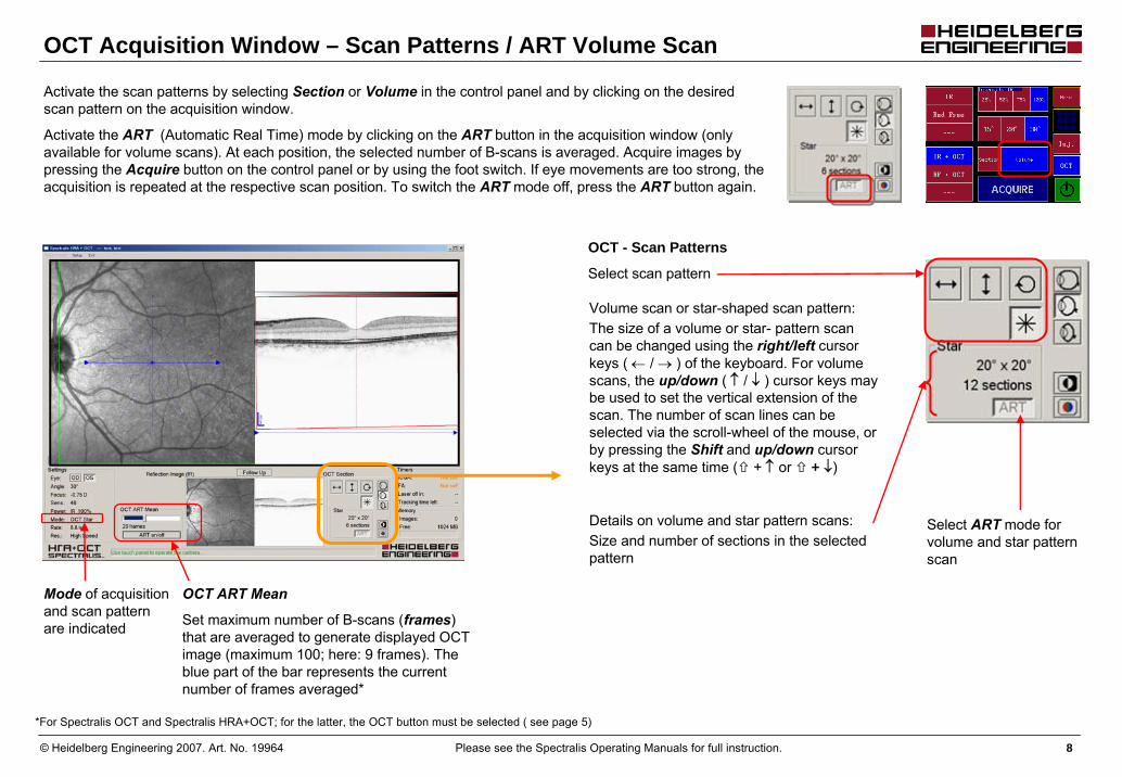
OCT Acquisition Window – Scan Patterns / ART Volume Scan
Mode of acquisition and scan pattern are indicated
OCT - Scan Patterns
Select scan pattern
Volume scan or star-shaped scan pattern:The size of a volume or star- pattern scan can be changed using the right/left cursor keys ( ← / → ) of the keyboard. For volume scans, the up/down ( ↑ / ↓ ) cursor keys may be used to set the vertical extension of the scan. The number of scan lines can be selected via the scroll-wheel of the mouse, or by pressing the Shift and up/down cursor keys at the same time ( + ↑ or + ↓)
*For Spectralis OCT and Spectralis HRA+OCT; for the latter, the OCT button must be selected ( see page 5)
Set maximum number of B-scans (frames) that are averaged to generate displayed OCT image (maximum 100; here: 9 frames). The blue part of the bar represents the current number of frames averaged*
OCT ART Mean
Select ART mode for volume and star pattern scan
Details on volume and star pattern scans:Size and number of sections in the selectedpattern
Activate the scan patterns by selecting Section or Volume in the control panel and by clicking on the desired scan pattern on the acquisition window.
Activate the ART (Automatic Real Time) mode by clicking on the ART button in the acquisition window (only available for volume scans). At each position, the selected number of B-scans is averaged. Acquire images by pressing the Acquire button on the control panel or by using the foot switch. If eye movements are too strong, the acquisition is repeated at the respective scan position. To switch the ART mode off, press the ART button again.

© Heidelberg Engineering 2007. Art. No. 19964 Please see the Spectralis Operating Manuals for full instruction. 9
Laser Scanning Acquisition Window
Menu barSave imagesSetup
Acquisition ParametersReset Injection TimerCalibration Touch Panel
Exit
Acquisition mode
Settings
Eye (OD-right, OS-left eye)Angle (field of view)FocusSensitivity:AUTO - automatic brightness control is enabledPower: Laser power (IR & ICGA)Mode of acquisitionRate: images per secondResolution: high speed or high resolution
Timers (for fluorescein / ICG angiography only)
Laser off in (remaining laser on time)
Memory
Images taken
Free memory available
Patient name, birth date
Minimize / maximize window
Tracking time left(for OCT only)
System Status LineGreen: informationYellow: warningRed: error message
*For Spectralis HRA and Spectralis HRA+OCT; for the latter, the OCT button must be deselected (see page 5)
Timer Log Window
Shows the injection timers of all patients imaged using angiography modes on the same day (unless the HEYEX was closed)

© Heidelberg Engineering 2007. Art. No. 19964 Please see the Spectralis Operating Manuals for full instruction. 10
Acquisition mode
Timers (for ICG / fluorescein angiography only)
Laser off in (remaining laser on time)
Tracking time left (for OCT only) Tracking time is limited to meet light exposure safety standards
System Status Line
Memory
Images taken
Free memory available
Laser Scanning ART COMPOSITE Acquisition Window
Red frame shows position of current live image in the composite image
Close window to end acquisition
Central area of live image in higher magnification to enable focusing
Live image to evaluate brightness and even illumination of image enables optimum camera adjustment
Activate ART Composite mode by selecting Composite in the control panel menu and pressing the sensitivity button of the control panel. Acquire images by pressing the Acquire button on the control panel or by using the foot switch. The ART mode remains switched on after an image or image series has been acquired. To switch the ART COMPOSITE mode off, press thesensitivity button again.
*If the live image cannot be matched, the last image stays on the screen and the position of the last live image is shown by a dotted frame. It is possible to acquire multiple images during the same ART Composite session by pressing the footswitch or the Acquire button on the control panel.*For Spectralis HRA and Spectralis HRA+OCT; for the latter, the OCT button must be deselected ( see page 5)
Composite image
Set number of images (frames) that are used for averaging (maximum 100) with the slider. The chosen value is indicated below the slider (here: 9 frames).
The blue part of the bar represents the current number of averaged frames processed*

© Heidelberg Engineering 2007. Art. No. 19964 Please see the Spectralis Operating Manuals for full instruction. 11
Red frame indicatesposition of current live image position
Mean (averaged) image
System Status Line
Set number of images (frames) that are used for averaging (maximum 100) with the slider. The chosen value is indicated below the slider.
The blue part of the bar represents the current number of averaged frames processed*
Activate ART Mean mode by pressing the sensitivity button of the control panel.
Acquisition mode
Timers (for ICG and fluorescein angiography only)
Laser off in (remaining laser on time)
Tracking time left (for OCT only) Tracking time is limited to meet light exposure safety standards
Memory
Images taken
Free memory available
* If the current live image cannot be aligned to the mean image for more than 1 second, the mean image will be discarded, the blue bar will disappear, and the automatic averaging process will start anew. The same happens when ART mode is deactivated and then again activated.
Central area of live image in higher magnification to enable focussing
Live image to evaluate brightness and even illumination of image enables optimum camera adjustment
Laser Scanning ART MEAN Acquisition Window
*For Spectralis HRA and Spectralis HRA+OCT; for the latter, the OCT button must be deselected ( see page 5)

© Heidelberg Engineering 2007. Art. No. 19964 Please see the Spectralis Operating Manuals for full instruction. 12
Move the camera so that the infrared live image is showing approximately the same area on the retina as the baseline image. As soon as the overlap between live and baseline image is sufficient, a green frame appears on the live image, indicating the area of the retina imaged during the baseline examination. Optimize the camera position for maximum overlap between live and baseline image. A blue line indicates the OCT scan position. The blue line and green box follow the eye movement. If there is too much eye movement and the live image can not be matched to the baseline image, the blue line will appear dotted.
To capture the follow-up image, press Acquire on the control panel. To cancel a follow-up acquisition, press on the Follow-up button again. A change of the scanning parameters (e.g. scan angle) will also automatically cancel the follow-up acquisition.
*For the Spectralis HRA+OCT, the OCT button must be selected ( see page 5)
For follow-up exams, the same fixation target chosen for the baseline exam is automatically activated.
The baseline exam will now be visible as a small image in the window below the live image.
OCT – Follow-up Acquisition Window
To be able to perform a follow-up acquisition, an image already stored in the HEYEX database must be defined as baseline or reference scan. To define a baseline image, right click on the image in the Patient File and select Progression, Set as reference. In the Patient File, the thumbnails of baseline images are marked with a special symbol in the bottom left corner. More than one baseline scan can be defined for every patient.
Spectralis OCT and HRA+OCT allow the repeat of an OCT scan at the exact same location that was selected during a previous exam.
If a baseline image exists for the current patient, a Follow-up button is available below the live image in the Acquisition window (thecamera must be in live mode). Pressing the Follow-up button will bring up a window with reference images. Click on the reference image a follow-up should be taken for and press OK.
2007/11/27 2007/11/27

© Heidelberg Engineering 2007. Art. No. 19964 Please see the Spectralis Operating Manuals for full instruction. 13
HEYEX – Image Viewing
Patient File
The image viewing window represents the digital Patient File. It contains all patient data and images. Each thumbnail represents an image or scanof the right or left eye. Images can be viewed, analyzed, printed, imported, exported and archived. All images from one acquisition session are stored under the same visit tab.
To open the Context Menu, click on the image icon with the right mouse button. Choose the desired menu item by selecting it with either the left or right mouse button.
From the patient file, patient data regarding diagnosis, referring physician, operator, eye data, etc. can be accessed via the buttons Patient, Examination and Eye Data.
Viewing Images
To open an image double-click on the image icon or select Display from the context menu. The selected image will be displayed in a separate window with its own menu and tool bar.
Context menu
Image icon
Patient data
Visit tab
Open images (from one or several patients) can be grouped or closed automatically. Use the Windowmenu with the options Cascade, Tileand Close All in the analysis window or in the Patient File.
The buttons shown on the right may be used to browse through images. When opening an image in the visit tab, all images of this eye and visit date will be displayed as image series using the black arrow buttons. If an image was opened via the Lightbox, all images in the Lightboxare used as image series.
Use the second set of buttons to step through consecutive follow-up examinations of a progression series.
When viewing an image series from the same acquisition date or from a progression series, the respective button (forward / backward) is deactivated once the last / first image of the image series is reached.
Extracting Single Images from Image Series
Single OCT images can be extracted from a volume or star pattern scan and saved individually. These single scans can then, for example, serve as baseline image for follow-up examinations.
From the Patient File, select a volume or star pattern scan (left mouse click), open the Context Menu (right mouse click) and select Expand. A new tab will open, displaying the single images from the scan series. This tab is marked with a yellow folder symbol. Select a single image and choose the option Extract Image from the Context Menuin order to save this OCT image separately.
To return to the Patient File, click on the yellow folder symbol.
From the Image menu in the analysis window, select the menu item Extract as Single Image (only available in the Display tab).

© Heidelberg Engineering 2007. Art. No. 19964 Please see the Spectralis Operating Manuals for full instruction. 14
Scales the image to the original resolution & size.
Display the previous / next image from the same examination date
Rotate view by 180°
Fit to window: Scales the image to fit into the actual window size
Draw Text: Insert text label
Draw Arrow: Draw arrow
Draw Region: Draw closed outline
Measure Distance
Measure Circle: Measure diameter (in mm) of drawn circle
Insert ETDRS-Grid: 4 concentric circles of 360, 600, 1800 and 3600 μm, 2 bisecting lines
The window size can be adjusted with the mouse
Add to lightbox: Insert link to the selected image/s intothe lightbox
Delete image (permanent)
Monitor Setup Tool
Info: Display image information
Menu
Image
Overlay
Zoom
Window
Overlay tools (these are automatically saved, but may be removed at any time)
Laser Scanning Image Analysis Window
Shortcut buttons (corresponding to Menu options)
Other tools

© Heidelberg Engineering 2007. Art. No. 19964 Please see the Spectralis Operating Manuals for full instruction. 15
Menu
Image
Progression
Options
HRA Image (left image)
OCT Image (right image)
Window
OCT Analysis – Display Window I
Viewing different OCT scans
The green highlighted line in the infrared image (left) shows the location of the current OCT scan (right image). The arrow indicates the direction of the OCT scan.
For volume scans, a green frame in the infrared image indicates the borders of the scanned area. If the scans in this area are less than 8 pixels apart from each other, only the active OCT scan is indicated. Choose a different scan from the series by left-mouse clicking within the green frame.
If the scans of a volume scan are less densely spaced, the inactive scans are indicated in dark green. Left-click on these lines to view the corresponding OCT scans.

© Heidelberg Engineering 2007. Art. No. 19964 Please see the Spectralis Operating Manuals for full instruction. 16
Click on the tabs to view the different analysis results:
Display (images taken during acquisition, this window)
3D View
Thickness Graph
Thickness Map
Add to Lightbox
Show next/previous image of same eye or from lightbox
Print Report
Brightness & Contrast (see previous page)
Green slider on the horizontal green line in infrared image corresponds to location of the green line in OCT image
OCT Analysis – Display Window II
Save as image
Y-Scale:
Show next/previous image in progression
The zoom factor represents the ratio of monitor pixels to image pixels.
If the Auto option is selected in the drop-down list, the image is automatically scaled to fit the window. In this case, if the window size is changed, the image is re-scaled.
If a fixed zoom factor is set (e.g. 100%), changing the size of the window will changethe image frame and not the scale. When the image is not shown in full size, scroll bars enable viewing of the full image and the button for the pan mode is active.
Image Info (see page 21)
Zoom functions:
Zoom Mode: Use left mouse button to zoom in or out
Zoom In
Zoom Out
Pan Mode: Move the enlarged image with the mouse
Unsmoothed Pixels(only if zoom >100%)
1:1 pixel: Shows all pixels acquired during the scan
1:1 µm: Shows a compressed view where the pixels are equally scaled horizontally and vertically
Play
Stop
Save the movie
Speed of movie
For volume or pattern scans:
Flicker betweenbaseline and follow-upimage
Speed of flicker
For follow-up images:Hot Keys:
Ctrl – Zoom InCtrl+Shift – Zoom OutShift – Pan

© Heidelberg Engineering 2007. Art. No. 19964 Please see the Spectralis Operating Manuals for full instruction. 17
Thickness Graph Tab
Green slider on the scan pattern in IR image corresponds to green line in OCT image (B-Scan)
Green highlighted pattern shows location of current OCT image (right image).
Thickness Profileof retina calculated from OCT B-Scan above
For follow-up examinations:Locations with retinal thickness changes compared to baseline are marked in red (increased retinal thickness) or green (decreased retinal thickness)
OCT B-Scan OCT pattern and location are indicated on the infrared image (scan corresponds to green pattern)
IR (Infrared) image
Linear Scans: thickness in µm
Circular scans: sectors and degrees
OCT Analysis – Thickness Graph Window
Legend for diagram
Scale for y-axis of diagram
Default setting: 1x (up to 4-fold)
Click on the arrows (up/down) to change scaling

© Heidelberg Engineering 2007. Art. No. 19964 Please see the Spectralis Operating Manuals for full instruction. 18
Thickness Map Tab
Overlay in IR imagewith current retinal thickness values
Single pixel position can be altered by drag and drop (left mouse button), pixel position is moved synchronously in all 4 images
Follow-up exam
Baseline exam
Difference / Change Map
OCT Analysis – Thickness Map Window
Thickness value of chosen single pixel position is displayed for all three images
Scale:
length of bar equals 200 μm
200 μm
200 μm
Thickness value at central locationof circle grid
Change the diameter of the circle grid (options: „1, 2, 3 mm“, „1, 2.22, 3.45 mm“ and „1, 3, 6 mm“)
Center the circle grid in the image
The position and size of the circle grid can be saved for each examination. For follow-up exams, the position of the circle grid is automatically takenfrom the baseline exam.
Reset cirle to the position last saved
Circle grid functions:
Transparency of overlay
Set range of thickness difference map down to +/- 50 μm(default range +/- 400 μm)
Zoom functions:
Zoom Mode: Use left mouse button to zoom in or out
Zoom In
Zoom Out
Pan Mode: Move the enlarged image with the mouse
Unsmoothed Pixels(only if zoom >100%)
Hot Keys:
Ctrl – Zoom InCtrl+Shift – Zoom OutShift – Pan

© Heidelberg Engineering 2007. Art. No. 19964 Please see the Spectralis Operating Manuals for full instruction. 19
3D View Tab
Display OptionsCube: Displays a volume scan as solid block
Surface: Removes the part of a volume scan above the ILM
Volume: (Not yet available)
Single: Displays volume or pattern scans as single slices
Show Grid: Shows a bounding box around the volume scan
Y-Scale: see p. 16
Reset View to standard display settings
T – Temporal
N – Nasal
I – Inferior
S – Superior
OCT Analysis – 3D View Window
Use the keyboard keys to view the image as indicated. Or, alternatively, use the mouse to view the 3D image:
► right mouse button: zoom
► left mouse button: rotate object
► mouse wheel: scroll through scans
Movie function for volume scans:
Star-pattern scan Circular scan
Single scan
Volume scanPlay
Stop
Save the movie
Speed of movie

© Heidelberg Engineering 2007. Art. No. 19964 Please see the Spectralis Operating Manuals for full instruction. 20
HEYEX – Monitor Setup Tool, Image Settings, General Settings
General Settings
In the caption line of the Analysis window, the image title is displayed in addition to patient name and acquisition date. If image numbers are activated via the menu option Setup / Options, this image number is also displayed.
Icons: On the left side of this tab, the icon size and spacing in the Patient File can be chosen.
Settings: Closing the window of the HEYEX will shut down the program. As standard setting, you will be asked to confirm that you wish to close the program. This confirmation window can be switched off.
Image Settings (Brightness & Contrast)
OCT Analysis Window
Open the control window by selecting theshortcut icon or the option Brightness & Contrast from the Image menu.
For the scanning laser image, brightnessand contrast can be adjusted together bymoving the black dot in the white square (up and down = brightness, left and right = contrast) or separately using the respectiveslider below the white square. For the OCT image, contrast can be adjusted using theslider. Both images can be shown in Grayscale (Black on White or White on Black) or Color. The Reset button resets all controls to standard values.
Image settings can also be adjusted bypressing the Alt-key and moving the mouseacross the respective image in the samefashion as in the control window.
Preferences
To turn off information "bubbles", open thePreferences dialog from the Options menu, and remove the checkmark for the optionDisplay info bubbles.
This tool offers a gray scale target for optimal monitor setup, which is especially important for LCD screens.
The Monitor Setup Tool window can either be opened via the shortcut button, or by choosing the respective option in the Image menu.
In order to optimize the monitor settings, follow the instructions in the Monitor Setup Tool window.
Monitor Setup Tool Laser Scanning Analysis Window
Open the control window by selecting theshortcut icon or the option Brightness & Contrast from the Image menu.
Brightness and Contrast can be adjustedtogether by moving the red dot in the greysquare (up and down = brightness, left and right = contrast) or separately using therespective edit field. The Reset button resetsall controls to standard values.

© Heidelberg Engineering 2007. Art. No. 19964 Please see the Spectralis Operating Manuals for full instruction. 21
HEYEX – Printing, Archiving, Software Versions, Image Information
Archiving
Archiving creates a copy of all of your data on a second mirrored FireWire drive. This protects your data from a hard drive crash.
In the Database menu of the database window, the function Archive Images starts the process to archive the data to an external media.
Printing
To print one or multiple scanning laser images to one page, select the desired images in the patient file and select Printfrom the context menu. Then select the Report type from the drop-down menu, and the number of images you wish to print on one page.
To print OCT scans, open the Analysiswindow and select the tab that contains theinformation to be printed.
Print the content of the currently displayedtab using the Print button or the menuoption Image / Print Report.
In order to insert a comment on the printout, click on the Examination button in the Patient File to open the Examination Datawindow and select the Diagnosis tab. Text entered in the Comment field will be automatically printed onto the report type Standard (Diagn. & Comment).
A screen print of the active window (topmost window displayed on the screen) can be obtained by holding down the CTRL and P key.
To check the versions of the Heidelberg Eye Explorer and the acquisition and viewing modules, please open the About box using the Help / About menu item in the database window.
Software Versions
The software release 3.1 includes the Spectralis Acquisition Module version 3.1, Spectralis Viewing Module 3.1 and Heidelberg Eye Explorer software version 1.5.12.
Image Information
Scan parameters of the scanning laser image are available in a separate window.
It is opened via the Info button or the menu option Image / Image Information.

© Heidelberg Engineering 2007. Art. No. 19964 Please see the Spectralis Operating Manuals for full instruction. 22
HEYEX – Image and Data Export
E2E File Export
To export images and other data in an examination including patient data as an E2E file, select the desired image icon(s) from the image viewing window, and select the item Export ► as E2E from the Context Menu in the Patient File. Viewing an E2E file requires HEYEX software for the respective module.
The Batch ► Export E2E feature in the database window enables export of multiple patient records at once.
Graphics File Export
Alternatively, images can be exported as graphics files. Use the Export ► as Picture option from the Context Menu or the menu item Export as picture in theImage menu of the Analysis window.1. Context Menu or Display: The
scanning laser and OCT images are displayed next to each other in full size, without further control elements. The y-scale of the OCT scan can be selected (1:1 pixel or 1:1 µm ), and it is possible to down-size the scanning laser image to the same height as the OCT image (512 x 512 pixels).
Additional Information
In addition to the image, the following information can be exported into the graphics file:
Patient – Name, ID, date of birth, ancestry
Examination – Date, OS/OD, image type, diagnosis
Image – Image type, time
In the Save as... window, select the optionAdd Info Block and choose the DisplayedPatient Info by ticking the respective boxed.
Save as
File Formats
Images can be exported in BMP, JPG, TIF or PNG format.
For export of images as TIF files, it is possible to select a compression method (None / LZW / Packbits). This reduces the size of the exported image file without loss of image information.
3. Thickness Graph: The displayed window is exported including the diagram.
4. Thickness Map: The displayed window is exported including the thickness map.
2. 3D View: The content of the 3D window is exported without control elements.
.
Graphics File Export (cont.)

© Heidelberg Engineering 2007. Art. No. 19964 Please see the Spectralis Operating Manuals for full instruction. 23
Corporate Headquarters Heidelberg Engineering GmbH • Tiergartenstr. 15 • 69121 Heidelberg • Germany
Phone +49 6221 6463-0 • Fax +49 6221 646362 • www.HeidelbergEngineering.de
US Main Office Heidelberg Engineering, Inc. • 1499 Poinsettia Avenue, Suite 160 • Vista, CA 92081
Phone 760 598-3770 • Fax 760 598-3060 • www.HeidelbergEngineering.com
US Service Center Heidelberg Engineering, Inc. • 410 Harris Road • Smithfield, RI 02917
Phone 401 349-0500 • Fax 401 349-0504 • www.HeidelbergEngineering.com