Embed Size (px)
Citation preview

Specifications Manual TECHTOWN Chilled Water System Upgrades PRB Duct System Modifications WSU Project Nos. 209-293924 & 209-313029
Issued for Bids PBA Project No. 2018.0434.00 January 2, 2019 5145 Livernois, Suite 100 Troy, MI 48098-3276 Tel: 248-879-5666 Fax: 248-879-0007

WAYNE STATE UNIVERSITY / TECHTOWN PETER BASSO ASSOCIATES, INC. Chilled Water System Upgrades PBA Project No. 2018.0434.00 PRB Duct System Modifications Issued for Bids WSU Project No. 209-293924 / 209-313029 January 2, 2019
TABLE OF CONTENTS TOC - 1
Division Section Title
SPECIFICATIONS GROUP
DIVISION 20 – COMMON MECHANICAL REQUIREMENTS
200500 MECHANICAL GENERAL REQUIREMENTS 200510 BASIC MECHANICAL MATERIALS AND METHODS 200513 MOTORS 200516 PIPE FLEXIBLE CONNECTORS, EXPANSION FITTINGS AND LOOPS 200519 METERS AND GAGES 200529 HANGERS AND SUPPORTS 200547 MECHANICAL VIBRATION CONTROLS 200553 MECHANICAL IDENTIFICATION 200700 MECHANICAL INSULATION 202923 VARIABLE FREQUENCY CONTROLLERS
DIVISION 23 - HEATING, VENTILATING, AND AIR CONDITIONING (HVAC)
230523 GENERAL-DUTY VALVES FOR HVAC 230593 TESTING, ADJUSTING, AND BALANCING 230933 TEMPERATURE CONTROLS 231123 FUEL GAS PIPING 232113 HYDRONIC PIPING 232123 HYDRONIC PUMPS 232510 PIPING SYSTEMS FLUSHING AND CHEMICAL CLEANING 232513 WATER TREATMENT FOR CLOSED-LOOP HYDRONIC SYSTEMS 233113 METAL DUCTS 233300 DUCT ACCESSORIES 233716 FABRIC AIR-DISTRIBUTION DEVICES 236423 SCROLL WATER CHILLERS
DIVISION 26 - ELECTRICAL
260010 ELECTRICAL GENERAL REQUIREMENTS 260519 CONDUCTORS AND CABLES 260526 GROUNDING AND BONDING 260529 HANGERS AND SUPPORTS FOR ELECTRICAL SYSTEMS 260533 RACEWAYS AND BOXES 260553 ELECTRICAL IDENTIFICATION 260573 OVERCURRENT DEVICE COORDINATION STUDY/ARC FLASH HAZARD ANALYSIS 260999 ELECTRICAL TESTING 262813 FUSES 262816 ENCLOSED SWITCHES AND CIRCUIT BREAKERS 262913 ENCLOSED CONTROLLERS 263213 PACKAGED ENGINE GENERATORS 263600 TRANSFER SWITCHES
END OF TABLE OF CONTENTS

WAYNE STATE UNIVERSITY / TECHTOWN PETER BASSO ASSOCIATES, INC. Chilled Water System Upgrades PBA Project No. 2018.0434.00 PRB Duct System Modifications Issued for Bids WSU Project No. 209-293924 / 209-313029 January 2, 2019
MECHANICAL GENERAL REQUIREMENTS 20 0500 - 1
SECTION 20 0500 - MECHANICAL GENERAL REQUIREMENTS
PART 1 - GENERAL ...................................................................................................................................................... 1
1.1 RELATED DOCUMENTS ............................................................................................................................. 1
1.2 SUMMARY .................................................................................................................................................... 1
1.3 INDUSTRY STANDARDS............................................................................................................................. 1
1.4 PERFORMANCE REQUIREMENTS ............................................................................................................ 2
1.5 QUALITY ASSURANCE ............................................................................................................................... 3
1.6 CODES, PERMITS AND FEES .................................................................................................................... 3
1.7 DRAWINGS .................................................................................................................................................. 3
1.8 MATERIAL AND EQUIPMENT MANUFACTURERS .................................................................................... 4
1.9 INSPECTION OF SITE ................................................................................................................................. 4
1.10 ITEMS REQUIRING PRIOR APPROVAL ..................................................................................................... 5
1.11 SUBMITTALS ............................................................................................................................................... 5
1.12 OPERATION AND MAINTENANCE INSTRUCTIONAL MANUALS ............................................................. 6
1.13 RECORD DRAWINGS .................................................................................................................................. 6
1.14 INSTRUCTION OF OWNER PERSONNEL .................................................................................................. 7
1.15 WARRANTY ................................................................................................................................................. 7
PART 2 - PRODUCTS ................................................................................................................................................... 7
PART 3 - EXECUTION .................................................................................................................................................. 7
3.1 MECHANICAL DEMOLITION WORK ........................................................................................................... 7
3.2 REFRIGERANT HANDLING ......................................................................................................................... 8
3.3 WORK IN EXISTING BUILDINGS ................................................................................................................ 8
3.4 TEMPORARY SERVICES ............................................................................................................................ 9
3.5 WORK INVOLVING OTHER TRADES ......................................................................................................... 9
3.6 ACCEPTANCE PROCEDURE ...................................................................................................................... 9
3.7 PROJECT COMMISSIONING ...................................................................................................................... 9
PART 1 - GENERAL
1.1 RELATED DOCUMENTS
A. Drawings and General Provisions of the Contract, including General and Supplementary Conditions and Division 01 Specification Sections, apply to work of this Section.
1.2 SUMMARY
A. This Section includes mechanical general administrative and procedural requirements. The following requirements are included in this Section to supplement the requirements specified in Division 01 Specification Sections.
1.3 INDUSTRY STANDARDS
A. Applicability of Standards: Unless the Contract Documents include more stringent requirements, applicable construction industry standards have the same force and effect as if bound or copied directly into the Contract Documents to the extent referenced. Such standards are made a part of the Contract Documents by reference.
1. AABC - Associated Air Balance Council; www.aabc.com. 2. AASHTO - American Association of State Highway and Transportation Officials;
www.transportation.org. 3. ABMA - American Bearing Manufacturers Association; www.americanbearings.org. 4. ABMA - American Boiler Manufacturers Association; www.abma.com.

WAYNE STATE UNIVERSITY / TECHTOWN PETER BASSO ASSOCIATES, INC. Chilled Water System Upgrades PBA Project No. 2018.0434.00 PRB Duct System Modifications Issued for Bids WSU Project No. 209-293924 / 209-313029 January 2, 2019
MECHANICAL GENERAL REQUIREMENTS 20 0500 - 2
5. AGA - American Gas Association; www.aga.org. 6. AHRI - Air-Conditioning, Heating, and Refrigeration Institute (The); www.ahrinet.org. 7. AMCA - Air Movement and Control Association International, Inc.; www.amca.org. 8. ANSI - American National Standards Institute; www.ansi.org. 9. ASHRAE - American Society of Heating, Refrigerating and Air-Conditioning Engineers;
www.ashrae.org. 10. ASME - ASME International; (American Society of Mechanical Engineers); www.asme.org. 11. ASSE - American Society of Sanitary Engineering; www.asse-plumbing.org. 12. ASTM - ASTM International; www.astm.org. 13. AWS - American Welding Society; www.aws.org. 14. AWWA - American Water Works Association; www.awwa.org. 15. CDA - Copper Development Association; www.copper.org. 16. CGA - Compressed Gas Association; www.cganet.com. 17. CISPI - Cast Iron Soil Pipe Institute; www.cispi.org. 18. CSA - CSA International; (Formerly: IAS - International Approval Services); www.csa-
international.org. 19. CSI - Construction Specifications Institute (The); www.csiresources.org. 20. CTI - Cooling Technology Institute; (Formerly: Cooling Tower Institute); www.cti.org. 21. FM Approvals - FM Approvals LLC; www.fmglobal.com. 22. HI - Hydraulic Institute; www.pumps.org. 23. ICC - International Code Council; www.iccsafe.org. 24. IEEE - Institute of Electrical and Electronics Engineers, Inc. (The); www.ieee.org. 25. IGSHPA - International Ground Source Heat Pump Association; www.igshpa.okstate.edu. 26. Intertek - Intertek Group; (Formerly: ETL SEMCO; Intertek Testing Service NA); www.intertek.com. 27. MSS - Manufacturers Standardization Society of The Valve and Fittings Industry Inc.; www.mss-
hq.org 28. NADCA - National Air Duct Cleaners Association; www.nadca.com. 29. NAIMA - North American Insulation Manufacturers Association; www.naima.org. 30. NEBB - National Environmental Balancing Bureau; www.nebb.org. 31. NECA - National Electrical Contractors Association; www.necanet.org. 32. NEMA - National Electrical Manufacturers Association; www.nema.org. 33. NETA - InterNational Electrical Testing Association; www.netaworld.org. 34. NFPA - National Fire Protection Association; www.nfpa.org. 35. NSF - NSF International; www.nsf.org. 36. NSPE - National Society of Professional Engineers; www.nspe.org. 37. SMACNA - Sheet Metal and Air Conditioning Contractors' National Association; www.smacna.org. 38. STI - Steel Tank Institute; www.steeltank.com. 39. TEMA - Tubular Exchanger Manufacturers Association, Inc.; www.tema.org. 40. UL - Underwriters Laboratories Inc.; www.ul.com. 41. USGBC - U.S. Green Building Council; www.usgbc.org.
B. Publication Dates: Comply with standards in effect as of date of the Contract Documents unless otherwise indicated.
C. Copies of Standards: Each entity engaged in construction on Project should be familiar with industry standards applicable to its construction activity. Copies of applicable standards are not bound with the Contract Documents.
1. Where copies of standards are needed to perform a required construction activity, obtain copies directly from publication source.
1.4 PERFORMANCE REQUIREMENTS
A. Systems Components Pressure and Temperature Ratings: Not less than indicated and as required for system pressures and temperatures.
WAYNE STATE UNIVERSITY / TECHTOWN PETER BASSO ASSOCIATES, INC. Chilled Water System Upgrades PBA Project No. 2018.0434.00 PRB Duct System Modifications Issued for Bids WSU Project No. 209-293924 / 209-313029 January 2, 2019
MECHANICAL GENERAL REQUIREMENTS 20 0500 - 3
1.5 QUALITY ASSURANCE
A. Scope of Work: Furnish all labor, material, equipment, technical supervision, and incidental services required to complete, test and leave ready for operation the mechanical systems as specified and as indicated on Drawings.
1. Contract Documents are complimentary, and what is required by one shall be as binding as if required by all. In the event of inconsistencies or disagreements within the Construction Documents bids shall be based on the most expensive combination of quality and quantity of the work indicated.
B. Ordinances and Codes: Perform all Work in accordance with applicable Federal, State and local ordinances and regulations, the Rules and Regulations of ASHRAE, NFPA, SMACNA and UL, unless otherwise indicated.
1. Notify the Architect/Engineer in writing before submitting a proposal should any changes in Drawings or Specifications be required to conform to the above codes, rules or regulations.
2. If the Contractor performs any work knowing it to be contrary to such laws, ordinances, rules and regulations, and without notice to A/E, the Contractor shall bear all costs arising from corrective measures.
C. Source Limitations: Obtain equipment and other components of the same or similar systems through one source from a single manufacturer.
D. Tests and Inspections: Perform all tests required by state, city, county and/or other agencies having jurisdiction. Provide all materials, equipment, etc., and labor required for tests.
E. Performance Requirements: Perform all work in a first class and workmanlike manner, in accordance with the latest accepted standards and practices for the trades involved.
F. Sequence and Schedule: Perform work to avoid interference with the work of other trades. Remove and relocate work which in the opinion of the Owner’s Representatives causes interference.
G. Labeling Requirement for Packaged Equipment: Electrical panels on packaged mechanical equipment shall bear UL label or label of other Nationally Recognized Testing Laboratory (NRTL) (Intertek, CSA, etc.).
1.6 CODES, PERMITS AND FEES
A. Unless otherwise indicated, all required permits, licenses, inspections, approvals and fees for Mechanical Work shall be secured and paid for by the Contractor. All Work shall conform to all applicable codes, rules and regulations.
B. Rules of local utility companies shall be complied with. Check with each utility company supplying service to the installation and determine all devices including, but not limited to, all valves, meter boxes, and meters which will be required and include the cost of all such items in proposal.
C. All work shall be executed in accordance with the rules and regulations set forth in local and state codes. Prepare any detailed drawings or diagrams which may be required by the governing authorities. Where the drawings and/or specifications indicate materials or construction in excess of code requirements, the drawings and/or specifications shall govern.
1.7 DRAWINGS
A. The drawings show the location and general arrangement of equipment, piping and related items. They shall be followed as closely as elements of the construction will permit.
WAYNE STATE UNIVERSITY / TECHTOWN PETER BASSO ASSOCIATES, INC. Chilled Water System Upgrades PBA Project No. 2018.0434.00 PRB Duct System Modifications Issued for Bids WSU Project No. 209-293924 / 209-313029 January 2, 2019
MECHANICAL GENERAL REQUIREMENTS 20 0500 - 4
B. Examine the drawings of other trades and verify the conditions governing the work on the job site. Arrange work accordingly. Provide fittings, valves, and accessories as required to meet actual conditions.
C. Deviations from the drawings, with the exception of minor changes in routing and other such incidental changes that do not affect the functioning or serviceability of the systems, shall not be made without the written approval of the Architect/Engineer.
D. The Architectural and Structural Drawings take precedence in all matters pertaining to the building structure, Mechanical Drawings in all matters pertaining to Mechanical Trades and Electrical Drawings in all matters pertaining to Electrical Trades. Where there are conflicts or differences between the drawings for the various trades, report such conflicts or differences to the Architect/Engineer for resolution.
E. Drawings are not intended to be scaled for rough-in or to serve as shop drawings. Take all field measurements required to complete the Work.
1.8 MATERIAL AND EQUIPMENT MANUFACTURERS
A. Equipment: All items of equipment shall be furnished complete with all accessories normally supplied with the catalog items listed and all other accessories necessary for a complete and satisfactory operating system. All equipment and materials shall be new and shall be standard products of manufacturers regularly engaged in the production of plumbing, heating, ventilating and air conditioning equipment and shall be the manufacturer's latest design.
B. If an approved manufacturer is other than the manufacturer used as the basis for design, the equipment or product provided shall be equal in size, quality, durability, appearance, capacity, and efficiency through all ranges of operation, shall conform with arrangements and space limitations of the equipment shown on the plans and/or specified, shall be compatible with the other components of the system and shall comply with the requirements for Items Requiring Prior Approval specified in this section of the Specifications. All costs to make these items of equipment comply with these requirements including, but not limited to, piping, sheet metal, electrical work, and building alterations shall be included in the original Bid.
C. All package unit equipment and skid mounted mechanical components that are factory assembled shall meet, in detail, the products named and specified within each section of the Mechanical and Electrical Specifications.
D. Changes Involving Electrical Work: The design of the mechanical systems is based on the equipment scheduled on the Drawings. Equipment of higher electrical characteristics may be furnished provided such proposed equipment is approved in writing and connecting electrical services, circuit breakers, and conduit sizes are appropriately modified with no additional cost to project. If minimum energy ratings or efficiencies are specified, equipment shall comply with requirements.
1. Where equipment changes are made that involve additional Electrical Work (larger size motor, additional wiring of equipment, etc.) the Mechanical Trades involved shall compensate the Electrical Trades for the cost of the additional Work required.
1.9 INSPECTION OF SITE
A. Visit the site, examine and verify the conditions under which the Work must be conducted before submitting Proposal. The submitting of a Proposal implies that the Contractor has visited the site and understands the conditions under which the Work must be conducted. No additional charges will be allowed because of failure to make this examination or to include all materials and labor to complete the Work.
B. No contract sum adjustments or contract time extensions will be made for Contractor claims arising from conditions which were or could have been observable, ascertainable or reasonably foreseeable from a site visit or inquiry into local conditions affecting the execution of the work.

WAYNE STATE UNIVERSITY / TECHTOWN PETER BASSO ASSOCIATES, INC. Chilled Water System Upgrades PBA Project No. 2018.0434.00 PRB Duct System Modifications Issued for Bids WSU Project No. 209-293924 / 209-313029 January 2, 2019
MECHANICAL GENERAL REQUIREMENTS 20 0500 - 5
1.10 ITEMS REQUIRING PRIOR APPROVAL
A. Bids shall be based upon manufactured equipment specified. All items that the Contractor proposes to use in the Work that are not specifically named in the Contract Documents must be submitted for review prior to bids. Such items must be submitted in compliance with Division 01 specifications. Requests for prior approval must be accompanied by complete catalog information, including but not limited to, model, size, accessories, complete electrical information and performance data in the form given in the equipment schedule on the drawings at stated design conditions. Where items are referred to by symbolic designations on the drawings, all requests for prior approval shall bear the same designations.
1. Equipment to be considered for prior approval shall be equal in quality, durability, appearance, capacity and efficiency through all ranges of operation, shall fulfill the requirements of equipment arrangement and space limitations of the equipment shown on the plans and/or specified and shall be compatible with the other components of the system.
2. All costs incurred to make equipment comply with other requirements, including providing maintenance, clearance, piping, sheet metal, electrical, replacement of other components, and building alterations shall be included in the original bid.
B. Voluntary alternates may be submitted for consideration, with listed addition or deduction to the bid, but will not affect the awarding of the contract.
1.11 SUBMITTALS
A. Submit project specific submittals for review in compliance with Division 01.
B. Prepare shop drawings to scale for the Architect/Engineer for review. Equipment and material submittals required are indicated in the Mechanical; Fire Suppression; Plumbing; and Heating, Ventilating and Air Conditioning Sections. Refer to Division 01 for submittal quantities.
C. All submittals shall be submitted in groupings of similar and/or related items. Plumbing fixture submittals shall be submitted as one package including all fixtures intended to be used for this project. Incomplete submittal groupings will be returned “Rejected”. Submit shop drawing with identification mark number or symbol numbers as specified or scheduled on the Mechanical Drawings.
D. All submittals shall be project specific. Standard detail drawings and schedule not clearly indicating which data is associated with this Project will be returned “Rejected”.
E. Shop drawings shall be reviewed by the Mechanical Contractor for completeness and accuracy prior to submitting to the Architect/Engineer for review. The shop drawings shall be dated and signed by the Mechanical Contractor prior to submission.
F. No equipment shall be shipped from stock or fabricated until shop drawings for them have been reviewed by the Architect/Engineer. Review is only for general conformance with the design concept of the project and general compliance with the information given in the Contract Documents. Any action indicated is subject to the requirement of the plans and specifications.
1. By the review of shop drawings, the Architect/Engineer does not assume responsibility for actual dimensions or for the fit of completed work in position, nor does such review relieve Mechanical Trades of full responsibility for the proper and correct execution of the work required.
2. Contractor is responsible for:
a. Dimensions, which shall be confirmed and correlated at the job site. b. Fabrication processes and techniques of construction. c. Quantities. d. Coordination of Contractor’s work with all other trades. e. Satisfactory performance of Contractor’s work. f. Temporary aspects of the construction process.

WAYNE STATE UNIVERSITY / TECHTOWN PETER BASSO ASSOCIATES, INC. Chilled Water System Upgrades PBA Project No. 2018.0434.00 PRB Duct System Modifications Issued for Bids WSU Project No. 209-293924 / 209-313029 January 2, 2019
MECHANICAL GENERAL REQUIREMENTS 20 0500 - 6
G. Submit detailed shop drawings of piping systems showing pipe routing and types and locations of all pipe hangers/supports.
H. If deviations (not substitutions) from Contract Documents are deemed necessary by the Contractor, details of such deviations, including changes in related portions of the project and the reasons therefore, shall be submitted with the submittal for approval.
1.12 OPERATION AND MAINTENANCE INSTRUCTIONAL MANUALS
A. Submit project specific Operation and Maintenance Instructional Manuals for review in compliance with Division 01 Specification Sections.
B. Provide complete operation and maintenance instructional manuals covering all mechanical equipment herein specified, together with parts lists. Maintenance and operating instructional manuals shall be job specific to this project. Generic manuals are not acceptable. One copy of all manuals shall be furnished for Owner. Maintenance and operating instructional manuals shall be provided when construction is approximately 75 percent complete.
C. Format: Submit operations and maintenance manuals in the following format:
1. PDF electronic file. Assemble each manual into a composite electronically indexed file. Submit on digital media acceptable to Architect.
a. Name each indexed document file in composite electronic index with applicable item name. Include a complete electronically linked operation and maintenance directory.
b. Enable inserted reviewer comments on draft submittals.
D. Operation and maintenance instructional manuals shall be submitted a minimum of four (4) weeks prior to functional testing.
E. The operating and maintenance instructions shall include a brief, general description for all mechanical systems including, but not limited to:
1. Routine maintenance procedures. 2. Lubrication chart listing all types of lubricants to be used for each piece of equipment and the
recommended frequency of lubrication. 3. Trouble-shooting procedures. 4. Contractor's telephone numbers for warranty repair service. 5. Submittals. 6. Recommended spare parts list. 7. Names and telephone numbers of major material suppliers and subcontractors. 8. System schematic drawings.
1.13 RECORD DRAWINGS
A. Submit record drawings in compliance with Division 01.
B. Contractor shall submit to the Architect/Engineer, record drawings on electronic media or vellum which have been neatly marked to represent as-built conditions for all new mechanical work.
C. The Contractor shall keep accurate note of all deviations from the construction documents and discrepancies in the underground concealed conditions and other items of construction on field drawings as they occur. The marked up field documents shall be available for review by the Architect, Engineer and Owner at their request.
WAYNE STATE UNIVERSITY / TECHTOWN PETER BASSO ASSOCIATES, INC. Chilled Water System Upgrades PBA Project No. 2018.0434.00 PRB Duct System Modifications Issued for Bids WSU Project No. 209-293924 / 209-313029 January 2, 2019
MECHANICAL GENERAL REQUIREMENTS 20 0500 - 7
1.14 INSTRUCTION OF OWNER PERSONNEL
A. Before final inspection, instruct Owner's designated personnel in operation, adjustment, and maintenance of mechanical equipment and systems at agreed upon times. A minimum of 24 hours of formal instruction to Owner's personnel shall be provided. Additional hours are specified in individual specification sections.
B. For equipment requiring seasonal operation, perform instructions for other seasons within six months.
C. Use operation and maintenance manuals as basis for instruction. Review contents of manual with personnel in detail to explain all aspects of operation and maintenance.
D. In addition to individual equipment training provide overview of each mechanical system. Utilize the as-built documents for this overview.
E. Prepare and insert additional data in operation and maintenance manual when need for such data becomes apparent during instruction.
1.15 WARRANTY
A. Warranty: Comply with the requirements in Division 01 Specification Sections. Contractor shall warranty that the mechanical installation is free from defects and agrees to replace or repair, to the Owner’s satisfaction, any part of this mechanical installation which becomes defective within a period of one year (unless specified otherwise in other Mechanical; Fire Suppression; Plumbing; or Heating, Ventilating and Air Conditioning Sections) from the date of substantial completion following final acceptance, provided that such failure is due to defects in the equipment, material, workmanship or failure to follow the contract documents.
B. File with the Owner any and all warranties from the equipment manufacturers including the operating conditions and performance capacities they are based on.
PART 2 - PRODUCTS
Not Applicable
PART 3 - EXECUTION
3.1 MECHANICAL DEMOLITION WORK
A. Demolition of existing mechanical equipment and materials shall be done by the Contractor unless otherwise indicated. Include items such as, but not limited to, existing piping, pumps, ductwork, supports, and equipment where such items are not required for the proper operation of the modified system.
B. Include draining of piping systems where required for demolition, modification of, or connection to existing systems.
C. In general, demolition work is indicated on the Drawings. However, the Contractor shall visit the job site to determine the full extent and character of this Work.
D. Unless specifically noted to the contrary, removed materials shall not be reused in the work. Salvaged materials that are to be reused shall be stored safe against damage and turned over to the appropriate trade for reuse.

WAYNE STATE UNIVERSITY / TECHTOWN PETER BASSO ASSOCIATES, INC. Chilled Water System Upgrades PBA Project No. 2018.0434.00 PRB Duct System Modifications Issued for Bids WSU Project No. 209-293924 / 209-313029 January 2, 2019
MECHANICAL GENERAL REQUIREMENTS 20 0500 - 8
1. Salvaged materials of value that are not to be reused shall remain the property of the Owner unless such ownership is waived.
2. Remove items from the systems and turn over to the Owner in their condition prior to removal. The Owner will move and store these materials.
3. Items on which the Owner waives ownership shall become the property of the Contractor, who shall remove and legally dispose of same, away from the premises.
E. Work that has been cut or partially removed shall be protected against damage until covered by permanent construction.
F. Where existing equipment is to be removed, cap piping under floor, behind face of wall, above ceiling, or at mains.
G. Cap ductwork and cap piping immediately adjacent to demolition as soon as demolition commences in order to allow existing systems to remain in operation.
1. Cap or plug piping with same or compatible piping material. 2. Cap or plug ducts with same or compatible ductwork material.
3.2 REFRIGERANT HANDLING
A. Refrigerant contained in the existing chillers is to be removed and retained by the Owner.
B. Refrigerant handling made necessary by the new chillers shall be the responsibility of the Contractor.
C. Refrigerant Installation and Disposal: Perform all work related to refrigerant contained in chillers, cooling coils, air conditioners, and similar equipment, including related piping, in strict accordance with the following requirements:
1. ASHRAE Standard 15 and Related Revisions: Safety Code for Mechanical Refrigeration. 2. ASHRAE Standard 34 and Related Revisions: Number Designation and Safety Classification of
Refrigerants. 3. United States Environmental Protection Agency (US EPA) requirements of Section 8 08
(Prohibition of Venting and Regulation of CFC) and applicable State and Local regulations of authorities having jurisdiction.
D. Recovered refrigerant is the property of the Contractor. Dispose of refrigerant legally, in accordance with applicable rules and regulations.
3.3 WORK IN EXISTING BUILDINGS
A. The Owner will provide access to existing buildings as required. Access requirements to occupied buildings shall be identified on the project schedule. The Contractor, once Work is started in the existing building, shall complete same without interruption so as to return work areas as soon as possible to Owner.
B. Adequately protect and preserve all existing and newly installed Work. Promptly repair any damage to same at Contractor's expense.
C. Consult with the Owner’s Representative as to the methods of carrying on the Work so as not to interfere with the Owner's operation any more than absolutely necessary. Accordingly, all service lines shall be kept in operation as long as possible and the services shall only be interrupted at such time as will be designated by the Owner's Representative.
D. Prior to starting work in any area, obtain approval for doing so from a qualified representative of the Owner who is designated and authorized by the Owner to perform testing and abatement, if necessary, of all

WAYNE STATE UNIVERSITY / TECHTOWN PETER BASSO ASSOCIATES, INC. Chilled Water System Upgrades PBA Project No. 2018.0434.00 PRB Duct System Modifications Issued for Bids WSU Project No. 209-293924 / 209-313029 January 2, 2019
MECHANICAL GENERAL REQUIREMENTS 20 0500 - 9
hazardous materials including but not limited to, asbestos. The Contractor shall not perform any inspection, testing, containment, removal or other work that is related in any way whatsoever to hazardous materials under the Contract.
3.4 TEMPORARY SERVICES
A. The existing building will be occupied during construction. Maintain mechanical services and provide necessary temporary connections and their removal at no additional cost to the Owner.
3.5 WORK INVOLVING OTHER TRADES
A. Certain items of equipment or materials specified in the Mechanical Division may have to be installed by other trades due to code requirements or union jurisdictional requirements. In such instances, the Contractor shall complete the work through an approved, qualified subcontractor and shall include the full cost for same in proposal.
3.6 ACCEPTANCE PROCEDURE
A. Upon successful completion of start-up and recalibration, but prior to building acceptance, substantial completion and commencement of warranties, the Architect/Engineer shall be requested in writing to observe the satisfactory operation of all mechanical control systems.
B. The Contractor shall demonstrate operation of equipment and control systems, including each individual component, to the Owner and Architect/Engineer.
C. After correcting all items appearing on the punch list, make a second written request to the Owner and Architect/Engineer for observation and approval.
D. After all items on the punch list are corrected and formal approval of the mechanical systems is provided by the Architect/Engineer, the Contractor shall indicate to the Owner in writing the commencement of the warranty period.
E. Operation of the following systems shall be demonstrated:
1. Air Handling Systems. 2. Chilled Water Systems. 3. Temperature Controls.
F. For systems requiring seasonal operation, demonstrate system performance within six months when weather conditions are suitable.
3.7 PROJECT COMMISSIONING
A. Refer to Division 01 “Project Commissioning” and the Commissioning Manual.
B. Purpose: Training, documentation and verification of the operation and functional performance of mechanical systems for compliance with the “design intent.”
END OF SECTION 20 0500

WAYNE STATE UNIVERSITY / TECHTOWN PETER BASSO ASSOCIATES, INC. Chilled Water System Upgrades PBA Project No. 2018.0434.00 PRB Duct System Modifications Issued for Bids WSU Project No. 209-293924 / 209-313029 January 2, 2019
BASIC MECHANICAL MATERIALS AND METHODS 20 0510 - 1
SECTION 20 0510 - BASIC MECHANICAL MATERIALS AND METHODS
PART 1 - GENERAL ...................................................................................................................................................... 1
1.1 RELATED DOCUMENTS ............................................................................................................................. 1
1.2 SUMMARY .................................................................................................................................................... 2
1.3 DEFINITIONS ............................................................................................................................................... 2
1.4 SUBMITTALS ............................................................................................................................................... 2
1.5 QUALITY ASSURANCE ............................................................................................................................... 3
1.6 DELIVERY, STORAGE, AND HANDLING .................................................................................................... 3
1.7 COORDINATION .......................................................................................................................................... 3
PART 2 - PRODUCTS ................................................................................................................................................... 4
2.1 MANUFACTURERS ..................................................................................................................................... 4
2.2 PIPE, TUBE, AND FITTINGS ....................................................................................................................... 4
2.3 JOINING MATERIALS .................................................................................................................................. 4
2.4 PIPE THREAD COMPOUNDS ..................................................................................................................... 5
2.5 DIELECTRIC FITTINGS ............................................................................................................................... 5
2.6 SLEEVES...................................................................................................................................................... 6
2.7 ESCUTCHEONS .......................................................................................................................................... 6
2.8 GROUT ......................................................................................................................................................... 6
2.9 EPOXY BONDING COMPOUND .................................................................................................................. 7
2.10 LEAK DETECTOR SOLUTION ..................................................................................................................... 7
2.11 PIPE ROOF PENETRATION ENCLOSURES .............................................................................................. 7
PART 3 - EXECUTION .................................................................................................................................................. 7
3.1 PIPING SYSTEMS - COMMON REQUIREMENTS ...................................................................................... 7
3.2 PIPING JOINT CONSTRUCTION ............................................................................................................... 10
3.3 EQUIPMENT CONNECTIONS ................................................................................................................... 12
3.4 PIPING CONNECTIONS ............................................................................................................................ 12
3.5 EQUIPMENT INSTALLATION - COMMON REQUIREMENTS ................................................................... 12
3.6 PAINTING ................................................................................................................................................... 12
3.7 CONCRETE BASES ................................................................................................................................... 13
3.8 ERECTION OF METAL SUPPORTS AND ANCHORAGES ....................................................................... 13
3.9 EPOXY BONDING TO EXISTING MATERIALS ......................................................................................... 13
3.10 JACKING OF PIPE ..................................................................................................................................... 13
3.11 GROUTING ................................................................................................................................................. 13
3.12 CUTTING, CORING AND PATCHING ........................................................................................................ 14
3.13 FLASHING .................................................................................................................................................. 14
3.14 LUBRICATION ............................................................................................................................................ 14
3.15 FILTERS ..................................................................................................................................................... 14
3.16 CLEANING .................................................................................................................................................. 14
PART 1 - GENERAL
1.1 RELATED DOCUMENTS
A. Drawings and general provisions of the Contract, including General and Supplementary Conditions and Division 01 Specification Sections, apply to this Section.
B. Related Sections include the following:
1. Division 20 Section “Mechanical General Requirements.” 2. Division 23 Section “Piping Systems Flushing and Chemical Cleaning” for flushing and cleaning of
HVAC piping.

WAYNE STATE UNIVERSITY / TECHTOWN PETER BASSO ASSOCIATES, INC. Chilled Water System Upgrades PBA Project No. 2018.0434.00 PRB Duct System Modifications Issued for Bids WSU Project No. 209-293924 / 209-313029 January 2, 2019
BASIC MECHANICAL MATERIALS AND METHODS 20 0510 - 2
1.2 SUMMARY
A. This section includes mechanical materials and installation methods common to mechanical piping systems, sheet metal systems and equipment. This section supplements all other Division 20, 21, 22, and 23 Mechanical Sections, and Division 01 Specification Sections.
1.3 DEFINITIONS
A. Finished Spaces: Spaces other than mechanical and electrical equipment rooms, furred spaces, pipe and duct shafts, unheated spaces immediately below roof, spaces above ceilings, unexcavated spaces, crawlspaces, and tunnels.
B. Exposed, Interior Installations: Exposed to view indoors. Examples include finished occupied spaces and mechanical equipment rooms.
C. Exposed, Exterior Installations: Exposed to view outdoors or subject to outdoor ambient temperatures and weather conditions. Examples include rooftop locations.
D. Concealed, Interior Installations: Concealed from view and protected from physical contact by building occupants. Examples include above ceilings and in duct shafts.
E. Concealed, Exterior Installations: Concealed from view and protected from weather conditions and physical contact by building occupants but subject to outdoor ambient temperatures. Examples include installations within unheated shelters.
F. The following are industry abbreviations for plastic materials:
1. ABS: Acrylonitrile-butadiene-styrene plastic. 2. CPVC: Chlorinated polyvinyl chloride plastic. 3. PE: Polyethylene plastic. 4. PVC: Polyvinyl chloride plastic. 5. RTRF: Reinforced thermosetting resin (fiberglass) fittings. 6. RTRP: Reinforced thermosetting resin (fiberglass) pipe.
G. The following are industry abbreviations for rubber materials:
1. EPDM: Ethylene-propylene-diene terpolymer rubber. 2. NBR: Acrylonitrile-butadiene rubber.
1.4 SUBMITTALS
A. Product Data: For the following:
1. Transition fittings. 2. Dielectric fittings. 3. Mechanical sleeve seals. 4. Escutcheons.
B. Welding certificates.
C. Brazing Certificates: As required by ASME Boiler and Pressure Vessel Code, Section IX, or AWS B2.2.
WAYNE STATE UNIVERSITY / TECHTOWN PETER BASSO ASSOCIATES, INC. Chilled Water System Upgrades PBA Project No. 2018.0434.00 PRB Duct System Modifications Issued for Bids WSU Project No. 209-293924 / 209-313029 January 2, 2019
BASIC MECHANICAL MATERIALS AND METHODS 20 0510 - 3
1.5 QUALITY ASSURANCE
A. Regulatory Requirements: Comply with requirements in Public Law 111-380, "Reduction of Lead in Drinking Water Act," about lead content in materials that will be in contact with potable water for human consumption.
B. Steel Support Welding: Qualify processes and operators according to AWS D1.1, "Structural Welding Code--Steel."
C. Steel Pipe Welding: Qualify processes and operators according to ASME Boiler and Pressure Vessel Code: Section IX, "Welding and Brazing Qualifications."
1. Comply with provisions in ASME B31 Series, "Code for Pressure Piping." 2. Certify that each welder has passed AWS qualification tests for welding processes involved and
that certification is current.
D. Brazing: Qualify processes and operators according to ASME Boiler and Pressure Vessel Code: Section IX, "Welding and Brazing Qualifications," or AWS B2.2, "Standard for Brazing Procedure and Performance Qualification."
E. Soldering: Qualify processes and operators according to AWS B2.3/2.3M, "Specification for Soldering Procedure and Performance Qualification."
F. Installer Qualifications:
1. Installers of Grooved Components: Installers shall be certified by the grooved component manufacturer as having been trained and qualified to join piping with grooved couplings, fittings, and specialties.
1.6 DELIVERY, STORAGE, AND HANDLING
A. Storage and Protection: Provide adequate weather protected storage space for all mechanical equipment and materials deliveries to the job site. Storage locations will be designated by the Owner’s Representative. Equipment stored in unprotected areas must be provided with temporary protection.
1. Protect equipment and materials from theft, injury or damage. 2. Protect equipment outlets, pipe and duct openings with temporary plugs or caps. 3. Materials with enamel or glaze surface shall be protected from damage by covering and/or coating
as recommended in bulletin “Handling and Care of Enameled Cast Iron Plumbing Fixtures”, issued by the Plumbing Fixtures Manufacturer Association, and as approved.
4. Electrical equipment furnished by Mechanical Trades and installed by the Electrical Trades: Turn over to Electrical Trades in good condition, receive written confirmation of same.
5. Deliver pipes and tubes with factory-applied end caps. Maintain end caps through shipping, storage, and handling to prevent pipe end damage and to prevent entrance of dirt, debris, and moisture.
6. Store plastic pipes protected from direct sunlight. Support to prevent sagging and bending.
1.7 COORDINATION
A. Arrange for pipe spaces, chases, slots, and openings in building structure during progress of construction, to allow for mechanical installations. Coordinate with other trades to ensure accurate locations and sizes of mechanical spaces, chases, slots, shafts, recesses and openings.
B. The mechanical trades shall be responsible for all damage to other work caused by their work or through the neglect of their workers.
WAYNE STATE UNIVERSITY / TECHTOWN PETER BASSO ASSOCIATES, INC. Chilled Water System Upgrades PBA Project No. 2018.0434.00 PRB Duct System Modifications Issued for Bids WSU Project No. 209-293924 / 209-313029 January 2, 2019
BASIC MECHANICAL MATERIALS AND METHODS 20 0510 - 4
1. All patching and repair of any such damaged work shall be performed by the trades which installed the work. The cost shall be paid by the Mechanical Trades.
PART 2 - PRODUCTS
2.1 MANUFACTURERS
A. In other Part 2 articles where subparagraph titles below introduce lists, the following requirements apply for product selection:
1. Manufacturers: Subject to compliance with requirements, provide products by the manufacturers specified.
2.2 PIPE, TUBE, AND FITTINGS
A. Refer to individual Division 21, 22, and 23 piping Sections for pipe, tube, and fitting materials and joining methods.
B. Pipe Threads: ASME B1.20.1 for factory-threaded pipe and pipe fittings.
2.3 JOINING MATERIALS
A. Refer to individual Division 21, 22, and 23 piping Sections for special joining materials not listed below.
B. Unions: Pipe Size 2 Inches and Smaller:
1. Ferrous pipe: Malleable iron ground joint type unions. 2. Unions in galvanized piping system shall be galvanized. 3. Copper tube and pipe: Bronze unions with soldered joints.
C. Flanges: Pipe Sizes 2-1/2 Inch and Larger:
1. Ferrous pipe: Standard weight, forged steel weld neck flanges. 2. Copper tube and pipe: Slip-on bronze flanges.
D. Pipe-Flange Gasket Materials: Suitable for chemical and thermal conditions of piping system contents.
1. ASME B16.21, nonmetallic, flat, asbestos-free, 1/8-inch maximum thickness unless thickness or specific material is indicated.
a. Full-Face Type: For flat-face, Class 125, cast-iron and cast-bronze flanges. b. Narrow-Face Type: For raised-face, Class 250, cast-iron and steel flanges.
2. AWWA C110, rubber, flat face, 1/8 inch thick, unless otherwise indicated; and full-face or ring type, unless otherwise indicated.
E. Flange Bolts and Nuts: ASME B18.2.1, carbon steel, unless otherwise indicated. Square head bolts and nuts are not acceptable.
F. Solder Filler Metals: ASTM B 32, lead-free, antimony-free, silver-bearing alloys. Include water-flushable flux according to ASTM B 813.
G. Brazing Filler Metals: Alloys meeting AWS A5.8.

WAYNE STATE UNIVERSITY / TECHTOWN PETER BASSO ASSOCIATES, INC. Chilled Water System Upgrades PBA Project No. 2018.0434.00 PRB Duct System Modifications Issued for Bids WSU Project No. 209-293924 / 209-313029 January 2, 2019
BASIC MECHANICAL MATERIALS AND METHODS 20 0510 - 5
1. Use Type BcuP Series, silver-bearing, copper-phosphorus alloys for joining copper or bronze socket fittings with copper pipe. Flux is prohibited unless used with bronze fittings.
2. Use Type Bag Series, cadmium-free silver alloys for joining copper with steel, stainless steel, or other ferrous alloys.
H. Welding Filler Metals: Comply with AWS D10.12/D10.12M for welding materials appropriate for wall thickness and chemical analysis of steel pipe being welded.
I. Welding Materials: Comply with Section II, Part C, of ASME Boiler and Pressure Vessel Code for welding materials appropriate for wall thickness and for chemical analysis of pipe being welded.
2.4 PIPE THREAD COMPOUNDS
A. Pipe thread compounds for the fluid service compatible with piping materials provided.
B. Compounds for potable water service and similar applications acceptable to U.S. Department of Agriculture (USDA) or Food and Drug Administration (FDA). Compounds containing lead are prohibited.
C. Inorganic zinc-rich coatings or corrosion inhibited proprietary compounds for galvanized carbon steel systems to coat raw carbon steel surfaces, in lieu of subsequent painting.
1. Manufacturers:
a. Carboline "Carbo-Zinc 12." b. Tnemec. c. Koppers.
D. Use tetrafluoroethylene (Teflon) tape 2 to 3 mils thick for natural gas system threaded joints.
1. Manufacturers:
a. Cadillac Plastic. b. Permacel. c. Other approved.
2.5 DIELECTRIC FITTINGS
A. Description: Combination fitting of copper alloy and ferrous materials with threaded, solder-joint, plain, or weld-neck end connections that match piping system materials.
B. Insulating Material: Suitable for system fluid, pressure, and temperature.
C. Brass Unions, Brass Nipples, Brass Couplings: For systems up to 286 deg F.
D. Dielectric-Flange Kits: Include full-face- or ring-type neoprene or phenolic gasket, phenolic or polyethylene bolt sleeves, phenolic washers, and steel backing washers.
1. Manufacturers:
a. Advance Products & Systems, Inc. b. Calpico, Inc. c. Capitol Manufacturing Co. d. GF Piping Systems; George Fischer Central Plastics. e. Epco Sales, Inc. f. Pipeline Seal and Insulator, Inc.

WAYNE STATE UNIVERSITY / TECHTOWN PETER BASSO ASSOCIATES, INC. Chilled Water System Upgrades PBA Project No. 2018.0434.00 PRB Duct System Modifications Issued for Bids WSU Project No. 209-293924 / 209-313029 January 2, 2019
BASIC MECHANICAL MATERIALS AND METHODS 20 0510 - 6
g. Watts Water Technologies, Inc.; Watts Regulator Co. h. Zurn Industries, Inc.; Wilkins Div.
2. Separate companion flanges and steel bolts and nuts shall have 150- or 300-psig minimum working pressure where required to suit system pressures.
E. Dielectric Nipple/Waterway Fittings: Electroplated steel nipple with inert and noncorrosive, thermoplastic lining; plain, male NPT threaded, or grooved ends; and 300-psig minimum working pressure at 230 deg F.
1. Manufacturers:
a. Anvil International, Inc.; Gruvlok Manufacturing; DI-LOK Nipples. b. Elster Group; Perfection Corp.; ClearFlow. c. Precision Plumbing Products, Inc.; ClearFlow. d. Sioux Chief Manufacturing Co., Inc. e. Tyco Fire & Building Products; Grinnell Mechanical Products; Figure 407 ClearFlow. f. Victaulic Co. of America; Style 47 ClearFlow.
2.6 SLEEVES
A. Steel Pipe: ASTM A53, Type E, Grade B, Schedule 40, and 0.375 inch wall black.
B. Steel Pipe: ASTM A53, Type E, Grade B, Schedule 40, and 0.375 inch wall galvanized, plain ends.
C. Water Stop: Cast or ductile-iron; fabricated steel; PVC; or rotationally molded HDPE pipe; with plain ends and integral water stop, unless otherwise indicated.
1. Manufacturers:
a. Advance Products & Systems, Inc.; Infinity and Gal-Vo-Plast Sleeves. b. Calpico, Inc. c. Metraflex Co. d. Pipeline Seal and Insulator, Inc.
2.7 ESCUTCHEONS
A. Description: Manufactured wall and ceiling escutcheons, with an ID to closely fit around pipe, tube, and insulation of insulated piping and an OD that completely covers opening.
1. New Piping:
a. Piping with Fitting or Sleeve Protruding from Wall: One-piece, deep-pattern type. b. Chrome-Plated Piping or Piping in High Humidity Areas: One-piece, cast-brass type with
polished chrome-plated finish. c. Insulated Piping: One-piece, stamped-steel type with spring clips. d. Bare Piping in Finished Spaces: One-piece, stamped-steel type. e. Bare Piping in Unfinished Service Spaces or Equipment Rooms: Split-plate, stamped-steel
type with concealed hinge and set screw.
2.8 GROUT
A. Description: ASTM C 1107, Grade B, nonshrink and nonmetallic, dry hydraulic-cement grout.
WAYNE STATE UNIVERSITY / TECHTOWN PETER BASSO ASSOCIATES, INC. Chilled Water System Upgrades PBA Project No. 2018.0434.00 PRB Duct System Modifications Issued for Bids WSU Project No. 209-293924 / 209-313029 January 2, 2019
BASIC MECHANICAL MATERIALS AND METHODS 20 0510 - 7
1. Characteristics: Post-hardening, volume-adjusting, nonstaining, noncorrosive, nongaseous, and recommended for interior and exterior applications.
2. Design Mix: 5000-psi , 28-day compressive strength. 3. Packaging: Premixed and factory packaged.
2.9 EPOXY BONDING COMPOUND
A. Two-component system suitable for bonding wet or dry concrete to each other and to other materials.
B. Manufacturers:
1. Euco 452 #450; Euclid Chemical Co. 2. Epobond; L & M Construction Chemicals. 3. Sikadur 87; Sika Corp.
2.10 LEAK DETECTOR SOLUTION
A. Commercial leak detector solution for pipe system testing.
B. Manufacturers:
1. American Gas and Chemicals Inc.; Leak Tec. 2. Cole-Parmer Inst. Co.; Leak Detector. 3. Guy Speaker Co. Inc.; Squirt 'n Bubbles.
2.11 PIPE ROOF PENETRATION ENCLOSURES
A. Manufacturers:
1. Pate Company (The); pca Series. 2. Portals Plus, Inc. 3. Thybar Corporation; Thycurb.
B. Prefabricated roof curb with:
1. Minimum 18 gage welded galvanized steel construction. 2. Integral base plate. 3. Factory installed insect and decay resistant wood nailer. 4. Factory installed 1-1/2 inch thick, 3 pounds per cubic foot density rigid insulation. 5. EPDM compression molded rubber cap for single or multiple pipes as required. 6. Stainless steel draw-band clamps.
PART 3 - EXECUTION
3.1 PIPING SYSTEMS - COMMON REQUIREMENTS
A. Refer to piping application schedules on the Drawings.
B. Install piping according to the following requirements and Division 21, 22, and 23 Sections specifying piping systems, and in accordance with manufacturer’s instructions.

WAYNE STATE UNIVERSITY / TECHTOWN PETER BASSO ASSOCIATES, INC. Chilled Water System Upgrades PBA Project No. 2018.0434.00 PRB Duct System Modifications Issued for Bids WSU Project No. 209-293924 / 209-313029 January 2, 2019
BASIC MECHANICAL MATERIALS AND METHODS 20 0510 - 8
C. Drawing plans, schematics, and diagrams indicate general location and arrangement of piping systems. Indicated locations and arrangements were used to size pipe and calculate friction loss, expansion, pump sizing, and other design considerations. The Drawings shall be followed as closely as elements of construction will permit.
D. During the progress of construction, protect open ends of pipe, fittings, and valves to prevent the admission of foreign matter. Place plugs or flanges in the ends of all installed work whenever work stops. Plugs shall be commercially manufactured products.
E. Weld-o-lets and thread-o-lets can be used for annular flow measuring devices, temperature control components, and thermal wells in steel pipe. Pipe taps shall be drilled and deburred. Torch cutting is not acceptable.
F. Brazolets can be used for annular flow measuring devices, temperature control components, and thermal wells in copper tube. Pipe taps shall be drilled and deburred. Torch cutting is not acceptable.
G. Clean and lubricate elastomer joints prior to assembly.
H. Clean damaged galvanized surfaces and touch-up with a zinc rich coating.
I. Install piping to conserve building space and not interfere with use of space.
J. Group piping whenever practical at common elevations.
K. Install piping to allow for expansion and contraction without stressing pipe, joints, or connected equipment.
1. Install piping to allow for expansion and contraction at locations where piping crosses building or structure expansion joints.
L. Slope piping and arrange systems to drain at low points.
M. Slope horizontal piping containing non-condensable gases 1 inch per 100 feet, upward in the direction of the flow.
N. Install piping in concealed locations, unless otherwise indicated and except in equipment rooms and service areas.
O. Install piping indicated to be exposed and piping in equipment rooms and service areas at right angles or parallel to building walls. Diagonal runs are prohibited unless specifically indicated otherwise.
P. In concealed locations where piping, other than black steel, cast-iron, or galvanized steel, is installed through holes or notches in studs, joists, rafters or similar members less than 1-1/2 inches from the nearest edge of the member, the pipe shall be protected by shield plates. Protective shield plates shall be a minimum of 1/16 inch thick steel, shall cover the area of the pipe where the member is notched or bored, and shall extend a minimum of 2 inches above sole plates and below top plates.
Q. Do not penetrate building structural members unless specifically indicated on drawings.
R. Install piping above accessible ceilings to allow sufficient space for ceiling panel and light fixture removal.
S. Install valves with stems upright or horizontal, not inverted.
T. Provide clearance for installation of insulation and access to valves and fittings.
U. Install piping to permit valve and equipment servicing. Do not install piping below valves and/or terminal equipment. Do not install piping above electrical equipment.
WAYNE STATE UNIVERSITY / TECHTOWN PETER BASSO ASSOCIATES, INC. Chilled Water System Upgrades PBA Project No. 2018.0434.00 PRB Duct System Modifications Issued for Bids WSU Project No. 209-293924 / 209-313029 January 2, 2019
BASIC MECHANICAL MATERIALS AND METHODS 20 0510 - 9
V. Install piping at indicated slopes. Provide drain valves with hose end connections and caps at all piping low points, where piping is trapped and at all equipment.
W. Install piping free of sags and bends.
X. Install fittings for changes in direction and branch connections.
Y. Unless otherwise indicated or specified, install branch connections to mains using tee fittings in main pipe:
1. Branch connected to bottom of main pipe for HVAC systems. Side connection is acceptable. Connection above centerline of main is unacceptable. For up-feed risers, connect branch to top of main pipe.
2. Branch connected to top of main for steam and condensate, plumbing systems, compressible gasses, and vacuum.
Z. Install piping to allow application of insulation.
AA. Select system components with pressure rating equal to or greater than system operating pressure.
BB. After completion, fill, clean, and treat systems. Refer to Division 23 Sections “Hydronic Piping,” “Piping Systems Flushing and Chemical Cleaning,” and “HVAC Water Treatment.”
CC. Install escutcheons for penetrations of walls below ceiling, and ceilings.
DD. Sleeves are not required for core-drilled holes in poured concrete walls.
EE. Permanent sleeves are not required for holes formed by removable PE sleeves in poured concrete walls.
FF. Install sleeves for pipes passing through footings and foundation walls, masonry walls, gypsum-board partitions, and concrete floor and roof slabs.
1. Cut sleeves to length for mounting flush with both surfaces of walls.
a. Exception: Extend sleeves installed in floors 2 inches above finished floor level.
2. Install sleeves in new walls and slabs as new walls and slabs are constructed. 3. Install sleeves that are large enough to provide 1/4-inch annular clear space between sleeve and
pipe or pipe insulation. Use the following sleeve materials:
a. Schedule 40 Black Steel Sleeves: For pipes smaller than NPS 12 penetrating interior walls. b. 0.375 Inch Wall Black Steel Sleeves: For pipes NPS 12 and larger penetrating interior walls. c. Schedule 40 Galvanized Steel Sleeves: For pipes smaller than NPS 12 penetrating floors,
and roof slabs. d. 0.375 Inch Wall Galvanized Steel Sleeves: For pipes NPS 12 and larger penetrating floors
and roof slabs. e. For pipes penetrating floors with membrane water proofing provide cast iron sleeve with
clamping flanges. Secure/seal membrane to sleeves with clamping flanges.
4. Seal sleeves in concrete floors roof slabs and masonry walls with grout. 5. Seal sleeves in plaster/gypsum-board partitions with plaster or dry wall compound and caulk with
non-hardening silicone sealant to provide airtight installation. 6. Except for underground wall penetrations, seal annular space between sleeve and pipe or pipe
insulation, using joint sealants appropriate for size, depth, and location of joint. Refer to Division 07 Section "Joint Sealants" for materials and installation.
GG. Aboveground, Exterior-Wall Pipe Penetrations: Seal penetrations using sleeves and modular mechanical seals. Select sleeve size to allow for 1-inch annular clear space between pipe and sleeve for installing modular mechanical seals.

WAYNE STATE UNIVERSITY / TECHTOWN PETER BASSO ASSOCIATES, INC. Chilled Water System Upgrades PBA Project No. 2018.0434.00 PRB Duct System Modifications Issued for Bids WSU Project No. 209-293924 / 209-313029 January 2, 2019
BASIC MECHANICAL MATERIALS AND METHODS 20 0510 - 10
1. Install Schedule 40 galvanized steel pipe for sleeves smaller than 12 inches in diameter. 2. Install 0.375 galvanized steel pipe for sleeves 12 inches and larger in diameter. 3. Modular Mechanical Seal Installation: Select type and number of sealing elements required for pipe
material and size. Position pipe in center of sleeve. Assemble modular mechanical seals and install in annular space between pipe and sleeve. Tighten bolts against pressure plates that cause sealing elements to expand and make watertight seal.
HH. Fire-Barrier Penetrations: Maintain indicated fire rating of walls, partitions, ceilings, and floors at pipe penetrations. Seal pipe penetrations with firestop materials.
1. Seal openings around pipes in sleeves through walls, floors and ceilings, and where floors, fire rated walls and smoke barriers are penetrated. Firestop materials shall be UL listed and shall have a fire rating equal to or greater than the penetrated barrier.
2. Refer to Division 07 Specification Sections for materials and UL Classified firestop systems.
II. Pipe Roof Penetration Enclosures:
1. Coordinate delivery of roof penetration enclosures to jobsite. 2. Locate and set curbs on roof. 3. Framing, flashing, and attachment to roof structure are specified under Division 07. 4. Attach cap to curbs, cut pipe boots to fit pipe, and clamp boots to pipe or conduit.
JJ. Verify final equipment locations for roughing-in.
KK. Refer to equipment specifications in other Sections of these Specifications for roughing-in requirements.
3.2 PIPING JOINT CONSTRUCTION
A. Join pipe and fittings according to the following requirements and Division 21, 22, and 23 Sections specifying piping systems.
B. Cut piping square.
C. Ream ends of pipes and tubes and remove burrs. Bevel plain ends of steel pipe.
D. Remove scale, slag, dirt, oil, and debris from inside and outside of pipe and fittings before assembly.
E. Clean damaged galvanized surfaces and touch-up with a zinc rich coating.
F. Use standard long sweep pipe fittings for changes in direction. No mitered joints or field fabricated pipe bends will be permitted. Short radius elbows may be used where specified or specifically authorized by the Architect.
G. Make tee connections with screwed tee fittings, soldered fittings or specified welded connections. Make welded branch connections with either welding tees or forged branch outlet fittings in accordance with ASTM A234, ANSI B16.9 and ANSI B16.11. For forged branch outlets, furnish forged fittings flared for improved flow where attached to the run, reinforced against external strains and to full pipe-bursting strength requirements. "Fishmouth" connections are not acceptable.
H. Use eccentric reducers for drainage and venting of pipe lines; bushings are not permitted.
I. Provide pipe openings using fittings for all systems control devices, thermometers, gauges, etc. Drilling and tapping of pipe wall for connections is prohibited.
J. Provide temperature sensing device thermal wells and similar piping specialty connections.
WAYNE STATE UNIVERSITY / TECHTOWN PETER BASSO ASSOCIATES, INC. Chilled Water System Upgrades PBA Project No. 2018.0434.00 PRB Duct System Modifications Issued for Bids WSU Project No. 209-293924 / 209-313029 January 2, 2019
BASIC MECHANICAL MATERIALS AND METHODS 20 0510 - 11
K. Provide instrument connections except thermal wells with specified isolating valves at point of connection to system.
L. Locate instrument connections in accordance with manufacturer’s instructions for accurate read-out of function sensed. Locate instrument connections for easy reading and service of devices.
M. Soldered Joints: Apply ASTM B 813, water-flushable flux, unless otherwise indicated, to tube end. Construct joints according to ASTM B 828 or CDA's "Copper Tube Handbook."
N. Brazed Joints: Construct joints according to AWS's "Brazing Handbook," "Pipe and Tube" Chapter.
O. Threaded Joints: Thread pipe with tapered pipe threads according to ASME B1.20.1. Cut threads full and clean using sharp dies. Ream threaded pipe ends to remove burrs and restore full ID. Join pipe fittings and valves as follows:
1. Apply appropriate tape or thread compound to external pipe threads unless dry seal threading is specified.
2. Damaged Threads: Do not use pipe or pipe fittings with threads that are corroded or damaged. Do not use pipe sections that have cracked or open welds.
P. Welded Joints: Construct joints according to AWS D10.12, using qualified processes and welding operators according to Part 1 "Quality Assurance" Article.
1. Weld-o-lets and thread-o-lets can be used for annular flow measuring devices, temperature control components, and thermal wells. Pipe taps shall be drilled and deburred. Torch cutting is not acceptable.
Q. Flanged Joints: Select appropriate gasket material, size, type, and thickness for service application. Install gasket concentrically positioned. Use suitable lubricants on gaskets and bolt threads.
1. Assemble flanged joints with fresh-stock gasket and hex head nuts, bolts or studs. Make clearance between flange faces such that the connections can be gasketed and bolted tight without strain on the piping system. Align flange faces parallel and bores concentric; center gaskets on the flange faces without projection into the bore.
2. Lubricate bolts before assembly to insure uniform bolt stressing. Draw up and tighten bolts in staggered sequence to prevent unequal gasket compression and deformation of the flanges. Do not mate a flange with a raised face to a companion flange with a flat face; machine the raised face down to a smooth matching surface and use a full face gasket. After the piping system has been tested and is in service at its maximum temperature, check bolting torque to provide required gasket stress.
R. Grooved Joints: Assemble joints with grooved-end-pipe or grooved-end-tube coupling housing, gasket, lubricant, and bolts according to coupling and fitting manufacturer's written instructions. Grooved ends shall be clean and free from indentations, projections, and roll marks in the area from pipe end to groove. Galvanized piping shall be cut grooved to prevent damage to galvanizing on internal pipe surfaces. The grooved coupling manufacturer’s factory trained representative shall provide on-site training for contractor’s field personnel in the use of grooving tools, application of groove, and installation of grooved joint products. The manufacturer’s representative shall periodically visit the jobsite and review installation. Contractor shall remove and replace any joints deemed improperly installed.
S. Dissimilar-Metal Piping Joints: Construct joints using dielectric fittings compatible with both piping materials.
T. Remake joints which fail pressure tests with new materials including pipe, fittings, gaskets and/or a filler.

WAYNE STATE UNIVERSITY / TECHTOWN PETER BASSO ASSOCIATES, INC. Chilled Water System Upgrades PBA Project No. 2018.0434.00 PRB Duct System Modifications Issued for Bids WSU Project No. 209-293924 / 209-313029 January 2, 2019
BASIC MECHANICAL MATERIALS AND METHODS 20 0510 - 12
3.3 EQUIPMENT CONNECTIONS
A. Make connections to equipment, fixtures, and other items included in the work in accordance with the submittals and rough-in measurements furnished by the manufacturers of the particular equipment furnished.
1. Any and all additional connections not shown on the drawings but shown on the equipment manufacturer’s submittal or required for the successful operation of the equipment shall be installed as part of this Contract at no additional charge to the Owner.
B. All piping connections to pumps, coils, and other equipment shall be installed without strain at the pipe connection of this equipment. When directed, remove the bolts in flanged connections or disconnect piping to demonstrate that piping has been so connected.
3.4 PIPING CONNECTIONS
A. Make connections according to the following, unless otherwise indicated:
1. Install unions, in piping NPS 2 and smaller, where indicated on Drawings, at final connection to each piece of equipment and at all control valves.
2. Install flanges, in piping NPS 2-1/2 and larger, where indicated on Drawings, at final connection to each piece of equipment and at all control valves.
3.5 EQUIPMENT INSTALLATION - COMMON REQUIREMENTS
A. Install equipment to allow maximum possible headroom unless specific mounting heights are indicated. Housekeeping pad locations and sizes shall be coordinated by mechanical contractor prior to the placement of concrete slabs.
B. Install equipment level and plumb, parallel and perpendicular to other building systems and components in exposed interior spaces, unless otherwise indicated.
C. Install mechanical equipment to facilitate service, maintenance, and repair or replacement of components. Connect equipment for ease of disconnecting, with minimum interference to other installations. Extend grease fittings to accessible locations.
D. Install equipment to allow right of way for piping installed at required slope.
E. For suspended equipment, furnish and install all inserts, rods, structural steel frames, brackets and platforms required. Obtain approval of Architect for same including loads, locations and methods of attachment.
F. Equipment Rigging Over Roof Areas: Protect building structure against damage during equipment rigging. Make provisions to distribute load of equipment to main roof structure, and to prevent damage to roof decking, roofing, or purlins.
G. The Contract Documents indicate items to be purchased and installed. The items are noted by a manufacturer’s name, catalog number and/or brief description. The catalog number may not designate all the accessory parts for a particular application. Arrange with the manufacturer for the purchase of all items required for a complete installation.
3.6 PAINTING
A. Damage and Touchup: Repair marred and damaged factory-painted finishes with materials and procedures to match original factory finish.

WAYNE STATE UNIVERSITY / TECHTOWN PETER BASSO ASSOCIATES, INC. Chilled Water System Upgrades PBA Project No. 2018.0434.00 PRB Duct System Modifications Issued for Bids WSU Project No. 209-293924 / 209-313029 January 2, 2019
BASIC MECHANICAL MATERIALS AND METHODS 20 0510 - 13
3.7 CONCRETE BASES
A. Concrete Bases: Anchor equipment to concrete base according to equipment manufacturer's written instructions.
1. Construct concrete bases not less than 4 inches larger in both directions than supported unit. 2. Install dowel rods to connect concrete base to concrete floor. Unless otherwise indicated, install
dowel rods on 18-inch centers around the full perimeter of the base. 3. Install epoxy-coated anchor bolts for supported equipment that extend through concrete base, and
anchor into structural concrete floor. 4. Place and secure anchorage devices. Use supported equipment manufacturer's setting drawings,
templates, diagrams, instructions, and directions furnished with items to be embedded. 5. Install anchor bolts to elevations required for proper attachment to supported equipment. 6. Install anchor bolts according to anchor-bolt manufacturer's written instructions. 7. Use 3000-psi , 28-day compressive-strength concrete and reinforcement as specified in Division 03
Section.
3.8 ERECTION OF METAL SUPPORTS AND ANCHORAGES
A. Refer to Division 05 Section "Metal Fabrications" for structural steel.
B. Cut, fit, and place miscellaneous metal supports accurately in location, alignment, and elevation to support and anchor mechanical materials and equipment.
C. Where pipe and/or equipment support members must be welded to structural building framing, Contractor shall seek prior approval from Architect and structural engineer. Scrape, brush clean, and apply one coat of zinc rich primer after welding.
D. Field Welding: Comply with AWS D1.1.
3.9 EPOXY BONDING TO EXISTING MATERIALS
A. Use epoxy bonding compound to set sleeves or pipes in existing concrete to bond new concrete and/or grout to existing materials or to bond dissimilar materials.
B. The compound, when applied in accordance with the manufacturer's instructions, shall be capable of initial curing within 48 hours at temperatures as low as 40 deg F and shall be capable of bonding any combination of the following properly prepared materials: Wet or dry, cured or uncured concrete or mortar; vitrified clay; cast iron and carbon steel.
3.10 JACKING OF PIPE
A. Do not jack pipe in place except upon prior approval of proposed materials and complete details of methods.
3.11 GROUTING
A. Mix and install grout for mechanical equipment base bearing surfaces, pump and other equipment base plates, and anchors.
B. Clean surfaces that will come into contact with grout.
C. Provide forms as required for placement of grout.
WAYNE STATE UNIVERSITY / TECHTOWN PETER BASSO ASSOCIATES, INC. Chilled Water System Upgrades PBA Project No. 2018.0434.00 PRB Duct System Modifications Issued for Bids WSU Project No. 209-293924 / 209-313029 January 2, 2019
BASIC MECHANICAL MATERIALS AND METHODS 20 0510 - 14
D. Avoid air entrapment during placement of grout.
E. Place grout, completely filling equipment bases.
F. Place grout on concrete bases and provide smooth bearing surface for equipment.
G. Place grout around anchors.
H. Cure placed grout.
3.12 CUTTING, CORING AND PATCHING
A. All cutting, coring, patching and repair work shall be performed by the Contractor through approved, qualified subcontractors. Contractor shall include full cost of same in bid.
3.13 FLASHING
A. Provide all flashing required for mechanical work. Refer to Division 07 Specification Sections.
3.14 LUBRICATION
A. Provide all lubrication for the operation of the equipment until acceptance by the Owner. Contractor is responsible for all damage to bearings up to the date of acceptance of the equipment. Protect all bearings and shafts during installation. Thoroughly grease steel shafts to prevent corrosion. Provide covers as required for proper protection of all motors and other equipment during construction.
3.15 FILTERS
A. Provide and maintain filters in air handling unit AHU4.2 throughout the construction period and prior to final acceptance of the building. Do not run air handling equipment, without filters.
B. Immediately prior to final building acceptance by the Owner, Contractor shall replace pre and final filters in AHU4.2 with new filters.
3.16 CLEANING
A. Each Mechanical Trade shall be responsible for removing all debris daily as required to maintain the work area in a neat, orderly condition.
B. Prior to connection of new HVAC piping to existing HVAC piping systems, all new piping shall be subject to initial flushing, cleaning and final flushing. Refer to Division 23 Section "Piping Systems Flushing and Chemical Cleaning" for requirements. Provide temporary bypass piping and fittings, temporary valves and strainers, temporary water make-up piping with approved means of backflow prevention, and temporary pumps as needed to perform specified flushing and cleaning requirements.
C. Exterior surfaces of all piping, ductwork and equipment shall be wiped down to remove excess dirt and debris prior to concealment by Architectural Trades work.
D. Upon completion of work in each respective area, clean and protect work. Just prior to final acceptance, perform additional cleaning as necessary to provide clean equipment and areas to the Owner.
END OF SECTION 20 0510

WAYNE STATE UNIVERSITY / TECHTOWN PETER BASSO ASSOCIATES, INC. Chilled Water System Upgrades PBA Project No. 2018.0434.00 PRB Duct System Modifications Issued for Bids WSU Project No. 209-293924 / 209-313029 January 2, 2019
MOTORS 20 0513 - 1
SECTION 20 0513 - MOTORS
PART 1 - GENERAL ...................................................................................................................................................... 1
1.1 RELATED DOCUMENTS ............................................................................................................................. 1
1.2 SUMMARY .................................................................................................................................................... 1
1.3 DEFINITIONS ............................................................................................................................................... 1
1.4 QUALITY ASSURANCE ............................................................................................................................... 2
1.5 DELIVERY, STORAGE, AND HANDLING .................................................................................................... 2
1.6 COORDINATION .......................................................................................................................................... 2
1.7 EXTRA MATERIALS ..................................................................................................................................... 3
PART 2 - PRODUCTS ................................................................................................................................................... 3
2.1 MANUFACTURERS ..................................................................................................................................... 3
2.2 MOTOR REQUIREMENTS ........................................................................................................................... 3
2.3 MOTOR CHARACTERISTICS ...................................................................................................................... 4
2.4 POLYPHASE MOTORS................................................................................................................................ 4
2.5 POLYPHASE MOTORS WITH ADDITIONAL REQUIREMENTS ................................................................. 5
2.6 SINGLE-PHASE MOTORS ........................................................................................................................... 6
2.7 ENCLOSED CONTROLLERS ...................................................................................................................... 6
2.8 ENCLOSED SWITCHES AND CIRCUIT BREAKERS .................................................................................. 6
2.9 FUSES .......................................................................................................................................................... 6
PART 3 - EXECUTION .................................................................................................................................................. 6
3.1 FIELD QUALITY CONTROL ......................................................................................................................... 6
3.2 ADJUSTING .................................................................................................................................................. 7
3.3 CLEANING .................................................................................................................................................... 7
PART 1 - GENERAL
1.1 RELATED DOCUMENTS
A. Drawings and general provisions of the Contract, including General and Supplementary Conditions and Division 01 Specification Sections, apply to this Section.
B. Related Sections include the following:
1. Division 20 Section “Mechanical General Requirements.” 2. Division 20 Section "Mechanical Vibration Controls" for mounting motors and vibration isolation
devices. 3. Division 20 Section “Variable Frequency Controllers”. 4. Division 21, 22, and 23 Sections for application of motors and reference to specific motor
requirements for motor-driven equipment. 5. Division 26 Section “Enclosed Switches and Circuit Breakers”. 6. Division 26 Section “Enclosed Controllers”. 7. Division 26 Section “Fuses”.
1.2 SUMMARY
A. This Section includes basic requirements for factory-installed motors, enclosed controllers, disconnect switches, and fuses.
1.3 DEFINITIONS
A. ABMA: American Bearing Manufacturers Association. (Formerly AFBMA: Anti-Friction Bearing Manufacturers Association.)

WAYNE STATE UNIVERSITY / TECHTOWN PETER BASSO ASSOCIATES, INC. Chilled Water System Upgrades PBA Project No. 2018.0434.00 PRB Duct System Modifications Issued for Bids WSU Project No. 209-293924 / 209-313029 January 2, 2019
MOTORS 20 0513 - 2
B. Factory-Installed Motor: A motor installed by motorized-equipment manufacturer as a component of equipment.
C. Field-Installed Motor: A motor installed at Project site and not factory installed as an integral component of motorized equipment.
D. Packaged Self Contained Equipment: Equipment which includes component mechanical and electrical equipment mounted on common bases, skids or frames or in common enclosures with internal control and power wiring factory installed and ready to accept a single electrical service connection. Provide the equipment complete with enclosed controllers, main disconnect switches, control transformers, control devices, wiring and accessories as required.
1.4 QUALITY ASSURANCE
A. Testing Agency Qualifications: A Nationally Recognized Testing Laboratory (NRTL), acceptable to authorities having jurisdiction, with the experience and capability to conduct the testing indicated.
B. Electrical Components, Devices, and Accessories: Listed and labeled as defined in NFPA 70, Article 100, by an NRTL acceptable to authorities having jurisdiction, and marked for intended use.
C. Comply with NFPA 70.
1.5 DELIVERY, STORAGE, AND HANDLING
A. Protect motors stored on site from weather and moisture by maintaining factory covers and suitable weather-proof covering. For extended outdoor storage, remove motors from equipment and store separately.
1.6 COORDINATION
A. Coordinate features of motors, installed units, and accessory devices. Provide motors that are:
1. Compatible with the following:
a. Magnetic controllers. b. Variable frequency controllers.
2. Designed and labeled for use with variable frequency controllers, and suitable for use throughout speed range without overheating.
3. Matched to torque and horsepower requirements of the load. 4. Matched to ratings and characteristics of supply circuit and required control sequence.
B. Coordinate electrical scope of work to be provided by Division 20, 21, 22, and 23 with this Section, related Division 20, 21, 22, and 23 Specifications, Division 26 Specifications and the Drawings.
C. Electrical work provided under Division 20, 21, 22, and 23: Furnish UL Listed components in accordance with this section, Division 26, and applicable NEMA and NEC (ANSI C 1) requirements. Provide wiring, external to electrical enclosures, in conduit.
D. Furnished, installed and wired under Division 20, 21, 22, and 23 unless otherwise indicated:
1. Disconnected components in packaged self-contained equipment that are so constructed that components of wiring must be disconnected for shipment and reconnected after installation.

WAYNE STATE UNIVERSITY / TECHTOWN PETER BASSO ASSOCIATES, INC. Chilled Water System Upgrades PBA Project No. 2018.0434.00 PRB Duct System Modifications Issued for Bids WSU Project No. 209-293924 / 209-313029 January 2, 2019
MOTORS 20 0513 - 3
E. Furnished and installed under Division 20, 21, 22, and 23 and wired under Division 26 unless otherwise indicated:
1. Motors required for mechanical equipment 2. Packaged Self-Contained Equipment:
a. Provide equipment ready to accept a single electrical service connection. b. For equipment with remote mounted control panels, provide mounting of the control panel
and external wiring from the control panel to the package self-contained equipment.
3. Variable frequency controllers.
1.7 EXTRA MATERIALS
A. Furnish extra materials described below that match products installed and that are packaged with protective covering for storage and identified with labels describing contents.
1. Fuses: Quantity equal to 10 percent of each fuse type and size, but no fewer than 3 of each type and size.
2. Spare Indicating Lights: Six of each type installed.
PART 2 - PRODUCTS
2.1 MANUFACTURERS
A. Subject to compliance with requirements, provide products by one of the following:
1. Dayton. 2. Toshiba Intl. 3. Baldor Electric/Reliance. 4. Rockwell Automation/Allen-Bradley. 5. Nidec Motor Corporation; U.S. Electrical Motors. 6. Regal Beloit/GE Commercial Motors. 7. Regal Beloit/Leeson. 8. Regal Beloit/Marathon. 9. Siemens.
2.2 MOTOR REQUIREMENTS
A. Motor requirements apply to factory-installed motors except as follows:
1. Different ratings, performance, or characteristics for a motor are specified in another Section. 2. Manufacturer for a factory-installed motor requires ratings, performance, or characteristics, other
than those specified in this Section, to meet performance specified. 3. Submersible motors integral to pumps and excluded from NEMA and EISA standards.
B. Electrical Power Supply Characteristics: Coordinate electrical system requirements with Division 26.
C. Electrical Power System Characteristics: As scheduled on the Drawings.
D. Electrical Connection: Conduit connection boxes, threaded for conduit. For fractional horsepower motors where connection is made directly, provide screwed conduit connection in end frame.
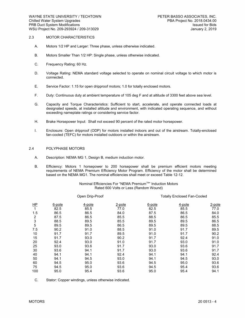
WAYNE STATE UNIVERSITY / TECHTOWN PETER BASSO ASSOCIATES, INC. Chilled Water System Upgrades PBA Project No. 2018.0434.00 PRB Duct System Modifications Issued for Bids WSU Project No. 209-293924 / 209-313029 January 2, 2019
MOTORS 20 0513 - 4
2.3 MOTOR CHARACTERISTICS
A. Motors 1/2 HP and Larger: Three phase, unless otherwise indicated.
B. Motors Smaller Than 1/2 HP: Single phase, unless otherwise indicated.
C. Frequency Rating: 60 Hz.
D. Voltage Rating: NEMA standard voltage selected to operate on nominal circuit voltage to which motor is connected.
E. Service Factor: 1.15 for open dripproof motors; 1.0 for totally enclosed motors.
F. Duty: Continuous duty at ambient temperature of 105 deg F and at altitude of 3300 feet above sea level.
G. Capacity and Torque Characteristics: Sufficient to start, accelerate, and operate connected loads at designated speeds, at installed altitude and environment, with indicated operating sequence, and without exceeding nameplate ratings or considering service factor.
H. Brake Horsepower Input: Shall not exceed 90 percent of the rated motor horsepower.
I. Enclosure: Open dripproof (ODP) for motors installed indoors and out of the airstream. Totally-enclosed fan-cooled (TEFC) for motors installed outdoors or within the airstream.
2.4 POLYPHASE MOTORS
A. Description: NEMA MG 1, Design B, medium induction motor.
B. Efficiency: Motors 1 horsepower to 200 horsepower shall be premium efficient motors meeting requirements of NEMA Premium Efficiency Motor Program. Efficiency of the motor shall be determined based on the NEMA MG1. The nominal efficiencies shall meet or exceed Table 12-12.
Nominal Efficiencies For “NEMA PremiumTM” Induction Motors Rated 600 Volts or Less (Random Wound)
Open Drip-Proof Totally Enclosed Fan-Cooled
HP 6-pole 4-pole 2-pole 6-pole 4-pole 2-pole 1 82.5 85.5 77.0 82.5 85.5 77.0
1.5 86.5 86.5 84.0 87.5 86.5 84.0 2 87.5 86.5 85.5 88.5 86.5 85.5 3 88.5 89.5 85.5 89.5 89.5 86.5 5 89.5 89.5 86.5 89.5 89.5 88.5
7.5 90.2 91.0 88.5 91.0 91.7 89.5 10 91.7 91.7 89.5 91.0 91.7 90.2 15 91.7 93.0 90.2 91.7 92.4 91.0 20 92.4 93.0 91.0 91.7 93.0 91.0 25 93.0 93.6 91.7 93.0 93.6 91.7 30 93.6 94.1 91.7 93.0 93.6 91.7 40 94.1 94.1 92.4 94.1 94.1 92.4 50 94.1 94.5 93.0 94.1 94.5 93.0 60 94.5 95.0 93.6 94.5 95.0 93.6 75 94.5 95.0 93.6 94.5 95.4 93.6
100 95.0 95.4 93.6 95.0 95.4 94.1
C. Stator: Copper windings, unless otherwise indicated.

WAYNE STATE UNIVERSITY / TECHTOWN PETER BASSO ASSOCIATES, INC. Chilled Water System Upgrades PBA Project No. 2018.0434.00 PRB Duct System Modifications Issued for Bids WSU Project No. 209-293924 / 209-313029 January 2, 2019
MOTORS 20 0513 - 5
D. Rotor: Squirrel cage, unless otherwise indicated.
E. Bearings: Grease lubricated anti-friction ball bearings with housings equipped with plugged provision for relubrication, rated for minimum ABMA 9, L-10 life of 120,000 hours. Calculate bearing load with NEMA minimum V- belt pulley with belt center line at end of NEMA standard shaft extension. Stamp bearing sizes on nameplate.
F. Temperature Rise: Match insulation rating, unless otherwise indicated.
G. Insulation: Class F, unless otherwise indicated.
H. Code Letter Designation:
1. Motors 10 HP and Larger: NEMA starting Code (KVA Code) F or G. 2. Motors Smaller Than 10 HP: Manufacturer's standard starting characteristic.
I. Enclosure: Cast iron for motors 7.5 hp and larger; rolled steel for motors smaller than 7.5 hp.
1. Finish: Gray enamel.
J. Sound Level: Not to exceed NEMA MG-1 12.54.
2.5 POLYPHASE MOTORS WITH ADDITIONAL REQUIREMENTS
A. Motors Used with Variable Frequency Controllers: Ratings, characteristics, and features coordinated with and approved by controller manufacturer.
1. Windings: Copper magnet wire with moisture-resistant insulation varnish, designed and tested to resist transient spikes, high frequencies, and short time rise pulses produced by pulse-width modulated inverters.
2. Premium-Efficient Motors: Class B temperature rise; Class F insulation.
B. Shaft Grounding: Provide a means to protect motor from common mode currents.
1. Required for:
a. Motors used with variable frequency controllers. b. Motors 100 HP and larger.
2. Manufacturers: Subject to compliance with requirements, provide products by one of the following:
a. Electro Static Technology, Inc.; Aegis SGR Conductive Microfiber.
C. Severe-Duty Motors: Totally enclosed, with 1.25 minimum service factor, greased bearings, integral condensate drains, and capped relief vents. Windings insulated with nonhygroscopic material.
1. Finish: Chemical-resistant paint over corrosion-resistant primer.
D. Source Quality Control: Perform the following tests on each motor according to NEMA MG 1:
1. Measure winding resistance. 2. Read no-load current and speed at rated voltage and frequency. 3. Measure locked rotor current at rated frequency. 4. Perform high-potential test.
WAYNE STATE UNIVERSITY / TECHTOWN PETER BASSO ASSOCIATES, INC. Chilled Water System Upgrades PBA Project No. 2018.0434.00 PRB Duct System Modifications Issued for Bids WSU Project No. 209-293924 / 209-313029 January 2, 2019
MOTORS 20 0513 - 6
2.6 SINGLE-PHASE MOTORS
A. Type: One of the following, to suit starting torque and requirements of specific motor application:
1. Permanent-split capacitor. 2. Split-phase start, capacitor run. 3. Capacitor start, capacitor run.
B. Shaded-Pole Motors: For motors 1/20 hp and smaller only.
C. Thermal Protection: Internal protection to automatically open power supply circuit to motor when winding temperature exceeds a safe value calibrated to temperature rating of motor insulation. Thermal-protection device shall automatically reset when motor temperature returns to normal range.
D. Bearings: Ball type for belt-connected motors and other motors with high radial forces on motor shaft; sealed, prelubricated-sleeve type for other single-phase motors.
2.7 ENCLOSED CONTROLLERS
A. Provide enclosed controllers in accordance with requirements specified in Division 26 Section “Enclosed Controllers”.
2.8 ENCLOSED SWITCHES AND CIRCUIT BREAKERS
A. Provide enclosed switches and circuit breakers in accordance with requirements specified in Division 26 Section “Enclosed Switches and Circuit Breakers”.
2.9 FUSES
A. Provide fuses in accordance with requirements specified in Division 26 Section “Fuses”.
PART 3 - EXECUTION
3.1 FIELD QUALITY CONTROL
A. All three phase motors 1/2 HP and above shall be tested by the Testing Agency.
B. Prepare for acceptance tests as follows:
1. Check motor nameplates for horsepower, speed, phase and voltage. 2. Check coupling alignment and shaft end play. 3. Run each motor with its controller. Demonstrate correct rotation, alignment, and speed at motor
design load. 4. Test interlocks and control features for proper operation. 5. Verify that current in each phase is within nameplate rating.
C. Testing: Owner will engage a qualified testing agency to perform the following field quality-control testing:
D. Testing: Engage a qualified testing agency to perform the following field quality-control testing:
E. Testing: Perform the following field quality-control testing:

WAYNE STATE UNIVERSITY / TECHTOWN PETER BASSO ASSOCIATES, INC. Chilled Water System Upgrades PBA Project No. 2018.0434.00 PRB Duct System Modifications Issued for Bids WSU Project No. 209-293924 / 209-313029 January 2, 2019
MOTORS 20 0513 - 7
1. Perform each electrical test and visual and mechanical inspection stated in NETA ATS, Section 7.15.1. Certify compliance with test parameters.
2. Jog motor as required to verify proper phase and shaft rotation. Immediately after start-up, check bearing temperature and smooth operation. Take current reading at full load using a clamp-on ammeter. If ammeter reading is over the rated full load current, determine reason for discrepancy and take necessary corrective actions. Record all readings, motor nameplate data and overload heater data.
3. Correct malfunctioning units on-site, where possible, and retest to demonstrate compliance; otherwise, replace with new units and retest.
3.2 ADJUSTING
A. Align motors, bases, shafts, pulleys and belts. Tension belts according to manufacturer's written instructions.
3.3 CLEANING
A. After completing equipment installation, inspect unit components. Remove paint splatters and other spots, dirt, and debris. Repair damaged finish to match original finish.
B. Clean motors, on completion of installation, according to manufacturer's written instructions.
END OF SECTION 20 0513

WAYNE STATE UNIVERSITY / TECHTOWN PETER BASSO ASSOCIATES, INC. Chilled Water System Upgrades PBA Project No. 2018.0434.00 PRB Duct System Modifications Issued for Bids WSU Project No. 209-293924 / 209-313029 January 2, 2019
PIPE FLEXIBLE CONNECTORS, EXPANSION FITTINGS AND LOOPS 20 0516 - 1
SECTION 20 0516 – PIPE FLEXIBLE CONNECTORS, EXPANSION FITTINGS AND LOOPS
PART 1 - GENERAL ...................................................................................................................................................... 1
1.1 RELATED DOCUMENTS ............................................................................................................................. 1
1.2 DEFINITIONS ............................................................................................................................................... 1
1.3 PERFORMANCE REQUIREMENTS ............................................................................................................ 1
1.4 SUBMITTALS ............................................................................................................................................... 2
1.5 QUALITY ASSURANCE ............................................................................................................................... 2
PART 2 - PRODUCTS ................................................................................................................................................... 2
2.1 MANUFACTURERS ..................................................................................................................................... 2
2.2 FLEXIBLE CONNECTORS ........................................................................................................................... 3
PART 3 - EXECUTION .................................................................................................................................................. 3
3.1 FLEXIBLE CONNECTOR APPLICATIONS .................................................................................................. 3
PART 1 - GENERAL
1.1 RELATED DOCUMENTS
A. Drawings and general provisions of the Contract, including General and Supplementary Conditions and Division 01 Specification Sections, apply to this Section.
B. Related Sections include the following:
1. Division 20 Section “Mechanical General Requirements.” 2. Division 20 Section “Basic Mechanical Materials and Methods.”
1.2 DEFINITIONS
A. BR: Butyl rubber.
B. CR: Chlorosulfonated polyethylene synthetic rubber (Neoprene).
C. CSM: Chlorosulfonyl-polyethylene rubber (Hypalon).
D. EPDM: Ethylene-propylene-diene terpolymer rubber.
E. NBR: Buna-N/Nitrile rubber.
F. NR: Natural rubber.
G. PTFE: Polytetrafluoroethylene plastic.
1.3 PERFORMANCE REQUIREMENTS
A. Compatibility: Products shall be suitable for piping system fluids, materials, working pressures, and temperatures.
B. Capability: Products shall absorb 150 percent of maximum axial movement between anchors.
WAYNE STATE UNIVERSITY / TECHTOWN PETER BASSO ASSOCIATES, INC. Chilled Water System Upgrades PBA Project No. 2018.0434.00 PRB Duct System Modifications Issued for Bids WSU Project No. 209-293924 / 209-313029 January 2, 2019
PIPE FLEXIBLE CONNECTORS, EXPANSION FITTINGS AND LOOPS 20 0516 - 2
1.4 SUBMITTALS
A. Product Data: For each type of pipe flexible connector, expansion joint and alignment guide indicated.
B. Delegated-Design Submittal:
1. Design calculations and detailed fabrication and assembly of pipe anchors and alignment guides for multiple pipes, expansion joints and loops, and attachments of the same to the building structure.
2. Locations of pipe anchors and alignment guides and expansion joints and loops.
C. Shop Drawings: Signed and sealed by a qualified professional engineer.
1. Design Calculations: Calculate requirements for thermal expansion of piping systems and for selecting and designing expansion joints, loops, and bends.
2. Anchor Details: Detail fabrication of each anchor indicated. Show dimensions and methods of assembly and attachment to building structure.
3. Alignment Guide Details: Detail field assembly and attachment to building structure. 4. Schedule: Indicate type, manufacturer's number, size, material, pressure rating, end connections,
and location for each expansion joint.
D. Product Certificates: For each type of pipe expansion joint, signed by product manufacturer.
E. Welding certificates.
F. Operation and Maintenance Data: For pipe expansion joints to include in operation and maintenance manuals.
1.5 QUALITY ASSURANCE
A. Welding: Qualify procedures and personnel according to the following:
1. Steel Shapes and Plates: AWS D1.1, "Structural Welding Code - Steel." 2. Welding to Piping: ASME Boiler and Pressure Vessel Code: Section IX.
B. Regulatory Requirements: Comply with requirements in Public Law 111-380, "Reduction of Lead in Drinking Water Act," about lead content in materials that will be in contact with potable water for human consumption.
C. Comply with NSF 61, "Drinking Water System Components - Health Effects; Sections 1 through 9," and NSF 372 Drinking Water System Components – Lead Content for potable domestic water piping and components.
PART 2 - PRODUCTS
2.1 MANUFACTURERS
A. In other Part 2 articles where titles below introduce lists, the following requirements apply to product selection:
1. Manufacturers: Subject to compliance with requirements, provide products by one of the manufacturers specified.

WAYNE STATE UNIVERSITY / TECHTOWN PETER BASSO ASSOCIATES, INC. Chilled Water System Upgrades PBA Project No. 2018.0434.00 PRB Duct System Modifications Issued for Bids WSU Project No. 209-293924 / 209-313029 January 2, 2019
PIPE FLEXIBLE CONNECTORS, EXPANSION FITTINGS AND LOOPS 20 0516 - 3
2.2 FLEXIBLE CONNECTORS
A. Rubber Flexible Connectors/Expansion Joints: ASTM F 1123, fabric-reinforced rubber with external control rods or cables, and complying with FSA's "Technical Handbook: Non-Metallic Expansion Joints and Flexible Pipe Connectors."
1. Manufacturers:
a. Flex-Weld, Inc./Keflex. b. Mason Industries, Inc.; Mercer Rubber Co. c. Metraflex, Inc. d. Senior Flexonics, Inc.; Pathway Division. e. Twin City Hose, Inc. f. Vibration Mountings & Controls, Inc.
2. Arch Type: Single or multiple arches. 3. Spherical Type: Single or multiple spheres.
a. Working Pressure Ratings for NPS 1-1/2 to NPS 4: 225 psig at 170 deg F. b. Working Pressure Ratings for NPS 5 and NPS 6: 225 psig at 170 deg F. c. Working Pressure Ratings for NPS 8 to NPS 12: 225 psig at 170 deg F. d. Working Pressure Ratings for NPS 14: 150 psig at 170 deg F. e. Working Pressure Ratings for NPS 16 to NPS 20: 125 psig at 170 deg F. f. Working Pressure Ratings for NPS 24: 110 psig at 170 deg F.
4. Material: EPDM, and suitable for ethylene glycol solution. 5. End Connections: Full-faced, integral, steel flanges with steel retaining rings.
PART 3 - EXECUTION
3.1 FLEXIBLE CONNECTOR APPLICATIONS
A. Use rubber flexible pipe connectors at the inlet and outlet water connections of base mounted pumps, chillers, and cooling towers, unless otherwise indicated.
1. Rubber Flexible Connectors for Pipe Sized NPS 2 and Smaller: Twin-sphere with females union end connections.
2. Rubber Flexible Connectors for Pipe Sized NPS 2-1/2 and Larger: Twin-sphere with floating flange end connections.
END OF SECTION 20 0516

WAYNE STATE UNIVERSITY / TECHTOWN PETER BASSO ASSOCIATES, INC. Chilled Water System Upgrades PBA Project No. 2018.0434.00 PRB Duct System Modifications Issued for Bids WSU Project No. 209-293924 / 209-313029 January 2, 2019
METERS AND GAGES 20 0519 - 1
SECTION 20 0519 - METERS AND GAGES
PART 1 - GENERAL ...................................................................................................................................................... 1
1.1 RELATED DOCUMENTS ............................................................................................................................. 1
1.2 DEFINITIONS ............................................................................................................................................... 1
1.3 SUBMITTALS ............................................................................................................................................... 1
1.4 QUALITY ASSURANCE ............................................................................................................................... 2
PART 2 - PRODUCTS ................................................................................................................................................... 2
2.1 MANUFACTURERS ..................................................................................................................................... 2
2.2 PLASTIC-CASE, LIQUID-IN-GLASS THERMOMETERS ............................................................................. 2
2.3 THERMOWELLS .......................................................................................................................................... 3
2.4 PRESSURE GAGES .................................................................................................................................... 3
2.5 FLOW MEASURING DEVICES .................................................................................................................... 3
2.6 MAGNETIC INDUCTIVE FLOWMETER (INSERTION TYPE) ...................................................................... 4
PART 3 - EXECUTION .................................................................................................................................................. 5
3.1 THERMOMETER APPLICATIONS ............................................................................................................... 5
3.2 GAGE APPLICATIONS ................................................................................................................................ 5
3.3 INSTALLATIONS .......................................................................................................................................... 5
3.4 CONNECTIONS ........................................................................................................................................... 5
3.5 ADJUSTING .................................................................................................................................................. 6
PART 1 - GENERAL
1.1 RELATED DOCUMENTS
A. Drawings and general provisions of the Contract, including General and Supplementary Conditions and Division 01 Specification Sections, apply to this Section.
B. Related Sections include the following:
1. Division 20 Section “Mechanical General Requirements.” 2. Division 20 Section “Basic Mechanical Materials and Methods.”
1.2 DEFINITIONS
A. CR: Chlorosulfonated polyethylene synthetic rubber.
B. EPDM: Ethylene-propylene-diene terpolymer rubber.
C. FPR: Fiberglass reinforced plastic.
1.3 SUBMITTALS
A. Product Data: For each type of product indicated; include performance curves.
B. Shop Drawings: Schedule for the following indicating manufacturer's number, scale range, and location for each:
1. Thermometers. 2. Gages. 3. Flowmeters.
WAYNE STATE UNIVERSITY / TECHTOWN PETER BASSO ASSOCIATES, INC. Chilled Water System Upgrades PBA Project No. 2018.0434.00 PRB Duct System Modifications Issued for Bids WSU Project No. 209-293924 / 209-313029 January 2, 2019
METERS AND GAGES 20 0519 - 2
C. Product Certificates: For the following signed by product manufacturer:
1. Thermometers. 2. Gages. 3. Flowmeters.
D. Operation and Maintenance Data: For the following to include in operation and maintenance manuals:
1. Flowmeters.
1.4 QUALITY ASSURANCE
A. Regulatory Requirements: Comply with requirements in Public Law 111-380, "Reduction of Lead in Drinking Water Act," about lead content in materials that will be in contact with potable water for human consumption.
PART 2 - PRODUCTS
2.1 MANUFACTURERS
A. In other Part 2 articles where titles below introduce lists, the following requirements apply to product selection:
1. Manufacturers: Subject to compliance with requirements, provide products by one of the manufacturers specified.
2.2 PLASTIC-CASE, LIQUID-IN-GLASS THERMOMETERS
A. Manufacturers:
1. AMETEK, Inc.; U.S. Gauge Div. 2. Marsh Bellofram. 3. Miljoco Corp. 4. REOTEMP Instrument Corporation. 5. Trerice, H. O. Co. 6. Weksler Instruments Operating Unit; Dresser Industries; Instrument Div.
B. Case: Plastic, 9 inches long.
C. Tube: Red, blue, or green reading, organic-liquid filled, with magnifying lens.
D. Tube Background: Satin-faced, nonreflective aluminum with permanently etched scale markings.
E. Window: Glass or plastic.
F. Connector: Adjustable type, 180 degrees in vertical plane, 360 degrees in horizontal plane, with locking device.
G. Stem: Metal, for thermowell installation and of length to suit installation.
H. Accuracy: Plus or minus 1 percent of range or plus or minus 1 scale division to maximum of 1.5 percent of range.

WAYNE STATE UNIVERSITY / TECHTOWN PETER BASSO ASSOCIATES, INC. Chilled Water System Upgrades PBA Project No. 2018.0434.00 PRB Duct System Modifications Issued for Bids WSU Project No. 209-293924 / 209-313029 January 2, 2019
METERS AND GAGES 20 0519 - 3
2.3 THERMOWELLS
A. Manufacturers: Same as manufacturer of thermometer being used.
B. Description: Pressure-tight, socket-type metal fitting made for insertion into piping and of type, diameter, and length required to hold thermometer. Brass for compatible services less than 353 degrees F (178 degrees C); ANSI 18-8 stainless steel for all others to suit service. Furnish extension neck to accommodate insulation where applicable.
2.4 PRESSURE GAGES
A. Manufacturers:
1. AMETEK, Inc.; U.S. Gauge Div. 2. Cambridge. 3. Dwyer Instruments, Inc. 4. Marsh Bellofram. 5. Miljoco Corporation. 6. Trerice, H. O. Co. 7. Weiss Instruments, Inc. 8. Weksler Instruments Operating Unit; Dresser Industries; Instrument Div.
B. Direct-Mounting, Dial-Type Pressure Gages: Indicating-dial type complying with ASME B40.100.
1. Case: Stainless steel, aluminum, or FRP, 4-1/2-inchdiameter.
2. Pressure-Element Assembly: Bourdon tube, unless otherwise indicated. 3. Pressure Connection: Brass, NPS 1/4, bottom-outlet type unless back-outlet type is indicated. 4. Movement: Mechanical, with link to pressure element and connection to pointer. 5. Dial: Satin-faced, nonreflective aluminum with permanently etched scale markings. 6. Pointer: Red or other dark-color metal. 7. Window: Glass or plastic. 8. Ring: Stainless steel or chrome plated metal. 9. Accuracy: Grade A, plus or minus 1 percent of middle half scale. 10. Water: 0-100 PSIG (1 psi divisions to 50 psi; 5 psi divisions above 50 psi), liquid filled. 11. Range for Fluids under Pressure: 1-1/2 times expected working pressure. If not a standard scale,
select next largest scale.
C. Pressure-Gage Fittings:
1. Valves: NPS 1/4 brass ball type. 2. Syphons: NPS 1/4 coil of brass tubing with threaded ends. 3. Snubbers: ASME B40.5, NPS 1/4 brass bushing with corrosion-resistant, porous-metal disc of
material suitable for system fluid and working pressure.
2.5 FLOW MEASURING DEVICES
A. Manufacturers:
1. Dietrich Standard Subsidiary of Rosemount Division of Emerson Process Management; Diamond II - Flo-Tap Model.
2. Preso Meters Corporation. 3. Taco, Inc.
B. Flow measuring device shall be used where indicated on the drawings and in sizes NPS 6 and larger and shall be annular primary flow elements. The annular primary flow elements shall be type 316, stainless steel, diamond shape or elliptical shape in cross-section. Pressure rating shall meet or exceed system

WAYNE STATE UNIVERSITY / TECHTOWN PETER BASSO ASSOCIATES, INC. Chilled Water System Upgrades PBA Project No. 2018.0434.00 PRB Duct System Modifications Issued for Bids WSU Project No. 209-293924 / 209-313029 January 2, 2019
METERS AND GAGES 20 0519 - 4
minimum pressure rating as indicated for each system. Provide permanent, rust-proof metal identification tag on a chain indicating design flow rates, metered fluid and line size. Flow measuring devices shall be weld insert type. Units shall be capable of being inserted without system shut-down.
C. Accuracy shall be plus or minus 1 percent over a flow turndown at least 10 to 1, independent of Reynold's number. Repeatability shall be plus or minus 0.1 percent.
D. Sensors shall be installed in strict accordance with the manufacturer's recommendations with special attention given to alignment and straight run requirements.
2.6 MAGNETIC INDUCTIVE FLOWMETER (INSERTION TYPE)
A. Manufacturers:
1. KOBOLD Instruments Inc.; Model PME-12R40. 2. KROHNE Inc.
B. Description: Magnetic inductive flowmeter for measuring the flow of conductive liquids in pipes and suitable for installation in pipes size NPS 1-1/2 to NPS 12.
C. Input Power: 24 VDC, 2.5 watts.
D. Current Output: 4-20mA, active bi-directional measurement, output always positive.
E. Temperature Ratings:
1. Ambient Temperature: 140 deg F maximum. 2. Measured Fluid Temperature: 0 to 212 deg F.
F. Pressure Rating: 230 psig at 75 deg F.
G. Transmitter Span: 1-5 meters/second (adjustable).
H. Accuracy: Plus or minus 2 percent of velocity at the measuring electrode.
I. Repeatability: Plus or minus 2 percent of measured value.
J. Noise Immunity: CE per EN 50081-1-2 and EN 50082-1-2.
K. Electrical Protection (Enclosure) Type: NEMA 4X/IP 65.
L. Wetted Parts:
1. Sensor Tip: PVDF with Viton O-ring. 2. Electrodes: Type 316 L stainless steel. 3. Flow Transmitter: Provided with Type 316L stainless steel weld sleeve. 4. Sealing Ring: Buna-N.
M. Case: Aluminum, epoxy powder coated.

WAYNE STATE UNIVERSITY / TECHTOWN PETER BASSO ASSOCIATES, INC. Chilled Water System Upgrades PBA Project No. 2018.0434.00 PRB Duct System Modifications Issued for Bids WSU Project No. 209-293924 / 209-313029 January 2, 2019
METERS AND GAGES 20 0519 - 5
PART 3 - EXECUTION
3.1 THERMOMETER APPLICATIONS
A. Install liquid-in-glass thermometers where indicated.
B. Provide the following temperature ranges for thermometers: 1. Air Ducts: 0 to 120 Deg F. 2. Chilled Water/Condenser Water: 30 to 130 deg F or 0 to 120 Deg F.
3.2 GAGE APPLICATIONS
A. Install liquid-filled-case-type pressure gages where indicated.
B. Except where noted otherwise, select range for twice normal operating pressure.
1. Chilled Water: 0 to 100 psig.
3.3 INSTALLATIONS
A. Install direct-mounting thermometers and adjust vertical and tilted positions.
B. Install thermowells with socket extending to center of pipe a minimum of 2 inches into fluid and in vertical position in piping tees where thermometers are indicated.
C. Duct Thermometer Support Flanges: Install in wall of duct where duct thermometers are indicated. Attach to duct with screws.
D. Install direct-mounting pressure gages in piping tees with pressure gage located on pipe at most readable position.
E. Install ball valve and snubber fitting in piping for each pressure gage for fluids.
F. Assemble and install connections, tubing, and accessories between flow-measuring elements and flowmeters as prescribed by manufacturer's written instructions.
G. Install flowmeter elements in accessible positions in piping systems.
3.4 CONNECTIONS
A. Install meters and gages adjacent to machines and equipment to allow service and maintenance for meters, gages, machines, and equipment.
B. Connect flowmeter-system elements to meters.
C. Connect flowmeter transmitters to meters.
D. Ground equipment according to Division 26 Section "Grounding and Bonding."
E. Connect wiring according to Division 26 Section "Conductors and Cables."

WAYNE STATE UNIVERSITY / TECHTOWN PETER BASSO ASSOCIATES, INC. Chilled Water System Upgrades PBA Project No. 2018.0434.00 PRB Duct System Modifications Issued for Bids WSU Project No. 209-293924 / 209-313029 January 2, 2019
METERS AND GAGES 20 0519 - 6
3.5 ADJUSTING
A. Calibrate meters according to manufacturer's written instructions, after installation.
B. Adjust faces of meters and gages to proper angle for best visibility.
END OF SECTION 20 0519
WAYNE STATE UNIVERSITY / TECHTOWN PETER BASSO ASSOCIATES, INC. Chilled Water System Upgrades PBA Project No. 2018.0434.00 PRB Duct System Modifications Issued for Bids WSU Project No. 209-293924 / 209-313029 January 2, 2019
HANGERS AND SUPPORTS 20 0529 - 1
SECTION 20 0529 - HANGERS AND SUPPORTS
PART 1 - GENERAL ...................................................................................................................................................... 1
1.1 RELATED DOCUMENTS ............................................................................................................................. 1
1.2 DEFINITIONS ............................................................................................................................................... 1
1.3 PERFORMANCE REQUIREMENTS ............................................................................................................ 1
1.4 SUBMITTALS ............................................................................................................................................... 2
1.5 QUALITY ASSURANCE ............................................................................................................................... 2
PART 2 - PRODUCTS ................................................................................................................................................... 2
2.1 MANUFACTURERS ..................................................................................................................................... 2
2.2 HANGER ROD MATERIAL ........................................................................................................................... 2
2.3 STEEL PIPE HANGERS AND SUPPORTS.................................................................................................. 2
2.4 TRAPEZE PIPE HANGERS .......................................................................................................................... 3
2.5 METAL FRAMING SYSTEMS ...................................................................................................................... 3
2.6 METAL INSULATION SHIELDS ................................................................................................................... 3
2.7 PIPE COVERING PROTECTION SADDLES................................................................................................ 3
2.8 THERMAL-HANGER SHIELDS .................................................................................................................... 4
2.9 FASTENER SYSTEMS ................................................................................................................................. 5
2.10 ROOF MOUNTED PIPING SUPPORTS ....................................................................................................... 5
2.11 MISCELLANEOUS MATERIALS .................................................................................................................. 5
PART 3 - EXECUTION .................................................................................................................................................. 5
3.1 HANGER AND SUPPORT APPLICATIONS ................................................................................................. 5
3.2 HANGER AND SUPPORT INSTALLATION ................................................................................................. 6
3.3 EQUIPMENT SUPPORTS ............................................................................................................................ 9
3.4 METAL FABRICATIONS............................................................................................................................... 9
3.5 ADJUSTING .................................................................................................................................................. 9
3.6 PAINTING ..................................................................................................................................................... 9
PART 1 - GENERAL
1.1 RELATED DOCUMENTS
A. Drawings and general provisions of the Contract, including General and Supplementary Conditions and Division 01 Specification Sections, apply to this Section.
B. Related Sections include the following:
1. Division 20 Section “Mechanical General Requirements.” 2. Division 20 Section “Basic Mechanical Materials and Methods.” 3. Division 20 Section "Mechanical Vibration Controls" for vibration isolation devices. 4. Division 23 Section(s) "Metal Ducts" for duct hangers and support.
1.2 DEFINITIONS
A. MSS: Manufacturers Standardization Society for the Valve and Fittings Industry Inc.
B. MFMA: Metal Framing Manufacturers Association.
1.3 PERFORMANCE REQUIREMENTS
A. Design supports for multiple pipes, including pipe stands, capable of supporting combined weight of supported systems, system contents, and test water.
WAYNE STATE UNIVERSITY / TECHTOWN PETER BASSO ASSOCIATES, INC. Chilled Water System Upgrades PBA Project No. 2018.0434.00 PRB Duct System Modifications Issued for Bids WSU Project No. 209-293924 / 209-313029 January 2, 2019
HANGERS AND SUPPORTS 20 0529 - 2
B. Design equipment supports capable of supporting combined operating weight of supported equipment and connected systems and components.
1.4 SUBMITTALS
A. Product Data: For the following:
1. Steel pipe hangers and supports. 2. Thermal-hanger shield inserts.
B. Welding certificates.
1.5 QUALITY ASSURANCE
A. MSS Standards: Pipe hangers, supports, and accessories shall comply with the following:
1. MSS SP-58, Pipe Hangers and Supports – Materials, Design and Manufacture, Selection, Application, and Installation.
B. Welding: Qualify procedures and personnel according to the following:
1. AWS D1.1, "Structural Welding Code--Steel." 2. AWS D1.2, "Structural Welding Code--Aluminum." 3. AWS D1.3, "Structural Welding Code--Sheet Steel." 4. AWS D1.4, "Structural Welding Code--Reinforcing Steel." 5. ASME Boiler and Pressure Vessel Code: Section IX.
PART 2 - PRODUCTS
2.1 MANUFACTURERS
A. In other Part 2 articles where titles below introduce lists, the following requirements apply to product selection:
1. Manufacturers: Subject to compliance with requirements, provide products by one of the manufacturers specified.
2.2 HANGER ROD MATERIAL
A. Threaded, hot rolled, steel rod conforming to ASTM A 36 or A575.
1. Rod continuously threaded. 2. Use of rod couplings is prohibited.
2.3 STEEL PIPE HANGERS AND SUPPORTS
A. Description: MSS SP-58, Types 1 through 58, factory-fabricated components. Refer to Part 3 "Hanger and Support Applications" Article, and schedules and details on the Drawings for where to use specific hanger and support types.
B. Manufacturers:

WAYNE STATE UNIVERSITY / TECHTOWN PETER BASSO ASSOCIATES, INC. Chilled Water System Upgrades PBA Project No. 2018.0434.00 PRB Duct System Modifications Issued for Bids WSU Project No. 209-293924 / 209-313029 January 2, 2019
HANGERS AND SUPPORTS 20 0529 - 3
1. Anvil International, Inc. 2. B-Line by Eaton. 3. Carpenter & Paterson, Inc. 4. Hilti USA. 5. nVent Electric plc; CADDY. 6. PHD Manufacturing, Inc.
C. Galvanized, Metallic Coatings: Pregalvanized or hot dipped.
2.4 TRAPEZE PIPE HANGERS
A. Description: MSS SP-58, Type 59, shop- or field-fabricated pipe-support assembly made from structural-steel shapes with MSS SP-58 hanger rods, nuts, saddles, and U-bolts.
2.5 METAL FRAMING SYSTEMS
A. Description: MFMA-3, shop- or field-fabricated pipe-support assembly made of steel channels and other components.
B. Manufacturers:
1. Anvil International, Inc.; Anvil-Strut. 2. B-Line by Eaton. 3. Power-Strut; a part of Atkore International. 4. Unistrut; a part of Atkore International. 5. Hilti USA.
C. Coatings: Manufacturer's standard finish, unless bare metal surfaces are indicated.
D. Galvanized, Metallic Coatings: Pregalvanized or hot dipped.
E. Nonmetallic Coatings: Plastic coating, jacket, or liner.
2.6 METAL INSULATION SHIELDS
A. Manufacturers:
1. Anvil International, Inc. 2. B-Line by Eaton. 3. Carpenter & Paterson, Inc. 4. nVent Electric plc; CADDY. 5. PHD Manufacturing, Inc.
B. Description: MSS SP-58, Type 40, protective shields. Shields shall span an arc of 180 degrees.
C. Shield Dimensions for Pipe: Not less than the following:
1. NPS 1/4 to NPS 2: 12 inches long and 0.048 inch thick.
2.7 PIPE COVERING PROTECTION SADDLES
A. Manufacturers:

WAYNE STATE UNIVERSITY / TECHTOWN PETER BASSO ASSOCIATES, INC. Chilled Water System Upgrades PBA Project No. 2018.0434.00 PRB Duct System Modifications Issued for Bids WSU Project No. 209-293924 / 209-313029 January 2, 2019
HANGERS AND SUPPORTS 20 0529 - 4
1. Anvil International, Inc. 2. B-Line by Eaton. 3. Carpenter & Paterson, Inc. 4. nVent Electric plc; CADDY. 5. PHD Manufacturing, Inc.
B. Description: MSS SP-58, Type 39A and Type 39B, for suspension of insulated hot pipe where heat losses are to be kept to a minimum.
1. Saddles shall match insulation thickness. 2. Saddle length: 12 inches. 3. Furnish with center rib for pipe sized NPS 12 and larger.
2.8 THERMAL-HANGER SHIELDS
A. Manufacturers:
1. American Mechanical Insulation Sales Inc. (AMIS). 2. B-Line by Eaton. 3. nVent Electric plc; CADDY. 4. Pipe Shields, Inc.; a subsidiary of Piping Technology & Products, Inc. 5. Rilco Manufacturing Company, Inc. 6. Value Engineered Products, Inc.
B. Description: Manufactured assembly consisting of insulation insert encased in 360 degree sheet metal shield.
1. Minimum Compressive Strength of Insert Material:
a. 100-psig- for sizes smaller than NPS 6. b. 600-psig- for sizes NPS 6 and larger.
C. Insulation-Insert Material for Cold Piping: Full 360 degree, water-repellent treated, ASTM C 533, Type I calcium silicate with vapor barrier.
D. Insulation-Insert Material for Roof Mounted Piping: Full 360 degree, high density, polyisocyanurate with 360 degree galvanized steel saddle.
E. Insulation-Insert Material for Hot Piping: Full 360 degree, water-repellent treated, ASTM C 533, Type I calcium silicate.
F. Insert Length: Extend 2 inches beyond sheet metal shield for piping operating below ambient air temperature.
G. Include carbon steel ASTM A36 load distribution plates as required by load, pipe movement, hanger style, and hanger spacing.
H. Thermal-Hanger Shields for Small Diameter Piping:
1. Manufacturer:
a. Hydra-Zorb Company; Klo-Shure Insulation Couplings.
2. Insulation-Insert Material for Small Diameter Piping with Flexible Foamed Elastomeric or Glass Fiber Insulation: Use the following:

WAYNE STATE UNIVERSITY / TECHTOWN PETER BASSO ASSOCIATES, INC. Chilled Water System Upgrades PBA Project No. 2018.0434.00 PRB Duct System Modifications Issued for Bids WSU Project No. 209-293924 / 209-313029 January 2, 2019
HANGERS AND SUPPORTS 20 0529 - 5
a. Rigid Hytrel thermoplastic insulation coupling designed for use with pipe or tube NPS 4 and smaller, and insulation from 3/8 inch to 1-1/2 inch thick.
2.9 FASTENER SYSTEMS
A. Mechanical-Expansion Anchors: Insert-wedge-type zinc-coated steel, for use in hardened portland cement concrete with pull-out, tension, and shear capacities appropriate for supported loads and building materials where used.
1. Manufacturers:
a. B-Line by Eaton. b. Empire Industries, Inc. c. Hilti, Inc. d. ITW Ramset/Red Head. e. MKT Fastening, LLC. f. Powers Fasteners.
2.10 ROOF MOUNTED PIPING SUPPORTS
A. Pipe Stands, General: Shop or field-fabricated assemblies made of manufactured corrosion-resistant components to support roof-mounted piping.
B. Refer to drawing details.
2.11 MISCELLANEOUS MATERIALS
A. Structural Steel: ASTM A 36/A 36M, steel plates, shapes, and bars; black and galvanized.
B. Grout: ASTM C 1107, factory-mixed and -packaged, dry, hydraulic-cement, nonshrink and nonmetallic grout; suitable for interior and exterior applications.
1. Properties: Nonstaining, noncorrosive, and nongaseous. 2. Design Mix: 5000-psi, 28-day compressive strength.
PART 3 - EXECUTION
3.1 HANGER AND SUPPORT APPLICATIONS
A. Refer to application schedules on the Drawings.
B. For insulated pipe, oversize hanger elements to accommodate insulation thickness.
C. Specific hanger and support requirements are specified in Sections specifying piping systems and equipment.
D. Comply with MSS SP-58 for pipe hanger selections and applications that are not specified in piping system Sections.
E. Use hangers and supports with galvanized, metallic coatings for outdoor applications or where exposed to outdoor conditions.

WAYNE STATE UNIVERSITY / TECHTOWN PETER BASSO ASSOCIATES, INC. Chilled Water System Upgrades PBA Project No. 2018.0434.00 PRB Duct System Modifications Issued for Bids WSU Project No. 209-293924 / 209-313029 January 2, 2019
HANGERS AND SUPPORTS 20 0529 - 6
F. Vertical-Piping Clamps: Unless otherwise indicated and except as specified in piping system Sections, install the following types:
1. MSS Type 8 or spring type to meet system requirements.
G. Hanger-Rod Attachments: Unless otherwise indicated and except as specified in piping system Sections, install the following types:
1. Steel Turnbuckles (MSS Type 13): For adjustment up to 6 inches for heavy loads. 2. Steel Clevises (MSS Type 14): For 120 to 450 deg F piping installations. 3. Swivel Turnbuckles (MSS Type 15): For use with MSS Type 11, split pipe rings. 4. Malleable-Iron Sockets (MSS Type 16): For attaching hanger rods to various types of building
attachments. 5. Steel Weldless Eye Nuts (MSS Type 17): For 120 to 450 deg F piping installations.
H. Concrete Structure Building Attachments: Unless otherwise indicated and except as specified in piping system Sections, install the following types:
1. Anchor Devices, Concrete and Masonry: in accordance with Group I, Group II, Type 2, Class 2, Style 1 and Style 2, Group III and Group VIII or FS FF-S-325A. Furnish cast-in floor type equipment anchor devices with adjustable positions. Furnish built in anchor devices for masonry, unless otherwise approved by the Architect. Powder actuated anchoring devices shall not be used to support any mechanical systems components.
2. Use mechanical-expansion anchors where required in concrete construction.
I. Steel Frame Structure Building Attachments: Unless otherwise indicated and except as specified in piping system Sections, install the following types:
1. Beam Clamps:
a. Center Loading: TYPE 21, 28, 29 and 30, unless otherwise indicated. Type 27 shall be allowed to support single pipes NPS 6 size or smaller only.
b. "C" Clamps: Type 19, 20 or 23, for supporting single pipes NPS 2-1/2 size or smaller only. Use of "C" clamps, or beam clamps of "C" pattern, or any modification thereof, is prohibited for supporting multiple pipes or pipes larger than NPS 2-1/2.
J. Hanger-Rod Attachments for Wood Construction: Unless otherwise indicated and except as specified in piping system Sections, install the following types:
1. All Steel Ceiling Plates: UL listed and suitable for attachment to wood beams. For pipe sizes NPS 1/2 to NPS 2. Install in accordance with manufacturer’s instructions to maintain listing.
2. Threaded Side Beam Brackets: UL listed and FMG approved, suitable for attachment to wood beams. For pipe sizes NPS 2 to NPS 4. Install in accordance with manufacturer’s instructions to maintain listing.
K. Comply with MSS SP-58 for trapeze pipe hanger selections and applications that are not specified in piping system Sections.
L. Comply with MFMA-102 for metal framing system selections and applications that are not specified in piping system Sections.
3.2 HANGER AND SUPPORT INSTALLATION
A. Steel Pipe Hanger Installation: Comply with MSS SP-58. Install hangers, supports, clamps, and attachments as required to properly support piping from building structural frame.

WAYNE STATE UNIVERSITY / TECHTOWN PETER BASSO ASSOCIATES, INC. Chilled Water System Upgrades PBA Project No. 2018.0434.00 PRB Duct System Modifications Issued for Bids WSU Project No. 209-293924 / 209-313029 January 2, 2019
HANGERS AND SUPPORTS 20 0529 - 7
B. Provide necessary piping and equipment supporting elements including: building structure attachments, supplementary steel, hanger rods, stanchions and fixtures, vertical pipe attachments, horizontal pipe attachments, anchors, guides, spring supports in accordance with the referenced codes, standards, and requirements specified. Support piping and equipment from building structure, not from roof deck, floor slab, other pipe, duct or equipment.
C. At connections between piping systems, hangers and equipment of dissimilar metals, insulate, using dielectric insulating material, nonferrous piping against direct contact with the building steel by insulating the contact point of the hanger and pipe or the hanger and building steel. Test each point of dielectric insulation with an ohm meter to ensure proper isolation of dissimilar materials. Test shall be observed by the Owner's Representative and/or Architect.
D. File and paint cut ends and shop or field prime paint supporting element components.
E. Hang piping parallel with the lines of the building, unless otherwise indicated. Route piping in an orderly manner and maintain gradient. Space piping and components so a threaded pipe fitting may be removed between adjacent pipes and so there will be not less than 1/2 inch of clear space between finished surfaces and piping. Arrange hangers on adjacent parallel service lines in line with each other.
F. Flange loads on connected equipment shall not exceed 75 percent of maximum allowed by equipment manufacturer. Flange loads in liquid containing systems shall be checked in the presence of the Architect when piping is full of liquid. No flange load is allowed on pumps, vibration isolated equipment or flexible connectors.
G. Where necessary, brace piping and supports against reaction, sway and vibration.
H. Do not hang piping from joist pans, floor decks, roof decks, equipment, ductwork, or other piping.
I. Install turnbuckles, swing eyes and clevises to accommodate temperature changes, pipe accessibility, and adjustment for load pitch. Rod couplings are not acceptable.
J. Install hangers and supports for piping at intervals specified, at locations not more than 3 feet from the ends of each runout, not more than 3 feet from connections to equipment, and not over 25 percent of specified interval from each change in direction of piping and for concentrated loads such as valves, etc.
K. Base the load rating for pipe support elements on loads imposed by insulated weight of pipe filled with water. The span deflection shall not exceed slope gradient of pipe.
L. If structural steel, roofs, or tunnels will allow support spacing greater than that shown above, Contractor shall submit proposed support system along with structural calculations documenting the allowance of such spacing, in accordance with ANSI, B31.1, and MSS Guidelines.
M. Support vertical risers independently of connected horizontal piping whenever practical, with supports at the base and at intervals to accommodate system range of load with thermal conditions. Support vertical risers at each floor penetration for piping in shafts or chases. Guide for lateral stability. Fit horizontal piping connected to moving risers with two spring supports connected adjacent to riser, spaced according to required hanger spacing.
N. For risers at temperatures of 100 deg F or less place riser clamps under fittings. Support carbon steel pipe at each operating level or floor and at not more than 15-foot intervals for pipe 2 inches and smaller, and at not more than 20 foot intervals for pipe 2-1/2 inches and larger.
O. After the piping systems have been installed, tested and placed in satisfactory operation, firmly tighten hanger rod nut and jam nut and upset threads to prevent movement of fasteners.
P. Attach supporting elements connected to structural steel columns to preclude vertical slippage and cascading failure.

WAYNE STATE UNIVERSITY / TECHTOWN PETER BASSO ASSOCIATES, INC. Chilled Water System Upgrades PBA Project No. 2018.0434.00 PRB Duct System Modifications Issued for Bids WSU Project No. 209-293924 / 209-313029 January 2, 2019
HANGERS AND SUPPORTS 20 0529 - 8
Q. Attach pipe hangers and other supporting elements to roof purlins and trusses at panel points.
R. Where eccentric loading beam clamps are approved and where other work is supported by similar eccentric loading support element from the same structural member, locate eccentric loading support elements to minimize structural member torsion load.
S. Limit the location of supporting elements for piping and equipment, when supported from roof, to panel points of the bar joists.
T. Building structure shall not be reinforced except as approved by the Architect in writing.
U. Support piping and equipment from concrete building frame, not from roof or floor slabs unless otherwise indicated.
V. Attach piping supports to the side of concrete beams and concrete joist. Provide supplementary support steel as required. Cast-in-place or drilled anchors will not be permitted in the bottom of concrete beams and concrete joist.
W. Attach piping supports to the side of concrete beams or concrete joist. Where intermediate hangers are required to meet the hanger spacing schedule, the Contractor may propose attachment of intermediate pipe supports to the bottom of the concrete slab pending submittal of a satisfactory pull out test. The Contractor shall submit pull out test criteria, pull out test results, proposed hanger detail and hanger point loads to the Architect for written approval.
X. Trapeze Pipe Hanger Installation: Comply with MSS SP-58. Arrange for grouping of parallel runs of horizontal piping and support together on field-fabricated trapeze pipe hangers.
1. Pipes of Various Sizes: Support together and space trapezes for smallest pipe size or install intermediate supports for smaller diameter pipes as specified above for individual pipe hangers.
2. Field fabricate from ASTM A 36/A 36M, steel shapes selected for loads being supported. Weld steel according to AWS D1.1.
Y. Metal Framing System Installation: Arrange for grouping of parallel runs of piping and support together on field-assembled metal framing systems.
Z. Fastener System Installation:
1. Install mechanical-expansion anchors in concrete after concrete is placed and completely cured. Install fasteners according to manufacturer's written instructions.
AA. Roof-Mounting Pipe Stand Installation: 1. Curb or Rail Mounting Type Stands: Assemble components or fabricate stand and mount on
permanent, stationary roof curb or rail. 2. Maintain support manufacturer’s recommended spacing.
BB. Install hangers and supports complete with necessary inserts, bolts, rods, nuts, washers, and other accessories.
CC. Equipment Support Installation: Fabricate from welded-structural-steel shapes.
DD. Install hangers and supports to allow controlled thermal movement of piping systems, to permit freedom of movement between pipe anchors, and to facilitate action of expansion joints, expansion loops, expansion bends, and similar units.
EE. Install lateral bracing with pipe hangers and supports to prevent swaying.
FF. Install building attachments within concrete slabs or attach to structural steel. Install additional attachments at concentrated loads, including valves, flanges, and strainers, NPS 2-1/2 and larger and at changes in
WAYNE STATE UNIVERSITY / TECHTOWN PETER BASSO ASSOCIATES, INC. Chilled Water System Upgrades PBA Project No. 2018.0434.00 PRB Duct System Modifications Issued for Bids WSU Project No. 209-293924 / 209-313029 January 2, 2019
HANGERS AND SUPPORTS 20 0529 - 9
direction of piping. Install concrete inserts before concrete is placed; fasten inserts to forms and install reinforcing bars through openings at top of inserts.
GG. Load Distribution: Install hangers and supports so piping live and dead loads and stresses from movement will not be transmitted to connected equipment.
HH. Pipe Slopes: Install hangers and supports to provide indicated pipe slopes and so maximum pipe deflections allowed by ASME B31.1 (for power piping) and ASME B31.9 (for building services piping) are not exceeded.
II. Refer to individual piping sections for hanger spacing and hanger rod sizes.
3.3 EQUIPMENT SUPPORTS
A. Fabricate structural-steel stands to suspend equipment from structure overhead or to support equipment above floor.
B. Grouting: Place grout under supports for equipment and make smooth bearing surface.
C. Provide lateral bracing, to prevent swaying, for equipment supports.
3.4 METAL FABRICATIONS
A. Cut, drill, and fit miscellaneous metal fabrications for trapeze pipe hangers.
B. Fit exposed connections together to form hairline joints. Field weld connections that cannot be shop welded because of shipping size limitations.
C. Field Welding: Comply with AWS D1.1 procedures for shielded metal arc welding, appearance and quality of welds, and methods used in correcting welding work, and with the following:
1. Use materials and methods that minimize distortion and develop strength and corrosion resistance of base metals.
2. Obtain fusion without undercut or overlap. 3. Remove welding flux immediately. 4. Finish welds at exposed connections so no roughness shows after finishing and contours of welded
surfaces match adjacent contours.
3.5 ADJUSTING
A. Hanger Adjustments: Adjust hangers to distribute loads equally on attachments and to achieve indicated slope of pipe.
B. Trim excess length of continuous-thread hanger and support rods to 1-1/2 inches.
3.6 PAINTING
A. Touch Up: Clean field welds and abraded areas of shop paint. Paint exposed areas immediately after erecting hangers and supports. Use same materials as used for shop painting. Comply with SSPC-PA 1 requirements for touching up field-painted surfaces.
1. Apply paint by brush or spray to provide minimum dry film thickness of 2.0 mils.

WAYNE STATE UNIVERSITY / TECHTOWN PETER BASSO ASSOCIATES, INC. Chilled Water System Upgrades PBA Project No. 2018.0434.00 PRB Duct System Modifications Issued for Bids WSU Project No. 209-293924 / 209-313029 January 2, 2019
HANGERS AND SUPPORTS 20 0529 - 10
B. Equipment Supports: Painting is specified in Division 09 painting Sections.
C. Touch Up: Cleaning and touchup painting of field welds, bolted connections, and abraded areas of shop paint on miscellaneous metal are specified in Division 09 painting Sections.
D. Galvanized Surfaces: Clean welds, bolted connections, and abraded areas and apply galvanizing-repair paint to comply with ASTM A 780.
END OF SECTION 20 0529
WAYNE STATE UNIVERSITY / TECHTOWN PETER BASSO ASSOCIATES, INC. Chilled Water System Upgrades PBA Project No. 2018.0434.00 PRB Duct System Modifications Issued for Bids WSU Project No. 209-293924 / 209-313029 January 2, 2019
MECHANICAL VIBRATION CONTROLS 20 0547 - 1
SECTION 20 0547 - MECHANICAL VIBRATION CONTROLS
PART 1 - GENERAL ...................................................................................................................................................... 1
1.1 RELATED DOCUMENTS ............................................................................................................................. 1
1.2 SUBMITTALS ............................................................................................................................................... 1
1.3 QUALITY ASSURANCE ............................................................................................................................... 2
1.4 COORDINATION .......................................................................................................................................... 2
PART 2 - PRODUCTS ................................................................................................................................................... 2
2.1 VIBRATION ISOLATION EQUIPMENT BASES ........................................................................................... 2
2.2 VIBRATION ISOLATORS ............................................................................................................................. 2
2.3 VIBRATION ISOLATION HANGERS ............................................................................................................ 3
2.4 FACTORY FINISHES ................................................................................................................................... 3
PART 3 - EXECUTION .................................................................................................................................................. 3
3.1 EXAMINATION ............................................................................................................................................. 3
3.2 INSTALLATION ............................................................................................................................................ 4
3.3 APPLICATION .............................................................................................................................................. 4
3.4 CONNECTIONS ........................................................................................................................................... 4
3.5 EQUIPMENT BASES .................................................................................................................................... 4
3.6 FIELD QUALITY CONTROL ......................................................................................................................... 4
3.7 ADJUSTING .................................................................................................................................................. 5
3.8 CLEANING .................................................................................................................................................... 5
PART 1 - GENERAL
1.1 RELATED DOCUMENTS
A. Drawings and general provisions of the Contract, including General and Supplementary Conditions and Division 01 Specification Sections, apply to this Section.
B. Related Sections include the following:
1. Division 20 Section “Mechanical General Requirements.” 2. Division 20 Section “Basic Mechanical Materials and Methods.”
1.2 SUBMITTALS
A. Product Data: Include load deflection curves for each vibration isolation device.
B. Shop Drawings: Signed and sealed by a qualified professional engineer. Include the following:
1. Design Calculations: Calculate requirements for selecting vibration isolators and for designing vibration isolation bases.
2. Riser Supports: Include riser diagrams and calculations showing anticipated expansion and contraction at each support point, initial and final loads on building structure, and spring deflection changes. Include certification that riser system has been examined for excessive stress and that none will exist.
3. Vibration Isolation Base Details: Detail fabrication, including anchorages and attachments to structure and to supported equipment. Include auxiliary motor slides and rails, base weights, equipment static loads, power transmission, component misalignment, and cantilever loads.
C. Welding certificates.

WAYNE STATE UNIVERSITY / TECHTOWN PETER BASSO ASSOCIATES, INC. Chilled Water System Upgrades PBA Project No. 2018.0434.00 PRB Duct System Modifications Issued for Bids WSU Project No. 209-293924 / 209-313029 January 2, 2019
MECHANICAL VIBRATION CONTROLS 20 0547 - 2
1.3 QUALITY ASSURANCE
A. Welding: Qualify procedures and personnel according to AWS D1.1, "Structural Welding Code--Steel."
1.4 COORDINATION
A. Coordinate size and location of concrete bases. Cast anchor-bolt inserts into base.
PART 2 - PRODUCTS
2.1 VIBRATION ISOLATION EQUIPMENT BASES
A. Type A: Direct Isolator Attachment
1. Unit to be isolated is so constructed that vibration isolators of the type specified may be directly attached, provided that the edge deflection of the isolated unit base over unsupported span between mountings does not exceed specified or manufacturer's limits. If units to be isolated will not meet required deflection provisions, Type B bases shall be provided.
B. Type C Inertia Base: Factory-fabricated, welded, structural-steel bases and rails ready for field-applied,
cast-in-place concrete.
1. Basis-of-Design Product: Subject to compliance with requirements, provide Mason Industries, Inc.; Type BMK/KSL or a comparable product by one of the following:
a. Amber/Booth; a VMC Group Company. b. Kinetics Noise Control, Inc. c. Korfund Dynamics; a VMC Group Company. d. Vibration Eliminator Co., Inc. e. Vibration Isolation Co., Inc. (Pump Bases Only) f. Vibration Mountings & Controls; a VMC Group Company. g. Vibro-Acoustics.
2. Design Requirements: Lowest possible mounting height with not less than 1-inch clearance above the floor. Include equipment anchor bolts and auxiliary motor slide bases or rails. Include supports for suction and discharge elbows for pumps.
3. Structural Steel: Steel shapes, plates, and bars complying with ASTM A 36/A 36M. Bases shall have shape to accommodate supported equipment.
4. Support Brackets: Factory-welded steel angles on frame for outrigger isolation mountings and to provide for anchor bolts and equipment support.
5. Fabrication: Fabricate steel templates to hold equipment anchor-bolt sleeves and anchors in place during placement of concrete. Obtain anchor-bolt templates from supported equipment manufacturer.
2.2 VIBRATION ISOLATORS
A. Type 3 Spring Isolators: Freestanding, open-spring isolators.
1. Basis-of-Design Product: Subject to compliance with requirements, provide Mason Industries, Inc.; Type SLF or a comparable product by one of the following:
a. Amber/Booth; a VMC Group Company. b. Kinetics Noise Control, Inc. c. Korfund Dynamics; a VMC Group Company.
WAYNE STATE UNIVERSITY / TECHTOWN PETER BASSO ASSOCIATES, INC. Chilled Water System Upgrades PBA Project No. 2018.0434.00 PRB Duct System Modifications Issued for Bids WSU Project No. 209-293924 / 209-313029 January 2, 2019
MECHANICAL VIBRATION CONTROLS 20 0547 - 3
d. Vibration Eliminator Co., Inc. e. Vibration Mountings & Controls; a VMC Group Company. f. Vibro-Acoustics.
2. Outside Spring Diameter: Not less than 80 percent of the compressed height of the spring at rated load.
3. Minimum Additional Travel: 50 percent of the required deflection at rated load. 4. Overload Capacity: Support 200 percent of rated load, fully compressed, without deformation or
failure. 5. Baseplates: Factory drilled for bolting to structure and bonded to 1/4-inch- thick, rubber isolator pad
attached to baseplate underside. Baseplates shall limit floor load to 100 psig. 6. Top Plate and Adjustment Bolt: Threaded top plate with adjustment bolt and cap screw to fasten
and level equipment.
B. Type 4 Restrained Spring Isolators: Restrained single and multiple spring mounts.
1. Basis-of-Design Product: Subject to compliance with requirements, provide Mason Industries, Inc.; Types SLR and SLRS or comparable products by one of the following:
a. Amber/Booth; a VMC Group Company. b. Kinetics Noise Control, Inc. c. Korfund Dynamics; a VMC Group Company. d. Vibration Eliminator Co., Inc. e. Vibration Mountings & Controls; a VMC Group Company. f. Vibro-Acoustics.
2. Housing: Steel with resilient vertical-limit stops to prevent spring extension due to wind loads or if weight is removed; factory-drilled baseplate bonded to 1/4-inch- thick, elastomeric isolator pad attached to baseplate underside; and adjustable equipment mounting and leveling bolt that acts as blocking during installation.
3. Outside Spring Diameter: Not less than 80 percent of the compressed height of the spring at rated load.
4. Minimum Additional Travel: 50 percent of the required deflection at rated load. 5. Overload Capacity: Support 200 percent of rated load, fully compressed, without deformation or
failure.
2.3 VIBRATION ISOLATION HANGERS
2.4 FACTORY FINISHES
A. Finish: Manufacturer's standard paint applied to factory-assembled and -tested equipment before shipping.
1. Powder coating on springs and housings. 2. All hardware shall be electrogalvanized. Hot-dip galvanize metal components for exterior use. 3. Baked enamel for metal components on isolators for interior use. 4. Color-code or otherwise mark vibration isolation devices to indicate capacity range.
PART 3 - EXECUTION
3.1 EXAMINATION
A. Examine areas and equipment to receive vibration isolation devices for compliance with requirements, installation tolerances, and other conditions affecting performance.

WAYNE STATE UNIVERSITY / TECHTOWN PETER BASSO ASSOCIATES, INC. Chilled Water System Upgrades PBA Project No. 2018.0434.00 PRB Duct System Modifications Issued for Bids WSU Project No. 209-293924 / 209-313029 January 2, 2019
MECHANICAL VIBRATION CONTROLS 20 0547 - 4
B. Examine roughing-in of reinforcement and cast-in-place anchors to verify actual locations before installation.
C. Proceed with installation only after unsatisfactory conditions have been corrected.
3.2 INSTALLATION
A. Install roof curbs, equipment supports, and roof penetrations as specified in Division 07 Section "Roof Accessories."
B. Install thrust limits at centerline of thrust, symmetrical on either side of equipment.
3.3 APPLICATION
A. Refer to Vibration Isolator Application Schedule on the drawings for isolator application and minimum deflection.
3.4 CONNECTIONS
A. Provide flexible electrical connections in the form of large radius, 360 degree loop of flexible conduit for all vibrating isolated equipment. Any cooling water lines, compressed air, or other piping services (except inlet and outlet water connections for pumps, chillers or cooling tower) shall be made with 360 degree loops of reinforced neoprene hose, which are attached using nipples of appropriate gender. All service connections made with neoprene hose shall have shut-off valves between the hose and the supply service.
3.5 EQUIPMENT BASES
A. Fill concrete inertia bases, after installing base frame, with 3000-psi concrete; trowel to a smooth finish.
1. Cast-in-place concrete materials and placement requirements are specified in Division 03.
B. Concrete Bases: Anchor equipment to concrete base according to supported equipment manufacturer's written instructions.
1. Install dowel rods to connect concrete base to concrete floor. Unless otherwise indicated, install dowel rods on 18-inch centers around the full perimeter of the base.
2. Install epoxy-coated anchor bolts for supported equipment that extend through concrete base and anchor into structural concrete floor.
3. Place and secure anchorage devices. Use Setting Drawings, templates, diagrams, instructions, and directions furnished with items to be embedded.
4. Install anchor bolts to elevations required for proper attachment to supported equipment. 5. Install anchor bolts according to anchor-bolt manufacturer's written instructions. 6. Cast-in-place concrete materials and placement requirements are specified in Division 03.
3.6 FIELD QUALITY CONTROL
A. Testing: Perform the following field quality-control testing:
1. Isolator deflection.

WAYNE STATE UNIVERSITY / TECHTOWN PETER BASSO ASSOCIATES, INC. Chilled Water System Upgrades PBA Project No. 2018.0434.00 PRB Duct System Modifications Issued for Bids WSU Project No. 209-293924 / 209-313029 January 2, 2019
MECHANICAL VIBRATION CONTROLS 20 0547 - 5
3.7 ADJUSTING
A. Adjust isolators after piping systems have been filled and equipment is at operating weight.
B. Adjust limit stops on restrained spring isolators to mount equipment at normal operating height. After equipment installation is complete, adjust limit stops so they are out of contact during normal operation.
C. Attach thrust limits at centerline of thrust and adjust to a maximum of 1/4-inch movement during start and stop.
D. Adjust active height of spring isolators.
3.8 CLEANING
A. After completing equipment installation, inspect vibration isolation devices. Remove paint splatters and other spots, dirt, and debris.
END OF SECTION 20 0547

WAYNE STATE UNIVERSITY / TECHTOWN PETER BASSO ASSOCIATES, INC. Chilled Water System Upgrades PBA Project No. 2018.0434.00 PRB Duct System Modifications Issued for Bids WSU Project No. 209-293924 / 209-313029 January 2, 2019
MECHANICAL IDENTIFICATION 20 0553 - 1
SECTION 20 0553 - MECHANICAL IDENTIFICATION
PART 1 - GENERAL ...................................................................................................................................................... 1
1.1 RELATED DOCUMENTS ............................................................................................................................. 1
1.2 SUBMITTALS ............................................................................................................................................... 1
1.3 QUALITY ASSURANCE ............................................................................................................................... 1
1.4 COORDINATION .......................................................................................................................................... 1
PART 2 - PRODUCTS ................................................................................................................................................... 2
2.1 MANUFACTURERS ..................................................................................................................................... 2
2.2 EQUIPMENT IDENTIFICATION DEVICES ................................................................................................... 2
2.3 PIPING IDENTIFICATION DEVICES ............................................................................................................ 2
2.4 DUCT IDENTIFICATION DEVICES .............................................................................................................. 3
2.5 HAZARDOUS MATERIAL IDENTIFICATION DEVICES .............................................................................. 3
2.6 WARNING TAGS .......................................................................................................................................... 3
PART 3 - EXECUTION .................................................................................................................................................. 3
3.1 APPLICATIONS, GENERAL ......................................................................................................................... 3
3.2 EQUIPMENT IDENTIFICATION ................................................................................................................... 3
3.3 PIPING IDENTIFICATION ............................................................................................................................ 4
3.4 DUCT IDENTIFICATION............................................................................................................................... 4
3.5 HAZARDOUS MATERIAL IDENTIFICATION DEVICES .............................................................................. 5
3.6 WARNING-TAG INSTALLATION .................................................................................................................. 5
3.7 ADJUSTING .................................................................................................................................................. 5
3.8 CLEANING .................................................................................................................................................... 5
PART 1 - GENERAL
1.1 RELATED DOCUMENTS
A. Drawings and general provisions of the Contract, including General and Supplementary Conditions and Division 01 Specification Sections, apply to this Section.
B. Related Sections include the following:
1. Division 20 Section “Mechanical General Requirements.”
1.2 SUBMITTALS
A. Product Data: For each type of product indicated.
B. Samples: For color, letter style, and graphic representation required for each identification material and device.
1.3 QUALITY ASSURANCE
A. ASME Compliance: Comply with ASME (ANSI) A13.1, "Scheme for the Identification of Piping Systems," for letter size, length of color field, colors, and viewing angles of identification devices for piping.
1.4 COORDINATION
A. Coordinate installation of identifying devices with completion of covering and painting of surfaces where devices are to be applied.

WAYNE STATE UNIVERSITY / TECHTOWN PETER BASSO ASSOCIATES, INC. Chilled Water System Upgrades PBA Project No. 2018.0434.00 PRB Duct System Modifications Issued for Bids WSU Project No. 209-293924 / 209-313029 January 2, 2019
MECHANICAL IDENTIFICATION 20 0553 - 2
B. Coordinate installation of identifying devices with location of access panels and doors.
C. Install identifying devices before installing acoustical ceilings and similar concealment.
PART 2 - PRODUCTS
2.1 MANUFACTURERS
A. Manufacturers: Subject to compliance with requirements, provide products by one of the manufacturers specified:
1. Seton. 2. Brady. 3. EMED. 4. Craftmark. 5. Brimar Industries, Inc. 6. Marking Services Inc. (MSI). 7. Kolbi Pipe Marker Co.
2.2 EQUIPMENT IDENTIFICATION DEVICES
A. Equipment Markers: Engraved, color-coded laminated plastic. Include contact-type, permanent adhesive.
1. Terminology: Match schedules as closely as possible. 2. Data:
a. Name and plan number. b. Equipment service. c. Design capacity. d. Other design parameters such as pressure drop, entering and leaving conditions, and
speed.
3. Size: 2-1/2 by 4 inches for control devices, dampers, and valves; 4-1/2 by 6 inches for equipment.
2.3 PIPING IDENTIFICATION DEVICES
A. Manufactured Pipe Markers, General: Preprinted, color-coded, with lettering indicating service, and showing direction of flow.
1. Colors: Comply with ASME (ANSI) A13.1, unless otherwise indicated. 2. Type and Size of Letters: Comply with ANSI A13.1, unless otherwise indicated. 3. Legends: Spelled out in full or commonly used and accepted abbreviations. 4. Pipes with OD, Including Insulation, Less Than 6 Inches: Full-band pipe markers extending 360
degrees around pipe at each location. 5. Pipes with OD, Including Insulation, 6 Inches and Larger: Either full-band or strip-type pipe markers
at least three times letter height and of length required for label. 6. Arrows: Integral with piping system service lettering to accommodate both directions; or as
separate unit on each pipe marker to indicate direction of flow.
B. Pretensioned Pipe Markers: Precoiled semirigid plastic formed to cover full circumference of pipe and to attach to pipe without adhesive.
C. Shaped Pipe Markers: Preformed semirigid plastic formed to partially cover circumference of pipe and to attach to pipe with mechanical fasteners that do not penetrate insulation vapor barrier.

WAYNE STATE UNIVERSITY / TECHTOWN PETER BASSO ASSOCIATES, INC. Chilled Water System Upgrades PBA Project No. 2018.0434.00 PRB Duct System Modifications Issued for Bids WSU Project No. 209-293924 / 209-313029 January 2, 2019
MECHANICAL IDENTIFICATION 20 0553 - 3
2.4 DUCT IDENTIFICATION DEVICES
A. Duct Markers: Vinyl, 2-inch minimum character height, with permanent pressure sensitive adhesive. Include direction and quantity of airflow, air handling unit or fan number, and duct service (such as supply, return, and exhaust).
2.5 HAZARDOUS MATERIAL IDENTIFICATION DEVICES
A. Standard: NFPA 704.
B. Material: Engraved, color-coded laminated plastic. Include contact-type, permanent adhesive; or mounting screws.
C. Size: Minimum 7-1/2 inches by 7-1/2 inches with 3-inch character height.
D. Content: Appropriate for ethylene glycol.
2.6 WARNING TAGS
A. Warning Tags: Preprinted or partially preprinted, accident-prevention tags; of plasticized card stock with matte finish suitable for writing.
1. Size: 3 by 5-1/4 inches minimum. 2. Fasteners: Brass grommet and wire. 3. Nomenclature: Large-size primary caption such as DANGER, CAUTION, or DO NOT OPERATE. 4. Color: Yellow background with black lettering.
PART 3 - EXECUTION
3.1 APPLICATIONS, GENERAL
A. Products specified are for applications referenced in other Division 20, 21, 22, and 23 Sections. If more than single-type material, device, or label is specified for listed applications, selection is Installer's option.
3.2 EQUIPMENT IDENTIFICATION
A. Install and permanently fasten equipment nameplates on each major item of mechanical equipment that does not have nameplate or has nameplate that is damaged or located where not easily visible. Locate nameplates where accessible and visible. Include nameplates for the following general categories of equipment:
1. Fuel-burning units, including boilers, furnaces, heaters, stills, and absorption units. 2. Pumps, compressors, chillers, condensers, and similar motor-driven units. 3. Heat exchangers, coils, evaporators, cooling towers, heat recovery units, and similar equipment. 4. Fans, blowers, primary balancing dampers, and mixing boxes. 5. Packaged HVAC central-station and zone-type units.
B. Install equipment markers with permanent adhesive on or near each major item of mechanical equipment. Data required for markers may be included on signs, and markers may be omitted if both are indicated.

WAYNE STATE UNIVERSITY / TECHTOWN PETER BASSO ASSOCIATES, INC. Chilled Water System Upgrades PBA Project No. 2018.0434.00 PRB Duct System Modifications Issued for Bids WSU Project No. 209-293924 / 209-313029 January 2, 2019
MECHANICAL IDENTIFICATION 20 0553 - 4
1. Letter Size: Minimum 1/4 inch for name of units if viewing distance is less than 24 inches, 1/2 inch for viewing distances up to 72 inches, and proportionately larger lettering for greater viewing distances. Include secondary lettering two-thirds to three-fourths the size of principal lettering.
2. Data: Distinguish among multiple units, indicate operational requirements, indicate safety and emergency precautions, warn of hazards and improper operations, and identify units.
3. Locate markers where accessible and visible. Include markers for the following general categories of equipment:
a. Main control and operating valves, including safety devices and hazardous units such as gas outlets.
b. Fire department hose valves and hose stations. c. Meters, gages, thermometers, and similar units. d. Fuel-burning units, including boilers, furnaces, heaters, stills, and absorption units. e. Pumps, compressors, chillers, condensers, and similar motor-driven units. f. Heat exchangers, coils, evaporators, cooling towers, heat recovery units, and similar
equipment. g. Fans, blowers, primary balancing dampers, and mixing boxes. h. Packaged HVAC central-station and zone-type units. i. Tanks and pressure vessels. j. Strainers, filters, humidifiers, water-treatment systems, and similar equipment.
C. Area Served: Equipment serving different areas of a building other than where the equipment is installed shall be permanently marked in a manner that, in addition to identifying the equipment as specified in this Section, also identifies the area it serves.
3.3 PIPING IDENTIFICATION
A. Install manufactured pipe markers indicating service on each piping system. Install with flow indication arrows showing direction of flow.
1. Pipes with OD, Including Insulation, Less Than 6 Inches: Pretensioned pipe markers. Use size to ensure a tight fit.
2. Pipes with OD, Including Insulation, 6 Inches and Larger: Shaped pipe markers. Use size to match pipe and secure with fasteners.
B. Locate pipe markers and color bands where piping is exposed in finished spaces; machine rooms; accessible maintenance spaces such as shafts, tunnels, and plenums; and exterior nonconcealed locations as follows:
1. Near each valve and control device. 2. Near each branch connection, excluding short takeoffs for fixtures and terminal units. Where flow
pattern is not obvious, mark each pipe at branch. 3. Near penetrations through walls, floors, ceilings, and nonaccessible enclosures. 4. At access doors, manholes, and similar access points that permit view of concealed piping. 5. Near major equipment items and other points of origination and termination. 6. Spaced at maximum intervals of 50 feet along each run. Reduce intervals to 25 feet in areas of
congested piping and equipment. 7. On piping above removable acoustical ceilings. Omit intermediately spaced markers.
3.4 DUCT IDENTIFICATION
A. Install engraved duct markers with permanent adhesive on air ducts in the following color codes:
1. Refer to Schedule. 2. ASME (ANSI) A13.1 Colors and Designs: For hazardous material exhaust.

WAYNE STATE UNIVERSITY / TECHTOWN PETER BASSO ASSOCIATES, INC. Chilled Water System Upgrades PBA Project No. 2018.0434.00 PRB Duct System Modifications Issued for Bids WSU Project No. 209-293924 / 209-313029 January 2, 2019
MECHANICAL IDENTIFICATION 20 0553 - 5
3. Letter Size: Minimum 1/4 inch for name of units if viewing distance is less than 24 inches, 1/2 inch for viewing distances up to 72 inches, and proportionately larger lettering for greater viewing distances. Include secondary lettering two-thirds to three-fourths the size of principal lettering.
B. Identify ductwork with vinyl markers and flow direction arrows.
C. Locate markers at air handling units, each side of floor and wall penetrations, near points where ducts enter into concealed spaces and at maximum intervals of 50 feet in each space where ducts are exposed or concealed by removable ceiling system.
3.5 HAZARDOUS MATERIAL IDENTIFICATION DEVICES
A. Mount to wall or door of room containing hazard. Indicate classification of refrigerant or other hazard.
3.6 WARNING-TAG INSTALLATION
A. Write required message on, and attach warning tags to, equipment and other items where required.
3.7 ADJUSTING
A. Relocate mechanical identification materials and devices that have become visually blocked by other work.
3.8 CLEANING
A. Clean faces of mechanical identification devices and glass frames of valve schedules.
END OF SECTION 20 0553
WAYNE STATE UNIVERSITY / TECHTOWN PETER BASSO ASSOCIATES, INC. Chilled Water System Upgrades PBA Project No. 2018.0434.00 PRB Duct System Modifications Issued for Bids WSU Project No. 209-293924 / 209-313029 January 2, 2019
MECHANICAL INSULATION 20 0700 - 1
SECTION 20 0700 - MECHANICAL INSULATION
PART 1 - GENERAL ...................................................................................................................................................... 1
1.1 RELATED DOCUMENTS ............................................................................................................................. 1
1.2 SUMMARY .................................................................................................................................................... 2
1.3 DEFINITIONS ............................................................................................................................................... 2
1.4 INDOOR PIPING INSULATION SYSTEMS DESCRIPTION......................................................................... 2
1.5 OUTDOOR, ABOVEGROUND PIPING INSULATION SYSTEMS DESCRIPTION ...................................... 2
1.6 INDOOR DUCT AND PLENUM INSULATION SYSTEMS DESCRIPTION .................................................. 2
1.7 FIELD-APPLIED JACKETING SYSTEMS DESCRIPTION ........................................................................... 2
1.8 SUBMITTALS ............................................................................................................................................... 2
1.9 QUALITY ASSURANCE ............................................................................................................................... 3
1.10 DELIVERY, STORAGE, AND HANDLING .................................................................................................... 3
1.11 COORDINATION .......................................................................................................................................... 3
1.12 SCHEDULING .............................................................................................................................................. 3
PART 2 - PRODUCTS ................................................................................................................................................... 3
2.1 INSULATION MATERIALS, GENERAL REQUIREMENTS .......................................................................... 3
2.2 PIPE INSULATION MATERIALS .................................................................................................................. 4
2.3 DUCTWORK INSULATION MATERIALS ..................................................................................................... 4
2.4 EQUIPMENT INSULATION MATERIALS ..................................................................................................... 5
2.5 INSULATING CEMENTS .............................................................................................................................. 5
2.6 ADHESIVES ................................................................................................................................................. 5
2.7 MASTICS ...................................................................................................................................................... 6
2.8 SEALANTS ................................................................................................................................................... 6
2.9 FACTORY-APPLIED JACKETS ................................................................................................................... 6
2.10 FIELD-APPLIED JACKETS .......................................................................................................................... 7
2.11 TAPES .......................................................................................................................................................... 7
2.12 SECUREMENTS .......................................................................................................................................... 8
PART 3 - EXECUTION .................................................................................................................................................. 9
3.1 EXAMINATION ............................................................................................................................................. 9
3.2 PREPARATION ............................................................................................................................................ 9
3.3 COMMON INSTALLATION REQUIREMENTS ............................................................................................. 9
3.4 PENETRATIONS ........................................................................................................................................ 10
3.5 GENERAL PIPE INSULATION INSTALLATION ......................................................................................... 11
3.6 GLASS-FIBER AND MINERAL WOOL PIPE INSULATION INSTALLATION ............................................. 12
3.7 DUCT AND PLENUM INSULATION INSTALLATION ................................................................................. 13
3.8 EQUIPMENT, TANK, AND VESSEL INSULATION INSTALLATION .......................................................... 13
3.9 FIELD-APPLIED JACKET INSTALLATION ................................................................................................ 13
PART 1 - GENERAL
1.1 RELATED DOCUMENTS
A. Drawings and general provisions of the Contract, including General and Supplementary Conditions and Division 01 Specification Sections, apply to this Section.
B. Related Sections include the following:
1. Division 20 Section “Mechanical General Requirements.” 2. Division 20 Section “Basic Materials and Methods.” 3. Division 20 Section “Hanger and Supports” for thermal hanger shield inserts.

WAYNE STATE UNIVERSITY / TECHTOWN PETER BASSO ASSOCIATES, INC. Chilled Water System Upgrades PBA Project No. 2018.0434.00 PRB Duct System Modifications Issued for Bids WSU Project No. 209-293924 / 209-313029 January 2, 2019
MECHANICAL INSULATION 20 0700 - 2
1.2 SUMMARY
A. This Section includes mechanical insulation for pipe, duct, and equipment.
1.3 DEFINITIONS
A. ASJ: All-service jacket.
B. FSK: Foil, scrim, kraft paper.
C. PSK: Polypropylene, scrim, kraft paper.
D. PVC: Polyvinyl Chloride.
E. SSL: Self-sealing lap.
1.4 INDOOR PIPING INSULATION SYSTEMS DESCRIPTION
A. Acceptable preformed pipe and tubular insulation materials and thicknesses are scheduled on the Drawings, or identified for each piping system and pipe size range.
1.5 OUTDOOR, ABOVEGROUND PIPING INSULATION SYSTEMS DESCRIPTION
A. Acceptable preformed pipe and tubular insulation materials and thicknesses are scheduled on the Drawings, or identified for each piping system and pipe size range.
1.6 INDOOR DUCT AND PLENUM INSULATION SYSTEMS DESCRIPTION
A. Acceptable indoor duct and plenum insulation materials and thicknesses are scheduled on the Drawings.
1.7 FIELD-APPLIED JACKETING SYSTEMS DESCRIPTION
A. Acceptable field-applied jacketing materials and thicknesses are scheduled on the Drawings, or identified for each piping system and pipe specialty.
1.8 SUBMITTALS
A. Product Data: For each type of product indicated, identify thermal conductivity, thickness, and jackets (both factory and field applied, if any).
1. ESR Report: For fire-rated grease duct insulation.
B. Shop Drawings: Show details for the following:
1. Application of protective shields, saddles, and inserts at hangers for each type of insulation and hanger.
2. Insulation application at elbows, fittings, flanges, valves, and specialties for each type of insulation. 3. Application of field-applied jackets. 4. Application at linkages of control devices. 5. Field application for each equipment type

WAYNE STATE UNIVERSITY / TECHTOWN PETER BASSO ASSOCIATES, INC. Chilled Water System Upgrades PBA Project No. 2018.0434.00 PRB Duct System Modifications Issued for Bids WSU Project No. 209-293924 / 209-313029 January 2, 2019
MECHANICAL INSULATION 20 0700 - 3
1.9 QUALITY ASSURANCE
A. Fire-Test-Response Characteristics: Insulation and related materials shall have fire-test-response characteristics indicated, as determined by testing identical products per ASTM E 84, by a testing and inspecting agency acceptable to authorities having jurisdiction. Factory label insulation and jacket materials and adhesive, mastic, and cement material containers, with appropriate markings of applicable testing and inspecting agency.
1. Insulation Installed Indoors: Flame-spread index of 25 or less, and smoke-developed index of 50 or less.
2. Insulation Installed Outdoors: Flame-spread index of 75 or less, and smoke-developed index of 150 or less.
B. Ductwork Maximum Temperature Limits: Based on ASTM C 411 test procedures.
1.10 DELIVERY, STORAGE, AND HANDLING
A. Prior to installation, protect insulation from exposure to water and from physical damage. Prior to installation, store insulation in manufacturer’s original packaging.
1.11 COORDINATION
A. Coordinate size and location of supports, hangers, and pre-insulated pipe shields/supports specified in Division 20 Section "Hangers and Supports."
B. Coordinate clearance requirements with piping Installer for piping insulation application, duct Installer for duct insulation application, and equipment Installer for equipment insulation application. Before preparing piping and ductwork Shop Drawings, establish and maintain clearance requirements for installation of insulation and field-applied jackets and finishes and for space required for maintenance.
1.12 SCHEDULING
A. Schedule insulation application after pressure testing systems. Insulation application may begin on segments that have satisfactory test results.
PART 2 - PRODUCTS
2.1 INSULATION MATERIALS, GENERAL REQUIREMENTS
A. Products shall not contain asbestos, lead, mercury, or mercury compounds.
B. Products that come in contact with stainless steel shall have a leachable chloride content of less than 50 ppm when tested according to ASTM C 871.
C. Insulation materials for use on austenitic stainless steel shall be qualified as acceptable according to ASTM C 795.
D. Foam insulation materials shall not use CFC or HCFC blowing agents in the manufacturing process.
E. Adhesives used shall be fire resistant in their dry states and UL listed.

WAYNE STATE UNIVERSITY / TECHTOWN PETER BASSO ASSOCIATES, INC. Chilled Water System Upgrades PBA Project No. 2018.0434.00 PRB Duct System Modifications Issued for Bids WSU Project No. 209-293924 / 209-313029 January 2, 2019
MECHANICAL INSULATION 20 0700 - 4
2.2 PIPE INSULATION MATERIALS
A. Glass-Fiber, Preformed Pipe Insulation, Type I:
1. Products: Subject to compliance with requirements, provide one of the products specified.
a. Johns Manville; Micro-Lok. b. Knauf Insulation; 1000 Pipe Insulation. c. Manson Insulation Inc.; Alley-K. d. Owens Corning; Fiberglas Pipe Insulation.
2. Type I, 850 deg F Materials: Glass fibers bonded with a thermosetting resin. Comply with ASTM C 547, Type I, Grade A, with factory-applied ASJ or ASJ-SSL. Factory-applied jacket requirements are specified in Part 2 "Factory-Applied Jackets" Article.
B. Mineral-Wool, Preformed Pipe Insulation, Type II:
1. Products: Subject to compliance with requirements, provide one of the products specified.
a. Fibrex Insulations Inc.; Coreplus 1200. b. Rock Wool Manufacturing Company; Delta PC and PF. c. Roxul Inc.; 1200 Pipe Insulation.
2. Type II, 1200 deg F Materials: Mineral wool fibers bonded with a thermosetting resin. Comply with ASTM C 547, Type II, Grade A, with factory-applied ASJ or ASJ-SSL. Factory-applied jacket requirements are specified in Part 2 "Factory-Applied Jackets" Article.
2.3 DUCTWORK INSULATION MATERIALS
A. Blanket Insulation: Glass fibers bonded with a thermosetting resin. Comply with ASTM C 553, Type II and ASTM C 1290, Type III with factory-applied FSK jacket. Factory-applied jacket requirements are specified in Part 2 "Factory-Applied Jackets" Article.
1. Products: Subject to compliance with requirements, provide one of the products specified.
a. CertainTeed Corp.; Duct Wrap. b. Johns Manville; Microlite EQ. c. Knauf Insulation; Duct Wrap. d. Manson Insulation Inc.; Alley Wrap FSK. e. Owens Corning; All-Service Duct Wrap.
B. Board Insulation: Glass fibers bonded with a thermosetting resin. Comply with ASTM C 612, Type IA or Type IB. For duct and plenum applications, provide insulation with factory-applied FSK jacket. Factory-applied jacket requirements are specified in Part 2 "Factory-Applied Jackets" Article.
1. Products: Subject to compliance with requirements, provide one of the products specified.
a. CertainTeed Corp.; Commercial Board. b. Fibrex Insulations Inc.; FBX. c. Johns Manville; 800 Series Spin-Glas. d. Knauf Insulation; Insulation Board. e. Manson Insulation Inc.; AK Board. f. Owens Corning; Fiberglas 700 Series.
WAYNE STATE UNIVERSITY / TECHTOWN PETER BASSO ASSOCIATES, INC. Chilled Water System Upgrades PBA Project No. 2018.0434.00 PRB Duct System Modifications Issued for Bids WSU Project No. 209-293924 / 209-313029 January 2, 2019
MECHANICAL INSULATION 20 0700 - 5
2.4 EQUIPMENT INSULATION MATERIALS
A. Flexible Elastomeric: Closed-cell, sponge- or expanded-rubber materials. Comply with ASTM C 534, Type I for tubular materials.
1. Products: Subject to compliance with requirements, provide one of the products specified.
a. Aeroflex USA, Inc.; Aerocel Tube and Sheet. b. Armacell LLC; AP Armaflex. c. IK Insulation Group; K-Flex USA LLC; Insul-Tube and Insul-Sheet.
2.5 INSULATING CEMENTS
A. Mineral-Fiber Insulating Cement: Comply with ASTM C 195.
1. Products: Subject to compliance with requirements, provide one of the products specified.
a. Insulco, Division of MFS, Inc.; Triple I. b. P. K. Insulation Mfg. Co., Inc.; Super-Stik.
B. Mineral-Fiber, Hydraulic-Setting Insulating and Finishing Cement: Comply with ASTM C 449/C 449M.
1. Products: Subject to compliance with requirements, provide one of the products specified.
a. Insulco, Division of MFS, Inc.; SmoothKote. b. P. K. Insulation Mfg. Co., Inc.; PK No. 127, and Quik-Cote. c. Rock Wool Manufacturing Company; Delta One Shot.
2.6 ADHESIVES
A. Materials shall be compatible with insulation materials, jackets, and substrates and for bonding insulation to it and to surfaces to be insulated, unless otherwise indicated.
B. Mineral-Fiber Adhesive: Comply with MIL-A-3316C, Class 2, Grade A.
1. Products: Subject to compliance with requirements, provide one of the products specified.
a. Childers Products, H.B. Fuller Company; CP-82. b. Foster Products Corporation, H. B. Fuller Company; 85-20. c. ITW TACC, Division of Illinois Tool Works; S-90/80. d. Marathon Industries, Inc.; 225. e. Mon-Eco Industries, Inc.; 22-25. f. Vimasco Corporation.
C. ASJ Adhesive, and FSK and PVDC Jacket Adhesive: Comply with MIL-A-3316C, Class 2, Grade A for bonding insulation jacket lap seams and joints.
1. Products: Subject to compliance with requirements, provide one of the products specified.
a. Childers Products, H.B. Fuller Company; CP-82. b. Foster Products Corporation, H. B. Fuller Company; 85-20. c. ITW TACC, Division of Illinois Tool Works; S-90/80. d. Marathon Industries, Inc.; 225. e. Mon-Eco Industries, Inc.; 22-25.
WAYNE STATE UNIVERSITY / TECHTOWN PETER BASSO ASSOCIATES, INC. Chilled Water System Upgrades PBA Project No. 2018.0434.00 PRB Duct System Modifications Issued for Bids WSU Project No. 209-293924 / 209-313029 January 2, 2019
MECHANICAL INSULATION 20 0700 - 6
D. PVC Jacket Adhesive: Compatible with PVC jacket.
1. Products: Subject to compliance with requirements, provide one of the products specified.
a. Dow Chemical Company (The); 739, Dow Silicone. b. Johns-Manville; Zeston Perma-Weld, CEEL-TITE Solvent Welding Adhesive. c. P.I.C. Plastics, Inc.; Welding Adhesive. d. Red Devil, Inc.; Celulon Ultra Clear. e. Speedline Corporation; Speedline Vinyl Adhesive.
2.7 MASTICS
A. Materials shall be compatible with insulation materials, jackets, and substrates; comply with MIL-C-19565C, Type II.
B. Vapor-Barrier Mastic: Water based; suitable for indoor and outdoor use on below ambient services.
1. Products: Subject to compliance with requirements, provide one of the products specified.
a. Childers Products, H.B. Fuller Company; CP-35. b. Foster Products Corporation, H. B. Fuller Company; 30-90. c. ITW TACC, Division of Illinois Tool Works; CB-50. d. Marathon Industries, Inc.; 590. e. Mon-Eco Industries, Inc.; 55-40. f. Vimasco Corporation; 749.
2. Water-Vapor Permeance: ASTM E 96, Procedure B, 0.013 perm at 43-mil dry film thickness. 3. Service Temperature Range: Minus 20 to plus 180 deg F. 4. Solids Content: ASTM D 1644, 59 percent by volume and 71 percent by weight. 5. Color: White.
2.8 SEALANTS
A. FSK and Metal Jacket Flashing Sealants:
1. Products: Subject to compliance with requirements, provide one of the products specified.
a. Childers Products, H.B. Fuller Company; CP-76-8. b. Foster Products Corporation, H. B. Fuller Company; 95-44. c. Marathon Industries, Inc.; 405. d. Mon-Eco Industries, Inc.; 44-05. e. Vimasco Corporation; 750.
2. Materials shall be compatible with insulation materials, jackets, and substrates. 3. Fire- and water-resistant, flexible, elastomeric sealant. 4. Service Temperature Range: Minus 40 to plus 250 deg F. 5. Color: Aluminum.
2.9 FACTORY-APPLIED JACKETS
A. Insulation systems indicate factory-applied jackets on various applications. When factory-applied jackets are indicated, comply with the following:
1. ASJ: White, kraft-paper, fiberglass-reinforced scrim with aluminum-foil backing; complying with ASTM C 1136, Type I.

WAYNE STATE UNIVERSITY / TECHTOWN PETER BASSO ASSOCIATES, INC. Chilled Water System Upgrades PBA Project No. 2018.0434.00 PRB Duct System Modifications Issued for Bids WSU Project No. 209-293924 / 209-313029 January 2, 2019
MECHANICAL INSULATION 20 0700 - 7
2. ASJ-SSL: ASJ with self-sealing, pressure-sensitive, acrylic-based adhesive covered by a removable protective strip; complying with ASTM C 1136, Type I.
2.10 FIELD-APPLIED JACKETS
A. Field-applied jackets shall comply with ASTM C 921, Type I, unless otherwise indicated.
B. PVC Fitting Covers: High-impact-resistant, UV-resistant PVC complying with ASTM D 1784, Class 16354-C, and including flexible glass fiber insulation inserts.
1. Products: Subject to compliance with requirements, provide one of the products specified.
a. Airex Manufacturing, Inc. b. Johns Manville; Zeston and Ceel-Co. c. P.I.C. Plastics, Inc.; FG Series. d. Proto PVC Corporation; LoSmoke. e. Speedline Corporation; SmokeSafe.
2. Adhesive: As recommended by manufacturer. 3. Color: White. 4. Factory-fabricated fitting covers:
a. Shapes: 45- and 90-degree, short- and long-radius elbows, tees, valves, flanges, unions, reducers, end caps, soil-pipe hubs, traps, and mechanical joints.
C. Metal Jacket:
1. Products: Subject to compliance with requirements, provide one of the products specified.
a. PABCO-Childers Metals; ITW Insulation Systems; Metal Jacketing Systems. b. RPR Products, Inc.; Insul-Mate.
2. Aluminum Jacket: Comply with ASTM B 209, Alloy 3003, 3005, 3105 or 5005, Temper H-14.
a. Sheet and roll stock ready for shop or field sizing or factory cut and rolled to size. b. Finish and thickness are indicated in field-applied jacket schedules. c. Moisture Barrier for Indoor Applications: 1-mil- thick, heat-bonded polyethylene and kraft
paper. d. Moisture Barrier for Outdoor Applications: 3-mil- thick, heat-bonded polyethylene and kraft
paper or 2.5-mil- thick Polysurlyn. e. Factory-Fabricated Fitting Covers:
1) Preformed 2-piece or gore, 45- and 90-degree, short- and long-radius elbows. 2) Provide factory fabricated PVC tee covers, flange and union covers, beveled collars
and valve covers. 3) Field fabricate fitting covers only if factory-fabricated fitting covers are not available.
2.11 TAPES
A. ASJ Tape: White vapor-retarder tape matching factory-applied jacket with acrylic adhesive, complying with ASTM C 1136 and UL listed.
1. Products: Subject to compliance with requirements, provide one of the products specified.
a. Avery Dennison Corporation, Specialty Tapes Division; Fasson 0835. b. Compac Corp.; 104 and 105.

WAYNE STATE UNIVERSITY / TECHTOWN PETER BASSO ASSOCIATES, INC. Chilled Water System Upgrades PBA Project No. 2018.0434.00 PRB Duct System Modifications Issued for Bids WSU Project No. 209-293924 / 209-313029 January 2, 2019
MECHANICAL INSULATION 20 0700 - 8
c. Ideal Tape Co., Inc., an American Biltrite Company; 428 AWF ASJ. d. Venture Tape; 1540 CW Plus, 1542 CW Plus, and 1542 CW Plus/SQ.
2. Width: 3 inches. 3. Thickness: 11.5 mils. 4. Adhesion: 90 ounces force/inch in width. 5. Elongation: 2 percent. 6. Tensile Strength: 40 lbf/inch in width. 7. ASJ Tape Disks and Squares: Precut disks or squares of ASJ tape.
B. Aluminum-Foil Tape: Vapor-retarder tape with acrylic adhesive and UL listed.
1. Products: Subject to compliance with requirements, provide one of the products specified.
a. Avery Dennison Corporation, Specialty Tapes Division; Fasson 0800. b. Compac Corp.; 120. c. Ideal Tape Co., Inc., an American Biltrite Company; 488 AWF. d. Venture Tape; 3520 CW.
2. Width: 2 inches. 3. Thickness: 3.7 mils. 4. Adhesion: 100 ounces force/inch in width. 5. Elongation: 5 percent. 6. Tensile Strength: 34 lbf/inch in width.
2.12 SECUREMENTS
A. Bands:
1. Products: Subject to compliance with requirements, provide one of the products specified.
a. PABCO-Childers Metals; ITW Insulation Systems; Pab-Bands and Fabstraps. b. RPR Products, Inc.; Bands.
2. Stainless Steel: ASTM A 167 or ASTM A 240/A 240M, Type 304 or Type 316; 0.015 inch thick, 1/2 inch wide with wing or closed seal.
3. Aluminum: ASTM B 209, Alloy 3003, 3005, 3105, or 5005; Temper H-14, 0.020 inch thick, 1/2 inch wide with wing or closed seal.
4. Springs: Twin spring set constructed of stainless steel with ends flat and slotted to accept metal bands. Spring size determined by manufacturer for application.
B. Insulation Pins and Hangers:
1. Self-Sticking-Base Insulation Hangers: Baseplate welded to projecting spindle that is capable of holding insulation, of thickness indicated, securely in position indicated when self-locking washer is in place. Comply with the following requirements:
a. Products: Subject to compliance with requirements, provide one of the products specified.
1) AGM Industries, Inc.; Tactoo Insul-Hangers, Series TSA. 2) GEMCO; Press and Peel. 3) Midwest Fasteners, Inc.; Self Stick.
b. Baseplate: Galvanized carbon-steel sheet, 0.030 inch thick by 2 inches square. c. Spindle: Copper- or zinc-coated, low carbon steel, fully annealed, 0.106-inch- diameter
shank, length to suit depth of insulation indicated. d. Adhesive-backed base with a peel-off protective cover.

WAYNE STATE UNIVERSITY / TECHTOWN PETER BASSO ASSOCIATES, INC. Chilled Water System Upgrades PBA Project No. 2018.0434.00 PRB Duct System Modifications Issued for Bids WSU Project No. 209-293924 / 209-313029 January 2, 2019
MECHANICAL INSULATION 20 0700 - 9
2. Insulation-Retaining Washers: Self-locking washers formed from 0.016-inch- thick, galvanized-steel sheet, with beveled edge sized as required to hold insulation securely in place but not less than 1-1/2 inches in diameter.
a. Products: Subject to compliance with requirements, provide one of the products specified.
1) AGM Industries, Inc.; RC-150. 2) GEMCO; R-150. 3) Midwest Fasteners, Inc.; WA-150. 4) Nelson Stud Welding; Speed Clips.
b. Protect ends with capped self-locking washers incorporating a spring steel insert to ensure permanent retention of cap in exposed locations.
PART 3 - EXECUTION
3.1 EXAMINATION
A. Examine substrates and conditions for compliance with requirements for installation and other conditions affecting performance of insulation application.
1. Verify that systems and equipment to be insulated have been tested and are free of defects. 2. Verify that surfaces to be insulated are clean and dry. 3. Proceed with installation only after unsatisfactory conditions have been corrected.
3.2 PREPARATION
A. Surface Preparation: Clean and dry surfaces to receive insulation. Remove materials that will adversely affect insulation application.
B. Coordinate insulation installation with the trade installing heat tracing. Comply with requirements for heat tracing that applies to insulation.
C. Mix insulating cements with clean potable water; if insulating cements are to be in contact with stainless-steel surfaces, use demineralized water.
3.3 COMMON INSTALLATION REQUIREMENTS
A. Install insulation materials, accessories, and finishes with smooth, straight, and even surfaces; free of voids throughout the length of equipment, ducts and fittings, and piping including fittings, valves, and specialties.
B. Install insulation materials, forms, vapor barriers or retarders, jackets, and thicknesses required for each item of equipment, duct system, and pipe system as specified in insulation system schedules.
C. Install accessories compatible with insulation materials and suitable for the service. Install accessories that do not corrode, soften, or otherwise attack insulation or jacket in either wet or dry state.
D. Install insulation with longitudinal seams at the 4 o’clock or 8 o’clock position on horizontal runs.
E. Install multiple layers of insulation with longitudinal and end seams staggered.
F. Do not weld brackets, clips, or other attachment devices to piping, fittings, and specialties.

WAYNE STATE UNIVERSITY / TECHTOWN PETER BASSO ASSOCIATES, INC. Chilled Water System Upgrades PBA Project No. 2018.0434.00 PRB Duct System Modifications Issued for Bids WSU Project No. 209-293924 / 209-313029 January 2, 2019
MECHANICAL INSULATION 20 0700 - 10
G. Keep insulation materials dry during application and finishing.
H. Install insulation with tight longitudinal seams and end joints. Bond seams and joints with adhesive as recommended by insulation material manufacturer.
I. Install insulation with least number of joints practical.
J. For services with surface temperatures below ambient, install a continuous unbroken vapor barrier. Seal joints, seams, and penetrations in insulation at hangers, supports, anchors, and other projections with vapor-barrier mastic.
1. Install insulation continuously through hangers and around anchor attachments. 2. For insulation application where vapor barriers are indicated, extend insulation on anchor legs from
point of attachment to supported item to point of attachment to structure. Taper and seal ends at attachment to structure with vapor-barrier mastic.
3. Install thermal hanger insert materials and install insulation to tightly join the insert. Seal insulation to insulation inserts with adhesive or sealing compound recommended by insulation material manufacturer.
4. Cover thermal hanger inserts with jacket material matching adjacent pipe insulation. Install shields over jacket, arranged to protect jacket from tear or puncture by hanger, support, and shield.
K. Apply adhesives, mastics, and sealants at manufacturer's recommended coverage rate and wet and dry film thicknesses.
L. Install insulation with factory-applied jackets as follows:
1. Draw jacket tight and smooth. 2. Cover circumferential joints with 3-inch- wide strips, of same material as insulation jacket. Secure
strips with adhesive and outward clinching staples along both edges of strip, spaced 4 inches o.c. 3. Overlap jacket longitudinal seams at least 1-1/2 inches. Install insulation with longitudinal seams at
the 4 o’clock or 8 o’clock position on the pipe. Clean and dry surface to receive self-sealing lap. Staple laps with outward clinching staples along edge at 4 inches o.c.
a. For below ambient services, apply vapor-barrier mastic over staples.
4. Cover joints and seams with tape as recommended by insulation material manufacturer to maintain vapor seal.
5. Where vapor barriers are indicated, apply vapor-barrier mastic on seams and joints and at ends adjacent to duct and pipe flanges and fittings.
M. Cut insulation in a manner to avoid compressing insulation more than 75 percent of its nominal thickness. Where compression of insulation is possible, fabricate/install insulation per manufacturer’s recommendations.
N. Finish installation with systems at operating conditions. Repair joint separations and cracking due to thermal movement.
O. Repair damaged insulation facings by applying same facing material over damaged areas. Extend patches at least 4 inches beyond damaged areas. Adhere, staple, and seal patches similar to butt joints.
3.4 PENETRATIONS
A. Insulation Installation at Roof Penetrations: Install insulation continuously through roof penetrations.
1. Seal penetrations with flashing sealant. 2. For applications requiring indoor and outdoor insulation install insulation for outdoor applications
extending to below the roof, tightly joined to indoor insulation ends. Seal joint with joint sealant.

WAYNE STATE UNIVERSITY / TECHTOWN PETER BASSO ASSOCIATES, INC. Chilled Water System Upgrades PBA Project No. 2018.0434.00 PRB Duct System Modifications Issued for Bids WSU Project No. 209-293924 / 209-313029 January 2, 2019
MECHANICAL INSULATION 20 0700 - 11
3. Extend jacket of outdoor insulation outside roof flashing at least 2 inches below top of roof flashing. 4. Seal jacket to roof flashing with flashing sealant.
B. Insulation Installation at Interior Wall and Partition Penetrations that Are Not Fire Rated: Install insulation continuously through walls and partitions.
C. Insulation Installation at Fire-Rated Wall and Partition Penetrations:
1. Terminate ductwork insulation at angle closure of fire damper sleeves. 2. Install pipe insulation continuously through penetrations of fire-rated walls and partitions.
a. Firestopping is specified in Division 07 Section “Through-Penetration Firestop Systems.”
D. Insulation Installation at Floor Penetrations:
1. Duct: Install insulation continuously through floor penetrations that are not fire rated. For penetrations through fire-rated assemblies, terminate insulation at angle closure of fire damper sleeves.
2. Pipe: Install insulation continuously through floor penetrations.
a. Seal penetrations through fire-rated assemblies according to Division 07 Section "Through-Penetration Firestop Systems."
3.5 GENERAL PIPE INSULATION INSTALLATION
A. Requirements in this Article generally apply to all insulation materials except where more specific requirements are specified in various pipe insulation material installation articles.
B. Insulation Installation on Fittings, Valves, Strainers, Flanges, and Unions:
1. Install insulation over fittings, valves, strainers, flanges, unions, and other specialties with continuous thermal and vapor-retarder integrity, unless otherwise indicated.
2. Insulate pipe elbows using preformed fitting insulation or mitered fittings made from same material and density as adjacent pipe insulation. Each piece shall be butted tightly against adjoining piece and bonded with adhesive. Fill joints, seams, voids, and irregular surfaces with insulating cement finished to a smooth, hard, and uniform contour that is uniform with adjoining pipe insulation.
3. Insulate tee fittings with preformed fitting insulation or sectional pipe insulation of same material and thickness as used for adjacent pipe. Cut sectional pipe insulation to fit. Butt each section closely to the next and hold in place with tie wire. Bond pieces with adhesive.
4. Insulate valves using preformed fitting insulation or sectional pipe insulation of same material, density, and thickness as used for adjacent pipe. Overlap adjoining pipe insulation by not less than two times the thickness of pipe insulation, or one pipe diameter, whichever is thicker. For valves, insulate up to and including the bonnets, valve stuffing-box studs, bolts, and nuts. Fill joints, seams, and irregular surfaces with insulating cement.
5. Insulate strainers using preformed fitting insulation or sectional pipe insulation of same material, density, and thickness as used for adjacent pipe. Overlap adjoining pipe insulation by not less than two times the thickness of pipe insulation, or one pipe diameter, whichever is thicker. Fill joints, seams, and irregular surfaces with insulating cement. Insulate strainers so strainer basket flange or plug can be easily removed and replaced without damaging the insulation and jacket. Provide a removable reusable insulation cover. For below ambient services, provide a design that maintains vapor barrier.
6. Insulate flanges and unions using a section of oversized preformed pipe insulation. Overlap adjoining pipe insulation by not less than two times the thickness of pipe insulation, or one pipe diameter, whichever is thicker.
7. Cover segmented insulated surfaces with a layer of finishing cement and coat with a mastic. Install vapor-barrier mastic for below ambient services and a breather mastic for above ambient services. Reinforce the mastic with fabric-reinforcing mesh. Trowel the mastic to a smooth and well-shaped contour.
WAYNE STATE UNIVERSITY / TECHTOWN PETER BASSO ASSOCIATES, INC. Chilled Water System Upgrades PBA Project No. 2018.0434.00 PRB Duct System Modifications Issued for Bids WSU Project No. 209-293924 / 209-313029 January 2, 2019
MECHANICAL INSULATION 20 0700 - 12
8. For services not specified to receive a field-applied jacket except for flexible Elastomeric, install fitted PVC cover over elbows, tees, strainers, valves, flanges, and unions. Terminate ends with PVC end caps. Tape PVC covers to adjoining insulation facing using PVC tape.
9. Stencil or label the outside insulation jacket of each union with the word "UNION." Match size and color of pipe labels.
C. Insulate instrument connections for thermometers, pressure gages, pressure temperature taps, test connections, flow meters, sensors, switches, and transmitters on insulated pipes, vessels, and equipment. Shape insulation at these connections by tapering it to and around the connection with insulating cement and finish with finishing cement, mastic, and flashing sealant.
3.6 GLASS-FIBER AND MINERAL WOOL PIPE INSULATION INSTALLATION
A. Insulation Installation on Straight Pipes and Tubes:
1. Secure each layer of preformed pipe insulation to pipe with wire or bands and tighten bands without deforming insulation materials.
2. Where vapor barriers are indicated, seal longitudinal seams, end joints, and protrusions with vapor-barrier mastic and joint sealant.
3. For insulation with factory-applied jackets on above ambient surfaces, secure laps with outward clinched staples at 6 inches o.c.
4. For insulation with factory-applied jackets on below ambient surfaces, do not staple longitudinal tabs but secure tabs with additional adhesive as recommended by insulation material manufacturer and seal with vapor-barrier mastic and flashing sealant.
B. Insulation Installation on Pipe Flanges:
1. Install PVC fitting covers when available. 2. When PVC fitting covers are not available, install preformed pipe insulation to outer diameter of
pipe flange:
a. Make width of insulation section same as overall width of flange and bolts, plus twice the thickness of pipe insulation.
b. Fill voids between inner circumference of flange insulation and outer circumference of adjacent straight pipe segments with fiberglass or mineral wool blanket insulation as specified for system.
3. Install jacket material with manufacturer's recommended adhesive, overlap seams at least 1 inch, and seal joints with flashing sealant.
C. Insulation Installation on Pipe Fittings and Elbows:
1. Install PVC fitting covers when available. 2. When PVC fitting covers are not available, install mitered sections of pipe insulation, to a thickness
equal to adjoining pipe insulation. Secure insulation materials with wire or bands.
D. Insulation Installation on Valves and Pipe Specialties:
1. Install PVC fitting covers when available. 2. When PVC fitting covers are not available, install mitered sections of pipe insulation to valve body. 3. Arrange insulation to permit access to packing and to allow valve operation without disturbing
insulation. 4. Install insulation to flanges as specified for flange insulation application.

WAYNE STATE UNIVERSITY / TECHTOWN PETER BASSO ASSOCIATES, INC. Chilled Water System Upgrades PBA Project No. 2018.0434.00 PRB Duct System Modifications Issued for Bids WSU Project No. 209-293924 / 209-313029 January 2, 2019
MECHANICAL INSULATION 20 0700 - 13
3.7 DUCT AND PLENUM INSULATION INSTALLATION
A. Board Insulation Installation on Ducts and Plenums: Secure with adhesive and insulation pins.
1. Apply adhesives according to manufacturer's recommended coverage rates per unit area, for 100 percent coverage of duct and plenum surfaces.
2. Apply adhesive to entire circumference of ducts and to all surfaces of fittings and transitions. 3. Install pins and speed washers on sides and bottom of horizontal ducts and sides of vertical ducts
as follows:
a. On duct sides with dimensions 18 inches and smaller, place pins along longitudinal centerline of duct. Space 3 inches maximum from insulation end joints, and 16 inches o.c.
b. On duct sides with dimensions larger than 18 inches, space pins 16 inches o.c. each way, and 3 inches maximum from insulation joints. Install additional pins to hold insulation tightly against surface at cross bracing.
c. Pins may be omitted from top surface of horizontal, rectangular ducts and plenums. d. Do not over compress insulation during installation. e. Cut excess portion of pins extending beyond speed washers or bend parallel with insulation
surface. Cover exposed pins and washers with tape matching insulation facing.
4. For ducts and plenums with surface temperatures below ambient, install a continuous unbroken vapor barrier. Create a facing lap for longitudinal seams and end joints with insulation by removing 2 inches from 1 edge and 1 end of insulation segment. Secure laps to adjacent insulation section with 1/2-inch outward-clinching staples, 1 inch o.c. Install vapor barrier consisting of factory- or field-applied jacket, adhesive, vapor-barrier mastic, and sealant at joints, seams, and protrusions.
a. Repair punctures, tears, and penetrations with tape or mastic to maintain vapor-barrier seal. b. Install vapor stops for ductwork and plenums operating below 50 deg F at 18-foot intervals.
Vapor stops shall consist of vapor-barrier mastic applied in a Z-shaped pattern over insulation face, along butt end of insulation, and over the surface. Cover insulation face and surface to be insulated a width equal to 2 times the insulation thickness but not less than 3 inches.
5. Install insulation on rectangular duct elbows and transitions with a full insulation section for each surface. Groove and score insulation to fit as closely as possible to outside and inside radius of elbows. Install insulation on round and flat-oval duct elbows with individually mitered gores cut to fit the elbow.
6. Insulate duct stiffeners, hangers, and flanges that protrude beyond insulation surface with 6-inch- wide strips of same material used to insulate duct. Secure on alternating sides of stiffener, hanger, and flange with pins spaced 6 inches o.c.
3.8 EQUIPMENT, TANK, AND VESSEL INSULATION INSTALLATION
A. Insulation Installation on Pumps:
1. Provide flexible elastomeric insulation with vapor sealed joints.
3.9 FIELD-APPLIED JACKET INSTALLATION
A. Install jacket over insulation material. For insulation with factory-applied jacket, install the field-applied jacket over the factory-applied jacket.

WAYNE STATE UNIVERSITY / TECHTOWN PETER BASSO ASSOCIATES, INC. Chilled Water System Upgrades PBA Project No. 2018.0434.00 PRB Duct System Modifications Issued for Bids WSU Project No. 209-293924 / 209-313029 January 2, 2019
MECHANICAL INSULATION 20 0700 - 14
B. Where metal jackets are indicated, install with 2-inch overlap at longitudinal seams and end joints. Overlap longitudinal seams arranged to shed water. Seal end joints with weatherproof sealant recommended by insulation manufacturer. Secure jacket with stainless-steel bands 12 inches o.c. and at end joints.
C. Submit method of sealing for approval.
END OF SECTION 20 0700

WAYNE STATE UNIVERSITY / TECHTOWN PETER BASSO ASSOCIATES, INC. Chilled Water System Upgrades PBA Project No. 2018.0434.00 PRB Duct System Modifications Issued for Bids WSU Project No. 209-293924 / 209-313029 January 2, 2019
VARIABLE FREQUENCY CONTROLLERS 20 2923 - 1
SECTION 20 2923 - VARIABLE FREQUENCY CONTROLLERS
PART 1 - GENERAL ...................................................................................................................................................... 1
1.1 RELATED DOCUMENTS ............................................................................................................................. 1
1.2 REFERENCES ............................................................................................................................................. 1
1.3 DEFINITIONS ............................................................................................................................................... 1
1.4 SUBMITTALS ............................................................................................................................................... 2
1.5 QUALITY ASSURANCE ............................................................................................................................... 3
1.6 DELIVERY, STORAGE, AND HANDLING .................................................................................................... 3
1.7 COORDINATION .......................................................................................................................................... 3
1.8 WARRANTY ................................................................................................................................................. 3
PART 2 - PRODUCTS ................................................................................................................................................... 4
2.1 GENERAL ..................................................................................................................................................... 4
2.2 VARIABLE FREQUENCY CONTROLLERS ................................................................................................. 4
2.3 SOURCE QUALITY CONTROL .................................................................................................................... 6
PART 3 - EXECUTION .................................................................................................................................................. 6
3.1 EXAMINATION ............................................................................................................................................. 6
3.2 INSTALLATION ............................................................................................................................................ 7
3.3 FIELD QUALITY CONTROL ......................................................................................................................... 7
3.4 ADJUSTING .................................................................................................................................................. 7
3.5 PROTECTION .............................................................................................................................................. 8
3.6 DEMONSTRATION ...................................................................................................................................... 8
PART 1 - GENERAL
1.1 RELATED DOCUMENTS
A. Drawings and General Provisions of the Contract, including General and Supplementary Conditions and Division 01 specification sections, apply to work of this section.
B. Related Sections include the following:
1. Division 20 Section “Mechanical General Requirements.” 2. Division 20 Section “Basic Mechanical Materials and Methods.” 3. Division 20 Section “Motors.”
1.2 REFERENCES
A. ABMA 9 - Load Ratings and Fatigue Life for Ball Bearings.
B. ABMA 11 - Load Ratings and Fatigue Life for Roller Bearings.
C. ANSI/NEMA MG 1 - Motors and Generators.
1.3 DEFINITIONS
A. BAS: Building automation system.
B. EMI: Electromagnetic interference.
C. LED: Light-emitting diode.

WAYNE STATE UNIVERSITY / TECHTOWN PETER BASSO ASSOCIATES, INC. Chilled Water System Upgrades PBA Project No. 2018.0434.00 PRB Duct System Modifications Issued for Bids WSU Project No. 209-293924 / 209-313029 January 2, 2019
VARIABLE FREQUENCY CONTROLLERS 20 2923 - 2
D. RFI: Radio-frequency interference.
E. THD: Total harmonic disturbance.
F. VFC: Variable frequency controller. Variable frequency controllers may also be referred to as variable speed drives, variable frequency drives, VSDs, or VFDs in other Specification Sections or on the Drawings.
1.4 SUBMITTALS
A. Product Data: For each type and rating of VFC indicated.
1. Include dimensions and finishes for VFCs. 2. Include rated capacities, operating characteristics, electrical characteristics, and furnished
specialties and accessories.
B. Shop Drawings: Indicating power, control and instrument wiring including ladder diagrams for field work as well as factory assembled work. Manufacturer's drawings are acceptable only when modified and supplemented to reflect project conditions. The drawings shall include:
1. Overall schematic (elementary) diagram in JIC form of the entire system of power and control circuitry. Indicate interfaces with control wiring by temperature controls contractor.
2. Wiring diagrams showing the wiring layout of component assemblies or systems. 3. Interconnection wiring diagrams showing terminations of interconnecting conductors between
component assemblies, systems, control devices, and control panels complete with conductor identification, number of conductors, conductor and conduit size.
4. Sequence of operation for components, assemblies or systems. 5. Dimensional data.
C. Product Certificates: For each VFC from manufacturer.
D. Harmonic Analysis Report: Provide Project-specific calculations and manufacturer's statement of compliance with IEEE 519.
E. Coordination Data for Motor-Driven Equipment: Accompanied by complete information concerning the respective motors including the following.
1. Principal dimensions. 2. Weights. 3. Horsepower. 4. Voltage, phase, frequency. 5. Speed. 6. Class of insulation. 7. Enclosure type. 8. Frame. 9. Bearings including ABMA Rating Life (L-10 basis). 10. Design letter. 11. Manufacturer. 12. Service Factor
F. Descriptive data shall include catalogues, guaranteed performance data with efficiency and power factor indicated at 75 percent and 100 percent of rated load and verification of conformance with other requirements of the Contract Documents. The information enumerated under NEMA MG1 Paragraph MG1-10.38, shall be arranged on one sheet for each motor.
G. Operation and Maintenance Data: For VFCs to include in emergency, operation, and maintenance manuals.

WAYNE STATE UNIVERSITY / TECHTOWN PETER BASSO ASSOCIATES, INC. Chilled Water System Upgrades PBA Project No. 2018.0434.00 PRB Duct System Modifications Issued for Bids WSU Project No. 209-293924 / 209-313029 January 2, 2019
VARIABLE FREQUENCY CONTROLLERS 20 2923 - 3
1.5 QUALITY ASSURANCE
A. Testing Agency Qualifications: Member company of NETA or an NRTL.
1. Testing Agency's Field Supervisor: Currently certified by NETA to supervise on-site testing.
B. Product Options for Restricted Space: Drawings indicate maximum dimensions for VFCs, including clearances between VFCs, and adjacent surfaces and other items. Refer to Division 01 Section "Product Requirements."
C. Electrical Components, Devices, and Accessories: Listed and labeled as defined in NFPA 70, by a qualified testing agency, and marked for intended location and application.
D. Comply with NFPA 70.
E. Comply with IEEE 519 - Recommended Practice and Requirements for Harmonic Control in Electric Power Systems.
1.6 DELIVERY, STORAGE, AND HANDLING
A. Store VFCs in permanently enclosed and conditioned spaces.
B. If stored in space that is not permanently enclosed and conditioned, remove loose packing and flammable materials from inside controllers and install temporary electric heating, with at least 250 W per controller.
1.7 COORDINATION
A. For Electrical Work Provided under Division 20, 22, and 23 Specifications: Furnish UL Listed components, in accordance with Division 26 Specifications and applicable NEMA and NEC (ANSI C 1) requirements. Provide wiring, external to electrical enclosures, in conduit.
B. Provide Electrical Work required for the operation of components and assemblies provided as part of the Work under Division 20, 22, and 23 Specifications.
C. Coordinate with temperature controls contractor for interfaces with temperature controls wiring.
D. Mount line voltage (120 VAC) control components specified as part of the Work under Division 20, 22, and 23 Specifications.
E. Refer to ELECTRICAL DRAWINGS and Division 26 Specifications for specified information regarding provisions for the arrangement of electrical circuits and components and for interface with Work specified under Division 20, 22, and 23 Specifications.
F. The mechanical contractor shall furnish and install the variable frequency controller. Electrical trades shall make power connections to both load and line side of the VFC.
1.8 WARRANTY
A. Warranty shall be 36 months from date of project acceptance. The warranty shall include all parts, labor, travel time and expenses.

WAYNE STATE UNIVERSITY / TECHTOWN PETER BASSO ASSOCIATES, INC. Chilled Water System Upgrades PBA Project No. 2018.0434.00 PRB Duct System Modifications Issued for Bids WSU Project No. 209-293924 / 209-313029 January 2, 2019
VARIABLE FREQUENCY CONTROLLERS 20 2923 - 4
PART 2 - PRODUCTS
2.1 GENERAL
A. Electrical Power Supply Characteristics: 480 volts,, 3 phase, 60 hertz (Hz).
B. Controller(s) shall be suitable for use with standard NEMA-B squirrel-cage induction motor(s) having a 1.15 Service Factor. At any time in the future, it shall be possible to substitute standard motor (equivalent horsepower, voltage and RPM) in the field.
2.2 VARIABLE FREQUENCY CONTROLLERS
A. Manufacturers: Subject to compliance with requirements, provide products by one of the manufacturers specified.
1. ABB Group.
B. Provide variable frequency controllers as scheduled including coasting motor restart, and step over frequency.
1. The ratio of the total impedance to common system impedance shall be greater than or equal to 10. 2. The voltage notch area shall be limited to 16-400 volt microseconds. 3. The total harmonic disturbance (THD) as a result of voltage notching shall be 3 percent or less at
the point of common coupling. 4. The THD as a result of current notching shall be 100 percent or less at the point of common
coupling.
C. Provide 3 percent AC input line reactors sized appropriate for each current rating variable frequency controller.
D. Variable frequency controller (VFC) shall comply with all applicable provisions of the National Electrical Code.
E. Line side of the VFC shall have a displacement power factor of 0.95 or greater when motor is operating at 50 to 100 percent motor speed.
F. VFC shall have efficiency greater than 85 percent when motor is operating at 50 to 100 percent motor speed.
G. Design and Rating: Match load type, such as fans, blowers, and pumps; and type of connection used between motor and load such as direct or through a power-transmission connection.
H. Unit Operating Requirements:
1. Input AC Voltage Tolerance: Plus 10 and minus 5 percent of VFC input voltage rating. 2. Input Frequency Tolerance: Plus 2 percent of VFC frequency rating.
I. Each variable frequency controller shall consist of an adjustable frequency converter which shall convert input power into an adjustable frequency output in an ambient temperature of zero to 40 deg C. Output power shall be suitable capacity and waveform to provide stepless speed control of the specified horsepower motor throughout the required speed range under variable torque load not exceeding the motor's full-load rating.
J. Provide fault detection and trip circuits to protect itself and the connected motor against line voltage transients, power line under voltage, output overvoltage and overcurrent. A disconnect with padlockable door interlocked external handle shall be supplied to disconnect the incoming power.

WAYNE STATE UNIVERSITY / TECHTOWN PETER BASSO ASSOCIATES, INC. Chilled Water System Upgrades PBA Project No. 2018.0434.00 PRB Duct System Modifications Issued for Bids WSU Project No. 209-293924 / 209-313029 January 2, 2019
VARIABLE FREQUENCY CONTROLLERS 20 2923 - 5
1. Minimum SCCR according to UL 508 shall be as required by electrical power distribution system, but not less than 42,000 A.
K. Criteria in Paragraph B shall be met without the use of isolation transformers. Variable frequency controller will be accepted only if criteria can be met without isolation transformers.
L. Minimum output frequency shall be the lowest frequency at which the connected motor can be operated without overheating.
M. Inverter shall contain current limiting circuitry, adjustable to 100 percent of motor full-load current to provide soft start, acceleration, and running without exceeding motor rated current. The current limit circuit shall be of the type for variable torque load, which acts to diminish output frequency while limiting, without directly causing shutdown.
N. Automatic Reset/Restart: Attempt three restarts after drive fault or on return of power after an interruption and before shutting down for manual reset or fault correction; adjustable delay time between restart attempts. For safety, drive shall shut down and require manual reset and restart if automatic reset/restart function is not successful within three attempts.
O. Bidirectional Autospeed Search: Capable of starting VFC into rotating loads spinning in either direction and returning motor to set speed in proper direction, without causing damage to drive, motor, or load.
P. Isolate signal circuits from the power circuits and design to accept a speed signal from a remote process controller in the automatic mode and from the speed control potentiometer in the manual mode. A door-mounted switch shall provide mode selection. The selected signal shall control the motor speed between the adjustable minimum and maximum speed settings. Maximum speed shall be field adjustable to 100 percent of rated speed. The speed signal shall follow a linear time ramp, adjustable from 4-20 seconds to provide acceleration from zero to minimum speed. When minimum speed is reached, the speed signal shall follow the linear time ramp for acceleration and deceleration control.
Q. Mount the adjustable frequency inverter and other electrical components that provide the operation specified in a NEMA 1 enclosure. Equipment shall have external heat sinks, or air filters on all vents. The enclosure shall have hinged front access doors with latch. Cabinet to cabinet interconnecting wiring shall be factory dressed, tagged and harnessed, and shipped with one end attached.
R. Controller shall have the ability to step-over certain set frequencies that may cause a system to resonate. The controller shall have at least two manually set points of frequency in which the controller shall step-over during operation.
S. Operating and monitoring devices for the inverter shall be door mounted and shall include the following:
1. Manual Speed Control to set speed in the hand (manual) mode. 2. Speed indicating meter, either in revolutions per minute, proportional to the applied frequency and
voltage to indicate speed of the converter-powered motor or frequency (hertz). 3. VFC "fault/reset" pilot light pushbutton combination with dry contact for external alarm. Fault alarm
shall not actuate upon normal shutdown. 4. Inverter "control power" indicator. 5. Motor "running" indicator and two dry contacts that close when motor is running. 6. Output current meter calibrated in "AC amps." 7. Operating selector switches and indicating light to perform the following functions:
a. One hand-off-auto switch for the VFC with indicating lights (red-running, green-energized). In hand position, unit (VFC or bypass starter) shall start. In auto position, unit (VFC or bypass starter) shall start when remote dry contact is closed.
b. Unit shall be capable of being padlocked in the off position.
8. Output voltmeter (0 - 600 VAC) (analog or digital).
T. The VFC shall be provided with the ability to communicate (monitoring) through RS485 connector.

WAYNE STATE UNIVERSITY / TECHTOWN PETER BASSO ASSOCIATES, INC. Chilled Water System Upgrades PBA Project No. 2018.0434.00 PRB Duct System Modifications Issued for Bids WSU Project No. 209-293924 / 209-313029 January 2, 2019
VARIABLE FREQUENCY CONTROLLERS 20 2923 - 6
U. Remote speed control shall be 4-20 mA control signal from a remote controller.
V. Variable frequency controller shall not cause motor to produce noise levels exceeding 80 dBA measured at a distance of 3 feet from the motor. If noise level of motor exceeds this amount, the contractor shall be responsible for correcting the problem.
W. Provide connection points for system safety controls such as smoke detectors, freeze stats, damper end switches, etc. as shown on mechanical temperature control drawings. Opening of a contact on safety controls wired to the drive shall shut down the motor(s).
X. VFCs specified on the drawings to have contactor motor selection, in order to operate "either one or both" motors connected to the VFC, shall have the separate motors controlled by horse power rated contactors. These contactors shall be capable of being controlled locally (by a switch in the panel door) or remotely. The contactors shall also have two convertible auxiliary contacts in order to sense contactor position.
Y. VFCs specified on the drawings to operate "either" motor with contactor motor selection shall have separate horse power rated contactors to control each motor.
Z. The contactors shall be interlocked in order that only one motor may run at a time. These contactors shall be capable of being controlled locally (by a switch in the panel door) or remotely. The contactors shall also have two convertible auxiliary contacts in order to sense contactor position.
AA. Provide in each VFC, a relay, that upon loss of the automatic speed control signal shall:
1. Automatically set the motor rpm to half speed. This loss of signal relay shall be manually adjustable to be able to set default speed to some other value than half speed if required later in the field.
BB. Coordinate with the Temperature Controls Contractor for the interface of control wiring to the drive as required to meet the requirements of the temperature control drawings. Drive shall be furnished with internal control wiring configured in the factory to allow single connections of field wiring to terminal blocks in the drive by the Temperature Controls Contractor.
CC. All indicating lights shall be push to test or LED.
2.3 SOURCE QUALITY CONTROL
A. Factory Tests: The controller shall be subject to, but not limited to, the following quality assurance controls, procedures and tests:
1. Power transistors, SCRs and diodes shall be tested to ensure correct function and highest reliability.
2. All printed circuit boards shall be tested at 50 deg C for 50 hours. The VFC manufacturer shall provide certification that the tests have been completed.
3. Every controller will be functionally tested with a motor to ensure that if the drive is started up according to the instruction manual provided, the unit will run properly.
PART 3 - EXECUTION
3.1 EXAMINATION
A. Examine areas, surfaces, and substrates to receive VFCs, with Installer present, for compliance with requirements for installation tolerances, and other conditions affecting performance.
B. Examine VFC before installation. Reject VFCs that are wet, moisture damaged, or mold damaged.
WAYNE STATE UNIVERSITY / TECHTOWN PETER BASSO ASSOCIATES, INC. Chilled Water System Upgrades PBA Project No. 2018.0434.00 PRB Duct System Modifications Issued for Bids WSU Project No. 209-293924 / 209-313029 January 2, 2019
VARIABLE FREQUENCY CONTROLLERS 20 2923 - 7
C. Examine roughing-in for conduit systems to verify actual locations of conduit connections before VFC installation.
D. Proceed with installation only after unsatisfactory conditions have been corrected.
3.2 INSTALLATION
A. Install and adjust materials and equipment in accordance with the manufacturer's instructions.
B. Obtain the manufacturer's instructions for materials and equipment provided under the Contract in detail necessary to comply with the requirements of the Contract Documents.
C. If unit is free standing, provide a concrete housekeeping pad.
3.3 FIELD QUALITY CONTROL
A. Manufacturer's Field Service: Engage a factory-authorized service representative to test and inspect components, assemblies, and equipment installations, including connections.
B. Upon completion of each installation, conduct complete acceptance tests in the presence of duly notified authorities having jurisdiction and the Owner to demonstrate component, assembly or system performance in accordance with the requirements of the Contract Documents.
C. In the event that a test demonstrates that a component assembly or system performance is deficient, the Owner may require additional tests after corrective work.
D. Prepare test and inspection reports, including a certified report that identifies the VFC and describes scanning results. Include notation of deficiencies detected, remedial action taken, and observations made after remedial action.
E. Component assembly and systems acceptance is predicated upon completion of specified work and receipt by the Owner of data specified under "Submittals."
F. Electrical testing of motors is specified in Division 20 Section “Motors.”
3.4 ADJUSTING
A. Program microprocessors for required operational sequences, status indications, alarms, event recording, and display features. Clear events memory after final acceptance testing and prior to Substantial Completion.
B. Set field-adjustable switches, auxiliary relays, time-delay relays, timers, and overload-relay pickup and trip ranges.
C. Adjust the trip settings of instantaneous-only circuit breakers and thermal-magnetic circuit breakers with adjustable, instantaneous trip elements. Initially adjust to 6 times the motor nameplate full-load amperes and attempt to start motors several times, allowing for motor cool-down between starts. If tripping occurs on motor inrush, adjust settings in increments until motors start without tripping. Do not exceed 8 times the motor full-load amperes (or 11 times for NEMA Premium Efficient motors if required). Where these maximum settings do not allow starting of a motor, notify Engineer before increasing settings.
D. Set the taps on reduced-voltage autotransformer controllers.
E. Set field-adjustable circuit-breaker trip ranges.
WAYNE STATE UNIVERSITY / TECHTOWN PETER BASSO ASSOCIATES, INC. Chilled Water System Upgrades PBA Project No. 2018.0434.00 PRB Duct System Modifications Issued for Bids WSU Project No. 209-293924 / 209-313029 January 2, 2019
VARIABLE FREQUENCY CONTROLLERS 20 2923 - 8
F. Set field-adjustable pressure switches.
3.5 PROTECTION
A. Temporary Heating: Apply temporary heat to maintain temperature according to manufacturer's written instructions until controllers are ready to be energized and placed into service.
B. Replace VFCs whose interiors have been exposed to water or other liquids prior to Substantial Completion.
3.6 DEMONSTRATION
A. The VFC supplier/support group shall provide the following additional services:
1. On-site training of customer personnel in operation and maintenance of variable frequency controllers.
2. Provide four copies of a troubleshooting manual and factory training manuals to help the building operator determine what steps must be taken to correct any problem that may exist in the system.
3. Coordinate enrollment of customer personnel in factory-held service schools.
END OF SECTION 20 2923
WAYNE STATE UNIVERSITY / TECHTOWN PETER BASSO ASSOCIATES, INC. Chilled Water System Upgrades PBA Project No. 2018.0434.00 PRB Duct System Modifications Issued for Bids WSU Project No. 209-293924 / 209-313029 January 2, 2019
GENERAL-DUTY VALVES FOR HVAC 23 0523 – 1
SECTION 23 0523 – GENERAL-DUTY VALVES FOR HVAC
PART 1 - GENERAL ...................................................................................................................................................... 1
1.1 RELATED DOCUMENTS ............................................................................................................................. 1
1.2 SUMMARY .................................................................................................................................................... 1
1.3 DEFINITIONS ............................................................................................................................................... 1
1.4 SUBMITTALS ............................................................................................................................................... 2
1.5 QUALITY ASSURANCE ............................................................................................................................... 2
1.6 DELIVERY, STORAGE, AND HANDLING .................................................................................................... 2
PART 2 - PRODUCTS ................................................................................................................................................... 2
2.1 VALVES, GENERAL ..................................................................................................................................... 2
2.2 BRONZE BALL VALVES .............................................................................................................................. 3
2.3 GENERAL SERVICE BUTTERFLY VALVES ............................................................................................... 4
2.4 BRONZE LIFT CHECK VALVES .................................................................................................................. 4
2.5 SPRING-LOADED, CENTER-GUIDED LIFT-DISC (SILENT) CHECK VALVES .......................................... 5
2.6 DRAIN VALVES ............................................................................................................................................ 5
PART 3 - EXECUTION .................................................................................................................................................. 5
3.1 EXAMINATION ............................................................................................................................................. 5
3.2 VALVE INSTALLATION ................................................................................................................................ 6
3.3 JOINT CONSTRUCTION .............................................................................................................................. 6
3.4 ADJUSTING .................................................................................................................................................. 6
PART 1 - GENERAL
1.1 RELATED DOCUMENTS
A. Drawings and general provisions of the Contract, including General and Supplementary Conditions and Division 01 Specification Sections, apply to this Section.
B. Related Sections include the following:
1. Division 20 Section "Mechanical Identification" for valve tags and charts. 2. Division 23 Section "Temperature Controls" for control valves and actuators.
1.2 SUMMARY
A. This Section includes valves for general HVAC applications. Refer to piping Sections for specialty valve applications.
1.3 DEFINITIONS
A. The following are standard abbreviations for valves:
1. CWP: Cold working pressure. 2. EPDM: Ethylene-propylene-diene terpolymer rubber. 3. NBR: Acrylonitrile-butadiene rubber. 4. NRS: Nonrising stem. 5. OS&Y: Outside screw and yoke. 6. PTFE: Polytetrafluoroethylene plastic. 7. RPTFE: Reinforced polytetrafluoroethylene plastic. 8. SWP: Steam working pressure. 9. TFE: Tetrafluoroethylene plastic.

WAYNE STATE UNIVERSITY / TECHTOWN PETER BASSO ASSOCIATES, INC. Chilled Water System Upgrades PBA Project No. 2018.0434.00 PRB Duct System Modifications Issued for Bids WSU Project No. 209-293924 / 209-313029 January 2, 2019
GENERAL-DUTY VALVES FOR HVAC 23 0523 – 2
10. WOG: Water, oil, and gas.
1.4 SUBMITTALS
A. Product Data: For each type of valve indicated. Include body, seating, and trim materials; valve design; pressure and temperature classifications; end connections; arrangement; dimensions; and required clearances. Include list indicating valve and its application. Include rated capacities; shipping, installed, and operating weights; furnished specialties; and accessories.
1.5 QUALITY ASSURANCE
A. ASME Compliance: ASME B31.9 for building services piping valves.
B. ASME Compliance for Ferrous Valves: ASME B16.10 and ASME B16.34 for dimension and design criteria.
1.6 DELIVERY, STORAGE, AND HANDLING
A. Prepare valves for shipping as follows:
1. Protect internal parts against rust and corrosion. 2. Protect threads, flange faces, grooves, and weld ends. 3. Set angle, gate, and globe valves closed to prevent rattling. 4. Set ball and plug valves open to minimize exposure of functional surfaces. 5. Set butterfly valves closed or slightly open. 6. Block check valves in either closed or open position.
B. Use the following precautions during storage:
1. Maintain valve end protection. 2. Store valves indoors and maintain at higher than ambient dew-point temperature. If outdoor storage
is necessary, store valves off the ground in watertight enclosures.
C. Use sling to handle large valves; rig sling to avoid damage to exposed parts. Do not use handwheels or stems as lifting or rigging points.
PART 2 - PRODUCTS
2.1 VALVES, GENERAL
A. Isolation valves are scheduled on the Drawings. For other general HVAC valve applications, use the following:
1. Throttling Service: Angle, ball, butterfly, or globe valves. 2. Pump Discharge: Spring-loaded, lift-disc check valves; and bronze lift check valves.
B. Valve Pressure and Temperature Ratings: Not less than indicated and as required for system pressures and temperatures.
C. If valves with specified SWP classes or CWP ratings are not available, the same types of valves with higher SWP class or CWP ratings may be substituted.
D. For valves not indicated in the Application Schedules, select valves with the following end connections:

WAYNE STATE UNIVERSITY / TECHTOWN PETER BASSO ASSOCIATES, INC. Chilled Water System Upgrades PBA Project No. 2018.0434.00 PRB Duct System Modifications Issued for Bids WSU Project No. 209-293924 / 209-313029 January 2, 2019
GENERAL-DUTY VALVES FOR HVAC 23 0523 – 3
1. For Copper Tubing, NPS 2 and Smaller: Solder-joint or threaded ends, except provide valves with threaded ends for condenser water, heating hot water, steam, and steam condensate services.
2. For Copper Tubing, NPS 2-1/2 to NPS 4: Flanged, solder-joint, or threaded ends. 3. For Copper Tubing, NPS 5 and Larger: Flanged ends. 4. For Steel Piping, NPS 2 and Smaller: Threaded ends. 5. For Steel Piping, NPS 2-1/2 to NPS 4: Flanged ends. 6. For Steel Piping, NPS 5 and Larger: Flanged ends. 7. For Grooved-End Systems: Valve ends may be grooved. Do not use for steam or steam
condensate piping.
E. Bronze valves shall be made with dezincification-resistant materials. Bronze valves made with copper alloy (brass) containing more than 15 percent zinc are not permitted.
F. Valve Sizes: Same as upstream pipe, unless otherwise indicated.
G. Valve Actuators: 1. Handwheel: For valves other than quarter-turn types. 2. Lever Handle: For quarter-turn valves NPS 6 and smaller.
H. Extended Valve Stems: On insulated valves.
I. Valve Flanges: ASME B16.1 for cast-iron valves, ASME B16.5 for steel valves, and ASME B16.24 for bronze valves.
J. Valve Grooved Ends: AWWA C606.
K. Solder Joint: With sockets according to ASME B16.18.
1. Caution: Disassemble valves when soldering, as recommended by the manufacturer, to prevent damage to internal parts.
L. Threaded: With threads according to ASME B1.20.1.
2.2 BRONZE BALL VALVES
A. Bronze Ball Valves, General: MSS SP-110 and have bronze body complying with ASTM B 584, except for Class 250 which shall comply with ASTM B 61, full-depth ASME B1.20.1 threaded or solder ends, and blowout-proof stems.
B. Two-Piece, Full-Port, Bronze Ball Valves with Stainless-Steel Trim: Type 316 stainless-steel ball and stem, reinforced TFE seats, blow-out-proof stem, with adjustable stem packing, soldered or threaded ends; 150 psig SWP and 600-psig CWP ratings.
1. Manufacturers: Subject to compliance with requirements, provide products by one of the following:
a. Apollo Valves; by Conbraco Industries, Inc.; Series 77C-A Series. b. Crane Co.; Crane Valves. c. Hammond Valve. d. Kitz Corporation; Kitz Valves. e. Milwaukee Valve Company. f. NIBCO INC.; Models S-585-70-66 or T-585-70-66. g. Watts Water Technologies, Inc.; Series B6080G2/B6081G2.
WAYNE STATE UNIVERSITY / TECHTOWN PETER BASSO ASSOCIATES, INC. Chilled Water System Upgrades PBA Project No. 2018.0434.00 PRB Duct System Modifications Issued for Bids WSU Project No. 209-293924 / 209-313029 January 2, 2019
GENERAL-DUTY VALVES FOR HVAC 23 0523 – 4
2.3 GENERAL SERVICE BUTTERFLY VALVES
A. General: MSS SP-67, for bubble-tight shutoff, extended-neck for insulation, disc and lining suitable for potable water, unless otherwise indicated, and with the following features:
1. Full lug, and grooved valves shall be suitable for bi-directional dead end service at full rated pressure without the use or need of a downstream flange.
2. Valve sizes NPS 2 through NPS 6 shall have lever lock operator; valve sizes NPS 8 and larger shall have weatherproof gear operator.
B. Lug-Style (Single-Flange) Size NPS 2-1/2 through NPS 12 , 200-psig CWP Rating, Aluminum-Bronze Disc, EPDM Seat, Ferrous-Alloy Butterfly Valves: Full-lug type with ductile-iron body, Type 416 stainless-steel stem, copper bushing, aluminum-bronze disc, and molded-in EPDM seat (liner).
1. Manufacturers: Subject to compliance with requirements, provide products by one of the following:
a. Apollo Valves; by Conbraco Industries, Inc.; Series 143 and Series LD 145. b. Bray International, Inc. c. DeZurik. d. Emerson Automation Solutions; Keystone. e. Forum Energy Technologies; ABZ Valve. f. Hammond Valve. g. Milwaukee Valve Company. h. NIBCO INC.; LD-2000-3/5. i. Tyco Flow Control; Grinnell Flow Control. j. Watts Water Technologies.
C. Grooved-End Butterfly Valves with EPDM-Encapsulated, or Electroless Nickel Coated Ductile-Iron Disc: Ductile-iron body with grooved or shouldered ends and polyamide coating inside and outside; Type 416 stainless-steel stem, PTFE bronze sintered on steel bushing, and 300-psig CWP Rating for Valves NPS 2 through NPS 8, 200 psig CWP Rating for Valves NPS 10 through NPS 12. Valve design shall provide bi-directional, bubble tight seal from full vacuum to 300 psig .
1. Manufacturers: Subject to compliance with requirements, provide products by one of the following:
a. Anvil International, Inc. b. NIBCO INC.; Model GD-4765-3/5. c. Victaulic Co. of America.
2.4 BRONZE LIFT CHECK VALVES
A. Class 125, Lift Check Valves with Nonmetallic TFE Disc:
1. Manufacturers: Subject to compliance with requirements, provide products by one of the following:
a. Hammond Valve. b. Milwaukee Valve Company. c. NIBCO INC.; Model S-480-Y or T-480-Y. d. The Wm. Powell Company.
2. Description:
a. Standard: MSS SP-80, Type 2. b. CWP Rating: 250 psig. c. Body Design: Vertical flow. d. Body Material: ASTM B 584 Alloy C844, bronze. e. Ends: Threaded or Solder.

WAYNE STATE UNIVERSITY / TECHTOWN PETER BASSO ASSOCIATES, INC. Chilled Water System Upgrades PBA Project No. 2018.0434.00 PRB Duct System Modifications Issued for Bids WSU Project No. 209-293924 / 209-313029 January 2, 2019
GENERAL-DUTY VALVES FOR HVAC 23 0523 – 5
f. Disc: PTFE, or TFE.
2.5 SPRING-LOADED, CENTER-GUIDED LIFT-DISC (SILENT) CHECK VALVES
A. Lift-Disc Check Valves, General: FCI 74-1 and MIL-V-18436F, with spring-loaded, center-guided bronze disc and seat.
B. Class 125, Globe, Flanged Lift-Disc Check Valves: Globe style with cast-iron body and flanged ends, and having 200 psig CWP rating.
1. Manufacturers: Subject to compliance with requirements, provide products by one of the following:
a. NIBCO INC.; Model F-910-B. b. Mueller Steam Specialty. c. Milwaukee Valve Company. d. Hammond Valve. e. .
2.6 DRAIN VALVES
A. Ball-Valve-Type, Hose-End Drain Valves:
1. Bronze ball valve as specified in this Section. 2. Outlet: Threaded, short nipple with garden-hose thread complying with ASME B1.20.7 and cap with
brass chain.
PART 3 - EXECUTION
3.1 EXAMINATION
A. Examine piping system for compliance with requirements for installation tolerances and other conditions affecting performance.
1. Proceed with installation only after unsatisfactory conditions have been corrected.
B. Examine valve interior for cleanliness, freedom from foreign matter, and corrosion. Remove special packing materials, such as blocks, used to prevent disc movement during shipping and handling.
C. Operate valves in positions from fully open to fully closed. Examine guides and seats made accessible by such operations.
D. Examine threads on valve and mating pipe for form and cleanliness.
E. Examine mating flange faces for conditions that might cause leakage. Check bolting for proper size, length, and material. Verify that gasket is of proper size, that its material composition is suitable for service, and that it is free from defects and damage.
F. Do not attempt to repair defective valves; replace with new valves.
WAYNE STATE UNIVERSITY / TECHTOWN PETER BASSO ASSOCIATES, INC. Chilled Water System Upgrades PBA Project No. 2018.0434.00 PRB Duct System Modifications Issued for Bids WSU Project No. 209-293924 / 209-313029 January 2, 2019
GENERAL-DUTY VALVES FOR HVAC 23 0523 – 6
3.2 VALVE INSTALLATION
A. Piping installation requirements are specified in other Division 20 and 23 Sections. Drawings indicate general arrangement of piping, fittings, and specialties.
B. Install valves with unions or flanges at each piece of equipment arranged to allow service, maintenance, and equipment removal without system shutdown.
C. Locate valves for easy access and provide separate support where necessary.
D. Install valves in horizontal piping with stem at or above center of pipe. Butterfly valves shall be installed with stem horizontal to allow support for the disc and the cleaning action of the disc.
E. Install valves in position to allow full stem movement.
F. Install check valves for proper direction of flow and as follows:
1. Swing Check Valves: In horizontal position with hinge pin level. 2. Dual-Plate Check Valves: In horizontal or vertical position, between flanges. 3. Lift Check Valves: With stem upright and plumb.
3.3 JOINT CONSTRUCTION
A. Refer to Division 20 Section "Basic Mechanical Materials and Methods" for basic piping joint construction.
3.4 ADJUSTING
A. Adjust or replace valve packing after piping systems have been tested and put into service but before final adjusting and balancing. Replace valves if persistent leaking occurs.
END OF SECTION 23 0523

WAYNE STATE UNIVERSITY / TECHTOWN PETER BASSO ASSOCIATES, INC. Chilled Water System Upgrades PBA Project No. 2018.0434.00 PRB Duct System Modifications Issued for Bids WSU Project No. 209-293924 / 209-313029 January 2, 2019
TESTING, ADJUSTING, AND BALANCING 23 0593 - 1
SECTION 23 0593 - TESTING, ADJUSTING, AND BALANCING
PART 1 - GENERAL ...................................................................................................................................................... 1
1.1 RELATED DOCUMENTS ............................................................................................................................. 1
1.2 SUMMARY .................................................................................................................................................... 1
1.3 DEFINITIONS ............................................................................................................................................... 2
1.4 SUBMITTALS ............................................................................................................................................... 3
1.5 QUALITY ASSURANCE ............................................................................................................................... 3
1.6 PROJECT CONDITIONS .............................................................................................................................. 4
1.7 COORDINATION .......................................................................................................................................... 4
1.8 WARRANTY ................................................................................................................................................. 4
PART 2 - PRODUCTS (NOT APPLICABLE) ................................................................................................................. 5
PART 3 - EXECUTION .................................................................................................................................................. 5
3.1 EXAMINATION ............................................................................................................................................. 5
3.2 PREPARATION ............................................................................................................................................ 6
3.3 GENERAL PROCEDURES FOR TESTING AND BALANCING ................................................................... 6
3.4 GENERAL PROCEDURES FOR BALANCING AIR SYSTEMS ................................................................... 6
3.5 PROCEDURES FOR AIR SYSTEMS ........................................................................................................... 7
3.6 GENERAL PROCEDURES FOR HYDRONIC SYSTEMS ............................................................................ 8
3.7 PROCEDURES FOR HYDRONIC SYSTEMS .............................................................................................. 8
3.8 PROCEDURES FOR VARIABLE-FLOW HYDRONIC SYSTEMS ................................................................ 9
3.9 PROCEDURES FOR PRIMARY-SECONDARY-FLOW HYDRONIC SYSTEMS ......................................... 9
3.10 PROCEDURES FOR MOTORS ................................................................................................................... 9
3.11 PROCEDURES FOR CHILLERS .................................................................................................................. 9
3.12 PROCEDURES FOR HEAT-TRANSFER COILS ....................................................................................... 10
3.13 PROCEDURES FOR EXHAUST HOODS .................................................................................................. 10
3.14 PROCEDURES FOR TESTING, ADJUSTING, AND BALANCING EXISTING SYSTEMS ........................ 10
3.15 TOLERANCES ............................................................................................................................................ 11
3.16 REPORTING ............................................................................................................................................... 11
3.17 FINAL REPORT .......................................................................................................................................... 11
3.18 INSPECTIONS ............................................................................................................................................ 15
3.19 ADDITIONAL TESTS .................................................................................................................................. 16
PART 1 - GENERAL
1.1 RELATED DOCUMENTS
A. Drawings and general provisions of the Contract, including General and Supplementary Conditions and Division 1 Specification Sections, apply to this Section.
B. Related Sections include the following:
1. Division 20 Section “Mechanical General Requirements.” 2. Division 20 Section “Basic Mechanical Materials and Methods.” 3. Division 23 Section “Common Work Results for HVAC.”
1.2 SUMMARY
A. This Section includes testing, adjusting, and balancing to produce design objectives for the following:
1. Air Systems: a. Variable-air-volume systems.
2. Hydronic Piping Systems:

WAYNE STATE UNIVERSITY / TECHTOWN PETER BASSO ASSOCIATES, INC. Chilled Water System Upgrades PBA Project No. 2018.0434.00 PRB Duct System Modifications Issued for Bids WSU Project No. 209-293924 / 209-313029 January 2, 2019
TESTING, ADJUSTING, AND BALANCING 23 0593 - 2
a. Variable-flow systems.
3. HVAC equipment quantitative-performance settings. 4. Existing systems TAB. 5. Verifying that automatic control devices are functioning properly. 6. Reporting results of activities and procedures specified in this Section.
B. Include rebalancing of air systems, or system portions affected by recommended sheave changes.
1.3 DEFINITIONS
A. Adjust: To regulate fluid flow rate and air patterns at the terminal equipment, such as to reduce fan speed or adjust a damper.
B. AHJ: Authority having jurisdiction.
C. Balance: To proportion flows within the distribution system, including submains, branches, and terminals, according to indicated quantities.
D. Barrier or Boundary: Construction, either vertical or horizontal, such as walls, floors, and ceilings that are designed and constructed to restrict the movement of airflow, smoke, odors, and other pollutants.
E. Draft: A current of air, when referring to localized effect caused by one or more factors of high air velocity, low ambient temperature, or direction of airflow, whereby more heat is withdrawn from a person's skin than is normally dissipated.
F. NC: Noise criteria.
G. Procedure: An approach to and execution of a sequence of work operations to yield repeatable results.
H. RC: Room criteria.
I. Report Forms: Test data sheets for recording test data in logical order.
J. Smoke-Control System: An engineered system that uses fans to produce airflow and pressure differences across barriers to limit smoke movement.
K. Smoke-Control Zone: A space within a building that is enclosed by smoke barriers and is a part of a zoned smoke-control system.
L. Stair Pressurization System: A type of smoke-control system that is intended to positively pressurize stair towers with outdoor air by using fans to keep smoke from contaminating the stair towers during an alarm condition.
M. Static Head: The pressure due to the weight of the fluid above the point of measurement. In a closed system, static head is equal on both sides of the pump.
N. Suction Head: The height of fluid surface above the centerline of the pump on the suction side.
O. System Effect: A phenomenon that can create undesired or unpredicted conditions that cause reduced capacities in all or part of a system.
P. System Effect Factors: Allowances used to calculate a reduction of the performance ratings of a fan when installed under conditions different from those presented when the fan was performance tested.
Q. TAB: Testing, adjusting, and balancing.

WAYNE STATE UNIVERSITY / TECHTOWN PETER BASSO ASSOCIATES, INC. Chilled Water System Upgrades PBA Project No. 2018.0434.00 PRB Duct System Modifications Issued for Bids WSU Project No. 209-293924 / 209-313029 January 2, 2019
TESTING, ADJUSTING, AND BALANCING 23 0593 - 3
R. Terminal: A point where the controlled medium, such as fluid or energy, enters or leaves the distribution system.
S. Test: A procedure to determine quantitative performance of systems or equipment.
T. Testing, Adjusting, and Balancing (TAB) Firm: The entity responsible for performing and reporting TAB procedures.
1.4 SUBMITTALS
A. Qualification Data: Within 15 days from Contractor's Notice to Proceed, submit 2 copies of evidence that TAB firm and this Project's TAB team members meet the qualifications specified in "Quality Assurance" Article.
B. Contract Documents Examination Report: Within 15 days from Contractor's Notice to Proceed, submit 2 copies of the Contract Documents review report as specified in Part 3.
C. Strategies and Procedures Plan: Within 30 days from Contractor's Notice to Proceed, submit 2 copies of TAB strategies and step-by-step procedures as specified in Part 3 "Preparation" Article. Include a complete set of report forms intended for use on this Project.
D. Certified TAB Reports: Submit two copies of reports prepared, as specified in this Section, on approved forms certified by TAB firm.
E. Sample Report Forms: Submit two sets of sample TAB report forms.
F. Warranties specified in this Section.
1.5 QUALITY ASSURANCE
A. TAB Firm Qualifications: Engage a TAB firm certified by either AABC or NEBB.
B. Approved Balancing Agencies.
1. The TAB firm selected shall be from the following list:
a. Absolut Balance Company, Inc.; South Lyon, MI. b. Airflow Testing Inc.; Lincoln Park, MI. c. Enviro-Aire/Total Balance Co.; St. Clair Shores, MI.
C. TAB Conference: Meet with Owner's and Architect's representatives on approval of TAB strategies and procedures plan to develop a mutual understanding of the details. Ensure the participation of TAB team members, equipment manufacturers' authorized service representatives, HVAC controls installers, and other support personnel. Provide seven days' advance notice of scheduled meeting time and location.
1. Agenda Items: Include at least the following:
a. Submittal distribution requirements. b. The Contract Documents examination report. c. TAB plan. d. Work schedule and Project-site access requirements. e. Coordination and cooperation of trades and subcontractors. f. Coordination of documentation and communication flow.
D. Certification of TAB Reports: Certify TAB field data reports. This certification includes the following:

WAYNE STATE UNIVERSITY / TECHTOWN PETER BASSO ASSOCIATES, INC. Chilled Water System Upgrades PBA Project No. 2018.0434.00 PRB Duct System Modifications Issued for Bids WSU Project No. 209-293924 / 209-313029 January 2, 2019
TESTING, ADJUSTING, AND BALANCING 23 0593 - 4
1. Review field data reports to validate accuracy of data and to prepare certified TAB reports. 2. Certify that TAB team complied with approved TAB plan and the procedures specified and
referenced in this Specification.
E. TAB Report Forms: Use standard forms from AABC's "National Standards for Testing and Balancing Heating, Ventilating, and Air Conditioning Systems" or NEBB's "Procedural Standards for Testing, Adjusting, and Balancing of Environmental Systems." TAB firm's forms approved by Architect.
F. Instrumentation Type, Quantity, and Accuracy: As described in AABC's "National Standards for Testing and Balancing Heating, Ventilating, and Air Conditioning Systems or NEBB's "Procedural Standards for Testing, Adjusting, and Balancing of Environmental Systems," Section II, "Required Instrumentation for NEBB Certification."
G. Instrumentation Calibration: Calibrate instruments at least every six months or more frequently if required by instrument manufacturer.
1. Keep an updated record of instrument calibration that indicates date of calibration and the name of party performing instrument calibration.
1.6 PROJECT CONDITIONS
A. Full Owner Occupancy: Owner will occupy the site and existing building during entire TAB period. Cooperate with Owner during TAB operations to minimize conflicts with Owner's operations.
1.7 COORDINATION
A. Coordinate the efforts of factory-authorized service representatives for systems and equipment, HVAC controls installers, and other mechanics to operate HVAC systems and equipment to support and assist TAB activities.
B. Notice: Provide seven days advance notice for each test. Include scheduled test dates and times.
C. Perform TAB after leakage and pressure tests on air and water distribution systems have been satisfactorily completed.
1.8 WARRANTY
A. National Project Performance Guarantee: If AABC standards are used, provide a guarantee on AABC's "National Standards for Testing and Balancing Heating, Ventilating, and Air Conditioning Systems" forms stating that AABC will assist in completing requirements of the Contract Documents if TAB firm fails to comply with the Contract Documents. Guarantee includes the following provisions:
1. The certified TAB firm has tested and balanced systems according to the Contract Documents. 2. Systems are balanced to optimum performance capabilities within design and installation limits.
B. Special Guarantee: If NEBB standards are used, provide a guarantee on NEBB forms stating that NEBB will assist in completing requirements of the Contract Documents if TAB firm fails to comply with the Contract Documents. Guarantee shall include the following provisions:
1. The certified TAB firm has tested and balanced systems according to the Contract Documents. 2. Systems are balanced to optimum performance capabilities within design and installation limits.

WAYNE STATE UNIVERSITY / TECHTOWN PETER BASSO ASSOCIATES, INC. Chilled Water System Upgrades PBA Project No. 2018.0434.00 PRB Duct System Modifications Issued for Bids WSU Project No. 209-293924 / 209-313029 January 2, 2019
TESTING, ADJUSTING, AND BALANCING 23 0593 - 5
PART 2 - PRODUCTS (NOT APPLICABLE)
PART 3 - EXECUTION
3.1 EXAMINATION
A. Examine system and equipment installations to verify that they are complete and that testing, cleaning, adjusting, and commissioning specified in individual Sections have been performed.
B. Examine system and equipment test reports.
C. Examine HVAC system and equipment installations to verify that indicated balancing devices, such as test ports, gage cocks, thermometer wells, flow-control devices, balancing valves and fittings, and manual volume dampers, are properly installed, and that their locations are accessible and appropriate for effective balancing and for efficient system and equipment operation.
D. Examine HVAC equipment to ensure that clean filters have been installed, bearings are greased, belts are aligned and tight, and equipment with functioning controls is ready for operation.
E. Examine terminal units, such as variable-air-volume boxes, to verify that they are accessible and their controls are connected and functioning.
F. Examine plenum ceilings used for supply air to verify that they are airtight. Verify that pipe penetrations and other holes are sealed.
G. Examine strainers for clean screens and proper perforations.
H. Examine three-way valves for proper installation for their intended function of diverting or mixing fluid flows.
I. Examine heat-transfer coils for correct piping connections and for clean and straight fins.
J. Examine system pumps to ensure absence of entrained air in the suction piping.
K. Examine equipment for installation and for properly operating safety interlocks and controls.
L. Examine automatic temperature system components to verify the following:
1. Dampers, valves, and other controlled devices are operated by the intended controller. 2. Dampers and valves are in the position indicated by the controller. 3. Integrity of valves and dampers for free and full operation and for tightness of fully closed and fully
open positions. This includes dampers in multizone units, mixing boxes, and variable-air-volume terminals.
4. Automatic modulating and shutoff valves, including two-way valves and three-way mixing and diverting valves, are properly connected.
5. Thermostats and humidistats are located to avoid adverse effects of sunlight, drafts, and cold walls. 6. Sensors are located to sense only the intended conditions. 7. Sequence of operation for control modes is according to the Contract Documents. 8. Controller set points are set at indicated values. 9. Interlocked systems are operating. 10. Changeover from heating to cooling mode occurs according to indicated values.
M. Report deficiencies discovered before and during performance of TAB procedures. Observe and record system reactions to changes in conditions. Record default set points if different from indicated values.

WAYNE STATE UNIVERSITY / TECHTOWN PETER BASSO ASSOCIATES, INC. Chilled Water System Upgrades PBA Project No. 2018.0434.00 PRB Duct System Modifications Issued for Bids WSU Project No. 209-293924 / 209-313029 January 2, 2019
TESTING, ADJUSTING, AND BALANCING 23 0593 - 6
3.2 PREPARATION
A. Prepare a TAB plan that includes strategies and step-by-step procedures.
B. Complete system readiness checks and prepare system readiness reports. Verify the following:
1. Permanent electrical power wiring is complete. 2. Hydronic systems are filled, clean, and free of air. 3. Automatic temperature-control systems are operational. 4. Equipment and duct access doors are securely closed. 5. Balance, smoke, and fire dampers are open. 6. Isolating and balancing valves are open and control valves are operational. 7. Windows and doors can be closed so indicated conditions for system operations can be met.
3.3 GENERAL PROCEDURES FOR TESTING AND BALANCING
A. Perform testing and balancing procedures on each system according to the procedures contained in AABC's "National Standards for Testing and Balancing Heating, Ventilating, and Air Conditioning Systems" or NEBB's "Procedural Standards for Testing, Adjusting, and Balancing of Environmental Systems" and this Section.
B. Mark equipment and balancing device settings with paint or other suitable, permanent identification material, including damper-control positions, valve position indicators, fan-speed-control levers, and similar controls and devices, to show final settings.
C. Take and report testing and balancing measurements in inch-pound units.
3.4 GENERAL PROCEDURES FOR BALANCING AIR SYSTEMS
A. Prepare test reports for both fans and outlets. Obtain manufacturer's outlet factors and recommended testing procedures. Crosscheck the summation of required outlet volumes with required fan volumes.
B. Prepare schematic diagrams of systems' "as-built" duct layouts, or use reduced scale contract documents with notations.
C. Determine the best locations in main and branch ducts for accurate duct airflow measurements.
D. Cut insulation, and drill ducts for installation of test probes to the minimum extent necessary to allow adequate performance of procedures. After testing and balancing, close probe holes with neat patches, neoprene plugs, threaded plugs, or threaded twist-on metal caps, and patch insulation with new materials identical to those removed. Restore vapor barrier and finish according to insulation Specifications for this Project.
E. Locate start-stop and disconnect switches, electrical interlocks, and motor starters.
F. Verify that motor starters are equipped with properly sized thermal protection.
G. Check dampers for proper position to achieve desired airflow path.
H. Check for airflow blockages.
I. Check for proper sealing of air duct system.
WAYNE STATE UNIVERSITY / TECHTOWN PETER BASSO ASSOCIATES, INC. Chilled Water System Upgrades PBA Project No. 2018.0434.00 PRB Duct System Modifications Issued for Bids WSU Project No. 209-293924 / 209-313029 January 2, 2019
TESTING, ADJUSTING, AND BALANCING 23 0593 - 7
3.5 PROCEDURES FOR AIR SYSTEMS
A. Adjust fans to deliver total indicated airflows within the maximum allowable fan speed listed by fan manufacturer.
1. Measure fan static pressures to determine actual static pressure as follows:
a. Measure outlet static pressure as far downstream from the fan as practicable and upstream from restrictions in ducts such as elbows and transitions.
b. Measure static pressure directly at the fan outlet. c. Measure inlet static pressure of single-inlet fans in the inlet duct as near the fan as possible,
upstream from flexible connection and downstream from duct restrictions. d. Measure inlet static pressure of double-inlet fans through the wall of the plenum that houses
the fan.
2. Measure static pressure across each component that makes up an air-handling unit, rooftop unit, and other air-handling and -treating equipment.
a. Simulate dirty filter operation and record the point at which maintenance personnel must change filters.
3. Measure static pressures entering and leaving other devices such as sound traps, heat recovery equipment, and air washers, under final balanced conditions.
4. Existing air handling unit AHU 4-2 requires rebalancing. Select required sheave sizes and
advise Mechanical Contractor to change drive sheaves accordingly. Refer to Division 23 Section “Common Work Results for HVAC” for additional requirements.
5. Do not recommend fan-speed adjustments that result in motor overload. Consult equipment manufacturers about fan-speed safety factors. Modulate dampers and measure fan-motor amperage to ensure that no overload will occur. Measure amperage in full cooling, full heating, economizer, and any other operating modes to determine the maximum required brake horsepower.
B. Adjust volume dampers for main duct, submain ducts, and major branch ducts to indicated airflows within specified tolerances.
1. Measure airflow at a point downstream from the balancing damper and adjust volume dampers until the proper airflow is achieved.
a. Where sufficient space in submain and branch ducts is unavailable for Pitot-tube traverse measurements, measure airflow at terminal outlets and inlets and calculate the total airflow for that zone.
2. Remeasure each submain and branch duct after all have been adjusted. Continue to adjust submain and branch ducts to indicated airflows within specified tolerances.
C. Measure terminal outlets and inlets without making adjustments.
1. Measure terminal outlets using a direct-reading hood or outlet manufacturer's written instructions and calculating factors.
D. Adjust terminal outlets and inlets for each space to indicated airflows within specified tolerances of indicated values. Make adjustments using volume dampers rather than extractors and the dampers at air terminals.
1. Adjust each outlet in same room or space to within specified tolerances of indicated quantities without generating noise levels above the limitations prescribed by the Contract Documents.

WAYNE STATE UNIVERSITY / TECHTOWN PETER BASSO ASSOCIATES, INC. Chilled Water System Upgrades PBA Project No. 2018.0434.00 PRB Duct System Modifications Issued for Bids WSU Project No. 209-293924 / 209-313029 January 2, 2019
TESTING, ADJUSTING, AND BALANCING 23 0593 - 8
2. Adjust patterns of adjustable outlets for proper distribution without drafts.
3.6 GENERAL PROCEDURES FOR HYDRONIC SYSTEMS
A. Prepare test reports with pertinent design data and number in sequence starting at pump to end of system. Check the sum of branch-circuit flows against approved pump flow rate.
B. Prepare schematic diagrams of systems' "as-built" piping layouts, or use reduced scale contract documents with notations.
C. Prepare hydronic systems for testing and balancing according to the following, in addition to the general preparation procedures specified above:
1. Open all manual valves for maximum flow. 2. Check expansion tank liquid level. 3. Check makeup-water-station pressure gage for adequate pressure for highest vent. 4. Check flow-control valves for specified sequence of operation and set at indicated flow. 5. Set system controls so automatic valves are wide open to heat exchangers. 6. Set differential-pressure control valves at the specified differential pressure. Do not set at fully
closed position when pump is positive-displacement type unless several terminal valves are kept open.
7. Check pump-motor load. If motor is overloaded, throttle main flow-balancing device so motor nameplate rating is not exceeded.
3.7 PROCEDURES FOR HYDRONIC SYSTEMS
A. Measure water flow at pumps. Use the following procedures, except for positive-displacement pumps:
1. Verify impeller size by operating the pump with the discharge valve closed. Read pressure differential across the pump. Convert pressure to head and correct for differences in gage heights. Note the point on manufacturer's pump curve at zero flow and verify that the pump has the intended impeller size.
2. Check system resistance. With all valves open, read pressure differential across the pump and mark pump manufacturer's head-capacity curve. Adjust pump discharge valve until indicated water flow is achieved.
3. Verify pump-motor brake horsepower. Calculate the intended brake horsepower for the system based on pump manufacturer's performance data. Compare calculated brake horsepower with nameplate data on the pump motor. Report conditions where actual amperage exceeds motor nameplate amperage.
4. Report flow rates that are not within plus or minus 5 percent of design.
B. Set calibrated balancing valves, if installed, at calculated presettings.
C. Measure flow at all stations and adjust, where necessary, to obtain first balance.
1. System components that have Cv rating or an accurately cataloged flow-pressure-drop relationship may be used as a flow-indicating device.
D. Measure flow at main balancing station and set main balancing device to achieve flow that is 5 percent greater than indicated flow.
E. Adjust balancing stations to within specified tolerances of indicated flow rate as follows:
1. Determine the balancing station with the highest percentage over indicated flow. 2. Adjust each station in turn, beginning with the station with the highest percentage over indicated
flow and proceeding to the station with the lowest percentage over indicated flow.

WAYNE STATE UNIVERSITY / TECHTOWN PETER BASSO ASSOCIATES, INC. Chilled Water System Upgrades PBA Project No. 2018.0434.00 PRB Duct System Modifications Issued for Bids WSU Project No. 209-293924 / 209-313029 January 2, 2019
TESTING, ADJUSTING, AND BALANCING 23 0593 - 9
3. Record settings and mark balancing devices.
F. Measure pump flow rate and make final measurements of pump amperage, voltage, rpm, pump heads, and systems' pressures and temperatures including outdoor-air temperature.
G. Measure the differential-pressure control valve settings existing at the conclusions of balancing, and record in report.
3.8 PROCEDURES FOR VARIABLE-FLOW HYDRONIC SYSTEMS
A. Balance variable-flow hydronic systems by following the “Proportional Balancing Procedure” in accordance with NEBB.
B. Balance systems with automatic two-way and by-pass control at maximum and minimum flow through chillers and proceed as specified above for hydronic systems.
3.9 PROCEDURES FOR PRIMARY-SECONDARY-FLOW HYDRONIC SYSTEMS
A. Balance the primary system crossover flow first, then balance the secondary system.
3.10 PROCEDURES FOR MOTORS
A. Motors, 1/2 HP and Larger: Test at final balanced conditions and record the following data:
1. Manufacturer, model, and serial numbers. 2. Motor horsepower rating. 3. Motor rpm. 4. Efficiency rating. 5. Power factor. 6. Nameplate and measured voltage, each phase. 7. Nameplate and measured amperage, each phase. 8. Starter size. 9. Starter thermal-protection-element rating. 10. Fuse number and size.
B. Motors Driven by Variable-Frequency Controllers: Test for proper operation at speeds varying from minimum to maximum. Test the manual bypass for the controller to prove proper operation. Record observations, including controller manufacturer, model and serial numbers, and nameplate data.
3.11 PROCEDURES FOR CHILLERS
A. Balance water flow through each evaporator to within specified tolerances of indicated flow with all pumps operating. With only one chiller operating in a multiple chiller installation, do not exceed the flow for the maximum tube velocity recommended by the chiller manufacturer. Measure and record the following data with each chiller operating at design conditions:
1. Evaporator-water entering and leaving temperatures, pressure drop, and water flow. 2. Evaporator and condenser refrigerant temperatures and pressures. 3. Power factor if factory-installed instrumentation is furnished for measuring kilowatt. 4. Kilowatt input if factory-installed instrumentation is furnished for measuring kilowatt. 5. Capacity: Calculate in tons of cooling. 6. If air-cooled chillers, verify condenser-fan rotation and record fan and motor data including number
of fans and entering- and leaving-air temperatures.

WAYNE STATE UNIVERSITY / TECHTOWN PETER BASSO ASSOCIATES, INC. Chilled Water System Upgrades PBA Project No. 2018.0434.00 PRB Duct System Modifications Issued for Bids WSU Project No. 209-293924 / 209-313029 January 2, 2019
TESTING, ADJUSTING, AND BALANCING 23 0593 - 10
3.12 PROCEDURES FOR HEAT-TRANSFER COILS
A. Water Coils: Measure the following data for AHU 4-2 chilled water coil:
1. Entering- and leaving-water temperature. 2. Water flow rate. 3. Water pressure drop. 4. Dry-bulb temperature of entering and leaving air. 5. Wet-bulb temperature of entering and leaving air for cooling coils. 6. Airflow. 7. Air pressure drop.
3.13 PROCEDURES FOR EXHAUST HOODS
A. Measure, adjust, and record the airflow of each exhaust hood. Measure airflow by duct Pitot-tube traverse. If a duct Pitot-tube traverse is not possible, explain why, in the report, and explain the test method used.
B. After balancing is complete, do the following:
1. Measure and record the static pressure at the hood exhaust-duct connection. 2. Check the hood for capture and containment of smoke using a smoke emitting device. Observe the
smoke pattern. Make adjustments to achieve optimum results.
3.14 PROCEDURES FOR TESTING, ADJUSTING, AND BALANCING EXISTING SYSTEMS
A. Perform a preconstruction inspection of existing AHU 4-2 that is to remain and be reused.
1. Measure and record the operating speed, airflow, and static pressure of each fan. 2. Measure motor voltage and amperage. Compare the values to motor nameplate information. 3. Check the condition of filters. 4. Check the condition of coils. 5. Check the operation of the drain pan and condensate drain trap. 6. Check bearings and other lubricated parts for proper lubrication. 7. Report on the operating condition of the equipment and the results of the measurements taken.
Report deficiencies.
B. Before performing testing and balancing of existing systems, inspect existing equipment that is to remain and be reused to verify that existing equipment has been cleaned and refurbished.
1. New filters are installed. 2. Coils are clean and fins combed. 3. Drain pans are clean. 4. Fans are clean. 5. Bearings and other parts are properly lubricated. 6. Deficiencies noted in the preconstruction report are corrected.
C. Perform testing and balancing of existing systems to the extent that existing systems are affected by the renovation work.
1. Compare the indicated airflow of the renovated work to the measured fan airflows and determine the new fan, speed, filter, and coil face velocity.
2. If calculations increase or decrease the airflow and water flow rates by more than 5 percent, make equipment adjustments to achieve the calculated airflow and water flow rates. If 5 percent or less, equipment adjustments are not required.
3. Air balance each air outlet.

WAYNE STATE UNIVERSITY / TECHTOWN PETER BASSO ASSOCIATES, INC. Chilled Water System Upgrades PBA Project No. 2018.0434.00 PRB Duct System Modifications Issued for Bids WSU Project No. 209-293924 / 209-313029 January 2, 2019
TESTING, ADJUSTING, AND BALANCING 23 0593 - 11
3.15 TOLERANCES
A. Set HVAC system airflow and water flow rates within the following tolerances:
1. Air handling equipment and outlets: Plus or minus 5 percent.
a. Where terminal units serve 6 or more outlets within a common room, individual outlets may vary up to plus or minus 10 percent of design flow rates if overall room supply is within plus or minus 5 percent.
2. Cooling-Water Flow Rate: 0 to plus 5 percent.
3.16 REPORTING
A. Initial Construction-Phase Report: Based on examination of the Contract Documents as specified in "Examination" Article, prepare a report on the adequacy of design for systems' balancing devices. Recommend changes and additions to systems' balancing devices to facilitate proper performance measuring and balancing. Recommend changes and additions to HVAC systems and general construction to allow access for performance measuring and balancing devices.
B. Status Reports: As Work progresses, prepare reports to describe completed procedures, procedures in progress, and scheduled procedures. Include a list of deficiencies and problems found in systems being tested and balanced. Prepare a separate report for each system and each building floor for systems serving multiple floors.
3.17 FINAL REPORT
A. General: Typewritten, or computer printout in letter-quality font, on standard bond paper, in three-ring binder, tabulated and divided into sections by tested and balanced systems.
B. Include a certification sheet in front of binder signed and sealed by the certified testing and balancing engineer.
1. Include a list of instruments used for procedures, along with proof of calibration.
C. Final Report Contents: In addition to certified field report data, include the following:
1. Pump curves. 2. Fan curves. 3. Manufacturers' test data. 4. Field test reports prepared by system and equipment installers. 5. Other information relative to equipment performance, but do not include Shop Drawings and
Product Data.
D. General Report Data: In addition to form titles and entries, include the following data in the final report, as applicable:
1. Title page. 2. Name and address of TAB firm. 3. Project name. 4. Project location. 5. Architect's name and address. 6. Engineer's name and address. 7. Contractor's name and address. 8. Report date. 9. Signature of TAB firm who certifies the report.

WAYNE STATE UNIVERSITY / TECHTOWN PETER BASSO ASSOCIATES, INC. Chilled Water System Upgrades PBA Project No. 2018.0434.00 PRB Duct System Modifications Issued for Bids WSU Project No. 209-293924 / 209-313029 January 2, 2019
TESTING, ADJUSTING, AND BALANCING 23 0593 - 12
10. Table of Contents with the total number of pages defined for each section of the report. Number each page in the report.
11. Summary of contents including the following:
a. Indicated versus final performance. b. Notable characteristics of systems. c. Description of system operation sequence if it varies from the Contract Documents.
12. Nomenclature sheets for each item of equipment. 13. Notes to explain why certain final data in the body of reports varies from indicated values. 14. Test conditions for fans and pump performance forms including the following:
a. Settings for outside-, return-, and exhaust-air dampers. b. Conditions of filters. c. Cooling coil, wet- and dry-bulb conditions. d. Face and bypass damper settings at coils. e. Fan drive settings including settings and percentage of maximum pitch diameter. f. Inlet vane settings for variable-air-volume systems. g. Settings for supply-air, static-pressure controller. h. Other system operating conditions that affect performance.
E. System Diagrams: Include schematic layouts of air and hydronic distribution systems. Present each system with single-line diagram and include the following:
1. Quantities of outside, supply, return, and exhaust airflows. 2. Water flow rates. 3. Terminal units. 4. Balancing stations.
F. Air-Handling Unit Test Reports: For air-handling units with coils, include the following:
1. Unit Data: Include the following:
a. Unit identification. b. Location. c. Make and type. d. Model number and unit size. e. Manufacturer's serial number. f. Unit arrangement and class. g. Discharge arrangement. h. Sheave make, size in inches, and bore. i. Sheave dimensions, center-to-center, and amount of adjustments in inches. j. Number of belts, make, and size. k. Number of filters, type, and size.
2. Motor Data:
a. Make and frame type and size. b. Horsepower and rpm. c. Volts, phase, and hertz. d. Full-load amperage and service factor. e. Sheave make, size in inches, and bore. f. Sheave dimensions, center-to-center, and amount of adjustments in inches. g. Power factor efficiency.
3. Test Data (Indicated and Actual Values):
a. Total airflow rate in cfm. b. Total system static pressure in inches wg.

WAYNE STATE UNIVERSITY / TECHTOWN PETER BASSO ASSOCIATES, INC. Chilled Water System Upgrades PBA Project No. 2018.0434.00 PRB Duct System Modifications Issued for Bids WSU Project No. 209-293924 / 209-313029 January 2, 2019
TESTING, ADJUSTING, AND BALANCING 23 0593 - 13
c. Fan rpm. d. Discharge static pressure in inches wg. e. Filter static-pressure differential in inches wg. f. Preheat coil static-pressure differential in inches wg. g. Cooling coil static-pressure differential in inches wg. h. Heating coil static-pressure differential in inches wg. i. Outside airflow in cfm. j. Return airflow in cfm. k. Outside-air damper position. l. Return-air damper position. m. Vortex damper position.
G. Fan Test Reports: For supply, return, and exhaust fans, include the following:
1. Fan Data:
a. System identification. b. Location. c. Make and type. d. Model number and size. e. Manufacturer's serial number. f. Arrangement and class. g. Sheave make, size in inches, and bore. h. Sheave dimensions, center-to-center, and amount of adjustments in inches.
2. Motor Data:
a. Make and frame type and size. b. Horsepower and rpm. c. Volts, phase, and hertz. d. Full-load amperage and service factor. e. Sheave make, size in inches, and bore. f. Sheave dimensions, center-to-center, and amount of adjustments in inches. g. Number of belts, make, and size.
3. Test Data (Indicated and Actual Values):
a. Total airflow rate in cfm. b. Total system static pressure in inches wg. c. Fan rpm. d. Discharge static pressure in inches wg. e. Suction static pressure in inches wg.
H. Round, Flat-Oval, and Rectangular Duct Traverse Reports: Include a diagram with a grid representing the duct cross-section and record the following:
1. Report Data:
a. System and air-handling unit number. b. Location and zone. c. Traverse air temperature in deg F. d. Duct static pressure in inches wg. e. Duct size in inches. f. Duct area in sq. ft.. g. Indicated airflow rate in cfm. h. Indicated velocity in fpm. i. Actual airflow rate in cfm. j. Actual average velocity in fpm. k. Barometric pressure in psig.

WAYNE STATE UNIVERSITY / TECHTOWN PETER BASSO ASSOCIATES, INC. Chilled Water System Upgrades PBA Project No. 2018.0434.00 PRB Duct System Modifications Issued for Bids WSU Project No. 209-293924 / 209-313029 January 2, 2019
TESTING, ADJUSTING, AND BALANCING 23 0593 - 14
I. Packaged Chiller Reports:
1. Unit Data:
a. Unit identification. b. Make and model number. c. Manufacturer's serial number. d. Refrigerant type and capacity in gal. e. Starter type and size. f. Starter thermal protection size. g. Compressor make and model number. h. Compressor manufacturer's serial number.
2. Air-Cooled Condenser Test Data (Indicated and Actual Values):
a. Entering- and leaving-air temperature in deg F.
3. Evaporator Test Reports (Indicated and Actual Values):
a. Entering-water temperature in deg F. b. Leaving-water temperature in deg F. c. Entering-water pressure in feet of head or psig. d. Water pressure differential in feet of head or psig.
4. Compressor Test Data (Indicated and Actual Values):
a. Voltage at each connection. b. Amperage for each phase. c. Kilowatt input. d. Crankcase heater kilowatt. e. Chilled-water control set point in deg F. f. Condenser-water control set point in deg F.
5. Refrigerant Test Data (Indicated and Actual Values):
a. Oil level. b. Refrigerant level.
J. Pump Test Reports: Calculate impeller size by plotting the shutoff head on pump curves and include the following:
1. Unit Data:
a. Unit identification. b. Location. c. Service. d. Make and size. e. Model and serial numbers. f. Water flow rate in gpm. g. Water pressure differential in feet of head or psig. h. Required net positive suction head in feet of head or psig. i. Pump rpm. j. Impeller diameter in inches. k. Motor make and frame size. l. Motor horsepower and rpm. m. Voltage at each connection. n. Amperage for each phase. o. Full-load amperage and service factor. p. Seal type.

WAYNE STATE UNIVERSITY / TECHTOWN PETER BASSO ASSOCIATES, INC. Chilled Water System Upgrades PBA Project No. 2018.0434.00 PRB Duct System Modifications Issued for Bids WSU Project No. 209-293924 / 209-313029 January 2, 2019
TESTING, ADJUSTING, AND BALANCING 23 0593 - 15
2. Test Data (Indicated and Actual Values):
a. Static head in feet of head or psig. b. Pump shutoff pressure in feet of head or psig. c. Actual impeller size in inches. d. Full-open flow rate in gpm. e. Full-open pressure in feet of head or psig. f. Final discharge pressure in feet of head or psig. g. Final suction pressure in feet of head or psig. h. Final total pressure in feet of head or psig. i. Final water flow rate in gpm. j. Voltage at each connection. k. Amperage for each phase.
K. Instrument Calibration Reports:
1. Report Data:
a. Instrument type and make. b. Serial number. c. Application. d. Dates of use. e. Dates of calibration.
3.18 INSPECTIONS
A. Initial Inspection:
1. After testing and balancing are complete, operate each system and randomly check measurements to verify that the system is operating according to the final test and balance readings documented in the Final Report.
2. Randomly check the following for each system:
a. Measure airflow of at least 10 percent of air outlets. b. Measure water flow of at least 5 percent of terminals. c. Measure room temperature at each thermostat/temperature sensor. Compare the reading to
the set point. d. Measure sound levels at two locations. e. Measure space pressure of at least 10 percent of locations. f. Verify that balancing devices are marked with final balance position. g. Note deviations to the Contract Documents in the Final Report.
B. Final Inspection:
1. After initial inspection is complete and evidence by random checks verifies that testing and balancing are complete and accurately documented in the final report, request that a final inspection be made by Engineer.
2. TAB firm test and balance engineer shall conduct the inspection in the presence of Engineer. 3. Engineer shall randomly select measurements documented in the final report to be rechecked. The
rechecking shall be limited to either 10 percent of the total measurements recorded, or the extent of measurements that can be accomplished in a normal 8-hour business day.
4. If the rechecks yield measurements that differ from the measurements documented in the final report by more than the tolerances allowed, the measurements shall be noted as "FAILED."
5. If the number of "FAILED" measurements is greater than 10 percent of the total measurements checked during the final inspection, the testing and balancing shall be considered incomplete and shall be rejected.
6. TAB firm shall recheck all measurements and make adjustments. Revise the final report and balancing device settings to include all changes and resubmit the final report.

WAYNE STATE UNIVERSITY / TECHTOWN PETER BASSO ASSOCIATES, INC. Chilled Water System Upgrades PBA Project No. 2018.0434.00 PRB Duct System Modifications Issued for Bids WSU Project No. 209-293924 / 209-313029 January 2, 2019
TESTING, ADJUSTING, AND BALANCING 23 0593 - 16
7. Request a second final inspection. If the second final inspection also fails, Owner shall contract the services of another TAB firm to complete the testing and balancing in accordance with the Contract Documents and deduct the cost of the services from the final payment.
3.19 ADDITIONAL TESTS
A. Within 90 days of completing TAB, perform additional testing and balancing to verify that balanced conditions are being maintained throughout and to correct unusual conditions.
B. Seasonal Periods: If initial TAB procedures were not performed during near-peak summer and winter conditions, perform additional testing, inspecting, and adjusting during near-peak summer and winter conditions.
END OF SECTION 23 0593

WAYNE STATE UNIVERSITY / TECHTOWN PETER BASSO ASSOCIATES, INC. Chilled Water System Upgrades PBA Project No. 2018.0434.00 PRB Duct System Modifications Issued for Bids WSU Project No. 209-293924 / 209-313029 January 2, 2019
TEMPERATURE CONTROLS 23 0933 - 1
SECTION 23 0933 - TEMPERATURE CONTROLS
PART 1 - GENERAL ...................................................................................................................................................... 1
1.1 RELATED DOCUMENTS ............................................................................................................................. 1
1.2 SUMMARY .................................................................................................................................................... 1
1.3 DEFINITIONS ............................................................................................................................................... 2
1.4 SYSTEM DESCRIPTION .............................................................................................................................. 2
1.5 SEQUENCE OF OPERATION ...................................................................................................................... 2
1.6 SUBMITTALS ............................................................................................................................................... 2
1.7 REFERENCES ............................................................................................................................................. 4
1.8 QUALITY ASSURANCE ............................................................................................................................... 4
1.9 COORDINATION .......................................................................................................................................... 4
1.10 WARRANTY ................................................................................................................................................. 5
1.11 POSTED OPERATING INSTRUCTIONS ..................................................................................................... 5
1.12 SPECIAL TOOLS .......................................................................................................................................... 5
1.13 PROTECTION OF PROPRIETARY INFORMATION .................................................................................... 5
PART 2 - PRODUCTS ................................................................................................................................................... 5
2.1 DESCRIPTION OF THE BUILDING AUTOMATION SYSTEM (BAS) .......................................................... 5
2.2 DIRECT DIGITAL CONTROL (DDC) FIELD LEVEL CONTROLLERS ......................................................... 6
2.3 DDC CONTROLLER SOFTWARE ............................................................................................................... 6
2.4 DDC INPUT/OUTPUT SENSORS ................................................................................................................ 8
2.5 DDC DATA COMMUNICATIONS NETWORK .............................................................................................. 9
2.6 CONTROL AND INSTRUMENTATION TUBING ........................................................................................ 10
2.7 CONTROL VALVES AND VALVE OPERATORS ....................................................................................... 10
2.8 ELECTRICAL REQUIREMENTS FOR CONTROLS WORK....................................................................... 11
2.9 LOCAL AND AUXILIARY CONTROL COMPONENT ENCLOSURE PANELS ........................................... 12
PART 3 - EXECUTION ................................................................................................................................................ 12
3.1 INSTALLATION - CONTROL SYSTEMS .................................................................................................... 12
3.2 IDENTIFICATION AND MARKING ............................................................................................................. 13
3.3 GRAPHIC DISPLAY GENERATION ........................................................................................................... 13
3.4 OWNER INSTRUCTION AND TRAINING .................................................................................................. 14
3.5 CALIBRATION AND START-UP ................................................................................................................. 14
3.6 ACCEPTANCE PROCEDURE .................................................................................................................... 14
PART 1 - GENERAL
1.1 RELATED DOCUMENTS
A. Drawings and General Provisions of the Contract, including General and Supplementary Conditions and Division 1 specification sections, apply to work of this section.
B. Related Sections include the following:
1. Division 20 Section “Mechanical General Requirements.” 2. Division 20 Section “Basic Mechanical Materials and Methods.”
1.2 SUMMARY
A. This Section includes control equipment for HVAC systems and components, including control components for terminal heating and cooling units not supplied with factory-wired controls.

WAYNE STATE UNIVERSITY / TECHTOWN PETER BASSO ASSOCIATES, INC. Chilled Water System Upgrades PBA Project No. 2018.0434.00 PRB Duct System Modifications Issued for Bids WSU Project No. 209-293924 / 209-313029 January 2, 2019
TEMPERATURE CONTROLS 23 0933 - 2
1.3 DEFINITIONS
A. BACnet: Communications open protocol for building automation system networks and control (developed by ASHRAE and documented per ANSI/ASHRAE Standard 135-2012.
B. BAS: Building Automation System
C. CAD: Computer Aided Design.
D. DDC: Direct-digital controls.
E. TC: Temperature Control.
1.4 SYSTEM DESCRIPTION
A. Temperature control building automation system consisting of direct digital control system controllers, sensors, transducers, relays, switches, data communication network, etc. and all associated control wiring and raceway systems.
B. BAS/DDC system programming, database generation. Graphic display generation accessible through existing remote operator workstation interface.
C. Electric control valves, operators, control wiring, etc.
D. Electric and electronic control accessories, and other control system devices.
1.5 SEQUENCE OF OPERATION
A. Control sequences for HVAC systems, subsystems, and equipment are indicated on project drawings.
1.6 SUBMITTALS
A. Submit under Division 20 and 23 provisions of respective project and as supplemented in this section.
B. All control submittal requirements shall be submitted at one time with exception to control valves (when required). Early submittals of control valves shall be incorporated with the complete temperature controls submittal.
C. Product Data: Include manufacturer's technical literature for each control device. Indicate dimensions, capacities, performance characteristics, electrical characteristics, finishes for materials, and installation and startup instructions for each type of product indicated.
1. Each control device labeled with setting or adjustable range of control
D. Shop Drawings: Detail equipment assemblies and indicate dimensions, weights, loads, required clearances, method of field assembly, components, and location and size of each field connection.
E. Shop Drawings:
1. Shop drawings shall be done on CAD. Minimum size 11” x 17”. 2. Schematic flow diagrams showing fans, pumps, coils, valves, and control devices. 3. Wiring Diagrams: Power, signal, and control wiring. Differentiate between manufacturer-installed
and field-installed wiring.

WAYNE STATE UNIVERSITY / TECHTOWN PETER BASSO ASSOCIATES, INC. Chilled Water System Upgrades PBA Project No. 2018.0434.00 PRB Duct System Modifications Issued for Bids WSU Project No. 209-293924 / 209-313029 January 2, 2019
TEMPERATURE CONTROLS 23 0933 - 3
4. Details of control enclosure including panel faces and interior, including controls, instruments, terminations blocks and component labeling.
5. Written sequence of operation for each controlled system. 6. Schedule of valves including leakage and flow characteristics (Refer to Design Data). 7. Complete bill of materials to identify and quantify all control components. 8. Overall system schematic showing communication trunk cabling from Building Network Supervisory
Controller(s) to BAS field level controllers including component locations and wire termination details.
9. DDC controller layouts showing connected data points and LAN connections. DDC controller terminations including power supply and remote control component termination details shall be provided.
10. Point list for each DDC controller including point descriptions and addresses. This information may be incorporated with DDC controller layouts.
F. Design Data: Provide indicated component selection and sizing criteria for the following component categories:
1. Control valves:
a. Component tag. b. Equipment served/function. c. Media type. d. Design flow rate (GPM). e. Design pressure drop (ft. head) or (psi), where applicable. f. Calculated valve Cv, where applicable. g. Selected valve Cv, where applicable. h. Resultant pressure drop (ft. head) or (psi) with selected valve. i. Valve size. j. Line size to valve connection (excluding reducers). k. Type (ball, butterfly, globe, etc.). l. Configuration (2-way, 3-way mixing, 3-way diverting). m. Normal position (normally open, normally closed, floating). n. Actuator spring range (where applicable). o. Actuator power requirement. p. Valve shut-off rating (ft. head) of (psi) q. Valve body pressure/temperature rating. r. Valve manufacturer/model number. s. Actuator manufacturer/model number.
2. Flow measuring probes - Water:
a. Component tag. b. Equipment served/function. c. Pipe size/inside diameter (inch) d. Probe length. e. Flow rate (GPM). f. Flow velocity (FPS). g. Probe manufacturer/model number. h. Transmitter manufacturer/model number.
G. Qualification Data: For firms and persons specified in "Quality Assurance" Article.
H. Submit field reports indicating operating conditions after detailed check out of systems at Date of Substantial Completion.
I. Project Record Documents: Include the following:
1. Revise Shop Drawings to reflect actual installation and operating sequences. 2. Record actual locations of control components, including control units and sensors.

WAYNE STATE UNIVERSITY / TECHTOWN PETER BASSO ASSOCIATES, INC. Chilled Water System Upgrades PBA Project No. 2018.0434.00 PRB Duct System Modifications Issued for Bids WSU Project No. 209-293924 / 209-313029 January 2, 2019
TEMPERATURE CONTROLS 23 0933 - 4
3. Submit the electronic files for all as-built shop drawings on diskette in pdf format.
J. Software and Firmware Operational Documentation: Include the following:
1. DDC controller keypad operating instructions and DDC controller override features, where applicable.
2. Device address list. 3. Program Software Backup: On a magnetic media or compact disc, complete with data files.
K. Maintenance Manuals: Include the following:
1. Product data with installation details, maintenance instructions and lists of spare parts for each type of control device.
2. Inspection period, cleaning methods, cleaning materials recommended, and calibration tolerances. 3. Calibration records and list of set points.
1.7 REFERENCES
A. ANSI/ASME B16.22 - Wrought Copper and Copper Alloy Solder Joint Pressure fittings.
B. ANSI/ASTM B32 - Solder Metal.
C. ANSI/NEMA 250 - Enclosures for Electrical Equipment (1000 Volts Maximum).
D. ANSI/NFPA 90A - Installation of Air Conditioning and Ventilation Systems.
E. ASTM B280 - Seamless Copper Tube for Air Conditioning and Refrigeration Field Service.
F. ASTM B75 - Seamless Copper Tube for General Engineering Purposes.
G. ASTM D1693 - Environmental Stress - Cracking of Ethylene Plastics.
H. UL 1820 - Fire Test of Pneumatic Tubing for Flame and Smoke Characteristics Only.
1.8 QUALITY ASSURANCE
A. Installer Qualifications: An experienced installer who is an authorized representative of the automatic control system manufacturer for both installation and maintenance of units required for this Project.
B. Manufacturer Qualifications: A firm experienced in manufacturing automatic temperature-control systems similar to those indicated for this Project and with a record of successful in-service performance.
C. Electrical Components, Devices, and Accessories: Listed and labeled as defined in NFPA 70, Article 100, by a testing agency acceptable to authorities having jurisdiction, and marked for intended use.
D. Comply with NFPA 90A, "Installation of Air Conditioning and Ventilation Systems."
1.9 COORDINATION
A. Coordinate work under Division 20 and 23 provisions and as supplemented in this section.
B. Coordinate installation of system components with installation of mechanical systems and equipment to achieve compatibility.

WAYNE STATE UNIVERSITY / TECHTOWN PETER BASSO ASSOCIATES, INC. Chilled Water System Upgrades PBA Project No. 2018.0434.00 PRB Duct System Modifications Issued for Bids WSU Project No. 209-293924 / 209-313029 January 2, 2019
TEMPERATURE CONTROLS 23 0933 - 5
C. Ensure installation of components is complementary to installation of similar components in other systems.
D. Coordinate control wiring requirements, including actual terminal block numbers, with mechanical equipment manufacturers or suppliers.
E. Ensure control system installation is complete, checked, tested and functioning properly prior to system balancing and Owner/Engineer system checkout.
F. Cooperate fully with the Test and Balance Contractor and provide labor to operate the temperature control system as required to meet the scope of work defined in Division 23 Section "Testing, Adjusting and Balancing."
1.10 WARRANTY
A. Provide warranty per Division 20 Section "Mechanical General Requirements" and as supplemented in this section.
B. Provide 24 hour per day emergency service during warranty period, with maximum response period of four (4) hours. Provide phone number(s) for quick assistance by a Service Engineer regarding hardware or software problems.
C. Provide scheduled maintenance service during warranty period to inspect, calibrate, and adjust controls. Make a minimum of one eight hour service call each month. Notify Owner prior to each scheduled inspection trip. Submit written reports upon completion of service.
D. Provide any software or firmware revisions for newly installed products which are released by the DDC system manufacturer during the warranty period, at no additional cost to the Owner.
1.11 POSTED OPERATING INSTRUCTIONS
A. Provide DDC controller related as-built documents in protective binder or clear plastic display envelope for each control enclosure panel. These instructions shall include such items as as-built control diagrams and sequence of operation, simplified narrative instructions and materials necessary to aid in the operation of the equipment at the local control panels.
1.12 SPECIAL TOOLS
A. Deliver two sets of any special tools required for operation, adjustment, resetting or maintenance, not including PC laptop.
1.13 PROTECTION OF PROPRIETARY INFORMATION
A. All proprietary manuals and software that are subject to a non-disclosure agreement shall be submitted by the proprietary equipment manufacturer to the Owner for signed approval during the warranty period.
PART 2 - PRODUCTS
2.1 DESCRIPTION OF THE BUILDING AUTOMATION SYSTEM (BAS)
A. The building automation system (BAS) shall be fully integrated, distributed data processing system incorporating direct digital control (DDC) for the control and monitoring of heating, ventilating and air

WAYNE STATE UNIVERSITY / TECHTOWN PETER BASSO ASSOCIATES, INC. Chilled Water System Upgrades PBA Project No. 2018.0434.00 PRB Duct System Modifications Issued for Bids WSU Project No. 209-293924 / 209-313029 January 2, 2019
TEMPERATURE CONTROLS 23 0933 - 6
conditioning (HVAC) equipment and other related systems. Microprocessor based BAS field level DDC controllers shall be directly connected to HVAC equipment sensors and actuators. A data communication network shall allow data exchange between the BAS field level DDC controllers and the existing remote operator workstation interface
B. The existing BAS shall be expanded and/or modified as required. Approved Manufacturer – System / Installer (Location):
1. Automated Logic Controls / CSO, Control Systems for Building Automation (Southfield, MI). 2. Automated Logic Controls / Metro Controls, Inc. (Clinton Twp, MI).
2.2 DIRECT DIGITAL CONTROL (DDC) FIELD LEVEL CONTROLLERS
A. Modular in design and consisting of stand-alone microprocessor board with ROM and fully custom programmable RAM, EPROM, and/or EEPROM memory, integral interface equipment and power surge protection. DDC controllers shall be connected directly to sensors, controlled devices and the communication network.
B. Powerfail Restart and Battery Backup: Minimum of 72 battery backup hours for complete system RAM memory and clock, with automatic battery charger or 48 hour low voltage alarm warning. Upon full system power recovery, all clocks shall be automatically synchronized, and all controlled equipment shall be automatically re-started based on correct clock time and sequence of operation.
C. Provide fully functional communication interface ports for communication between processor, other processors, portable programmer’s terminal, portable operator’s unit or the remote Operator Workstation when applicable for project.
D. Panel enclosure for controller, associated power supply and other ancillary control components shall be finished steel or rigid plastic with hinged door and keyed lock. Electronics shall be removable for protection during mounting of panel.
2.3 DDC CONTROLLER SOFTWARE
A. Operating system shall work in real time, provide prioritized task scheduling, control time programs, monitor DDC controller communications, scan inputs and outputs, and contain built-in diagnostics.
B. Input/output point processing shall include the following:
1. Continuous update of input and output values and/or conditions. All connected points are to be updated at least once per second.
2. Assignment of proper engineering units and status condition identifiers to all points. 3. In addition to physical or "hardware" points required, "software" points shall be provided where
required for command access and meaningful displays, where required by the "execution" portion of this section or where required on the DDC input/output points lists. "Software" points shall appear identical to physical points in output displays and shall be assignable to text descriptors, logical groups, reports, etc. in the same manner as physical points. "Software" points shall be assigned alarm limits in the same manner as physical points.
C. Command control software shall manage the receipt of commands from control panels, portable programmer’s terminal, portable operator’s unit or the remote Operator Workstation when applicable for project.
1. Command delay, programmable from 0 to 2 minutes, shall be provided to prevent simultaneous energizing of large loads. Command delays shall be honored throughout the BAS DDC network, not just within the DDC controller. Delays shall be assignable on an individual per point basis.

WAYNE STATE UNIVERSITY / TECHTOWN PETER BASSO ASSOCIATES, INC. Chilled Water System Upgrades PBA Project No. 2018.0434.00 PRB Duct System Modifications Issued for Bids WSU Project No. 209-293924 / 209-313029 January 2, 2019
TEMPERATURE CONTROLS 23 0933 - 7
2. Each command shall be assigned a command and residual priority to manage contentions created by multiple programs having access to the same command point. Only commands with a higher command priority than the existing residual priority shall be permitted to execute. Whenever a command is allowed to execute, its assigned residual priority shall replace the existing residual priority.
3. A "fixed mode" option shall be supported to allow inputs to, and outputs from DDC control programs to be set to a fixed state or value. When in the "fixed mode," inputs and outputs shall be so noted in all reports.
4. A "last user" record is to be maintained to positively identify which program or manual command is in control of a given point. The last user information shall be displayed and printed along with other point data of logical groups.
D. Provide self-test procedure. Notify remote Operator Workstation (when applicable for project) for maintenance, performance, software, cable break, or data transmission problems. Identify variables as reliable or unreliable. Variables identified as unreliable shall use default in calculation.
E. Alarm Processing
1. High/Low Alarm: Analog input alarm comparison with the ability to assign two individual sets of high and low limits (warning and actual alarm) to an input. Each alarm shall be assigned a unique differential to prevent a point from oscillating into and out of alarm. Alarm comparisons are to be made each scan cycle.
2. Floating Alarm: Where analog controlled values are automatically varied by software (such as hot water temperature reset), a single set of alarm limits shall be provided for those varying values. These alarm limits shall then "float" a user definable differential above and below the varying setpoint value.
3. Abnormal Alarm: When a digital input is not in agreement with the commanded state of its associated output point, or when a digital input is not in its normal state, an abnormal alarm shall be generated. Abnormal "on" shall cause an alarm, as well as abnormal "off." Alarm time delay for digital inputs to prevent nuisance alarms shall be provided. Each digital input alarm time delay shall be adjustable from zero to two minutes in one-second increments.
4. Alarm lockout shall be provided to positively lock out alarms when equipment is turned off or when a true alarm is dependent on the condition of an associated point. Lockout points and lockout initiators shall be operator programmable. On initial startup of air handler and other mechanical equipment, a "timed lockout" period shall be assigned to analog points to allow them to reach a stable condition before activating alarm comparison logic. Timed lockout period shall be programmable on a per point basis from 0 to 90 minutes in one-minute increments.
5. The capability of automatically initiating commands upon the occurrence of an alarm.
F. Totalization
1. Run time shall be accumulated based on the status of digital input points. It shall be possible to totalize either on time or off time up to 10,000 hours with one-minute resolution. Run time counts shall be resident in memory and have DDC controller resident run time limits assignable through portable programmer’s terminal, portable operator’s unit or the remote Operator Workstation when applicable for project.
2. A transition counter shall be provided to accumulate the number of times a device has been cycled on or off. Counter shall be capable of accumulating 600,000 switching cycles. Limits shall be assignable to counts to provide maintenance alarm printouts.
3. Analog totalization capability shall be provided to allow the totalization of electricity, air, water and steam flow, etc. These flows shall be totalized with respect to time and converted to the appropriate energy unit. It shall be possible to automatically set time intervals for totalization, adjustable from one second to 365 days. The totalization program shall keep track of the maximum and minimum instantaneous analog value measured during the period, including the date and time at which each occurred.
G. DDC Controller Programming / Configuration

WAYNE STATE UNIVERSITY / TECHTOWN PETER BASSO ASSOCIATES, INC. Chilled Water System Upgrades PBA Project No. 2018.0434.00 PRB Duct System Modifications Issued for Bids WSU Project No. 209-293924 / 209-313029 January 2, 2019
TEMPERATURE CONTROLS 23 0933 - 8
1. All DDC controllers shall be fully programmable or configurable per required controller application type. DDC controllers which require remote or factory programming or configuration are not acceptable. DDC controllers with custom programs which may not be modified by the user are not acceptable. "Custom" programming shall mean allowing the alteration of actual control logic, and shall not be limited to allowing only the alteration of setpoints, gains, parameters, time constants, etc.
2. DDC controllers shall be provided to meet the control strategies as called for in the sequences of operation on the drawings. If a configurable application specific DDC controller cannot meet this requirement, a DDC fully programmable controller shall be provided.
3. All DDC controller setpoints, gains, parameters, time constants, etc., associated with DDC controller programs shall be available to the operator for display and modification via portable programmer’s terminal, portable operator’s unit or the remote Operator Workstation when applicable for project.
4. Each DDC controller shall have resident in its memory and available to the programs a full library of DDC algorithms, intrinsic control operators, and arithmetic, logic and relational operators for implementation of control sequences. Functions to be provided shall include, but not be limited to, the following:
a. Mathematical: Absolute value, calculate, square root, power, sign, average, totalize. b. Logic: OR, AND, compare, negate. c. Fixed Formula: High and low select, span, rate, ramp, enthalpy, wet bulb, dew point, relative
humidity, humidity ratio, and filter. d. Data Manipulation: Store, file and set. e. Control Routines: Real-time based functions, proportional control, proportional-integral
control, proportional-integral-derivative control, adaptive control (self-tuning), direct-acting, reverse acting, feedforward, fixed setpoint, calculated setpoint, adjustable setpoint, lead lag, hysteresis correction, event initiation/ software interlock.
2.4 DDC INPUT/OUTPUT SENSORS
A. Current Switches:
1. Split-core or donut type transformer for monitoring AC current, with digital output signal. Current switches used on motor side of variable frequency drives shall have low frequency detection capability.
2. Current switches with digital output shall have adjustable trip settings. Provide field adjustment of current switches to trip at approximately 90% of normal motor operating amperage.
3. Manufacturers:
a. Johnson Controls. b. NK Technologies. c. Senva. d. Setra. e. Veris Industries.
B. Differential Pressure Transmitters (Commercial Version):
1. Transmitters used for measuring differential pressure only:
a. Each differential pressure transmitter shall be selected and calibrated for operations between 0 and 200% of the normal differential pressure. The calibration point shall be rounded upward to the nearest 10 inches of water column (for spans less than 200" W.C.) or to the nearest 5 psi for larger spans. Calibration date shall be included on an embossed tag attached to each transmitter.
b. The accuracy, including linearity, hysteresis and repeatability, of the transmitter for measuring differential pressure shall be better than 2% of the span stated above throughout a 4:1 turndown.

WAYNE STATE UNIVERSITY / TECHTOWN PETER BASSO ASSOCIATES, INC. Chilled Water System Upgrades PBA Project No. 2018.0434.00 PRB Duct System Modifications Issued for Bids WSU Project No. 209-293924 / 209-313029 January 2, 2019
TEMPERATURE CONTROLS 23 0933 - 9
c. The transmitter shall not be damaged by pressures of up to 500 psig on either side of the transmitter and all wetted parts shall be essentially inert in the presence of up to a 40% concentration of ethylene or propylene glycol in water.
d. Provide a drain valve for each side of the pressure chamber. Furnish and install mounting brackets appropriate for the installation location.
e. Span and zero shall be individually adjustable. f. With LCD Display. g. Manufacturers:
1) Belimo. 2) Dwyer. 3) Setra. 4) Veris Industries.
2. Three Valve Manifold:
a. Provide a three-valve manifold for each transmitter. The manifold shall not be damaged by pressures of up to 500 psig and all wetted parts shall be essentially inert in the presence of up to a 40% concentration of ethylene glycol in water.
b. The manifold shall be designed for direct mounting on the transmitter it serves and utilize quarter-turn valves to provide zeroing, blocking and normal service modes.
C. Temperature Sensors:
1. Resistance temperature detectors (RTD) with 1000 ohm, thin-filmed platinum, nickel or balco element having 0.000385 temperature coefficient meeting the input requirements of the DDC controller.
2. Thermally sensitive resistors (thermistor) shall be 10k-type, epoxy or glass coated, having NTC characteristic, meeting the input requirements of the DDC controller.
3. Initial calibration accuracy shall be +/- 0.5 deg F over the entire range. Range shall be as indicated below, or as appropriate to the application.
4. Additional error such as repeatability, stability, tolerance, linearity and hysteresis shall not exceed an additional +/- 0.5 deg F additive (using RMS method) throughout the selected operating range for the application.
5. Temperature sensors shall be resistant to chlorine and other cleaning agents
6. Single point duct mounted sensors shall have 18" rigid probe and calibrated span of 20 - 120°F. 7. Averaging duct mounted sensors shall have 25' long averaging element and calibrated span of 20 -
120°F. 8. Liquid immersion sensors shall have welded stainless steel thermowells for ferrous pipe and brass
thermowells for copper pipe. Length of sensor and thermowell shall be selected based on the diameter of the pipe to provide accurate, reliable and homogeneous sensing of the liquid temperature. Thermowell pressure rating shall meet or exceed the system minimum pressure
rating. Sensors for chilled water application shall have calibrated span of 20 - 120°F. Sensors for
hot water applications shall have calibrated span of 40 - 240°F 9. Manufacturers:
a. Specified BAS product where available that meets the requirements herein. b. ACI – except PT1000 averaging sensor. c. BAPI – Basys Series. d. Belimo. e. MAMAC f. Minco. g. TCS.
2.5 DDC DATA COMMUNICATIONS NETWORK
A. Data communication network shall be provided to allow data exchange between the BAS field level DDC controllers and the existing remote operator workstation interface.

WAYNE STATE UNIVERSITY / TECHTOWN PETER BASSO ASSOCIATES, INC. Chilled Water System Upgrades PBA Project No. 2018.0434.00 PRB Duct System Modifications Issued for Bids WSU Project No. 209-293924 / 209-313029 January 2, 2019
TEMPERATURE CONTROLS 23 0933 - 10
B. The BAS/DDC system-wide communication network shall consist of a primary peer-to-peer network, and at the Contractor's option, secondary sub-networks linked to the primary network. The primary network shall support peer-to-peer communications between primary network BAS field level DDC controllers. The Building Network Supervisory Controller shall be connected to the primary network. Secondary sub-networks when used shall interface with the primary network though the primary network BAS field level DDC controllers. At least one DDC controller connected to the primary peer-to-peer network shall be provided in each mechanical room, or as indicated on the drawings.
C. Data communications media shall be twisted pair wires.
D. The communications network shall allow shared point and control information between BAS field level DDC controllers. All required repeaters, hubs, active links, gateways, etc. and associated power supplies shall be provided as required to provide shared point and control information between BAS field level DDC controllers.
E. Failure of any individual BAS field level DDC controller shall not cause the loss of communications between peer BAS field level DDC controllers.
F. All data transmitted must be positively acknowledged as received or negatively acknowledged as not received. Negative acknowledgments shall cause a retransmission of the data. Network connected devices must send a "functioning" message each network cycle. Lack of a "functioning" message after successive retries shall constitute a device failure and shall be recognized as such by the network.
G. Error recovery and communication initialization routines shall be resident in each network connected device.
2.6 CONTROL AND INSTRUMENTATION TUBING
A. Copper Tubing: ASTM B280 or ASTM B75, seamless, hard drawn or annealed.
1. Fittings: ANSI/ASME B16.22, wrought copper. 2. Joints: ANSI/ASTM B32, 95-5 tin antimony.
B. Copper Tubing: ASTM B280 or ASTM B75, seamless, hard drawn or annealed.
1. Fittings: UL approved rod or forged brass rated to 200 psig at 100 degrees F. 2. Joints: Ball Sleeve compression type.
C. Polyethylene Tubing: Black, UL 1820 flame and smoke retardant where exposed in an air plenum, virgin polyethylene, conforming to modified ASTM D1693 test. All non-metallic tubing shall be minimum 1/4" O.D.; micro-sleeve is not acceptable.
1. Fittings: UL approved rod or forged brass rated to 200 psig at 100 degrees F. 2. Joints: Compression or barbed type.
2.7 CONTROL VALVES AND VALVE OPERATORS
A. Pressure Independent Control Valves (2-way):
1. Up to 2 inches: Characterized ball valve or Globe valve style with integral pressure compensating cartridge which maintains a constant pressure drop across valve seat while providing equal percentage flow control. Ball valve construction shall include bronze or brass-nickel plated body with screwed ends, stainless steel or chrome plated brass ball, characterizing disc, stainless steel or brass stem, and resilient reinforced Teflon seats. Globe valve construction shall include bronze or AMETAL (a dezincification alloy of TA), stainless steel or brass stem and EPDM type seats.

WAYNE STATE UNIVERSITY / TECHTOWN PETER BASSO ASSOCIATES, INC. Chilled Water System Upgrades PBA Project No. 2018.0434.00 PRB Duct System Modifications Issued for Bids WSU Project No. 209-293924 / 209-313029 January 2, 2019
TEMPERATURE CONTROLS 23 0933 - 11
2. Over 2 inches: Control valve with integral pressure compensating spring and diaphragm which maintains a constant pressure drop across the valve seat, iron body with flanged ends, stainless steel trim.
3. Accuracy: Control valves shall accurately control flow from 0 to 100% of the full rated flow. Flow through the valve shall not vary more than +/- 5% due to system pressure fluctuations when the pressure drop across the valve is within the range of 5 psid to 35 psid.
4. Manufacturers:
a. Belimo. b. Bray / Delta Control Products. c. Danfoss Nexus Valve. d. Griswold. e. Honeywell. f. Johnson Controls. g. Siemens. h. Tour Anderson.
B. Electric Operators:
1. Operators shall be electronic type to accept signals from direct digital controller or modulating thermostat for proportional control.
2. Valves shall spring return to normal position as indicated. Terminal unit tempering coil control valve operators are not required to be spring return.
3. Select with sufficient shut-off power for system pressure and highest operating torque, and torque requirements of valves which may stick because of infrequent use.
4. Select to provide smooth proportioning control under operating conditions normal to the system.
C. Hydronic Systems:
1. Valve minimum pressure rating shall meet or exceed the system minimum pressure rating as noted for each system in Division 20 Section “Valves,” and in Division 23 Section “Hydronic Piping.”
2. Valve minimum temperature ratings shall be 250 deg F. 3. Two way valves shall have equal percentage characteristics. Size two way valve operators to close
valves against pump shut off head. 4. Pressure independent control valves shall be used for 2-way applications unless otherwise
indicated. Select to achieve scheduled flow rate of the associated heat transfer device. If the scheduled flow rate is too high to achieve with one valve, provide multiple valves sized at flow divided equally of the scheduled flow rate and control all valves in unison - coordinate control valve quantity and the need for parallel piping of control valves with mechanical contractor.
2.8 ELECTRICAL REQUIREMENTS FOR CONTROLS WORK
A. Electrical accessories such as relays, switches, contactors and control transformers shall meet the requirements of the Division 26 Specifications of respective project.
B. Electrical wiring and conduit shall meet the requirements of the Division 26 Specifications.
C. All control wiring in mechanical rooms and any other exposed areas shall be run in conduit. Low voltage temperature control wiring in concealed accessible locations (i.e. above lay-in ceilings), as well as low voltage temperature control wiring within partitions, may be run using plenum rated cable, neatly tie-wrapped and fastened to the building structure (not to ceiling or ceiling support wires).
D. Conduits carrying control wiring shall be sized for a maximum fill of 40% of capacity.
E. Where raceway is required, two separate raceway systems shall be provided; one for A.C. wiring and the other for D.C. wiring.

WAYNE STATE UNIVERSITY / TECHTOWN PETER BASSO ASSOCIATES, INC. Chilled Water System Upgrades PBA Project No. 2018.0434.00 PRB Duct System Modifications Issued for Bids WSU Project No. 209-293924 / 209-313029 January 2, 2019
TEMPERATURE CONTROLS 23 0933 - 12
F. Data transmission cabling and equipment grounding procedures shall meet the latest FCC guidelines for electromagnetic field generation.
G. All control wiring sizes and types shall meet or exceed the equipment manufacturer's recommendations.
2.9 LOCAL AND AUXILIARY CONTROL COMPONENT ENCLOSURE PANELS
A. Unitized cabinet type for each system under automatic control with relays and controls mounted in cabinet and temperature indicators, pressure gauges, pilot lights, pushbuttons and switches flush on cabinet panel face, or as detailed on drawings. Provide panel with locking door.
B. ANSI/NEMA 250, general purpose utility enclosures with enameled finished face panel, or as indicated on the drawings.
C. Panels shall be sized for a maximum fill of 50% capacity, and shall not be smaller than 24" X 24".
PART 3 - EXECUTION
3.1 INSTALLATION - CONTROL SYSTEMS
A. Install in accordance with manufacturer's instructions.
B. Check and verify location of temperature sensors with plans and room details before installation.
C. Mount control panels adjacent to associated equipment on vibration free walls or free standing angle iron supports. Sensors used for closed loop control must be connected to the same DDC controller as the associated output signal.
D. Provide conduit and electrical wiring where required.
E. All wiring in altered and unaltered areas shall be run concealed. "Wiremold" in finished areas shall be allowed when wiring cannot be run concealed in walls or partitions. Minimize “wiremold” routing.
F. Splicing of DDC sensor cabling at junction boxes shall not be acceptable.
G. All equipment which has moving parts and is remotely started by the control system shall be provided with warning labels no less than 2 inches in height, and in bright warning color, stating that the equipment is remotely started by automatic controls. Such labels shall be posted clearly in the area of any moving parts, such as belts, fans, pumps, etc.
H. Locate all control components and accessories such that they are easily accessible for adjustment, service and replacement.
I. Locate and size sensing elements in liquid lines so that they are in moving liquid and not in stagnant or turbulent locations. Wells shall not obstruct the flow of the liquid being measured. Pipes one inch and smaller shall be increased at least one pipe size at the point of insertion.
J. Locate pressure sensing taps in liquid lines in straight runs of pipe with at least 10 pipe diameters of straight pipe both upstream and downstream of pressure tap. Provide a shut-off cock in sensing line at each pressure tap.
K. Locate, support and install all control components and accessories so that they will not be subject to vibration, excessive temperatures, dirt, moisture or other harmful conditions beyond their rated limitations.

WAYNE STATE UNIVERSITY / TECHTOWN PETER BASSO ASSOCIATES, INC. Chilled Water System Upgrades PBA Project No. 2018.0434.00 PRB Duct System Modifications Issued for Bids WSU Project No. 209-293924 / 209-313029 January 2, 2019
TEMPERATURE CONTROLS 23 0933 - 13
L. Where insulation is penetrated due to the installation of sensing elements or tubing, reseal the openings air and vapor tight. Provide brackets for devices to be located on insulated surfaces so as to clear the finished surface of the insulation and to avoid puncturing the vapor seal.
M. Provide all necessary relays, switches, linkages, control devices, accessories and connections as required for a complete and operational control system as specified herein and shown.
N. All electric valve operators shall be capable of moving from full closed to full open, or vice versa, within 120 seconds.
3.2 IDENTIFICATION AND MARKING
A. All sensors, relays, switches, etc. shall be marked with the same identification number as used on the as-built shop drawings. Use Brother P-touch label maker or similar with black text on clear or white super adhesive tape. If label applied in wet environment, spray label with clear enamel for waterproofing.
B. Wire shall be color coded according to functional use. Identify color coding format on record drawings.
C. Identify each wire as to ID number at each controller termination, field device termination or on the field device.
D. All control panels and auxiliary enclosures shall be supplied with engraved phenolic nameplate permanently attached on the front exterior with panel identification to match details of temperature control submittals and include system(s) served and area(s) served on the labeling. Include labeling near 120VAC terminations within panel identifying power source panel ID and specific circuit breaker used.
3.3 GRAPHIC DISPLAY GENERATION
A. Provide the following graphic displays as a minimum at the operator interface, arranged in logical penetration paths:
1. Revise existing floor plans for each floor within each building as required to reflect the new scope of work. TC Contractor shall confirm Owner desired room names prior to graphics generation which may differ from the room names indicated on construction documents.
2. Schematic diagram for each HVAC system. Each system schematic display shall include at least the following:
a. Schematic arrangement of ductwork, fans, coils, valves, piping, pumps, equipment etc. b. System name. c. Area served. d. Present value or status of all inputs, along with present setpoint. e. Present percent open for each valve, etc. based on commanded position. f. Reset schedule parameters for all points, where applicable. g. Present occupancy mode. h. Present outside air temperature. i. Color coding to indicate normal and abnormal values, alarms, etc.
3. Manual override capability for each on/off or open/closed controlled digital output (for pumps) and each modulating analog output (for valves, VFD speed modulation type points, etc) shall be provided. Graphic display of output point auto or manual override status shall be provided.
4. Sequence of operation in written (text) format for each HVAC system. 5. Overall BAS system schematic. 6. System management graphic for each network device and/or DDC controller.
WAYNE STATE UNIVERSITY / TECHTOWN PETER BASSO ASSOCIATES, INC. Chilled Water System Upgrades PBA Project No. 2018.0434.00 PRB Duct System Modifications Issued for Bids WSU Project No. 209-293924 / 209-313029 January 2, 2019
TEMPERATURE CONTROLS 23 0933 - 14
3.4 OWNER INSTRUCTION AND TRAINING
A. Provide a minimum of eight (8) hours of on-site instruction and training to the Owner on the operation of the control systems for the initial installation.
B. Instruction and training shall be performed by a competent Contractor representative familiar with the control systems operation, maintenance and calibration.
C. Training shall take place after check, test, start-up of temperature controls system at a time mutually agreed upon by the Owner and Contractor.
3.5 CALIBRATION AND START-UP
A. After installation and connection of control components, test, adjust and re-adjust as required all control components in terms of function, design, systems balance and performance. Make systems ready for environmental equipment acceptance tests.
B. After environmental equipment has been accepted and after the systems have operated in normal service for two weeks, check the adjustment on control components and recalibrate where required. Components not in calibration shall be recalibrated to function as required, or shall be replaced. Control devices, linkages, and other control components shall be calibrated and adjusted for stable and accurate operation in accordance with the design intent and to obtain optimum performance from the equipment controlled. Cause every device to automatically operate as intended to ensure its proper functionality.
3.6 ACCEPTANCE PROCEDURE
A. Upon successful completion of start-up and recalibration as indicated in this section, the Architect shall be requested in writing to inspect the satisfactory operation of the control systems.
B. Demonstrate operation of all control systems, including each individual component, to the Owner and Architect.
C. After correcting all items appearing on the punch list, make a second written request to the Owner and Architect for inspection and approval.
D. After all items on the punch list are corrected and formal approval of the control systems is provided by the Architect, the Contractor shall indicate to the Owner in writing the commencement of the warranty period.
END OF SECTION 23 0933

WAYNE STATE UNIVERSITY / TECHTOWN PETER BASSO ASSOCIATES, INC. Chilled Water System Upgrades PBA Project No. 2018.0434.00 PRB Duct System Modifications Issued for Bids WSU Project No. 209-293924 / 209-313029 January 2, 2019
FUEL GAS PIPING 23 1123 - 1
SECTION 23 1123 - FUEL GAS PIPING
PART 1 - GENERAL ...................................................................................................................................................... 1
1.1 RELATED DOCUMENTS ............................................................................................................................. 1
1.2 SUMMARY .................................................................................................................................................... 1
1.3 DEFINITIONS ............................................................................................................................................... 1
1.4 PERFORMANCE REQUIREMENTS ............................................................................................................ 2
1.5 SYSTEMS DESCRIPTIONS ......................................................................................................................... 2
1.6 SUBMITTALS ............................................................................................................................................... 2
1.7 QUALITY ASSURANCE ............................................................................................................................... 2
1.8 DELIVERY, STORAGE, AND HANDLING .................................................................................................... 3
1.9 PROJECT CONDITIONS .............................................................................................................................. 3
1.10 COORDINATION .......................................................................................................................................... 3
PART 2 - PRODUCTS ................................................................................................................................................... 3
2.1 MANUFACTURERS ..................................................................................................................................... 3
2.2 BLACK STEEL PIPE AND FITTINGS ........................................................................................................... 3
2.3 PIPING SPECIALTIES .................................................................................................................................. 4
2.4 JOINING MATERIALS .................................................................................................................................. 4
2.5 SPECIALTY VALVES ................................................................................................................................... 4
2.6 PRESSURE REGULATORS ......................................................................................................................... 5
PART 3 - EXECUTION .................................................................................................................................................. 6
3.1 EXAMINATION ............................................................................................................................................. 6
3.2 PREPARATION ............................................................................................................................................ 6
3.3 PIPING SYSTEM INSTALLATION ................................................................................................................ 6
3.4 JOINT CONSTRUCTION .............................................................................................................................. 7
3.5 HANGER AND SUPPORT INSTALLATION ................................................................................................. 7
3.6 CONNECTIONS ........................................................................................................................................... 7
3.7 LABELING AND IDENTIFYING .................................................................................................................... 8
3.8 PAINTING ..................................................................................................................................................... 8
3.9 FIELD QUALITY CONTROL ......................................................................................................................... 8
PART 1 - GENERAL
1.1 RELATED DOCUMENTS
A. Drawings and general provisions of the Contract, including General and Supplementary Conditions and Division 01 Specification Sections, apply to this Section.
B. Related Sections include the following:
1. Division 20 Section “Mechanical General Requirements.” 2. Division 20 Section “Basic Mechanical Materials and Methods.”
1.2 SUMMARY
A. This Section includes facility fuel gas piping.
1.3 DEFINITIONS
A. Gas Main: Utility's natural gas piping.
B. Gas Distribution: Piping from gas main to individual service-meter assemblies.

WAYNE STATE UNIVERSITY / TECHTOWN PETER BASSO ASSOCIATES, INC. Chilled Water System Upgrades PBA Project No. 2018.0434.00 PRB Duct System Modifications Issued for Bids WSU Project No. 209-293924 / 209-313029 January 2, 2019
FUEL GAS PIPING 23 1123 - 2
C. Service-Meter Assembly: Piping, valves, service regulator, service meter, and specialties.
D. Point of Delivery: Piping outlet from service-meter assembly.
E. Fuel Gas Piping: Piping that conveys fuel gas from point of delivery to fuel gas utilization devices.
F. PE: Polyethylene.
1.4 PERFORMANCE REQUIREMENTS
A. Minimum Operating-Pressure Ratings:
1. Piping and Valves: Performance requirements are scheduled on the Drawings. 2. Exception: Fuel Gas Piping Installed within Ceilings Used as Plenums: 150 psig.
1.5 SYSTEMS DESCRIPTIONS
A. Fuel gas piping system materials are scheduled on the Drawing.
1.6 SUBMITTALS
A. Product Data: For the following:
1. Specialty valves. Include pressure rating, capacity, settings, and electrical connection data of selected models.
2. Pressure regulators. Include pressure rating, capacity, and settings of selected models.
B. Shop Drawings: For fuel gas piping. Include plans and attachments to other work.
1. Wiring Diagrams: Power, signal, and control wiring.
C. Coordination Drawings: Plans and details, drawn to scale, on which natural-gas piping is shown and coordinated with other installations, using input from installers of the items involved.
D. Welding certificates.
E. Field quality-control test reports.
F. Operation and Maintenance Data: For natural gas specialties and accessories to include in operation and maintenance manuals.
1. Lubricated Plug Valves: Installation, operation, lubrication, and leak testing procedures.
1.7 QUALITY ASSURANCE
A. Welding: Qualify processes and operators according to ASME Boiler and Pressure Vessel Code: Section IX, “Welding and Brazing Qualifications.”
B. Electrical Components and Devices: Listed and labeled as defined in NFPA 70, Article 100, by an NRTL acceptable to authorities having jurisdiction, and marked for intended use.
C. NFPA Standard: Comply with NFPA 54, "National Fuel Gas Code."

WAYNE STATE UNIVERSITY / TECHTOWN PETER BASSO ASSOCIATES, INC. Chilled Water System Upgrades PBA Project No. 2018.0434.00 PRB Duct System Modifications Issued for Bids WSU Project No. 209-293924 / 209-313029 January 2, 2019
FUEL GAS PIPING 23 1123 - 3
1.8 DELIVERY, STORAGE, AND HANDLING
A. Handling Flammable Liquids: Remove and legally dispose of liquids from drips in existing gas piping. Handle cautiously to avoid spillage and ignition. Notify fuel gas supplier. Handle flammable liquids used by Installer with proper precautions and do not leave on premises from end of one day to beginning of next day.
B. Deliver pipes and tubes with factory-applied end caps. Maintain end caps through shipping, storage, and handling to prevent pipe end damage and to prevent entrance of dirt, debris, and moisture.
C. Store and handle pipes and tubes having factory-applied protective coatings to avoid damaging coating, and protect from direct sunlight.
1.9 PROJECT CONDITIONS
A. Perform site survey, research public utility records, and verify existing utility locations. Contact utility-locating service for area where Project is located.
B. Gas System Pressure: Not more than 5.0 psig.
C. Design values of fuel gas supplied for these systems are as follows:
1. Nominal Heating Value: 1000 Btu/cu. ft. 2. Nominal Specific Gravity: 0.6.
1.10 COORDINATION
A. Existing Utilities: Do not interrupt utilities serving facilities occupied by Owner or others unless permitted under the following conditions and then only after arranging to provide temporary utility services according to requirements indicated:
1. Notify Owner not less than two days in advance of proposed utility interruptions. 2. Do not proceed with utility interruptions without Architect's written permission.
PART 2 - PRODUCTS
2.1 MANUFACTURERS
A. In other Part 2 articles where titles below introduce lists, the following requirements apply to product selection:
1. Manufacturers: Subject to compliance with requirements, provide products by one of the manufacturers specified.
2.2 BLACK STEEL PIPE AND FITTINGS
A. Black Steel Pipe: ASTM A 53/A 53M or ASTM A 106; Type E or S; Grade B; Schedule 40. Wall thickness of wrought-steel pipe shall comply with ASME B36.10M.
1. Malleable-Iron Threaded Fittings: ASME B16.3, Class 150, standard pattern, with threaded ends according to ASME B1.20.1.

WAYNE STATE UNIVERSITY / TECHTOWN PETER BASSO ASSOCIATES, INC. Chilled Water System Upgrades PBA Project No. 2018.0434.00 PRB Duct System Modifications Issued for Bids WSU Project No. 209-293924 / 209-313029 January 2, 2019
FUEL GAS PIPING 23 1123 - 4
2. Steel Threaded Fittings: ASME B16.11, forged steel with threaded ends according to ASME B1.20.1.
3. Steel Welding Fittings: ASME B16.9, wrought steel or ASME B16.11, forged steel. 4. Unions: ASME B16.39, Class 150, malleable iron with brass-to-iron seat, ground joint, and
threaded ends according to ASME B1.20.1. 5. Cast-Iron Flanges and Flanged Fittings: ASME B16.1, Class 125. 6. Joint Compound and Tape: Suitable for natural gas. 7. Steel Flanges and Flanged Fittings: ASME B16.5. 8. Gasket Material: Thickness, material, and type suitable for natural gas.
2.3 PIPING SPECIALTIES
A. Flexible Connectors: ANSI Z21.24, copper alloy.
B. Quick-Disconnect Devices: ANSI Z21.41, convenience outlets and matching plug connector.
C. Y-Pattern Strainers:
1. Body: ASTM A 126, Class B, cast iron with bolted cover and bottom drain connection. 2. End Connections: Threaded ends for NPS 2 and smaller; flanged ends for NPS 2-1/2 and larger. 3. Strainer Screen: 40-mesh startup strainer, and perforated stainless-steel basket with 50 percent
free area. 4. CWP Rating: 125 psig.
D. Weatherproof Vent Cap: Cast- or malleable-iron increaser fitting with corrosion-resistant wire screen, with free area at least equal to cross-sectional area of connecting pipe and threaded-end connection.
2.4 JOINING MATERIALS
A. Refer to Division 20 Section “Basic Mechanical Materials and Methods.”
2.5 SPECIALTY VALVES
A. Valves, NPS 3 and Smaller: Threaded ends according to ASME B1.20.1 for pipe threads.
B. Valves, NPS 4: Threaded ends according to ASME B1.20.1 for pipe threads; or flanged ends according to ASME B16.5 for steel flanges.
C. Valves, NPS 6 and Larger: Flanged ends according to ASME B16.5 for steel flanges.
D. Natural Gas Valves, NPS 3 and Smaller: Use the following:
1. Ball Valves: Bronze or brass body with AGA or CSA stamp, UL listed or FM approved for service, with chrome-plated brass ball and lever handle; 125-psig minimum pressure rating.
a. Manufacturers:
1) Apollo Valve; Conbraco Industries, Inc. 2) Jomar International Ltd. 3) Legend Valve and Fitting, Inc. 4) NIBCO INC. 5) Watts Water Technologies, Inc.; Watts Regulator Co.
b. Tamperproof Feature: Include design for locking.
WAYNE STATE UNIVERSITY / TECHTOWN PETER BASSO ASSOCIATES, INC. Chilled Water System Upgrades PBA Project No. 2018.0434.00 PRB Duct System Modifications Issued for Bids WSU Project No. 209-293924 / 209-313029 January 2, 2019
FUEL GAS PIPING 23 1123 - 5
E. Natural Gas Valves, NPS 4: Use any of the following:
1. Cast-Iron, Eccentric Plug Valves:
a. Manufacturers:
1) Homestead Valve; a division of Olson Technologies, Inc.; Keycentric Series 300. 2) Milliken Valve Company; Mueller Water Products; Model 625.
b. Approvals: UL approved. c. Body: Cast iron, complying with ASTM A 126, Class B. d. Plug: Bronze or nickel-plated cast iron. e. Stem Seal: Compatible with natural gas. f. Resilient Plug Seal: Compatible with natural gas. g. Operator: Square head or lug type with tamperproof feature where indicated. h. Wrench: For plug valves with square heads. Furnish Owner with 1 wrench for every 10 plug
valves, for each size square plug head. i. Pressure Class: 125 psig.
2. Cast-Iron, Lubricated Plug Valves: MSS SP-78.
a. Manufacturers:
1) Flowserve Nordstrom. 2) Homestead Valve; a division of Olson Technologies, Inc. 3) R&M Energy Systems, a Unit of Robbins & Myers, Inc.; Resun.
b. Body: Cast iron, complying with ASTM A 126, Class B. c. Plug: Bronze or nickel-plated cast iron. d. Seat: Coated with thermoplastic. e. Stem Seal: Compatible with natural gas. f. Operator: Square head or lug type with tamperproof feature where indicated. g. Wrench: For plug valves with square heads. Furnish Owner with 1 wrench for every 10 plug
valves, for each size square plug head. h. Pressure Class: 125 psig.
2.6 PRESSURE REGULATORS
A. Description: Single stage and suitable for fuel gas service. Include steel jacket and corrosion-resistant components, elevation compensator, and atmospheric vent.
1. Manufacturers:
a. Line Pressure Regulators:
1) Elster Gas North America; Elster American Meter. 2) Fisher Controls International, Inc.; Division of Emerson Process Management. 3) Itron Gas. 4) Pietro Fiorentini
2. NPS 2 and Smaller: Threaded ends according to ASME B1.20.1 for pipe threads. 3. NPS 2-1/2 and Larger: Flanged ends according to ASME B16.5 for steel flanges. 4. Line Pressure Regulators: ANSI Z21.80/GCA 6.22 or ANSI B109.4/CGA 6.18, with inlet pressure
rating as scheduled on the Drawings.
a. Regulators for Generator Sets: Direct operated, fast acting type.

WAYNE STATE UNIVERSITY / TECHTOWN PETER BASSO ASSOCIATES, INC. Chilled Water System Upgrades PBA Project No. 2018.0434.00 PRB Duct System Modifications Issued for Bids WSU Project No. 209-293924 / 209-313029 January 2, 2019
FUEL GAS PIPING 23 1123 - 6
B. Pressure Regulator Vents: Factory- or field-installed, corrosion-resistant screen in opening if not connected to vent piping.
PART 3 - EXECUTION
3.1 EXAMINATION
A. Examine roughing-in for fuel gas piping system to verify actual locations of piping connections before equipment installation.
1. Proceed with installation only after unsatisfactory conditions have been corrected.
3.2 PREPARATION
A. Close equipment shutoff valves before turning off natural gas to premises or piping section.
B. Inspect natural-gas piping according to NFPA 54 and the International Fuel Gas Code to determine that natural-gas utilization devices are turned off in piping section affected.
C. Comply with NFPA 54 and the International Fuel Gas Code requirements for prevention of accidental ignition.
3.3 PIPING SYSTEM INSTALLATION
A. Comply with NFPA 54 and the International Fuel Gas Code for installation and purging of natural-gas piping.
B. Drawing plans, schematics, and diagrams indicate general location and arrangement of piping systems. Indicated locations and arrangements are used to size pipe and calculate friction loss, expansion, and other design considerations. Install piping as indicated unless deviations to layout are approved on Coordination Drawings.
C. Basic piping installation requirements are specified in Division 20 Section "Basic Mechanical Materials and Methods."
D. Piping shall not be concealed.
E. Prohibited Locations: Do not install gas piping in or through circulating air ducts, clothes or trash chutes, chimneys or gas vents (flues), ventilating ducts, or dumbwaiter or elevator shafts.
F. Drips and Sediment Traps: Install drips at points where condensate may collect. Include outlets of service meters. Locate where readily accessible for cleaning and emptying. Do not install where condensate would be subject to freezing.
1. Construct drips and sediment traps using tee fitting with bottom outlet plugged or capped. Use minimum-length nipple of 3 pipe diameters, but not less than 3 inches long, and same size as connected pipe. Install with space between bottom of drip and floor for removal of plug or cap.
G. Install fuel gas piping at uniform grade of 0.1 percent slope upward toward risers.
H. Use eccentric reducer fittings to make reductions in pipe sizes. Install fittings with level side down.
I. Connect branch piping from top or side of horizontal piping.
WAYNE STATE UNIVERSITY / TECHTOWN PETER BASSO ASSOCIATES, INC. Chilled Water System Upgrades PBA Project No. 2018.0434.00 PRB Duct System Modifications Issued for Bids WSU Project No. 209-293924 / 209-313029 January 2, 2019
FUEL GAS PIPING 23 1123 - 7
J. Install strainer on inlet of each automatic and electrically operated valve.
K. Install pressure gage upstream and downstream from each line pressure regulator. Pressure gages are specified in Division 20 Section "Meters and Gages."
L. Locate valves for easy access.
M. Install unions in pipes NPS 2 and smaller, adjacent to each valve, at final connection to each piece of equipment, and elsewhere as indicated. Unions are not required on flanged devices.
N. Install flanges when connecting to valves, specialties, and equipment having NPS 2-1/2 and larger connections.
O. Install gas valve or plug valve and strainer upstream from each line pressure regulator or appliance pressure regulator.
P. Install vent piping for gas pressure regulators and gas trains, extend outside building, and vent to atmosphere. Terminate vents with turned-down, reducing-elbow fittings with corrosion-resistant insect screens in large end.
3.4 JOINT CONSTRUCTION
A. Basic piping joint construction is specified in Division 20 Section "Basic Mechanical Materials and Methods."
B. Use materials suitable for fuel gas.
C. Patch factory-applied protective coating as recommended by manufacturer at field welds and where damage to coating occurs during construction.
3.5 HANGER AND SUPPORT INSTALLATION
A. Pipe hanger and support and equipment support materials and installation requirements are specified in Division 20 Section "Hangers and Supports."
B. Install hangers for horizontal steel piping with the following maximum spacing and minimum rod sizes:
1. NPS 1 and Smaller: Maximum span, 96 inches; minimum rod size, 3/8 inch. 2. NPS 1-1/4: Maximum span, 108 inches; minimum rod size, 3/8 inch. 3. NPS 1-1/2 and NPS 2: Maximum span, 108 inches; minimum rod size, 3/8 inch. 4. NPS 2-1/2 to NPS 3-1/2: Maximum span, 10 feet; minimum rod size, 1/2 inch. 5. NPS 4 and Larger: Maximum span, 10 feet; minimum rod size, 5/8 inch.
C. Support vertical steel pipe at each floor and at spacing not greater than 15 feet.
3.6 CONNECTIONS
A. Drawings indicate general arrangement of fuel gas piping, fittings, and specialties.
B. Install piping adjacent to appliances to allow service and maintenance.
C. Connect piping to appliances using gas with shutoff valves and unions. Install valve upstream from and within 72 inches of each appliance. Install union downstream from valve.

WAYNE STATE UNIVERSITY / TECHTOWN PETER BASSO ASSOCIATES, INC. Chilled Water System Upgrades PBA Project No. 2018.0434.00 PRB Duct System Modifications Issued for Bids WSU Project No. 209-293924 / 209-313029 January 2, 2019
FUEL GAS PIPING 23 1123 - 8
D. Sediment Traps: Install tee fitting with capped nipple in bottom to form drip, as close as practical to inlet of each appliance using gas.
3.7 LABELING AND IDENTIFYING
A. Equipment Nameplates and Signs: Install engraved plastic-laminate equipment nameplate or sign on or near each service meter, pressure regulator, and specialty valve.
1. Text: In addition to name of identified unit, distinguish between multiple units, inform operator of operational requirements, indicate safety and emergency precautions, and warn of hazards and improper operations.
2. Nameplates, pipe identification, and signs are specified in Division 20 Section "Mechanical Identification."
3.8 PAINTING
A. Use materials and procedures in Division 09 painting Sections.
B. Paint exposed, exterior metal piping, valves, service regulators, service meters and meter bars, earthquake valves, and piping specialties, except components, with factory-applied paint or protective coating.
1. Alkyd System: MPI EXT 5.1D.
a. Prime Coat: Alkyd anticorrosive metal primer. b. Intermediate Coat: Exterior alkyd enamel matching topcoat. c. Topcoat: Exterior alkyd enamel semigloss. d. Color: Gray.
C. Damage and Touchup: Repair marred and damaged factory-applied finishes with materials and by procedures to match original factory finish.
3.9 FIELD QUALITY CONTROL
A. Perform tests and inspections.
B. Tests and Inspections:
1. Test, inspect, and purge natural gas according to NFPA 54 and the International Fuel Gas Code and authorities having jurisdiction.
C. Additional Testing: Subject welded fuel gas piping installed within ceiling spaces used as plenums to test pressure of 150 psig for a minimum of 2 hours.
D. Natural-gas piping will be considered defective if it does not pass tests and inspections.
E. Prepare test and inspection reports.
END OF SECTION 23 1123

WAYNE STATE UNIVERSITY / TECHTOWN PETER BASSO ASSOCIATES, INC. Chilled Water System Upgrades PBA Project No. 2018.0434.00 PRB Duct System Modifications Issued for Bids WSU Project No. 209-293924 / 209-313029 January 2, 2019
HYDRONIC PIPING 23 2113 - 1
SECTION 23 2113 - HYDRONIC PIPING
PART 1 - GENERAL ...................................................................................................................................................... 1
1.1 RELATED DOCUMENTS ............................................................................................................................. 1
1.2 DEFINITIONS ............................................................................................................................................... 2
1.3 PERFORMANCE REQUIREMENTS ............................................................................................................ 2
1.4 SYSTEMS DESCRIPTIONS ......................................................................................................................... 2
1.5 SUBMITTALS ............................................................................................................................................... 2
1.6 QUALITY ASSURANCE ............................................................................................................................... 3
1.7 EXTRA MATERIALS ..................................................................................................................................... 3
PART 2 - PRODUCTS ................................................................................................................................................... 3
2.1 COPPER TUBE AND FITTINGS .................................................................................................................. 3
2.2 STEEL PIPE AND FITTINGS ........................................................................................................................ 3
2.3 JOINING MATERIALS .................................................................................................................................. 4
2.4 VALVES ........................................................................................................................................................ 4
2.5 SPECIALTY VALVES ................................................................................................................................... 4
2.6 CONTROL VALVES ..................................................................................................................................... 6
2.7 AIR CONTROL DEVICES ............................................................................................................................. 6
2.8 HYDRONIC PIPING SPECIALTIES .............................................................................................................. 6
2.9 HYDRONIC PIPING STRAINERS ................................................................................................................ 6
2.10 CHEMICAL TREATMENT............................................................................................................................. 7
PART 3 - EXECUTION .................................................................................................................................................. 7
3.1 PIPING SYSTEMS INSTALLATION ............................................................................................................. 7
3.2 HANGERS AND SUPPORTS ....................................................................................................................... 8
3.3 PIPE JOINT CONSTRUCTION ..................................................................................................................... 9
3.4 HYDRONIC SPECIALTIES INSTALLATION ................................................................................................ 9
3.5 TERMINAL EQUIPMENT CONNECTIONS ................................................................................................ 10
3.6 FIELD QUALITY CONTROL ....................................................................................................................... 10
PART 1 - GENERAL
1.1 RELATED DOCUMENTS
A. Drawings and general provisions of the Contract, including General and Supplementary Conditions and Division 01 Specification Sections, apply to this Section.
B. Related Sections include the following:
1. Division 20 Section “Mechanical General Requirements.” 2. Division 20 Section "Basic Mechanical Materials and Methods" for general piping materials and
installation requirements. 3. Division 20 Section "Hangers and Supports" for pipe supports, product descriptions, and installation
requirements. Hanger and support spacing is specified in this Section. 4. Division 20 Section “Pipe Flexible Connectors, Expansion Fittings and Loops.” 5. Division 20 Section "Meters and Gages" for thermometers, flow meters, flow measuring devices,
and pressure gages. 6. Division 20 Section "Mechanical Identification" for labeling and identifying hydronic piping. 7. Division 23 Section "General-Duty Valves for HVAC" for general-duty gate, globe, ball, butterfly,
and check valves. 8. Division 23 Section "Hydronic Pumps" for pumps, motors, and accessories for hydronic piping. 9. Division 23 Section "Temperature Controls" for temperature-control valves and sensors. 10. Division 23 Section “Piping Systems Flushing and Chemical Cleaning.” 11. Division 23 HVAC water treatment sections.

WAYNE STATE UNIVERSITY / TECHTOWN PETER BASSO ASSOCIATES, INC. Chilled Water System Upgrades PBA Project No. 2018.0434.00 PRB Duct System Modifications Issued for Bids WSU Project No. 209-293924 / 209-313029 January 2, 2019
HYDRONIC PIPING 23 2113 - 2
1.2 DEFINITIONS
A. CPVC: Chlorinated polyvinyl chloride.
B. HDPE: High density polyethylene.
C. PP: Polypropylene.
D. PVC: Polyvinyl chloride.
E. PTFE: Polytetrafluoroethylene.
F. RTRF: Reinforced thermosetting resin (fiberglass) fittings.
G. RTRP: Reinforced thermosetting resin (fiberglass) pipe.
1.3 PERFORMANCE REQUIREMENTS
A. Where not indicated on the Drawings, hydronic piping components and installation shall be capable of withstanding the following minimum working pressures and temperatures:
1. Glycol Cooling-Water Piping: 125 psig at 150 deg F.
1.4 SYSTEMS DESCRIPTIONS
A. Hydronic piping system materials are scheduled on the Drawings.
1.5 SUBMITTALS
A. Product Data: For each type of the following:
1. Valves. Include flow and pressure drop curves based on manufacturer's testing for calibrated-orifice balancing valves and automatic flow-control valves.
2. Air control devices. 3. Chemical treatment. 4. Hydronic specialties.
B. Shop Drawings: Detail, at minimum ¼ scale, the piping layout, fabrication of pipe anchors, hangers, supports for multiple pipes, alignment guides, expansion joints and loops, and attachments of the same to the building structure. Detail location of anchors, alignment guides, and expansion joints and loops.
C. Qualification Data: For Installer.
D. Field quality-control test reports.
E. Operation and Maintenance Data: For air control devices, hydronic specialties, and special-duty valves to include in operation and maintenance manuals.
F. Water Analysis: Submit a copy of the water analysis to illustrate water quality available at Project site.

WAYNE STATE UNIVERSITY / TECHTOWN PETER BASSO ASSOCIATES, INC. Chilled Water System Upgrades PBA Project No. 2018.0434.00 PRB Duct System Modifications Issued for Bids WSU Project No. 209-293924 / 209-313029 January 2, 2019
HYDRONIC PIPING 23 2113 - 3
1.6 QUALITY ASSURANCE
A. ASME Compliance: Comply with ASME B31.9, "Building Services Piping" for materials, products, and installation. Safety valves and pressure vessels shall bear the appropriate ASME label. Fabricate and stamp air separators and expansion tanks to comply with ASME Boiler and Pressure Vessel Code: Section VIII, Division 1.
B. All grooved joint couplings, fittings, valves, and specialties shall be the products of a single manufacturer. Grooving tools shall be as recommended by the manufacturer of the grooved components.
1.7 EXTRA MATERIALS
A. Water-Treatment Chemicals: Furnish enough chemicals for initial system startup and for preventive maintenance for one year from date of Substantial Completion.
B. Differential Pressure Meter: For each type of balancing valve and automatic flow control valve, include flowmeter, probes, hoses, flow charts, and carrying case.
PART 2 - PRODUCTS
2.1 COPPER TUBE AND FITTINGS
A. Drawn-Temper Copper Tubing: ASTM B 88, Type L.
B. Annealed-Temper Copper Tubing: ASTM B 88, Type K.
C. DWV Copper Tubing: ASTM B 306, Type DWV.
D. Wrought-Copper Socket Fittings: ASME B16.22.
E. Wrought-Copper Unions: ASME B16.22.
F. Grooved Mechanical-Joint Fittings and Couplings:
1. Manufacturers: Subject to compliance with requirements, provide products by one of the following:
a. Anvil International, Inc.; Gruvlok Manufacturing; Advanced Copper Method. b. Victaulic Company; Style 606 and Style 607.
2. Grooved-End Copper Fittings: ASTM B 75, copper tube or ASTM B 584, bronze casting. 3. Grooved-End-Tube Couplings: Rigid pattern, unless otherwise indicated; gasketed fitting. Ductile-
iron housing with keys matching pipe and fitting grooves, EPDM gasket rated for minimum 230 deg F for use with housing, and steel bolts and nuts.
2.2 STEEL PIPE AND FITTINGS
A. Schedule 40 Steel Pipe: ASTM A 53/A 53M or ASTM A 106, Type E or S, Grade A or B. Include ends matching joining method.
1. Steel Pipe Nipples: ASTM A 733, made of ASTM A 53/A 53M or ASTM A 106, Schedule 40, seamless steel pipe. Include ends matching joining method.
2. Malleable-Iron Unions: ASME B16.39, Class 150, hexagonal-stock body, with ball-and-socket, metal-to-metal, bronze seating surface and female threaded ends.

WAYNE STATE UNIVERSITY / TECHTOWN PETER BASSO ASSOCIATES, INC. Chilled Water System Upgrades PBA Project No. 2018.0434.00 PRB Duct System Modifications Issued for Bids WSU Project No. 209-293924 / 209-313029 January 2, 2019
HYDRONIC PIPING 23 2113 - 4
3. Gray-Iron, Threaded Fittings: ASME B16.4, Class 125, standard pattern. 4. Cast-Iron Flanges: ASME B16.1, Class 125. 5. Cast-Iron, Flanged Fittings: ASME B16.1, Class 125. 6. Fittings: ASTM A234 ANSI B16.9, steel butt weld to match pipe wall thickness, Class 300. 7. Flanges: Class 300 forged steel welding neck to match pipe wall thickness and valve flanges, ANSI
B16.5. Orifice plate flanges shall be raised face welding neck type with ring joint gaskets and flange taps. Coordinate orifice plate flanges with orifice plate flow elements.
B. Grooved Mechanical-Joint Fittings and Couplings:
1. Manufacturers: Subject to compliance with requirements, provide products by one of the following:
a. Anvil International, Inc.; Gruvlok Manufacturing; Model 7401 Rigid and Model 74 SlideLOK Ready for Installation Coupling.
b. Victaulic Company; Style 107 QuickVic Rigid Coupling and W07 AGS Rigid Coupling.
2. Joint Fittings: ASTM A 536, Grade 65-45-12 ductile iron; ASTM A 53/A 53M, Type F, E, or S, Grade B fabricated steel; or ASTM A 234, Grade WPB steel fittings with grooves or shoulders constructed to accept grooved-end couplings; with nuts, bolts, locking pin, locking toggle, or lugs to secure grooved pipe and fittings.
3. Gaskets: Synthetic rubber gasket of central cavity pressure-responsive design suitable for temperatures from minus 30 deg F to 230 deg F.
4. Couplings: Ductile-iron housing with nuts, bolts, locking pin, locking toggle, or lugs to secure grooved pipe and fittings.
a. Rigid Type: To provide rigidity and system support and hanging in accordance with ANSI B31.1 and B31.9.
2.3 JOINING MATERIALS
A. Refer to Division 20 Section “Basic Mechanical Materials and Methods.”
2.4 VALVES
A. General Service Valves: Comply with requirements specified in Division 23 Section "General-Duty Valves for HVAC."
2.5 SPECIALTY VALVES
A. Balance Valves:
1. Balance Valves NPS 6 and Larger: Lug type butterfly valves with aluminum bronze disc, AISI 300 Series stainless steel stem, resilient replaceable seat for service at not less than 250 deg F and memory stops. Refer to Division 23 Section “General-Duty Valves for HVAC” for additional requirements.
a. Provide lubricated enclosed screw or worm gear operator with handwheel for sizes 6 inches and larger.
b. Pressure rating shall meet or exceed system minimum pressure rating.
2. Flow Measuring: Use Flow Measuring Devices as specified in Division 20 Section “Meters and Gages.”
3. Balance Valves for Sizes Less than NPS 6 Combination balance valve and flow measuring device as specified in this Section.

WAYNE STATE UNIVERSITY / TECHTOWN PETER BASSO ASSOCIATES, INC. Chilled Water System Upgrades PBA Project No. 2018.0434.00 PRB Duct System Modifications Issued for Bids WSU Project No. 209-293924 / 209-313029 January 2, 2019
HYDRONIC PIPING 23 2113 - 5
B. Combination, Balancing Valves and Flow Measuring Devices NPS 2 and Smaller:
1. Manufacturers: Subject to compliance with requirements, provide products by one of the following:
a. Griswold Controls. b. Hydronic Components, Inc. (HCi); a Jomar Group Company. c. IMI Flow Design; IMI Hydronic Engineering Inc. d. Jomar Hydronics. e. Macon Balancing; Tunstall Corporation. f. Nexus Valve. g. PRO Hydronic Specialties, LLC.
2. Manufacturers: Subject to compliance with requirements, use products by one of the following:
a. Tour & Andersson; TA Hydronics Series available through Victaulic Company of America. b. Anvil International, Inc.; Gruvlok Manufacturing; Model CBV.
3. Body: Brass or bronze, ball or plug type with calibrated orifice or venturi. 4. Ball: Plated brass, or stainless steel. 5. Plug: Resin. 6. Seat: PTFE. 7. End Connections: Threaded or socket. 8. Pressure Gage Connections: Integral seals for portable differential pressure meter. 9. Handle Style: Lever, with memory stop to retain set position. 10. WOG Rating: Minimum 400 psig. 11. Maximum Operating Temperature: 250 deg F.
C. Combination, Balancing Valves and Flow Measuring Devices NPS 2-1/2 through NSP 4 :
1. Manufacturers: Subject to compliance with requirements, provide products by one of the following:
a. Griswold Controls. b. Hydronic Components, Inc. (HCi); a Jomar Group Company. c. IMI Flow Design; IMI Hydronic Engineering Inc. d. Jomar Hydronics. e. Macon Balancing; Tunstall Corporation. f. Nexus Valve. g. PRO Hydronic Specialties, LLC.
2. Manufacturers: Subject to compliance with requirements, use products by one of the following:
a. Tour & Andersson; TA Hydronics Series available through Victaulic Company of America. b. Anvil International, Inc.; Gruvlok Manufacturing; Model CBV.
3. Body: Cast-iron or steel body, ball, plug, butterfly, or globe pattern with calibrated orifice or venturi. 4. Stem Seals: EPDM O-rings. 5. Disc: Glass and carbon-filled PTFE. 6. Seat: PTFE. 7. End Connections: Flanged or grooved. 8. Pressure Gage Connections: Integral seals for portable differential pressure meter. 9. Handle Style: Lever, with memory stop to retain set position. 10. WOG Rating: Minimum 200 psig. 11. Maximum Operating Temperature: 225 deg F.
D. Diaphragm-Assist Operated Relief Valves:
1. Manufacturers: Subject to compliance with requirements, provide products by one of the following:

WAYNE STATE UNIVERSITY / TECHTOWN PETER BASSO ASSOCIATES, INC. Chilled Water System Upgrades PBA Project No. 2018.0434.00 PRB Duct System Modifications Issued for Bids WSU Project No. 209-293924 / 209-313029 January 2, 2019
HYDRONIC PIPING 23 2113 - 6
a. Amtrol, Inc. b. Anderson Greenwood & Co.; Kunkle Valve Division. c. Armstrong Pumps, Inc. d. Bell & Gossett; Xylem Inc.; Models 790 and 1170. e. Conbraco Industries, Inc.; Apollo Valve. f. Spence Engineering Company, Inc. g. Watts Regulator Co.; a division of Watts Water Technologies, Inc.
2. Body: Bronze or brass. 3. Disc: Glass and carbon-filled PTFE. 4. Seat: EPDM. 5. Stem Seals: EPDM O-rings. 6. Diaphragm: EPDM. 7. Wetted, Internal Work Parts: Brass and rubber. 8. Valve Seat and Stem: Noncorrosive. 9. Valve Size, Capacity, and Operating Pressure: Comply with ASME Boiler and Pressure Vessel
Code: Section IV, and selected to suit system in which installed, with operating pressure and capacity factory set and field adjustable.
2.6 CONTROL VALVES
A. Automatic Temperature-Control Valves, Actuators, and Sensors: Comply with requirements specified in Division 23 Section "Temperature Controls."
2.7 AIR CONTROL DEVICES
A. Manual Air Vents: Use ball-valve-type hose-end drain valves, refer to Division 23 Section “General-Duty Valves for HVAC.”
B. Bladder-Type Expansion Tanks:
1. Manufacturers: Subject to compliance with requirements, provide products by one of the following:
a. Amtrol, Inc. b. Armstrong Pumps, Inc. c. Bell & Gossett; Xylem Inc. d. Taco, Inc. e. Wessels Co.
2. Tank: Welded steel, rated for 125-psig working pressure and 240 deg F maximum operating temperature. Factory test with taps fabricated and supports installed and labeled according to ASME Boiler and Pressure Vessel Code: Section VIII, Division 1.
3. Bladder: Securely sealed into tank to separate air charge from system water to maintain required expansion capacity.
4. Air-Charge Fittings: Schrader valve, stainless steel with EPDM seats.
2.8 HYDRONIC PIPING SPECIALTIES
A. Flexible connectors and expansion fittings are specified in Division 20 Section "Pipe Flexible Connectors, Expansion Fittings and Loops."
2.9 HYDRONIC PIPING STRAINERS
A. Manufacturers:

WAYNE STATE UNIVERSITY / TECHTOWN PETER BASSO ASSOCIATES, INC. Chilled Water System Upgrades PBA Project No. 2018.0434.00 PRB Duct System Modifications Issued for Bids WSU Project No. 209-293924 / 209-313029 January 2, 2019
HYDRONIC PIPING 23 2113 - 7
1. Keckley. 2. Metraflex. 3. Mueller Steam Specialty. 4. Nibco, Inc. 5. Spence. 6. Sure Flow Equipment Inc. 7. Watts Water Technologies, Inc. 8. Yarway. 9. Anvil International, Inc.; Gruvlok Manufacturing (for grooved piping). 10. Victaulic Company (for grooved piping).
B. Y-Pattern Strainers, Cast and Ductile Iron:
1. Body: ASTM A 126, Class B, cast iron with bolted cover and bottom drain connection. 2. End Connections: Threaded ends for NPS 2 and smaller; flanged ends for NPS 2-1/2 and larger;
grooved ends may be used on grooved piping. 3. Strainer Screen: Stainless steel, 40-mesh unless otherwise noted or scheduled. 4. CWP: 200 psig minimum, unless otherwise indicated. 5. SWP: 125 psig minimum, unless otherwise indicated. 6. Drain:
a. Pipe plug for sizes NPS 2 and smaller. b. Factory-installed, hose-end drain valve for sizes NPS 2-1/2 and larger.
2.10 CHEMICAL TREATMENT
A. Bypass Chemical Feeder: Welded steel construction; 125-psig working pressure; 5-gal. capacity; with fill funnel and inlet, outlet, and drain valves.
1. Chemicals: Specially formulated, based on analysis of makeup water, to prevent accumulation of scale and corrosion in piping and connected equipment.
B. Ethylene Glycol: Industrial grade with corrosion inhibitors and environmental-stabilizer additives for mixing with water in systems indicated to contain antifreeze or glycol solutions.
PART 3 - EXECUTION
3.1 PIPING SYSTEMS INSTALLATION
A. Drawing plans, schematics, and diagrams indicate general location and arrangement of piping systems. Indicate piping locations and arrangements if such were used to size pipe and calculate friction loss, expansion, pump sizing, and other design considerations. Install piping as indicated unless deviations to layout are approved on Coordination Drawings.
B. Install piping in concealed locations, unless otherwise indicated and except in equipment rooms and service areas.
C. Install piping indicated to be exposed and piping in equipment rooms and service areas at right angles or parallel to building walls. Diagonal runs are prohibited unless specifically indicated otherwise.
D. Install piping above accessible ceilings to allow sufficient space for ceiling panel removal.
E. Install piping to permit valve servicing.
F. Install piping at indicated slopes.
WAYNE STATE UNIVERSITY / TECHTOWN PETER BASSO ASSOCIATES, INC. Chilled Water System Upgrades PBA Project No. 2018.0434.00 PRB Duct System Modifications Issued for Bids WSU Project No. 209-293924 / 209-313029 January 2, 2019
HYDRONIC PIPING 23 2113 - 8
G. Install piping free of sags and bends.
H. Install fittings for changes in direction and branch connections.
I. Install piping to allow application of insulation.
J. Select system components with pressure rating equal to or greater than system operating pressure.
K. Install groups of pipes parallel to each other, spaced to permit applying insulation and servicing of valves.
L. Install drains, consisting of a tee fitting, NPS 3/4 ball valve, and short NPS 3/4 threaded nipple with cap, at low points in piping system mains and elsewhere as required for system drainage.
M. Install piping, other than drain piping, at a uniform grade of 0.2 percent upward in direction of flow.
N. Reduce pipe sizes using eccentric reducer fitting installed with level side up.
O. Install branch connections to mains using tee fittings in main pipe, with the branch connected to the bottom of the main pipe. For up-feed risers, connect the branch to the top of the main pipe.
P. Install valves according to Division 23 Section "General-Duty Valves for HVAC."
Q. Install shutoff duty valves at each branch connection to supply mains, at supply connection to each piece of equipment, unless only one piece of equipment is connected in the branch line. Install throttling duty valves at each branch connection to return mains, at return connections to each piece of equipment, and elsewhere as indicated.
R. Install calibrated balancing valves in the return water line of each heating or cooling element and elsewhere as required to facilitate system balancing.
S. Install check valves at each pump discharge and elsewhere as required to control flow direction.
T. Install safety valves on hot-water generators and elsewhere as required by the ASME Boiler and Pressure Vessel Code. Install safety-valve discharge piping, without valves, to floor. Comply with the ASME Boiler and Pressure Vessel Code, Section VIII, Division 1, for installation requirements.
U. Install unions in piping, NPS 2 and smaller, adjacent to valves, at final connections of equipment, and
elsewhere as indicated.
V. Install flanges or grooved mechanical couplings in piping, NPS 2-1/2 and larger, at final connections of equipment and elsewhere as indicated.
W. Install strainers on inlet side of each control valve, pressure-reducing valve, solenoid valve, in-line pump, and where indicated. Install NPS 3/4 nipple and ball valve in blowdown connection of strainers NPS 2 and larger. Match size of strainer blowoff connection for strainers smaller than NPS 2.
X. Identify piping as specified in Division 20 Section "Mechanical Identification."
3.2 HANGERS AND SUPPORTS
A. Hanger, support, and anchor devices are specified in Division 20 Section "Hangers and Supports." Comply with the following requirements for maximum spacing of supports.
B. Install the following pipe attachments:
1. Adjustable steel clevis hangers for individual horizontal piping less than 20 feet long.

WAYNE STATE UNIVERSITY / TECHTOWN PETER BASSO ASSOCIATES, INC. Chilled Water System Upgrades PBA Project No. 2018.0434.00 PRB Duct System Modifications Issued for Bids WSU Project No. 209-293924 / 209-313029 January 2, 2019
HYDRONIC PIPING 23 2113 - 9
2. Adjustable roller hangers and spring hangers for individual horizontal piping 20 feet or longer. 3. Pipe Roller: MSS SP-58, Type 44 for multiple horizontal piping 20 feet or longer, supported on a
trapeze. 4. Spring hangers to support vertical runs. 5. Provide copper-clad hangers and supports for hangers and supports in direct contact with copper
pipe.
C. Install hangers for steel piping with the following maximum spacing and minimum rod sizes:
1. NPS 3/4: Maximum span, 7 feet; minimum rod size, 1/4 inch. 2. NPS 1: Maximum span, 7 feet; minimum rod size, 1/4 inch. 3. NPS 1-1/2: Maximum span, 9 feet; minimum rod size, 3/8 inch. 4. NPS 2: Maximum span, 10 feet; minimum rod size, 3/8 inch. 5. NPS 2-1/2: Maximum span, 11 feet; minimum rod size, 3/8 inch. 6. NPS 3: Maximum span, 12 feet; minimum rod size, 3/8 inch. 7. NPS 4: Maximum span, 14 feet; minimum rod size, 1/2 inch. 8. NPS 6: Maximum span, 17 feet; minimum rod size, 1/2 inch. 9. NPS 8: Maximum span, 19 feet; minimum rod size, 5/8 inch. 10. NPS 10: Maximum span, 20 feet; minimum rod size, 3/4 inch. 11. NPS 12: Maximum span, 23 feet; minimum rod size, 7/8 inch. 12. NPS 14: Maximum span, 25 feet; minimum rod size, 1 inch. 13. NPS 16: Maximum span, 27 feet; minimum rod size, 1 inch. 14. NPS 18: Maximum span, 28 feet; minimum rod size, 1-1/4 inches. 15. NPS 20: Maximum span, 30 feet; minimum rod size, 1-1/4 inches.
D. Install hangers for drawn-temper copper piping with the following maximum spacing and minimum rod sizes:
1. NPS 3/4: Maximum span, 5 feet; minimum rod size, 1/4 inch. 2. NPS 1: Maximum span, 6 feet; minimum rod size, 1/4 inch. 3. NPS 1-1/2: Maximum span, 8 feet; minimum rod size, 3/8 inch. 4. NPS 2: Maximum span, 8 feet; minimum rod size, 3/8 inch. 5. NPS 2-1/2: Maximum span, 9 feet; minimum rod size, 3/8 inch. 6. NPS 3: Maximum span, 10 feet; minimum rod size, 3/8 inch. 7. NPS 4 to NPS 5: Maximum span, 10 feet minimum rod size, 1/2-inch. 8. NPS 6: Maximum span, 10 feet minimum rod size, 5/8-inch. 9. NPS 8: Maximum span, 10 feet minimum rod size, 3/4-inch.
E. Support vertical runs at roof, at each floor, and at 10-foot intervals between floors.
3.3 PIPE JOINT CONSTRUCTION
A. Refer to Division 20 Section "Basic Mechanical Materials and Methods" for basic piping joint construction.
3.4 HYDRONIC SPECIALTIES INSTALLATION
A. Install manual air vents at high points in piping, at heat-transfer coils, and elsewhere as required for system air venting.
B. Glycol Systems: 1. Install manual air vents at high points in piping, at heat-transfer coils, and elsewhere as required for
system air venting.
C. Install bypass chemical feeders in each hydronic system where indicated, in upright position with top of funnel not more than 48 inches above the floor. Install feeder in minimum NPS 3/4 bypass line, from main with full-size, full-port, ball valve in the main between bypass connections. Install NPS 3/4 pipe from chemical feeder drain, to nearest equipment drain and include a full-size, full-port, ball valve.

WAYNE STATE UNIVERSITY / TECHTOWN PETER BASSO ASSOCIATES, INC. Chilled Water System Upgrades PBA Project No. 2018.0434.00 PRB Duct System Modifications Issued for Bids WSU Project No. 209-293924 / 209-313029 January 2, 2019
HYDRONIC PIPING 23 2113 - 10
D. Install expansion tanks as indicated in piping diagrams. Install tank fitting in tank bottom and charge tank. Use manual vent for initial fill to establish proper water level in tank.
1. Install tank fittings that are shipped loose. 2. Support tank from floor or structure above with sufficient strength to carry weight of tank, piping
connections, fittings, plus tank full of water. Do not overload building components and structural members.
3. Vent and purge air from hydronic system, and ensure tank is properly charged with air to suit system Project requirements.
3.5 TERMINAL EQUIPMENT CONNECTIONS
A. Sizes for supply and return piping connections shall be the same as or larger than equipment connections.
B. Install control valves in accessible locations close to connected equipment.
3.6 FIELD QUALITY CONTROL
A. Prepare hydronic piping according to ASME B31.9 and as follows:
1. Leave joints, including welds, uninsulated and exposed for examination during test. 2. Provide temporary restraints for expansion joints that cannot sustain reactions due to test pressure.
If temporary restraints are impractical, isolate expansion joints from testing. 3. Flush hydronic piping systems with clean water; then remove and clean or replace strainer screens. 4. Isolate equipment from piping. If a valve is used to isolate equipment, its closure shall be capable
of sealing against test pressure without damage to valve. Install blinds in flanged joints to isolate equipment.
5. Install safety valve, set at a pressure no more than one-third higher than test pressure, to protect against damage by expanding liquid or other source of overpressure during test.
B. Perform the following tests on hydronic piping:
1. Use ambient temperature water as a testing medium unless there is risk of damage due to freezing. Another liquid that is safe for workers and compatible with piping may be used.
2. While filling system, use vents installed at high points of system to release air. Use drains installed at low points for complete draining of test liquid.
3. Isolate expansion tanks and determine that hydronic system is full of water. 4. Subject piping system to hydrostatic test pressure that is not less than 1.5 times the system's
working pressure. Test pressure shall not exceed maximum pressure for any vessel, pump, valve, or other component in system under test. Verify that stress due to pressure at bottom of vertical runs does not exceed 90 percent of specified minimum yield strength or 1.7 times "SE" value in Appendix A in ASME B31.9, "Building Services Piping."
5. After hydrostatic test pressure has been applied for at least 2 hours, examine piping, joints, and connections for leakage. Eliminate leaks by tightening, repairing, or replacing components, and repeat hydrostatic test until there are no leaks.
6. Prepare written report of testing.
C. Perform the following before operating the system:
1. Open manual valves fully. 2. Inspect pumps for proper rotation. 3. Remove disposal fine-mesh strainers in pump suction diffusers. 4. Set makeup pressure-reducing valves for required system pressure. 5. Inspect air vents at high points of system and determine if all are installed and operating freely
(automatic type), or bleed air completely (manual type). 6. Set temperature controls so all coils are calling for full flow.
WAYNE STATE UNIVERSITY / TECHTOWN PETER BASSO ASSOCIATES, INC. Chilled Water System Upgrades PBA Project No. 2018.0434.00 PRB Duct System Modifications Issued for Bids WSU Project No. 209-293924 / 209-313029 January 2, 2019
HYDRONIC PIPING 23 2113 - 11
7. Inspect and set operating temperatures of hydronic equipment, such as boilers, chillers, cooling towers, to specified values.
8. Verify lubrication of motors and bearings.
END OF SECTION 23 2113

WAYNE STATE UNIVERSITY / TECHTOWN PETER BASSO ASSOCIATES, INC. Chilled Water System Upgrades PBA Project No. 2018.0434.00 PRB Duct System Modifications Issued for Bids WSU Project No. 209-293924 / 209-313029 January 2, 2019
HYDRONIC PUMPS 23 2123 - 1
SECTION 23 2123 - HYDRONIC PUMPS
PART 1 - GENERAL ...................................................................................................................................................... 1
1.1 RELATED DOCUMENTS ............................................................................................................................. 1
1.2 DEFINITIONS ............................................................................................................................................... 1
1.3 SUBMITTALS ............................................................................................................................................... 1
1.4 QUALITY ASSURANCE ............................................................................................................................... 2
1.5 DELIVERY, STORAGE, AND HANDLING .................................................................................................... 2
1.6 COORDINATION .......................................................................................................................................... 2
PART 2 - PRODUCTS ................................................................................................................................................... 2
2.1 GENERAL PUMP REQUIREMENTS ............................................................................................................ 2
2.2 MANUFACTURERS ..................................................................................................................................... 3
2.3 FLEXIBLY COUPLED, BASE-MOUNTED, END-SUCTION CENTRIFUGAL PUMPS ................................. 3
2.4 PUMP SPECIALTY FITTINGS ...................................................................................................................... 4
PART 3 - EXECUTION .................................................................................................................................................. 4
3.1 EXAMINATION ............................................................................................................................................. 4
3.2 PUMP INSTALLATION ................................................................................................................................. 4
3.3 ALIGNMENT ................................................................................................................................................. 5
3.4 CONNECTIONS ........................................................................................................................................... 5
3.5 STARTUP SERVICE .................................................................................................................................... 6
3.6 DEMONSTRATION ...................................................................................................................................... 6
PART 1 - GENERAL
1.1 RELATED DOCUMENTS
A. Drawings and general provisions of the Contract, including General and Supplementary Conditions and Division 01 Specification Sections, apply to this Section.
B. Related Sections include the following:
1. Division 20 Section “Mechanical General Requirements.” 2. Division 20 Section “Basic Mechanical Materials and Methods.”
1.2 DEFINITIONS
A. Buna-N: Nitrile rubber.
B. EPT: Ethylene propylene terpolymer.
1.3 SUBMITTALS
A. Product Data: Include certified performance curves and rated capacities, operating characteristics, furnished specialties, final impeller dimensions, and accessories for each type of product indicated. Indicate pump's operating point on curves.
B. Shop Drawings: Show pump layout and connections. Include setting drawings with templates for installing foundation and anchor bolts and other anchorages.
1. Wiring Diagrams: Power, signal, and control wiring.

WAYNE STATE UNIVERSITY / TECHTOWN PETER BASSO ASSOCIATES, INC. Chilled Water System Upgrades PBA Project No. 2018.0434.00 PRB Duct System Modifications Issued for Bids WSU Project No. 209-293924 / 209-313029 January 2, 2019
HYDRONIC PUMPS 23 2123 - 2
C. Operation and Maintenance Data: For all pumps and accessories to include in Operation and Maintenance manuals.
1.4 QUALITY ASSURANCE
A. Source Limitations: Obtain hydronic pumps through one source from a single manufacturer.
B. Electrical Components, Devices, and Accessories: Listed and labeled as defined in NFPA 70, Article 100, by an NRTL acceptable to authorities having jurisdiction, and marked for intended use.
C. UL Compliance: Comply with UL 778 for motor-operated water pumps.
1.5 DELIVERY, STORAGE, AND HANDLING
A. Manufacturer's Preparation for Shipping: Clean flanges and exposed machined metal surfaces and treat with anticorrosion compound after assembly and testing. Protect flanges, pipe openings, and nozzles with wooden flange covers or with screwed-in plugs.
B. Store pumps in dry location.
C. Retain protective covers for flanges and protective coatings during storage.
D. Protect bearings and couplings against damage from sand, grit, and other foreign matter.
E. Comply with pump manufacturer's written rigging instructions.
1.6 COORDINATION
A. Coordinate size and location of concrete bases. Cast anchor-bolt inserts into bases. Concrete, reinforcement, and formwork requirements are specified in Division 03.
PART 2 - PRODUCTS
2.1 GENERAL PUMP REQUIREMENTS
A. Pump Units: Factory assembled and tested.
B. Motors: Comply with requirements in Division 20 Section “Motors”.
C. Selection:
1. Base non-overloading characteristics for pumps upon nameplate horsepower, at any point on performance curve.
2. Shaft first critical speed shall not be less than 25 percent greater than operating speed. 3. Maximum impeller diameter shall not be greater than 90 percent of “cut water” diameter for a given
casing and no smaller than the smallest published diameter for casing. Do not base acceptable maximum diameter calculation on percentage of impeller diameter range for a given casing.
4. Pump speed shall be limited to 1800 RPM except as scheduled. 5. Select at the point of maximum efficiency for a given impeller-casing combination. Deviations shall
be within 3 percent of maximum efficiency on the increasing capacity side of the maximum efficiency point and 7 percent on the decreasing capacity side of the maximum efficiency point.
6. Select pump at a point no greater than 85 percent of end of curve flow.

WAYNE STATE UNIVERSITY / TECHTOWN PETER BASSO ASSOCIATES, INC. Chilled Water System Upgrades PBA Project No. 2018.0434.00 PRB Duct System Modifications Issued for Bids WSU Project No. 209-293924 / 209-313029 January 2, 2019
HYDRONIC PUMPS 23 2123 - 3
7. Maximum pump suction velocity:
a. In-line: 12 fps. b. End suction: 13 fps. c. Double suction: 15 fps.
2.2 MANUFACTURERS
A. In other Part 2 articles where titles below introduce lists, the following requirements apply to product selection:
1. Manufacturers: Subject to compliance with requirements, provide products by one of the manufacturers specified.
2.3 FLEXIBLY COUPLED, BASE-MOUNTED, END-SUCTION CENTRIFUGAL PUMPS
A. Manufacturers: 1. Bell & Gossett; Xylem Inc.; Series e-1510.
B. Description: Factory-assembled and tested, centrifugal, overhung-impeller, separately coupled, end-suction pump as defined in HI 1.1-1.2 and HI 1.3; designed for base mounting, with pump and motor shafts horizontal. Rate pump for 175-psig minimum working pressure and a continuous water temperature of 225 deg F.
C. Pump Construction:
1. Casing: Radially split, cast iron, with threaded gage tappings at inlet and outlet, drain plug at bottom and air vent at top of volute, and flanged connections. Provide integral mount on volute to support the casing, and attached piping to allow removal and replacement of impeller without disconnecting piping or requiring the realignment of pump and motor shaft true back pullout. Provide replaceable bronze wear rings for all pumps with pump shaft L/D ratios greater than 6.0.
2. Impeller: ASTM B 584, cast bronze; statically and dynamically balanced, keyed to shaft, and secured with a locking cap screw. Trim impeller to match specified performance.
3. Pump Shaft: Steel, with copper-alloy shaft sleeve or stainless steel. 4. Mechanical Seal: Carbon rotating ring against a ceramic seat held by a stainless-steel spring, and
Buna-N seal for all glycol systems and all water systems 225 deg F and below; EPT seals for water systems above 225 deg F. Include water slinger on shaft between motor and seal.
5. Pump Bearings: Permanently or grease-lubricated ball bearings contained in cast-iron housing with grease fittings.
D. Flexible Shaft Coupling: Molded rubber insert and interlocking spider capable of absorbing vibration. Couplings shall be center drop-out type to allow disassembly and removal without removing pump shaft or motor. Provide EPDM coupling sleeve for all motors 40 HP and below and all variable-speed applications.
E. Coupling Guard: Dual rated; ANSI B15.1, Section 8; OSHA 1910.219 approved; steel; removable; attached to mounting frame.
F. Mounting Frame: Welded-steel frame and cross members, factory fabricated from ASTM A 36/A 36M channels and angles. Fabricate to mount pump casing, coupling guard, and motor.
G. Motor: Single speed, with permanently lubricated or grease-lubricated ball bearings, unless otherwise indicated; secured to mounting frame, with adjustable alignment. Comply with requirements in Division 20 Section "Motors".
H. Capacities and Characteristics: Refer to Schedule on Drawings.

WAYNE STATE UNIVERSITY / TECHTOWN PETER BASSO ASSOCIATES, INC. Chilled Water System Upgrades PBA Project No. 2018.0434.00 PRB Duct System Modifications Issued for Bids WSU Project No. 209-293924 / 209-313029 January 2, 2019
HYDRONIC PUMPS 23 2123 - 4
2.4 PUMP SPECIALTY FITTINGS
A. Suction Diffuser: Angle pattern, minimum 175-psig pressure rating, cast-iron body and end cap for NPT or flanged connections or ductile iron body and end cap for grooved connections, pump-inlet fitting; with bronze startup and bronze or stainless-steel permanent strainers; bronze or stainless-steel straightening vanes; drain plug; and integral locating boss for field-fabricated support.
1. Manufacturers:
a. Armstrong Pumps, Inc. b. Bell & Gossett; Xylem Inc. c. Grundfos Pumps Corporation/PACO. d. Mueller Steam Specialty Company. e. Taco; Fabricated Products Division. f. Anvil International, Inc. (grooved only). g. Victaulic Co. of America (grooved only).
PART 3 - EXECUTION
3.1 EXAMINATION
A. Examine equipment foundations and anchor-bolt locations for compliance with requirements for installation tolerances and other conditions affecting performance of work.
B. Examine roughing-in for piping systems to verify actual locations of piping connections before pump installation.
C. Examine foundations and inertia bases for suitable conditions where pumps are to be installed.
D. Proceed with installation only after unsatisfactory conditions have been corrected.
3.2 PUMP INSTALLATION
A. Comply with HI 1.4.
B. Install pumps with access for periodic maintenance including removal of motors, impellers, couplings, and accessories.
C. Independently support pumps and piping so weight of piping is not supported by pumps and weight of pumps is not supported by piping.
D. Support in-line centrifugal pumps greater than 1/2 HP independent of piping. Use continuous-thread hanger rods and hangers of sufficient size to support pump weight. Do not support pump from motor housing plate.
E. Refer to Division 20 Section “Mechanical Vibration Controls” for vibration isolation devices.
F. Refer to Division 20 Section “Hangers and Supports” for hanger and support materials.
G. Set base-mounted pumps on concrete bases. Disconnect flexible coupling before setting. Do not reconnect flexible couplings until alignment procedure is complete.

WAYNE STATE UNIVERSITY / TECHTOWN PETER BASSO ASSOCIATES, INC. Chilled Water System Upgrades PBA Project No. 2018.0434.00 PRB Duct System Modifications Issued for Bids WSU Project No. 209-293924 / 209-313029 January 2, 2019
HYDRONIC PUMPS 23 2123 - 5
1. Support pump baseplate on rectangular stainless steel blocks and shims, or on wedges with small taper, at points near foundation bolts to provide a gap of 3/4 to 1-1/2 inches between pump base and foundation for grouting.
2. Adjust metal supports or wedges until pump and driver shafts are level. Check coupling faces and suction and discharge flanges of pump to verify that they are level and plumb.
3. Install pumps on inertia bases where required. Refer to Division 20 Section “Mechanical Vibration Controls” for vibration isolation devices.
3.3 ALIGNMENT
A. Align pump and motor shafts and piping connections after setting on foundation, grout has been set and foundation bolts have been tightened, and piping connections have been made.
B. Comply with pump and coupling manufacturers' written instructions.
C. Adjust pump and motor shafts for angular and offset alignment by methods specified in HI 1.1-1.5, "Centrifugal Pumps for Nomenclature, Definitions, Application and Operation". Laser align to a tolerance of 0.0005 inches maximum.
D. After alignment is correct, tighten foundation bolts evenly but not too firmly.
E. Completely fill baseplate with nonshrink, nonmetallic grout while metal blocks and shims or wedges are in place. After grout has cured, fully tighten foundation bolts.
3.4 CONNECTIONS
A. Piping installation requirements are specified in other Division 20 and 23 Sections. Drawings indicate general arrangement of piping, fittings, and specialties.
B. Install piping adjacent to machine to allow service and maintenance.
C. Install suction and discharge pipe sizes equal to or greater than diameter of pump nozzles.
D. Install check valve and throttling valve on discharge side of pumps. Triple-duty valves are not allowed.
E. Install Y-type strainer or suction diffuser and shutoff valve on suction side of pumps as indicated on drawings.
F. Install flexible connectors on suction and discharge sides of base-mounted pumps between pump casing and valves.
G. Install pressure gages on pump suction and discharge or at integral pressure-gage tappings, or install single gage with multiple-input selector valve.
H. Install check valve and gate or ball valve on each condensate pump unit discharge.
I. Install electrical connections for power, controls, and devices.
J. Ground equipment according to Division 26 Section "Grounding and Bonding."
K. Connect wiring according to Division 26 Section "Conductors and Cables."

WAYNE STATE UNIVERSITY / TECHTOWN PETER BASSO ASSOCIATES, INC. Chilled Water System Upgrades PBA Project No. 2018.0434.00 PRB Duct System Modifications Issued for Bids WSU Project No. 209-293924 / 209-313029 January 2, 2019
HYDRONIC PUMPS 23 2123 - 6
3.5 STARTUP SERVICE
A. Engage a factory-authorized service representative to perform startup service for each pump supplied. Written report of the start-up shall be provided to the Owner and Engineer upon completion of services.
1. Complete installation and startup checks according to manufacturer's written instructions. 2. Check piping connections for tightness. 3. Clean strainers on suction piping. 4. Perform the following startup checks for each pump before starting:
a. Verify bearing lubrication. b. Verify that pump is free to rotate by hand and that pump for handling hot liquid is free to
rotate with pump hot and cold. If pump is bound or drags, do not operate until cause of trouble is determined and corrected.
c. Verify that pump is rotating in the correct direction.
5. Prime pump by opening suction valves and closing drains, and prepare pump for operation. 6. Start motor. 7. Open discharge valve slowly.
3.6 DEMONSTRATION
A. Engage a factory-authorized service representative to train Owner's maintenance personnel to adjust, operate, and maintain hydronic pumps.
END OF SECTION 23 2123

WAYNE STATE UNIVERSITY / TECHTOWN PETER BASSO ASSOCIATES, INC. Chilled Water System Upgrades PBA Project No. 2018.0434.00 PRB Duct System Modifications Issued for Bids WSU Project No. 209-293924 / 209-313029 January 2, 2019
PIPING SYSTEMS FLUSHING AND CHEMICAL CLEANING 23 2510 - 1
SECTION 23 2510 – PIPING SYSTEMS FLUSHING AND CHEMICAL CLEANING
PART 1 - GENERAL ...................................................................................................................................................... 1
1.1 RELATED DOCUMENTS ............................................................................................................................. 1
1.2 SUMMARY .................................................................................................................................................... 1
1.3 DEFINITIONS ............................................................................................................................................... 1
1.4 PERFORMANCE REQUIREMENTS ............................................................................................................ 1
1.5 SUBMITTALS ............................................................................................................................................... 2
1.6 QUALITY ASSURANCE ............................................................................................................................... 2
1.7 COORDINATION .......................................................................................................................................... 2
PART 2 - PRODUCTS ................................................................................................................................................... 3
2.1 MANUFACTURERS ..................................................................................................................................... 3
2.2 MATERIALS .................................................................................................................................................. 3
PART 3 - EXECUTION .................................................................................................................................................. 3
3.1 ACCEPTABLE SERVICE PROVIDER .......................................................................................................... 3
3.2 SCOPE OF SERVICES ................................................................................................................................ 3
3.3 PREPARATION ............................................................................................................................................ 3
3.4 INITIAL FLUSHING ....................................................................................................................................... 4
3.5 FLUSHING AND CHEMICAL CLEANING PROCEDURES .......................................................................... 4
3.6 PLACING INTO OPERATION ....................................................................................................................... 5
3.7 FIELD QUALITY CONTROL ......................................................................................................................... 5
PART 1 - GENERAL
1.1 RELATED DOCUMENTS
A. Drawings and general provisions of the Contract, including General and Supplementary Conditions and Division 01 Specification Sections, apply to this Section.
B. Related Sections include the following:
1. Division 20 Section “Mechanical General Requirements.” 2. Division 20 Section “Basic Mechanical Materials and Methods.” 3. Division 23 Section "Hydronic Piping.”
1.2 SUMMARY
A. This Section includes chemical cleaning for the following piping systems:
1. Chilled water.
1.3 DEFINITIONS
A. Cleaning: Recirculating water containing chemical cleaning and passivation compounds.
B. Flushing: Using approved water on a once through basis.
1.4 PERFORMANCE REQUIREMENTS
A. Furnish the services of a firm specializing in piping system chemical cleaning and water treatment work.

WAYNE STATE UNIVERSITY / TECHTOWN PETER BASSO ASSOCIATES, INC. Chilled Water System Upgrades PBA Project No. 2018.0434.00 PRB Duct System Modifications Issued for Bids WSU Project No. 209-293924 / 209-313029 January 2, 2019
PIPING SYSTEMS FLUSHING AND CHEMICAL CLEANING 23 2510 - 2
1. For chemical cleaning: This firm shall select the required type and quantity, based on system volume, of cleaning compound, and method of application.
B. Passivation for Galvanized Steel: Open loop only, for the first two weeks of operation.
1.5 SUBMITTALS
A. Product Data:
1. Proposed cleaning chemicals and quantities.
2. Proposed passivation chemicals and quantities. 3. Analyses and reports of all chemical items concerning safety and compliance with government
regulations.
B. Shop Drawings: Reduced scale plans indicating locations of velocity measurements.
C. Field quality-control test reports.
D. Other Informational Submittals:
1. Proposed, step-by-step, chemical cleaning procedure. 2. Circulation pump suction and discharge pressure at start and completion of chemical cleaning
operations. 3. Passivation Confirmation Report: Verify passivation of galvanized-steel surfaces, and confirm this
observation in a letter to Architect.
1.6 QUALITY ASSURANCE
A. Service Provider Qualifications: An experienced piping systems cleaning service provider capable of applying cleaning compounds as specified in this Section.
B. Conduct safety meetings with Owner’s Representative and personnel involved in the cleaning process.
C. Assume responsibility for damage, necessary subsequent cleaning, flushing, and inspection of Work under the Contract which results from improper flushing and cleaning operations including failure to flush all dead-ends.
1.7 COORDINATION
A. Schedule flushing and chemical cleaning activities immediately after piping system pressure testing and immediately prior to piping system chemical treatment work to minimize internal oxidization or flash corrosion of piping systems.
B. Coordinate chemical cleaning work with other work to avoid accidental chemical discharge, spillage, or spray out, and electrolytically originated system damage resulting from concurrent chemical cleaning and arc welding.
C. Coordinate with work performed under other Sections to provide in-place temporary strainers, spool pieces, flushing hose connections, cross-over piping, and isolation and drain valves.
D. Chillers shall not be cleaned with any chloride component.

WAYNE STATE UNIVERSITY / TECHTOWN PETER BASSO ASSOCIATES, INC. Chilled Water System Upgrades PBA Project No. 2018.0434.00 PRB Duct System Modifications Issued for Bids WSU Project No. 209-293924 / 209-313029 January 2, 2019
PIPING SYSTEMS FLUSHING AND CHEMICAL CLEANING 23 2510 - 3
PART 2 - PRODUCTS
2.1 MANUFACTURERS
A. System Cleaning Chemicals: Subject to compliance with requirements, provide products by one of the following:
1. PVS-Nolwood Chemicals, Inc.; PVS CHILL CLP Cleaner. 2. Nalco, an Ecolab Company. 3. Mitco Custom Water Treatment. 4. H-O-H Chemicals, Inc. 5. GE Power & Water; Water & Process Technologies. 6. Enerco Corporation.
2.2 MATERIALS
A. Cleaning chemicals shall be as recommended by manufacturer and compatible with piping system components and connected equipment.
B. Cleaning and passivation chemical shall consist of an inorganic phosphate, yellow metal corrosion inhibitor (Tolytriazole), dispersant, and oil emulsifier.
C. Provide additional temporary and permanent piping, equipment, and materials required for chemical cleaning work.
D. Use potable water for flushing and cleaning operations, unless directed otherwise by the Architect.
PART 3 - EXECUTION
3.1 ACCEPTABLE SERVICE PROVIDER
A. Subject to compliance with requirements, provide chemical cleaning service by one of the following:
1. Eldon Water (Patrick Racine, Christa Blades, or Pierre Beausoleil, 888-712-4000).
3.2 SCOPE OF SERVICES
A. The second floor PRB chilled water system is a 50% propylene glycol solution. The HVAC/fourth floor PRB chilled water system is a 50% ethylene glycol solution. The combined system is to be modified to be a 35% ethylene glycol solution.
B. The existing propylene glycol system is to be drained, flushed, cleaned, and re-filled with a 35% ethylene glycol solution. The existing ethylene glycol system is to be diluted to a 35% ethylene glycol solution. Sample the existing solution to determine exact concentration, calculate existing system volume, drain required amount of existing solution and add deionized water to dilute the existing system to 35%.
3.3 PREPARATION
A. Temporarily connect dead-end supply and return piping as necessary to result in recirculating system in which no lines are left static for purposes of flushing and cleaning. Refer to System Piping Diagrams on the Drawings for suggested locations of temporary connections for flushing and cleaning purposes.

WAYNE STATE UNIVERSITY / TECHTOWN PETER BASSO ASSOCIATES, INC. Chilled Water System Upgrades PBA Project No. 2018.0434.00 PRB Duct System Modifications Issued for Bids WSU Project No. 209-293924 / 209-313029 January 2, 2019
PIPING SYSTEMS FLUSHING AND CHEMICAL CLEANING 23 2510 - 4
3.4 INITIAL FLUSHING
A. Remove loose dirt, mill scale, metal chips, weld beads, rust and other deleterious substances without damage to system components.
B. Bypass factory cleaned equipment, unless acceptable means of protection are provided and subsequent inspection of water boxes and other "hide-out" areas takes place.
C. Isolate or protect clean system components including pumps and pressure vessels and remove components which may be damaged.
D. Open valves, drains, vents and strainers at all system levels.
E. Remove plugs, caps, spool pieces and components to facilitate early discharge from system.
F. Sectionalize system if possible to obtain debris carrying velocity of 6 FPS.
G. Connect dead-end supply and return headers as necessary or provide terminal drains in end caps.
H. Install temporary strainers where necessary to protect down-stream equipment.
I. Supply and remove flushing water and drainage by fire hoses, garden hoses, temporary and permanent piping and Contractor's booster pumps.
J. Flush for not less than one hour.
K. Inspect system including basins to determine if debris accumulation requires dewatering and cleaning prior to next phase work.
3.5 FLUSHING AND CHEMICAL CLEANING PROCEDURES
A. Remove without chemical or mechanical damage to system components adherent dirt (organic soil), oil and grease (hydrocarbons), welding and soldering flux, mill varnish, pipe compounds, rust (iron oxide), and other deleterious substances not removed by initial flushing. Removal of tightly adherent mill scale is not required.
B. Fill system with fresh water and add manufacturer’s recommended volume of system cleaner to remove grease and petroleum products from piping. Circulate solution for 24 hours at a minimum velocity of 6 fps.
1. Utilize defoamers to preclude damage to existing work and adjacent electrical equipment. 2. Utilize heat to maximize effectiveness of compounds or use live steam injection where practical and
safe. Do not raise cleaning water temperature in excess of controlled limits.
C. Monitor flow rates and clean strainers as required to maintain minimum specified velocity during the entire circulation and chemical cleaning period.
D. Cleaning of new piping systems shall be completed prior to connection of systems to existing services.
E. Install temporary strainer screens between pipe flange faces where necessary to protect primary system from branch connections during chemical cleaning procedures.
F. Following chemical cleaning:
1. Remove, clean, and reinstall strainer baskets. 2. Blow down and clean low points, dirt legs, and traps.

WAYNE STATE UNIVERSITY / TECHTOWN PETER BASSO ASSOCIATES, INC. Chilled Water System Upgrades PBA Project No. 2018.0434.00 PRB Duct System Modifications Issued for Bids WSU Project No. 209-293924 / 209-313029 January 2, 2019
PIPING SYSTEMS FLUSHING AND CHEMICAL CLEANING 23 2510 - 5
G. Drain systems:
1. Check with local authorities concerning discharge requirements and submit copies of letters or reports.
2. If acceptable, drain system to sanitary drainage system. 3. Do not under any circumstances drain to storm drainage system or open drainage ditch. 4. If discharge requirements do not allow discharge to sanitary sewer, secure the services of a
licensed disposal Contractor. 5. Disposal Contractors:
a. Dynecol. b. SQS Environmental.
H. Perform final flush to remove any remaining debris and chemical from the system:
1. Flush dead ends and isolated pre-cleaned equipment. 2. Operate valves to dislodge debris in valve body. 3. Flush for not less than 1 hour.
3.6 PLACING INTO OPERATION
A. Clean strainers.
B. Dewater and clean new sumps, basins, storage vessels and pressure vessels.
C. Disassemble, inspect, clean, repair, replace and reassemble any critical component or questionable item. Bellows style, and hose and braid flexible connectors left in place shall be removed and cleaned.
D. Preliminarily adjust control valves.
E. Install clean primary filter elements, if necessary, as determined by both pressure differential across filter and visual inspection of filter elements.
F. Close-up and fill system as soon as possible to minimize corrosion of untreated surfaces.
G. Vent air from system and adjust fill valve.
H. Immediately after completion of flushing and chemical cleaning, fill systems with glycol solution.
3.7 FIELD QUALITY CONTROL
A. Tests and Inspections:
1. Withdraw, inspect, and test samples of water from each system after flushing and chemical cleaning is completed, to ensure system is free of contaminants.
2. If loose debris or contaminants are still present, repeat final flushing procedures until test samples and strainers remain free of debris and contaminants.
END OF SECTION 23 2510

WAYNE STATE UNIVERSITY / TECHTOWN PETER BASSO ASSOCIATES, INC. Chilled Water System Upgrades PBA Project No. 2018.0434.00 PRB Duct System Modifications Issued for Bids WSU Project No. 209-293924 / 209-313029 January 2, 2019
WATER TREATMENT FOR CLOSED-LOOP HYDRONIC SYSTEMS 23 2513 - 1
SECTION 23 2513 - WATER TREATMENT FOR CLOSED-LOOP HYDRONIC SYSTEMS
PART 1 - GENERAL ...................................................................................................................................................... 1
1.1 RELATED DOCUMENTS ............................................................................................................................. 1
1.2 DEFINITIONS ............................................................................................................................................... 1
1.3 PERFORMANCE REQUIREMENTS ............................................................................................................ 2
1.4 SUBMITTALS ............................................................................................................................................... 2
1.5 QUALITY ASSURANCE ............................................................................................................................... 4
1.6 OWNER’S INSTRUCTIONS ......................................................................................................................... 4
1.7 MAINTENANCE SERVICE ........................................................................................................................... 4
PART 2 - PRODUCTS ................................................................................................................................................... 5
2.1 MANUFACTURERS ..................................................................................................................................... 5
2.2 MANUAL CHEMICAL-FEED EQUIPMENT................................................................................................... 5
2.3 GLYCOL FEED SYSTEM ............................................................................................................................. 5
2.4 CHEMICAL TREATMENT TEST EQUIPMENT ............................................................................................ 6
2.5 CHEMICALS ................................................................................................................................................. 6
PART 3 - EXECUTION .................................................................................................................................................. 6
3.1 SCOPE OF SERVICES ................................................................................................................................ 6
3.2 WATER ANALYSIS ...................................................................................................................................... 7
3.3 INSTALLATION ............................................................................................................................................ 7
3.4 GLYCOL INSTALLATION ............................................................................................................................. 7
3.5 CONNECTIONS ........................................................................................................................................... 7
3.6 FIELD QUALITY CONTROL ......................................................................................................................... 8
3.7 DEMONSTRATION ...................................................................................................................................... 8
PART 1 - GENERAL
1.1 RELATED DOCUMENTS
A. Drawings and general provisions of the Contract, including General and Supplementary Conditions and Division 01 Specification Sections, apply to this Section.
B. Related Sections include the following:
1. Division 20 Section “Mechanical General Requirements.” 2. Division 20 Section “Basic Mechanical Materials and Methods.” 3. Division 23 Section “Piping Systems Flushing and Chemical Cleaning.”
1.2 DEFINITIONS
A. CPVC: Chlorinated Polyvinyl Chloride.
B. EEPROM: Electrically erasable, programmable read-only memory.
C. EPDM: Ethylene-propylene-diene monomer.
D. Low Voltage: As defined in NFPA 70 for circuits and equipment operating at less than 50 V or for remote-control, signaling power-limited circuits.
E. RO: Reverse osmosis.
F. TDS: Total dissolved solids.

WAYNE STATE UNIVERSITY / TECHTOWN PETER BASSO ASSOCIATES, INC. Chilled Water System Upgrades PBA Project No. 2018.0434.00 PRB Duct System Modifications Issued for Bids WSU Project No. 209-293924 / 209-313029 January 2, 2019
WATER TREATMENT FOR CLOSED-LOOP HYDRONIC SYSTEMS 23 2513 - 2
G. TSS: Total suspended solids are solid materials, including organic and inorganic, that are suspended in the water. These solids may include silt, plankton, and industrial wastes.
H. PTFE: Polytetrafluoroethylene.
I. UV: Ultraviolet.
1.3 PERFORMANCE REQUIREMENTS
A. Furnish the services of a firm specializing in hydronic piping system water treatment work.
1. This firm shall furnish and administer glycol for systems using glycol/water mix.
B. Water quality for HVAC systems shall minimize corrosion, scale buildup, and biological growth for optimum efficiency of HVAC equipment without creating a hazard to operating personnel or the environment.
C. Base HVAC water treatment on quality of water available at Project site, HVAC system equipment material characteristics and functional performance characteristics, operating personnel capabilities, and requirements and guidelines of authorities having jurisdiction.
D. Base chemical quantities on estimated system size.
E. Closed hydronic systems, including glycol cooling, shall have the following water qualities:
1. pH: Maintain a value within 9.0 to 10.5. 2. "P" Alkalinity: Maintain a value within 100 to 500 ppm. 3. Boron: Maintain a value within 100 to 200 ppm. 4. Chemical Oxygen Demand: Maintain a maximum value of 100 ppm. 5. Soluble Copper: Maintain a maximum value of 0.20 ppm. 6. TDS: Maintain a maximum value of 5000 mmhos. 7. Free Caustic Alkalinity: Maintain a maximum value of 20 ppm. 8. Microbiological Limits:
a. Total Aerobic Plate Count: Maintain a maximum value of 1000 organisms/ml. b. Total Anaerobic Plate Count: Maintain a maximum value of 100 organisms/ml. c. Ammonia: Maintain a maximum value of 20 ppm. d. Nitrate Reducers: Maintain a maximum value of 100 organisms/ml. e. Sulfate Reducers: Maintain a maximum value of 0 organisms/ml. f. Iron Bacteria: Maintain a maximum value of 0 organisms/ml.
1.4 SUBMITTALS
A. Product Data: Include rated capacities, operating characteristics, furnished specialties, and accessories for the following products:
1. Bypass feeders. 2. Glycol fill equipment.
B. Operation and Maintenance Data: For glycol fill equipment.
1. Submit under provisions of Division 20 Section “Mechanical General Requirements” and as supplemented in this Section.
2. Submit following operation and maintenance data as minimum for purified water system.
WAYNE STATE UNIVERSITY / TECHTOWN PETER BASSO ASSOCIATES, INC. Chilled Water System Upgrades PBA Project No. 2018.0434.00 PRB Duct System Modifications Issued for Bids WSU Project No. 209-293924 / 209-313029 January 2, 2019
WATER TREATMENT FOR CLOSED-LOOP HYDRONIC SYSTEMS 23 2513 - 3
a. Furnish complete instruction manuals for installation, operation, maintenance, and lubrication requirements for each component of mechanical and electrical equipment or system.
b. Each instruction manual shall include, but not be limited to, the following:
1) Diagrams and illustrations. 2) Detailed description of the function of each principal component of the system. 3) Performance and nameplate data. 4) Installation instructions. 5) Procedures for starting. 6) Proper adjustment. 7) Test procedures and recording of operation data. 8) Procedures for operating. 9) Shutdown and restart instructions. 10) Emergency operating instructions and trouble-shooting guide. 11) Safety precautions. 12) Maintenance and overhaul instructions which shall include detailed assembly
drawings with part numbers, recommended spare parts list, instructions for ordering spare parts (including suppliers names), and complete preventive maintenance instructions required to ensure satisfactory performance and longevity of the equipment.
13) Lubrication instructions, which shall list points to be greased or oiled, shall recommend type, grade, and temperature range of lubricants, and shall recommend frequency of lubrication.
14) List of electrical relay settings and control and alarm contact settings. 15) Electrical interconnection wiring diagram for equipment furnished, including all
control.
c. Manual shall be complete in all respects for all equipment, controls, accessories, and associated appurtenances.
d. Each O&M Manual shall be transmitted to the Owner's representative and Architect prior to installation of the equipment and all equipment shall be serviced by the manufacturer in accordance with the manufacturer's recommendations prior to operation. A service record shall be maintained on each item of equipment and shall be delivered to the Owner's representative and Architect prior to final acceptance of the project.
C. Other Informational Submittals:
1. Water-Treatment Program: Written sequence of operation on an annual basis for the application equipment required to achieve water quality defined in the "Performance Requirements" Article above.
2. An analytical review of make-up water characteristics for each treated system operating conditions, including such items as Langlier/Ryzner Indexes. Based on this review, provide a definitive description of treatment system developed to achieve specified objectives and include generic terms to describe product formulation content and function. Detailed proprietary formulation data is not required. However, manufacturer's standard published literature is not usually acceptable.
3. A step-by-step procedure to be followed by the Contractor during flushing, purging, disinfecting, draining, disposal, pretreatment and treatment operations. The intent of the step-by-step procedure is two-fold.
a. To assure that all essential permanent provisions to accomplish the above work are included during the course of construction.
b. To allow the Owner to accomplish the source procedures as subsequent maintenance operations.
D. Provide OSHA equivalent materials form for hazardous substances.

WAYNE STATE UNIVERSITY / TECHTOWN PETER BASSO ASSOCIATES, INC. Chilled Water System Upgrades PBA Project No. 2018.0434.00 PRB Duct System Modifications Issued for Bids WSU Project No. 209-293924 / 209-313029 January 2, 2019
WATER TREATMENT FOR CLOSED-LOOP HYDRONIC SYSTEMS 23 2513 - 4
1.5 QUALITY ASSURANCE
A. HVAC Water-Treatment Service Provider Qualifications: An experienced HVAC water-treatment service provider capable of analyzing water qualities, installing water-treatment equipment, and applying water treatment as specified in this Section.
B. Electrical Components, Devices, and Accessories: Listed and labeled as defined in NFPA 70, Article 100, by an NRTL acceptable to authorities having jurisdiction, and marked for intended use.
C. Regulatory Requirements: Conform to applicable codes for addition of non-potable chemicals to building mechanical systems, and for delivery to public sewage systems.
1.6 OWNER’S INSTRUCTIONS
A. Provide a coordinated water treatment training program oriented to the needs common to operating personnel and maintenance personnel and to the needs of maintenance personnel only, sufficiently prior to acceptance of the work, upon mutually satisfactory arrangement with the Architect.
B. Provide a total of not less than eight "field" hours encompassing mechanical, electrical, chemical, pollution and safety aspects, sufficient for personnel to operate and maintain systems and consistently achieve specified objectives, with subsequently scheduled guidance by the water treatment laboratory.
C. Water treatment laboratory chemical engineer, complemented by instrument engineer, supplemented by Contractor's staff, shall comprise the training staff.
D. Training materials shall include "survey," limits control program, shop drawings, operating and maintenance manuals, safe handling of chemicals, chemical testing, use of log sheets and demonstrations of installed and functioning systems.
E. On completion of the installation of the entire purified water system, conduct a thorough check and test of all components in the system. During this period, instruct the Owner's personnel in the theory, operation, and maintenance of the system. When this work is finished, start up the system and operate it for as long as necessary to complete two consecutive days of operation at the specified performance levels. During this period, continue to instruct the Owner's personnel.
1.7 MAINTENANCE SERVICE
A. Scope of Maintenance Service: Provide chemicals and service program to maintain water conditions required above to inhibit corrosion, scale formation, and biological growth for cooling, chilled-water piping and equipment. Services and chemicals shall be provided for a period of one year from date of Substantial Completion, and shall include the following:
1. Provide piping/plumbing recommendation to optimize chemical program results. 2. Initial water analysis and HVAC water-treatment recommendations. 3. Startup assistance for Contractor to flush the systems, clean with detergents, and initially fill
systems with required chemical treatment prior to operation. 4. Quarterly field service and consultation. 5. Customer report charts and log sheets. 6. Laboratory technical analysis. 7. Analyses and reports of all chemical items concerning safety and compliance with government
regulations.
B. Glycol manufacturer shall provide testing services every six months of samples submitted by the Owner. Fluid shall be tested at no charge for: glycol percent, pH, reserve alkalinity, dissolved metals, magnesium, calcium, chlorides, acidity, and inhibitor components. Testing service shall be for the life of the fluid.
WAYNE STATE UNIVERSITY / TECHTOWN PETER BASSO ASSOCIATES, INC. Chilled Water System Upgrades PBA Project No. 2018.0434.00 PRB Duct System Modifications Issued for Bids WSU Project No. 209-293924 / 209-313029 January 2, 2019
WATER TREATMENT FOR CLOSED-LOOP HYDRONIC SYSTEMS 23 2513 - 5
PART 2 - PRODUCTS
2.1 MANUFACTURERS
A. Manufacturers/Suppliers: Unless otherwise specified, and subject to compliance with requirements, provide products by one of the following: 1. Eldon Water. Patrick Racine, Christa Blades, or Pierre Beausoleil, 888-712-4000).
2.2 MANUAL CHEMICAL-FEED EQUIPMENT
A. Bypass Feeders: Steel, with corrosion-resistant exterior coating, minimum 3-1/2-inch fill opening in the top, and NPS 3/4 bottom inlet and top side outlet. Quarter turn or threaded fill cap with gasket seal and diaphragm to lock the top on the feeder when exposed to system pressure in the vessel.
1. Capacity: 2 gal. 2. Minimum Working Pressure: 125 psig.
2.3 GLYCOL FEED SYSTEM
A. Manufacturers:
1. Armstrong Pumps Inc.; GLA Series. 2. Bell & Gossett; Xylem Inc.; GMU. 3. Eldon Water. 4. H.V. Burton Co.; J.L. Wingert Co. 5. John Wood Company (The); Automatic Glycol Make-Up System JWGP-54-055. 6. Mitco Custom Water Treatment; Advantage Controls inc.; AGF Series. 7. Skidmore Pump.
B. Description: Pre-piped and pre-wired system, consisting of a glycol pump, tank, adjustable differential pressure switch, pressure gage, and control panel.
C. Chemical Tank Assembly:
1. Tank: Industrial grade polyethylene with removable cover. 2. Tank Capacity: 50 to 55 gallons. 3. Support Frame: Welded steel. 4. Discharge Piping: ASTM A53 black or galvanized steel, or Type L copper. Plastic discharge piping
is unacceptable. 5. Include suction strainer, drain fitting, and interconnecting suction piping to the chemical pump. 6. Containment: Low profile, forkliftable, spill pallet or containment basin with volume large enough to
hold contents of largest tank.
a. Construction: High-density polyethylene. b. Grates: Removable with non-slip surface.
D. Glycol Pump: Positive displacement type with capacity adjustable through 100 percent of range by means of an easily accessible control. The pump shall be adjustable while running, and the pumped fluid shall not contact any metals of the drive assembly. Pump motor maximum 1/2 horsepower, 115 volts/single-phase/60 hertz, with a minimum capacity of 1.5 GPH at discharge pressure minimum 20 percent greater than the indicated system pressure at point of fill,
E. Hand/Off/Auto Motor Starters: Mounted on skid for glycol pump.

WAYNE STATE UNIVERSITY / TECHTOWN PETER BASSO ASSOCIATES, INC. Chilled Water System Upgrades PBA Project No. 2018.0434.00 PRB Duct System Modifications Issued for Bids WSU Project No. 209-293924 / 209-313029 January 2, 2019
WATER TREATMENT FOR CLOSED-LOOP HYDRONIC SYSTEMS 23 2513 - 6
F. Control Panel: Furnished with the chemical tank assembly. Control panel shall be the master control center for all electrical equipment associated with the chemical tank assembly and shall include:
1. Hand/Off/Auto Switch: For the glycol pump. The pump shall run continuously while the switch is in the HAND position.
2. LED Indicator: For loss of pressure. 3. Enclosure: NEMA 250 Type 4X, with all controls, switches, and indicating lights mounted on the
front. 4. Power Connection: Minimum 6-foot power cord and cap. 5. Low Tank Level Interlock Alarm Circuit: To prevent the glycol pump from running dry. Circuit shall
include pump lockout, tank level detector, visual alarm, audible alarm, and alarm silence button. Interlock circuit shall automatically reset when tank is refilled.
2.4 CHEMICAL TREATMENT TEST EQUIPMENT
A. Test Kit: Manufacturer-recommended equipment and chemicals in a wall-mounting cabinet for testing pH, TDS, inhibitor, chloride, alkalinity, and hardness; sulfite and testable polymer tests for high-pressure boilers, and oxidizing biocide test for open cooling systems.
B. Corrosion Test-Coupon Assembly (Corrosion Racks): Constructed of corrosive-resistant material, complete with piping, valves, and mild steel and copper coupons. Locate copper coupon downstream from mild steel coupon in the test-coupon assembly.
1. Two-station rack for closed-loop systems. 2. Include 1-inch diameter, chemical resistant acrylic flowmeter suitable for 1 to 20 gpm at exit of
coupon rack.
2.5 CHEMICALS
A. Chemicals shall be as recommended by water-treatment system manufacturer that are compatible with piping system components and connected equipment, and that can attain water quality specified in Part 1 "Performance Requirements" Article.
B. Inhibited Ethylene Glycol: Industrially inhibited ethylene glycol, easily analyzed for glycol concentration and inhibitor level, and easily re-inhibited using replacement inhibitor readily available from fluid manufacturer. Premix inhibited glycol solution and deionized water to specified concentration. Automotive anti-freeze is unacceptable.
1. Manufacturers: Subject to compliance with requirements, provide products by one of the following:
a. Dow Chemical; Dowtherm SR-1. b. Eldon Water. c. Houghton Chemical Corporation. d. Interstate Chemical Company; Intercool OP100. e. Nalco, an Ecolab Company. f. PVS-Nolwood Chemicals, Inc.; Chill EGHD.
PART 3 - EXECUTION
3.1 SCOPE OF SERVICES
A. The second floor PRB chilled water system is a 50% propylene glycol solution. The HVAC/fourth floor PRB chilled water system is a 50% ethylene glycol solution. The combined system is to be modified to be a 35% ethylene glycol solution.

WAYNE STATE UNIVERSITY / TECHTOWN PETER BASSO ASSOCIATES, INC. Chilled Water System Upgrades PBA Project No. 2018.0434.00 PRB Duct System Modifications Issued for Bids WSU Project No. 209-293924 / 209-313029 January 2, 2019
WATER TREATMENT FOR CLOSED-LOOP HYDRONIC SYSTEMS 23 2513 - 7
B. The existing propylene glycol system is to be drained, flushed, cleaned, and re-filled with a 35% ethylene glycol solution. The existing ethylene glycol system is to be diluted to a 35% ethylene glycol solution. Sample the existing solution to determine exact concentration, calculate existing system volume, drain required amount of existing solution, add deionized water to dilute the existing system to 35%, and verify/fortify existing inhibitors.
3.2 WATER ANALYSIS
A. Perform an analysis of supply water to determine quality of water available at Project site.
3.3 INSTALLATION
A. Install chemical application equipment on concrete bases, level and plumb. Maintain manufacturer's recommended clearances. Arrange units so controls and devices that require servicing are accessible. Anchor chemical tanks and floor-mounting accessories to substrate.
B. Install water testing equipment on wall near water chemical application equipment.
C. Install meters and equipment requiring service at a maximum 60 inches above finished floor.
D. Install interconnecting control wiring for chemical treatment controls and sensors.
E. Mount sensors and injectors in piping circuits.
F. Bypass Feeders: Install in closed hydronic systems, including glycol cooling, and equipped with the following:
1. Install bypass feeder in a bypass circuit on main header having pressure differential greater than or equal to 20 psig, unless otherwise indicated on Drawings.
2. Install water meter in makeup water supply. 3. Install test-coupon assembly in bypass circuit around circulating pumps, unless otherwise indicated
on Drawings. 4. Install a gate or full-port ball isolation valves on inlet, outlet, and drain below feeder inlet. 5. Install a swing check on inlet after the isolation valve.
G. Install glycol feed system in accordance with manufacturers instructions.
3.4 GLYCOL INSTALLATION
A. Clean and flush glycol system before adding premixed glycol solution.
B. Fill systems indicated to have antifreeze or glycol solutions with the following premixed concentrations. Batch feeding of glycol is prohibited. 1. Chilled-Water Piping: 35 percent ethylene glycol.
C. Perform tests determining strength of glycol and water solution and submit written test results.
3.5 CONNECTIONS
A. Piping installation requirements are specified in other Division 20 and 23 Sections. Drawings indicate general arrangement of piping, fittings, and specialties.
B. Install piping adjacent to equipment to allow service and maintenance.

WAYNE STATE UNIVERSITY / TECHTOWN PETER BASSO ASSOCIATES, INC. Chilled Water System Upgrades PBA Project No. 2018.0434.00 PRB Duct System Modifications Issued for Bids WSU Project No. 209-293924 / 209-313029 January 2, 2019
WATER TREATMENT FOR CLOSED-LOOP HYDRONIC SYSTEMS 23 2513 - 8
C. Make piping connections between HVAC water-treatment equipment and dissimilar-metal piping with dielectric fittings. Dielectric fittings are specified in Division 20 Section "Basic Mechanical Materials and Methods."
D. Install shutoff valves on HVAC water-treatment equipment inlet and outlet. Metal general-duty valves are specified in Division 20 Section "Valves."
E. Confirm applicable electrical requirements in Division 26 Sections for connecting electrical equipment.
F. Ground equipment according to Division 26 Section "Grounding and Bonding."
G. Connect wiring according to Division 26 Section "Conductors and Cables."
3.6 FIELD QUALITY CONTROL
A. Manufacturer's Field Service: Engage a factory-authorized service representative to inspect, test, and adjust components, assemblies, and equipment installations, including connections. Report results in writing.
B. Comply with ASTM D 3370 and with the following standards:
1. Silica: ASTM D 859. 2. Steam System: ASTM D 1066. 3. Acidity and Alkalinity: ASTM D 1067. 4. Iron: ASTM D 1068. 5. Water Hardness: ASTM D 1126.
3.7 DEMONSTRATION
A. Engage a factory-authorized service representative to train Owner's maintenance personnel to adjust, operate, and maintain HVAC water-treatment systems and equipment.
END OF SECTION 23 2513
WAYNE STATE UNIVERSITY / TECHTOWN PETER BASSO ASSOCIATES, INC. Chilled Water System Upgrades PBA Project No. 2018.0434.00 PRB Duct System Modifications Issued for Bids WSU Project No. 209-293924 / 209-313029 January 2, 2019
METAL DUCTS 233113 - 1
SECTION 233113 - METAL DUCTS
PART 1 - GENERAL ...................................................................................................................................................... 1
1.1 RELATED DOCUMENTS ............................................................................................................................. 1
1.2 DEFINITIONS ............................................................................................................................................... 1
1.3 SYSTEM DESCRIPTION .............................................................................................................................. 2
1.4 PERFORMANCE REQUIREMENTS ............................................................................................................ 2
1.5 SUBMITTALS ............................................................................................................................................... 2
1.6 QUALITY ASSURANCE ............................................................................................................................... 2
PART 2 - PRODUCTS ................................................................................................................................................... 3
2.1 MANUFACTURERS ..................................................................................................................................... 3
2.2 SHEET METAL MATERIALS ........................................................................................................................ 3
2.3 SEALANTS AND GASKETS ......................................................................................................................... 3
2.4 HANGERS AND SUPPORTS ....................................................................................................................... 4
2.5 RECTANGULAR DUCT FABRICATION ....................................................................................................... 5
2.6 ROUND DUCT AND FITTING FABRICATION ............................................................................................. 5
PART 3 - EXECUTION .................................................................................................................................................. 7
3.1 DUCTWORK APPLICATION SCHEDULE .................................................................................................... 7
3.2 DUCT INSTALLATION ................................................................................................................................. 7
3.3 DUCT SEALING ........................................................................................................................................... 8
3.4 HANGING AND SUPPORTING .................................................................................................................... 8
3.5 CONNECTIONS ........................................................................................................................................... 8
3.6 START UP .................................................................................................................................................... 8
PART 1 - GENERAL
1.1 RELATED DOCUMENTS
A. Drawings and general provisions of the Contract, including General and Supplementary Conditions and Division 01 Specification Sections, apply to this Section.
B. Related Sections include the following:
1. Division 20 Section "Mechanical General Requirements." 2. Division 23 Section "Duct Accessories" for dampers and turning vanes.
1.2 DEFINITIONS
A. Duct Sizes: Inside clear dimensions. For lined ducts, maintain sizes inside lining.
B. Low Pressure: Up to 2 inch WG and velocities less than 1,500 fpm. Construct for 2 inch WG positive or negative static pressure.
C. Medium Pressure: Greater than 2 inch WG to 6 inch WG and velocities greater than 1,500 fpm and less than 2,500 fpm. Construct for 6 inch WG positive or negative static pressure.
D. High Pressure: Greater than 6 inch WG to 12 inch WG and velocities greater than 2,500 fpm. Construct for 12 inch WG positive or negative static pressure.
E. FRP: Fiberglass-reinforced plastic.
F. PVC: Polyvinyl Chloride.

WAYNE STATE UNIVERSITY / TECHTOWN PETER BASSO ASSOCIATES, INC. Chilled Water System Upgrades PBA Project No. 2018.0434.00 PRB Duct System Modifications Issued for Bids WSU Project No. 209-293924 / 209-313029 January 2, 2019
METAL DUCTS 233113 - 2
1.3 SYSTEM DESCRIPTION
A. Duct system design, as indicated, has been used to select size and type of air-moving and -distribution equipment and other air system components. Changes to layout or configuration of duct system must be specifically approved in writing by Architect. Accompany requests for layout modifications with calculations showing that proposed layout will provide original design results without increasing system total pressure.
1.4 PERFORMANCE REQUIREMENTS
A. Delegated Duct Design: Duct construction, including sheet metal thicknesses, seam and joint construction, reinforcements, and hangers and supports, shall comply with SMACNA's "HVAC Duct Construction Standards - Metal and Flexible" and performance requirements and design criteria indicated in "Duct Application Schedule" Article.
B. Airstream Surfaces: Surfaces in contact with the airstream shall comply with requirements in ASHRAE 62.1.
1.5 SUBMITTALS
A. Shop Drawings: CAD-generated and drawn to 1/4 inch equals 1 foot scale. Show fabrication and installation details for metal ducts. Shop drawings shall be reviewed and approved by the Architect prior to any fabrication.
1. Fabrication, assembly, and installation, including plans, elevations, sections, components, and attachments to other work.
2. Duct layout indicating sizes and pressure classes. 3. Elevations of top and bottom of ducts. 4. Dimensions of main duct runs from building grid lines. 5. Fittings. 6. Reinforcement and spacing. 7. Seam and joint construction. 8. Penetrations through fire-rated and other partitions. 9. Equipment installation based on equipment being used on Project. 10. Duct accessories, including access doors and panels. 11. Hangers and supports, including methods for duct and building attachment, vibration isolation.
B. Delegated-Design Submittal:
1. Sheet metal thicknesses. 2. Joint and seam construction and sealing. 3. Reinforcement details and spacing. 4. Materials, fabrication, assembly, and spacing of hangers and supports.
C. Welding certificates.
D. Field quality-control test reports.
1.6 QUALITY ASSURANCE
A. Welding Qualifications: Qualify procedures and personnel according to the following:
1. AWS D1.1/D1.1M, "Structural Welding Code - Steel," for hangers and supports. 2. AWS D1.2/D1.2M, "Structural Welding Code - Aluminum," for aluminum supports. 3. AWS D9.1M/D9.1, "Sheet Metal Welding Code," for duct joint and seam welding.
WAYNE STATE UNIVERSITY / TECHTOWN PETER BASSO ASSOCIATES, INC. Chilled Water System Upgrades PBA Project No. 2018.0434.00 PRB Duct System Modifications Issued for Bids WSU Project No. 209-293924 / 209-313029 January 2, 2019
METAL DUCTS 233113 - 3
B. ASHRAE Compliance: Applicable requirements in ASHRAE 62.1, Section 5 - "Systems and Equipment" and Section 7 - "Construction and System Start-up."
C. ASHRAE/IESNA Compliance: Applicable requirements in ASHRAE/IESNA 90.1, Section 6.4.4 - "HVAC System Construction and Insulation."
D. NFPA Compliance:
1. NFPA 90A, "Installation of Air Conditioning and Ventilating Systems." 2. NFPA 90B, "Installation of Warm Air Heating and Air Conditioning Systems."
PART 2 - PRODUCTS
2.1 MANUFACTURERS
A. In other Part 2 articles where titles below introduce lists, the following requirements apply to product selection:
1. Manufacturers: Subject to compliance with requirements, provide products by one of the manufacturers specified.
2.2 SHEET METAL MATERIALS
A. Comply with SMACNA's "HVAC Duct Construction Standards--Metal and Flexible" for acceptable materials, material thicknesses, and duct construction methods, unless otherwise indicated. Sheet metal materials shall be free of pitting, seam marks, roller marks, stains, discolorations, and other imperfections.
B. Galvanized Sheet Steel: Lock-forming quality; complying with ASTM A 653/A 653M and having G90 coating designation; ducts shall have mill-phosphatized finish for surfaces exposed to view.
C. Reinforcement Shapes and Plates: Galvanized-steel reinforcement where installed on galvanized sheet metal ducts.
2.3 SEALANTS AND GASKETS
A. General Sealant and Gasket Requirements: Surface-burning characteristics for sealants and gaskets shall be a maximum flame-spread index of 25 and a maximum smoke-developed index of 50 when tested according to UL 723; certified by an NRTL.
B. Elastomeric Sealant Tape: 3 inches wide; modified butyl adhesive backed.
1. Manufacturers:
a. Hardcast; Foil-Grip 1402 and Foil-Grip 1402-181BFX.
C. Water-Based Joint and Seam Sealant:
1. Manufacturers:
a. Hardcast; Flex-Grip 550 and Versa-Grip 181. b. Polymer Adhesives; No. 11. c. United McGill.
WAYNE STATE UNIVERSITY / TECHTOWN PETER BASSO ASSOCIATES, INC. Chilled Water System Upgrades PBA Project No. 2018.0434.00 PRB Duct System Modifications Issued for Bids WSU Project No. 209-293924 / 209-313029 January 2, 2019
METAL DUCTS 233113 - 4
2. Application Method: Brush on. 3. Solids Content: Minimum 65 percent. 4. Shore A Hardness: Minimum 20. 5. Water resistant. 6. Mold and mildew resistant. 7. VOC: Maximum 75 g/L (less water). 8. Maximum Static-Pressure Class: 10-inch wg, positive and negative. 9. Service: Indoor or outdoor. 10. Substrate: Compatible with galvanized sheet steel (both PVC coated and bare), stainless steel, or
aluminum sheets.
D. Flanged Joint Sealant: Comply with ASTM C 920.
1. General: Single-component, acid-curing, silicone, elastomeric. 2. Type: S. 3. Grade: NS. 4. Class: 25. 5. Use: O. 6. For indoor applications, sealant shall have a VOC content of 250 g/L or less when calculated
according to 40 CFR 59, Subpart D (EPA Method 24). 7. Sealant shall comply with the testing and product requirements of the California Department of
Health Services' "Standard Practice for the Testing of Volatile Organic Emissions from Various Sources Using Small-Scale Environmental Chambers."
E. Gaskets: Chloroprene elastomer, 40 durometer, 1/8 inch thick, full face, one piece vulcanized or dovetailed at joints.
F. Round Duct Joint O-Ring Seals:
1. Seal shall provide maximum leakage class of 3 cfm/100 sq. ft. at 1-inch wg and shall be rated for 10-inch wg static-pressure class, positive or negative.
2. EPDM O-ring to seal in concave bead in coupling or fitting spigot. 3. Double-lipped, EPDM O-ring seal, mechanically fastened to factory-fabricated couplings and fitting
spigots.
2.4 HANGERS AND SUPPORTS
A. Building Attachments: Concrete inserts, or structural-steel fasteners appropriate for construction materials to which hangers are being attached.
B. Hanger Materials: Galvanized sheet steel or threaded steel rod.
1. Hanger Rods for Noncorrosive Environments: Cadmium-plated steel rods and nuts. 2. Strap and Rod Sizes: Comply with SMACNA's "HVAC Duct Construction Standards - Metal and
Flexible," Table 4-1, "Rectangular Duct Hangers Minimum Size," and Table 4-2, "Minimum Hanger Sizes for Round Duct."
3. Galvanized-steel straps attached to aluminum ducts shall have contact surfaces painted with zinc-chromate primer.
C. Duct Attachments: Sheet metal screws, blind rivets, or self-tapping metal screws; compatible with duct materials. Attachments for stainless steel and PVC-coated duct shall be stainless steel.
D. Trapeze and Riser Supports: Steel shapes complying with ASTM A 36/A 36M.
1. Supports for Galvanized-Steel Ducts: Galvanized-steel shapes and plates. 2. Supports for Stainless-Steel Ducts: Stainless-steel support materials. 3. Supports for Aluminum Ducts: Aluminum support materials unless materials are electrolytically
separated from ducts.
WAYNE STATE UNIVERSITY / TECHTOWN PETER BASSO ASSOCIATES, INC. Chilled Water System Upgrades PBA Project No. 2018.0434.00 PRB Duct System Modifications Issued for Bids WSU Project No. 209-293924 / 209-313029 January 2, 2019
METAL DUCTS 233113 - 5
E. Load Rated Cable Suspension System for Noncorrosive Environments: Tested to five times the Safe Working Loads and verified by the SMACNA Testing and Research Institute.
1. Cable: Aircraft quality 7 x 7 and 7 x 19 wire rope.
a. Cables for Galvanized-Steel Ducts: Galvanized steel complying with ASTM A 603. b. Cables for Stainless-Steel Ducts: Stainless steel complying with ASTM A 492.
2. Fastener: One-piece, die-cast zinc housing with Type 302 S26 stainless steel hardened and tempered springs, and oil impregnated, sintered, hardened and tempered steel locking wedges.
3. End Fixings: Loop, stud or toggle; or plain end suitable for wire rope beam clamp. 4. Manufacturers:
a. Ductmate Industries, Inc.; Clutcher and EZ-Lock. b. Duro Dyne Corp.; Dyna-Tite System. c. Gripple Inc.; Hang-Fast System.
F. Welded Supports: Structural steel shapes with zinc rich paint. Equivalent, proprietary design, rolled steel structural support systems may be used in lieu of mill rolled structural steel.
2.5 RECTANGULAR DUCT FABRICATION
A. Fabricate ducts, elbows, transitions, offsets, branch connections, and other construction according to SMACNA's "HVAC Duct Construction Standards--Metal and Flexible" and complying with requirements for metal thickness, reinforcing types and intervals, tie-rod applications, and joint types and intervals.
1. Lengths: Fabricate rectangular ducts in lengths appropriate to reinforcement and rigidity class required for pressure class.
2. Deflection: Duct systems shall not exceed deflection limits according to SMACNA's "HVAC Duct Construction Standards--Metal and Flexible."
3. Internal Tie Rod: Ducts having a side dimension of 48 inches or greater only.
B. Transverse Joints: Prefabricated slide-on joints and components constructed using manufacturer's and SMACNA guidelines for material thickness, reinforcement size and spacing, and joint reinforcement.
1. Manufacturers:
a. Ductmate Industries, Inc. b. Nexus Inc. c. Ward Industries, Inc.
C. Cross Breaking or Cross Beading: Cross break or cross bead duct sides 19 inches and larger and 0.0359 inch thick or less, with more than 10 sq. ft. of nonbraced panel area unless ducts are lined.
2.6 ROUND DUCT AND FITTING FABRICATION
A. Diameter as applied to flat-oval ducts in this Article is the diameter of a round duct with a circumference equal to the perimeter of a given size of flat-oval duct.
B. Round and Flat-Oval, Spiral Lock-Seam Ducts:
1. Manufacturers:
a. Eastern Sheet Metal (ESM). b. LaPine Metal Products. c. Lindab Inc.
WAYNE STATE UNIVERSITY / TECHTOWN PETER BASSO ASSOCIATES, INC. Chilled Water System Upgrades PBA Project No. 2018.0434.00 PRB Duct System Modifications Issued for Bids WSU Project No. 209-293924 / 209-313029 January 2, 2019
METAL DUCTS 233113 - 6
d. McGill AirFlow Corporation. e. SEMCO Incorporated. f. SET Duct Manufacturing, Inc. g. Tangent Air, Inc. h. Universal Spiral Air.
C. Round, Spiral Lock-Seam Ducts: Fabricate supply ducts of galvanized steel according to SMACNA's "HVAC Duct Construction Standards--Metal and Flexible" or SMACNA “Industrial Duct Construction Standards” as required based on pressure class.
1. Round fittings shall be factory fabricated welded design. Use of field fabricated fittings (welded design) shall only be permitted when factory fabricated fittings are unavailable.
D. Duct Joints:
1. Ducts up to 20 Inches in Diameter: Interior, center-beaded slip coupling, sealed before and after fastening, attached with sheet metal screws.
2. Bolts and fasteners for galvanized steel duct shall be carbon steel, zinc coated per ASTM A153. Bolts and fasteners for stainless steel and polyvinyl chloride coated steel duct shall be stainless steel.
3. Round Ducts: Prefabricated connection system consisting of double-lipped, EPDM rubber gasket. Manufacture ducts according to connection system manufacturer's tolerances.
a. Manufacturers:
1) AccuDuct Mfg. Inc. 2) Ductmate Industries, Inc. 3) Eastern Sheet Metal (ESM). 4) Lindab Inc. 5) Universal Spiral Air.
E. Low Pressure Ductwork (plus or minus 2 inches W.G. Static Pressure Class)
1. Construct T's, bends, and elbows with radius of not less than 1-1/2 times width of duct on centerline. Where not possible provide single thickness turning vanes.
2. Increase duct sizes gradually, not exceeding 15 degrees divergence wherever possible. Divergence upstream of equipment shall not exceed 30 degrees; convergence downstream shall not exceed 45 degrees.
F. 90-Degree Tees and Laterals and Conical Tees: Fabricate to comply with SMACNA's "HVAC Duct Construction Standards--Metal and Flexible," with metal thicknesses specified for longitudinal-seam straight ducts.
G. Diverging-Flow Fittings: Fabricate with reduced entrance to branch taps and with no excess material projecting from fitting onto branch tap entrance.
H. Fabricate elbows using die-formed, gored, pleated, or mitered construction. Bend radius of die-formed, gored, and pleated elbows shall be 1-1/2 times duct diameter. Unless elbow construction type is indicated, fabricate elbows as follows:
1. Mitered-Elbow Radius and Number of Pieces: Welded construction complying with SMACNA's "HVAC Duct Construction Standards--Metal and Flexible," unless otherwise indicated.
2. Round Mitered Elbows: Welded construction with the following metal thickness for pressure classes from minus 2- to plus 2-inch wg:
a. Ducts 3 to 36 Inches in Diameter: 0.034 inch.

WAYNE STATE UNIVERSITY / TECHTOWN PETER BASSO ASSOCIATES, INC. Chilled Water System Upgrades PBA Project No. 2018.0434.00 PRB Duct System Modifications Issued for Bids WSU Project No. 209-293924 / 209-313029 January 2, 2019
METAL DUCTS 233113 - 7
3. Round Mitered Elbows: Welded construction with the following metal thickness for pressure classes from 2- to 10-inch wg:
a. Ducts 3 to 26 Inches in Diameter: 0.034 inch.
4. 90-Degree, 2-Piece, Mitered Elbows: Use only for supply systems or for material-handling Class A or B exhaust systems and only where space restrictions do not permit using radius elbows. Fabricate with single-thickness turning vanes.
5. Round Elbows 8 Inches and Less in Diameter: Fabricate die-formed elbows for 45- and 90-degree elbows and pleated elbows for 30, 45, 60, and 90 degrees only. Fabricate nonstandard bend-angle configurations or nonstandard diameter elbows with gored construction.
6. Round Elbows 9 through 14 Inches in Diameter: Fabricate gored or pleated elbows for 30, 45, 60, and 90 degrees unless space restrictions require mitered elbows. Fabricate nonstandard bend-angle configurations or nonstandard diameter elbows with gored construction.
7. Die-Formed Elbows for Sizes through 8 Inches in Diameter and All Pressures 0.040 inch thick with 2-piece welded construction.
8. Round Gored-Elbow Metal Thickness: Same as non-elbow fittings specified above. 9. Flat-Oval Elbow Metal Thickness: Same as longitudinal-seam flat-oval duct specified above. 10. Pleated Elbows for Sizes through 14 Inches in Diameter and Pressures through 10-Inch wg: 0.022
inch.
PART 3 - EXECUTION
3.1 DUCTWORK APPLICATION SCHEDULE
A. Ductwork materials and performance requirements are scheduled on the Drawing.
3.2 DUCT INSTALLATION
A. Construct and install ducts according to SMACNA's "HVAC Duct Construction Standards--Metal and Flexible," unless otherwise indicated.
B. Install round and flat-oval ducts in lengths not less than 12 feet unless interrupted by fittings.
C. Install ducts with fewest possible joints.
D. Install fabricated fittings for changes in directions, size, and shape and for connections.
E. Install couplings tight to duct wall surface with a minimum of projections into duct. Secure couplings with sheet metal screws. Install screws at intervals of 12 inches, with a minimum of 3 screws in each coupling.
F. Install ducts, unless otherwise indicated, vertically and horizontally and parallel and perpendicular to building lines; avoid diagonal runs.
G. Install ducts close to walls, overhead construction, columns, and other structural and permanent enclosure elements of building.
H. Install ducts with a clearance of 1 inch, plus allowance for insulation thickness.
I. Seal all joints and seams. Apply sealant to male end connectors before insertion, and afterward to cover entire joint and sheet metal screws.
J. Protect duct interiors from moisture, construction debris and dust, and other foreign materials.

WAYNE STATE UNIVERSITY / TECHTOWN PETER BASSO ASSOCIATES, INC. Chilled Water System Upgrades PBA Project No. 2018.0434.00 PRB Duct System Modifications Issued for Bids WSU Project No. 209-293924 / 209-313029 January 2, 2019
METAL DUCTS 233113 - 8
K. Comply with SMACNA's "IAQ Guidelines for Occupied Buildings Under Construction," Appendix G, "Duct Cleanliness for New Construction Guidelines."
1. Intermediate level.
3.3 DUCT SEALING
A. Seal duct seams and joints according to SMACNA's "HVAC Duct Construction Standards--Metal and Flexible" for duct pressure class indicated. Ducts must be properly cleaned and sealed in strict accordance with sealant manufacturer’s instructions.
1. Seal Class: Refer to Application Schedule on the Drawings. 2. Seal ducts before external insulation is applied. 3. After pressure testing, remake leaking joints until leakage is equal to or less than maximum
allowable. Refer to Application Schedule on the Drawings for allowable leakage rates.
3.4 HANGING AND SUPPORTING
A. Support horizontal ducts within 24 inches of each elbow and within 48 inches of each branch intersection.
B. Support ductwork from building structure, not from roof deck, floor slab, pipe, other ducts, or equipment.
C. Install upper attachments to structures with an allowable load not exceeding one-fourth of failure (proof-test) load.
D. Use load rated cable suspension system for round duct in exposed locations.
3.5 CONNECTIONS
A. Make connections to equipment with flexible connectors according to Division 23 Section "Duct Accessories."
B. Comply with SMACNA's "HVAC Duct Construction Standards--Metal and Flexible" for branch, outlet and inlet, and terminal unit connections.
3.6 START UP
A. Replace all existing pre and final filters in AHU 4-2 upon completion of duct modifications and ansulation work, prior to re-balancing of AHU 4-2.
B. Air Balance: Comply with requirements in Division 23 Section "Testing, Adjusting, and Balancing."
END OF SECTION 233113

WAYNE STATE UNIVERSITY / TECHTOWN PETER BASSO ASSOCIATES, INC. Chilled Water System Upgrades PBA Project No. 2018.0434.00 PRB Duct System Modifications Issued for Bids WSU Project No. 209-293924 / 209-313029 January 2, 2019
DUCT ACCESSORIES 233300 - 1
SECTION 233300 - DUCT ACCESSORIES
PART 1 - GENERAL ...................................................................................................................................................... 1
1.1 RELATED DOCUMENTS ............................................................................................................................. 1
1.2 DEFINITIONS ............................................................................................................................................... 1
1.3 SUBMITTALS ............................................................................................................................................... 1
1.4 QUALITY ASSURANCE ............................................................................................................................... 2
1.5 EXTRA MATERIALS ..................................................................................................................................... 2
PART 2 - PRODUCTS ................................................................................................................................................... 2
2.1 MANUFACTURERS ..................................................................................................................................... 2
2.2 SHEET METAL MATERIALS ........................................................................................................................ 2
2.3 LOW PRESSURE MANUAL VOLUME DAMPERS ...................................................................................... 3
2.4 TURNING VANES ........................................................................................................................................ 4
PART 3 - EXECUTION .................................................................................................................................................. 4
3.1 APPLICATION AND INSTALLATION ........................................................................................................... 4
3.2 FIELD QUALITY CONTROL ......................................................................................................................... 5
3.3 ADJUSTING .................................................................................................................................................. 5
PART 1 - GENERAL
1.1 RELATED DOCUMENTS
A. Drawings and general provisions of the Contract, including General and Supplementary Conditions and Division 01 Specification Sections, apply to this Section.
B. Related Sections include the following:
1. Division 20 Section “Mechanical General Requirements.” 2. Division 23 Section “Testing, Adjusting, and Balancing” for duct test holes.
1.2 DEFINITIONS
A. NVLAP: National Voluntary Laboratory Accreditation Program.
B. Low Pressure: Up to 2 inch WG and velocities less than 1,500 fpm. Construct for 2 inch WG positive or negative static pressure.
C. Medium Pressure: Greater than 2 inch WG to 6 inch WG and velocities greater than 1,500 fpm and less than 2,500 fpm. Construct for 6 inch WG positive or negative static pressure.
D. High Pressure: Greater than 6 inch WG to 12 inch WG and velocities greater than 2,500 fpm. Construct for 12 inch WG positive or negative static pressure.
1.3 SUBMITTALS
A. Product Data: For each type of product indicated.
1. For turning vanes, include data for pressure loss generated sound power levels. 2. For duct silencers, include pressure drop and dynamic insertion loss data. Include breakout noise
calculations for high transmission loss casings.

WAYNE STATE UNIVERSITY / TECHTOWN PETER BASSO ASSOCIATES, INC. Chilled Water System Upgrades PBA Project No. 2018.0434.00 PRB Duct System Modifications Issued for Bids WSU Project No. 209-293924 / 209-313029 January 2, 2019
DUCT ACCESSORIES 233300 - 2
B. Shop Drawings: For duct accessories. Include plans, elevations, sections, details and attachments to other work.
1. Detail duct accessories fabrication and installation in ducts and other construction. Include dimensions, weights, loads, and required clearances; and method of field assembly into duct systems and other construction. Include the following:
a. Special fittings. b. Manual volume damper installations. c. Control damper installations. d. Fire-damper, smoke-damper, combination fire- and smoke-damper, ceiling, and corridor
damper installations, including sleeves; and duct-mounted access doors and remote damper operators.
e. Duct security bars. f. Wiring Diagrams: Power, signal, and control wiring.
C. Coordination Drawings: Reflected ceiling plans, drawn to scale and coordinating penetrations and ceiling-mounting items. Show ceiling-mounting access panels and access doors required for access to duct accessories.
D. Source quality-control reports.
E. Operation and Maintenance Data: For air duct accessories to include in operation and maintenance manuals.
1.4 QUALITY ASSURANCE
A. Comply with NFPA 90A, "Installation of Air Conditioning and Ventilating Systems," and NFPA 90B, "Installation of Warm Air Heating and Air Conditioning Systems."
B. Comply with AMCA 500-D testing for damper rating.
1.5 EXTRA MATERIALS
A. Furnish extra materials described below that match products installed and that are packaged with protective covering for storage and identified with labels describing contents.
PART 2 - PRODUCTS
2.1 MANUFACTURERS
A. In other Part 2 articles where titles below introduce lists, the following requirements apply to product selection:
1. Manufacturers: Subject to compliance with requirements, provide products by one of the manufacturers specified.
2.2 SHEET METAL MATERIALS
A. Comply with SMACNA's "HVAC Duct Construction Standards--Metal and Flexible" for acceptable materials, material thicknesses, and duct construction methods, unless otherwise indicated.

WAYNE STATE UNIVERSITY / TECHTOWN PETER BASSO ASSOCIATES, INC. Chilled Water System Upgrades PBA Project No. 2018.0434.00 PRB Duct System Modifications Issued for Bids WSU Project No. 209-293924 / 209-313029 January 2, 2019
DUCT ACCESSORIES 233300 - 3
B. Galvanized Sheet Steel: Lock-forming quality; complying with ASTM A 653/A 653M and having G90 coating designation; ducts shall have mill-phosphatized finish for surfaces exposed to view.
C. Reinforcement Shapes and Plates: Galvanized-steel reinforcement where installed on galvanized sheet metal ducts; compatible materials for aluminum and stainless-steel ducts.
D. Tie Rods: Galvanized steel, 1/4-inch minimum diameter for lengths 36 inches or less; 3/8-inch minimum diameter for lengths longer than 36 inches.
2.3 LOW PRESSURE MANUAL VOLUME DAMPERS
A. Manufacturers:
1. American Warming and Ventilating. 2. Arrow United Industries. 3. Greenheck. 4. Krueger. 5. Louvers and Dampers. 6. Nailor Industries Inc. 7. Ruskin Company. 8. Vent Products Company, Inc. 9. Young Regulator Company.
B. General Description: Factory fabricated, with required hardware and accessories. Stiffen damper blades for stability. Include locking device to hold single-blade dampers in a fixed position without vibration. Close duct penetrations for damper components to seal duct consistent with pressure class.
1. Except for dampers in round ductwork sized 12 inches and smaller, provide end bearings.
C. Rectangular Volume Dampers: Multiple-opposed-blade design, AMCA certified for maximum leakage of 2 percent of total fan volume at shutoff, and suitable for horizontal or vertical applications.
D. Round Volume Dampers 16-inch Diameter and Smaller: Single-blade design, AMCA certified for maximum leakage of 2 percent of total fan volume at shutoff, and suitable for horizontal or vertical applications.
E. Round Volume Dampers Larger than 16-inch Diameter: Multiple-opposed-blade design AMCA certified for maximum leakage of 2 percent of total fan volume at shutoff, and suitable for horizontal or vertical applications.
F. Damper Materials:
1. Steel Frames: Hat-shaped, galvanized sheet steel channels, minimum of 0.064 inch thick, with mitered and welded corners; frames with flanges where indicated for attaching to walls and flangeless frames where indicated for installing in ducts.
2. Roll-Formed Steel Blades: 0.064-inch- thick, galvanized sheet steel. 3. Blade Axles: Galvanized steel. 4. Bearings: Oil-impregnated bronze, molded synthetic, or stainless-steel sleeve type. 5. Tie Bars and Brackets: Galvanized steel.
G. Jackshaft: 1-inch- diameter, galvanized-steel pipe rotating within pipe-bearing assembly mounted on supports at each mullion and at each end of multiple-damper assemblies.
1. Length and Number of Mountings: Appropriate to connect linkage of each damper in multiple-damper assembly.
WAYNE STATE UNIVERSITY / TECHTOWN PETER BASSO ASSOCIATES, INC. Chilled Water System Upgrades PBA Project No. 2018.0434.00 PRB Duct System Modifications Issued for Bids WSU Project No. 209-293924 / 209-313029 January 2, 2019
DUCT ACCESSORIES 233300 - 4
H. Damper Hardware: Zinc-plated, die-cast core with dial and handle made of 3/32-inch- thick zinc-plated steel, and a 3/4-inch hexagon locking nut. Include center hole to suit damper operating-rod size. Include elevated platform for insulated duct mounting.
2.4 TURNING VANES
A. Manufactured Turning Vanes:
1. Comply with SMACNA's "HVAC Duct Construction Standards--Metal and Flexible" for vanes and vane runners. Vane runners shall automatically align vanes.
2. Double-vane or airfoil-shaped, curved blades of galvanized sheet steel set into vane runners suitable for duct mounting.
3. Generated sound power level shall not exceed 54 decibels in octave band 4 at 2000 fpm in a 24-inch by 24-inch duct.
4. Manufacturers:
a. Aero/Dyne Company; H-E-P Turning Vanes. b. Ductmate Industries, Inc. c. Duro Dyne Corp. d. Ward Industries, Inc.; a division of Hart & Cooley, Inc.
PART 3 - EXECUTION
3.1 APPLICATION AND INSTALLATION
A. Install duct accessories according to applicable details in SMACNA's "HVAC Duct Construction Standards--Metal and Flexible" for metal ducts and in NAIMA AH116, "Fibrous Glass Duct Construction Standards," for fibrous-glass ducts.
B. Provide duct accessories of materials suited to duct materials; use galvanized-steel accessories in galvanized-steel ducts.
C. Install volume dampers at points on supply, return, and exhaust systems where branches extend from larger ducts. Where dampers are installed in ducts having duct liner, install dampers with hat channels of same depth as liner, and terminate liner with nosing at hat channel.
1. Install steel volume dampers in steel ducts. 2. Install stainless steel volume dampers in stainless steel ducts. 3. Install aluminum volume dampers in aluminum ducts.
D. Set dampers to fully open position before testing, adjusting, and balancing.
E. Connect diffusers or light troffer boots to low pressure ducts flexible duct clamped or strapped in place.
F. Connect flexible ducts to metal ducts with draw bands.
G. Install turning vanes in rectangular duct elbows in excess of 45 degrees, and where indicated:
1. Use manufactured double-vane turning vanes unless otherwise specified. 2. Seat outboard-most vane in heal of duct elbow. 3. Provide vanes for all runner punchings, practice of eliminating every other vane is prohibited. 4. Use single-vane turning vanes in low pressure square elbows.

WAYNE STATE UNIVERSITY / TECHTOWN PETER BASSO ASSOCIATES, INC. Chilled Water System Upgrades PBA Project No. 2018.0434.00 PRB Duct System Modifications Issued for Bids WSU Project No. 209-293924 / 209-313029 January 2, 2019
DUCT ACCESSORIES 233300 - 5
3.2 FIELD QUALITY CONTROL
A. Tests and Inspections:
1. Operate dampers to verify full range of movement. 2. Inspect turning vanes for proper and secure installation.
3.3 ADJUSTING
A. Adjust duct accessories for proper settings.
B. Final positioning of manual-volume dampers is specified in Division 23 Section "Testing, Adjusting, and Balancing."
END OF SECTION 233300

WAYNE STATE UNIVERSITY / TECHTOWN PETER BASSO ASSOCIATES, INC. Chilled Water System Upgrades PBA Project No. 2018.0434.00 PRB Duct System Modifications Issued for Bids WSU Project No. 209-293924 / 209-313029 January 2, 2019
FABRIC AIR-DISTRIBUTION DEVICES 23 3716 - 1
SECTION 23 3716 - FABRIC AIR-DISTRIBUTION DEVICES
PART 1 - GENERAL ...................................................................................................................................................... 1
1.1 RELATED DOCUMENTS ............................................................................................................................. 1
1.2 ACTION SUBMITTALS ................................................................................................................................. 1
1.3 INFORMATIONAL SUBMITTALS ................................................................................................................. 1
PART 2 - PRODUCTS ................................................................................................................................................... 2
2.1 MANUFACTURERS ..................................................................................................................................... 2
2.2 FABRIC DUCTS ........................................................................................................................................... 2
PART 3 - EXECUTION .................................................................................................................................................. 3
3.1 INSTALLATION ............................................................................................................................................ 3
3.2 START UP .................................................................................................................................................... 3
PART 1 - GENERAL
1.1 RELATED DOCUMENTS
A. Drawings and general provisions of the Contract, including General and Supplementary Conditions and Division 01 Specification Sections, apply to this Section.
B. Related Sections include the following:
1. Division 20 Section “Mechanical General Requirements.” 2. Division 23 Section "Metal Ducts.”
1.2 ACTION SUBMITTALS
A. Product Data: For each type of product.
1. Data Sheet: Indicate materials of construction, finish, and mounting details; and performance data including throw and drop, static-pressure drop, and noise ratings.
B. Shop Drawings: For fabric air-distribution devices.
1. Include plans, elevations, sections, and suspension and attachment details.
C. Samples for Initial Selection: For diffusers with factory-applied color finishes.
D. Samples for Verification: For diffusers, in manufacturer's standard sizes to verify color selected.
E. Diffuser Schedule: Use same designations indicated on Drawings. Indicate room location, quantity, model number, size, and accessories furnished.
1.3 INFORMATIONAL SUBMITTALS
A. Coordination Drawings: Reflected ceiling plans, drawn to scale, on which the following items are shown and coordinated with each other, using input from Installers of the items involved:
1. Ceiling suspension assembly members. 2. Method of attaching hangers to building structure. 3. Ceiling-mounted items including lighting fixtures, diffusers, grilles, speakers, sprinklers, access
panels, and special moldings.
WAYNE STATE UNIVERSITY / TECHTOWN PETER BASSO ASSOCIATES, INC. Chilled Water System Upgrades PBA Project No. 2018.0434.00 PRB Duct System Modifications Issued for Bids WSU Project No. 209-293924 / 209-313029 January 2, 2019
FABRIC AIR-DISTRIBUTION DEVICES 23 3716 - 2
B. Source quality-control reports.
PART 2 - PRODUCTS
2.1 MANUFACTURERS
A. Manufacturers: Subject to compliance with requirements, provide products by one of the following:
1. Ductsox Corporation. 2. FabricAir, Inc. 3. KE Fibertec.
2.2 FABRIC DUCTS
A. Performance Requirements: Classified by UL in accordance with the 25/50 flame spread/smoke developed requirements of NFPA 90A.
B. Material: Air diffusers shall be constructed of a woven fire retardant fabric complying with the following physical characteristics:
1. Fabric: Polyester, treated with machine wash-able anti-microbial agent by the fabric manufacturer, of a non-linting filament yarn to meet the requirements of ISO Class 3 environment, and flame retardant.
a. Fire Retardancy: Classified by Underwriters Laboratories in accordance with the flame spread/smoke developed requirements NFPA 90, and UL 2518.
b. Weight: 6.8 oz./sq yd in accordance with ASTM D3776 c. Color: White. d. Temperature Range: 0 deg F to 180 deg F. e. Antimicrobial agent shall be proven 99 percent effective after 10 laundry cycles in
accordance with AATCC Test Method 100.
2. Shape: Round.
C. System Fabrication Requirements:
1. Textile system constructed in modular lengths (zippered) with proper securing clips, inlets, end caps, and mid-sections.
2. Integrated air dispersion shall be:
a. Linear Vents:
1) Air dispersion accomplished by permeable fabric providing 40 to 50 FPM vertical throw within inches of the fabric duct system, supplying air in a displacement ventilation fashion to the freezer cold isles. Linear vents must be sized based on 0.5 inch static pressure. Linear vent is to consist of a mesh style vent. Linear vents should also be designed to minimize dusting on fabric surface.
2) Size of vent openings and location of linear vents to be as indicated on drawing details and as approved by manufacturer.
3. Inlet connection to metal duct via fabric draw band with anchor patches as supplied by manufacturer. Anchor patches shall be secured to metal duct via. zip screw fastener (supplied by contractor).
4. Inlet Connection: Include zipper for easy removal and maintenance. 5. Lengths shall include required intermediate zippers as specified by manufacturer.
WAYNE STATE UNIVERSITY / TECHTOWN PETER BASSO ASSOCIATES, INC. Chilled Water System Upgrades PBA Project No. 2018.0434.00 PRB Duct System Modifications Issued for Bids WSU Project No. 209-293924 / 209-313029 January 2, 2019
FABRIC AIR-DISTRIBUTION DEVICES 23 3716 - 3
6. System shall include adjustable flow devices to balance turbulence, airflow and distribution as needed. Flow restriction device shall include ability to adjust the airflow resistance from 0.06 to 0.60 in wg static pressure.
7. End Cap: Include zipper for easy maintenance. 8. Each section of fabric duct shall include identification labels documenting order number, section
diameter, section length, piece number, code certifications and other pertinent information.
D. Design Requirements:
1. Designed for 0.5 inch water gage. 2. Fabric diffusers limited to design temperatures between 10 deg F and 180 deg F . 3. Design cfm, static pressure, and diffuser length shall be as detailed on the drawings and as and
approved by manufacturer.
E. Suspension Hardware:
1. Internal Hoop System and Tension Cable Suspension System: System consists of metallic internal hoops spaced 5 feet apart and attached to the interior of the fabric duct. Suspension system includes tension cable located above top dead center of fabric duct system. Hardware to include snap gliders, eyebolts, turnbuckles and securing hardware, as required.
2. Fabric Tensioning System: System consists of cylindrical tensioning rings, intermediate rings, direct hang vertical suspension cables spaced at 6 foot intervals, and spacer tubing.
PART 3 - EXECUTION
3.1 INSTALLATION
A. Drawings indicate general arrangement of ducts, fittings, and accessories. Air outlet locations have been indicated to achieve design requirements for air volume, noise criteria, airflow pattern, throw, and pressure drop. Make final locations where indicated, as much as practical. Where architectural features or other items conflict with installation, notify Architect for a determination of final location.
3.2 START UP
A. Air Balance: Comply with requirements in Division 23 Section "Testing, Adjusting, and Balancing."
END OF SECTION 23 3716
WAYNE STATE UNIVERSITY PETER BASSO ASSOCIATES, INC. Chilled Water System Upgrades PBA Project No. 2018.0434.00 PRB Duct System Modifications Issued for Bids January 2, 2019
SCROLL WATER CHILLERS 23 6423 - 1
SECTION 23 6423 - SCROLL WATER CHILLERS
PART 1 - GENERAL ...................................................................................................................................................... 1
1.1 RELATED DOCUMENTS ............................................................................................................................. 1
1.2 DEFINITIONS ............................................................................................................................................... 1
1.3 SUBMITTALS ............................................................................................................................................... 2
1.4 QUALITY ASSURANCE ............................................................................................................................... 2
1.5 DELIVERY, STORAGE, AND HANDLING .................................................................................................... 3
1.6 COORDINATION .......................................................................................................................................... 3
1.7 WARRANTY ................................................................................................................................................. 3
PART 2 - PRODUCTS ................................................................................................................................................... 3
2.1 PACKAGED AIR-COOLED WATER CHILLERS .......................................................................................... 3
2.2 SOURCE QUALITY CONTROL .................................................................................................................... 8
PART 3 - EXECUTION .................................................................................................................................................. 8
3.1 EXAMINATION ............................................................................................................................................. 8
3.2 WATER CHILLER INSTALLATION .............................................................................................................. 8
3.3 CONNECTIONS ........................................................................................................................................... 8
3.4 STARTUP SERVICE .................................................................................................................................... 8
3.5 DEMONSTRATION ...................................................................................................................................... 9
PART 1 - GENERAL
1.1 RELATED DOCUMENTS
A. Drawings and general provisions of the Contract, including General and Supplementary Conditions and Division 01 Specification Sections, apply to this Section.
B. Related Sections:
1. Division 20 Section “Mechanical General Requirements.” 2. Division 20 Section “Basic Mechanical Materials and Methods.” 3. Division 20 Section “Variable Speed Controllers.” 4. Division 23 Section “Hydronic Piping” for chilled water piping and accessories. 5. Division 23 Section “General Duty Valves for HVAC” for chilled water isolation valves.
1.2 DEFINITIONS
A. COP: Coefficient of performance. The ratio of the rate of heat removal to the rate of energy input using consistent units for any given set of rating conditions.
B. EER: Energy-efficiency ratio. The ratio of the cooling capacity given in terms of Btu/h to the total power input given in terms of watts at any given set of rating conditions.
C. IPLV: Integrated part-load value. A single number part-load efficiency figure of merit calculated per the method defined by AHRI 550/590 and referenced to AHRI standard rating conditions.
D. kW/Ton: The ratio of total power input of the chiller in kilowatts to the net refrigerating capacity in tons at any given set of rating conditions.
E. NPLV: Nonstandard part-load value. A single number part-load efficiency figure of merit calculated per the method defined by AHRI 550/590 and intended for operating conditions other than the AHRI standard rating conditions.
WAYNE STATE UNIVERSITY PETER BASSO ASSOCIATES, INC. Chilled Water System Upgrades PBA Project No. 2018.0434.00 PRB Duct System Modifications Issued for Bids January 2, 2019
SCROLL WATER CHILLERS 23 6423 - 2
F. SCCR: Short circuit current rating.
1.3 SUBMITTALS
A. Product Data: Include refrigerant, rated capacities, operating characteristics, furnished specialties, and accessories.
1. Performance at AHRI standard conditions and at conditions indicated. 2. Performance at AHRI standard unloading conditions. 3. Minimum evaporator flow rate. 4. Refrigerant capacity of water chiller. 5. Oil capacity of water chiller. 6. Fluid capacity of evaporator. 7. Characteristics of safety relief valves. 8. Minimum entering condenser-air temperature 9. Performance at varying capacity with constant design entering condenser-air temperature. Repeat
performance at varying capacity for different entering condenser-air temperatures from design to minimum in 10 deg F increments.
10. Pumps. 11. Variable frequency controllers. 12. Strainers.
B. Shop Drawings: Complete set of manufacturer's prints of water chiller assemblies, control panels, sections and elevations, and unit isolation. Include the following:
1. Assembled unit dimensions. 2. Weight and load distribution. 3. Required clearances for maintenance and operation. 4. Size and location of piping and wiring connections. 5. Wiring Diagrams: For power, signal, and control wiring.
C. Coordination Drawings: Floor plans, drawn to scale, on which the following items are shown and coordinated with each other, using input from installers of the items involved:
1. Structural supports. 2. Piping roughing-in requirements. 3. Wiring roughing-in requirements, including spaces reserved for electrical equipment. 4. Access requirements, including working clearances for mechanical controls and electrical
equipment, and tube pull and service clearances.
D. Certificates: For certification required in "Quality Assurance" Article.
E. Source quality-control test reports.
F. Startup service reports.
G. Operation and Maintenance Data: For each water chiller to include in operation and maintenance manuals.
1.4 QUALITY ASSURANCE
A. AHRI Certification: Certify chiller according to AHRI 590 certification program.
B. AHRI Rating: Rate water chiller performance according to requirements in AHRI 550/590, "Water Chilling Packages Using the Vapor Compression Cycle."
C. ASHRAE Compliance:

WAYNE STATE UNIVERSITY PETER BASSO ASSOCIATES, INC. Chilled Water System Upgrades PBA Project No. 2018.0434.00 PRB Duct System Modifications Issued for Bids January 2, 2019
SCROLL WATER CHILLERS 23 6423 - 3
1. ASHRAE 15 for safety code for mechanical refrigeration. 2. ASHRAE Guideline 3 for refrigerant leaks, recovery, and handling and storage requirements.
D. ASHRAE/IESNA 90.1 Compliance: Applicable requirements in ASHRAE/IESNA 90.1, Section 6 - "Heating, Ventilating, and Air-Conditioning."
E. ASME Compliance: Fabricate and stamp water chiller heat exchangers to comply with ASME Boiler and Pressure Vessel Code.
F. Comply with NFPA 70.
G. Comply with requirements of UL and UL Canada, and include label by an NRTL showing compliance.
1.5 DELIVERY, STORAGE, AND HANDLING
A. Ship water chillers from the factory fully charged with refrigerant and filled with oil.
1.6 COORDINATION
A. Coordinate sizes, locations, and anchoring attachments of structural-steel support structures.
1.7 WARRANTY
A. Warranty: Manufacturer shall Warrant all equipment and material of its manufacture against defects in workmanship and material for a period of eighteen (18) months from date of shipment or twelve (12) months from date of start-up, whichever occurs first. This includes labor, materials, and refrigerant.
PART 2 - PRODUCTS
2.1 PACKAGED AIR-COOLED WATER CHILLERS
A. Manufacturers: Subject to compliance with requirements, provide products by one of the following:
1. Basis of Design: Johnson Controls, Inc.; York Chillers. 2. Daikin Applied; a member of Daikin Industries, Ltd. 3. Trane Inc.; a Division of Ingersoll Rand.
B. Description:
1. Factory-assembled and run-tested water chiller complete with base and frame, cabinet, compressors, compressor motors and motor controllers, evaporator, condenser coils, condenser fans and motors, electrical power, controls, and accessories including pumps, strainers, and associated piping (pumps for CH-4 and CH-5 only).
2. CH-1 will be constant volume, and will be piped in a primary/secondary arrangement. 3. CH-4 and CH-5 will be variable flow primary, each provided with two (one redundant) pre-
piped/packaged, variable flow primary chilled water pumps by B&G, and pre-wired/packaged, variable speed drives by ABB.
C. Cabinet:
1. Base: Galvanized-steel base extending the perimeter of water chiller. Secure frame, compressors, and evaporator to base to provide a single-piece unit.

WAYNE STATE UNIVERSITY PETER BASSO ASSOCIATES, INC. Chilled Water System Upgrades PBA Project No. 2018.0434.00 PRB Duct System Modifications Issued for Bids January 2, 2019
SCROLL WATER CHILLERS 23 6423 - 4
2. Frame: Rigid galvanized-steel frame secured to base and designed to support cabinet, condenser, control panel, and other chiller components not directly supported rom base.
3. Casing: Galvanized steel. 4. Finish: Coat base, frame, and casing with a corrosion-resistant coating capable of withstanding a
500-hour salt-spray test according to ASTM B 117. 5. Sound-reduction package consisting of the following:
a. Acoustic enclosure around compressors. b. Variable Speed fans with acoustic treatment. c. Designed to reduce sound level without affecting performance.
6. Security Package: Provide security grilles with fasteners for additional protection of compressors, evaporator, and condenser coils. Grilles shall be coated for corrosion resistance and shall be removable for service access.
D. Compressors:
1. Description: Positive-displacement direct drive with hermetically sealed casing. 2. Each compressor provided with suction and discharge service valves, crankcase oil heater, and
suction strainer. 3. Operating Speed: Nominal 3600 rpm for 60-Hz applications. 4. Capacity Control: On-off compressor cycling, plus hot-gas bypass on at least one circuit. 5. Oil Lubrication System: Automatic pump with strainer, sight glass, filling connection, filter with
magnetic plug, and initial oil charge. 6. Vibration Isolation: Mount individual compressors on vibration isolators.
E. Compressor Motors:
1. Hermetically sealed and cooled by refrigerant suction gas. 2. High-torque, two-pole induction type with inherent thermal-overload protection on each phase.
F. Compressor Motor Controllers:
1. Across the Line: NEMA ICS 2, Class A, full voltage, nonreversing.
G. Refrigeration:
1. Refrigerant: R-407C or R-410A. 2. Refrigerant Compatibility: Parts exposed to refrigerants shall be fully compatible with refrigerants,
and pressure components shall be rated for refrigerant pressures. 3. Refrigerant Circuit: Each circuit shall include a thermal-expansion valve or electronic-expansion
valve, refrigerant charging connections, a hot-gas muffler, compressor suction and discharge shutoff valves, a liquid-line shutoff valve, a replaceable-core filter-dryer, a sight glass with moisture indicator, a liquid-line solenoid valve, and an insulated suction line.
4. Refrigerant Isolation: Factory install positive shutoff isolation valves in the compressor discharge line and the refrigerant liquid-line to allow the isolation and storage of the refrigerant charge in the chiller condenser.
5. Minimum Ambient Start and Operation: 0 deg F. 6. Maximum Ambient Operation: 125 deg F.
H. Evaporator:
1. Brazed-plate or shell-and-tube design. 2. Shell-and-Tube:
a. Description: Direct-expansion, shell-and-tube design with fluid flowing through the shell and refrigerant flowing through the tubes within the shell.
b. Code Compliance: Tested and stamped according to ASME Boiler and Pressure Vessel Code.
WAYNE STATE UNIVERSITY PETER BASSO ASSOCIATES, INC. Chilled Water System Upgrades PBA Project No. 2018.0434.00 PRB Duct System Modifications Issued for Bids January 2, 2019
SCROLL WATER CHILLERS 23 6423 - 5
c. Shell Material: Carbon steel. d. Shell Heads: Removable carbon-steel heads with multipass baffles designed to ensure
positive oil return and located at each end of the tube bundle. e. Shell Nozzles: Fluid nozzles located along the side of the shell and terminated with
mechanical-coupling end connections for connection to field piping. f. Tube Construction: Individually replaceable copper tubes with enhanced fin design,
expanded into tube sheets.
3. Brazed-Plate:
a. Direct-expansion, single-pass, brazed-plate design. b. Type 316 stainless-steel construction. c. Code Compliance: Tested and stamped according to ASME Boiler and Pressure Vessel
Code. d. Fluid Nozzles: Terminate with mechanical-coupling end connections for connection to field
piping.
4. Heater: Factory-installed and -wired electric heater with integral controls designed to protect the evaporator to minus 20 deg F.
5. Strainer:
a. Wye strainer with mesh as required for protection of evaporator.
6. Pumps:
a. In-line close coupled centrifugal pumps – two for each chiller (CH-4 and CH-5) b. Pipe pumps with valves for individual isolation for servicing or replacement. c. Refer to pump schedule for pump capacities.
I. Air-Cooled Condenser:
1. Plate-fin coil with integral subcooling on each circuit, rated at 450 psig.
a. Construct coils of copper tubes mechanically bonded to aluminum fins. b. Coat coils with a baked epoxy corrosion-resistant coating after fabrication. c. Hail Protection: Provide condenser coils with louvers, baffles, or hoods to protect against
hail damage.
2. Fans: Direct-drive propeller type with statically and dynamically balanced fan blades, arranged for vertical air discharge.
3. Fan Motors: Totally enclosed non-ventilated (TENV) or totally enclosed air over (TEAO) enclosure, with permanently lubricated bearings, and having built-in overcurrent- and thermal-overload protection.
4. Fan Guards: Steel safety guards with corrosion-resistant coating. 5. Louvered Condenser Enclosure Panels
J. Electrical:
1. Factory installed and wired, and functionally tested at factory before shipment. 2. Factory-installed and -wired switches, motor controllers, pump controllers, variable speed drives,
transformers, and other electrical devices necessary shall provide a single-point field power connection to water chiller.
3. House in a unit-mounted, NEMA 250, Type 3R enclosure with hinged access door with lock and key or padlock and key.
4. Wiring shall be numbered and color-coded to match wiring diagram. 5. Factory wiring located outside of an enclosure shall be installed in a raceway. Terminal connections
shall be made with not more than a 24-inch length of liquidtight or flexible metallic conduit.

WAYNE STATE UNIVERSITY PETER BASSO ASSOCIATES, INC. Chilled Water System Upgrades PBA Project No. 2018.0434.00 PRB Duct System Modifications Issued for Bids January 2, 2019
SCROLL WATER CHILLERS 23 6423 - 6
6. Field power interface shall be to NEMA KS 1, heavy-duty, nonfused disconnect switch. Minimum SCCR according to UL 508 shall be as required by electrical power distribution system, but not less than 42,000 A.
7. Each motor shall have branch power circuit and controls with one of the following disconnecting means having SCCR to match main disconnecting means:
a. NEMA KS 1, heavy-duty, fusible switch with rejection-type fuse clips rated for fuses. Select and size fuses to provide Type 2 protection according to IEC 60947-4-1.
b. NEMA KS 1, heavy-duty, nonfusible switch. c. UL 489, motor-circuit protector (circuit breaker) with field-adjustable, short-circuit trip
coordinated with motor locked-rotor amperes.
8. Each motor shall have overcurrent protection. 9. Overload relay sized according to UL 1995, or an integral component of water chiller control
microprocessor. 10. Phase-Failure and Undervoltage: Solid-state sensing with adjustable settings. 11. Power Factor Correction: Capacitors to correct power factor to 0.90 at full load. 12. Controls Transformer: Unit-mounted transformer with primary and secondary fuses and sized with
enough capacity to operate electrical load plus spare capacity. 13. Control Relays: Auxiliary and adjustable time-delay relays, or an integral to water chiller
microprocessor. 14. Variable speed drives: Refer to Specification Section 202923 Variable Frequency Controllers. 15. Indicate the following for water chiller electrical power supply:
a. Current, phase to phase, for all three phases. b. Voltage, phase to phase and phase to neutral for all three phases. c. Three-phase real power (kilowatts). d. Three-phase reactive power (kilovolt amperes reactive). e. Power factor. f. Running log of total power versus time (kilowatt hours). g. Fault log, with time and date of each.
K. Controls:
1. Factory installed and wired, and functionally tested at factory before shipment. 2. Stand-alone, microprocessor based. 3. Enclosure: Share enclosure with electrical power devices or provide a separate enclosure of
matching construction. 4. Operator Interface: Keypad or pressure-sensitive touch screen. Multiple-character, backlit, liquid-
crystal display or light-emitting diodes. Display the following:
a. Date and time. b. Operating or alarm status. c. Operating hours. d. Outside-air temperature if required for chilled-water reset. e. Temperature and pressure of operating set points. f. Entering and leaving temperatures of chilled water. g. Refrigerant pressures in evaporator and condenser. h. Saturation temperature in evaporator and condenser. i. No cooling load condition. j. Elapsed time meter (compressor run status). k. Pump status. l. Antirecycling timer status. m. Percent of maximum motor amperage. n. Current-limit set point. o. Number of compressor starts.
5. Control Functions:
WAYNE STATE UNIVERSITY PETER BASSO ASSOCIATES, INC. Chilled Water System Upgrades PBA Project No. 2018.0434.00 PRB Duct System Modifications Issued for Bids January 2, 2019
SCROLL WATER CHILLERS 23 6423 - 7
a. Manual or automatic startup and shutdown time schedule. b. Entering and leaving chilled-water temperatures, control set points, and motor load limit.
Chilled-water leaving temperature shall be reset based on return-water temperature. c. Current limit and demand limit. d. External water chiller emergency stop. e. Antirecycling timer. f. Automatic lead-lag switching. g. Start and run during a temperature of 0 deg F ambient.
6. Manual-Reset Safety Controls: The following conditions shall shut down water chiller and require manual reset:
a. Low evaporator pressure or high condenser pressure. b. Low chilled-water temperature. c. Refrigerant high pressure. d. High or low oil pressure. e. High oil temperature. f. Loss of chilled-water flow. g. Control device failure. h. Compressor motor current-overload. i. Starter fault.
7. Building Automation System Interface: Factory-installed hardware and software to enable building automation system to monitor, control, and display water chiller status and alarms.
a. Hardwired Points:
1) Monitoring: On/off status, common trouble alarm. 2) Control: On/off operation, chilled-water discharge temperature set-point adjustment.
b. ASHRAE 135 (BACnet) translator or gateway with building management system shall enable building management system/system operator to remotely control and monitor the water chiller and pumps from an operator workstation. Control features and monitoring points displayed locally at water chiller control panel shall be available through building management system.
L. Insulation:
1. Material: Closed-cell, flexible elastomeric, thermal insulation complying with ASTM C 534, Type I, for tubular materials and Type II, for sheet materials.
2. Thickness: 3/4 inch. 3. Factory-applied insulation over cold surfaces of water chiller components.
a. Adhesive: As recommended by insulation manufacturer and applied to 100 percent of insulation contact surface. Seal seams and joints.
4. Apply protective coating to exposed surfaces of insulation.
M. Accessories:
1. Factory-furnished, chilled-water flow switches or differential pressure switches for field installation. 2. Individual compressor suction and discharge pressure readout at the control panel for each
refrigeration circuit. 3. Factory-furnished 1” spring isolators for field installation.
N. Capacities and Characteristics:
1. Refer to schedule on Drawings.
WAYNE STATE UNIVERSITY PETER BASSO ASSOCIATES, INC. Chilled Water System Upgrades PBA Project No. 2018.0434.00 PRB Duct System Modifications Issued for Bids January 2, 2019
SCROLL WATER CHILLERS 23 6423 - 8
2.2 SOURCE QUALITY CONTROL
A. Factory test and inspect evaporator according to ASME Boiler and Pressure Vessel Code: Section VIII, Division 1. Stamp with ASME label.
B. For water chillers located outdoors, rate sound power level according to AHRI 370 procedure.
PART 3 - EXECUTION
3.1 EXAMINATION
A. Before water chiller installation, examine roughing-in for equipment support, anchor-bolt sizes and locations, piping, and electrical connections to verify actual locations, sizes, and other conditions affecting water chiller performance, maintenance, and operations.
1. Water chiller locations indicated on Drawings are approximate. Determine exact locations before roughing-in for piping and electrical connections.
B. Proceed with installation only after unsatisfactory conditions have been corrected.
3.2 WATER CHILLER INSTALLATION
A. Install water chillers on support structure indicated.
B. Equipment Mounting: Install water chiller using vibration isolation devices specified in Division 20 Section "Mechanical Vibration Controls."
C. Maintain manufacturer's recommended clearances for service and maintenance.
D. Charge water chiller with refrigerant if not factory charged and fill with oil if not factory installed.
E. Install and wire separate devices furnished by manufacturer and not factory installed.
3.3 CONNECTIONS
A. Comply with requirements in Division 23 Section "Hydronic Piping." Drawings indicate general arrangement of piping, fittings, and specialties.
B. Install piping adjacent to chiller to allow service and maintenance.
C. Evaporator Fluid Connections: Connect to evaporator inlet with isolation valve, strainer, flexible connector, thermometer, and plugged tee with pressure gage. Connect to evaporator outlet with shutoff valve, balancing valve, flexible connector, flow switch, thermometer, plugged tee with pressure gage, and drain connection with valve. Make connections to water chiller with a mechanical coupling.
3.4 STARTUP SERVICE
A. Engage a factory-authorized service representative to perform startup service.
B. Inspect field-assembled components, equipment installation, and piping and electrical connections for proper assemblies, installations, and connections.

WAYNE STATE UNIVERSITY PETER BASSO ASSOCIATES, INC. Chilled Water System Upgrades PBA Project No. 2018.0434.00 PRB Duct System Modifications Issued for Bids January 2, 2019
SCROLL WATER CHILLERS 23 6423 - 9
C. Complete installation and startup checks according to manufacturer's written instructions and perform the following:
1. Verify that refrigerant charge is sufficient and water chiller has been leak tested. 2. Verify that pumps are installed and functional. 3. Verify that thermometers and gages are installed. 4. Operate water chiller for run-in period. 5. Check bearing lubrication and oil levels. 6. Verify that refrigerant pressure relief device for chillers installed indoors is vented outside. 7. Verify proper motor rotation. 8. Verify static deflection of vibration isolators, including deflection during water chiller startup and
shutdown. 9. Verify and record performance of chilled-water flow and low-temperature interlocks. 10. Verify and record performance of water chiller protection devices. 11. Test and adjust controls and safeties. Replace damaged or malfunctioning controls and equipment.
D. Prepare a written startup report that records results of tests and inspections.
3.5 DEMONSTRATION
A. Engage a factory-authorized service representative to train Owner's maintenance personnel to adjust, operate, and maintain water chillers. Video record the training sessions.
END OF SECTION 23 6423

WAYNE STATE UNIVERSITY / TECHTOWN PETER BASSO ASSOCIATES, INC. Chilled Water System Upgrades PBA Project No. 2018.0434.00 PRB Duct System Modifications Issued for Bids WSU Project No. 209-293924 / 209-313029 January 2, 2019
ELECTRICAL GENERAL REQUIREMENTS 26 0010 - 1
SECTION 26 0010 - ELECTRICAL GENERAL REQUIREMENTS
PART 1 - GENERAL ...................................................................................................................................................... 1
1.1 RELATED DOCUMENTS ............................................................................................................................. 1
1.2 SUMMARY .................................................................................................................................................... 1
1.3 REFERENCES ............................................................................................................................................. 1
1.4 QUALITY ASSURANCE ............................................................................................................................... 2
1.5 CODES, PERMITS AND FEES .................................................................................................................... 2
1.6 DRAWINGS .................................................................................................................................................. 3
1.7 MATERIAL AND EQUIPMENT MANUFACTURERS .................................................................................... 3
1.8 INSPECTION OF SITE ................................................................................................................................. 3
1.9 ITEMS REQUIRING PRIOR APPROVAL ..................................................................................................... 4
1.10 SHOP DRAWINGS/SUBMITTALS ................................................................................................................ 4
1.11 COORDINATION DRAWINGS ..................................................................................................................... 4
1.12 OPERATION AND MAINTENANCE INSTRUCTIONAL MANUALS ............................................................. 4
1.13 RECORD DRAWINGS .................................................................................................................................. 5
1.14 INSTRUCTION OF OWNER PERSONNEL .................................................................................................. 5
1.15 WARRANTY ................................................................................................................................................. 5
1.16 USE OF EQUIPMENT .................................................................................................................................. 6
1.17 COORDINATION .......................................................................................................................................... 6
PART 2 - PRODUCTS (NOT APPLICABLE) ................................................................................................................. 6
PART 3 - EXECUTION .................................................................................................................................................. 6
3.1 COMMON REQUIREMENTS FOR ELECTRICAL INSTALLATION ............................................................. 6
3.2 DEMOLITION WORK ................................................................................................................................... 7
3.3 INSTALLATION OF EQUIPMENT ................................................................................................................ 7
3.4 WORK IN EXISTING BUILDINGS ................................................................................................................ 8
3.5 TEMPORARY SERVICES ............................................................................................................................ 8
3.6 CHASES AND RECESSES .......................................................................................................................... 8
3.7 CUTTING, PATCHING AND DAMAGE TO OTHER WORK ......................................................................... 8
3.8 EXCAVATION AND BACKFILLING .............................................................................................................. 8
3.9 EQUIPMENT CONNECTIONS ..................................................................................................................... 9
3.10 CLEANING .................................................................................................................................................... 9
3.11 PROTECTION AND HANDLING OF EQUIPMENT AND MATERIALS ........................................................ 9
3.12 EXTRA WORK .............................................................................................................................................. 9
3.13 DRAWINGS AND MEASUREMENTS .......................................................................................................... 9
PART 1 - GENERAL
1.1 RELATED DOCUMENTS
A. Drawings and General Provisions of the Contract, including General and Supplementary Conditions and Division 01 Specification sections, apply to work of this section.
1.2 SUMMARY
A. This Section includes electrical general administrative and procedural requirements. The following requirements are included in this Section to supplement the requirements specified in Division 1 Specification Sections.
1.3 REFERENCES
A. All materials shall be new. The electrical and physical properties of all materials, and the design, performance characteristics, and methods of construction of all items of equipment, shall be in accordance

WAYNE STATE UNIVERSITY / TECHTOWN PETER BASSO ASSOCIATES, INC. Chilled Water System Upgrades PBA Project No. 2018.0434.00 PRB Duct System Modifications Issued for Bids WSU Project No. 209-293924 / 209-313029 January 2, 2019
ELECTRICAL GENERAL REQUIREMENTS 26 0010 - 2
with the latest issue of the various, applicable Standard Specifications of the following recognized authorities:
1. ANSI - American National Standards Institute; www.ansi.org. 2. ASTM - ASTM International; www.astm.org. 3. CSI - Construction Specifications Institute (The); www.csiresources.org. 4. ICEA - Insulated Cable Engineers Association, Inc.; www.icea.net. 5. IEEE - Institute of Electrical and Electronics Engineers, Inc. (The); www.ieee.org. 6. NEC - National Electrical Code 7. NECA - National Electrical Contractors Association; www.necanet.org.
a. NECA 1-2000, “Practices for Good Workmanship in Electrical Contracting (ANSI).”
8. NEMA - National Electrical Manufacturers Association; www.nema.org. 9. NETA - InterNational Electrical Testing Association; www.netaworld.org. 10. UL - Underwriters Laboratories Inc.; www.ul.com.
1.4 QUALITY ASSURANCE
A. Scope of Work: Furnish all labor, material, equipment, technical supervision, and incidental services required to complete, test and leave ready for operation the electrical systems as specified in the Division 26 Sections and as indicated on Drawings.
1. Contract Documents are complimentary, and what is required by one shall be as binding as if required by all. In the event of inconsistencies or disagreements within the Construction Documents bids shall be based on the most expensive combination of quality and quantity of the work indicated.
2. The Contractor understands that the work herein described shall be complete in every detail.
B. Ordinances and Codes: Perform all Work in accordance with applicable Federal, State and local ordinances and regulations, the Rules and Regulations of NFPA, NECA, and UL, unless otherwise indicated.
1. Notify the Architect/Engineer before submitting a proposal should any changes in Drawings or Specifications be required to conform to the above codes, rules or regulations. After entering into Contract, make all changes required to conform to above ordinances, rules and regulations without additional expense to the Owner.
C. Source Limitations: All equipment of the same or similar systems shall be by the same manufacturer.
D. Tests and Inspections: Perform all tests required by state, city, county and/or other agencies having jurisdiction. Provide all materials, equipment, etc., and labor required for tests.
E. Performance Requirements: Perform all work in a first class and workmanlike manner, in accordance with the latest accepted standards and practices for the trades involved.
F. Sequence and Schedule: Work so as to avoid interference with the work of other trades. Be responsible for removing and relocating any work which in the opinion of the Owner’s Representatives causes interference.
1.5 CODES, PERMITS AND FEES
A. Unless otherwise indicated, all required permits, licenses, inspections, approvals and fees for electrical work shall be secured and paid for by the Contractor. All work shall conform to all applicable codes, rules and regulations.

WAYNE STATE UNIVERSITY / TECHTOWN PETER BASSO ASSOCIATES, INC. Chilled Water System Upgrades PBA Project No. 2018.0434.00 PRB Duct System Modifications Issued for Bids WSU Project No. 209-293924 / 209-313029 January 2, 2019
ELECTRICAL GENERAL REQUIREMENTS 26 0010 - 3
B. All work shall be executed in accordance with the rules and regulations set forth in local and state codes. Prepare any detailed Drawings or diagrams which may be required by the governing authorities. Where the Drawings and/or Specifications indicate materials or construction in excess of code requirements, the Drawings and/or Specifications shall govern.
1.6 DRAWINGS
A. The Drawings show the location and general arrangement of equipment, electrical systems and related items. They shall be followed as closely as elements of the construction will permit.
B. Examine the Drawings of other trades and verify the conditions governing the work on the job site. Arrange work accordingly, providing such fittings, conduit, junction boxes and accessories as may be required to meet such conditions.
C. Deviations from the Drawings, with the exception of minor changes in routing and other such incidental changes that do not affect the functioning or serviceability of the systems, shall not be made without the written approval of the Architect/Engineer.
D. The architectural and structural Drawings take precedence in all matters pertaining to the building structure, mechanical Drawings in all matters pertaining to mechanical trades and electrical Drawings in all matters pertaining to electrical trades. Where there are conflicts or differences between the Drawings for the various trades, report such conflicts or differences to the Architect/Engineer for resolution.
E. Drawings are not intended to be scaled for rough-in or to serve as shop drawings. Take all field measurements required to complete the Work.
1.7 MATERIAL AND EQUIPMENT MANUFACTURERS
A. All items of equipment shall be furnished complete with all accessories normally supplied with the catalog items listed and all other accessories necessary for a complete and satisfactory operating system. All equipment and materials shall be new and shall be standard products of manufacturers regularly engaged in the production of electrical equipment and shall be of the manufacturer's latest design.
B. If an approved manufacturer is other than the manufacturer used as the basis for design, the equipment or product provided shall be equal in size, quality, durability, appearance, capacity, and efficiency through all ranges of operation, shall conform with arrangements and space limitations of the equipment shown on the plans and/or specified, shall be compatible with the other components of the system and shall comply with the requirements for Items Requiring Prior Approval specified in this section of the Specifications. All costs to make these items of equipment comply with these requirements including, but not limited to, electrical work, and building alterations shall be included in the original Bid. Similar equipment shall be by one manufacturer.
C. Where existing equipment is modified to include new switches, circuit breakers, metering or other components, the new components shall be by the original equipment manufacturer and shall be listed for installation in the existing equipment. Where original equipment manufacturer components are not available, third party aftermarket components shall be listed for the application and submitted to the engineer for approval. Reconditioned or salvaged components shall not be used unless specifically indicated on the drawings.
1.8 INSPECTION OF SITE
A. Visit the site, examine and verify the conditions under which the Work must be conducted before submitting Proposal. The submitting of a Proposal implies that the Contractor has visited the site and understands the conditions under which the Work must be conducted. No additional charges will be

WAYNE STATE UNIVERSITY / TECHTOWN PETER BASSO ASSOCIATES, INC. Chilled Water System Upgrades PBA Project No. 2018.0434.00 PRB Duct System Modifications Issued for Bids WSU Project No. 209-293924 / 209-313029 January 2, 2019
ELECTRICAL GENERAL REQUIREMENTS 26 0010 - 4
allowed because of failure to make this examination or to include all materials and labor to complete the Work.
1.9 ITEMS REQUIRING PRIOR APPROVAL
A. Bids shall be based upon manufactured equipment specified. All items that the Contractor proposes to use in the Work that are not specifically named in the Contract Documents must be submitted for review prior to bids. Such items must be submitted in compliance with Division 1 specifications. Requests for prior approval must be accompanied by complete catalog information, including but not limited to, model, size, accessories, complete electrical information and performance data in the form given in the equipment schedule on the drawings at stated design conditions. Where items are referred to by symbolic designations on the drawings, all requests for prior approval shall bear the same designations.
1. Equipment to be considered for prior approval shall be equal in quality, durability, appearance, capacity and efficiency through all ranges of operation, shall fulfill the requirements of equipment arrangement and space limitations of the equipment shown on the plans and/or specified and shall be compatible with the other components of the system.
2. All costs incurred to make equipment comply with other requirements, including providing maintenance, clearance, electrical, replacement of other components, and building alterations shall be included in the original bid.
B. Voluntary alternates may be submitted for consideration, with listed addition or deduction to the bid.
1.10 SHOP DRAWINGS/SUBMITTALS
A. Submit project-specific submittals for review in compliance with Division 1.
B. All shop Drawings shall be submitted in groupings of similar and/or related items (lighting fixtures, switchgear, etc.). Incomplete submittal groupings will be returned unchecked.
C. If deviations (not substitutions) from Contract Documents are deemed necessary by the Contractor, details of such deviations, including changes in related portions of the project and the reasons therefore, shall be submitted with the submittal for approval.
D. Submit for approval shop drawings for all electrical systems or equipment but not limited to the items listed below. Where items are referred to by symbolic designation on the Drawings and Specifications, all submittals shall bear the same designation (light fixtures). Refer to other sections of the electrical Specifications for additional requirements.
1. Packaged Engine Generators 2. Enclosed Switches and Circuit Breakers 3. Transfer Switches 4. Enclosed Controllers 5. Fuses
1.11 COORDINATION DRAWINGS
A. Submit project specific coordination drawings for review in compliance with Division 1 Specification Sections.
1.12 OPERATION AND MAINTENANCE INSTRUCTIONAL MANUALS
A. Submit project specific Operation and Maintenance Instructional Manuals for review in compliance with Division 01 Specification Sections.

WAYNE STATE UNIVERSITY / TECHTOWN PETER BASSO ASSOCIATES, INC. Chilled Water System Upgrades PBA Project No. 2018.0434.00 PRB Duct System Modifications Issued for Bids WSU Project No. 209-293924 / 209-313029 January 2, 2019
ELECTRICAL GENERAL REQUIREMENTS 26 0010 - 5
B. Provide complete operation and maintenance instructional manuals covering all electrical equipment herein specified, together with parts list. Maintenance and operating instructional manuals shall be job specific to this project. Generic manuals are not acceptable. Four (4) copies of all literature shall be furnished for Owner and shall be bound in ring binder form. Maintenance and operating instructional manuals shall be provided when construction is approximately 75% complete.
C. The operating and maintenance instructions shall include a brief, general description for all electrical systems including, but not limited to:
1. Routine maintenance procedures. 2. Trouble-shooting procedures. 3. Contractor's telephone numbers for warranty repair service. 4. Submittals. 5. Recommended spare parts list. 6. Names and telephone numbers of major material suppliers and subcontractors. 7. System schematic drawings on 8-1/2" x 11" sheets.
1.13 RECORD DRAWINGS
A. Submit record drawings in compliance with Division 01.
B. Contractor shall submit to the Architect/Engineer, record drawings on electronic media which have been neatly marked to represent as-built conditions for all new electrical work. Modifications to original drawings shall be clearly marked with a contrasting color so the marks are readily apparent.
C. The Contractor shall keep accurate note of all deviations from the construction documents and discrepancies in the underground concealed conditions and other items of construction on field drawings as they occur. The marked up field documents shall be available for review by the Architect, Engineer and Owner at their request during the course of construction.
1.14 INSTRUCTION OF OWNER PERSONNEL
A. Before final inspection, instruct Owner's designated personnel in operation, adjustment, and maintenance of electrical equipment and systems at agreed upon times. A minimum of 8 hours of formal instruction to Owner's personnel shall be provided for each building. Additional hours are specified in individual specification sections.
B. Use operation and maintenance manuals as basis for instruction. Review contents of manual with personnel in detail to explain all aspects of operation and maintenance.
C. In addition to individual equipment training provide overview of each electrical system. Utilize the as-built documents for this overview.
D. Prepare and insert additional data in operation and maintenance manual when need for such data becomes apparent during instruction, or as requested by Owner.
1.15 WARRANTY
A. Warranty: Comply with the requirements in Division 01 Specification Sections. Contractor shall warranty that the electrical installation is free from defects and agrees to replace or repair, to the Owner’s satisfaction, any part of this electrical installation which becomes defective within a period of one year (unless specified otherwise in other Division 26 sections) from the date of substantial completion following final acceptance, provided that such failure is due to defects in the equipment, material, workmanship or failure to follow the contract documents.

WAYNE STATE UNIVERSITY / TECHTOWN PETER BASSO ASSOCIATES, INC. Chilled Water System Upgrades PBA Project No. 2018.0434.00 PRB Duct System Modifications Issued for Bids WSU Project No. 209-293924 / 209-313029 January 2, 2019
ELECTRICAL GENERAL REQUIREMENTS 26 0010 - 6
B. Contractor shall be responsible for any temporary services including equipment and installation required to maintain operation as a result of any equipment failure or defect during warranty period.
C. File with the Owner any and all warranties from the equipment manufacturers including the operating conditions and performance capacities they are based on.
1.16 USE OF EQUIPMENT
A. The use of any equipment, or any part thereof for purposes other than testing even with the Owner's consent, shall not be construed to be an acceptance of the work on the part of the Owner, nor be construed to obligate the Owner in any way to accept improper work or defective materials.
B. Do not use Owner's lamps for temporary lighting except as allowed and directed by the Owner. Equip lighting fixtures with new lamps when the project is turned over to the Owner.
1.17 COORDINATION
A. Coordinate arrangement, mounting, and support of electrical equipment:
1. To allow maximum possible headroom unless specific mounting heights that reduce headroom are indicated.
2. To provide for ease of disconnecting the equipment with minimum interference to other installations.
3. To allow right of way for piping and conduit installed at required slope. 4. So connecting raceways, cables, wireways, cable trays, and busways will be clear of obstructions
and of the working and access space of other equipment.
B. Coordinate installation of required supporting devices and set sleeves in cast-in-place concrete, masonry walls, and other structural components as they are constructed.
C. Coordinate location of access panels and doors for electrical items that are behind finished surfaces or otherwise concealed. Access doors and panels are specified in Division 8 Section "Access Doors and Frames."
D. Coordinate electrical testing of electrical, mechanical, and architectural items, so equipment and systems that are functionally interdependent are tested to demonstrate successful interoperability.
PART 2 - PRODUCTS (NOT APPLICABLE)
PART 3 - EXECUTION
3.1 COMMON REQUIREMENTS FOR ELECTRICAL INSTALLATION
A. Comply with NECA 1.
B. Measure indicated mounting heights to bottom of unit for suspended items and to center of unit for wall-mounting items.
C. Headroom Maintenance: If mounting heights or other location criteria are not indicated, arrange and install components and equipment to provide maximum possible headroom consistent with these requirements.

WAYNE STATE UNIVERSITY / TECHTOWN PETER BASSO ASSOCIATES, INC. Chilled Water System Upgrades PBA Project No. 2018.0434.00 PRB Duct System Modifications Issued for Bids WSU Project No. 209-293924 / 209-313029 January 2, 2019
ELECTRICAL GENERAL REQUIREMENTS 26 0010 - 7
D. Equipment: Install to facilitate service, maintenance, and repair or replacement of components of both electrical equipment and other nearby installations. Connect in such a way as to facilitate future disconnecting with minimum interference with other items in the vicinity.
E. Right of Way: Give to raceways and piping systems installed at a required slope.
3.2 DEMOLITION WORK
A. All demolition of existing electrical equipment and materials will be done by this Contractor unless otherwise indicated. Include all items such as, but not limited to, electrical equipment, devices, lighting fixtures, conduit, and wiring called out on the Drawings and as necessary whether such items are actually indicated on the Drawings or not in order to accomplish the installation of the specified new work.
B. In general, demolition work is indicated on the Drawings. However, the Contractor shall visit the job site to determine the full extent and character of this work.
C. Unless specifically noted to the contrary, removed materials shall not be reused in the work. Salvaged materials that are to be reused shall be stored safe against damage and turned over to the appropriate trade for reuse. Salvaged materials of value that are not to be reused shall remain the property of the Owner unless such ownership is waived. Items on which the Owner waives ownership shall become the property of the Contractor, who shall remove and legally dispose of same, away from the premises.
D. Where equipment or fixtures are removed, outlets shall be properly blanked off, and conduits capped. After alterations are done, the entire installation shall present a "finished" look, as approved by the Architect/Engineer. The original function of the present electrical work to be modified shall not be changed unless required by the specific revisions to the system as specified or as indicated.
E. Reroute signal wires, lighting and power wiring as required to maintain service. Where walls and ceilings are to be removed as shown on the Drawings, the conduit is to be cut off by the Electrical Trades so that the abandoned conduit in these walls and ceilings may be removed with the walls and ceilings by the Architectural Trades. All dead-end conduit runs shall be plugged at the remaining line outlet boxes or at the panels.
F. Where new walls and/or floors are installed which interfere with existing outlets, devices, etc., the Electrical Trades shall adjust, extend and reconnect such items as required to maintain continuity of same.
G. All electrical work in altered and unaltered areas shall be run concealed wherever possible. Use of surface raceway or exposed conduits will be permitted only where approved by the Architect/Engineer.
H. Existing lighting shall be reused where indicated on plans. Reused fixtures shall be detergent cleaned, relamped and reconditioned suitable for satisfactory operation and appearance.
3.3 INSTALLATION OF EQUIPMENT
A. Install all equipment in strict accordance with all directions and recommendations furnished by the manufacturer. Where such directions are in conflict with the Drawings and Specifications, report such conflicts to the Architect/Engineer for resolution.
B. Device Location:
1. Allow for relocation prior to installation of wiring devices and other control devices, for example, receptacles, switches, fire alarm devices, and access control devices, within a 10-foot radius of indicated location without additional cost.

WAYNE STATE UNIVERSITY / TECHTOWN PETER BASSO ASSOCIATES, INC. Chilled Water System Upgrades PBA Project No. 2018.0434.00 PRB Duct System Modifications Issued for Bids WSU Project No. 209-293924 / 209-313029 January 2, 2019
ELECTRICAL GENERAL REQUIREMENTS 26 0010 - 8
3.4 WORK IN EXISTING BUILDINGS
A. The Owner will provide access to existing buildings as required. Access requirements to occupied buildings shall be identified on the project schedule. The Contractor, once Work is started in the existing building, shall complete same without interruption so as to return work areas as soon as possible to Owner.
B. Adequately protect and preserve all existing and newly installed Work. Promptly repair any damage to same at Contractor's expense.
C. Consult with the Owner’s Representative as to the methods of carrying on the Work so as not to interfere with the Owner's operation any more than absolutely necessary. Accordingly, all service lines shall be kept in operation as long as possible and the services shall only be interrupted at such time as will be designated by the Owner's Representative.
3.5 TEMPORARY SERVICES
A. Provide and remove upon completion of the project, in accordance with the general conditions and as described in Division 01, a complete temporary electrical and telephone service during construction.
3.6 CHASES AND RECESSES
A. Provided by the architectural trades, but the Contractor shall be responsible for their accurate location and size.
3.7 CUTTING, PATCHING AND DAMAGE TO OTHER WORK
A. Refer to General Conditions for requirements.
B. All cutting, patching and repair work shall be performed by the Contractor through approved, qualified subcontractors. Contractor shall include full cost of same in bid.
3.8 EXCAVATION AND BACKFILLING
A. Provide all excavation, trenching, tunneling, dewatering and backfilling required for the electrical work. Coordinate the work with other excavating and backfilling in the same area.
B. Where conduit is installed less than 2'6" below the surface of pavement, provide concrete encasement, 4" minimum coverage, all around or as shown on the electrical Drawings.
C. Backfill all excavations with well-tamped granular material. Backfill all excavations under wall footings with lean mix concrete up to underside of footings and extend concrete within excavation a minimum of four (4) feet each side of footing. Granular backfill shall be placed in layers not more than 8 inches in thickness, 95 percent compaction throughout with approved compaction equipment. Tamp, roll as required. Excavated material shall not be used.
D. Backfill all excavations inside building, under drives and parking areas with well-tamped granular material. Granular backfill shall be placed in layers not more than 8 inches in thickness, 95 percent compaction throughout with approved compaction equipment. Tamp, roll as required. Excavated material shall not be used.

WAYNE STATE UNIVERSITY / TECHTOWN PETER BASSO ASSOCIATES, INC. Chilled Water System Upgrades PBA Project No. 2018.0434.00 PRB Duct System Modifications Issued for Bids WSU Project No. 209-293924 / 209-313029 January 2, 2019
ELECTRICAL GENERAL REQUIREMENTS 26 0010 - 9
E. Backfill outside building with granular material to a height 12 inches over top of pipe compacted to 95 percent compaction as specified above. Backfill remainder of excavation with unfrozen, excavated material in such a way to prevent settling.
3.9 EQUIPMENT CONNECTIONS
A. Make connections to equipment, motors, lighting fixtures, and other items included in the work in accordance with the approved shop Drawings and rough-in measurements furnished by the manufacturers of the particular equipment furnished. All additional connections not shown on the Drawings, but called out by the equipment manufacturer's shop Drawings shall be provided.
3.10 CLEANING
A. All debris shall be removed daily as required to maintain the work area in a neat, orderly condition.
B. Final cleanup shall include, but not be limited to, washing of fixture lenses or louvers, switchboards, substations, motor control centers, panels, etc. Fixture reflectors and lenses or louvers shall be left with no water marks or cleaning streaks.
3.11 PROTECTION AND HANDLING OF EQUIPMENT AND MATERIALS
A. Equipment and materials shall be protected from theft, injury or damage.
B. Protect conduit openings with temporary plugs or caps.
C. Provide adequate storage for all equipment and materials delivered to the job site. Location of the space will be designated by the Owner's representative or Architect/Engineer. Equipment set in place in unprotected areas must be provided with temporary protection.
3.12 EXTRA WORK
A. For any extra electrical work which may be proposed, this Contractor shall furnish to the General Contractor, an itemized breakdown of the estimated cost of the materials and labor required to complete this work. The Contractor shall proceed only after receiving a written order from the General Contractor establishing the agreed price and describing the work to be done. Prior to any extra work which may be proposed, the Electrical Contractor shall submit unit prices (same prices for increase/decrease of work) for the following items: 3/4", 1", 1-1/2" conduit; #12, #10, #8, #6, #2 wire; receptacle, data box or other devices which may be required for any proposed extra work.
3.13 DRAWINGS AND MEASUREMENTS
A. The Drawings are not intended to be scaled for rough-in measurements nor to serve as Shop Drawings. Field measurements necessary for ordering materials and fitting the installation to the building construction and arrangement are the Contractor’s responsibility. The Contractor shall check latest Architectural Drawings and locate light switches from same where door swings are different from Electrical Drawings.
END OF SECTION 26 0010

WAYNE STATE UNIVERSITY / TECHTOWN PETER BASSO ASSOCIATES, INC. Chilled Water System Upgrades PBA Project No. 2018.0434.00 PRB Duct System Modifications Issued for Bids WSU Project No. 209-293924 / 209-313029 January 2, 2019
CONDUCTORS AND CABLES 26 0519 - 1
SECTION 26 0519 - CONDUCTORS AND CABLES
PART 1 - GENERAL ...................................................................................................................................................... 1
1.1 RELATED DOCUMENTS ............................................................................................................................. 1
1.2 SUMMARY .................................................................................................................................................... 1
1.3 SUBMITTALS ............................................................................................................................................... 1
1.4 QUALITY ASSURANCE ............................................................................................................................... 1
PART 2 - PRODUCTS ................................................................................................................................................... 2
2.1 COPPER BUILDING WIRE........................................................................................................................... 2
2.2 POWER CABLE FOR VARIABLE FREQUENCY CONTROLLED MOTORS ............................................... 2
2.3 CONNECTORS AND SPLICES .................................................................................................................... 3
PART 3 - EXECUTION .................................................................................................................................................. 3
3.1 CONDUCTOR MATERIAL APPLICATIONS ................................................................................................. 3
3.2 CONDUCTOR INSULATION AND MULTICONDUCTOR CABLE APPLICATIONS AND WIRING METHODS .................................................................................................................................................... 3
3.3 INSTALLATION OF CONDUCTORS AND CABLES .................................................................................... 3
3.4 CONNECTIONS ........................................................................................................................................... 4
3.5 IDENTIFICATION ......................................................................................................................................... 5
3.6 SLEEVE AND SLEEVE-SEAL INSTALLATION FOR ELECTRICAL PENETRATIONS ............................... 5
3.7 FIRESTOPPING ........................................................................................................................................... 5
3.8 FIELD QUALITY CONTROL ......................................................................................................................... 5
PART 1 - GENERAL
1.1 RELATED DOCUMENTS
A. Drawings and general provisions of the Contract, including General and Supplementary Conditions and Division 01 Specification Sections, apply to this Section.
1.2 SUMMARY
A. Section includes:
1. Building wires and cables rated 600V and less. 2. Connectors, splices, and terminations rated 600 V and less.
B. Related Sections include the following:
1. Division 26 Section "Medium-Voltage Cables" for single-conductor and multiconductor cables, cable splices, and terminations for electrical distribution systems with 2001 to 35,000 V.
2. Division 27 Section "Communications Horizontal Cabling" for cabling used for voice and data circuits.
1.3 SUBMITTALS
A. Field Quality-Control Test Reports
1.4 QUALITY ASSURANCE
A. Electrical Components, Devices, and Accessories: Listed and labeled as defined in NFPA 70, Article 100, by a testing agency acceptable to authorities having jurisdiction, and marked for intended use.
WAYNE STATE UNIVERSITY / TECHTOWN PETER BASSO ASSOCIATES, INC. Chilled Water System Upgrades PBA Project No. 2018.0434.00 PRB Duct System Modifications Issued for Bids WSU Project No. 209-293924 / 209-313029 January 2, 2019
CONDUCTORS AND CABLES 26 0519 - 2
B. Comply with NFPA 70.
PART 2 - PRODUCTS
2.1 COPPER BUILDING WIRE
A. Description: Flexible, insulated and uninsulated, drawn copper current-carrying conductor with an overall insulation layer or jacket, or both, rated 600 V or less.
B. Standards:
1. Listed and labeled as defined in NFPA 70, by a qualified testing agency, and marked for intended location and use.
2. Conductor and Cable Marking: Comply with wire and cable marking according to UL's "Wire and Cable Marking and Application Guide."
C. Conductors: Copper, complying with ASTM B 3 for bare annealed copper and with ASTM B 8 for stranded conductors.
D. Conductor Insulation:
1. Type THHN/THWN-2: Comply with UL 83.
2.2 POWER CABLE FOR VARIABLE FREQUENCY CONTROLLED MOTORS
A. Description: A factory assembly of three conductor cable with three symmetrical ground conductors, a continuous shield and overall PVC jacket.
B. Manufacturers:
1. Southwire Armor-x 2. Belden 3. Draka
C. Standards:
1. Listed and labeled as defined in NFPA 70, by a qualified testing agency, and marked for intended location and use.
2. Comply with UL 1277 3. Comply with ICEA S-95-658/NEMA WC 70 for Type TC-ER Power Cable (for VFD application) 4. Comply with NEMA WC 61 5. Conductor and Cable Marking: Comply with wire and cable marking according to UL's "Wire and
Cable Marking and Application Guide."
D. Circuits:
1. Single circuit feeder.
E. Conductors: Copper, complying with ASTM B 3 for bare annealed copper and with ASTM B 8 for stranded conductors.
F. Ground Conductor: Bare copper.
G. Conductor Insulation: Type XLPE. Comply with UL 83. 600V and 2000V as required by the application.

WAYNE STATE UNIVERSITY / TECHTOWN PETER BASSO ASSOCIATES, INC. Chilled Water System Upgrades PBA Project No. 2018.0434.00 PRB Duct System Modifications Issued for Bids WSU Project No. 209-293924 / 209-313029 January 2, 2019
CONDUCTORS AND CABLES 26 0519 - 3
H. Shield: Dual spiral copper tape shields for 100% coverage.
1. Shield transfer impedance shall be less than 10 ohms per meter up to 30 MHZ when tested in accordance with NEMA WC 61
I. Armor: Steel, interlocked.
J. Jacket: Oil resistant PVC
2.3 CONNECTORS AND SPLICES
A. Description: Factory-fabricated connectors and splices of size, ampacity rating, material, type, and class for application and service indicated.
PART 3 - EXECUTION
3.1 CONDUCTOR MATERIAL APPLICATIONS
A. Refer to application schedule on the drawings
B. Feeders and Branch Circuits: Solid or stranded for No. 12 AWG and smaller; stranded for No. 10 AWG and larger.
C. Each feeder shall be of the same conductor and insulation material (phase, neutral, and parallel).
D. Use conductor not smaller than 14 AWG for control circuits,
E. Where equipment is listed for use with copper conductors only, use copper conductors for the entire length of feeder.
3.2 CONDUCTOR INSULATION AND MULTICONDUCTOR CABLE APPLICATIONS AND WIRING METHODS
A. Refer to application schedule on the drawings
B. Class 1 Control Circuits: Type THHN/THWN-2, in raceway.
C. Connection between Variable Frequency Controllers and Motors: Use 600V rated VFC power cable for circuit lengths less than 50 feet and 2000V rated VFC power cable for circuit lengths 50 feet and greater. Support 5’ on center, minimum. Terminate according to cable manufacturer’s recommendations.
3.3 INSTALLATION OF CONDUCTORS AND CABLES
A. Conceal cables in finished walls, ceilings, and floors, unless otherwise indicated.
B. Complete raceway installation between conductor and cable termination points according to Section 260533 "Raceways and Boxes for Electrical Systems" prior to pulling conductors and cables.
C. Use manufacturer-approved pulling compound or lubricant where necessary; compound used must not deteriorate conductor or insulation. Do not exceed manufacturer's recommended maximum pulling tensions and sidewall pressure values.

WAYNE STATE UNIVERSITY / TECHTOWN PETER BASSO ASSOCIATES, INC. Chilled Water System Upgrades PBA Project No. 2018.0434.00 PRB Duct System Modifications Issued for Bids WSU Project No. 209-293924 / 209-313029 January 2, 2019
CONDUCTORS AND CABLES 26 0519 - 4
D. Use pulling means, including fish tape, cable, rope, and basket-weave wire/cable grips, that will not damage cables or raceway.
E. Install exposed cables parallel and perpendicular to surfaces of exposed structural members, and follow surface contours where possible.
F. Support cables according to Division 26 Section "Hangers and Supports for Electrical Systems."
G. Complete cable tray systems installation according to Section 260536 "Cable Trays for Electrical Systems" prior to installing conductors and cables.
H. Support communication cables above accessible ceiling, using spring metal clips or plastic cable ties to support cables from structure. Do not rest cable on ceiling panels.
I. Neatly train and lace wiring inside boxes, equipment, and panelboards.
J. Provide a separate neutral conductor for each circuit unless multi-wire branch circuits are specifically indicated on the drawings.
K. Electrical Contractor shall be responsible for de-rating of conductors as required by N.E.C. when more than three current carrying conductors are installed in a single raceway or cable. Neutral conductors shall be considered current carrying conductors.
L. AC/MC cable shall not be used.
M. Between support, hangers and termination no more than 3" deflection from the bottom of the cable to a horizontal line between the support/hanger or termination.
N. Do not route conductors across roof without prior approval from engineer.
3.4 CONNECTIONS
A. Tighten electrical connectors and terminals according to manufacturer's published torque-tightening values. If manufacturer's torque values are not indicated, use those specified in UL 486A.
B. Make splices and taps that are compatible with conductor material and that possess equivalent or better mechanical strength and insulation ratings than un-spliced conductors.
C. Clean conductor surfaces before installing lugs and connectors.
D. Make splices, taps, and terminations to carry full ampacity of conductors with no perceptible temperature rise.
E. Use solderless pressure connectors with insulating covers for copper conductor splices and taps, 8 AWG and larger.
F. Use Sta-Kon connectors to terminate stranded conductors #10 AWG and smaller to screw terminals.
G. Use insulated spring wire connectors with plastic caps (wire nuts) for copper conductor splices and taps, 10 AWG and smaller. Push-in style connectors are not permitted.
H. Provide lugs suitable for bussing and conductor material used.
WAYNE STATE UNIVERSITY / TECHTOWN PETER BASSO ASSOCIATES, INC. Chilled Water System Upgrades PBA Project No. 2018.0434.00 PRB Duct System Modifications Issued for Bids WSU Project No. 209-293924 / 209-313029 January 2, 2019
CONDUCTORS AND CABLES 26 0519 - 5
3.5 IDENTIFICATION
A. Identify and color-code conductors and cables according to Section 260553 "Identification for Electrical Systems."
B. Identify each spare conductor at each end with identity number and location of other end of conductor, and identify as spare conductor.
3.6 SLEEVE AND SLEEVE-SEAL INSTALLATION FOR ELECTRICAL PENETRATIONS
A. Install sleeves and sleeve seals at penetrations of exterior floor and wall assemblies. Comply with requirements in Section 260533 "Raceways and Boxes."
3.7 FIRESTOPPING
A. Apply firestopping to electrical penetrations of fire-rated floor and wall assemblies to restore original fire-resistance rating of assembly according to Division 07 Section "Penetration Firestopping”.
3.8 FIELD QUALITY CONTROL
A. Perform the following field quality control tests in accordance with Division 26 section “Electrical Testing”
1. Description: Test all feeders rated 100 A and above. 2. Visual and Mechanical Inspection
a. Inspect cables for physical damage and proper connection in accordance with the one line diagram.
b. Test cable mechanical connections with an infrared survey. c. Check cable color-coding against project Specifications and N.E.C. requirements.
3. Electrical Tests
a. Perform insulation resistance test on each conductor with respect to ground and adjacent conductors. Applied potential to be 1000 volts dc for 1 minute.
b. Perform continuity test to insure proper cable connection.
4. Test Values
a. Minimum insulation resistance values shall be not less than fifty mega-ohms.
B. Test Reports: Prepare a written report to record the following:
1. Test procedures used. 2. Test results that comply with requirements. 3. Test results that do not comply with requirements and corrective action taken to achieve
compliance with requirements.
END OF SECTION 26 0519

WAYNE STATE UNIVERSITY / TECHTOWN PETER BASSO ASSOCIATES, INC. Chilled Water System Upgrades PBA Project No. 2018.0434.00 PRB Duct System Modifications Issued for Bids WSU Project No. 209-293924 / 209-313029 January 2, 2019
GROUNDING AND BONDING 26 0526 - 1
SECTION 26 0526 - GROUNDING AND BONDING
PART 1 - GENERAL ...................................................................................................................................................... 1
1.1 RELATED DOCUMENTS ............................................................................................................................. 1
1.2 SUMMARY .................................................................................................................................................... 1
1.3 REFERENCES ............................................................................................................................................. 1
1.4 SUBMITTALS ............................................................................................................................................... 2
1.5 PROJECT RECORD DOCUMENTS ............................................................................................................. 2
1.6 QUALITY ASSURANCE ............................................................................................................................... 3
PART 2 - PRODUCTS ................................................................................................................................................... 3
2.1 MANUFACTURERS ..................................................................................................................................... 3
2.2 GROUNDING CONDUCTORS ..................................................................................................................... 3
2.3 CONNECTOR PRODUCTS .......................................................................................................................... 4
2.4 GROUNDING ELECTRODES ...................................................................................................................... 4
PART 3 - EXECUTION .................................................................................................................................................. 4
3.1 EQUIPMENT GROUNDING ......................................................................................................................... 4
3.2 CONNECTIONS ........................................................................................................................................... 5
3.3 INSTALLATION ............................................................................................................................................ 5
3.4 FIELD QUALITY CONTROL ......................................................................................................................... 6
3.5 GRADING AND PLANTING .......................................................................................................................... 7
PART 1 - GENERAL
1.1 RELATED DOCUMENTS
A. Drawings and general provisions of the Contract, including General and Supplementary Conditions and Division 1 Specification Sections, apply to this Section.
1.2 SUMMARY
A. This Section includes grounding of electrical systems and equipment. Grounding requirements specified in this Section may be supplemented by special requirements of systems described in other Sections.
B. Related Sections include the following:
1. Division 26 Section “Electrical General Requirements”. 2. Division 26 Section “Conductors and Cables”.
1.3 REFERENCES
A. ASTM B 3: Specification for Soft or Annealed Copper Wire.
B. ASTM B 8: Specification for Concentric-Lay-Stranded Copper Conductors, Hard, Medium-Hard or Soft.
C. ASTM B 33: Specification for Tinned Soft or Annealed Copper Wire for Electrical Purposes.
D. ASTM B 187: Specification for Copper, Bus Bar, Rod, and Shapes and General Purpose Rod, Bar, and Shapes.
E. IEEE 81: Guide for Measuring Earth Resistivity, Ground Impedance, and Earth Surface Potentials of a Ground System.

WAYNE STATE UNIVERSITY / TECHTOWN PETER BASSO ASSOCIATES, INC. Chilled Water System Upgrades PBA Project No. 2018.0434.00 PRB Duct System Modifications Issued for Bids WSU Project No. 209-293924 / 209-313029 January 2, 2019
GROUNDING AND BONDING 26 0526 - 2
F. IEEE 142: Grounding of Industrial and Commercial Power Systems.
G. IEEE 837: Qualifying Permanent Connections Used in Substation Grounding.
H. IEEE 1100 – 1992: Recommended Practice for Powering and Grounding Sensitive Electronic Equipment.
I. IEEE C2: National Electrical Safety Code.
J. NETA MTS – 2001: Maintenance Testing Specifications.
K. NFPA 70: National Electrical Code.
L. NFPA 70B: Recommended Practice for Electrical Equipment Maintenance.
M. NFPA 780: Lightning Protection Code.
N. TIA/EIA 607: Commercial Building Grounding and Bonding Requirements Standard.
O. UL 96: Lightning Protection Components.
P. UL 467: Grounding and Bonding Equipment.
Q. UL 486 A: Wire Connectors and Soldering Lugs for Use with Copper Conductors.
R. UL 486B: Wire Connectors for Use with Aluminum Conductors.
1.4 SUBMITTALS
A. Product Data: For each type of product indicated.
B. Product Data: For the following:
1. Ground rods.
C. Qualification Data: For firms and persons specified in "Quality Assurance" Article.
D. Field Test Reports: Submit written test reports to include the following:
1. Test procedures used. 2. Test results that comply with requirements. 3. Results of failed tests and corrective action taken to achieve test results that comply with
requirements. 4. Indicate overall system resistance to ground. 5. Indicate overall Telecommunications system resistance to ground.
1.5 PROJECT RECORD DOCUMENTS
A. Submit under provisions of Division 26 “Electrical General Requirements”.
B. Accurately record actual locations of grounding electrodes and connections to building steel.

WAYNE STATE UNIVERSITY / TECHTOWN PETER BASSO ASSOCIATES, INC. Chilled Water System Upgrades PBA Project No. 2018.0434.00 PRB Duct System Modifications Issued for Bids WSU Project No. 209-293924 / 209-313029 January 2, 2019
GROUNDING AND BONDING 26 0526 - 3
1.6 QUALITY ASSURANCE
A. Testing Agency Qualifications: Refer to specification section “Electrical Testing.”
B. Electrical Components, Devices, and Accessories: Listed and labeled as defined in NFPA 70, Article 100, by a testing agency acceptable to authorities having jurisdiction, and marked for intended use.
1. Comply with UL 467.
C. Comply with NFPA 70; for overhead-line construction and medium-voltage underground construction, comply with IEEE C2.
D. Comply with NFPA 780 and UL 96 when interconnecting with lightning protection system.
E. Comply with ANSI/TIA/EIA-607 “Standard for Commercial Building Grounding and Bonding Requirements for Telecommunications”.
F. Comply with ANSI/IEEE 1100 -1992 “Powering and Grounding Sensitive Electronic Equipment”.
PART 2 - PRODUCTS
2.1 MANUFACTURERS
A. Manufacturers: Subject to compliance with requirements, provide products by one of the following:
1. Grounding Conductors and Cables:
a. Refer to Division 26 Section “Conductors and Cables”.
2. Grounding Rods:
a. American Electric-Blackburn. b. Apache Grounding/Erico Inc. c. Chance/Hubbell.
3. Mechanical Connectors:
a. American Electric-Blackburn. b. Burndy. c. Chance/Hubbell.
4. Exothermic Connections:
a. Cadweld.
2.2 GROUNDING CONDUCTORS
A. For insulated conductors, comply with Division 26 Section "Conductors and Cables."
B. Material: Copper-clad and copper.
C. Equipment Grounding Conductors: Insulated with green-colored insulation.

WAYNE STATE UNIVERSITY / TECHTOWN PETER BASSO ASSOCIATES, INC. Chilled Water System Upgrades PBA Project No. 2018.0434.00 PRB Duct System Modifications Issued for Bids WSU Project No. 209-293924 / 209-313029 January 2, 2019
GROUNDING AND BONDING 26 0526 - 4
D. Isolated Ground Conductors: Insulated with green-colored insulation with yellow stripe. On feeders with isolated ground, use colored tape, alternating bands of green and yellow tape to provide a minimum of three bands of green and two bands of yellow.
E. Grounding Electrode Conductors: Stranded cable.
F. Underground Conductors: Bare, stranded, copper unless otherwise indicated.
G. Bare Copper Conductors: Comply with the following:
1. Solid Conductors: ASTM B 3. 2. Assembly of Stranded Conductors: ASTM B 8. 3. Tinned Conductors: ASTM B 33.
H. Copper Bonding Conductors: As follows:
1. Bonding Conductor: Stranded copper conductor; size per the NEC. 2. Bonding Jumper: Bare copper tape, braided bare copper conductors, terminated with copper
ferrules; size per the NEC. 3. Tinned Bonding Jumper: Tinned-copper tape, braided copper conductors, terminated with copper
ferrules; size per the NEC.
I. Ground Conductor and Conductor Protector for Wood Poles: As follows:
1. No. 4 AWG minimum, soft-drawn copper conductor. 2. Conductor Protector: Half-round PVC or wood molding. If wood, use pressure-treated fir, or cypress
or cedar.
2.3 CONNECTOR PRODUCTS
A. Comply with IEEE 837 and UL 467; listed for use for specific types, sizes, and combinations of conductors and connected items.
B. Bolted Connectors: Bolted-pressure-type connectors, or compression type.
C. Welded Connectors: Exothermic-welded type, in kit form, and selected for the specific application per manufacturer's written instructions.
D. Compression-Type Connectors: Pure, wrought copper, per ASTM B187.
2.4 GROUNDING ELECTRODES
A. Ground Rods: Copper-clad steel.
1. Size: 3/4 in diameter. 2. Length: 120 inches.
PART 3 - EXECUTION
3.1 EQUIPMENT GROUNDING
A. Comply with NFPA 70, Article 250, for types, sizes, and quantities of equipment grounding conductors, unless specific types, larger sizes, or more conductors than required by NFPA 70 are indicated.

WAYNE STATE UNIVERSITY / TECHTOWN PETER BASSO ASSOCIATES, INC. Chilled Water System Upgrades PBA Project No. 2018.0434.00 PRB Duct System Modifications Issued for Bids WSU Project No. 209-293924 / 209-313029 January 2, 2019
GROUNDING AND BONDING 26 0526 - 5
B. Use only copper conductors for both insulated and bare grounding conductors in direct contact with earth, concrete, masonry, crushed stone, and similar materials.
C. Underground Grounding Conductors: No. 2/0 AWG minimum. Bury at least 24 inches below grade or bury 12 inches above duct bank when installed as part of the duct bank.
D. In raceways, use insulated equipment grounding conductors.
E. Install equipment grounding conductors in all feeders and circuits. Terminate each end on suitable lugs, bus or bushing.
F. Verify specific equipment grounding requirements with the manufacturer’s recommendations.
3.2 CONNECTIONS
A. General: Make connections so galvanic action or electrolysis possibility is minimized. Select connectors, connection hardware, conductors, and connection methods so metals in direct contact will be galvanically compatible.
1. Use electroplated or hot-tin-coated materials to ensure high conductivity and to make contact points closer to order of galvanic series.
2. Make connections with clean, bare metal at points of contact. 3. Make aluminum-to-steel connections with stainless-steel separators and mechanical clamps. 4. Make aluminum-to-galvanized steel connections with tin-plated copper jumpers and mechanical
clamps. 5. Coat and seal connections having dissimilar metals with inert material to prevent future penetration
of moisture to contact surfaces.
B. Equipment Grounding Conductor Terminations
1. Use solderless pressure connectors with insulating covers for copper conductor splices and taps, 8 AWG and larger.
2. Use insulated spring wire connectors with plastic caps for copper conductor splices and taps, 10 AWG and smaller.
C. Tighten screws and bolts for grounding and bonding connectors and terminals according to manufacturer's published torque-tightening values. If manufacturer's torque values are not indicated, use those specified in UL 486A.
D. Compression-Type Connections: Use hydraulic compression tools to provide correct circumferential pressure for compression connectors. Use tools and dies recommended by connector manufacturer. Provide embossing die code or other standard method to make a visible indication that a connector has been adequately compressed on grounding conductor.
E. Moisture Protection: If insulated grounding conductors are connected to ground rods or grounding buses, insulate entire area of connection and seal against moisture penetration of insulation and cable.
3.3 INSTALLATION
A. Equipotential Ground: Interconnect grounding electrodes to form one, electrically continuous, equipotential grounding electrode system Grounding electrodes to be interconnected include:
1. Ground rods.
B. Ground Rods: Install at least three rods spaced at least one-rod length from each other and located at least the same distance from other grounding electrodes.

WAYNE STATE UNIVERSITY / TECHTOWN PETER BASSO ASSOCIATES, INC. Chilled Water System Upgrades PBA Project No. 2018.0434.00 PRB Duct System Modifications Issued for Bids WSU Project No. 209-293924 / 209-313029 January 2, 2019
GROUNDING AND BONDING 26 0526 - 6
1. Verify that final backfill and compaction has been complete before driving ground rods. 2. Drive ground rods until tops are 2 inches below finished floor or final grade, unless otherwise
indicated. 3. Interconnect ground rods with grounding electrode conductors. Use exothermic welds, except at
test wells and as otherwise indicated. Make connections without exposing steel or damaging copper coating.
C. Grounding Conductors: Route along shortest and straightest paths possible, unless otherwise indicated. Avoid obstructing access or placing conductors where they may be subjected to strain, impact, or damage. Install in conduit where routed above grade.
D. Packaged Engine Generator: Separately ground the packaged engine generator neutral to grounding electrodes per NFPA 70.
E. Equipment Grounding: Provide a permanent and continuous bonding of conductor enclosures, equipment frames, power distribution equipment ground busses, cable trays, metallic raceways, and other non-current carrying metallic parts of the electrical system.
3.4 FIELD QUALITY CONTROL
A. Testing: Perform the following field quality control tests in accordance with Division 26 section “Electrical Testing”
1. Inspect grounding and bonding system conductors and connections for tightness and proper installation and for compliance with the Drawings and Specifications.
2. After installing grounding system but before permanent electrical circuitry has been energized, test for compliance with requirements.
a. Test completed grounding system at each location where a maximum ground-resistance level is specified, at service disconnect enclosure grounding terminal.
b. Measure ground resistance not less than two full days after the last trace of precipitation, and without the soil being moistened by any means other than natural drainage or seepage and without chemical treatment or other artificial means of reducing natural ground resistance.
c. Perform tests, by the fall-of-potential method according to IEEE 81. Instrumentation utilized shall be as defined in Section 12 of IEEE 81 and shall be specifically designed for ground impedance testing. Provide sufficient spacing so that curves flatten in the 62% area of the distance between the item under test and the current electrode.
d. Equipment Grounds: Utilize two-point method of IEEE 81. Measure between equipment ground being testing and known low-impedance grounding electrode or system.
3. Provide drawings locating each ground rod and ground rod assembly and other grounding electrodes, identify each by letter in alphabetical order, and key to the record of tests and observations. Include the number of rods driven and their depth at each location and include observations of weather and other phenomena that may affect test results. Describe measures taken to improve test results.
a. Equipment Rated 500 kVA and Less: 10 ohms. b. Equipment Rated 500 to 1000 kVA: 5 ohms. c. Equipment Rated More Than 1000 kVA: 3 ohms. d. Substations and Pad-Mounted Switching Equipment: 5 ohms. e. Manhole Grounds: 10 ohms. f. The telecommunications grounding system shall have a maximum resistance of 1 ohm as
measured from the TMGB ground to earth ground.
4. Excessive Ground Resistance: If resistance to ground exceeds specified values, notify Architect promptly and include recommendations to reduce ground resistance.
WAYNE STATE UNIVERSITY / TECHTOWN PETER BASSO ASSOCIATES, INC. Chilled Water System Upgrades PBA Project No. 2018.0434.00 PRB Duct System Modifications Issued for Bids WSU Project No. 209-293924 / 209-313029 January 2, 2019
GROUNDING AND BONDING 26 0526 - 7
3.5 GRADING AND PLANTING
A. Restore surface features, including vegetation, at areas disturbed by Work of this Section. Reestablish original grades, unless otherwise indicated. If sod has been removed, replace it as soon as possible after backfilling is completed. Restore areas disturbed by trenching, storing of dirt, cable laying, and other activities to their original condition. Include application of topsoil, fertilizer, lime, seed, sod, sprig, and mulch. Comply with Division 2 Section "Landscaping." Maintain restored surfaces. Restore disturbed paving as indicated.
END OF SECTION 26 0526

WAYNE STATE UNIVERSITY / TECHTOWN PETER BASSO ASSOCIATES, INC. Chilled Water System Upgrades PBA Project No. 2018.0434.00 PRB Duct System Modifications Issued for Bids WSU Project No. 209-293924 / 209-313029 January 2, 2019
HANGERS AND SUPPORTS FOR ELECTRICAL SYSTEMS 26 0529 - 1
SECTION 26 0529 - HANGERS AND SUPPORTS FOR ELECTRICAL SYSTEMS
PART 1 - GENERAL ...................................................................................................................................................... 1
1.1 RELATED DOCUMENTS ............................................................................................................................. 1
1.2 SUMMARY .................................................................................................................................................... 1
1.3 DEFINITIONS ............................................................................................................................................... 1
1.4 PERFORMANCE REQUIREMENTS ............................................................................................................ 2
1.5 SUBMITTALS ............................................................................................................................................... 2
1.6 QUALITY ASSURANCE ............................................................................................................................... 2
1.7 COORDINATION .......................................................................................................................................... 2
PART 2 - PRODUCTS ................................................................................................................................................... 2
2.1 SUPPORT, ANCHORAGE, AND ATTACHMENT COMPONENTS .............................................................. 2
2.2 FABRICATED METAL EQUIPMENT SUPPORT ASSEMBLIES .................................................................. 3
PART 3 - EXECUTION .................................................................................................................................................. 4
3.1 APPLICATION .............................................................................................................................................. 4
3.2 SUPPORT INSTALLATION .......................................................................................................................... 4
3.3 INSTALLATION OF FABRICATED METAL SUPPORTS ............................................................................. 5
3.4 INSTALLATION OF ROOF MOUNTED SUPPORTS ................................................................................... 5
3.5 CONCRETE BASES ..................................................................................................................................... 6
3.6 BACKBOARDS ............................................................................................................................................. 6
3.7 PAINTING ..................................................................................................................................................... 6
PART 1 - GENERAL
1.1 RELATED DOCUMENTS
A. Drawings and general provisions of the Contract, including General and Supplementary Conditions and Division 01 Specification Sections, apply to this Section.
1.2 SUMMARY
A. This Section includes the following:
1. Hangers and supports for electrical equipment and systems. 2. Construction requirements for concrete bases.
B. Related Sections include the following:
1. Division 26 Section "Vibration and Seismic Controls for Electrical Systems" for products and installation requirements necessary for compliance with seismic criteria.
1.3 DEFINITIONS
A. EMT: Electrical metallic tubing.
B. IMC: Intermediate metal conduit.
C. RMC: Rigid metal conduit.

WAYNE STATE UNIVERSITY / TECHTOWN PETER BASSO ASSOCIATES, INC. Chilled Water System Upgrades PBA Project No. 2018.0434.00 PRB Duct System Modifications Issued for Bids WSU Project No. 209-293924 / 209-313029 January 2, 2019
HANGERS AND SUPPORTS FOR ELECTRICAL SYSTEMS 26 0529 - 2
1.4 PERFORMANCE REQUIREMENTS
A. Delegated Design: Design supports for multiple raceways, including comprehensive engineering analysis by a qualified professional engineer, using performance requirements and design criteria indicated.
B. Design supports for multiple raceways capable of supporting combined weight of supported systems and its contents.
C. Design equipment supports capable of supporting combined operating weight of supported equipment and connected systems and components.
D. Rated Strength: Adequate in tension, shear, and pullout force to resist maximum loads calculated or imposed for this Project, with a minimum structural safety factor of five times the applied force.
1.5 SUBMITTALS
A. Product Data: For the following:
1. Steel slotted support systems.
1.6 QUALITY ASSURANCE
A. Welding: Qualify procedures and personnel according to AWS D1.1/D1.1M, "Structural Welding Code - Steel."
B. Comply with NFPA 70.
1.7 COORDINATION
A. Coordinate size and location of concrete bases. Cast anchor-bolt inserts into bases. Concrete, reinforcement, and formwork requirements are specified in Division 03.
B. Coordinate installation of roof curbs, equipment supports, and roof penetrations. These items are specified in Division 07 Section "Roof Accessories."
PART 2 - PRODUCTS
2.1 SUPPORT, ANCHORAGE, AND ATTACHMENT COMPONENTS
A. Steel Slotted Support Systems: Comply with MFMA-4, factory-fabricated components for field assembly.
1. Manufacturers: Subject to compliance with requirements, provide products by one of the following:
a. Allied Tube & Conduit; a part of Atkore International.. b. B-Line, by Eaton.. c. GS Metals Corp. d. Pentair Electrical & Fastening Solutions. e. Thomas & Betts Corporation. f. Unistrut; a part of Atkore International. g. Wesanco, Inc.
2. Metallic Coatings: Hot-dip galvanized after fabrication and applied according to MFMA-4.

WAYNE STATE UNIVERSITY / TECHTOWN PETER BASSO ASSOCIATES, INC. Chilled Water System Upgrades PBA Project No. 2018.0434.00 PRB Duct System Modifications Issued for Bids WSU Project No. 209-293924 / 209-313029 January 2, 2019
HANGERS AND SUPPORTS FOR ELECTRICAL SYSTEMS 26 0529 - 3
3. Painted Coatings: Manufacturer's standard painted coating applied according to MFMA-4. 4. Channel Dimensions: Selected for applicable load criteria.
B. Raceway and Cable Supports: As described in NECA 1 and NECA 101.
C. Conduit and Cable Support Devices: Steel hangers, clamps, and associated fittings, designed for types and sizes of raceway or cable to be supported.
D. Support for Conductors in Vertical Conduit: Factory-fabricated assembly consisting of threaded body and insulating wedging plug or plugs for non-armored electrical conductors or cables in riser conduits. Plugs shall have number, size, and shape of conductor gripping pieces as required to suit individual conductors or cables supported. Body shall be malleable iron.
E. Structural Steel for Fabricated Supports and Restraints: ASTM A 36/A 36M, steel plates, shapes, and bars; black and galvanized.
F. Mounting, Anchoring, and Attachment Components: Items for fastening electrical items or their supports to building surfaces include the following:
1. Powder-Actuated Fasteners: Threaded-steel stud, for use in hardened portland cement concrete, steel, or wood, with tension, shear, and pullout capacities appropriate for supported loads and building materials where used.
a. Manufacturers: Subject to compliance with requirements, provide products by one of the following:
1) Hilti Inc. 2) ITW Ramset/Red Head; a division of Illinois Tool Works, Inc. 3) MKT Fastening, LLC. 4) Simpson Strong-Tie Co., Inc.; Masterset Fastening Systems Unit.
2. Mechanical-Expansion Anchors: Insert-wedge-type, stainless steel, for use in hardened portland cement concrete with tension, shear, and pullout capacities appropriate for supported loads and building materials in which used.
a. Manufacturers: Subject to compliance with requirements, provide products by one of the following:
1) B-Line by Eaton. 2) Empire Tool and Manufacturing Co., Inc. 3) Hilti Inc. 4) ITW Ramset/Red Head; a division of Illinois Tool Works, Inc. 5) MKT Fastening, LLC.
3. Concrete Inserts: Steel or malleable-iron, slotted support system units similar to MSS Type 18; complying with MFMA-4 or MSS SP-58.
4. Clamps for Attachment to Steel Structural Elements: MSS SP-58, type suitable for attached structural element.
5. Through Bolts: Structural type, hex head, and high strength. Comply with ASTM A 325. 6. Toggle Bolts: All-steel springhead type. 7. Hanger Rods: Threaded steel.
2.2 FABRICATED METAL EQUIPMENT SUPPORT ASSEMBLIES
A. Description: Welded or bolted, structural-steel shapes, shop or field fabricated to fit dimensions of supported equipment.

WAYNE STATE UNIVERSITY / TECHTOWN PETER BASSO ASSOCIATES, INC. Chilled Water System Upgrades PBA Project No. 2018.0434.00 PRB Duct System Modifications Issued for Bids WSU Project No. 209-293924 / 209-313029 January 2, 2019
HANGERS AND SUPPORTS FOR ELECTRICAL SYSTEMS 26 0529 - 4
B. Materials: Comply with requirements in Division 05 Section "Metal Fabrications" for steel shapes and plates.
PART 3 - EXECUTION
3.1 APPLICATION
A. Comply with NECA 1 and NECA 101 for application of hangers and supports for electrical equipment and systems except if requirements in this Section are stricter.
B. Maximum Support Spacing and Minimum Hanger Rod Size for Raceway: Space supports for EMT, IMC, and RMC as required by NFPA 70. Minimum rod size shall be 1/4 inch in diameter.
C. Multiple Raceways or Cables: Install trapeze-type supports fabricated with steel slotted support system, sized so capacity can be increased by at least 25 percent in future without exceeding specified design load limits.
1. Secure raceways and cables to these supports with:
a. Two-bolt conduit clamps b. Single-bolt conduit clamps c. Single-bolt conduit clamps using spring friction action for retention in support channel.
3.2 SUPPORT INSTALLATION
A. Comply with NECA 1 and NECA 101 for installation requirements except as specified in this Article.
B. Raceway Support Methods: In addition to methods described in NECA 1, EMT may be supported by openings through structure members, as permitted in NFPA 70.
C. Strength of Support Assemblies: Where not indicated, select sizes of components so strength will be adequate to carry present and future static loads within specified loading limits. Minimum static design load used for strength determination shall be weight of supported components plus 200 lb.
D. Mounting and Anchorage of Surface-Mounted Equipment and Components: Anchor and fasten electrical items and their supports to building structural elements by the following methods unless otherwise indicated by code:
1. To Wood: Fasten with lag screws or through bolts. 2. To New Concrete: Bolt to concrete inserts. 3. To Masonry: Approved toggle-type bolts on hollow masonry units and expansion anchor fasteners
on solid masonry units. 4. To Existing Concrete: Expansion anchor fasteners. 5. Instead of expansion anchors, powder-actuated driven threaded studs provided with lock washers
and nuts may be used in existing standard-weight concrete 4 inches thick or greater. Do not use for anchorage to lightweight-aggregate concrete or for slabs less than 4 inches thick.
6. To Steel:
a. Welded threaded studs complying with AWS D1.1/D1.1M, with lock washers and nuts. b. Beam clamps (MSS Type 19, 21, 23, 25, or 27) complying with MSS SP-69 c. Spring-tension clamps.
7. To Light Steel: Sheet metal screws.

WAYNE STATE UNIVERSITY / TECHTOWN PETER BASSO ASSOCIATES, INC. Chilled Water System Upgrades PBA Project No. 2018.0434.00 PRB Duct System Modifications Issued for Bids WSU Project No. 209-293924 / 209-313029 January 2, 2019
HANGERS AND SUPPORTS FOR ELECTRICAL SYSTEMS 26 0529 - 5
8. Items Mounted on Hollow Walls and Nonstructural Building Surfaces: Mount cabinets, panelboards, disconnect switches, control enclosures, pull and junction boxes, transformers, and other devices on slotted-channel support systems attached to substrate.
E. Slotted support systems applications:
1. Indoor dry and damp Locations: Painted Steel 2. Outdoors and interior wet locations: Galvanized Steel 3. Corrosive Environments, including pool equipment rooms: Nonmetallic
F. Drill holes for expansion anchors in concrete at locations and to depths that avoid reinforcing bars.
G. Do not fasten supports to pipes, ducts, mechanical equipment, and conduit.
H. Obtain permission from Architect/Engineer before using powder-actuated anchors.
I. Obtain permission from Architect/Engineer before drilling or cutting structural members.
J. Fabricate supports from structural steel or steel channel. Rigidly weld members or use hexagon head bolts to present neat appearance with adequate strength and rigidity. Use spring lock washers under all nuts.
K. Install surface-mounted cabinets and panelboards with minimum of four anchors.
L. In wet and damp locations use steel channel supports to stand cabinets and panelboards one inch off wall.
M. Use sheet metal channel to bridge studs above and below cabinets and panelboards recessed in hollow partitions.
N. The Contractor shall replace all supports and channels that sag, twist, and/or show signs of not providing proper structural support, to the equipment, it is intended for, as determined by the Owner and Architect/Engineer. All costs associated with replacing supports and steel channels shall be incurred by the Contractor.
3.3 INSTALLATION OF FABRICATED METAL SUPPORTS
A. Comply with installation requirements in Division 05 Section "Metal Fabrications" for site-fabricated metal supports.
B. Cut, fit, and place miscellaneous metal supports accurately in location, alignment, and elevation to support and anchor electrical materials and equipment.
C. Field Welding: Comply with AWS D1.1/D1.1M.
3.4 INSTALLATION OF ROOF MOUNTED SUPPORTS
A. Install in accordance with manufacturer’s instructions.
B. If gravel top roof, gravel must be removed around and under support.
C. Consult roofing manufacturer for roof membrane compression capacities. If required, a compatible sheet of roofing material (rubber pad) may be required under rooftop support to disperse concentrated loads and add further membrane protection.
D. Utilize properly sized clamps and accessories to suit conduit sizes.

WAYNE STATE UNIVERSITY / TECHTOWN PETER BASSO ASSOCIATES, INC. Chilled Water System Upgrades PBA Project No. 2018.0434.00 PRB Duct System Modifications Issued for Bids WSU Project No. 209-293924 / 209-313029 January 2, 2019
HANGERS AND SUPPORTS FOR ELECTRICAL SYSTEMS 26 0529 - 6
3.5 CONCRETE BASES
A. Provide concrete bases for all floor mounted electrical equipment.
B. Provide concrete bases for all exterior, grade level electrical equipment, and where indicated.
C. Base/Pad Construction:
1. Construct per manufacturer’s recommendations for particular equipment, including suggested piers and dowel rods.
2. Interior concrete bases shall have a minimum depth of 4” unless other indicated or recommended by the manufacturer.
3. Exterior concrete bases shall have a minimum depth of 8” unless other indicated or recommended by the manufacturer.
4. Construct concrete bases for primary and secondary power distribution equipment per requirements of the electrical utility, where submitted for its review.
D. Anchor equipment to base per both supports and equipment manufacturer’s instructions.
E. Coordinate conduit openings and sleeve locations in base with requirements of equipment to be supported.
1. Install dowel rods to connect concrete base to concrete floor. Unless otherwise indicated, install dowel rods on 18-inch centers around full perimeter of the base.
2. Install epoxy-coated anchor bolts for supported equipment that extend through concrete base, and anchor into structural concrete floor.
3.6 BACKBOARDS
A. A minimum of two walls (or as indicated on drawings) shall be covered with plywood backboards to a minimum 8’-6” above finished floor in all Telecommunication Rooms and similar spaces and as indicated on Drawings.
B. Securely fasten backboard to wall using appropriate hardware and mount at all four corners, minimum. Securely fasten backboard to wall-framing members (studs).
C. Provide adequate backboard space to allow a clean and workable arrangement for telephone and data connections.
3.7 PAINTING
A. Touchup: Clean field welds and abraded areas of shop paint. Paint exposed areas immediately after erecting hangers and supports. Use same materials as used for shop painting. Comply with SSPC-PA 1 requirements for touching up field-painted surfaces.
1. Apply paint by brush or spray to provide minimum dry film thickness of 2.0 mils.
B. Galvanized Surfaces: Clean welds, bolted connections, and abraded areas and apply galvanizing-repair paint to comply with ASTM A 780.
END OF SECTION 26 0529

WAYNE STATE UNIVERSITY / TECHTOWN PETER BASSO ASSOCIATES, INC. Chilled Water System Upgrades PBA Project No. 2018.0434.00 PRB Duct System Modifications Issued for Bids WSU Project No. 209-293924 / 209-313029 January 2, 2019
RACEWAYS AND BOXES 26 0533 - 1
SECTION 26 0533 - RACEWAYS AND BOXES
PART 1 - GENERAL ...................................................................................................................................................... 1
1.1 RELATED DOCUMENTS ............................................................................................................................. 1
1.2 SUMMARY .................................................................................................................................................... 1
1.3 DEFINITIONS ............................................................................................................................................... 1
1.4 SUBMITTALS ............................................................................................................................................... 2
1.5 QUALITY ASSURANCE ............................................................................................................................... 2
1.6 COORDINATION .......................................................................................................................................... 2
PART 2 - PRODUCTS ................................................................................................................................................... 2
2.1 METAL CONDUIT AND TUBING .................................................................................................................. 2
2.2 METAL WIREWAYS ..................................................................................................................................... 3
2.3 BOXES, ENCLOSURES, AND CABINETS................................................................................................... 3
2.4 SLEEVES FOR RACEWAYS ........................................................................................................................ 3
2.5 SLEEVE SEALS ........................................................................................................................................... 4
2.6 GROUT ......................................................................................................................................................... 4
2.7 SOURCE QUALITY CONTROL FOR UNDERGROUND ENCLOSURES .................................................... 4
PART 3 - EXECUTION .................................................................................................................................................. 4
3.1 RACEWAY APPLICATION ........................................................................................................................... 4
3.2 INSTALLATION ............................................................................................................................................ 5
3.3 INSTALLATION OF UNDERGROUND CONDUIT ........................................................................................ 7
3.4 SLEEVE INSTALLATION FOR ELECTRICAL AND COMMUNICATIONS PENETRATIONS ...................... 8
3.5 SLEEVE-SEAL INSTALLATION ................................................................................................................... 9
3.6 FIRESTOPPING ........................................................................................................................................... 9
3.7 PROTECTION .............................................................................................................................................. 9
3.8 CLEANING .................................................................................................................................................... 9
PART 1 - GENERAL
1.1 RELATED DOCUMENTS
A. Drawings and general provisions of the Contract, including General and Supplementary Conditions and Division 1 Specification Sections, apply to this Section.
1.2 SUMMARY
A. This Section includes raceways, fittings, boxes, enclosures, and cabinets for electrical wiring.
B. Related Sections include the following:
1. Division 26 Section, “Underground Ducts and Raceways for Electrical Systems” for exterior duct banks, manholes and underground utility construction.
2. Division 07 Section, “Penetration Firestopping” for firestopping materials and installation at penetrations through walls, ceilings, and other fire-rated elements.
3. Division 26 Section "Wiring Devices" for devices installed in boxes and for floor-box service fittings, and for access floor boxes and service poles.
4. Division 26 “Hangers and Supports for Electrical Systems” for concrete bases.
1.3 DEFINITIONS
A. EMT: Electrical metallic tubing.

WAYNE STATE UNIVERSITY / TECHTOWN PETER BASSO ASSOCIATES, INC. Chilled Water System Upgrades PBA Project No. 2018.0434.00 PRB Duct System Modifications Issued for Bids WSU Project No. 209-293924 / 209-313029 January 2, 2019
RACEWAYS AND BOXES 26 0533 - 2
B. ENT: Electrical nonmetallic tubing.
C. FMC: Flexible metal conduit.
D. IMC: Intermediate metal conduit.
E. LFMC: Liquidtight flexible metal conduit.
F. LFNC: Liquidtight flexible nonmetallic conduit.
G. RNC: Rigid nonmetallic conduit.
H. PVC: Polyvinyl Chloride.
I. HDPE: High Density Polyethylene.
1.4 SUBMITTALS
A. Product Data: For surface raceways, wireways and fittings, floor boxes, hinged-cover enclosures, and cabinets.
1.5 QUALITY ASSURANCE
A. Electrical Components, Devices, and Accessories: Listed and labeled as defined in NFPA 70, Article 100, by a testing agency acceptable to authorities having jurisdiction, and marked for intended use.
B. Comply with NFPA 70.
C. All work in natatoriums, pool areas and fountain structures shall be in accordance with N.E.C. article 680, “Swimming Pools, Fountains, and Similar Installations.”
1.6 COORDINATION
A. Coordinate layout and installation of raceways, boxes, enclosures, cabinets, and suspension system with other construction that penetrates ceilings or is supported by them, including light fixtures, HVAC equipment, fire-suppression system, and partition assemblies.
PART 2 - PRODUCTS
2.1 METAL CONDUIT AND TUBING
A. Manufacturers: Subject to compliance with requirements, provide products by one of the following:
1. AFC Cable Systems, Inc. 2. Alflex Inc. 3. Allied Tube Triangle Century. 4. Anamet Electrical, Inc.; Anaconda Metal Hose. 5. International Metal Hose. 6. Electri-Flex Co 7. Grinnell Co./Tyco International; Allied Tube and Conduit Div. 8. LTV Steel Tubular Products Company – Manhattan/CDT/Cole-Flex. 9. Maverick.

WAYNE STATE UNIVERSITY / TECHTOWN PETER BASSO ASSOCIATES, INC. Chilled Water System Upgrades PBA Project No. 2018.0434.00 PRB Duct System Modifications Issued for Bids WSU Project No. 209-293924 / 209-313029 January 2, 2019
RACEWAYS AND BOXES 26 0533 - 3
10. O-Z Gedney; unit of General Signal. 11. Wheatland.
B. Rigid Steel Conduit: ANSI C80.1.
C. IMC: ANSI C80.6.
D. EMT: ANSI C80.3.
E. Fittings for Conduit (Including all Types and Flexible and Liquidtight), EMT, and Cable: NEMA FB 1; listed for type and size raceway with which used, and for application and environment in which installed.
1. Fittings for EMT: Steel, set-screw type. 2. Coating for Fittings for PVC-Coated Conduit: Minimum thickness, 0.040 inch, with overlapping
sleeves protecting threaded joints.
2.2 METAL WIREWAYS
A. Manufacturers: Subject to compliance with requirements, provide products by one of the following:
1. Hoffman. 2. Square D.
B. Material and Construction: Sheet metal sized and shaped as indicated, NEMA 1.
C. Fittings and Accessories: Include couplings, offsets, elbows, expansion joints, adapters, hold-down straps, end caps, and other fittings to match and mate with wireways as required for complete system.
D. Select features, unless otherwise indicated, as required to complete wiring system and to comply with NFPA 70.
E. Wireway Covers: Hinged type.
F. Finish: Manufacturer's standard enamel finish.
2.3 BOXES, ENCLOSURES, AND CABINETS
A. Sheet Metal Outlet and Device Boxes: NEMA OS 1. Shall be used within walls or ceiling.
B. Cast-Metal Outlet and Device Boxes: NEMA FB 1, Type FD, with gasketed cover. Shall be used in all exposed, non-recessed, locations.
2.4 SLEEVES FOR RACEWAYS
A. Steel Pipe Sleeves: ASTM A 53/A 53M, Type E, Grade B, Schedule 40, galvanized steel, plain ends.
B. Cast-Iron Pipe Sleeves: Cast or fabricated "wall pipe," equivalent to ductile-iron pressure pipe, with plain ends and integral waterstop, unless otherwise indicated.
C. Sleeves for Rectangular Openings: Galvanized sheet steel with minimum 0.052- or 0.138-inch thickness as indicated and of length to suit application.
D. Coordinate sleeve selection and application with selection and application of firestopping specified in Division 7 Section "Through-Penetration Firestop Systems."

WAYNE STATE UNIVERSITY / TECHTOWN PETER BASSO ASSOCIATES, INC. Chilled Water System Upgrades PBA Project No. 2018.0434.00 PRB Duct System Modifications Issued for Bids WSU Project No. 209-293924 / 209-313029 January 2, 2019
RACEWAYS AND BOXES 26 0533 - 4
2.5 SLEEVE SEALS
A. Manufacturers: Subject to compliance with requirements, provide products by one of the following:
1. Advance Products & Systems, Inc. 2. Calpico, Inc. 3. Metraflex Co. 4. Pipeline Seal and Insulator, Inc.
B. Description: Modular sealing device, designed for field assembly, to fill annular space between sleeve and cable.
1. Sealing Elements: EPDM interlocking links shaped to fit surface of cable or conduit. Include type and number required for material and size of raceway or cable.
2. Pressure Plates: Carbon steel. Include two for each sealing element. 3. Connecting Bolts and Nuts: Carbon steel with corrosion-resistant coating of length required to
secure pressure plates to sealing elements. Include one for each sealing element.
2.6 GROUT
A. Nonmetallic, Shrinkage-Resistant Grout: ASTM C 1107, factory-packaged, nonmetallic aggregate grout, noncorrosive, nonstaining, mixed with water to consistency suitable for application and a 30-minute working time.
2.7 SOURCE QUALITY CONTROL FOR UNDERGROUND ENCLOSURES
A. Handhole and Pull-Box Prototype Test: Test prototypes of handholes and boxes for compliance with SCTE 77. Strength tests shall be for specified tier ratings of products supplied.
1. Tests of materials shall be performed by a independent testing agency. 2. Strength tests of complete boxes and covers shall be by either an independent testing agency or
manufacturer. A qualified registered professional engineer shall certify tests by manufacturer. 3. Testing machine pressure gages shall have current calibration certification complying with
ISO 9000 and ISO 10012, and traceable to NIST standards.
PART 3 - EXECUTION
3.1 RACEWAY APPLICATION
A. Provide raceways in interior and exterior locations in accordance with the “Raceway Application Matrix” included on the drawings.
B. Boxes and Enclosures, Exterior Aboveground: NEMA 250, Type 3R.
C. Boxes and Enclosures: NEMA 250, Type 1, except use NEMA 250, Type 4, stainless steel in damp or wet locations.
D. Minimum Raceway Size: 3/4-inch trade size.
E. Raceway Fittings: Compatible with raceways and suitable for use and location.
1. Rigid and Intermediate Steel Conduit: Use threaded rigid steel conduit fittings, unless otherwise indicated.

WAYNE STATE UNIVERSITY / TECHTOWN PETER BASSO ASSOCIATES, INC. Chilled Water System Upgrades PBA Project No. 2018.0434.00 PRB Duct System Modifications Issued for Bids WSU Project No. 209-293924 / 209-313029 January 2, 2019
RACEWAYS AND BOXES 26 0533 - 5
2. PVC Externally Coated, Rigid Steel Conduits: Use only fittings listed for use with that material. Patch and seal all joints, nicks, and scrapes in PVC coating after installing conduits and fittings. Use sealant recommended by fitting manufacturer.
3. EMT: Use setscrew fittings. Comply with NEMA FB 2.10. 4. Flexible Conduit: Use only fittings listed for use with flexible conduit. Comply with NEMA FB 2.20.
F. Install nonferrous conduit or tubing for circuits operating above 60 Hz. Where aluminum raceways are installed for such circuits and pass through concrete, install in nonmetallic sleeve.
G. Do not install aluminum conduits in contact with concrete.
H. Install surface raceways only where indicated on Drawings.
I. Do not install nonmetallic conduit where ambient temperature exceeds 120 deg F.
3.2 INSTALLATION
A. Comply with NECA 1 and NECA 101 for installation requirements except where requirements on Drawings or in this article are stricter. Comply with NECA 102 for aluminum conduits. Comply with NFPA 70 limitations for types of raceways allowed in specific occupancies and number of floors.
B. Keep raceways at least 6 inches away from parallel runs of flues and steam or hot-water pipes. Install horizontal raceway runs above water and steam piping.
C. Complete raceway installation before starting conductor installation.
D. Support raceways as specified in Division 26 Section "Hangers and Supports for Electrical Systems."
E. Install temporary closures to prevent foreign matter from entering raceways.
F. Protect stub-ups from damage where conduits rise through floor slabs. Arrange so curved portions of bends are not visible above the finished slab.
G. Make bends and offsets so ID is not reduced. Keep legs of bends in the same plane and keep straight legs of offsets parallel, unless otherwise indicated.
H. Install no more than the equivalent of three 90-degree bends in any conduit run except for control wiring conduits, for which fewer bends are allowed. Support within 12 inches of changes in direction.
I. Conceal conduit and EMT within finished walls, ceilings, and floors, unless otherwise indicated.
1. Install concealed raceways with a minimum of bends in the shortest practical distance, considering type of building construction and obstructions, unless otherwise indicated.
J. Support conduit within 12 inches of enclosures to which attached.
K. Raceways Embedded in Slabs:
1. Raceways embedded in slabs shall be limited to above grade concrete decks. Embedded conduit shall be limited to servicing floor boxes and equipment located in open spaces away from accessible walls.
2. Install in middle 1/3 of slab thickness where practical and leave at least 2 inches (50 mm) of concrete cover.
3. Secure raceways to reinforcing rods to prevent sagging or shifting during concrete placement. 4. Space raceways laterally to prevent voids in concrete. 5. Run conduit larger than 1-inch trade size (DN 27) parallel or at right angles to main reinforcement.
Where at right angles to reinforcement, place conduit close to slab support.

WAYNE STATE UNIVERSITY / TECHTOWN PETER BASSO ASSOCIATES, INC. Chilled Water System Upgrades PBA Project No. 2018.0434.00 PRB Duct System Modifications Issued for Bids WSU Project No. 209-293924 / 209-313029 January 2, 2019
RACEWAYS AND BOXES 26 0533 - 6
6. Arrange raceways to cross building expansion joints at right angles with expansion fittings. 7. Conduits shall run flat. Do not allow conduits to cross. 8. Change from non-metallic raceway to EMT before turning up out of the concrete and rising above
the floor.
L. Install exposed raceways parallel or at right angles to nearby surfaces or structural members and follow surface contours as much as possible.
1. Run parallel or banked raceways together on common supports. 2. Make parallel bends in parallel or banked runs. Use factory elbows only where elbows can be
installed parallel; otherwise, provide field bends for parallel raceways.
M. Raceway Terminations at Locations Subject to Moisture or Vibration: Use insulating bushings to protect conductors, including conductors smaller than No. 4 AWG.
N. Terminate threaded conduits into threaded hubs or with locknuts on inside and outside of boxes or cabinets. Install bushings on conduits up to 1-1/4-inch trade size and insulated throat metal bushings on 1-1/2-inch trade size and larger conduits terminated with locknuts. Install insulated throat metal grounding bushings on service conduits.
O. Install raceways square to the enclosure and terminate at enclosures with locknuts. Install locknuts hand tight plus 1/4 turn more.
P. Do not rely on locknuts to penetrate nonconductive coatings on enclosures. Remove coatings in the locknut area prior to assembling conduit to enclosure to assure a continuous ground path.
Q. Cut conduit perpendicular to the length. For conduits 2-inch trade size and larger, use roll cutter or a guide to make cut straight and perpendicular to the length.
R. Threaded Conduit Joints, Exposed to Wet, Damp, Corrosive, or Outdoor Conditions: Apply listed compound to threads of raceway and fittings before making up joints. Follow compound manufacturer's written instructions.
S. Where raceways are terminated with threaded hubs, screw raceways or fittings tightly into hub so end bears against wire protection shoulder. Where chase nipples are used, align raceways so coupling is square to box; tighten chase nipple so no threads are exposed.
T. Install pull wires in empty raceways. Use polypropylene or monofilament plastic line with not less than 200-lb tensile strength. Leave at least 12 inches of slack at each end of pull wire.
U. Provide pull string and 25% spare capacity in every branch circuit conduit.
V. Install raceway sealing fittings at suitable, approved, and accessible locations and fill them with UL-listed sealing compound. For concealed raceways, install each fitting in a flush steel box with a blank cover plate having a finish similar to that of adjacent plates or surfaces. Install raceway sealing fittings at the following points:
1. Where conduits pass from warm to cold locations, such as boundaries of refrigerated spaces. 2. Where conduits route through, to, or from a hazardous classified space (Class I or II), provide
proper seal offs when exiting or entering the hazardous classified space. 3. Where conduits pass between spaces that are maintained at two different vapor pressures. 4. Where otherwise required by NFPA 70.
W. Stub-up Connections: Extend conduits through concrete floor for connection to freestanding equipment. Install with an adjustable top or coupling threaded inside for plugs set flush with finished floor. Extend conductors to equipment with rigid steel conduit; FMC may be used 6 inches above the floor. Install screwdriver-operated, threaded plugs flush with floor for future equipment connections.

WAYNE STATE UNIVERSITY / TECHTOWN PETER BASSO ASSOCIATES, INC. Chilled Water System Upgrades PBA Project No. 2018.0434.00 PRB Duct System Modifications Issued for Bids WSU Project No. 209-293924 / 209-313029 January 2, 2019
RACEWAYS AND BOXES 26 0533 - 7
X. Expansion-Joint Fittings:
1. Install in each run of aboveground RNC that is located where environmental temperature change may exceed 30 deg F and that has straight-run length that exceeds 25 feet. Install in each run of aboveground RMC conduit that is located where environmental temperature change may exceed 100 deg F and that has straight-run length that exceeds 100 feet.
2. Install type and quantity of fittings that accommodate temperature change listed for each of the following locations:
a. Outdoor Locations Not Exposed to Direct Sunlight: 125 deg F temperature change. b. Outdoor Locations Exposed to Direct Sunlight: 155 deg F temperature change. c. Indoor Spaces Connected with Outdoors without Physical Separation: 125 deg F
temperature change.
3. Install fitting(s) that provide expansion and contraction for at least 0.00041 inch per foot of length of straight run per deg F of temperature change for PVC conduits. Install fitting(s) that provide expansion and contraction for at least 0.000078 inch per foot of length of straight run per deg F of temperature change for metal conduits.
4. Install expansion fittings at all locations where conduits cross building or structure expansion joints. 5. Install each expansion-joint fitting with position, mounting, and piston setting selected according to
manufacturer's written instructions for conditions at specific location at time of installation. Install conduit supports to allow for expansion movement.
Y. Flexible Conduit Connections: Comply with NEMA RV3. Use maximum of 72 inches of flexible conduit for recessed and semirecessed lighting fixtures; for equipment subject to vibration, noise transmission, or movement; and for all motors. Use LFMC in damp or wet locations. Install separate ground conductor across flexible connections.
Z. Surface Raceways: Install a separate, green, ground conductor in raceways from junction box supplying raceways to receptacle or fixture ground terminals. Provide cover clips to cover space between connecting pieces.
AA. Horizontally separate boxes mounted on opposite sides of walls so they are not in the same vertical channel.
BB. Locate boxes so that cover or plate will not span different building finishes.
CC. Support boxes of three gangs or more from more than one side by spanning two framing members or mounting on brackets specifically designed for the purpose.
DD. Fasten junction and pull boxes to or support from building structure. Do not support boxes by conduits.
EE. Install hinged-cover enclosures and cabinets plumb. Support at each corner.
FF. Do not route feeders across roof.
GG. Provide a pull box (a handhole for outdoor applications) for each conduit run that exceeds 250 feet. Provide two pull boxes (handholes for outdoor applications) for runs that exceed 500 feet.
HH. Route conduits in finished areas with exposed ceilings at underside of structural deck or as high as possible.
II. Outlet boxes within hazardous locations shall be of the proper class and division as noted in the N.E.C.
3.3 INSTALLATION OF UNDERGROUND CONDUIT
A. Direct-Buried Conduit:

WAYNE STATE UNIVERSITY / TECHTOWN PETER BASSO ASSOCIATES, INC. Chilled Water System Upgrades PBA Project No. 2018.0434.00 PRB Duct System Modifications Issued for Bids WSU Project No. 209-293924 / 209-313029 January 2, 2019
RACEWAYS AND BOXES 26 0533 - 8
1. Excavate trench bottom to provide firm and uniform support for conduit. Prepare trench bottom as specified in Division 2 Section "Earthwork" for pipe less than 6 inches in nominal diameter.
2. Install backfill as specified in Division 2 Section "Earthwork." 3. After installing conduit, backfill and compact. Start at tie-in point, and work toward end of conduit
run, leaving conduit at end of run free to move with expansion and contraction as temperature changes during this process. Firmly hand tamp backfill around conduit to provide maximum supporting strength. After placing controlled backfill to within 12 inches of finished grade, make final conduit connection at end of run and complete backfilling with normal compaction as specified in Division 2 Section "Earthwork."
4. Install manufactured rigid steel conduit elbows for stub-ups at poles and equipment and at building entrances through the floor.
a. Couple steel conduits to ducts with adapters designed for this purpose, and encase coupling with 3 inches of concrete.
b. For stub-ups at equipment mounted on outdoor concrete bases, extend steel conduit horizontally a minimum of 60 inches from edge of equipment pad or foundation. Install insulated grounding bushings on terminations at equipment.
5. Warning Planks: Bury warning planks approximately 12 inches above direct-buried conduits, placing them 24 inches o.c. Align planks along the width and along the centerline of conduit.
3.4 SLEEVE INSTALLATION FOR ELECTRICAL AND COMMUNICATIONS PENETRATIONS
A. Coordinate sleeve selection and application with selection and application of firestopping specified in Division 07 Section "Through-Penetration Firestop Systems."
B. Concrete Slabs and Walls: Install sleeves for penetrations unless core-drilled holes or formed openings are used. Install sleeves during erection of slabs and walls.
C. Use pipe sleeves unless penetration arrangement requires rectangular sleeved opening.
D. Rectangular Sleeve Minimum Metal Thickness:
1. For sleeve cross-section rectangle perimeter less than 50 inches and no side greater than 16 inches, thickness shall be 0.052 inch.
2. For sleeve cross-section rectangle perimeter equal to, or greater than, 50 inches and 1 or more sides equal to, or greater than, 16 inches, thickness shall be 0.138 inch.
E. Fire-Rated Assemblies: Install sleeves for penetrations of fire-rated floor and wall assemblies unless openings compatible with firestop system used are fabricated during construction of floor or wall.
F. Cut sleeves to length for mounting flush with both surfaces of walls.
G. Extend sleeves installed in floors 2 inches above finished floor level.
H. Size pipe sleeves to provide 1/4-inch annular clear space between sleeve and raceway unless sleeve seal is to be installed.
I. Seal space outside of sleeves with grout for penetrations of concrete and masonry and with approved joint compound for gypsum board assemblies.
J. Interior Penetrations of Non-Fire-Rated Walls and Floors: Seal annular space between sleeve and raceway, using joint sealant appropriate for size, depth, and location of joint. Refer to Division 7 Section "Joint Sealants" for materials and installation.

WAYNE STATE UNIVERSITY / TECHTOWN PETER BASSO ASSOCIATES, INC. Chilled Water System Upgrades PBA Project No. 2018.0434.00 PRB Duct System Modifications Issued for Bids WSU Project No. 209-293924 / 209-313029 January 2, 2019
RACEWAYS AND BOXES 26 0533 - 9
K. Fire-Rated-Assembly Penetrations: Maintain indicated fire rating of walls, partitions, ceilings, and floors at raceway penetrations. Install sleeves and seal with firestop materials. Comply with Division 7 Section "Through-Penetration Firestop Systems."
L. Roof-Penetration Sleeves: Seal penetration of individual raceways with flexible, boot-type flashing units applied in coordination with roofing work.
M. Aboveground, Exterior-Wall Penetrations: Seal penetrations using sleeves and mechanical sleeve seals. Select sleeve size to allow for 1-inch annular clear space between pipe and sleeve for installing mechanical sleeve seals.
N. Underground, Exterior-Wall Penetrations: Install cast-iron "wall pipes" for sleeves. Size sleeves to allow for 1-inch annular clear space between raceway and sleeve for installing mechanical sleeve seals.
3.5 SLEEVE-SEAL INSTALLATION
A. Install to seal underground, exterior wall penetrations.
B. Use type and number of sealing elements recommended by manufacturer for raceway material and size. Position raceway in center of sleeve. Assemble mechanical sleeve seals and install in annular space between raceway and sleeve. Tighten bolts against pressure plates that cause sealing elements to expand and make watertight seal.
3.6 FIRESTOPPING
A. Apply firestopping to electrical penetrations of fire-rated floor and wall assemblies to restore original fire-resistance rating of assembly. Firestopping materials and installation requirements are specified in Division 07 Section "Through-Penetration Firestop Systems."
3.7 PROTECTION
A. Provide final protection and maintain conditions that ensure coatings, finishes, and cabinets are without damage or deterioration at time of Substantial Completion.
1. Repair damage to galvanized finishes with zinc-rich paint recommended by manufacturer. 2. Repair damage to PVC or paint finishes with matching touchup coating recommended by
manufacturer.
3.8 CLEANING
A. After completing installation of exposed, factory-finished raceways and boxes, inspect exposed finishes and repair damaged finishes.
END OF SECTION 26 0533

WAYNE STATE UNIVERSITY / TECHTOWN PETER BASSO ASSOCIATES, INC. Chilled Water System Upgrades PBA Project No. 2018.0434.00 PRB Duct System Modifications Issued for Bids WSU Project No. 209-293924 / 209-313029 January 2, 2019
ELECTRICAL IDENTIFICATION 26 0553 - 1
SECTION 26 0553 - ELECTRICAL IDENTIFICATION
PART 1 - GENERAL ...................................................................................................................................................... 1
1.1 RELATED DOCUMENTS ............................................................................................................................. 1
1.2 SUMMARY .................................................................................................................................................... 1
1.3 QUALITY ASSURANCE ............................................................................................................................... 1
1.4 COORDINATION .......................................................................................................................................... 1
PART 2 - PRODUCTS ................................................................................................................................................... 2
2.1 RACEWAY AND METAL-CLAD CABLE IDENTIFICATION MATERIALS .................................................... 2
2.2 CONDUCTOR, COMMUNICATION AND CONTROL CABLE IDENTIFICATION MATERIALS ................... 2
2.3 UNDERGROUND-LINE WARNING TAPE.................................................................................................... 2
2.4 EQUIPMENT IDENTIFICATION LABELS ..................................................................................................... 2
2.5 MISCELLANEOUS IDENTIFICATION PRODUCTS ..................................................................................... 2
2.6 WIRING DEVICE IDENTIFICATION ............................................................................................................. 3
PART 3 - EXECUTION .................................................................................................................................................. 3
3.1 APPLICATION .............................................................................................................................................. 3
3.2 INSTALLATION ............................................................................................................................................ 4
PART 1 - GENERAL
1.1 RELATED DOCUMENTS
A. Drawings and general provisions of the Contract, including General and Supplementary Conditions and Division 1 Specification Sections, apply to this Section.
1.2 SUMMARY
A. This Section includes the following:
1. Identification for raceway and metal-clad cable. 2. Identification for conductors and communication and control cable. 3. Underground-line warning tape. 4. Equipment identification labels. 5. Miscellaneous identification products.
1.3 QUALITY ASSURANCE
A. Comply with ANSI A13.1 and ANSI C2.
B. Comply with NFPA 70.
C. Comply with 29 CFR 1910.145.
1.4 COORDINATION
A. Coordinate identification names, abbreviations, colors, and other features with requirements in the Contract Documents, Shop Drawings, manufacturer's wiring diagrams, and the Operation and Maintenance Manual, and with those required by codes, standards, and 29 CFR 1910.145. Use consistent designations throughout Project.
WAYNE STATE UNIVERSITY / TECHTOWN PETER BASSO ASSOCIATES, INC. Chilled Water System Upgrades PBA Project No. 2018.0434.00 PRB Duct System Modifications Issued for Bids WSU Project No. 209-293924 / 209-313029 January 2, 2019
ELECTRICAL IDENTIFICATION 26 0553 - 2
B. Coordinate installation of identifying devices with completion of covering and painting of surfaces where devices are to be applied.
C. Coordinate installation of identifying devices with location of access panels and doors.
D. Install identifying devices before installing acoustical ceilings and similar concealment.
PART 2 - PRODUCTS
2.1 RACEWAY AND METAL-CLAD CABLE IDENTIFICATION MATERIALS
A. Comply with ANSI A13.1 for minimum size of letters for legend and for minimum length of color field for each raceway and cable size.
B. Color for Printed Legend:
1. Power Circuits: Black letters on an orange field. 2. Legend: Indicate system or service and voltage, if applicable.
C. Self-Adhesive Vinyl Labels: Preprinted, flexible label laminated with a clear, weather- and chemical-resistant coating and matching wraparound adhesive tape for securing ends of legend label.
2.2 CONDUCTOR, COMMUNICATION AND CONTROL CABLE IDENTIFICATION MATERIALS
A. Color-Coding Conductor Tape: Colored, self-adhesive vinyl tape not less than 3 mils thick by 1 to 2 inches wide.
B. Marker Tapes: Vinyl or vinyl-cloth, self-adhesive wraparound type, with circuit identification legend machine printed by thermal transfer or equivalent process.
2.3 UNDERGROUND-LINE WARNING TAPE
A. Description: Permanent, bright-colored, continuous-printed, polyethylene tape.
1. Not less than 6 inches wide by 4 mils thick. 2. Compounded for permanent direct-burial service. 3. Embedded continuous metallic strip or core. 4. Printed legend shall indicate type of underground line.
2.4 EQUIPMENT IDENTIFICATION LABELS
A. Engraved, Laminated Acrylic or Melamine Label: Punched or drilled for screw mounting. Black letters on a white background. Minimum letter height shall be 3/8 inch .
B. Outdoor Equipment Stenciled Legend: In nonfading, waterproof, black ink or paint. Minimum letter height shall be 1 inch.
2.5 MISCELLANEOUS IDENTIFICATION PRODUCTS
A. Cable Ties: Fungus-inert, self-extinguishing, 1-piece, self-locking, Type 6/6 nylon cable ties.
WAYNE STATE UNIVERSITY / TECHTOWN PETER BASSO ASSOCIATES, INC. Chilled Water System Upgrades PBA Project No. 2018.0434.00 PRB Duct System Modifications Issued for Bids WSU Project No. 209-293924 / 209-313029 January 2, 2019
ELECTRICAL IDENTIFICATION 26 0553 - 3
1. Minimum Width: 3/16 inch. 2. Tensile Strength: 50 lb, minimum. 3. Temperature Range: Minus 40 to plus 185 deg F. 4. Color: Black, except where used for color-coding.
B. Paint: Paint materials and application requirements are specified in Division 9 painting Sections.
C. Fasteners for Labels and Signs: Self-tapping, stainless-steel screws or stainless-steel machine screws with nuts and flat and lock washers.
2.6 WIRING DEVICE IDENTIFICATION
A. Description: Self adhesive label with black upper case letters on clear polyester label, font size 7.
PART 3 - EXECUTION
3.1 APPLICATION
A. Accessible Raceways and Metal-Clad Cables More Than 600 V: Identify with "DANGER-HIGH VOLTAGE" in black letters at least 2 inches high, with self-adhesive vinyl labels. Repeat legend at 10-foot maximum intervals.
B. Accessible Raceways and Metal-Clad Cables, 600 V or Less, for Service and Feeders More Than 400 A: Identify with orange self-adhesive vinyl label.
C. Accessible Raceways and Cables of Auxiliary Systems: Identify the following systems with color-coded, self-adhesive vinyl tape applied in bands:
1. Fire Alarm System: Red. 2. Security System: Blue and yellow. 3. Telecommunication System: Green and yellow. 4. Control Wiring: Green and red.
D. Power-Circuit Conductor Identification: For conductors No. 1/0 AWG and larger in vaults, pull and junction boxes, manholes, and handholes use color-coding conductor tape and marker tape. Identify source and circuit number of each set of conductors. For single conductor cables, identify phase in addition to the above.
E. Branch-Circuit Conductor Identification: Where there are conductors for more than three branch circuits in same junction or pull box, use marker tape. Identify each ungrounded conductor according to source and circuit number as indicated on Drawings. Identify control circuits by control wire number as indicated on shop drawings.
F. Branch-Circuit Conductor Identification: Mark junction box covers in indelible ink with the panel and breaker numbers of other circuits contained within.
G. Conductor Identification: Locate at each conductor at panelboard gutters, pull boxes, outlet and junction boxes, and each load connection or termination point.
H. Auxiliary Electrical Systems Conductor Identification: Identify field-installed alarm, control, signal, sound, intercommunications, voice, and data connections.
1. Identify conductors, cables, and terminals in enclosures and at junctions, terminals, and pull points. Identify by system and circuit designation.

WAYNE STATE UNIVERSITY / TECHTOWN PETER BASSO ASSOCIATES, INC. Chilled Water System Upgrades PBA Project No. 2018.0434.00 PRB Duct System Modifications Issued for Bids WSU Project No. 209-293924 / 209-313029 January 2, 2019
ELECTRICAL IDENTIFICATION 26 0553 - 4
2. Use system of marker tape designations that is uniform and consistent with system used by manufacturer for factory-installed connections.
3. Coordinate identification with Project Drawings, manufacturer's wiring diagrams, and Operation and Maintenance Manual.
I. Locations of Underground Lines: Identify with underground-line warning tape for power, lighting, communication, and control wiring and optical fiber cable. Install underground-line warning tape for both direct-buried cables and cables in raceway.
J. Warning Labels for Indoor Cabinets, Boxes, and Enclosures for Power and Lighting: Comply with 29 CFR 1910.145 and apply self-adhesive warning labels. Identify system voltage with black letters on an orange background. Apply to exterior of door, cover, or other access.
1. Equipment with Multiple Power or Control Sources: Apply to door or cover of equipment including, but not limited to, the following:
a. Power transfer switches. b. Controls with external control power connections.
2. Equipment Requiring Workspace Clearance According to NFPA 70: Unless otherwise indicated, apply to door or cover of equipment but not on flush panelboards and similar equipment in finished spaces.
K. Instruction Signs:
1. Operating Instructions: Install instruction signs to facilitate proper operation and maintenance of electrical systems and items to which they connect. Install instruction signs with approved legend where instructions are needed for system or equipment operation.
2. Emergency Operating Instructions: Install instruction signs with white legend on a red background with minimum 3/8-inch- high letters for emergency instructions at equipment used for power transfer.
L. Equipment Identification Labels: On each unit of equipment, install unique designation label that is consistent with wiring diagrams, schedules, and Operation and Maintenance Manual. Apply labels to disconnect switches and protection equipment, central or master units, control panels, control stations, terminal cabinets, and racks of each system. Systems include power, lighting, control, communication, signal, monitoring, and alarm systems unless equipment is provided with its own identification.
1. Labeling Instructions:
a. Indoor Equipment: Engraved, laminated acrylic or melamine label mechanically secured. b. Outdoor Equipment: Stenciled. c. Elevated Components: Increase sizes of labels and letters to those appropriate for viewing
from the floor.
2. Equipment to Be Labeled: If included on project. All items may not be on project.
a. Panelboards, electrical cabinets, and enclosures. b. Access doors and panels for concealed electrical items. c. Emergency system boxes and enclosures. d. Disconnect switches. e. Motor starters. f. Power-generating units.
3.2 INSTALLATION
A. Verify identity of each item before installing identification products.

WAYNE STATE UNIVERSITY / TECHTOWN PETER BASSO ASSOCIATES, INC. Chilled Water System Upgrades PBA Project No. 2018.0434.00 PRB Duct System Modifications Issued for Bids WSU Project No. 209-293924 / 209-313029 January 2, 2019
ELECTRICAL IDENTIFICATION 26 0553 - 5
B. Location:
1. Install identification materials and devices at locations for most convenient viewing without interference with operation and maintenance of equipment.
2. Conduit Markers: Provide identification for each power conduit containing conductors rated 400A or greater.
C. Apply identification devices to surfaces after completing finish work.
D. Self-Adhesive Identification Products: Clean surfaces before application, using materials and methods recommended by manufacturer of identification device.
E. Attach nonadhesive signs and plastic labels with screws and auxiliary hardware appropriate to the location and substrate.
F. System Identification Color Banding for Raceways and Cables: Each color band shall completely encircle cable or conduit. Place adjacent bands of two-color markings in contact, side by side. Locate bands at changes in direction, at penetrations of walls and floors, at 50-foot maximum intervals in straight runs, and at 25-foot maximum intervals in congested areas.
G. Color-Coding for Phase and Voltage Level Identification, 600 V and Less: Use the colors listed below for ungrounded service, feeder, and branch-circuit conductors.
1. Color shall be factory applied or, for sizes larger than No. 10 AWG if authorities having jurisdiction permit, field applied.
2. Colors for 208/120-V Circuits:
a. Phase A: Black. b. Phase B: Red. c. Phase C: Blue.
3. Colors for 480/277-V Circuits:
a. Phase A: Brown. b. Phase B: Orange. c. Phase C: Yellow.
4. Field-Applied, Color-Coding Conductor Tape: Apply in half-lapped turns for a minimum distance of 6 inches from terminal points and in boxes where splices or taps are made. Apply last two turns of tape with no tension to prevent possible unwinding. Locate bands to avoid obscuring factory cable markings.
H. Underground-Line Warning Tape: During backfilling of trenches install continuous underground-line warning tape directly above line at 6 to 8 inches below finished grade. Use multiple tapes where width of multiple lines installed in a common trench or concrete envelope exceeds 16 inches overall.
I. Label information arrangement for 3 lines of text.
1. Line one shall describe the panel or equipment. Line one example: “DP-XX,” RP-XX,” “T-XX,” “EF-XX,” etc.
2. Line two shall describe the first disconnecting means feeding this panel or equipment. Line two example: “Fed from DP-XX,” “Fed from RP-XX,” etc.
3. Line three indicates that location of the disconnecting means as identified in line two. Line three example: “First Floor Elect. Rm #XXX.”
4. Line four shall include “Via T-XX” when panel or equipment is fed from a transformer.
J. Examples:

WAYNE STATE UNIVERSITY / TECHTOWN PETER BASSO ASSOCIATES, INC. Chilled Water System Upgrades PBA Project No. 2018.0434.00 PRB Duct System Modifications Issued for Bids WSU Project No. 209-293924 / 209-313029 January 2, 2019
ELECTRICAL IDENTIFICATION 26 0553 - 6
RP-1A FED FROM DP-1A
ELECTRICAL ROOM A100 VIA T-1A
EF-1 FED FROM MCC-1A
MECHANICAL ROOM F101
LP-1A LOCATED IN
ELECTRICAL ROOM A100
K. Fusible Enclosed Switches and Distribution Equipment: Install self-adhesive vinyl label indicating fuse rating and type on the outside of door on each fused switch.
L. Painted Identification: Prepare surface and apply paint according to Division 9 painting Sections.
M. Degrease and clean surface to receive nameplates.
N. Install nameplate and labels parallel to equipment lines.
O. Secure nameplate to equipment front using screws.
P. Secure nameplate to inside surface of door on panelboard that is recessed in finished locations.
Q. Identify conduit using field painting where required.
R. Paint red colored band on each fire alarm conduit and junction box.
S. Paint bands 10 feet on center, and 4 inches minimum in width.
END OF SECTION 26 0553
WAYNE STATE UNIVERSITY / TECHTOWN PETER BASSO ASSOCIATES, INC. Chilled Water System Upgrades PBA Project No. 2018.0434.00 PRB Duct System Modifications Issued for Bids WSU Project No. 209-293924 / 209-313029 January 2, 2019
OVERCURRENT DEVICE COORDINATION STUDY/ARC FLASH HAZARD ANALYSIS 26 0573 - 1
SECTION 26 0573 – OVERCURRENT DEVICE COORDINATION STUDY/ARC FLASH HAZARD ANALYSIS
PART 1 - GENERAL ...................................................................................................................................................... 1
1.1 RELATED DOCUMENTS ............................................................................................................................. 1
1.2 SCOPE ......................................................................................................................................................... 1
1.3 REFERENCES ............................................................................................................................................. 1
1.4 SUBMITTALS FOR REVIEW/APPROVAL.................................................................................................... 2
1.5 SUBMITTALS FOR CONSTRUCTION ......................................................................................................... 2
1.6 QUALIFICATIONS ........................................................................................................................................ 3
1.7 COMPUTER SOFTWARE PROGRAMS ...................................................................................................... 3
PART 2 - PRODUCTS ................................................................................................................................................... 3
2.1 STUDIES ...................................................................................................................................................... 3
2.2 DATA COLLECTION .................................................................................................................................... 3
2.3 SHORT-CIRCUIT AND PROTECTIVE DEVICE EVALUATION STUDY ...................................................... 4
2.4 PROTECTIVE DEVICE COORDINATION STUDY ....................................................................................... 4
2.5 ARC FLASH HAZARD ANALYSIS ................................................................................................................ 5
2.6 REPORT SECTIONS .................................................................................................................................... 6
PART 3 - EXECUTION .................................................................................................................................................. 7
3.1 FIELD ADJUSTMENT ................................................................................................................................... 7
3.2 ARC FLASH WARNING LABELS ................................................................................................................. 7
PART 1 - GENERAL
1.1 RELATED DOCUMENTS
A. Drawings and General Provisions of the Contract, including General and Supplementary Conditions and Division 1 Specification sections, apply to work of this section.
1.2 SCOPE
A. The contractor shall furnish short-circuit and protective device coordination studies as prepared by the electrical equipment manufacturer.
B. The contractor shall furnish an Arc Flash Hazard Analysis Study per the requirements set forth in NFPA 70E -Standard for Electrical Safety in the Workplace. The arc flash hazard analysis shall be performed according to the IEEE 1584 equations that are presented in NFPA70E-2018, Annex D prepared by the electrical equipment manufacturer.
C. The scope of the studies shall include all new distribution equipment supplied by the equipment Manufacturer under this contract.
1.3 REFERENCES
A. Institute of Electrical and Electronics Engineers, Inc. (IEEE):
1. IEEE 141 – Recommended Practice for Electric Power Distribution and Coordination of Industrial and Commercial Power Systems
2. IEEE 242 – Recommended Practice for Protection and Coordination of Industrial and Commercial Power Systems
3. IEEE 399 – Recommended Practice for Industrial and Commercial Power System Analysis 4. IEEE 241 – Recommended Practice for Electric Power Systems in Commercial Buildings

WAYNE STATE UNIVERSITY / TECHTOWN PETER BASSO ASSOCIATES, INC. Chilled Water System Upgrades PBA Project No. 2018.0434.00 PRB Duct System Modifications Issued for Bids WSU Project No. 209-293924 / 209-313029 January 2, 2019
OVERCURRENT DEVICE COORDINATION STUDY/ARC FLASH HAZARD ANALYSIS 26 0573 - 2
5. IEEE 1015 – Recommended Practice for Applying Low-Voltage Circuit Breakers Used in Industrial and Commercial Power Systems.
6. IEEE 1584 -Guide for Performing Arc-Flash Hazard Calculations
B. American National Standards Institute (ANSI):
1. ANSI C57.12.00 – Standard General Requirements for Liquid-Immersed Distribution, Power, and Regulating Transformers
2. ANSI C37.13 – Standard for Low Voltage AC Power Circuit Breakers Used in Enclosures 3. ANSI C37.010 – Standard Application Guide for AC High Voltage Circuit Breakers Rated on a
Symmetrical Current Basis 4. ANSI C 37.41 – Standard Design Tests for High Voltage Fuses, Distribution Enclosed Single-Pole
Air Switches, Fuse Disconnecting Switches and Accessories.
C. The National Fire Protection Association (NFPA)
1. NFPA 70 -National Electrical Code, latest edition 2. NFPA 70E – Standard for Electrical Safety in the Workplace, latest edition.
1.4 SUBMITTALS FOR REVIEW/APPROVAL
A. The short-circuit and protective device coordination studies shall be submitted to the design engineer prior to receiving final approval of the distribution equipment shop drawings and/or prior to release of equipment drawings for manufacturing. If formal completion of the studies may cause delay in equipment manufacturing, approval from the engineer may be obtained for preliminary submittal of sufficient study data to ensure that the selection of device and characteristics will be satisfactory.
1.5 SUBMITTALS FOR CONSTRUCTION
A. The results of the short-circuit, protective device coordination and arc flash hazard analysis studies shall be summarized in a final report. Five (5) bound copies of the complete final report shall be submitted. Additional copies of the short-circuit input and output data, where required, shall be provided on CD in PDF format.
B. The report shall include the following sections:
1. Executive Summary. 2. Descriptions, purpose, basis and scope of the study. 3. Tabulations of circuit breaker, fuse and other protective device ratings versus calculated short
circuit duties. 4. Protective device time versus current coordination curves, tabulations of relay and circuit breaker
trip unit settings, fuse selection. 5. Fault current calculations including a definition of terms and guide for interpretation of the computer
printout. 6. Details of the incident energy and flash protection boundary calculations. 7. Recommendations for system improvements, where needed. 8. One-line diagram.
C. Arc flash labels shall be provided in hard copy and a copy of the computer analysis software viewer program is required to provide arc flash labels in electronic format.

WAYNE STATE UNIVERSITY / TECHTOWN PETER BASSO ASSOCIATES, INC. Chilled Water System Upgrades PBA Project No. 2018.0434.00 PRB Duct System Modifications Issued for Bids WSU Project No. 209-293924 / 209-313029 January 2, 2019
OVERCURRENT DEVICE COORDINATION STUDY/ARC FLASH HAZARD ANALYSIS 26 0573 - 3
1.6 QUALIFICATIONS
A. The short-circuit, protective device coordination and arc flash hazard analysis studies shall be conducted under the supervision and approval of a Registered Professional Electrical Engineer skilled in performing and interpreting the power system studies.
B. The Registered Professional Electrical Engineer shall be a full-time employee of the equipment manufacturer.
C. The Registered Professional Electrical Engineer shall have a minimum of five (5) years of experience in performing power system studies.
D. The equipment manufacturer shall demonstrate experience with Arc Flash Hazard Analysis by submitting names of at least ten actual arc flash hazard analysis it has performed in the past year.
1.7 COMPUTER SOFTWARE PROGRAMS
A. Computer Software Programs: Subject to compliance with requirements, provide products by one of the following:
1. EDSA Micro Corporation. 2. SKM Systems Analysis, Inc. 3. ESA Inc. 4. CGI CYME. 5. Operation Technology, Inc.
PART 2 - PRODUCTS
2.1 STUDIES
A. Contractor to furnish short-circuit and protective device coordination studies as prepared by equipment manufacturer.
B. The contractor shall furnish an Arc Flash Hazard Analysis Study per NFPA 70E -Standard for Electrical Safety in the Workplace, reference Article 130.3 and Annex D prepared by the equipment manufacturer.
2.2 DATA COLLECTION
A. Contractor shall furnish all data as required by the power system studies. The Engineer performing the short-circuit, protective device coordination and arc flash hazard analysis studies shall furnish the Contractor with a listing of required data immediately after award of the contract. The Contractor shall expedite collection of the data to assure completion of the studies as required for final approval of the distribution equipment shop drawings and/or prior to the release of the equipment for manufacturing.
B. Source combination may include present and future motors and generators.
C. Load data utilized may include existing and proposed loads obtained from Contract Documents provided by Owner.
D. If applicable, include fault contribution of existing motors in the study. The Contractor shall obtain required existing equipment data to satisfy the study requirements.

WAYNE STATE UNIVERSITY / TECHTOWN PETER BASSO ASSOCIATES, INC. Chilled Water System Upgrades PBA Project No. 2018.0434.00 PRB Duct System Modifications Issued for Bids WSU Project No. 209-293924 / 209-313029 January 2, 2019
OVERCURRENT DEVICE COORDINATION STUDY/ARC FLASH HAZARD ANALYSIS 26 0573 - 4
2.3 SHORT-CIRCUIT AND PROTECTIVE DEVICE EVALUATION STUDY
A. Use actual conductor impedances if known. If unknown, use typical conductor impedances based on IEEE Standard 141-1993.
B. Transformer design impedances shall be used when test impedances are not available.
C. Provide the following:
1. Calculation methods and assumptions 2. Selected base per unit quantities 3. One-line diagram of the system being evaluated 4. Source impedance data, including electric utility system and motor fault contribution characteristics 5. Tabulations of calculated quantities 6. Results, conclusions, and recommendations.
D. Calculate short-circuit momentary and interrupting duties for a three-phase bolted fault at each:
1. Electric utility’s supply termination point 2. Incoming switchgear 3. Unit substation primary and secondary terminals 4. Low voltage switchgear 5. Motor control centers 6. Standby generators and automatic transfer switches 7. Branch circuit panelboards 8. Other significant locations throughout the system.
E. For grounded systems, provide a bolted line-to-ground fault current study for areas as defined for the three-phase bolted fault short-circuit study.
F. Protective Device Evaluation:
1. Evaluate equipment and protective devices and compare to short circuit ratings 2. Adequacy of switchgear, motor control centers, and panelboard bus bars to withstand short-circuit
stresses 3. Notify design engineer in writing, of existing, circuit protective devices improperly rated for the
calculated available fault current.
2.4 PROTECTIVE DEVICE COORDINATION STUDY
A. Proposed protective device coordination time-current curves (TCC) shall be displayed on log-log scale graphs.
B. Include on each TCC graph, a complete title and one-line diagram with legend identifying the specific portion of the system covered.
C. Terminate device characteristic curves at a point reflecting maximum symmetrical or asymmetrical fault current to which the device is exposed.
D. Identify the device associated with each curve by manufacturer type, function, and, if applicable, tap, time delay, and instantaneous settings recommended.
E. Plot the following characteristics on the TCC graphs, where applicable:
1. Electric utility’s overcurrent protective device 2. Medium voltage equipment overcurrent relays

WAYNE STATE UNIVERSITY / TECHTOWN PETER BASSO ASSOCIATES, INC. Chilled Water System Upgrades PBA Project No. 2018.0434.00 PRB Duct System Modifications Issued for Bids WSU Project No. 209-293924 / 209-313029 January 2, 2019
OVERCURRENT DEVICE COORDINATION STUDY/ARC FLASH HAZARD ANALYSIS 26 0573 - 5
3. Medium and low voltage fuses including manufacturer’s minimum melt, total clearing, tolerance, and damage bands
4. Low voltage equipment circuit breaker trip devices, including manufacturer’s tolerance bands 5. Transformer full-load current, magnetizing inrush current, and ANSI through-fault protection curves 6. Conductor damage curves 7. Ground fault protective devices, as applicable 8. Pertinent motor starting characteristics and motor damage points, where applicable 9. Pertinent generator short-circuit decrement curve and generator damage point 10. The largest feeder circuit breaker in each motor control center and applicable panelboard.
F. Provide adequate time margins between device characteristics such that selective operation is provided, while providing proper protection.
2.5 ARC FLASH HAZARD ANALYSIS
A. The arc flash hazard analysis shall be performed according to the IEEE 1584 equations that are presented in NFPA 70E-2018, Annex D.
B. The flash protection boundary and the incident energy shall be calculated at all significant locations in the electrical distribution system (switchboards, switchgear, motor-control centers, panelboards, busway and splitters) where work could be performed on energized parts.
C. The Arc-Flash Hazard Analysis shall include all significant locations in 240 volt and 208 volt systems fed from transformers equal to or greater than 125 kVA where work could be performed on energized parts.
D. Safe working distances shall be based upon the calculated arc flash boundary considering an incident energy of 1.2 cal/cm2.
E. When appropriate, the short circuit calculations and the clearing times of the phase overcurrent devices will be retrieved from the short-circuit and coordination study model. Ground overcurrent relays should not be taken into consideration when determining the clearing time when performing incident energy calculations
F. The short-circuit calculations and the corresponding incident energy calculations for multiple system scenarios must be compared and the greatest incident energy must be uniquely reported for each equipment location. Calculations must be performed to represent the maximum and minimum contributions of fault current magnitude for all normal and emergency operating conditions. The minimum calculation will assume that the utility contribution is at a minimum and will assume a minimum motor contribution (all motors off). Conversely, the maximum calculation will assume a maximum contribution from the utility and will assume the maximum amount of motors to be operating. Calculations shall take into consideration the parallel operation of synchronous generators with the electric utility, where applicable.
G. The incident energy calculations must consider the accumulation of energy over time when performing arc flash calculations on buses with multiple sources. Iterative calculations must take into account the changing current contributions, as the sources are interrupted or decremented with time. Fault contribution from motors and generators should be decremented as follows:
1. Fault contribution from induction motors should not be considered beyond 3-5 cycles. 2. Fault contribution from synchronous motors and generators should be decayed to match the actual
decrement of each as closely as possible (e.g. contributions from permanent magnet generators will typically decay from 10 per unit to 3 per unit after 10 cycles).
H. For each equipment location with a separately enclosed main device (where there is adequate separation between the line side terminals of the main protective device and the work location), calculations for incident energy and flash protection boundary shall include both the line and load side of the main breaker.
I. When performing incident energy calculations on the line side of a main breaker (as required per above), the line side and load side contributions must be included in the fault calculation.
WAYNE STATE UNIVERSITY / TECHTOWN PETER BASSO ASSOCIATES, INC. Chilled Water System Upgrades PBA Project No. 2018.0434.00 PRB Duct System Modifications Issued for Bids WSU Project No. 209-293924 / 209-313029 January 2, 2019
OVERCURRENT DEVICE COORDINATION STUDY/ARC FLASH HAZARD ANALYSIS 26 0573 - 6
J. Mis-coordination should be checked amongst all devices within the branch containing the immediate protective device upstream of the calculation location and the calculation should utilize the fastest device to compute the incident energy for the corresponding location.
K. Arc Flash calculations shall be based on actual overcurrent protective device clearing time. Maximum clearing time will be capped at 2 seconds based on IEEE 1584-2002 section B.1.2. Where it is not physically possible to move outside of the flash protection boundary in less than 2 seconds during an arc flash event, a maximum clearing time based on the specific location shall be utilized.
2.6 REPORT SECTIONS
A. Input data shall include, but not be limited to the following:
1. Feeder input data including feeder type (cable or bus), size, length, number per phase, conduit type (magnetic or non-magnetic) and conductor material (copper or aluminum).
2. Transformer input data, including winding connections, secondary neutral-ground connection, primary and secondary voltage ratings, kVA rating, impedance, % taps and phase shift.
3. Generation contribution data, (synchronous generators and Utility), including short-circuit reactance (X”d), rated MVA, rated voltage, three-phase and single line-ground contribution (for Utility sources) and X/R ratio.
4. Motor contribution data (induction motors and synchronous motors), including short-circuit reactance, rated horsepower or kVA, rated voltage, and X/R ratio.
B. Short-Circuit Output Data shall include, but not be limited to the following reports:
1. Low Voltage Fault Report shall include a section for three-phase and unbalanced fault calculations and shall show the following information for each applicable location:
a. Voltage b. Calculated fault current magnitude and angle c. Fault point X/R ratio d. Equivalent impedance
2. Momentary Duty Report shall include a section for three-phase and unbalanced fault calculations and shall show the following information for each applicable location:
a. Voltage b. Calculated symmetrical fault current magnitude and angle c. Fault point X/R ratio d. Calculated asymmetrical fault currents
1) Based on fault point X/R ratio 2) Based on calculated symmetrical value multiplied by 1.6 3) Based on calculated symmetrical value multiplied by 2.7
e. Equivalent impedance
3. Interrupting Duty Report shall include a section for three-phase and unbalanced fault calculations and shall show the following information for each applicable location:
a. Voltage b. Calculated symmetrical fault current magnitude and angle c. Fault point X/R ratio d. No AC Decrement (NACD) Ratio e. Equivalent impedance f. Multiplying factors for 2, 3, 5 and 8 cycle circuit breakers rated on a symmetrical basis g. Multiplying factors for 2, 3, 5 and 8 cycle circuit breakers rated on a total basis

WAYNE STATE UNIVERSITY / TECHTOWN PETER BASSO ASSOCIATES, INC. Chilled Water System Upgrades PBA Project No. 2018.0434.00 PRB Duct System Modifications Issued for Bids WSU Project No. 209-293924 / 209-313029 January 2, 2019
OVERCURRENT DEVICE COORDINATION STUDY/ARC FLASH HAZARD ANALYSIS 26 0573 - 7
C. Recommended Protective Device Settings:
1. Phase and Ground Relays:
a. Current transformer ratio b. Current setting c. Time setting d. Instantaneous setting e. Recommendations on improved relaying systems, if applicable.
2. Circuit Breakers:
a. Adjustable pickups and time delays (long time, short time, ground) b. Adjustable time-current characteristic c. Adjustable instantaneous pickup d. Recommendations on improved trip systems, if applicable.
D. Incident energy and flash protection boundary calculations
1. Arcing fault magnitude 2. Protective device clearing time 3. Duration of arc 4. Arc flash boundary 5. Working distance 6. Incident energy 7. Hazard Risk Category 8. Recommendations for arc flash energy reduction
PART 3 - EXECUTION
3.1 FIELD ADJUSTMENT
A. The contractor shall adjust relay and protective device settings according to the recommended settings table provided by the coordination study.
B. Make minor modifications to equipment as required to accomplish conformance with short circuit and protective device coordination studies.
C. Notify design engineer in writing of any required major equipment modifications.
3.2 ARC FLASH WARNING LABELS
A. The contractor shall provide a 3.5 in. x 5 in. thermal transfer type label of high adhesion polyester for each work location analyzed.
B. All labels will be based on recommended overcurrent device settings and will be provided after the results of the analysis have been presented to the owner and after any system changes, upgrades or modifications have been incorporated in the system.
C. The label for equipment where arc incident energy is calculated shall include the following, at a minimum:
1. Location designation 2. Nominal system voltage 3. Arc flash boundary 4. Incident energy

WAYNE STATE UNIVERSITY / TECHTOWN PETER BASSO ASSOCIATES, INC. Chilled Water System Upgrades PBA Project No. 2018.0434.00 PRB Duct System Modifications Issued for Bids WSU Project No. 209-293924 / 209-313029 January 2, 2019
OVERCURRENT DEVICE COORDINATION STUDY/ARC FLASH HAZARD ANALYSIS 26 0573 - 8
5. Working distance 6. Engineering report number, revision number and issue date.
D. The label for equipment where arc incident energy is not calculated shall include the following, at a minimum:
1. Location designation 2. Nominal system voltage 3. Arc flash boundary from NFPA 70E 2018 Table 130.7(C) 15(a) 4. Arc flash PPE category from NFPA 70E 2018 Table 130.7(C) 15(a) 5. Engineering report number, revision number and issue date.
E. Labels shall be machine printed, with no field markings.
F. Arc flash labels shall be provided in the following manner and all labels shall be based on recommended overcurrent device settings.
1. For each 480 and 208 volt panelboard, one arc flash label shall be provided. 2. For each motor control center, one arc flash label shall be provided. 3. For each low voltage switchboard, one arc flash label shall be provided. 4. For each switchgear, one flash label shall be provided. 5. For medium voltage switches one arc flash label shall be provided
G. Labels shall be field installed by the contractor.
END OF SECTION 26 0573

WAYNE STATE UNIVERSITY / TECHTOWN PETER BASSO ASSOCIATES, INC. Chilled Water System Upgrades PBA Project No. 2018.0434.00 PRB Duct System Modifications Issued for Bids WSU Project No. 209-293924 / 209-313029 January 2, 2019
ELECTRICAL TESTING 26 0999 - 1
SECTION 26 0999 - ELECTRICAL TESTING
PART 1 - GENERAL ...................................................................................................................................................... 1
1.1 RELATED DOCUMENTS ............................................................................................................................. 1
1.2 SECTION INCLUDES ................................................................................................................................... 1
1.3 REFERENCES ............................................................................................................................................. 1
1.4 QUALIFICATIONS ........................................................................................................................................ 2
1.5 PERFORMANCE REQUIREMENTS ............................................................................................................ 2
1.6 TEST INSTRUMENT CALIBRATION ........................................................................................................... 3
1.7 TEST REPORTS .......................................................................................................................................... 4
PART 2 - PRODUCTS ................................................................................................................................................... 4
PART 3 - EXECUTION .................................................................................................................................................. 4
3.1 THERMOGRAPHIC SURVEY ...................................................................................................................... 4
PART 1 - GENERAL
1.1 RELATED DOCUMENTS
A. Drawings and General Provisions of the Contract, including General and Supplementary Conditions and Division 1 Specification sections, apply to work of this section.
B. Related Sections include the following:
1. Division 26 Section “Electrical General Requirements.” 2. Division 26 Section “Conductors and Cables.” 3. Division 26 Section “Grounding and Bonding.” 4. Division 26 Section “Packaged Engine Generators.” 5. Division 26 Section “Enclosed Switches.” 6. Division 26 Section “Enclosed Controllers.” 7. Division 26 Section “Fuses.”
1.2 SECTION INCLUDES
A. The Electrical Contractor shall engage the services of a recognized corporately independent N.E.T.A. certified testing firm for the purpose of performing inspections and tests as herein specified
B. The testing firm shall provide all material, equipment, labor, and technical supervision to perform such tests and inspections.
C. It is the intent of these tests to assure that all tested electrical equipment is operational and within industry and manufacturer's tolerances and is installed in accordance with design Specifications.
D. The test and inspections shall determine suitability for energization.
E. Equipment to be tested and inspected shall be the equipment shown on the one line diagram and schedules as required by part three of each individual Specification Section. In addition, all equipment that is part of an emergency distribution system shall be tested.
1.3 REFERENCES
A. All inspections and tests shall be in accordance with the latest version of the following codes and standards except as provided otherwise herein.

WAYNE STATE UNIVERSITY / TECHTOWN PETER BASSO ASSOCIATES, INC. Chilled Water System Upgrades PBA Project No. 2018.0434.00 PRB Duct System Modifications Issued for Bids WSU Project No. 209-293924 / 209-313029 January 2, 2019
ELECTRICAL TESTING 26 0999 - 2
1. National Electrical Manufacturer's Association - NEMA 2. American Society for Testing and Materials - ASTM 3. Institute of Electrical and Electronic Engineers - IEEE 4. InterNational Electrical Testing Association - NETA Acceptance Testing Specifications - ATS-2017 5. InterNational Electrical Testing Association - NETA Maintenance Testing Specifications-MTS-2015 6. American National Standards Institute - ANSI C2: National Electrical Safety Code 7. State and Local Codes and Ordinances 8. Insulated Cable Engineers Association - ICEA 9. Association of Edison Illuminating Companies - AEIC 10. Occupational Safety and Health Administration 11. National Fire Protection Association - NFPA
a. ANSI/NFPA 70: National Electrical Code b. ANSI/NFPA 70B: Electrical Equipment Maintenance c. NFPA 70E: Electrical Safety Requirements for Employee Workplaces d. ANSI/NFPA 101: Life Safety Code
1.4 QUALIFICATIONS
A. The testing firm shall be a corporately independent testing organization, which can function as an unbiased testing authority, professionally independent of the manufacturers, suppliers, and installers of equipment or systems evaluated by the testing firm.
B. The testing firm shall be regularly engaged in the testing of electrical equipment devices, installations, and systems.
C. The lead, on site, technical person and at least 50% of the on site crew shall be currently certified by the InterNational Electrical Testing Association (NETA) or National Institute for Certification in Engineering Technologies in Electrical Power Distribution System Testing.
D. The testing firm shall only utilize technicians who are regularly employed by the firm on a full-time basis for testing services.
E. The Contractor shall submit proof of the above qualifications with bid proposal.
F. The terms used herewithin such as Test Agency, Test Contractor, Testing Laboratory, or Contractor Test Company, shall be construed to mean the testing organization.
G. Acceptable Testing Firms:
1. Northern Electrical Testing; Phone (248) 689-8980. 2. Utilities Instrumentation Services; Phone (734) 424-1200. 3. Emerson/High Voltage Maintenance Corporation; Phone (248) 305-5596. 4. Powertech Services, Inc.; Phone (810) 720-2280. 5. Magna Electric; Phone (248) 667-9492. 6. Power Plus Engineering, Inc. Phone (248) 344-0200.
1.5 PERFORMANCE REQUIREMENTS
A. The Electrical Contractor shall supply a suitable and stable source of electrical power to each test site. The testing firm shall specify the power requirements.
B. The Electrical Contractor shall notify the testing firm when equipment becomes available for acceptance tests. Work shall be coordinated to expedite project scheduling.
C. The testing firm shall notify the Owner's Representative prior to commencement of any testing.
WAYNE STATE UNIVERSITY / TECHTOWN PETER BASSO ASSOCIATES, INC. Chilled Water System Upgrades PBA Project No. 2018.0434.00 PRB Duct System Modifications Issued for Bids WSU Project No. 209-293924 / 209-313029 January 2, 2019
ELECTRICAL TESTING 26 0999 - 3
D. Any system, material or workmanship, which is found defective on the basis of acceptance tests, shall be reported to the Engineer. The Electrical Contractor shall correct all defects.
E. The testing organization shall maintain a written record of all tests and shall assemble and certify a final test report.
F. Safety and Precautions
1. Safety practices shall include, but are not limited to, the following requirements:
a. Occupational Safety and Health Act. b. Accident Prevention Manual for Industrial Operations, National Safety Council. c. Applicable state and local safety operating procedures. d. NETA Safety/Accident Prevention Program. e. Owner's safety practices. f. National Fire Protection Association - NFPA 70E. g. American National Standards for Personnel Protection.
2. All tests shall be performed with apparatus de-energized except where otherwise specifically required.
3. The testing organization shall have a designated safety representative on the project to supervise operations with respect to safety.
1.6 TEST INSTRUMENT CALIBRATION
A. Test Instrument Calibration
1. The testing firm shall have a calibration program, which assures that all applicable test instruments are maintained within rated accuracy.
2. The accuracy shall be directly traceable to the National Institute of Standards and Technology. 3. Instruments shall be calibrated in accordance with the following frequency schedule:
a. Field instruments: Analog - 6 months maximum Digital - 12 months maximum b. Laboratory instruments: 12 months c. Leased specialty equipment: 12 months
(Where accuracy is guaranteed by Lessor)
4. Dated calibration labels shall be visible on all test equipment. 5. Records must be kept up-to-date which show date and results of instruments calibrated or tested. 6. An up-to-date instrument calibration instruction and procedures shall be maintained for each test
instrument. 7. Calibrating standard shall be of higher accuracy than that of the instrument tested.
B. Field Test Instrument Standards
1. All equipment used for testing and calibration procedures shall exhibit the following characteristics:
a. Maintained in good visual and mechanical condition. b. Maintained in safe, operating condition.
C. Suitability of Test Equipment
1. All test equipment shall be in good mechanical and electrical condition. 2. Selection of metering equipment should be based on knowledge of the waveform of the variable
being measured. Digital multi-meters may be average of RMS sensing and may include or exclude the dc component. When the variable contains harmonics of dc offset and, in general, any deviation

WAYNE STATE UNIVERSITY / TECHTOWN PETER BASSO ASSOCIATES, INC. Chilled Water System Upgrades PBA Project No. 2018.0434.00 PRB Duct System Modifications Issued for Bids WSU Project No. 209-293924 / 209-313029 January 2, 2019
ELECTRICAL TESTING 26 0999 - 4
from a pure sine wave, average sensing, average measuring RMS scaled meters may be misleading. Use of RMS measuring meters is recommended.
3. Field test metering used to check power system meter calibration must have any accuracy higher than that of the instrument being checked.
4. Accuracy of metering in test equipment shall be appropriate for the test being performed. 5. Waveshape and frequency of test equipment output waveforms shall be appropriate for the test
and tested equipment.
1.7 TEST REPORTS
A. A test report shall be generated for each piece of major equipment or groups of equipment and shall include the following:
1. A list of visual and mechanical inspections required by Division 26 Specification Sections in a checklist or similar format.
2. Test reports, including test values where applicable, for all required electrical tests. Clearly indicate where test values fall outside of the limits of recommended values.
3. Summary and interpretation of test results detailing problems located and recommended corrective measures.
4. Record of infrared scan and photos showing potential problem locations. 5. Signed and dated by the testing firm field superintendent stating that all required tests have been
completed.
B. Test reports shall be furnished to the Architect/Engineer within 14 days of the completion each test on an ongoing basis. Original copies of the reports shall be furnished directly to the Architect/Engineer by the testing company prior to formal submittal via the Contractors.
PART 2 - PRODUCTS
Not Applicable
PART 3 - EXECUTION
3.1 THERMOGRAPHIC SURVEY
A. Visual and Mechanical Inspection
1. Remove all necessary covers prior to scanning. 2. Inspect for physical, electrical, and mechanical condition.
B. Equipment to be Scanned
1. All components of the distribution system down to and including branch circuit panelboards and motor control centers. Return 3 months after equipment has been energized and loaded to do a final scan of all equipment.
C. Provide report indicating the following:
1. Problem area (location of "hot spot"). 2. Temperature rise between "hot spot" and normal or reference area. 3. Cause of heat rise. 4. Phase unbalance, if present. 5. Areas scanned.

WAYNE STATE UNIVERSITY / TECHTOWN PETER BASSO ASSOCIATES, INC. Chilled Water System Upgrades PBA Project No. 2018.0434.00 PRB Duct System Modifications Issued for Bids WSU Project No. 209-293924 / 209-313029 January 2, 2019
ELECTRICAL TESTING 26 0999 - 5
D. Test Parameters
1. Scanning distribution system with ability to detect 1°C between subject area and reference at 30°C. 2. Equipment shall detect emitted radiation and convert detected radiation to visual signal. 3. Infrared surveys should be performed during periods of maximum possible loading but not less
than twenty percent (20%) of rated load of the electrical equipment being inspected.
E. Test Results
1. Interpretation of temperature gradients requires an experienced technician. Some general guidelines are:
a. Temperature gradients of 37°F to 44.6°F indicate possible deficiency and warrant investigation.
b. Temperature gradients of 37°f to 59°F indicate deficiency; repair as time permits.
c. Temperature gradients of 61°F and above indicate major deficiency; repair immediately.
END OF SECTION 26 0999

WAYNE STATE UNIVERSITY / TECHTOWN PETER BASSO ASSOCIATES, INC. Chilled Water System Upgrades PBA Project No. 2018.0434.00 PRB Duct System Modifications Issued for Bids WSU Project No. 209-293924 / 209-313029 January 2, 2019
FUSES 26 2813 - 1
SECTION 26 2813 - FUSES
PART 1 - GENERAL ...................................................................................................................................................... 1
1.1 RELATED DOCUMENTS ............................................................................................................................. 1
1.2 SUMMARY .................................................................................................................................................... 1
1.3 SUBMITTALS ............................................................................................................................................... 1
1.4 QUALITY ASSURANCE ............................................................................................................................... 2
1.5 PROJECT CONDITIONS .............................................................................................................................. 2
1.6 COORDINATION .......................................................................................................................................... 2
1.7 EXTRA MATERIALS ..................................................................................................................................... 2
PART 2 - PRODUCTS ................................................................................................................................................... 2
2.1 MANUFACTURERS ..................................................................................................................................... 2
2.2 CARTRIDGE FUSES .................................................................................................................................... 3
2.3 SPARE-FUSE CABINET............................................................................................................................... 3
2.4 FLUORESCENT AND H.I.D. LIGHTING BALLAST FUSES ......................................................................... 3
PART 3 - EXECUTION .................................................................................................................................................. 3
3.1 EXAMINATION ............................................................................................................................................. 3
3.2 INSTALLATION ............................................................................................................................................ 3
3.3 IDENTIFICATION ......................................................................................................................................... 4
PART 1 - GENERAL
1.1 RELATED DOCUMENTS
A. Drawings and general provisions of the Contract, including General and Supplementary Conditions and Division 1 Specification Sections, apply to this Section.
1.2 SUMMARY
A. This Section includes the following:
1. Cartridge fuses rated 600 V and less for use in switches and controllers.
1.3 SUBMITTALS
A. Product Data: Include the following for each fuse type indicated:
1. Dimensions and manufacturer's technical data on features, performance, electrical characteristics, and ratings.
2. Let-through current curves for fuses with current-limiting characteristics. 3. Time-current curves, coordination charts and tables, and related data. 4. Fuse size for elevator feeders and elevator disconnect switches.
B. Ambient Temperature Adjustment Information: If ratings of fuses have been adjusted to accommodate ambient temperatures, provide list of fuses with adjusted ratings.
1. For each fuse having adjusted ratings, include location of fuse, original fuse rating, local ambient temperature, and adjusted fuse rating.
2. Provide manufacturer's technical data on which ambient temperature adjustment calculations are based.

WAYNE STATE UNIVERSITY / TECHTOWN PETER BASSO ASSOCIATES, INC. Chilled Water System Upgrades PBA Project No. 2018.0434.00 PRB Duct System Modifications Issued for Bids WSU Project No. 209-293924 / 209-313029 January 2, 2019
FUSES 26 2813 - 2
C. Operation and Maintenance Data: For fuses to include in emergency, operation, and maintenance manuals.
1. In addition to items specified in Division 1 Section "Closeout Procedures," include the following:
a. Let-through current curves for fuses with current-limiting characteristics. b. Time-current curves, coordination charts and tables, and related data. c. Ambient temperature adjustment information.
1.4 QUALITY ASSURANCE
A. Source Limitations: Obtain fuses from a single manufacturer.
B. Electrical Components, Devices, and Accessories: Listed and labeled as defined in NFPA 70, Article 100, by a testing agency acceptable to authorities having jurisdiction, and marked for intended use.
C. Comply with:
1. NEMA FU 1 – Low Voltage Cartridge Fuses. 2. NFPA 70 – National Electrical Code. 3. UL 198C – High-Interrupting-Capacity Fuses, Current-Limiting Types. 4. UL 198E – Class R Fuses. 5. UL 512 – Fuseholders.
1.5 PROJECT CONDITIONS
A. Where ambient temperature to which fuses are directly exposed is less than 40 deg F or more than 100 deg F, apply manufacturer's ambient temperature adjustment factors to fuse ratings.
1.6 COORDINATION
A. Coordinate fuse ratings with utilization equipment nameplate limitations of maximum fuse size.
1.7 EXTRA MATERIALS
A. Furnish extra materials described below that match products installed and that are packaged with protective covering for storage and identified with labels describing contents.
1. Fuses: Quantity equal to 10% percent of each fuse type and size, but no fewer than one of each type and size.
PART 2 - PRODUCTS
2.1 MANUFACTURERS
A. Manufacturers: Subject to compliance with requirements, provide products by one of the following:
1. Cooper Bussmann, Inc. 2. Eagle Electric Mfg. Co., Inc.; Cooper Industries, Inc. 3. Ferraz Shawmut, Inc. 4. Tracor, Inc.; Littelfuse, Inc. Subsidiary.

WAYNE STATE UNIVERSITY / TECHTOWN PETER BASSO ASSOCIATES, INC. Chilled Water System Upgrades PBA Project No. 2018.0434.00 PRB Duct System Modifications Issued for Bids WSU Project No. 209-293924 / 209-313029 January 2, 2019
FUSES 26 2813 - 3
2.2 CARTRIDGE FUSES
A. Characteristics: NEMA FU 1, nonrenewable cartridge fuse; class and current rating indicated; voltage rating consistent with circuit voltage.
1. Feeders: Class RK5, time delay. 2. Motor Branch Circuits: Class RK1, time delay. 3. Other Branch Circuits: Class RK1, time delay.
2.3 SPARE-FUSE CABINET
A. Cabinet: Wall-mounted, 0.05-inch- thick steel unit with full-length, recessed piano-hinged door and key-coded cam lock and pull.
1. Size: 30 inches high by 24 inches wide by 12 inches deep. 2. Finish: Gray, baked enamel. 3. Identification: "SPARE FUSES" in 1-1/2-inch- high letters on exterior of door. 4. Fuse Pullers: For each size of fuse.
2.4 FLUORESCENT AND H.I.D. LIGHTING BALLAST FUSES
A. Manufacturers: Subject to compliance with requirements, provide products by one of the following:
1. Cooper Bussmann, Inc. – GLR fuses with HLR holder. 2. Tracor, Inc.; Littelfuse, Inc. Subsidiary – LGR fuses with LHR-000 holder. 3. Ferraz Shawmut, Inc. – SLR fuses.
B. Provide each fluorescent and HID lighting ballast with individual protection on the line side.
C. Provide fuse and holder mounted within or as part of the fixture.
D. Provide fuse size and type recommended by the fixture manufacturer.
PART 3 - EXECUTION
3.1 EXAMINATION
A. Examine utilization equipment nameplates and installation instructions. Install fuses of sizes and with characteristics appropriate for each piece of equipment.
B. Evaluate ambient temperatures to determine if fuse rating adjustment factors must be applied to fuse ratings.
C. Proceed with installation only after unsatisfactory conditions have been corrected.
3.2 INSTALLATION
A. Fuses shall be shipped separately. Any fuses shipped installed in equipment, shall be replaced by the Electrical Contractor with new fuses as specified above prior to energization at no additional expense to Owner. All fuses shall be stored in moisture free packaging at job site and shall be installed immediately prior to energization of the circuit in which it is applied.

WAYNE STATE UNIVERSITY / TECHTOWN PETER BASSO ASSOCIATES, INC. Chilled Water System Upgrades PBA Project No. 2018.0434.00 PRB Duct System Modifications Issued for Bids WSU Project No. 209-293924 / 209-313029 January 2, 2019
FUSES 26 2813 - 4
B. Install fuses in fusible devices. Arrange fuses so rating information is readable without removing fuse.
C. Install spare-fuse cabinet(s).
3.3 IDENTIFICATION
A. Install labels indicating fuse rating and type on outside of the door on each fused switch.
END OF SECTION 26 2813

WAYNE STATE UNIVERSITY / TECHTOWN PETER BASSO ASSOCIATES, INC. Chilled Water System Upgrades PBA Project No. 2018.0434.00 PRB Duct System Modifications Issued for Bids WSU Project No. 209-293924 / 209-313029 January 2, 2019
ENCLOSED SWITCHES AND CIRCUIT BREAKERS 26 2816 - 1
SECTION 26 2816 - ENCLOSED SWITCHES AND CIRCUIT BREAKERS
PART 1 - GENERAL ...................................................................................................................................................... 1
1.1 RELATED DOCUMENTS ............................................................................................................................. 1
1.2 SUMMARY .................................................................................................................................................... 1
1.3 DEFINITIONS ............................................................................................................................................... 1
1.4 REFERENCES ............................................................................................................................................. 2
1.5 SUBMITTALS ............................................................................................................................................... 2
1.6 QUALITY ASSURANCE ............................................................................................................................... 3
1.7 PROJECT CONDITIONS .............................................................................................................................. 3
1.8 COORDINATION .......................................................................................................................................... 3
1.9 EXTRA MATERIALS ..................................................................................................................................... 3
PART 2 - PRODUCTS ................................................................................................................................................... 4
2.1 MANUFACTURERS ..................................................................................................................................... 4
2.2 FUSIBLE AND NONFUSIBLE SWITCHES ................................................................................................... 4
2.3 TOGGLE DISCONNECT SWITCH ............................................................................................................... 4
2.4 ENCLOSURES ............................................................................................................................................. 5
PART 3 - EXECUTION .................................................................................................................................................. 5
3.1 EXAMINATION ............................................................................................................................................. 5
3.2 CONCRETE BASES ..................................................................................................................................... 5
3.3 INSTALLATION ............................................................................................................................................ 5
3.4 IDENTIFICATION ......................................................................................................................................... 6
3.5 FIELD QUALITY CONTROL ......................................................................................................................... 6
3.6 ADJUSTING .................................................................................................................................................. 6
3.7 CLEANING .................................................................................................................................................... 7
PART 1 - GENERAL
1.1 RELATED DOCUMENTS
A. Drawings and general provisions of the Contract, including General and Supplementary Conditions and other Division 1 Specification Sections, apply to this Section.
B. Related Sections include the following:
1. Division 26 Section “Fuses”.
1.2 SUMMARY
A. This Section includes the following individually mounted, enclosed switches and circuit breakers:
1. Fusible switches. 2. Nonfusible switches.
B. Related Sections:
1. Division 26 “Hangers and Supports for Electrical Systems” for concrete bases.
1.3 DEFINITIONS
A. GD: General duty.

WAYNE STATE UNIVERSITY / TECHTOWN PETER BASSO ASSOCIATES, INC. Chilled Water System Upgrades PBA Project No. 2018.0434.00 PRB Duct System Modifications Issued for Bids WSU Project No. 209-293924 / 209-313029 January 2, 2019
ENCLOSED SWITCHES AND CIRCUIT BREAKERS 26 2816 - 2
B. GFCI: Ground-fault circuit interrupter.
C. HD: Heavy duty.
D. RMS: Root mean square.
E. SPDT: Single pole, double throw.
1.4 REFERENCES
A. NECA 1: Practices for Good Workmanship in Electrical Contracting.
B. NETA ATS: Acceptance Testing Specifications for Electrical Power Distribution Equipment and Systems.
C. NEMA 250: Enclosures for Electrical Equipment (1000 Volts Maximum).
D. NEMA AB 1: Molded Case Circuit Breakers and Molded Case Switches.
E. NEMA FU 1: Low Voltage Cartridge Fuses.
F. NEMA KS 1: Enclosed and Miscellaneous Distribution Equipment Switches (600 Volts Maximum).
G. NEMA PB1.1: General Instructions for Proper Installation, Operation, and Maintenance of Panelboards Rated 600 Volts or Less.
H. NEMA PB2.1: General Instructions for Proper Installation, Operation, and Maintenance of Deadfront Switchboards Rated 600 Volts or Less.
I. NFPA 70: National Electrical Code.
1.5 SUBMITTALS
A. Product Data: For each type of enclosed switch, circuit breaker, accessory, and component indicated. Include dimensioned elevations, sections, weights, and manufacturers' technical data on features, performance, electrical characteristics, ratings, and finishes.
1. Enclosure types and details for types other than NEMA 250, Type 1. 2. Current and voltage ratings. 3. Short-circuit current rating. 4. UL listing for series rating of installed devices. 5. Features, characteristics, ratings, and factory settings of individual overcurrent protective devices
and auxiliary components.
B. Shop Drawings: Diagram power, signal, and control wiring.
C. Qualification Data: For testing agency.
D. Field quality-control test reports including the following:
1. Test procedures used. 2. Test results that comply with requirements. 3. Results of failed tests and corrective action taken to achieve test results that comply with
requirements.
E. Manufacturer's field service report.
WAYNE STATE UNIVERSITY / TECHTOWN PETER BASSO ASSOCIATES, INC. Chilled Water System Upgrades PBA Project No. 2018.0434.00 PRB Duct System Modifications Issued for Bids WSU Project No. 209-293924 / 209-313029 January 2, 2019
ENCLOSED SWITCHES AND CIRCUIT BREAKERS 26 2816 - 3
F. Operation and Maintenance Data: For enclosed switches and circuit breakers to include in emergency, operation, and maintenance manuals. In addition to items specified in Division 1 Section "Closeout Procedures," include the following:
1. Manufacturer's written instructions for testing and adjusting enclosed switches and circuit breakers. 2. Time-current curves, including selectable ranges for each type of circuit breaker.
1.6 QUALITY ASSURANCE
A. Testing Agency Qualifications: An independent agency, with the experience and capability to conduct the testing indicated, that is a member company of the InterNational Electrical Testing Association or is a nationally recognized testing laboratory (NRTL) as defined by OSHA in 29 CFR 1910.7, and that is acceptable to authorities having jurisdiction.
1. Testing Agency's Field Supervisor: Person currently certified by the InterNational Electrical Testing Association or the National Institute for Certification in Engineering Technologies to supervise on-site testing specified in Part 3.
B. Electrical Components, Devices, and Accessories: Listed and labeled as defined in NFPA 70, Article 100, by a testing agency acceptable to authorities having jurisdiction, and marked for intended use.
C. Comply with NFPA 70.
D. Product Selection for Restricted Space: Drawings indicate maximum dimensions for enclosed switches and circuit breakers, including clearances between enclosures, and adjacent surfaces and other items. Comply with indicated maximum dimensions.
1.7 PROJECT CONDITIONS
A. Environmental Limitations: Rate equipment for continuous operation under the following conditions, unless otherwise indicated:
1. Ambient Temperature: Not less than minus 22 deg F and not exceeding 104 deg F. 2. Altitude: Not exceeding 6600 feet.
1.8 COORDINATION
A. Coordinate layout and installation of switches, circuit breakers, and components with other construction, including conduit, piping, equipment, and adjacent surfaces. Maintain required workspace clearances and required clearances for equipment access doors and panels.
1.9 EXTRA MATERIALS
A. Furnish extra materials described below that match products installed and that are packaged with protective covering for storage and identified with labels describing contents.
1. Spares: For the following:
a. Potential Transformer Fuses: 2 of each size and type. b. Control-Power Fuses: 2 of each size and type c. Fuses for Fusible Switches: Equal to 10 percent of amount installed for each size and type,
but no fewer than 3 of each size and type.
WAYNE STATE UNIVERSITY / TECHTOWN PETER BASSO ASSOCIATES, INC. Chilled Water System Upgrades PBA Project No. 2018.0434.00 PRB Duct System Modifications Issued for Bids WSU Project No. 209-293924 / 209-313029 January 2, 2019
ENCLOSED SWITCHES AND CIRCUIT BREAKERS 26 2816 - 4
2. Spare Indicating Lights: Six of each type installed.
PART 2 - PRODUCTS
2.1 MANUFACTURERS
A. In other Part 2 articles where titles below introduce lists, the following requirements apply to product selection:
1. Manufacturers: Subject to compliance with requirements, provide products by one of the manufacturers specified.
2.2 FUSIBLE AND NONFUSIBLE SWITCHES
A. Manufacturers:
1. Eaton Corporation; Cutler-Hammer Products. 2. General Electric Co.; Electrical Distribution & Control Division. 3. Siemens Industries, Inc. 4. Square D/Group Schneider.
B. Fusible Switch: NEMA KS 1, quick make, quick-break load interrupter enclosed knife switch Type HD, with clips or bolt pads to accommodate specified fuses, externally operable lockable handle with capability to accept two padlocks, and interlocked with cover in closed position.
C. Nonfusible Switch: NEMA KS 1, quick make, quick-break load interrupter enclosed knife switch Type HD, externally operable lockable handle with capability to accept two padlocks, and interlocked with cover in closed position.
D. Accessories:
1. Provide early break auxiliary contacts in motor disconnect switches for motors that are fed from variable frequency controllers.
2. Equipment Ground Kit: Internally mounted and labeled for copper and aluminum ground conductors.
3. Neutral Kit: Internally mounted; insulated, capable of being grounded, and bonded; and labeled for copper and aluminum neutral conductors.
4. Auxiliary Contact Kit: Auxiliary set of contacts arranged to open before switch blades open.
2.3 TOGGLE DISCONNECT SWITCH
A. Manufacturers:
1. Double Pole:
a. Hubbell 1372. b. Leviton 6808G-DAC. c. Pass & Seymour 7812. d. Bryant 30102.
2. Three Pole:
a. Hubbell 1379.
WAYNE STATE UNIVERSITY / TECHTOWN PETER BASSO ASSOCIATES, INC. Chilled Water System Upgrades PBA Project No. 2018.0434.00 PRB Duct System Modifications Issued for Bids WSU Project No. 209-293924 / 209-313029 January 2, 2019
ENCLOSED SWITCHES AND CIRCUIT BREAKERS 26 2816 - 5
b. Leviton 7810GD. c. Pass & Seymour 7813. d. Bryant 30103.
B. Description: Heavy duty, 30A, 600 volt, double or three pole as required, single throw, motor rated switch without overload protection. Provide NEMA 1 enclosure and padlock attachment.
2.4 ENCLOSURES
A. NEMA AB 1 and NEMA KS 1 to meet environmental conditions of installed location.
1. Indoor Dry Locations: NEMA 250, Type 1. 2. Outdoor Locations: NEMA 250, Type 3R.
PART 3 - EXECUTION
3.1 EXAMINATION
A. Examine elements and surfaces to receive enclosed switches and circuit breakers for compliance with installation tolerances and other conditions affecting performance.
B. Proceed with installation only after unsatisfactory conditions have been corrected.
3.2 CONCRETE BASES
A. Coordinate size and location of concrete bases. Verify structural requirements with structural engineer.
B. Concrete base is specified in Division 26 Section "Hangers and Supports for Electrical Systems," and concrete materials and installation requirements are specified in Division 3.
3.3 INSTALLATION
A. Comply with applicable portions of NECA 1, NEMA PB 1.1, and NEMA PB 2.1 for installation of enclosed switches and circuit breakers.
B. Mount individual wall-mounting switches and circuit breakers with tops at uniform height, unless otherwise indicated. Anchor floor-mounting switches to concrete base.
C. Comply with mounting and anchoring requirements specified in Division 26 Section "Vibration and Seismic Controls for Electrical Systems."
D. Install switches with off position down.
E. Install NEMA KS 1 enclosed switch where indicated for motor loads ½ HP and larger and equipment loads greater than 30A.
F. Install toggle disconnect switch, surface mounted, where indicated for motor loads less than ½ HP and equipment loads 30A. and less.
G. Install fuses in fusible disconnect switches.
H. Install flexible liquid tight conduit from toggle disconnect switch to portable equipment. Leave a 6’-0” whip.

WAYNE STATE UNIVERSITY / TECHTOWN PETER BASSO ASSOCIATES, INC. Chilled Water System Upgrades PBA Project No. 2018.0434.00 PRB Duct System Modifications Issued for Bids WSU Project No. 209-293924 / 209-313029 January 2, 2019
ENCLOSED SWITCHES AND CIRCUIT BREAKERS 26 2816 - 6
I. Install flexible liquid tight conduit from toggle disconnect switch to stationary equipment.
J. Install control wiring from early break contacts in motor disconnect switch to variable frequency controllers to shut down controller when switch is open.
K. Install equipment on exterior foundation walls at least one inch from wall to permit vertical flow of air behind breaker and switch enclosures.
L. Support enclosures independent of connecting conduit or raceway system.
M. Temporary Lifting Provisions: Remove temporary lifting eyes, channels, and brackets and temporary blocking of moving parts from enclosures and components.
3.4 IDENTIFICATION
A. Identify field-installed conductors, interconnecting wiring, and components; provide warning signs as specified in Division 26 Section "Electrical Identification."
B. Enclosure Nameplates: Label each enclosure with engraved metal or laminated-plastic nameplate as specified in Division 26 Section "Electrical Identification."
C. Provide adhesive label as specified in Division 26 Section "Electrical Identification" on inside door of each switch indicating UL fuse class and size for replacement.
3.5 FIELD QUALITY CONTROL
A. Manufacturer's Field Service: Engage a factory-authorized service representative to inspect, test, and adjust field-assembled components and equipment installation, including connections. Report results in writing.
B. Prepare for acceptance testing as follows:
1. Inspect mechanical and electrical connections. 2. Verify switch and relay type and labeling verification. 3. Verify rating of installed fuses. 4. Inspect proper installation of type, size, quantity, and arrangement of mounting or anchorage
devices complying with manufacturer's certification.
C. Testing Agency: Engage a qualified testing and inspecting agency to perform field tests and inspections and prepare test reports.
D. Perform the following field tests and inspections and prepare test reports:
1. Test mounting and anchorage devices according to requirements in Division 26 Section "Vibration and Seismic Controls for Electrical Systems."
2. Perform each electrical test and visual and mechanical inspection stated in NETA ATS, Section 7.5 for switches. Certify compliance with test parameters.
3. Correct malfunctioning units on-site, where possible, and retest to demonstrate compliance; otherwise, replace with new units and retest.
3.6 ADJUSTING
A. Set field-adjustable switches and circuit-breaker trip and time delay settings to values as determined by the protective device coordination study.

WAYNE STATE UNIVERSITY / TECHTOWN PETER BASSO ASSOCIATES, INC. Chilled Water System Upgrades PBA Project No. 2018.0434.00 PRB Duct System Modifications Issued for Bids WSU Project No. 209-293924 / 209-313029 January 2, 2019
ENCLOSED SWITCHES AND CIRCUIT BREAKERS 26 2816 - 7
3.7 CLEANING
A. On completion of installation, vacuum dirt and debris from interiors; do not use compressed air to assist in cleaning.
B. Inspect exposed surfaces and repair damaged finishes.
END OF SECTION 26 2816
WAYNE STATE UNIVERSITY / TECHTOWN PETER BASSO ASSOCIATES, INC. Chilled Water System Upgrades PBA Project No. 2018.0434.00 PRB Duct System Modifications Issued for Bids WSU Project No. 209-293924 / 209-313029 January 2, 2019
ENCLOSED CONTROLLERS 26 2913 - 1
SECTION 26 2913 - ENCLOSED CONTROLLERS
PART 1 - GENERAL ...................................................................................................................................................... 1
1.1 RELATED DOCUMENTS ............................................................................................................................. 1
1.2 SUMMARY .................................................................................................................................................... 1
1.3 SUBMITTALS ............................................................................................................................................... 2
1.4 REFERENCES ............................................................................................................................................. 2
1.5 QUALITY ASSURANCE ............................................................................................................................... 3
1.6 DELIVERY, STORAGE, AND HANDLING .................................................................................................... 3
1.7 PROJECT RECORD DOCUMENTS ............................................................................................................. 4
1.8 PROJECT CONDITIONS .............................................................................................................................. 4
1.9 COORDINATION .......................................................................................................................................... 4
1.10 EXTRA MATERIALS ..................................................................................................................................... 4
PART 2 - PRODUCTS ................................................................................................................................................... 5
2.1 MANUFACTURERS ..................................................................................................................................... 5
2.2 ACROSS-THE-LINE ENCLOSED CONTROLLERS ..................................................................................... 5
2.3 VARIABLE FREQUENCY CONTROLLERS ................................................................................................. 5
2.4 ENCLOSURES ............................................................................................................................................. 5
2.5 ACCESSORIES ............................................................................................................................................ 6
2.6 FACTORY FINISHES ................................................................................................................................... 6
PART 3 - EXECUTION .................................................................................................................................................. 6
3.1 EXAMINATION ............................................................................................................................................. 6
3.2 APPLICATIONS ............................................................................................................................................ 6
3.3 INSTALLATION ............................................................................................................................................ 6
3.4 CONCRETE BASES ..................................................................................................................................... 7
3.5 IDENTIFICATION ......................................................................................................................................... 7
3.6 CONTROL WIRING INSTALLATION ............................................................................................................ 7
3.7 CONNECTIONS ........................................................................................................................................... 7
3.8 FIELD QUALITY CONTROL ......................................................................................................................... 7
3.9 ADJUSTING .................................................................................................................................................. 8
3.10 DEMONSTRATION ...................................................................................................................................... 8
PART 1 - GENERAL
1.1 RELATED DOCUMENTS
A. Drawings and general provisions of the Contract, including General and Supplementary Conditions and Division 1 Specification Sections, apply to this Section.
1.2 SUMMARY
A. This Section includes ac, enclosed controllers rated 600 V and less, of the following types:
1. Across-the-line, manual and magnetic controllers. 2. Reduced-voltage controllers. 3. Multispeed controllers.
B. Related Sections include the following:
1. Division 26 Section "Electrical Power Monitoring and Control" for interfacing communication and metering requirements.
2. Division 20 Section "Variable Frequency Controllers" for general-purpose, ac, adjustable-frequency, pulse-width-modulated controllers for use on constant torque loads in ranges up to 200 hp.

WAYNE STATE UNIVERSITY / TECHTOWN PETER BASSO ASSOCIATES, INC. Chilled Water System Upgrades PBA Project No. 2018.0434.00 PRB Duct System Modifications Issued for Bids WSU Project No. 209-293924 / 209-313029 January 2, 2019
ENCLOSED CONTROLLERS 26 2913 - 2
3. Division 26 “Hangers and Supports for Electrical Systems” for concrete bases.
1.3 SUBMITTALS
A. Product Data: For each type of enclosed controller. Include dimensions and manufacturer's technical data on features, performance, electrical characteristics, ratings, and finishes.
B. Shop Drawings: For each enclosed controller.
1. Include dimensioned plans, elevations, sections, and details, including required clearances and service space around equipment. Show tabulations of installed devices, equipment features, and ratings. Include the following:
a. Each installed unit's type and details. b. Nameplate legends. c. Short-circuit current rating of integrated unit. d. UL listing for series rating of overcurrent protective devices in combination controllers. e. Features, characteristics, ratings, and factory settings of individual overcurrent protective
devices in combination controllers.
2. Wiring Diagrams: Power, signal, and control wiring.
C. Coordination Drawings: Floor plans, drawn to scale, showing dimensioned layout, required working clearances, and required area above and around enclosed controllers where pipe and ducts are prohibited. Show enclosed controller layout and relationships between electrical components and adjacent structural and mechanical elements. Show support locations, type of support, and weight on each support. Indicate field measurements.
D. Qualification Data: For manufacturer.
E. Field quality-control test reports.
F. Operation and Maintenance Data: For enclosed controllers to include in emergency, operation, and maintenance manuals. In addition to items specified in Division 1 Section, include the following:
1. Routine maintenance requirements for enclosed controllers and all installed components. 2. Manufacturer's written instructions for testing and adjusting overcurrent protective devices.
G. Load-Current and Overload-Relay Heater List: Compile after motors have been installed and arrange to demonstrate that selection of heaters suits actual motor nameplate full-load currents.
H. Load-Current and List of Settings of Adjustable Overload Relays: Compile after motors have been installed and arrange to demonstrate that dip switch settings for motor running overload protection suit actual motor to be protected.
1.4 REFERENCES
A. ANSI/NEMA ICS 6 - Enclosures for Industrial Controls and Systems.
B. ANSI/UL 198C - High-Intensity Capacity Fuses; Current-Limiting Types.
C. FS W-C-375 - Circuit Breakers, Molded Case; Branch Circuit and Service.
D. FS W-F-870 - Fuseholders (For Plug and Enclosed Cartridge Fuses).

WAYNE STATE UNIVERSITY / TECHTOWN PETER BASSO ASSOCIATES, INC. Chilled Water System Upgrades PBA Project No. 2018.0434.00 PRB Duct System Modifications Issued for Bids WSU Project No. 209-293924 / 209-313029 January 2, 2019
ENCLOSED CONTROLLERS 26 2913 - 3
E. FS W-S-865 - Switch, Box, (Enclosed), Surface-Mounted.
F. NECA 402-2000 – Recommended Practice for Installing and Maintaining Motor Control Centers.
G. NEMA AB 1 - Molded Case Circuit Breakers.
H. NEMA ICS 2 - Industrial Control Devices, Controllers, and Assemblies.
I. NEMA KS 1 - Enclosed Switches.
J. ANSI/NFPA 70 - National Electrical Code.
1.5 QUALITY ASSURANCE
A. Manufacturer Qualifications: A qualified manufacturer. Maintain, within 100 miles of Project site, a service center capable of providing training, parts, and emergency maintenance and repairs.
B. Testing Agency Qualifications: An independent agency, with the experience and capability to conduct the testing indicated, that is a member company of the InterNational Electrical Testing Association or is a nationally recognized testing laboratory (NRTL) as defined by OSHA in 29 CFR 1910.7, and that is acceptable to authorities having jurisdiction.
1. Testing Agency's Field Supervisor: Person currently certified by the InterNational Electrical Testing Association or the National Institute for Certification in Engineering Technologies to supervise on-site testing specified in Part 3.
C. Source Limitations: Obtain enclosed controllers of a single type through one source from a single manufacturer.
D. Electrical Components, Devices, and Accessories: Listed and labeled as defined in NFPA 70, Article 100, by a testing agency acceptable to authorities having jurisdiction, and marked for intended use.
E. Comply with NFPA 70.
F. Product Selection for Restricted Space: Drawings indicate maximum dimensions for enclosed controllers, minimum clearances between enclosed controllers, and for adjacent surfaces and other items. Comply with indicated maximum dimensions and clearances.
1.6 DELIVERY, STORAGE, AND HANDLING
A. Prior to beginning work on any system, verify all existing conditions that affect the work and coordinate with all other trade Contractors. Determine that the work can be installed as indicated or immediately report to the Architect/Engineer errors, inconsistencies or ambiguities.
B. Deliver products to site under provisions of Section 26 0010. Store and protect products under provisions of Section 26 0010.
C. Store in a clean, dry space. Maintain factory wrapping or provide an additional heavy canvas or heavy plastic cover to protect units from dirt, water, construction debris, and traffic.
D. Handle in accordance with manufacturer's written instructions. Lift large equipment only with lugs provided for the purpose. Handle carefully to avoid damage to motor control center components, enclosure, and finish.

WAYNE STATE UNIVERSITY / TECHTOWN PETER BASSO ASSOCIATES, INC. Chilled Water System Upgrades PBA Project No. 2018.0434.00 PRB Duct System Modifications Issued for Bids WSU Project No. 209-293924 / 209-313029 January 2, 2019
ENCLOSED CONTROLLERS 26 2913 - 4
E. If stored in areas subject to weather, cover enclosed controllers to protect them from weather, dirt, dust, corrosive substances, and physical damage. Remove loose packing and flammable materials from inside controllers; install electric heating of sufficient wattage to prevent condensation.
1.7 PROJECT RECORD DOCUMENTS
A. Accurately record actual locations of each contactor and indicate circuits controlled. Submit under provisions of 26 0010.
1.8 PROJECT CONDITIONS
A. Interruption of Existing Electrical Service: Do not interrupt electrical service to facilities occupied by Owner or others unless permitted under the following conditions and then only after arranging to provide temporary electrical service according to requirements indicated:
1. Notify Construction Manager no fewer than seven days in advance of proposed interruption of electrical service.
2. Indicate method of providing temporary utilities. 3. Do not proceed with interruption of electrical service without Construction Manager's written
permission.
1.9 COORDINATION
A. Coordinate layout and installation of enclosed controllers with other construction including conduit, piping, equipment, and adjacent surfaces. Maintain required workspace clearances and required clearances for equipment access doors and panels.
B. Coordinate size and location of concrete bases. Cast anchor-bolt inserts into bases. Concrete, reinforcement, and formwork requirements are specified in Division 3 Section "Cast-in-Place Concrete."
C. Coordinate installation of roof curbs, equipment supports, and roof penetrations. These items are specified in Division 7 Section "Roof Accessories."
D. Coordinate features of enclosed controllers and accessory devices with pilot devices and control circuits to which they connect.
E. Coordinate features, accessories, and functions of each enclosed controller with ratings and characteristics of supply circuit, motor, required control sequence, and duty cycle of motor and load.
1.10 EXTRA MATERIALS
A. Furnish extra materials described below that match products installed and that are packaged with protective covering for storage and identified with labels describing contents.
1. Spare Fuses: Furnish one spare for every five installed, but no fewer than one set of three of each type and rating.
2. Indicating Lights: Two of each type installed. 3. Keys: Furnish 2 of each to Owner.

WAYNE STATE UNIVERSITY / TECHTOWN PETER BASSO ASSOCIATES, INC. Chilled Water System Upgrades PBA Project No. 2018.0434.00 PRB Duct System Modifications Issued for Bids WSU Project No. 209-293924 / 209-313029 January 2, 2019
ENCLOSED CONTROLLERS 26 2913 - 5
PART 2 - PRODUCTS
2.1 MANUFACTURERS
A. Manufacturers: Subject to compliance with requirements, provide products by one of the following:
1. ABB Power Distribution, Inc.; ABB Control, Inc. Subsidiary. 2. Danfoss Inc.; Danfoss Electronic Drives Div. 3. Eaton Corporation; Cutler-Hammer Products. 4. General Electrical Company; GE Industrial Systems. 5. Rockwell Automation; Allen-Bradley Co.; Industrial Control Group. 6. Siemens/Furnas Controls. 7. Square D.
2.2 ACROSS-THE-LINE ENCLOSED CONTROLLERS
A. Manual Controller: NEMA ICS 2, general purpose, Class A, with "quick-make, quick-break" toggle or pushbutton action, and marked to show whether unit is "OFF," "ON," or "TRIPPED."
1. Overload Relay: Ambient-compensated type with inverse-time-current characteristics and NEMA ICS 2, Class 10 tripping characteristics. Relays shall have heaters and sensors in each phase, matched to nameplate, full-load current of specific motor to which they connect and shall have appropriate adjustment for duty cycle.
B. Magnetic Controller: NEMA ICS 2, Class A, full voltage, nonreversing, across the line, unless otherwise indicated.
1. Control Circuit: 120 V; obtained from integral control power transformer with sufficient capacity to operate connected pilot, indicating and control devices, plus 100 percent spare capacity.
2. Overload Relay: Ambient-compensated type with inverse-time-current characteristic and NEMA ICS 2, Class 20 tripping characteristic. Provide with heaters or sensors in each phase matched to nameplate full-load current of specific motor to which they connect and with appropriate adjustment for duty cycle.
C. Combination Magnetic Controller: Factory-assembled combination controller and disconnect switch.
1. Fusible Disconnecting Means: NEMA KS 1, heavy-duty, fusible switch with rejection-type fuse clips rated for fuses. Select and size fuses to provide Type 2 protection according to IEC 947-4-1, as certified by an NRTL.
2. Nonfusible Disconnecting Means: NEMA KS 1, heavy-duty, nonfusible switch. 3. Circuit-Breaker Disconnecting Means: NEMA AB 1, motor-circuit protector with field-adjustable,
short-circuit trip coordinated with motor locked-rotor amperes.
2.3 VARIABLE FREQUENCY CONTROLLERS
A. Refer to Division 20 “Variable Frequency Controllers.”
B. Equipment furnished by mechanical trades and installed by electrical trades.
2.4 ENCLOSURES
A. Description: Flush- or surface-mounting cabinets as indicated. NEMA 250, Type 1, unless otherwise indicated to comply with environmental conditions at installed location.
WAYNE STATE UNIVERSITY / TECHTOWN PETER BASSO ASSOCIATES, INC. Chilled Water System Upgrades PBA Project No. 2018.0434.00 PRB Duct System Modifications Issued for Bids WSU Project No. 209-293924 / 209-313029 January 2, 2019
ENCLOSED CONTROLLERS 26 2913 - 6
1. Outdoor Locations: NEMA 250, Type 3R. 2. Kitchen Areas: NEMA 250, Type 4X, stainless steel. 3. Other Wet or Damp Indoor Locations: NEMA 250, Type 4. 4. Hazardous Areas Indicated on Drawings: NEMA 250, Type 7C.
2.5 ACCESSORIES
A. Devices shall be factory installed in controller enclosure, unless otherwise indicated.
B. Push-Button Stations, Pilot Lights: NEMA ICS 2, heavy-duty type.
C. Indicating Lights: Run (Red), off or ready (Green).
D. Auxiliary Contacts: Provide two normally open (N.O.) and two normally closed (N.C.) contacts.
E. Selector Switch: NEMA ISC 2, mounted in front cover to read “hand/off/auto,” provide auxiliary contact for auto position monitoring.
F. Control Relays: Auxiliary and adjustable time-delay relays.
G. Elapsed Time Meters: Heavy duty with digital readout in hours.
2.6 FACTORY FINISHES
A. Finish: Manufacturer's standard paint applied to factory-assembled and -tested enclosed controllers before shipping.
PART 3 - EXECUTION
3.1 EXAMINATION
A. Examine areas and surfaces to receive enclosed controllers for compliance with requirements, installation tolerances, and other conditions affecting performance.
1. Proceed with installation only after unsatisfactory conditions have been corrected.
3.2 APPLICATIONS
A. Select features of each enclosed controller to coordinate with ratings and characteristics of supply circuit and motor; required control sequence; duty cycle of motor, controller, and load; and configuration of pilot device and control circuit affecting controller functions.
B. Select horsepower rating of controllers to suit motor controlled.
3.3 INSTALLATION
A. For control equipment at walls, bolt units to wall or mount on lightweight structural-steel channels bolted to wall. For controllers not at walls, provide freestanding racks complying with Division 26 Section "Hangers and Supports for Electrical Systems."

WAYNE STATE UNIVERSITY / TECHTOWN PETER BASSO ASSOCIATES, INC. Chilled Water System Upgrades PBA Project No. 2018.0434.00 PRB Duct System Modifications Issued for Bids WSU Project No. 209-293924 / 209-313029 January 2, 2019
ENCLOSED CONTROLLERS 26 2913 - 7
B. Install freestanding equipment on concrete bases.
C. Comply with mounting and anchoring requirements specified in Division 26 Section "Hangers and Supports for Electrical Systems."
D. Enclosed Controller Fuses: Install fuses in each fusible switch. Comply with requirements in Division 26 Section "Fuses."
E. Install motor control equipment and contactors in accordance with manufacturer’s instructions.
F. Select and install heater elements in motor starters to match installed motor characteristics.
G. Motor Data: Provide neatly typed label inside each motor starter enclosure door identifying motor served, nameplate horsepower, full load amperes, code letter, service factor, and voltage/phase rating.
3.4 CONCRETE BASES
A. Coordinate size and location of concrete bases. Verify structural requirements with structural engineer.
B. Concrete base is specified in Division 26 Section "Hangers and Supports for Electrical Systems," and concrete materials and installation requirements are specified in Division 3.
3.5 IDENTIFICATION
A. Identify enclosed controller, components, and control wiring according to Division 26 Section "Electrical Identification."
3.6 CONTROL WIRING INSTALLATION
A. Install wiring between enclosed controllers according to Division 26 Section "Conductors and Cables."
B. Bundle, train, and support wiring in enclosures.
C. Connect hand-off-automatic switch and other automatic-control devices where applicable.
1. Connect selector switches to bypass only manual- and automatic-control devices that have no safety functions when switch is in hand position.
2. Connect selector switches with enclosed controller circuit in both hand and automatic positions for safety-type control devices such as low- and high-pressure cutouts, high-temperature cutouts, and motor overload protectors.
3.7 CONNECTIONS
A. Conduit installation requirements are specified in other Division 26 Sections. Drawings indicate general arrangement of conduit, fittings, and specialties.
B. Ground equipment according to Division 26 Section "Grounding and Bonding."
3.8 FIELD QUALITY CONTROL
A. Prepare for acceptance tests as follows:

WAYNE STATE UNIVERSITY / TECHTOWN PETER BASSO ASSOCIATES, INC. Chilled Water System Upgrades PBA Project No. 2018.0434.00 PRB Duct System Modifications Issued for Bids WSU Project No. 209-293924 / 209-313029 January 2, 2019
ENCLOSED CONTROLLERS 26 2913 - 8
1. Test insulation resistance for each enclosed controller element, bus, component, connecting supply, feeder, and control circuit.
2. Test continuity of each circuit.
B. Manufacturer's Field Service: Engage a factory-authorized service representative to perform the following:
1. Inspect controllers, wiring, components, connections, and equipment installation. Test and adjust controllers, components, and equipment.
2. Assist in field testing of equipment including pretesting and adjusting of solid-state controllers. 3. Report results in writing.
C. Testing: Perform the following field quality control tests in accordance with Division 26 section “Electrical Testing”
1. Perform each electrical test and visual and mechanical inspection, except optional tests, stated in NETA ATS, "Motor Control - Motor Starters." Certify compliance with test parameters.
2. Correct malfunctioning units on-site, where possible, and retest to demonstrate compliance; otherwise, replace with new units and retest.
3.9 ADJUSTING
A. Set field-adjustable switches and circuit-breaker trip ranges.
3.10 DEMONSTRATION
A. Engage a factory-authorized service representative to train Owner's maintenance personnel to adjust, operate, and maintain enclosed controllers. Refer to Division 1 Section "Closeout Procedures."
END OF SECTION 26 2913

WAYNE STATE UNIVERSITY / TECHTOWN PETER BASSO ASSOCIATES, INC. Chilled Water System Upgrades PBA Project No. 2018.0434.00 PRB Duct System Modifications Issued for Bids WSU Project No. 209-293924 / 209-313029 January 2, 2019
PACKAGED ENGINE GENERATORS 26 3213 - 1
SECTION 26 3213 - PACKAGED ENGINE GENERATORS
PART 1 - GENERAL ...................................................................................................................................................... 1
1.1 RELATED DOCUMENTS ............................................................................................................................. 1
1.2 SUMMARY .................................................................................................................................................... 1
1.3 DEFINITIONS ............................................................................................................................................... 2
1.4 SUBMITTALS ............................................................................................................................................... 2
1.5 QUALITY ASSURANCE ............................................................................................................................... 3
1.6 COORDINATION .......................................................................................................................................... 4
1.7 WARRANTY ................................................................................................................................................. 4
1.8 MAINTENANCE SERVICE ........................................................................................................................... 4
1.9 EXTRA MATERIALS ..................................................................................................................................... 4
PART 2 - PRODUCTS ................................................................................................................................................... 4
2.1 MANUFACTURERS ..................................................................................................................................... 4
2.2 ENGINE-GENERATOR SET ........................................................................................................................ 5
2.3 ENGINE ........................................................................................................................................................ 6
2.4 CONTROL AND MONITORING .................................................................................................................... 8
2.5 GENERATOR OVERCURRENT AND FAULT PROTECTION ..................................................................... 9
2.6 GENERATOR, EXCITER, AND VOLTAGE REGULATOR ......................................................................... 10
2.7 OUTDOOR GENERATOR-SET ENCLOSURE ........................................................................................... 10
2.8 ELECTRIC MOTORS ................................................................................................................................. 10
2.9 VIBRATION ISOLATION DEVICES ............................................................................................................ 10
2.10 FINISHES ................................................................................................................................................... 11
2.11 SOURCE QUALITY CONTROL .................................................................................................................. 11
PART 3 - EXECUTION ................................................................................................................................................ 11
3.1 EXAMINATION ........................................................................................................................................... 11
3.2 INSTALLATION .......................................................................................................................................... 12
3.3 CONNECTIONS ......................................................................................................................................... 12
3.4 IDENTIFICATION ....................................................................................................................................... 12
3.5 FIELD QUALITY CONTROL ....................................................................................................................... 12
3.6 DEMONSTRATION .................................................................................................................................... 14
3.7 CLEANING .................................................................................................................................................. 15
PART 1 - GENERAL
1.1 RELATED DOCUMENTS
A. Drawings and general provisions of the Contract, including General and Supplementary Conditions and Division 1 Specification Sections, apply to work of this Section.
1.2 SUMMARY
A. This Section includes packaged engine generator sets for emergency power supply with the following features:
1. Gas engine. 2. Unit-mounted cooling system. 3. Unit-mounted control and monitoring. 4. Outdoor enclosure.
B. Related Sections include the following:
1. Division 26 Section "Transfer Switches" for transfer switches including sensors and relays to initiate automatic-starting and -stopping signals for engine-generator sets.

WAYNE STATE UNIVERSITY / TECHTOWN PETER BASSO ASSOCIATES, INC. Chilled Water System Upgrades PBA Project No. 2018.0434.00 PRB Duct System Modifications Issued for Bids WSU Project No. 209-293924 / 209-313029 January 2, 2019
PACKAGED ENGINE GENERATORS 26 3213 - 2
2. Division 26 “Hangers and Supports for Electrical Systems” for concrete bases.
1.3 DEFINITIONS
A. Operational Bandwidth: The total variation from the lowest to highest value of a parameter over the range of conditions indicated, expressed as a percentage of the nominal value of the parameter.
B. Steady-State Voltage Modulation: The uniform cyclical variation of voltage within the operational bandwidth, expressed in Hertz or cycles per second.
C. LP: Liquid petroleum.
1.4 SUBMITTALS
A. Product Data: Submit product data under provisions of Section 26 0010. Include the following:
1. Data on features, components, accessories ratings, and performance. 2. Thermal damage curve for generator. 3. Time-current characteristic curves for generator protective device. 4. Manufacturer’s anchorage and base recommendations.
B. Shop Drawings: Submit shop drawings under provisions of Section 26 0100. Detail equipment assemblies and indicate dimensions, weights, loads, required clearances, method of field assembly, components, and location and size of each field connection.
1. Submit shop drawings showing plan and elevation views with overall interconnection point dimensions, fuel consumption rate curves at various loads, ventilation and combustion air requirements, and electrical diagrams including schematic and interconnection diagrams.
2. Design Calculations: Signed and sealed by a qualified professional engineer. Calculate requirements for selecting vibration isolators and seismic restraints and for designing vibration isolation bases.
3. Vibration Isolation Base Details: Signed and sealed by a qualified professional engineer. Detail fabrication, including anchorages and attachments to structure and to supported equipment. Include base weights.
4. Internal Wiring Diagrams: For engine, generator, control panel, battery, battery rack, battery charger, exhaust silencer, vibration isolators, day tank, remote radiator, and remote annunciator.
C. Qualification Data: For manufacturer.
D. Source quality-control test reports.
1. Certified summary of prototype-unit test report. 2. Certified Test Reports: For components and accessories that are equivalent, but not identical, to
those tested on prototype unit. 3. Certified Summary of Performance Tests: Certify compliance with specified requirement to meet
performance criteria for sensitive loads. 4. Report of factory test on units to be shipped for this Project, showing evidence of compliance with
specified requirements. 5. Report of sound generation. 6. Certified report of exhaust emissions showing compliance with applicable EPA regulations. 7. Certified Torsional Vibration Compatibility: Comply with NFPA 110.
E. Field quality-control test reports.
F. Operation and Maintenance Data: For packaged engine generators to include in emergency, operation, and maintenance manuals. In addition to items specified in Division 1, include the following:

WAYNE STATE UNIVERSITY / TECHTOWN PETER BASSO ASSOCIATES, INC. Chilled Water System Upgrades PBA Project No. 2018.0434.00 PRB Duct System Modifications Issued for Bids WSU Project No. 209-293924 / 209-313029 January 2, 2019
PACKAGED ENGINE GENERATORS 26 3213 - 3
1. List of tools and replacement items recommended to be stored at the Project for ready access. Include part and drawing numbers, current unit prices, and source of supply.
2. Include instructions for normal operation, routine maintenance requirements, service manuals for engine and day tank, oil sampling and analysis for engine wear, and emergency maintenance procedures.
G. Warranty: Special warranty specified in this Section.
1.5 QUALITY ASSURANCE
A. Installer Qualifications: Manufacturer's authorized representative who is trained and approved for installation of units required for this Project.
1. Maintenance Proximity: Not more than four hours' normal travel time from Installer's place of business to Project site.
2. Engineering Responsibility: Preparation of data for vibration isolators and seismic restraints of engine skid mounts, including Shop Drawings, based on testing and engineering analysis of manufacturer's standard units in assemblies similar to those indicated for this Project.
B. Manufacturer Qualifications: A qualified manufacturer. Maintain, within 200 miles of Project site, a service center capable of providing training, parts, and emergency maintenance repairs.
C. Testing Agency Qualifications: An independent agency, with the experience and capability to conduct the testing indicated, that is a member company of the InterNational Electrical Testing Association or is a nationally recognized testing laboratory (NRTL) as defined by OSHA in 29 CFR 1910.7, and that is acceptable to authorities having jurisdiction.
1. Testing Agency's Field Supervisor: Person currently certified by the InterNational Electrical Testing Association or the National Institute for Certification in Engineering Technologies to supervise on-site testing specified in Part 3.
D. Source Limitations: Obtain packaged generator sets and auxiliary components through one source from a single manufacturer.
E. Product Options: Drawings indicate size, profiles, and dimensional requirements of packaged generator sets and are based on the specific system indicated. Refer to Division 1 Section "Product Requirements."
F. Electrical Components, Devices, and Accessories: Listed and labeled as defined in NFPA 70, Article 100, by a testing agency acceptable to authorities having jurisdiction, and marked for intended use.
G. Comply with NFPA 37.
H. Comply with NFPA 70.
I. UL2200 Listed and labeled
J. Comply with NFPA 99.
K. Comply with NFPA 110 requirements for Level 1 emergency power supply system.
L. Comply with NECA/EGSA 404-2000 – Recommended Practice for Installing Generator Sets.
M. Engine Exhaust Emissions: Comply with applicable state and local government requirements.
1. Provide engines used for standby applications that carry certification of compliance with current EPA emissions requirements or provide engines which comply with EPA emissions requirements and provide the necessary field testing to certify EPA emissions compliance.
WAYNE STATE UNIVERSITY / TECHTOWN PETER BASSO ASSOCIATES, INC. Chilled Water System Upgrades PBA Project No. 2018.0434.00 PRB Duct System Modifications Issued for Bids WSU Project No. 209-293924 / 209-313029 January 2, 2019
PACKAGED ENGINE GENERATORS 26 3213 - 4
2. Provide engines used for prime power applicants which carry certification of compliance with EPA emissions requirements. Engines which are compliant, but require field certification are not acceptable.
N. Noise Emission: Comply with applicable state and local government requirements for maximum noise level at adjacent property boundaries due to sound emitted by generator set including engine, engine exhaust, engine cooling-air intake and discharge, and other components of installation.
1.6 COORDINATION
A. Coordinate size and location of concrete bases. Cast anchor-bolt inserts into bases. Concrete, reinforcement, and formwork shall meet load requirements. Requirements for concrete bases for electrical equipment are specified in Division 26 “Hangers and Supports for Electrical Systems.”
1.7 WARRANTY
A. Special Warranty: Manufacturer's standard form in which manufacturer agrees to repair or replace components of packaged engine generators and associated auxiliary components that fail in materials or workmanship within specified warranty period.
1. Warranty Period: Five years from date of Substantial Completion. 2. If the engine-generator is not functional for a period longer than 24 hours during the warranty
period, provide a portable generator to serve, all loads connected to the generator until the existing,
on site, generator is repaired.
1.8 MAINTENANCE SERVICE
A. Initial Maintenance Service: Beginning at Substantial Completion, provide 12 months' full maintenance by skilled employees of manufacturer's designated service organization. Include quarterly exercising to check for proper starting, load transfer, and running under load. Include routine preventive maintenance as recommended by manufacturer and adjusting as required for proper operation. Maintenance agreements shall include parts and supplies as used in manufacture and installation of original equipment.
1.9 EXTRA MATERIALS
A. Furnish extra materials described below that match products installed and that are packaged with protective covering for storage and identified with labels describing contents.
1. Fuses: One for every 10 of each type and rating, but not less than one of each. 2. Indicator Lamps: Two for every six of each type used, but not less than two of each. 3. Filters: One set each of lubricating oil, fuel, and combustion-air filters.
PART 2 - PRODUCTS
2.1 MANUFACTURERS
A. Manufacturers: Subject to compliance with requirements, provide products by one of the following:
1. Generac.

WAYNE STATE UNIVERSITY / TECHTOWN PETER BASSO ASSOCIATES, INC. Chilled Water System Upgrades PBA Project No. 2018.0434.00 PRB Duct System Modifications Issued for Bids WSU Project No. 209-293924 / 209-313029 January 2, 2019
PACKAGED ENGINE GENERATORS 26 3213 - 5
2.2 ENGINE-GENERATOR SET
A. Packaged engine-generator set shall be a coordinated assembly of compatible components.
B. Safety Standard: Comply with ASME B15.1 and UL 2200.
C. Mounting Frame: Adequate strength and rigidity to maintain alignment of mounted components without depending on concrete foundation. Mounting frame shall be free from sharp edges and corners and shall have lifting attachments arranged for lifting with slings without damaging components.
D. Capacities and Characteristics:
1. Power Output Ratings: Nominal ratings as indicated 2. Output Connections: Three-phase, four wire. 3. Nameplates: For each major system component to identify manufacturer's name and address, and
model and serial number of component.
E. Generator set performance:
1. Steady-State Voltage Operational Bandwidth: 4 percent of rated output voltage from no load to full load.
2. Steady-State Voltage Modulation Frequency: Less than 1 Hz. 3. Transient Voltage Performance: Not more than 20 percent variation for 50 percent step-load
increase or decrease. Voltage shall recover and remain within the steady-state operating band within three seconds.
4. Steady-State Frequency Operational Bandwidth: 0.5 percent of rated frequency from no load to full load.
5. Steady-State Frequency Stability: When system is operating at any constant load within the rated load, there shall be no random speed variations outside the steady-state operational band and no hunting or surging of speed.
6. Transient Frequency Performance: Less than 5 percent variation for a 50 percent step-load increase or decrease. Frequency shall recover and remain within the steady-state operating band within five seconds.
7. Output Waveform: At no load, harmonic content measured line to line or line to neutral shall not exceed 5 percent total and 3 percent for single harmonics. The telephone influence factor, determined according to NEMA MG 1, shall not exceed 50 percent.
8. Sustained Short-Circuit Current: For a 3-phase, bolted short circuit at system output terminals, the system shall supply a minimum of 250 percent of rated full-load current for not less than 10 seconds and then clear the fault automatically, without damage to generator system components.
9. Start Time: Comply with NFPA 110, Type 10, system requirements.
F. Generator-set performance for sensitive loads:
1. Oversizing generator compared with the rated power output of the engine is permissible to meet specified performance.
2. Nameplate Data for Oversized Generator: Show ratings required by the Contract Documents rather than ratings that would normally be applied to generator size installed.
3. Steady-State Voltage Operational Bandwidth: 2 percent of rated output voltage from no load to full load.
4. Steady-State Voltage Modulation Frequency: Less than 1 Hz. 5. Transient Voltage Performance: Not more than 10 percent variation for 50 percent step-load
increase or decrease. Voltage shall recover and remain within the steady-state operating band within 0.5 second.
6. Steady-State Frequency Operational Bandwidth: Plus or minus 0.25 percent of rated frequency from no load to full load.
7. Steady-State Frequency Stability: When system is operating at any constant load within the rated load, there shall be no random speed variations outside the steady-state operational band and no hunting or surging of speed.
WAYNE STATE UNIVERSITY / TECHTOWN PETER BASSO ASSOCIATES, INC. Chilled Water System Upgrades PBA Project No. 2018.0434.00 PRB Duct System Modifications Issued for Bids WSU Project No. 209-293924 / 209-313029 January 2, 2019
PACKAGED ENGINE GENERATORS 26 3213 - 6
8. Transient Frequency Performance: Less than 2-Hz variation for a 50 percent step-load increase or decrease. Frequency shall recover and remain within the steady-state operating band within three seconds.
9. Output Waveform: At no load, harmonic content measured line to neutral shall not exceed 2 percent total with no slot ripple. The telephone influence factor, determined according to NEMA MG 1, shall not exceed 50 percent.
10. Sustained Short-Circuit Current: For a 3-phase, bolted short circuit at system output terminals, the system shall supply a minimum of 300 percent of rated full-load current for not less than 10 seconds and then clear the fault automatically, without damage to winding insulation or other generator system components.
11. Excitation System: Permanent magnet generator driven brushless exciter. Performance shall be unaffected by voltage distortion caused by nonlinear load.
12. Start Time: Comply with NFPA 110, Type 10, system requirements.
G. Provide guards for all external rotating parts to prevent accidental injury. Guards shall be securely bolted to the generator but removable for maintenance. Guards shall be painted with a rust inhibiting primer and an epoxy based gloss topcoat. Guards shall comply with OSHA requirements.
H. Service Conditions:
1. Environmental Conditions: Engine-generator system shall withstand the following environmental conditions without mechanical or electrical damage or degradation of performance capability:
a. Ambient Temperature: 5 to 40 deg C.
b. Relative Humidity: 0 to 95 percent. c. Altitude: Rated for altitude at project location.
2.3 ENGINE
A. Fuel: Natural Gas
B. Rated Engine Speed: 1800 rpm.
C. Lubrication System: The following items are mounted on engine or skid:
1. Filter and Strainer: Rated to remove 90 percent of particles 5 micrometers and smaller while passing full flow.
2. Thermostatic Control Valve: Control flow in system to maintain optimum oil temperature. Unit shall be capable of full flow and is designed to be fail-safe.
3. Crankcase Drain: Arranged for complete gravity drainage to an easily removable container with no disassembly and without use of pumps, siphons, special tools, or appliances.
D. Engine Fuel System:
1. Main Fuel Pump: Mounted on engine. Pump ensures adequate primary fuel flow under starting and load conditions.
2. Relief-Bypass Valve: Automatically regulates pressure in fuel line and returns excess fuel to source.
3. Natural Gas
a. Carburetor. b. Secondary Gas Regulator. c. Fuel-Shutoff Solenoid Valve. d. Flexible Fuel Connectors.
4. Dual Natural Gas with LP-Gas Backup (Vapor-Withdrawal) System:
WAYNE STATE UNIVERSITY / TECHTOWN PETER BASSO ASSOCIATES, INC. Chilled Water System Upgrades PBA Project No. 2018.0434.00 PRB Duct System Modifications Issued for Bids WSU Project No. 209-293924 / 209-313029 January 2, 2019
PACKAGED ENGINE GENERATORS 26 3213 - 7
a. Carburetor. b. Secondary Gas Regulators: One for each fuel type. c. Fuel-Shutoff Solenoid Valves: One for each fuel source. d. Flexible Fuel Connectors: One for each fuel source.
E. Coolant Jacket Heater: Thermal circulation type water heater with integral thermostatic control, sized to maintain engine jacket water at 90 degrees F (32 degrees C), and suitable for operation on 120 volts AC.
F. Governor: Adjustable Isochronous with speed sensing.
G. Cooling System: Closed loop, liquid cooled, with radiator factory mounted on engine-generator-set mounting frame and integral engine-driven coolant pump.
1. Coolant: Solution of 50 percent ethylene-glycol-based antifreeze and 50 percent water, with anticorrosion additives as recommended by engine manufacturer.
2. Size of Radiator: Adequate to contain expansion of total system coolant from cold start to 110 percent load condition.
3. Expansion Tank: Constructed of welded steel plate and rated to withstand maximum closed-loop coolant system pressure for engine used. Equip with gage glass and petcock.
4. Temperature Control: Self-contained, thermostatic-control valve modulates coolant flow automatically to maintain optimum constant coolant temperature as recommended by engine manufacturer.
5. Coolant Hose: Flexible assembly with inside surface of nonporous rubber and outer covering of aging-, ultraviolet-, and abrasion-resistant fabric.
a. Rating: 50-psig maximum working pressure with coolant at 180 deg F, and noncollapsible under vacuum.
b. End Fittings: Flanges or steel pipe nipples with clamps to suit piping and equipment connections.
H. Muffler/Silencer: Critical type, sized as recommended by engine manufacturer and selected with exhaust piping system to not exceed engine manufacturer's engine backpressure requirements.
1. Minimum sound attenuation of 25 dB at 500 Hz. 2. Sound level measured at a distance of 10 feet from exhaust discharge after installation is complete
shall be 85 dBA or less.
I. Air-Intake Filter: Heavy-duty, engine-mounted air cleaner with replaceable dry-filter element and "blocked filter" indicator.
J. Starting System: 12-V electric, with negative ground.
1. Components: Sized so they will not be damaged during a full engine-cranking cycle with ambient temperature at maximum specified in Part 1 "Project Conditions" Article.
2. Cranking Motor: Heavy-duty unit that automatically engages and releases from engine flywheel without binding.
3. Cranking Cycle: As required by NFPA 110 for system level specified. 4. Battery: Adequate capacity within ambient temperature range specified in Part 1 "Project
Conditions" Article to provide specified cranking cycle at least twice without recharging. 5. Battery Cable: Size as recommended by engine manufacturer for cable length indicated. Include
required interconnecting conductors and connection accessories. 6. Battery Compartment: Factory fabricated of metal with acid-resistant finish and thermal insulation.
Thermostatically controlled heater shall be arranged to maintain battery above 10 deg C regardless of external ambient temperature within range specified in Part 1 "Project Conditions" Article. Include accessories required to support and fasten batteries in place.
7. Battery-Charging Alternator: Factory mounted on engine with solid-state voltage regulation and 35-A minimum continuous rating.
8. Battery Charger: Current-limiting, automatic-equalizing and float-charging type. Unit shall comply with UL 1236 and include the following features:

WAYNE STATE UNIVERSITY / TECHTOWN PETER BASSO ASSOCIATES, INC. Chilled Water System Upgrades PBA Project No. 2018.0434.00 PRB Duct System Modifications Issued for Bids WSU Project No. 209-293924 / 209-313029 January 2, 2019
PACKAGED ENGINE GENERATORS 26 3213 - 8
a. Operation: Equalizing-charging rate of 10 A shall be initiated automatically after battery has lost charge until an adjustable equalizing voltage is achieved at battery terminals. Unit shall then be automatically switched to a lower float-charging mode and shall continue to operate in that mode until battery is discharged again.
b. Automatic Temperature Compensation: Adjust float and equalize voltages for variations in ambient temperature from minus 40 deg C to plus 60 deg C to prevent overcharging at high temperatures and undercharging at low temperatures.
c. Automatic Voltage Regulation: Maintain constant output voltage regardless of input voltage variations up to plus or minus 10 percent.
d. Ammeter and Voltmeter: Flush mounted in door. Meters shall indicate charging rates. e. Safety Functions: Sense abnormally low battery voltage and close contacts providing low
battery voltage indication on control and monitoring panel. Sense high battery voltage and loss of ac input or dc output of battery charger. Either condition shall close contacts that provide a battery-charger malfunction indication at system control and monitoring panel.
f. Enclosure and Mounting: NEMA 250, Type 1, wall-mounted cabinet.
2.4 CONTROL AND MONITORING
A. Automatic Starting System Sequence of Operation:
1. When mode-selector switch on the control and monitoring panel is in the automatic position, remote control contacts in one or more separate automatic transfer switches initiate starting and stopping of generator set.
2. When mode-selector switch is switched to the on position the generator set starts. 3. When mode-selector switch is switched to the off position it initiates generator set shutdown. 4. When generator set is running, specified system or equipment failures or derangements
automatically shut down generator set and initiate alarms. 5. Operation of a remote emergency-stop switch also shuts down generator set.
B. Configuration: Operating and safety indications, protective devices, basic system controls, and engine gages shall be grouped in a common control and monitoring panel mounted on the generator set. Mounting method shall isolate the control panel from generator-set vibration.
C. Indicating and Protective Devices and Controls: As required by NFPA 110 for Level [1] [2] system.
D. Indicating and Protective Devices and Controls:
1. AC voltmeter. 2. AC ammeter. 3. AC frequency meter. 4. DC voltmeter (alternator battery charging). 5. Engine-coolant temperature gage. 6. Engine lubricating-oil pressure gage. 7. Running-time meter. 8. Ammeter-voltmeter, phase-selector switch(es). 9. Generator-voltage adjusting rheostat. 10. Run-off-automatic switch 11. Overspeed shutdown device. 12. Coolant high-temperature shutdown device. 13. Coolant low-level shutdown device. 14. Oil low-pressure shutdown device. 15. Fuel tank derangement alarm. 16. Fuel tank high-level shutdown of fuel supply alarm. 17. Generator overload.
E. Supporting Items: Include sensors, transducers, terminals, relays, and other devices and include wiring required to support specified items. Locate sensors and other supporting items on engine or generator, unless otherwise indicated.
WAYNE STATE UNIVERSITY / TECHTOWN PETER BASSO ASSOCIATES, INC. Chilled Water System Upgrades PBA Project No. 2018.0434.00 PRB Duct System Modifications Issued for Bids WSU Project No. 209-293924 / 209-313029 January 2, 2019
PACKAGED ENGINE GENERATORS 26 3213 - 9
F. Connection to Data Link: A separate terminal block, factory wired to Form C dry contacts, for each alarm and status indication is reserved for connections for data-link transmission of indications to remote data terminals. Data system connections to terminals are covered in Division 26 Section "Electrical Power Monitoring and Control."
G. Common Remote Audible Alarm: Comply with NFPA 110 requirements for Level 1 systems. Include necessary contacts and terminals in control and monitoring panel.
H. Remote Alarm Annunciator:
1. Comply with NFPA 99. 2. Labeled LED shall identify each alarm event. 3. Common audible signal shall sound for alarm conditions. 4. Silencing switch in face of panel shall silence signal without altering visual indication. 5. Connect so that after an alarm is silenced, clearing of initiating condition will reactivate alarm until
silencing switch is reset. 6. Cabinet and faceplate shall be surface mounted with brushed stainless steel.
I. Remote Emergency-Stop Switch: Flush; wall mounted, unless otherwise indicated; and labeled. Push button shall be protected from accidental operation.
2.5 GENERATOR OVERCURRENT AND FAULT PROTECTION
A. Generator Circuit Breaker: Molded-case, thermal-magnetic type; 100 percent rated; complying with NEMA AB 1 and UL 489.
1. Tripping Characteristic: Designed specifically for generator protection. 2. Trip Rating: Matched to generator rating. 3. Shunt Trip: Connected to trip breaker when generator set is shut down by other protective devices. 4. Mounting: Mount unit in enclosure to meet ANSI/NEMA 250, Type 1 requirements. Adjacent to or
integrated with control and monitoring panel.
a. Where multiple output circuit breakers are provided, the output circuit breaker and load wiring that serves the emergency branch shall be physically separated from breakers serving standby branches
5. Circuit breakers shall be by the same manufacturer of distribution equipment provided and shall provide selective coordination with downstream overcurrent protection devices.
B. Generator Circuit Breaker: Molded-case, electronic-trip type; 100 percent rated; complying with UL 489.
1. Tripping Characteristics: Adjustable long-time and short-time delay and instantaneous. 2. Trip Settings: Matched to generator thermal damage curve as closely as possible. 3. Shunt Trip: Connected to trip breaker when generator set is shut down by other protective devices. 4. Mounting: Mount unit in enclosure to meet ANSI/NEMA 250, Type 1 requirements. Adjacent to or
integrated with control and monitoring panel.
a. Where multiple output circuit breakers are provided, the output circuit breaker and load wiring that serves the emergency branch shall be physically separated from breakers serving standby branches
5. Circuit breakers shall be by the same manufacturer of distribution equipment provided and shall selectively coordination with downstream circuit breakers.
C. Ground-Fault Indication: Comply with NFPA 70, Article 700-7(d). Integrate ground-fault alarm indication with other generator-set alarm indications.

WAYNE STATE UNIVERSITY / TECHTOWN PETER BASSO ASSOCIATES, INC. Chilled Water System Upgrades PBA Project No. 2018.0434.00 PRB Duct System Modifications Issued for Bids WSU Project No. 209-293924 / 209-313029 January 2, 2019
PACKAGED ENGINE GENERATORS 26 3213 - 10
2.6 GENERATOR, EXCITER, AND VOLTAGE REGULATOR
A. Comply with ANSI/NEMA MG 1
B. Drive: Generator shaft shall be directly connected to engine shaft. Exciter shall be rotated integrally with generator rotor.
C. Electrical Insulation: ANSI/NEMA MG 1: Class H or Class F.
D. Temperature Rise: 105 degrees C continuous.
E. Stator-Winding Leads: Brought out to terminal box to permit future reconnection for other voltages if required.
F. Construction shall prevent mechanical, electrical, and thermal damage due to vibration, overspeed up to 125 percent of rating, and heat during operation at 110 percent of rated capacity.
G. Enclosure: ANSI/NEMA MG 1, open drip proof.
H. Instrument Transformers: Mounted within generator enclosure.
I. Voltage Regulator: Solid-state type, separate from exciter, providing performance as specified.
1. Manual adjustment on control and monitoring panel shall provide plus or minus 5 percent adjustment of output-voltage operating band.
J. Windings: Two-thirds pitch stator winding and fully linked amortisseur winding.
K. Subtransient Reactance: 12 percent, maximum.
2.7 OUTDOOR GENERATOR-SET ENCLOSURE
A. Description: Vandal-resistant, weatherproof steel housing, wind resistant up to 100 mph. Multiple panels shall be lockable and provide adequate access to components requiring maintenance. Panels shall be removable by one person without tools. Instruments and control shall be mounted within enclosure.
1. Provide sound attenuating enclosure to meet the sound criteria specified in Part 1, “Quality Assurance”
2.8 ELECTRIC MOTORS
A. Comply with requirements in Division 15 Section "Motors."
2.9 VIBRATION ISOLATION DEVICES
A. Elastomeric Isolator Pads: Oil- and water-resistant elastomer or natural rubber, arranged in single or multiple layers, molded with a nonslip pattern and galvanized-steel baseplates of sufficient stiffness for uniform loading over pad area, and factory cut to sizes that match requirements of supported equipment.
B. Restrained Spring Isolators: Freestanding, steel, open-spring isolators with seismic restraint.
1. Housing: Steel with resilient vertical-limit stops to prevent spring extension due to wind loads or if weight is removed; factory-drilled baseplate bonded to 1/4-inch- thick, elastomeric isolator pad
WAYNE STATE UNIVERSITY / TECHTOWN PETER BASSO ASSOCIATES, INC. Chilled Water System Upgrades PBA Project No. 2018.0434.00 PRB Duct System Modifications Issued for Bids WSU Project No. 209-293924 / 209-313029 January 2, 2019
PACKAGED ENGINE GENERATORS 26 3213 - 11
attached to baseplate underside; and adjustable equipment mounting and leveling bolt that acts as blocking during installation.
2. Outside Spring Diameter: Not less than 80 percent of compressed height of the spring at rated load.
3. Minimum Additional Travel: 50 percent of required deflection at rated load. 4. Lateral Stiffness: More than 80 percent of rated vertical stiffness. 5. Overload Capacity: Support 200 percent of rated load, fully compressed, without deformation or
failure.
2.10 FINISHES
A. Indoor and Outdoor Enclosures and Components: Manufacturer's standard enamel over corrosion-resistant pretreatment and compatible standard primer.
2.11 SOURCE QUALITY CONTROL
A. Prototype Testing: Factory test engine-generator set using same engine model, constructed of identical or equivalent components and equipped with identical or equivalent accessories.
1. Tests: Comply with NFPA 110, Level 1 energy converters and with IEEE 115.
B. Project-Specific Equipment Tests: Before shipment, factory test engine-generator set and other system components and accessories manufactured specifically for this Project. Perform tests at rated load and power factor. Include the following tests:
1. Test components and accessories furnished with installed unit that are not identical to those on tested prototype to demonstrate compatibility and reliability.
2. Full load run. 3. Maximum power. 4. Voltage regulation. 5. Transient and steady-state governing. 6. Single-step load pickup. 7. Safety shutdown. 8. Provide 14 days' advance notice of tests and opportunity for observation of tests by Owner's
representative.
C. Report factory test results within 10 days of completion of test.
PART 3 - EXECUTION
3.1 EXAMINATION
A. Examine areas, equipment bases, and conditions, with Installer present, for compliance with requirements for installation and other conditions affecting packaged engine-generator performance.
B. Examine roughing-in of piping systems and electrical connections. Verify actual locations of connections before packaged engine-generator installation.
C. Proceed with installation only after unsatisfactory conditions have been corrected.
D. Beginning of installation means Installer accepts existing conditions.

WAYNE STATE UNIVERSITY / TECHTOWN PETER BASSO ASSOCIATES, INC. Chilled Water System Upgrades PBA Project No. 2018.0434.00 PRB Duct System Modifications Issued for Bids WSU Project No. 209-293924 / 209-313029 January 2, 2019
PACKAGED ENGINE GENERATORS 26 3213 - 12
3.2 INSTALLATION
A. Comply with packaged engine-generator manufacturers' written installation and alignment instructions and with NFPA 110.
B. Install packaged engine generator to provide access, without removing connections or accessories, for periodic maintenance.
C. Install packaged engine generator with vibration isolation devices on concrete base.
1. Size concrete base as recommended by generator manufacturer. 2. The top of the concrete pad shall be a minimum of 4” above finished grade or adjacent finished
floor. 3. Secure sets to anchor bolts installed in concrete bases. 4. Concrete base construction is specified in Division 26 Section "Hangers and Supports for Electrical
Systems."
D. Electrical Wiring: Install electrical devices furnished by equipment manufacturers but not specified to be factory mounted.
3.3 CONNECTIONS
A. Piping installation requirements are specified in Division 23 Sections. Drawings indicate general arrangement of piping and specialties.
B. Install fuel, cooling-system, and exhaust-system piping adjacent to packaged engine generator to allow service and maintenance.
C. Connect engine exhaust pipe to engine with flexible connector.
D. Connect fuel piping to engines with a gate valve and union and flexible connector.
1. Natural- and LP-gas piping, valves, and specialties for gas distribution outside the building are specified in Division 2 Section "Natural Gas Distribution."
E. Ground equipment according to Division 26 Section "Grounding and Bonding."
F. Connect wiring according to Division 26 Section "Conductors and Cables."
G. Tighten electrical connectors and terminals according to manufacturer's published torque-tightening values. If manufacturer's torque values are not indicated, use those specified in UL 486A and UL 486B.
3.4 IDENTIFICATION
A. Identify system components according to Division 23 Section "Mechanical Identification" and Division 26 “Section Electrical Identification."
3.5 FIELD QUALITY CONTROL
A. Testing: Perform the following field quality control tests in accordance with Division 26 section “Electrical Testing”

WAYNE STATE UNIVERSITY / TECHTOWN PETER BASSO ASSOCIATES, INC. Chilled Water System Upgrades PBA Project No. 2018.0434.00 PRB Duct System Modifications Issued for Bids WSU Project No. 209-293924 / 209-313029 January 2, 2019
PACKAGED ENGINE GENERATORS 26 3213 - 13
B. Manufacturer's Field Service: Engage a factory-authorized service representative to inspect, test, and adjust components, assemblies, and equipment installations, including connections. Report results in writing.
C. Perform tests and inspections and prepare test reports.
1. Manufacturer's Field Service: Engage a factory-authorized service representative to inspect components, assemblies, and equipment installations, including connections, and to assist in testing.
D. Perform the following field tests and inspections and prepare test reports:
1. Provide full load test utilizing portable resistor test bank, for four hours minimum. Simulate power failure including operation of transfer switch, automatic starting cycle, and automatic shutdown, and return to normal. Coordinate with Division 26 Section "Transfer Switches”
2. During test, record the following at 20 minute intervals:
a. Kilowatts. b. Amperes. c. Voltage. d. Coolant temperature. e. Room temperature. f. Frequency. g. Oil pressure.
3. Test alarm and shutdown circuits by simulating conditions.
4. Perform each electrical test and visual and mechanical inspection stated in NETA ATS, Sections 7.15.2.1 and 7.22.1 (except for vibration baseline test). Certify compliance with test parameters.
5. Perform tests recommended by manufacturer. 6. NFPA 110 Acceptance Tests: Perform tests required by NFPA 110 that are additional to those
specified here including, but not limited to, the following:
a. Single-step full-load pickup test.
7. Battery Tests: Equalize charging of battery cells according to manufacturer's written instructions. Record individual cell voltages.
a. Measure charging voltage and voltages between available battery terminals for full-charging and float-charging conditions. Check electrolyte level and specific gravity under both conditions.
b. Test for contact integrity of all connectors. Perform an integrity load test and a capacity load test for the battery.
c. Verify acceptance of charge for each element of the battery after discharge. d. Verify that measurements are within manufacturer's specifications.
8. Battery-Charger Tests: Verify specified rates of charge for both equalizing and float-charging conditions.
9. System Integrity Tests: Methodically verify proper installation, connection, and integrity of each element of engine-generator system before and during system operation. Check for air, exhaust, and fluid leaks.
10. Exhaust-System Back-Pressure Test: Use a manometer with a scale exceeding 40-inch wg. Connect to exhaust line close to engine exhaust manifold. Verify that back pressure at full-rated load is within manufacturer's written allowable limits for the engine.
11. Exhaust Emissions Test: Comply with applicable government test criteria.

WAYNE STATE UNIVERSITY / TECHTOWN PETER BASSO ASSOCIATES, INC. Chilled Water System Upgrades PBA Project No. 2018.0434.00 PRB Duct System Modifications Issued for Bids WSU Project No. 209-293924 / 209-313029 January 2, 2019
PACKAGED ENGINE GENERATORS 26 3213 - 14
12. Voltage and Frequency Transient Stability Tests: Use recording oscilloscope to measure voltage and frequency transients for 50 and 100 percent step-load increases and decreases, and verify that performance is as specified.
13. Harmonic-Content Tests: Measure harmonic content of output voltage under 25 percent and at 100 percent of rated linear load. Verify that harmonic content is within specified limits.
14. Noise Level Tests: Measure A-weighted level of noise emanating from generator-set installation, including engine exhaust and cooling-air intake and discharge, at four locations on the property line, and compare measured levels with required values.
E. Coordinate tests with tests for transfer switches and run them concurrently.
F. Test instruments shall have been calibrated within the last 12 months, traceable to standards of the National Institute for Standards and Technology, and adequate for making positive observation of test results. Make calibration records available for examination on request.
G. Leak Test: After installation, charge system and test for leaks. Repair leaks and retest until no leaks exist.
H. Operational Test: After electrical circuitry has been energized, start units to confirm proper motor rotation and unit operation.
I. Test and adjust controls and safeties. Replace damaged and malfunctioning controls and equipment.
J. Remove and replace malfunctioning units and retest as specified above.
K. Retest: Correct deficiencies identified by tests and observations and retest until specified requirements are met.
L. Report results of tests and inspections in writing. Record adjustable relay settings and measured insulation resistances, time delays, and other values and observations. Attach a label or tag to each tested component indicating satisfactory completion of tests.
M. Infrared Scanning: After Substantial Completion, but not more than 60 days after Final Acceptance, perform an infrared scan of each power wiring termination and each bus connection. Remove all access panels so terminations and connections are accessible to portable scanner.
1. Follow-up Infrared Scanning: Perform an additional follow-up infrared scan 11 months after date of Substantial Completion.
2. Instrument: Use an infrared scanning device designed to measure temperature or to detect significant deviations from normal values. Provide calibration record for device.
3. Record of Infrared Scanning: Prepare a certified report that identifies terminations and connections checked and that describes scanning results. Include notation of deficiencies detected, remedial action taken, and observations after remedial action.
N. Provide all fuel required for start-up, testing and demonstration. Fill tank full with fuel upon completion of demonstration and testing.
3.6 DEMONSTRATION
A. Provide systems demonstration for Owner, Construction Manager and Electrical Engineer.
B. Simulate power outage by interrupting normal source, and demonstrate that system operates to provide emergency power.
C. Engage a factory-authorized service representative to train Owner's maintenance personnel to adjust, operate, and maintain packaged engine generators. Refer to Division 1 Section "Demonstration and Training."
WAYNE STATE UNIVERSITY / TECHTOWN PETER BASSO ASSOCIATES, INC. Chilled Water System Upgrades PBA Project No. 2018.0434.00 PRB Duct System Modifications Issued for Bids WSU Project No. 209-293924 / 209-313029 January 2, 2019
PACKAGED ENGINE GENERATORS 26 3213 - 15
1. Provide a minimum of two 3-hour training sessions for the Owner’s personnel. One session shall be conducted at time of start-up, the other within three months of start-up.
2. Training shall include: Review of maintenance procedures and schedule, trouble shooting procedures, demonstration of all alarm and safety functions with appropriate actions to be taken, and review of regular testing and exercising schedule including inspection and observation procedures.
3. Coordinate with demonstration and training required in Division 26 section “Transfer Switches”.
3.7 CLEANING
A. Clean engine and generator surfaces. Replace oil and fuel filters.
END OF SECTION 26 3213

WAYNE STATE UNIVERSITY / TECHTOWN PETER BASSO ASSOCIATES, INC. Chilled Water System Upgrades PBA Project No. 2018.0434.00 PRB Duct System Modifications Issued for Bids WSU Project No. 209-293924 / 209-313029 January 2, 2019
TRANSFER SWITCHES 26 3600 - 1
SECTION 26 3600 - TRANSFER SWITCHES
PART 1 - GENERAL ...................................................................................................................................................... 1
1.1 RELATED DOCUMENTS ............................................................................................................................. 1
1.2 SUMMARY .................................................................................................................................................... 1
1.3 SUBMITTALS ............................................................................................................................................... 1
1.4 QUALITY ASSURANCE ............................................................................................................................... 2
1.5 WARRANTY ................................................................................................................................................. 2
PART 2 - PRODUCTS ................................................................................................................................................... 3
2.1 MANUFACTURERS ..................................................................................................................................... 3
2.2 GENERAL TRANSFER-SWITCH PRODUCT REQUIREMENTS ................................................................. 3
2.3 AUTOMATIC TRANSFER SWITCH ............................................................................................................. 4
2.4 BYPASS/ISOLATION SWITCH .................................................................................................................... 6
2.5 REMOTE ANNUNCIATOR SYSTEM ............................................................................................................ 6
2.6 SOURCE QUALITY CONTROL .................................................................................................................... 7
PART 3 - EXECUTION .................................................................................................................................................. 7
3.1 INSTALLATION ............................................................................................................................................ 7
3.2 WIRING TO REMOTE COMPONENTS ........................................................................................................ 7
3.3 CONNECTIONS ........................................................................................................................................... 7
3.4 FIELD QUALITY CONTROL ......................................................................................................................... 7
3.5 DEMONSTRATION ...................................................................................................................................... 8
PART 1 - GENERAL
1.1 RELATED DOCUMENTS
A. Drawings and General Provisions of the Contract, including General and Supplementary Conditions and Division 1 Specification sections, apply to work of this section.
1.2 SUMMARY
A. This Section includes transfer switches rated 600 V and less, including the following:
1. Automatic transfer switches with integral bypass isolation switch. 2. Remote annunciation system.
B. Related Sections:
1. Division 26 “Hangers and Supports for Electrical Systems” for concrete bases.
1.3 SUBMITTALS
A. Product Data: Include rated capacities, operating characteristics, furnished specialties, and accessories.
B. Shop Drawings: Dimensioned plans, sections, and elevations showing minimum clearances, conductor entry provisions, gutter space, installed features and devices, and material lists for each switch specified.
1. Wiring Diagrams: Single-line diagram. Show connections between transfer switch, bypass/isolation switch, power sources, and load; and show interlocking provisions for each combined transfer switch and bypass/isolation switch.
C. Field quality-control test reports.

WAYNE STATE UNIVERSITY / TECHTOWN PETER BASSO ASSOCIATES, INC. Chilled Water System Upgrades PBA Project No. 2018.0434.00 PRB Duct System Modifications Issued for Bids WSU Project No. 209-293924 / 209-313029 January 2, 2019
TRANSFER SWITCHES 26 3600 - 2
D. Operation and Maintenance Data: Submit under provision of Section “Electrical General Requirements”. For each type of product to include in emergency, operation, and maintenance manuals. In addition to items specified in Division 1 Section "Closeout Procedures," include the following:
1. Features and operating sequences, both automatic and manual. 2. List of all factory settings of relays; provide relay-setting and calibration instructions, including
software, where applicable. 3. Include instructions for operating equipment under emergency conditions. 4. Document ratings of equipment and each major component. 5. Include routine preventive maintenance and lubrication schedule. 6. List special tools, maintenance materials, and replacement parts
1.4 QUALITY ASSURANCE
A. Manufacturer Qualifications: Maintain a service center capable of providing training, parts, and emergency maintenance repairs within a response period of less than eight hours from time of notification.
B. Testing Agency Qualifications: Refer to specification section “Electrical Testing”.
C. Source Limitations: Obtain automatic transfer switches, bypass/isolation switches, non-automatic transfer switches, remote annunciators, and remote annunciator and control panels through one source from a single manufacturer.
D. Electrical Components, Devices, and Accessories: Listed and labeled as defined in NFPA 70, Article 100, for emergency service under UL 1008, by a testing agency acceptable to authorities having jurisdiction, and marked for intended use.
E. Factory test and inspect components, assembled switches, and associated equipment. Ensure proper operation. Check transfer time and voltage, frequency, and time-delay settings for compliance with specified requirements. Perform dielectric strength test complying with NEMA ICS 1.
F. UL 1008 - Standard for Automatic Transfer Switches, unless requirements of those specifications are stricter.
G. NFPA 70 - National Electrical Code, including use in emergency and standby systems in accordance with Articles 517, 700, 701 and 702
H. NFPA 99 - Essential Electrical Systems for Health Care Facilities
I. NFPA 110 - Standard for Emergency and Standby Power Systems
J. IEEE Standard 446 - IEEE Recommended Practice for Emergency and Standby Power Systems (Orange Book)
K. IEEE Standard 241 - IEEE Recommended Practice for Electric Power Systems in Commercial Buildings (Gray Book)
L. NEMA Standard ICS2-447 - AC Automatic Transfer Switches
M. IEC - Standard for Automatic Transfer Switches
1.5 WARRANTY
A. Special Warranty: Manufacturer's standard form in which manufacturer agrees to repair or replace components of the transfer switch and associated auxiliary components that fail in materials or workmanship within specified warranty period.
WAYNE STATE UNIVERSITY / TECHTOWN PETER BASSO ASSOCIATES, INC. Chilled Water System Upgrades PBA Project No. 2018.0434.00 PRB Duct System Modifications Issued for Bids WSU Project No. 209-293924 / 209-313029 January 2, 2019
TRANSFER SWITCHES 26 3600 - 3
1. Warranty Period: Five years from date of Substantial Completion.
PART 2 - PRODUCTS
2.1 MANUFACTURERS
A. Manufacturers: Subject to compliance with requirements, provide products by one of the following:
1. Contactor Transfer Switches:
a. Emerson; ASCO Power Technologies, LP b. Caterpillar; Engine Div. c. Generac Power Systems, Inc. d. GE Zenith Controls. e. Kohler Co.; Generator Division. f. Cummins Power Generation. g. Russelectric, Inc. h. Eaton.
2.2 GENERAL TRANSFER-SWITCH PRODUCT REQUIREMENTS
A. Indicated Current Ratings: Apply as defined in UL 1008 for continuous loading and total system transfer, including tungsten filament lamp loads not exceeding 30 percent of switch ampere rating, unless otherwise indicated.
B. Tested Fault-Current Closing and Withstand Ratings: Adequate for duty imposed by protective devices at installation locations in Project under the fault conditions indicated, based on testing according to UL 1008.
1. Provide fault-current and withstand ratings in accordance with UL 1008 standard’s 1½ and 3 cycle long-time ratings. Transfer switches which are not tested and labeled with 1½ and 3 cycle (any breaker) ratings and have series, or specific breaker ratings only, are not acceptable.
2. Where transfer switch includes internal fault-current protection, rating of switch and trip unit combination shall exceed indicated fault-current value at installation location.
C. Annunciation, Control, and Programming Interface Components: Devices at transfer switches for communicating with remote programming devices, annunciators, or annunciator and control panels have communication capability matched with remote device.
D. Solid-State Controls: Repetitive accuracy of all settings is plus or minus 2 percent or better over an operating temperature range of minus 20 to plus 70 deg C.
E. Resistance to Damage by Voltage Transients: Components shall meet or exceed voltage-surge withstand capability requirements when tested according to IEEE C62.41. Components shall meet or exceed voltage-impulse withstand test of NEMA ICS 1.
F. Electrical Operation: Accomplish by a non-fused, momentarily energized solenoid or electric-motor-operated mechanism, mechanically and electrically interlocked in both directions.
G. Switch Characteristics: Designed for continuous-duty repetitive transfer of full-rated current between active power sources.
1. Limitation: Switches using molded-case switches or circuit breakers or insulated-case circuit-breaker components are not acceptable.
2. Switch Action: Double throw; mechanically held in both directions.
WAYNE STATE UNIVERSITY / TECHTOWN PETER BASSO ASSOCIATES, INC. Chilled Water System Upgrades PBA Project No. 2018.0434.00 PRB Duct System Modifications Issued for Bids WSU Project No. 209-293924 / 209-313029 January 2, 2019
TRANSFER SWITCHES 26 3600 - 4
3. Contacts: Silver composition or silver alloy for load-current switching. Conventional automatic transfer-switch units, rated 225 A and higher, shall have separate arcing contacts.
H. Neutral Switching. Where four-pole switches are indicated, provide neutral pole switched simultaneously with phase poles.
I. Neutral Terminal: Solid and fully rated, unless otherwise indicated.
J. Oversize Neutral: Ampacity and switch rating of neutral path through units indicated for oversize neutral shall be double the nominal rating of circuit in which switch is installed.
K. Factory Wiring: Train and bundle factory wiring and label, consistent with Shop Drawings, either by color code or by numbered or lettered wire and cable tape markers at terminations.
1. Designated Terminals: Pressure type suitable for types and sizes of field wiring indicated. 2. Power-Terminal Arrangement and Field-Wiring Space: Suitable for top, side, or bottom entrance of
feeder conductors as indicated. 3. Control Wiring: Equipped with lugs suitable for connection to terminal strips.
L. Enclosures: General-purpose NEMA 250, Type 1, complying with NEMA ICS 6 and UL 508, unless otherwise indicated.
2.3 AUTOMATIC TRANSFER SWITCH
A. Comply with Level 1 equipment according to NFPA 110.
B. Switching Arrangement: Double-throw type, incapable of pauses or intermediate position stops during normal functioning, unless otherwise indicated.
C. Manual Switch Operation: Unloaded. Control circuit automatically disconnects from electrical operator during manual operation.
D. Signal-Before-Transfer Contacts: A set of normally open/normally closed dry contacts operates in advance of retransfer to normal source. Interval is adjustable from 1 to 30 seconds.
E. Digital Communication Interface: Matched to capability of remote annunciator or annunciator and control panel.
F. Automatic Closed-Transition Transfer Switches: Include the following functions and characteristics:
1. Fully automatic make-before-break operation. 2. Load transfer without interruption, through momentary interconnection of both power sources not
exceeding 100 ms. 3. Initiation of No-Interruption Transfer: Controlled by in-phase monitor and sensors confirming both
sources are present and acceptable.
a. Initiation occurs without active control of generator. b. Controls ensure that closed-transition load transfer closure occurs only when the 2 sources
are within plus or minus 5 electrical degrees maximum, and plus or minus 5 percent maximum voltage difference.
4. Failure of power source serving load initiates automatic break-before-make transfer.
G. In-Phase Monitor: Factory-wired, internal relay controls transfer so it occurs only when the two sources are synchronized in phase. Relay compares phase relationship and frequency difference between normal and emergency sources and initiates transfer when both sources are within 15 electrical degrees, and only if

WAYNE STATE UNIVERSITY / TECHTOWN PETER BASSO ASSOCIATES, INC. Chilled Water System Upgrades PBA Project No. 2018.0434.00 PRB Duct System Modifications Issued for Bids WSU Project No. 209-293924 / 209-313029 January 2, 2019
TRANSFER SWITCHES 26 3600 - 5
transfer can be completed within 60 electrical degrees. Transfer is initiated only if both sources are within 2 Hz of nominal frequency and 70 percent or more of nominal voltage.
H. Automatic Transfer-Switch Features
1. Undervoltage Sensing for Each Phase of Normal Source: Sense low phase-to-ground voltage on each phase. Pickup voltage shall be adjustable from 85 to 100 percent of nominal, and dropout voltage is adjustable from 75 to 98 percent of pickup value. Factory set for pickup at 90 percent and dropout at 85 percent.
2. Adjustable Time Delay: For override of normal-source voltage sensing to delay transfer and engine start signals. Adjustable from zero to six seconds, and factory set for one second.
3. Voltage/Frequency Lockout Relay: Prevent premature transfer to generator. Pickup voltage shall be adjustable from 85 to 100 percent of nominal. Factory set for pickup at 90 percent. Pickup frequency shall be adjustable from 90 to 100 percent of nominal. Factory set for pickup at 95 percent.
4. Time Delay for Retransfer to Normal Source: Adjustable from 0 to 30 minutes, and factory set for 10 minutes. Provides automatic defeat of delay on loss of voltage or sustained undervoltage of emergency source, provided normal supply has been restored.
5. Test Switch: Simulates normal-source failure. 6. Switch-Position Pilot Lights: Indicate source to which load is connected. 7. Source-Available Indicating Lights: Supervise sources via transfer-switch normal- and emergency-
source sensing circuits.
a. Normal Power Supervision: Green light with nameplate engraved "Normal Source Available."
b. Emergency Power Supervision: Red light with nameplate engraved "Emergency Source Available."
8. Unassigned Auxiliary Contacts: Two normally open, single-pole, double-throw contacts for each switch position, rated 10 A at 240-V ac.
9. Engine Starting Contacts: One isolated and normally closed, and one isolated and normally open; rated 10 A at 32-V dc minimum.
10. Engine Shutdown Contacts: Instantaneous; shall initiate shutdown sequence at remote engine-generator controls after retransfer of load to normal source.
11. Engine Shutdown Contacts: Time delay adjustable from zero to five minutes, and factory set for five minutes. Contacts shall initiate shutdown at remote engine-generator controls after retransfer of load to normal source.
12. Engine-Generator Exerciser: Solid-state, programmable-time switch starts engine generator and transfers load to it from normal source for a preset time, then retransfers and shuts down engine after a preset cool-down period. Initiates exercise cycle at preset intervals adjustable from 7 to 30 days. Running periods are adjustable from 10 to 30 minutes. Factory settings are for 7-day exercise cycle, 20-minute running period, and 5-minute cool-down period. Exerciser features include the following:
a. Exerciser Transfer Selector Switch: Permits selection of exercise with and without load transfer.
b. Push-button programming control with digital display of settings. c. Integral battery operation of time switch when normal control power is not available.
13. Provide selective load disconnect control circuit (24 VDC output) to operate 0 to 5 minutes (field adjustable) before transfer of the automatic transfer switch and to reset 0-5 minutes (field adjustable) after transfer, in either direction. The two time delays shall be independently adjustable. This circuit shall be supplied on all transfer switches. For switches that feed elevator loads, provide double-pole/double-throw output relay for interface purposes that is driven by above control circuitry.
14. Transfer inhibit: Terminals shall be provided for a remote contact which opens to signal the ATS to transfer to emergency and for remote contacts which open to inhibit transfer to emergency and/or retransfer to normal.
WAYNE STATE UNIVERSITY / TECHTOWN PETER BASSO ASSOCIATES, INC. Chilled Water System Upgrades PBA Project No. 2018.0434.00 PRB Duct System Modifications Issued for Bids WSU Project No. 209-293924 / 209-313029 January 2, 2019
TRANSFER SWITCHES 26 3600 - 6
2.4 BYPASS/ISOLATION SWITCH
A. Comply with requirements for Level 1 equipment according to NFPA 110.
B. Description: Manual type, arranged to select and connect either source of power directly to load, isolating transfer switch from load and from both power sources. Include the following features for each combined automatic transfer switch and bypass/isolation switch:
1. Means to lock the bypass/isolation switch in the position that isolates the transfer switch with an arrangement that permits complete electrical testing of transfer switch while isolated. While isolated, interlocks prevent transfer-switch operation, except for testing or maintenance.
2. Separate bypass and isolation handles shall be utilized to provide clear distinction between the two functions. The bypass handle shall provide three operating modes: "Bypass to Normal", "Automatic" and "Bypass to Emergency." Bypass to the load-carrying source shall be affected without any interruption of power to the load (make-before-break contacts). Load break-type bypass for ATS test and isolation shall not be acceptable. The operating speed of the bypass contacts shall be the same as that of the associated automatic transfer switch and shall be independent of the speed at which the manual bypass handle is operated. In the "Automatic" mode, bypass contacts shall be all open so they will not be subjected to fault currents.
3. The isolation handle shall provide three operating modes: "Closed", "Test" and "Open". The "Test" mode shall permit testing of the entire emergency power system, including the automatic transfer switch(es), without any interruption of power to the load. The "Open" mode shall completely isolate the automatic transfer switch from all source and load power conductors. When in the "Open" mode it shall be possible to completely withdraw the automatic transfer switch for inspection or maintenance to conform to code requirements without removal of power conductors or the use of any tools.
4. When the isolation switch is in the "Test" or "Open" mode, the bypass switch shall function as a manual transfer switch allowing transfer and retransfer of the load between the two available sources without the feedback of load-regenerated voltage to the transfer switch. This transfer/retransfer operation shall comply with Paragraph 42.7 of UL 1008.
5. Bypass Switch Ratings: Match automatic transfer switch for electrical ratings. 6. Drawout Arrangement Electrically Operated for Transfer Switch: Provides physical separation from
live parts and accessibility for testing and maintenance operations. 7. Bypass/Isolation Switch Current, Voltage, Closing, and Short-Circuit Withstand Ratings: Equal to or
greater than those of associated automatic transfer switch, and with same phase arrangement and number of poles.
8. Contact temperatures of bypass/isolation switches do not exceed those of automatic transfer-switch contacts when they are carrying rated load.
9. Operability: Constructed so load bypass and transfer-switch isolation can be performed by 1 person in no more than 2 operations in 15 seconds or less.
10. Legend: Manufacturer's standard legend for control labels and instruction signs give detailed operating instructions.
11. Maintainability: Fabricate to allow convenient removal of major components from front without removing other parts or main power conductors.
C. Interconnection of Bypass/Isolation Switches with Automatic Transfer Switches: Factory-installed copper bus bars; plated at connection points and braced for the indicated available short-circuit current.
2.5 REMOTE ANNUNCIATOR SYSTEM
A. Functional Description: Remote annunciator panel annunciates conditions for indicated transfer switches. Annunciation includes the following:
1. Sources available, as defined by actual pickup and dropout settings of transfer-switch controls. 2. Switch position. 3. Switch in test mode. 4. Failure of communication link.

WAYNE STATE UNIVERSITY / TECHTOWN PETER BASSO ASSOCIATES, INC. Chilled Water System Upgrades PBA Project No. 2018.0434.00 PRB Duct System Modifications Issued for Bids WSU Project No. 209-293924 / 209-313029 January 2, 2019
TRANSFER SWITCHES 26 3600 - 7
B. Annunciator Panel: LED-lamp type with audible signal and silencing switch.
1. Indicating Lights: Grouped for each transfer switch monitored. 2. Label each group, indicating transfer switch it monitors, location of switch, and identity of load it
serves. 3. Mounting: Flush, modular, steel cabinet, unless otherwise indicated. 4. Lamp Test: Push-to-test or lamp-test switch on front panel.
2.6 SOURCE QUALITY CONTROL
A. Factory test and inspect components, assembled switches, and associated equipment. Ensure proper operation. Check transfer time and voltage, frequency, and time-delay settings for compliance with specified requirements. Perform dielectric strength test complying with NEMA ICS 1.
PART 3 - EXECUTION
3.1 INSTALLATION
A. Floor-Mounted Switch: Anchor to floor by bolting.
1. Concrete Bases: 4 inches (100 mm) high, reinforced, with chamfered edges. Extend base no more than 2 inches (50 mm) in all directions beyond the maximum dimensions of switch, unless otherwise indicated. Cast anchor-bolt inserts into bases. Comply with Division 3 Section "Cast-in-Place Concrete."
B. Annunciator and Control Panel Mounting: Flush in wall, unless otherwise indicated.
C. Identify components according to Division 26 Section “Electrical Identification”.
3.2 WIRING TO REMOTE COMPONENTS
A. Match type and number of cables and conductors to control and communication requirements of transfer switches as recommended by manufacturer. Increase raceway sizes at no additional cost to Owner if necessary to accommodate required wiring.
3.3 CONNECTIONS
A. Ground equipment according to Division 26 Section "Grounding and Bonding."
B. Connect wiring according to Division 26 Section "Conductors and Cables.”
C. Tighten electrical connectors and terminals according to manufacturer's published torque-tightening values. If manufacturer's torque values are not indicated, use those specified in UL 486A and UL 486B.
3.4 FIELD QUALITY CONTROL
A. Manufacturer's Field Service: Engage a factory-authorized service representative to inspect , test, and adjust components and equipment installation, including connections, and to assist in field testing. Report results in writing.

WAYNE STATE UNIVERSITY / TECHTOWN PETER BASSO ASSOCIATES, INC. Chilled Water System Upgrades PBA Project No. 2018.0434.00 PRB Duct System Modifications Issued for Bids WSU Project No. 209-293924 / 209-313029 January 2, 2019
TRANSFER SWITCHES 26 3600 - 8
B. Testing: Perform the following field quality control tests in accordance with Division 26 section “Electrical Testing.”
1. After installing equipment and after electrical circuitry has been energized, test for compliance with requirements.
2. Perform each electrical test and visual and mechanical inspection stated in NETA ATS, Section 7.22.3. Certify compliance with test parameters.
3. Measure insulation resistance phase-to-phase and phase-to-ground with insulation-resistance tester. Include external annunciation and control circuits. Use test voltages and procedure recommended by manufacturer. Comply with manufacturer's specified minimum resistance.
a. Check for electrical continuity of circuits and for short circuits. b. Inspect for physical damage, proper installation and connection, and integrity of barriers,
covers, and safety features. c. Verify that manual transfer warnings are properly placed. d. Perform manual transfer operation.
4. After energizing circuits, demonstrate interlocking sequence and operational function for each switch at least three times.
a. Simulate power failures of normal source to automatic transfer switches and of emergency source with normal source available.
b. Simulate loss of phase-to-ground voltage for each phase of normal source. c. Verify time-delay settings. d. Verify pickup and dropout voltages by data readout or inspection of control settings. e. Test bypass/isolation unit functional modes and related automatic transfer-switch
operations. f. Perform contact-resistance test across main contacts and correct values exceeding 500
microhms and values for 1 pole deviating by more than 50 percent from other poles. g. Verify proper sequence and correct timing of automatic engine starting, transfer time delay,
retransfer time delay on restoration of normal power, and engine cool-down and shutdown.
5. Ground-Fault Tests: Coordinate with testing of ground-fault protective devices for power delivery from both sources.
a. Verify grounding connections and locations and ratings of sensors. b. Observe reaction of circuit-interrupting devices when simulated fault current is applied at
sensors.
C. Coordinate tests with tests of generator and run them concurrently.
D. Report results of tests and inspections in writing. Record adjustable relay settings and measured insulation and contact resistances and time delays. Attach a label or tag to each tested component indicating satisfactory completion of tests.
E. Remove and replace malfunctioning units and retest as specified above.
3.5 DEMONSTRATION
A. Engage a factory-authorized service representative to train Owner's maintenance personnel to adjust, operate, and maintain transfer switches and related equipment as specified below. Refer to Division 1 Section "Closeout Procedures."
1. Coordinate this training with that for generator equipment.
END OF SECTION 26 3600