Embed Size (px)
Citation preview


Speaker: Dan Milholland
Advance in Filter
Integrity Testing for
PTFE Media

HEPA Filter Media
Microglass
ePTFE – Nelior-PC (non-oil tolerant)
ePTFE next generation – Nelior (oil-tolerant)

Traditional Glass Media HEPA Filters
• Developed in the 1940’s • Slurry of glass fibers in water with binder
– Poured on a moving screen conveyor – Water vacuumed from below – Baked dry in oven
• Pleated into media packs • Potted in urethane in filter frames • Media is delicate and vulnerable at every stage
– Manufacturing to filter installation and testing – Media is extremely fragile

Filter Media Composition
• Glass fibers – Combination of fine and course
– Media is 92% open space
– A 2’ x 4’ filter has 65,000 sq. ft of glass surface
• About 1.5 acres of glass surface
• Binder – Holds fibers together
• Waterproofing
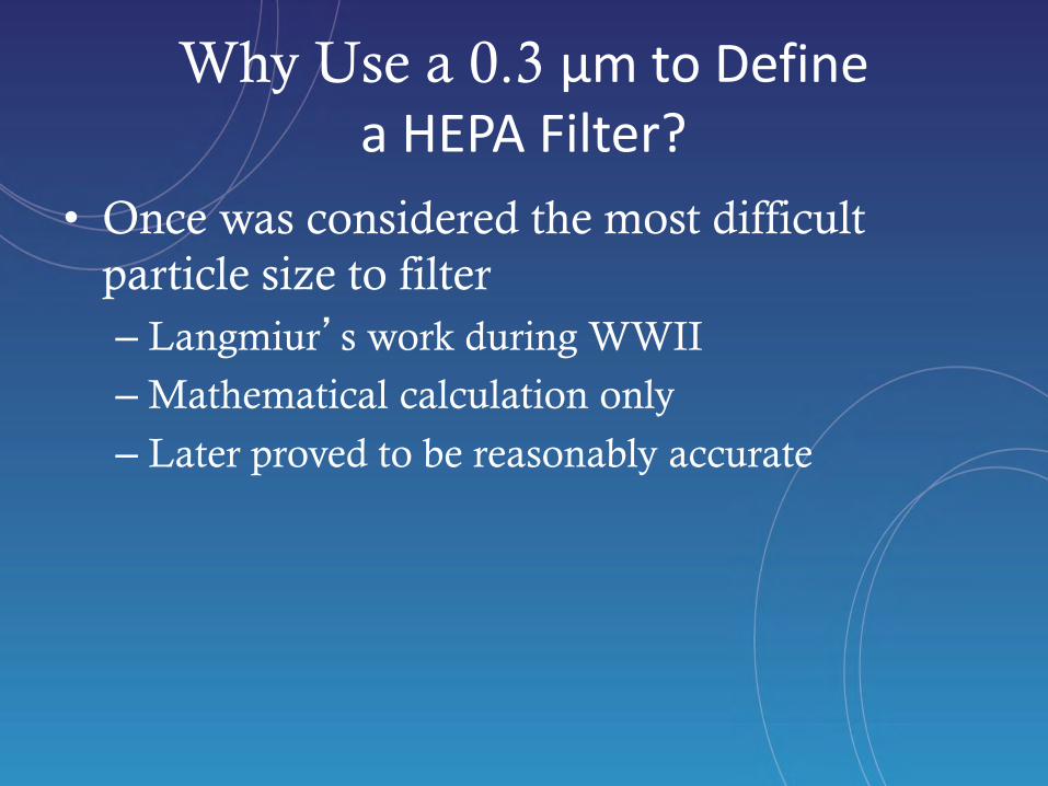
Why Use a 0.3 µm to Define a HEPA Filter?
• Once was considered the most difficult
particle size to filter
– Langmiur’s work during WWII
– Mathematical calculation only
– Later proved to be reasonably accurate

Glass Media Filtration Theory
Inertial Impaction-Particle inertia causes it to leave flow stream lines and impact on fiber
Interception-Particles with less mass stay with the airstream and impinge upon the fiber as the go around it.
Diffusion-Brownian motion/diffusion due to molecular bombardment

Relative Effect of Particle
Collection Methods

ASHRAE Grade Efficiency

HEPA Efficiency Chart
Ongoing scientific studies on nanoparticles
HEPA >99,97% efficient at
2 to 4 nanometers.
Preliminary results introduced in “Second International Symposium on Nanotechnology and Occupational Health” (Minneapolis Oct 2005)
Jean-Michel Vanhée CAMFIL FARR

Cross Section of
Dirty Glass Medium
Air Flow

Blow up of Glass Filter Medium
Air Flow

Very close view

Second Generation HEPA Filters
ePTFE Aka, Teflon, or Gore-Tex

Discovery of PTFE Discovery • Accidently discovered
by Dr. Roy Plunkett at DuPont, April 6, 1938
• Plunkett had been attempting to find a better coolant gas.
• He left a batch of tetrafluoroethylene gas in a pressure container overnight, and on returning the next day, there is a layer of white waxy solid
• The name, polytetrafluoroethlyene, was abbreviated to Teflon for simplicity and is a registered trademark
of DuPont
Material Features • Low coefficient of friction
• Outstanding temperature stability
• Outstanding electrical properties
• Outstanding chemical resistance
• Outstanding weathering and UV resistance (although PTFE can be degraded by gamma radiation dosages above 70 Mrad)
• Good toughness but generally low mechanical strength
• High specific gravity
• Translucent to opaque
• Higher cost

What is PTFE?
What gives PTFE its unique properties?
• Fluorocarbon solid – strong bonding
• High molecular weight (at least 5,000,000) – long chain
• High Melting point (327oC) – long chain
• Hydrophobic – bonding structure
• Third lowest coefficient of friction (0.05 to 0.10) against any solid – Slipperiness
• Inert to many chemicals
Chemically
• Polytetrafluoroethylene

Discovery of Expanded PTFE (ePTFE) Another Accidental Discovery • Bill Gore leaves his job at DuPont to pursue his belief in
the untapped potential of PTFE and launched W. L. Gore & Assoc. in the basement of their home in Newark, Delaware (January, 1958)
• Expanded PTFE (ePTFE) accidently discovered by Bob Gore in October, 1969
• Frustrated with rods breaking when trying to slowly stretch hot PTFE rods, he quickly draws a hot PTFE rod
• Bob finds that he can stretch PTFE 1000-times its original length
• 1st ePTFE commercial product – Teflon Pipe Tape Sealant (1970)
• Gore’s industrial filter bag business begins, and Gore is the first to use expanded PTFE for filtration, pioneering membrane surface filtration to capture contaminants and other particles (1973)
• ePTFE Gore-Tex in apparel was introduced (1976)
• First HEPA filter in 1994
PTFE-Fibrils

Process Filtration for BioTech and Pharmaceutical Applications
1. Contamination Risk Reduction – Durability and Stability
– Enhanced Air Quality (“efficiency where it matters”)
2. Energy Efficiency

Hammer Video

Glass and ePTFE HEPA Filter Media
Both images are magnified equally
Glass ePTFE

PTFE vs. Glass Media Fibers Micro-glass broken fibers at pleat tip Nelior media intact at pleat tip
Fiber Size: 450-500 nanometer (.45-.50 microns) Pore Size: 1.5-2.0 micrometer Thickness: 450-500 micrometer H13 MPPS Eff: >99.95%
Fiber Size: 50-150 nanometer (.05-.15 microns) Pore Size: 1.2-1.5 micrometer Thickness: 80-120 micrometer H13 MPPS eff: >99.95%


Low Operating Resistance
Wet laid media ePTFE media
Average pore size 3.0 µm 0.7 µm
Fiber diameter 0.5 - 1.0 µm 0.02 - 0.2 µm
Air movement effect Non slip-flow Slip-flow
ePTFE media nanometer-scale fibers and nodes
SEM photographs at 10.000x magnification:
Slip-flow air movement:
1. ePTFE media consist of fine nanometer-scale fibers
2. Scale of the fibers is small enough so that the distance
between air molecules is significant in relation to fiber size
3. Air molecules hardly collide with the fiber surface and retain
their velocities: low pressure drop
4. Because of the slip-flow phenomenon, viable particles can
travel much closer to the fiber surface so that they can get
caught easier: high efficiency
A = 50% lower pressure drop. B = 33% lower pressure drop, higher efficiency class
A
B
Comparative MPPS graphs are based on efficiency tests with flat media sheets @ airflow of 5.3 cm/s
Wet laid media fibers and binders

ePTFE Media and Theory
• Predominant filtration by interception
• Low resistance to airflow due to “slip flow” principle: Nano fibers bend air less thus lower resistance

1. Air molecules collide with the fiber surface
2. Boundary layer formed at fiber surface: Viscous flow
3. Viscous flow is causing significant pressure drop
4. Viable particles are more difficult to catch
nanofiber: ≤ 0.2 µm
1. Nano fiber is so small that most air molecules do
not collide with the fiber
2. Air molecules can easily pass the fiber: Slip-
flow.
3. Slip-flow is causing very low pressure drop.
4. Viable particles can travel much closer to the
fiber surface getting captured.
Source slip-flow air movement for nanometer-scale fibers: R.C. Brown , Air Filtration (1993)
= air molecules = viable particleS
Traditional glass
media fiber 1.0 µm
Slip Flow vs. Viscous Flow

Laminar Velocity Profiles in a Duct
Note the boundary layer

Photometer – DOP / PAO Method • Industry standard since 1960’s
– Mil Standard 282, 1956 required 80 – 100 µg DOP / L
– NSF Std 49, 1983 required > 10 µg DOP/ L
• Poly alpha olefin (PAO) replaced DOP in 1990’s
• FDA regulated facilities to test filters at least every 6 to 12 months
• Aerosol challenge of 10 - 20 µg PAO/ l of air
– 15 µg PAO/l = 20 grams PAO / 800 cfm filter / hour

Impact of Oils on Early Generation ePTFE Media

Impact of PAO on HEPA Media
0.00
0.20
0.40
0.60
0.80
1.00
1.20
0 50 100 150 200
Resi
stan
ce,
“w
c
Calculated Mass PAO (grams)
Differential Pressure vs. PAO Loading
ePTFE
PAO Sensitive
Glass Media

Modern Equipment to Test Modern Filters
• Advantages over traditional DPC testing
– User friendly
– Warns of insufficient challenge
– Warns of non uniform mixing
– Only audible beeps when Np is reached
– Reads out directly in leak as a percent of
challenge
– Provides
3-03-2014 30

Leak Detection (1 cfm or 28.3L/m)
60 rS
pDPuCpN
L
If using a 1 cfm instrument, the following formula applies
Np Number of counts that represent a potential leak during scanning Cu Upstream challenge concentration(particles/ft3) PL Local penetration % expressed as a decimal (example 0.01%=0.0001) Dp Probe dimension in the direction of scan (inches) Sr Scan rate (inches/sec) 60 Conversion: 60 seconds/min
Leak detection when scanning

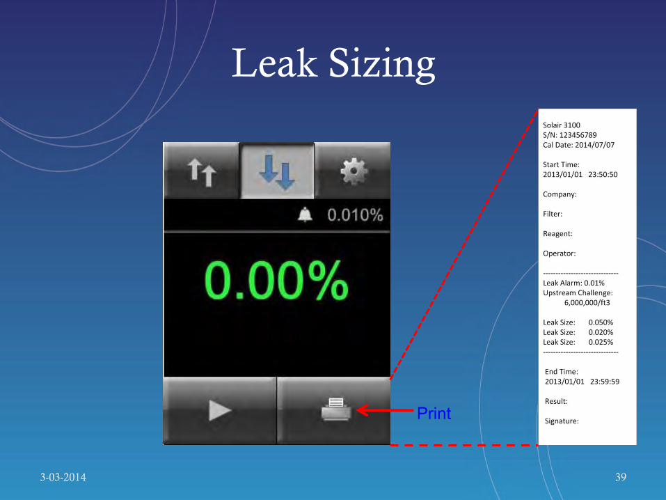
Leak Sizing (1 cfm or 28.3L/m)
PL =CdCu
If using a 1 cfm instrument, things become much more simple
PL Local penetration(leak) % expressed as a decimal (example 0.01%=0.0001) Cu Upstream challenge concentration(particles/ft3) Cd Downstream challenge concentration(particles/ft3)
Leak sizing with a stationary probe


ScanAir Pro
3-03-2014
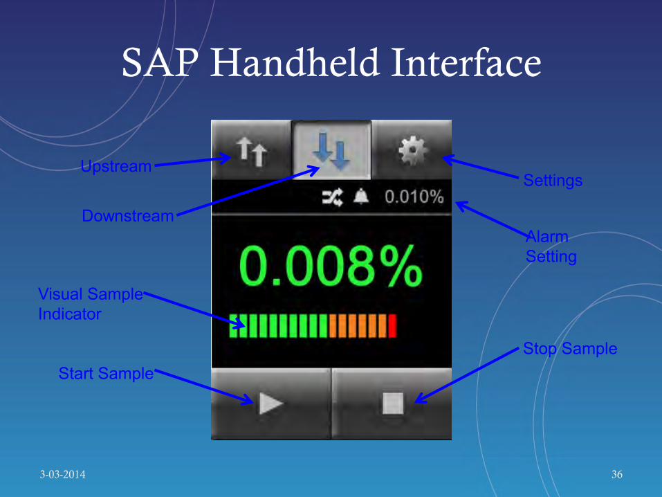
SAP Handheld Interface
3-03-2014 36
Upstream
Downstream
Settings
Stop Sample
Visual Sample Indicator
Start Sample
Alarm Setting
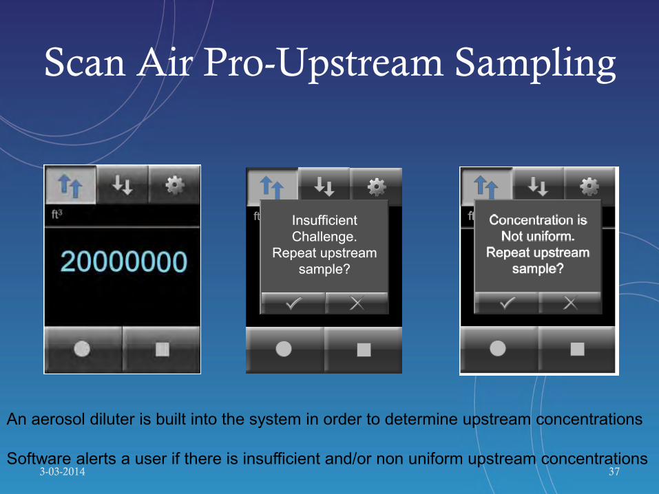
Scan Air Pro-Upstream Sampling
3-03-2014 37
1000.00
ft3 Insufficient
Challenge.
Repeat upstream
sample?
An aerosol diluter is built into the system in order to determine upstream concentrations Software alerts a user if there is insufficient and/or non uniform upstream concentrations

System Configuration
3-03-2014 38
Alarm
Scan Rate
Units
0.010%
ft3
2 "/s
Upstream Challenge
20000000 / ft3
Np 6
Mode Scan
% Significant Leak
Scan Rate inches/sec cm/sec
Units
Calculated Np
Upstream Challenge
Sample Mode Size/Scan
Leak Sizing
3-03-2014 39

Next Generation of ePTFE Oil Tolerant Filters
Exciting Advances in HEPA filters

Impact of PAO on HEPA Media
0.00
0.20
0.40
0.60
0.80
1.00
1.20
0 50 100 150 200 250 300 350 400
Resi
stan
ce,
“w
c
Calculated Mass PAO (grams)
Differential Pressure vs. PAO Loading
ePTFE – PAO Tolerant ePTFE
PAO Sensitive
Glass Media

Filter Life Comparison PTFE vs. Glass Filter

Filter Life Comparison PTFE vs. Glass Fiber
0
100
200
300
400
500
600
0 30 60 90 120 150 180
経過日数(日)
圧力損失(Pa)
Conventional PTFE(with pre/middle range filter)
Commercial fiberglass(with pre filter)
New fluororesin(with pre filter)
New fluororesin(with pre/middle range filter)
Test period (day)
Press
ure d
ro
p (
Pa
)
0
100
200
300
400
500
600
0 30 60 90 120 150 180
経過日数(日)
圧力損失(Pa)
0
100
200
300
400
500
600
0 30 60 90 120 150 180
経過日数(日)
圧力損失(Pa)
Conventional PTFE(with pre/middle range filter)
Commercial fiberglass(with pre filter)
New fluororesin(with pre filter)
New fluororesin(with pre/middle range filter)
Test period (day)
Press
ure d
ro
p (
Pa
)

Impact of PAO on HEPA Media
0.00
0.20
0.40
0.60
0.80
1.00
1.20
0 50 100 150 200 250 300 350 400
Resi
stan
ce,
“w
c
Calculated Mass PAO (grams)
Differential Pressure vs. PAO Loading
ePTFE – PAO Resistant ePTFE
PAO Sensitive
Glass Media
3-03-2014 NEBB CPT Technician Training 44
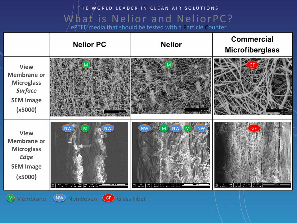
What i s Nel ior and Nel iorPC? ePTFE media that should be tested with a Particle Counter
T H E W O R L D L E A D E R I N C L E A N A I R S O L U T I O N S
Nelior PC Nelior Commercial
Microfiberglass
View Membrane or
Microglass Surface
SEM Image
(x5000)
View Membrane or
Microglass Edge
SEM Image
(x5000)
e
M M M
M M GF
GF NW NW NW NW NW
M NW GF Membrane Nonwoven Glass Fiber
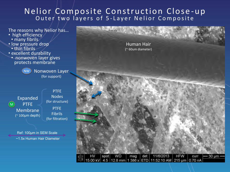
Nel ior Compos i te Construct ion C lose -up O u t e r t w o l a y e r s o f 5 - L a y e r N e l i o r C o m p o s i t e
M
NW
Expanded PTFE
Membrane (~ 100μm depth)
Nonwoven Layer (for support)
Human Hair (~ 60um diameter)
PTFE Nodes
(for structure)
PTFE Fibrils
(for filtration)
The reasons why Nelior has… • high efficiency
• many fibrils • low pressure drop
• thin fibrils • excellent durability
• nonwoven layer gives protects membrane
Ref: 100μm in SEM Scale ~1.5x Human Hair Diameter

Comparison of PAO Challenge Concentration Ranges
0.01
0.1
1
10
100
Aer
oso
l Co
nce
ntr
atio
n µ
g/l
Particle Counter Photometer
~0.03 – 0.3 µg/l
~10-40 µg/l
Microglass ePTFE (oil-sensitive) ePTFE (oil-tolerant)
Microglass ePTFE (oil-tolerant)
ePTFE (oil-sensitive)

Summary
• Glass media has been around for 75 years
– Fragile but oil tolerant
– Good dust holding capacity
• Early ePTFE media since 1994
– Very durable
– Not tolerant of oil challenge aerosols
– Limited dust holding capacity
– Less than 50% of the resistance of glass

Summary
• Latest generation of ePTFE
– Very durable
– Over twice the oil holding capacity of glass media
– Dust holding capacity exceeds glass
– Approximately 50% lower resistance than glass

Questions?
3-03-2014 50