Embed Size (px)
Citation preview

QUICK START DESIGN MANUAL (SPATE DIVERSION WORKS)
PREPARED BY
MR. MANOHAR SINGH
IRRIGATION ENGINEERING CONSULTANT

QUICK START DESIGN MANUAL FOR SPATE DIVERSION WORKS Page 2 of 28
DESIGN MANUAL

QUICK START DESIGN MANUAL FOR SPATE DIVERSION WORKS Page 3 of 28
CONTENTS

QUICK START DESIGN MANUAL FOR SPATE DIVERSION WORKS Page 4 of 28
QUICK START DESIGN MANUAL
(SPATE DIVERSION WORKS)
CONTENTS
SECTION DESCRIPTION PAGE
1.0 INTRODUCTION 1 OF 24
2.0 PLANNING ASPECTS/DESIGN CONCEPT 2 OF 24
3.0 STEPS TO BE TAKEN AT THE PRE DESIGN STAGE 2 OF 24
4.0 STEPS TO BE TAKEN AT THE DESIGN STAGE 4 OF 24
5.0 DESIGN OF VARIOUS COMPONENTS 6 OF 24
6.0 TOTAL SAFE DISCHARGING CAPACITY OF THE SPATE DIVERSION WORKS 15 OF 24
7.0 BANK PROTECTIONS 15 OF 24
8.0 DESIGN OF CANAL(S) 16 OF 24
ANNEXES
NO. TITLE
I DATA FOR ECONOMICAL DESIGN OF EARTHEN CANALS
II UPLIFT FORCES AND THICKNESS OF STILLING BASINS
III DESIGN OF UPSTREAM AND DOWNSTREAM PROTECTIONS FOR DIFFERENT COMPONENTS
IV BLENCH CURVES
V ENERGY OF FLOW CURVES
VI NORMAL DEPTH OF SCOUR V/S UNIT DISCHARGE
VII NORMAL DEPTH OF SCOUR V/S DISCHARGE

QUICK START DESIGN MANUAL FOR SPATE DIVERSION WORKS Page 5 of 28
QUICK START DESIGN MANUAL (SPATE DIVERSION WORKS)
1.0 INTRODUCTION
This Quick Start Design Manual, covers the Steps required to do design of Spate Diversion
Works and was primarily prepared by the author for refreshing the Yemeni Engineers
involved in the field of development of Spate Works. This manual was prepared by the
author while he was engaged in Groundwater and Soil Conservation Project that was
funded by the World Bank.
To make it adaptable by the Yemeni Engineers, during the course of preparation of this
Design Manual, attempt has been to make it as simple as possible but without
compromising and/or loosing the technical contents and the resulting outputs.
The guidance and cooperation received from all those, especially Mr. Hamoud Rubaidi,
Project Director, Groundwater and Soil Conservation Project and Mr. KS Sharma, Irrigation
Engineering Advisor, GSCP in accomplishing the task of preparation of this Quick Start
Design Manual is thankfully acknowledged.
Any suggestions to improve this manual are welcome and shall be thankfully
acknowledged by the author (Manohar Singh: [email protected])
2.0 PLANNING ASPECTS & DESIGN CONCEPT
It is expected that the Planning Aspects and the details of the Design Concept in respect
of various components of the Spate Diversion Works are known to the engineers for whom
it is intended.
3.0 STEPS TO BE TAKEN AT THE PRE DESIGN STAGE
3.1 STEP – I: RECONNAISSANCE VISIT TO SITE
Make a reconnaissance visit to the proposed site of the Spate Diversion Works to have a
feel of the site conditions. During this site visit meet the concerned beneficiaries to know
their views about the past and present site conditions and any specific requirements.
Some of the relevant available information as listed under the following paragraphs may
also be collected during this visit.
3.2 STEP – II: COLLECTION OF SITE INFORMATION
(i) Location of Site: Name of Wadi, District, Governorate, Nearest City, Nearest Village,
Name of Major Road, Coordinates and Index Map;
(ii) Weir Axis: Note down the location of the weir axis in case the beneficiaries are already
having some temporary means of diverting the water.
(iii) Description of Site: During the reconnaissance visit take notes about the wadi bed
conditions, location of canal(s), canal bed conditions, maximum observed water level
as may be seen on the wadi banks, type of material in wadi and the canal(s) and any
other existing feature;
(iv) Command Area: The area(s) under command of the various canal(s) and their
location vis-à-vis the location of diversion works;

QUICK START DESIGN MANUAL FOR SPATE DIVERSION WORKS Page 6 of 28
(v) Type of Crops: Type of crops being grown in the command area and percent of area
under each of the crops and the corresponding yield of each crop;
(vi) Number of Spates per crop season;
(vii) Duration of each spate; and
(viii) Depth of application of water in the fields.
3.3 STEP – III: COLLECTION OF HYDROLOGICAL INFORMATION
Collect the Hydrological Report containing the Catchment Area, Rainfall Data, Location
of Rain Gauges in the Catchment Area and Maximum Floods for the 5, 10, 25 and 50 years
flood frequencies as follows:
RETURN PERIOD DISCHARGE
IN CUMECS USAGE
5 Years For Design of less important
structures In cases where in the
event of failure of the
structure, loss to life
and property is
minimum
10 Years For Design of Wadi Bank
Protections
25 or 30 Years For design of Canal Control
Structures
50 Years For design of Medium size Spate
Diversion Works
In cases where in the
event of failure of the
structure, loss to life
and property is
appreciable
3.4 STEP – IV: COLLECTION OF TOPOGRAPHICAL SURVEY MAPS
S. NO. DESCRIPTION SCALES REMARKS
(i)
A plan showing the contour map of the site having a
contour interval of 0.25 or 0.50 m for a reach of about 500
m covering the area of interest. This plan in addition to the
wadi banks should also show all the existing features & if
there is some temporary diversion structure made by the
beneficiaries along with the existing Canal(s).
1:500
THESE SC
ALE
S A
RE O
NLY
FO
R G
UID
AN
CE
AN
D
IF
NEC
ESSA
RY
THESE
SH
ALL
B
E
MO
DIF
IED
TO
SU
ITE
A
PA
RTI
CU
LAR
SIT
E
CO
ND
ION
(ii) Longitudinal profile of the wadi for the above said length. H = 1:1000
V = 1:100
(iii)
Cross Sections of wadi at minimum 7 locations: 1 Cross
Section at the proposed Weir Axis, 3 Cross Sections in the
upstream and 3 Cross Sections in the downstream.
H = 1:100
V = 1:100
(iv) Longitudinal profile of the Canal(s) for lengths up to 500 m
or more.
H = 1:2000
V = 1:100
(v) Cross Sections of the Canal(s) at 50 m each. H = 1:100
V = 1:100
(vi) A map showing the Work Site, Wadi, Canals and
Command Area(s). 1:10,000
3.5 STEP – V: COLLECT DESIGN PARAMETERS RELATED TO SOILS TYPE BASED ON SITE
INVESTIGATIONS
Based upon Site Investigations or on the basis of Reconnaissance Visit adopt the Design
Parameters related to soil type and wadi bed or Canal bed materials from the Standard
Values given in the table below:

QUICK START DESIGN MANUAL FOR SPATE DIVERSION WORKS Page 7 of 28
ADOPTED VALUES OF VALUES OF LACEY’S SILT FACTOR ‘f' AND MANNING'S ‘n’
DESIGN PARAMETERS FOR STRUCTURES IN WADI FOR STRUCTURES IN CANAL
LACEY’S SILT FACTOR “f” ADOPT FROM THE ABOVE TABLE ADOPT FROM THE ABOVE TABLE
MANNING'S "n" ADOPT FROM THE ABOVE TABLE ADOPT FROM THE ABOVE TABLE
STANDARD VALUES OF LACEY’S SILT FACTOR ‘f' AND MANNING'S ‘n’
TYPE OF MATERIAL GRAIN SIZE (mm) SILT FACTOR (f) MANNING'S (n)
SILT
Very Fine 0.052 0.4 0.0179
Fine 0.120 0.6 0.0198
Medium 0.158 0.8 0.0210
Standard 0.323 1.0 0.0225
SAND
Medium 0.505 1.25 0.0230
Coarse 0.725 1.5 0.0249
Heavy 1.200 2.0 0.0267
Gravely 2.5 – 7.0 3 – 4 0.0312
GRAVEL Medium 7.28 5 0.030
Heavy 26.10 8 – 10 0.039
BOULDERS Medium 72.50 15 0.044
Large 183.80 20 0.050
3.6 STEP – VI: PLAN COMPONENTS OF THE SCHEME
Plan the components as required for the specific site under consideration. Normally a
Spate Diversion Work comprises the following components:
A Permanent Stone Masonry Diversion Weir;
A Fuse Plug in combination with the Stone Masonry Weir in case of very wide
wadis for economizing the cost of the Spate Diversion Works;
Gated Canal Intake(s) for the canals;
Gated Silt Sluice(s)for each of the Canal(s) ;
Wing Walls and Divide Walls;
Stone Rip Rap Aprons in the upstream and downstream of the weir;
Rehabilitation of the existing portions of the canal and construction of parts of
the canal wherever necessary; and
Some Wadi Bank Protections on the wadi bank(s) in the upstream of the Spate
Diversion Works to protect the agricultural lands or other properties from the HFL;
4.0 STEPS TO BE TAKEN AT THE DESIGN STAGE
4.1 STEP – VII: SELECTION OF WEIR AXIS
In Case of an Existing Temporary Diversion Structure Requiring Rehabilitation: In most cases
in Yemen beneficiaries have already built traditional diversion structures on most wadis
and had been doing irrigation for decades. This is normally based on their long and tried
experience. In such cases it is always desirable to select the same axis of the weir as being
used by the beneficiaries.
In Case of Newly Planned Diversion Structure: In order to arrive at a design that is techno-
economically most viable, it is normal practice to examine alternative sites for locating the
axis of the weir. Accordingly, in such cases more than one alternative should be
examined. The merits and demerits of the various alternatives should be discussed in the
Design Report.

QUICK START DESIGN MANUAL FOR SPATE DIVERSION WORKS Page 8 of 28
4.2 STEP – VIII: WADI STAGE-DISCHARGE AND RATING CURVES
Using FLOWMASTER work out the Wadi Stage-Discharge and Rating Curves at a wadi Cross
Section where the weir axis is proposed to be located.
4.3 STEP – IX: DESIGN PARAMETERS FOR THE CANAL INTAKE
Normal - USWL = Same as Crest Level of the Weir (This is the USWL at which the canal
intake should be able to pass the design discharge in to the canal, before water starts
spilling over the Weir)
Maximum Pond Level - USWL = Same as maximum Pond Level including the flood lift
due to weir construction
FSD (DSWL) = Full Supply Depth in the Canal (See Annex - I)
Sill Level of Canal Intake = Wadi Bed Level in front of the Canal Intake + 0.25 to 0.50 m
Canal Design Discharge: Determine the Canal Design Discharge using the following
formulae:
Q = (2.77 x A x W)/(E x N)
Where Q = Canal Discharge in Cumecs;
A = Net Command Area in Ha;
W = Average Irrigation Application Depth in m;
E = Overall Irrigation Efficiency with improved works; and
N = Average Number of Hours Wadi Flow is available.
DESIGN DISCHARGE IN THE CANAL
S. NO. ITEM VALUES REMARKS
i Gross Command Area (GCA) Ha
ii
Culturable Command Area (CCA)
i.e. Command area net of field bunds
& pathways etc.
Ha
90 % of GCA. (Assuming 10 % area to
be occupied by field channels,
pathways & distribution system etc.)
iii Command area irrigable at low
spates (CIL) 20 %
To be assumed on the basis of
discussions with beneficiaries.
iv Net command area (A) Ha About 70 % of the GCA
v Depth of water application (W) m To be adopted on the basis of
discussions with beneficiaries. Vii Average number of hours wadi flow is
normally available in each spate (N) Hrs
vii Overall irrigation efficiency (E) 0.46
Source: Land & Water Conservation
Project (LWCP), Preparation Mission
Report of 1991.
viii Discharge (Q) In the Canal at the
Intake Point
Cumecs
Formula for determining discharge:
Q = 2.77 x A x W / (E x N)
4.4 STEP – X: DESIGN PARAMETERS FOR THE SILT SLUICE
Discharge (Q) = Assume about 50 % of the discharge through Canal Intake
USWL = Same as maximum Pond Level including the flood lift due to weir construction
DSWL = Water level in the wadi at Design Discharge (Q50) of the Weir
Sill Level of Silt Sluice = Same as Wadi Bed Level in front of the Silt Sluice
4.5 STEP – XI: DESIGN PARAMETERS FOR THE OVER FLOW WEIR
Discharge (Q) = Wadi Flow at 30 years or 50 Years Return Period
USWL = Same as maximum Pond Level including the flood lift due to weir construction
DSWL = Water level in the wadi at Design Discharge (Q30 or Q50) of the Weir
Weir Crest = Canal Intake Level + Canal FSD + HL (Assume about 0.15 to 0.20 m)
Apron Level in the upstream of the Weir = Average Wadi Bed Level in front of Weir

QUICK START DESIGN MANUAL FOR SPATE DIVERSION WORKS Page 9 of 28
4.6 STEP – XII: Upstream & Downstream Water Levels
Determine the downstream water levels in the wadi for the different discharges from the
Rating Curve and Wadi Stage-Discharge Curves. Adopt the Upstream Water Levels
keeping in view the required FSL in the canal, required weir crest & also the observed HFLs
in the wadi and the anticipated flood lift in the upstream due to construction of the
overflow weir. The upstream & downstream water levels so determined should be
presented in the following table:
RETURN PERIOD DISCHARGE
(Cumecs)
UPSTREAM HFLs
(m)
DOWNSTREAM
HFL (m)
5 years
10 years
25 or 30 years
50 years
REMARKS
5.0 DESIGN OF VARIOUS COMPONENTS
5.1 STEP – XIII: DESIGN OF SILT SLUICE
5.1.1 Design of Silt Sluice Length of Water Way (Opening)
Since the Silt Sluice(s) are gated & proposed to be provided with breast walls, submerged
orifice formulae will be used to design these structures as explained in the conceptual
diagram below:
CONCEPTUAL DIAGRAM OF SILT SLUICE

QUICK START DESIGN MANUAL FOR SPATE DIVERSION WORKS Page 10 of 28
The formula for discharge through submerged orifice is given by
Q =
Cd x A x √
In the above formulae we have
Q = Discharge through the silt sluice in Cumecs (m3/sec)
L = Clear length of water way (m)
Cd = Coefficient of discharge having a value of 0.62
A = Area of opening of the silt sluice / Canal Intake (orifice) in m2
g = Acceleration due to gravity (9.81 m/sec2)
H = Effective head over the crest (USWL – DSWL) or (USWL – FSL) in m
5.1.2 Design of Upstream and Downstream Aprons/Protections and Stilling Basin:
Design these appurtenant works as per details given in Annex - III
5.1.3 Design of RCC Breast Wall and Platforms
Design the RCC Breast Walls for the horizontal water pressure from the upstream and
dead load. And design the RCC platforms for the Live Load and Dead Load
5.1.4 Design of Radial Gates, Hoisting Arrangements & Hoisting Platform
The design of Vertical Steel Gates & Hoisting Arrangements shall be supplied by the Gate
Manufacturer. Or try to use gates having standard size which are readily available in the
market.
5.2 STEP – XIV: DESIGN OF GATED CANAL INTAKE
5.2.1 General
As per the criteria for design of spate diversion works, the canal intake should be able to
pass the design discharge in to the canal, before water starts spilling over the Weir. The
discharge in the canal, when the upstream water level is at HFL would be higher than the
full supply discharge of the canal. But this event would be very rare and in such situations
to prevent and/or to minimize damage to the canal, the excess flow of water in the canals
shall be controlled by operation of the Canal Intake gates.
If topography permits a suitable Canal Escape can also be provided either in the
upstream or downstream of the Canal Intake. The crest of such an escape shall be kept at
the canal FSL. The length of escape shall be designed to account for the surplus discharge
likely to enter the canal.
The sill level of the Canal Intake shall be provided at a level which is higher than the wadi
bed level by about 0.25 to 0.50 m, so that entry of silt in to the canal is prevented or
minimized.
5.2.2 Clear Width of the Intake when the Sill is Submerged and the Upstream Water Level is
Between the Sill and the Bottom of Breast Wall
When the USWL level is same as the crest level of the weir/bottom level of the breast wall,
it should be possible to pass the design discharge of the Canal, so that the required
discharge in the canal is available before the water starts overflowing the weir back in to
the wadi.

QUICK START DESIGN MANUAL FOR SPATE DIVERSION WORKS Page 11 of 28
The conceptual diagram showing the formation of profile of flow is given below:
CONCEPTUAL DIAGRAM OF CANAL INTAKE
Drowned Weir Formula neglecting the head due to velocity of approach, shall be used for
determining the length of water way and/or for discharge calculations. This formula is
given below :
Q = 2/3 x C1 x L x √ x H3/2 + C2 x d x L x √
In the above formulae we have
Q = Discharge in Cumecs (m3/sec)
L = Clear length of water way (m)
C1 = Numerical coefficient (Assumed value = 0.577)
C2 = Numerical coefficient (Assumed value = 0.80 )
g = Acceleration due to gravity (9.81 m/sec2 )
H = Difference of upstream & downstream water levels (m)
d = Depth of downstream water level above the crest (m)
After determining the length of the Canal Intake provide the number of bays in such a
manner that the width of the Steel Vertical Gate is not more than 2 m from the
consideration of the operation and maintenance of the Gates.
5.2.3 Discharge Over the Canal Intake when the Upstream Pool Level is above the Bottom
Level of the Breast Wall
Discharging capacity of the canal intake at the upstream pond level shall, however, be
more than that worked out in the previous Paragraph. The water level (FSL) in the canal
shall also rise in that event. Since the canal intake shall be gated & provided with breast
wall, the discharging capacity shall be worked out using the drowned orifice formulae.

QUICK START DESIGN MANUAL FOR SPATE DIVERSION WORKS Page 12 of 28
The conceptual diagram showing the formation of profile of flow through submerged
orifice is given below:
CONCEPTUAL DIAGRAM OF CANAL INTAKE
The formula for discharge through submerged orifice is given by
Q = Cd x A x √
In the above formulae we have
Q = Discharge through the Canal Intake in Cumecs (m3/sec)
L = Clear length of Canal Intake (m)
Cd = Coefficient of discharge having a value of 0.62
A = Area of opening of the Canal Intake (orifice) in m2
g = Acceleration due to gravity (9.81 m/sec2)
H = Effective head over the crest (USWL – DSWL) or (USWL – FSL) in m
Since the required design discharge and also the FSD in the canal would be available, as
soon as the pond level reaches the weir crest level and as most of the times wadi is
expected to have low discharges, the excess discharge in the canal on account of rise in
water level beyond the crest level shall be controlled by means of operation of Canal
Intake gates to prevent damage to the canal. In certain cases where Canal Escape can
be provided, the crest level shall be kept at the Canal FSL.
5.2.4 Design of Upstream and Downstream Aprons/Protections and Stilling Basin:
Design these appurtenant works as per details given in Annex - III
5.2.5 Design of RCC Breast Wall and Platforms
Design the RCC Breast Walls for the horizontal water pressure from the upstream and
dead load. And design the RCC platforms for the Live Load and Dead Load
5.2.6 Design of Radial Gates, Hoisting Arrangements & Hoisting Platform
The design of Vertical Steel Gates & Hoisting Arrangements shall be supplied by the Gate
Manufacturer. Or try to use gates having standard size which are readily available in the
market.

QUICK START DESIGN MANUAL FOR SPATE DIVERSION WORKS Page 13 of 28
5.2.7 Design of Ungated Canal Intake
In situations, where due to economical reasons it is not possible to provide gates, the
Canal Intake can be designed as ungated. Breast Wall shall also not be required in such
cases.
The clear width of the Canal Intake shall be designed in the same manner as given in
paragraph 5.2.2 of this Manual.
But to prevent damage to the canal under higher floods, it would be essential to provide a
Canal Escape either in the upstream or the downstream of the Canal Intake depending
upon the Topography. The crest of such an escape shall be kept at the canal FSL. The
length of escape shall be designed to account for the surplus discharge likely to enter the
canal.
The sill level of the Canal Intake shall be provided at a level which is higher than the wadi
bed level by about 0.25 to 0.50 m, so that entry of silt in to the canal is prevented or
minimized.
5.3 STEP – XV: DESIGN OF MASONRY OVERFLOW WEIR
5.3.1 Length of the Weir When the Weir Crest is Submerged
In this condition the downstream water level (DSWL) is above the weir crest and the
Drowned Weir Formula neglecting the head due to velocity of approach, shall be used for
determining the length of water way and/or for discharge calculations. This formula is
given below along with the conceptual sketch:
Q = 2/3 x C1 x L x √ x H3/2 + C2 x d x L x √
In the above formulae we have
Q = Discharge in Cumecs (m3/sec)
L = Clear length of water way (m)
C1 = Numerical coefficient (Assumed value = 0.577)
C2 = Numerical coefficient (Assumed value = 0.80 )
g = acceleration due to gravity (9.81 m/sec2 )
H = Difference of upstream & downstream water levels (m)
d = Depth of downstream water level above the crest (m)
CONCEPTUAL DIAGRAM OF MASONRY OVERFLOW WEIR

QUICK START DESIGN MANUAL FOR SPATE DIVERSION WORKS Page 14 of 28
5.3.2 Length of the Weir When the Crest is not Fully Submerged
In this condition the downstream water level (DSWL) is below the weir crest level and Free
Fall Formulae shall be used. When the DSWL is below the crest level, we have d = 0 in the
formulae under drowned condition given in the above paragraph.
Q = 2/3 x C1 x L x √ 2 g x H3/2
In the aforesaid formulae we have
Q = Discharge in Cumecs (m3/sec)
L = Clear length of water way (m)
C1 = Numerical coefficient (Assumed value = 0.577)
g = acceleration due to gravity (9.81 m/sec2 )
H = Difference of upstream water level and the weir crest (m)
Substituting the values of C1 & g in the above formulae, we get
Q = 1.7 x L x H3/2
or
Q = Cd x L x H3/2 (Cd : Discharge Coefficient = 1.7)
The conceptual diagram showing various parameters is presented below:
CONCEPTUAL DIAGRAM OF MASONRY OVERFLOW WEIR
5.3.3 Design of Upstream and Downstream Aprons/Protections and Stilling Basin:
Design these appurtenant works as per details given in Annex - III
5.3.4 Energy Dissipation & Stilling Basin
In accordance with what has been stated in (Annex – I) the upstream & downstream
protection works and/or aprons are proposed to be made from gabions. Below these
gabions filter fabric of suitable specifications shall be provided. Further to above and in
order to prevent any clogging of the synthetic filter fabric, 20 cm thick graded sand-gravel
mixture between the formation level and the filter cloth under the gabion cistern shall also
be provided.
QUICK START DESIGN MANUAL FOR SPATE DIVERSION WORKS Page 15 of 28
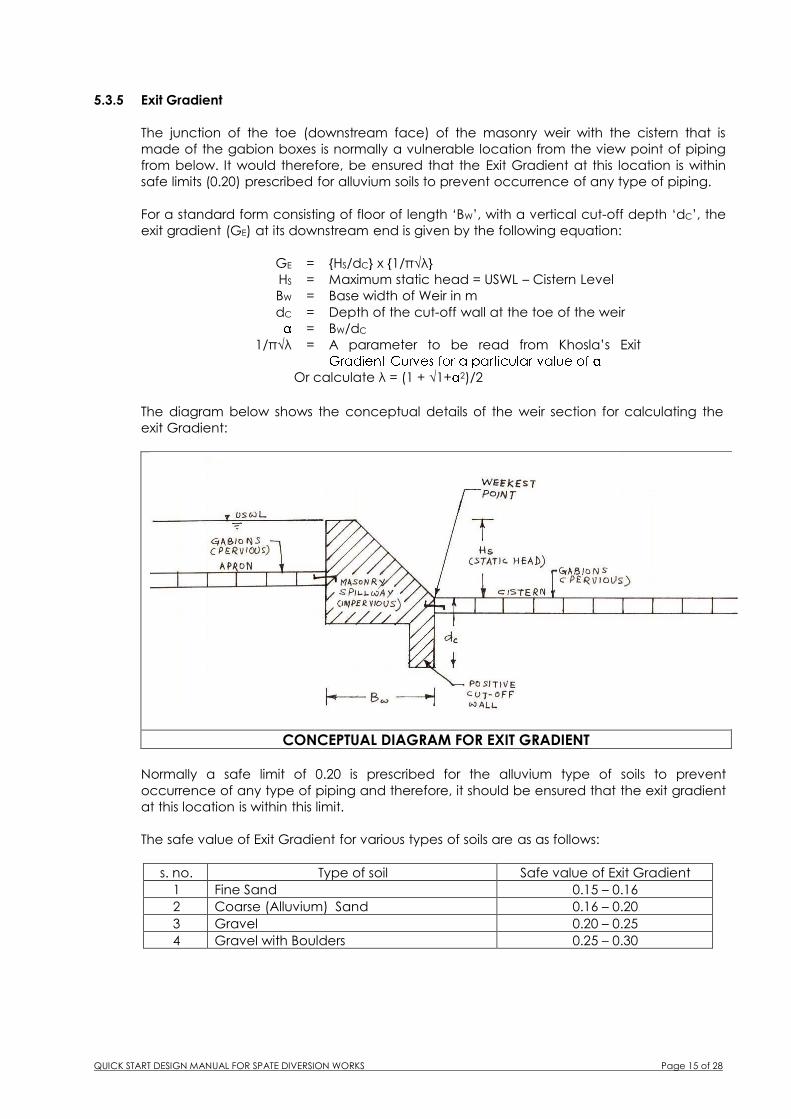
5.3.5 Exit Gradient
The junction of the toe (downstream face) of the masonry weir with the cistern that is
made of the gabion boxes is normally a vulnerable location from the view point of piping
from below. It would therefore, be ensured that the Exit Gradient at this location is within
safe limits (0.20) prescribed for alluvium soils to prevent occurrence of any type of piping.
For a standard form consisting of floor of length ‘BW’, with a vertical cut-off depth ‘dC’, the
exit gradient (GE) at its downstream end is given by the following equation:
GE = {HS/dC} x {1/π√λ}
HS = Maximum static head = USWL – Cistern Level
BW = Base width of Weir in m
dC = Depth of the cut-off wall at the toe of the weir
= BW/dC
1/π√λ = A parameter to be read from Khosla’s Exit
Or calculate λ = (1 + √1+ 2)/2
The diagram below shows the conceptual details of the weir section for calculating the
exit Gradient:
CONCEPTUAL DIAGRAM FOR EXIT GRADIENT
Normally a safe limit of 0.20 is prescribed for the alluvium type of soils to prevent
occurrence of any type of piping and therefore, it should be ensured that the exit gradient
at this location is within this limit.
The safe value of Exit Gradient for various types of soils are as as follows:
s. no. Type of soil Safe value of Exit Gradient
1 Fine Sand 0.15 – 0.16
2 Coarse (Alluvium) Sand 0.16 – 0.20
3 Gravel 0.20 – 0.25
4 Gravel with Boulders 0.25 – 0.30

QUICK START DESIGN MANUAL FOR SPATE DIVERSION WORKS Page 16 of 28
5.3.6 Design of Section of Masonry Weir
Top Width of the Weir: Top width of the weir on the consideration of elementary profile
(stress criterion) of the weir is given by the following formula:
Tw = d/ö in m
Where Tw = Top width of weir in m
d = USWL – Weir Crest Level
∂ = Unit weight of masonry in T/m3
Top width of the weir on the consideration of safety of the weir against sliding is given by
the following formula:
Tw = d /µ ∂
Where Tw = Top width of weir in m
d = USWL – Weir Crest Level
∂ = Unit weight of masonry in T/m3
And µ = Coefficient of friction
The maximum of the two values of TW obtained from the above said two considerations
should be adopted subject to a minimum of 1.0 m
Bottom Level of the Weir: Bottom level of the weir shall be decided from the following two
considerations:
(i) Scour and (ii) Bottom level of the Stilling Basin Floor
Adopt the bottom level of the weir at a level which is lower of the two levels obtained
from the above considerations. And accordingly, the stability of the weir wall should be
also be checked at this level.
Stability Analysis of the Weir Section: Check the stability of the weir for the following
loading conditions:
Self-Load of the Masonry Weir;
Upstream Water Pressure when the Water Level is at HFL;
Downstream Water Pressure when the Water Level is at DSWL;
Uplift Forces at the Bottom of the weir;
Weight of the Water Column on the top and Downstream Slope of the Weir; and
Earth Pressure on the upstream face of the weir as it would be silted after few spates.
CONCEPTUAL DIAGRAM FOR STABILITY ANALYSES OF MASONRY OVERFLOW WEIR

QUICK START DESIGN MANUAL FOR SPATE DIVERSION WORKS Page 17 of 28
5.3.7 RCC Coping on the Weir Top
To prevent any damage that might be caused due to continuously flowing water to the
top surface of the weir that is made of stone masonry, RCC (1:2:4) Coping 300 mm thick
suitably anchored to the top should be provided.
5.4 STEP – XVI: DESIGN OF DIVIDE WALLS/WING WALLS
5.4.1 General
In order to divide the varied nature of flow between Overflow Weir portion and the Silt
Sluice, suitable Divide Walls shall be provided between Canal Intake, Silt Sluice and the
Overflow Weir. Similarly, suitable Wing Walls with Weep Holes shall be provided at the left
and right banks of the wadi.
The Wing Wall shall be designed as Retaining Walls as these have to retain earth on one
side. The wing walls shall be provided with suitable drainage arrangements to drain off the
water and thus reduce hydrostatic pressure at the back of the wall. Commonly used
drainage system is to provide weep holes, wherever necessary to release the excess
pressure from the soil behind the wing walls.
The worst loading combination shall be when there is no water in the wadi and wet soil on
the back of the Wing Walls. Accordingly the Wing Walls shall be designed as Gravity
Structure to resist the following forces:
Self-Load of the Wing Walls;
Weight of the backfill on the back of the Wing Walls; and
Horizontal Pressure from the backfill considering it as Saturated Soil;
5.4.2 Scour Depth/Bottom Level of the Wing Walls
The bottom level of the Wing Walls shall be determined from the consideration of
maximum scour as follows:
The standard depth of scour in a wadi is given by the following formula:
R = 0.475 (Q/f)1/3
Where R = Standard depth of scour (m) below wadi HFL;
Q = Maximum Design Discharge (Cumecs);
f = Silt factor.
The recommended depth of scour is usually taken as follows:
5.4.3 Design Parameters
Foundation level = m
Top level of wing wall = m
D/S Slope Level = m
U/S Slope (H/V) =
D/S Slope (H/V) =
Top width of wing wall = m
Angle of internal friction (Φ) = Degrees
Unit weight of Masonry = Ton/m3
Unit weight of wet earth = Ton/m3
Bearing Capacity of soil = Ton/m2
Maximum allowable compressive stress in masonry = Ton/m2
Coefficient of friction (µ) =

QUICK START DESIGN MANUAL FOR SPATE DIVERSION WORKS Page 18 of 28
5.4.4 Weep Holes
As mentioned before the wing walls shall be designed as Retaining Walls as these have to
retain earth on one side. The wing walls shall be provided with suitable drainage
arrangements to drain off the water and thus reduce hydrostatic pressure at the back of
the wall. Commonly used drainage system is to provide weep holes, as shown in the
diagram below.
CONCEPTUAL DIAGRAM FOR WEEP HOLES IN WING WALL
The weep holes shall consist of PVC pipes of 75 mm diameter and shall be spaced about
2.0 m center to center both horizontally (staggered) and vertically. The lower most line of
the weep holes shall be placed at a height of 300 mm from the bed of the wadi at that
location. The weep holes shall be prevented from clogging and loss of soil from the backfill
by two layers of filter cloth. These filter clothes on the end of the weep hole pipe shall be
covered by selected granular soil.
6.0 Step – XVII: TOTAL SAFE DISCHARGING CAPACITY OF THE SPATE DIVERSION WORKS
The total safe discharging capacity of the Spate Diversion Works as a whole shall be
determined as follows :
QTA = QO + QS + QC + QE
QTB = QO + QE
here QTA = Total safe discharging capacity of the Spate Diversion
Works as a whole, in the event when Silt Sluice and Canal
Intake Gates are opened and the Canal Escape also is
functional; and
and QTB = Total safe discharging capacity of the Spate Diversion
Works as a whole, In the event when Silt Sluice gate and
Canal Intake Gate is closed but Canal Escape is
functional.
The total safe discharging capacity of the Spate Diversion Works as a whole shall not be
less than the maximum design discharge.

QUICK START DESIGN MANUAL FOR SPATE DIVERSION WORKS Page 19 of 28
7.0 STEP – XVIII: DESIGN OF BANK PROTECTIONS
As mentioned before, wherever necessary wadi banks and adjoining lands in the vicinity
of the Spate Diversion Works shall be suitably protected up to the maximum upstream
pond level that is likely to occur. The Wadi Bank Protections therefore, shall be provided
and designed accordingly.
8.0 STEP – XIX: DESIGN OF CANAL(S)
Design Parameters: The canal shall have the following design parameters,
Q (Discharge) in m3/s = Known
d (Depth of water - FSD) in m = Known
BB (Internal Base Width) in m = To be Determined
H:V (Side Slopes) = Adopt as 1:1 or depending on site conditions
A (Area of flow) m2 = [(BB + BW)/2] x d
P (Wetted Parameter) in m = BB + 2 {√2 d2}
R (Hydraulic Mean Radius) in m = A/P
S (Canal Bed Slope) = Adopt from Annex - I
N (Manning’s ‘n’) = Adopt from Table given on page 3 of 23
CONCEPTUAL DIAGRAM OF CANAL CROSS SECTION
Manning's Formula for design of canal section
We have velocity of flow (V) in the canal = (1/N) x R2/3 x S1/2
And Discharge (Q) in the canal = A x V
Thus from the above Base Width of the canal can be determined.
Alternately FLOWMASTER Software can also be used to design the canal sec using same
Design Parameters.

QUICK START DESIGN MANUAL FOR SPATE DIVERSION WORKS Page 20 of 28
ANNEXES

QUICK START DESIGN MANUAL FOR SPATE DIVERSION WORKS Page 21 of 28
ANNEX – I
DATA FOR ECONOMICAL DESIGN OF EARTHEN CANALS BASED ON KENNEDY’S THEORY
(VALUE OF SILT ROUGOSITY COEFFICIENT = 0.0225)
CANAL DISCHARGE (cumecs)
BED WIDTH (m)
WATER DEPTH (FSD) (m)
BED SLOPE (1 in -------)
MEAN VELOCITY (m/sec)
0.06 0.61 0.30 2500 0.24
0.11 0.82 0.37 2500 0.30
0.17 1.07 0.43 2860 0.31
0.23 1.22 0.46 2860 0.33
0.28 1.45 0.49 3330 0.34
0.34 1.60 0.53 3330 0.36
0.40. 1.68 0.55 3330 0.37
0.45 1.83 0.58 3640 0.38
0.51 1.91 0.59 3640 0.39
0.57 2.01 0.61 3640 0.40
0.85 2.44 0.68 3640 0.44
1.13 2.82 0.78 4000 0.46
1.27 2.97 0.81 4000 0.47
1.42 3.13 0.84 4000 0.47
1.70 3.35 0.88 4000 0.51
1.98 3.66 0.91 4000 0.53
2.26 3.96 0.97 4000 0.54
2.55 4.11 1.02 4000 0.54
2.83 4.42 1.04 4440 0.55
3.54 4.88 1.11 4440 0.58
4.25 5.18 1.12 4440 0.61
4.95 5.64 1.23 4440 0.63
5.66 5.94 1.31 4440 0.66
7.08 6.70 1.43 4440 0.71
8.50 7.31 1.46 4440 0.71
9.91 8.08 1.57 5000 0.71
11.30 8.69 1.61 5000 0.74
12.70 9.30 1.68 5000 0.76
14.20 9.75 1.72 5000 0.77
17.00 10.70 1.83 5000 0.79
19.80 11.90 1.86 5000 0.82
22.60 12.80 1.92 5000 0.86
25.50 14.00 1.95 5000 0.87
28.30 15.30 1.98 5000 0.91
30.00 13.90 2.30 5000 0.93
60.00 26.90 2.30 5000 1.03
142.00 56.50 2.50 6670 0.97
283.00 105.00 2.59 6670 1.03
283.00 110.00 2.68 8000 0.96

QUICK START DESIGN MANUAL FOR SPATE DIVERSION WORKS Page 22 of 28
ANNEX - II
UPLIFT FORCES AND THICKNESS OF STILLING BASINS
Most of the Spate Diversion Works in Yemen are located in wadis having permeable
foundations. In the Request for Proposal (RFP No. GSCP/CS/QCBS/1/2004 of
November 2004) for the Consultancy Services for Survey, Design and Preparation of
Bidding Documents for Small and Medium Spate Diversion Works under Groundwater
& Soil Conservation Project, it has been proposed that these have to be low cost
flexible structures made with gabion or similar materials. Accordingly, to make the
structures more cost effective the upstream & downstream protection works and/or
aprons are proposed to be made from gabions baskets filled with suitable size stones,
which have about 25 – 30 % voids and thus permeable. Below these gabions
synthetic filter fabric of suitable specifications shall be proposed.
Further to above and in order to prevent any clogging of the synthetic filter fabric, 20
cm thick graded sand-gravel mixture between the formation level and the filter cloth
under the gabion cistern shall also be provided.
Therefore, it is expected that the bulk of uplift forces will get dissipated and the
residual uplift pressures, if any are likely to be of very low order and shall be
effectively taken care of by the self weight of the gabions. Accordingly, while
designing various components uplift forces shall be considered only below the
(impervious) masonry walls/aprons & shall be ignored while designing the floors of
stilling basins, upstream & downstream aprons made of gabion works so that these
are techno-economically viable.

QUICK START DESIGN MANUAL FOR SPATE DIVERSION WORKS Page 23 of 28
ANNEX – III (SHEET 1 OF 2)
DESIGN OF UPSTREAM AND DOWNSTREAM APRONS/PROTECTIONS FOR DIFFERENT COMPONENTS
SCOUR DEPTH
We have Regime Scour depth as below:
R = 1.35 (q2/f)1/3 or use ANNEX - VI
Where
R = Regime Scour Depth below the HFL in m;
q = Unit Discharge over the Weir/Sill in Cumecs/m; and
f = Lacey's Silt Factor
Therefore, Recommended Scour Depth for the upstream cut-off = 1.25 x R
And Recommended Scour Depth for the downstream cut-off = 1.50 x R
The upstream cut off wall should, therefore, be taken up to a minimum reduced level of
USWL - Recommended scour depth in the upstream & downstream cut off wall up to
the level of DSWL - Recommended scour depth in the downstream.
HYDRAULIC JUMP FORMATION
A typical diagram explaining the Hydraulic Jump phenomenon along with terms used therein
is given below:
In the above diagram we have
USTEL : Upstream Total Energy Line;
DSTEL : Downstream Total Energy Line;
USWL : Upstream Water Level;
DSWL : Downstream Water Level;
HL : Head Loss (Difference between USTEL & DSTEL);
H : Head Loss between USWL and DSWL;
Ef1 : Energy of flow before jump formation;
Ef2 : Energy of flow after jump formation;
D1 : Depth of water before jump formation;
D2 : Depth of water after jump formation; and
d : Difference between DSWL and crest of the weir.

QUICK START DESIGN MANUAL FOR SPATE DIVERSION WORKS Page 24 of 28
ANNEX – III (SHEET 2 OF 2)
LENGTH OF STILLING BASIN/ENERGY DISSIPATION
The length of Stilling Basin/Energy Dissipation shall be determined using the Blench
Curves presented in Annex–IV
Neglecting the velocity head, we have
HL (Head Loss) = USWL – DSWL
Using the values of HL & q the value of Ef2 can be determined from the Blench Curves
Then Ef1 = Ef2 + HL
Length of Stilling Basin is given by the formulae
LS = 5 (D2 - D1)
Where LS is length of Stilling Basin and D1 & D2 have already been defined earlier. The
values of D1 & D2 shall be worked out from the Energy of Flow Curves (Annex – V) for
the corresponding values of Ef1 & Ef2.
LEVEL OF CISTERN OF STILLING BASIN
Level of Stilling Basin cistern is given by the formulae :
LC = DSWL - Ef2 (Neglecting the Velocity Head)
In the above formulae LC is the level of Stilling Basin Cistern, whereas DSWL & Ef2 have
already been defined earlier.

QUICK START DESIGN MANUAL FOR SPATE DIVERSION WORKS Page 25 of 28
ANNEX - IV

QUICK START DESIGN MANUAL FOR SPATE DIVERSION WORKS Page 26 of 28
ANNEX – V

QUICK START DESIGN MANUAL FOR SPATE DIVERSION WORKS Page 27 of 28
ANNEX - VI
NORMAL DEPTH OF SCOUR V/S UNIT DISCHARGE
R = 1.35(q2/f)
1/3
0
0.2
0.4
0.6
0.8
1
1.2
1.4
1.6
1.8
2
2.2
2.4
2.6
2.8
3
3.2
3.4
3.6
3.8
4
4.2
4.4
4.6
4.8
5
5.2
5.4
5.6
5.8
6
6.2
6.4
6.6
6.8
7
7.2
7.4
7.6
7.8
8
8.2
8.4
8.6
8.8
9
9.2
0 1 2 3 4 5 6 7 8 9 10 11
UNIT DISCHARGE 'q' ( m3/s/m)
NO
RM
AL
DE
PT
H O
F S
CO
UR
'R
' m
f=0.4
f=0.6
f=0.8
f=1.0
f=1.5
f=2.0
f=3.0
f=4.0
f=5.0
f=8.0
f=15.0
f=20.0
f=10.0

QUICK START DESIGN MANUAL FOR SPATE DIVERSION WORKS Page 28 of 28
ANNEX - VII
NORMAL DEPTH OF SCOUR V/S DISCHARGE
R = 0.475(Q/f)1/3
0.00
0.10
0.20
0.30
0.40
0.50
0.60
0.70
0.80
0.90
1.00
1.10
1.20
1.30
1.40
1.50
1.60
1.70
1.80
1.90
2.00
2.10
2.20
2.30
2.40
2.50
2.60
2.70
2.80
2.90
3.00
3.10
3.20
3.30
3.40
3.50
3.60
3.70
3.80
3.90
4.00
4.10
4.20
4.30
4.40
4.50
4.60
4.70
4.80
4.90
5.00
5.10
5.20
5.30
0 50 100 150 200 250 300 350 400 450 500 550
DISCHARGE 'Q' (m3/s)
NO
RM
AL
DE
PT
H O
F S
CO
UR
'R
' m
f=0.4
f=0.6
f=0.8
f=1.5
f=1.0
f=15.0
f=10.0
f=8.0
f=6.0
f=4.0
f=3.0
f=2.0
0.6
f=20.0