Embed Size (px)
Citation preview
Space Demonstration of Bare Electrodynamic Tape-Tether Technology on the Sounding Rocket S520-25
Hironori A. Fujii1
Kanagawa Institute of Technology (Kanagawa, 243-0929); Nihon University (Chiba, 274-8501), Japan
Takeo Watanabe2, Hironori Sahara3, Hirohisa Kojima4; and Shoichiro Takehara5
Tokyo Metropolitan University, Tokyo 191-0065; Tokyo 192-0397, Japan
Yoshiki Yamagiwa6
Shizuoka University, Shizuoka 432-8550, Japan
Susumu Sasaki7, Takumi Abe8, Koji Tanaka9 and Khoichiro Oyama10
Institute of Space and Astronautical Science, Japan Aerospace Exploration Agency, Kanagawa 252-5210, Japan
Les Johnson11; and George V. Khazanov12
NASA George C Marshall Space Flight Center, (AL, 35812); NASA Goddard Space Flight Center, (MD, 20771)
Juan R. Sanmartin13 and Mario Charro14
Universidad Politecnica de Madrid, Madrid, 28040, Spain
Michiel Kruyff15
European Space Agency, 2201AZ, Noordiwijk, The Netherlands
Erik J. van der Heide16
Bradford Engineering B. V., 4600 AH, Bergen on Zoom, The Netherlands
Binyamin Rubin17
Colorado State University, Fort Collins, CO, 80523, USA
Francisco J. Garcia de Quiros18
Emxys, S/N 03202 Elche(Alicante), Spain
Pavel M. Tnvailo19 and Paul Williams20
RMIT University, Melbourne, Victoria 3083, Australia,
A spaceflight validation of bare electro dynamic tape tether technology was conducted. A S520-25 sounding rocket was launched successfully at 05:00am on 31 August 2010 and successfully deployed 132.6m of tape tether over 120 seconds in a ballistic flight. The electrodynamic performance of the bare tape tether employed as an atmospheric probe was measured. Flight results are introduced through the present progressive report of the demonstration and the results of flight experiment are examined as the premier report of the international cooperation between Japan, Europe, USA and Australia. Future plans for maturing space tether technology, which will play an important role for future space activities, are also discussed.
I. Introduction
Tether technology is now becoming one of new and promising
technologies for human space activities as spacecraft thrusters, power generators, and important elements of space infrastructures.
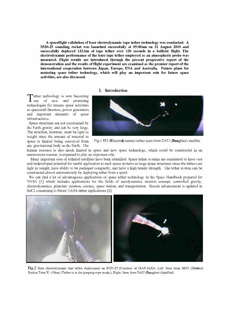
Space structures are not constrained by the Earth gravity and can be very large. The structure, however, must be light in weight since the amount of material in space is limited being conveyed from Fig. 1 ED (Electrodynamic) tether seen from DAU (Daughter) satellite any gravitational body as the Earth. The human resource is also much limited in space and new space technology, which could be constructed in an autonomous manner, is expected to play an important role.
Many important uses of tethered satellites have been identified. Space tether systems are considered to have vast and undeveloped potential for useful application to such space systems as large space structures since the tethers are light in weight, have ability to be packaged compactly, and have a high tensile strength. The tether system can be constructed almost autonomously by deploying tether from a spool. We can find a lot of advantageous applications of space tether technology in the Space Handbook prepared for
NASA [1] which includes applications for the fields of aerodynamics, mission concept, controlled gravity, electrodynamics, planetary mission, science, space station, and transportation. Recent advancement is updated in Ref.2 concerning to future NASA tether applications [2].
Fig .2 Bare electrodynamic tape tether deployment on S520-25 [Courtesy of ISAS/JAXA, Left: Seen from MOT (Mother)
Rocket Time X+158sec (Tether is in the jumping rope mode.), Right: Seen from DAU (Daughter) Satellite]
An electrodynamic tether is a long conductive cable or tape made from an electricity conductive material such as aluminum. Electrons subtracted from ionosphere enters at one end and issues at the other end for the electro-dynamic tether orbiting the Earth. The Earth's magnetic field then generates electric voltage in the electro-dynamic tether. The electro-dynamic tether can be employed as a generator to transfer orbital energy into electrical energy and also as a thruster to transfer electric energy into orbital energy [3],[4].
This paper describes a space experimental project concerning to the scientific and engineering verification of space tether technology. The project, T-Rex (Tether Rocket experiment), employed an S520 sounding rocket in a ballistic flight and extended the bare tape tether (Figs.l and 2). The sounding rocket was launched successfully on 31 August 2010 by ISAS/JAXA. The bare (i.e., uninsulated) electrodynamic tether was used in the experiment to measure its electrodynamic performance [5].
The space tether technology is indispensable in constructing and also maintaining large space structures, which are designed for future space development including the solar power satellite and deep space exploration. The proposal is to verify the fundamental technology for such important tether technology as deployment and use of bare conductive tether in space. The project towards space tether experiment is introduced in the paper and discussed in detail including the present status for the accomplishment. The paper will also include discussion of the further future plan to accomplish the space tether technology which will play an important role for our future space activity.
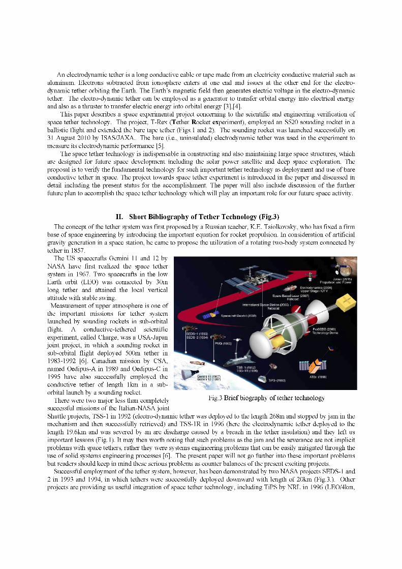
II. Short Bibliography of Tether Technology (Fig.3)
The concept of the tether system was first proposed by a Russian teacher, KE. Tsiolkovsky, who has fixed a firm base of space engineering by introducing the important equation for rocket propulsion. In consideration of artificial gravity generation in a space station, he came to propose the utilization of a rotating two-body system connected by tether in 1857.
The US spacecrafts Gemini 11 and 12 by NASA have first realized the space tether system in 1967. Two spacecrafts in the low Earth orbit (LEO) was connected by 30m long tether and attained the local vertical attitude with stable swing. Measurement of upper atmosphere is one of
the important missions for tether system launched by sounding rockets in sub-orbital flight. A conductive-tethered scientific experiment, called Charge, was a USA-Japan joint project, in which a sounding rocket in sub-orbital flight deployed 500m tether in 1983-1992 [6]. Canadian mission by CSA, named Oedipus-A in 1989 and Oedipus-C in 1995 have also successfully employed the conductive tether of length 1km in a suborbital launch by a sounding rocket.
There were two major less than completely FlS-3 Brief biography of tether technology successful missions of the Italian-NASA joint Shuttle projects, TSS-1 in 1992 (electro-dynamic tether was deployed to the length 268m and stopped by jam in the mechanism and then successfully retrieved) and TSS-1R in 1996 (here the electrodynamic tether deployed to the length 19.6km and was severed by an arc discharge caused by a breach in the tether insulation) and they left us important lessons (Fig. 1). It may then worth noting that such problems as the jam and the severance are not implicit problems with space tethers, rather they were systems engineering problems that can be easily mitigated through the use of solid systems engineering processes [6]. The present paper will not go further into these important problems but readers should keep in mind these serious problems as counter balances of the present exciting projects.
Successful employment of the tether system, however, has been demonstrated by two NASA projects SEDS-1 and 2 in 1993 and 1994, in which tethers were successfully deployed downward with length of 20km (Fig.3.). Other projects are providing us useful integration of space tether technology, including TiPS by NRL in 1996 (LEO/4km,
Long life tether, on-orbit), YES by ESA in 1997 (LEO /50km, Deorbit, not deployed), and ATEx by NRL in 1998 (LEO / 6km, Stability and control demonstrator, not deployed. Fig.3.). We are now faced to a new phase of space technology employed with space tether technology. Some of the
upcoming projects employed with tether technology include (not in any order) 1) Reboost of the International Space Station (ISS) by an electro-dynamic tether with length < 10km to elevate its
altitude without expense of any fuel (Fig.3); 2) The Aurora observer proposed by JAXA in high elliptical orbit (HEO) with perigee at 100km through
multipoint (5-point) atmospheric observation; 3) Bare tether experiments such as the Japan/Europe/USA joint project employing a sounding rocket in sub
orbital flight using a lkm-long bare electro-dynamic tether [5]. 4) A small satellite mission to verify the orbit elevation without expending any fuel mass and to study the Alfven-
wave phenomenon; 5) A sample collector at an asteroid in a "Hayabusa-like" mission. 6) Sun-tower solar power satellite proposed by NASA [7]; 7) Tethered Space Solar Power Satellite proposed by USEF, Japan [8]; 8) Rotating electro-dynamic tether application to enable simple entry into the atmosphere of the Jupiter [9, 10];
and 9) Space elevator proposed by NASA in geo-synchronous earth orbit (GEO) with tether of length 100,000km to
enable us electric transportation from the Earth to space (Not shown in Fig.3) [11, 12]. Tether experiment in space is not easy since the tether system could be quite big with large dimensions extending
to kilometers in length, and possibly interacting with other orbiting vehicles. The tether experiment in the suborbital flight using sounding rockets thus provides us useful demonstration of the space tether system although tether length extends to less than 1km. A new method to deploy bare electro-dynamic tape tether is discussed first since highly reliable deployment is the most important process of the tether technology. The tape-type tether has the advantages on survivability and electricity conductivity due to its wide surface area and thin thickness in comparison with the simple tether. A tether system may extend more than ten kilometers depending on its material strength with density. A tether
system can also be deployed simply by unwinding the tether from a spool autonomously, not requiring the presence of astronauts.
It should be noted here that the projects introduced in this paper are supported by the members of the international cooperation on the tether technology established from 1998 [13].
III. Bare Electrodynamic Tape Tether The tape tether is designed to be more survivable in the orbital debris environment than a normal string tether
since its projected area in the direction of the thickness decreases and the wide width direction assures resistance against the severance. The bare tape tether is proven to gather greater amount of electricity in comparison with the normal string tether in the ground plasma chamber experiment. The bare electro-dynamic tape tether is thus expected to have an excellent performance in many space experiments.
There have been numerous in space demonstrations involving tethers, even long tape tethers. T-Rex used a never-before-demonstrated method for the tape tether deployment by unfolding the tape in a manner analogous to that used by a fireman's hose. Some simple ground experiments and numerical simulations were conducted to understand and predict its performance. One particular technical challenge faced by T-Rex, as a sounding rocket experiment, was the requirement to deploy the tape tether in no more than 100 seconds - and to do so reliably.
IV. Verifications of Tether Technology in Space by Sounding rocket experiment
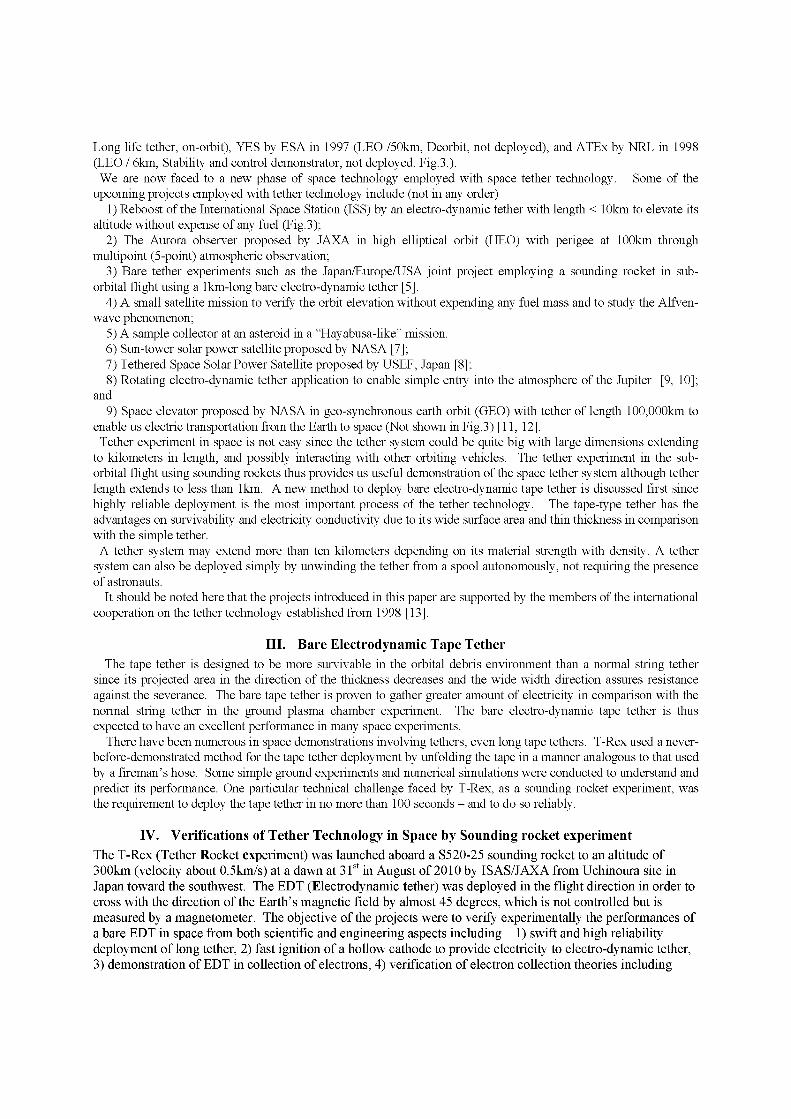
The T-Rex (Tether Rocket experiment) was launched aboard a S520-25 sounding rocket to an altitude of 300km (velocity about 0.5km/s) at a dawn at 31st in August of 2010 by ISAS/JAXA from Uchinoura site in Japan toward the southwest. The EDT (Electrodynamic tether) was deployed in the flight direction in order to cross with the direction of the Earth's magnetic field by almost 45 degrees, which is not controlled but is measured by a magnetometer. The objective of the projects were to verify experimentally the performances of a bare EDT in space from both scientific and engineering aspects including 1) swift and high reliability deployment of long tether, 2) fast ignition of a hollow cathode to provide electricity to electro-dynamic tether, 3) demonstration of EDT in collection of electrons, 4) verification of electron collection theories including
Altitude
301 BIT,
MAX:-3kV 10mA
| 400s | 500s |
Time
Fig.4 Experimental sequence of the sounding rocket experiment
OML (Orbit Motion Limited) theory, 5) demonstrate atmospheric entry of tape tether, and 6) test space robot motion control.
The tether was a bare EDT, which is a reinforced aluminum with width 25mm and thickness 0.05mm, and the science experiments employs the Langmuir tube as a main measurement device. The tether was deployed in its length in 120 seconds in order to afford sufficient time periods for science experiments of about 300 seconds in space. Experimental sequence of the sounding rocket experiment is shown in Fig.4.
T-Rex successfully completed most of its technical objectives and the technologies demonstrated will play important roles in the course of future space development. Specifically, a conductive tether opens unique opportunities for science that are not limited to testing OML collection under orbital conditions and generating convenient electron beams. The project is an European/ American/ Australian/ Japanese International Campaign and the team of the project consists of (at the start of the project) Hironori A. Fujii, Takeo Watanabe, Hironori Sahara, Tairo Kusagaya, Hirohisa Kojima and Koh-Ichiro Oyama at Tokyo Metropolitan University, Japan, Susumu Sasaki, Kohji Tanaka, Takumi Abe, and Manabu Shimoyama at ISAS/JAXA, Japan, Yoshiki Yamagiwa, and Hirotaka Ohtsu at Shizuoka University, Japan, and Mengu Cho at Kyusyu Institute of Technology, Japan, Tom Hada at Kyusyu University, Japan, Juan R. Sanmartin, and Mario Charro at Unversidad Politecnica de Madrid, Spain, Alain Hilgers and Jean-Pierre Lebreton at ESA, Europe, Michiel Kruijff, Erick J. van der Heide, and Fabio De Pascale at Dealta-Utec,SRC, Netherlands, John Williams and Binyamin Rubin at Colorado State
University, USA, Les Johnson at NASA/MSFC and George V. Khazanov at NASA/GSFC, USA, and Pavel M. Trivailo and Paul Williams at Royal Melbourne Institute of Technology, Australia.! !
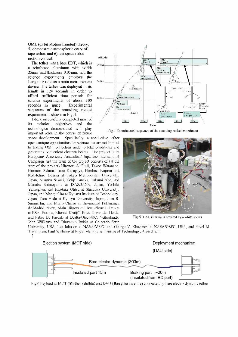
Fig. 5 DAU (Spring is covered by a white sheet)
Ejection system (MOT side) Deployment mechanism
(DAU side)
Bare electro-dynamic (300m)
Insulated part 15m Braking part ~20m (insulated from ED part)
Fig.6 Payload as MOT (Mother satellite) and DAU (Daughter satellite) connected by bare electro-dynamic tether
V. Space Demonstration (Engineering experiment) The sounding rocket, S520-25 was launched at 500(JST)
on 31 August 2010 from Uchinoura space observatory in elevation angle of 82.5 degree. The flight was normal and the nose cone off after 55 sec, the plasma prove (FLP, SPP) was deployed and started measurement in 58 sec. The DAU(Daughter satellite) was ejected from the MOT (Mother satellite) by three springs 120 seconds after the launch, i.e., (X+120). Three springs were set compressed and fixed by three hooks constrained by a wire, which is designed to sustaining the maximum load of 100G along the axis. At the ejection the wire was cut by a wire cutter (a pyrotechnic) on a signal from the rocket. The DAU was ejected by the speed about 3m/s and departed from the MOT deploying the tether as shown in Fig.6. Then the ED tether was deployed as scheduled in 120 sec and a movie showing the deployment was transmitted to the ground station through Ku telemeter. Figure2 shows the ED tether deployed by three ejection springs [Fig.5] and a view from the DAU (Daughter satellite) where the rocket is seen as a star behind connected tether.
The payload of the sounding rocket consists of MOT (Mother satellite) and DAU (Daughter satellite) connected by the bare electro-dynamic tether, tether deployment system, scientific measurement devices, hollow cathode unit, and a battery in the MOT. The root part of EDT is insulated for the length 15m in order to avoid electrical contact with the MOT.! The bare electro-dynamic tether is deployed in a new
"Inverse ORIGAMI" method [5].!
The rocket reached its maximum altitude of 309km in I 283seconds after the launch and ejected into south-east sea of Uchinoura.
A. Deployment of tape tether [14] The present mission requires a reliable and robust
deployer because the bare tape tether is shown to have many unknown dynamic characteristics and a complex dynamic behavior. The deployment system employs a foldaway storage method. The present foldaway tape tether deployer is based on a new concept "Inverse ORIGAMI" method [5] and is totally different from the usual reel type tether deployers. This innovative storage method can afford reliable fast deployment and is a key idea of the proposal to satisfy the requirements of the science mission.
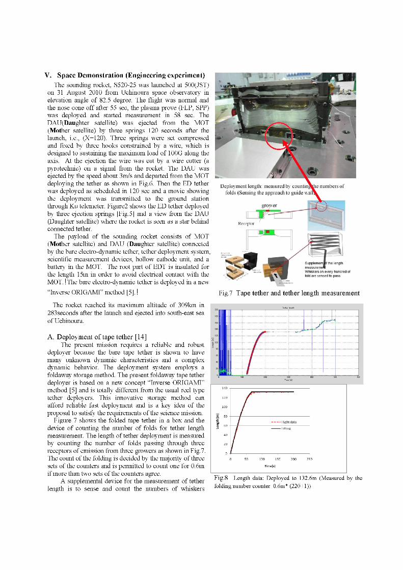
Figure 7 shows the folded tape tether in a box and the device of counting the number of folds for tether length measurement. The length of tether deployment is measured by counting the number of folds passing through three receptors of emission from three growers as shown in Fig.7. The count of the folding is decided by the majority of three sets of the counters and is permitted to count one for 0.6m if more than two sets of the counters agree.
A supplemental device for the measurement of tether length is to sense and count the numbers of whiskers
• U J ^ H
[he lerjgrti
wtii ikers on every hundred ef told are sensed to pass
Fig.7 Tape tether and tether length measurement
KQ z« n> wr no n
Fig.8 Length data: Deployed to 132.6m (Measured by the
folding number counter 0.6m* (220+1))
attached at every hundred of folds as shown in Fig.7 and also to sense different colors marked at every 25m.
In order to remove any effect due to contaminations, the initial velocity of the deployment is given by the kinetic energy of loaded springs installed on the ejector with long stroke-guide shafts. The deployment sequence is designed under the constraints of the system including tape tether toughness and structural load constraints. The initial velocity is given to the DAU in order to deploy the tape tether.
A brake system is designed to generate optimal force by the friction of brake pad so the DAU will be decelerated by the brake in order to stop gradually and not to bounce back at the end of the deployment.
In order to confirm the high-reliability of the spring ejection mechanism and stability of tether in the deployment, eleven schemes of demonstration are employed in the preliminary phase of the present project including, 1) on a flat air table, 2) on a tower system, 3) in a vacuum chamber, 4) by pet-bottle model rocket, 5) on a linear-motor car, 6) by a cart model, 7) on a spinning flight table, 8) on micro-gravity by a parabolic flight, 9) vertical ejection test, 10) horizontal extraction test, and 11) numerical simulation. All experimental results have demonstrated the high-reliability performance of the present deployment system in every different simulation environment. The space demonstration completes the twelfth confirmation to suffice one dozen schemes.
Figure 8 shows the result of tether deployment in the present space demonstration and its fitting curve. The folding number is counted for (220+1) times and it is shown that the tape tether was deployed to 132.6m (0.6m per count: error exists as less counting for a few of fold.). The data is also confirmed by the data obtained by the string sensors and the color sensor by every checker point at 25, 50, 75, 100, and 125m.! !
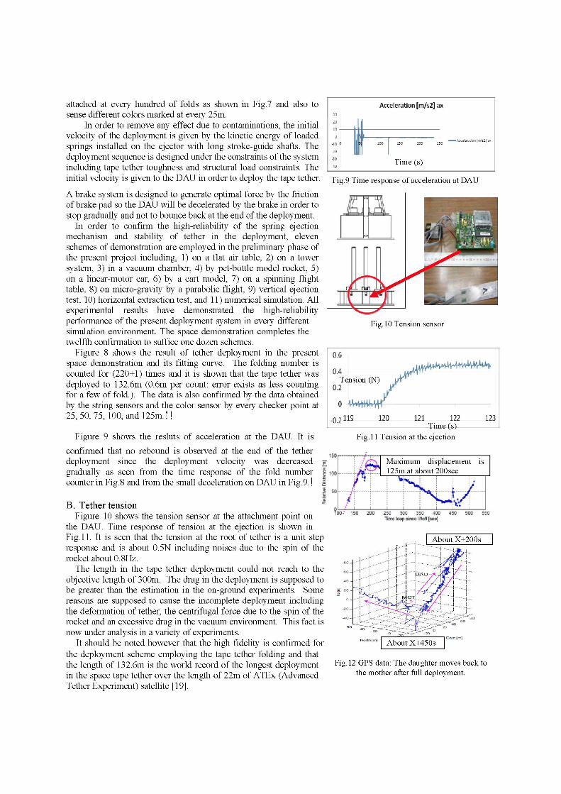
Figure 9 shows the resluts of acceleration at the DAU. It is
confirmed that no rebound is observed at the end of the tether deployment since the deployment velocity was decreased -g gradually as seen from the time response of the fold number counter in Fig. 8 and from the small deceleration on DAU in Fig. 9.! s
'. V
B. Tether tension Figure 10 shows the tension sensor at the attachment point on
the DAU. Time response of tension at the ejection is shown in Fig. 11. It is seen that the tension at the root of tether is a unit step response and is about 0.5N including noises due to the spin of the rocket about 0.8Hz.
The length in the tape tether deployment could not reach to the objective length of 300m. The drag in the deployment is supposed to be greater than the estimation in the on-ground experiments. Some reasons are supposed to cause the incomplete deployment including the deformation of tether, the centrifugal force due to the spin of the rocket and an excessive drag in the vacuum environment. This fact is now under analysis in a variety of experiments.
It should be noted however that the high fidelity is confirmed for the deployment scheme employing the tape tether folding and that the length of 132.6m is the world record of the longest deployment in the space tape tether over the length of 22m of ATEx (Advanced Tether Experiment) satellite [19].
Acceleration [m/s2] nx
•
-ALCSwaciiki I ruto I a*
Time (s)
Fig.9 Time response of acceleration at DAU
& • •A
Fig. 10 Tension sensor
Fig. 11 Tension at the ejection
I / / f v Maximum displacement is
125m at about 200sec 1—5S
_! 1 I I I I I l_ TOO-' 150 200 250 300 350 400 450 600 5S0
Time leap since liftoff [sec]
Fig. 12 GPS data: The daughter moves back to the mother after full deployment.
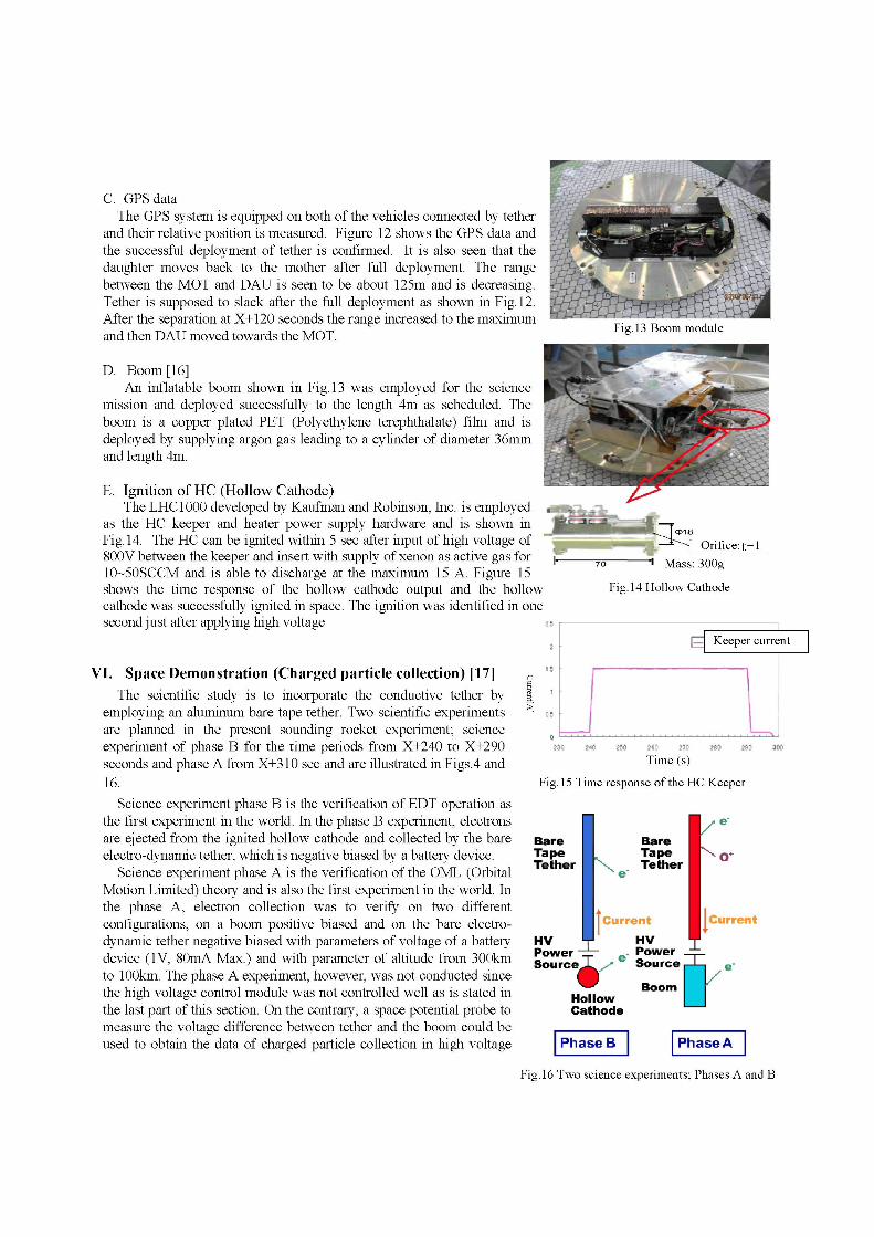
C. GPS data The GPS system is equipped on both of the vehicles connected by tether
and their relative position is measured. Figure 12 shows the GPS data and the successful deployment of tether is confirmed. It is also seen that the daughter moves back to the mother after full deployment. The range between the MOT and DAU is seen to be about 125m and is decreasing. Tether is supposed to slack after the full deployment as shown in Fig. 12. After the separation at X+120 seconds the range increased to the maximum and then DAU moved towards the MOT.
D. Boom [16] An inflatable boom shown in Fig. 13 was employed for the science
mission and deployed successfully to the length 4m as scheduled. The boom is a copper plated PET (Polyethylene terephthalate) film and is deployed by supplying argon gas leading to a cylinder of diameter 36mm and length 4m.
E. Ignition of HC (Hollow Cathode) The LHC1000 developed by Kaufman and Robinson, Inc. is employed
as the HC keeper and heater power supply hardware and is shown in Fig. 14. The HC can be ignited within 5 sec after input of high voltage of 800V between the keeper and insert with supply of xenon as active gas for 10-50SCCM and is able to discharge at the maximum 15 A. Figure 15 shows the time response of the hollow cathode output and the hollow cathode was successfully ignited in space. The ignition was identified in one second just after applying high voltage
VI. Space Demonstration (Charged particle collection) [17] The scientific study is to incorporate the conductive tether by
employing an aluminum bare tape tether. Two scientific experiments are planned in the present sounding rocket experiment; science experiment of phase B for the time periods from X+240 to X+290 seconds and phase A from X+310 sec and are illustrated in Figs.4 and 16.
Science experiment phase B is the verification of EDT operation as the first experiment in the world. In the phase B experiment, electrons are ejected from the ignited hollow cathode and collected by the bare electro-dynamic tether, which is negative biased by a battery device.
Science experiment phase A is the verification of the OML (Orbital Motion Limited) theory and is also the first experiment in the world. In the phase A, electron collection was to verify on two different configurations, on a boom positive biased and on the bare electro-dynamic tether negative biased with parameters of voltage of a battery device (IV, 80mA Max.) and with parameter of altitude from 300km to 100km. The phase A experiment, however, was not conducted since the high voltage control module was not controlled well as is stated in the last part of this section. On the contrary, a space potential probe to measure the voltage difference between tether and the boom could be used to obtain the data of charged particle collection in high voltage
Mass: 300g
Fig. 14 Hollow Cathode
i Z Keeper current
.. L 230 2-K 250 2t0 2T0 280 290 3€0
Time (s)
Fig. 15 Time response of the HC Keeper
Bare Tape Tether
HV Power" Source
Bare Tape Tether
Current Current
HV Power _ ^
" Source,—U
Hollow Cathode
Boom r Phase B PhaseA
Fig. 16 Two science experiments; Phases A and B
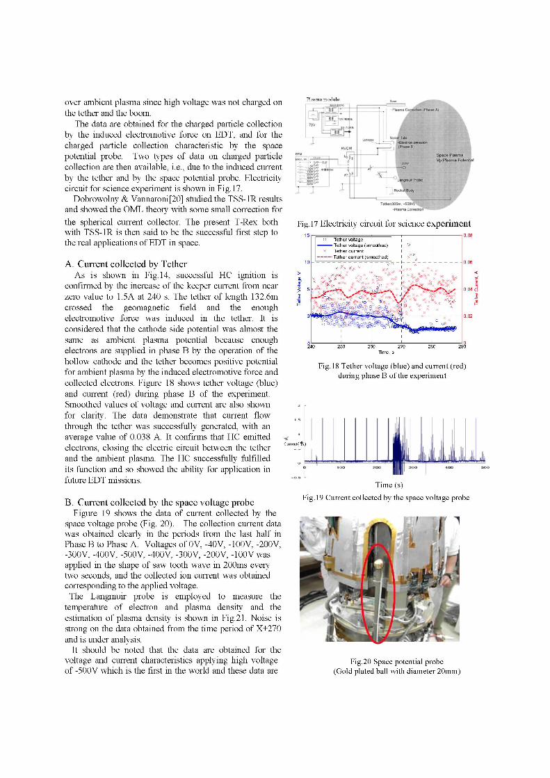
over ambient plasma since high voltage was not charged on the tether and the boom.
The data are obtained for the charged particle collection by the induced electromotive force on EDT, and for the charged particle collection characteristic by the space potential probe. Two types of data on charged particle collection are then available, i.e., due to the induced current by the tether and by the space potential probe. Electricity circuit for science experiment is shown in Fig. 17.
Dobrowolny & Vannaroni[20] studied the TSS-1R results and showed the OML theory with some small correction for the spherical current collector. The present T-Rex both with TSS-1R is then said to be the successful first step to the real applications of EDT in space.
A. Current collected by Tether As is shown in Fig. 14, successful HC ignition is
confirmed by the increase of the keeper current from near zero value to 1.5A at 240 s. The tether of length 132.6m crossed the geomagnetic field and the enough electromotive force was induced in the tether. It is considered that the cathode side potential was almost the same as ambient plasma potential because enough electrons are supplied in phase B by the operation of the hollow cathode and the tether becomes positive potential for ambient plasma by the induced electromotive force and collected electrons. Figure 18 shows tether voltage (blue) and current (red) during phase B of the experiment. Smoothed values of voltage and current are also shown for clarity. The data demonstrate that current flow through the tether was successfully generated, with an average value of 0.038 A. It confirms that HC emitted electrons, closing the electric circuit between the tether and the ambient plasma. The HC successfully fulfilled its function and so showed the ability for application in future EDT missions.
B. Current collected by the space voltage probe Figure 19 shows the data of current collected by the
space voltage probe (Fig. 20). The collection current data was obtained clearly in the periods from the last half in Phase B to Phase A. Voltages of 0 V, -40V, -100V, -200V, -300V, -400V, -500V, -400V, -300V, -200V, -lOOVwas applied in the shape of saw tooth wave in 200ms every two seconds, and the collected ion current was obtained corresponding to the applied voltage.
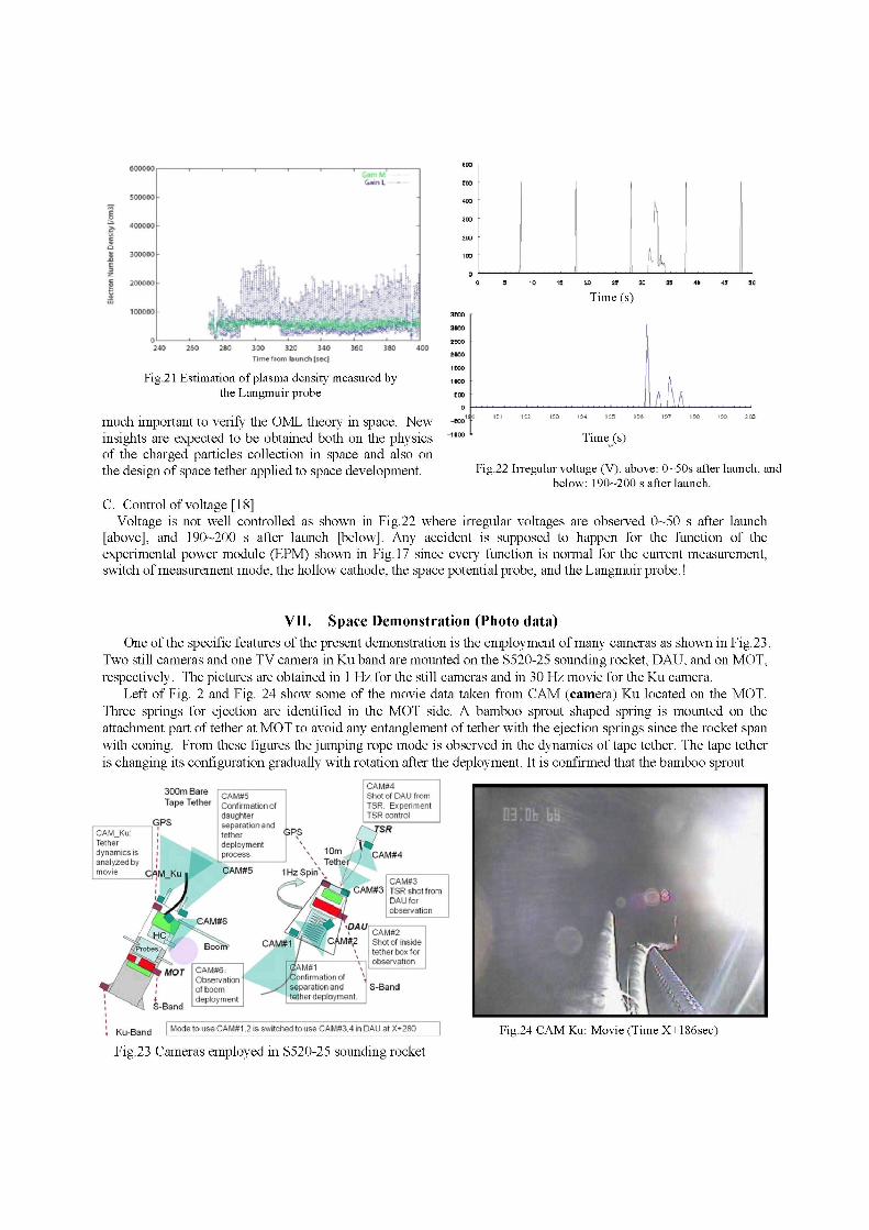
The Langmuir probe is employed to measure the temperature of electron and plasma density and the estimation of plasma density is shown in Fig.21. Noise is strong on the data obtained from the time period of X+270 and is under analysis.
It should be noted that the data are obtained for the voltage and current characteristics applying high voltage of -500V which is the first in the world and these data are
Plasma module
• Plwflvi corteWf
Fig. 17 Electricity circuit for science experiment
o Tether wltage ^ ^ — Tether wltage (smoothed)
x Tether current Tether current (smoothed)
6&e»e i0-04 d
260 270 Time, s
Fig. 18 Tether voltage (blue) and current (red) during phase B of the experiment
Cuirent( %)
jJLili,,L — i Lk Time (s)
Fig. 19 Current collected by the space voltage probe
Fig.20 Space potential probe (Gold plated ball with diameter 20mm)
E
Time (s)
300 320 340
Tin** tiom launch [ K t ]
Fig.21 Estimation of plasma density measured by the Langmuir probe
much important to verify the OML theory in space. New insights are expected to be obtained both on the physics of the charged particles collection in space and also on the design of space tether applied to space development.
up™
a BOO
2 S »
SKM
i r e o
1KW
E00
- S J C
-1J00
o i t i i * i if.^ 134 1 H
Time (s)
1 • • • ;
l\ Uh,
197 tS3 : • • • •
Fig.22 Irregular voltage (V), above: 0~50s after launch, and below: 190-200 s after launch.
C. Control of voltage [18] Voltage is not well controlled as shown in Fig.22 where irregular voltages are observed 0~50 s after launch
[above], and 190-200 s after launch [below]. Any accident is supposed to happen for the function of the experimental power module (EPM) shown in Fig. 17 since every function is normal for the current measurement, switch of measurement mode, the hollow cathode, the space potential probe, and the Langmuir probe.!
VII. Space Demonstration (Photo data) One of the specific features of the present demonstration is the employment of many cameras as shown in Fig.23.
Two still cameras and one TV camera in Ku band are mounted on the S520-25 sounding rocket, DAU, and on MOT, respectively. The pictures are obtained in 1 Hz for the still cameras and in 30 Hz movie for the Ku camera.
Left of Fig. 2 and Fig. 24 show some of the movie data taken from CAM (camera) Ku located on the MOT. Three springs for ejection are identified in the MOT side. A bamboo sprout shaped spring is mounted on the attachment part of tether at MOT to avoid any entanglement of tether with the ejection springs since the rocket span with coning. From these figures the jumping rope mode is observed in the dynamics of tape tether. The tape tether is changing its configuration gradually with rotation after the deployment. It is confirmed that the bamboo sprout
300m Bare Tape Tether
GPS CAM_Ku: Tether dynamics is analyzed by movie CAM Ku
CAMS5 Confirmation ot daughter separation and tether deployment process
. CAMS4 I Shot of DAU from : TSR. Experiment i TSR control
GPS
CAM#5
or CAM#4
Tether •' 1 H l S p i n \ :/
10m
CAM#3 CAM#3 TSR shot from
DAU for observation
CAM#6: Observation
, of boom I deployment
M#1 ifirmation of
separation and tether deployment
i Ku -Band Mode to use CAMS1.2 is switched to use CAMS3.4 in DAU at X+280 Fig.24 CAM Ku: Movie (Time X+186sec)
Fig.23 Cameras employed in S520-25 sounding rocket
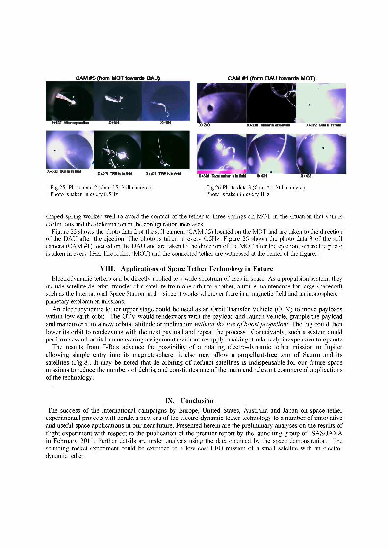
Fig.25 Photo data 2 (Cam #5: Still camera); Fig.26 Photo data 3 (Cam #1: Still camera), Photo is taken in every 0.5Hz Photo is taken in every 1Hz
shaped spring worked well to avoid the contact of the tether to three springs on MOT in the situation that spin is continuous and the deformation in the configuration increases.
Figure 25 shows the photo data 2 of the still camera (CAM #5) located on the MOT and are taken to the direction of the DAU after the ejection. The photo is taken in every 0.5Hz. Figure 26 shows the photo data 3 of the still camera (CAM #1) located on the DAU and are taken to the direction of the MOT after the ejection, where the photo is taken in every 1Hz. The rocket (MOT) and the connected tether are witnessed at the center of the figure.!
VIII. Applications of Space Tether Technology in Future Electrodynamic tethers can be directly applied to a wide spectrum of uses in space. As a propulsion system, they
include satellite de-orbit, transfer of a satellite from one orbit to another, altitude maintenance for large spacecraft such as the International Space Station, and - since it works wherever there is a magnetic field and an inonosphere -planetary exploration missions.
An electrodynamic tether upper stage could be used as an Orbit Transfer Vehicle (OTV) to move payloads within low earth orbit. The OTV would rendezvous with the payload and launch vehicle, grapple the payload and maneuver it to a new orbital altitude or inclination without the use of boost propellant. The tug could then lower its orbit to rendezvous with the next payload and repeat the process. Conceivably, such a system could perform several orbital maneuvering assignments without resupply, making it relatively inexpensive to operate.
The results from T-Rex advance the possibility of a rotating electro-dynamic tether mission to Jupiter allowing simple entry into its magneto sphere, it also may allow a propellant-free tour of Saturn and its satellites (Fig. 8). It may be noted that de-orbiting of defunct satellites is indispensable for our future space missions to reduce the numbers of debris, and constitutes one of the main and relevant commercial applications of the technology.
IX. Conclusion
The success of the international campaigns by Europe, United States, Australia and Japan on space tether experimental projects will herald a new era of the electro-dynamic tether technology to a number of innovative and useful space applications in our near future. Presented herein are the preliminary analyses on the results of flight experiment with respect to the publication of the premier report by the launching group of ISAS/JAXA in February 2011. Further details are under analysis using the data obtained by the space demonstration. The sounding rocket experiment could be extended to a low cost LEO mission of a small satellite with an electrodynamic tether.
Acknowledgments The authors thank ISAS/JAXA for supporting the project, also the launching members of S520-25.
References Cosmo, M.L., and Lorenzini, Tethers In Space Handbook, NASA Marshall Space Flight Center, December 1977.
Johnson,L., Gilchrist,B., Estes,R.D., and Lorenzini,E., "Overview of Future NASA Tether Applications," Advances in Space
Research, Vol.24, No.4, 1999, pp.1055-1063.
Lorenzini,E., and Sanmartin,J., "Electrodynamic Tethers in Space," Scientific American, August 2004, pp.50-57.
Person, Joseph Carrol et al, "Overview of the Electrodynamic Delivery Express," AIAA 2003-4790, 2003.
H. A. Fujii, T. Watanabe, H. Kojima, K-I. Oyama, T. Kusagaya, Y. Yamagiwa, H. Ohtsu, M. Cho, S. Sasaki, K. Tanaka,
J.Williams, B. Rubin, C. L. Johnson, G. Khazanov, J. R. Sanmartin, J-P. Lebreton, E. J. van der Heide, M. Kruijff, F. De Pascale,
P. M. Trivailo, "Sounding rocket experiment of bare electrodynamic tether system," Acta Astronautica, Journal of the
International Academy of Astronautics, Vol.64, No.2-3, January/February 2009, 313-324. 6 S.Sasaki, K.I. Oyama, N. Kawashima, T. Obayashi, K.Hirano, W.J. Raitt, N.B. Myers, P.M. Williamson, P.M. Banks, and W. F.
Sharp,. "Tethered Rocket Experiment (CHARGE-2): Initial Results on electrodynamics," Radio Science, Vol.23, No.975, 1988.
Feingold,H., Stancati,M., Friedlander,A., Jacobs,M., and Mankins,J.C, "Space Solar Power - A Fresh Look at the feasibility of
Generating Solar Power in Space for Use on Earth," NASA Report No. SAIC-97/1005, 4 April 1997.
Report on Technology Assessment for Utilization of Space Solar Power Satellite, Institute for unmanned Space Experiment Free
Flyer, Japan, March 2003.(in Japanese)
Sanmartin, J.R., and Lorenzini, E.C., "Exploration of Outer Planets Using Tethers for Power and Propulsion," Journal of
Propulsion and Power, Vol.21, No.3, May-June 2005, pp.573-576.
Sanmartin, J.R., and Lorenzini, E.C., "Exploration of the Jovian System Trapping Jupiter's Rotational Energy," Special
Lecture at Tokyo MIT, 11 April 2005.
Space Science home page, (http://spacescience.com/headlines/y2000/ast07sep_l.htm71ist).
LiftPort- The Space Elevator Company- LiftPort Group (http://www.liftport.com/)
H.A. Fujii, and K. Yasumitsu, ed, "Proceedings of the meeting on International Tether System," 12-14 January 1998, Tokyo
Metropolitan Institute of Technology, Tokyo, JAPAN.
T.Watanabe, et.al., "Deployment of bare electro-dynamic tape tether on sounding rocket S520-25 (in Japanese)," submitted to
the Japan society for Aeronautical and Space Science, Space Technology.
M. Nohmi, et.al., "Experiment of attitude control of a tethered space robot on sounding rocket (in Japanese)", submitted to the
Japan society for Aeronautical and Space Science, Space Technology.
H.Sahara,et.al," Development of an inflatable extending boom and its verification by a sounding rocket experiment (in
Japanese)", submitted to the Japan society for Aeronautical and Space Science, Space Technology.
Y. Yamagiwa, et.al., " Verification Experiment of Bare Electrodynamic Tether operation and charged particle collection theory
by using sounding rocket (in Japanese)," submitted to the Japan society for Aeronautical and Space Science, Space Technology.
ISAS/JAXA "Progress report of the sounding rocket 520-25"(in Japanese),to appear July 2011.
http://code8100.nrl.navy.mil/programs/atex.htm
G. Vannaroni, M. Dobrowolny, F. De Venuto, L. less, Current Collection by Rapidly Moving Charged Bodies in the
Ionosphere: TSS-1R Results, 6th Spacecraft Charging Technology Conference, AFRL-VS-TR-20001578, 1 September 2000


![Tether anthony[1]](https://img.dokumen.tips/doc/110x75/557c7d36d8b42a494c8b5161/tether-anthony1.jpg)