Embed Size (px)
Citation preview

IMPROVESTANDARD OPERATING PROCEDURES
SOP 226Annual Site Maintenance
Date Last Modified Modified by:09/12/96 EAR

SOP 226: Annual Site Maintenance 2
SOP 226 Annual Site Maintenance
TABLE OF CONTENTS1.0 PURPOSE AND APPLICABILITY.......................................................................... 32.0 RESPONSIBILITIES................................................................................................ 3
2.1 Field Specialist....................................................................................................... 32.2 Site Operator ......................................................................................................... 32.3 Field Technician..................................................................................................... 3
3.0 REQUIRED EQUIPMENT AND MATERIALS....................................................... 44.0 METHODS............................................................................................................... 6
4.1 Preparation for Annual Maintenance Loop ............................................................ 64.2 Annual Site Maintenance ...................................................................................... 8
4.2.1 Pre-Maintenance Inspection at Site ................................................................. 84.2.2 Flow Rate Audit.............................................................................................. 94.2.3 Sampler Cleaning and Maintenance .............................................................. 13
4.2.3.1 Clean Cyclones, Cover Plates, and Stack Tee’s...................................... 134.2.3.2 Clean the Stacks, Inlets, Tees, and Stack Bottom Plugs. ........................ 144.2.3.3 Clean the Interior of the Modules and Check All Hoses, Wires, and
Connectors. .......................................................................................... 154.2.3.4 Check the Solenoids, Elapsed Timers, Vacuum Gauge, and Magnehelic. 154.2.3.5 Pump Maintenance................................................................................ 164.2.3.6 Inspect the Sampler Stand or Structure and the Sampling Modules........ 194.2.3.7 Inspect and Clean the Pump House or Pump Area. ................................ 204.2.3.8 Inspect the Controller Module. .............................................................. 214.2.3.9 Reinstall the Cyclone Assemblies in the Sampling Modules. ................... 224.2.3.10 Leak Check the Sampling Modules...................................................... 224.2.3.11 D Module Flow Inspection. ................................................................. 23
4.2.4 Sampler Calibration....................................................................................... 244.2.5 Post Calibration Check.................................................................................. 24
4.3 Operator Training and Review ............................................................................. 24
LIST OF FIGURESFigure 1 Site Maintenance Report................................................................................. 10Figure 2 Site Configuration Check List ......................................................................... 11Figure 3 Controller Module and Orifice Meter Configurations ....................................... 12
Technical ReferencesTI 176A Calibration of Audit Devices Using the SpirometerTI 176B Final Flow Rate Audit CalculationsTI 176C Flow Rate Audits and Adjustment ProceduresTI 176D IMPROVE Aerosol Sampler Operation Manual

SOP 226: Annual Site Maintenance 3
1.0 PURPOSE AND APPLICABILITY
This standard operating procedure (SOP) describes the procedures for annualmaintenance of equipment in the IMPROVE sampling network. Annual maintenance issolely the responsibility of the field specialist, or field technicians working for the AirQuality Group.
Prior to annual maintenance, the field technician shall review and summarize all theinformation collected at each site during the previous year in order to characterize thefunctioning of each site. The data recorded during weekly maintenance of the IMPROVEsamplers, as well as any problems detected during quality assurance procedures shall beincorporated into the site summary. This reference will be used to determine whetherextra maintenance or troubleshooting is required at each site.
Annual site maintenance shall be performed by Air Quality Group field technicians.Each site will be visited, the cyclones, stacks and inlets cleaned, the electronics checked,the pumps re-built or replaced, and the samplers audited and new calibration equationsrecorded. Operator training and review sessions, and sampler upgrades shall also beperformed at this time.
2.0 RESPONSIBILITIES
2.1 Field SpecialistThe field specialist shall:
• oversee and maintain records on site and sampler operation• schedule standard annual maintenance• review flow rate audits and calibration equations
2.2 Site OperatorThe site operator shall:
• note deviations from normal operation and inform Air Quality Group personnel• attend site operator training and review sessions during annual maintenance
2.3 Field TechnicianThe field technician shall:
• Perform annual site maintenance• Perform site operator training and review sessions• Maintain records on equipment repair and modification

SOP 226: Annual Site Maintenance 4
3.0 REQUIRED EQUIPMENT AND MATERIALSThe equipment and materials required to perform annual site maintenance and flow
rate audits are listed below.• Personal supplies: bug spray, sun screen, first aid supplies, dust mask, protective
goggles, gloves, water, flashlight, baby wipes.
• Cleaning supplies: Alcohol, Kimwipes , cotton tipped applicators, rags, test tubebrush for PM10 inlets, hand broom or paint brush for pump house and modules, stackcleaning brush (3” diameter nylon bristle bottle brush with a 9’ section of weighted lineattached), Scotch-brite pads for preparation for painting, silicone lubricant, graphitelubricant
• Audit and calibration supplies: 2 audit devices (calibrated magnehelics with orifice
meter probes), vacuum grease, Teflon tape, calculator, calibration cassettes, variableflow restriction device, felt tipped pens; red, blue, green and black, for markingnominal readings, calibration and audit sheets, #8 rubber stopper for leak checking thesampler, forceps
• Stand and external module repairs: lag bolts 1/4x20; 3", 5", nuts, bolts, and
washers1/4x20; 3", 5", 9", wood screws; 3", 5", nails, saw, sand paper, paint formodules, silicone sealant w/dispenser, masking tape (use when painting), PM10 stackgaskets, PM2.5 stack gaskets, vent covers
• Pump maintenance supplies: mufflers or brass nipples, orange gaskets, flapper valves,
cylinder gasket, aluminum spacer rings, cylinders, brown Teflon piston rings, pistonscrews, pump capacitors, NPT to vacuum line brass fittings, spare vacuum tubing,vacuum line fittings, large relays for pump house, lock tight, pump house fan (large),delay timers
• Controller module: spare clock controller, fuses (a spare should be taped inside the
module), lock-out device, controller fan (small and narrow), override timer, relays(small, plug into base), relay hold down clips, transformers
• Sampling modules: spare cassette hoses, small self-tapping screws for faceplates,
elapsed timers, toggle switches, breaker switch, panduit connectors, spare wire; red,orange, yellow, green, blue, black, white, and purple, spare 6 wire cable, solenoids,solenoid o-rings: 2-011, spare tubing: cassette to solenoid, spare magnehelic, sparepressure gauge, valves w/set pins, wire ties, wire tie downs, colored tape, white stickerlabels
• Brass fittings and accessory parts: 5/8” vacuum line compression nuts, spare
magnehelic nipples, ¼ NPT to vacuum line brass elbows, CAJON VCO femaleconnector, CAJON VCO male connector, ¼ NPT pipe extender fitting.

SOP 226: Annual Site Maintenance 5
• Cyclone parts:cyclone port coverso-rings
o-rings old style new stylelower funnel to catch cup 2-118 samecyclone/T junction to lower funnel 2-130 2-128cyclone/T junction 2-123 samecyclone/T junction to upper funnel 2-124 samecyclone throat insert 2-014 sameupper funnel screw o-rings 2-008 nonemagnehelic port nipples 2-008 samecover plate to upper funnel 2-156 samecover plate inserts: upper o-ring 2-016 samecover plate inserts: lower o-ring 2-017 2-016cyclone T to stack bottom plug 2-216 samecyclone T to stack 2-222
solenoid o-ring 2-011 samedenuder screw o-ring 2-008 same
PM10 funnel o-rings 2-124 samePM10 inlet o-rings: Sierra 2-023 samePM10 inlet o-rings: Wedding 2-023 samePM2.5 inlet o-rings 2-129 same
magnehelic port nipples, magnehelic tubing, knurled knob on a 10-24x3" screw forcyclone cover plate, hold down clamps for filters, new cyclone T junctions with 10-24x1"screws, new cyclone cover plate inserts for old cover plates, right angle drill adapter,template for installing new T's for cyclones
• Inlet and stack parts: spare PM2.5 inlets, PM10 Wedding inlet cover plate screws,PM10 Sierra inlet water collection cups, stack bracket/holder, stack bottom plugs,stack bottom plug plugs, denuders, sheet metal screws for holding in denuders
• Tubing: spare vacuum tubing to replace any damaged or stressed tubing, Tygontubing (3/16” I.D., 1/16” wall) to replace weakened or damaged magnehelic hoses.
• Tool kit with 8" and 10" adjustable crescent wrench, channel lock pliers, needle nosepliers, cutting pliers, standard 1/4" through 11/16" combination wrench set, ignitionwrench set (including an 11/64” wrench), Phillips and Standard screwdrivers, wiresnips, wire crimping and stripping tool, utility knife, line powered drill, standard drillbit set, multimeter (AC/DC volt/ohm meter), wire ties, electrical tape, colored paperor vinyl tape (red, yellow, green, blue, black and white), and Teflon plumbers tape.

SOP 226: Annual Site Maintenance 6
4.0 METHODSAnnual maintenance is performed by field technicians, generally in the spring or summer.This annual visit to the site is an opportunity to repair non-vital sampler components,verify calibration equations, replace or update obsolete equipment, thoroughly clean eachsampling module, and test the vacuum systems. It also allows trained personnel to inspectthe site to ensure compliance with EPA sampling regulations, and provides an excellentopportunity for operator training.
The following sections describe the annual maintenance procedures.4.1 Preparation for annual maintenance loop4.2 Annual site maintenance4.3 Operator training and review
4.1 Preparation for Annual Maintenance LoopPreparation for annual site maintenance involves contacting each site, scheduling visit
dates and times, and creating a site audit and maintenance kit. The Field Specialist isresponsible for scheduling maintenance trips and overseeing the training and supplying ofthe field technicians both prior to leaving the Air Quality Group and while in the field.The process to prepare for annual maintenance loops is described in the following section.1. The Field Specialist notifies the appropriate land management departments of the
scheduled site visit at least one month prior to the visit date. The informationtransmitted includes which site or sites will be visited, the approximate date of thevisit(s), and the name of the visiting field technician.
2. The field technician assembles a maintenance loop notebook containing the followinginformation for each site:
• Flow histories for all modules• Results of the A vs. B module plot (PIXE Sulfur vs. SO4
-2 from IonChromatography) to determine whether there are discrepancies between themodules in air volume sampled.
• Photocopy of the audit form from which the current site calibration equationswere derived.
• Photocopy of the site maintenance report and comments from the previousyear
• Blank audit and calibration forms• Blank maintenance report and site configuration checklist forms from
V:\Field\Maint• Pump strength history• Notes and comments from the past year’s log sheets regarding sampler
problems.3. The field technician notifies the site operator of the impending visit at least two weeks
prior to scheduled date. The site operator should have received notification from theappropriate land management department of the scheduled visit prior to this time. Thefollowing topics are covered during operator notification.
• The exact date of scheduled maintenance at the site• Scheduling of operator training sessions
SOP 226: Annual Site Maintenance 7
• Details of site access, including keys, combinations, road conditions, etc.• Past performance of the sampler• Current problems the with the sampler, power, site, etc.
4. The field technician constructs, loads, and leak checks two cassettes for each filtersampling configuration. These cassettes, called annual maintenance audit cassettes,shall be used to set the nominal flow rate and perform audits in each module. The flowrates through both cassettes must agree, and must be consistent with the observedflow rates through the normal sampling cassettes installed at the site. IMPROVEnetwork cassette configurations include:• Module A cassette loaded with a Teflo filter and mask size M1 (area 2.2 cm2).• Module A cassette loaded with a Teflo filter and no mask.• Module A/S cassette loaded with a Teflo filter and mask size M1 (area 2.2 cm2)
in stage 1, and a Na2CO3 impregnated quartz filter in stage 2.• Module B cassette loaded with a Nylasorb filter.• Module C cassette loaded with a Pallflex quartz filter.• Module C/C cassette loaded with one Pallflex quartz filter in stage 1 and one in
stage 2.• Module D cassette loaded with a Teflo filter and no mask.• Module D/S cassette loaded with a Teflo filter and no mask in stage 1, and a
Na2CO3 impregnated quartz filter in stage 2.5. The field technician checks the calibration of two audit devices (orifice meters) with
the spirometer following the procedures of TI 176A. If the flow rates are not within2% of the previous calibration, the audit device is re-calibrated.
6. The field technician creates annual site flow rate audit sheets for each site being visitedusing the Autocal database, or manually as described in TI 176B.
7. The field technician assembles a tool kit and organizes a comprehensive parts kit.Parts and tools required for basic electrical and carpentry tasks should be included. Atthis time, the maintenance loop notebook should be reviewed to determine any extrawork or suspected problems for which the technician must be prepared.
8. The field technician prepares clean, coated denuders to replace the used denuders inthe B modules at each site. To clean and coat each denuder, the technician shall:a. Place the denuder in a 1 liter graduated cylinder in an ultrasound bath. Fill the
cylinder with 1 liter of de-ionized water, 10ml of reagent grade ammonia and 1/16teaspoon of Alconox glass cleaner.
b. Run the ultrasound bath for at least 30 minutes.c. Remove the denuder promptly and rinse thoroughly with hot water for several
minutes.d. Rinse the denuder with distilled de-ionized water.e. Allow the denuder to dry, rinsing it with reagent grade alcohol to remove all
water.f. Immerse the denuder completely in the Na2CO3 solution for several minutes,
agitating it to ensure all surfaces are coated• Stock solution should be in a labeled, sealed bottle on the supplies shelf in the
shop.

SOP 226: Annual Site Maintenance 8
• If none is available, create a solution of Na2CO3 and reagent grade glycerol indistilled water. The required concentrations are 71grams of Na2CO3 and 30mlof glycerol per liter of water. Agitate the solution thoroughly until all theNa2CO3 is dissolved. Heating the distilled water aids dissolving the Na2CO3.Store the Na2CO3 solution in a clean, sealed, labeled beaker.
g. Remove the denuder from the solution and allow it to air dry. Place it on clean labtowels over plastic to absorb excess Na2CO3 and protect the lab floor.
h. Store the denuder in a clean plastic bag labeled “Cleaned and Coated Denuders”.
4.2 Annual Site MaintenanceOnce the field technician has arrived at the site, the following procedures are
performed. 4.2.1 Pre-maintenance Inspection at the Site 4.2.2 Flow Rate Audit 4.2.3 Sampler Cleaning and Maintenance 4.2.4 Sampler Calibration
4.2.5 Post-calibration check
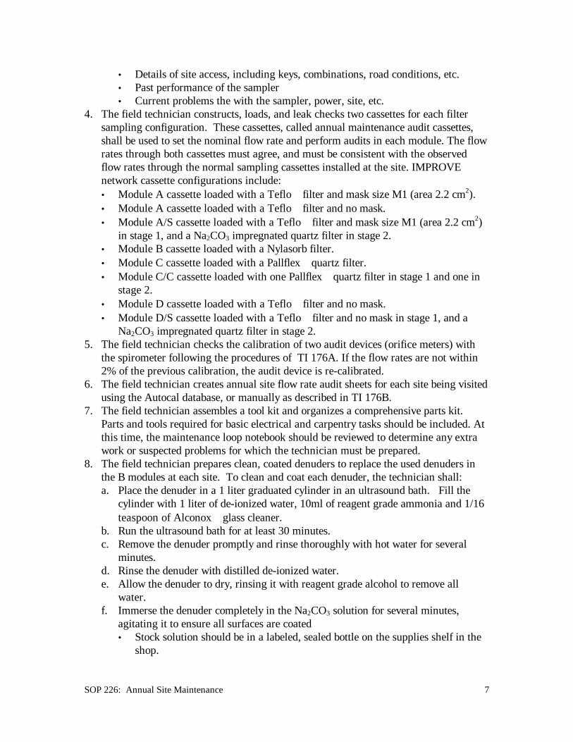
4.2.1 Pre-Maintenance Inspection at SiteThe pre-maintenance inspection involves filling out Figure 1 and Figure 2, forms
for describing the status of the site. Any repairs or changes to the sampler or siteshould be noted on these forms. These tables shall be filed with the annualmaintenance reports for each site as a record of actions taken at the site. Thefollowing is a review of the suggested pre-maintenance procedures.1. Determine the location of the breaker for power to the sampler2. Check the integrity of the sampler stand, noting any parts that require repair.3. Note the condition of the sampler modules; do they require painting?4. For an outdoors site, check the integrity of the pump house, verifying that both the
switched and the constant power outlets are functional.5. Locate the current week’s log sheet. If the field technician is unable to obtain the
blue box and log sheet, he shall record information pertinent to the samples in thefield notebook and on a sheet of paper to be left in the controller module for thesite operator.
6. If the sampler is currently running (Wednesday or Saturday site visit), turn it offusing the clock controller manual override buttons. Note the shutoff time on thelog sheet. Try to limit sampler "down time" to less than four hours, as sampleswith elapsed times less than 18 hours are flagged as invalid and not analyzed.
7. Visually inspect the sample cassettes and elapsed timers. Note and correct anyerrors involving sample change protocol.
8. Record gauge readings for each cassette in each module. Note the final readingson the log sheet for any cassettes that contain exposed filters.

SOP 226: Annual Site Maintenance 9
4.2.2 Flow Rate AuditRemove the cassettes, replace their red caps, and place them in their blue box or
another clean area.1. Install the annual maintenance audit cassettes in each module.
2. "TI 176D.doc"
Following the procedures in TI 176C, perform an initial flow rateaudit.
3. If necessary, perform a four point audit.
SOP 226: Annual Site Maintenance 10
Figure 1 Site Maintenance ReportSITE ____________ DATE__________ NAME______________________
PROBLEMS OK ? PARTS REPLACEDControlModule
ModuleA
B
C
D
Pumps
Standor
Shelter
COMMENTS:

SOP 226: Annual Site Maintenance 11
Figure 2 Site Configuration Check ListSite name: ____________________________ Date: ____________ Initials: _____________
Circle one: Outdoor ARS Shed IMPROVE Shed Existing BuildingIs the D module orifice meter between the solenoid manifold and the VOC fitting? Yes NoIs the sampler enclosure climate controlled? Yes No Modules present: A A/S B C C/C D D/S
See descriptions to determine: Controller module type _________ D module orifice meter type________
Put an X next to all equipment present:
____pump house w/relays ____thermometer ____phone near sampler? #____________
____pump enclosure w/o relays ____electrical outlet ____ozone monitor or nephelometer
____plastic critical flow device ____critical orifice ____brass critical flow device
Indicate the filter channel for each solenoid Indicate the filter channel for each elapsed timer
Module
manifoldposition:
left
manifoldposition:
left center
manifoldposition:
right center
manifoldposition:
right Module
upper lefttimer
upperrighttimer
lowerleft
timer
lowerrighttimer
A A
B B
C C
D D
Fill in the information corresponding to each sampling module
Module
old or newstyle
cyclone?
Old or new stylecover plate?
pump rebuilddate
date cylindersreplaced
Stack length?(in feet)
Anodizedstacks?
inlet type(new, old,)?
inletsanodized?
A
B
C
D
Where is the thermometer located?
Describe the power supply at the site (e.g. is there an exclusive breaker for the sampler? where is the breaker?What size is the breaker? Where is the outside power connected; at the pump house? at the controller module?).
Does the site have a Sierra or a Wedding PM10 inlet? If Sierra, does it have a plastic, metal, or glass jar?
Where are the pumps located and what type of cylinders do they have?
Describe any site access restrictions (How to unlock module, site or gate locks? Escort required?Transportation to the site by the operator required? Day or time of day restrictions for visits?)

SOP 226: Annual Site Maintenance 12
Figure 3 Controller Module and Orifice Meter Configurations
#
thermostats
thermostats
to samplingmodules
plug forpump
heater and relay under panel
cyclone
transformer 24 V relays
critical flow deviceor critical orifice
D module orifice meter style
OM3B
brass aluminum brassbrass
OM1A
fuse
blue or black thermostats
S1
modulesto sampling
heater terminal strip
to contactor boxand pump house
time delay switches
24 V relays
clock
controllertimer
30 minute
lock-out relay installed under panel
transformer
IC1L
110 Vrelays
switched powerfor pumps
heater
timer
30 minute
lock-out relay installed under panel
transformer
fuse
Controller module configuration codes
heater
modulesto sampling
terminal strip
to contactor boxand pump house
thermostatsblue or blacktime delay relays
timer
30 minuteclock
controller
24 V relays
transformer
IC1
heater
switched powerfor pumps
110 Vrelays
timer
30 minute
transformer
outlockrelay
24 V relays
SC1L
thermostat
24 V relays
SC1
thermostat
OM1B
terminal strip
clock
controller
black timedelay switches
modulesto sampling
thermostats
fuselock-out relay installed under panel
blue or blacktime delay switches
switched powerfor pumps
24 Vrelaysheater
timer
30 minute
terminal strip
clock
controller
110 V relays
IC2L
to sampling
terminal strip
black timedelay switches
thermostats
modules
fuse
clock
controller
110 V relays
IC2
timer
24 V relays
IC3L
switched powerfor pumps
blue or blacktime delay switches
transformer
heater
24 Vrelays
to samplingmodules
terminal strip
24 V relays
IC3
30 minute
transformer
clock
controller
OM2B
thermostat
transformer
plug forpump
fuse
cyclone
outlockrelay
24 V relays
pump
transformer
relaysdelay
cyclone
thermostat
fuse
plug forpump
cyclone
S2L
transformer
S2
24 V relays
pumpdelayrelays
cyclone
transformer
Notes:

SOP 226: Annual Site Maintenance 13
4.2.3 Sampler Cleaning and Maintenance4.2.3.1 Clean Cyclones, Cover Plates, and Stack Tee’s.1. Use a short flat head screwdriver to remove the screws mounting the cyclones to
the stack tee’s, and disconnect the magnehelic hoses2. Move the cyclones to an area where you can work comfortably, and without
dropping any tools or parts into dirt, water, etc.3. As each cyclone is disassembled and reassembled, check each O-ring. If any O-
ring is damaged or missing, replace it and note it on the checklist. When workingwith cyclone assemblies, use caution when using metal tools, as they can damagethe anodized surface. All internal surfaces of the cyclone assembly should becleaned with alcohol and Kimwipes , or another sterile, dust free cloth. Do notget alcohol on the o-rings as this will speed their degradation.
4. Remove the catch cup, clean and set aside.5. Remove and clean the lower funnel. In old style cyclones the lower funnel is
bolted to the cyclone body. In new style cyclones, the funnel is held in place by ano-ring. In either case, the two to four screws running through the cyclone bodyshould be removed.
6. Remove the manifold plate from the upper cyclone funnel by tightening thecassette hold-down plate onto the port covers, then pulling up on the cassettehold-down plate until the manifold plate pops off the funnel. If it is too firmlyseated for this, insert a long screwdriver between the manifold plate and thecassette hold-down plate and use this as a lever to help pop the manifold off thefunnel.
7. Clean the manifold plate, checking to be sure the knurl-nut and threaded stock arenot bent or damaged.
8. Carefully inspect the cassette mounting ports; verify that no o-rings are missingand the ports are firmly installed in the manifold plate. If any ports are loose,remove the cover plate and replace it with a spare cover plate from the parts kit.The cover plate with the loose ports should be repaired as soon as possible toallow the silicone sealant at least three days to cure (cease out-gassing) prior toreuse. To repair the cover plate, remove the loose ports, apply a small amount ofsilicone sealant on the lower o-ring of the port, and re-install the port in themanifold plate. Place the cover plate in the spare parts kit, labeling it with the datethe cover plate was repaired to ensure that it is not reused until the silicone sealanthas cured.
9. Clean the port caps, if necessary, and check to be sure they fit securely on thecassette mounting ports.
10. The upper funnel on old style cyclones contain four screws holding the funnel tothe cyclone body; a feature missing on the new style cyclones. Remove thesescrews, checking and replacing their o-rings if necessary. Twist the cyclone bodyto separate it from the upper funnel.
11. Remove the cyclone throat from the base of the upper funnel, checking the o-ringholding it in position. Clean the funnel and the throat and re-assemble them.
12. Clean the cyclone body, being sure to check the stack tee o-ring.13. Reassemble the cyclone unit.

SOP 226: Annual Site Maintenance 14
14. Remove and clean the D module manifold plate, using the procedures describedabove in steps 6 through 9.
4.2.3.2 Clean the Stacks, Inlets, Tees, and Stack Bottom Plugs.1. Remove the stack bottom plug, checking the o-ring and replacing it if necessary.
Clean the tees with alcohol on a clean rag.2. Remove and clean the inlet caps from the top of the stacks. Check and replace the
o-rings if necessary. Use a test tube brush to clean the screen and remove dust ofspider webs.• If the D module inlet is a Wedding 18.9 lpm inlet(mushroom shape) clean it as
follows:i. Wipe the inside of the stack fitting sleeve with a clean, lint free cloth.ii. Unscrew the four flat head screws on the top of the inlet, remove the top
plate, and gently brush the inside with a test tube brush. Take care toavoid disrupting the arrangement of the air flow vanes.
iii. Dump out any water inside the inlet (there shouldn’t be any).iv. Replace the top plate, securing it firmly in place. Do not strip the screws.
If the screws appear stripped, replace them.v. Check the o-rings inside the stack sleeve, replacing them if necessary. .
They are ethylene propylene o-rings size 200-026, and are easily removedusing the corner of a razor blade.
vi. Coat the o-rings with a small amount of vacuum grease.• If the D module inlet is a Sierra Anderson 246B (Olympic torch shape) clean it
as follows:i. Unscrew the water trap bottle, either plastic or glass, from the metal cover.ii. Empty the bottle and wipe out any sediments or material that have
collected inside it or on the metal cover. Check for cracks or chips. If thecup is damaged in any way, replace it immediately.
iii. Reinstall the water trap bottle.iv. Unscrew the four Phillips head screws on the top of the inlet and remove
the top plate. Clean the cone attached to the top plate and the inlet funnelwith a lint free cloth, such as a Kimwipe , and alcohol.
v. Clean the exit tube for the inlet funnel with a cotton tipped applicator andalcohol
vi. Reassemble the inlet and reinstall the four screws on the top of the inlet. Ifthe screws appear to be stripped, replace them. They are 8-32 x ½”Phillips head screws.
vii. Hold the top of the inlet with one hand, grasp the pipe to the water trapbottle with the other hand, and unscrew the inlet top from the body at theseam 7½” above the base of the inlet.
viii. Clean the impaction surface thoroughly with lint free cloths and alcohol.Note that it will be coated with vacuum grease and may be sticky.
ix. Clean all interior surfaces with lint free cloths or cotton tipped applicatorsand alcohol.

SOP 226: Annual Site Maintenance 15
x. Use a cotton tipped applicator to evenly apply a small amount of vacuumgrease to the impaction surface inside the inlet.
xi. Reassemble the inlet head.xii. Check the o-rings inside the stack sleeve, replacing them if necessary.
They are ethylene propylene o-rings size 200-026, and are easily removedusing the corner of a razor blade.
xiii. Coat the o-rings with a small amount of vacuum grease.3. Remove the denuder from the B module by unscrewing the o-ring fit set screw in
the side of the stack, allowing the denuder to drop out. Replace the o-ring on theset screw if necessary. Use a felt tipped pen to label the denuder as used.
4. Clean the inlet stacks using a stack brush, or a clean rag coated with alcohol, witha 10’ length of weighted string attached. Drop the weight down the stack, and usethe string to pull the brush through. Clean each stack at least twice.
5. Use alcohol and a clean rag or Kimwipes to clean the inlet tee. Inspect andreplace any damaged o-rings.
6. Replace the used denuder with a clean, coated denuder. Use a screwdriver to holdthe denuder up in the stack above the set screw, thread the set screw in until an o-ring seal is reached, then lower the denuder into position. If you touched thedenuder, clean your hands.
7. Reinstall the inlet caps and stack bottom plugs.
4.2.3.3 Clean the Interior of the Modules and Check All Hoses, Wires, andConnectors.1. Replace missing labels, etc. on the faceplate and solenoids.2. Brush out the bottom of the module to eliminate fugitive dust. Be sure the vents
are all clear of debris.3. If any parts, such as the faceplate, relays, etc. are loose, secure them.4. Check for split hose ends on the brass nipples off the cyclone and the back of the
magnehelic gauge. Clip the damaged ends or, if the tubing is showing signs ofwear, replace it with new tubing.
5. Tighten or replace loose compression fittings.6. Tighten or replace loose panduits.7. Check for loose wires bundles. Use wire ties and anchors to keep wires out of the
way of the site operator
4.2.3.4 Check the Solenoids, Elapsed Timers, Vacuum Gauge, and Magnehelic.1. If one of the solenoids is making excessive noise, it should be replaced, especially
if the site is in an area frequented by people.a. Unscrew the two screws and nuts holding the solenoid in place.b. Pull the solenoid straight out; it is held in place by an o-ring.c. Disconnect the wires from the solenoid at the terminal strip.d. Install a new solenoid, pushing it firmly into placee. Connect the wires from the new solenoid to the proper terminal strip positions.f. Test the new solenoid to determine whether it is quieter. If it is not quieter,
remove it, label it as “noisy” , and replace it.

SOP 226: Annual Site Maintenance 16
g. Bolt the new solenoid in place.2. If any elapsed timer is difficult to reset, i.e. the reset button must be pushed several
times to return it to a reading of 00.00, it must be cleaned.a. Using the edge of a razor blade, pry out the clear plastic cover plate.b. Push the gray wires coming out of the back of the elapsed timer into the timer
body while simultaneously pulling out on the reset button. The workings ofthe timer should slide out.
c. Use a silicone lubricant to spray the gears and reset mechanism, repeatedlypressing the reset button while doing so.
d. Once the timer is resetting smoothly and easily, carefully replace it in the timerbody, pulling gently on the gray wires to pull the timer workings into position.
e. Snap the clear plastic cover back in place.f. If the timer appears irreparable, disconnect the gray wires from the timer at the
terminal strip. Next, unscrew the knurled knob on the back of the timer thatholds the bracket securing the timer to the faceplate. Pull the timer outthrough the front of the faceplate. Replace it with a new timer.
3. If the vacuum gauge appears to be sticking, for example if the reading changeswhen the gauge is tapped, it must be cleaned.a. Unscrew the clear plastic cover plate.b. Remove the needle with needle nose pliers.c. Remove the faceplate by unscrewing the two screws holding it in place.d. Spray the mechanism with silicone lubricante. Re-assemble the gauge, installing the needle so that it indicates 0”Hg when
there is no vacuum.f. Screw the clear plastic cover plate back on.g. If the gauge continues to stick, replace the gauge by disconnecting it from the
vacuum line to the manifold, unscrewing the two nuts on the back holding it tothe faceplate, and pulling it out through the front of the faceplate. Wheninstalling the new gauge, be certain to securely tighten the vacuum line to thenew gauge.
4. If the magnehelic appears to be damaged or is not functioning, replace it with anew magnehelic. Verify that the hoses to the magnehelic are not damaged orclogged as these may cause anomalous readings.
4.2.3.5 Pump Maintenance1. Listen to each pump to determine whether it is making unusual noises. Check the
pump status plots and determine which pump displayed the largest change in openend vacuum since the last annual maintenance visit. Disconnect this pump from thevacuum line to the sampler module.
2. Use a socket wrench to remove the three bolts on each head. Remove the pistoncover plate slowly, as the orange head gasket may be stuck to the head and couldtear.
3. Check the head gasket for deterioration such as cracks or tears. If damage otherthan wear around the screw holes is noted, replace the gasket.
SOP 226: Annual Site Maintenance 17
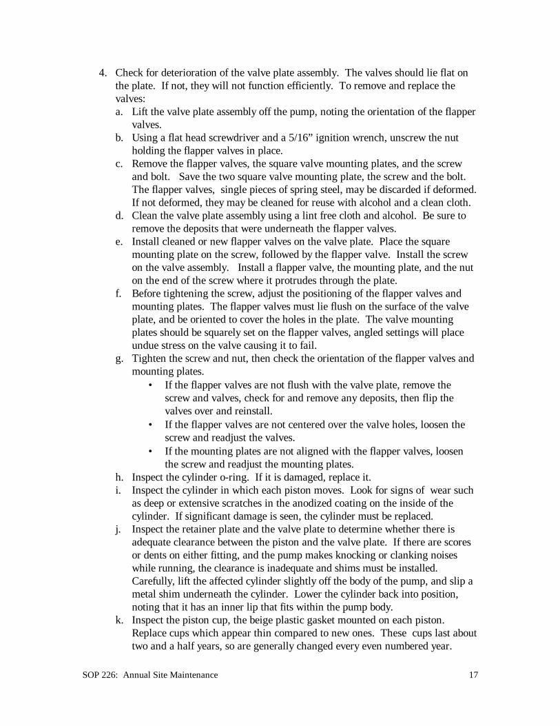
4. Check for deterioration of the valve plate assembly. The valves should lie flat onthe plate. If not, they will not function efficiently. To remove and replace thevalves:a. Lift the valve plate assembly off the pump, noting the orientation of the flapper
valves.b. Using a flat head screwdriver and a 5/16” ignition wrench, unscrew the nut
holding the flapper valves in place.c. Remove the flapper valves, the square valve mounting plates, and the screw
and bolt. Save the two square valve mounting plate, the screw and the bolt.The flapper valves, single pieces of spring steel, may be discarded if deformed.If not deformed, they may be cleaned for reuse with alcohol and a clean cloth.
d. Clean the valve plate assembly using a lint free cloth and alcohol. Be sure toremove the deposits that were underneath the flapper valves.
e. Install cleaned or new flapper valves on the valve plate. Place the squaremounting plate on the screw, followed by the flapper valve. Install the screwon the valve assembly. Install a flapper valve, the mounting plate, and the nuton the end of the screw where it protrudes through the plate.
f. Before tightening the screw, adjust the positioning of the flapper valves andmounting plates. The flapper valves must lie flush on the surface of the valveplate, and be oriented to cover the holes in the plate. The valve mountingplates should be squarely set on the flapper valves, angled settings will placeundue stress on the valve causing it to fail.
g. Tighten the screw and nut, then check the orientation of the flapper valves andmounting plates.
• If the flapper valves are not flush with the valve plate, remove thescrew and valves, check for and remove any deposits, then flip thevalves over and reinstall.
• If the flapper valves are not centered over the valve holes, loosen thescrew and readjust the valves.
• If the mounting plates are not aligned with the flapper valves, loosenthe screw and readjust the mounting plates.
h. Inspect the cylinder o-ring. If it is damaged, replace it.i. Inspect the cylinder in which each piston moves. Look for signs of wear such
as deep or extensive scratches in the anodized coating on the inside of thecylinder. If significant damage is seen, the cylinder must be replaced.
j. Inspect the retainer plate and the valve plate to determine whether there isadequate clearance between the piston and the valve plate. If there are scoresor dents on either fitting, and the pump makes knocking or clanking noiseswhile running, the clearance is inadequate and shims must be installed.Carefully, lift the affected cylinder slightly off the body of the pump, and slip ametal shim underneath the cylinder. Lower the cylinder back into position,noting that it has an inner lip that fits within the pump body.
k. Inspect the piston cup, the beige plastic gasket mounted on each piston.Replace cups which appear thin compared to new ones. These cups last abouttwo and a half years, so are generally changed every even numbered year.

SOP 226: Annual Site Maintenance 18
However, they are always inspected and, if badly worn, are replaced. Toreplace the cups,i. Using a Phillips screwdriver, unscrew the two screws on the retainer plate
of a piston. Use caution to avoid stripping the screws.• If one screw has been removed, but the other is stripped, angle the tip
of a large flat head screwdriver against the top edge of the hole fromthe removed screw. Hit the screwdriver with a hammer to shift theposition of the retainer plate, then move the plate back. This shouldloosen the stripped screw enough to allow removal. Be careful toavoid damaging the threads in the hole.
• If both screws are stuck and stripped, they must be drilled out. This ispreferably done in a shop, so the pump should be mailed back to theAir Quality Group. Replace the pump with one of the spare pumpstaken along during maintenance. If necessary, call the Air QualityGroup and request a replacement pump.
ii. Remove the retainer plate and the beige plastic cup.iii. Holding the cylinders in place, push the other piston to its lowest position,
thereby moving the piston being worked on into its highest position.iv. Install a new cup and screw the retaining plate down firmly to hold the cup
in place. Be sure the cup is centered under the retaining plate.v. Repeat steps i. through iv. for the other piston.
l. If it is not the scheduled replacement year for the cups, but the cups on onepump are severely worn, the technician shall check, and replace if necessary,the cups on the pump with the next highest vacuum change. Until a pump notrequiring new cups is found, the inspection and replacement process willcontinue.
m. Reassemble the pump.i. Verify that both cylinders are seated properly within the pump body.ii. Verify that the cylinder o-ring is in place and undamaged.iii. Install the head gaskets on the pump heads.iv. Install the valve plate assembly on the head gasket, aligning the plate such
that the flapper valve is positioned in the quarter circular opening in thegasket. With the valve plate assembly in this orientation, the small hole onthe edge of the plate should be aligned with the protrusion on the headbeneath the intake port. If it is not aligned, check the orientation of theflapper valve on the plate, and the positioning of the plate.
v. Flip the assembly created in step iv. over onto the remainder of the pump,noting that the air inlet side of the pump is opposite the electrical box andcapacitor.
vi. Verify that the alignment is correct, and tighten everything down with thesix bolts.
vii. Write the date that the pump was maintained on the top of the pump,removing the previous maintenance date.
n. Test the pump. Plug it in.

SOP 226: Annual Site Maintenance 19
• It should start promptly, if not, and there is something blocking the airinlet, verify that the pump is turned on and has power. If it still will notstart, take it apart again as something may be jammed.
• The pump should not make loud knocking noises. If it makes knockingor grinding noises, turn it off. Something was not assembled correctly,or it needs another shim.
• Attach a vacuum gauge to the pump. If the vacuum reading on thegauge has not improved , take the pump apart again, inspect it, andreassemble it. If the pump vacuum still reads more than 2” Hg lowerthan the other pumps at the site, label it as needing maintenance, andreplace the pump with a spare.
o. Once the pump is repaired, reconnect it to the vacuum line to the samplermodule and plug it into its switched outlet.
4.2.3.6 Inspect the Sampler Stand or Structure and the Sampling Modules.Look for deterioration of the stand or structure, noting it in the maintenance loop
note book. The modules should be securely attached to the mounting structure, andthe stacks should not move when the wind blows.
1. Repair loose joints with wood screws or lag bolts. Replace any structurallyunsound boards or beams.
2. Verify that all the modules are mounted securely, and that the stacks are stable,especially the D module stack. The D module stack, if it extends farther than3’ from any support may require guy lines to prevent excessive motion in thewind. However, before installing guy lines in pre-existing buildings, obtainpermission from the site manager. Also, for any building, if the guy lineanchors must be drilled into the building, be sure to seal the area well with roofcaulking to prevent water damage.a. The simplest guy line method for D modules having Sierra Anderson inlet
heads (Olympic torch shape) involves three guy lines running from pointson the roof or stand to the inlet head. The four posts on the SierraAnderson inlet are points for guy line connections.
b. D modules having Wedding inlets (mushroom shape) are more difficult toguy as the inlet provides no connection points. Bolt a pipe bracket aroundthe stack just below the inlet head and connect the guy lines to this bracket.As with the Sierra Anderson inlet, three guy lines are generally effective inreducing wind motion.
3. If the sampler is mounted inside a pre-existing building which is experiencingstructural problems, bring this to the attention of the manager of the buildingbefore attempting repairs.
4. Note the condition of the exterior of the modules. If fiberglass is coming offthe module, it must be repainted for protection. Repainting should be done asthe last step of annual maintenance, but only if no sampling will occur at thesite for at least twenty-four hours following the painting of the modules.Before painting the modules, complete all other facets of annual maintenance,

SOP 226: Annual Site Maintenance 20
including operator training and flow rate audits. Once annual maintenance hasbeen completed, perform the following:a. Gently sand the modules to be painted to remove loose fiberglass fibers.b. Prepare water based acrylic enamel paint in clear or slate gray for painting
the module.c. Cover all metal fittings, vents, and any equipment that may be sensitive to
the paint.d. If there is an ozone monitor at the site, do not use paint in aerosol cans,
instead, brush the paint on the modules.e. Paint the modules after all other site maintenance, flow rate audits, and
operator training procedures are completed.f. Do not paint the modules unless 24 hours of drying time prior to the next
sampling period are available.
4.2.3.7 Inspect and Clean the Pump House or Pump Area.For an outdoor site,1. Check the stability of the pump house, repair or add bracing as necessary.2. Brush out the pump house, removing all dirt, spider webs, insect populations, etc.3. Verify that the four hot power outlets in the pump house are all functional with a
voltmeter. If they are not functional, turn off the power at the breaker, then repairthe wiring.
4. For sites that are indoors and climate controlled, step 4 can be skipped. Foroutdoors or indoors sites without climate control, verify that the cooling fan isfunctioning; it should run if the temperature inside the pump house is higher than70°.a. If the temperature is over 90° and the fan is not functional, use a jumper wire
to bypass the thermostat for the fan.• If the fan starts, the thermostat must be replaced.• If the fan doesn’t start, check the power using a voltmeter. If there is
power, the fan is damaged and must be replaced.b. If the temperature is under 90° and the fan is not running, test the fan by using
a jumper wire to bypass the thermostat for the fan.• If the fan starts, it is functioning properly.• If the fan doesn’t start, check the power using a voltmeter. If there is
power, the fan is damaged and must be replaced.c. If the temperature is under 60° and the fan is running, the thermostat is
damaged and must be replaced.5. Verify that the switched outlets for the pump are functioning properly. When the
30 minute timer in a control module or the pump override switch in a controllermodule A are turned on, the pumps should turn on in sequence at 8 secondintervals. The sequence is Module A pump, followed by B, then C, then D. If twopumps come on at the same time, one of the timers is bad and must be replaced.
For an indoor site,1. Brush out the pump area, removing all dirt, spider webs, insect populations, etc.

SOP 226: Annual Site Maintenance 21
2. Verify that the switched outlets for the pump are functioning properly. When the30 minute timer in a control module or the pump override switch in a controllermodule A are turned on, the pumps should turn on in sequence at 8 secondintervals. The sequence is Module A pump, followed by B, then C, then D. If twopumps come on at the same time, one of the delay relays in the controller moduleor, at sites having controller module A’s, in the relay box, is bad and must bereplaced.
3. Verify that the pumps are in an area having enough air flow for effective cooling.If not, move or rearrange the pumps.
4.2.3.8 Inspect the Controller Module.For both controller modules and controller module A samplers, perform the following:1. Check the functioning of the cooling fan; is should run if the temperature inside
the module is higher than 70°.a. If the temperature in the module is between 70° and 90°, and the fan is not
functional, use a jumper wire to bypass the thermostat for the fan.• If the fan starts, for an A module controller, the thermostat must be
replaced.• If the fan starts for a controller module, the thermostat must be adjusted.
To adjust the thermostat in a controller module remove the plastic cover onthe thermostat and adjust the screw until the fan starts.
• If the fan doesn’t start, check the power using a voltmeter. If there ispower, the fan is damaged and must be replaced.
b. If the temperature in the module is below 60° and the fan is running,• For an A module controller, the thermostat must be replaced.• For a controller module, the thermostat must be adjusted. To adjust the
thermostat in a controller module remove the plastic cover on thethermostat and adjust the screw until the fan turns off.
2. Verify that the heater is functional. The heater should run if the temperatureapproaches freezing. Use a jumper wire to bypass the thermostat for the heater totest whether it is functional.a. If the temperature in the module is below 40° and the heater is not running,
• For an A module controller, the thermostat must be replaced.• For a controller module, the thermostat must be adjusted. To adjust the
thermostat in a controller module remove the plastic cover on thethermostat and adjust the screw until the heater starts.
• If the heater doesn’t start, check the power using a voltmeter. If there ispower, the heater is damaged and must be replaced.
b. If the temperature in the module is above 40° and the heater is running,• For an A module controller, the thermostat must be replaced.• For a controller module, the thermostat must be adjusted. To adjust the
thermostat in a controller module remove the plastic cover on thethermostat and adjust the screw until the heater turns off.

SOP 226: Annual Site Maintenance 22
3. Check the clock controller display, including the current time and day and thesampling programs. Reference TI 176D or SOP 176 section 4.3 for clockcontroller programs.
4. For controller modules, not module A controllers, remove the fuse in the lowerright corner, and leave the clock controller without power for at least 30 minutesto test the clock's internal batteries. If the clock looses the correct time, ormalfunctions while without power, replace it and return the bad clock to be fixed.Replace the fuse when the test is completed. Verify that there is a spare fuse forthe module taped to the wall.
5. For module A controllers, turn off the breaker switch on the heater manifold, toleave the clock controller without power for 30 minutes as a test of the clock'sinternal batteries. If the clock looses the correct time, or malfunctions whilewithout power, replace it with a new clock and return the bad clock to be repaired.Turn the breaker switch back on when the test is completed.
4.2.3.9 Reinstall the Cyclone Assemblies in the Sampling Modules.1. Carefully re-seat the cyclones in the stack inlet tee. Note that this is an o-ring fit
and should not be loose.2. Replace the two ¼-20 x ½” mounting screws, bolting them through the bottom of
the tee bracket into the cyclone body.3. Reattach the magnehelic hoses, verifying that the low pressure hose runs to the
nipple on the cyclone upper funnel and the high pressure hose runs to the nipple onthe back of the cyclone body. Recall also that the center port on the back of themagnehelic is the low pressure port while the port on the top is the high pressureport.
4. Install the audit filters on the cyclones.
4.2.3.10 Leak Check the Sampling Modules.1. To leak check modules A, B, and C,
a. Verify that the stack bottom plug is installed.b. Remove the inlet from the stack and install a rubber plug in the top of the
stack.c. With the annual maintenance audit cassettes installed, turn on the pumps, and
toggle open channel #1. After the system equilibrates, the pump vacuumshould be within 1"Hg of the reading with the solenoid closed, and themagnehelic reading should be 0.00”H2O. If the system behaves differently,there's a leak.
d. To locate this type of leak, check the fittings between the solenoid and the topof the stack Check each seal to be sure it is good; cassette to solenoid,cassette to manifold, black caps on manifold, magnehelic hoses(both ends ofboth hoses) and the brass nipple(s) they are attached to, manifold to cyclone,cyclone bottom funnel, cyclone cup, cyclone to inlet tee, inlet tee plug, andstack plug. A rarely seen, but possible cause for a leak is a crackedmagnehelic face.
e. Remove the rubber plug from the stack.

SOP 226: Annual Site Maintenance 23
f. Replace the inlet on the stack.2. For module D or D/S,
a. Remove the PM10 inlet from the stack and install a rubber plug in the top of thestack.
b. With the annual maintenance audit cassettes installed, turn on the pumps, andtoggle open channel #1. After the system equilibrates, the pump vacuumshould be within 1"Hg of the reading with the solenoid closed. If it isn't,there's a leak.
c. To locate this type of leak, check the fittings between the solenoid and the topof the stack Check each seal to be sure it is good; cassette to solenoid,cassette to manifold, black caps on manifold, magnehelic hoses(both ends ofboth hoses) and the brass nipple(s) they are attached to, manifold to funnel,funnel to stack, and the stack plug. A rarely seen, but possible cause for aleak is a cracked magnehelic face.
d. Remove the rubber plug from the stack.e. Replace the inlet on the stack.
4.2.3.11 D Module Flow Inspection.Verify that channels 1 and 2 in the D module are both accurately described by the
system calibration equations.1. Record the system magnehelic reading for the channel 1 and channel 2 annual
maintenance audit cassettes. They should match within 0.01” H2O. If the readingsdo not match, then either the orifice meter is too close to the solenoid manifold, orthe path lengths between the solenoids and the orifice meter are too unequal.a. If the orifice meter is not separated from the solenoid manifold brass pipe
extender fitting, this should be rectified.i. Turn off the sampler (turn the pump override timer of switch to “off” or
“auto”).ii. Remove the D module orifice meter by unscrewing it from the manifold.iii. Install the male end of the pipe extender fitting in the solenoid manifold,
using a small amount of Teflon plumbers tape.iv. Thread the male end of the orifice meter into the pipe extender.v. Verify that the female end of the orifice meter is connected to the
CAJON VCO female connector.vi. Check the system for leaks, following the procedures in section 4.2.3.10.vii. Turn the sampler and pumps back on using the 30 minute timer or the
pump override switch.viii. Test the two channels again to determine whether the readings match. If
not, try step b.b. If the orifice meter is separated from the manifold by the pipe extender fitting,
but the readings on the two solenoids still do not match,i. Turn off the sampler (turn the pump override timer or switch to “off” or
“auto’)

SOP 226: Annual Site Maintenance 24
ii. Remove one solenoid by unscrewing the two screws and nuts holding it tothe solenoid manifold mounting plate. The solenoid is held in place by ano-ring fitting. Pull the solenoid straight out to remove it.
iii. Check the o-ring on the solenoid. If it is worn or damaged, replace it. Itshould be lightly greased with vacuum grease.
iv. Move the solenoid to a position on the manifold where it appears that bothsolenoids will be more equally spaced from the orifice meter.
v. Install the solenoid by pressing it into position to ensure an o-ring fit, thenreinstalling the screws and nuts.
vi. Turn the sampler and pumps back on using the 30 minute timer or thepump override switch.
vii. Check the system for leaks, following the procedures in section 4.2.3.10.viii. Record the readings from the two channels. If they still do not agree,
perform step b again, moving the solenoids to different positions.
4.2.4 Sampler CalibrationThe procedures for sampler calibration are covered in detail in TI 176C. Merely notethat the final audit performed at the site shall be used to derive the calibration equationfor the module.
4.2.5 Post Calibration Check1. Perform operator training and review, as described in section 4.3.2. Reinstall the current week’s cassettes and cyclone port covers.3. Verify that the stack bottom plugs are all securely installed.4. Record the new initial readings for cassettes that have not yet collected a sample
on the current week's log sheet. If the log sheet is not available, record the valuesin the site notebook, and on a sheet of paper to be left in the controller module forthe site operator.
5. Start the current sample if one is supposed to be running by pressing theappropriate channel on the top row of override buttons on the clock controller.Note the restart time on the log sheet.
6. Check all fittings, stacks, inlets, etc. to verify nothing has been left out of place.7. If the site is run by a controller module, be sure fuse is back in place.8. Close the module doors and lock them, or lock the building in which they are kept.9. Clean the area of the trash generated by sampler maintenance.10. Leave a note for the site operators if they could not be contacted describing what
changes were made to the site.11. Paint the modules, if necessary, following the procedures in section 4.2.3.4 part 4.
4.3 Operator Training and ReviewSite operator training involves review of the materials covered in TI 201A, IMPROVEAerosol Sampler Operation Manual. The site operator must be trained to perform thefollowing tasks:

SOP 226: Annual Site Maintenance 25
1. Recording of the final readings for exposed filter cassettes.2. Removal of exposed filter cassettes.3. Installation of clean filter cassettes.4. Recording of initial readings for the clean filter cassettes.5. Mailing procedures for the return of exposed filter cassettes and log sheets.6. Air Quality Group phone numbers; where to find them and when to call.7. Programming the clock controller
a. Setting current timeb. Reading the installed programsc. Writing new programsd. Erasing unwanted programse. Where to find IMPROVE clock controller programs in the operators manual
8. Basic troubleshooting procedures for anomalous gauge readings.9. Overview of the site audit procedure, in preparation for the biannual audit.