Embed Size (px)
DESCRIPTION
Service manual v1.4 Lev2 des cameras .13013Ko.212p
Citation preview
Input/outputconnectors
S video input/output4-pin mini DINLuminance signal: 1 Vp-p,75 Ω (ohms), unbalancedChrominance signal: 0.3 Vp-p,75 Ω (ohms), unbalancedAudio/Video input/outputAV MINIJACK, 1 Vp-p, 75 Ω(ohms), unbalanced, sync negative327 mV, (at output impedance morethan 47 kΩ (kilohms))Output impedance with less than2.2 kΩ (kilohms)/Stereo minijack(ø 3.5 mm)Input impedance more than 47 kΩ(kilohms)Headphone jackStereo minijack (ø 3.5 mm)USB jackmini-B
LANC jackStereo mini-minijack (ø 2.5 mm)MIC jackStereo minijack (ø 3.5 mm)DV input/output4-pin connector
LCD screen
Picture6.2 cm (2.5 type)50.3 × 37.4 mm (2 × 1 1/2 in.)Total dot numberFor European models:123 200 (560 × 220)For other countries’ models:61 600 (280 × 220)
Video camerarecorder
System
Video recording system2 rotary headsHelical scanning systemAudio recording systemRotary heads, PCM systemQuantization: 12 bits (Fs 32 kHz,stereo 1, stereo 2), 16 bits(Fs 48 kHz, stereo)Video signalPAL colour, CCIR standardsRecommended cassetteHi8/Digital8 video cassetteRecording/playback time (using90 min. Hi8 video cassette)SP mode: 1 hourLP mode: 1 hour and 30 minutesFast-forward/rewind time (using90 min. Hi8 video cassette)Approx. 5 min.ViewfinderElectric Viewfinder, Monochrome
Image device3 mm (1/6 type CCD)(Charge Coupled Device)Gross: Approx. 800 000 pixelsEffective: Approx. 400 000 pixelsLensCombined power zoom lensFilter diameter 37 mm (1 1/2 in.)25× (Optical), 700× (Digital)Focal length2.4 – 60 mm (1/8 – 2 3/8 in.)When converted to a 35 mm stillcamera46 – 1 150 mm (1 13/16 – 45 3/8 in.)Colour temperatureAutoMinimum illumination6 lx (lux) (F 1.6)0 lx (lux) (in the NightShot mode)** Objects unable to be seen due to
the dark can be shot with infraredlighting.
SERVICE MANUAL
M2000 MECHANISM
DIGITAL VIDEO CAMERA RECORDER
SPECIFICATIONS
Photo : DCR-TRV240E
— Continued on next page —
DCR-TRV240E/TRV340ERMT-814
AEP ModelUK Model
E ModelHong Kong ModelAustralian Model
East European ModelNorth European Model
Russian ModelDCR-TRV240E/TRV340E
Chinese ModelTourist Model
DCR-TRV340E
Level 2
Ver 1.4 2003. 04
For MECHANISM ADJUSTMENT, refer to the“8mm Video MECHANICAL ADJUSTMENTMANUAL IX M2000 MECHANISM ” (9-929-861-11).
On the VC-276 boardThis service manual provides the information that is premised thecircuit board replacement service and not intended repair inside theVC-276 board.Therefore, schematic diagram, printed wiring board, waveforms,mounted parts location and electrical parts list of the VC-276 boardare not shown.The following pages are not shown.
Schematic diagram .....................................Pages 4-37 to 4-86Printed wiring board ....................................Pages 4-87 to 4-90Waveforms and mounted parts location .....Pages 4-93 to 4-97Electrical parts list .......................................Pages 6-15 to 6-26
— 2 —
SAFETY-RELATED COMPONENT WARNING!!
COMPONENTS IDENTIFIED BY MARK 0 OR DOTTED LINE WITHMARK 0 ON THE SCHEMATIC DIAGRAMS AND IN THE PARTSLIST ARE CRITICAL TO SAFE OPERATION. REPLACE THESECOMPONENTS WITH SONY PARTS WHOSE PART NUMBERSAPPEAR AS SHOWN IN THIS MANUAL OR IN SUPPLEMENTSPUBLISHED BY SONY.
DCR-TRV240E/TRV340E
1. Check the area of your repair for unsoldered or poorly-solderedconnections. Check the entire board surface for solder splashesand bridges.
2. Check the interboard wiring to ensure that no wires are"pinched" or contact high-wattage resistors.
3. Look for unauthorized replacement parts, particularlytransistors, that were installed during a previous repair. Pointthem out to the customer and recommend their replacement.
4. Look for parts which, through functioning, show obvious signsof deterioration. Point them out to the customer andrecommend their replacement.
5. Check the B+ voltage to see it is at the values specified.6. Flexible Circuit Board Repairing
• Keep the temperature of the soldering iron around 270˚Cduring repairing.
• Do not touch the soldering iron on the same conductor of thecircuit board (within 3 times).
• Be careful not to apply force on the conductor when solderingor unsoldering.
Unleaded solderBoards requiring use of unleaded solder are printed with the lead-free mark (LF) indicating the solder contains no lead.(Caution: Some printed circuit boards may not come printed withthe lead free mark due to their particular size.)
: LEAD FREE MARKUnleaded solder has the following characteristics.• Unleaded solder melts at a temperature about 40°C higher than
ordinary solder.Ordinary soldering irons can be used but the iron tip has to beapplied to the solder joint for a slightly longer time.Soldering irons using a temperature regulator should be set toabout 350°C.Caution: The printed pattern (copper foil) may peel away if theheated tip is applied for too long, so be careful!
• Strong viscosityUnleaded solder is more viscous (sticky, less prone to flow) thanordinary solder so use caution not to let solder bridges occur suchas on IC pins, etc.
• Usable with ordinary solderIt is best to use only unleaded solder but unleaded solder mayalso be added to ordinary solder.
SAFETY CHECK-OUT
After correcting the original service problem, perform the following
safety checks before releasing the set to the customer.
CAUTION :Danger of explosion if battery is incorrectly replaced.Replace only with the same or equivalent type.
AC power adaptor
Power requirements100 – 240 V AC, 50/60 HzPower consumption23 WOutput voltageDC OUT: 8.4 V, 1.5 A in theoperating modeOperating temperature0°C to 40°C (32°F to 104°F)Storage temperature–20°C to + 60°C (–4°F to + 140°F)Dimensions (approx.)125 × 39 × 62 mm(5 × 1 9/16 × 2 1/2 in. ) (w/h/d)excluding projecting partsMass (approx.)280 g (9.8 oz)excluding mains lead
Battery pack
Maximum output voltageDC 8.4 VMean output voltageDC 7.2 VCapacity5.0 Wh (700 mAh)Operating temperature0°C to 40°C (32°F to 104°F)Dimensions (approx.)38.2 × 20.5 × 55.6 mm(1 9/16 × 13/16 × 2 1/4 in.)(w/h/d)Mass (approx.)65 g (2.3 oz)TypeLithium ion
“Memory Stick”
(DCR-TRV340E only)MemoryFlash memory8MB: MSA-8AOperating voltage2.7 – 3.6 VPower consumptionApprox. 45 mA in the operatingmodeApprox. 130 µA in the standbymodeDimensions (approx.)50 × 2.8 × 21.5 mm(2 × 1/8 × 7/8 in.) (w/h/d)Mass (approx.)4 g (0.14 oz)
Design and specifications aresubject to change without notice.
General
Power requirements7.2 V (battery pack)8.4 V (AC power adaptor)Average power consumption(when using the battery pack)During camera recording usingLCD3.8 WViewfinder3.0 WOperating temperature0°C to 40°C (32°F to 104°F)Recommended chargingtemperature10°C to 30°C (50°F to 86°F)Storage temperature–20°C to + 60°C (–4°F to + 140°F)Dimensions (approx.)206 × 101 × 85 mm(8 1/8 × 4 × 3 3/8 in.)(w/h/d)Mass (approx.)DCR-TRV240E:890 g (1 lb 15 oz)DCR-TRV340E:900 g (1 lb 15 oz)excluding the battery pack, cassette,lens cap and shoulder strap
DCR-TRV240E:1 030 g (2 lb 4 oz)DCR-TRV340E:1 040 g (2 lb 4 oz)including the battery packNP-FM30, 90min. Hi8 cassette, lenscap and shoulder strapSupplied accessoriesSee page 3.

— 3 —
DCR-TRV240E/TRV340E
• SUPPLIED ACCESSORIESMake sure that the following accessories are supplied with your camcorder.
1Wireless Remote Commander (1)
2AC-L10A/L10B/L10C AC power adaptor (1),Mains lead (1)
3NP-FM30 battery pack (1)
4 R6 (size AA) battery for RemoteCommander (2)
5A/V connecting cable (1)
6 Shoulder strap (1)
7 Lens cap (1)
8USB cable (1)
9 “Memory Stick” (MSA-8A) (1) (DCR-TRV340E only)
0 CD-ROM (SPVD-008 USB Driver) (1)
qa 21-pin adaptor (1)
(1)
(1)
(European models only)
qs 2-pin conversion adaptor DCR-TRV340E: Tourist model only
qd 2-pin conversion adaptor DCR-TRV240E: E, Hong Kong/TRV340E: E, Hong Kong models only
1 2
4 5 6 7
3
8 9
qs qd
0 qa

— 4 —
DCR-TRV240E/TRV340E
TABLE OF CONTENTSSERVICE NOTE1. POWER SUPPLY DURING REPAIRS ····························· 72. TO TAKE OUT A CASSETTE WHEN NOT EJECT
(FORCE EJECT) ································································ 7
SELF-DIAGNOSIS FUNCTION1. Self-diagnosis Function ······················································ 82. Self-diagnosis Display ························································ 83. Service Mode Display ························································ 83-1. Display Method ·································································· 83-2. Switching of Backup No. ··················································· 83-3. End of Display ···································································· 84. Self-diagnosis Code Table ·················································· 9
1. GENERALMain features ·············································································1-1Quick Start Guide ······································································ 1-1Getting Started
Using this manual ·································································· 1-2Checking supplied accessories ·············································· 1-2Step 1 Preparing the power supply ········································1-3 Installing the battery pack ··················································· 1-3 Charging the battery pack ··················································· 1-3 Connecting to a wall socket ················································1-4Step 2 Setting the date and time ············································1-4Step 3 Inserting a cassette ······················································ 1-5
Recording – BasicsRecording a picture ································································1-5 Shooting backlit subjects – BACK LIGHT ························ 1-7 Shooting in the dark – NightShot/Super NightShot/ Colour Slow Shutter ··························································· 1-7 Self-timer recording (DCR-TRV340E only) ······················ 1-8Checking recordings – END SEARCH/EDITSEARCH/Rec Review ·················································· 1-8
Playback – BasicsPlaying back a tape ································································1-9 To display the screen indicators – Display function ··········· 1-9Viewing recordings on TV ···················································1-10
Advanced Recording OperationsRecording still images on a tape – Tape Photo recording ····1-11Using the wide mode ···························································1-12Using the fader function ······················································1-12Using special effects – Picture effect ···································1-13Using special effects – Digital effect ···································1-14Using the PROGRAM AE function ·····································1-14Adjusting the exposure manually ········································1-15Focusing manually ·······························································1-15Interval recording ·································································1-16Frame by frame recording – Frame recording ·····················1-16Superimposing a title ···························································1-17Making your own titles ························································1-18Inserting a scene ··································································1-18
Advanced Playback OperationsPlaying back tapes with picture effects ································1-19Playing back tapes with digital effects ································1-19Enlarging recorded images – Tape PB ZOOM ····················1-20Quickly locating a scene – ZERO SET MEMORY ·············1-20Searching a recording by date – DATE SEARCH ···············1-20Searching for a photo– PHOTO SEARCH/PHOTO SCAN ···································1-21
EditingDubbing a tape ·····································································1-21Dubbing only desired scenes – Digital program editing(on tapes) ·············································································1-22Capturing images from an analog video uniton your computer – Signal convert function ························1-27
Recording video or TV programmes ···································1-27Inserting a scene from a VCR – Insert Editing ····················1-28Viewing images recorded on a tape onyour computer (Windows users only) ··································1-29
Customizing Your CamcorderChanging the menu settings ·················································1-32
“Memory Stick” operations (DCR-TRV340E only)Using “Memory Stick” – Introduction ································1-35Recording still images on “MemoryStick”s– Memory Photo recording ··················································1-37Superimposing a still image in the“Memory Stick” on an image – MEMORY MIX ··········································1-39Recording images from a tape as still images ·····················1-41Copying still images from a tape – PHOTO SAVE ·············1-42Recording moving pictures on “Memory Stick”s– MPEG movie recording ····················································1-42Recording pictures from a tape as moving pictures ·············1-43Recording edited pictures as a moving picture– Digital program editing (on “Memory Stick”s) ················1-44Viewing still images – Memory Photo playback ·················1-45Viewing moving pictures – MPEG movie playback ············1-46Viewing images recorded on “Memory Stick”son your computer ·································································1-47Copying images recorded on “Memory Stick”s to tape ······1-50Enlarging still images recorded on “Memory Stick”s– Memory PB ZOOM ··························································1-50Playing back images in a continuous loop– SLIDE SHOW ··································································1-51Preventing accidental erasure – Image protection ···············1-51Deleting images – DELETE ················································1-52Writing a print mark – PRINT MARK ································1-52Using the optional printer ····················································1-53
TroubleshootingTypes of trouble and how to correct trouble ························1-53Self-diagnosis display ··························································1-55Warning indicators and messages ········································1-55
Additional InformationDigital8 system, recording and playback ························1-56About the “InfoLITHIUM” battery pack ·····························1-57About i.LINK ·······································································1-57Using your camcorder abroad ··············································1-58Maintenance information and precautions ···························1-58
Quick ReferenceIdentifying parts and controls ··············································1-60
2. DISASSEMBLY2-1. LCD UNIT, PD-156/160 BOARD ·································· 2-22-2. FRONT PANEL SECTION, SI-032 BOARD ·················2-32-3. CABINET (R) SECTION ···············································2-42-4. LENS SECTION, CD-357 BOARD ·······························2-52-5. EVF SECTION, LB-076 BOARD ·································· 2-62-6. BATTERY PANEL SECTION, BATTERY TERMINAL
BOARD ···········································································2-72-7. MEMORY STICK 10P CONNECTOR
(MEMORY STICK MODEL) (TRV340E) ·····················2-72-8. CONTROL SWITCH BLOCK (SS-1380) ······················ 2-82-9. CABINET (L) SECTION, CS FRAME ASSEMBLY (25) · 2-82-10. VC-276 BOARD ·····························································2-92-11. MECHANISM DECK ·····················································2-92-12. CONTROL SWITCH BLOCK (CF-2500) ···················2-122-13. CONTROL SWITCH BLOCK (FK-2500) ···················2-122-14. HINGE SECTION ·························································2-132-15. CIRCUIT BOARDS LOCATION ·································2-142-16. FLEXIBLE BOARDS LOCATION ······························2-15
— 5 —
DCR-TRV240E/TRV340E
3. BLOCK DIAGRAMS3-1. OVERALL BLOCK DIAGRAM (1/5) ···························3-13-2. OVERALL BLOCK DIAGRAM (2/5) ···························3-33-3. OVERALL BLOCK DIAGRAM (3/5) ···························3-53-4. OVERALL BLOCK DIAGRAM (4/5) ···························3-73-5. OVERALL BLOCK DIAGRAM (5/5) (DCR-TRV240E) ··· 3-93-5. OVERALL BLOCK DIAGRAM (5/5) (DCR-TRV340E) · 3-113-6. POWER BLOCK DIAGRAM (1/3) ······························ 3-133-7. POWER BLOCK DIAGRAM (2/3) ······························ 3-153-8. POWER BLOCK DIAGRAM (3/3) ······························ 3-17
4. PRINTED WIRING BOARDS ANDSCHEMATIC DIAGRAMS
4-1. FRAME SCHEMATIC DIAGRAM (1/2) ·······················4-1FRAME SCHEMATIC DIAGRAM (2/2) ·······················4-3
4-2. PRINTED WIRING BOARDS ANDSCHEMATIC DIAGRAMS ············································4-5• CD-357 (CCD IMAGER)
PRINTED WIRING BOARD ANDSCHEMATIC DIAGRAM ······························4-7
• LB-076 (EVF, BACK LIGHT)PRINTED WIRING BOARD ANDSCHEMATIC DIAGRAM ······························4-9
• SI-032 (STEADY SHOT, LASER LINK)PRINTED WIRING BOARD ······················· 4-11
• FP-411 FLEXIBLE BOARD ·····································4-12• SI-032 (STEADY SHOT, LASER LINK)
SCHEMATIC DIAGRAM ····························4-13• PD-156 (LCD DRIVER, BACKLIGHT, DRIVER,TIMING GENERATOR)
PRINTED WIRING BOARD ······················· 4-15• FP-412 FLEXIBLE BOARD ·····································4-18• PD-156 (LCD DRIVER, BACKLIGHT)(1/2)
SCHEMATIC DIAGRAM ····························4-19• PD-156 (DRIVER, TIMING GENERATOR)(2/2)
SCHEMATIC DIAGRAM ····························4-21• PD-160 (CHA, DISPLAY DRIVE, BACK LIGHT, LCDDRIVE, TG)
PRINTED WIRING BOARD ······················· 4-23• PD-160 (CHA, DISPLAY DRIVE, BACK LIGHT)(1/2)
SCHEMATIC DIAGRAM ····························4-27• PD-160 (LCD DRIVE, TG)(2/2)
SCHEMATIC DIAGRAM ····························4-29• CONTROL SWITCH BLOCK (CF-2500, FK-2500)
SCHEMATIC DIAGRAM ····························4-31• LS-057 (S/T REEL SENSOR), FP-228 (DEW SENSOR),FP-299 (MODE SWITCH), FP-300 (TAPE TOP),FP-302 (TAPE END), FP-301 (TAPE LED)
FLEXIBLE BOARDS ANDSCHEMATIC DIAGRAMS ·························· 4-33
• CONTROL SWITCH BLOCK (SS-1380)SCHEMATIC DIAGRAM ····························4-35
• FP-410 FLEXIBLE BOARD ·····································4-36
Shematic diagram and printed wiring board of theVC-276 board are not shown.Pages from 4-37 to 4-90 are not shown.
4-3. WAVEFORMS ······························································ 4-91
Waveforms and mounted parts location of theVC-276 board are not shown.Pages from 4-93 to 4-97 are not shown.
4-4. MOUNTED PARTS LOCATION ·································4-98
5. ADJUSTMENTS1. Adjusting items when replacing main parts and boards. ·5-25-1. CAMERA SECTION ADJUSTMENT ···························5-41-1. PREPARATIONS BEFORE ADJUSTMENT
(CAMERA SECTION) ···················································5-41-1-1.List of Service Tools ························································5-41-1-2.Preparations ·····································································5-51-1-3.Precaution ········································································5-71. Setting the Switch ····························································5-72. Order of Adjustments ······················································5-73. Subjects ···········································································5-71-2. INITIALIZATION OF 8, A, B, C, D, E, F, 1B, 1C, 1F
PAGE DATA ····································································5-81-2-1. INITIALIZATION OF D PAGE DATA (DCR-TRV240E) 5-91. Initializing the D Page Data ············································5-92. Modification of D Page Data ···········································5-93. D Page Table ····································································5-91-2-2. INITIALIZATION OF A, D PAGE DATA
(DCR-TRV340E) ···························································5-101. Initializing the A, D Page Data ······································ 5-102. Modification of A, D Page Data ····································5-103. D Page Table ·································································· 5-104. A Page Table ·································································· 5-101-2-3. INITIALIZATION OF B, 1B PAGE DATA
(DCR-TRV340E) ···························································5-111. Initializing the B, 1B Page Data ····································5-112. Modification of B, 1B Page Data ·································· 5-113. Loader writing inhibit mode setting ······························ 5-114. B Page Table ·································································· 5-115. 1B Page Table ································································5-111-2-4. INITIALIZATION OF 8, C, 1C PAGE DATA ·············· 5-121. Initializing the 8, C, 1C Page Data ································5-122. Modification of 8, C, 1C Page Data ······························ 5-123. C Page Table ·································································· 5-124. 8 Page Table ···································································5-145. 1C Page Table ································································5-141-2-5. INITIALIZATION OF E, F, 1F PAGE DATA ···············5-161. Initializing the E, F, 1F Page Data ·································5-162. Modification of E, F, 1F Page Data ·······························5-163. F Page Table ·································································· 5-164. E Page Table ·································································· 5-175. 1F Page Table ································································5-181-3. CAMERA SYSTEM ADJUSTMENTS ························5-191. HALL Adjustment ·························································5-192. Flange Back Adjustment (Using Minipattern Box) ·······5-203. Flange Back Adjustment (Using Flange Back Adjustment
Chart and Subject More Than 500m Away) ·················· 5-213-1. Flange Back Adjustment (1) ·········································· 5-213-2. Flange Back Adjustment (2) ·········································· 5-214. Flange Back Check ························································5-225. Optical Axis Adjustment ···············································5-236. Picture Frame Setting ····················································5-247. Color Reproduction Adjustment ····································5-258. Auto White Balance & LV Standard Data Input ···········5-259. Auto White Balance Adjustment ···································5-2610. White Balance Check ····················································5-2711. Steady Shot Check ·························································5-281-4. ELECTRONIC VIEWFINDER SYSTEM
ADJUSTMENT ·····························································5-291. VCO Adjustment (VC-276 board) ································5-292. RGB AMP Adjustment (VC-276 board) ·······················5-303. Contrast Adjustment (VC-276 board) ···························5-301-5. LCD SYSTEM ADJUSTMENT ···································5-311-5-1.LCD SYSTEM ADJUSTMETNT (LCD TYPE SO)
(PD-160 board) ······························································ 5-311. VCO Adjustment (PD-160 board) ·································5-31
— 6 —
DCR-TRV240E/TRV340E
2. PSIG Gray Adjustment (PD-160 board) ························5-323. RGB AMP Adjustment (PD-160 board) ························5-324. Black Limit Adjustment (PD-160 board) ······················ 5-335. Contrast Adjustment (PD-160 board) ····························5-336. Center Level Adjustment (PD-160 board) ·····················5-347. V-COM Adjustment (PD-160 board) ····························5-348. White Balance Adjustment (PD-160 board) ·················· 5-351-5-2.LCD SYSTEM ADJUSTMETNT (LCD TYPE SH)
(PD-156 board) ······························································5-361. VCO Adjustment (PD-156 board) ·································5-362. RGB AMP Adjustment (PD-156 board) ························5-373. Contrast Adjustment (PD-156 board) ····························5-374. COM AMP Adjustment (PD-156 board) ·······················5-385. V-COM Adjustment (PD-156 board) ····························5-386. White Balance Adjustment (PD-156 board) ·················· 5-395-2. MECHANISM SECTION ADJUSTMENT ·················· 5-402-1. Hi8/STANDARD 8 MODE ···········································5-402-1-1.OPERATING WITHOUT CASSETTE ························5-402-1-2.TAPE PATH ADJUSTMENT ········································5-401. Preparations for Adjustment ··········································5-402-2. DIGITAL8 MODE ························································5-412-2-1.HOW TO ENTER RECORD MODE WITHOUT
CASSETTE ···································································5-412-2-2.HOW TO ENTER PLAYBACK MODE WITHOUT
CASSETTE ···································································5-412-2-3.OVERALL TAPE PATH CHECK ·································5-411. Recording of the tape path check signal ························5-412. Tape path check ·····························································5-415-3. VIDEO SECTION ADJUSTMENT ······························5-423-1. PREPARATIONS BEFORE ADJUSTMENTS ············5-423-1-1.Equipment to Required ··················································5-423-1-2.Precautions on Adjusting ···············································5-433-1-3.Adjusting Connectors ····················································5-443-1-4.Connecting the Equipment ············································5-443-1-5.Alignment Tape ·····························································5-453-1-6. Input/output Level and Impedance ································5-453-2. SYSTEM CONTROL SYSTEM ADJUSTMENT ········5-461. Initialization of 8, A, B, C, D, E, F, 1B, 1C, 1F Page Data · 5-462. Serial No. Input ·····························································5-462-1. Company ID Input ·························································5-462-2. Serial No. Input ·····························································5-463-3. SERVO AND RF SYSTEM ADJUSTMENT ···············5-481. REEL FG Adjustment (VC-276 board) ·························5-482. PLL f0 & LPF f0 Adjustment (VC-276 board) ·············· 5-483. Switching Position Adjustment (VC-276 board) ···········5-494. AGC Center Level and APC & AEQ Adjustment ·········5-494-1. Preparations before adjustments ····································5-494-2. AGC Center Level Adjustment (VC-276 board) ···········5-494-3. APC & AEQ Adjustment (VC-276 board) ····················5-504-4. Processing after Completing Adjustments ····················5-505. PLL f0 & LPF f0 Fine Adjustment (VC-276 board) ······ 5-516. Hi8/Standard8 Switching Position Adjustment
(VC-276 board) ·····························································5-517. CAP FG Duty Adjustment (VC-276 board) ·················· 5-523-4. VIDEO SYSTEM ADJUSTMENTS ·····························5-531. 36MHz Origin Oscillation Adjustment (VC-276 board) ·· 5-532. S VIDEO OUT Y Level Adjustment (VC-276 board) ···5-533. S VIDEO OUT Chroma Level Adjustment
(VC-276 board) ·····························································5-544. VIDEO OUT Y, Chroma Level Check (VC-276 board) ·· 5-545. Hi8/Standard8 Y/C Output Level Setting
(VC-276 board) ·····························································5-556. Hi8/standard 8mm AFC f0 Adjustment (VC-276 board) · 5-553-5. AUDIO SYSTEM ADJUSTMENTS ····························5-561. Hi8/Standard8 AFM BPF f0 Adjustment (VC-276 board) · 5-562. Hi8/Standard8 AFM 1.5 MHz Deviation Adjustment
(VC-276 board) ·····························································5-57
3. Hi8/Standard8 AFM 1.7 MHz Deviation Adjustment(VC-276 board) ·····························································5-57
4. Digital8 Playback Level Check ·····································5-575. Overall Level Characteristics Check ·····························5-576. Overall Distortion Check ···············································5-577. Overall Noise Level Check ············································5-588. Overall Separation Check ··············································5-585-4. SERVICE MODE ··························································5-594-1. ADJUSTMENT REMOTE COMMANDER ················5-591. Using the Adjustment Remote Commander ··················5-592. Precautions Upon Using the Adjustment Remote
Commander ···································································5-594-2. DATA PROCESS ···························································5-604-3. SERVICE MODE ··························································5-611. Setting the Test Mode ····················································5-612. Emergence Memory Address ········································5-612-1. EMG Code (Emergency Code) ·····································5-612-2. MSW Code ····································································5-623. Bit Value Discrimination ···············································5-634. Switch check (1) ····························································5-635. Switch check (2) ····························································5-646. Switch check (3) ····························································5-647. Switch check (4) ····························································5-658. Record of Use check (1) ················································5-669. Record of Use check (2) ················································5-6610. Record of Self-diagnosis check ·····································5-67
6. REPAIR PARTS LIST6-1. EXPLODED VIEWS ······················································ 6-16-1-1.OVERALL SECTION ·····················································6-16-1-2.CABINET (L) SECTION-1 ············································6-26-1-3.CABINET (L) SECTION-2 ············································6-36-1-4.LENS, EVF SECTION ····················································6-46-1-5.CABINET (R) SECTION ···············································6-56-1-6.LCD SECTION ·······························································6-66-1-7.CASSETTE COMPARTMENT ASSY, DRUM ASSY ···6-76-1-8.LS CHASSIS BLOCK ASSEMBLY ·······························6-86-1-9.MECHANICAL CHASSIS BLOCK ASSEMBLY-1 ······ 6-96-1-10. MECHANICAL CHASSIS BLOCK ASSEMBLY-2 ··6-106-2. ELECTRICAL PARTS LIST ········································6-11
Parts list of the VC-276 board are not shown.Pages from 6-15 to 6-26 are not shown.
* Optical axis frame and Color reproduction frame areshown on pages 232 and 233.
— 7 —
DCR-TRV240E/TRV340ESERVICE NOTE
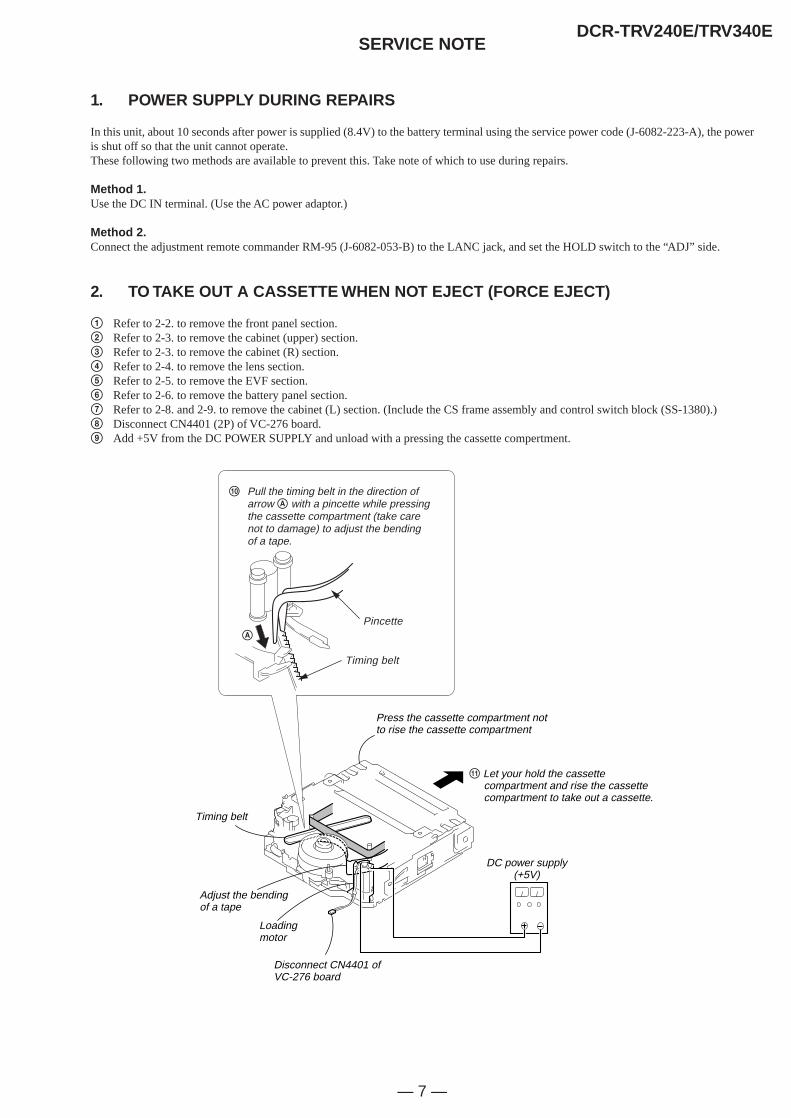
1. POWER SUPPLY DURING REPAIRS
In this unit, about 10 seconds after power is supplied (8.4V) to the battery terminal using the service power code (J-6082-223-A), the poweris shut off so that the unit cannot operate.These following two methods are available to prevent this. Take note of which to use during repairs.
Method 1.Use the DC IN terminal. (Use the AC power adaptor.)
Method 2.Connect the adjustment remote commander RM-95 (J-6082-053-B) to the LANC jack, and set the HOLD switch to the “ADJ” side.
2. TO TAKE OUT A CASSETTE WHEN NOT EJECT (FORCE EJECT)
1 Refer to 2-2. to remove the front panel section.2 Refer to 2-3. to remove the cabinet (upper) section.3 Refer to 2-3. to remove the cabinet (R) section.4 Refer to 2-4. to remove the lens section.5 Refer to 2-5. to remove the EVF section.6 Refer to 2-6. to remove the battery panel section.7 Refer to 2-8. and 2-9. to remove the cabinet (L) section. (Include the CS frame assembly and control switch block (SS-1380).)8 Disconnect CN4401 (2P) of VC-276 board.9 Add +5V from the DC POWER SUPPLY and unload with a pressing the cassette compertment.
qa Let your hold the cassette compartment and rise the cassette compartment to take out a cassette.
DC power supply(+5V)
Loading motor
Adjust the bending of a tape
Timing belt
Press the cassette compartment not to rise the cassette compartment
Disconnect CN4401 of VC-276 board
0 Pull the timing belt in the direction of arrow A with a pincette while pressing the cassette compartment (take care not to damage) to adjust the bending of a tape.
Pincette
Timing belt
A
— 8 —
DCR-TRV240E/TRV340ESELF-DIAGNOSIS FUNCTION
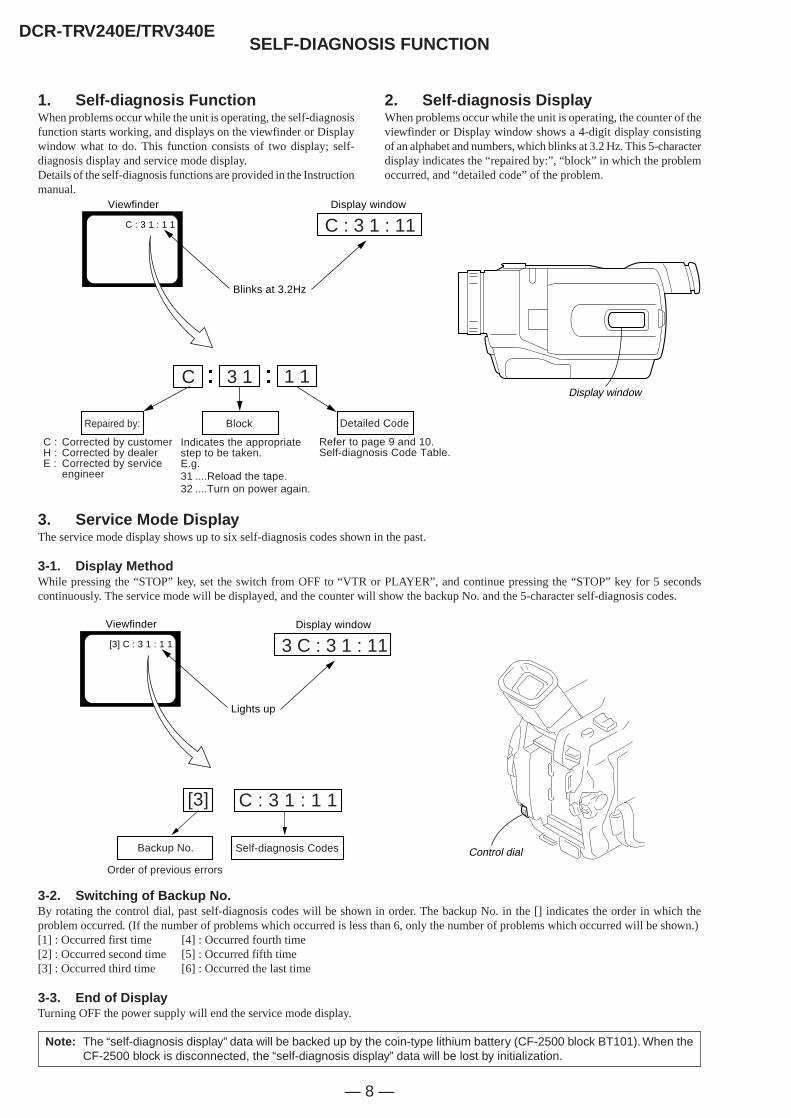
1. Self-diagnosis FunctionWhen problems occur while the unit is operating, the self-diagnosisfunction starts working, and displays on the viewfinder or Displaywindow what to do. This function consists of two display; self-diagnosis display and service mode display.Details of the self-diagnosis functions are provided in the Instructionmanual.
Note: The “self-diagnosis display” data will be backed up by the coin-type lithium battery (CF-2500 block BT101). When theCF-2500 block is disconnected, the “self-diagnosis display” data will be lost by initialization.
2. Self-diagnosis DisplayWhen problems occur while the unit is operating, the counter of theviewfinder or Display window shows a 4-digit display consistingof an alphabet and numbers, which blinks at 3.2 Hz. This 5-characterdisplay indicates the “repaired by:”, “block” in which the problemoccurred, and “detailed code” of the problem.
3. Service Mode DisplayThe service mode display shows up to six self-diagnosis codes shown in the past.
3-1. Display MethodWhile pressing the “STOP” key, set the switch from OFF to “VTR or PLAYER”, and continue pressing the “STOP” key for 5 secondscontinuously. The service mode will be displayed, and the counter will show the backup No. and the 5-character self-diagnosis codes.
3-2. Switching of Backup No.By rotating the control dial, past self-diagnosis codes will be shown in order. The backup No. in the [] indicates the order in which theproblem occurred. (If the number of problems which occurred is less than 6, only the number of problems which occurred will be shown.)[1] : Occurred first time [4] : Occurred fourth time[2] : Occurred second time [5] : Occurred fifth time[3] : Occurred third time [6] : Occurred the last time
3-3. End of DisplayTurning OFF the power supply will end the service mode display.
Order of previous errors
Backup No. Self-diagnosis Codes
C : 3 1 : 1 1[3]
Lights up
Viewfinder
[3] C : 3 1 : 1 1 3 C : 3 1 : 11Display window
1 13 1
C : 3 1 : 11
C
Repaired by:
Refer to page 9 and 10.Self-diagnosis Code Table.
Indicates the appropriatestep to be taken.E.g.31 ....Reload the tape.32 ....Turn on power again.
Block Detailed Code
Blinks at 3.2Hz
C : Corrected by customerH : Corrected by dealerE : Corrected by service
engineer
Viewfinder Display window
C : 3 1 : 1 1
Display window
Control dial
— 9 —
DCR-TRV240E/TRV340E
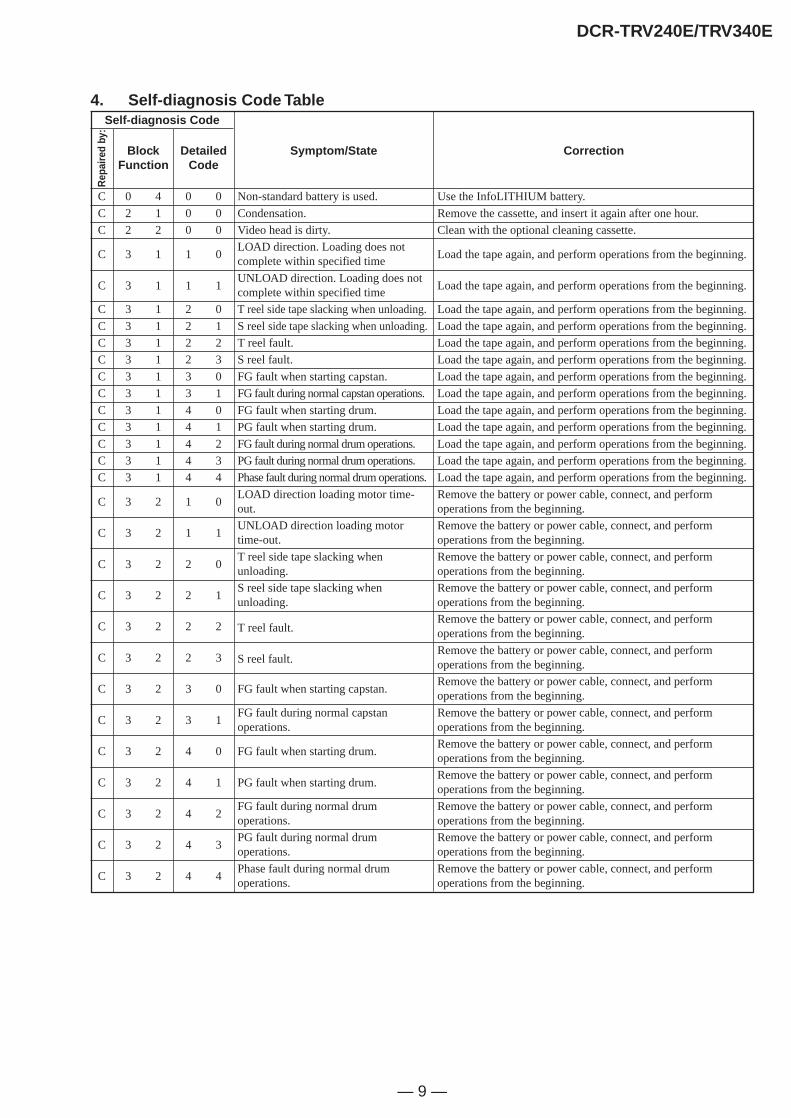
4. Self-diagnosis Code Table
C
C
C
C
C
C
C
C
C
C
C
C
C
C
C
C
C
C
C
C
C
C
C
C
C
C
C
C
C
BlockFunction
0 4
2 1
2 2
3 1
3 1
3 1
3 1
3 1
3 1
3 1
3 1
3 1
3 1
3 1
3 1
3 1
3 2
3 2
3 2
3 2
3 2
3 2
3 2
3 2
3 2
3 2
3 2
3 2
3 2
DetailedCode
0 0
0 0
0 0
1 0
1 1
2 0
2 1
2 2
2 3
3 0
3 1
4 0
4 1
4 2
4 3
4 4
1 0
1 1
2 0
2 1
2 2
2 3
3 0
3 1
4 0
4 1
4 2
4 3
4 4
Symptom/State
Non-standard battery is used.
Condensation.
Video head is dirty.
LOAD direction. Loading does notcomplete within specified time
UNLOAD direction. Loading does notcomplete within specified time
T reel side tape slacking when unloading.
S reel side tape slacking when unloading.
T reel fault.
S reel fault.
FG fault when starting capstan.
FG fault during normal capstan operations.
FG fault when starting drum.
PG fault when starting drum.
FG fault during normal drum operations.
PG fault during normal drum operations.
Phase fault during normal drum operations.
LOAD direction loading motor time-out.
UNLOAD direction loading motortime-out.
T reel side tape slacking whenunloading.
S reel side tape slacking whenunloading.
T reel fault.
S reel fault.
FG fault when starting capstan.
FG fault during normal capstanoperations.
FG fault when starting drum.
PG fault when starting drum.
FG fault during normal drumoperations.
PG fault during normal drumoperations.
Phase fault during normal drumoperations.
Self-diagnosis Code
Rep
aire
d by
:
Correction
Use the InfoLITHIUM battery.
Remove the cassette, and insert it again after one hour.
Clean with the optional cleaning cassette.
Load the tape again, and perform operations from the beginning.
Load the tape again, and perform operations from the beginning.
Load the tape again, and perform operations from the beginning.
Load the tape again, and perform operations from the beginning.
Load the tape again, and perform operations from the beginning.
Load the tape again, and perform operations from the beginning.
Load the tape again, and perform operations from the beginning.
Load the tape again, and perform operations from the beginning.
Load the tape again, and perform operations from the beginning.
Load the tape again, and perform operations from the beginning.
Load the tape again, and perform operations from the beginning.
Load the tape again, and perform operations from the beginning.
Load the tape again, and perform operations from the beginning.
Remove the battery or power cable, connect, and performoperations from the beginning.
Remove the battery or power cable, connect, and performoperations from the beginning.
Remove the battery or power cable, connect, and performoperations from the beginning.
Remove the battery or power cable, connect, and performoperations from the beginning.
Remove the battery or power cable, connect, and performoperations from the beginning.
Remove the battery or power cable, connect, and performoperations from the beginning.
Remove the battery or power cable, connect, and performoperations from the beginning.
Remove the battery or power cable, connect, and performoperations from the beginning.
Remove the battery or power cable, connect, and performoperations from the beginning.
Remove the battery or power cable, connect, and performoperations from the beginning.
Remove the battery or power cable, connect, and performoperations from the beginning.
Remove the battery or power cable, connect, and performoperations from the beginning.
Remove the battery or power cable, connect, and performoperations from the beginning.
— 10 —
DCR-TRV240E/TRV340E
E
E
E
E
BlockFunction
6 1
6 1
6 2
6 2
DetailedCode
0 0
1 0
0 0
0 1
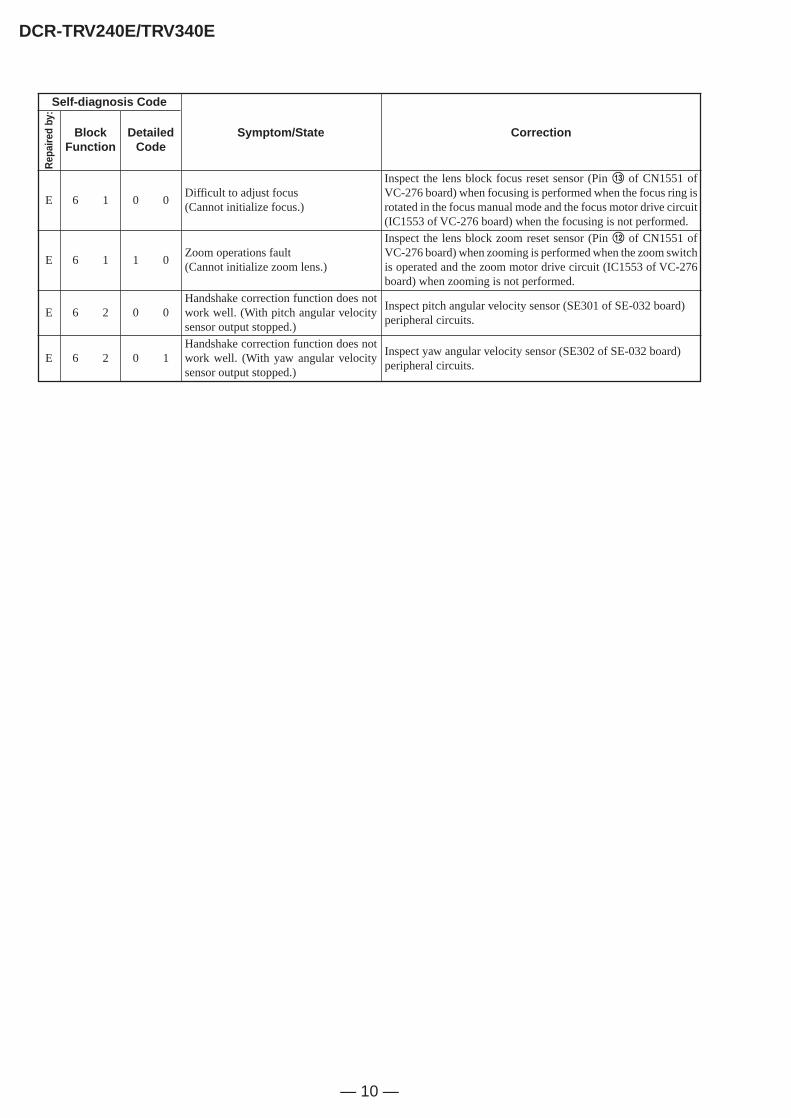
Symptom/State
Difficult to adjust focus(Cannot initialize focus.)
Zoom operations fault(Cannot initialize zoom lens.)
Handshake correction function does notwork well. (With pitch angular velocitysensor output stopped.)
Handshake correction function does notwork well. (With yaw angular velocitysensor output stopped.)
Self-diagnosis Code
Rep
aire
d by
:
Correction
Inspect the lens block focus reset sensor (Pin qd of CN1551 ofVC-276 board) when focusing is performed when the focus ring isrotated in the focus manual mode and the focus motor drive circuit(IC1553 of VC-276 board) when the focusing is not performed.
Inspect the lens block zoom reset sensor (Pin qs of CN1551 ofVC-276 board) when zooming is performed when the zoom switchis operated and the zoom motor drive circuit (IC1553 of VC-276board) when zooming is not performed.
Inspect pitch angular velocity sensor (SE301 of SE-032 board)peripheral circuits.
Inspect yaw angular velocity sensor (SE302 of SE-032 board)peripheral circuits.

1-1
SECTION 1GENERAL
DCR-TRV240E/TRV340E
This section is extracted frominstruction manual.DCR-TRV240E/TRV340E (3-072-651-11(1))
4
Recording moving or still images, and playing them back•Recording moving pictures on a tape (p. 28)•Recording still images on a tape (p. 51)•Playing back a tape (p. 43)•Recording still images on “Memory Stick”s (DCR-TRV340E only) (p. 167)•Recording moving pictures on “Memory Stick”s (DCR-TRV340E only) (p. 187)•Viewing still images recorded on “Memory Stick”s (DCR-TRV340E only) (p. 198)•Viewing moving pictures on “Memory Stick”s (DCR-TRV340E only) (p. 202)
Capturing images on your computer•Viewing images recorded on “Memory Stick”s using the USB cable (DCR-TRV340E only) (p. 204)•Viewing images recorded on a tape using the USB cable (p. 123)•Viewing images live on your computer from your camcorder using the USB cable (p. 132)•Capturing images from an analog video unit on your computer (p. 114)
Other usesFunctions for adjusting exposure in the recording mode•BACKLIGHT (p. 36)•NightShot/Super NightShot/Colour Slow Shutter (p. 37)•PROGRAM AE (p. 65)•Adjusting the exposure manually (p. 68)
Functions for giving images more impact•Digital zoom [MENU] (p. 31) The default setting is OFF. (To zoom greater than 25×, select the digital
zoom power in D ZOOM in the menu settings.)•Fader (p. 57)•Picture effects (p. 60)•Digital effects (p. 62)•Titles (p. 75, 78)•MEMORY MIX (DCR-TRV340E only) (p. 174)
Functions for giving a natural appearance to your recordings•Sports lesson (p. 65)•Landscape (p. 65)•Manual focus (p. 69)
Functions for use on recorded tapes•END SEARCH/EDITSEARCH/Rec Review (p. 41)•DATA CODE (p. 44)•Tape PB ZOOM (p. 86)•ZERO SET MEMORY (p. 88)•Digital program editing (on tapes) (p. 97)/(on “Memory Stick”s) (DCR-TRV340E only) (p. 193)
English
Main features
b
10
Qu
ick Start Gu
ide
English
Quick Start Guide
This chapter introduces you to the basic features of yourcamcorder. See the page in parentheses “( )” for moreinformation.
Inserting a cassette (p. 26)
Connecting the mains lead (p. 23)
Use the battery pack when using your camcorder outdoors (p. 18).
1 Slide OPEN/EJECT inthe direction of thearrow and open thelid.
2 Insert the cassette instraight as far aspossible into thecassette compartmentwith the windowfacing up.Push the centre of thecassette back to insertthe cassette.
3Close the cassettecompartment bypressing on thecassette compartment.After the cassettecompartment goesdown completely,close the lid until itclicks.
Open the DC INjack cover.
Connect the plug withits v mark facing up.
AC power adaptor (supplied)
11
Qu
ick Start Gu
ide
Recording a picture (p. 28)
2 Set the POWERswitch to CAMERAwhile pressing thesmall green button.
1Remove the lens cap.
When you purchase your camcorder, the clock setting is set to off. If you want to record the dateand time for a picture, set the clock setting before recording (p. 24).
Monitoring the playback picture on the LCDscreen (p. 43)
2Press m to rewind the tape.
3Press N to start playback.
NoteDo not pick up your camcorder byholding the viewfinder, the LCDpanel, or the battery pack.
1Set the POWERswitch to VCR whilepressing the smallgreen button.
CAMERA
MEMORY
VCROFF(CHG
)
POWER
REW
PLAY
CAMERA
MEMORY
VCROFF(CHG
)POWER
3Open the LCD panelwhile pressing OPEN.The picture appearson the LCD screen.
4Press START/STOP.Your camcorderstarts recording. Tostop recording, pressSTART/STOP buttonagain.
ViewfinderWhen the LCD panel is closed, use the viewfinder with your eyeagainst the eyecup.The picture in the viewfinder is black and white.
1-2
DCR-TRV240E/TRV340E
14
— Getting Started —
Using this manual
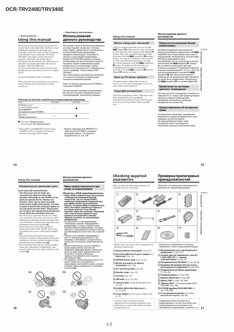
The instructions in this manual are for the twomodels listed in the table below. Before you startreading this manual and operating yourcamcorder, check the model number by lookingat the bottom of your camcorder. The DCR-TRV340E is the model used for illustrationpurposes. Otherwise, the model name isindicated in the illustrations. Any differences inoperation are clearly indicated in the text, forexample, “DCR-TRV340E only.”As you read through this manual, buttons andsettings on your camcorder are shown in capitalletters.
e.g. Set the POWER switch to CAMERA.
When you carry out an operation, you can hear abeep to indicate that the operation is beingcarried out.
* The models with MEMORY marked on thePOWER switch is provided with memoryfunctions. See page 158 for details.
— Подготовка к эксплуатации —
Использованиеданного руководства
Инструкции в данном руководстве приведеныдля двух моделей, указанных в таблицениже. Перед чтением данного руководства иэксплуатацией Вашей видеокамерыпроверьте номер модели, посмотрев нанижнюю сторону Вашей видеокамеры.Модель DCR-TRV340E является моделью,используемой для иллюстративных целей. Впротивном случае наименование моделиизображается на иллюстрации. Любыеотличия в эксплуатации ясно отображаются втексте, например, “только модель DCR-TRV340E”.При чтении данного руководства учитывайте,что кнопки и установки на видеокамерепоказаны заглавными буквами.
Напр. Установите переключатель POWER вположение CAMERA.
При выполнении операции на видеокамереВы сможете услышать зуммерный сигнал,подтверждающий выполнение операции.
* Модели, имеющие знак MEMORY напереключателе POWER, оснащеныфункциями памяти. Что касаетсяподробностей, см. стр. 158.
Differences by camcorder model/Отличия между моделями видеокамерDCR- TRV240E TRV340E
MEMORY mark*(on the POWER switch)/ — zЗнак MEMORY*(на переключателе POWER)
Self-timer/ — zТаймер самозапуска
z Provided/Предусмотрено— Not provided/Не предусмотрено
15
Gettin
g Started
По
дго
тов
ка к
эксп
луатац
ии
Using this manual
Before using your camcorder
With your digital camcorder, you can use Hi8/Digital8 video cassettes. Your camcorder
records and plays back pictures in the Digital8 system. Also, your camcorder plays back tapesrecorded in the Hi8 /standard 8 (analog)system. You, however, cannot use the functionsin “Advanced Playback Operations” on page82 to 92 for playback in the Hi8 /standard 8
system. To enable smooth transition, werecommend that you do not mix picturesrecorded in the Hi8 /standard 8 with theDigital8 system on a tape.
Note on TV colour systems
TV colour systems differ from country tocountry. To view your recordings on a TV, youneed a PAL system-based TV.
Copyright precautions
Television programmes, films, video tapes, andother materials may be copyrighted.Unauthorized recording of such materials maybe contrary to the provision of the copyrightlaws.
Использование данногоруководства
Перед использованием Вашейвидеокамеры
Для Вашей цифровой видеокамеры Выможете использовать видеокассеты Hi8 /Digital8 . Ваша видеокамера записывает ивоспроизводит изображения в системе Digital8 . Ваша видеокамера такжевоспроизводит ленты, записанные в системе(аналоговой) Hi8 /standard 8 . Однако,Вы не можете использовать функции,описанные в разделе “Усовершенствованныеоперации воспроизведения” на стр. с 82 по 92для воспроизведения в системе Hi8 /standard 8 . Для обеспечения плавногоперехода мы не рекомендуем Вам смешиватьна одной ленте изображения, записанные вHi8 /standard 8 и в системе Digital 8 .
Примечание по системамцветного телевидения
Системы цветного телевидения отличаются взависимости от страны. Для просмотра Вашихзаписей на экране телевизора Вамнеобходимо использовать телевизор,основанный на системе PAL.
Предостережение об авторскомправе
Телевизионные программы, кинофильмы,видеоленты и другие материалы могут бытьзащищены авторским правом.Не лицензированная запись такихматериалов может противоречитьположениям законов об авторском праве.
16
Using this manual
Precautions on camcorder care
Lens and LCD screen/finder• The LCD screen and the finder are
manufactured using extremely high-precision technology so over 99.99% of thepixels are operational for effective use.However, there may be some tiny blackpoints and/or bright points (white, red, blueor green in colour) that constantly appear onthe LCD screen and the finder. These pointsare normal in the manufacturing process anddo not affect the recording in any way.
•Do not let your camcorder become wet. Keepyour camcorder away from rain and sea water.Letting your camcorder become wet may causeyour camcorder to malfunction. Sometimes thismalfunction cannot be repaired [a].
•Never leave your camcorder exposed totemperatures above 60°C (140°F), such as in acar parked in the sun or under direct sunlight[b].
•Be careful when placing the camera near awindow or outdoors. Exposing the LCD screen,the finder or the lens to direct sunlight for longperiods may cause malfunctions [c].
•Do not directly shoot the sun. Doing so mightcause your camcorder to malfunction. Takepictures of the sun in low light conditions suchas dusk [d].
[a] [b]
[c] [d]
Использование данногоруководства
Меры предосторожности приуходе за видеокамерой
Объектив и ЖКД экран/видоискатель• Экран ЖКД и видоискатель изготовлены
с помощью высокопрецизионнойтехнологии, так что свыше 99,99%элементов изображения предназначеныдля эффективного использования.Однако, на экране ЖКД и в видоискателемогут постоянно появляться черные и/или яркие цветные точки (белые,красные, синие или зеленые). Появлениеэтих точек вполне нормально дляпроцесса изготовления и никоимобразом не влияет на записываемоеизображение.
•Не допускайте, чтобы видеокамерастановилась влажной. Предохраняйтевидеокамеру от дождя и морской воды.Если Вы намочите видеокамеру, это можетпривести к неисправности аппарата. Иногдаэта неисправность может быть не устранена[a].
•Никогда не оставляйте видеокамеру вместе с температурой выше 60°С, как,например, в автомобиле, оставленном насолнце или под прямым солнечным светом[b].
•Будьте внимательны, когда оставляетевидеокамеру вблизи окна или внепомещения. Действие прямого солнечногосвета на экран ЖКД, видоискатель илиобъектив в течение длительныхпромежутков времени может вызватьнеисправности [c].
•Не снимайте солнце непосредственно. Этоможет привести к неисправностивидеокамеры. Выполняйте съемку солнца вусловиях низкой освещенности, например,на закате [d].
17
Gettin
g Started
По
дго
тов
ка к
эксп
луатац
ии
Checking suppliedaccessories
Make sure that the following accessories aresupplied with your camcorder.
* Differs from area to area. This is supplied withEuropean models only.
1Wireless Remote Commander (1) (p. 277)
2AC-L10A/L10B/L10C AC power adaptor (1),Mains lead (1) (p. 19)
3NP-FM30 battery pack (1) (p. 18, 19)
4 R6 (size AA) battery for RemoteCommander (2) (p. 278)
5A/V connecting cable (1) (p. 49)
6 Shoulder strap (1) (p. 270)
7 Lens cap (1) (p. 28)
8USB cable (1) (p. 125, 205)
9 “Memory Stick” (1) (DCR-TRV340E only)(p. 158)
0 CD-ROM (SPVD-008 USB Driver) (1)(p. 125, 205)
qa 21-pin adaptor (1) (European models only)(p. 50)
Contents of the recording cannot becompensated if recording or playback is notmade due to a malfunction of the camcorder,storage media, etc.
1 2 3
4 5 6 7
8 9 0 qa *
Проверка прилагаемыхпринадлежностей
Убедитесь, что следующие принадлежностиприлагаются к Вашей видеокамере.
* Отличается в зависимости от региона.Прилагается только к европейской модели.
1Беспроводный пульт дистанционногоуправления (1) (стр. 277)
2Сетевой адаптер переменного тока AC-L10A/L10B/L10C (1), проводэлектропитания (1) (стр. 19)
3Батарейный блок NP-FM30 (1) (стр. 18, 19)
4Батарейка R6 (размера АА) для пультадистанционного управления (2) (стр. 278)
5Соединительный кабель аудио/видео(1) (стр. 49)
6Плечевой ремень (1) (стр. 270)
7Крышка объектива (1) (стр. 28)
8Кабель USB (1) (стр. 125, 205)
9 “Memory Stick” (1) (только модель DCR-TRV340E) (стр. 158)
0CD-ROM (драйвер SPVD-008 USB) (1)(стр. 125, 205)
qa 21-штырьковый адаптер (1) (толькоевропейские модели) (стр. 50)
Содержание записи не может бытькомпенсировано в случае, если запись иливоспроизведение не выполнены из-занеисправности видеокамеры, носителя и т.п.
1-3
DCR-TRV240E/TRV340E
18
Step 1 Preparing thepower supply
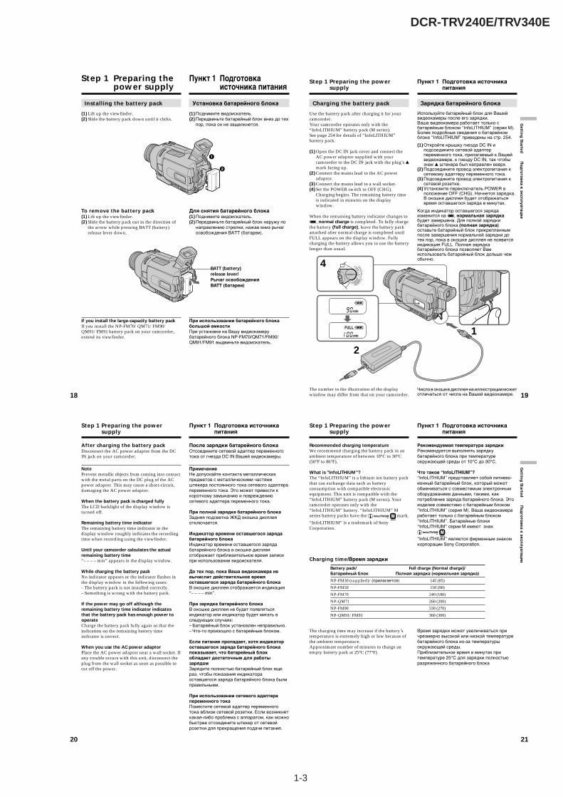
Installing the battery pack
(1) Lift up the viewfinder.(2) Slide the battery pack down until it clicks.
To remove the battery pack(1) Lift up the viewfinder.(2) Slide the battery pack out in the direction of
the arrow while pressing BATT (battery)release lever down.
If you install the large-capacity battery packIf you install the NP-FM70/QM71/FM90/QM91/FM91 battery pack on your camcorder,extend its viewfinder.
Установка батарейного блока
(1) Поднимите видоискатель.(2) Передвиньте батарейный блок вниз до тех
пор, пока он не защелкнется.
Для снятия батарейного блока(1) Поднимите видоискатель.(2) Передвиньте батарейный блок наружу по
направлению стрелки, нажав вниз рычагосвобождения BATT (батареи).
При использовании батарейного блокабольшой емкостиПри установке на Вашу видеокамерубатарейного блока NP-FM70/QM71/FM90/QM91/FM91 выдвиньте видоискатель.
Пункт 1 Подготовкаисточника питания
BATT (battery)release lever/Рычаг освобожденияBATT (батареи)
1
2
19
Gettin
g Started
По
дго
тов
ка
к э
кс
пл
уа
тац
ии
Charging the battery pack
Use the battery pack after charging it for yourcamcorder.Your camcorder operates only with the“InfoLITHIUM” battery pack (M series).See page 254 for details of “InfoLITHIUM”battery pack.
(1) Open the DC IN jack cover and connect theAC power adaptor supplied with yourcamcorder to the DC IN jack with the plug’s vmark facing up.
(2) Connect the mains lead to the AC poweradaptor.
(3) Connect the mains lead to a wall socket.(4) Set the POWER switch to OFF (CHG).
Charging begins. The remaining battery timeis indicated in minutes on the displaywindow.
When the remaining battery indicator changes tou, normal charge is completed. To fully chargethe battery (full charge), leave the battery packattached after normal charge is completed untilFULL appears on the display window. Fullycharging the battery allows you to use the batterylonger than usual.
The number in the illustration of the displaywindow may differ from that on your camcorder.
Step 1 Preparing the powersupply
4
1
2
CAMERA
MEMORY
VCROFF(CHG
)POWER
Зарядка батарейного блока
Используйте батарейный блок для Вашейвидеокамеры после его зарядки.Ваша видеокамера работает только сбатарейным блоком “InfoLITHIUM” (серии M).Более подробные сведения о батарейномблоке “InfoLITHIUM” приведены на стр. 254.
(1)Откройте крышку гнезда DC IN иподсоедините сетевой адаптерпеременного тока, прилагаемый к Вашейвидеокамере, к гнезду DC IN, так чтобызнак v штекера был направлен вверх.
(2)Подсоедините провод электропитания ксетевому адаптеру переменного тока.
(3)Подсоедините провод электропитания ксетевой розетке.
(4)Установите переключатель POWER вположение OFF (CHG). Начнется зарядка.В окошке дисплея будет отображатьсявремя оставшегося заряда в минутах.
Когда индикатор оставшегося зарядаизменится на u, нормальная зарядкабудет завершена. Для полной зарядкибатарейного блока (полная зарядка)оставьте батарейный блок прикрепленнымпосле завершения нормальной зарядки дотех пор, пока в окошке дисплея не появитсяиндикация FULL. Полная зарядкабатарейного блока позволяет Вамиспользовать батарейный блок дольше чемобычно.
Число в окошке дисплея на иллюстрации можетотличаться от числа на Вашей видеокамере.
Пункт 1 Подготовка источникапитания
20
After charging the battery packDisconnect the AC power adaptor from the DCIN jack on your camcorder.
NotePrevent metallic objects from coming into contactwith the metal parts on the DC plug of the ACpower adaptor. This may cause a short-circuit,damaging the AC power adaptor.
When the battery pack is charged fullyThe LCD backlight of the display window isturned off.
Remaining battery time indicatorThe remaining battery time indicator in thedisplay window roughly indicates the recordingtime when recording using the viewfinder.
Until your camcorder calculates the actualremaining battery time“– – – – min” appears in the display window.
While charging the battery packNo indicator appears or the indicator flashes inthe display window in the following cases:– The battery pack is not installed correctly.– Something is wrong with the battery pack.
If the power may go off although theremaining battery time indicator indicatesthat the battery pack has enough power tooperateCharge the battery pack fully again so that theindication on the remaining battery timeindicator is correct.
When you use the AC power adaptorPlace the AC power adaptor near a wall socket. Ifany trouble occurs with this unit, disconnect theplug from the wall socket as soon as possible tocut off the power.
Step 1 Preparing the powersupply
После зарядки батарейного блокаОтсоедините сетевой адаптер переменноготока от гнезда DC IN Вашей видеокамеры.
ПримечаниеНе допускайте контакта металлическихпредметов с металлическими частямиштекера постоянного тока сетевого адаптерапеременного тока. Это может привести ккороткому замыканию и повреждениюсетевого адаптера переменного тока.
При полной зарядке батарейного блокаЗадняя подсветка ЖКД окошка дисплеяотключается.
Индикатор времени оставшегося зарядабатарейного блокаИндикатор времени оставшегося зарядабатарейного блока в окошке дисплеяотображает приблизительное время записипри использовании видоискателя.
До тех пор, пока Ваша видеокамера невычислит действительное времяоставшегося заряда батарейного блокаВ окошке дисплея отображается индикация“– – – – min”.
При зарядке батарейного блокаВ окошке дисплея не будет появлятьсяиндикатор или индикатор будет мигать вследующих случаях:– Батарейный блок установлен неправильно.– Что-то произошло с батарейным блоком.
Если питание пропадает, хотя индикатороставшегося заряда батарейного блокапоказывает, что батарейный блокобладает достаточным для работызарядомЗарядите полностью батарейный блок ещераз, чтобы показания индикатораоставшегося заряда батарейного блока былиправильными.
При использовании сетевого адаптерапеременного токаПоместите сетевой адаптер переменноготока вблизи сетевой розетки. Если возникнеткакая-либо проблема с аппаратом, как можнобыстрее отсоедините штекер от сетевойрозетки для прекращения подачи питания.
Пункт 1 Подготовка источникапитания
21
Gettin
g Started
По
дго
тов
ка
к э
кс
пл
уа
тац
ии
Step 1 Preparing the powersupply
Recommended charging temperatureWe recommend charging the battery pack in anambient temperature of between 10°C to 30°C(50°F to 86°F).
What is ”InfoLITHIUM”?The “InfoLITHIUM” is a lithium ion battery packthat can exchange data such as batteryconsumption with compatible electronicequipment. This unit is compatible with the“InfoLITHIUM” battery pack (M series). Yourcamcorder operates only with the“InfoLITHIUM” battery. “InfoLITHIUM” Mseries battery packs have the
SERIESTM
mark.
“InfoLITHIUM” is a trademark of SonyCorporation.
The charging time may increase if the battery’stemperature is extremely high or low because ofthe ambient temperature.Approximate number of minutes to charge anempty battery pack at 25°C (77°F)
Рекомендуемая температура зарядкиРекомендуется выполнять зарядкубатарейного блока при температуреокружающей среды от 10°C до 30°C.
Что такое “InfoLITHIUM”?“InfoLITHIUM” представляет собой литиево-ионный батарейный блок, который можетобмениваться с совместимым электроннымоборудованием данными, такими, какпотребление заряда батарейного блока. Этоизделие совместимо с батарейным блоком“InfoLITHIUM” (серия M). Ваша видеокамераработает только с батарейным блоком“InfoLITHIUM”. Батарейные блоки“InfoLITHIUM” серии M имеют знак
SERIESTM
.
“InfoLITHIUM” является фирменным знакомкорпорации Sony Corporation.
Время зарядки может увеличиваться причрезмерно высокой или низкой температуребатарейного блока из-за температурыокружающей среды.Приблизительное время в минутах притемпературе 25°C для зарядки полностьюразряженного батарейного блока
Пункт 1 Подготовка источникапитания
Charging time/Время зарядки
Battery pack/ Full charge (Normal charge)/Батарейный блок Полная зарядка (нормальная зарядка)
NP-FM30 (supplied)/(прилагается) 145 (85)
NP-FM50 150 (90)
NP-FM70 240 (180)
NP-QM71 260 (200)
NP-FM90 330 (270)
NP-QM91/FM91 360 (300)
1-4
DCR-TRV240E/TRV340E
22
Step 1 Preparing the powersupply
Approximate number of minutes when you use afully charged battery
* Approximate continuous recording time at25°C (77°F). The battery life will be shorter ifyou use your camcorder in a coldenvironment.
** Approximate number of minutes whenrecording while you repeat recording start/stop, zooming and turning the power on/off.The actual battery life may be shorter.
Approximate number of minutes when you use afully charged battery
Approximate continuous playing time at 25°C(77°F). The battery life will be shorter if you useyour camcorder in a cold environment.
NoteThe table shows the playing time for tapesrecorded in the Digital8 system. The playingtime of tapes recorded in the Hi8/standard 8system is reduced by about 20%.
Пункт 1 Подготовка источникапитания
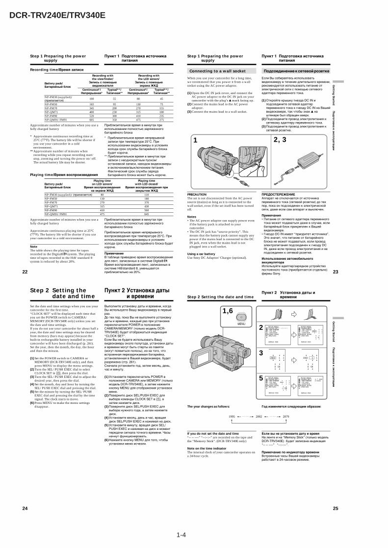
Recording time/Время записи
Recording with Recording withthe viewfinder/ the LCD screen/
Battery pack/ Запись с помощью Запись с помощью
Батарейный блок видоискателя экрана ЖКДContinuous*/ Typical**/ Continuous*/ Typical**/
Непрерывная* Типичная** Непрерывная* Типичная**NP-FM30 (supplied)/ 100 55 80 45(прилагается)NP-FM50 165 95 130 75NP-FM70 345 200 270 155NP-QM71 400 230 315 180NP-FM90 520 300 410 235NP-QM91/FM91 605 350 475 275
Приблизительное время в минутах прииспользовании полностью заряженногобатарейного блока
* Приблизительное время непрерывнойзаписи при температуре 25°С. Прииспользовании видеокамеры в условияххолода срок службы батарейного блокабудет короче.
** Приблизительное время в минутах призаписи с неоднократным пуском/остановкой записи, наездом видеокамерыи включением/выключением питания.Фактический срок службы зарядабатарейного блока может быть короче.
Приблизительное время в минутах прииспользовании полностью заряженногобатарейного блока
Приблизительное время непрерывноговоспроизведения при температуре 25°С. Прииспользовании видеокамеры в условияххолода срок службы батарейного блока будеткороче.
ПримечаниеВ таблице приведено время воспроизведениядля лент, записанных в системе Digital8 .Время воспроизведения лент, записанных всистеме Hi8/standard 8, уменьшаетсяприблизительно на 20%.
Playing time/Время воспроизведения
Playing time Playing timeBattery pack/ on LCD screen/ with LCD closed/Батарейный блок Время воспроизведения Время воспроизведения при
на экране ЖКД закрытом ЖКДNP-FM30 (supplied)/(прилагается) 80 110NP-FM50 130 180NP-FM70 270 370NP-QM71 315 430NP-FM90 410 560NP-QM91/FM91 475 645
23
Gettin
g Started
По
дго
тов
ка к
эксп
луатац
ии
Connecting to a wall socket
When you use your camcorder for a long time,we recommend that you power it from a wallsocket using the AC power adaptor.
(1) Open the DC IN jack cover, and connect theAC power adaptor to the DC IN jack on yourcamcorder with the plug’s v mark facing up.
(2) Connect the mains lead to the AC poweradaptor.
(3) Connect the mains lead to a wall socket.
PRECAUTIONThe set is not disconnected from the AC powersource (mains) as long as it is connected to thewall socket, even if the set itself has been turnedoff.
Notes•The AC power adaptor can supply power even
if the battery pack is attached to yourcamcorder.
•The DC IN jack has “source priority”. Thismeans that the battery pack cannot supply anypower if the mains lead is connected to the DCIN jack, even when the mains lead is notplugged into a wall socket.
Using a car batteryUse Sony DC Adaptor/Charger (optional).
Step 1 Preparing the powersupply
Пункт 1 Подготовка источникапитания
Подсоединение к сетевой розетке
Если Вы собираетесь использоватьвидеокамеру в течение длительного времени,рекомендуется использовать питание отэлектрической сети с помощью сетевогоадаптера переменного тока.
(1) Откройте крышку гнезда DC IN иподсоедините сетевой адаптерпеременного тока к гнезду DC IN на Вашейвидеокамере, так чтобы знак v наштекере был обращен вверх.
(2) Подсоедините провод электропитания ксетевому адаптеру переменного тока.
(3) Подсоедините провод электропитания ксетевой розетке.
ПРЕДОСТЕРЕЖЕНИЕАппарат не отключается от источникапеременного тока (сетевой розетки) до техпор, пока он подсоединен к электрическойсети, даже если сам аппарат и выключен.
Примечания•Питание от сетевого адаптера переменного
тока может подаваться даже в случае, еслибатарейный блок прикреплен к Вашейвидеокамере.
•Гнездо DC IN имеет “приоритет источника”.Это значит, что питание от батарейногоблока не может подаваться, если проводэлектропитания подсоединен к гнезду DCIN, даже если провод электропитания и неподсоединен к сетевой розетке.
Использование автомобильногоаккумулятораИспользуйте адаптер/зарядное устройствопостоянного тока (приобретается отдельно)фирмы Sony.
2, 31
24
Step 2 Setting thedate and time
Set the date and time settings when you use yourcamcorder for the first time.“CLOCK SET” will be displayed each time thatyou set the POWER switch to CAMERA/MEMORY (DCR-TRV340E only) unless you setthe date and time settings.If you do not use your camcorder for about half ayear, the date and time settings may be clearedfrom memory (bars may appear) because thebuilt-in rechargeable battery installed in yourcamcorder will have been discharged (p. 261).Set the year, then the month, the day, the hourand then the minute.
(1) Set the POWER switch to CAMERA orMEMORY (DCR-TRV340E only), and thenpress MENU to display the menu settings.
(2) Turn the SEL/PUSH EXEC dial to selectCLOCK SET in , then press the dial.
(3) Turn the SEL/PUSH EXEC dial to adjust thedesired year, then press the dial.
(4) Set the month, day and hour by turning theSEL/PUSH EXEC dial and pressing the dial.
(5) Set the minute by turning the SEL/PUSHEXEC dial and pressing the dial by the timesignal. The clock starts to move.
(6) Press MENU to make the menu settingsdisappear.
Пункт 2 Установка датыи времени
Выполните установку даты и времени, когдаВы используете Вашу видеокамеру в первыйраз.До тех пор, пока Вы не выполните установкудаты и времени, каждый раз при установкепереключателя POWER в положениеCAMERA/MEMORY (только модель DCR-TRV340E) будет отображаться индикация“CLOCK SET”.Если Вы не будете использовать Вашувидеокамеру около полугода, установки датыи времени могут быть стерты из памяти(могут появиться полосы), из-за того, чтовстроенная перезаряжаемая батарейка,установленная в Вашей видеокамере, будетразряжена (стр. 261).Сначала установите год, затем месяц, день,час и минуту.
(1) Установите переключатель POWER вположение CAMERA или MEMORY (толькомодель DCR-TRV340E), а затем нажмитекнопку MENU для отображения установокменю.
(2) Поверните диск SEL/PUSH EXEC длявыбора команды CLOCK SET в , азатем нажмите диск.
(3) Поверните диск SEL/PUSH EXEC длявыбора нужного года, а затем нажмитедиск.
(4) Установите месяц, день и час, вращаядиск SEL/PUSH EXEC и нажимая на диск.
(5) Установите минуту, вращая диск SEL/PUSH EXEC и нажимая на диск в моментпередачи сигнала точного времени. Часыначнут функционировать.
(6) Нажмите кнопку MENU для того, чтобыустановки меню исчезли.
25
Gettin
g Started
По
дго
тов
ка к
эксп
луатац
ии
Step 2 Setting the date and time
The year changes as follows:
If you do not set the date and time“-- -- ----” “--:--:--” are recorded on the tape andthe “Memory Stick”. (DCR-TRV340E only)
Note on the time indicatorThe internal clock of your camcorder operates ona 24-hour cycle.
1,6
MENU
2
3
5
SETUP MENU CLOCK SET USB STREAM LTR SIZE LANGUAGE DEMO MODE RETURN
– –:– –:– –
[MENU] : END
SETUP MENU CLOCK SET USB STREAM LTR SIZE LANGUAGE DEMO MODE RETURN
2002 1 1
0 00
[MENU] : END
2002 1 1
0 00
SETUP MENU CLOCK SET USB STREAM LTR SIZE LANGUAGE DEMO MODE RETURN
2002 7 4
17 30
[MENU] : END
SETUP MENU CLOCK SET USB STREAM LTR SIZE LANGUAGE DEMO MODE RETURN
4 7 200217:30:00
[MENU] : END
2002 1 1
0 00
Пункт 2 Установка даты ивремени
Год изменяется следующим образом:
Если вы не установите дату и времяНа ленте и на “Memory Stick” (только модельDCR-TRV340E) будет записана индикация“-- -- ----” “--:--:--”.
Примечание по индикатору времениВстроенные часы Вашей видеокамерыработают в 24-часовом режиме.
1995 T · · · · t 2002 T · · · · t 2079
1-5
DCR-TRV240E/TRV340E
26
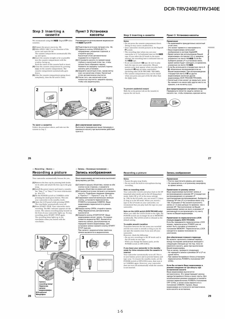
We recommend using Hi8 /Digital8 videocassettes.
(1) Prepare the power source (p. 18).(2) Slide OPEN/EJECT in the direction of the
arrow and open the lid.The cassette compartment automatically liftsup and opens.
(3) Insert the cassette straight as far as possibleinto the cassette compartment with thewindow facing up.Push the centre of the cassette back to insert.
(4) Close the cassette compartment by pressing on the cassette compartment. The
cassette compartment automatically goesdown.
(5) After the cassette compartment going downcompletely, close the lid until it clicks.
To eject a cassetteFollow the procedure above, and take out thecassette in step 3.
Step 3 Inserting acassette
2 3 4,5
4
5
Рекомендуется использование видеокассетHi8 /Digital8 .
(1) Подготовьте источник питания (стр. 18).(2) Сдвиньте кнопку OPEN/EJECT в
направлении, указанном стрелкой, иоткройте крышку.Кассетный отсек автоматическиподнимется и откроется.
(3) Установите кассету по прямой линииглубоко в кассетный отсек так, чтобыокошко было обращено наружу.Нажмите на середину тыльной стороныкассеты для установки.
(4) Закройте кассетный отсек, нажав метку на кассетном отсеке. Кассетный
отсек автоматически опустится.(5) После того, как кассетный отсек
полностью опустится, закройте крышку,чтобы она защелкнулась.
Для извлечения кассетыВыполните приведенную выше процедуру иизвлеките кассету при выполнении действийпункта 3.
Пункт 3 Установкакассеты
27
Gettin
g Started
По
дго
тов
ка
к э
кс
пл
уа
тац
ии
Step 3 Inserting a cassette
Notes•Do not press the cassette compartment down.
Doing so may cause a malfunction.•Your camcorder records pictures in the Digital8
system.•The recording time when you use your
camcorder is 2/3 of indicated time on Hi8 tape. If you select the LP mode in the menusettings, the recording time is indicated time onHi8 tape.
•If you use standard 8 tape, be sure to playback the tape on your camcorder. Mosaicpattern noise may appear when you play backstandard 8 tape on other camcorders(including other DCR-TRV240E/TRV340E).
•The cassette compartment may not be closedwhen you press any part of the lid other thanthe mark.
To prevent accidental erasureSlide the write-protect tab on the cassette toexpose the red mark.
Пункт 3 Установка кассеты
Примечания•Не вдавливайте принудительно кассетный
отсек вниз.Это может привести к неисправности.
•Ваша видеокамера записываетизображения в системе Digital8 .
•Время записи при использовании Вашейвидеокамеры составляет 2/3 от времени,указанного на ленте Hi8 . Если Вывыберете режим LP в установках меню,время записи будет совпадать со временем,указанным на ленте Hi8 .
•Если Вы используете стандартную ленту 8, обязательно воспроизводите ее на
Вашей видеокамере. При воспроизведениистандартной ленты 8 на другихвидеокамерах (включая другиевидеокамеры DCR-TRV240E/TRV340E).
•Кассетный отсек может не закрыться, еслиВы нажмете на какое-либо другое место накрышке, а не на метку .
Для предотвращения случайного стиранияПередвиньте лепесток защиты записи накассете так, чтобы появилась красная метка.
28
Your camcorder automatically focuses for you.
(1) Remove the lens cap by pressing both knobson its sides and attach the lens cap to the gripstrap.
(2) Install the power source and insert a cassette.See “Step 1” to “Step 3” for more information(p. 18 to 27).
(3) Set the POWER switch to CAMERA whilepressing the small green button. This setsyour camcorder to the standby mode.
(4) Open the LCD panel while pressing OPEN.The viewfinder automatically turns off.
(5) Press START/STOP. Your camcorder startsrecording. The REC indicator appears on thescreen. The camera recording lamp located onthe front of your camcorder lights up. To stoprecording, press START/STOP again.The recording lamp lights up in theviewfinder when you record with theviewfinder.
— Recording – Basics —
Recording a picture
5
3
4
1
2
50min REC 0:00:01SP
CAMERA
MEMORY
VCROFF(CHG
)POWER
Camerarecording lamp/Лампочказаписивидеокамеры
Microphone/Микрофон
Ваша видеокамера автоматически выполняетфокусировку для Вас.
(1) Снимите крышку объектива, нажав на обекнопки на ее сторонах, и закрепитекрышку объектива на ремне для захвата.
(2)Установите источник питания и установитекассету. Подробные сведения приведеныв “Пункте 1” – “Пункте 3” (стр. 18 – 27).
(3) Удерживая нажатой маленькую зеленуюкнопку, установите переключательPOWER в положение CAMERA. Вашавидеокамера переключится в режиможидания.
(4) Нажав кнопку OPEN, откройте панельЖКД. Видоискатель автоматическивыключится.
(5) Нажмите кнопку START/STOP. Вашавидеокамера начнет запись. На экранепоявится индикатор REC. Высветитсялампочка записи, расположенная напередней панели видеокамеры. Дляостановки записи нажмите кнопку START/STOP еще раз.При записи с видоискателем лампочказаписи высветится в видоискателе.
— Запись – Основные положения —
Запись изображения
29
Reco
rdin
g – B
asics За
пи
сь
– Ос
но
вн
ые
по
ло
же
ни
я
Recording a picture
Notes•Fasten the grip strap firmly.•Do not touch the built-in microphone during
recording.
Note on recording modeYour camcorder records and plays back in the SP(standard play) mode and in the LP (long play)mode. Select SP or LP in the menu settings(p. 136). In the LP mode, you can record 1.5 timesas long as in the SP mode. When you record atape in the LP mode on your camcorder, werecommend that you play back the tape on yourcamcorder.
Note on the LOCK switch (DCR-TRV340E only)When you slide the LOCK switch to the right, thePOWER switch can no longer be set to MEMORYaccidentally. The LOCK switch is released as thedefault setting.
To enable smooth transitionTransition between the last scene you recordedand the next scene is smooth as long as you donot eject the cassette even if you turn off yourcamcorder.However, check the following:– Do not mix recordings in the SP mode and in
the LP mode on one tape.– When you change the battery pack, set the
POWER switch to OFF (CHG).
If you leave your camcorder in the standbymode for three minutes while the cassette isinsertedYour camcorder automatically turns off. This isto save battery power and to prevent battery andtape wear. To resume the standby mode, set thePOWER switch to OFF (CHG) once, then turn itto CAMERA again. However, your camcorderdoes not turn off automatically while the cassetteis not inserted.
Запись изображения
Примечания•Плотно пристегните ремень для захвата.•Не прикасайтесь к встроенному микрофону
во время записи.
Примечание по режиму записиВаша видеокамера выполняет запись ивоспроизведение в режиме SP (стандартноевоспроизведение) и в режиме LP(долгоиграющее воспроизведение). Выберитекоманду SP или LP в установках меню (стр.136). В режиме LP Вы можете выполнятьзапись в 1,5 раза дольше по времени, чем врежиме SP. При выполнении на Вашейвидеокамере записи на ленту в режиме LPрекомендуется воспроизводить эту лентутакже на Вашей видеокамере.
Примечание по переключателю LOCK(только модель DCR-TRV340E)Если Вы передвинете переключатель LOCKвправо, переключатель POWER уже неможет быть случайно установлен вположение MEMORY. Переключатель LOCKнаходится в правом положении поумолчанию.
Для обеспечения плавного переходаВы можете выполнять плавный переходмежду последним записанным эпизодом иследующим эпизодом до тех пор, пока неизвлечете кассету, даже при выключенииВашей видеокамеры.Тем не менее, проверьте следующее:– Не чередуйте записи в режимах SP и LP на
одной ленте.– При замене батарейного блока установите
переключатель POWER в положение OFF(CHG).
Если Вы оставите Вашу видеокамеру врежиме ожидания на три минуты привставленной кассетеВаша видеокамера выключитсяавтоматически. Это предотвращает расходзаряда батарейного блока и износ ленты. Длявозобновления режима ожидания установитесначала переключатель POWER в положениеOFF (CHG), а затем снова верните его вположение CAMERA. Однако, Вашавидеокамера не отключится автоматически,если кассета не вставлена.

1-6
DCR-TRV240E/TRV340E
30
When you record in the SP and LP modes onone tape or you record some scenes in the LPmode•The transition between scenes may not be
smooth.•The playback picture may be distorted or the
time code may not be written properly betweenscenes.
Recording dataThe recording data (date/time or various settingswhen recorded) are not displayed whilerecording. However, they are recordedautomatically onto the tape. To display therecording data, press DATA CODE on theRemote Commander during playback.
After recording
(1) Set the POWER switch to OFF (CHG).(2) Close the LCD panel.(3) Eject the cassette.(4) Remove the battery pack.
Adjusting the LCD screen
The LCD panel can be opened up to 90 degrees.The LCD panel moves about 90 degrees to theviewfinder side and about 180 degrees to the lensside.
When closing the LCD panel, set it verticallyuntil it clicks, and swing it into the camcorderbody.
Recording a picture
Если Вы записываете в режимах SP и LPна одной и той же кассете, или Вы записы-ваете некоторые эпизоды в режиме LP•Переход между эпизодами может не быть
плавным.•При воспроизведении изображение может
быть искажено или код времени может незаписаться правильно между эпизодами.
Данные записиДанные записи (дата/время или различныеустановки при записи) не отображаются вовремя записи. Тем не менее, ониавтоматически записываются на ленту.Чтобы отобразить дату и время записи,нажмите кнопку DATA CODE во времявоспроизведения.
После записи
(1) Установите переключатель POWER вположение OFF (CHG).
(2) Закройте панель ЖКД.(3) Извлеките кассету.(4) Удалите батарейный блок.
Регулировка экрана ЖКД
Панель ЖКД может быть открыта до 90градусов. Панель ЖКД может передвигатьсяпримерно на 90 градусов в сторонувидоискателя и примерно на 180 градусов всторону объектива.
При закрывании панели ЖКД устанавливайтеее вертикально, пока она не защелкнется наместе, а затем поверните ее к корпусувидеокамеры.
Запись изображения
180°
90°
31
Reco
rdin
g – B
asics Зап
ись
– Осн
ов
ны
е по
ло
жен
ия
NoteWhen using the LCD screen except in the mirrormode, the viewfinder automatically turns off.
When you use the LCD screen outdoors indirect sunlightThe LCD screen may be difficult to see. If thishappens, we recommend that you use theviewfinder.
When you adjust angles of the LCD panelMake sure if the LCD panel is opened up to 90degrees.
When recording with the LCD panel openedRecording time becomes shorter a little comparedwith when recording with the LCD panel closed.
Brightness of the LCD screenYou can adjust the brightness of the LCD screen.Select LCD B.L. or LCD BRIGHT in the menusettings (p. 136). Even if you adjust the LCD B.L.or LCD BRIGHT, the recorded picture will not beaffected.
Using the zoom feature
Move the power zoom lever a little for a slowerzoom. Move it further for a faster zoom.Using the zoom function sparingly results inbetter-looking recordings.“T” side: for telephoto (subject appears closer)“W” side: for wide-angle (subject appears farther
away)
Recording a picture
TW TWW T
ПримечаниеПри использовании экрана ЖКДвидоискатель автоматически выключается,кроме зеркального режима.
Если Вы используете экран ЖКД внепомещения под прямым солнечнымсветомВозможно, будет трудно разглядеть экранЖКД. В этом случае рекомендуетсяиспользовать видоискатель.
При регулировке углов панели ЖКДУбедитесь, что панель ЖКД открыта до 90градусов.
При записи с открытой панелью ЖКДВремя записи становится немного короче посравнению с записью при закрытой панелиЖКД.
Яркость экрана ЖКДВы можете регулировать яркость экранаЖКД. Выберите опцию LCD B.L. или LCDBRIGHT в установках меню (стр. 136). Дажеесли Вы будете регулировать опцию LCD B.L.или LCD BRIGHT, на записанноеизображение это не повлияет.
Использование функции наездавидеокамеры
Слегка передвиньте рычаг приводноговариообъектива для относительномедленного наезда видеокамеры.Передвиньте его дальше для ускоренногонаезда видеокамеры.Нечастое использование функции наездавидеокамеры обеспечивает наилучшиерезультаты.Сторона “Т”: для телефото (объект
приближается)Сторона “W”: для широкоугольного вида
(объект удаляется)
Запись изображения
32
To use zoom greater than 25×Zoom greater than 25× is performed digitally. Toactivate digital zoom, select the digital zoompower in D ZOOM in the menu settings. (p. 136)The digital zoom function is set to OFF as thedefault setting.
Notes on digital zoom•Digital zoom starts to function when zoom
exceeds 25×.•The picture quality deteriorates as you go
towards the “T” side.
When you shoot close to a subjectIf you cannot get a sharp focus, move the powerzoom lever to the “W” side until the focus issharp. You can shoot a subject that is at leastabout 80 cm (about 2 feet 5/8 inch) away fromthe lens surface in the telephoto position, orabout 1 cm (about 1/2 inch) away in the wide-angle position.
When the POWER switch is set to MEMORY(DCR-TRV340E only)You cannot use the digital zoom.
Recording a picture
Для использования наезда более 25×Наезд видеокамеры более 25× выполняетсяцифровым методом. Для активизациицифрового наезда выберите степеньцифрового наезда в опции D ZOOM вустановках меню (стр. 136). Функцияцифрового наезда по умолчанию установленав положение OFF.
Примечания к наезду видеокамерыцифровым методом•Цифровой вариообъектив начинает
срабатывать в случае, если наездвидеокамеры превышает 25×.
•Качество изображения ухудшается по мереприближения рычага приводноговариообъектива к стороне “Т”.
При съемке объекта с близкогоположенияЕсли Вы не можете получить четкойфокусировки, передвиньте рычаг приводноговариообъектива в сторону “W” до получениячеткой фокусировки. Вы можете выполнятьсъемку объекта в положении телефото,который находится, по крайней мере, нарасстоянии 80 см от поверхности объективаили же около 1 см в положенииширокоугольного вида.
Если переключатель POWER установлен вположение MEMORY (только модель DCR-TRV340E)Вы не можете пользоваться цифровымнаездом.
Запись изображения
The right side of the bar shows the digitalzooming zone.The digital zooming zone appears when youselect the digital zoom power in the menusettings./Правая сторона полосы показывает зонуцифровой трансфокации.Зона цифровой трансфокации появится,если Вы выберете степень цифровогонаезда в установках меню.
TW
33
Reco
rdin
g – B
asics За
пи
сь
– Ос
но
вн
ые
по
ло
же
ни
я
Adjusting the viewfinder
If you record pictures with the LCD panel closed,check the picture with the viewfinder. Adjust theviewfinder lens to your eyesight so that theindicators in the viewfinder come into sharpfocus.
Lift up the viewfinder and move the viewfinderlens adjustment lever.
Viewfinder backlightYou can change the brightness of the backlight.Select VF B.L. in the menu settings (p. 136).Even if you adjust the VF B.L., the recordedpicture will not be affected.
Recording a picture
Регулировка видоискателя
Если Вы записываете изображение сзакрытой панелью ЖКД, проверьтеизображение с помощью видоискателя.Отрегулируйте окуляр видоискателя всоответствии с Вашим зрением так, чтобыиндикаторы в видоискателе были четкосфокусированы.
Поднимите видоискатель и передвиньтерычаг регулировки окуляра видоискателя.
Задняя подсветка видоискателяВы можете отрегулировать яркость заднейподсветки. Выберите опцию VF B.L. вустановках меню (стр. 136). Даже если Выбудете регулировать опцию VF B.L., назаписанное изображение это не повлияет.
Запись изображения

1-7
DCR-TRV240E/TRV340E
34
Shooting with the Mirror Mode
This feature allows the camera subject to viewhim-or herself on the LCD screen.The subject uses this feature to check his or herown image on the LCD screen while you look atthe subject in the viewfinder.
Set the POWER switch to CAMERA or MEMORY(DCR-TRV340E only).Rotate the LCD screen 180 degrees.
The indicator appears in the viewfinder andon the LCD screen.Xz appears in the standby mode, and z appearsin the recording mode. Some of other indicatorsappear mirror-reversed and others are notdisplayed.
Pictures in the mirror modeThe picture on the LCD is a mirror-image.However, the picture will be normal whenrecorded.
During recording in the mirror modeZERO SET MEMORY on the RemoteCommander does not work.
Recording a picture
Съемка в зеркальном режиме
Эта функция позволяет снимаемомучеловеку наблюдать себя на экране ЖКД.Человек использует эту функцию для того,чтобы просмотреть свое изображение наэкране ЖКД в то время, как Вы смотрите нанего в видоискателе.
Установите переключатель POWER вположение CAMERA или MEMORY (толькомодель DCR-TRV340E).Поверните экран ЖКД на 180 градусов.
Индикатор появится в видоискателе и наэкране ЖКД.Индикатор Xz появится в режиме ожидания,а индикатор z в режиме записи. Некоторыедругие индикаторы появятся в зеркальноотображенном виде, а некоторые из них небудут отображаться совсем.
Изображение в зеркальном режимеИзображение на экране ЖКД будетотображаться зеркально. Несмотря на это,запись изображения будет нормальной.
Во время записи в зеркальном режимеКнопка ZERO SET MEMORY на пультедистанционного управления нефункционирует.
Запись изображения
35
Reco
rdin
g – B
asics За
пи
сь
– Ос
но
вн
ые
по
ло
же
ни
я
Indicators displayed in therecording mode
Indicators are not recorded on tapes.
Remaining battery time indicator duringrecordingThe remaining battery time indicator roughlyindicates the continuous recording time. Theindicator may not be correct, depending on theconditions in which you are recording. When youclose the LCD panel and open it again, it takesabout one minute for the correct remainingbattery time in minutes to be displayed.
Recording a picture
Индикаторы, отображаемые врежиме записи
Индикаторы не записываются на ленты.
Индикатор времени оставшегося зарядабатарейного блока во время записиИндикатор оставшегося времени зарядабатарейного блока грубо оценивает времязаписи. Индикатор может быть неточным взависимости от условий, в которых Выпроизводите запись. Когда Вы закрываетепанель ЖКД и открываете её снова,требуется около одной минуты дляправильного отображения оставшегосявремени заряда батарейного блока вминутах.
Запись изображения
STBY/REC/Индикатор STBY/REC
Remaining tape/Индикатор оставшейся лентыThis appears after the POWER switch is set to CAMERA for awhile./Этот индикатор появляется после установкипереключателя POWER в положение CAMERA в течениенекоторого времени.
Remaining battery time/Индикатор времени оставшегосязаряда батарейного блока
Time code/Tape counter/Код времени/Индикаторсчетчика ленты
Format/Формат
Recording mode/Индикатор режима записи
Time/Индикатор времениThis is displayed for five seconds after the POWER switch is setto CAMERA or MEMORY (DCR-TRV340E only)./Этот индикатор отображается в течение пяти секундпосле установки переключателя POWER в положениеCAMERA или MEMORY (только модель DCR-TRV340E).Date/Индикатор датыThis is displayed for five seconds after the POWER switch is setto CAMERA or MEMORY (DCR-TRV340E only)./Дата отображается в течение пяти секунд после установкипереключателя POWER в положение CAMERA илиMEMORY (только модель DCR-TRV340E).
SP 0:00:01
12:05:56 4 7 2002
50min REC
36
Time code (for tapes recorded in the Digital8 system only)
The time code indicates the recording orplayback time, “0:00:00” (hours:minutes:seconds) in CAMERA mode and “0:00:00:00”(hours:minutes:seconds:frames) in VCR mode.You cannot rewrite only the time code.When you play back tapes recorded in the Hi8/standard 8 system, the tape counter appears onthe screen.You cannot reset the time code or the tapecounter.
Shooting backlit subjects– BACK LIGHT
When you shoot a subject with the light sourcebehind the subject or a subject with a lightbackground, use the backlight function.
In CAMERA or MEMORY (DCR-TRV340E only)mode, press BACK LIGHT.The . indicator appears on the screen.To cancel, press BACK LIGHT again.
If you press EXPOSURE when shooting backlitsubjectsThe backlight function will be cancelled.
Recording a picture
Код времени (только для лент,записываемых в системе Digital8 )Код времени указывает время записи иливоспроизведения, “0:00:00” (часы: минуты:секунды) в режиме CAMERA и “0:00:00:00”(часы: минуты: секунды: кадры) в режимеVCR. Вы не можете перезаписать только кодвремени.Если Вы воспроизводите ленту, записанную всистеме Hi8/standard 8, на экране появляетсясчетчик ленты.Вы не можете переустановить код времениили счетчик ленты.
Съемка объектов с заднейподсветкой – BACK LIGHT
Если Вы выполняете съемку объекта систочником света позади него или жеобъекта со светлым фоном, используйтефункцию задней подсветки.
В режиме CAMERA или MEMORY (толькомодель DCR-TRV340E) нажмите кнопку BACKLIGHT.На экране появится индикатор ..Для отмены нажмите кнопку BACK LIGHTеще раз.
Если вы нажмете кнопку EXPOSURE привыполнении съемки объектов с заднейподсветкойФункция задней подсветки будет отменена.
Запись изображения
BACK LIGHT
37
Reco
rdin
g – B
asics За
пи
сь
– Ос
но
вн
ые
по
ло
же
ни
я
Shooting in the dark– NightShot/Super NightShot/Colour Slow Shutter
The NightShot function enables you to shoot asubject in a dark place. For example, you cansatisfactorily record the environment ofnocturnal animals for observation when you usethis function.
In CAMERA or MEMORY (DCR-TRV340E only)mode, slide NIGHTSHOT to ON.The and “NIGHTSHOT” indicators flash onthe screen.To cancel the NightShot function, slideNIGHTSHOT to OFF.
Using Super NightShotThe Super NightShot function makes subjects upto 16 times brighter than those recorded in theNightShot mode.
(1) In CAMERA mode, slide NIGHTSHOT toON. The and “NIGHTSHOT” indicatorsflash on the screen.
(2) Press SUPER NS. The and “SUPERNIGHTSHOT” indicators flash on the screen.To cancel the Super NightShot mode, pressSUPER NS again.
Using the NightShot LightThe picture will be clearer with the NightShotLight on. To enable NightShot Light, setN.S.LIGHT to ON in the menu settings (Thedefault setting is ON.) (p. 136).
Recording a picture
Съемка в темноте – Ночнаясъемка/Ночная суперсъемка/Медленный цветовой затвор
Функция ночной съемки позволяет Вамвыполнять съемку объектов в темном месте.Например, Вы сможете с успехом выполнятьсъемку при наблюдении ночных животных сиспользованием данной функции.
В то время, когда видеокамера находится врежиме CAMERA или MEMORY (толькомодель DCR-TRV340E), передвиньтепереключатель NIGHTSHOT в положение ON.Индикаторы и “NIGHTSHOT” начнутмигать на экране.Для отмены функции ночной съемки передвиньтепереключатель NIGHTSHOT в положение OFF.
Использование режима ночнойсуперсъемкиРежим ночной суперсъемки позволяетсделать объекты более чем в 16 раз ярче,чем в случае, если Вы будете выполнятьсъемку в режиме ночной съемки.
(1) Передвиньте переключатель NIGHTSHOTв положение ON в режиме CAMERA. Наэкране начнут мигать индикаторы и“NIGHTSHOT”.
(2) Нажмите кнопку SUPER NS. На экраненачнут мигать индикаторы и “SUPERNIGHTSHOT”.Для отмены режима ночной суперсъемкинажмите кнопку SUPER NS еще раз.
Использование подсветки ночной съемкиИзображение станет ярче, если включитьфункцию подсветки ночной съемки. Длявключения функции подсветки ночной съемкиустановите опцию N.S.LIGHT в положение ONв установках меню (По умолчаниюустановлено значение ON.) (cтр. 136).
Запись изображения
OFF ON
NIGHTSHOT
COLOUR SLOW SSUPER NS
Infrared raysemitter/Излучательинфракрасных лучей
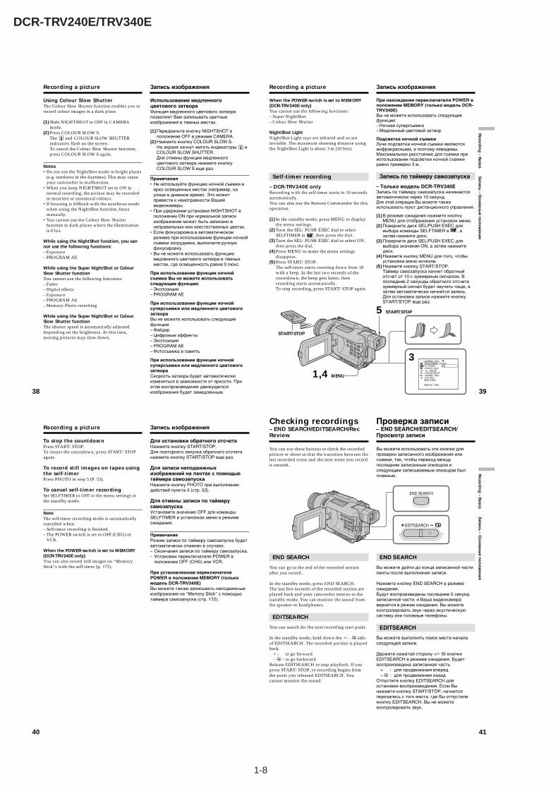
1-8
DCR-TRV240E/TRV340E
38
Recording a picture
Using Colour Slow ShutterThe Colour Slow Shutter function enables you torecord colour images in a dark place.
(1) Slide NIGHTSHOT to OFF in CAMERAmode.
(2) Press COLOUR SLOW S.The and COLOUR SLOW SHUTTERindicators flash on the screen.To cancel the Colour Slow Shutter function,press COLOUR SLOW S again.
Notes•Do not use the NightShot mode in bright places
(e.g. outdoors in the daytime). This may causeyour camcorder to malfunction.
•When you keep NIGHTSHOT set to ON innormal recording, the picture may be recordedin incorrect or unnatural colours.
•If focusing is difficult with the autofocus modewhen using the NightShot function, focusmanually.
•You cannot use the Colour Slow Shutterfunction in dark places where the illuminationis 0 lux.
While using the NightShot function, you cannot use the following functions:– Exposure– PROGRAM AE
While using the Super NightShot or ColourSlow Shutter functionYou cannot use the following functions:– Fader– Digital effects– Exposure– PROGRAM AE– Memory Photo recording
While using the Super NightShot or ColourSlow Shutter functionThe shutter speed is automatically adjusteddepending on the brightness. At this time,moving pictures may slow down.
Запись изображения
Использование медленногоцветового затвораФункция медленного цветового затворапозволяет Вам записывать цветныеизображения в темных местах.
(1) Передвиньте кнопку NIGHTSHOT вположение OFF в режиме CAMERA.
(2) Нажмите кнопку COLOUR SLOW S.На экране начнут мигать индикаторы иCOLOUR SLOW SHUTTER.Для отмены функции медленногоцветового затвора нажмите кнопкуCOLOUR SLOW S еще раз.
Примечания•Не используйте функцию ночной съемки в
ярко освещенных местах (например, наулице в дневное время). Это можетпривести к неисправности Вашейвидеокамеры.
•При удержании установки NIGHTSHOT вположении ON при нормальной записиизображение может быть записано внеправильных или неестественных цветах.
•Если фокусировка в автоматическомрежиме при использовании функции ночнойсъемки затруднена, выполните ручнуюфокусировку.
•Вы не можете использовать функциюмедленного цветового затвора в темныхместах, где освещенность равна 0 люкс.
При использовании функции ночнойсъемки Вы не можете использоватьследующие функции:– Экспозиция– PROGRAM AE
При использовании функции ночнойсуперсъемки или медленного цветовогозатвораВы не можете использовать следующиефункции:– Фейдер– Цифровые эффекты– Экспозиция– PROGRAM AE– Фотосъемка в память
При использовании функции ночнойсуперсъемки или медленного цветовогозатвораСкорость затвора будет автоматическиизменяться в зависимости от яркости. Приэтом воспроизведение движущегосяизображения будет замедленным. 39
Reco
rdin
g – B
asics Зап
ись
– Осн
ов
ны
е по
ло
жен
ия
When the POWER switch is set to MEMORY(DCR-TRV340E only)You cannot use the following functions:– Super NightShot– Colour Slow Shutter
NightShot LightNightShot Light rays are infrared and so areinvisible. The maximum shooting distance usingthe NightShot Light is about 3 m (10 feet).
Self-timer recording
– DCR-TRV340E onlyRecording with the self-timer starts in 10 secondsautomatically.You can also use the Remote Commander for thisoperation.
(1) In the standby mode, press MENU to displaythe menu settings.
(2) Turn the SEL/PUSH EXEC dial to selectSELFTIMER in , then press the dial.
(3) Turn the SEL/PUSH EXEC dial to select ON,then press the dial.
(4) Press MENU to make the menu settingsdisappear.
(5) Press START/STOP.The self-timer starts counting down from 10with a beep. In the last two seconds of thecountdown, the beep gets faster, thenrecording starts automatically.To stop recording, press START/STOP again.
Recording a picture
При нахождении переключателя POWER вположении MEMORY (только модель DCR-TRV340E)Вы не можете использовать следующиефункции:– Ночная суперсъемка– Медленный цветовой затвор
Подсветка ночной съемкиЛучи подсветки ночной съемки являютсяинфракрасными, и поэтому невидимы.Максимальное расстояние для съемки прииспользовании подсветки ночной съемкиравно примерно 3 м.
Запись по таймеру самозапуска
– Только модель DCR-TRV340EЗапись по таймеру самозапуска начинаетсяавтоматически через 10 секунд.Для этой операции Вы можете такжеиспользовать пульт дистанционного управления.
(1) В режиме ожидания нажмите кнопкуMENU для отображения установок меню.
(2) Поверните диск SEL/PUSH EXEC длявыбора команды SELFTIMER в , азатем нажмите диск.
(3) Поверните диск SEL/PUSH EXEC длявыбора значения ON, а затем нажмитедиск.
(4) Нажмите кнопку MENU для того, чтобыустановки меню исчезли.
(5) Нажмите кнопку START/STOP.Таймер самозапуска начнет обратныйотсчет от 10 с зуммерным сигналом. Впоследние 2 секунды обратного отсчетазуммерный сигнал будет звучать чаще, азатем автоматически начнется запись.Для остановки записи нажмите кнопкуSTART/STOP еще раз.
Запись изображения
3
[MENU] : END
CAMERA SET SELFTIMER D ZOOM PHOTO REC 16 : 9WIDE STEADYSHOT FRAME REC INT. REC RETURN
OFFON
1,4 MENU
START/STOP
5 START/STOP
40
To stop the countdownPress START/STOP.To restart the countdown, press START/STOPagain.
To record still images on tapes usingthe self-timerPress PHOTO in step 5 (P. 53).
To cancel self-timer recordingSet SELFTIMER to OFF in the menu settings inthe standby mode.
NoteThe self-timer recording mode is automaticallycancelled when:– Self-timer recording is finished.– The POWER switch is set to OFF (CHG) or
VCR.
When the POWER switch is set to MEMORY(DCR-TRV340E only)You can also record still images on “MemoryStick”s with the self-timer (p. 172).
Recording a picture
Для остановки обратного отсчетаНажмите кнопку START/STOP.Для повторного запуска обратного отсчетанажмите кнопку START/STOP еще раз.
Для записи неподвижныхизображений на лентах с помощьютаймера самозапускаНажмите кнопку PHOTO при выполнениидействий пункта 5 (стр. 53).
Для отмены записи по таймерусамозапускаУстановите значение OFF для командыSELFTIMER в установках меню в режимеожидания.
ПримечаниеРежим записи по таймеру самозапуска будетавтоматически отменен в случаях:– Окончания записи по таймеру самозапуска.– Установки переключателя POWER в
положение OFF (CHG) или VCR.
При установленном переключателеPOWER в положении MEMORY (толькомодель DCR-TRV340E)Вы можете также записывать неподвижныеизображения на “Memory Stick” с помощьютаймера самозапуска (стр. 172).
Запись изображения
41
Reco
rdin
g – B
asics За
пи
сь
– Ос
но
вн
ые
по
ло
же
ни
я
You can use these buttons to check the recordedpicture or shoot so that the transition between thelast recorded scene and the next scene you recordis smooth.
END SEARCH
You can go to the end of the recorded sectionafter you record.
In the standby mode, press END SEARCH.The last five seconds of the recorded section areplayed back and your camcorder returns to thestandby mode. You can monitor the sound fromthe speaker or headphones.
EDITSEARCH
You can search for the next recording start point.
In the standby mode, hold down the +/– 7 sideof EDITSEARCH. The recorded portion is playedback.
+ : to go forward– 7 : to go backward
Release EDITSEARCH to stop playback. If youpress START/STOP, re-recording begins fromthe point you released EDITSEARCH. Youcannot monitor the sound.
Checking recordings– END SEARCH/EDITSEARCH/RecReview
Вы можете использовать эти кнопки дляпроверки записанного изображения илисъемки, так, чтобы переход междупоследним записанным эпизодом иследующим записываемым эпизодом былплавным.
END SEARCH
Вы можете дойти до конца записанной частиленты после выполнения записи.
Нажмите кнопку END SEARCH в режимеожидания.Будут воспроизведены последние 5 секундзаписанной части, и Ваша видеокамеравернется в режим ожидания. Вы можетеконтролировать звук через акустическуюсистему или головные телефоны.
EDITSEARCH
Вы можете выполнять поиск места началаследующей записи.
Держите нажатой сторону +/– 7 кнопкиEDITSEARCH в режиме ожидания. Будетвоспроизведена записанная часть.
+ : для продвижения вперед– 7 : для продвижения назад
Отпустите кнопку EDITSEARCH дляостановки воспроизведения. Если Вынажмете кнопку START/STOP, начнетсяперезапись с того места, где Вы отпустиликнопку EDITSEARCH. Вы не можетеконтролировать звук.
Проверка записи– END SEARCH/EDITSEARCH/Просмотр записи
EDITSEARCH
END SEARCH
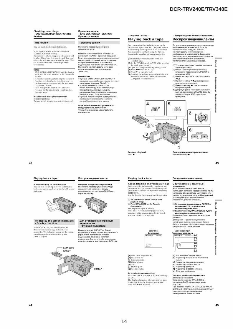
1-9
DCR-TRV240E/TRV340E
42
Checking recordings– END SEARCH/EDITSEARCH/RecReview
Rec Review
You can check the last recorded section.
In the standby mode, press the – 7 side ofEDITSEARCH momentarily.The section you have stopped most recently willbe played back for a few seconds, and then yourcamcorder will return to the standby mode. Youcan monitor the sound from the speaker orheadphones.
Notes•END SEARCH, EDITSEARCH and Rec Review
work only for tapes recorded in the Digital8 system.
•If you start recording after using the end searchfunction, occasionally, the transition betweenthe last scene you recorded and the next scenemay not be smooth.
•Once you eject the cassette after you haverecorded on the tape, the end search functiondoes not work.
If a tape has a blank portion betweenrecorded portionsThe end search function may not work correctly.
Проверка записи– END SEARCH/EDITSEARCH/Просмотр записи
Просмотр записи
Вы можете проверить последнююзаписанную часть.
Нажмите кратковременно сторону – 7кнопки EDITSEARCH в режиме ожидания.Будут воспроизведены последние несколькосекунд самой последней части, остановкукоторой Вы выполнили, а затем Вашавидеокамера вернется в режим ожидания.Вы можете контролировать звук черезакустическую систему или головныетелефоны.
Примечания•Функции END SEARCH, EDITSEARCH и
просмотр записи работают только для лент,записанных в системе Digital8 .
•Если Вы начинаете запись послеиспользования функции поиска конца,иногда переход между последнимзаписанным Вами эпизодом и следующимэпизодом может быть неплавным.
•Функция поиска конца не будет работатьпосле извлечения кассеты, на лентукоторой была выполнена запись.
Если на ленте имеются пустые частимежду записанными частямиФункция поиска конца может работатьнекорректно.
43
Playback – B
asics Во
сп
ро
изв
ед
ен
ие
– Ос
но
вн
ые
по
ло
же
ни
я
You can monitor the playback picture on theLCD screen. If you close the LCD panel, you canmonitor the playback picture in the viewfinder.You can control playback using the RemoteCommander supplied with your camcorder.
(1) Install the power source and insert therecorded tape.
(2) Set the POWER switch to VCR while pressingthe small green button.
(3) Open the LCD panel while pressing OPEN.(4) Press m to rewind the tape.(5) Press N to start playback.(6) To adjust the volume, press either of the two
buttons on VOLUME. When you close theLCD panel, sound is muted.
To stop playbackPress x.
— Playback – Basics —
Playing back a tape
Вы можете контролировать воспроизводимоеизображение на экране ЖКД. Если Вызакроете панель ЖКД, Вы можетеконтролировать воспроизводимоеизображение в видоискателе. Вы можетеконтролировать воспроизведение с помощьюпульта дистанционного управления,прилагаемого к Вашей видеокамере.
(1) Установите источник питания и вставьтезаписанную ленту.
(2) Нажав маленькую зеленую кнопку,установите переключатель POWER вположение VCR.
(3) Нажав кнопку OPEN, откройте панельЖКД.
(4) Нажмите кнопку m для ускореннойперемотки ленты назад.
(5) Нажмите кнопку N для включениявоспроизведения.
(6) Для регулировки громкости нажимайтеодну из двух кнопок VOLUME. Если Вызакроете панель ЖКД, звук будетприглушен.
Для остановки воспроизведенияНажмите кнопку x.
— Воспроизведение – Основные положения —
Воспроизведение ленты
3
54
2
6
1
VOLUME
REW PLAY
CAMERA
MEMORY
VCROFF(CHG
)
POWER
44
When monitoring on the LCD screenYou can turn the LCD panel over and move itback to the camcorder body with the LCD screenfacing out.
To display the screen indicators– Display function
Press DISPLAY on your camcorder or theRemote Commander supplied with yourcamcorder. The indicators appear on the screen.To make the indicators disappear, pressDISPLAY again.
Playing back a tape
DISPLAY
DISPLAY
DATA CODE
Во время контроля на экране ЖКДВы можете перевернуть панель ЖКД ипридвинуть ее обратно к корпусувидеокамеры, так что экран ЖКД будетобращен наружу.
Для отображения экранныхиндикаторов– Функция индикации
Нажмите кнопку DISPLAY на Вашейвидеокамере или на пульте дистанционногоуправления, прилагаемом к Вашейвидеокамере. На экране появятсяиндикаторы. Для того, чтобы индикаторыисчезли, нажмите еще раз кнопку DISPLAY.
Воспроизведение ленты
45
Playback – B
asics Во
сп
ро
изв
ед
ен
ие
– Ос
но
вн
ые
по
ло
же
ни
я
About date/time and various settingsYour camcorder automatically records not onlypictures on the tape but also the recording data(date/time or various settings when recorded)(Data code).Use the Remote Commander for this operation.
1 Set the POWER switch to VCR, thenplayback a tape.
2 Press DATA CODE on the RemoteCommander.
The display changes as follows:date/time t various settings (SteadyShot,exposure, white balance, gain, shutter speed,aperture value) t no indicator
[a] Time code/Tape counter[b] SteadyShot off[c] Exposure mode[d] White balance[e] Gain[f] Shutter speed[g] Aperture value
To not display various settingsSet DATA CODE to DATE in the menu settings(p. 136).The display changes as follows when you pressDATA CODE on the Remote Commander:date/time y no indicator
Playing back a tape
О дате/времени и различныхустановкахВаша видеокамера автоматическизаписывает не только изображения на ленту,но также и данные записи (дату/время илиразные установки при записи) (Код данных).Используйте пульт дистанционногоуправления для этой операции.
1 Установите переключатель POWER вположение VCR, затем начнитевоспроизведение ленты.
2 Нажмите кнопку DATA CODE на пультедистанционного управления.
Индикация будет изменяться следующимобразом:дата/время t различные установки(устойчивая съемка, экспозиция, балансбелого, усиление, скорость затвора, величинадиафрагмы) t без индикации
[a] Код времени/Счетчик ленты[b] Индикатор выключения устойчивой
съемки[c] Индикатор режима экспозиции[d] Индикатор баланса белого[e] Индикатор усиления[f] Индикатор скорости затвора[g] Величина диафрагмы
Для того, чтобы не отображалисьразличные установкиУстановите команду DATA CODE вположение DATE в установках меню(стр. 136).При нажатии кнопки DATA CODE на пультедистанционного управления индикация будетизменяться следующим образом:дата/время y без индикации
Воспроизведение ленты
Date/time/Дата/время
4 7 200212:05:56
0:00:23:0150min [a][b][c][d][e][f][g]
Various settings/Различные установки
50 AWBF1.6 9dB
AUTO
0:00:23:0150min

1-10
DCR-TRV240E/TRV340E
46
Playing back a tape
Notes on the data code function•The data code function works only for tapes
recorded in the Digital8 system.•Various settings of the recording data are not
recorded when recording images on “MemoryStick”s (DCR-TRV340E only).
Recording dataRecording data is your camcorder’s informationwhen you have recorded. In the recording mode,the recording data will not be displayed.
When you use data code function, bars(-- -- --) appear if:– A blank portion of the tape is being played
back.– The tape is unreadable due to tape damage or
noise.– The tape was recorded by a camcorder without
the date and time set.
Data codeWhen you connect your camcorder to the TV, thedata code appears on the TV screen.
Remaining battery time indicator duringplaybackThe indicator indicates the approximatecontinuous playback time. The indicator may notbe correct, depending on the conditions in whichyou are playing back. When you close the LCDpanel and open it again, it takes about oneminute for the correct remaining battery time tobe displayed.
Воспроизведение ленты
Примечания по функции кода данных• Функция кода данных работает только для
лент, записанных в системе Digital8 .•Различные установки данных записи не
записываются при записи изображений на“Memory Stick” (только модель DCR-TRV340E).
Данные записиДанные записи представляют собойинформацию о Вашей видеокамере привыполнении записи. В режиме записи данныезаписи отображаться не будут.
Если Вы используете функцию кодаданных, то появятся полосы (-- -- --), если:– Воспроизводится незаписанный участок на
ленте.– Лента является нечитаемой из-за
повреждения или помех.– Запись на ленту была выполнена
видеокамерой без установки даты ивремени.
Код данныхЕсли Вы подсоедините Вашу видеокамеру ктелевизору, код данных появится на экранетелевизора.
Индикатор оставшегося времени зарядабатарейного блока во времявоспроизведенияИндикатор оставшегося времени зарядабатарейного блока отображаетприблизительное время непрерывноговоспроизведения. Индикатор может бытьнеточным в зависимости от условий, вкоторых Вы выполняете воспроизведение.Когда Вы закрываете панель ЖКД иоткрываете её снова, требуется около однойминуты для правильного отображенияоставшегося времени заряда батарейногоблока в минутах.
47
Playback – B
asics Во
спр
ои
звед
ени
е – Осн
ов
ны
е по
ло
жен
ия
Playing back a tape
Various playback modes
To operate video control buttons, set the POWERswitch to VCR.
To playback pause (view a stillimage)Press X during playback. To resume normalplayback, press X or N.
To advance the tapePress M in the stop mode. To resume normalplayback, press N.
To rewind the tapePress m in the stop mode. To resume normalplayback, press N.
To change the playback directionPress on the Remote Commander duringplayback to reverse the playback direction. Toresume normal playback, press N.
To locate a scene monitoring thepicture (picture search)Keep pressing m or M during playback. Toresume normal playback, release the button.
To monitor high-speed pictures whileadvancing or rewinding the tape(skip scan)Keep pressing m while rewinding or M whileadvancing the tape. To resume rewinding oradvancing, release the button.
To view pictures at slow speed (slowplayback)Press y on the Remote Commander duringplayback. For slow playback in the reversedirection, press , then press y on the RemoteCommander. To resume normal playback, pressN.
Воспроизведение ленты
Различные режимывоспроизведения
Для использования кнопок видеоконтроляустановите переключатель POWER вположение VCR.
Для паузы воспроизведения (просмотранеподвижного изображения)Нажмите во время воспроизведения кнопкуX. Для возобновления обычного воспроизве-дения нажмите кнопку X или кнопку N.
Для ускоренной перемотки ленты впередНажмите в режиме остановки кнопку M.Для возобновления обычноговоспроизведения нажмите кнопку N.
Для ускоренной перемотки ленты назадНажмите в режиме остановки кнопку m.Для возобновления обычноговоспроизведения нажмите кнопку N.
Для изменения направлениявоспроизведенияНажмите кнопку на пультедистанционного управления во времявоспроизведения для изменениянаправления воспроизведения. Длявозобновления обычного воспроизведения,отпустите кнопку N.
Для отыскания эпизода во времяконтроля изображения (поискизображения)Держите нажатой кнопку m или M вовремя воспроизведения. Для восстановленияобычного воспроизведения отпустите кнопку.
Для контроля изображения навысокой скорости во времяускоренной перемотки ленты впередили назад (поиск методом прогона)Держите нажатой кнопку m во время уско-ренной перемотки ленты назад или кнопку Mво время ускоренной перемотки ленты вперед.Для возобновления обычной перемотки лентывперед или назад отпустите кнопку.
Для просмотра изображения назамедленной скорости (замедленноевоспроизведение)Нажмите во время воспроизведения кнопкуy на пульте дистанционного управления.Для замедленного воспроизведения вобратном направлении нажмите кнопку , азатем нажмите кнопку y на пультедистанционного управления. Длявозобновления обычного воспроизведениянажмите кнопку N.
48
Playing back a tape
To view pictures at double speedPress ×2 on the Remote Commander duringplayback. For double speed playback in thereverse direction, press , then press ×2 on theRemote Commander. To resume normalplayback, press N.
To view pictures frame-by-framePress C on the Remote Commander in theplayback pause mode. For frame-by-frameplayback in the reverse direction, press c. Toresume normal playback, press N.
To search the last scene recorded(END SEARCH)Press END SEARCH in the stop mode. The lastfive seconds of the recorded section plays backand stops.
In the various playback modes•Noise may appear when your camcorder plays
back tapes recorded in the Hi8/standard 8system.
•Sound is muted.•The previous recording may appear as a mosaic
image when playing back in the Digital8 system.
Notes on the playback pause mode•When the playback pause mode lasts for three
minutes, your camcorder automatically entersthe stop mode. To resume playback, press N.
•The previous recording may appear.
Slow playback for tapes recorded in theDigital8 systemSlow playback can be performed smoothly onyour camcorder; however, this function does notwork for an output signal through the DV IN/OUT jack.
When you play back a tape in reverseHorizontal noise may appear at the centre, or topand bottom of the screen. This is not amalfunction.
Воспроизведение ленты
Для просмотра изображения наудвоенной скоростиНажмите кнопку ×2 на пульте дистанционногоуправления во время воспроизведения. Длявоспроизведения на удвоенной скорости вобратном направлении нажмите кнопку , азатем кнопку ×2 на пульте дистанционногоуправления. Для возобновления обычноговоспроизведения нажмите кнопку N.
Для покадрового просмотраизображенияНажмите кнопку C на пульте дистанцион-ного управления в режиме паузы воспроиз-ведения. Для покадрового воспроизведенияв обратном направлении нажмите кнопку c.Для возобновления обычноговоспроизведения нажмите кнопку N.
Для поиска последнего записанногоэпизода (END SEARCH)Нажмите кнопку END SEARCH в режимеостановки. Будут воспроизведены последние5 секунд записанного участка на ленте, послечего воспроизведение остановится.
В различных режимах воспроизведения•Может появляться шум при
воспроизведении Вашей видеокамеройлент, записанных в системе Hi8/standard 8.
•Звук будет приглушен.•Изображение предыдущих записей может
стать мозаичным во времявоспроизведения в системе Digital8 .
Примечания по режиму паузывоспроизведения•Если режим паузы воспроизведения
продлится три минуты, ваша видеокамераавтоматически войдет в режим остановки.Для возобновления воспроизведениянажмите кнопку N.
•Может появляться предыдущая запись.
Замедленное воспроизведение для лент,записанных в системе Digital8 Замедленное воспроизведение может плавновыполняться на Вашей видеокамере; однако,эта функция не работает для выходногосигнала через гнездо DV IN/OUT.
При воспроизведении ленты в обратномнаправленииНа экране могут появиться горизонтальныепомехи по центру или же вверху и внизуэкрана. Это не является неисправностью. 49
Playback – B
asics Во
сп
ро
изв
ед
ен
ие
– Ос
но
вн
ые
по
ло
же
ни
я
Connect your camcorder to your TV with theA/V connecting cable supplied with yourcamcorder to watch playback pictures on the TVscreen. You can operate the video control buttonsin the same way as when you monitor playbackpictures on the LCD screen. When monitoringplayback pictures on the TV screen, werecommend that you power your camcorderfrom a wall socket using the AC power adaptor(p. 23). Refer to the operating instructions of yourTV.
Open the jack cover. Connect your camcorder tothe TV using the A/V connecting cable suppliedwith your camcorder. Then, set the TV/VCRselector on the TV to VCR.
If your TV is already connectedto a VCR
Connect your camcorder to the LINE IN input onthe VCR by using the A/V connecting cablesupplied with your camcorder. Set the inputselector on the VCR to LINE.
Viewing recordings onTV
Подсоедините Вашу видеокамеру к Вашемутелевизору с помощью соединительногокабеля аудио/видео, который прилагается кВашей видеокамере, для просмотравоспроизводимого изображения на экранетелевизора. Вы можете пользоватьсякнопками управления воспроизведениемтаким же образом, как при контролевоспроизводимого изображения на экранеЖКД. При контроле воспроизводимогоизображения на экране телевизорарекомендуется подключить питание к Вашейвидеокамере от электрической сети спомощью сетевого адаптера переменноготока (стр. 23). См. инструкцию поэксплуатации Вашего телевизора.
Откройте крышку гнезд. Подсоедините Вашувидеокамеру к телевизору с помощьюсоединительного кабеля аудио/видео,который прилагается к Вашей видеокамере.Затем установите селекторныйпереключатель TV/VCR на Вашем телевизорев положение VCR.
Если Ваш телевизор ужеподсоединен к КВМ
Подсоедините Вашу видеокамеру к входномугнезду LINE IN на КВМ с помощьюсоединительного кабеля аудио/видео,который прилагается к Вашей видеокамере.Установите селектор входного сигнала наКВМ в положение LINE.
Просмотр записей наэкране телевизора
S VIDEO
VIDEO
AUDIO
INS VIDEO
AUDIO / VIDEO
: Signal flow/Передача сигнала
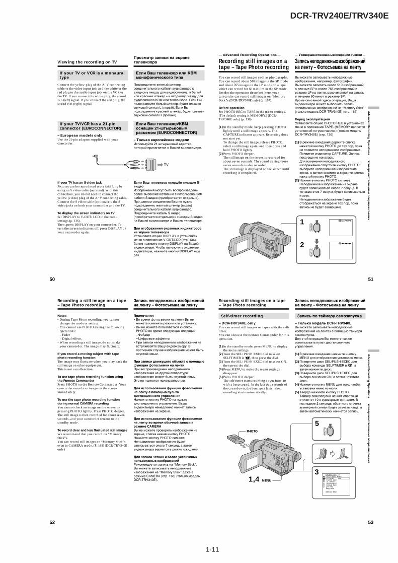
1-11
DCR-TRV240E/TRV340E
50
If your TV or VCR is a monauraltype
Connect the yellow plug of the A/V connectingcable to the video input jack and the white or thered plug to the audio input jack on the VCR orthe TV. If you connect the white plug, the soundis L (left) signal. If you connect the red plug, thesound is R (right) signal.
If your TV/VCR has a 21-pinconnector (EUROCONNECTOR)
– European models onlyUse the 21-pin adaptor supplied with yourcamcorder.
If your TV has an S video jackPictures can be reproduced more faithfully byusing an S video cable (optional). With thisconnection, you do not need to connect theyellow (video) plug of the A/V connecting cable.Connect the S video cable (optional) to the Svideo jacks on both your camcorder and the TV.
To display the screen indicators on TVSet DISPLAY to V-OUT/LCD in the menusettings (p. 136).Then, press DISPLAY on your camcorder. Toturn the screen indicators off, press DISPLAY onyour camcorder again.
Viewing the recording on TV
Если Ваш телевизор или КВМмонофонического типа
Подсоедините желтый штекерсоединительного кабеля аудио/видео квходному гнезду для видеосигнала, а белыйили красный штекер – к входному гнезду дляаудиосигнала КВМ или телевизора. Если Выподсоедините белый штекер, будет слышензвуковой сигнал L (левый). Если Выподсоедините красный штекер, будет слышензвуковой сигнал R (правый).
Если Ваш телевизор/КВМоснащен 21-штырьковымразъемом (EUROCONNECTOR)
– Только европейские моделиИспользуйте 21-штырьковый адаптер,который прилагается к Вашей видеокамере.
Если Ваш телевизор оснащён гнездом SвидеоИзображения могут быть воспроизведеныболее высококачественно с использованиемкабеля S видео (приобретается отдельно).При данном соединении Вам не нужноподсоединять желтый штекер (видео)соединительного кабеля аудио/видео.Подсоедините кабель S видео(приобретается отдельно) к гнездам S видеона Вашей видеокамере и Вашем телевизоре.
Для отображения экранных индикаторовна экране телевизораУстановите опцию DISPLAY в установкахменю в положение V-OUT/LCD (стр. 136).Затем нажмите кнопку DISPLAY на Вашейвидеокамере. Чтобы выключить экранныеиндикаторы, нажмите кнопку DISPLAY ещераз.
Просмотр записи на экранетелевизора
TV
51
Ad
vanced
Reco
rdin
g O
peratio
ns У
со
ве
рш
ен
ств
ов
ан
ны
е о
пе
ра
ци
и с
ъе
мк
и
You can record still images such as photographs.You can record about 510 images in the SP modeand about 765 images in the LP mode on a tapewhich can record for 60 minutes in the SP mode.Besides the operation described here, yourcamcorder can record still images on “MemoryStick”s (DCR-TRV340E only) (p. 167).
Before operationSet PHOTO REC to TAPE in the menu settings.(The default setting is MEMORY.) (DCR-TRV340E only) (p. 136)
(1) In the standby mode, keep pressing PHOTOlightly until a still image appears. TheCAPTURE indicator appears. Recording doesnot start yet.To change the still image, release PHOTO,select a still image again, and then press andhold PHOTO lightly.
(2) Press PHOTO deeper.The still image on the screen is recorded forabout seven seconds. The sound during thoseseven seconds is also recorded.The still image is displayed on the screen untilrecording is completed.
— Advanced Recording Operations —
Recording still images on atape – Tape Photo recording
1
•••••••
CAPTURE
2
PH
OTO
PH
OTO
Вы можете записывать неподвижныеизображения, например, фотографии.Вы можете записать около 510 изображенийв режиме SP и около 765 изображений врежиме LP на ленте, рассчитанной на записьв течение 60 минут в режиме SP.Кроме описанной здесь операции, Вашавидеокамера может выполнить записьнеподвижных изображений на “Memory Stick”(только модель DCR-TRV340E) (стр. 167).
Перед эксплуатациейУстановите опцию PHOTO REC в установкахменю в положение TAPE. (MEMORY являетсяустановкой по умолчанию.) (только модельDCR-TRV340E) (стр. 136)
(1) В режиме ожидания держите слегканажатой кнопку PHOTO до тех пор, покане появится неподвижное изображение.Появится индикатор CAPTURE. Записьпока еще не началась.Для изменения неподвижногоизображения отпустите кнопку PHOTO,выберите неподвижное изображениеснова, а затем нажмите и держите слегканажатой кнопку PHOTO.
(2) Нажмите кнопку PHOTO сильнее.Неподвижное изображение на экранебудет записываться около 7 секунд. Втечение этих 7 секунд будет записыватьсяи звук.Неподвижное изображение будетотображаться на экране тех пор, показапись не будет завершена.
— Усовершенствованные операции съемки —
Запись неподвижных изображенийна ленту – Фотосъемка на ленту
52
Recording a still image on a tape– Tape Photo recording
Notes•During Tape Photo recording, you cannot
change the mode or setting.•You cannot use PHOTO during the following
operations:– Fader– Digital effects
•When recording a still image, do not shakeyour camcorder. The image may fluctuate.
If you record a moving subject with tapephoto recording functionThe image may fluctuate when you play back thestill image on other equipment.This is not a malfunction.
To use tape photo recording function usingthe Remote CommanderPress PHOTO on the Remote Commander. Yourcamcorder records an image on the screenimmediately.
To use the tape photo recording functionduring normal CAMERA recordingYou cannot check an image on the screen bypressing PHOTO lightly. Press PHOTO deeper.The still image is then recorded for about sevenseconds, and your camcorder returns to thestandby mode.
To record clear and less fluctuated still imagesWe recommend that you record on “MemoryStick”s.You can record still images on “Memory Stick”seven in CAMERA mode. (P. 168) (DCR-TRV340Eonly)
Запись неподвижных изображенийна ленту – Фотосъемка на ленту
Примечания•Во время фотосъемки на ленту Вы не
можете изменять режим или установку.•Вы не можете пользоваться кнопкой
PHOTO во время следующих операций:– Фейдер– Цифровые эффекты
•При записи неподвижного изображения невстряхивайте Вашу видеокамеру. Впротивном случае изображение может бытьнеустойчивым.
При записи движущего объекта с помощьюфункции фотосъемки на лентуПри воспроизведении неподвижногоизображения на другой аппаратуреизображение может быть неустойчивым.Это не является неисправностью.
Для использования функции фотосъемкина ленту с помощью пультадистанционного управленияНажмите кнопку PHOTO на пультедистанционного управления. Вашавидеокамера немедленно начнет записьизображения на экране.
Для использования функции фотосъемкина ленту во время обычной записи врежиме CAMERAВы не можете проверить изображение наэкране, слегка нажав кнопку PHOTO.Нажмите кнопку PHOTO сильнее.Неподвижное изображение будетзаписываться около 7 секунд, а затемвидеокамера вернется в режим ожидания.
Для записи четких и более устойчивыхнеподвижных изображенийРекомендуется запись на “Memory Stick”.Вы можете записывать неподвижныеизображения на “Memory Stick” даже врежиме CAMERA (стр. 168) (только модельDCR-TRV340E).
53
Ad
vanced
Reco
rdin
g O
peratio
ns У
со
ве
рш
ен
ств
ов
ан
ны
е о
пе
ра
ци
и с
ъе
мк
и
Self-timer recording
– DCR-TRV340E onlyYou can record still images on tapes with the self-timer.You can also use the Remote Commander for thisoperation.
(1) In the standby mode, press MENU to displaythe menu settings.
(2) Turn the SEL/PUSH EXEC dial to selectSELFTIMER in , then press the dial.
(3) Turn the SEL/PUSH EXEC dial to select ON,then press the dial.
(4) Press MENU to make the menu settingsdisappear.
(5) Press PHOTO deeper.The self-timer starts counting down from 10with a beep sound. In the last two seconds ofthe countdown, the beep gets faster, thenrecording starts automatically.
Recording still images on a tape– Tape Photo recording
5
PH
OTO
3CAMERA SET SELFTIMER D ZOOM PHOTO REC 16 : 9WIDE STEADYSHOT FRAME REC INT. REC RETURN
[MENU] : END
OFFON
PHOTO
1,4 MENU
Запись по таймеру самозапуска
– Только модель DCR-TRV340EВы можете записывать неподвижныеизображения на лентах с помощью таймерасамозапуска.Для этой операции Вы можете такжеиспользовать пульт дистанционногоуправления.
(1) В режиме ожидания нажмите кнопкуMENU для отображения установок меню.
(2) Поверните диск SEL/PUSH EXEC длявыбора команды SELFTIMER в , азатем нажмите диск.
(3) Поверните диск SEL/PUSH EXEC длявыбора значения ON, а затем нажмитедиск.
(4) Нажмите кнопку MENU для того, чтобыустановки меню исчезли.
(5) Твердо нажмите кнопку PHOTO.Таймер самозапуска начнет обратныйотсчет от 10 с зуммерным сигналом. Впоследние 2 секунды обратного отсчетазуммерный сигнал будет звучать чаще, азатем автоматически начнется запись.
Запись неподвижных изображенийна ленту – Фотосъемка на ленту

1-12
DCR-TRV240E/TRV340E
54
To cancel self-timer recordingIn the standby mode, set SELFTIMER to OFF inthe menu settings.You cannot cancel self-timer recording using theRemote Commander.
NoteThe self-timer recording mode is automaticallycancelled when:– Self-timer recording is finished.– The POWER switch is set to OFF (CHG) or
VCR.
Recording still images on a tape– Tape Photo recording
Для отмены записи по таймерусамозапускаУстановите значение OFF для командыSELFTIMER в установках меню в режимеожидания.Вы не можете отменить запись по таймерусамозапуска, используя пультдистанционного управления.
ПримечаниеРежим записи по таймеру самозапуска будетавтоматически отменен в случаях:– Окончания записи по таймеру самозапуска.– Установки переключателя POWER в
положение OFF (CHG) или VCR.
Запись неподвижных изображенийна ленту – Фотосъемка на ленту
55
Ad
vanced
Reco
rdin
g O
peratio
ns У
сов
ерш
енств
ов
анн
ые о
пер
аци
и съ
емк
и
You can record a 16:9 wide picture to watch on a16:9 wide-screen TV (16:9WIDE).Black bands appear on the screen duringrecording in 16:9 WIDE mode [a]. The pictureduring playing back on a normal TV [b] or awide-screen TV [c] are compressed in thewidthwise direction. If you set the screen modeof the wide-screen TV to the full mode, you canwatch pictures of normal images [d].
(1) In the standby mode, press MENU to displaythe menu settings.
(2) Turn the SEL/PUSH EXEC to select 16:9WIDE in , then press the dial.
(3) Turn the SEL/PUSH EXEC to select ON, thenpress the dial.
To cancel the wide modeSet 16:9WIDE to OFF in the menu settings.
Using the wide mode
MENU
2CAMERA SET SELFTIMER D ZOOM PHOTO REC 16:9 WIDE STEADYSHOT FRAME REC INT. REC RETURN
[MENU] : END
OFFON
Вы можете записывать широкоформатноеизображение16:9 для просмотра наширокоэкранном телевизоре формата 16:9(16:9 WIDE).Во время записи в режиме 16:9 WIDE наэкране ЖКД появятся черные полосы [a].Изображение во время воспроизведения наобычном телевизоре [b] или наширокоэкранном телевизоре [c] будет сжатопо ширине. Если Вы установите режимэкрана широкоэкранного телевизора вполноэкранный режим, Вы сможетенаблюдать обычные изображения безискажений [d].
(1) В режиме ожидания нажмите кнопкуMENU для отображения установок меню.
(2) Поверните диск SEL/PUSH EXEC длявыбора команды 16:9 WIDE в , а затемнажмите диск.
(3) Поверните диск SEL/PUSH EXEC длявыбора значения ON, а затем нажмитедиск.
Для отмены широкоэкранногорежимаУстановите команду 16:9WIDE в положениеOFF в установках меню.
Использование широ-коэкранного режима
[a]
[c]
[b]
16:9WIDE [d]
56
In the wide modeYou cannot operate the following functions:– OLD MOVIE– BOUNCE– Memory Photo recording
During recordingYou cannot select or cancel the wide mode.When you cancel the wide mode, set yourcamcorder to the standby mode and then set16:9WIDE to OFF in the menu settings.
Using the wide mode
В широкоэкранном режимеВы не можете управлять следующимифункциями:– OLD MOVIE– BOUNCE– Фотосъемка в память
Во время записиВы не можете выбрать или отменитьширокоэкранный режим. Для отменыширокоэкранного режима установите Вашувидеокамеру в режим ожидания, а затемустановите опцию меню 16:9WIDE вположение OFF.
Использование широкоэкранногорежима
57
Ad
vanced
Reco
rdin
g O
peratio
ns У
со
ве
рш
ен
ств
ов
ан
ны
е о
пе
ра
ци
и с
ъе
мк
и
You can fade in or out to give your recording amore professional appearance.
MONOTONEWhen fading in, the picture gradually changesfrom black-and-white to colour.When fading out, the picture gradually changesfrom colour to black-and-white.
1) You can use this function when D ZOOM is setto OFF in the menu settings.
2) Fade in only
Using the faderfunction
Использованиефункции фейдера
Вы можете выполнять плавное введение иливыведение изображения, чтобы придатьВашей съемке профессиональный вид.
MONOTONEПри введении изображение будет постепенноизменяться от черно-белого до цветного.При выведении изображение будетпостепенно изменяться от цветного до черно-белого.
1) Вы можете использовать эту функцию приустановленном в положение OFF опции DZOOM в настройках меню.
2) Только введение изображения
[a] RECSTBY
RECSTBY[b]
FADER
M.FADER(mosaic)/(мозаика)
BOUNCE 1) 2)
OVERLAP 2)
WIPE 2)
DOT 2)
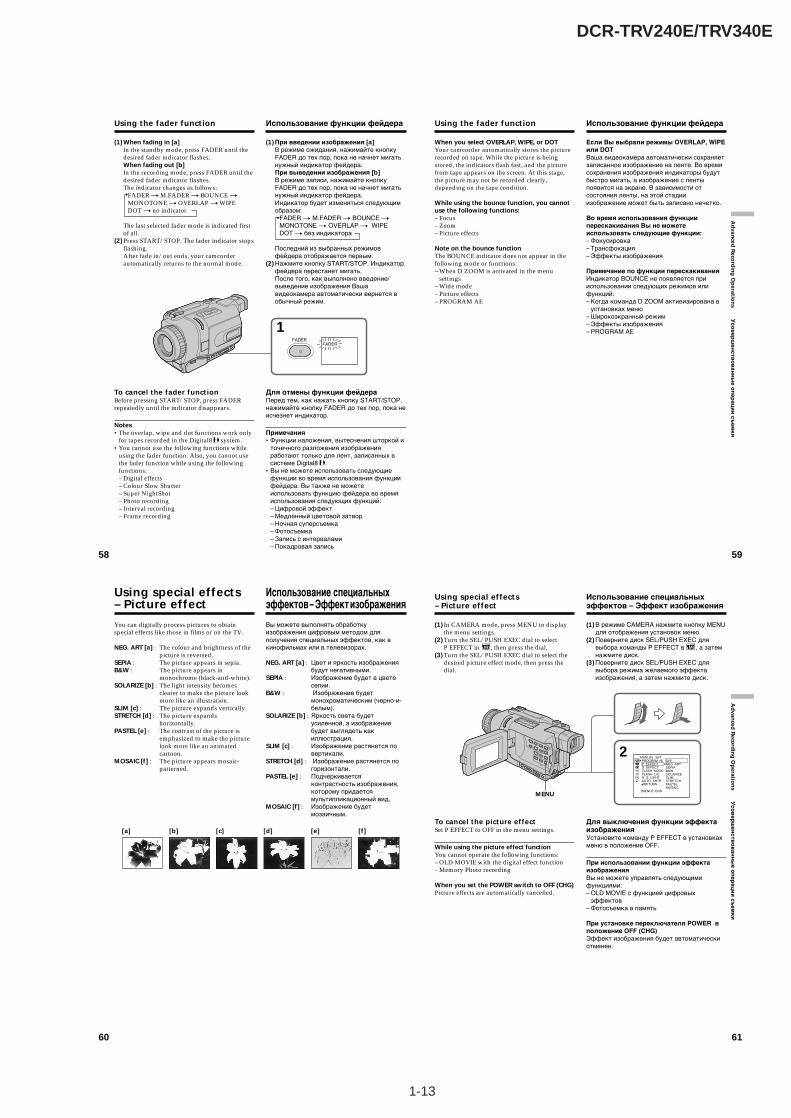
1-13
DCR-TRV240E/TRV340E
61
Ad
vanced
Reco
rdin
g O
peratio
ns У
со
ве
рш
ен
ств
ов
ан
ны
е о
пе
ра
ци
и с
ъе
мк
и
(1) In CAMERA mode, press MENU to displaythe menu settings.
(2) Turn the SEL/PUSH EXEC dial to selectP EFFECT in , then press the dial.
(3) Turn the SEL/PUSH EXEC dial to select thedesired picture effect mode, then press thedial.
To cancel the picture effectSet P EFFECT to OFF in the menu settings.
While using the picture effect functionYou cannot operate the following functions:– OLD MOVIE with the digital effect function– Memory Photo recording
When you set the POWER switch to OFF (CHG)Picture effects are automatically cancelled.
Using special effects– Picture effect
(1) В режиме CAMERA нажмите кнопку MENUдля отображения установок меню.
(2) Поверните диск SEL/PUSH EXEC длявыбора команды P EFFECT в , а затемнажмите диск.
(3) Поверните диск SEL/PUSH EXEC длявыбора режима желаемого эффектаизображения, а затем нажмите диск.
Для выключения функции эффектаизображенияУстановите команду P EFFECT в установкахменю в положение OFF.
При использовании функции эффектаизображенияВы не можете управлять следующимифункциями:– OLD MOVIE с функцией цифровых
эффектов– Фотосъемка в память
При установке переключателя POWER вположение OFF (CHG)Эффект изображения будет автоматическиотменен.
Использование специальныхэффектов – Эффект изображения
2MANUAL SET PROGRAM AE P EFFECT D EFFECT FLASH MODE FLASH LVL N. S. LIGHT AUTO SHTR RETURN
[MENU] : END
OFFNEG. ARTSEPIAB&WSOLARIZESLIMSTRETCHPASTELMOSAIC
MENU
58
(1) When fading in [a]In the standby mode, press FADER until thedesired fader indicator flashes.When fading out [b]In the recording mode, press FADER until thedesired fader indicator flashes.The indicator changes as follows:
FADER t M.FADER t BOUNCE tMONOTONE t OVERLAP t WIPEDOT t no indicator
The last selected fader mode is indicated firstof all.
(2) Press START/STOP. The fader indicator stopsflashing.After fade in/out ends, your camcorderautomatically returns to the normal mode.
To cancel the fader functionBefore pressing START/STOP, press FADERrepeatedly until the indicator disappears.
Notes•The overlap, wipe and dot functions work only
for tapes recorded in the Digital8 system.•You cannot use the following functions while
using the fader function. Also, you cannot usethe fader function while using the followingfunctions:– Digital effects– Colour Slow Shutter– Super NightShot– Photo recording– Interval recording– Frame recording
Using the fader function
(1) При введении изображения [a]В режиме ожидания, нажимайте кнопкуFADER до тех пор, пока не начнет мигатьнужный индикатор фейдера.При выведении изображения [b]В режиме записи, нажимайте кнопкуFADER до тех пор, пока не начнет мигатьнужный индикатор фейдера.Индикатор будет изменяться следующимобразом:
FADER t M.FADER t BOUNCE tMONOTONE t OVERLAP t WIPEDOT t без индикатора
Последний из выбранных режимовфейдера отображается первым.
(2) Нажмите кнопку START/STOP. Индикаторфейдера перестанет мигать.После того, как выполнено введение/выведение изображения Вашавидеокамера автоматически вернется вобычный режим.
Для отмены функции фейдераПеред тем, как нажать кнопку START/STOP,нажимайте кнопку FADER до тех пор, пока неисчезнет индикатор.
Примечания•Функции наложения, вытеснения шторкой и
точечного разложения изображенияработают только для лент, записанных всистеме Digital8 .
•Вы не можете использовать следующиефункции во время использования функциифейдера. Вы также не можетеиспользовать функцию фейдера во времяиспользования следующих функций:– Цифровой эффект– Медленный цветовой затвор– Ночная суперсъемка– Фотосъемка– Запись с интервалами– Покадровая запись
Использование функции фейдера
1FADER
FADER
59
Ad
vanced
Reco
rdin
g O
peratio
ns У
со
ве
рш
ен
ств
ов
ан
ны
е о
пе
ра
ци
и с
ъе
мк
и
Using the fader function
When you select OVERLAP, WIPE, or DOTYour camcorder automatically stores the picturerecorded on tape. While the picture is beingstored, the indicators flash fast, and the picturefrom tape appears on the screen. At this stage,the picture may not be recorded clearly,depending on the tape condition.
While using the bounce function, you cannotuse the following functions:– Focus– Zoom– Picture effects
Note on the bounce functionThe BOUNCE indicator does not appear in thefollowing mode or functions:– When D ZOOM is activated in the menu
settings– Wide mode– Picture effects– PROGRAM AE
Использование функции фейдера
Если Вы выбрали режимы OVERLAP, WIPEили DOTВаша видеокамера автоматически сохраняетзаписанное изображение на ленте. Во времясохранения изображения индикаторы будутбыстро мигать, а изображение с лентыпоявится на экране. В зависимости отсостояния ленты, на этой стадииизображение может быть записано нечетко.
Во время использования функцииперескакивания Вы не можетеиспользовать следующие функции:– Фокусировка– Трансфокация– Эффекты изображения
Примечание по функции перескакиванияИндикатор BOUNCE не появляется прииспользовании следующих режимов илифункций:– Когда команда D ZOOM активизирована в
установках меню– Широкоэкранный режим– Эффекты изображения– PROGRAM AE
60
You can digitally process pictures to obtainspecial effects like those in films or on the TV.
NEG. ART [a] : The colour and brightness of thepicture is reversed.
SEPIA : The picture appears in sepia.B&W : The picture appears in
monochrome (black-and-white).SOLARIZE [b] : The light intensity becomes
clearer to make the picture lookmore like an illustration.
SLIM [c] : The picture expands vertically.STRETCH [d] : The picture expands
horizontally.PASTEL [e] : The contrast of the picture is
emphasized to make the picturelook more like an animatedcartoon.
MOSAIC [f] : The picture appears mosaic-patterned.
Using special effects– Picture effect
[a] [b] [c] [d] [e] [f]
Вы можете выполнять обработкуизображения цифровым методом дляполучения специальных эффектов, как вкинофильмах или в телевизорах.
NEG. ART [a] : Цвет и яркость изображениябудут негативными.
SEPIA : Изображение будет в цветесепии.
B&W : Изображение будетмонохроматическим (черно-и-белым).
SOLARIZE [b] : Яркость света будетусиленной, а изображениебудет выглядеть какиллюстрация.
SLIM [c] : Изображение растянется повертикали.
STRETCH [d] : Изображение растянется погоризонтали.
PASTEL [e] : Подчеркиваетсяконтрастность изображения,которому придаетсямультипликационный вид.
MOSAIC [f] : Изображение будетмозаичным.
Использование специальныхэффектов – Эффект изображения
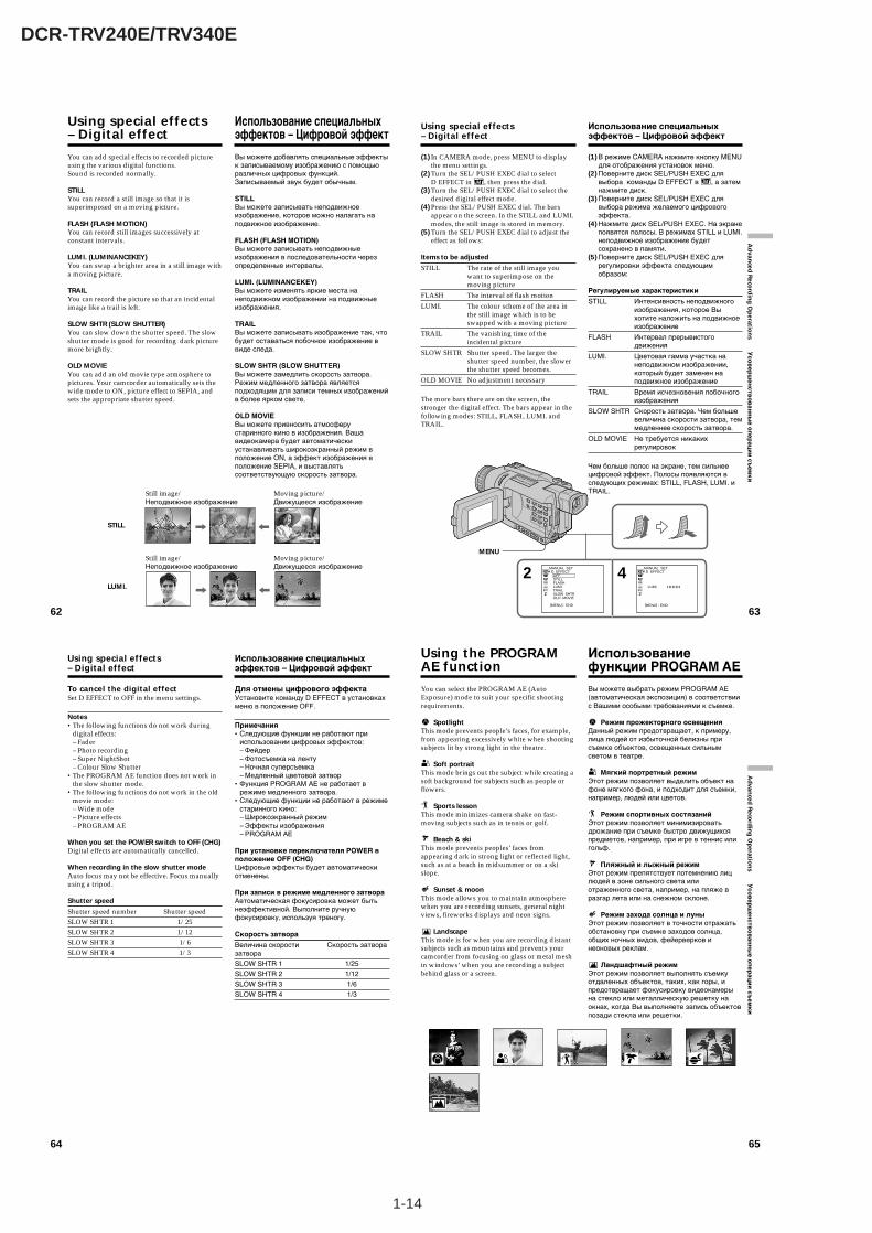
1-14
DCR-TRV240E/TRV340E
64
Using special effects– Digital effect
To cancel the digital effectSet D EFFECT to OFF in the menu settings.
Notes•The following functions do not work during
digital effects:– Fader– Photo recording– Super NightShot– Colour Slow Shutter
•The PROGRAM AE function does not work inthe slow shutter mode.
•The following functions do not work in the oldmovie mode:– Wide mode– Picture effects– PROGRAM AE
When you set the POWER switch to OFF (CHG)Digital effects are automatically cancelled.
When recording in the slow shutter modeAuto focus may not be effective. Focus manuallyusing a tripod.
Shutter speed
Shutter speed number Shutter speedSLOW SHTR 1 1/25SLOW SHTR 2 1/12SLOW SHTR 3 1/6SLOW SHTR 4 1/3
Использование специальныхэффектов – Цифровой эффект
Для отмены цифрового эффектаУстановите команду D EFFECT в установкахменю в положение OFF.
Примечания•Следующие функции не работают при
использовании цифровых эффектов:– Фейдер– Фотосъемка на ленту– Ночная суперсъемка– Медленный цветовой затвор
•Функция PROGRAM AE не работает врежиме медленного затвора.
•Следующие функции не работают в режиместаринного кино:– Широкоэкранный режим– Эффекты изображения– PROGRAM AE
При установке переключателя POWER вположение OFF (CHG)Цифровые эффекты будет автоматическиотменены.
При записи в режиме медленного затвораАвтоматическая фокусировка может бытьнеэффективной. Выполните ручнуюфокусировку, используя треногу.
Скорость затвора
Величина скорости Скорость затворазатвора
SLOW SHTR 1 1/25
SLOW SHTR 2 1/12
SLOW SHTR 3 1/6
SLOW SHTR 4 1/3
65
Ad
vanced
Reco
rdin
g O
peratio
ns У
со
ве
рш
ен
ств
ов
ан
ны
е о
пе
ра
ци
и с
ъе
мк
и
Using the PROGRAMAE function
You can select the PROGRAM AE (AutoExposure) mode to suit your specific shootingrequirements.
SpotlightThis mode prevents people’s faces, for example,from appearing excessively white when shootingsubjects lit by strong light in the theatre.
Soft portraitThis mode brings out the subject while creating asoft background for subjects such as people orflowers.
Sports lessonThis mode minimizes camera shake on fast-moving subjects such as in tennis or golf.
Beach & skiThis mode prevents peoples’ faces fromappearing dark in strong light or reflected light,such as at a beach in midsummer or on a skislope.
Sunset & moonThis mode allows you to maintain atmospherewhen you are recording sunsets, general nightviews, fireworks displays and neon signs.
LandscapeThis mode is for when you are recording distantsubjects such as mountains and prevents yourcamcorder from focusing on glass or metal meshin windows’ when you are recording a subjectbehind glass or a screen.
Использованиефункции PROGRAM AE
Вы можете выбрать режим PROGRAM AE(автоматическая экспозиция) в соответствиис Вашими особыми требованиями к съемке.
Режим прожекторного освещенияДанный режим предотвращает, к примеру,лица людей от избыточной белизны присъемке объектов, освещенных сильнымсветом в театре.
Мягкий портретный режимЭтот режим позволяет выделить объект нафоне мягкого фона, и подходит для съемки,например, людей или цветов.
Режим спортивных состязанийЭтот режим позволяет минимизироватьдрожание при съемке быстро движущихсяпредметов, например, при игре в теннис илигольф.
Пляжный и лыжный режимЭтот режим препятствует потемнению лицлюдей в зоне сильного света илиотраженного света, например, на пляже вразгар лета или на снежном склоне.
Режим захода солнца и луныЭтот режим позволяет в точности отражатьобстановку при съемке заходов солнца,общих ночных видов, фейерверков инеоновых реклам.
Ландшафтный режимЭтот режим позволяет выполнять съемкуотдаленных объектов, таких, как горы, ипредотвращает фокусировку видеокамерына стекло или металлическую решетку наокнах, когда Вы выполняете запись объектовпозади стекла или решетки.
62
Using special effects– Digital effect
You can add special effects to recorded pictureusing the various digital functions.Sound is recorded normally.
STILLYou can record a still image so that it issuperimposed on a moving picture.
FLASH (FLASH MOTION)You can record still images successively atconstant intervals.
LUMI. (LUMINANCEKEY)You can swap a brighter area in a still image witha moving picture.
TRAILYou can record the picture so that an incidentalimage like a trail is left.
SLOW SHTR (SLOW SHUTTER)You can slow down the shutter speed. The slowshutter mode is good for recording dark picturemore brightly.
OLD MOVIEYou can add an old movie type atmosphere topictures. Your camcorder automatically sets thewide mode to ON, picture effect to SEPIA, andsets the appropriate shutter speed.
STILL
LUMI.
Still image/ Moving picture/Неподвижное изображение Движущееся изображение
Still image/ Moving picture/Неподвижное изображение Движущееся изображение
Использование специальныхэффектов – Цифровой эффект
Вы можете добавлять специальные эффектык записываемому изображению с помощьюразличных цифровых функций.Записываемый звук будет обычным.
STILLВы можете записывать неподвижноеизображение, которое можно налагать наподвижное изображение.
FLASH (FLASH MOTION)Вы можете записывать неподвижныеизображения в последовательности черезопределенные интервалы.
LUMI. (LUMINANCEKEY)Вы можете изменять яркие места нанеподвижном изображении на подвижныеизображения.
TRAILВы можете записывать изображение так, чтобудет оставаться побочное изображение ввиде следа.
SLOW SHTR (SLOW SHUTTER)Вы можете замедлить скорость затвора.Режим медленного затвора являетсяподходящим для записи темных изображенийв более ярком свете.
OLD MOVIEВы можете привносить атмосферустаринного кино в изображения. Вашавидеокамера будет автоматическиустанавливать широкоэкранный режим вположение ON, а эффект изображения вположение SEPIA, и выставлятьсоответствующую скорость затвора.
63
Ad
vanced
Reco
rdin
g O
peratio
ns У
сов
ерш
енств
ов
анн
ые о
пер
аци
и съ
емк
иUsing special effects– Digital effect
(1) In CAMERA mode, press MENU to displaythe menu settings.
(2) Turn the SEL/PUSH EXEC dial to selectD EFFECT in , then press the dial.
(3) Turn the SEL/PUSH EXEC dial to select thedesired digital effect mode.
(4) Press the SEL/PUSH EXEC dial. The barsappear on the screen. In the STILL and LUMI.modes, the still image is stored in memory.
(5) Turn the SEL/PUSH EXEC dial to adjust theeffect as follows:
Items to be adjusted
STILL The rate of the still image youwant to superimpose on themoving picture
FLASH The interval of flash motion
LUMI. The colour scheme of the area inthe still image which is to beswapped with a moving picture
TRAIL The vanishing time of theincidental picture
SLOW SHTR Shutter speed. The larger theshutter speed number, the slowerthe shutter speed becomes.
OLD MOVIE No adjustment necessary
The more bars there are on the screen, thestronger the digital effect. The bars appear in thefollowing modes: STILL, FLASH, LUMI. andTRAIL.
42 MANUAL SET D EFFECT OFF STILL FLASH LUMI. TRAIL SLOW SHTR OLD MOVIE
[MENU] : END [MENU] : END
MANUAL SET D EFFECT
LUMI. I I I I I I I I ¥ ¥ ¥ ¥ ¥ ¥ ¥ ¥
MENU
Использование специальныхэффектов – Цифровой эффект
(1) В режиме CAMERA нажмите кнопку MENUдля отображения установок меню.
(2) Поверните диск SEL/PUSH EXEC длявыбора команды D EFFECT в , а затемнажмите диск.
(3) Поверните диск SEL/PUSH EXEC длявыбора режима желаемого цифровогоэффекта.
(4) Нажмите диск SEL/PUSH EXEC. На экранепоявятся полосы. В режимах STILL и LUMI.неподвижное изображение будетсохранено в памяти.
(5) Поверните диск SEL/PUSH EXEC длярегулировки эффекта следующимобразом:
Регулируемые характеристики
STILL Интенсивность неподвижногоизображения, которое Выхотите наложить на подвижноеизображение
FLASH Интервал прерывистогодвижения
LUMI. Цветовая гамма участка нанеподвижном изображении,который будет заменен наподвижное изображение
TRAIL Время исчезновения побочногоизображения
SLOW SHTR Скорость затвора. Чем большевеличина скорости затвора, теммедленнее скорость затвора.
OLD MOVIE Не требуется никакихрегулировок
Чем больше полос на экране, тем сильнеецифровой эффект. Полосы появляются вследующих режимах: STILL, FLASH, LUMI. иTRAIL.
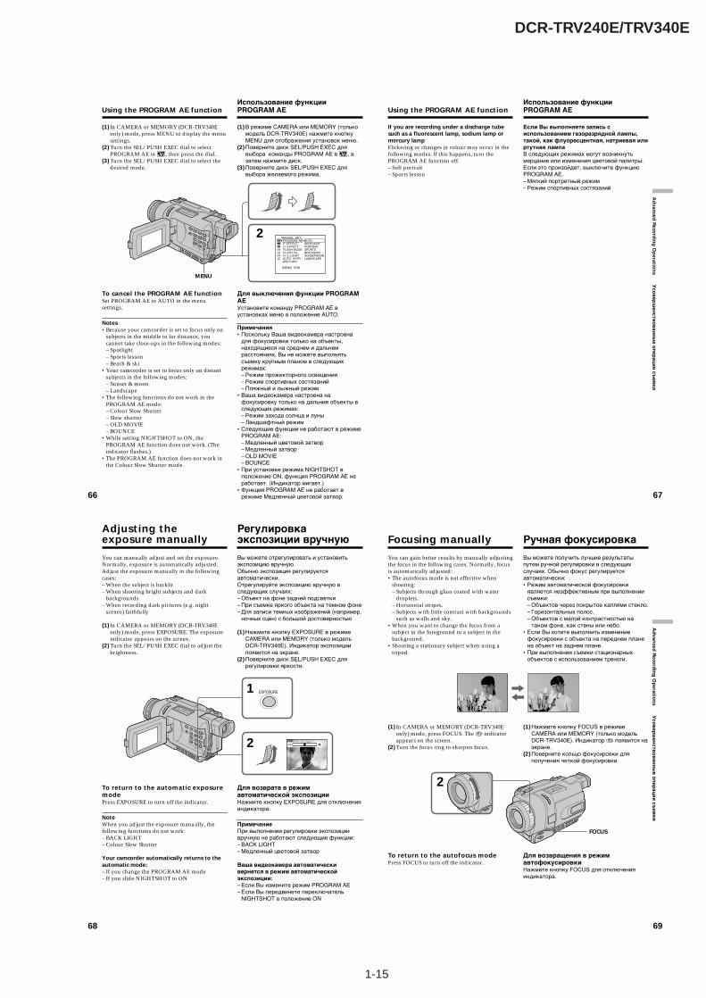
1-15
DCR-TRV240E/TRV340E
66
(1) In CAMERA or MEMORY (DCR-TRV340Eonly) mode, press MENU to display the menusettings.
(2) Turn the SEL/PUSH EXEC dial to selectPROGRAM AE in , then press the dial.
(3) Turn the SEL/PUSH EXEC dial to select thedesired mode.
To cancel the PROGRAM AE functionSet PROGRAM AE to AUTO in the menusettings.
Notes•Because your camcorder is set to focus only on
subjects in the middle to far distance, youcannot take close-ups in the following modes:– Spotlight– Sports lesson– Beach & ski
•Your camcorder is set to focus only on distantsubjects in the following modes:– Sunset & moon– Landscape
•The following functions do not work in thePROGRAM AE mode:– Colour Slow Shutter– Slow shutter– OLD MOVIE– BOUNCE
•While setting NIGHTSHOT to ON, thePROGRAM AE function does not work. (Theindicator flashes.)
•The PROGRAM AE function does not work inthe Colour Slow Shutter mode.
Using the PROGRAM AE function
(1) В режиме CAMERA или MEMORY (толькомодель DCR-TRV340E) нажмите кнопкуMENU для отображения установок меню.
(2) Поверните диск SEL/PUSH EXEC длявыбора команды PROGRAM AE в , азатем нажмите диск.
(3) Поверните диск SEL/PUSH EXEC длявыбора желаемого режима.
Для выключения функции PROGRAMAEУстановите команду PROGRAM AE вустановках меню в положение AUTO.
Примечания•Поскольку Ваша видеокамера настроена
для фокусировки только на объекты,находящиеся на среднем и дальнемрасстояниях, Вы не можете выполнятьсъемку крупным планом в следующихрежимах:– Режим прожекторного освещения– Режим спортивных состязаний– Пляжный и лыжный режим
•Ваша видеокамера настроена нафокусировку только на дальние объекты вследующих режимах:– Режим захода солнца и луны– Ландшафтный режим
•Следующие функции не работают в режимеPROGRAM AE:– Медленный цветовой затвор– Медленный затвор– OLD MOVIE– BOUNCE
•При установке режима NIGHTSHOT вположение ON, функция PROGRAM AE неработает. (Индикатор мигает.)
•Функция PROGRAM AE не работает врежиме Медленный цветовой затвор.
Использование функцииPROGRAM AE
2 MANUAL SET PROGRAM AE P EFFECT D EFFECT FLASH MODE FLASH LVL N. S. LIGHT AUTO SHTR RETURN
[MENU] : END
AUTOSPOTLIGHTPORTRAITSPORTSBEACH&SKISUNSETMOONLANDSCAPE
MENU
67
Ad
vanced
Reco
rdin
g O
peratio
ns У
со
ве
рш
ен
ств
ов
ан
ны
е о
пе
ра
ци
и с
ъе
мк
и
Using the PROGRAM AE function
If you are recording under a discharge tubesuch as a fluorescent lamp, sodium lamp ormercury lampFlickering or changes in colour may occur in thefollowing modes. If this happens, turn thePROGRAM AE function off.– Soft portrait– Sports lesson
Если Вы выполняете запись сиспользованием газоразрядной лампы,такой, как флуоресцентная, натриевая илиртутная лампаВ следующих режимах могут возникнутьмерцание или изменения цветовой палитры.Если это произойдет, выключите функциюPROGRAM AE.– Мягкий портретный режим– Режим спортивных состязаний
Использование функцииPROGRAM AE
68
You can manually adjust and set the exposure.Normally, exposure is automatically adjusted.Adjust the exposure manually in the followingcases:– When the subject is backlit– When shooting bright subjects and dark
backgrounds– When recording dark pictures (e.g. night
scenes) faithfully
(1) In CAMERA or MEMORY (DCR-TRV340Eonly) mode, press EXPOSURE. The exposureindicator appears on the screen.
(2) Turn the SEL/PUSH EXEC dial to adjust thebrightness.
To return to the automatic exposuremodePress EXPOSURE to turn off the indicator.
NoteWhen you adjust the exposure manually, thefollowing functions do not work:– BACK LIGHT– Colour Slow Shutter
Your camcorder automatically returns to theautomatic mode:– If you change the PROGRAM AE mode– If you slide NIGHTSHOT to ON
Adjusting theexposure manually
Вы можете отрегулировать и установитьэкспозицию вручную.Обычно экспозиция регулируетсяавтоматически.Отрегулируйте экспозицию вручную вследующих случаях:– Объект на фоне задней подсветки– При съемке яркого объекта на темном фоне– Для записи темных изображений (например,
ночных сцен) с большой достоверностью
(1) Нажмите кнопку EXPOSURE в режимеCAMERA или MEMORY (только модельDCR-TRV340E). Индикатор экспозициипоявится на экране.
(2) Поверните диск SEL/PUSH EXEC длярегулировки яркости.
Для возврата в режимавтоматической экспозицииНажмите кнопку EXPOSURE для отключенияиндикатора.
ПримечаниеПри выполнении регулировки экспозициивручную не работают следующие функции:– BACK LIGHT– Медленный цветовой затвор
Ваша видеокамера автоматическивернется в режим автоматическойэкспозиции:– Если Вы измените режим PROGRAM AE– Если Вы передвинете переключатель
NIGHTSHOT в положение ON
Регулировкаэкспозиции вручную
1
2
EXPOSURE
69
Ad
vanced
Reco
rdin
g O
peratio
ns У
со
ве
рш
ен
ств
ов
ан
ны
е о
пе
ра
ци
и с
ъе
мк
и
You can gain better results by manually adjustingthe focus in the following cases. Normally, focusis automatically adjusted:•The autofocus mode is not effective when
shooting:– Subjects through glass coated with water
droplets.– Horizontal stripes.– Subjects with little contrast with backgrounds
such as walls and sky.•When you want to change the focus from a
subject in the foreground to a subject in thebackground.
•Shooting a stationary subject when using atripod.
(1) In CAMERA or MEMORY (DCR-TRV340Eonly) mode, press FOCUS. The 9 indicatorappears on the screen.
(2) Turn the focus ring to sharpen focus.
To return to the autofocus modePress FOCUS to turn off the indicator.
Focusing manually
Вы можете получить лучшие результатыпутем ручной регулировки в следующихслучаях. Обычно фокус регулируетсяавтоматически:•Режим автоматической фокусировки
является неэффективным при выполнениисъемки:– Объектов через покрытое каплями стекло.– Горизонтальных полос.– Объектов с малой контрастностью на
таком фоне, как стены или небо.•Если Вы хотите выполнить изменение
фокусировки с объекта на переднем планена объект на заднем плане.
•При выполнении съемки стационарныхобъектов с использованием треноги.
(1) Нажмите кнопку FOCUS в режимеCAMERA или MEMORY (только модельDCR-TRV340E). Индикатор 9 появится наэкране.
(2) Поверните кольцо фокусировки дляполучения четкой фокусировки.
Для возвращения в режимавтофокусировкиНажмите кнопку FOCUS для отключенияиндикатора.
Ручная фокусировка
2
FOCUS
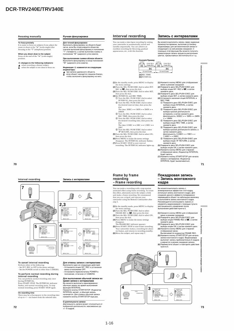
1-16
DCR-TRV240E/TRV340E
72
Interval recording
To cancel interval recordingPerform either of the following:– Set INT. REC to OFF in the menu settings.– Set the POWER switch to other than CAMERA.
To perform normal recording duringinterval recordingYou can perform normal recording only onceduring INTERVAL.Press START/STOP. The INTERVAL indicatorflashes, and normal recording starts. To stopnormal recording, press START/STOP again.
On recording timeThere may be a discrepancy in the recording timeof up to +/– six frames from the selected time.
5
7
CAMERA SETSELFT I MERD ZOOMPHOTO REC16 : 9W I DESTEADYSHOTFRAME REC I NT. REC RETURN
ON
[MENU] : END
CAMERA SETSELFT I MERD ZOOMPHOTO REC16 : 9W I DESTEADYSHOTFRAME REC I NT. REC RETURN
[MENU] : END
CAMERA SETSELFT I MERD ZOOMPHOTO REC16 : 9W I DESTEADYSHOTFRAME REC I NT. REC RETURN
ONOFFSET
OFF
[MENU] : END
CAMERA SET I NT. REC I NTERVAL REC T I ME RETURN
30SEC
[MENU] : END
CAMERA SET I NT. REC I NTERVAL REC T I ME RETURN
30SEC 1M I N 5M I N10M I N
[MENU] : END
CAMERA SET I NT. REC I NTERVAL REC T I ME RETURN
0 . 5SEC
[MENU] : END
CAMERA SET I NT. REC I NTERVAL REC T I ME RETURN
0 . 5SEC 1SEC1 . 5SEC 2SEC
[MENU] : END
2,3
4
6 I NTERVAL
STBY
MENU
Запись с интервалами
Для отмены записи с интерваламиВыполните одно из следующих действий:– Установите опцию INT. REC в установках
меню в положение OFF.– Установите переключатель POWER в
положение, отличное от CAMERA.
Для выполнения обычной записи вовремя записи с интерваламиВы можете выполнить единовременнообычную запись во время выполненияфункции INTERVAL.Нажмите кнопку START/STOP. ИндикаторINTERVAL мигает, и обычная записьначинается. Для отмены обычной записинажмите кнопку START/STOP еще раз.
О длительности записиДлительность записи может отклоняться отвыбранной длительности, максимально до+/– 6 кадров.
73
Ad
vanced
Reco
rdin
g O
peratio
ns У
со
ве
рш
ен
ств
ов
ан
ны
е о
пе
ра
ци
и с
ъе
мк
и
Frame by framerecording– Frame recording
5
4STBY
FRAME REC
MENU
3 CAMERA SETSELFT I MERD ZOOMPHOTO REC16 : 9W I DESTEADYSHOTFRAME REC I NT. REC RETURN
ON
[MENU] : END
CAMERA SETSELFT I MERD ZOOMPHOTO REC16 : 9W I DESTEADYSHOTFRAME REC I NT. REC RETURN
OFFON
[MENU] : END
You can make a recording with a stop-motionanimated effect using frame recording. To createthis effect, alternately move the subject a littleand make a frame recording. We recommendthat you use a tripod, and operate yourcamcorder using the Remote Commander afterstep 5.
(1) In the standby mode, press MENU to displaythe menu settings.
(2) Turn the SEL/PUSH EXEC dial to selectFRAME REC in , then press the dial.
(3) Turn the SEL/PUSH EXEC dial to select ON,then press the dial.
(4) Press MENU to make the menu settingsdisappear.The FRAME REC indicator appears.
(5) Press START/STOP to start frame recording.Your camcorder makes a recording for aboutsix frames, and returns to recording standby.
(6) Move the subject, and repeat step 5.
Покадровая запись– Запись монтажногокадра
Вы можете выполнить запись санимированным эффектом стоп-кадра,используя запись монтажного кадра. Длясоздания данного эффекта попеременноперемещайте объект на небольшую величинуи выполняйте запись монтажного кадра.Рекомендуется использовать треногу иуправлять видеокамерой с помощью пультадистанционного управления послевыполнения действий пункта 5.
(1) Нажмите кнопку MENU для отображенияменю в режиме ожидания.
(2) Поверните диск SEL/PUSH EXEC длявыбора опции FRAME REC в , а затемнажмите диск.
(3) Поверните диск SEL/PUSH EXEC длявыбора опции ON, а затем нажмите диск.
(4) Нажмите кнопку MENU для стиранияотображения меню.Высвечивается индикатор FRAME REC.
(5) Нажмите кнопку START/STOP для началазаписи монтажного кадра. Видеокамеравыполнит запись приблизительно 6 кадрови вернется в режим ожидания записи.
(6) Переместите объект и повторите действияпункта 5.
70
Focusing manually
To focus preciselyIt is easier to focus on subjects if you adjust thezoom to shoot at the “W” (wide-angle) afterfocusing at the “T” (telephoto) position.
When you shoot close to the subjectFocus at the end of the “W” (wide-angle)position.
9 changes to the following indicators:when recording a distant subject.when the subject is too close to focus on.
Ручная фокусировка
Для точной фокусировкиВыполнить фокусировку на объекте будетлегче, если Вы отрегулируете объектив,сначала выполнив фокусировку в положении“Т” (телефото), а затем выполнив съемку вположении “W” (широкого угла охвата).
При выполнении съемки вблизи объектаВыполните фокусировку в конце положения“W” (широкого угла охвата).
Индикация 9 изменится на следующиеиндикаторы:
при записи удаленного объекта.если объект находится слишком близко,чтобы выполнить фокусировку на него.
71
Ad
vanced
Reco
rdin
g O
peratio
ns У
сов
ерш
енств
ов
анн
ые о
пер
аци
и съ
емк
и
You can make a time-lapse recording by settingyour camcorder to automatically record andstandby sequentially. You can achieve anexcellent recording for flowering, gradualappearances, etc., with this function.
(1) In the standby mode, press MENU to displaythe menu settings.
(2) Turn the SEL/PUSH EXEC dial to select INT.REC in , then press the dial.
(3) Turn the SEL/PUSH EXEC dial to select SET,then press the dial.
(4) Set INTERVAL and REC TIME.1 Turn the SEL/PUSH EXEC dial to select
INTERVAL, then press the dial.2 Turn the SEL/PUSH EXEC dial to select
the desired interval time, then press thedial.The time: 30SEC y 1MIN y 5MIN y10MIN
3 Turn the SEL/PUSH EXEC dial to selectREC TIME, then press the dial.
4 Turn the SEL/PUSH EXEC dial to selectthe desired recording time, then press thedial.The time: 0.5SEC y 1SEC y 1.5SEC y2SEC
5 Turn the SEL/PUSH EXEC dial to select RETURN, then press the dial.
(5) Turn the SEL/PUSH EXEC dial to select ON,then press the dial.
(6) Press MENU to make the menu settingsdisappear. The INTERVAL indicator flashes.
(7) Press START/STOP to start intervalrecording. The INTERVAL indicator lights up.
Interval recording
Вы можете выполнять запись через заданныепромежутки времени, выполнив установкувидеокамеры для автоматической записи иследующего за ней режима ожидания. Спомощью этой функции Вы можете получитьпревосходную запись процесса распусканияцветов, чрезвычайных обстоятельств и т.д.
(1) Нажмите кнопку MENU для отображенияменю в режиме ожидания.
(2) Поверните диск SEL/PUSH EXEC длявыбора опции INT. REC в , а затемнажмите диск.
(3) Поверните диск SEL/PUSH EXEC длявыбора опции SET, а затем нажмите диск.
(4) Установите значения опций INTERVAL иREC TIME.1 Поверните диск SEL/PUSH EXEC для
выбора опции INTERVAL, а затемнажмите диск.
2 Поверните диск SEL/PUSH EXEC длявыбора нужной длительностиинтервала, а затем нажмите диск.Длительность: 30SEC y 1MIN y 5MINy 10MIN
3 Поверните диск SEL/PUSH EXEC длявыбора опции REC TIME, а затемнажмите диск.
4 Поверните диск SEL/PUSH EXEC длявыбора нужной длительности записи, азатем нажмите диск.Длительность: 0.5SEC y 1SEC y1.5SEC y 2SEC
5 Поверните диск SEL/PUSH EXEC длявыбора опции RETURN, а затемнажмите диск.
(5) Поверните диск SEL/PUSH EXEC длявыбора опции ON, а затем нажмите диск.
(6) Нажмите кнопку MENU для стиранияотображения меню. Индикатор INTERVALбудет мигать.
(7) Нажмите кнопку START/STOP для началазаписи с интервалом. ИндикаторINTERVAL будет высвечиваться.
Запись с интервалами
Example/Пример
[a]REC TIME[b]INTERVAL
10 min/10 мин10 min/10 мин
1 s/1с 1 s/1 с9 min 59 s/9 мин 59 с
9 min 59 s/9 мин 59 с[a] [a]
[b] [b]
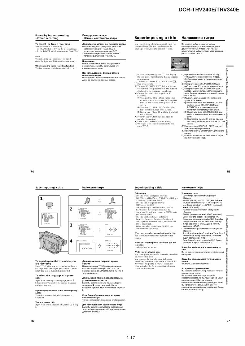
1-17
DCR-TRV240E/TRV340E
74
Frame by frame recording– Frame recording
To cancel the frame recordingPerform either of the following:– Set FRAME REC to OFF in the menu settings.– Set the POWER switch to other than CAMERA.
NoteThe remaining tape time is not indicatedcorrectly if you use this function continuously.
When using the frame recording functionThe last recorded cut is longer than other cuts.
Покадровая запись– Запись монтажного кадра
Для отмены записи монтажного кадраВыполните одно из следующих действий:– Установите опцию FRAME REC в
установках меню в положение OFF.– Установите переключатель POWER в
положение, отличное от CAMERA.
ПримечаниеВремя оставшейся ленты отображаетсянеправильно, если Вы используете этуфункцию непрерывно.
При использовании функции записимонтажного кадраПоследний из записанных монтажных кадровдлиннее других монтажных кадров.
75
Ad
vanced
Reco
rdin
g O
peratio
ns У
со
ве
рш
ен
ств
ов
ан
ны
е о
пе
ра
ци
и с
ъе
мк
и
You can select one of eight preset titles and twocustom titles (p. 78). You can also select thelanguage, colour, size and position of titles.
(1) In the standby mode, press TITLE to displaythe title menu. The title menu display appearson the screen.
(2) Turn the SEL/PUSH EXEC dial to select ,then press the dial.
(3) Turn the SEL/PUSH EXEC dial to select thedesired title, then press the dial. The titles aredisplayed in the language you selected.
(4) Change the colour, size, or position, ifnecessary.1 Turn the SEL/PUSH EXEC dial to select
COLOUR, SIZE, or POSITION, then pressthe dial. The selected item appears on thescreen.
2 Turn the SEL/PUSH EXEC dial to selectthe desired item, then press the dial.
3 Repeat steps 1 and 2 until the title is laidout as desired.
(5) Press the SEL/PUSH EXEC dial again tocomplete the setting.
(6) Press START/STOP to start recording.(7) When you want to stop recording the title,
press TITLE.
Superimposing a title
Вы можете выбрать один из восьмипредварительно установленных титров идвух собственных титров (стр. 78). Выможете также выбрать язык, цвет, размер ирасположение титров.
(1) В режиме ожидания нажмите кнопкуTITLE для отображения меню титров.Отображение меню титров появится наэкране.
(2) Поверните диск SEL/PUSH EXEC длявыбора опции , а затем нажмите диск.
(3) Поверните диск SEL/PUSH EXEC длявыбора нужного титра, а затем нажмитедиск. Титры отображаются на выбранномВами языке.
(4) Измените цвет, размер или положениетитра, если нужно.1 Поверните диск SEL/PUSH EXEC для
выбора опции COLOUR, SIZE илиPOSITION, а затем нажмите диск.Появится соответствующая опция.
2 Поверните диск SEL/PUSH EXEC длявыбора нужной опции, а затем нажмитедиск.
3 Повторяйте пункты 1 и 2 до тех пор,пока титр не будет расположен так, какнужно.
(5) Нажмите диск SEL/PUSH EXEC еще раздля завершения установки.
(6) Нажмете кнопку START/STOP для началазаписи.
(7) Если Вы хотите остановить запись титра,нажмите кнопку TITLE.
Наложение титра
VACATION
76
To superimpose the title while youare recordingPress TITLE while you are recording, and carryout steps 2 to 5. When you press the SEL/PUSHEXEC dial at step 5, the title is recorded.
To select the language of a presettitleIf you want to change the language, select before step 2. Then select the desired languageand return to step 2.
If you display the menu while superimposinga titleThe title is not recorded while the menu isdisplayed.
To use a custom titleIf you want to use a custom title, select in step2.
Superimposing a title
1
2
3
4
PRESET TITLE HELLO! HAPPY BIRTHDAY HAPPY HOLIDAYS CONGRATULATIONS! OUR SWEET BABY WEDDING VACATION THE END
[TITLE] : END
PRESET TITLE HELLO! HAPPY BIRTHDAY HAPPY HOLIDAYS CONGRATULATIONS! OUR SWEET BABY WEDDING VACATION THE END RETURN [TITLE] : END
PRESET TITLE HELLO! HAPPY BIRTHDAY HAPPY HOLIDAYS CONGRATULATIONS! OUR SWEET BABY WEDDING VACATION THE END
[TITLE] : END
VACATION
[TITLE] : END
TITLEPRESET TITLE HELLO! HAPPY BIRTHDAY HAPPY HOLIDAYS CONGRATULATIONS! OUR SWEET BABY WEDDING VACATION THE END RETURN [TITLE] : END
VACATION
[TITLE] : END
TITLE
VACATION
SIZE SMALL
SIZE LARGE
TITLE
Для наложения титра во времязаписиНажмите кнопку TITLE во время записи ивыполните действия пунктов 2 – 5. Принажатии диска SEL/PUSH EXEC в пункте 5титр запишется.
Для выбора языка предварительноустановленного титраЕсли Вы хотите изменить язык, выберитеустановку перед пунктом 2. Затемвыберите нужный язык и вернитесь к пункту2.
Если Вы отображаете меню во времяналожения титраТитр не запишется, пока меню отображается.
Для использования собственного титраЕсли Вы хотите использовать собственныйтитр, выберите установку при выполнениидействий пункта 2.
Наложение титра
77
Ad
vanced
Reco
rdin
g O
peratio
ns У
со
ве
рш
ен
ств
ов
ан
ны
е о
пе
ра
ци
и с
ъе
мк
и
Superimposing a title
Title setting•The title colour changes as follows:
WHITE y YELLOW y VIOLET y RED yCYAN y GREEN y BLUE
•The title size changes as follows:SMALL y LARGEYou cannot input 13 characters or more inLARGE size. If you input more than 12characters, the title size returns to SMALL evenyou select LARGE.
•The title position changes as follows:1y 2y 3y 4y 5y 6y 7y 8y 9The larger the position number, the lower thetitle is positioned.When you select the title size LARGE, youcannot choose position 9.
When you are selecting and setting the titleYou cannot record the title displayed on thescreen.
When you superimpose a title while you arerecordingThe beep does not sound.
While you are playing backYou can superimpose a title. However, the title isnot recorded on tape.You can record a title when you dub a tapeconnecting your camcorder to the VCR with theA/V connecting cable. If you use the i.LINKcable instead of the A/V connecting cable, youcannot record the title.
Наложение титра
Установка титра•Цвет титра изменяется следующим
образом:WHITE (белый) y YELLOW (желтый) yVIOLET (фиолетовый) y RED (красный)y CYAN (голубой) y GREEN (зеленый)y BLUE (синий)
•Размер титра изменяется следующимобразом:SMALL (маленький) y LARGE (большой)Вы не можете ввести 13 символов илиболее для размера титра LARGE. Если Вывведете более, чем 12 символов, размертитра вернется к SMALL, даже если Вывыберете LARGE.
•Положение титра изменяется следующимобразом:1 y 2 y 3 y 4 y5 y 6 y 7 y 8 y 9Чем больше номер положения, тем нижебудет расположен титр.Если Вы выберете размер LARGE, Вы несможете выбрать положение 9.
Когда Вы выбираете и устанавливаететитрВы не сможете записать титр, отображенныйна экране.
Когда Вы накладываете титр во времязаписиЗуммерный сигнал не звучит.
Во время воспроизведенияВы можете наложить титр. Однако, титр незапишется на ленту.Вы можете записать титр, когда Выперезаписываете ленту, подсоединив Вашувидеокамеру к КВМ при помощисоединительного кабеля аудио/видео. ЕслиВы используете кабель i.LINK вместосоединительного кабеля аудио/видео, Вы несможете записать титр.
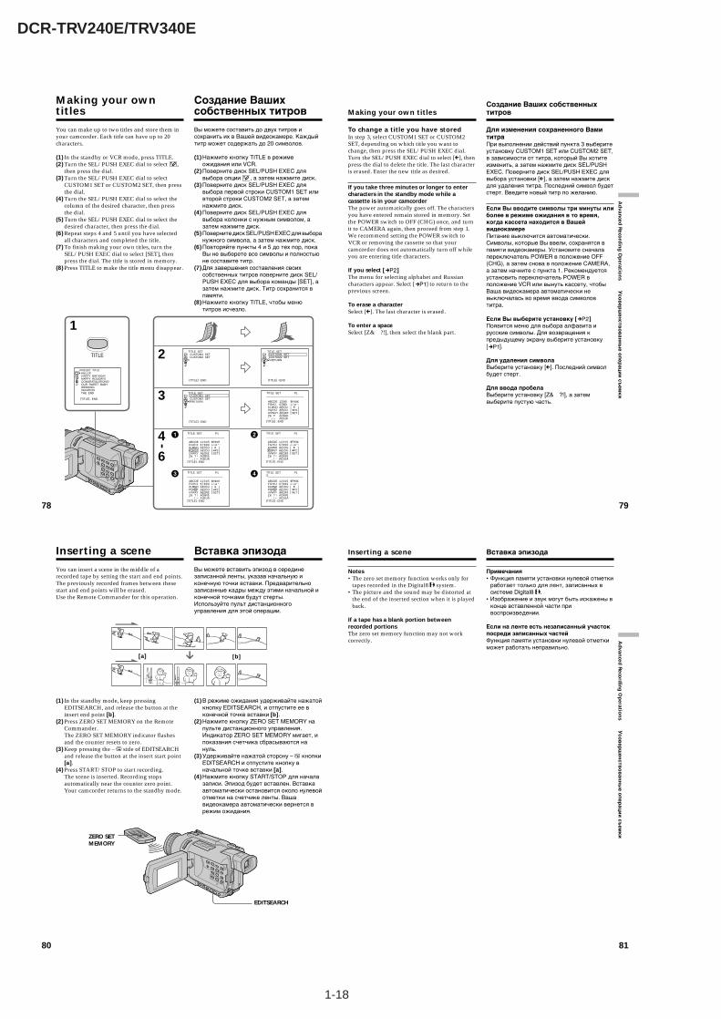
1-18
DCR-TRV240E/TRV340E
80
You can insert a scene in the middle of arecorded tape by setting the start and end points.The previously recorded frames between thesestart and end points will be erased.Use the Remote Commander for this operation.
(1) In the standby mode, keep pressingEDITSEARCH, and release the button at theinsert end point [b].
(2) Press ZERO SET MEMORY on the RemoteCommander.The ZERO SET MEMORY indicator flashesand the counter resets to zero.
(3) Keep pressing the – 7 side of EDITSEARCHand release the button at the insert start point[a].
(4) Press START/STOP to start recording.The scene is inserted. Recording stopsautomatically near the counter zero point.Your camcorder returns to the standby mode.
Inserting a scene
EDITSEARCH
ZERO SETMEMORY
Вы можете вставить эпизод в серединезаписанной ленты, указав начальную иконечную точки вставки. Предварительнозаписанные кадры между этими начальной иконечной точками будут стерты.Используйте пульт дистанционногоуправления для этой операции.
(1) В режиме ожидания удерживайте нажатойкнопку EDITSEARCH, и отпустите ее вконечной точке вставки [b].
(2) Нажмите кнопку ZERO SET MEMORY напульте дистанционного управления.Индикатор ZERO SET MEMORY мигает, ипоказания счетчика сбрасываются нануль.
(3) Удерживайте нажатой сторону – 7 кнопкиEDITSEARCH и отпустите кнопку вначальной точке вставки [a].
(4) Нажмите кнопку START/STOP для началазаписи. Эпизод будет вставлен. Вставкаавтоматически остановится около нулевойотметки на счетчике ленты. Вашавидеокамера автоматически вернется врежим ожидания.
Вставка эпизода
[a] [b]
81
Ad
vanced
Reco
rdin
g O
peratio
ns У
со
ве
рш
ен
ств
ов
ан
ны
е о
пе
ра
ци
и с
ъе
мк
и
Inserting a scene
Notes•The zero set memory function works only for
tapes recorded in the Digital8 system.•The picture and the sound may be distorted at
the end of the inserted section when it is playedback.
If a tape has a blank portion betweenrecorded portionsThe zero set memory function may not workcorrectly.
Вставка эпизода
Примечания•Функция памяти установки нулевой отметки
работает только для лент, записанных всистеме Digital8 .
•Изображение и звук могут быть искажены вконце вставленной части привоспроизведении.
Если на ленте есть незаписанный участокпосреди записанных частейФункция памяти установки нулевой отметкиможет работать неправильно.
78
Making your owntitles
You can make up to two titles and store them inyour camcorder. Each title can have up to 20characters.
(1) In the standby or VCR mode, press TITLE.(2) Turn the SEL/PUSH EXEC dial to select ,
then press the dial.(3) Turn the SEL/PUSH EXEC dial to select
CUSTOM1 SET or CUSTOM2 SET, then pressthe dial.
(4) Turn the SEL/PUSH EXEC dial to select thecolumn of the desired character, then pressthe dial.
(5) Turn the SEL/PUSH EXEC dial to select thedesired character, then press the dial.
(6) Repeat steps 4 and 5 until you have selectedall characters and completed the title.
(7) To finish making your own titles, turn theSEL/PUSH EXEC dial to select [SET], thenpress the dial. The title is stored in memory.
(8) Press TITLE to make the title menu disappear.
1
2
3
4
6
-
TITLE
PRESET TITLE HELLO! HAPPY BIRTHDAY HAPPY HOLIDAYS CONGRATULATIONS! OUR SWEET BABY WEDDING VACATION THE END [TITLE] : END
TITLE SET CUSTOM1 SET CUSTOM2 SET
[TITLE] : END
TITLE SET CUSTOM1 SET CUSTOM2 SET RETURN
[TITLE] : END
TITLE SET CUSTOM1 SET CUSTOM2 SET RETURN
[TITLE] : END
TITLE SET_ _ _ _ _ _ _ _ _ _ _ _ _ _ _ _ _ _ _ _ ABCDE FGHIJ KLMNO PQRST UVWXY Z& ?! ’ . , / – [TITLE] : END
1234567890ÀÈÌÒÙÁÉÍÓÚÂÊÔÆŒÃÕÑçßÄÏÖÜÅ
P1
$F¥DM£¿ i ø ” :[ C ][ cP2 ][ SET ]
TITLE SET_ _ _ _ _ _ _ _ _ _ _ _ _ _ _ _ _ _ _ _ ABCDE FGHIJ KLMNO PQRST UVWXY Z& ? ! ’ . , / –[TITLE] : END
1234567890ÀÈÌÒÙÁÉÍÓÚÂÊÔÆŒÃÕÑçßÄÏÖÜÅ
P1
$F¥DM£¿ i ø ” :[ C ][ cP2 ][ SET ]
TITLE SET_ _ _ _ _ _ _ _ _ _ _ _ _ _ _ _ _ _ _ _ ABCDE FGHIJ KLMNO PQRST UVWXY Z& ? ! ’ . , / –[TITLE] : END
1234567890ÀÈÌÒÙÁÉÍÓÚÂÊÔÆŒÃÕÑçßÄÏÖÜÅ
P1
$F¥DM£¿ i ø ” :[ C ][ cP2 ][ SET ]
TITLE SET_ _ _ _ _ _ _ _ _ _ _ _ _ _ _ _ _ _ _ ABCDE FGHIJ KLMNO PQRST UVWXY Z& ? ! ’ . , / –[TITLE] : END
1234567890ÀÈÌÒÙÁÉÍÓÚÂÊÔÆŒÃÕÑçßÄÏÖÜÅ
P1
$F¥DM£¿ i ø ” :[ C ][ cP2 ][ SET ]
TITLE SETS_ _ _ _ _ _ _ _ _ _ _ _ _ _ _ _ _ _ _ ABCDE FGHIJ KLMNO PQRST UVWXY Z& ? ! ’ . , / –[TITLE] : END
1234567890ÀÈÌÒÙÁÉÍÓÚÂÊÔÆŒÃÕÑçßÄÏÖÜÅ
P1
$F¥DM£¿ i ø ” :[ C ][ cP2 ][ SET ]
Создание Вашихсобственных титров
Вы можете составить до двух титров исохранить их в Вашей видеокамере. Каждыйтитр может содержать до 20 символов.
(1) Нажмите кнопку TITLE в режимеожидания или VCR.
(2) Поверните диск SEL/PUSH EXEC длявыбора опции , а затем нажмите диск.
(3) Поверните диск SEL/PUSH EXEC длявыбора первой строки CUSTOM1 SET иливторой строки CUSTOM2 SET, а затемнажмите диск.
(4) Поверните диск SEL/PUSH EXEC длявыбора колонки с нужным символом, азатем нажмите диск.
(5) Поверните диск SEL/PUSH EXEC для выборанужного символа, а затем нажмите диск.
(6) Повторяйте пункты 4 и 5 до тех пор, покаВы не выберете все символы и полностьюне составите титр.
(7) Для завершения составления своихсобственных титров поверните диск SEL/PUSH EXEC для выбора команды [SET], азатем нажмите диск. Титр сохранится впамяти.
(8) Нажмите кнопку TITLE, чтобы менютитров исчезло.
79
Ad
vanced
Reco
rdin
g O
peratio
ns У
сов
ерш
енств
ов
анн
ые о
пер
аци
и съ
емк
и
To change a title you have storedIn step 3, select CUSTOM1 SET or CUSTOM2SET, depending on which title you want tochange, then press the SEL/PUSH EXEC dial.Turn the SEL/PUSH EXEC dial to select [C], thenpress the dial to delete the title. The last characteris erased. Enter the new title as desired.
If you take three minutes or longer to entercharacters in the standby mode while acassette is in your camcorderThe power automatically goes off. The charactersyou have entered remain stored in memory. Setthe POWER switch to OFF (CHG) once, and turnit to CAMERA again, then proceed from step 1.We recommend setting the POWER switch toVCR or removing the cassette so that yourcamcorder does not automatically turn off whileyou are entering title characters.
If you select [ ]The menu for selecting alphabet and Russiancharacters appear. Select [ ] to return to theprevious screen.
To erase a characterSelect [C]. The last character is erased.
To enter a spaceSelect [Z& ?!], then select the blank part.
Making your own titles
Для изменения сохраненного ВамититраПри выполнении действий пункта 3 выберитеустановку CUSTOM1 SET или CUSTOM2 SET,в зависимости от титра, который Вы хотитеизменить, а затем нажмите диск SEL/PUSHEXEC. Поверните диск SEL/PUSH EXEC длявыбора установки [C], а затем нажмите дискдля удаления титра. Последний символ будетстерт. Введите новый титр по желанию.
Если Вы вводите символы три минуты илиболее в режиме ожидания в то время,когда кассета находится в ВашейвидеокамереПитание выключится автоматически.Символы, которые Вы ввели, сохранятся впамяти видеокамеры. Установите сначалапереключатель POWER в положение OFF(CHG), а затем снова в положение CAMERA,а затем начните с пункта 1. Рекомендуетсяустановить переключатель POWER вположение VCR или вынуть кассету, чтобыВаша видеокамера автоматически невыключалась во время ввода символовтитра.
Если Вы выберите установку [ ]Появится меню для выбора алфавита ирусские символы. Для возвращения кпредыдущему экрану выберите установку[ ].
Для удаления символаВыберите установку [C]. Последний символбудет стерт.
Для ввода пробелаВыберите установку [Z& ?!], а затемвыберите пустую часть.
Создание Ваших собственныхтитров
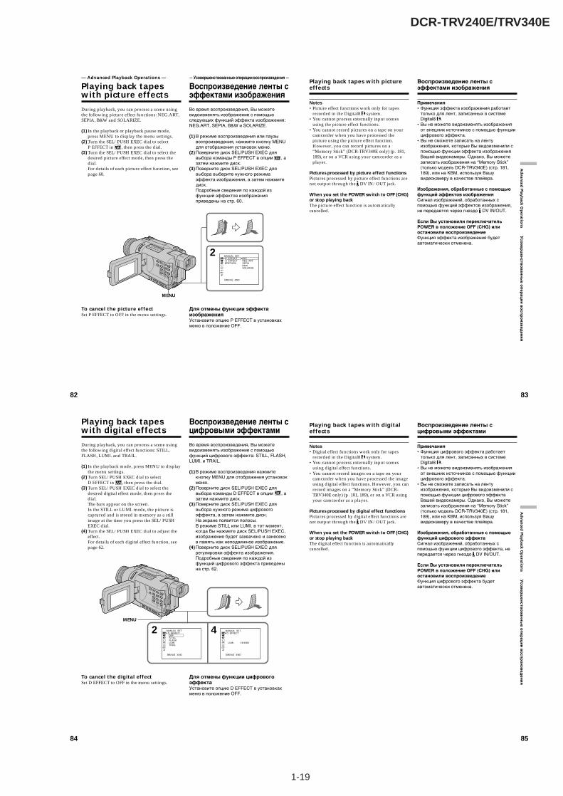
1-19
DCR-TRV240E/TRV340E
82
During playback, you can process a scene usingthe following picture effect functions: NEG.ART,SEPIA, B&W and SOLARIZE.
(1) In the playback or playback pause mode,press MENU to display the menu settings.
(2) Turn the SEL/PUSH EXEC dial to selectP EFFECT in , then press the dial.
(3) Turn the SEL/PUSH EXEC dial to select thedesired picture effect mode, then press thedial.For details of each picture effect function, seepage 60.
To cancel the picture effectSet P EFFECT to OFF in the menu settings.
— Advanced Playback Operations —
Playing back tapeswith picture effects
Во время воспроизведения, Вы можетевидоизменять изображение с помощьюследующих функций эффекта изображения:NEG.ART, SEPIA, B&W и SOLARIZE.
(1) В режиме воспроизведения или паузывоспроизведения, нажмите кнопку MENUдля отображения установок меню.
(2) Поверните диск SEL/PUSH EXEC длявыбора команды P EFFECT в опции , азатем нажмите диск.
(3) Поверните диск SEL/PUSH EXEC длявыбора выберите нужного режимаэффекта изображения, а затем нажмитедиск.Подробные сведения по каждой изфункций эффектов изображенияприведены на стр. 60.
Для отмены функции эффектаизображенияУстановите опцию P EFFECT в установкахменю в положение OFF.
— Усовершенствованные операции воспроизведения —
Воспроизведение ленты сэффектами изображения
2 MANUAL SET P EFFECT D EFFECT RETURN
[MENU] : END
OFFNEG. ARTSEPIAB&WSOLARIZE
MENU
83
Ad
vanced
Playback O
peratio
ns У
со
ве
рш
ен
ств
ов
ан
ны
е о
пе
ра
ци
и в
ос
пр
ои
зве
де
ни
я
Notes•Picture effect functions work only for tapes
recorded in the Digital8 system.•You cannot process externally input scenes
using the picture effect functions.•You cannot record pictures on a tape on your
camcorder when you have processed thepicture using the picture effect function.However, you can record pictures on a“Memory Stick” (DCR-TRV340E only) (p. 181,189), or on a VCR using your camcorder as aplayer.
Pictures processed by picture effect functionsPictures processed by picture effect functions arenot output through the DV IN/OUT jack.
When you set the POWER switch to OFF (CHG)or stop playing backThe picture effect function is automaticallycancelled.
Playing back tapes with pictureeffects
Примечания•Функция эффекта изображения работает
только для лент, записанных в системеDigital8 .
•Вы не можете видоизменять изображенияот внешних источников с помощью функциицифрового эффекта.
•Вы не сможете записать на лентуизображения, которые Вы видоизменили спомощью функции эффекта изображенияВашей видеокамеры. Однако, Вы можетезаписать изображения на “Memory Stick”(только модель DCR-TRV340E) (стр. 181,189), или на КВМ, используя Вашувидеокамеру в качестве плейера.
Изображения, обработанные с помощьюфункций эффектов изображенияСигнал изображений, обработанных спомощью функций эффектов изображения,не передается через гнездо DV IN/OUT.
Если Вы установили переключательPOWER в положение OFF (CHG) илиостановили воспроизведениеФункция эффекта изображения будетавтоматически отменена.
Воспроизведение ленты сэффектами изображения
84
During playback, you can process a scene usingthe following digital effect functions: STILL,FLASH, LUMI. and TRAIL.
(1) In the playback mode, press MENU to displaythe menu settings.
(2) Turn SEL/PUSH EXEC dial to selectD EFFECT in , then press the dial.
(3) Turn SEL/PUSH EXEC dial to select thedesired digital effect mode, then press thedial.The bars appear on the screen.In the STILL or LUMI. mode, the picture iscaptured and is stored in memory as a stillimage at the time you press the SEL/PUSHEXEC dial.
(4) Turn the SEL/PUSH EXEC dial to adjust theeffect.For details of each digital effect function, seepage 62.
To cancel the digital effectSet D EFFECT to OFF in the menu settings.
Playing back tapeswith digital effects
Во время воспроизведения, Вы можетевидоизменять изображение с помощьюфункций цифрового эффекта: STILL, FLASH,LUMI. и TRAIL.
(1)В режиме воспроизведения нажмитекнопку MENU для отображения установокменю.
(2)Поверните диск SEL/PUSH EXEC длявыбора команды D EFFECT в опции , азатем нажмите диск.
(3)Поверните диск SEL/PUSH EXEC длявыбора нужного режима цифровогоэффекта, а затем нажмите диск.На экране появятся полосы.В режиме STILL или LUMI. в тот момент,когда Вы нажмете диск SEL/PUSH EXEС,изображение будет захвачено и занесенов память как неподвижное изображение.
(4)Поверните диск SEL/PUSH EXEС длярегулировки эффекта изображения.Подробные сведения по каждой изфункций цифрового эффекта приведенына стр. 62.
Для отмены функции цифровогоэффектаУстановите опцию D EFFECT в установкахменю в положение OFF.
Воспроизведение ленты сцифровыми эффектами
2 4MANUAL SET D EFFECT OFF ST ILL FLASH LUMI. TRAIL
[MENU] : END
MANUAL SET D EFFECT
LUMI.
[MENU] : END
I I I I I I I I ¥ ¥ ¥ ¥ ¥ ¥ ¥ ¥
MENU
85
Ad
vanced
Playback O
peratio
ns У
со
ве
рш
ен
ств
ов
ан
ны
е о
пе
ра
ци
и в
ос
пр
ои
зве
де
ни
я
Playing back tapes with digitaleffects
Notes•Digital effect functions work only for tapes
recorded in the Digital8 system.•You cannot process externally input scenes
using digital effect functions.•You cannot record images on a tape on your
camcorder when you have processed the imageusing digital effect functions. However, you canrecord images on a “Memory Stick” (DCR-TRV340E only) (p. 181, 189), or on a VCR usingyour camcorder as a player.
Pictures processed by digital effect functionsPictures processed by digital effect functions arenot output through the DV IN/OUT jack.
When you set the POWER switch to OFF (CHG)or stop playing backThe digital effect function is automaticallycancelled.
Воспроизведение ленты сцифровыми эффектами
Примечания•Функция цифрового эффекта работает
только для лент, записанных в системеDigital8 .
•Вы не можете видоизменять изображенияот внешних источников с помощью функциицифрового эффекта.
•Вы не сможете записать на лентуизображения, которые Вы видоизменили спомощью функции цифрового эффектаВашей видеокамеры. Однако, Вы можетезаписать изображения на “Memory Stick”(только модель DCR-TRV340E) (стр. 181,189), или на КВМ, используя Вашувидеокамеру в качестве плейера.
Изображения, обработанные с помощьюфункций цифрового эффектаСигнал изображений, обработанных спомощью функции цифрового эффекта, непередается через гнездо DV IN/OUT.
Если Вы установили переключательPOWER в положение OFF (CHG) илиостановили воспроизведениеФункция цифрового эффекта будетавтоматически отменена.
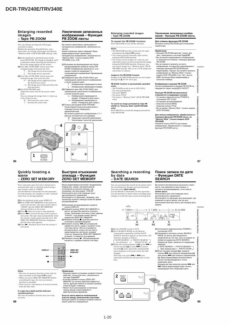
1-20
DCR-TRV240E/TRV340E
88
Your camcorder goes forward or backward toautomatically stop at a desired scene having atape counter value of “0:00:00”.Use the Remote Commander for this operation.Use this function, for example, to view a desiredscene later on during playback.
(1) In the playback mode, press DISPLAY.(2) Press ZERO SET MEMORY at the point you
want to locate later. The tape counter shows“0:00:00” and the ZERO SET MEMORYindicator flashes on the screen.
(3) Press x when you want to stop playback.(4) Press m to rewind the tape to the counter’s
zero point. The tape stops automatically whenthe counter reaches approximately zero. TheZERO SET MEMORY indicator disappears,and the time code appears.
(5) Press N. Playback starts from the counter’szero point.
Notes•The zero set memory function works only for
tapes recorded in the Digital8 system.•When you press ZERO SET MEMORY before
rewinding the tape, the zero set memoryfunction is cancelled.
•There may be a discrepancy of several secondsfrom the time code.
If a tape has a blank portion betweenrecorded portionsThe zero set memory function may not workcorrectly.
Quickly locating ascene– ZERO SET MEMORY
Ваша видеокамера выполняет продвижениевперед или назад с автоматическойостановкой на нужном эпизоде, гдепоказание счетчика равно “0:00:00”.Используйте для этой операции пультдистанционного управления.Используйте эту функцию, например, дляпросмотра нужного эпизода позже во времявоспроизведения.
(1)В режиме воспроизведения нажмитекнопку DISPLAY.
(2)Нажмите кнопку ZERO SET MEMORY вместе, которое Вы захотите отыскатьпозже. Показание счетчика станет равным“0:00:00”, и на экране начнет мигатьиндикатор ZERO SET MEMORY.
(3)Нажмите кнопку x, если Вы захотитеостановить воспроизведение.
(4)Нажмите кнопку m для ускореннойперемотки ленты назад к нулевой точкесчетчика ленты. Лента остановитсяавтоматически, когда счетчик лентыориентировочно достигнет нулевойотметки. Индикатор ZERO SET MEMORYисчезнет, и появится код времени.
(5)Нажмите кнопку N. Воспроизведениеначнется с нулевой отметки счетчика.
Примечания•Функция памяти установки нулевой отметки
работает только для лент, записанных всистеме Digital8 .
•Если Вы нажмете кнопку ZERO SETMEMORY до начала обратной перемоткиленты, функция памяти установки нулевойотметки будет отменена.
•Может быть расхождение в несколькосекунд между кодом времени идействительным временем.
Если на ленте имеется незаписанныйучасток между записанными участкамиФункция памяти установки нулевой отметкиможет работать неправильно.
Быстрое отысканиеэпизода – ФункцияZERO SET MEMORY
DISPLAY ZERO SETMEMORY
Nm
x
89
Ad
vanced
Playback O
peratio
ns У
со
ве
рш
ен
ств
ов
ан
ны
е о
пе
ра
ци
и в
ос
пр
ои
зве
де
ни
я
3
2 SEARCHMODE DATE 00
SEARCH
DATE 01SEARCH
You can automatically search for the point wherethe recording date changes and start playbackfrom that point (date search).Use the Remote Commander for this operation.Use this function to check where recording dateschange or to edit the tape at each recording date.
(1) Set the POWER switch to VCR.(2) Press SEARCH MODE on the Remote
Commander repeatedly until the DATESEARCH indicator appears on the screen. Theindicator changes as follows:
DATE SEARCH t PHOTO SEARCH (no indicator) T PHOTO SCAN
(3) When the current position is [b], press . tosearch towards [a] or press > to searchtowards [c]. Your camcorder automaticallystarts playback at the point where the datechanges.Each time you press . or > yourcamcorder searches for the previous or nextdate.
Searching a recordingby date– DATE SEARCH
Вы можете автоматически выполнять поискместа, где изменяется дата записи, иначинать воспроизведение с этого места(поиск даты).Используйте для этой операции пультдистанционного управления.Используйте эту функцию для выяснения, гдеизменяются даты записи, или же длявыполнения монтажа ленты для каждой датызаписи.
(1) Установите переключатель POWER вположение VCR.
(2) Нажимайте повторно кнопку SEARCHMODE на пульте дистанционногоуправления до тех пор, пока на экране непоявится индикатор DATE SEARCH.Индикатор будет изменяться следующимобразом:
DATE SEARCH t PHOTO SEARCH (Без индикатора) T PHOTO SCAN
(3) Если текущая позиция [b], нажмитекнопку . для поиска в направлении [a]или кнопку > для поиска в направлении[c]. Ваша видеокамера автоматическиначнет воспроизведение в точкеизменения даты.Каждый раз при нажатии кнопки . или>, Ваша видеокамера будет искатьпредыдущую или следующую дату.
Поиск записи по дате– Функция DATESEARCH
[a] [b] [c]
5 7 20024 7 2002 31 12 2002
86
You can enlarge moving and still imagesrecorded on tapes.Besides the operation described here, yourcamcorder can enlarge still images recorded on“Memory Stick”s (DCR-TRV340E only) (p. 218).
(1) In the playback or playback pause mode,press PB ZOOM. The image is enlarged, and Rr indicators which showing the direction tomove the image appear on the screen.
(2) Turn SEL/PUSH EXEC dial to move theenlarged image, then press the dial.
R : The image moves downwards.r : The image moves upwards.
(3) Turn SEL/PUSH EXEC dial to move theenlarged image, then press the dial.
T : The image moves rightward (Turnthe dial downwards.)
t : The image moves leftward (Turn thedial upwards.)
(4) For DCR-TRV340E only:Adjust the zoom ratio by the power zoomlever.You can enlarge the image from 1.1 times upto five times its size.
W : Decreases the zoom ratio.T : Increase the zoom ratio.
Enlarging recordedimages– Tape PB ZOOM
3
4
2 PB ZOOM × 5.0
[EXEC] : T t
PB ZOOM × 5.0
[EXEC] : r R
1PB ZOOM
Вы можете увеличивать движущиеся инеподвижные изображения, записанные налентах.Кроме описанных здесь операций, Вашавидеокамера может увеличиватьнеподвижные изображения, записанные на“Memory Stick” (только модель DCR-TRV340E) (стр. 218).
(1) В режиме воспроизведения или паузывоспроизведения нажмите кнопку PBZOOM. Изображение увеличится, а наэкране появится индикация R r,показывающая направление перемещенияизображения.
(2) Поверните диск SEL/PUSH EXEC дляперемещения увеличенного изображения,а затем нажмите диск.
R : Изображение перемещается вниз.r : Изображение перемещается вверх.
(3) Поверните диск SEL/PUSH EXEC дляперемещения увеличенного изображения,а затем нажмите диск.
T : Изображения перемещаетсявправо. (Поверните диск вниз.)
t : Изображение перемещаетсявлево. (Поверните диск вверх.)
(4) Только для модели DCR-TRV340E:Отрегулируйте масштаб увеличения спомощью рычага приводноговариообъектива.Вы можете увеличить изображение от 1,1раза до пятикратного его размера.
W : Уменьшает масштаб увеличения.T : Увеличивает масштаб увеличения.
Увеличение записанныхизображений – ФункцияPB ZOOM ленты
87
Ad
vanced
Playback O
peratio
ns У
сов
ерш
енств
ов
анн
ые о
пер
аци
и в
осп
ро
изв
еден
ия
Enlarging recorded images– Tape PB ZOOM
To cancel the PB ZOOM functionPress PB ZOOM to turn off the indicator.
Notes•The PB ZOOM function works only for tapes
recorded in the Digital8 system.•You cannot process externally input scenes
using the PB ZOOM function.•You cannot record images on a tape on your
camcorder when you have processed the imageusing the PB ZOOM function. However, youcan record images on a “Memory Stick” (DCR-TRV340E only) (p. 181), or on a VCR using yourcamcorder as a player.
Images in the PB ZOOM functionImages in the PB ZOOM function are not outputthrough the DV IN/OUT jack.
PB ZOOM function is automatically cancelledwhen:– The POWER switch is set to OFF (CHG)– You stop playing back– You press MENU– You press TITLE– You insert a “Memory Stick” (DCR-TRV340E
only)
To record an image processed by Tape PBZOOM on "Memory Stick"s (DCR-TRV340Eonly)Press PHOTO to record the image processed byTape PB ZOOM.
Увеличение записанных изобра-жений – Функция PB ZOOM ленты
Для отмены функции PB ZOOMНажмите кнопку PB ZOOM для отключенияиндикатора.
Примечания•Функция PB ZOOM работает только для
лент, записанных в системе Digital8 .•Вы не можете видоизменять изображения
от внешних источников с помощью функцииPB ZOOM.
•Вы не сможете записать на лентуизображения, которые Вы видоизменили спомощью функции PB ZOOM Вашейвидеокамеры. Однако, Вы можете записатьизображения на “Memory Stick” (толькомодель DCR-TRV340E) (стр. 181), или наКВМ, используя Вашу видеокамеру вкачестве плейера.
Изображения в режиме PB ZOOMСигнал изображения в режиме PB ZOOM непередается через гнездо DV IN/OUT.
Функция PB ZOOM автоматическиотменяется в следующих случаях:– Установка переключателя POWER в
положение OFF (CHG)– Остановка воспроизведения– Нажатие кнопки MENU– Нажатие кнопки TITLE– Вы вставили “Memory Stick” (только модель
DCR-TRV340E)
Для записи изображения, обработанного спомощью функции PB ZOOM ленты, на“Memory Stick” (только модель DCR-TRV340E)Нажмите кнопку PHOTO для записиизображения, обработанного с помощьюфункции PB ZOOM ленты.
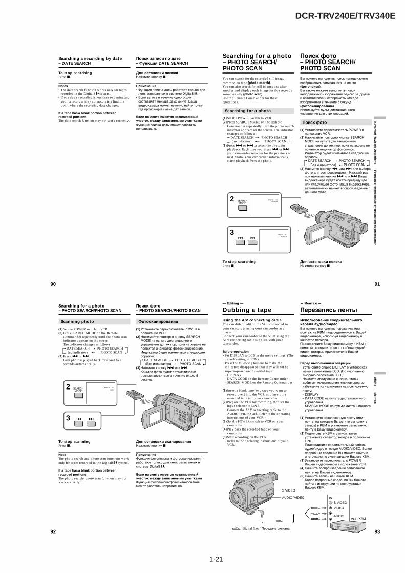
1-21
DCR-TRV240E/TRV340E
90
Searching a recording by date– DATE SEARCH
To stop searchingPress x.
Notes•The date search function works only for tapes
recorded in the Digital8 system.•If one day’s recording is less than two minutes,
your camcorder may not accurately find thepoint where the recording date changes.
If a tape has a blank portion betweenrecorded portionsThe date search function may not work correctly.
Поиск записи по дате– Функция DATE SEARCH
Для остановки поискаНажмите кнопку x.
Примечания•Функция поиска даты работает только для
лент, записанных в системе Digital8 .•Если запись в течение одного дня
составляет меньше двух минут, Вашавидеокамера может неточно найти точку,где происходит смена дат записи.
Если на ленте имеется незаписанныйучасток между записанными участкамиФункция поиска даты может работатьнеправильно.
91
Ad
vanced
Playback O
peratio
ns У
со
ве
рш
ен
ств
ов
ан
ны
е о
пе
ра
ци
и в
ос
пр
ои
зве
де
ни
я
You can search for the recorded still imagerecorded on tape (photo search).You can also search for still images one afteranother and display each image for five secondsautomatically (photo scan).Use the Remote Commander for theseoperations.
Searching for a photo
(1) Set the POWER switch to VCR.(2) Press SEARCH MODE on the Remote
Commander repeatedly until the photo searchindicator appears on the screen. The indicatorchanges as follows:
DATE SEARCH t PHOTO SEARCH (no indicator) T PHOTO SCAN
(3) Press . or > to select the photo forplayback. Each time you press . or >your camcorder searches for the previous ornext photo. Your camcorder automaticallystarts playback from the photo.
To stop searchingPress x.
Searching for a photo– PHOTO SEARCH/PHOTO SCAN
Вы можете выполнять поиск неподвижногоизображения, записанного на ленте(фотопоиск).Вы также можете выполнять поискнеподвижных изображений одного за другими автоматически отображать каждоеизображение в течение 5 секунд(фотосканирование).Используйте пульт дистанционногоуправления для этих операций.
Поиск фото
(1) Установите переключатель POWER вположение VCR.
(2) Нажимайте повторно кнопку SEARCHMODE на пульте дистанционногоуправления до тех пор, пока на экране непоявится индикатор фотопоиск.Индикатор будет изменяться следующимобразом:
DATE SEARCH t PHOTO SEARCH (Без индикатора) T PHOTO SCAN
(3) Нажмите кнопку . или > для выборафото для воспроизведения. Каждый разпри нажатии кнопки . или > Вашавидеокамера будет искать предыдущееили следующее фото. Ваша видеокамераавтоматически начнет воспроизведение сданного фото.
Для остановки поискаНажмите кнопку x.
Поиск фото– PHOTO SEARCH/PHOTO SCAN
3 PHOTO 01SEARCH
2 SEARCHMODE
PHOTO 00SEARCH
92
Scanning photo
(1) Set the POWER switch to VCR.(2) Press SEARCH MODE on the Remote
Commander repeatedly until the photo scanindicator appears on the screen.The indicator changes as follows:
DATE SEARCH t PHOTO SEARCH (no indicator) T PHOTO SCAN
(3) Press . or >.Each photo is played back for about fiveseconds automatically.
To stop scanningPress x.
NoteThe photo search and photo scan functions workonly for tapes recorded in the Digital8 system.
If a tape has a blank portion betweenrecorded portionsThe photo search/photo scan function may notwork correctly.
Searching for a photo– PHOTO SEARCH/PHOTO SCAN
Фотосканирование
(1) Установите переключатель POWER вположение VCR.
(2) Нажимайте повторно кнопку SEARCHMODE на пульте дистанционногоуправления до тех пор, пока на экране непоявится индикатор фотосканирование.Индикатор будет изменяться следующимобразом:
DATE SEARCH t PHOTO SEARCH (Без индикатора) T PHOTO SCAN
(3) Нажмите кнопку . или >.Каждое фото будет автоматическивоспроизводиться в течение около 5секунд.
Для остановки сканированияНажмите кнопку x.
ПримечаниеФункции фотопоиска и фотосканированияработают только для лент, записанных всистеме Digital8 .
Если на ленте имеется незаписанныйучасток между записанными участкамиФункция фотопоиска/фотосканированияможет работать неправильно.
Поиск фото– PHOTO SEARCH/PHOTO SCAN
3
2 SEARCHMODE
PHOTO 00SCAN
93
Editin
g М
он
таж
— Editing —
Dubbing a tape
Using the A/V connecting cableYou can dub or edit on the VCR connected toyour camcorder using your camcorder as aplayer.Connect your camcorder to the VCR using theA/V connecting cable supplied with yourcamcorder.
Before operation•Set DISPLAY to LCD in the menu settings. (The
default setting is LCD.)•Press the following buttons to make the
indicators disappear so that they will not besuperimposed on the edited tape:– DISPLAY– DATA CODE on the Remote Commander– SEARCH MODE on the Remote Commander
(1) Insert a blank tape (or a tape you want torecord over) into the VCR, and insert therecorded tape into your camcorder.
(2) Prepare the VCR for recording, then set theinput selector to LINE.Connect the A/V connecting cable to theAUDIO/VIDEO jack. Refer to the operatinginstructions of your VCR.
(3) Set the POWER switch to VCR on yourcamcorder.
(4) Play back the recorded tape on yourcamcorder.
(5) Start recording on the VCR.Refer to the operating instructions of yourVCR.
AUDIO
VIDEO
S VIDEO
IN
S VIDEO
AUDIO / VIDEO
: Signal flow/Передача сигнала
VCR/КВМ
— Монтаж —
Перезапись ленты
Использование соединительногокабеля аудио/видеоВы можете выполнять перезапись илимонтаж на КВМ, подсоединенном к Вашейвидеокамере, используя видеокамеру вкачестве плейера.Подсоедините Вашу видеокамеру к КВМ спомощью соединительного кабеля аудио/видео, который прилагается к Вашейвидеокамере.
Перед выполнением операции•Установите опцию DISPLAY в установках
меню в положение LCD. (По умолчаниювыбрано положение LCD.)
•Нажмите следующие кнопки, чтобыдобиться исчезновения индикаторов воизбежание их наложения на монтируемуюленту:– DISPLAY– DATA CODE на пульте дистанционного
управления– SEARCH MODE на пульте дистанционного
управления
(1) Установите незаписанную ленту (илиленту, на которую Вы хотите выполнитьзапись) в КВМ и установите записаннуюленту в Вашу видеокамеру.
(2) Подготовьте КВМ к записи, затемустановите селектор входов в положениеLINE.Подсоедините соединительный кабельаудио/видео в гнездо AUDIO/VIDEO. Болееподробные сведения Вы можете найти винструкции по эксплуатации Вашего КВМ.
(3) Установите переключатель POWERВашей видеокамеры в положение VCR.
(4) Начните воспроизведение записаннойленты на Вашей видеокамере.
(5) Начните запись на Вашем КВМ.Более подробные сведения Вы можетенайти в инструкции по эксплуатацииВашего КВМ.

1-22
DCR-TRV240E/TRV340E
96
Dubbing a tape
Note on tapes that are not recorded in theDigital8 systemThe picture may fluctuate. This is not amalfunction.
During playback of tapes recorded in the Hi8/standard 8 systemDigital signals are output as the image signalsfrom the DV IN/OUT jack.
You can connect one VCR only using the i.LINKcable (DV connecting cable)See page 256 for more information about i.LINK.
Pictures processed by picture effects, digitaleffects or the PB ZOOM functionPictures processed by picture effects, digitaleffects or the PB ZOOM function are not outputthrough the DV IN/OUT jack.
If you record playback pause picture with the DV IN/OUT jack
The recorded picture becomes rough. Also, whenyou play back the picture using other videoequipment, the picture may jitter.
Перезапись ленты
Примечание по лентам, которые незаписаны в системе Digital8 Изображение может подрагивать. Это неявляется неисправностью.
При воспроизведении лент, записанных всистеме Hi8/standard 8Цифровые сигналы выводятся в качествесигналов изображения из гнезда DV IN/OUT.
Вы можете подсоединить один толькоКВМ с помощью кабеля i.LINK(соединительного кабеля DV)Для получения более подробных сведений окабеле i.LINK обращайтесь к стр. 256.
Изображения, видоизмененныепосредством эффектов изображения,цифровых эффектов или функции PBZOOMИзображения, видоизмененные посредствомэффектов изображения, цифровыхэффектов или функции PB ZOOM невыводятся через гнездо DV IN/OUT.
При записи на паузе воспроизводимогоизображения через гнездо DV IN/OUTЗаписанное изображение будет искаженным.Также, при воспроизведении изображений надругой аппаратуре, изображение можетподрагивать.
97
Editin
g М
он
таж
You can duplicate selected scenes (programmes)for editing onto a tape without operating theVCR.Scenes can be selected by frame. You can set upto 20 programmes.Your camcorder can dub on “Memory Stick”s(DCR-TRV340E only). See page 193 for moreinformation.
Dubbing only desiredscenes – Digital programediting (on tapes)
Unwanted scene/Нежелательныйэпизод
Unwanted scene/Нежелательныйэпизод
Switch the order/Изменить порядок
Вы можете перезаписывать избранныеэпизоды (программы) для монтажа на лентубез использования КВМ.Эпизоды могут выбираться в покадровомрежиме. Вы можете установить до 20программ.Ваша видеокамера может производитьперезапись на “Memory Stick” (только модельDCR-TRV340E). Для получения болееподробных сведений обращайтесь к стр. 193.
Перезапись только нужныхэпизодов – Цифровой монтажпрограммы (на лентах)
94
When you have finished dubbing atapePress x on both your camcorder and the VCR.
You can edit on VCRs that support thefollowing systems:
8 mm, Hi8, VHS, S-VHS, VHSC, S-VHSC, Betamax, miniDV, DV or Digital8
If your VCR is a monaural typeConnect the yellow plug of the A/V connectingcable to the video input jack and the white or thered plug to the audio input jack on the VCR orthe TV. When the white plug is connected, theleft channel audio is output, and when the redplug is connected, the right channel audio isoutput.
If your VCR has an S video jackPictures can be reproduced more faithfully byusing an S video cable (optional).With this connection, you do not need to connectthe yellow (video) plug of the A/V connectingcable.Connect an S video cable (optional) to the S videojacks of both your camcorder and the VCR.
Dubbing a tape
Если Вы закончили перезапись лентыНажмите кнопку x как на видеокамере, так ина КВМ.
Вы можете выполнять монтаж на КВМ,которые поддерживают следующиесистемы:
8 мм, Hi8, VHS, S-VHS, VHSC, S-VHSC, Betamax, miniDV, DV или Digital8
Если Ваш КВМ монофонического типаПодсоедините желтый штекерсоединительного кабеля аудио/видео квходному видеогнезду, а белый или красныйштекер к входному аудиогнезду на КВМ илителевизоре. Если подсоединен белыйштекер, то выходным сигналом будет звуклевого канала, а если подсоединен красныйштекер, то выходным сигналом будет звукправого канала.
Если в Вашем КВМ имеется гнездо S видеоИзображения могут быть воспроизведеныболее высококачественно при использованиикабеля S видео (приобретается отдельно).При таком подсоединении Вам не нужноподсоединять желтый (видео) штекерсоединительного кабеля аудио/видео.Подсоедините кабель S видео(приобретается отдельно) к гнездам S видеона Вашей видеокамере и КВМ.
Перезапись ленты
95
Editin
g М
он
таж
Using the i.LINK cable (DV connectingcable)Simply connect the i.LINK cable (DV connectingcable) (optional) to DV IN/OUT on yourcamcorder and to DV IN/OUT on the DVproducts. With a digital-to-digital connection,video and audio signals are transmitted in digitalform for high-quality editing. You cannot dubthe screen indicators.
(1) Insert a blank tape (or a tape you want torecord over) into the VCR, and insert therecorded tape into your camcorder.
(2) Set the input selector on the VCR to DV IN ifit is available. Refer to the operatinginstructions of your VCR.
(3) Set the POWER switch to VCR on yourcamcorder.
(4) Play back the recorded tape on yourcamcorder.
(5) Start recording on the VCR.Refer to the operating instructions of yourVCR.
When you have finished dubbing atapePress x on both your camcorder and the VCR.
Dubbing a tape
Использование кабеля i.LINK(Соединительный кабель цифровоговидеосигнала DV)Просто подсоедините кабель i.LINK(соединительный кабель цифровоговидеосигнала DV) (приобретается отдельно)к гнезду DV IN/OUT на Вашей видеокамереи гнезду DV IN/OUT цифровых видеоизделий.При цифро-цифровом соединении видео- иаудиосигналы передаются в цифровомформате для высококачественного монтажа.Вы не можете выполнять перезаписьэкранных индикаторов.
(1) Установите незаписанную ленту (илиленту, на которую хотите выполнитьзапись) в КВМ и установите записаннуюленту в Вашу видеокамеру.
(2) Установите селектор входов на КВМ вположение DV IN при его наличии. Болееподробные сведения Вы можете найти винструкции по эксплуатации Вашего КВМ.
(3) Установите переключатель POWER наВашей видеокамере в положение VCR.
(4) Начните воспроизведение записаннойленты на Вашей видеокамере.
(5) Начните запись на КВМ. Более подробныесведения Вы сможете найти в инструкциипо эксплуатации Вашего КВМ.
Если Вы закончили перезапись лентыНажмите кнопку x как на Вашейвидеокамере, так и на КВМ.
Перезапись ленты
DV
DV IN/OUTDV IN/OUT
: Signal flow/Передача сигнала
(optional)/(приобретается отдельно)
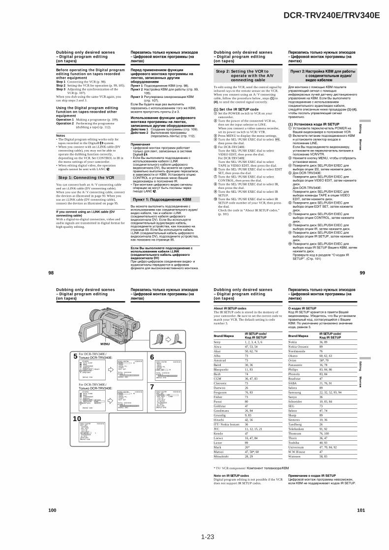
1-23
DCR-TRV240E/TRV340E
98
Dubbing only desired scenes– Digital program editing(on tapes)
Before operating the Digital programediting function on tapes recordedother equipmentStep 1 Connecting the VCR (p. 98).Step 2 Setting the VCR for operation (p. 99, 105).Step 3 Adjusting the synchronization of the
VCR (p. 107).When you dub using the same VCR again, youcan skip steps 2 and 3.
Using the Digital program editingfunction on tapes recorded otherequipmentOperation 1 Making a programme (p. 109).Operation 2 Performing the programme
(dubbing a tape) (p. 112).
Notes•The Digital program editing works only for
tapes recorded in the Digital8 system.•When you connect with an i.LINK cable (DV
connecting cable), you may not be able tooperate the dubbing function correctly,depending on the VCR. Set CONTROL to IR inthe menu settings of your camcorder.
•When editing digital video, the operationsignals cannot be sent with LANC .
Step 1: Connecting the VCR
You can connect both an A/V connecting cableand an i.LINK cable (DV connecting cable).When you use the A/V connecting cable, connectthe devices as illustrated in page 93. When youuse an i.LINK cable (DV connecting cable),connect the devices as illustrated on page 95.
If you connect using an i.LINK cable (DVconnecting cable)With a digital-to-digital connection, video andaudio signals are transmitted in digital format forhigh-quality editing.
Перезапись только нужных эпизодов– Цифровой монтаж программы (налентах)
Перед применением функциицифрового монтажа программы налентах, записанных другимоборудованиемПункт 1 Подсоединение КВМ (стр. 98).Пункт 2 Настройка КВМ для работы (стр. 99,
105).Пункт 3 Регулировка синхронизации КВМ
(стр. 107).Если Вы будете еще раз выполнятьперезапись с использованием того же КВМ,можете пропустить пункты 2 и 3.
Использование функции цифровогомонтажа программы на лентах,записанных другим оборудованиемДействие 1 Создание программы (стр. 109).Действие 2 Выполнение программы
(перезапись ленты) (стр. 112).
Примечания•Цифровой монтаж программ работает
только для лент, записанных в системеDigital8 .
•Если Вы выполняете подсоединение сиспользованием кабеля i.LINK(соединительного кабеля цифровоговидеосигнала DV), Вы можете не суметьправильно выполнить функцию перезаписи,в зависимости от КВМ. Установите опциюCONTROL в установках меню Вашейвидеокамеры в положение IR.
•При монтаже цифрового видео сигналыоперации не могут быть посланы черезгнездо LANC .
Пункт 1: Подсоединение КВМ
Вы можете выполнить подсоединение сиспользованием как соединительного аудио/видео кабеля, так и кабеля i.LINK(соединительного кабеля цифровоговидеосигнала DV). Если Вы используетесоединительный аудио/видео кабель,подсоедините устройства, как показано настранице 93. Если Вы используете кабельi.LINK (соединительный кабель цифровоговидеосигнала DV), подсоедините устройства,как показано на странице 95.
Если Вы выполняете подсоединение сиспользованием кабеля i.LINK(соединительного кабель цифровоговидеосигнала DV)При цифро-цифровом соединении видео- иаудиосигналы передаются в цифровомформате для высококачественного монтажа.
99
Editin
g М
он
таж
Step 2: Setting the VCR tooperate with the A/Vconnecting cable
To edit using the VCR, send the control signal byinfrared rays to the remote sensor on the VCR.When you connect using an A/V connectingcable, follow the procedure below, steps (1) to(4), to send the control signal correctly.
(1) Set the IR SETUP code1 Set the POWER switch to VCR on your
camcorder.2 Turn the power of the connected VCR on,
then set the input selector to LINE.When you connect a video camera recorder,set its power switch to VCR/VTR.
3 Press MENU to display the menu settings.4 Turn the SEL/PUSH EXEC dial to select ,
then press the dial.5 For DCR-TRV240E:
Turn the SEL/PUSH EXEC dial to selectVIDEO EDIT, then press the dial.For DCR-TRV340E:Turn the SEL/PUSH EXEC dial to selectTAPE in VIDEO EDIT, then press the dial.
6 Turn the SEL/PUSH EXEC dial to select EDITSET, then press the dial.
7 Turn the SEL/PUSH EXEC dial to selectCONTROL, then press the dial.
8 Turn the SEL/PUSH EXEC dial to select IR,then press the dial.
9 Turn the SEL/PUSH EXEC dial to select IRSETUP.
0 Turn the SEL/PUSH EXEC dial to select IRSETUP code number of your VCR, then pressthe dial.Check the code in “About IR SETUP codes.”(p. 101)
Dubbing only desired scenes– Digital program editing(on tapes)
Пункт 2: Настройка КВМ для работыс соединительным аудио/видео кабелем
Для монтажа с помощью КВМ пошлитеуправляющий сигнал с помощьюинфракрасных лучей датчику дистанционногоуправления на КВМ. Если Вы выполняетеподсоединение с использованиемсоединительного аудио/видео кабеля,следуйте описанным ниже процедурам (1)-(4),чтобы послать управляющий сигналправильно.
(1) Установка кода IR SETUP1 Установите переключатель POWER на
Вашей видеокамере в положение VCR.2 Включите питание подсоединенного КВМ
и установите селектор входов вположение LINE.Если Вы подсоединяете видеокамеру,установите ее переключатель питания вположение VCR/VTR.
3 Нажмите кнопку MENU, чтобы отобразитьустановки меню.
4 Поверните диск SEL/PUSH EXEC длявыбора опции , затем нажмите диск.
5 Для DCR-TRV240E:Поверните диск SEL/PUSH EXEC длявыбора опции VIDEO EDIT, затем нажмитедиск.Для DCR-TRV340E:Поверните диск SEL/PUSH EXEC длявыбора команды TAPE в опции VIDEOEDIT, затем нажмите диск.
6 Поверните диск SEL/PUSH EXEC длявыбора опции EDIT SET, затем нажмитедиск.
7 Поверните диск SEL/PUSH EXEC длявыбора опции CONTROL, затем нажмитедиск.
8 Поверните диск SEL/PUSH EXEC длявыбора опции IR, затем нажмите диск.
9 Поверните диск SEL/PUSH EXEC длявыбора опции IR SETUP, затем нажмитедиск.
0 Поверните диск SEL/PUSH EXEC длявыбора кода IR SETUP Вашего КВМ, затемнажмите диск.Проверьте код в разделе “О кодах IRSETUP”. (Стр. 101)
Перезапись только нужных эпизодов– Цифровой монтаж программы (налентах)
100
Dubbing only desired scenes– Digital program editing(on tapes)
5
7
6
10
OTHERS DATA CODE BEEP COMMANDER DISPLAY VIDEO EDIT INDICATOR RETURN
READY
[MENU] : END
VIDEO EDIT MARK UNDO ERASE ALL START EDIT SET IR
0:08:55:06
TOTAL 0:00:00:00SCENE 0
[MENU] : END
VIDEO EDIT MARK UNDO ERASE ALL START EDIT SET
1 IN0:08:55:06
TOTAL 0:00:00:00SCENE 0
[MENU] : END
VIDEO EDIT EDIT SET CONTROL ADJ TEST ”CUT–IN” ”CUT–OUT” IR SETUP PAUSEMODE IR TEST RETURN
IRi. LINK
0:08:55:06
[MENU] : END
VIDEO EDIT EDIT SET CONTROL ADJ TEST ”CUT–IN” ”CUT–OUT” IR SETUP PAUSEMODE IR TEST RETURN
3
0:08:55:06
[MENU] : END
OTHERS DATA CODE BEEP COMMANDER DISPLAY VIDEO EDIT INDICATOR RETURN
RETURNTAPEMEMORY
[MENU] : END
VIDEO EDIT MARK UNDO ERASE ALL START EDIT SET
1 IN0:08:55:06
TOTAL 0:00:00:00SCENE 0
[MENU] : END
MENU
For DCR-TRV240E:/Только DCR-TRV240E:
For DCR-TRV340E:/Только DCR-TRV340E:
Перезапись только нужных эпизодов– Цифровой монтаж программы (налентах)
101
Editin
g М
он
таж
IR SETUP code/Brand/Марка Код IR SETUP
Nokia 36, 89Nokia Oceanic 89Nordmende 76Okano 60, 62, 63Orion 58*, 70Panasonic 16, 78Philips 83, 84, 86Phonola 83, 84Roadstar 47SABA 21, 76, 91Salora 89Samsung 22, 32, 52, 93, 94Sanyo 36Schneider 10, 83, 84SEG 73Seleco 47, 74Sharp 89Siemens 10, 36Tandberg 26Telefunken 91, 92Thomson 76, 100Thorn 36, 47Toshiba 40, 93Universum 47, 70, 84, 92W.W.House 47Watoson 58, 83
IR SETUP code/Brand/Марка Код IR SETUP
Sony 1, 2, 3, 4, 5, 6Aiwa 47, 53, 54Akai 50, 62, 74Alba 73Amstrad 73Baird 30, 36Blaupunkt 11, 83Bush 74CGM 36, 47, 83Clatronic 73Daewoo 26Ferguson 76, 83Fisher 73Funai 80Goldstar 47Goodmans 26, 84Grundig 9, 83Hitachi 42, 56ITT/Nokia Instant 36JVC 11, 12, 15, 21Kendo 47Loewe 16, 47, 84Luxor 89Mark 26*Matsui 47, 58*, 60Mitsubishi 28, 29
Dubbing only desired scenes– Digital program editing(on tapes)
Note on IR SETUP codesDigital program editing is not possible if the VCRdoes not support IR SETUP codes.
About IR SETUP codesThe IR SETUP code is stored in the memory ofyour camcorder. Be sure to set the correct code tomatch your VCR. The default setting is codenumber 3.
О кодах IR SETUPКод IR SETUP хранится в памяти Вашейвидеокамеры. Убедитесь, что Вы установилиправильный код, согласующийся с ВашимКВМ. По умолчанию установлено значениекода, равное 3.
Примечание о кодах IR SETUPЦифровой монтаж программы невозможен,если КВМ не поддерживает кодов IR SETUP.
Перезапись только нужных эпизодов– Цифровой монтаж программы (налентах)
* TV/VCR component/Компонент телевизора/КВМ

1-24
DCR-TRV240E/TRV340E
104
(4) Confirming VCR operation1 Insert a recordable tape into the VCR, then set
to recording pause.2 Turn the SEL/PUSH EXEC dial to select IR
TEST, then press the dial.3 Turn the SEL/PUSH EXEC dial to select
EXECUTE, then press the dial.If the VCR starts recording, the setting iscorrect.When recording is finished, the indicatorchanges to COMPLETE.
When the VCR does not operate correctly•After checking the code in “About IR SETUP
codes”, set the IR SETUP or the PAUSEMODEagain.
•Place your camcorder at least 30 cm (12 in.)away from the VCR.
•Refer to the operating instructions of your VCR.
Dubbing only desired scenes– Digital program editing(on tapes)
(4) Подтверждение действия КВМ1 Установите записываемую кассету в КВМ
и установите его на паузу записи.2 Поверните диск SEL/PUSH EXEC для
выбора опции IR TEST, затем нажмитедиск.
3 Поверните диск SEL/PUSH EXEC длявыбора опции EXECUTE, затем нажмитедиск.Если КВМ начал запись, настройкавыполнена правильно.По окончании индикатор изменится наCOMPLETE.
Если КВМ не работает надлежащимобразом•После проверки кода в пункте “О кодах IR
SETUP”, установите опцию IR SETUP илиPAUSEMODE еще раз.
•Поместите Вашу видеокамеру нарасстоянии, по крайней мере, 30 см от КВМ.
•Обращайтесь к руководству поэксплуатации Вашего КВМ.
Перезапись только нужных эпизодов– Цифровой монтаж программы (налентах)
2 3VIDEO EDIT EDIT SET CONTROL ADJ TEST ”CUT–IN” ”CUT–OUT” IR SETUP PAUSEMODE IR TEST RETURN
RETURNEXECUTE
ENGAGEREC PAUSE
0:08:55:06
[MENU] : END
VIDEO EDIT EDIT SET CONTROL ADJ TEST ”CUT–IN” ”CUT–OUT” IR SETUP PAUSEMODE IR TEST RETURN
COMPLETE
0:08:55:06
[MENU] : END
105
Editin
g М
он
таж
Dubbing only desired scenes– Digital program editing(on tapes)
Step 2: Setting the VCR to operatewith the i.LINK cable(DV connecting cable)
When you connect using i.LINK cable (DVconnecting cable) (optional), follow theprocedure below.
(1) Set the POWER switch to VCR on yourcamcorder.
(2) Turn the power of the connected VCR on,then set the input selector to DV input. Whenyou connect a digital video camera recorder,set its power switch to VCR/VTR.
(3) Press MENU to display the menu settings.(4) Turn the SEL/PUSH EXEC dial to select ,
then press the dial.(5) For DCR-TRV240E:
Turn the SEL/PUSH EXEC dial to selectVIDEO EDIT, then press the dial.For DCR-TRV340E:Turn the SEL/PUSH EXEC dial to selectTAPE in VIDEO EDIT, then press the dial.
(6) Turn the SEL/PUSH EXEC dial to select EDITSET, then press the dial.
(7) Turn the SEL/PUSH EXEC dial to selectCONTROL, then press the dial.
(8) Turn the SEL/PUSH EXEC dial to selecti.LINK, then press the dial.
Пункт 2: Настройка КВМ для работы скабелем i.LINK(соединительным кабелемцифрового видеосигнала DV)
Если Вы выполняете подсоединение сиспользованием кабеля i.LINK(соединительного кабеля цифровоговидеосигнала DV) (приобретается отдельно),следуйте описанным ниже процедурам.
(1) Установите переключатель POWER наВашей видеокамере в положение VCR.
(2) Включите питание подсоединенного КВМи установите селектор входов вположение входа цифрового видеосигналаDV. Если Вы подсоединяете цифровуювидеокамеру, установите еепереключатель питания в положение VCR/VTR.
(3) Нажмите кнопку MENU, чтобы отобразитьустановки меню.
(4) Поверните диск SEL/PUSH EXEC длявыбора опции , затем нажмите диск.
(5) Для DCR-TRV240E:Поверните диск SEL/PUSH EXEC длявыбора опции VIDEO EDIT, затем нажмитедиск.Для DCR-TRV340E:Поверните диск SEL/PUSH EXEC длявыбора команды TAPE в опции VIDEOEDIT, затем нажмите диск.
(6) Поверните диск SEL/PUSH EXEC длявыбора опции EDIT SET, затем нажмитедиск.
(7) Поверните диск SEL/PUSH EXEC длявыбора опции CONTROL, затем нажмитедиск.
(8) Поверните диск SEL/PUSH EXEC длявыбора опции i.LINK, затем нажмите диск.
Перезапись только нужных эпизодов– Цифровой монтаж программы (налентах)
102
(2) Setting the modes to cancel therecording pause on the VCR
1 Turn the SEL/PUSH EXEC dial to selectPAUSEMODE, then press the dial.
2 Turn the SEL/PUSH EXEC dial to select themode to cancel recording pause on the VCR,then press the dial.Refer to the operating instructions of yourVCR.
Buttons to cancel recording pause on the VCRThe buttons vary depending on your VCR. Tocancel recording pause:– Select PAUSE if the button to cancel recording
pause is X.– Select REC if the button to cancel recording
pause is z.– Select PB if the button to cancel recording pause
is N.
Dubbing only desired scenes– Digital program editing(on tapes)
(2) Установка режимов для отменыпаузы записи на КВМ
1 Поверните диск SEL/PUSH EXEC длявыбора опции PAUSEMODE, затемнажмите диск.
2 Поверните диск SEL/PUSH EXEC, чтобывыбрать режим отмены паузы записи наКВМ, затем нажмите диск.Более подробные сведения Вы сможетенайти в инструкции по эксплуатацииВашего КВМ.
Кнопки для отмены паузы записи на КВМКнопки могут отличаться, в зависимости отВашего КВМ. Чтобы отменить паузу записи:– Выберите кнопку PAUSE, если для отмены
паузы записи служит кнопка X.– Выберите кнопку REC, если для отмены
паузы записи служит кнопка z.– Выберите кнопку PB, если для отмены
паузы записи служит кнопка N.
Перезапись только нужных эпизодов– Цифровой монтаж программы (налентах)
VIDEO EDIT EDIT SET CONTROL ADJ TEST ”CUT–IN” ”CUT–OUT” IR SETUP PAUSEMODE IR TEST RETURN
PAUSERECPB
0:08:55:06
[MENU] : END
VIDEO EDIT EDIT SET CONTROL ADJ TEST ”CUT–IN” ”CUT–OUT” IR SETUP PAUSEMODE IR TEST RETURN
PAUSE
0:08:55:06
[MENU] : END
103
Editin
g М
он
таж
(3) Setting your camcorder and theVCR to face each other
Locate the infrared rays emitter of yourcamcorder and face it towards the remote sensorof the VCR.Set the devices about 30 cm (12 in.) apart, andremove any obstacles between the devices.
Dubbing only desired scenes– Digital program editing(on tapes)
Infrared rays emitter/Излучатель инфракрасных лучей
A/V connecting cable (supplied)/Соединительный кабель аудио/видео(прилагается)
Remote sensor/Дистанционный датчик
VCR/КВМ
(3) Установка Вашей видеокамеры иКВМ друг напротив друга
Определите, где находится излучательинфракрасных лучей на Вашей видеокамере,и направьте его на датчик дистанционногоуправления на КВМ.Установите устройства на расстоянии около30 см друг от друга и удалите всепрепятствия между ними.
Перезапись только нужных эпизодов– Цифровой монтаж программы (налентах)
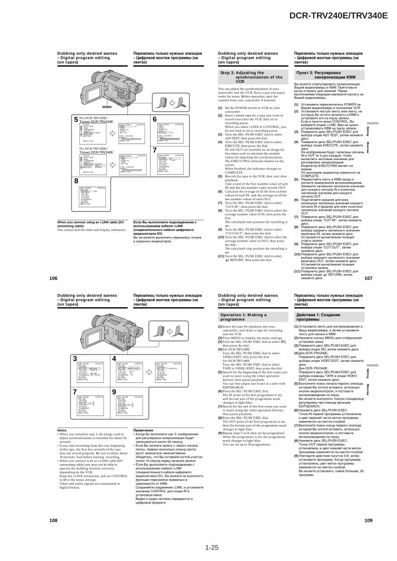
1-25
DCR-TRV240E/TRV340E
106
Dubbing only desired scenes– Digital program editing(on tapes)
When you connect using an i.LINK cable (DVconnecting cable)You cannot dub the titles and display indicators.
5
7
6
8
VIDEO EDIT MARK UNDO ERASE ALL START EDIT SET IR
0:08:55:06
TOTAL 0:00:00:00SCENE 0
[MENU] : END
VIDEO EDIT EDIT SET CONTROL ADJ TEST ”CUT–IN” ”CUT–OUT” IR SETUP PAUSEMODE IR TEST RETURN
IRi. LINK
0:08:55:06
[MENU] : END
i. LINK
VIDEO EDIT EDIT SET CONTROL ADJ TEST ”CUT–IN” ”CUT–OUT” IR SETUP PAUSEMODE IR TEST RETURN
0:08:55:06
[MENU] : END
OTHERS DATA CODE BEEP COMMANDER DISPLAY VIDEO EDIT INDICATOR RETURN
READY
[MENU] : END
VIDEO EDIT MARK UNDO ERASE ALL START EDIT SET
1 IN0:08:55:06
TOTAL 0:00:00:00SCENE 0
[MENU] : END
OTHERS DATA CODE BEEP COMMANDER DISPLAY VIDEO EDIT INDICATOR RETURN
RETURNTAPEMEMORY
[MENU] : END
VIDEO EDIT MARK UNDO ERASE ALL START EDIT SET
1 IN0:08:55:06
TOTAL 0:00:00:00SCENE 0
[MENU] : END
MENU
For DCR-TRV240E:/Только DCR-TRV240E:
For DCR-TRV340E:/Только DCR-TRV340E:
Если Вы выполняете подсоединение сиспользованием кабеля i.LINK(соединительного кабеля цифровоговидеосигнала DV)Вы не можете выполнять перезапись титрови экранных индикаторов.
Перезапись только нужных эпизодов– Цифровой монтаж программы (налентах)
107
Editin
g М
он
таж
Dubbing only desired scenes– Digital program editing(on tapes)
Step 3: Adjusting thesynchronization of theVCR
You can adjust the synchronization of yourcamcorder and the VCR. Have a pen and paperready for notes. Before operation, eject thecassette from your camcorder if inserted.
(1) Set the POWER switch to VCR on yourcamcorder.
(2) Insert a blank tape (or a tape you want torecord over) into the VCR, then set torecording pause.When you select i.LINK in CONTROL, youdo not need to set to recording pause.
(3) Turn the SEL/PUSH EXEC dial to selectADJ TEST, then press the dial.
(4) Turn the SEL/PUSH EXEC dial to selectEXECUTE, then press the dial.IN and OUT are recorded on an image forfive times each to calculate the numbervalues for adjusting the synchronization.The EXECUTING indicator flashes on thescreen.When finished, the indicator changes toCOMPLETE.
(5) Rewind the tape in the VCR, then start slowplayback.Take a note of the first number value of eachIN and the last number value of each OUT.
(6) Calculate the average of all the first numbervalues of each IN, and the average of all thelast number values of each OUT.
(7) Turn the SEL/PUSH EXEC dial to select“CUT-IN”, then press the dial.
(8) Turn the SEL/PUSH EXEC dial to select theaverage number value of IN, then press thedial.The calculated start position for recording isset.
(9) Turn the SEL/PUSH EXEC dial to select“CUT-OUT”, then press the dial.
(10) Turn the SEL/PUSH EXEC dial to select theaverage number value of OUT, then pressthe dial.The calculated stop position for recording isset.
(11) Turn the SEL/PUSH EXEC dial to select RETURN, then press the dial.
Пункт 3: Регулировкасинхронизации КВМ
Вы можете отрегулировать синхронизациюВашей видеокамеры и КВМ. Приготовьтеручку и бумагу для записей. Передвыполнением операции извлеките кассету изВашей видеокамеры.
(1) Установите переключатель POWER наВашей видеокамере в положение VCR.
(2) Установите чистую ленту (или ленту, накоторую Вы хотите записать) в КВМ иустановите его на паузу записи.Если в пункте меню CONTROL, Вывыберете опцию i.LINK, Вам не нужноустанавливать КВМ на паузу записи.
(3) Поверните диск SEL/PUSH EXEC длявыбора опции ADJ TEST, затем нажмитедиск.
(4) Поверните диск SEL/PUSH EXEC длявыбора опции EXECUTE, затем нажмитедиск.На изображении будут записаны сигналыIN и OUT по 5 раз каждый, чтобывычислить числовые значения длярегулировки синхронизации.Индикатор EXECUTING мигает наэкране.По окончании индикатор изменится наCOMPLETE.
(5) Перемотайте ленту в КВМ назад иначните замедленное воспроизведение.Запишите начальное численное значениедля каждого сигнала IN и конечноечисленное значение для каждогосигнала OUT.
(6) Подсчитайте среднее для всехначальных численных значений каждогосигнала IN и среднее для всех конечныхчисленных значений каждого сигналаOUT.
(7) Поверните диск SEL/PUSH EXEC длявыбора опции “CUT-IN”, затем нажмитедиск.
(8) Поверните диск SEL/PUSH EXEC длявыбора среднего численного значениявеличины IN, затем нажмите диск.Установится вычисленная позициястарта записи.
(9) Поверните диск SEL/PUSH EXEC длявыбора опции “CUT-OUT”, затемнажмите диск.
(10) Поверните диск SEL/PUSH EXEC длявыбора среднего численного значениявеличины OUT, затем нажмите диск.Установится вычисленная позицияостановки записи.
(11) Поверните диск SEL/PUSH EXEC длявыбора опции RETURN, затемнажмите диск.
Перезапись только нужных эпизодов– Цифровой монтаж программы (налентах)
108
Notes•When you complete step 3, the image used to
adjust synchronization is recorded for about 50seconds.
•If you start recording from the very beginningof the tape, the first few seconds of the tapemay not record properly. Be sure to allow about10 seconds’ lead before starting recording.
•When you connect with an i.LINK cable (DVconnecting cable) you may not be able tooperate the dubbing function correctly,depending on the VCR.Keep the i.LINK connection, and set CONTROLto IR in the menu settings.Video and audio signals are transmitted indigital format.
Dubbing only desired scenes– Digital program editing(on tapes)
VIDEO EDIT EDIT SET CONTROL ADJ TEST ”CUT–IN” ”CUT–OUT” IR SETUP PAUSEMODE IR TEST RETURN
RETURNEXECUTE
ENGAGEREC PAUSE
0:08:55:06
[MENU] : END
VIDEO EDIT EDIT SET CONTROL ADJ TEST ”CUT–IN” ”CUT–OUT” IR SETUP PAUSEMODE IR TEST RETURN
EXECUTING
No. 5 IN –60
0:08:55:06
[MENU] : END
VIDEO EDIT EDIT SET CONTROL ADJ TEST ”CUT–IN” ”CUT–OUT” IR SETUP PAUSEMODE IR TEST RETURN
0
0:08:55:06
[MENU] : END
0
VIDEO EDIT EDIT SET CONTROL ADJ TEST ”CUT–IN” ”CUT–OUT” IR SETUP PAUSEMODE IR TEST RETURN
0:08:55:06
[MENU] : END
VIDEO EDIT EDIT SET CONTROL ADJ TEST ”CUT–IN” ”CUT–OUT” IR SETUP PAUSEMODE IR TEST RETURN
COMPLETE
0:08:55:06
[MENU] : END
4
9
3
7
Примечания•Когда Вы выполните шаг 3, изображение
для регулировки синхронизации будетзаписываться около 50 секунд.
•Если Вы начнете запись с самого началаленты, первые несколько секунд лентымогут записаться некачественно.Убедитесь, что Вы оставили пустой участококоло 10 секунд перед началом записи.
•Если Вы выполняете подсоединение сиспользованием кабеля i.LINK(соединительного кабеля цифровоговидеосигнала DV), Вы можете не выполнятьфункцию перезаписи правильно взависимости от КВМ.Сохраняйте соединение i.LINK, и установитезначение CONTROL для опции IR вустановках меню.Видео и аудио сигналы передаются вцифровом формате.
Перезапись только нужных эпизодов– Цифровой монтаж программы (налентах)
109
Editin
g М
он
таж
Dubbing only desired scenes– Digital program editing(on tapes)
Operation 1: Making aprogramme
(1) Insert the tape for playback into yourcamcorder, and insert a tape for recordinginto the VCR.
(2) Press MENU to display the menu settings.(3) Turn the SEL/PUSH EXEC dial to select ,
then press the dial.(4) For DCR-TRV240E:
Turn the SEL/PUSH EXEC dial to selectVIDEO EDIT, then press the dial.For DCR-TRV340E:Turn the SEL/PUSH EXEC dial to selectTAPE in VIDEO EDIT, then press the dial.
(5) Search for the beginning of the first scene youwant to insert using the video operationbuttons, then pause playback.You can fine-adjust one frame at a time withEDITSEARCH.
(6) Press the SEL/PUSH EXEC dial.The IN point of the first programme is set,and the top part of the programme markchanges to light blue.
(7) Search for the end of the first scene you wantto insert using the video operation buttons,then pause playback.
(8) Press the SEL/PUSH EXEC dial.The OUT point of the first programme is set,then the bottom part of the programme markchanges to light blue.
(9) Repeat steps 5 to 8, then set the programme.When the programme is set, the programmemark changes to light blue.You can set up to 20 programmes.
Действие 1: Созданиепрограммы
(1) Установите ленту для воспроизведения вВашу видеокамеру, а затем установителенту для записи в КВМ.
(2) Нажмите кнопку MENU для отображенияустановок меню.
(3) Поверните диск SEL/PUSH EXEC длявыбора опции , затем нажмите диск.
(4) Для DCR-TRV240E:Поверните диск SEL/PUSH EXEC длявыбора опции VIDEO EDIT, затем нажмитедиск.Для DCR-TRV340E:Поверните диск SEL/PUSH EXEC длявыбора команды TAPE в опции VIDEOEDIT, затем нажмите диск.
(5) Выполните поиск начала первого эпизода,который Вы хотите вставить, используякнопки видеоконтроля, и поставьтевоспроизведение на паузу.Вы можете выполнить тонкую покадровуюрегулировку при помощи функцииEDITSEARCH.
(6) Нажмите диск SEL/PUSH EXEC.Точка IN первой программы установлена,и цвет верхней части метки программыизменяется на светло-голубой.
(7) Выполните поиск конца первого эпизода,который Вы хотите вставить, используякнопки видеоконтроля, и поставьтевоспроизведение на паузу.
(8) Нажмите диск SEL/PUSH EXEC.Точка OUT первой программыустановлена, и цвет нижней части меткипрограммы изменяется на светло-голубой.
(9) Повторите действия пунктов 5-8, затемустановите программу. Когда программаустановлена, цвет метки программыизменяется на светло-голубой.Вы можете установить, самое большее, 20программ.
Перезапись только нужных эпизодов– Цифровой монтаж программы (налентах)
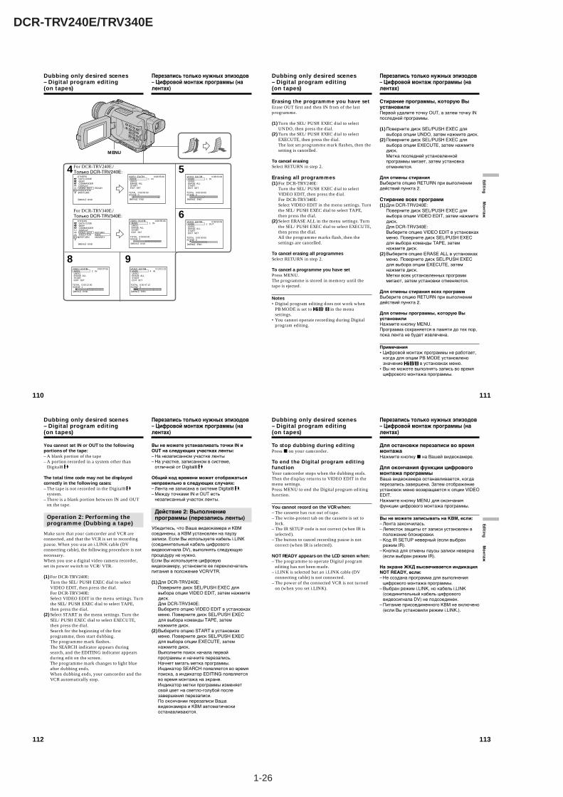
1-26
DCR-TRV240E/TRV340E
112
Dubbing only desired scenes– Digital program editing(on tapes)
You cannot set IN or OUT to the followingportions of the tape:– A blank portion of the tape– A portion recorded in a system other than
Digital8
The total time code may not be displayedcorrectly in the following cases:– The tape is not recorded in the Digital8
system.– There is a blank portion between IN and OUT
on the tape.
Operation 2: Performing theprogramme (Dubbing a tape)
Make sure that your camcorder and VCR areconnected, and that the VCR is set to recordingpause. When you use an i.LINK cable (DVconnecting cable), the following procedure is notnecessary.When you use a digital video camera recorder,set its power switch to VCR/VTR.
(1) For DCR-TRV240E:Turn the SEL/PUSH EXEC dial to selectVIDEO EDIT, then press the dial.For DCR-TRV340E:Select VIDEO EDIT in the menu settings. Turnthe SEL/PUSH EXEC dial to select TAPE,then press the dial.
(2) Select START in the menu settings. Turn theSEL/PUSH EXEC dial to select EXECUTE,then press the dial.Search for the beginning of the firstprogramme, then start dubbing.The programme mark flashes.The SEARCH indicator appears duringsearch, and the EDITING indicator appearsduring edit on the screen.The programme mark changes to light blueafter dubbing ends.When dubbing ends, your camcorder and theVCR automatically stop.
Вы не можете устанавливать точки IN иOUT на следующих участках ленты:– На незаписанном участке ленты– На участке, записанном в системе,
отличной от Digital8
Общий код времени может отображатьсянеправильно в следующих случаях:– Лента не записана в системе Digital8 .– Между точками IN и OUT есть
незаписанный участок ленты.
Действие 2: Выполнениепрограммы (перезапись ленты)
Убедитесь, что Ваша видеокамера и КВМсоединены, а КВМ установлен на паузузаписи. Если Вы используете кабель i.LINK(соединительный кабель цифровоговидеосигнала DV), выполнять следующуюпроцедуру не нужно.Если Вы используете цифровуювидеокамеру, установите ее переключательпитания в положение VCR/VTR.
(1)Для DCR-TRV240E:Поверните диск SEL/PUSH EXEC длявыбора опции VIDEO EDIT, затем нажмитедиск.Для DCR-TRV340E:Выберите опцию VIDEO EDIT в установкахменю. Поверните диск SEL/PUSH EXECдля выбора команды TAPE, затемнажмите диск.
(2)Выберите опцию START в установкахменю. Поверните диск SEL/PUSH EXECдля выбора опции EXECUTE, затемнажмите диск.Выполните поиск начала первойпрограммы и начните перезапись.Начнет мигать метка программы.Индикатор SEARCH появляется во времяпоиска, а индикатор EDITING появляетсяво время монтажа на экране.Индикатор метки программы изменяетсвой цвет на светло-голубой послезавершения перезаписи.По окончании перезаписи Вашавидеокамера и КВМ автоматическиостанавливаются.
Перезапись только нужных эпизодов– Цифровой монтаж программы (налентах)
113
Editin
g М
он
таж
To stop dubbing during editingPress x on your camcorder.
To end the Digital program editingfunctionYour camcorder stops when the dubbing ends.Then the display returns to VIDEO EDIT in themenu settings.Press MENU to end the Digital program editingfunction.
You cannot record on the VCR when:– The cassette has run out of tape.– The write-protect tab on the cassette is set to
lock.– The IR SETUP code is not correct (when IR is
selected).– The button to cancel recording pause is not
correct (when IR is selected).
NOT READY appears on the LCD screen when:– The programme to operate Digital program
editing has not been made.– i.LINK is selected but an i.LINK cable (DV
connecting cable) is not connected.– The power of the connected VCR is not turned
on (when you set i.LINK).
Dubbing only desired scenes– Digital program editing(on tapes)
Для остановки перезаписи во времямонтажаНажмите кнопку x на Вашей видеокамере.
Для окончания функции цифровогомонтажа программыВаша видеокамера останавливается, когдаперезапись завершена. Затем отображениеустановок меню возвращается к опции VIDEOEDIT.Нажмите кнопку MENU для окончанияфункции цифрового монтажа программы.
Вы не можете записывать на КВМ, если:– Лента закончилась.– Лепесток защиты от записи установлен в
положение блокировки.– Код IR SETUP неверный (если выбран
режим IR).– Кнопка для отмены паузы записи неверна
(если выбран режим IR).
На экране ЖКД высвечивается индикацияNOT READY, если:– Не создана программа для выполнения
цифрового монтажа программы.– Выбран режим i.LINK, но кабель i.LINK
(соединительный кабель цифровоговидеосигнала DV) не подсоединен.
– Питание присоединенного КВМ не включено(если Вы установили режим i.LINK.).
Перезапись только нужных эпизодов– Цифровой монтаж программы (налентах)
110
Dubbing only desired scenes– Digital program editing(on tapes)
5
6
8 9
VIDEO EDIT MARK UNDO ERASE ALL START EDIT SET
1 IN0:08:55:06
TOTAL 0:00:00:00SCENE 0
[MENU] : END
VIDEO EDIT MARK UNDO ERASE ALL START EDIT SET
1 OUT0:08:55:06
TOTAL 0:00:00:00SCENE 0
[MENU] : END
VIDEO EDIT MARK UNDO ERASE ALL START EDIT SET
4 IN0:10:01:23
TOTAL 0:00:47:12SCENE 3
[MENU] : END
VIDEO EDIT MARK UNDO ERASE ALL START EDIT SET
2 IN0:09:07:06
TOTAL 0:00:12:00SCENE 1
[MENU] : END
4
VIDEO EDIT MARK UNDO ERASE ALL START EDIT SET
1 IN0:08:55:06
TOTAL 0:00:00:00SCENE 0
[MENU] : END
OTHERS DATA CODE BEEP COMMANDER DISPLAY VIDEO EDIT INDICATOR RETURN
RETURNTAPEMEMORY
[MENU] : END
OTHERS DATA CODE BEEP COMMANDER DISPLAY VIDEO EDIT INDICATOR RETURN
READY
[MENU] : END
VIDEO EDIT MARK UNDO ERASE ALL START EDIT SET
1 IN0:08:55:06
TOTAL 0:00:00:00SCENE 0
[MENU] : END
MENU
For DCR-TRV240E:/Только DCR-TRV240E:
For DCR-TRV340E:/Только DCR-TRV340E:
Перезапись только нужных эпизодов– Цифровой монтаж программы (налентах)
111
Editin
g М
он
тажDubbing only desired scenes– Digital program editing(on tapes)
Erasing the programme you have setErase OUT first and then IN from of the lastprogramme.
(1) Turn the SEL/PUSH EXEC dial to selectUNDO, then press the dial.
(2) Turn the SEL/PUSH EXEC dial to selectEXECUTE, then press the dial.The last set programme mark flashes, then thesetting is cancelled.
To cancel erasingSelect RETURN in step 2.
Erasing all programmes(1) For DCR-TRV240E:
Turn the SEL/PUSH EXEC dial to selectVIDEO EDIT, then press the dial.For DCR-TRV340E:Select VIDEO EDIT in the menu settings. Turnthe SEL/PUSH EXEC dial to select TAPE,then press the dial.
(2) Select ERASE ALL in the menu settings. Turnthe SEL/PUSH EXEC dial to select EXECUTE,then press the dial.All the programme marks flash, then thesettings are cancelled.
To cancel erasing all programmesSelect RETURN in step 2.
To cancel a programme you have setPress MENU.The programme is stored in memory until thetape is ejected.
Notes•Digital program editing does not work when
PB MODE is set to / in the menusettings.
•You cannot operate recording during Digitalprogram editing.
Стирание программы, которую ВыустановилиПервой удалите точку OUT, а затем точку INпоследней программы.
(1) Поверните диск SEL/PUSH EXEC длявыбора опции UNDO, затем нажмите диск.
(2) Поверните диск SEL/PUSH EXEC длявыбора опции EXECUTE, затем нажмитедиск.Метка последней установленнойпрограммы мигает, затем установкаотменяется.
Для отмены стиранияВыберите опцию RETURN при выполнениидействий пункта 2.
Стирание всех программ(1) Для DCR-TRV240E:
Поверните диск SEL/PUSH EXEC длявыбора опции VIDEO EDIT, затем нажмитедиск.Для DCR-TRV340E:Выберите опцию VIDEO EDIT в установкахменю. Поверните диск SEL/PUSH EXECдля выбора команды TAPE, затемнажмите диск.
(2) Выберите опцию ERASE ALL в установкахменю. Поверните диск SEL/PUSH EXECдля выбора опции EXECUTE, затемнажмите диск.Метки всех установленных программмигают, затем установки отменяются.
Для отмены стирания всех программВыберите опцию RETURN при выполнениидействий пункта 2.
Для отмены программы, которую ВыустановилиНажмите кнопку MENU.Программа сохраняется в памяти до тех пор,пока лента не будет извлечена.
Примечания•Цифровой монтаж программы не работает,
когда для опции PB MODE установленозначение / в установках меню.
•Вы не можете выполнять запись во времяцифрового монтажа программы.
Перезапись только нужных эпизодов– Цифровой монтаж программы (налентах)
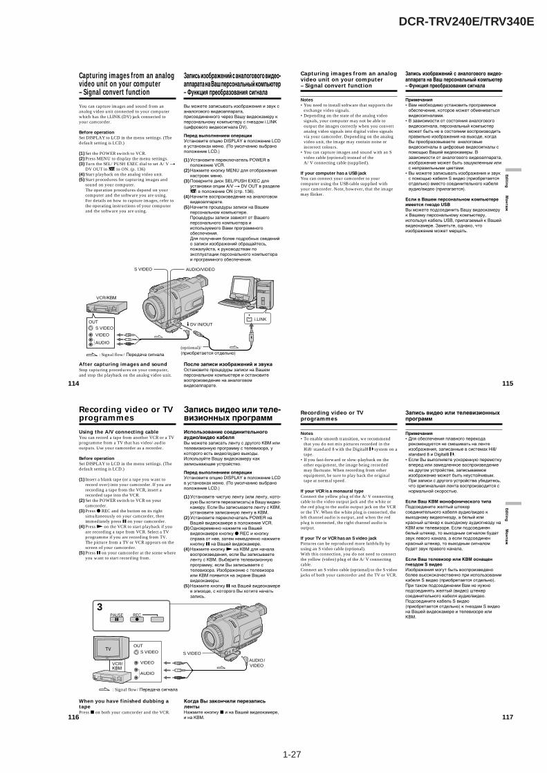
1-27
DCR-TRV240E/TRV340E
114
Capturing images from an analogvideo unit on your computer– Signal convert function
You can capture images and sound from ananalog video unit connected to your computerwhich has the i.LINK (DV) jack connected toyour camcorder.
Before operationSet DISPLAY to LCD in the menu settings. (Thedefault setting is LCD.)
(1) Set the POWER switch to VCR.(2) Press MENU to display the menu settings.(3) Turn the SEL/PUSH EXEC dial to set A/V t
DV OUT in to ON. (p. 136)(4) Start playback on the analog video unit.(5) Start procedures for capturing images and
sound on your computer.The operation procedures depend on yourcomputer and the software you are using.For details on how to capture images, refer tothe operating instructions of your computerand the software you are using.
After capturing images and soundStop capturing procedures on your computer,and stop the playback on the analog video unit.
Вы можете записывать изображения и звук саналогового видеоаппарата,присоединенного через Вашу видеокамеру кперсональному компьютеру с гнездом i.LINK(цифрового видеосигнала DV).
Перед выполнением операцииУстановите опцию DISPLAY в положение LCDв установках меню. (По умолчанию выбраноположение LCD.)
(1) Установите переключатель POWER вположение VCR.
(2) Нажмите кнопку MENU для отображениянастроек меню.
(3) Поверните диск SEL/PUSH EXEC дляустановки опции A/V t DV OUT в разделе
в положение ON (стр. 136).(4) Начните воспроизведение на аналоговом
видеоаппарате.(5) Начните процедуры записи на Вашем
персональном компьютере.Процедуры записи зависят от Вашегоперсонального компьютера ииспользуемого Вами программногообеспечения.Для получения более подробных сведенийо записи изображений обращайтесь,пожалуйста, к руководствам поэксплуатации персонального компьютераи программного обеспечения.
После записи изображений и звукаОстановите процедуры записи на Вашемперсональном компьютере и остановитевоспроизведение на аналоговомвидеоаппарате.
Запись изображений с аналогового видео-аппарата на Ваш персональный компьютер– Функция преобразования сигнала
i.LINK
VIDEO
AUDIO
S VIDEOOUT
AUDIO/VIDEOS VIDEO
DV IN/OUT
(optional)/(приобретается отдельно) : Signal flow/Передача сигнала
VCR/КВМ
115
Editin
g М
он
таж
Capturing images from an analogvideo unit on your computer– Signal convert function
Notes•You need to install software that supports the
exchange video signals.•Depending on the state of the analog video
signals, your computer may not be able tooutput the images correctly when you convertanalog video signals into digital video signalsvia your camcorder. Depending on the analogvideo unit, the image may contain noise orincorrect colours.
•You can capture images and sound with an Svideo cable (optional) instead of theA/V connecting cable (supplied).
If your computer has a USB jackYou can connect your camcorder to yourcomputer using the USB cable supplied withyour camcorder. Note, however, that the imagemay flicker.
Запись изображений с аналогового видео-аппарата на Ваш персональный компьютер– Функция преобразования сигнала
Примечания•Вам необходимо установить программное
обеспечение, которое может обмениватьсявидеосигналами.
•В зависимости от состояния аналоговоговидеосигнала, персональный компьютерможет быть не в состоянии воспроизводитьправильно изображения на выходе, когдаВы преобразовываете аналоговыевидеосигналы в цифровые видеосигналы спомощью Вашей видеокамеры. Взависимости от аналогового видеоаппарата,изображение может быть зашумленным илис неправильными цветами.
•Вы можете записывать изображения и звукс помощью кабеля S видео (приобретаетсяотдельно) вместо соединительного кабеляаудио/видео (прилагается).
Если в Вашем персональном компьютереимеется гнездо USBВы можете подсоединить Вашу видеокамерук Вашему персональному компьютеру,используя кабель USB, прилагаемый к Вашейвидеокамере. Заметьте, однако, чтоизображение может мерцать.
116
Recording video or TVprogrammes
Using the A/V connecting cableYou can record a tape from another VCR or a TVprogramme from a TV that has video/audiooutputs. Use your camcorder as a recorder.
Before operationSet DISPLAY to LCD in the menu settings. (Thedefault setting is LCD.)
(1) Insert a blank tape (or a tape you want torecord over) into your camcorder. If you arerecording a tape from the VCR, insert arecorded tape into the VCR.
(2) Set the POWER switch to VCR on yourcamcorder.
(3) Press z REC and the button on its rightsimultaneously on your camcorder, thenimmediately press X on your camcorder.
(4) Press N on the VCR to start playback if youare recording a tape from VCR. Select a TVprogramme if you are recording from TV.The picture from a TV or VCR appears on thescreen of your camcorder.
(5) Press X on your camcorder at the scene whereyou want to start recording from.
When you have finished dubbing atapePress x on both your camcorder and the VCR.
Запись видео или теле-визионных программ
Использование соединительногоаудио/видео кабеляВы можете записать ленту с другого КВМ илителевизионную программу с телевизора, укоторого есть видео/аудио выходы.Используйте Вашу видеокамеру какзаписывающее устройство.
Перед выполнением операцииУстановите опцию DISPLAY в положение LCDв установках меню. (По умолчанию выбраноположение LCD.)
(1) Установите чистую ленту (или ленту, кото-рую Вы хотите перезаписать) в Вашу видео-камеру. Если Вы записываете ленту с КВМ,установите записанную ленту в КВМ.
(2) Установите переключатель POWER наВашей видеокамере в положение VCR.
(3) Одновременно нажмите на Вашейвидеокамере кнопку z REC и кнопкусправа от нее, затем немедленно нажмитекнопку X на Вашей видеокамере.
(4) Нажмите кнопку N на КВМ для началавоспроизведения, если Вы записываетеленту с КВМ. Выберите телевизионнуюпрограмму, если Вы записываете стелевизора. Изображение с телевизораили КВМ появится на экране Вашейвидеокамеры.
(5) Нажмите кнопку X на Вашей видеокамерев эпизоде, с которого Вы хотите начатьзапись.
Когда Вы закончили перезаписьлентыНажмите кнопку x и на Вашей видеокамере,и на КВМ.
: Signal flow/Передача сигнала
S VIDEO
VIDEO
AUDIO
OUT
S VIDEO
AUDIO / VIDEO
3PAUSE REC
VCR/КВМ
117
Editin
g М
он
таж
Recording video or TVprogrammes
Notes•To enable smooth transition, we recommend
that you do not mix pictures recorded in theHi8/standard 8 with the Digital8 system on atape.
•If you fast-forward or slow-playback on theother equipment, the image being recordedmay fluctuate. When recording from otherequipment, be sure to play back the originaltape at normal speed.
If your VCR is a monaural typeConnect the yellow plug of the A/V connectingcable to the video output jack and the white orthe red plug to the audio output jack on the VCRor the TV. When the white plug is connected, theleft channel audio is output, and when the redplug is connected, the right channel audio isoutput.
If your TV or VCR has an S video jackPictures can be reproduced more faithfully byusing an S video cable (optional).With this connection, you do not need to connectthe yellow (video) plug of the A/V connectingcable.Connect an S video cable (optional) to the S videojacks of both your camcorder and the TV or VCR.
Запись видео или телевизионныхпрограмм
Примечания•Для обеспечения плавного перехода
рекомендуется не смешивать на лентеизображения, записанные в системах Hi8/standard 8 и Digital8 .
•Если Вы выполняете ускоренную перемоткувперед или замедленное воспроизведениена другом устройстве, записываемоеизображение может быть неустойчивым.При записи с другого устройства убедитесь,что оригинальная лента воспроизводится снормальной скоростью.
Если Ваш КВМ монофонического типаПодсоедините желтый штекерсоединительного кабеля аудио/видео квыходному видеогнезду, а белый иликрасный штекер к выходному аудиогнезду наКВМ или телевизоре. Если подсоединенбелый штекер, то выходным сигналом будетзвук левого канала, а если подсоединенкрасный штекер, то выходным сигналомбудет звук правого канала.
Если Ваш телевизор или КВМ оснащенгнездом S видеоИзображения могут быть воспроизведеноболее высококачественно при использованиикабеля S видео (приобретается отдельно).При таком подсоединении Вам не нужноподсоединять желтый (видео) штекерсоединительного кабеля аудио/видео.Подсоедините кабель S видео(приобретается отдельно) к гнездам S видеона Вашей видеокамере и телевизоре илиКВМ.
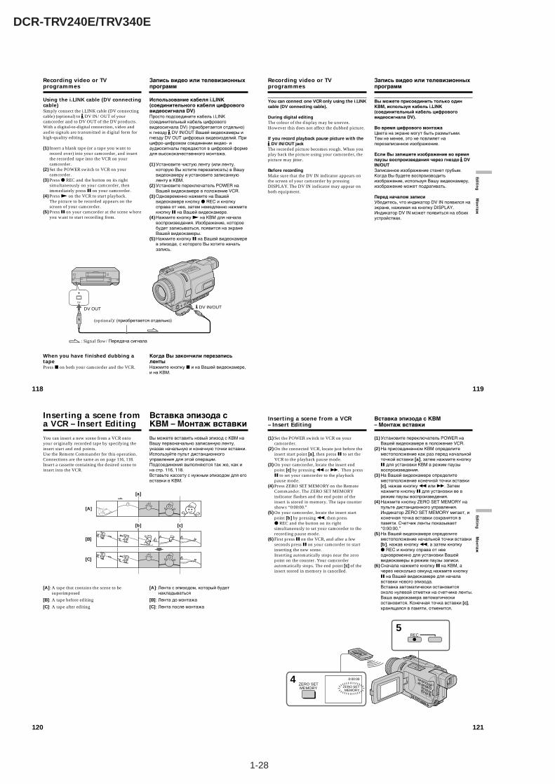
1-28
DCR-TRV240E/TRV340E
120
You can insert a new scene from a VCR ontoyour originally recorded tape by specifying theinsert start and end points.Use the Remote Commander for this operation.Connections are the same as on page 116, 118.Insert a cassette containing the desired scene toinsert into the VCR.
[A]: A tape that contains the scene to besuperimposed
[B]: A tape before editing
[C]: A tape after editing
Inserting a scene froma VCR – Insert Editing
Вы можете вставить новый эпизод с КВМ наВашу первоначально записанную ленту,указав начальную и конечную точки вставки.Используйте пульт дистанционногоуправления для этой операции.Подсоединения выполняются так же, как ина стр. 116, 118.Вставьте кассету с нужным эпизодом для еговставки в КВМ.
[A]: Лента с эпизодом, который будетнакладываться
[B]: Лента до монтажа
[C]: Лента после монтажа
Вставка эпизода сКВМ – Монтаж вставки
[a]
[b] [c]
[A]
[B]
[C]
121
Editin
g М
он
таж
Inserting a scene from a VCR– Insert Editing
(1) Set the POWER switch to VCR on yourcamcorder.
(2) On the connected VCR, locate just before theinsert start point [a], then press X to set theVCR to the playback pause mode.
(3) On your camcorder, locate the insert endpoint [c] by pressing m or M. Then pressX to set your camcorder to the playbackpause mode.
(4) Press ZERO SET MEMORY on the RemoteCommander. The ZERO SET MEMORYindicator flashes and the end point of theinsert is stored in memory. The tape countershows “0:00:00.”
(5) On your camcorder, locate the insert startpoint [b] by pressing m, then pressz REC and the button on its rightsimultaneously to set your camcorder to therecording pause mode.
(6) First press X on the VCR, and after a fewseconds press X on your camcorder to startinserting the new scene.Inserting automatically stops near the zeropoint on the counter. Your camcorderautomatically stops. The end point [c] of theinsert stored in memory is cancelled.
4ZERO SETMEMORY
5
0:00:00
ZERO SETMEMORY
REC
Вставка эпизода с КВМ– Монтаж вставки
(1) Установите переключатель POWER наВашей видеокамере в положение VCR.
(2) На присоединенном КВМ определитеместоположение как раз перед начальнойточкой вставки [a], затем нажмите кнопкуX для установки КВМ в режим паузывоспроизведения.
(3) На Вашей видеокамере определитеместоположение конечной точки вставки[c], нажав кнопку m или M. Затемнажмите кнопку X для установки ее врежим паузы воспроизведения.
(4) Нажмите кнопку ZERO SET MEMORY напульте дистанционного управления.Индикатор ZERO SET MEMORY мигает, иконечная точка вставки сохранятся впамяти. Счетчик ленты показывает“0:00:00.”
(5) На Вашей видеокамере определитеместоположение начальной точки вставки[b], нажав кнопку m, а затем кнопкуz REC и кнопку справа от нееодновременно для установки Вашейвидеокамеры в режим паузы записи.
(6) Сначала нажмите кнопку X на КВМ, ачерез несколько секунд нажмите кнопкуX на Вашей видеокамере для началавставки нового эпизода.Вставка автоматически остановитсяоколо нулевой отметки на счетчике ленты.Ваша видеокамера автоматическиостановится. Конечная точка вставки [c],хранящаяся в памяти, отменится.
118
Recording video or TVprogrammes
Using the i.LINK cable (DV connectingcable)Simply connect the i.LINK cable (DV connectingcable) (optional) to DV IN/OUT of yourcamcorder and to DV OUT of the DV products.With a digital-to-digital connection, video andaudio signals are transmitted in digital form forhigh-quality editing.
(1) Insert a blank tape (or a tape you want torecord over) into your camcorder, and insertthe recorded tape into the VCR on yourcamcorder.
(2) Set the POWER switch to VCR on yourcamcorder.
(3) Press z REC and the button on its rightsimultaneously on your camcorder, thenimmediately press X on your camcorder.
(4) Press N on the VCR to start playback.The picture to be recorded appears on thescreen of your camcorder.
(5) Press X on your camcorder at the scene whereyou want to start recording from.
When you have finished dubbing atapePress x on both your camcorder and the VCR.
Запись видео или телевизионныхпрограмм
Использование кабеля i.LINK(соединительного кабеля цифровоговидеосигнала DV)Просто подсоедините кабель i.LINK(соединительный кабель цифровоговидеосигнала DV) (приобретается отдельно)к гнезду DV IN/OUT Вашей видеокамеры игнезду DV OUT цифровых видеоизделий. Прицифро-цифровом соединении видео- иаудиосигналы передаются в цифровой формедля высококачественного монтажа.
(1) Установите чистую ленту (или ленту,которую Вы хотите перезаписать) в Вашувидеокамеру и установите записаннуюленту в КВМ.
(2) Установите переключатель POWER наВашей видеокамере в положение VCR.
(3) Одновременно нажмите на Вашейвидеокамере кнопку z REC и кнопкусправа от нее, затем немедленно нажмитекнопку X на Вашей видеокамере.
(4) Нажмите кнопку N на КВМ для началавоспроизведения. Изображение, котороебудет записываться, появится на экранеВашей видеокамеры.
(5) Нажмите кнопку X на Вашей видеокамерев эпизоде, с которого Вы хотите начатьзапись.
Когда Вы закончили перезаписьлентыНажмите кнопку x и на Вашей видеокамере,и на КВМ.
: Signal flow/Передача сигнала
(optional)/(приобретается отдельно)
DV
DV OUT DV IN/OUT
119
Editin
g М
он
таж
You can connect one VCR only using the i.LINKcable (DV connecting cable).
During digital editingThe colour of the display may be uneven.However this does not affect the dubbed picture.
If you record playback pause picture with the DV IN/OUT jack
The recorded picture becomes rough. When youplay back the picture using your camcorder, thepicture may jitter.
Before recordingMake sure that the DV IN indicator appears onthe screen of your camcorder by pressingDISPLAY. The DV IN indicator may appear onboth equipment.
Recording video or TVprogrammes
Вы можете присоединить только одинКВМ, используя кабель i.LINK(соединительный кабель цифровоговидеосигнала DV).
Во время цифрового монтажаЦвета на экране могут быть размытыми.Тем не менее, это не повлияет наперезаписанное изображение.
Если Вы запишете изображение во времяпаузы воспроизведения через гнездо DVIN/OUTЗаписанное изображение станет грубым.Когда Вы будете воспроизводитьизображение, используя Вашу видеокамеру,изображение может подрагивать.
Перед началом записиУбедитесь, что индикатор DV IN появился наэкране, нажимая на кнопку DISPLAY.Индикатор DV IN может появиться на обоихустройствах.
Запись видео или телевизионныхпрограмм
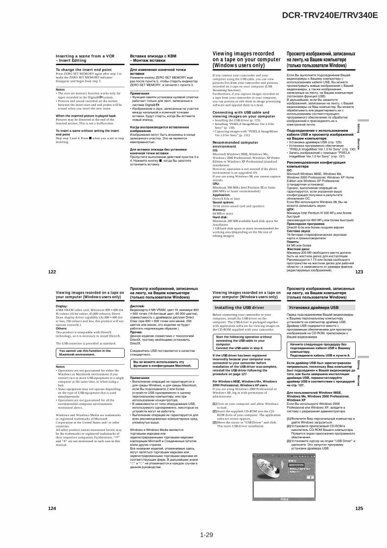
1-29
DCR-TRV240E/TRV340E
122
Inserting a scene from a VCR– Insert Editing
To change the insert end pointPress ZERO SET MEMORY again after step 5 tomake the ZERO SET MEMORY indicatordisappear and begin from step 3.
Notes•The zero set memory function works only for
tapes recorded in the Digital8 system.•Pictures and sound recorded on the section
between the insert start and end points will beerased when you insert the new scene.
When the inserted picture is played backPictures may be distorted at the end of theinserted section. This is not a malfunction.
To insert a scene without setting the insertend pointSkip step 3 and 4. Press x when you want to stopinserting.
Вставка эпизода с КВМ– Монтаж вставки
Для изменения конечной точкивставкиНажмите кнопку ZERO SET MEMORY ещераз после пункта 5, чтобы стереть индикаторZERO SET MEMORY, и начните с пункта 3.
Примечания•Функция памяти установки нулевой отметки
работает только для лент, записанных всистеме Digital8 .
•Изображение и звук, записанные на участкемежду начальной и конечной точкамивставки, будут стерты, когда Вы вставитеновый эпизод.
Когда воспроизводится вставленноеизображениеИзображения могут быть искажены в концезаписанного участка. Это не являетсянеисправностью.
Для вставки эпизода без установкиконечной точки вставкиПропустите выполнение действий пунктов 3 и4. Нажмите кнопку x, когда Вы захотитеостановить вставку.
123
Editin
g М
он
таж
If you connect your camcorder and yourcomputer using the USB cable, you can viewpictures live from your camcorder and picturesrecorded on a tape on your computer (USBStreaming function).Furthermore, if you capture images recorded ona tape from your camcorder to your computer,you can process or edit them in image processingsoftware and append them to e-mail.
Connecting with USB cable andviewing images on your computer•Installing the USB driver (p. 125)•Installing “PIXELA ImageMixer Ver.1.0 for
Sony” (p. 130)•Capturing images with “PIXELA ImageMixer
Ver.1.0 for Sony” (p. 131)
Recommended computerenvironmentOS:Microsoft Windows 98SE, Windows Me,Windows 2000 Professional, Windows XP HomeEdition or Windows XP Professional (standardinstallation)However, operation is not assured if the aboveenvironment is an upgraded OS.If you are using Windows 98, you cannot capturesounds.CPU:Minimum 500 MHz Intel Pentium III or faster(800 MHz or faster recommended)Application:DirectX 8.0a or laterSound system:16 bit stereo sound card and speakersMemory:64 MB or moreHard disk:Minimum 200 MB available hard disk space forinstallation1 GB hard disk space or more recommended forworking area (depending on the file size ofediting images)
Viewing images recordedon a tape on your computer(Windows users only)
Если Вы выполните подсоединение Вашейвидеокамеры к Вашему компьютеру сиспользованием кабеля USB, Вы можетепросматривать живые изображения с Вашейвидеокамеры, а также изображения,записанные на ленту, на Вашем компьютере(потоковая функция USB).В дальнейшем, если Вы захватитеизображения, записанные на ленту, с Вашейвидеокамеры на Ваш компьютер, Вы можетеобрабатывать или редактировать их сиспользованием соответствующегопрограммного обеспечения по обработкеизображений и присоединять их кэлектронной почте.
Подсоединение с использованиемкабеля USB и просмотр изображенийна Вашем компьютере•Установка драйвера USB (стр. 125)•Установка программного обеспечения
“PIXELA ImageMixer Ver.1.0 for Sony” (стр. 130)•Запись изображений с помощью “PIXELA
ImageMixer Ver.1.0 for Sony” (стр. 131)
Рекомендованная конфигурациякомпьютераОС:Microsoft Windows 98SE, Windows Me,Windows 2000 Professional, Windows XP HomeEdition или Windows XP Professional(стандартная установка)Однако, выполнение операций негарантируется, если указанная вышеконфигурация получена в результатеобновления ОС.Если ВЫ используете Windows 98, Вы неможете записывать звуки.ЦПУ:Минимум Intel Pentium III 500 МГц или болеебыстрый(рекомендуется 800 МГц или более быстрый)Прикладная программа:DirectX 8.0a или более поздняя версияСистема звука:16-битовая стереофоническая звуковаякарта и громкоговорителиПамять:64 Мб или болееЖесткий диск:Минимум 200 Мб свободного места должнобыть на жестком диске для инсталляцииРекомендуется 1 Гб или более свободногопространства на жестком диске для рабочейобласти ( в зависимости от размера файловредактируемых изображений).
Просмотр изображений, записанныхна ленту, на Вашем компьютере(только пользователи Windows)
124
Viewing images recorded on a tape onyour computer (Windows users only)
Display:4 MB VRAM video card, Minimum 800 × 600 dotHi colour (16 bit colour, 65,000 colours), DirectDraw display driver capability (At 800 × 600 dotor less, 256 colours and less, this product will notoperate correctly.)Others:This product is compatible with DirectXtechnology, so it is necessary to install DirectX.
The USB connector is provided as standard.
You cannot use this function in theMacintosh environment.
Notes•Operations are not guaranteed for either the
Windows or Macintosh environment if youconnect two or more USB equipment to a singlecomputer at the same time, or when using ahub.
•Some equipment may not operate dependingon the type of USB equipment that is usedsimultaneously.
•Operations are not guaranteed for all therecommended computer environmentsmentioned above.
Windows and Windows Media are trademarksor registered trademarks of MicrosoftCorporation in the United States and/or othercountries.All other product names mentioned herein maybe the trademarks or registered trademarks oftheir respective companies. Furthermore, “™”and “®” are not mentioned in each case in thismanual.
Дисплей:Видеокарта 4 Мб VRAM, цвет Hi, минимум 800× 600 точек (16-битовый цвет, 65 000 цветов),совместимость с драйвером дисплея DirectDraw (при 800 × 600 точек или менее, 256цветов или менее, это изделие не будетработать надлежащим образом.)Прочее:Данное изделие совместимо с технологиейDirectX, поэтому необходимо установитьDirectX.
Соединитель USB поставляется в качествестандартного.
Вы не можете использовать этуфункцию в конфигурации Macintosh.
Примечания•Выполнение операций не гарантируется и
для среды Windows, и для среды Macintosh,если Вы подсоедините 2 или болееустройств USB одновременно к одномуперсональному компьютеру, или прииспользовании концентратора.
•В зависимости от типа оборудования USB,используемого одновременно, некоторые изустройств могут не работать.
•Выполнение операций не гарантируется длявсех рекомендованных компьютерных сред,упомянутых выше.
Windows и Windows Media являютсяторговыми марками илизарегистрированными торговыми маркамикорпорации Microsoft в Соединенных Штатахи/или других странах.Все названия изделий, упоминаемые здесь,могут являться торговыми марками илизарегистрированными торговыми марками ихсоответствующих фирм. В дальнейшем знаки“ ” и “ ” не упоминаются в каждом случае вданном руководстве.
Просмотр изображений, записанныхна ленту, на Вашем компьютере(только пользователи Windows)
125
Editin
g М
он
таж
Viewing images recorded on a tape onyour computer (Windows users only)
Installing the USB driver
Before connecting your camcorder to yourcomputer, install the USB driver on thecomputer. The USB driver is packaged togetherwith application software for viewing images onthe CD-ROM supplied with your camcorder.
Start the following operation withoutconnecting the USB cable to yourcomputer.Connect the USB cable in step 8.
If the USB driver has been registeredincorrectly because your computer wasconnected to your camcorder beforeinstallation of the USB driver was complete,reinstall the USB driver following theprocedure on page 127.
For Windows 98SE, Windows Me, Windows2000 Professional, Windows XP usersIf you are using Windows 2000 Professional orWindows XP, log in with permission ofadministrator.
(1) Turn on your computer and allow Windowsto load.
(2) Insert the supplied CD-ROM into the CD-ROM drive of your computer. The applicationsoftware screen appears.
(3) Move the cursor to “USB Driver” and click.This starts USB driver installation.
Просмотр изображений, записанныхна ленту, на Вашем компьютере(только пользователи Windows)
Установка драйвера USB
Перед подсоединением Вашей видеокамерык Вашему персональному компьютеруустановите на компьютер драйвер USB.Драйвер USB содержится вместе спрограммным обеспечением для просмотраизображений на CD-ROM, прилагаемом кВашей видеокамере.
Начните следующую процедуру безподсоединения кабеля USB к Вашемукомпьютеру.Подсоедините кабель USB в пункте 8.
Если драйвер USB был зарегистрированнеправильно, поскольку Ваш компьютербыл подсоединен к Вашей видеокамере дотого, как была завершена инсталляциядрайвера USB, переинсталлируйтедрайвер USB в соответствии с процедуройна стр. 127.
Для пользователей Windows 98SE,Windows Me, Windows 2000 Professional,Windows XPЕсли Вы используете Windows 2000Professional или Windows XP, войдите всистему с разрешения администратора.
(1) Включите Ваш персональный компьютер идайте Windows загрузиться.
(2) Установите прилагаемый CD-ROM внакопитель CD-ROM Вашего компьютера.Появится экран приложения программногообеспечения.
(3) Установите курсор на опции “USB Driver” ищелкните. Это запустит программуустановки драйвера USB.
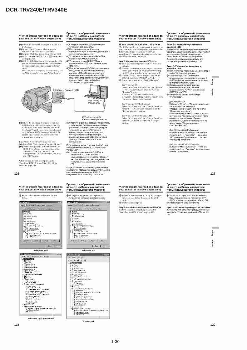
1-30
DCR-TRV240E/TRV340E
128
5 Select and delete the underlined devicesbelow.
Viewing images recorded on a tape onyour computer (Windows users only)
Windows 98SE Windows Me
Windows 2000 ProfessionalWindows XP
Просмотр изображений, записанныхна ленту, на Вашем компьютере(только пользователи Windows)
5 Выберите и удалите подчеркнутыеустройства, которые приведены ниже.
129
Editin
g М
он
таж
6 Set the POWER switch to OFF (CHG) on yourcamcorder, and then disconnect the USBcable.
7 Restart your computer.
Step 2: Install the USB driver on the CD-ROMPerform the entire procedure described in“Installing the USB driver” on page 125.
Viewing images recorded on a tape onyour computer (Windows users only)
Просмотр изображений, записанныхна ленту, на Вашем компьютере(только пользователи Windows)
6 Установите переключатель POWER наВашей видеокамере в положение OFF(CHG), а затем отсоедините кабель USB.
7 Перезагрузите Ваш компьютер.
Пункт 2: Установка драйвера USB с CD-ROMВыполните полностью процедуру, описаннуюв разделе “Установка драйвера USB” на стр.125.
126
(4) Follow the on-screen messages to install theUSB driver.
(5) Connect the AC power adaptor to yourcamcorder and then to a wall socket.
(6) Set the POWER switch to CAMERA or VCR.(7) Select USB STREAM to ON in in the menu
settings (p.136).(8) With the CD-ROM inserted, connect the USB
jack on your camcorder to the USB connectoron your computer using the supplied USBcable.Your computer recognizes the camcorder, andthe Windows Add Hardware Wizard starts.
(9) Follow the on-screen messages so that theAdd Hardware Wizard recognizes that theUSB drivers have been installed. The AddHardware Wizard starts three times becausethree different USB drivers are installed. Besure to allow the installation to completewithout interrupting it.
If the “Files Needed” screen appears (ForWindows 2000 Professional/Windows XP users)(10) Insert the supplied CD-ROM into the CD-
ROM drive of your computer, then select“Browse…” t “My computer” t“ImageMixer” t “sonyhcb.sys”, and clickthe “OK” button.
When the installation is complete, go to"Installing 'PIXELA ImageMixer Ver.1.0 forSony'" on page 130.
Viewing images recorded on a tape onyour computer (Windows users only)
(4) Следуйте экранным сообщениям дляустановки драйвера USB.
(5) Подсоедините сетевой адаптерпеременного тока к Вашей видеокамере, азатем к сетевой розетке.
(6) Установите переключатель POWER вположение CAMERA или VCR.
(7) Установите опцию USB STREAM вположение ON в в установках меню(стр. 136).
(8) При вставленном CD-ROM, подсоединитегнездо USB на Вашей видеокамере кразъему USB на Вашем компьютере,используя прилагаемый кабель USB.Ваш компьютер распознает видеокамеру,и начнет работу мастер Windows“Установка оборудования”.
(9) Следуйте экранным сообщениям для того,чтобы мастер “Установка оборудования”распознал драйверы USB, которые ужеустановлены. Мастер “Установкаоборудования” запустится три раза,потому что устанавливаются триразличных драйвера USB. Обязательнодайте установке завершиться, непрерывая ее.
Если появится экран “Нужные файлы” (дляпользователей Windows 2000 Professional/Windows XP)(10) Вставьте прилагаемый CD-ROM в
накопитель CD-ROM Вашегокомпьютера, затем откройте “Обзор…”t “Мой компьютер” t “ImageMixer” t“sonyhcb.sys” и щелкните по кнопке“OK”.
Когда установка программного обеспечениязавершится, перейдите к разделу “Установкапрограммного обеспечения ‘PIXELAImageMixer Ver.1.0 for Sony’” на стр. 130.
Просмотр изображений, записанныхна ленту, на Вашем компьютере(только пользователи Windows)
USB connector/Разъем USB
(USB) jack/Гнездо (USB)
USB cable (supplied)/Кабель USB (прилагается)
127
Editin
g М
он
таж
If you cannot install the USB driverThe USB driver has been registered incorrectly asyour computer was connected to your camcorderbefore installation of the USB driver wascompleted. Perform the following procedure tocorrectly install the USB driver.
Step 1: Uninstall the incorrect USB driver1 Turn on your computer and allow Windows
to load.2 Connect the USB connector on your computer
to the (USB) jack on your camcorder usingthe USB cable supplied with your camcorder.
3 Connect the AC power adaptor, and set thePOWER switch to CAMERA or VCR.
4 Open your computer’s “Device Manager”.
For Windows XP:Select “Start” t “Control Panel” t “System”t “Hardware” tab, and click the “DeviceManager” button.If there is no “System” inside “Pick aCategory” after clicking “Control Panel”, click“Switch to Classic View” instead.
For Windows 2000 Professional:Select “My Computer” t “Control Panel” t“System” t “Hardware” tab, and click the“Device Manager” button.
For Windows 98SE/Windows Me:Select “My Computer” t “Control Panel” t“System”, and click the “Device Manager”button.
Viewing images recorded on a tape onyour computer (Windows users only)
Просмотр изображений, записанныхна ленту, на Вашем компьютере(только пользователи Windows)
Если Вы не можете установитьдрайвер USBДрайвер USB зарегистрирован неправильно,поскольку Ваш персональный компьютер былподсоединен к Вашей видеокамере дозавершения установки драйвера USB.Выполните следующую процедуру длякорректной установки драйвера USB.
Пункт 1: Удаление неправильногодрайвера USB1 Включите Ваш персональный компьютер и
дайте Windows загрузиться.2 Соедините разъем USB Вашего
персонального компьютера с гнездом (USB) на Вашей видеокамере, используяприлагаемый кабель USB.
3 Подсоедините сетевой адаптерпеременного тока и установитепереключатель POWER в положениеCAMERA или VCR.
4 Откройте на Вашем компьютере“Устройства”.
Для Windows XP:Выберите “Пуск” t “Панель управления”t “Система” t закладка“Оборудование” и щелкните по кнопке“Менеджер устройств”.Если не появится пиктограмма “Система”внутри окна “Выбрать категорию” послещелчка по пиктограмме “Панельуправления”, щелкните вместо этого попиктограмме “Переключить наклассический вид”.
Для Windows 2000 Professional:Выберите “Мой компьютер” t “Панельуправления” t “Система” t закладка“Оборудование” и щелкните по кнопке“Менеджер устройств”.
Для Windows 98SE/Windows Me:Выберите “Мой компьютер” t “Панельуправления” t “Система”, и щелкните покнопке “Устройства”.

1-31
DCR-TRV240E/TRV340E
130
Viewing images recorded on a tape onyour computer (Windows users only)
Просмотр изображений, записанныхна ленту, на Вашем компьютере(только пользователи Windows)
Installing “PIXELA ImageMixerVer.1.0 for Sony”
Install “PIXELA ImageMixer Ver.1.0 for Sony” onyour computer. “PIXELA ImageMixer Ver.1.0 forSony” is packaged on the CD-ROM suppliedwith your camcorder. “PIXELA ImageMixerVer.1.0 for Sony” allows you to easily viewimages on your camcorder on your computer foryour enjoyment.
To install and use this software in Windows 2000Professional, you must be authorized as a PowerUser or Administrator. For Windows XP, youmust be authorized as an Administrator.(1) Turn on your computer and allow Windows
to load.If you are using your computer, close allrunning applications.
(2) Insert the supplied CD-ROM into the CD-ROM drive of your computer.The application software screen appears. Ifthe application software screen does notappear, double-click “My Computer” andthen “ImageMixer” (CD-ROM Drive). Theapplication software screen appears after awhile.
(3) Move the cursor to “PIXELA ImageMixer”and click.The language selection dialog box appears.
(4) Select the language for installation.(5) Follow the on-screen messages.
Follow the directions on the screen to installDirectX. DirectX 8.0 will be installed.
Установка программногообеспечения “PIXELA ImageMixerVer.1.0 for Sony”
Установите программное обеспечение“PIXELA ImageMixer Ver.1.0 for Sony” на Вашперсональный компьютер. Программноеобеспечение “PIXELA ImageMixer Ver.1.0 forSony” заархивировано на CD-ROM,прилагаемом к Вашей видеокамере.Программное обеспечение “PIXELAImageMixer Ver.1.0 for Sony” позволяет Вамлегко просматривать видеоизображения сВашей видеокамеры на Вашем персональномкомпьютере для своего удовольствия.
Для установки и использования этогопрограммного обеспечения в системеWindows 2000 Professional, у Вас должныиметься соответствующие полномочияопытного пользователя или администратора.Для системы Windows XP, у Вас должны бытьполномочия администратора.(1) Включите Ваш персональный компьютер и
дайте Windows загрузиться.Если Вы уже пользуетесь компьютером,закройте все работающие приложения.
(2) Установите прилагаемый CD-ROM внакопитель CD-ROM Вашего компьютера.Появится экран приложения программногообеспечения. Если экран приложенияпрограммного обеспечения не появляется,дважды щелкните “Мой компьютер” изатем “ImageMixer” (Накопитель CD-ROM).Через некоторое время появится экранприложения программного обеспечения.
(3) Переместите курсор к пункту “PIXELAImageMixer” и щелкните.Появится диалоговое окно выбора языка.
(4) Выберите язык для инсталляции.(5) Следуйте экранным сообщениям.
Следуйте руководящим указаниям на экранедля установки DirectX. DirectХ 8.0 будетустановлен.
131
Editin
g М
он
таж
Capturing images with “PIXELAImageMixer Ver.1.0 for Sony”
To use this software in Windows 2000Professional, you must be authorized as a PowerUser or Administrator. For Windows XP, youmust be authorized as an Administrator.
Viewing imagesViewing images recorded on a tape(1) Turn on your computer and allow Windows
to load.(2) Connect one end of the USB cable to the
(USB) jack on your camcorder and the otherend to the USB connector on your computer.
(3) Connect the AC power adaptor to yourcamcorder and then to a wall socket, andinsert a cassette into your camcorder.
(4) Set the POWER switch to VCR.Select USB STREAM to ON in in the menusettings (p.136).
(5) Select “Start” t “Program” t “PIXELA” t“ImageMixer” t “ImageMixer Ver.1.0 forSony” on Windows.
Viewing images recorded on a tape onyour computer (Windows users only)
Просмотр изображений, записанныхна ленту, на Вашем компьютере(только пользователи Windows)
Запись изображений с помощью“PIXELA ImageMixer Ver.1.0 forSony”
Для использования программногообеспечения в системе Windows 2000Professional, у Вас должны иметьсясоответствующие полномочия опытногопользователя или администратора. Длясистемы Windows XP, у Вас должны бытьполномочия администратора.
Просмотр изображенийПросмотр изображений, записанных наленту(1) Включите Ваш компьютер и дайте
возможность Windows загрузиться.(2) Подсоедините один конец кабеля USB к
гнезду (USB) на Вашей видеокамере, адругой конец к разъему USB на Вашемкомпьютере.
(3) Подсоедините сетевой адаптерпеременного тока к Вашей видеокамере, азатем к сетевой розетке, и вставьтекассету в Вашу видеокамеру.
(4) Установите переключатель POWER вположение VCR.Установите опцию USB STREAM вположение ON в в установках меню(стр. 136).
(5) Выберите “Пуск” t “Программы” t“PIXELA” t “ImageMixer” t “PIXELAImageMixer Ver.1.0 for Sony” на системеWindows.
USB connector/Разъем USB
USB cable/Кабель USB
(USB) jack/Гнездо (USB)
132
Viewing images recorded on a tape onyour computer (Windows users only)
Просмотр изображений, записанныхна ленту, на Вашем компьютере(только пользователи Windows)
Preview window/Окно предварительного просмотра
(6) Щелкните кнопку на экране.
На Вашем компьютере появится экранзапуска “PIXELA ImageMixer Ver.1.0 forSony”.
(7) Щелкните кнопку .
(8) Начните воспроизведение на Вашейвидеокамере.В окне предварительного просмотрапоявится изображение с ленты.
Просмотр изображений прямой съемки сВашей видеокамеры(1) Выполните действия пунктов (1), (2) на
стр. 131, затем подсоедините сетевойадаптер переменного тока к Вашейвидеокамере, а затем к сетевой розетке.
(2) Установите переключатель POWER вположение CAMERA.Установите опцию USB STREAM вположение ON в в установках меню(стр. 136).
(3) Выполните действия пунктов с (5) по (7) настр. 131, 132.Изображение прямой съемки с Вашейвидеокамеры появится в предыдущемокне предварительного просмотра.
(6) Click on the screen.
The “PIXELA ImageMixer Ver.1.0 for Sony”startup screen appears on your computer.
(7) Click .
(8) Start playback on your camcorder.The image from the tape appears in thepreview window.
Viewing images live from your camcorder(1) Follow the steps (1), (2) on page 131, then
connect the AC power adaptor to yourcamcorder and then to a wall socket.
(2) Set the POWER switch to CAMERA.Select USB STREAM to ON in in the menusettings (p.136).
(3) Follow the steps (5) to (7) on page 131, 132.The image from your camcorder appears livein the preview window.
133
Editin
g М
он
таж
Viewing images recorded on a tape onyour computer (Windows users only)
Capturing images
Capturing still images(1) Click .
(2) Click at the point to capture using thepreview window. The captured imageappears on the thumbnail list window.
Capturing moving pictures
(1) Click .
(2) Click at the start point to capture usingthe preview window. The changes to
. Then click at the stop point tocapture. The captured image appears on thethumbnail list window.
Просмотр изображений, записанныхна ленту, на Вашем компьютере(только пользователи Windows)
Запись изображений
Запись неподвижных изображений(1) Щелкните кнопку .
(2) Щелкните кнопку в том месте, гдеВы будете выполнять запись сиспользованием окна предварительногопросмотра.
Запись движущихся изображений
(1) Щелкните кнопку .
(2) Щелкните кнопку в том месте, где
Вы будете выполнять запись с
использованием окна предварительного
просмотра. Кнопка изменится на
кнопку . Затем щелкните кнопку
в месте остановки для выполнения
записи. Записанное изображение появится
в окне перечня кадров.
Preview window/Окно предварительного просмотра

1-32
DCR-TRV240E/TRV340E
136
— Customizing Your Camcorder —
Changing the menusettings
To change the mode settings in the menusettings, select the menu items with the SEL/PUSH EXEC dial. The default settings can bepartially changed. First, select the icon, then themenu item and then the mode.
(1) In CAMERA, VCR or MEMORY (DCR-TRV340E only) mode, press MENU to displaythe menu settings.
(2) Turn the SEL/PUSH EXEC dial to select thedesired icon, then press the dial to set.
(3) Turn the SEL/PUSH EXEC dial to select thedesired item, then press the dial to set.
(4) Turn the SEL/PUSH EXEC dial to select thedesired mode, and press the dial to set.
(5) If you want to change other items, select RETURN and press the dial, then repeat
steps from 2 to 4.
For details, see “Selecting the mode setting ofeach item” (p. 138).
— Выполнение индивидуальныхустановок на Вашей видеокамере —
Изменение установок меню
Для изменения установок режима вустановках меню выберите опции меню спомощью диска SEL/PUSH EXEC. Установкипо умолчанию можно частично изменить.Сначала выберите пиктограмму, затем опциюменю, а затем режим.
(1) В режиме CAMERA, VCR или MEMORY(только модель DCR-TRV340E) нажмитекнопку MENU для отображения установокменю.
(2) Поверните диск SEL/PUSH EXEC длявыбора нужной пиктограммы, а затемнажмите диск для выполнения установки.
(3) Поверните диск SEL/PUSH EXEC длявыбора нужной опции, а затем нажмитедиск для выполнения установки.
(4) Поверните диск SEL/PUSH EXEC длявыбора нужного режима, а затем нажмитедиск для выполнения установки.
(5) Если Вы хотите изменить другие опции,выберите команду RETURN, а затемнажмите диск, после чего повторитедействия пунктов 2-4.
Подробные сведения приведены в разделе“Выбор установки режима по каждой опции”(стр. 148).
137
Cu
stom
izing
Yo
ur C
amco
rder В
ып
ол
не
ни
е и
нд
ив
ид
уа
ль
ны
х у
ста
но
во
к н
а В
аш
ей
ви
де
ок
ам
ер
е
1
2
3
4
VCR
CAMERA
MEMORY
MENU
MANUAL SET PROGRAM AE P EFFECT D EFFECT FLASH MODE FLASH LVL N. S. LIGHT AUTO SHTR
[MENU] : END
MANUAL SET P EFFECT D EFFECT
[MENU] : END
MANUAL SET PROGRAM AE FLASH MODE FLASH LVL N. S. LIGHT AUTO SHTR
[MENU] : END
TAPE SET REC MODE AUDIO MODE REMAIN
TAPE SET REC MODE AUDIO MODE REMAIN RETURN
SP
TAPE SET REC MODE AUDIO MODE REMAIN RETURN
AUTO
TAPE SET REC MODE AUDIO MODE REMAIN RETURN
AUTOON
TAPE SET REC MODE AUDIO MODE REMAIN RETURN
AUTOON
TAPE SET REC MODE AUDIO MODE REMAIN RETURN
ON
(DCR-TRV340E only)/(Только модельDCR-TRV340E)
Changing the menu settings
To make the menu display disappearPress MENU.
Изменение установок меню
Для того, чтобы исчезла индикацияменюНажмите кнопку MENU.
134
Notes•When you view the image using your computer
with USB connection, the image may fluctuate.•When your camcorder is in the standby mode
with a cassette inserted, it turns offautomatically after three minutes.
•We recommend setting DEMO MODE to OFFin the menu settings when your camcorder is inthe standby mode, and no cassette is inserted.
•Indicators in the camcorder LCD screen do notappear on images that are captured into yourcomputer.
If image data cannot be transferred by theUSB connectionThe USB driver has been registered incorrectly asyour computer was connected to your camcorderbefore installation of the USB driver wascompleted. Reinstall the USB driver following theprocedure on page 127.
If any trouble occursClose all running applications, then restart it.
Carry out the following operations afterquitting the application:– Disconnect the USB cable– Turn on/off your camcorder.
Viewing images recorded on a tape onyour computer (Windows users only)
Просмотр изображений, записанныхна ленту, на Вашем компьютере(только пользователи Windows)
Примечания•Когда Вы просматриваете изображение на
Вашем компьютере с помощью соединенияUSB, изображение может подрагивать.
•Если Ваша видеокамера находится врежиме ожидания с вставленной кассетой,она автоматически выключится через триминуты.
•Рекомендуется установить опцию DEMOMODE в положение OFF в установках меню,если Ваша видеокамера находится врежиме ожидания и кассета при этом невставлена.
•Индикаторы на экране ЖКД видеокамерыне будут появляться на изображениях,которые записаны на Ваш компьютер.
Если данные изображения не могутпередаваться через соединения USBДрайвер USB был зарегистрированнеправильно, поскольку Ваш компьютер былподсоединен к Вашей видеокамере до того,как была завершена инсталляция драйвераUSB. Переинсталлируйте драйвер USB всоответствии с процедурой на стр. 127.
Если возникнут какие-либо проблемыЗакройте все работающие приложения, азатем перезапустите систему.
Выполните следующие действия послезакрытия приложений:– Отсоедините кабель USB– Включите/выключите Вашу видеокамеру
135
Editin
g М
он
таж
Seeing the on-line help(operating instructions) of“PIXELA ImageMixer Ver.1.0 forSony”
“PIXELA ImageMixer Ver.1.0 for Sony” isprovided with on-line help (operatinginstructions).
(1) Click button located in the upper-rightcorner of the screen.The ImageMixer’s Manual screen appears.
(2) You can access the desired topics from thecontents.
To close on-line helpClick located in the upper-right corner of the“ImageMixer’s Manual” screen.
If you have any questions about “PIXELAImageMixer Ver.1.0 for Sony”“ImageMixer Ver.1.0 for Sony” is a trademark ofPIXELA corporation. Refer to the informationweb site at: “http://www.imagemixer.com”.
Notes on using your computer
Communications with your computerCommunications between your camcorder andyour computer may not recover after recoveringfrom Suspend, Resume, or Sleep.
Viewing images recorded on a tape onyour computer (Windows users only)
Просмотр изображений, записанныхна ленту, на Вашем компьютере(только пользователи Windows)
Просмотр системы встроеннойпомощи (инструкция поэксплуатации) программногообеспечения “PIXELA ImageMixerVer.1.0 for Sony”
Программное обеспечение “PIXELAImageMixer Ver.1.0 for Sony” снабженосистемой встроенной помощи (инструкция поэксплуатации).
(1) Нажмите кнопку , расположенную вверхнем правом углу экрана.На экране появится руководствоImageMixer’s.
(2) Вы можете получить доступ к нужнымразделам из содержания.
Для закрытия встроенной помощиНажмите кнопку , расположенную вверхнем правом углу экрана “ImageMixer’sManual”.
Если у Вас имеются вопросыотносительно программного обеспечения“PIXELA ImageMixer Ver.1.0 for Sony”“PIXELA ImageMixer Ver.1.0 for Sony”является торговой маркой корпорацииPIXELA. Обращайтесь за информацией навеб-сайт по адресу: “http://www.imagemixer.com”.
Примечания об использованииВашего персонального компьютера
Связь с Вашим персональнымкомпьютеромСвязь между Вашей видеокамерой и Вашимперсональным компьютером может невосстановиться после выхода компьютера изрежимов Пауза, Возобновление или Спящийрежим.
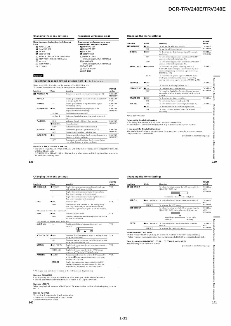
1-33
DCR-TRV240E/TRV340E
138
Changing the menu settings
English
Selecting the mode setting of each item z is the default setting.
Menu items differ depending on the position of the POWER switch.The screen shows only the items you can operate at the moment.
Icon/item
PROGRAM AE
P EFFECT
D EFFECT
FLASH MODE
FLASH LVL
N.S. LIGHT
AUTO SHTR
Mode
—
—
—
z ON
AUTO
AUTO
HIGH
z NORMAL
LOW
z ON
OFF
z ON
OFF
Meaning
To suit your specific shooting requirement (p. 65)
To add special effects like those in films or on the TVto images (p. 60, 82)
To add special effects using the various digitalfunctions (p. 62, 84)
To fire the flash (optional) regardless of thebrightness of the surroundings
The flash fires automatically.
To fire the flash before recording to reduce the red-eye
Makes the flash level higher than normal.
Normal setting
Makes the flash level lower than normal.
To use the NightShot Light function (p. 37)
To cancel the NightShot Light function
To automatically activate the electronic shutter whenshooting in bright conditions
To not automatically activate the electronic shuttereven when shooting in bright conditions
POWER switch
CAMERAMEMORY
CAMERAVCR
CAMERAVCR
CAMERAMEMORY
CAMERAMEMORY
CAMERAMEMORY
Menu items are displayed as the followingicons:
MANUAL SETCAMERA SETVCR SETLCD/VF SETMEMORY SET (DCR-TRV340E only)PRINT SET (DCR-TRV340E only)TAPE SETSETUP MENUOTHERS
CAMERAMEMORY
Notes on FLASH MODE and FLASH LVL•You cannot adjust FLASH MODE or FLASH LVL if the flash (optional) is not compatible with FLASH
MODE or FLASH LVL.•FLASH MODE and FLASH LVL are displayed only when an external flash (optional) is connected to
the intelligent accessory shoe.
Изменение установок меню
Опции меню отображаются в видеприведенных ниже пиктограмм:
MANUAL SETCAMERA SETVCR SETLCD/VF SETMEMORY SET(только модель DCR-TRV340E)PRINT SET(только модель DCR-TRV340E)TAPE SETSETUP MENUOTHERS
139
Cu
stom
izing
Yo
ur C
amco
rder В
ып
ол
не
ни
е и
нд
ив
ид
уа
ль
ны
х у
ста
но
во
к н
а В
аш
ей
ви
де
ок
ам
ер
е
Changing the menu settings
Icon/item
SELFTIMER*
D ZOOM
PHOTO REC*
16:9WIDE
STEADYSHOT
FRAME REC
INT. REC
* DCR-TRV340E only
Notes on the SteadyShot function•The SteadyShot function will not correct excessive camera-shake.•Attachment of a conversion lens (optional) may influence the SteadyShot function.
If you cancel the SteadyShot functionThe SteadyShot off indicator appears on the screen. Your camcorder prevents excessivecompensation for camera-shake.
(continued on the following page)
POWER switch
CAMERAMEMORY
CAMERA
CAMERA
CAMERAMEMORY
CAMERA
CAMERA
Mode
z OFF
ON
z OFF
50×
700×
z MEMORY
TAPE
z OFF
ON
z ON
OFF
z OFF
ON
ON
z OFF
SET
Meaning
To not use the self-timer function
To use the self-timer function
To deactivate the digital zoom. Up to 25× zoom isperformed.
To activate the digital zoom. More than 25× to 50×zoom is performed digitally (p. 31).
To activate the digital zoom. More than 25× to 700×zoom is performed digitally (p. 31).
To record still images on “Memory Stick”s inCAMERA mode while you are in the standby modeor recording moving pictures on tape by pressingPHOTO (p. 168)
To record still images on tape in CAMERA modewhile you are in the standby mode or recordingmoving pictures on tape by pressing PHOTO (p. 51)
—
To record a 16:9 wide picture (p. 55)
To compensate for camera-shake
To cancel the SteadyShot function. Natural picturesare produced when shooting a stationary object witha tripod.
To deactivate the frame recording
To activate the frame recording (p. 73)
To activate the interval recording function (p. 71)
To deactivate the interval recording function
To set INTERVAL and REC TIME for intervalrecording
CAMERAMEMORY
140
Changing the menu settings
Icon/item
HiFi SOUND
TBC*
TBC stands for “Time Base Corrector”.
DNR*
DNR stands for “Digital Noise Reduction”.
AUDIO MIX
A/V t DV OUT
NTSC PB
PB MODE
* When you play back tapes recorded in the Hi8/standard 8 system only
Notes on AUDIO MIX•When playing back a tape recorded in the 16-bit mode, you cannot adjust the balance.•You can adjust the balance only for tapes recorded in the Digital8 system.
Notes on NTSC PBWhen you play back a tape on a Multi System TV, select the best mode while viewing the picture onthe TV.
Note on PB MODEThe mode will return to the default setting when:– you remove the battery pack or power source.– you turn the POWER switch.
ST1 ST2
Mode
z STEREO
1
2
z ON
OFF
z ON
OFF
—
z OFF
ON
z ON PAL TV
NTSC 4.43
z AUTO
/
Meaning
To play back a stereo tape or dual sound track tapewith main and sub sound (p. 253)
To play back a stereo tape with the left sound or adual sound track tape with main sound
To play back a stereo tape with the right sound or adual sound track tape with sub sound
To correct jitter
To not correct jitter. Set TBC to OFF when playingback a tape on which you have dubbed over andrecorded the signal of a TV game or similar machine.
To reduce picture noise
To reduce a conspicuous afterimage when the picturehas a lot of movement
To adjust the balance between the stereo 1 andstereo 2
To output digital images and sound in analog formatusing your camcorder
To output analog images and sound in digital formatusing your camcorder (p. 114)
To playback a tape recorded on your camcorder on aPAL system TV
To playback a tape recorded in the NTSC coloursystem on a TV with the NTSC 4.43 mode
To automatically select the system (Hi8/standard 8or Digital8 ) that was used to record on the tape,and play back the tape
To play back a tape that was recorded in the Hi8/standard 8 system when your camcorder does notautomatically distinguish the recording system
POWER switch
VCR
VCR
VCR
VCR
VCR
VCR
VCR
141
Cu
stom
izing
Yo
ur C
amco
rder В
ып
ол
не
ни
е и
нд
ив
ид
уа
ль
ны
х у
ста
но
во
к н
а В
аш
ей
ви
де
ок
ам
ер
е
Changing the menu settings
Icon/item
LCD BRIGHT
LCD B. L.
LCD COLOUR
VF B.L.
Notes on LCD B.L. and VF B.L.•When you select BRIGHT, battery life is reduced by about 10 percent during recording.•When you use power sources other than the battery pack, BRIGHT is automatically selected.
Even if you adjust LCD BRIGHT, LCD B.L., LCD COLOUR and/or VF B.L.The recorded picture will not be affected.
(continued on the following page)
To get low-intensity
To get high-intensity
Mode
—
z BRT NORMAL
BRIGHT
—
z BRT NORMAL
BRIGHT
POWER switch
CAMERAVCRMEMORY
CAMERAVCRMEMORY
CAMERAVCRMEMORY
CAMERAVCRMEMORY
To lightenTo darken
Meaning
To adjust the brightness on the LCD screen with theSEL/PUSH EXEC dial.
To set the brightness on the LCD screen to normal
To brighten the LCD screen
To adjust the colour on the LCD screen, turning theSEL/PUSH EXEC dial to adjust the following bar
To set the brightness on the viewfinder screen tonormal
To brighten the viewfinder screen

1-34
DCR-TRV240E/TRV340E
144
Changing the menu settings
Icon/item
REC MODE
AUDIO MODE
q REMAIN
Notes on the LP mode•When you record a tape in the LP mode on your camcorder, we recommend playing back the tape on
your camcorder. When you play back the tape on other camcorders or VCRs, noise may occur inpictures or sound.
•When you record in the LP mode, we recommend using a Sony cassette so that you can get the mostout of your camcorder.
•When you record in the SP and LP modes on one tape or you record some scenes in the LP mode, theplayback picture may be distorted or the time code may not be written properly between scenes.
Note on AUDIO MODEWhen playing back a tape recorded in the 16-bit mode, you cannot adjust the balance in AUDIO MIX.
*To dub a tape to another VCRYou cannot select AUDIO MODE for tapes recorded in the Digital8 system. You, however, can selectAUDIO MODE when you dub tapes recorded in the Hi8/standard 8 system to another VCR using thei.LINK cable.
Mode
z SP
LP
z 12BIT
16BIT
z AUTO
ON
Meaning
To record in the SP (Standard Play) mode
To increase the recording time to 1.5 times the SPmode
To record in the 12-bit mode (two stereo sounds)
To record in the 16-bit mode (one stereo sound withhigh quality)
To display the remaining tape bar:• For about eight seconds after your camcorder is
turned on and calculates the remaining amount oftape
• For about eight seconds after a cassette is insertedand your camcorder calculates the remainingamount of tape
• For about eight seconds after N is pressed in VCRmode
• For about eight seconds after DISPLAY is pressedto display the screen indicators
• For the period of tape rewinding, forwarding orpicture search in VCR mode
To always display the remaining tape bar
POWER switch
CAMERAVCR
CAMERAVCR*
CAMERAVCR
145
Cu
stom
izing
Yo
ur C
amco
rder В
ып
ол
не
ни
е и
нд
ив
ид
уа
ль
ны
х у
ста
но
во
к н
а В
аш
ей
ви
де
ок
ам
ер
е
Changing the menu settings
Icon/item
CLOCK SET
USB STREAM
LTR SIZE
LANGUAGE
DEMO MODE
1) European models only2) The other country’s models only
Notes on DEMO MODE•You cannot select DEMO MODE when a cassette is inserted in your camcorder.•The DEMO MODE default setting is STBY (Standby), and the demonstration starts about 10 minutes
after you have set the POWER switch to CAMERA without a cassette inserted.To cancel the demonstration, insert a cassette, set the POWER switch to other than CAMERA, or setDEMO MODE to OFF. To set to STBY (Standby) again, leave the DEMO MODE at ON in the menusettings, turn the POWER switch to OFF (CHG), and return the POWER switch to CAMERA.
•When NIGHTSHOT is set to ON, the “NIGHTSHOT” indicator appears on the screen and you cannotselect DEMO MODE in the menu settings.
(continued on the following page)
Mode
—
z OFF
ON
z NORMAL
2×
z ENGLISH
FRANÇAIS1)
ESPAÑOL1)
PORTUGUÊS1)
DEUTSCH1)
ITALIANO1)
EΛΛHNIKA1)
[SIMP]2)
[COMP]2)
z ON
OFF
Meaning
To set the date or time (p. 24)
To deactivate the USB Streaming function
To activate the USB Streaming function
To display selected menu items in normal size
To display selected menu items at twice the normalsize
To display the following information indicators inEnglish: REC, STBY, min, CAPTURE, END SEARCHand VOL, etc.
To display the information indicators in French
To display the information indicators in Spanish
To display the information indicators in Portuguese
To display the information indicators in German
To display the information indicators in Italian
To display the information indicators in Greek
To display the information indicators in SimplifiedChinese
To display the information indicators in TraditionalChinese
To make the demonstration appear
To cancel the demonstration mode
POWER switch
CAMERAMEMORY
CAMERAVCRMEMORY
CAMERAVCRMEMORY
CAMERA
CAMERAVCR
142
Changing the menu settings
Icon/item
* STILL SET
PIC MODE
QUALITY
FLD/FRAME
MOVIE SET
IMAGESIZE
REMAIN
PRINT MARK
PROTECT
SLIDE SHOW
PHOTO SAVE
FILE NO.
Mode
z SINGLE
MULTI SCRN
z FINE
STANDARD
z FIELD
FRAME
z 320 × 240
160 × 112
z AUTO
ON
ON
z OFF
ON
z OFF
—
—
z SERIES
RESET
Meaning
To not record continuously
To record nine images continuously, display theimages on a single page divided into nine boxes.
To record still images in the fine image quality mode(p. 162)
To record still images in the standard image qualitymode
To record moving subjects correcting jitter (p. 167)
To record stopping subjects in high quality
To record moving pictures at 320 × 240 size (p. 164)
To record moving pictures at 160 × 112 size
To display the remaining capacity of the “MemoryStick” in the following cases:• For five seconds after inserting a “Memory Stick”
into your camcorder• When the capacity of the “Memory Stick” is less
than one minute in MEMORY mode• For five seconds after completing a moving picture
recording
To always display the remaining capacity of the“Memory Stick”
To write a print mark on recorded still images youwant to print out later (p. 227)
To cancel print marks on still images
To protect selected images against accidental erasure(p. 222)
To not protect images
To play back images in a continuous loop (p. 220)
To copy still images on tape onto “Memory Stick”(p. 185)
To assign numbers to file in sequence even if the“Memory Stick” is changed
To reset the file numbering each time the “MemoryStick” is changed
POWER switch
MEMORY
VCRMEMORY
MEMORY
VCRMEMORY
VCRMEMORY
VCRMEMORY
VCRMEMORY
MEMORY
VCR
VCRMEMORY
* DCR-TRV340E only
143
Cu
stom
izing
Yo
ur C
amco
rder В
ып
ол
нен
ие и
нд
ив
ид
уаль
ны
х устано
во
к н
а Ваш
ей в
ид
еок
амер
е
Changing the menu settings
Icon/item
* DELETE ALL
FORMAT
* 9PIC PRINT
DATE/TIME
Mode
z RETURN
OK
z RETURN
OK
z RETURN
SAME
MULTI
MARKED
z OFF
DATE
DAY&TIME
Meaning
To cancel deleting all images
To delete all unprotected images
To cancel formatting
To format an inserted “Memory Stick”1. Select FORMAT with the SEL/PUSH EXEL dial,
then press the dial.2. Select OK with the SEL/PUSH EXEC dial, then
press the dial.3. After EXECUTE appears, press the SEL/PUSH
EXEC dial. FORMATTING flashes duringformatting. COMPLETE appears when formattingis finished.
To cancel prints of split screens
To make prints of the same split screen (p. 229)
To make prints of different split screens
To make prints of images with print marks inrecording order
To make prints without the recording date and time
To make prints with the recording date
To make prints with the recording date and time(p. 229)
POWER switch
MEMORY
MEMORY
MEMORY
MEMORY
Notes on formatting*•Supplied “Memory Stick”s have been formatted at factory. Formatting “Memory Stick”s on your
camcorder is not required.•Do not turn the POWER switch or press any button while the display shows FORMATTING.•You cannot format the “Memory Stick” if the write-protect tab on the “Memory Stick” is set to LOCK.•Format the “Memory Stick” when “ FORMAT ERROR” is displayed.
Formatting erases all information on the “Memory Stick”*Check the contents of the “Memory Stick” before formatting.• Formatting erases sample images on the “Memory Stick.”• Formatting erases protected image data on the “Memory Stick.”
Note on PRINT SET*9PIC PRINT and DATE/TIME are displayed only when an external printer (optional) is connected tothe intelligent accessory shoe.
* DCR-TRV340E only(continued on the following page)
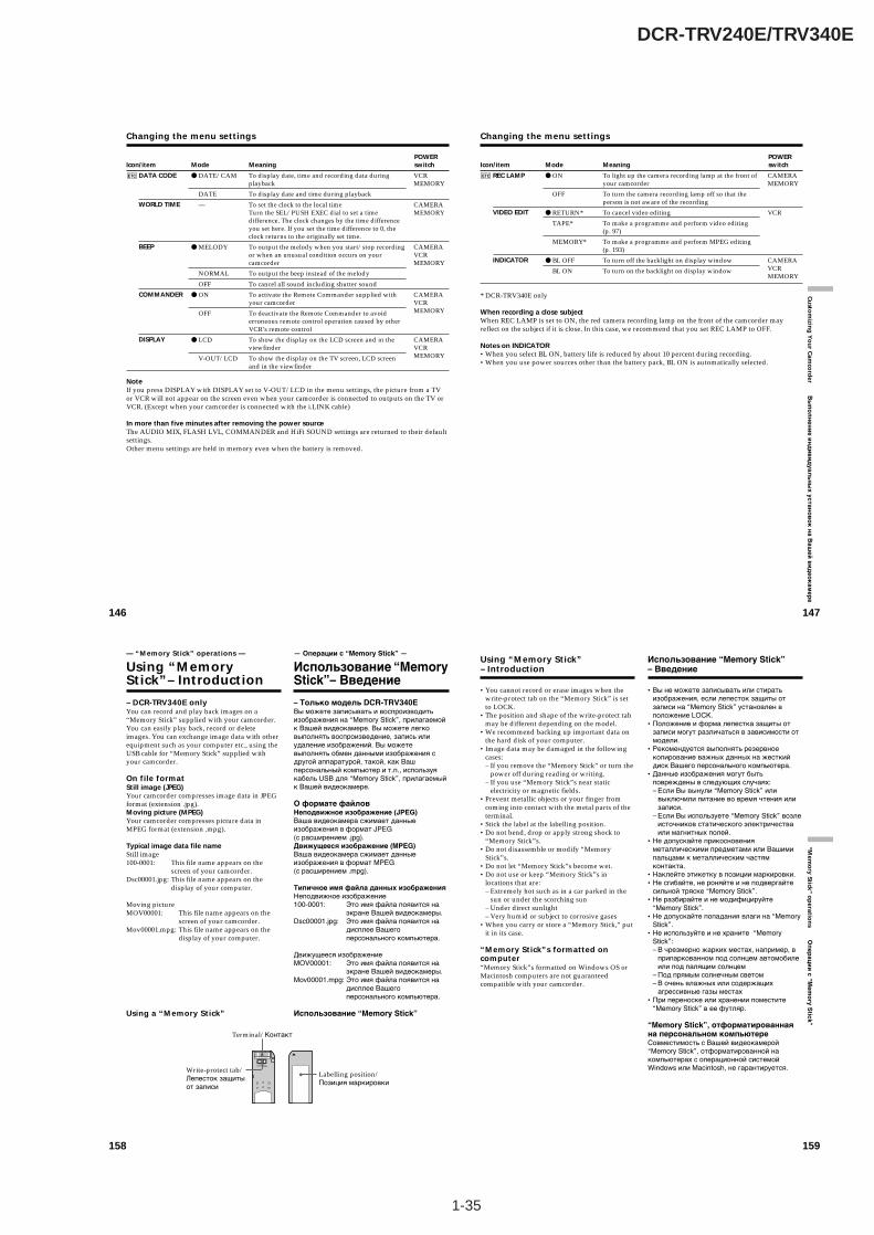
1-35
DCR-TRV240E/TRV340E
146
Icon/item
DATA CODE
WORLD TIME
BEEP
COMMANDER
DISPLAY
Mode
z DATE/CAM
DATE
—
z MELODY
NORMAL
OFF
z ON
OFF
z LCD
V-OUT/LCD
Meaning
To display date, time and recording data duringplayback
To display date and time during playback
To set the clock to the local timeTurn the SEL/PUSH EXEC dial to set a timedifference. The clock changes by the time differenceyou set here. If you set the time difference to 0, theclock returns to the originally set time.
To output the melody when you start/stop recordingor when an unusual condition occurs on yourcamcorder
To output the beep instead of the melody
To cancel all sound including shutter sound
To activate the Remote Commander supplied withyour camcorder
To deactivate the Remote Commander to avoiderroneous remote control operation caused by otherVCR’s remote control
To show the display on the LCD screen and in theviewfinder
To show the display on the TV screen, LCD screenand in the viewfinder
POWER switch
VCRMEMORY
CAMERAMEMORY
CAMERAVCRMEMORY
CAMERAVCRMEMORY
CAMERAVCRMEMORY
NoteIf you press DISPLAY with DISPLAY set to V-OUT/LCD in the menu settings, the picture from a TVor VCR will not appear on the screen even when your camcorder is connected to outputs on the TV orVCR. (Except when your camcorder is connected with the i.LINK cable)
In more than five minutes after removing the power sourceThe AUDIO MIX, FLASH LVL, COMMANDER and HiFi SOUND settings are returned to their defaultsettings.Other menu settings are held in memory even when the battery is removed.
Changing the menu settings
147
Cu
stom
izing
Yo
ur C
amco
rder В
ып
ол
не
ни
е и
нд
ив
ид
уа
ль
ны
х у
ста
но
во
к н
а В
аш
ей
ви
де
ок
ам
ер
е
Changing the menu settings
Icon/item
REC LAMP
VIDEO EDIT
INDICATOR
Mode
z ON
OFF
z RETURN*
TAPE*
MEMORY*
z BL OFF
BL ON
Meaning
To light up the camera recording lamp at the front ofyour camcorder
To turn the camera recording lamp off so that theperson is not aware of the recording
To cancel video editing
To make a programme and perform video editing(p. 97)
To make a programme and perform MPEG editing(p. 193)
To turn off the backlight on display window
To turn on the backlight on display window
POWER switch
CAMERAMEMORY
VCR
CAMERAVCRMEMORY
* DCR-TRV340E only
When recording a close subjectWhen REC LAMP is set to ON, the red camera recording lamp on the front of the camcorder mayreflect on the subject if it is close. In this case, we recommend that you set REC LAMP to OFF.
Notes on INDICATOR•When you select BL ON, battery life is reduced by about 10 percent during recording.•When you use power sources other than the battery pack, BL ON is automatically selected.
158
– DCR-TRV340E onlyYou can record and play back images on a“Memory Stick” supplied with your camcorder.You can easily play back, record or deleteimages. You can exchange image data with otherequipment such as your computer etc., using theUSB cable for “Memory Stick” supplied withyour camcorder.
On file formatStill image (JPEG)Your camcorder compresses image data in JPEGformat (extension .jpg).Moving picture (MPEG)Your camcorder compresses picture data inMPEG format (extension .mpg).
Typical image data file nameStill image100-0001: This file name appears on the
screen of your camcorder.Dsc00001.jpg: This file name appears on the
display of your computer.
Moving pictureMOV00001: This file name appears on the
screen of your camcorder.Mov00001.mpg: This file name appears on the
display of your computer.
Using a “Memory Stick”
— “Memory Stick” operations —
Using “MemoryStick”– Introduction
Write-protect tab/Лепесток защитыот записи
Labelling position/Позиция маркировки
Terminal/Контакт
— Операции с “Memory Stick” —
Использование “MemoryStick”– Bведение
– Только модель DCR-TRV340EВы можете записывать и воспроизводитьизображения на “Memory Stick”, прилагаемойк Вашей видеокамере. Вы можете легковыполнять воспроизведение, запись илиудаление изображений. Вы можетевыполнять обмен данными изображения сдругой аппаратурой, такой, как Вашперсональный компьютер и т.п., используякабель USB для “Memory Stick”, прилагаемыйк Вашей видеокамере.
О формате файловНеподвижное изображение (JPEG)Ваша видеокамера сжимает данныеизображения в формат JPEG(с расширением .jpg).Движущееся изображение (MPEG)Ваша видеокамера сжимает данныеизображения в формат MPEG(с расширением .mpg).
Типичное имя файла данных изображенияНеподвижное изображение100-0001: Это имя файла появится на
экране Вашей видеокамеры.Dsc00001.jpg: Это имя файла появится на
дисплее Вашегоперсонального компьютера.
Движущееся изображениеMOV00001: Это имя файла появится на
экране Вашей видеокамеры.Mov00001.mpg: Это имя файла появится на
дисплее Вашегоперсонального компьютера.
Использование “Memory Stick”
159
“Mem
ory Stick ” o
peratio
ns О
пе
ра
ци
и с
“Me
mo
ry S
tick
”
Using “Memory Stick”– Introduction
•You cannot record or erase images when thewrite-protect tab on the “Memory Stick” is setto LOCK.
•The position and shape of the write-protect tabmay be different depending on the model.
•We recommend backing up important data onthe hard disk of your computer.
•Image data may be damaged in the followingcases:– If you remove the “Memory Stick” or turn the
power off during reading or writing.– If you use “Memory Stick”s near static
electricity or magnetic fields.•Prevent metallic objects or your finger from
coming into contact with the metal parts of theterminal.
•Stick the label at the labelling position.•Do not bend, drop or apply strong shock to
“Memory Stick”s.•Do not disassemble or modify “Memory
Stick”s.•Do not let “Memory Stick”s become wet.•Do not use or keep “Memory Stick”s in
locations that are:– Extremely hot such as in a car parked in the
sun or under the scorching sun– Under direct sunlight– Very humid or subject to corrosive gases
•When you carry or store a “Memory Stick,” putit in its case.
“Memory Stick”s formatted oncomputer“Memory Stick”s formatted on Windows OS orMacintosh computers are not guaranteedcompatible with your camcorder.
Использование “Memory Stick”– Введение
•Вы не можете записывать или стиратьизображения, если лепесток защиты отзаписи на “Memory Stick” установлен вположение LOCK.
•Положение и форма лепестка защиты отзаписи могут различаться в зависимости отмодели.
•Рекомендуется выполнять резервноекопирование важных данных на жесткийдиск Вашего персонального компьютера.
•Данные изображения могут бытьповреждены в следующих случаях:– Если Вы вынули “Memory Stick” или
выключили питание во время чтения илизаписи.
– Если Вы используете “Memory Stick” возлеисточников статического электричестваили магнитных полей.
•Не допускайте прикосновенияметаллическими предметами или Вашимипальцами к металлическим частямконтакта.
•Наклейте этикетку в позиции маркировки.•Не сгибайте, не роняйте и не подвергайте
сильной тряске “Memory Stick”.•Не разбирайте и не модифицируйте
“Memory Stick”.•Не допускайте попадания влаги на “Memory
Stick”.•Не используйте и не храните “Memory
Stick”:– В чрезмерно жарких местах, например, в
припаркованном под солнцем автомобилеили под палящим солнцем
– Под прямым солнечным светом– В очень влажных или содержащих
агрессивные газы местах•При переноске или хранении поместите
“Memory Stick” в ее футляр.
“Memory Stick”, отформатированнаяна персональном компьютереСовместимость с Вашей видеокамерой“Memory Stick”, отформатированной накомпьютерах с операционной системойWindows или Macintosh, не гарантируется.
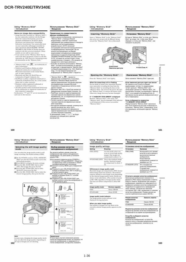
1-36
DCR-TRV240E/TRV340E
162
Selecting the still image qualitymode
You can select the image quality mode in stillimage recording. The default setting is FINE.
(1) Set the POWER switch to VCR or MEMORY.Make sure that the LOCK switch is set to theleft (unlock) position.
(2) Press MENU to display the menu settings.(3) Turn the SEL/PUSH EXEC dial to select
STILL SET in , then press the dial.(4) Turn the SEL/PUSH EXEC dial to select
QUALITY, then press the dial.(5) Turn the SEL/PUSH EXEC dial to select the
desired image quality, then press the dial.
NoteIn some cases, changing the image quality modemay not affect the image quality, depending onthe type of images you are shooting.
Using “Memory Stick”– Introduction
1
2
3
4
5MENU
CAMERA
MEMORY
VCROFF(CHG
)
POWER
MEMORY SET STILL SET PIC MODE QUALITY FLD/FRAME RETURN
[MENU] : END
SINGLE
MEMORY SET STILL SET PIC MODE QUALITY FLD/FRAME RETURN
[MENU] : END
FINE STANDARD
REMAIN 40
MEMORY SET STILL SET PIC MODE QUALITY FLD/FRAME RETURN
[MENU] : END
STANDARD
REMAIN 60
Выбор режима качестванеподвижного изображения
Вы можете выбрать режим качестваизображения при записи неподвижногоизображения. По умолчанию установленрежим FINE.
(1) Установите переключатель POWER вположение VCR или MEMORY. Убедитесь,что фиксатор LOCK установлен в левом(незафиксированном) положении.
(2) Нажмите кнопку MENU для отображенияменю.
(3) Поверните диск SEL/PUSH EXEC длявыбора установки STILL SET в опции ,а затем нажмите диск.
(4) Поверните диск SEL/PUSH EXEC длявыбора установки QUALITY, а затемнажмите диск.
(5) Поверните диск SEL/PUSH EXEC длявыбора нужного качества изображения, азатем нажмите диск.
ПримечаниеВ некоторых случаях изменение режимакачества изображения может не повлиять накачество изображения, в зависимости оттипов изображений, которые Вы снимаете.
Использование “Memory Stick”– Введение
163
“Mem
ory Stick ” o
peratio
ns О
пе
ра
ци
и с
“Me
mo
ry S
tick
”
Image quality settings
Setting Meaning
FINE (FINE) Use this mode when youwant to record high qualityimages. Fine images arecompressed to about 1/6.
STANDARD (STD) This is the standard imagequality. Standard imagesare compressed to about 1/10.
Differences in image quality modeRecorded images are compressed in JPEG formatbefore being stored into memory. The memorycapacity allotted to each image varies dependingon the selected image quality mode. Details areshown in the table below. (The number of pixelsis 640 × 480, regardless of image quality mode.The data size before compression is about 600KB.)
Image quality mode Memory capacity
FINE About 100 KB
STANDARD About 60 KB
Image quality mode indicatorThe image quality mode indicator is notdisplayed during playback.
When you select image qualityThe number of images you can shoot in thecurrently selected image quality appears on thescreen.
Using “Memory Stick”– Introduction
Установки качества изображения
Установка Значение
FINE (FINE) Используйте этот режим,если Вы хотите записатьвысококачественныеизображения.Качественныеизображения сжимаютсяпримерно до 1/6.
STANDARD (STD) Это стандартноекачество изображения.Стандартныеизображения сжимаютсяпримерно до 1/10.
Отличия в режиме качества изображенияЗаписанные изображения сжимаются вформате JPEG перед сохранением в памяти.Емкость памяти, выделенная для каждогоизображения, изменяется в зависимости отвыбранного режима качества изображения.Подробности содержатся в приведеннойниже таблице. (Количество пикселейсоставляет 640 × 480, независимо от режимакачества изображения. Размер данных досжатия приблизительно равен 600 Кб.)
Режим качества Емкость памятиизображения
FINE Около 100 Кб
STANDARD Около 60 Кб
Индикатор режима качества изображенияИндикатор режима качества изображения неотображается во время воспроизведения.
Когда Вы выбираете качествоизображенияКоличество изображений, которое Выможете снять в текущем выбранном режимекачества изображения, появляется наэкране.
Использование “Memory Stick”– Введение
160
Using “Memory Stick”– Introduction
Notes on image data compatibility•Image data files recorded on “Memory Stick”s
by your camcorder conform with the DesignRules for Camera File Systems universalstandard established by the JEITA (JapanElectronics and Information TechnologyIndustries Association). You cannot play backon your camcorder still images recorded onother equipment (DCR-TRV890E/TRV900/TRV900E or DSC-D700/D770) that does notconform with this universal standard. (Thesemodels are not sold in some areas.)
•If you cannot use the “Memory Stick” that isused with other equipment, format it with thiscamcorder (p. 143). However, formatting erasesall information on the “Memory Stick.”
•“Memory Stick” and are trademarks ofSony Corporation.
•Windows and Windows Media are eitherregistered trademarks or trademarks ofMicrosoft Corporation in the United Statesand/or other countries.
•Macintosh and Mac OS, QuickTime aretrademarks of Apple Computer, Inc.
•RealPlayer is either a registered trademark ortrademark of RealNetworks, Inc. in the UnitedStates and/or other countries.
•Pentium is either registered trademark ortrademark of Intel Corporation.
•All other product names mentioned herein maybe the trademarks or registered trademarks oftheir respective companies.
Furthermore, “™” and “®” are not mentioned ineach case in this manual.
Использование “Memory Stick”– Введение
Примечания по совместимостиданных изображения•Файлы данных изображения, записанные на
“Memory Stick” с помощью Вашейвидеокамеры, отвечают проектнымтребованиям для универсального стандартафайловых систем видеокамеры,разработанного JEITA (японскойассоциацией электронной промышленностии информационных технологий). Вы неможете воспроизводить на Вашейвидеокамере неподвижные изображения,записанные на другой аппаратуре (DCR-TRV890E/TRV900/TRV900E или DSC-D700/D770), которые не соответствуют этомууниверсальному стандарту. (Эти модели непродаются в некоторых регионах.)
•Если Вы не можете использовать “MemoryStick”, которая использовалась на другойаппаратуре, отформатируйте “Memory Stick”на Вашей видеокамере (стр. 153). Имейте ввиду, что при форматировании всяинформация на “Memory Stick” стирается.
•“Memory Stick” и являютсяфирменными знаками Sony Corporation.
•Windows и Windows Media являютсязарегистрированными торговыми маркамиили фирменными знаками MicrosoftCorporation в Соединенных Штатах и/илидругих странах.
•Macintosh, Mac OS и QuickTime являютсяфирменными знаками Apple Computer, Inc.
•RealPlayer является зарегистрированнойторговой маркой или фирменным знакомRealNetworks, Inc. в Соединенных Штатах и/или других странах.
•Pentium является зарегистрированнойторговой маркой или фирменным знакомIntel Corporation.
•Все другие названия изделий, упомянутые вданном руководстве, могут бытьфирменными знаками или официальнозарегистрированными торговыми маркамисоответствующих компаний.
В дальнейшем, знаки “ ” и “ ” не будутуказываться каждый раз в данномруководстве.
161
“Mem
ory Stick ” o
peratio
ns О
пер
аци
и с “M
emo
ry Stick”
Inserting “Memory Stick”
Insert a “Memory Stick” in the “Memory Stick”slot as far as it can go with the b mark facingtoward the “Memory Stick” slot as illustrated.
Ejecting the “Memory Stick”
Press the “Memory Stick” once lightly.
When the access lamp is lit or flashingDo not shake or knock your camcorder becauseyour camcorder is reading the data from the“Memory Stick” or recording the data on the“Memory Stick”. Do not turn the power off, ejectthe “Memory Stick” or remove the battery pack.Otherwise, image data may become damaged.
If “ MEMORY STICK ERROR” is displayedReinsert “Memory Stick” a few times. The“Memory Stick” may be damaged if the indicatoris still displayed. If this occurs, use another“Memory Stick.”
Using “Memory Stick”– Introduction
Установка “Memory Stick”
Вставьте “Memory Stick” в отсек для “MemoryStick” до упора, так, чтобы знак b былобращен к отсеку для “Memory Stick”, какпоказано на рисунке.
Извлечение “Memory Stick”
Легко нажмите “Memory Stick” один раз.
Если лампочка доступа горит или мигаетНе трясите и не стучите по Вашейвидеокамере, потому что видеокамерачитает данные с “Memory Stick” илизаписывает данные на “Memory Stick”. Невыключайте питание, не извлекайте “MemoryStick” и не снимайте батарейный блок. Впротивном случае данные изображения могутбыть повреждены.
Если отображается индикатор“ MEMORY STICK ERROR”Переустановите “Memory Stick” несколькораз. Если индикатор все еще отображается,возможно, “Memory Stick” повреждена. Еслиэто произошло, используйте другую “MemoryStick”.
Использование “Memory Stick”– Введение
b mark/Знак bAccess lamp/Лампочка доступа
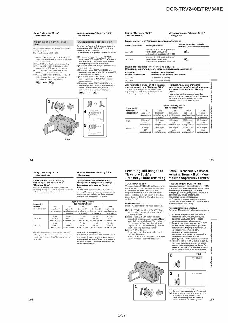
1-37
DCR-TRV240E/TRV340E
164
Selecting the moving imagesize
You can select either 320 × 240 or 160 × 112 formoving image sizes.The default setting is 320 × 240.
(1) Set the POWER switch to VCR or MEMORY.Make sure that the LOCK switch is set to theleft (unlock) position.
(2) Press MENU to display the menu settings.(3) Turn the SEL/PUSH EXEC dial to select
MOVIE SET in , then press the dial.(4) Turn the SEL/PUSH EXEC dial to select
IMAGESIZE, then press the dial.(5) Turn the SEL/PUSH EXEC dial to select the
desired image size, then press the dial.The indicator changes as follows:
320 160
4
5
1
CAMERA
MEMORY
VCROFF(CHG
)
POWER
320
40sec
MEMORY SET MOVIE SET IMAGESIZE REMAIN RETURN
[MENU] : END
320 × 240160 × 112
REMAIN
2 min
MEMORY SET MOVIE SET IMAGESIZE REMAIN RETURN
[MENU] : END
160 × 112
REMAIN
MENU
Using “Memory Stick”– Introduction
Выбор размера изображения
Вы может выбрать любой из двух размеровизображения 320 × 240 или 160 × 112 длядвижущихся изображений.По умолчанию выбирается размер 320 × 240.
(1) Установите переключатель POWER вположение VCR или MEMORY. Убедитесь,что фиксатор LOCK установлен в левом(незафиксированном) положении.
(2) Нажмите кнопку MENU для отображенияустановок меню.
(3) Поверните диск SEL/PUSH EXEC длявыбора установки MOVIE SET в опции ,а затем нажмите диск.
(4) Поверните диск SEL/PUSH EXEC длявыбора установки IMAGESIZE, а затемнажмите диск.
(5) Поверните диск SEL/PUSH EXEC длявыбора нужного размера изображения, азатем нажмите диск. Индикаторизменяется в следующем порядке:
320 160
Использование “Memory Stick”– Введение
165
“Mem
ory Stick ” o
peratio
ns О
пер
аци
и с “M
emo
ry Stick”
Image size settings/Установки размера изображения
Setting/Установка Meaning/ЗначениеIndicator (Recording/Playback)/Индикатор (Запись/Воспроизведение)
Records 320 × 240 moving pictures./
320320 × 240 Записывает движущиесяизображения размером 320 × 240.
Records 160 × 112 moving pictures./
160160 × 112 Записывает движущиесяизображения размером 160 × 112.
Maximum recording time of moving pictures/Максимальная длительность записи движущихся изображений
Image size/ Maximum recording time/Размер изображения Максимальная длительность записи
320 × 240 15 seconds/15 секунд
160 × 112 60 seconds/60 секунд
Approximate number of still imagesyou can record on a “Memory Stick”The number of images you can record variesdepending on which image quality you selectand the complexity of the subject.
Using “Memory Stick”– Introduction
Приблизительное количествонеподвижных изображений, которыеВы можете записать на “MemoryStick”Количество изображений, которые Выможете записать, изменяется в зависимостиот выбранных Вами режима качестваизображения и сложности объекта.
Использование “Memory Stick”– Введение
Type of “Memory Stick”s/Image quality/ Тип “Memory Stick”
Качество 8MB 16MB 32MB 64MB 128MBизображения (supplied)/ (optional)/ (optional)/ (optional)/ (optional)/
(прилагается) (приобретается (приобретается (приобретается (приобретаетсяотдельно) отдельно) отдельно) отдельно)
FINE80 images/ 160 images/ 325 images/ 650 images/ 1310 images/
80 160 325 650 1310изображений изображений изображений изображений изображений
STANDARD120 images/ 240 images/ 485 images/ 980 images/ 1970 images/
120 240 485 980 1970изображений изображений изображений изображений изображений
166
Approximate time of movingpictures you can record on a“Memory Stick”The time of moving pictures you can recordvaries depending on which image size you selectand the complexity of the subject.
The table above shows approximate number ofstill images and times of moving pictures you canrecord on a “Memory Stick” formatted on yourcamcorder.
Using “Memory Stick”– Introduction
Приблизительная длительностьдвижущихся изображений, которыеВы можете записать на “MemoryStick”Длительность движущихся изображений,которые Вы можете записать, изменяется взависимости от выбранных Вами размераизображения и сложности объекта.
В таблицах выше приведеноприблизительное количество неподвижныхизображений и длительность движущихсяизображений, которые Вы можете записатьна “Memory Stick”, отформатированный наВашей видеокамере.
Использование “Memory Stick”– Введение
Type of “Memory Stick”s/Image size/ Тип “Memory Stick”
Размер 8MB 16MB 32MB 64MB 128MBизображения (supplied)/ (optional)/ (optional)/ (optional)/ (optional)/
(прилагается) (приобретается (приобретается (приобретается (приобретаетсяотдельно) отдельно) отдельно) отдельно)
5 min. 10 min. 21 min. 42 min. 85 min.160 × 112 20 sec./ 40 sec./ 20 sec./ 40 sec./ 20 sec.
5 мин 20 сек. 10 мин 40 сек. 21 мин 20 сек. 42 мин 40 сек. 85 мин 20 сек.
1 min. 2 min. 5 min. 10 min. 21 min.320 × 240 20 sec./ 40 sec./ 20 sec./ 40 sec./ 20 sec./
1 мин 20 сек. 2 мин 40 сек. 5 мин 20 сек. 10 мин 40 сек. 21 мин 20 сек.
167
“Mem
ory Stick ” o
peratio
ns О
пе
ра
ци
и с
“Me
mo
ry S
tick
”
– DCR-TRV340E onlyYou can select the FIELD or FRAME mode in stillimage recording. Your camcorder compensatesfor camera-shake when recording movingsubjects in the FIELD mode. Your camcorderrecords still images in high quality in the FRAMEmode. Select the FIELD or FRAME in the menusettings (p. 136).
Before operationInsert a “Memory Stick” into your camcorder.
(1) Set the POWER switch to MEMORY. Makesure that the LOCK switch is set to the left(unlock) position.
(2) Keep pressing PHOTO lightly until thedesired still image appears. The green z markstops flashing, then lights up. The brightnessof the image and focus are adjusted, beingtargeted for the middle of the image and arefixed. Recording does not start yet.
(3) Press PHOTO deeper.Recording is complete when the bar scrollindicator disappears.The image when you pressed PHOTO deeperwill be recorded on the “Memory Stick.”
[a]: Number of recorded images/Количество записанных изображений
[b]: Approximate number of images that canbe recorded on the “Memory Stick”./Количество изображений, которыеможно записать на “Memory Stick”
3
21 / 12STD
STD
PH
OTO
PH
OTO
1
CAMERA
MEMORY
VCROFF(CHG
)
POWER
[a][b]
Recording still images on“Memory Stick”s– Memory Photo recording
– Только модель DCR-TRV340EВы можете выбрать режим FIELD или FRAMEпри записи неподвижных изображений. Вашавидеокамера компенсирует дрожаниекамеры при съемке движущихся объектов врежиме FIELD. Ваша видеокамерапроизводит запись неподвижныхизображений высокого качества в режимеFRAME. Выберите режим FIELD или FRAME вустановках меню (стр. 136).
Перед выполнением операцииВставьте “Memory Stick” в Вашу видеокамеру.
(1) Установите переключатель POWER вположение MEMORY. Убедитесь, чтофиксатор LOCK установлен в левом(незафиксированном) положении.
(2) Держите слегка нажатой кнопку PHOTO,пока не появится нужное изображение.Зеленая метка z прекращает мигать, азатем высвечивается. Яркостьизображения и фокусировкарегулируются, исходя из их значений всередине изображения, а затемфиксируются. Запись пока не начинается.
(3) Нажмите кнопку PHOTO сильнее. Записьсчитается завершенной, если исчезнетиндикатор полосы прокрутки. Когда Вынажмите кнопку PHOTO сильнее, изобра-жение будет записано на “Memory Stick”.
Запись неподвижных изобра-жений на “Memory Stick” – Фото-съемка с сохранением в памяти
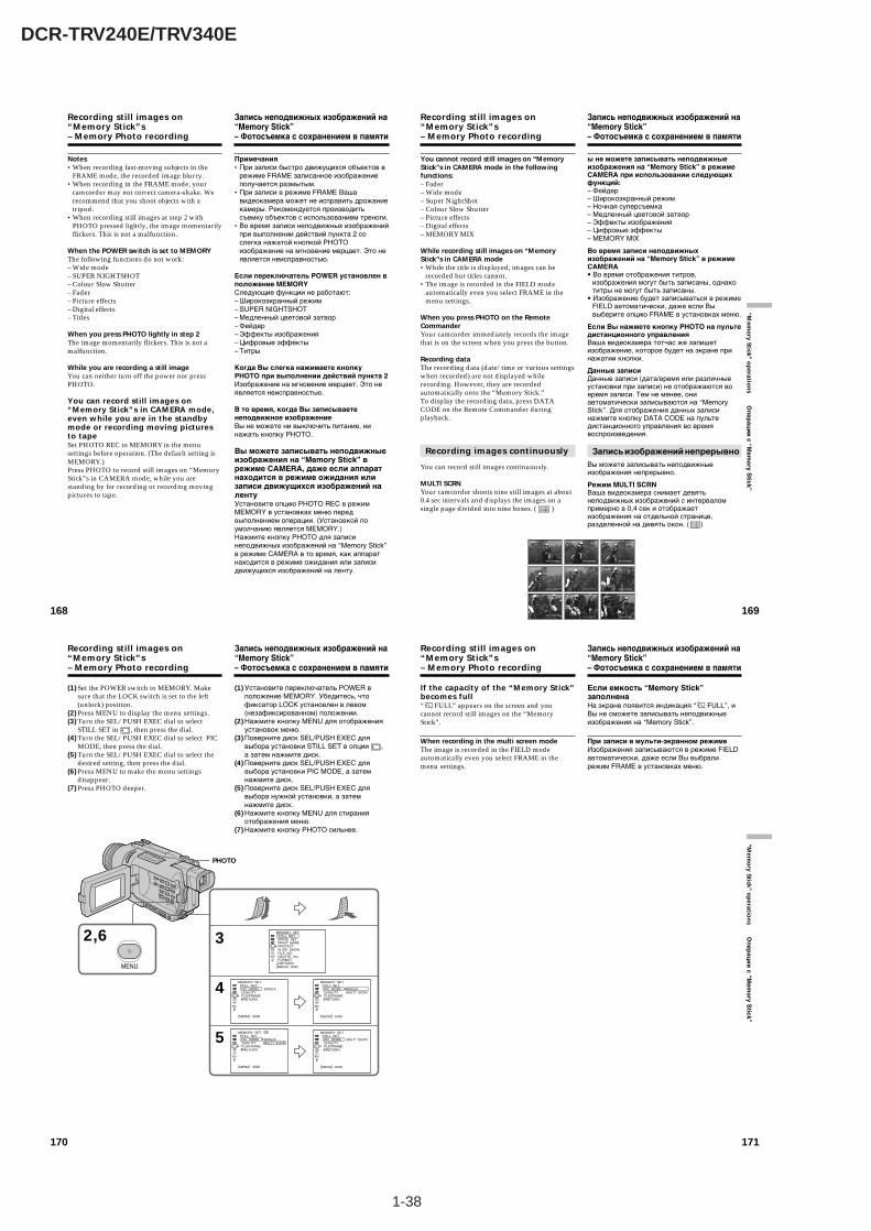
1-38
DCR-TRV240E/TRV340E
170
(1) Set the POWER switch to MEMORY. Makesure that the LOCK switch is set to the left(unlock) position.
(2) Press MENU to display the menu settings.(3) Turn the SEL/PUSH EXEC dial to select
STILL SET in , then press the dial.(4) Turn the SEL/PUSH EXEC dial to select PIC
MODE, then press the dial.(5) Turn the SEL/PUSH EXEC dial to select the
desired setting, then press the dial.(6) Press MENU to make the menu settings
disappear.(7) Press PHOTO deeper.
Recording still images on“Memory Stick”s– Memory Photo recording
2,6 3
4
5
MENU
MEMORY SET STILL SET PIC MODE QUALITY FLD/FRAME RETURN
[MENU] : END
SINGLEMULTI SCRN
MEMORY SET STILL SET MOVIE SET PRINT MARK PROTECT SLIDE SHOW FILE NO. DELETE ALL FORMAT RETURN[MENU] : END
MEMORY SET STILL SET PIC MODE QUALITY FLD/FRAME RETURN
[MENU] : END
SINGLE
MEMORY SET STILL SET PIC MODE QUALITY FLD/FRAME RETURN
[MENU] : END
SINGLEMULTI SCRN
MEMORY SET STILL SET PIC MODE QUALITY FLD/FRAME RETURN
[MENU] : END
MULTI SCRN
PHOTO
Запись неподвижных изображений на“Memory Stick”– Фотосъемка с сохранением в памяти
(1) Установите переключатель POWER вположение MEMORY. Убедитесь, чтофиксатор LOCK установлен в левом(незафиксированном) положении.
(2) Нажмите кнопку MENU для отображенияустановок меню.
(3) Поверните диск SEL/PUSH EXEC длявыбора установки STILL SET в опции ,а затем нажмите диск.
(4) Поверните диск SEL/PUSH EXEC длявыбора установки PIC MODE, а затемнажмите диск.
(5) Поверните диск SEL/PUSH EXEC длявыбора нужной установки, а затемнажмите диск.
(6) Нажмите кнопку MENU для стиранияотображения меню.
(7) Нажмите кнопку PHOTO сильнее.
171
“Mem
ory Stick ” o
peratio
ns О
пе
ра
ци
и с
“Me
mo
ry S
tick
”
If the capacity of the “Memory Stick”becomes full“ FULL” appears on the screen and youcannot record still images on the “MemoryStick”.
When recording in the multi screen modeThe image is recorded in the FIELD modeautomatically even you select FRAME in themenu settings.
Recording still images on“Memory Stick”s– Memory Photo recording
Запись неподвижных изображений на“Memory Stick”– Фотосъемка с сохранением в памяти
Если емкость “Memory Stick”заполненаНа экране появится индикация “ FULL”, иВы не сможете записывать неподвижныеизображения на “Memory Stick”.
При записи в мульти-экранном режимеИзображения записываются в режиме FIELDавтоматически, даже если Вы выбралирежим FRAME в установках меню.
168
Recording still images on“Memory Stick”s– Memory Photo recording
Notes•When recording fast-moving subjects in the
FRAME mode, the recorded image blurry.•When recording in the FRAME mode, your
camcorder may not correct camera-shake. Werecommend that you shoot objects with atripod.
•When recording still images at step 2 withPHOTO pressed lightly, the image momentarilyflickers. This is not a malfunction.
When the POWER switch is set to MEMORYThe following functions do not work:– Wide mode– SUPER NIGHTSHOT– Colour Slow Shutter– Fader– Picture effects– Digital effects– Titles
When you press PHOTO lightly in step 2The image momentarily flickers. This is not amalfunction.
While you are recording a still imageYou can neither turn off the power nor pressPHOTO.
You can record still images on“Memory Stick”s in CAMERA mode,even while you are in the standbymode or recording moving picturesto tapeSet PHOTO REC to MEMORY in the menusettings before operation. (The default setting isMEMORY.)Press PHOTO to record still images on “MemoryStick”s in CAMERA mode, while you arestanding by for recording or recording movingpictures to tape.
Запись неподвижных изображений на“Memory Stick”– Фотосъемка с сохранением в памяти
Примечания•При записи быстро движущихся объектов в
режиме FRAME записанное изображениеполучается размытым.
•При записи в режиме FRAME Вашавидеокамера может не исправить дрожаниекамеры. Рекомендуется производитьсъемку объектов с использованием треноги.
•Во время записи неподвижных изображенийпри выполнении действий пункта 2 сослегка нажатой кнопкой PHOTOизображение на мгновение мерцает. Это неявляется неисправностью.
Если переключатель POWER установлен вположение MEMORYСледующие функции не работают:– Широкоэкранный режим– SUPER NIGHTSHOT– Медленный цветовой затвор– Фейдер– Эффекты изображения– Цифровые эффекты– Титры
Когда Вы слегка нажимаете кнопкуPHOTO при выполнении действий пункта 2Изображение на мгновение мерцает. Это неявляется неисправностью.
В то время, когда Вы записываетенеподвижное изображениеВы не можете ни выключить питание, нинажать кнопку PHOTO.
Вы можете записывать неподвижныеизображения на “Memory Stick” врежиме СAMERA, даже если аппаратнаходится в режиме ожидания илизаписи движущихся изображений налентуУстановите опцию PHOTO REC в режимMEMORY в установках меню передвыполнением операции. (Установкой поумолчанию является MEMORY.)Нажмите кнопку PHOTO для записинеподвижных изображений на “Memory Stick”в режиме СAMERA в то время, как аппаратнаходится в режиме ожидания или записидвижущихся изображений на ленту.
169
“Mem
ory Stick ” o
peratio
ns О
пер
аци
и с “M
emo
ry Stick”
You cannot record still images on “MemoryStick”s in CAMERA mode in the followingfunctions:– Fader– Wide mode– Super NightShot– Colour Slow Shutter– Picture effects– Digital effects– MEMORY MIX
While recording still images on “MemoryStick”s in CAMERA mode•While the title is displayed, images can be
recorded but titles cannot.•The image is recorded in the FIELD mode
automatically even you select FRAME in themenu settings.
When you press PHOTO on the RemoteCommanderYour camcorder immediately records the imagethat is on the screen when you press the button.
Recording dataThe recording data (date/time or various settingswhen recorded) are not displayed whilerecording. However, they are recordedautomatically onto the “Memory Stick.”To display the recording data, press DATACODE on the Remote Commander duringplayback.
Recording images continuously
You can record still images continuously.
MULTI SCRNYour camcorder shoots nine still images at about0.4 sec intervals and displays the images on asingle page divided into nine boxes. ( )
Recording still images on“Memory Stick”s– Memory Photo recording
ы не можете записывать неподвижныеизображения на “Memory Stick” в режимеCAMERA при использовании следующихфункций:– Фейдер– Широкоэкранный режим– Ночная суперсъемка– Медленный цветовой затвор– Эффекты изображения– Цифровые эффекты– MEMORY MIX
Во время записи неподвижныхизображений на “Memory Stick” в режимеCAMERA• Во время отображения титров,
изображения могут быть записаны, однакотитры не могут быть записаны.
• Изображение будет записываться в режимеFIELD автоматически, даже если Вывыберите опцию FRAME в установках меню.
Если Вы нажмете кнопку PHOTO на пультедистанционного управленияВаша видеокамера тотчас же запишетизображение, которое будет на экране принажатии кнопки.
Данные записиДанные записи (дата/время или различныеустановки при записи) не отображаются вовремя записи. Тем не менее, ониавтоматически записываются на “MemoryStick”. Для отображения данных записинажмите кнопку DATA CODE на пультедистанционного управления во времявоспроизведения.
Запись изображений непрерывноВы можете записывать неподвижныеизображения непрерывно.
Режим MULTI SCRNВаша видеокамера снимает девятьнеподвижных изображений с интерваломпримерно в 0,4 сек и отображаетизображения на отдельной странице,разделенной на девять окон. ( )
Запись неподвижных изображений на“Memory Stick”– Фотосъемка с сохранением в памяти
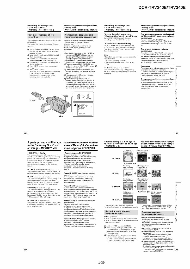
1-39
DCR-TRV240E/TRV340E
172
Self-timer memory photorecording
You can record images on “Memory Stick”s withthe self-timer.You can use the Remote Commander for thisoperation.
(1) Set the POWER switch to MEMORY. Makesure that the LOCK switch is set to the left(unlock) position.
(2) In the standby mode, press MENU to displaythe menu settings.
(3) Turn the SEL/PUSH EXEC dial to selectSELFTIMER in , then press the dial.
(4) Turn the SEL/PUSH EXEC dial to select ON,then press the dial.
(5) Press MENU to make the menu settingsdisappear.
(6) Press PHOTO deeper.Self-timer starts counting down from 10 witha beep. In the last two seconds of thecountdown, the beep gets faster, thenrecording starts automatically.
Recording still images on“Memory Stick”s– Memory Photo recording
4 CAMERA SET SELFTIMER D ZOOM STEADYSHOT RETURN
OFFON
[MENU] : END
PHOTO
MENU
PHOTO
Запись неподвижных изображений на“Memory Stick”– Фотосъемка с сохранением в памяти
Фотосъемка с сохранением впамяти по таймеру самозапуска
Вы можете записывать изображения на“Memory Stick” с помощью таймерасамозапуска.Для этой операции Вы можете такжеиспользовать пульт дистанционногоуправления.
(1) Установите переключатель POWER вположение MEMORY. Убедитесь, чтофиксатор LOCK установлен в левом(незафиксированном) положении.
(2) В режиме ожидания нажмите кнопкуMENU для отображения установок меню.
(3) Поверните диск SEL/PUSH EXEC длявыбора установки SELFTIMER в опции ,а затем нажмите диск.
(4) Поверните диск SEL/PUSH EXEC длявыбора установки ON, а затем нажмитедиск.
(5) Нажмите кнопку MENU для стиранияотображения меню.
(6) Нажмите кнопку PHOTO сильнее.Таймер самозапуска начнет обратныйотсчет от 10 с зуммерным сигналом. Впоследние 2 секунды обратного отсчетазуммерный сигнал будет звучать чаще, азатем автоматически начнется запись.
173
“Mem
ory Stick ” o
peratio
ns О
пер
аци
и с “M
emo
ry Stick”
Recording still images on“Memory Stick”s– Memory Photo recording
To record moving pictures on“Memory Stick”s with the self-timerPress START/STOP in step 6. To cancelrecording, press START/STOP again.
To cancel self-timer recordingSet SELFTIMER to OFF in the menu settingswhile your camcorder is in the standby mode.You cannot cancel self-timer recording withRemote Commander.
NoteThe self-timer recording mode is automaticallycancelled when:– Self-timer recording is finished.– The POWER switch is set to OFF (CHG) or
VCR.
To check the image to be recordedYou can check the image by lightly pressingPHOTO, then press it deeper to start self-timerrecording.
Запись неподвижных изображений на“Memory Stick”– Фотосъемка с сохранением в памяти
Для записи движущихся изображенийна “Memory Stick” с помощью таймерасамозапускаНажмите кнопку START/STOP привыполнении действий пункта 6. Для отменызаписи нажмите кнопку START/STOP ещераз.
Для отмены записи по таймерусамозапускаУстановите опцию SELFTIMER в положениеOFF в установках меню в то время, когдаВаша видеокамера находится в режимеожидания. Вы не можете отменить запись потаймеру самозапуска, используя пультдистанционного управления.
ПримечаниеРежим записи по таймеру самозапуска будетавтоматически отменен в случаях:– Окончания записи по таймеру самозапуска.– Установки переключателя POWER в
положение OFF (CHG) или VCR.
Для проверки изображения, которое будетзаписыватьсяВы можете проверить изображение, нажавслегка кнопку PHOTO, а затем нажав еесильнее для пуска записи по таймерусамозапуска.
174
Superimposing a still imagein the “Memory Stick” onan image – MEMORY MIX
– DCR-TRV340E onlyYou can superimpose a still image you haverecorded on the “Memory Stick” on the movingpicture you are recording. You can record thesuperimposed images on a tape or a “MemoryStick”. (However, you can record onlysuperimposed still images on the “MemoryStick”.)
M. CHROM (memory chroma key)You can swap a blue area of a still image such asan illustration or a frame with a moving picture.
M. LUMI (memory luminance key)You can swap a brighter area of a still image suchas a handwritten illustration or title with amoving picture. Record a title on the “MemoryStick” before a trip or event for convenience.
C. CHROM (camera chroma key)You can superimpose a moving picture on a stillimage such as an image can be used asbackground. Shoot the subject against a bluebackground. The blue area of the moving imagewill be swapped with a still image.
M. OVERLAP* (memory overlap)You can make a moving picture fade in on top ofa still image recorded on the “Memory Stick” asthe overlap function.
Наложение неподвижного изобра-жения в “Memory Stick” на изобра-жение – функция MEMORY MIX
– Только модель DCR-TRV340EВы можете наложить неподвижноеизображение, записанное на “Memory Stick”,поверх записываемого движущегосяизображения. Вы можете записыватьналоженные изображения на ленту или на“Memory Stick”. (Однако, Вы можетезаписывать только наложенныенеподвижные изображения на “MemoryStick”.)
Режим M. CHROM (цветовая рирпроекцияпамяти)Вы можете менять местами синюю частьнеподвижного изображения, например,иллюстрации или кадра, с движущимсяизображением.
Режим M. LUMI (яркость памяти)Вы можете менять местами более яркуючасть неподвижного изображения, например,выполненной от руки иллюстрации или титра,с движущимся изображением. Запишите титрна “Memory Stick” перед путешествием иликаким-либо событием для удобства.
Режим C. CHROM (цветовая рирпроекциявидеокамеры)Вы можете наложить движущеесяизображение поверх неподвижногоизображения, например, изображения,которое может служить фоном. Выполнитесъемку объекта на синем фоне. Синяя частьдвижущегося изображения поменяетсяместами с неподвижным изображением.
Режим M. OVERLAP* (перекрытие памяти)Вы можете сделать плавный вводдвижущегося изображения поверхнеподвижного изображения, записанного на“Memory Stick”, как функцию перекрытия.
175
“Mem
ory Stick ” o
peratio
ns О
пе
ра
ци
и с
“Me
mo
ry S
tick
”
* The superimposed image using Memoryoverlap function can be recorded on tapes only.
Recording superimposedimages on a tape
Before operation•Insert a tape for recording into your camcorder.•Insert a “Memory Stick” is recorded still images
into your camcorder.
(1) Set the POWER switch to CAMERA.(2) In the standby mode, press MEMORY MIX.
The last recorded or last composed imageappears on the lower part of the screen as athumbnail image.
(3) Press MEMORY+/– to select the still imageyou want to superimpose.To see the previous image, press MEMORY –.To see the next image, press MEMORY+.
Superimposing a still image inthe “Memory Stick” on an image– MEMORY MIX
* Наложенные с использованием функцииперекрытия памяти изображения могутбыть записаны только на лентах.
Запись наложенныхизображений на ленту
Перед выполнением операции•Установите ленту для записи в Вашу
видеокамеру.•Установите “Memory Stick” с записанными
неподвижными изображениями в Вашувидеокамеру.
(1) Установите переключатель POWER вположение CAMERA.
(2) Нажмите кнопку MEMORY MIX в режимеожидания.Последнее записанное или последнеескомпонованное неподвижноеизображение появится в нижней частиэкрана в виде крохотного изображения.
(3) Нажмите кнопку MEMORY+/– для выборанеподвижного изображения, которое Выхотите наложить.Для просмотра предыдущего изображениянажмите кнопку MEMORY –.Для просмотра следующего изображениянажмите кнопку MEMORY+.
Наложение неподвижного изобра-жения в “Memory Stick” на изобра-жение – Функция MEMORY MIX
M. OVERLAP*
Still image/ Moving picture/Неподвижное Движущеесяизображение изображение
C. CHROM
Still image/ Moving picture/Неподвижное Движущеесяизображение изображение
Blue/Синий фон
M. LUMI
Still image/ Moving picture/Неподвижное Движущеесяизображение изображение
M. CHROM
Still image/ Moving picture/Неподвижное Движущеесяизображение изображение
Blue/Синий фон

1-40
DCR-TRV240E/TRV340E
178
Superimposing a still image inthe “Memory Stick” on an image– MEMORY MIX
Recording superimposedimages on a “Memory Stick” asa still image
Before operationInsert a “Memory Stick” is recorded still imagesinto your camcorder.
(1) Set the POWER switch to MEMORY. Makesure that the LOCK switch is set to the left(unlock) position.
(2) Press MEMORY MIX.The last recorded or last composed imageappears on the lower part of the screen as athumbnail image.
(3) Press MEMORY+/– to select the still imageyou want to superimpose.To see the previous image, press MEMORY –.To see the next image, press MEMORY+.
(4) Turn the SEL/PUSH EXEC dial to select thedesired mode.The mode changes as follows:M. CHROM y M. LUMI y C. CHROM
(5) Press the SEL/PUSH EXEC dial.The still image is superimposed on themoving picture.
(6) Turn the SEL/PUSH EXEC dial to adjust theeffect.
M. CHROM – The colour (blue) scheme ofthe area in the still imagewhich is to be swapped witha moving picture
M. LUMI – The colour (bright) schemeof the area in the still imagewhich is to be swapped witha moving picture
C. CHROM – The colour (blue) scheme ofthe area in the movingpicture which is to beswapped with a still image
The fewer bars there are on the screen, thestronger the effect becomes.
(7) Press PHOTO deeper to start recording.The image displayed on the screen will berecorded on a “Memory Stick.” Recording iscomplete when the bar scroll indicatordisappears.
Наложение неподвижного изобра-жения в “Memory Stick” на изобра-жение – Функция MEMORY MIX
Запись наложенныхизображений на “Memory Stick”как неподвижных изображений
Перед выполнением операцииУстановите “Memory Stick” с записанныминеподвижными изображениями в Вашувидеокамеру.
(1) Установите переключатель POWER вположение MEMORY. Убедитесь, чтофиксатор LOCK установлен в левом(незафиксированном) положении.
(2) Нажмите кнопку MEMORY MIX.Последнее записанное или последнеескомпонованное неподвижноеизображение появится в нижней частиэкрана в виде крохотного изображения.
(3) Нажмите кнопку MEMORY+/– для выборанеподвижного изображения, которое Выхотите наложить.Для просмотра предыдущего изображениянажмите кнопку MEMORY –.Для просмотра следующего изображениянажмите кнопку MEMORY+.
(4) Поверните диск SEL/PUSH EXEC длявыбора нужного режима.Режим будет изменяться следующимобразом:M.CHROM y M.LUMI y C.CHROM
(5) Нажмите диск SEL/PUSH EXEC.Неподвижное изображение будетналожено на подвижное изображение.
(6) Поверните диск SEL/PUSH EXEC длярегулировки эффекта.
M. CHROM – Цветовая гамма (синяя)участка в неподвижномизображении, которыйбудет заменен надвижущееся изображение
M. LUMI – Цветовая гамма (яркая)участка в неподвижномизображении, которыйбудет заменен надвижущееся изображение
C. CHROM – Цветовая гамма (синяя)участка в движущемсяизображении, котороебудет заменено нанеподвижное изображение
Чем меньше полос на экране, тем сильнееэффект.
(7) Нажмите кнопку PHOTO сильнее дляначала записи. Отображаемое на экранеизображение будет записано на “MemoryStick”. Запись считается завершенной, еслиисчезнет индикатор полосы прокрутки. 179
“Mem
ory Stick ” o
peratio
ns О
пе
ра
ци
и с
“Me
mo
ry S
tick
”
Superimposing a still image inthe “Memory Stick” on an image– MEMORY MIX
2
4
5
6
M. CHROM
M. LUMI
M. LUMI
M. LUMI
I I I ¥ ¥ ¥ ¥
I ¥ ¥ ¥ ¥ ¥ ¥
100–0021
100–0021
3
100–0021
100–0021
MEMORY MIX
Still image/Неподвижноеизображение
To change the still image tosuperimposeDo either of the following:– Press MEMORY+/– before step 7.– Press the SEL/PUSH EXEC dial before step 7,
and repeat the procedure from step 4.
To change the mode settingPress the SEL/PUSH EXEC dial before step 7,and repeat the procedure from step 4.
To cancel MEMORY MIXPress MEMORY MIX.
Notes•You cannot use the MEMORY MIX function for
moving pictures recorded on “Memory Stick”s.•When the overlapping still image has a large
amount of white, the thumbnail image of thepicture may not be clear.
Image data modified on your computer orshot with other equipmentYou may not be able to play modified imagesback with your camcorder.
During recordingYou cannot change the mode setting.
Наложение неподвижного изобра-жения в “Memory Stick” на изобра-жение – Функция MEMORY MIX
Чтобы изменить неподвижноеизображение для наложенияВыполните любое из следующих действий:– Нажмите кнопку MEMORY+/– перед
выполнением действий пункта 7.– Нажмите диск SEL/PUSH EXEC перед
выполнением действий пункта 7 иповторите процедуру, начиная с пункта 4.
Для изменения установки режимаНажмите диск SEL/PUSH EXEC передвыполнением действий пункта 7 и повторитепроцедуру с пункта 4.
Для отмены установки MEMORY MIXНажмите кнопку MEMORY MIX.
Примечания•Вы не можете использовать функцию
MEMORY MIX для движущихсяизображений, записанных на “MemoryStick”.
•Если перекрывающее неподвижноеизображение содержит большое количествобелого цвета, его крохотное изображениеможет быть нечетким.
Данные изображений, видоизмененных спомощью персональных компьютеров илиснятых с помощью другой аппаратурыВозможно, Вы не сможете воспроизвестимодифицированные изображения на Вашейвидеокамере.
Во время записиВы не можете изменить установку режима.
176
(4) Turn the SEL/PUSH EXEC dial to select thedesired mode.The mode changes as follows:M. CHROM y M. LUMI y C. CHROM yM. OVERLAP
(5) Press the SEL/PUSH EXEC dial.The still image is superimposed on themoving picture.
(6) Turn the SEL/PUSH EXEC dial to adjust theeffect.
M. CHROM – The colour (blue) scheme ofthe area in the still imagewhich is to be swapped witha moving picture
M. LUMI – The colour (bright) schemeof the area in the still imagewhich is to be swapped witha moving picture
C. CHROM – The colour (blue) scheme ofthe area in the movingpicture which is to beswapped with a still image
M. OVERLAP – No adjustment necessary
The fewer bars there are on the screen, thestronger the effect becomes.
(7) Press START/STOP to start recording.
Superimposing a still image inthe “Memory Stick” on an image– MEMORY MIX
2
4
5
6
M. CHROM
M. LUMI
M. LUMI
M. LUMI
I I I ¥ ¥ ¥ ¥
I ¥ ¥ ¥ ¥ ¥ ¥
100–0021
100–0021
3
100–0021
100–0021
MEMORY MIX
Still image/Неподвижноеизображение
Наложение неподвижного изобра-жения в “Memory Stick” на изобра-жение – Функция MEMORY MIX
(4) Поверните диск SEL/PUSH EXEC длявыбора нужного режима.Режим будет изменяться следующимобразом:M. CHROM y M. LUMI y C. CHROM yM. OVERLAP
(5) Нажмите диск SEL/PUSH EXEC.Неподвижное изображение будетналожено на подвижное изображение.
(6) Поверните диск SEL/PUSH EXEC длярегулировки эффекта.
M. CHROM – Цветовая гамма (синяя)участка в неподвижномизображении, которыйбудет заменен надвижущееся изображение
M. LUMI – Цветовая гамма (яркая)участка в неподвижномизображении, которыйбудет заменен надвижущееся изображение
C. CHROM – Цветовая гамма (синяя)участка в движущемсяизображении, котороебудет заменено нанеподвижное изображение
M. OVERLAP – Не требуется никакихрегулировок
Чем меньше полос на экране, тем сильнееэффект.
(7) Нажмите кнопку START/STOP для началазаписи.
177
“Mem
ory Stick ” o
peratio
ns О
пер
аци
и с “M
emo
ry Stick”
Superimposing a still image inthe “Memory Stick” on an image– MEMORY MIX
To change the still image tosuperimposeDo either of the following:– Press MEMORY+/– before step 7.– Press the SEL/PUSH EXEC dial before step 7,
and repeat the procedure from step 4.
To change the mode settingPress the SEL/PUSH EXEC dial before step 7,and repeat the procedure from step 4.
To cancel MEMORY MIXPress MEMORY MIX.
Notes•You cannot use the MEMORY MIX function for
moving pictures recorded on “Memory Stick”s.•When the overlapping still image has a large
amount of white, the thumbnail image of thepicture may not be clear.
Image data modified on your computer orshot with other equipmentYou may not be able to play modified imagesback with your camcorder.
When you select M. OVERLAPYou cannot change the still image or the modesetting.
During recordingYou cannot change the mode setting.
To record the superimposed image as a stillimagePress PHOTO deeper in step 7.
Images processed by MEMORY MIXYou cannot record the images on “MemoryStick”s in CAMERA mode.Record them in MEMORY mode. (p. 178)
Наложение неподвижного изобра-жения в “Memory Stick” на изобра-жение – Функция MEMORY MIX
Чтобы изменить неподвижноеизображение для наложенияВыполните любое из следующих действий:– Нажмите кнопку MEMORY+/– перед
выполнением действий пункта 7.– Нажмите диск SEL/PUSH EXEC перед
выполнением действий пункта 7 иповторите процедуру, начиная с пункта 4.
Для изменения установки режимаНажмите диск SEL/PUSH EXEC передвыполнением действий пункта 7 и повторитепроцедуру с пункта 4.
Для отмены установки MEMORY MIXНажмите кнопку MEMORY MIX.
Примечания•Вы не можете использовать функцию
MEMORY MIX для движущихсяизображений, записанных на “MemoryStick”.
•Если перекрывающее неподвижноеизображение содержит большое количествобелого цвета, его крохотное изображениеможет быть нечетким.
Данные изображений, видоизмененных спомощью персональных компьютеров илиснятых с помощью другой аппаратурыВозможно, Вы не сможете воспроизвестимодифицированные изображения на Вашейвидеокамере.
Если Вы выбираете режим M.OVERLAPВы не сможете изменить неподвижноеизображение или установку режима.
Во время записиВы не можете изменить установку режима.
Для записи наложенного изображения какнеподвижного изображенияНажмите кнопку PHOTO сильнее привыполнении действий пункта 7.
Изображение, обработанное с помощьюMEMORY MIXВы не можете записывать изображения на“Memory Stick” в режиме CAMERA.Запишите пункт в режиме MEMORY. (стр.178)
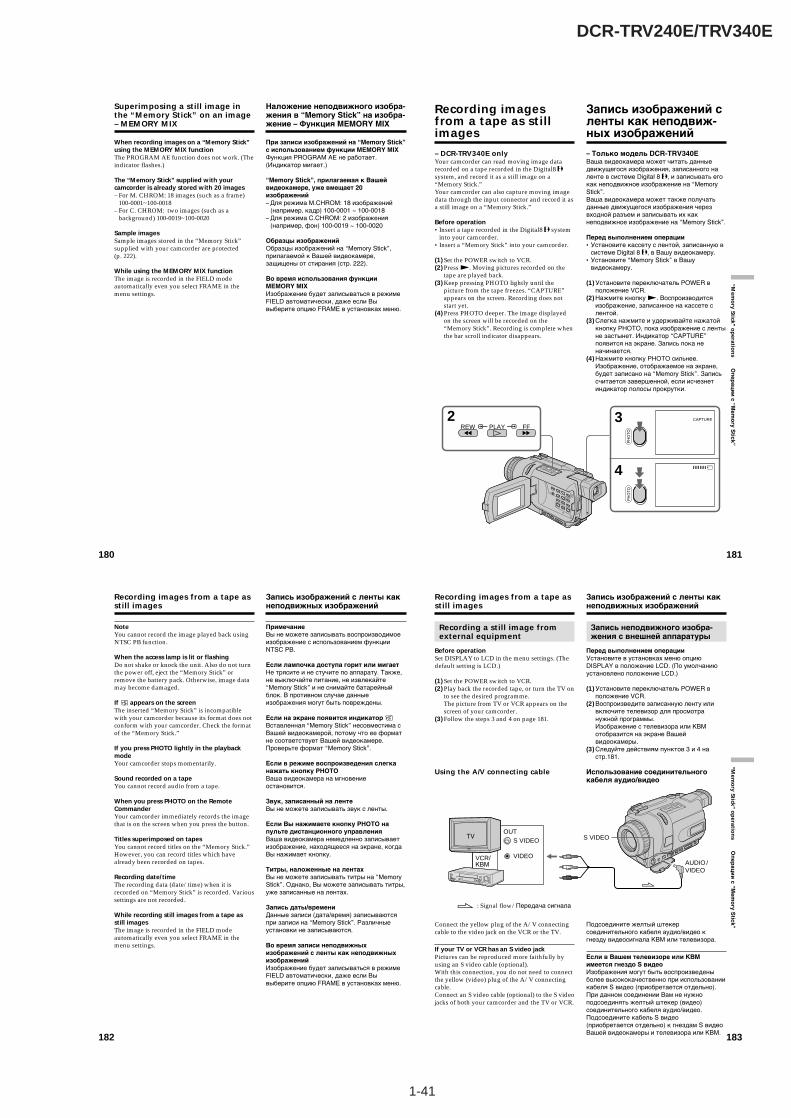
1-41
DCR-TRV240E/TRV340E
180
When recording images on a “Memory Stick”using the MEMORY MIX functionThe PROGRAM AE function does not work. (Theindicator flashes.)
The “Memory Stick” supplied with yourcamcorder is already stored with 20 images– For M. CHROM: 18 images (such as a frame)
100-0001~100-0018– For C. CHROM: two images (such as a
background) 100-0019~100-0020
Sample imagesSample images stored in the “Memory Stick”supplied with your camcorder are protected(p. 222).
While using the MEMORY MIX functionThe image is recorded in the FIELD modeautomatically even you select FRAME in themenu settings.
Superimposing a still image inthe “Memory Stick” on an image– MEMORY MIX
Наложение неподвижного изобра-жения в “Memory Stick” на изобра-жение – Функция MEMORY MIX
При записи изображений на “Memory Stick”с использованием функции MEMORY MIXФункция PROGRAM AE не работает.(Индикатор мигает.)
“Memory Stick”, прилагаемая к Вашейвидеокамере, уже вмещает 20изображений– Для режима M.CHROM: 18 изображений
(например, кадр) 100-0001 ~ 100-0018– Для режима C.CHROM: 2 изображения
(например, фон) 100-0019 ~ 100-0020
Образцы изображенийОбразцы изображений на “Memory Stick”,прилагаемой к Вашей видеокамере,защищены от стирания (стр. 222).
Во время использования функцииMEMORY MIXИзображение будет записываться в режимеFIELD автоматически, даже если Вывыберите опцию FRAME в установках меню.
181
“Mem
ory Stick ” o
peratio
ns О
пер
аци
и с “M
emo
ry Stick”
– DCR-TRV340E onlyYour camcorder can read moving image datarecorded on a tape recorded in the Digital8 system, and record it as a still image on a“Memory Stick.”Your camcorder can also capture moving imagedata through the input connector and record it asa still image on a “Memory Stick.”
Before operation•Insert a tape recorded in the Digital8 system
into your camcorder.•Insert a “Memory Stick” into your camcorder.
(1) Set the POWER switch to VCR.(2) Press N. Moving pictures recorded on the
tape are played back.(3) Keep pressing PHOTO lightly until the
picture from the tape freezes. “CAPTURE”appears on the screen. Recording does notstart yet.
(4) Press PHOTO deeper. The image displayedon the screen will be recorded on the“Memory Stick”. Recording is complete whenthe bar scroll indicator disappears.
2REW PLAY FF
4
3
PH
OTO
CAPTURE
PH
OTO
Recording imagesfrom a tape as stillimages
– Только модель DCR-TRV340EВаша видеокамера может читать данныедвижущегося изображения, записанного наленте в системе Digital 8 , и записывать егокак неподвижное изображение на “MemoryStick”.Ваша видеокамера может также получатьданные движущегося изображения черезвходной разъем и записывать их какнеподвижное изображение на “Memory Stick”.
Перед выполнением операции•Установите кассету с лентой, записанную в
системе Digital 8 , в Вашу видеокамеру.•Установите “Memory Stick” в Вашу
видеокамеру.
(1) Установите переключатель POWER вположение VCR.
(2) Нажмите кнопку N. Воспроизводитсяизображение, записанное на кассете слентой.
(3) Слегка нажмите и удерживайте нажатойкнопку PHOTO, пока изображение с лентыне застынет. Индикатор “CAPTURE”появится на экране. Запись пока неначинается.
(4) Нажмите кнопку PHOTO сильнее.Изображение, отображаемое на экране,будет записано на “Memory Stick”. Записьсчитается завершенной, если исчезнетиндикатор полосы прокрутки.
Запись изображений сленты как неподвиж-ных изображений
182
Recording images from a tape asstill images
NoteYou cannot record the image played back usingNTSC PB function.
When the access lamp is lit or flashingDo not shake or knock the unit. Also do not turnthe power off, eject the “Memory Stick” orremove the battery pack. Otherwise, image datamay become damaged.
If appears on the screenThe inserted “Memory Stick” is incompatiblewith your camcorder because its format does notconform with your camcorder. Check the formatof the “Memory Stick.”
If you press PHOTO lightly in the playbackmodeYour camcorder stops momentarily.
Sound recorded on a tapeYou cannot record audio from a tape.
When you press PHOTO on the RemoteCommanderYour camcorder immediately records the imagethat is on the screen when you press the button.
Titles superimposed on tapesYou cannot record titles on the “Memory Stick.”However, you can record titles which havealready been recorded on tapes.
Recording date/timeThe recording data (date/time) when it isrecorded on “Memory Stick” is recorded. Varioussettings are not recorded.
While recording still images from a tape asstill imagesThe image is recorded in the FIELD modeautomatically even you select FRAME in themenu settings.
Запись изображений с ленты какнеподвижных изображений
ПримечаниеВы не можете записывать воспроизводимоеизображение с использованием функцииNTSC PB.
Если лампочка доступа горит или мигаетНе трясите и не стучите по аппарату. Также,не выключайте питание, не извлекайте“Memory Stick” и не снимайте батарейныйблок. В противном случае данныеизображения могут быть повреждены.
Если на экране появится индикатор Вставленная “Memory Stick” несовместима сВашей видеокамерой, потому что ее форматне соответствует Вашей видеокамере.Проверьте формат “Memory Stick”.
Если в режиме воспроизведения слегканажать кнопку PHOTOВаша видеокамера на мгновениеостановится.
Звук, записанный на лентеВы не можете записывать звук с ленты.
Если Вы нажимаете кнопку PHOTO напульте дистанционного управленияВаша видеокамера немедленно записываетизображение, находящееся на экране, когдаВы нажимает кнопку.
Титры, наложенные на лентахВы не можете записывать титры на “MemoryStick”. Однако, Вы можете записывать титры,уже записанные на лентах.
Запись даты/времениДанные записи (дата/время) записываютсяпри записи на “Memory Stick”. Различныеустановки не записываются.
Во время записи неподвижныхизображений с ленты как неподвижныхизображенийИзображение будет записываться в режимеFIELD автоматически, даже если Вывыберите опцию FRAME в установках меню.
183
“Mem
ory Stick ” o
peratio
ns О
пе
ра
ци
и с
“Me
mo
ry S
tick
”
Recording a still image fromexternal equipment
Before operationSet DISPLAY to LCD in the menu settings. (Thedefault setting is LCD.)
(1) Set the POWER switch to VCR.(2) Play back the recorded tape, or turn the TV on
to see the desired programme.The picture from TV or VCR appears on thescreen of your camcorder.
(3) Follow the steps 3 and 4 on page 181.
Using the A/V connecting cable
Connect the yellow plug of the A/V connectingcable to the video jack on the VCR or the TV.
If your TV or VCR has an S video jackPictures can be reproduced more faithfully byusing an S video cable (optional).With this connection, you do not need to connectthe yellow (video) plug of the A/V connectingcable.Connect an S video cable (optional) to the S videojacks of both your camcorder and the TV or VCR.
Recording images from a tape asstill images
Запись неподвижного изобра-жения с внешней аппаратуры
Перед выполнением операцииУстановите в установках меню опциюDISPLAY в положение LCD. (По умолчаниюустановлено положение LCD.)
(1) Установите переключатель POWER вположение VCR.
(2) Воспроизведите записанную ленту иливключите телевизор для просмотранужной программы.Изображение с телевизора или КВМотобразится на экране Вашейвидеокамеры.
(3) Следуйте действиям пунктов 3 и 4 настр.181.
Использование соединительногокабеля аудио/видео
Подсоедините желтый штекерсоединительного кабеля аудио/видео кгнезду видеосигнала КВМ или телевизора.
Если в Вашем телевизоре или КВМимеется гнездо S видеоИзображения могут быть воспроизведеныболее высококачественно при использованиикабеля S видео (приобретается отдельно).При данном соединении Вам не нужноподсоединять желтый штекер (видео)соединительного кабеля аудио/видео.Подсоедините кабель S видео(приобретается отдельно) к гнездам S видеоВашей видеокамеры и телевизора или КВМ.
Запись изображений с ленты какнеподвижных изображений
: Signal flow/Передача сигнала
S VIDEO
VIDEO
OUTS VIDEO
AUDIO /VIDEO
VCR/КВМ
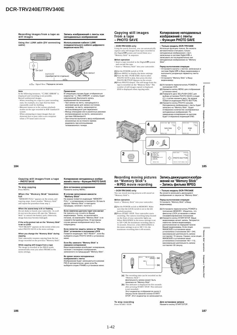
1-42
DCR-TRV240E/TRV340E
186
To stop copyingPress MENU.
When the “Memory Stick” becomesfull“MEMORY FULL” appears on the screen, andcopying stops. Insert another “Memory Stick”and repeat the procedure from step 2.
When the access lamp is lit or flashingDo not shake or knock your camcorder. As welldo not turn the power off, eject the “MemoryStick” or remove the battery pack. Otherwise,image data may become damaged.
If the write-protect tab on the “Memory Stick”is set to LOCK“NOT READY” appears on the screen when youselect PHOTO SAVE in the menu settings.
When you change the “Memory Stick” duringcopyingYour camcorder resumes copying from the lastimage recorded on the previous “Memory Stick”.
While copying still images from a tapeThe image is recorded in the FIELD modeautomatically even you select FRAME in themenu settings.
Copying still images from a tape– PHOTO SAVE
Для остановки копированияНажмите кнопку MENU.
В случае заполнения емкости“Memory Stick”На экране появится индикация “MEMORYFULL”, и копирование остановится. Вставьтедругую “Memory Stick” и повторитепроцедуру, начиная с пункта 2.
Если лампочка доступа горит или мигаетНе трясите и не стучите по Вашейвидеокамере. Также, не выключайтепитание, не извлекайте “Memory Stick” и неснимайте батарейный блок. В противномслучае данные изображения могут бытьповреждены.
Если лепесток защиты записи на “MemoryStick” установлен в положение LOCKПоявится индикация “NOT READY”, если Вывыберете опцию PHOTO SAVE в установкахменю.
Если Вы замените “Memory Stick” всередине копированияВаша видеокамера возобновит копирование,начиная с последнего изображения,записанного на предыдущей “Memory Stick”.
Во время записи неподвижныхизображений с лентыИзображение будет записываться в режимеFIELD автоматически, даже если Вывыберите опцию FRAME в установках меню.
Копирование неподвижных изобра-жений с ленты – Функция PHOTO SAVE
187
“Mem
ory Stick ” o
peratio
ns О
пер
аци
и с
“Me
mo
ry Stick”
– DCR-TRV340E onlyYou can record moving pictures with sound on“Memory Stick”s.
Before operationInsert a “Memory Stick” into your camcorder.
(1) Set the POWER switch to MEMORY. Makesure that the LOCK switch is set to the left(unlock) position.
(2) Press START/STOP. Your camcorder startsrecording. The camera recording lamp locatedon the front of your camcorder lights up.When IMAGESIZE in the menu settings is setto 320 × 240, the maximum recording time is15 seconds. However, when IMAGESIZE inthe menu settings is set to 160 × 112, themaximum recording time is 60 seconds.
To stop recordingPress START/STOP.
Recording moving pictureson “Memory Stick”s– MPEG movie recording
– Только модель DCR-TRV340EВы можете записывать движущиесяизображения со звуком на “Memory Stick”.
Перед выполнением операцииУстановите “Memory Stick” в Вашувидеокамеру.
(1) Установите переключатель POWER вположение MEMORY. Убедитесь, чтофиксатор LOCK установлен в левом(незафиксированном) положении.
(2) Нажмите кнопку START/STOP. Вашавидеокамера начнет запись. Загораетсялампочка записи видеокамеры,расположенная на передней панелиВашей видеокамеры. Если опцияIMAGESIZE в установках менюустановлена в положение 320 × 240,максимальная длительность записисоставляет 15 секунд. Однако, если опцияIMAGESIZE в установках менюустановлена в положение 160 × 112,максимальная длительность записисоставляет 60 секунд.
Для остановки записиНажмите кнопку START/STOP.
Запись движущихся изобра-жений на “Memory Stick”– Запись фильма MPEG
[a]: The recording time can be recorded on the“Memory Stick”/Длительность записи может бытьзаписана на “Memory Stick”
[b]: This indicator is displayed for five secondsafter pressing START/STOP. This indicatoris not recorded./Этот индикатор отображается около 5секунд после нажатия кнопки START/STOP. Этот индикатор не записывается.
2 320
BBB
50min REC 0:03[15sec] [a]
[b]
185
“Mem
ory Stick ” o
peratio
ns О
пер
аци
и с “M
emo
ry Stick”
Copying still imagesfrom a tape– PHOTO SAVE
– DCR-TRV340E onlyUsing the search function, you can automaticallycapture only still images from tapes recorded inthe Digital8 system and record them on a“Memory Stick” in sequence.
Before operation•Insert a tape recorded in the Digital8 system
and rewind the tape.•Insert a “Memory Stick” into your camcorder.
(1) Set the POWER switch to VCR.(2) Press MENU to display the menu settings.(3) Turn the SEL/PUSH EXEC dial to select
PHOTO SAVE in , then press the dial.PHOTO BUTTON appears on the screen.
(4) Press PHOTO deeper. The still image from thetape is recorded on the “Memory Stick.” Thenumber of still images copied is displayed.END is displayed when copying ends.
2
4
3MENU
PH
OTO SAV I NG
0
PHOTO SAVE
[MENU] : END
0:00:00:00
21/40 FINE
END4
PHOTO SAVE
[MENU] : END
0:30:00:00
25/40 FINE
MEMORY SET STILL SET MOVIE SET PRINT MARK PROTECT PHOTO SAVE FILE NO. RETURN
[MENU] : END
READY PHOTO BUTTON
PHOTO SAVE
[PHOTO] : START [MENU] : END
0:00:00:00
21/40 FINE
Копирование неподвижныхизображений с ленты– Функция PHOTO SAVE
– Только модель DCR-TRV340EИспользуя функцию поиска, Вы можетеавтоматически считывать тольконеподвижные изображения с лент,записанных в системе Digital 8 , изаписывать их последовательно какнеподвижные изображение на “MemoryStick”.
Перед выполнением операции•Установите кассету с лентой, записанную в
системе Digital 8 , в Вашу видеокамеру ивыполните ускоренную перемотку лентыназад.
•Установите “Memory Stick” в Вашувидеокамеру.
(1) Установите переключатель POWER вположение VCR.
(2) Нажмите кнопку MENU для отображенияустановок меню.
(3) Поверните диск SEL/PUSH EXEC длявыбора установки PHOTO SAVE в опции
, а затем нажмите диск. На экранепоявится индикация PHOTO BUTTON.
(4) Нажмите кнопку PHOTO сильнее.Неподвижное изображение с ленты будетзаписано на “Memory Stick”. Будетотображено количество скопированныхнеподвижных изображений. Позавершении копирования на дисплеебудет отображена индикация END.
184
Using the i.LINK cable (DV connectingcable)
NoteIn the following instances, “ REC ERROR” isdisplayed and recording is not possible.Record undistorted images.– When recording on a tape in a poor recording
state, for example, on a tape that has beenrepeatedly used for dubbing
– Between scenes or in the various playbackmodes on the tape recorded in Hi8/standard 8system
– When attempting to input images that aredistorted due to poor radio wave receptionwhen a TV tuner unit is in use
Recording images from a tape asstill images
Запись изображений с ленты какнеподвижных изображений
Использование кабеля i.LINK(соединительного кабеля цифровоговидеосигнала DV)
ПримечаниеВ следующих случаях будет отображатьсяиндикатор “ REC ERROR”, и запись будетневозможной. Выполните записьизображений без искажений.– При записи на ленту, находящуюся в
малопригодном для записи состоянии,например, на ленту, неоднократноиспользовавшуюся для перезаписи
– Между эпизодами или в различных режимахвоспроизведения на ленте, записанной всистеме Hi8/standard 8
– При попытке выполнить ввод изображений,искаженных из-за плохого приемарадиоволн при использованиителевизионного тюнера
DV
DV OUTDV IN/OUT
: Signal flow/Передача сигнала
(optional)/(приобретается отдельно)

1-43
DCR-TRV240E/TRV340E
188
Recording moving pictures on“Memory Stick”s– MPEG movie recording
NoteSound is recorded in monaural.
When the POWER switch is set to MEMORYThe following functions do not work:– Wide mode– SUPER NIGHTSHOT– Colour Slow Shutter– Fader– Picture effects– Digital effects– Titles
When the POWER switch is set to MEMORYThe angle of view is slightly larger comparedwith the angle of view in CAMERA mode.
When using an external flash (optional)Turn the power of the external flash off whenrecording moving pictures on “Memory Stick”s.Otherwise, the charging sound for the flash maybe recorded.
Recording date/timeThe date/time are not displayed while recording.However, they are automatically recorded ontothe “Memory Stick.”To display the recording date/time, press DATACODE on the Remote Commander duringplayback. Various settings cannot be recorded.
During recording on “Memory Stick”Do not eject the cassette tape from yourcamcorder. During ejecting the tape, sound is notrecorded on the “Memory Stick.”
Запись движущихся изображенийна “Memory Stick”– Запись фильма MPEG
ПримечаниеЗвук записывается в монофоническомрежиме.
Если переключатель POWER установлен вположение MEMORYСледующие функции не работают:– Широкоэкранный режим– SUPER NIGHTSHOT– Медленный цветовой затвор– Фейдер– Эффекты изображения– Цифровые эффекты– Титры
Если переключатель POWER установлен вположение MEMORYУгол охвата изображения будет немногобольше, чем угол охвата в режиме CAMERA.
При использовании внешней вспышки(приобретается отдельно)Отключите питание внешней вспышки призаписи движущихся изображений на “MemoryStick”. В противном случае может бытьзаписан звук зарядки вспышки.
Запись даты/времениДата/время не отображаются во времязаписи. Тем не менее, они автоматическизаписываются на “Memory Stick”.Для отображения данных записи нажмитекнопку DATA CODE на пультедистанционного управления во времявоспроизведения. Различные установки немогут быть записаны.
Во время записи на “Memory Stick”Не извлекайте кассету с лентой из Вашейвидеокамеры. Во время извлечения кассетызвук не записывается на “Memory Stick”.
189
“Mem
ory Stick ” o
peratio
ns О
пер
аци
и с “M
emo
ry Stick”
– DCR-TRV340E onlyYour camcorder can read moving picture datarecorded on tapes and record it as a movingpicture on a “Memory Stick.” Your camcordercan also capture moving picture data through theinput connector and record it as a moving pictureon a “Memory Stick.”
Before operation•Insert a recorded tape into your camcorder.•Insert a “Memory Stick” into your camcorder.
(1) Set the POWER switch to VCR.(2) Press N. The picture recorded on the tape is
played back.And press X at the scene where you want tostart recording from.
(3) Press START/STOP on your camcorder.When IMAGESIZE in the menu settings is setto 320 × 240, the maximum recording time is15 seconds. However, when IMAGESIZE inthe menu settings is set to 160 × 112, themaximum recording time is 60 seconds.
To stop recordingPress START/STOP or x.
Recording picturesfrom a tape asmoving pictures
– Только модель DCR-TRV340EВаша видеокамера может читать данныедвижущегося изображения, записанные наленте, и записывать их как движущеесяизображение на “Memory Stick”. Вашавидеокамера может получать также данныедвижущегося изображения через входнойразъем и записывать их как движущеесяизображение на “Memory Stick”.
Перед выполнением операции•Установите записанную кассету с лентой в
Вашу видеокамеру.•Установите “Memory Stick” в Вашу
видеокамеру.
(1) Установите переключатель POWER вположение VCR.
(2) Нажмите кнопку N. Воспроизводитсяизображение, записанное на кассете слентой.Нажмите также кнопку X на Вашейвидеокамере на эпизоде, с которого Выхотите начать запись.
(3) Нажмите кнопку START/STOP на Вашейвидеокамере. Если опция IMAGESIZE вустановках меню установлена вположение 320 × 240, максимальнаядлительность записи составляет 15секунд. Однако, если опция IMAGESIZE вустановках меню установлена вположение 160 × 112, максимальнаядлительность записи составляет 60секунд.
Для остановки записиНажмите кнопку START/STOP или x.
Запись изображений сленты как движущихсяизображений
32320
BBB
N 0:15:42:43REC0:03 [15sec]
50minPAUSEPLAY
[a]: The recording time can be recorded on the“Memory Stick.”/Длительность записи может бытьзаписана на “Memory Stick”
[b]: This indicator is displayed for five secondsafter pressing START/STOP. This indicator isnot recorded./Этот индикатор отображается около 5секунд после нажатия кнопки START/STOP. Этот индикатор не записывается.
[a]
[b]
190
Notes•Sound recorded in 48 kHz is converted to 32
kHz sound when recording pictures from atape to “Memory Stick”s.
•Sound recorded in stereo is converted tomonaural sound when recording from tape.
When the access lamp is lit or flashingDo not shake or knock the unit. Also, do not turnthe power off, eject a “Memory Stick” or removethe battery pack. Otherwise, image data maybecome damage.
If “ AUDIO ERROR” is displayedSound that cannot be recorded by yourcamcorder has been recorded. Connect the A/Vconnecting cable to input images from externalequipment used to play back the image(p. 191).
Recording date/timeThe recording data (date/time) when it isrecorded on “Memory Stick” is recorded. Varioussettings are not recorded.
The picture may be recorded on the “MemoryStick” incorrectly if:– You turn the POWER switch during recording– You press any video control buttons during
recording– Between the scenes recorded in the Digital8
system and in the Hi8/standard 8 system.
Recording pictures from a tape asmoving pictures
Примечания•Звук, записанный с частотой оцифровки 48
кГц, преобразуется в звук с частотойоцифровки 32 кГц при записи изображенийс ленты на “Memory Stick”.
•Звук, записанный в стереофоническомрежиме, преобразуется в монофоническийзвук при записи с лент.
Если лампочка доступа горит или мигаетНе трясите и не стучите по аппарату. Также,не выключайте питание, не извлекайте“Memory Stick” и не снимайте батарейныйблок. В противном случае данныеизображения могут быть повреждены.
Если появляется индикация “ AUDIOERROR”Записан звук, который Ваша видеокамера неможет записать. Подсоединитесоединительный кабель аудио/видео дляввода изображений с внешнего аппарата,используемого для воспроизведенияизображения (стр. 191).
Запись даты/времениДанные записи (дата/время) записываютсяпри записи на “Memory Stick”. Различныеустановки не записываются.
Изображение может быть записано на“Memory Stick” некорректно, если:– Вы повернете переключатель POWER во
время записи– Вы нажмете любую кнопку видеоконтроля
во время записи– Между эпизодами, записанными в системе
Digital 8 и в системе Hi8/standard 8.
Запись изображений с ленты какдвижущихся изображений
191
“Mem
ory Stick ” o
peratio
ns О
пе
ра
ци
и с
“Me
mo
ry S
tick
”
Recording a moving picturefrom external equipment
Before operationSet DISPLAY to LCD in the menu settings. (Thedefault setting is LCD.)
(1) Set the POWER switch to VCR.(2) Play back the recorded tape, or turn the TV on
to see the desired programme.The picture of the other equipment isdisplayed on the LCD screen or viewfinder.
(3) Follow the procedure on page 189 from step 3onwards at the point where you want to startrecording from.
Using the A/V connecting cable
Connect the yellow plug of the A/V connectingcable to the video jack on the VCR or the TV.
If your TV or VCR has an S video jackPictures can be reproduced more faithfully byusing an S video cable (optional).With this connection, you do not need to connectthe yellow (video) plug of the A/V connectingcable.Connect an S video cable (optional) to the S videojacks of both your camcorder and the TV or VCR.
Recording pictures from a tape asmoving pictures
Запись движущегося изобра-жения с внешней аппаратуры
Перед выполнением операцииУстановите в установках меню опциюDISPLAY в положение LCD. (По умолчаниюустановлено положение LCD.)
(1) Установите переключатель POWER вположение VCR.
(2) Воспроизведите записанную ленту иливключите телевизор для просмотранужной программы. Изображение с другойаппаратуры отображается на экране ЖКДили видоискателе.
(3) Следуйте процедуре, описанной на стр.189, начиная с действий пункта 3 иэпизода, с которого Вы хотите начатьзапись.
Использование соединительногокабеля аудио/видео
Подсоедините желтый штекерсоединительного кабеля аудио/видео кгнезду видеосигнала КВМ или телевизора.
Если в Вашем телевизоре или КВМимеется гнездо S видеоИзображения могут быть воспроизведеныболее высококачественно при использованиикабеля S видео (приобретается отдельно).При данном соединении Вам не нужноподсоединять желтый штекер (видео)соединительного кабеля аудио/видео.Подсоедините кабель S видео(приобретается отдельно) к гнездам S видеоВашей видеокамеры и телевизора или КВМ.
Запись изображений с ленты какдвижущихся изображений
S VIDEO
VIDEO
OUT
AUDIO/VIDEO
S VIDEO
AUDIO
: Signal flow/Передача сигнала
VCR/КВМ
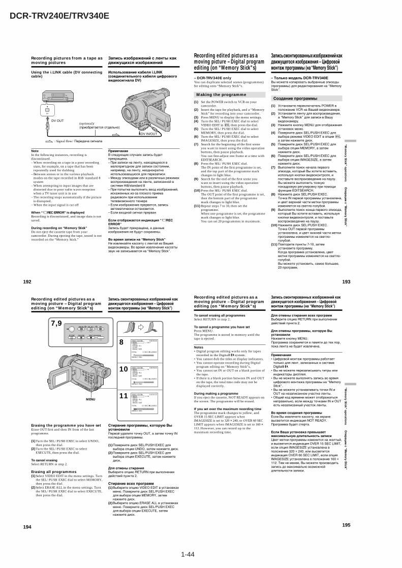
1-44
DCR-TRV240E/TRV340E
194
7,9
8
10
11
REW
REC
FF
PAUSESTOP
PLAY
320
VIDEO EDIT MARK UNDO ERASE ALL START IMAGE SIZE
TOTAL
[MENU] : END
0 SEC [ 15SEC]
0:08:55:061 OUT
320
VIDEO EDIT MARK UNDO ERASE ALL START IMAGE SIZE
TOTAL
[MENU] : END
3 SEC [ 15SEC]
0:08:55:062 IN
320
VIDEO EDIT MARK UNDO ERASE ALL START IMAGE SIZE
TOTAL
[MENU] : END
13 SEC [ 15SEC]
0:10:01:234 IN
MENU
Recording edited pictures as amoving picture – Digital programediting (on “Memory Stick”s)
Erasing the programme you have setErase OUT first and then IN from of the lastprogramme.
(1) Turn the SEL/PUSH EXEC to select UNDO,then press the dial.
(2) Turn the SEL/PUSH EXEC to selectEXECUTE, then press the dial.
To cancel erasingSelect RETURN in step 2.
Erasing all programmes(1) Select VIDEO EDIT in the menu settings. Turn
the SEL/PUSH EXEC dial to select MEMORY,then press the dial.
(2) Select ERASE ALL in the menu settings. Turnthe SEL/PUSH EXEC dial to select EXECUTE,then press the dial.
Запись смонтированных изображений какдвижущегося изображения – Цифровоймонтаж программы (на “Memory Stick”)
Стирание программы, которую ВыустановилиПервой удалите точку OUT, а затем точку INпоследней программы.
(1) Поверните диск SEL/PUSH EXEC длявыбора опции UNDO, затем нажмите диск.
(2) Поверните диск SEL/PUSH EXEC длявыбора опции EXECUTE, затем нажмитедиск.
Для отмены стиранияВыберите опцию RETURN при выполнениидействий пункта 2.
Стирание всех программ(1) Выберите опцию VIDEO EDIT в установках
меню. Поверните диск SEL/PUSH EXECдля выбора опции MEMORY, затемнажмите диск.
(2) Выберите опцию ERASE ALL в установкахменю. Поверните диск SEL/PUSH EXECдля выбора опции EXECUTE, затемнажмите диск.
195
“Mem
ory Stick ” o
peratio
ns О
пер
аци
и с
“Mem
ory S
tick”
To cancel erasing all programmesSelect RETURN in step 2.
To cancel a programme you have setPress MENU.The programme is stored in memory until thetape is ejected.
Notes•Digital program editing works only for tapes
recorded in the Digital8 system.•You cannot dub the titles or display indicators.•You cannot operate recording during Digital
program editing on “Memory Stick”s.•You cannot set IN or OUT on a blank portion of
the tape.•If there is a blank portion between IN and OUT
on the tape, the total time code may not bedisplayed correctly.
During making a programmeIf you eject the cassette, NOT READY appears onthe screen. The programme will be erased.
If you set over the maximum recording timeThe programme mark changes to yellow, andOVER 15 SEC LIMIT appears whenIMAGESIZE is set to 320 × 240, or OVER 60 SECLIMIT appears when IMAGESIZE is set to 160 ×112. However, you can record up to themaximum recording time.
Recording edited pictures as amoving picture – Digital programediting (on “Memory Stick”s)
Для отмены стирания всех программВыберите опцию RETURN при выполнениидействий пункта 2.
Для отмены программы, которую ВыустановилиНажмите кнопку MENU.Программа сохраняется в памяти до тех пор,пока лента не будет извлечена.
Примечания•Цифровой монтаж программы работает
только для лент, записанных в системеDigital8 .
•Вы не можете перезаписывать титры илииндикаторы дисплея.
•Вы не можете выполнять запись во времяцифрового монтажа программы на “MemoryStick”.
•Вы не можете устанавливать точки IN иOUT на незаписанном участке ленты.
•Общий код времени может отображатьсянеправильно, если между точками IN и OUTесть незаписанный участок ленты.
Во время создания программыЕсли Вы извлечете кассету, на экраневысветится индикация NOT READY.Программа будет стерта.
Если Ваша установка превышаетмаксимальную длительность записиЦвет метки программы изменится на желтый,и высветится индикация OVER 15 SEC LIMIT,если опция IMAGESIZE установлена вположение 320 × 240, или высветитсяиндикация OVER 60 SEC LIMIT, если опцияIMAGESIZE установлена в положение 160 ×112. Тем не менее, Вы можете производитьзапись до максимально возможнойдлительности записи.
Запись смонтированных изображений какдвижущегося изображения – Цифровоймонтаж программы (на “Memory Stick”)
192
Using the i.LINK cable (DV connectingcable)
NoteIn the following instances, recording isdiscontinued.– When recording on a tape in a poor recording
state, for example, on a tape that has beenrepeatedly used for dubbing
– Between scenes or in the various playbackmodes on the tape recorded in Hi8/standard 8system
– When attempting to input images that aredistorted due to poor radio wave receptionwhen a TV tuner unit is in use
– The recording stops automatically if the pictureis disrupted.
– When the input signal is cut off
When “ REC ERROR” is displayedRecording is discontinued, and image data is notsaved.
During recording on “Memory Stick”Do not eject the cassette tape from yourcamcorder. During ejecting the tape, sound is notrecorded on the “Memory Stick.”
Recording pictures from a tape asmoving pictures
Запись изображений с ленты какдвижущихся изображений
Использование кабеля i.LINK(соединительного кабеля цифровоговидеосигнала DV)
ПримечаниеВ следующих случаях запись будетпрекращена.– При записи на ленту, находящуюся в
малопригодном для записи состоянии,например, на ленту, неоднократноиспользовавшуюся для перезаписи
– Между эпизодами или в различных режимахвоспроизведения на ленте, записанной всистеме Hi8/standard 8
– При попытке выполнить ввод изображений,искаженных из-за плохого приемарадиоволн при использованиителевизионного тюнера
– Если изображение прервется, записьавтоматически остановится.
– Если входной сигнал прерван
Если отображается индикация “ RECERROR”Запись будет прекращена, а данныеизображения не будут сохранены.
Во время записи на “Memory Stick”Не извлекайте кассету с лентой из Вашейвидеокамеры. Во время извлечения кассетызвук не записывается на “Memory Stick”.
DV OUT
DV IN/OUT
DV
: Signal flow/Передача сигнала
(optional)/(приобретается отдельно)
193
“Mem
ory Stick ” o
peratio
ns О
пер
аци
и с “M
emo
ry Stick”
Recording edited pictures as amoving picture – Digital programediting (on “Memory Stick”s)
– DCR-TRV340E onlyYou can duplicate selected scenes (programmes)for editing onto “Memory Stick”s.
Making the programme
(1) Set the POWER switch to VCR on yourcamcorder.
(2) Insert the tape for playback, and a “MemoryStick” for recording into your camcorder.
(3) Press MENU to display the menu settings.(4) Turn the SEL/PUSH EXEC dial to select
VIDEO EDIT in , then press the dial.(5) Turn the SEL/PUSH EXEC dial to select
MEMORY, then press the dial.(6) Turn the SEL/PUSH EXEC dial to select
IMAGESIZE, then press the dial.(7) Search for the beginning of the first scene
you want to insert using the video operationbuttons, then pause playback.You can fine-adjust one frame at a time withEDITSEARCH.
(8) Press the SEL/PUSH EXEC dial.The IN point of the first programme is set,and the top part of the programme markchanges to light blue.
(9) Search for the end of the first scene youwant to insert using the video operationbuttons, then pause playback.
(10) Press the SEL/PUSH EXEC dial.The OUT point of the first programme is set,then the bottom part of the programmemark changes to light blue.
(11) Repeat steps 7 to 10, then set theprogramme.When one programme is set, the programmemark changes to light blue.You can set 20 programmes in maximum.
Запись смонтированных изображений какдвижущегося изображения – Цифровоймонтаж программы (на “Memory Stick”)
– Только модель DCR-TRV340EВы можете копировать выбранные эпизоды(программы) для редактирования на “MemoryStick”.
Создание программы
(1) Установите переключатель POWER вположение VCR на Вашей видеокамере.
(2) Установите ленту для воспроизведения,а “Memory Stick” для записи в Вашувидеокамеру.
(3) Нажмите кнопку MENU для отображенияустановок меню.
(4) Поверните диск SEL/PUSH EXEC длявыбора режима VIDEO EDIT в опции ,а затем нажмите диск.
(5) Поверните диск SEL/PUSH EXEC длявыбора опции MEMORY, а затемнажмите диск.
(6) Поверните диск SEL/PUSH EXEC длявыбора опции IMAGESIZE, а затемнажмите диск.
(7) Выполните поиск начала первогоэпизода, который Вы хотите вставить,используя кнопки видеоконтроля, ипоставьте воспроизведение на паузу.Вы можете выполнить тонкуюпокадровую регулировку при помощифункции EDITSEARCH.
(8) Нажмите диск SEL/PUSH EXEC.Точка IN первой программы установлена,и цвет верхней части метки программыизменяется на светло-голубой.
(9) Выполните поиск конца первого эпизода,который Вы хотите вставить, используякнопки видеоконтроля, и поставьтевоспроизведение на паузу.
(10) Нажмите диск SEL/PUSH EXEC.Точка OUT первой программыустановлена, и цвет нижней части меткипрограммы изменяется на светло-голубой.
(11) Повторите пункты 7-10, затемустановите программу.Когда программа установлена, цветметки программы изменяется на светло-голубой.Вы можете установить, самое большее,20 программ.
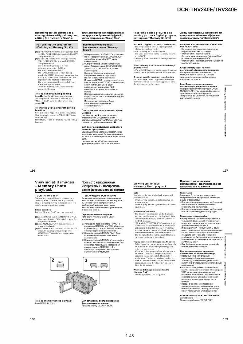
1-45
DCR-TRV240E/TRV340E
196
Performing the programme(Dubbing a “Memory Stick”)
(1) Select VIDEO EDIT in the menu settings. Turnthe SEL/PUSH EXEC dial to select MEMORY,then press the dial.
(2) Select START in the menu settings. Turn theSEL/PUSH EXEC dial to select EXECUTE,then press the dial.Search for the beginning of the firstprogramme, then start dubbing.The programme mark flashes.The SEARCH indicator appears duringsearch, the EDITING indicator appears duringwriting of data on your camcorder, and RECappears during dubbing on the screen.The programme mark changes to light blueafter dubbing is complete.When the dubbing ends, your camcorderautomatically stops.
To stop dubbing during editingPress x using the video operation buttons.The programme you made is recorded on a“Memory Stick” up to the place where youpressed x.
To end the Digital program editingfunctionYour camcorder stops when the dubbing ends.Then the display returns to VIDEO EDIT in themenu settings.Press MENU to end the Digital program editingfunction.
Recording edited pictures as amoving picture – Digital programediting (on “Memory Stick”s)
Запись смонтированных изображений какдвижущегося изображения – Цифровоймонтаж программы (на “Memory Stick”)
Выполнение программы(перезапись ленты “MemoryStick”)
(1) Выберите опцию VIDEO EDIT в установкахменю. Поверните диск SEL/PUSH EXECдля выбора опции MEMORY, затемнажмите диск.
(2) Выберите опцию START в установкахменю. Поверните диск SEL/PUSH EXECдля выбора опции EXECUTE, затемнажмите диск.Выполните поиск начала первойпрограммы и начните перезапись.Начнет мигать метка программы.Индикатор SEARCH появляется во времяпоиска, индикатор EDITING появляется вовремя записи данных на Вашувидеокамеру, а индикатор RECпоявляется во время перезаписи наэкране.Программная метка изменится на светло-голубую после того, как перезапись будетпрекращена.По окончании перезаписи Вашавидеокамера автоматическиостанавливается.
Для остановки перезаписи во времямонтажаНажмите кнопку x используя кнопкивидеоконтроля. Создаваемая Вамипрограмма запишется на “Memory Stick” дотого места, где Вы нажали кнопку x.
Для окончания функции цифровогомонтажа программыВаша видеокамера останавливается, когдаперезапись завершена. Затем отображениеустановок меню возвращается к опции VIDEOEDIT.Нажмите кнопку MENU для окончанияфункции цифрового монтажа программы.
197
“Mem
ory Stick ” o
peratio
ns О
пер
аци
и с “M
emo
ry Stick”
NOT READY appears on the LCD screen when:– The programme to operate Digital program
editing has not been made.– The “Memory Stick” is not inserted.– The write-protect tab on the “Memory Stick” is
set to LOCK.– “Memory Stick” does not have enough space to
record.
When “Memory Stick” does not have enoughspace to recordLOW MEMORY appears on the screen. However,you can record pictures up to the time indicated.
If you set over the maximum recording timeOVER MEMORY LIMIT appears on the screen.However, you can record moving pictures up tothe maximum recording time.
Recording edited pictures as amoving picture – Digital programediting (on “Memory Stick”s)
Запись смонтированных изображений какдвижущегося изображения – Цифровоймонтаж программы (на “Memory Stick”)
На экране ЖКД высвечивается индикацияNOT READY, если:– Не создана программа для выполнения
цифрового монтажа программы.– “Memory Stick” не установлена.– Лепесток защиты записи на “Memory Stick”
установлен в положение LOCK.– “Memory Stick” не имеет достаточный объем
памяти для записи.
Когда “Memory Stick” не имеетдостаточный объем памяти для записиНа экране появляется индикация LOWMEMORY. Тем не менее, Вы можетепроизводить запись до отображаемойдлительности записи.
Если Ваша установка превышаетмаксимальную длительность записиНа экране высветится индикация OVERMEMORY LIMIT. Тем не менее, Вы можетепроизводить запись движущихсяизображений до максимально возможнойдлительности записи.
198
– DCR-TRV340E onlyYou can play back still images recorded on a“Memory Stick”. You can also play back siximages including moving pictures in order at atime by selecting the index screen.
Before operationInsert a “Memory Stick” into your camcorder.
(1) Set the POWER switch to MEMORY or VCR.Make sure that the LOCK switch is set to theleft (unlock) position.
(2) Press MEMORY PLAY. The last recordedimage is displayed.
(3) Press MEMORY +/– to select the desired stillimage. To see the previous image, pressMEMORY –. To see the next image, pressMEMORY +.
To stop memory photo playbackPress MEMORY PLAY.
Viewing still images– Memory Photoplayback
– Только модель DCR-TRV340EВы можете воспроизводить неподвижныеизображения, записанные на “Memory Stick”.Вы можете также воспроизводить 6изображений, включая движущиесяизображения, одновременно путем выбораиндексного экрана.
Перед выполнением операцииУстановите “Memory Stick” в Вашувидеокамеру.
(1) Установите переключатель POWER вположение MEMORY или VCR. Убедитесь,что фиксатор LOCK установлен в левом(незафиксированном) положении.
(2) Нажмите кнопку MEMORY PLAY. Будетотображено последнее записанноеизображение.
(3) Нажмите кнопку MEMORY +/– для выборанужного неподвижного изображения. Дляпросмотра предыдущего изображениянажмите кнопку MEMORY –. Дляпросмотра следующего изображениянажмите кнопку MEMORY +.
Для остановки воспроизведенияфотоснимков из памятиНажмите кнопку MEMORY PLAY.
Просмотр неподвижныхизображений – Воспроизве-дение фотоснимков из памяти
32PLAY
199
“Mem
ory Stick ” o
peratio
ns О
пе
ра
ци
и с
“Me
mo
ry S
tick
”
Viewing still images– Memory Photo playback
NoteYou may not be able to play back images withyour camcorder:– When playing back image data modified on
your computer.– When playing back image data shot with other
equipment.
Notes on the file name•The directory number may not be displayed
and only the file name may be displayed if thestructure of the directory does not conform tothe DCF standard.
•“ - DIRECTORY ERROR” may appear onthe screen if the structure of the directory doesnot conform to the DCF standard. While thismessage appears, you can play back images butcannot record them on the “Memory Stick.”
•The file name flashes on the screen if the file iscorrupted or the file is unreadable.
To play back recorded images on a TV screen•Before operation connect your camcorder to the
TV with the A/V connecting cable suppliedwith your camcorder.
•When operating memory photo playback on aTV or the LCD screen, image quality mayappear to have deteriorated. This is not amalfunction. The image data is as good as ever.
•Turn the audio volume of the TV down beforeoperation, or noise (howling) may be outputfrom the TV speakers.
When no still image is recorded on the“Memory Stick”The message “ NO FILE” appears.
Просмотр неподвижныхизображений – Воспроизведениефотоснимков из памяти
ПримечаниеВозможно, Вы не сможете выполнитьвоспроизведение изображений с помощьюВашей видеокамеры:– При воспроизведении данных изображений,
видоизмененных с помощью Вашегоперсонального компьютера.
– При воспроизведении данных изображений,снятых с помощью другой аппаратуры.
Примечания о имени файла•Номер каталог может не отображаться, и
только имя файла может отображаться,если структура каталога не соответствуеттребованиям стандарта DCF.
•Индикация “ - DIRECTORY ERROR”может появиться на экране, если структуракаталога не соответствует требованиямстандарта DCF. Пока это сообщениеотображается, Вы сможете воспроизводитьизображения, но не сможете их записыватьна “Memory Stick”.
•Имя файла мигает на экране, если файлповрежден или не читается.
Для воспроизведения записанныхизображений на экране телевизора•Перед выполнением операции
подсоедините Вашу видеокамеру ктелевизору с помощью соединительногокабеля аудио/видео, прилагаемого к Вашейвидеокамере.
•При воспроизведении фотоснимков изпамяти на экране телевизора или на экранеЖКД, качество изображения можетвыглядеть ухудшенным. Это не являетсянеисправностью. Данные изображениянаходятся в том же состоянии, что ипрежде.
•Перед началом воспроизведенияуменьшите громкость телевизора, иначечерез акустическую систему телевизораможет послышаться шум (завывание).
Если на “Memory Stick” нет записанныхизображенийПоявится сообщение “ NO FILE”.
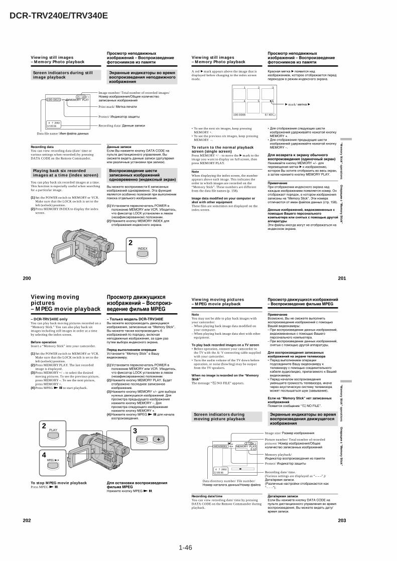
1-46
DCR-TRV240E/TRV340E
202
– DCR-TRV340E onlyYou can play back moving pictures recorded on a“Memory Stick.” You can also play back siximages including still images in order at a timeby selecting the index screen.
Before operationInsert a “Memory Stick” into your camcorder.
(1)Set the POWER switch to MEMORY or VCR.Make sure that the LOCK switch is set to theleft (unlock) position.
(2)Press MEMORY PLAY. The last recordedimage is displayed.
(3)Press MEMORY +/– to select the desiredmoving pictures. To see the previous picture,press MEMORY –. To see the next picture,press MEMORY +.
(4)Press MPEG N X to start playback.
To stop MPEG movie playbackPress MPEG N X.
32
4
PLAY
MPEG
Viewing movingpictures– MPEG movie playback
– Только модель DCR-TRV340EВы можете воспроизводить движущиесяизображения, записанные на “Memory Stick”.Вы можете также воспроизводить 6изображений по порядку, включаянеподвижные изображения, за один разпутем выбора индексного экрана.
Перед выполнением операцииУстановите “Memory Stick” в Вашувидеокамеру.
(1)Установите переключатель POWER вположение MEMORY или VCR. Убедитесь,что фиксатор LOCK установлен в левом(незафиксированном) положении.
(2)Нажмите кнопку MEMORY PLAY. Будетотображено последнее записанноеизображение.
(3)Нажмите кнопку MEMORY +/– для выборанужных движущихся изображений. Дляпросмотра предыдущего изображениянажмите кнопку MEMORY –. Дляпросмотра следующего изображениянажмите кнопку MEMORY +.
(4)Нажмите кнопку MPEG N X для началавоспроизведения.
Для остановки воспроизведенияфильма MPEGНажмите кнопку MPEG N X.
Просмотр движущихсяизображений – Воспроиз-ведение фильма MPEG
203
“Mem
ory Stick ” o
peratio
ns О
пер
аци
и с “M
emo
ry Stick”
NoteYou may not be able to play back images withyour camcorder:– When playing back image data modified on
your computer.– When playing back image data shot with other
equipment.
To play back recorded images on a TV screen•Before operation, connect your camcorder to
the TV with the A/V connecting cable suppliedwith your camcorder.
•Turn the audio volume of the TV down beforeoperation, or noise (howling) may be outputfrom the TV speakers.
When no image is recorded on the “MemoryStick”The message “ NO FILE” appears.
Screen indicators duringmoving picture playback
Recording date/timeYou can view recording date/time by pressingDATA CODE on the Remote Commander duringplayback.
Viewing moving pictures– MPEG movie playback
ПримечаниеВозможно, Вы не сможете выполнитьвоспроизведение изображений с помощьюВашей видеокамеры:– При воспроизведении данных изображений,
видоизмененных с помощью Вашегоперсонального компьютера.
– При воспроизведении данных изображений,снятых с помощью другой аппаратуры.
Для воспроизведения записанныхизображений на экране телевизора•Перед выполнением операции
подсоедините Вашу видеокамеру ктелевизору с помощью соединительногокабеля аудио/видео, прилагаемого к Вашейвидеокамере.
•Перед началом воспроизведенияуменьшите громкость телевизора, иначечерез акустическую систему телевизораможет послышаться шум (завывание).
Если на “Memory Stick” нет записанныхизображенийПоявится сообщение “ NO FILE”.
Экранные индикаторы во времявоспроизведения движущегосяизображения
Дата/время записиЕсли Вы нажмете кнопку DATA CODE напульте дистанционного управления во времявоспроизведения, Вы можете видеть дату/время записи.
Просмотр движущихся изображений– Воспроизведение фильма MPEG
Picture number/Total number of recordedpictures/Номер изображения/Общееколичество записанных изображений
Image size/Размер изображения
Data directory number/File number/Номер каталога данных/Номер файла
Protect/Индикатор защиты
4 7 200212:05:56
320
–– ––– –
MOV000012 / 20
MEMORY PLAY 0:12
Memory playback/Индикатор воспроизведения из памяти
Recording date/time.(Various settings are displayed as “– – –”.)/Дата/время записи.(Различные настройки отображаются как“– – –”).
200
Screen indicators during stillimage playback
Recording dataYou can view recording data (date/time orvarious settings when recorded) by pressingDATA CODE on the Remote Commander.
Playing back six recordedimages at a time (index screen)
You can play back six recorded images at a time.This function is especially useful when searchingfor a particular image.
(1) Set the POWER switch to MEMORY or VCR.Make sure that the LOCK switch is set to theleft (unlock) position.
(2) Press MEMORY INDEX to display the indexscreen.
Viewing still images– Memory Photo playback
Просмотр неподвижныхизображений – Воспроизведениефотоснимков из памяти
Экранные индикаторы во времявоспроизведения неподвижногоизображения
Данные записиЕсли Вы нажмете кнопку DATA CODE напульте дистанционного управления, Высможете видеть данные записи (дату/времяили различные установки при записи).
Воспроизведение шестизаписанных изображенийодновременно (индексный экран)
Вы можете воспроизвести 6 записанныхизображений одновременно. Эта функцияявляется особенно полезной при выполнениипоиска отдельного изображения.
(1) Установите переключатель POWER вположение MEMORY или VCR. Убедитесь,что фиксатор LOCK установлен в левом(незафиксированном) положении.
(2) Нажмите кнопку MEMORY INDEX дляотображения индексного экрана.
21 / 40MEMORY PLAY100-0021
4 7 200212:05:56
Data file name/Имя файла данных
Image number/Total number of recorded images/Номер изображения/Общее количествозаписанных изображений
Protect/Индикатор защиты
Print mark/Метка печати
Recording data/Данные записи
2INDEX
201
“Mem
ory Stick ” o
peratio
ns О
пер
аци
и с “M
emo
ry Stick”
A red B mark appears above the image that isdisplayed before changing to the index screenmode.
•To see the next six images, keep pressingMEMORY +.
•To see the previous six images, keep pressingMEMORY –.
To return to the normal playbackscreen (single screen)Press MEMORY +/– to move the B mark to theimage you want to display on full screen, thenpress MEMORY PLAY.
NoteWhen displaying the index screen, the numberappears above each image. This indicates theorder in which images are recorded on the“Memory Stick”. These numbers are differentfrom the data file names (p. 158).
Image data modified on your computer orshot with other equipmentThese files are sometimes not displayed on theindex screen.
Viewing still images– Memory Photo playback
Просмотр неподвижныхизображений – Воспроизведениефотоснимков из памяти
Красная метка B появится надизображением, которое отображается передпереходом в режим индексного экрана.
•Для отображения следующих шестиизображений удерживайте нажатой кнопкуMEMORY +.
•Для отображения предыдущих шестиизображений удерживайте нажатой кнопкуMEMORY –.
Для возврата к экрану обычноговоспроизведения (одиночный экран)Нажимайте кнопку MEMORY +/– дляперемещения метки B к изображению,которое Вы хотите отобразить во весь экран,а затем нажмите кнопку MEMORY PLAY.
ПримечаниеПри отображении индексного экрана надкаждым изображением появляется номер. Онотображает порядок, в котором изображениязаписаны на “Memory Stick”. Эти номераотличаются от имен файлов данных (стр. 158).
Данные изображений, видоизмененных спомощью Вашего персональногокомпьютера или снятых с помощью другойаппаратурыЭти файлы иногда могут не отображаться наиндексном экране.
B mark/метка B
6 / 40100-0006
1 2 3
4 5 6
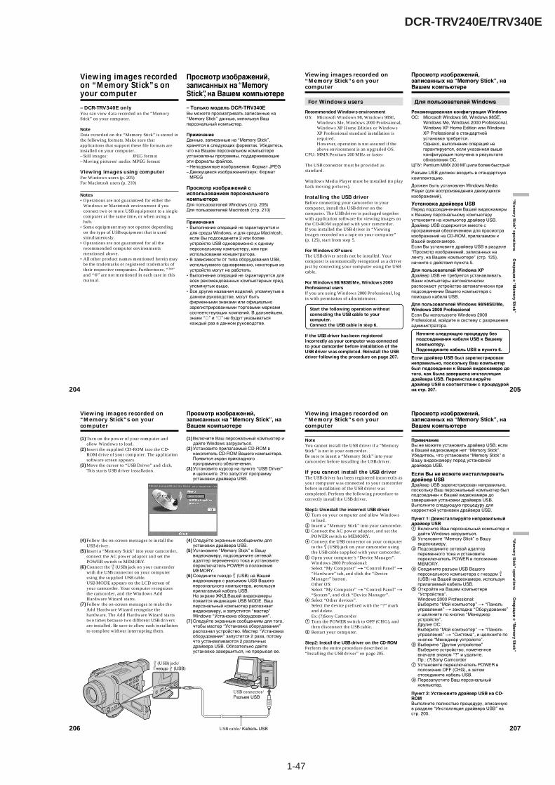
1-47
DCR-TRV240E/TRV340E
204
Viewing images recordedon “Memory Stick”s onyour computer
– DCR-TRV340E onlyYou can view data recorded on the “MemoryStick” on your computer.
NoteData recorded on the “Memory Stick” is stored inthe following formats. Make sure thatapplications that support these file formats areinstalled on your computer.– Still images: JPEG format– Moving pictures/audio: MPEG format
Viewing images using computerFor Windows users (p. 205)For Macintosh users (p. 210)
Notes•Operations are not guaranteed for either the
Windows or Macintosh environment if youconnect two or more USB equipment to a singlecomputer at the same time, or when using ahub.
•Some equipment may not operate dependingon the type of USB equipment that is usedsimultaneously.
•Operations are not guaranteed for all therecommended computer environmentsmentioned above.
•All other product names mentioned herein maybe the trademarks or registered trademarks oftheir respective companies. Furthermore, “™”and “®” are not mentioned in each case in thismanual.
Просмотр изображений,записанных на “MemoryStick”, на Вашем компьютере
– Только модель DCR-TRV340EВы можете просматривать записанные на“Memory Stick” данные, используя Вашперсональный компьютер.
ПримечаниеДанные, записанные на “Memory Stick”,хранятся в следующих форматах. Убедитесь,что на Вашем персональном компьютереустановлены программы, поддерживающиеэти форматы файлов.– Неподвижные изображения: Формат JPEG– Движущиеся изображения/звук: Формат
MPEG
Просмотр изображений сиспользованием персональногокомпьютераДля пользователей Windows (стр. 205)Для пользователей Macintosh (стр. 210)
Примечания•Выполнение операций не гарантируется и
для среды Windows, и для среды Macintosh,если Вы подсоедините 2 или болееустройств USB одновременно к одномуперсональному компьютеру, или прииспользовании концентратора.
•В зависимости от типа оборудования USB,используемого одновременно, некоторые изустройств могут не работать.
•Выполнение операций не гарантируется длявсех рекомендованных компьютерных сред,упомянутых выше.
•Все другие названия изделий, упомянутые вданном руководстве, могут бытьфирменными знаками или официальнозарегистрированными торговыми маркамисоответствующих компаний. В дальнейшем,знаки “ ” и “ ” не будут указыватьсякаждый раз в данном руководстве.
205
“Mem
ory Stick ” o
peratio
ns О
пер
аци
и с “M
emo
ry Stick”
Viewing images recorded on“Memory Stick”s on yourcomputer
For Windows users
Recommended Windows environmentOS: Microsoft Windows 98, Windows 98SE,
Windows Me, Windows 2000 Professional,Windows XP Home Edition or WindowsXP Professional standard installation isrequired.However, operation is not assured if theabove environment is an upgraded OS.
CPU: MMX Pentium 200 MHz or faster
The USB connector must be provided asstandard.
Windows Media Player must be installed (to playback moving pictures).
Installing the USB driverBefore connecting your camcorder to yourcomputer, install the USB driver on thecomputer. The USB driver is packaged togetherwith application software for viewing images onthe CD-ROM supplied with your camcorder.If you installed the USB driver in “Viewingimages recorded on a tape on your computer”(p. 125), start from step 5.
For Windows XP usersThe USB driver needs not be installed. Yourcomputer is automatically recognized as a driverjust by connecting your computer using the USBcable.
For Windows 98/98SE/Me, Windows 2000Professional usersIf you are using Windows 2000 Professional, login with permission of administrator.
Start the following operation withoutconnecting the USB cable to yourcomputer.Connect the USB cable in step 6.
If the USB driver has been registeredincorrectly as your computer was connectedto your camcorder before installation of theUSB driver was completed. Reinstall the USBdriver following the procedure on page 207.
Просмотр изображений,записанных на “Memory Stick”, наВашем компьютере
Для пользователей Windows
Рекомендованная конфигурация WindowsОС: Microsoft Windows 98, Windows 98SE,
Windows Me, Windows 2000 Professional,Windows XP Home Edition или WindowsXP Professional в стандартнойустановке требуется.Однако, выполнение операций негарантируется, если указанная вышеконфигурация получена в результатеобновления ОС.
ЦПУ: Pentium MMX 200 МГц или более быстрый
Разъем USB должен входить в стандартнуюкомплектацию.
Должен быть установлен Windows MediaPlayer (для воспроизведения движущихсяизображений).
Установка драйвера USBПеред подсоединением Вашей видеокамерык Вашему персональному компьютеруустановите на компьютер драйвер USB.Драйвер USB содержится вместе спрограммным обеспечением для просмотраизображений на CD-ROM, прилагаемом кВашей видеокамере.Если Вы установите драйвер USB в разделе“Просмотр изображений, записанных наленту, на Вашем компьютере” (стр. 125),начните с действия пункта 5.
Для пользователей Windows XPДрайвер USB не требуется устанавливать.Ваши компьютеры автоматическираспознают устройство автоматически приподсоединении Вашего компьютера спомощью кабеля USB.
Для пользователей Windows 98/98SE/Me,Windows 2000 ProfessionalЕсли Вы используете Windows 2000Professional, войдите в систему с разрешенияадминистратора.
Начните следующую процедуру безподсоединения кабеля USB к Вашемукомпьютеру.Подсоедините кабель USB в пункте 6.
Если драйвер USB был зарегистрированнеправильно, поскольку Ваш компьютербыл подсоединен к Вашей видеокамере дотого, как была завершена инсталляциядрайвера USB. Переинсталлируйтедрайвер USB в соответствии с процедуройна стр. 207.
206
Viewing images recorded on“Memory Stick”s on yourcomputer
Просмотр изображений,записанных на “Memory Stick”, наВашем компьютере
(1) Turn on the power of your computer andallow Windows to load.
(2) Insert the supplied CD-ROM into the CD-ROM drive of your computer. The applicationsoftware screen appears.
(3) Move the cursor to “USB Driver” and click.This starts USB driver installation.
(4) Follow the on-screen messages to install theUSB driver.
(5) Insert a “Memory Stick” into your camcorder,connect the AC power adaptor and set thePOWER switch to MEMORY.
(6) Connect the (USB) jack on your camcorderwith the USB connector on your computerusing the supplied USB cable.USB MODE appears on the LCD screen ofyour camcorder. Your computer recognizesthe camcorder, and the Windows AddHardware Wizard starts.
(7) Follow the on-screen messages to make theAdd Hardware Wizard recognize thehardware. The Add Hardware Wizard startstwo times because two different USB driversare installed. Be sure to allow each installationto complete without interrupting them.
(1) Включите Ваш персональный компьютер идайте Windows загрузиться.
(2) Установите прилагаемый CD-ROM внакопитель CD-ROM Вашего компьютера.Появится экран прикладногопрограммного обеспечения.
(3) Установите курсор на пункте “USB Driver”и щелкните. Это запустит программуустановки драйвера USB.
(4) Следуйте экранным сообщениям дляустановки драйвера USB.
(5) Установите “Memory Stick” в Вашувидеокамеру, подсоедините сетевойадаптер переменного тока и установитепереключатель POWER в положениеMEMORY.
(6) Соедините гнездо (USB) на Вашейвидеокамере с разъемом USB Вашегоперсонального компьютера, используяприлагаемый кабель USB.На экране ЖКД Вашей видеокамерыпоявится индикация USB MODE. Вашперсональный компьютер распознаетвидеокамеру, и запустится “мастер”Windows “Установка оборудования”.
(7) Следуйте экранным сообщениям для того,чтобы мастер “Установка оборудования”распознал устройство. Мастер “Установкаоборудования” запустится 2 раза, потомучто устанавливаются 2 различныхдрайвера USB. Обязательно дайтеустановке завершиться, не прерывая ее.
USB connector/Разъем USB
(USB) jack/Гнездо (USB)
USB cable/Кабель USB 207
“Mem
ory Stick ” o
peratio
ns О
пе
ра
ци
и с
“Me
mo
ry S
tick
”
Viewing images recorded on“Memory Stick”s on yourcomputer
NoteYou cannot install the USB driver if a “MemoryStick” is not in your camcorder.Be sure to insert a “Memory Stick” into yourcamcorder before installing the USB driver.
If you cannot install the USB driverThe USB driver has been registered incorrectly asyour computer was connected to your camcorderbefore installation of the USB driver wascompleted. Perform the following procedure tocorrectly install the USB driver.
Step1: Uninstall the incorrect USB driver1 Turn on your computer and allow Windows
to load.2 Insert a “Memory Stick” into your camcorder.3 Connect the AC power adaptor, and set the
POWER switch to MEMORY.4 Connect the USB connector on your computer
to the (USB) jack on your camcorder usingthe USB cable supplied with your camcorder.
5 Open your computer’s “Device Manager”.Windows 2000 Professional:Select “My Computer” t “Control Panel” t“Hardware” tab, and click the “DeviceManager” button.Other OS:Select “My Computer” t “Control Panel” t“System”, and click “Device Manager”.
6 Select “Other devices”.Select the device prefixed with the “?” markand delete.Ex: (?)Sony Camcorder
7 Turn the POWER switch to OFF (CHG), andthen disconnect the USB cable.
8 Restart your computer.
Step2: Install the USB driver on the CD-ROMPerform the entire procedure described in“Installing the USB driver” on page 205.
Просмотр изображений,записанных на “Memory Stick”, наВашем компьютере
ПримечаниеВы не можете установить драйвер USB, еслив Вашей видеокамере нет “Memory Stick”.Убедитесь, что установили “Memory Stick” вВашу видеокамеру перед установкойдрайвера USB.
Если Вы не можете инсталлироватьдрайвер USBДрайвер USB зарегистрирован неправильно,поскольку Ваш персональный компьютер былподсоединен к Вашей видеокамере дозавершения установки драйвера USB.Выполните следующую процедуру длякорректной установки драйвера USB.
Пункт 1: Деинсталлируйте неправильныйдрайвер USB1 Включите Ваш персональный компьютер и
дайте Windows загрузиться.2 Установите “Memory Stick” в Вашу
видеокамеру.3 Подсоедините сетевой адаптер
переменного тока и установитепереключатель POWER в положениеMEMORY.
4 Соедините разъем USB Вашегоперсонального компьютера с гнездом (USB) на Вашей видеокамере, используяприлагаемый кабель USB.
5 Откройте на Вашем компьютере“Устройства”.Windows 2000 Professional:Выберите “Мой компьютер” t “Панельуправления” t закладка “Оборудование”и щелкните по кнопке “Менеджерустройств”.Другие ОС:Выберите “Мой компьютер” t “Панельуправления” t “Система”, и щелкните покнопке “Менеджер устройств”.
6 Выберите “Другие устройства”Выберите устройство, помеченноевначале знаком “?” и удалите.Пр.: (?)Sony Camcorder
7 Установите переключатель POWER вположение OFF (CHG), а затемотсоедините кабель USB.
8 Перезапустите Ваш персональныйкомпьютер.
Пункт 2: Установите драйвер USB на CD-ROMВыполните полностью процедуру, описаннуюв разделе “Инсталляция драйвера USB” настр. 205.

1-48
DCR-TRV240E/TRV340E
210
For Macintosh users
Recommended Macintosh environmentMac OS 8.5.1/8.6/9.0/9.1/9.2 or Mac OS X(v10.0/v10.1) standard installation is required.However, note that the update to Mac OS 9.0/9.1should be used for the following models.• iMac with the Mac OS 8.6 standard installation
and a slot loading type CD-ROM drive• iBook or Power Mac G4 with the Mac OS 8.6
standard installation
The USB connector must be provided asstandard.
Installing the USB driverBefore connecting your camcorder to yourcomputer, install the USB driver on thecomputer. The USB driver is packaged togetherwith application software for viewing images onthe CD-ROM supplied with your camcorder. Donot connect the USB cable to your computerbefore installation of the USB driver iscompleted.
For Mac OS 9.1/9.2/Mac OS X (v10.0/v10.1)The USB driver need not be installed. Your Macis automatically recognized as a driver just byconnecting your Mac using the USB cable.
Viewing images recorded on“Memory Stick”s on yourcomputer
Просмотр изображений,записанных на “Memory Stick”, наВашем компьютере
Для пользователей Macintosh
Рекомендованная конфигурация MacintoshMac OS 8.5.1/8.6/9.0/9.1/9.2 или Mac OS X(v10.0/v10.1) в стандартной установкетребуется.Однако, обратите внимание на то, чтоследует использовать обновление до Mac OS9.0/9.1 для следующих моделей.• iMac со стандартно установленной Mac OS
8.6 и накопителем CD-ROM c щелевойзагрузкой
• iBook или Power Mac G4 со стандартноустановленной Mac OS 8.6
Разъем USB должен входить в стандартнуюкомплектацию.
Установка драйвера USBПеред подсоединением Вашей видеокамерык Вашему компьютеру установите драйверUSB на компьютер. Драйвер USB упакованвместе с прикладным программнымобеспечением для просмотра изображений наCD-ROM, прилагаемом к Вашей видеокамере.Не подсоединяйте кабель USB к Вашемукомпьютеру до того, как завершитсяинсталляция.
Для Mac OS 9.1/9.2/Mac OS X (v10.0/v10.1)Драйвер USB не нуждается в установке. ВашMac автоматически распознает драйверсразу при подсоединении Вашего Mac сиспользованием кабеля USB.
211
“Mem
ory Stick ” o
peratio
ns О
пер
аци
и с “M
emo
ry Stick”
For Mac OS 8.5.1/8.6/9.0 users(1) Turn on your computer and allow the Mac OS
to load.(2) Insert the supplied CD-ROM into the CD-
ROM drive of your computer. The applicationsoftware screen appears.
(3) Click “USB Driver” to open the foldercontaining the six files related to “Driver”.
(4) Select all six files, and drag and drop theminto the System Folder.
(5) When the message appears, click “OK.”(6) Restart your computer.
Viewing images recorded on“Memory Stick”s on yourcomputer
Просмотр изображений,записанных на “Memory Stick”, наВашем компьютере
Для пользователей Mac OS 8.5.1/8.6/9.0(1) Включите Ваш персональный компьютер и
дайте Mac OS загрузиться.(2) Установите прилагаемый CD-ROM в
накопитель CD-ROM Вашего компьютера.Появится экран прикладногопрограммного обеспечения.
(3) Щелкните по кнопке “USB Driver” для того,чтобы открыть папку, содержащую 6файла, относящихся к программе “Driver”.
(4) Выберите все 6 файла и потяните иопустите их в системную папку.
(5) Если появится сообщение, щелкните покнопке “ОК”.
(6) Перезапустите Ваш персональныйкомпьютер.
208
Viewing images on WindowsAn application such as Windows Media Playermust be installed to play back moving pictures inWindows environment.
(1) Turn on your computer and allow Windowsto load.
(2) Insert a “Memory Stick” into your camcorder,and connect the AC power adaptor to yourcamcorder and then to a wall socket.
(3) Set the POWER switch to MEMORY.(4) Connect one end of the USB cable to the
(USB) jack on the camcorder and the otherend to the USB connector on your computer.USB MODE appears on the screen of yourcamcorder.
(5) Open “My Computer” on Windows anddouble click the newly recognized drive(Example: “Removable Disk (E:)”).The folders inside the “Memory Stick” aredisplayed.
(6) Select and double-click the desired image filefrom the folder.For the detailed folder and file name, see“Image file storage destinations and imagefiles” (p. 215).
USB connector/Разъем USB
USB cable/Кабель USB
(USB) jack/Гнездо (USB)
Viewing images recorded on“Memory Stick”s on yourcomputer
Просмотр изображений,записанных на “Memory Stick”, наВашем компьютере
Просмотр изображений в WindowsДля воспроизведения движущихсяизображений в среде Windows должно бытьустановлено приложение, такое, как,например, Windows Media Player.
(1) Включите Ваш персональный компьютер идайте Windows загрузиться.
(2) Установите “Memory Stick” в Вашувидеокамеру и подсоедините сетевойадаптер переменного тока к Вашейвидеокамере, а затем к сетевой розетке.
(3) Установите переключатель POWER вположение MEMORY.
(4) Подсоедините один конец кабеля USB кгнезду (USB) на видеокамере, а другойконец – к разъему USB Вашегоперсонального компьютера.На экране Вашей видеокамеры появитсяиндикация USB MODE.
(5) Откройте пиктограмму “Мой компьютер” вWindows и дважды щелкните по вновьраспознанному накопителю (Пример:“Removable Disk (E:) (Съемный диск (E:))”).Отобразятся папки внутри “Memory Stick”.
(6) Выберите и дважды щелкните по файлунужного изображения из папки.Для подробного описания названий папоки файлов обращайтесь к разделу “Местахранения файлов изображений и файлыизображений” (стр. 215).
209
“Mem
ory Stick ” o
peratio
ns О
пер
аци
и с “M
emo
ry Stick”
* Copying a file to the hard disk of yourcomputer before viewing it is recommended. Ifyou play back the file directly from the“Memory Stick,” the image and sound maybreak off.
Unplug the USB cable or eject the“Memory Stick”– For Windows 2000 Professional/Me,Windows XP usersTo unplug the USB cable or eject the “MemoryStick,” follow the procedure below.
(1) Move the cursor to the “Unplug or EjectHardware” icon on the Task Tray and click tocancel the applicable drive.
(2) A message to remove the device from thesystem appears, then unplug the USB cable oreject the “Memory Stick.”
(3) Set the POWER switch of your camcorder toOFF(CHG).
Desired file type/ Double-click in this order/Нужный тип файла Двойной щелчок в таком порядке
Still image/ “Dcim” folder t “100msdcf” folder t Image file/Неподвижное изображение Папка “Dcim” t Папка “100msdcf” t Файл изображения
Moving picture*/ “Mssony” folder t “Moml0001” folder t Image file*/Движущееся изображение* Папка “Mssony” t Папка “Moml0001” t Файл изображения*
Viewing images recorded on“Memory Stick”s on yourcomputer
Просмотр изображений,записанных на “Memory Stick”, наВашем компьютере
* Рекомендуется перед просмотромскопировать файл на жесткий диск Вашегоперсонального компьютера. Если Вы будетевоспроизводить файл прямо с “MemoryStick”, изображение и звук могут внезапнообрываться.
Отсоединение кабеля USB илиизвлечение “Memory Stick”– Для пользователей Windows 2000Professional/Me, Windows XPДля отсоединения кабеля USB иливыталкивания “Memory Stick”, выполнитеприведенную ниже процедуру.
(1) Переместите курсор на пиктограмму“Отключить или извлечь оборудование” впанели задач и щелкните для отменысоответствующего устройства.
(2) Появится сообщение об удаленииустройства из системы, а затемотсоедините кабель USB или извлеките“Memory Stick”.
(3) Установите переключатель POWER наВашей видеокамере в положение OFF(CHG).

1-49
DCR-TRV240E/TRV340E
212
Viewing images on MacintoshQuickTime 3.0 or newer must be installed to playback moving pictures in Macintosh environment.
(1) Turn on your computer and allow Mac OS toload.
(2) Insert a “Memory Stick” into your camcorder,and connect the AC power adaptor to yourcamcorder and then to a wall socket.
(3) Set the POWER switch to MEMORY.(4) Connect one end of the USB cable to the
(USB) jack on the camcorder and the otherend to the USB connector on your computer.USB MODE appears on the screen of yourcamcorder.
(5) Double click the newly recognized icon on thedesktop.The folders inside the “Memory Stick” aredisplayed.
(6) Select and double-click the desired image filefrom the folder.
* Copying a file to the hard disk of yourcomputer before viewing it is recommended. Ifyou play back the file directly from the“Memory Stick,” the image and sound maybreak off.
Viewing images recorded on“Memory Stick”s on yourcomputer
Просмотр изображений,записанных на “Memory Stick”, наВашем компьютере
Просмотр изображений в MacintoshДолжен быть установлен QuickTime 3.0 илиновее для воспроизведения движущихсяизображений в среде Macintosh.
(1) Включите Ваш персональный компьютер идайте Mac OS загрузиться.
(2) Установите “Memory Stick” в Вашувидеокамеру и подсоедините сетевойадаптер переменного тока к Вашейвидеокамере, а затем к сетевой розетке.
(3) Установите переключатель POWER вположение MEMORY.
(4) Подсоедините один конец кабеля USB кгнезду (USB) на видеокамере, а другойконец – к разъему USB Вашегоперсонального компьютера.На экране Вашей видеокамеры появитсяиндикация USB MODE.
(5) Дважды щелкните по вновь распознаннойпиктограмме на рабочем столе.Отобразятся папки внутри “Memory Stick”.
(6) Выберите и дважды щелкните по файлунужного изображения из папки.
* Рекомендуется перед просмотромскопировать файл на жесткий диск Вашегоперсонального компьютера. Если Вы будетевоспроизводить файл прямо с “MemoryStick”, изображение и звук могут внезапнообрываться.
Desired file type/ Double-click in this order/Нужный тип файла Двойной щелчок в таком порядке
Still image/ “Dcim” folder t “100msdcf” folder t Image file/Неподвижное изображение Папка “Dcim” t Папка “100msdcf” t Файл изображения
Moving picture*/ “Mssony” folder t “Moml0001” folder t Image file*/Движущееся изображение* Папка “Mssony” t Папка “Moml0001” t Файл изображения*
213
“Mem
ory Stick ” o
peratio
ns О
пер
аци
и с “M
emo
ry Stick”
Unplug the USB cable or eject the“Memory Stick”To unplug the USB cable or eject the “MemoryStick”, follow the procedure below.
(1) Close all running applications.Make sure that the access lamp of the harddisk is not lit.
(2) Drag and drop the “Memory Stick” icon to theTrash or select Eject under the Special menu.
(3) Unplug the USB cable or eject the “MemoryStick.”Set the POWER switch of your camcorder toOFF(CHG).
For Mac OS X (v10.0) usersShutting down your computer, then unplug theUSB cable or eject the “Memory Stick”.
Viewing images recorded on“Memory Stick”s on yourcomputer
Просмотр изображений,записанных на “Memory Stick”, наВашем компьютере
Отсоединение кабеля USB илиизвлечение “Memory Stick”Для отсоединения кабеля USB илиизвлечения “Memory Stick” следуйтенижеописанной процедуре.
(1) Закройте все открытые программы.Убедитесь, что лампа доступа жесткогодиска не горит.
(2) Потяните пиктограмму “Memory Stick” иотпустите ее над Корзиной или выделитеэту пиктограмму одинарным щелчком ивыберите команду Eject в меню Special.
(3) Отсоедините кабель USB или извлеките“Memory Stick”.Установите переключатель POWER наВашей видеокамере в положение OFF(CHG).
Для пользователей Mac OS X (v10.0)Отключите Ваш компьютер, а затемотсоедините кабель USB или извлеките“Memory Stick”.
214
Notes on using your computer
“Memory Stick”•“Memory Stick” operations on your camcorder
cannot be assured if a “Memory Stick”formatted on your computer is used on yourcamcorder, or if the “Memory Stick” in yourcamcorder was formatted from your computerwhen the USB cable was connected.
•Do not compress the data on the “MemoryStick.” Compressed files cannot be played backon your camcorder.
Software•Depending on your application software, the
file size may increase when you open a stillimage file.
•When you load an image modified usingretouching software from your computer toyour camcorder or when you directly modifythe image on your camcorder, the image formatwill differ so a file error indicator may appearand you may be unable to open the file.
Communications with your computerCommunications between your camcorder andyour computer may not recover after recoveringfrom Suspend, Resume, or Sleep.
Viewing images recorded on“Memory Stick”s on yourcomputer
Просмотр изображений,записанных на “Memory Stick”, наВашем компьютере
Примечания об использованииВашего персональногокомпьютера
“Memory Stick”•Работа “Memory Stick” на Вашей
видеокамере не гарантируется, если“Memory Stick”, отформатированная наВашем персональном компьютере,используется Вашей видеокамерой, илиесли “Memory Stick” была отформатированав Вашей видеокамере с Вашегоперсональном компьютера, когда былподсоединен кабель USB.
•Не сжимайте данные на “Memory Stick”.Сжатые файлы не воспроизводятся наВашей видеокамере.
Программное обеспечение•В зависимости от прикладной программы,
размер файла может увеличиться, когда Выоткрываете неподвижное изображение.
•Когда Вы загружаете изображение,видоизмененное с помощью программы дляретуширования, с Вашего персональногокомпьютера в Вашу видеокамеру или когдаВы напрямую видоизменяете изображениев видеокамере, формат изображенияизменится, так что может появитьсяиндикатор ошибки файла и, возможно, Выне сможете открыть файл.
Связь с Вашим персональнымкомпьютеромСвязь между Вашей видеокамерой и Вашимперсональным компьютером может невосстановиться после выхода компьютера изрежимов Пауза, Возобновление или Спящийрежим.
215
“Mem
ory Stick ” o
peratio
ns О
пе
ра
ци
и с
“Me
mo
ry S
tick
”
Folder containing moving picture data/Папка, содержащая данныедвижущихся изображений
Folder containing still image data/Папка, содержащая данныенеподвижных изображений
Image file storage destinationsand image files
Image files recorded with your camcorder aregrouped in folders by recording mode.The meanings of the file names are as follows.ssss stands for any number within the rangefrom 0001 to 9999.
For Windows Me users(The drive recognizing yourcamcorder is [E:].)
Viewing images recorded on“Memory Stick”s on yourcomputer
Просмотр изображений,записанных на “Memory Stick”, наВашем компьютере
Места хранения файловизображений и файлыизображений
Файлы изображений, записанные с помощьюВашей видеокамеры, сгруппированы в папкипо режиму записи.Значения имен файлов таковы.ssss обозначает любое число в диапазонеот 0001 до 9999.
Для пользователей Windows Me(Устройство, представляющеевидеокамеру – [E:].)
Folder/Папка File/Файл Meaning/Значение
100MSDCF DSC0ssss.JPGStill image file/Файл неподвижного изображения
MOML0001 MOV0ssss.MPGMoving picture file/Файл движущегося изображения
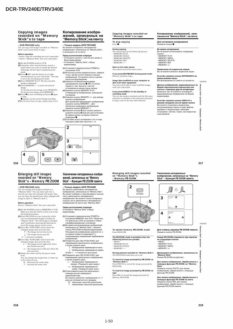
1-50
DCR-TRV240E/TRV340E
218
Enlarging still imagesrecorded on “MemoryStick”s – Memory PB ZOOM
– DCR-TRV340E onlyYou can enlarge still images recorded on a“Memory Stick.” You can select and view adesired part from the enlarged still image. Also,you can copy the desired part of the enlarged stillimage to tapes or “Memory Stick”s.
Before operationInsert a “Memory Stick” into your camcorder.
(1) Set the POWER switch to MEMORY or VCR.Make sure that the LOCK switch is set to theleft (unlock) position.
(2) Press PB ZOOM on your camcorder whileyou are playing back images recorded on“Memory Stick.” The still image is enlarged,and R r indicators showing the direction tomove the image appear on the screen.
(3) Turn SEL/PUSH EXEC dial to move theenlarged image, then press the dial.
R : The image moves downward.r : The image moves upward.
T t becomes available.(4) Turn SEL/PUSH EXEC dial to move the
enlarged image, then press the dial.T : The image moves rightward. (Turn
the dial downward.)t : The image moves leftward. (Turn the
dial upward.)(5) Adjust the zoom ratio by the power zoom
lever.You can enlarge the image from 1.1 times upto five times its size.
W : Decreases the zoom ratio.T : Increase the zoom ratio.
Увеличение неподвижных изобра-жений, записанных на “MemoryStick” – Функция PB ZOOM памяти
– Только модель DCR-TRV340EВы можете увеличивать неподвижныеизображения, записанные на “Memory Stick”.Вы может выбирать и просматривать нужнуючасть увеличенного неподвижногоизображения. Вы можете также копироватьнужную часть увеличенного неподвижногоизображения на ленты или “Memory Stick”.
Перед выполнением операцииУстановите “Memory Stick” в Вашувидеокамеру.
(1) Установите переключатель POWER вположение MEMORY или VCR. Убедитесь,что фиксатор LOCK установлен в левом(незафиксированном) положении.
(2) Во время воспроизведения изображений,записанных на “Memory Stick”, нажмитекнопку PB ZOOM на Вашей видеокамере.Неподвижное изображение увеличится, ана экране появится индикация R r,показывающая направление перемещенияизображения.
(3) Поверните диск SEL/PUSH EXEC дляперемещения увеличенного изображения,а затем нажмите диск.
R : Изображение перемещается вниз.r : Изображение перемещается вверх.
Опция T t становится доступной.(4) Поверните диск SEL/PUSH EXEC для
перемещения увеличенного изображения,а затем нажмите диск.
T : Изображения перемещаетсявправо. (Поверните диск вверх.)
t : Изображение перемещаетсявлево. (Поверните диск вниз.)
(5) Отрегулируйте масштаб увеличения спомощью рычага приводноговариообъектива.Вы можете увеличить изображение от 1,1раза до пятикратного его размера.
W : Уменьшает масштаб увеличения.T : Увеличивает масштаб увеличения.
219
“Mem
ory Stick ” o
peratio
ns О
пер
аци
и с “M
emo
ry Stick”
5
2PB ZOOM
3
4
PB ZOOM × 5.0
[EXEC] : T t
PB ZOOM × 5.0
[EXEC] : r R
To cancel memory PB ZOOM modePress PB ZOOM.
The PB ZOOM mode is cancelled when thefollowing buttons are pressed:– MENU– MEMORY PLAY– MEMORY INDEX– MEMORY +/–
Moving pictures recorded on “Memory Stick”sThe PB ZOOM mode does not work.
To record an image processed by PB ZOOM on“Memory Stick”sPress PHOTO to record the image processed byPB ZOOM.
To record an image processed by PB ZOOM ontapePress REC to record the image processed byMemory PB ZOOM.
Enlarging still images recordedon “Memory Stick”s– Memory PB ZOOM
Для отмены режима PB ZOOM памятиНажмите кнопку PB ZOOM.
Режим PB ZOOM отменяется при нажатиина следующие кнопки:– MENU– MEMORY PLAY– MEMORY INDEX– MEMORY +/–
Движущиеся изображения, записанные на“Memory Stick”Режим PB ZOOM не работает.
Для записи изображения, обработанного спомощью функции PB ZOOM, на “MemoryStick”Нажмите кнопку PHOTO для записиизображения, обработанного с помощьюфункции PB ZOOM.
Для записи изображения, обработанного спомощью функции PB ZOOM на лентеНажмите кнопку REC для записиизображения, обработанного с помощьюфункции PB ZOOM памяти.
Увеличение неподвижныхизображений, записанных на “MemoryStick” – Функция PB ZOOM памяти
216
Copying imagesrecorded on “MemoryStick”s to tape
– DCR-TRV340E onlyYou can copy still images recorded on “MemoryStick”s and record them to tapes.
Before operation•Insert a tape for recording into your camcorder.•Insert a “Memory Stick” into your camcorder.
(1) Set the POWER switch to VCR.(2) Using the video control buttons, search a
point where you want to record the desiredstill image. Set the tape to playback pausemode.
(3) Press z REC and the button on its rightsimultaneously on your camcorder. The tapeis set to the recording pause mode.
(4) Press MEMORY PLAY. The last recordedimage is displayed.
(5) Press MEMORY+/– to select the desiredimage.To see the previous image, press MEMORY–.To see the next image, press MEMORY+.
(6) Press X to start recording and press X againto stop.z appears on the screen during recording.
(7) If you have more to copy, repeat steps 4 to 6.
64
3
2
REC
PAUSE
5PLAY
Копирование изобра-жений, записанных на“Memory Stick”, на ленту
– Только модель DCR-TRV340EВы можете копировать неподвижныеизображения, записанные на “Memory Stick”,и записывать их на ленту.
Перед выполнением операции•Установите кассету с лентой для записи в
Вашу видеокамеру.•Установите “Memory Stick” в Вашу
видеокамеру.
(1) Установите переключатель POWER вположение VCR.
(2) Используя кнопки видеоконтроля, найдитеточку, где Вы хотите записать нужныеизображения. Установите ленту в режимпаузы воспроизведения.
(3) Нажмите на Вашей видеокамереодновременно кнопку z REC и кнопкусправа от нее. Кассета с лентойустановлена в режим паузы записи.
(4) Нажмите кнопку MEMORY PLAY.Отображается изображение, записанноепоследним.
(5) Нажмите кнопку MEMORY +/– для выборанужного изображения.Для просмотра предыдущего изображениянажмите кнопку MEMORY –. Дляпросмотра следующего изображениянажмите кнопку MEMORY +.
(6) Нажмите кнопку X для начала записи инажмите кнопку X еще раз для остановки.Во время записи на экране появитсяиндикация z.
(7) Если Вам нужно скопировать что-то еще,повторите действия пунктов 4 – 6.
217
“Mem
ory Stick ” o
peratio
ns О
пер
аци
и с “M
emo
ry Stick”
To stop copyingPress x.
During copyingYou cannot operate the following buttons:– MEMORY PLAY– MEMORY INDEX– MEMORY DELETE– MEMORY MIX– MEMORY +/–
Note on the index screenYou cannot record the index screen.
If you press EDITSEARCH during pause modeMemory playback stops.
Image data modified on your computer orshot with other equipmentYou may not be able to copy modified imageswith your camcorder.
If you press DISPLAY in the standby orrecording modeYou can see memory playback and the file nameindicators in addition to the indicators pertinentto tapes, such as the time code indicator.
Copying images recorded on“Memory Stick”s to tape
Для остановки копированияНажмите кнопку x.
Во время копированияВы не можете использовать следующиекнопки:– MEMORY PLAY– MEMORY INDEX– MEMORY DELETE– MEMORY MIX– MEMORY +/–
Примечание об индексном экранеВы не можете записать индексный экран.
Если Вы нажмете кнопку EDITSEARCH вовремя режима паузыВоспроизведение из памяти остановится.
Данные изображений, видоизмененных наВашем персональном компьютере илиснятых с помощью другой аппаратурыВозможно, Вы не сможете скопироватьвидоизмененные изображения на Вашейвидеокамере.
Если Вы нажмете кнопку DISPLAY врежиме ожидания или во время записиВы можете посмотреть индикаторывоспроизведения памяти и имен файловвдобавок к индикаторам, имеющимотношение к лентам, таким, как индикаторкода времени.
Копирование изображений, запи-санных на “Memory Stick”, на ленту
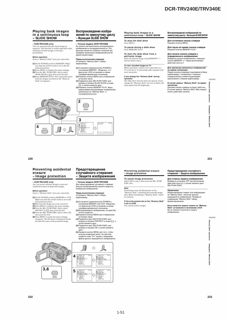
1-51
DCR-TRV240E/TRV340E
220
Playing back imagesin a continuous loop– SLIDE SHOW
– DCR-TRV340E onlyYou can automatically play back images insequence. This function is useful especially whenchecking recorded images or during apresentation.
Before operationInsert a “Memory Stick” into your camcorder.
(1) Set the POWER switch to MEMORY. Makesure that the LOCK switch is set to the left(unlock) position.
(2) Press MENU to display the menu settings.(3) Turn the SEL/PUSH EXEC dial to select
SLIDE SHOW in , then press the dial.(4) Press MEMORY PLAY. Your camcorder plays
back the images recorded on the “MemoryStick” in sequence.
2
4
MENU
PLAY
3MEMORY SET STILL SET MOVIE SET PRINT MARK PROTECT SLIDE SHOW FILE NO. DELETE ALL FORMAT RETURN[MENU] : END
READY
SLIDE SHOW100 – 0021
21/40
[M PLAY] : START [MENU] : END
Воспроизведение изобра-жений по замкнутому циклу– Функция SLIDE SHOW
– Только модель DCR-TRV340EВы можете автоматически воспроизводитьизображения в последовательности. Этафункция является особенно полезной припроверке записанных изображений или вовремя презентации.
Перед выполнением операцииУстановите “Memory Stick” в Вашувидеокамеру.
(1) Установите переключатель POWER вположение MEMORY. Убедитесь, чтофиксатор LOCK установлен в левом(незафиксированном) положении.
(2) Нажмите кнопку MENU для отображенияустановок меню.
(3) Поверните диск SEL/PUSH EXEC длявыбора установки SLIDE SHOW в опции
, а затем нажмите диск.(4) Нажмите кнопку MEMORY PLAY. Ваша
видеокамера воспроизведет изображения,записанные на “Memory Stick”, впоследовательности.
221
“Mem
ory Stick ” o
peratio
ns О
пер
аци
и с “M
emo
ry Stick”
Playing back images in acontinuous loop – SLIDE SHOW
To stop the slide showPress MENU.
To pause during a slide showPress MEMORY PLAY.
To start the slide show from aparticular imageSelect the desired image using MEMORY +/–buttons before step 2.
To view recorded images on TVBefore operation, connect your camcorder to aTV with the A/V connecting cable supplied withyour camcorder.
If you change the “Memory Stick” duringoperationThe slide show function does not operate. If youchange the “Memory Stick”, be sure to follow thesteps again from the beginning.
Воспроизведение изображений позамкнутому циклу – Функция SLIDE SHOW
Для остановки показа слайдовНажмите кнопку MENU.
Для паузы во время показа слайдовНажмите кнопку MEMORY PLAY.
Для начала показа слайдов сопределенного изображенияВыберите нужное изображение с помощьюкнопок MEMORY +/– перед выполнениемдействий пункта 2.
Для просмотра записанных изображенийна экране телевизораПеред началом операции подсоедините Вашувидеокамеру к телевизору с помощьюсоединительного кабеля аудио/видео,прилагаемого к Вашей видеокамере.
В случае замены “Memory Stick” во времяпросмотраФункция показа слайдов не будет работать.В случае замены “Memory Stick” Вам следуетначать действия сначала.
222
– DCR-TRV340E onlyYou can protect selected images, to preventaccidental erasure of important images.
Before operationInsert a “Memory Stick” into your camcorder.
(1) Set the POWER switch to MEMORY or VCR.Make sure that the LOCK switch is set to theleft (unlock) position.
(2) Play back the image you want to protect.(3) Press MENU to display the menu settings.(4) Turn the SEL/PUSH EXEC dial to select
PROTECT in , then press the dial.(5) Turn the SEL/PUSH EXEC dial to select ON,
then press the dial.(6) Press MENU to make the menu settings
disappear. The - mark is displayed besidethe data file name of the protected image.
Preventing accidentalerasure– Image protection
3,6
MENU
4
5
MEMORY SET STILL SET MOVIE SET PRINT MARK PROTECT SLIDE SHOW FILE NO. DELETE ALL FORMAT RETURN
OFF
21/40
[MENU] : END
MEMORY SET STILL SET MOVIE SET PRINT MARK PROTECT SLIDE SHOW FILE NO. DELETE ALL FORMAT RETURN
ONOFF
21/40
[MENU] : END
MEMORY SET STILL SET MOVIE SET PRINT MARK PROTECT SLIDE SHOW FILE NO. DELETE ALL FORMAT RETURN
ONOFF
21/40
[MENU] : END
MEMORY SET STILL SET MOVIE SET PRINT MARK PROTECT SLIDE SHOW FILE NO. DELETE ALL FORMAT RETURN
ON
21/40
[MENU] : END
– Только модель DCR-TRV340EДля предотвращения случайного стиранияважных изображений Вы можете защититьвыбранные изображения.
Перед выполнением операцииУстановите “Memory Stick” в Вашувидеокамеру.
(1) Установите переключатель POWER вположение MEMORY или VCR. Убедитесь,что фиксатор LOCK установлен в левом(незафиксированном) положении.
(2) Воспроизведите изображение, которое Выхотите защитить.
(3) Нажмите кнопку MENU для отображенияустановок меню.
(4) Поверните диск SEL/PUSH EXEC длявыбора установки PROTECT в опции , азатем нажмите диск.
(5) Поверните диск SEL/PUSH EXEC длявыбора установки ON, а затем нажмитедиск.
(6) Нажмите кнопку MENU для того, чтобыисчезла индикация меню. На дисплеепоявится знак “-” рядом с названиемфайла данных защищенного изображения.
Предотвращениеслучайного стирания– Защита изображения
223
“Mem
ory Stick ” o
peratio
ns О
пе
ра
ци
и с
“Me
mo
ry S
tick
”
Preventing accidental erasure– Image protection
To cancel image protectionSelect OFF in step 5, then press the SEL/PUSHEXEC dial.
NoteFormatting erases all information on the“Memory Stick”, including the protected imagedata. Before formatting a “Memory Stick”, checkits contents.
If the write-protect tab on the “Memory Stick”is set to LOCKYou cannot protect images.
Предотвращение случайногостирания – Защита изображения
Для отмены защиты изображенияВыберите установку OFF при выполнениидействий пункта 5, а затем нажмите дискSEL/PUSH EXEC.
ПримечаниеФорматирование стирает всю информациюна “Memory Stick”, включая данныезащищенного изображения. Проверьтесодержание “Memory Stick” передформатированием.
Если лепесток защиты записи на “MemoryStick” установлен в положение LOCKВы не сможете выполнить защитуизображения.

1-52
DCR-TRV240E/TRV340E
224
– DCR-TRV340E onlyYou can delete images stored in a “MemoryStick.” You can delete all images or only selectedimages.
Deleting selected images
Before operationInsert a “Memory Stick” into your camcorder.
(1) Set the POWER switch to MEMORY or VCR.Make sure that the LOCK switch is set to theleft (unlock) position.
(2) Play back the image you want to delete.(3) Press MEMORY DELETE. “DELETE?”
appears on the screen.(4) Press MEMORY DELETE again. The selected
image is deleted.
To cancel deleting an imagePress MEMORY – in step 4.
To delete an image displayed on theindex screenPress MEMORY +/– to move the B indicator tothe image and follow steps 3 and 4.
Notes•You cannot delete a protected image. To delete
a protected image, first cancel image protection.•Once you delete an image, you cannot restore
it. Before deleting an image, carefully check theimage.
If the write-protect tab on the “Memory Stick”is set to LOCKYou cannot delete images.
Deleting images– DELETE
– Только модель DCR-TRV340EВы можете удалить изображения,сохраненные на “Memory Stick”. Вы можетеудалить все изображения или тольковыбранные изображения.
Удаление выбранныхизображений
Перед выполнением операцииУстановите “Memory Stick” в Вашувидеокамеру.
(1) Установите переключатель POWER вположение MEMORY или VCR. Убедитесь,что фиксатор LOCK установлен в левом(незафиксированном) положении.
(2) Воспроизведите изображение, которое Выхотите удалить.
(3) Нажмите кнопку MEMORY DELETE. Наэкране появится индикация “DELETE?”
(4) Нажмите кнопку MEMORY DELETE ещераз. Выбранное изображение будетудалено.
Для отмены удаления изображенияНажмите кнопку MEMORY – при выполнениидействий пункта 4.
Для удаления изображения,отображаемого на индексном экранеНажмите кнопку MEMORY +/– дляперемещения индикатора B к изображению иследуйте действиям пунктов 3 и 4.
Примечания•Вы не сможете удалить защищенное
изображение. Для удаления защищенногоизображения, сначала отмените защитуизображения.
•После удаления изображения Вы не сможе-те восстановить его. Проверьте изображе-ния внимательно, прежде чем удалить их.
Если лепесток защиты записи на “MemoryStick” установлен в положение LOCKВы не можете удалить изображения.
Удаление изображений– Функция DELETE
3DELETE DELETE?
DELETE100–0021
[DELETE] : DEL [–] : CANCEL
21/40
225
“Mem
ory Stick ” o
peratio
ns О
пер
аци
и с “M
emo
ry Stick”
Deleting images – DELETE
Deleting all images
You can delete all unprotected images in the“Memory Stick.”
Before operationInsert a “Memory Stick” into your camcorder.
(1) Set the POWER switch to MEMORY. Makesure that the LOCK switch is set to the left(unlock) position.
(2) Press MENU to display the menu settings.(3) Turn the SEL/PUSH EXEC dial to select
DELETE ALL in , then press the dial.(4) Turn the SEL/PUSH EXEC dial to select OK,
then press the dial. OK changes to EXECUTE.(5) Turn the SEL/PUSH EXEC dial to select
EXECUTE, then press the dial. DELETINGappears on the screen. When all unprotectedimages are deleted, COMPLETE is displayed.
2
MENU
3
4
5
MEMORY SET STILL SET MOVIE SET PRINT MARK PROTECT SLIDE SHOW FILE NO. DELETE ALL FORMAT RETURN
READY
[MENU] : END
MEMORY SET STILL SET MOVIE SET PRINT MARK PROTECT SLIDE SHOW FILE NO. DELETE ALL FORMAT RETURN
RETURNOK
[MENU] : END
MEMORY SET STILL SET MOVIE SET PRINT MARK PROTECT SLIDE SHOW FILE NO. DELETE ALL FORMAT RETURN
RETURNOK
[MENU] : END
MEMORY SET STILL SET MOVIE SET PRINT MARK PROTECT SLIDE SHOW FILE NO. DELETE ALL FORMAT RETURN
RETURNEXECUTE
[MENU] : END
MEMORY SET STILL SET MOVIE SET PRINT MARK PROTECT SLIDE SHOW FILE NO. DELETE ALL FORMAT RETURN
DELETING
[MENU] : END
MEMORY SET STILL SET MOVIE SET PRINT MARK PROTECT SLIDE SHOW FILE NO. DELETE ALL FORMAT RETURN
COMPLETE
[MENU] : END
Удаление изображений – ФункцияDELETE
Удаление всех изображений
Вы можете удалить все незащищенныеизображения на “Memory Stick”.
Перед выполнением операцииУстановите “Memory Stick” в Вашувидеокамеру.
(1) Установите переключатель POWER вположение MEMORY. Убедитесь, чтофиксатор LOCK установлен в левом(незафиксированном) положении.
(2) Нажмите кнопку MENU для отображенияустановок меню.
(3) Поверните диск SEL/PUSH EXEC длявыбора установки DELETE ALL в опции
, а затем нажмите диск.(4) Поверните диск SEL/PUSH EXEC для
выбора установки OK, а затем нажмитедиск. Индикация OK изменится наиндикацию EXECUTE.
(5) Поверните диск SEL/PUSH EXEC длявыбора установки EXECUTE, а затемнажмите диск. На экране появитсяиндикация DELETING. Когда всенезащищенные изображения будутудалены, на дисплее появится индикацияCOMPLETE.
226
Deleting images – DELETE
To cancel deleting all the images inthe “Memory Stick”Select RETURN in step 4, then press the SEL/PUSH EXEC.
While DELETING appearsDo not turn the POWER switch or press anybuttons.
If the write-protect tab on the “Memory Stick”is set to LOCKYou cannot delete images.
Удаление изображений – ФункцияDELETE
Для отмены удаления всехизображений на “Memory Stick”Выберите установку RETURN привыполнении действий пункта 4, а затемнажмите диск SEL/PUSH EXEC.
Во время отображения индикацииDELETINGНе изменяйте положение переключателяPOWER и не нажимайте каких-либо кнопок.
Если лепесток защиты записи на “MemoryStick” установлен в положение LOCKВы не можете удалить изображения.
227
“Mem
ory Stick ” o
peratio
ns О
пер
аци
и с “M
emo
ry Stick”
Writing a print mark– PRINT MARK
– DCR-TRV340E onlyYou can specify a recorded still image to printout by writing a print mark. This function isuseful for printing out still images later.Your camcorder conforms to the DPOF (DigitalPrint Order Format) standard for specifying stillimages to print out.
Before operationInsert a “Memory Stick” into your camcorder.
(1) Set the POWER switch to MEMORY or VCR.Make sure that the LOCK switch is set to theleft (unlock) position.
(2) Play back the still image you want to write aprint mark on.
(3) Press MENU to display the menu settings.(4) Turn the SEL/PUSH EXEC dial to select
PRINT MARK in , then press the dial.(5) Turn the SEL/PUSH EXEC dial to select ON,
then press the dial.(6) Press MENU to make the menu settings
disappear. The mark is displayed besidethe data file name of the image with a printmark.
3,6
MENU
4
5
MEMORY SET STILL SET MOVIE SET PRINT MARK PROTECT SLIDE SHOW FILE NO. DELETE ALL FORMAT RETURN
OFF
[MENU] : END
MEMORY SET STILL SET MOVIE SET PRINT MARK PROTECT SLIDE SHOW FILE NO. DELETE ALL FORMAT RETURN
ONOFF
[MENU] : END
MEMORY SET STILL SET MOVIE SET PRINT MARK PROTECT SLIDE SHOW FILE NO. DELETE ALL FORMAT RETURN
ONOFF
[MENU] : END
MEMORY SET STILL SET MOVIE SET PRINT MARK PROTECT SLIDE SHOW FILE NO. DELETE ALL FORMAT RETURN
ON
[MENU] : END
Запись знака печати– Функция PRINT MARK
– Только модель DCR-TRV340EВы можете указать записанные неподвижныеизображения для распечатки, помечая ихзнаками печати. Эта функция являетсяполезной для распечатки неподвижныхизображений позднее.Ваша видеокамера соответствует стандартуDPOF (цифровой формат порядка печати)для указания неподвижных изображений дляраспечатки.
Перед выполнением операцииУстановите “Memory Stick” в Вашувидеокамеру.
(1) Установите переключатель POWER вположение MEMORY или VCR. Убедитесь,что фиксатор LOCK установлен в левом(незафиксированном) положении.
(2) Воспроизведите неподвижноеизображение, на котором Вы хотитезаписать знак печати.
(3) Нажмите кнопку MENU для отображенияустановок меню.
(4) Поверните диск SEL/PUSH EXEC длявыбора установки PRINT MARK в опции
, а затем нажмите диск.(5) Поверните диск SEL/PUSH EXEC для
выбора установки ON, а затем нажмитедиск.
(6) Нажмите кнопку MENU для того, чтобыисчезла индикация меню. Рядом сназванием файла данных изображения сознаком печати будет отображаться знак
.
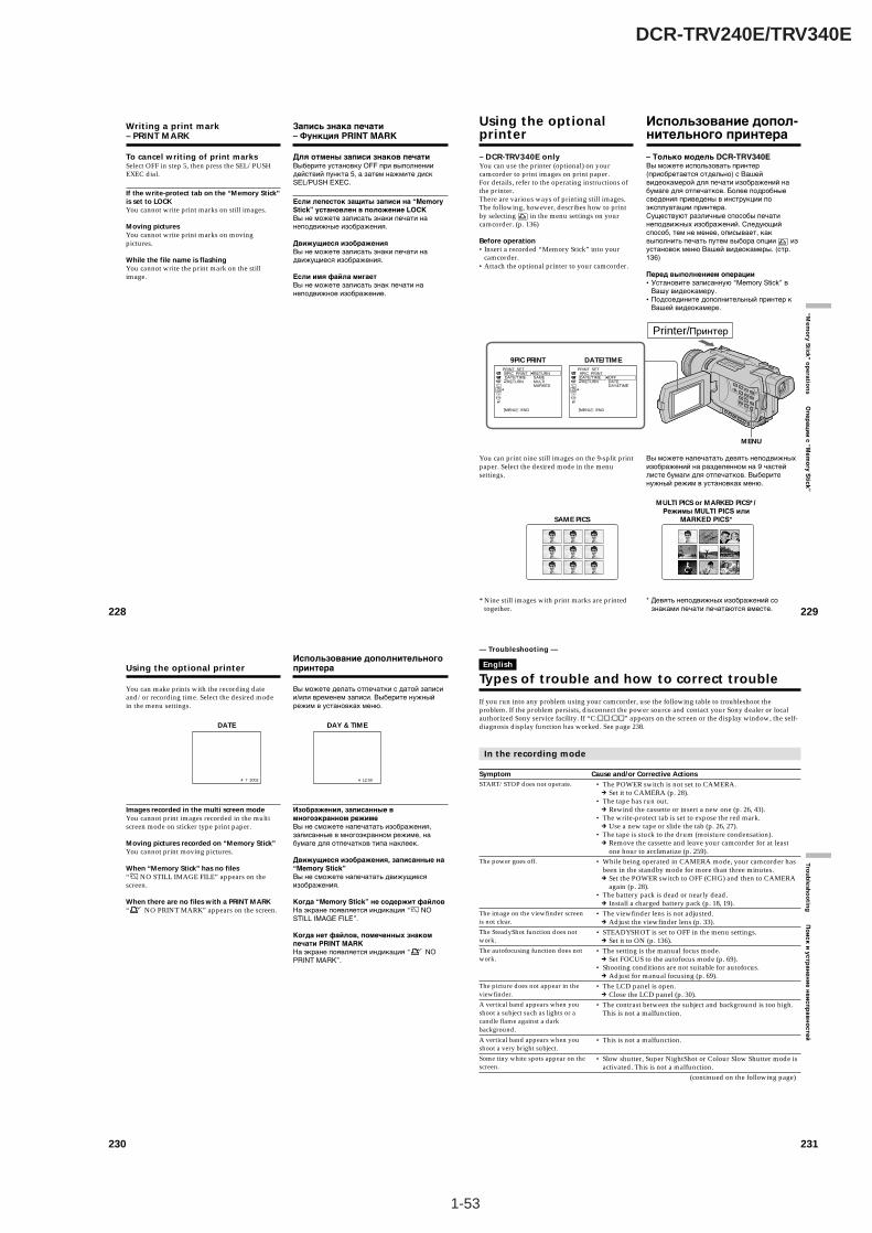
1-53
DCR-TRV240E/TRV340E
228
Writing a print mark– PRINT MARK
To cancel writing of print marksSelect OFF in step 5, then press the SEL/PUSHEXEC dial.
If the write-protect tab on the “Memory Stick”is set to LOCKYou cannot write print marks on still images.
Moving picturesYou cannot write print marks on movingpictures.
While the file name is flashingYou cannot write the print mark on the stillimage.
Запись знака печати– Функция PRINT MARK
Для отмены записи знаков печатиВыберите установку OFF при выполнениидействий пункта 5, а затем нажмите дискSEL/PUSH EXEC.
Если лепесток защиты записи на “MemoryStick” установлен в положение LOCKВы не можете записать знаки печати нанеподвижные изображения.
Движущиеся изображенияВы не можете записать знаки печати надвижущиеся изображения.
Если имя файла мигаетВы не можете записать знак печати нанеподвижное изображение.
229
“Mem
ory Stick ” o
peratio
ns О
пер
аци
и с “M
emo
ry Stick”
– DCR-TRV340E onlyYou can use the printer (optional) on yourcamcorder to print images on print paper.For details, refer to the operating instructions ofthe printer.There are various ways of printing still images.The following, however, describes how to printby selecting in the menu settings on yourcamcorder. (p. 136)
Before operation•Insert a recorded “Memory Stick” into your
camcorder.•Attach the optional printer to your camcorder.
You can print nine still images on the 9-split printpaper. Select the desired mode in the menusettings.
* Nine still images with print marks are printedtogether.
Using the optionalprinter
– Только модель DCR-TRV340EВы можете использовать принтер(приобретается отдельно) с Вашейвидеокамерой для печати изображений набумаге для отпечатков. Более подробныесведения приведены в инструкции поэксплуатации принтера.Существуют различные способы печатинеподвижных изображений. Следующийспособ, тем не менее, описывает, каквыполнить печать путем выбора опции изустановок меню Вашей видеокамеры. (стр.136)
Перед выполнением операции•Установите записанную “Memory Stick” в
Вашу видеокамеру.•Подсоедините дополнительный принтер к
Вашей видеокамере.
Вы можете напечатать девять неподвижныхизображений на разделенном на 9 частейлисте бумаги для отпечатков. Выберитенужный режим в установках меню.
* Девять неподвижных изображений сознаками печати печатаются вместе.
Использование допол-нительного принтера
MULTI PICS or MARKED PICS*/Режимы MULTI PICS или
MARKED PICS*SAME PICS
MENU
9PIC PRINT DATE/TIME
Printer/
DATEPRINT SET 9PIC PRINT DATE/TIME RETURN
RETURNSAMEMULTIMARKED
[MENU] : END
PRINT SET 9PIC PRINT DATE/TIME RETURN
OFFDATEDAY&TIME
[MENU] : END
230
Using the optional printer
You can make prints with the recording dateand/or recording time. Select the desired modein the menu settings.
Images recorded in the multi screen modeYou cannot print images recorded in the multiscreen mode on sticker type print paper.
Moving pictures recorded on “Memory Stick”You cannot print moving pictures.
When “Memory Stick” has no files“ NO STILL IMAGE FILE” appears on thescreen.
When there are no files with a PRINT MARK“ NO PRINT MARK” appears on the screen.
Использование дополнительногопринтера
Вы можете делать отпечатки с датой записии/или временем записи. Выберите нужныйрежим в установках меню.
Изображения, записанные вмногоэкранном режимеВы не сможете напечатать изображения,записанные в многоэкранном режиме, набумаге для отпечатков типа наклеек.
Движущиеся изображения, записанные на“Memory Stick”Вы не сможете напечатать движущиесяизображения.
Когда “Memory Stick” не содержит файловНа экране появляется индикация “ NOSTILL IMAGE FILE”.
Когда нет файлов, помеченных знакомпечати PRINT MARKНа экране появляется индикация “ NOPRINT MARK”.
4 7 2002
DATE DAY & TIME
4 12:00
231
Trou
blesh
oo
ting
По
ис
к и
ус
тра
не
ни
е н
еи
сп
ра
вн
ос
тей
If you run into any problem using your camcorder, use the following table to troubleshoot theproblem. If the problem persists, disconnect the power source and contact your Sony dealer or localauthorized Sony service facility. If “C:ss:ss” appears on the screen or the display window, the self-diagnosis display function has worked. See page 238.
In the recording mode
Symptom Cause and/or Corrective Actions• The POWER switch is not set to CAMERA.
c Set it to CAMERA (p. 28).• The tape has run out.
c Rewind the cassette or insert a new one (p. 26, 43).• The write-protect tab is set to expose the red mark.
c Use a new tape or slide the tab (p. 26, 27).• The tape is stuck to the drum (moisture condensation).
c Remove the cassette and leave your camcorder for at leastone hour to acclimatize (p. 259).
• While being operated in CAMERA mode, your camcorder hasbeen in the standby mode for more than three minutes.c Set the POWER switch to OFF (CHG) and then to CAMERA
again (p. 28).• The battery pack is dead or nearly dead.
c Install a charged battery pack (p. 18, 19).• The viewfinder lens is not adjusted.
c Adjust the viewfinder lens (p. 33).• STEADYSHOT is set to OFF in the menu settings.
c Set it to ON (p. 136).• The setting is the manual focus mode.
c Set FOCUS to the autofocus mode (p. 69).• Shooting conditions are not suitable for autofocus.
c Adjust for manual focusing (p. 69).• The LCD panel is open.
c Close the LCD panel (p. 30).• The contrast between the subject and background is too high.
This is not a malfunction.
• This is not a malfunction.
• Slow shutter, Super NightShot or Colour Slow Shutter mode isactivated. This is not a malfunction.
(continued on the following page)
— Troubleshooting —
English
Types of trouble and how to correct trouble
START/STOP does not operate.
The power goes off.
The image on the viewfinder screenis not clear.
The SteadyShot function does notwork.
The autofocusing function does notwork.
The picture does not appear in theviewfinder.
A vertical band appears when youshoot a subject such as lights or acandle flame against a darkbackground.
A vertical band appears when youshoot a very bright subject.
Some tiny white spots appear on thescreen.
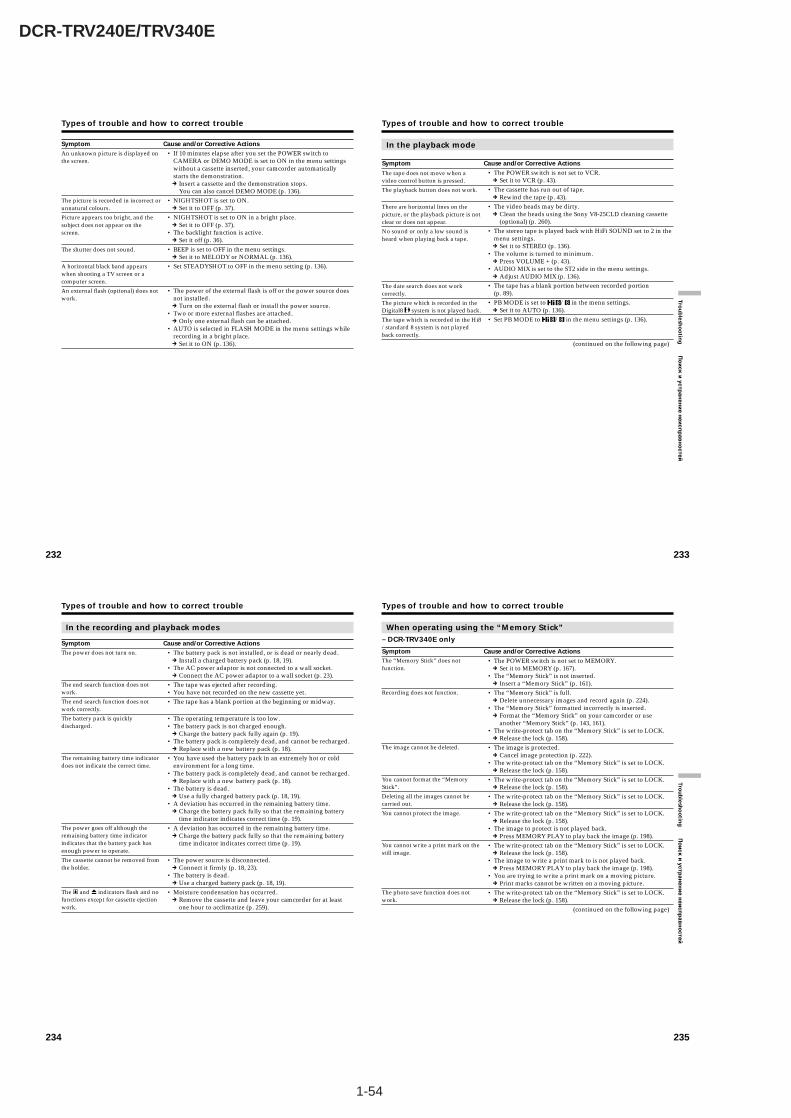
1-54
DCR-TRV240E/TRV340E
232
Types of trouble and how to correct trouble
Symptom Cause and/or Corrective Actions• If 10 minutes elapse after you set the POWER switch to
CAMERA or DEMO MODE is set to ON in the menu settingswithout a cassette inserted, your camcorder automaticallystarts the demonstration.c Insert a cassette and the demonstration stops.
You can also cancel DEMO MODE (p. 136).• NIGHTSHOT is set to ON.
c Set it to OFF (p. 37).• NIGHTSHOT is set to ON in a bright place.
c Set it to OFF (p. 37).• The backlight function is active.
c Set it off (p. 36).• BEEP is set to OFF in the menu settings.
c Set it to MELODY or NORMAL (p. 136).• Set STEADYSHOT to OFF in the menu setting (p. 136).
• The power of the external flash is off or the power source doesnot installed.c Turn on the external flash or install the power source.
• Two or more external flashes are attached.c Only one external flash can be attached.
• AUTO is selected in FLASH MODE in the menu settings whilerecording in a bright place.c Set it to ON (p. 136).
An unknown picture is displayed onthe screen.
The picture is recorded in incorrect orunnatural colours.
Picture appears too bright, and thesubject does not appear on thescreen.
The shutter does not sound.
A horizontal black band appearswhen shooting a TV screen or acomputer screen.
An external flash (optional) does notwork.
233
Trou
blesh
oo
ting
По
иск
и устр
анен
ие н
еисп
рав
но
стей
Types of trouble and how to correct trouble
In the playback mode
Symptom Cause and/or Corrective Actions• The POWER switch is not set to VCR.
c Set it to VCR (p. 43).• The cassette has run out of tape.
c Rewind the tape (p. 43).• The video heads may be dirty.
c Clean the heads using the Sony V8-25CLD cleaning cassette(optional) (p. 260).
• The stereo tape is played back with HiFi SOUND set to 2 in themenu settings.c Set it to STEREO (p. 136).
• The volume is turned to minimum.c Press VOLUME + (p. 43).
• AUDIO MIX is set to the ST2 side in the menu settings.c Adjust AUDIO MIX (p. 136).
• The tape has a blank portion between recorded portion(p. 89).
• PB MODE is set to / in the menu settings.c Set it to AUTO (p. 136).
• Set PB MODE to / in the menu settings (p. 136).
(continued on the following page)
The tape does not move when avideo control button is pressed.
The playback button does not work.
There are horizontal lines on thepicture, or the playback picture is notclear or does not appear.
No sound or only a low sound isheard when playing back a tape.
The date search does not workcorrectly.
The picture which is recorded in theDigital8 system is not played back.
The tape which is recorded in the Hi8/standard 8 system is not playedback correctly.
234
Types of trouble and how to correct trouble
In the recording and playback modes
Symptom Cause and/or Corrective Actions• The battery pack is not installed, or is dead or nearly dead.
c Install a charged battery pack (p. 18, 19).• The AC power adaptor is not connected to a wall socket.
c Connect the AC power adaptor to a wall socket (p. 23).• The tape was ejected after recording.• You have not recorded on the new cassette yet.• The tape has a blank portion at the beginning or midway.
• The operating temperature is too low.• The battery pack is not charged enough.
c Charge the battery pack fully again (p. 19).• The battery pack is completely dead, and cannot be recharged.
c Replace with a new battery pack (p. 18).• You have used the battery pack in an extremely hot or cold
environment for a long time.• The battery pack is completely dead, and cannot be recharged.
c Replace with a new battery pack (p. 18).• The battery is dead.
c Use a fully charged battery pack (p. 18, 19).• A deviation has occurred in the remaining battery time.
c Charge the battery pack fully so that the remaining batterytime indicator indicates correct time (p. 19).
• A deviation has occurred in the remaining battery time.c Charge the battery pack fully so that the remaining battery
time indicator indicates correct time (p. 19).
• The power source is disconnected.c Connect it firmly (p. 18, 23).
• The battery is dead.c Use a charged battery pack (p. 18, 19).
• Moisture condensation has occurred.c Remove the cassette and leave your camcorder for at least
one hour to acclimatize (p. 259).
The power does not turn on.
The end search function does notwork.
The end search function does notwork correctly.
The battery pack is quicklydischarged.
The remaining battery time indicatordoes not indicate the correct time.
The power goes off although theremaining battery time indicatorindicates that the battery pack hasenough power to operate.
The cassette cannot be removed fromthe holder.
The % and Z indicators flash and nofunctions except for cassette ejectionwork.
235
Trou
blesh
oo
ting
По
иск
и устр
анен
ие н
еисп
рав
но
стей
Types of trouble and how to correct trouble
When operating using the “Memory Stick”– DCR-TRV340E only
Symptom Cause and/or Corrective Actions• The POWER switch is not set to MEMORY.
c Set it to MEMORY (p. 167).• The “Memory Stick” is not inserted.
c Insert a “Memory Stick” (p. 161).• The “Memory Stick” is full.
c Delete unnecessary images and record again (p. 224).• The “Memory Stick” formatted incorrectly is inserted.
c Format the “Memory Stick” on your camcorder or useanother “Memory Stick” (p. 143, 161).
• The write-protect tab on the “Memory Stick” is set to LOCK.c Release the lock (p. 158).
• The image is protected.c Cancel image protection (p. 222).
• The write-protect tab on the “Memory Stick” is set to LOCK.c Release the lock (p. 158).
• The write-protect tab on the “Memory Stick” is set to LOCK.c Release the lock (p. 158).
• The write-protect tab on the “Memory Stick” is set to LOCK.c Release the lock (p. 158).
• The write-protect tab on the “Memory Stick” is set to LOCK.c Release the lock (p. 158).
• The image to protect is not played back.c Press MEMORY PLAY to play back the image (p. 198).
• The write-protect tab on the “Memory Stick” is set to LOCK.c Release the lock (p. 158).
• The image to write a print mark to is not played back.c Press MEMORY PLAY to play back the image (p. 198).
• You are trying to write a print mark on a moving picture.c Print marks cannot be written on a moving picture.
• The write-protect tab on the “Memory Stick” is set to LOCK.c Release the lock (p. 158).
(continued on the following page)
The “Memory Stick” does notfunction.
Recording does not function.
The image cannot be deleted.
You cannot format the “MemoryStick”.
Deleting all the images cannot becarried out.
You cannot protect the image.
You cannot write a print mark on thestill image.
The photo save function does notwork.
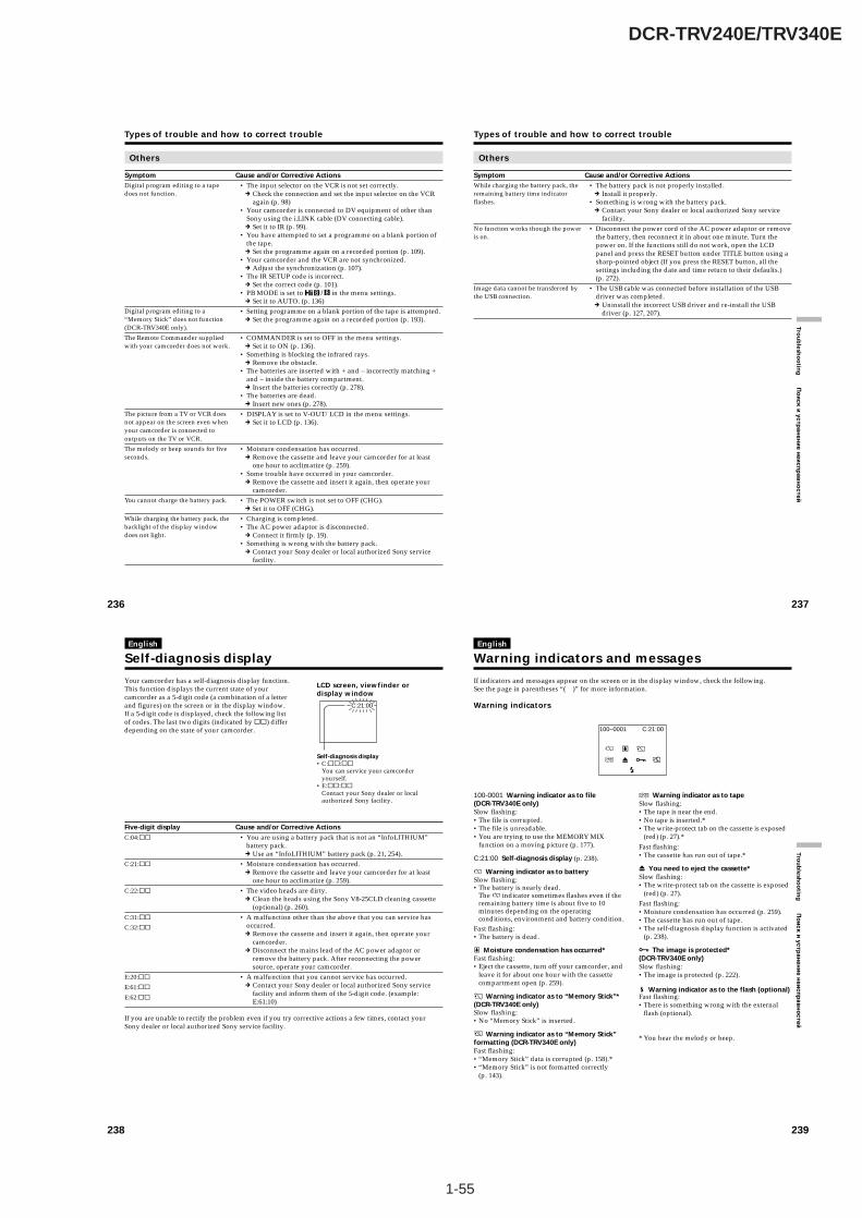
1-55
DCR-TRV240E/TRV340E
236
Types of trouble and how to correct trouble
Others
Symptom Cause and/or Corrective Actions• The input selector on the VCR is not set correctly.
c Check the connection and set the input selector on the VCRagain (p. 98)
• Your camcorder is connected to DV equipment of other thanSony using the i.LINK cable (DV connecting cable).c Set it to IR (p. 99).
• You have attempted to set a programme on a blank portion ofthe tape.c Set the programme again on a recorded portion (p. 109).
• Your camcorder and the VCR are not synchronized.c Adjust the synchronization (p. 107).
• The IR SETUP code is incorrect.c Set the correct code (p. 101).
• PB MODE is set to / in the menu settings.c Set it to AUTO. (p. 136)
• Setting programme on a blank portion of the tape is attempted.c Set the programme again on a recorded portion (p. 193).
• COMMANDER is set to OFF in the menu settings.c Set it to ON (p. 136).
• Something is blocking the infrared rays.c Remove the obstacle.
• The batteries are inserted with + and – incorrectly matching +and – inside the battery compartment.c Insert the batteries correctly (p. 278).
• The batteries are dead.c Insert new ones (p. 278).
• DISPLAY is set to V-OUT/LCD in the menu settings.c Set it to LCD (p. 136).
• Moisture condensation has occurred.c Remove the cassette and leave your camcorder for at least
one hour to acclimatize (p. 259).• Some trouble have occurred in your camcorder.
c Remove the cassette and insert it again, then operate yourcamcorder.
• The POWER switch is not set to OFF (CHG).c Set it to OFF (CHG).
• Charging is completed.• The AC power adaptor is disconnected.
c Connect it firmly (p. 19).• Something is wrong with the battery pack.
c Contact your Sony dealer or local authorized Sony servicefacility.
Digital program editing to a tapedoes not function.
Digital program editing to a“Memory Stick” does not function(DCR-TRV340E only).
The Remote Commander suppliedwith your camcorder does not work.
The picture from a TV or VCR doesnot appear on the screen even whenyour camcorder is connected tooutputs on the TV or VCR.
The melody or beep sounds for fiveseconds.
You cannot charge the battery pack.
While charging the battery pack, thebacklight of the display windowdoes not light.
237
Trou
blesh
oo
ting
По
иск
и устр
анен
ие н
еисп
рав
но
стей
Others
Symptom Cause and/or Corrective Actions• The battery pack is not properly installed.
c Install it properly.• Something is wrong with the battery pack.
c Contact your Sony dealer or local authorized Sony servicefacility.
• Disconnect the power cord of the AC power adaptor or removethe battery, then reconnect it in about one minute. Turn thepower on. If the functions still do not work, open the LCDpanel and press the RESET button under TITLE button using asharp-pointed object (If you press the RESET button, all thesettings including the date and time return to their defaults.)(p. 272).
• The USB cable was connected before installation of the USBdriver was completed.c Uninstall the incorrect USB driver and re-install the USB
driver (p. 127, 207).
While charging the battery pack, theremaining battery time indicatorflashes.
No function works though the poweris on.
Image data cannot be transferred bythe USB connection.
Types of trouble and how to correct trouble
238
English
Self-diagnosis display
Your camcorder has a self-diagnosis display function.This function displays the current state of yourcamcorder as a 5-digit code (a combination of a letterand figures) on the screen or in the display window.If a 5-digit code is displayed, check the following listof codes. The last two digits (indicated by ss) differdepending on the state of your camcorder.
LCD screen, viewfinder ordisplay window
Self-diagnosis display• C:ss:ss
You can service your camcorderyourself.
• E:ss:ss
Contact your Sony dealer or localauthorized Sony facility.
C:21:00
Five-digit display Cause and/or Corrective Actions• You are using a battery pack that is not an “InfoLITHIUM”
battery pack.c Use an “InfoLITHIUM” battery pack (p. 21, 254).
• Moisture condensation has occurred.c Remove the cassette and leave your camcorder for at least
one hour to acclimatize (p. 259).• The video heads are dirty.
c Clean the heads using the Sony V8-25CLD cleaning cassette(optional) (p. 260).
• A malfunction other than the above that you can service hasoccurred.c Remove the cassette and insert it again, then operate your
camcorder.c Disconnect the mains lead of the AC power adaptor or
remove the battery pack. After reconnecting the powersource, operate your camcorder.
• A malfunction that you cannot service has occurred.c Contact your Sony dealer or local authorized Sony service
facility and inform them of the 5-digit code. (example:E:61:10)
C:04:ss
C:21:ss
C:22:ss
C:31:ss
C:32:ss
E:20:ss
E:61:ss
E:62:ss
If you are unable to rectify the problem even if you try corrective actions a few times, contact yourSony dealer or local authorized Sony service facility.
239
Trou
blesh
oo
ting
По
ис
к и
ус
тра
не
ни
е н
еи
сп
ра
вн
ос
тей
If indicators and messages appear on the screen or in the display window, check the following.See the page in parentheses “( )” for more information.
Warning indicators
English
Warning indicators and messages
C:21:00100–0001
100-0001 Warning indicator as to file(DCR-TRV340E only)Slow flashing:•The file is corrupted.•The file is unreadable.•You are trying to use the MEMORY MIX
function on a moving picture (p. 177).
C:21:00 Self-diagnosis display (p. 238).
E Warning indicator as to batterySlow flashing:•The battery is nearly dead.
The E indicator sometimes flashes even if theremaining battery time is about five to 10minutes depending on the operatingconditions, environment and battery condition.
Fast flashing:•The battery is dead.
% Moisture condensation has occurred*Fast flashing:•Eject the cassette, turn off your camcorder, and
leave it for about one hour with the cassettecompartment open (p. 259).
Warning indicator as to “Memory Stick”*(DCR-TRV340E only)Slow flashing:•No “Memory Stick” is inserted.
Warning indicator as to “Memory Stick”formatting (DCR-TRV340E only)Fast flashing:•“Memory Stick” data is corrupted (p. 158).*•“Memory Stick” is not formatted correctly
(p. 143).
Q Warning indicator as to tapeSlow flashing:•The tape is near the end.•No tape is inserted.*•The write-protect tab on the cassette is exposed
(red) (p. 27).*Fast flashing:•The cassette has run out of tape.*
Z You need to eject the cassette*Slow flashing:•The write-protect tab on the cassette is exposed
(red) (p. 27).Fast flashing:•Moisture condensation has occurred (p. 259).•The cassette has run out of tape.•The self-diagnosis display function is activated
(p. 238).
- The image is protected*(DCR-TRV340E only)Slow flashing:•The image is protected (p. 222).
Warning indicator as to the flash (optional)Fast flashing:•There is something wrong with the external
flash (optional).
* You hear the melody or beep.
1-56
DCR-TRV240E/TRV340E
240
Warning indicators and messages
Warning messages•CLOCK SET Set the date and time (p. 24).
•FOR “InfoLITHIUM” Use an “InfoLITHIUM” battery pack (p. 254).BATTERY ONLY
•Q Z TAPE END The cassette has run out of tape.*
•Q NO TAPE Insert a cassette tape.*
• CLEANING CASSETTE The video heads are dirty (p. 260). (The x indicator and “CLEANING CASSETTE” message appear one after another on thescreen.)
•COPY INHIBIT You tried to record a picture that has a copyright control signal*(p. 252).
• FULL** The “Memory Stick” is full* (p. 171).
• -** The write-protect tab on the “Memory Stick” is set to LOCK*(p. 158).
• NO FILE** No still image is recorded on the “Memory Stick”* (p. 199).
• NO MEMORY STICK** No “Memory Stick” is inserted.*
• AUDIO ERROR** You are trying to record an image with sound that cannot berecorded by your camcorder on “Memory Stick”* (p. 190).
• MEMORY STICK ERROR** The “Memory Stick” data is corrupted* (p. 161).
• FORMAT ERROR** Check the type of formatting* (p. 143).
• - DIRECTORY ERROR** The “Memory Stick” has more than one directory such as 100msdcf*(p. 199).
• PLAY ERROR** The image is distorted and cannot be played back.*
• REC ERROR** Check the input signal before retrying recording* (p. 184, 192).
• NO PRINT MARK** You selected MARKED in 9PIC PRINT in the menu settings using an“Memory Stick” contains no image with a print mark* (p. 230).
• NO STILL IMAGE FILE** You selected MULTI in 9PIC PRINT in the menu settings using a“Memory Stick” contains no still image* (p. 230).
•DELETING** You have pressed PHOTO during deleting all images on “MemoryStick.”*
•FORMATTING** You have pressed PHOTO during formatting a “Memory Stick.”*
• NOW CHARGING Charging an external flash (optional) does not work correctly.*
* You hear the melody or beep.
** DCR-TRV340E only
251
Ad
ditio
nal In
form
ation
До
по
лн
ите
ль
на
я и
нф
ор
ма
ци
я— Additional Information —
Digital8 system,recording and playback
What is the “Digital8 system”?This video system has been developed to enabledigital recording to Hi8 /Digital8 videocassette .
Usable cassette tapesWe recommend using Hi8 /Digital8 videocassette.*The recording time when you use your Digital8
system camcorder on Hi8 /standard 8 tape is 2/3 the recording time when using theconventional Hi8 /standard 8 systemcamcorder. (90 minutes of recording timebecomes 60 minutes in the SP mode.)* If you use standard 8 tape, be sure to play
back the tape on this camcorder. Mosaic patternnoise may appear when you play back standard8 tape on other VCRs (including other DCR-TRV240E/TRV340E).
NoteTapes recorded in the Digital8 system cannotbe played back on Hi8 /standard 8 (analog) system machine.
is a trademark. is a trademark.
is a trademark.
Playback system
The Digital8 system or Hi8 /standard 8 system is automatically detected before the tapeis played back.During playback of tapes recorded in the Hi8
/standard 8 system, digital signals areoutput as the image signals from the DV IN/OUT jack.
— Дополнительная информация —
Система Digital8 , записьи воспроизведение
Что такое “Система Digital8 ”?Эта видеосистема разработана дляобеспечения цифровой записи навидеокассеты Hi8 Hi /Digital8 .
Используемые кассетные лентыРекомендуется использование видеокассетHi8 Hi /Digital8 .*Время записи при использовании Вами лентыHi8 /standard 8 в Вашей видеокамере,работающей в системе Digital8 , составляет2/3 времени записи при использованииобычной видеокамеры, работающей всистеме Hi8 /standard 8 . (90 минутвремени записи будут составлять 60 минут врежиме SP.)* Если Вы используете стандартную ленту 8
, обязательно воспроизводите ее наВашей видеокамере. При воспроизведениистандартной ленты 8 на другихвидеокамерах (включая другиевидеокамеры DCR-TRV240E/TRV340E)могут возникать искажения типа мозаики.
ПримечаниеЛенты, записанные в системе Digital8 , немогут воспроизводиться на устройствах,работающих в системе (аналоговой) Hi8 /standard 8 .
является фирменным знаком. является фирменным знаком.
является фирменным знаком.
Система воспроизведения
Система Digital8 или Hi8 /standard 8 определяется автоматически передвоспроизведением ленты.Во время воспроизведения лент, записанныхв системе Hi8 /standard 8 , цифровыесигналы выводятся как сигналы изображенияиз гнезда DV IN/OUT.
252
Digital8 system, recording andplayback
Display during automatic detection of systemThe Digital8 system or Hi8 /standard 8 system is automatically detected, and theplayback system is automatically switched to.During switching of systems, the screen turnsblue, and the following displays appear on thescreen. A hissing noise also sometimes can beheard.
t / : During switching from Digital8 to Hi8 /standard 8
/ t : During switching from Hi8 /standard 8 to Digital8
When you play back
Playing back an NTSC-recorded tapeYou can play back tapes recorded in the NTSCvideo system on the LCD screen, if the tape isrecorded in the SP mode.
Copyright signal
When you play backUsing any other video camera recorder, youcannot record on a tape that has recordedcopyright control signals for copyright protectionof software which is played back on yourcamcorder.
When you recordYou cannot record software on your camcorderthat contains copyright control signals forcopyright protection of software.COPY INHIBIT appears on the LCD screen, inthe viewfinder or on the TV screen if you try torecord such software. Your camcorder does notrecord copyright control signals on the tapewhen it records.
Система Digital8 , запись ивоспроизведение
Индикация во время автоматическогоопределения системыСистема Digital8 или Hi8 /standard 8 определяется автоматически, и системавоспроизведения автоматическипереключается. Во время переключениясистем экран становится синим, и на экранепоявляется следующая индикация. Иногдаможет быть слышен также шипящий шум.
Индикация t / : во времяпереключения системы с Digital8 на Hi8
/standard 8 .Индикация / t : во времяпереключения системы с Hi8 /standard 8
на Digital8 .
При воспроизведении
Воспроизведение лент, записанных всистеме NTSCВы можете воспроизводить на экране ЖКДленты, записанные в видеосистеме NTSC,если лента записана в режиме SP.
Сигнал авторского права
При воспроизведенииИспользуя любую другую видеокамеру, Вы несможете выполнить запись на ленте, накоторую были записаны сигналы управленияавторским правом для защиты авторскогоправа программного обеспечения, котороевоспроизводится на Вашей видеокамере.
При записиВы не сможете записать программноеобеспечение на Вашей видеокамере, котороесодержит сигналы управления авторскимправом для защиты авторского правапрограммного обеспечения.На экране ЖКД, в видоискателе или наэкране телевизора появится индикацияCOPY INHIBIT, если Вы попытаетесь записатьтакое программное обеспечение. Вашавидеокамера не записывает сигналыуправления авторским правом на ленту,когда она выполняет запись.
253
Ad
ditio
nal In
form
ation
До
по
лн
ите
ль
на
я и
нф
ор
ма
ци
я
Digital8 system, recording andplayback
When you playback a dualsound track tape
When you use tapes recorded in theDigital8 systemWhen you play back a Digital8 system tapewhich is dubbed from a dual sound track taperecorded in the DV system, set HiFi SOUND tothe desired mode in the menu settings (p. 136).
Sound from speakerHiFi Sound Playing back Playing back a dualMode a stereo tape sound track tape
STEREO StereoMain sound and subsound
1 Lch Main sound2 Rch Sub sound
When you use a tape recorded in theHi8/standard 8 systemWhen you play back a dual sound track taperecorded in an AFM HiFi stereo system, set HiFiSOUND to the desired mode in the menu settings(p. 136).
Sound from speakerHiFi Sound Playing back Playing back a dualMode a stereo tape sound track tape
STEREO StereoMain sound and subsound
1 Monaural Main sound
2Unnatural
Sub soundSound
You cannot record dual sound programmes onyour camcorder.
Система Digital8 , запись ивоспроизведение
При воспроизведении ленты сдвойной звуковой дорожкой
При использовании лент, записанныхв системе Digital8 Если Вы воспроизводите ленту системыDigital8 , которая перезаписана с ленты сдвойной звуковой дорожкой, записанной всистеме цифрового видео DV, установите внужный режим опцию HiFi SOUND вустановках меню (стр. 136).
Звук от динамика
Режим Воспроизведение ВоспроизведениеHiFi Sound стереофонической ленты с двойной
ленты звуковой дорожкой
Стереофонический Основной звукSTEREO звук и вспомога-
тельный звук
1 Левый канал Основной звук
2 Правый канал Вспомогательныйзвук
При использовании ленты,записанной в системе Hi8/standard 8Если Вы воспроизводите ленту с двойнойзвуковой дорожкой, записанную встереофонической системе AFM HiFi,установите в нужный режим опцию HiFiSOUND в установках меню (стр. 136).
Звук от динамика
Режим Воспроизведение ВоспроизведениеHiFi Sound стереофонической ленты с двойной
ленты звуковой дорожкой
Стереофонический Основной звукSTEREO звук и вспомога-
тельный звук
1 Монофонический Основной звукзвук
2 Неестественный Вспомогательныйзвук звук
Вы не можете записывать программы сдвойным звучанием на Вашей видеокамере.
1-57
DCR-TRV240E/TRV340E
254
About the “InfoLITHIUM”battery pack
What is the “InfoLITHIUM” batterypack?The “InfoLITHIUM” battery pack is a lithium-ionbattery pack that has functions forcommunicating information related to operatingconditions between your camcorder and an ACadaptor/charger (optional).The “InfoLITHIUM” battery pack calculates thepower consumption according to the operatingconditions of your camcorder, and displays theremaining battery time in minutes.
Charging the battery pack•Be sure to charge the battery pack before you
start using your camcorder.•We recommend charging the battery pack in an
ambient temperature of between10°C to 30°C (50°F to 86°F) until the backlight ofthe display window goes out, indicating thatthe battery pack is fully charged. If you chargethe battery outside of this temperature range,you may not be able to efficiently charge thebattery pack.
•After charging is completed, either disconnectthe cable from the DC IN jack on yourcamcorder or remove the battery pack.
Effective use of the battery pack•Battery pack performance decreases in low-
temperature surroundings. So, the time that thebattery pack can be used is shorter in coldplaces. We recommend the following to ensurelonger battery pack use:– Put the battery pack in a pocket to warm it up,
and insert it in your camcorder immediatelybefore you start taking shots.
– Use the large-capacity battery pack (NP-FM70/QM71/FM90/FM91/QM91, optional).
•Frequently using the LCD panel or frequentlyoperating playback, fast-forward or rewindwears out the battery pack faster. Werecommend using the large-capacity batterypack (NP-FM70/QM71/FM90/FM91/QM91,optional).
•Be sure to turn the POWER switch to OFF(CHG) when not taking shots or playing backon your camcorder. The battery pack is alsoconsumed when your camcorder is in thestandby mode or playback is paused.
О батарейном блоке“InfoLITHIUM”
Что такое батарейный блок“InfoLITHIUM”?Батарейный блок “InfoLITHIUM” представляетсобой литиево-ионный батарейный блок,который оснащен функциями обменаданными, связанными с условиями работы,между Вашей видеокамерой и сетевымадаптером/зарядным устройствомпеременного тока (приобретается отдельно).Батарейный блок “InfoLITHIUM” вычисляетпотребление энергии в зависимости отусловий работы Вашей видеокамеры иотображает оставшееся время зарядабатарейного блока в минутах.
Зарядка батарейного блока•Перед началом использования видеокамеры
удостоверьтесь, что батарейный блок заряжен.•Рекомендуется заряжать батарейный блок
при температуре окружающей среды от10°C до 30°С до тех пор, пока неотключится задняя подсветка окошкадисплея, означающая, что батарейный блокзаряжен полностью. Если Вы заряжаетебатарейный блок при температуре, непопадающей в указанный выше диапазон,Вы не сможете эффективно зарядитьбатарейный блок.
•После завершения зарядки либо отсоединитекабель от гнезда DC IN Вашей видеокамеры,либо снимите батарейный блок.
Эффективное использованиебатарейного блока•Производительность батарейного блока падает
в условиях низких температур. Поэтому время,в течение которого можно пользоватьсябатарейным блоком, уменьшается в холоднойместности. Для более продолжительногоиспользования батарейного блокарекомендуется следующее:– Помещайте батарейный блок во
внутренний карман, чтобы нагреть его, иустанавливайте его на видеокамерунепосредственно перед съемкой.
– Используйте батарейный блок большойемкости (NP-FM70/QM71/FM90/FM91/QM91, приобретается отдельно).
•Частое использование экрана ЖКД иличастое применение воспроизведения,ускоренной перемотки вперед или назадбыстрее разряжает батарейный блок.Рекомендуется использовать батарейныйблок большой емкости (NP-FM70/QM71/FM90/FM91/QM91, приобретается отдельно).
•Обязательно устанавливайтепереключатель POWER в положение OFF(CHG), в то время, когда Вы не производитесъемку и не выполняете воспроизведениена Вашей видеокамере. Заряд батарейногоблока также расходуется, когда Вашавидеокамера находится в режиме ожиданияили паузы воспроизведения.
257
Ad
ditio
nal In
form
ation
До
по
лн
ите
ль
на
я и
нф
ор
ма
ци
я
About i.LINK
i.LINK baud rate
i.LINK’s maximum baud rate varies according tothe equipment. Three maximum baud rates aredefined:
S100 (approx. 100 Mbps*)S200 (approx. 200 Mbps)S400 (approx. 400 Mbps)
The baud rate is listed under “Specifications” inthe operating instructions of each equipment. It isalso indicated near the i.LINK jack on someequipment.The maximum baud rate of equipment on whichit is not indicated such as this unit is “S100”.When units are unit is connected to equipmenthaving a different maximum baud rate, the baudrate sometimes differs from the indicated baudrate.
* What is “Mbps”?Mbps stands for megabits per second, or theamount of data that can be sent or received inone second. For example, a baud rate of 100Mbps means that 100 megabits of data can besent in one second.
i.LINK functions on this unit
For details on how to dub when this unit isconnected to other video equipment having DVjacks, see page 95, 184.This unit can also be connected to other i.LINK(DV) compatible equipment made by SONY (e.g.VAIO series personal computer) other than videoequipment.Before connecting this unit to a personalcomputer, make sure that application softwaresupported by this unit is already installed on thepersonal computer.For details on precautions when connecting thisunit, also refer to the operating instructions of theequipment to be connected.
Required i.LINK cable
Use the Sony i.LINK 4-pin-to-4-pin cable (duringDV dubbing).
i.LINK and are trademarks.
О стандарте i.LINK
Скорость передачи данныхi.LINK в бодах
Максимальная скорость передачи данныхi.LINK в бодах отличается согласноаппаратуре. Определены три максимальныескорости передачи данных в бодах:
S100 (прибл. 100 Мбит/с*)S200 (прибл. 200 Мбит/с)S400 (прибл. 400 Мбит/с)
Скорость передачи данных в бодах указана вразделе “Технические характеристики”инструкции по эксплуатации каждого аппарата.Она также указывается вблизи разъема i.LINKна некоторых аппаратах.Максимальной скоростью передачи данных вбодах для аппаратов, на которых она неуказана, таких, как данный аппарат, является“S100”. Если аппараты подсоединяются коборудованию с различной максимальнойскоростью передачи данных в бодах, скоростьпередачи данных в бодах иногда отличается отуказанной скорости передачи данных в бодах.
* Что такое “Мбит/с”?Мбит/с обозначает мегабит в секунду, иликоличество данных, которые могут бытьпосланы или приняты за одну секунду.Например, скорость передачи данных в бодах100 Мбит/с обозначает, что 100 мегабитданных могут быть посланы за одну секунду.
Функции i.LINK на этом аппаратеДля получения более подробной информации оперезаписи при подсоединении данного аппара-та к другой видеоаппаратуре, имеющей гнездамицифрового видеосигнала DV, см. стр. 95, 184.Данный аппарат также может бытьподсоединен к другой совместимой с i.LINK(цифровой видеосигнал DV) аппаратуре,произведенной SONY (например,персональные компьютеры серии VAIO) и неявляющейся видеоаппаратурой.Перед подсоединением этого аппарата кперсональному компьютеру убедитесь, что наперсональном компьютере уже установленопрограммное обеспечение, поддерживаемоеданным аппаратом.Для получения более подробной информациио мерах предосторожности при подсоеди-нении данного аппарата, обращайтесь такжек руководствам по эксплуатации аппаратуры,которую нужно подсоединить.
Требуемый кабель i.LINKИспользуйте кабель 4 штырька-4 штырькаi.LINK Sony (во время перезаписи цифровоговидеосигнала DV).i.LINK и являются фирменными знаками.
255
Ad
ditio
nal In
form
ation
До
по
лн
ите
ль
на
я и
нф
ор
ма
ци
я
About the “InfoLITHIUM” batterypack
•Have spare battery packs handy for two orthree times the expected recording time, andmake a trial recordings before taking the actualrecording.
•Do not expose the battery pack to water. Thebattery pack is not water-resistant.
Remaining battery time indicator•If the power may go off although the remaining
battery time indicator indicates that the batterypack has enough power to operate, charge thebattery pack fully again so that the indicationon the remaining battery time indicator iscorrect. Note, however, that the correct batteryindication sometimes will not be restored if it isused in high temperatures for a long time or leftin a fully charged state, or the battery pack isfrequently used. Regard the remaining batterytime indication as the approximate shootingtime.
•The E mark indicating that there is littleremaining battery time sometimes flashesdepending on the operating conditions orambient temperature and environment even ifthe remaining battery time is about five to 10minutes.
How to store the battery pack•If the battery pack is not used for a long time,
do the following procedure once per year tomaintain proper function.1. Fully charge the battery.2. Discharge on your electronic equipment.3. Remove the battery from the equipment and
store it in a dry, cool place.•To use the battery pack up on your camcorder,
leave your camcorder in the standby modeuntil the power goes off without a cassetteinserted.
Battery life•The battery life is limited. Battery capacity
drops little by little as you use it more andmore, and as time passes. When the availablebattery time is shortened considerably, aprobable cause is that the battery pack hasreached the end of its life. Buy a new batterypack.
•The battery life varies according to how it isstored and operating conditions andenvironment for each battery pack.
О батарейном блоке “InfoLITHIUM”
•Держите под рукой запасные батарейныеблоки с зарядом, в 2-3 раза большим, чеможидаемое время съемки, и проводитепробную съемку перед тем, как выполнитьреальную съемку.
•Не смачивайте батарейный блок. Батарейныйблок не является водонепроницаемым.
Индикатор времени оставшегосязаряда батарейного блока•Если питание может выключиться, хотя
индикатор оставшегося времени зарядабатарейного блока показываетдостаточный для работы заряд батарейногоблока, зарядите батарейный блокполностью еще раз, чтобы отображениеиндикатора оставшегося времени зарядабатарейного блока стало правильным.Заметьте, тем не менее, что точнаяиндикация времени заряда батарейногоблока иногда не будет восстанавливаться,если он длительное время использовалсяпри высоких температурах или былоставлен в полностью заряженномсостоянии, или при частом использованиибатарейного блока. Считайте индикациюоставшегося времени заряда батарейногоблока приблизительным временем съемки.
•Иногда метка E, указывающая на то, чтовремени заряда батарейного блокаосталось мало, мигает в зависимости отусловий эксплуатации или окружающейтемпературы и среды, даже если зарядаосталось от пяти до 10 минут.
Как хранить батарейный блок•Даже если батарейный блок не
используется длительное время, проводитеследующую процедуру один раз в год дляподдержания надлежащегофункционирования батарейного блока.1. Полностью зарядите батарейный блок.2. Разрядите его на Вашей электронной
аппаратуре.3. Извлеките батарейный блок из аппаратуры
храните его в сухом, прохладном месте.•Для того, чтобы полностью разрядить
батарейный блок на Вашей видеокамере,оставьте Вашу видеокамеру в режимеожидания без вставленной кассеты, показаряд батарейного блока не исчерпается.
Срок службы батарейного блока•Срок службы батарейного блока ограничен.
Емкость батарейного блока мало-помалупадает, по мере того, как Вы с течениемвремени используете его все больше и больше.Когда доступное время заряда батарейногоблока значительно сократится, возможнойпричиной является то, что срок службыбатарейного блока закончился. Пожалуйста,приобретите новый батарейный блок.
•Срок службы батарейного блокаизменяется в соответствии с тем, как онхранится, а также в зависимости от условийэксплуатации и окружающей среды длякаждого батарейного блока.
256
About i.LINK
The DV jack on this unit is an i.LINK-compliantDV input/output jack. This section describes thei.LINK standard and its features.
What is “i.LINK”?i.LINK is a digital serial interface for handlingdigital video, digital audio and other data in twodirections between equipment having the i.LINKjack, and for controlling other equipment.i.LINK-compatible equipment can be connectedby a single i.LINK cable. Possible applications areoperations and data transactions with variousdigital AV equipment.When two or more i.LINK-compatible equipmentare connected to this unit in a daisy chain,operations and data transactions are possiblewith not only the equipment that this unit isconnected to but also with other devices via thedirectly connected equipment.Note, however, that the method of operationsometimes varies according to the characteristicsand specifications of the equipment to beconnected, and that operations and datatransactions are sometimes not possible on someconnected equipment.
NoteNormally, only one piece of equipment can beconnected to this unit by the i.LINK cable (DVcable). When connecting this unit to i.LINK-compatible equipment having two or morei.LINK jacks (DV jacks), refer to the operatinginstructions of the equipment to be connected.
About the name “i.LINK”
i.LINK is a more familiar term for IEEE 1394 datatransport bus proposed by SONY, and is atrademark approved by many corporations.IEEE 1394 is an international standardstandardized by the Institute of Electrical andElectronic Engineers.
О стандарте i.LINK
Гнездо цифрового видеосигнала DV наданном аппарате является гнездом входа/выхода цифрового видеосигнала DV,совместимым со стандартом i.LINK. Этотраздел описывает стандарт i.LINK и егохарактеристики.
Что такое “i.LINK”?i.LINK представляет из себя цифровойдвунаправленный последовательныйинтерфейс для передачи цифровоговидеосигнала, цифрового аудиосигнала идругих данных между аппаратурой, имеющейгнездо i.LINK, и для управления другойаппаратурой.i.LINK-совместимая аппаратура может бытьподключена одним кабелем i.LINK.Возможные применения включают обработкуи передачу данных с помощью различнойцифровой аудио/видео аппаратуры.Если два или более i.LINK-совместимыхаппарата подсоединены к данному аппаратупоследовательной цепочкой, возможныобработка и передача данных не только нааппаратуре, к которой подсоединен данныйаппарат, но также и на других устройствахчерез напрямую подсоединенную аппаратуру.Заметьте, тем не менее, что метод работыиногда отличается согласно особенностям итехническим характеристикам аппаратуры,которую нужно подсоединить, и что обра-ботка и передача данных иногда невозможнына некоторых подсоединенных аппаратах.
ПримечаниеОбычно только один аппарат может бытьподсоединен к данному аппарату с помощьюкабеля i.LINK (соединительного кабеляцифрового видеосигнала DV). Приподсоединении данного аппарата к i.LINK-совместимой аппаратуре с двумя или болеегнездами i.LINK (гнездами цифровоговидеосигнала DV), обращайтесь круководству по эксплуатации аппаратуры,которую нужно подсоединить.
О названии “i.LINK”
i.LINK является более узнаваемымопределением для шины транспорта данныхIEEE 1394, предложенным SONY, и являетсяфирменным знаком, утвержденным многимикорпорациями. IEEE 1394 являетсямеждународным стандартом, стандартизо-ванным Институтом инженеров по электро-технике и радиоэлектронике.

1-58
DCR-TRV240E/TRV340E
258
Using your camcorderabroad
Using your camcorder abroad
You can use your camcorder in any country orarea with the AC power adaptor supplied withyour camcorder within 100 V to 240 V AC, 50/60Hz.
Your camcorder is a PAL system basedcamcorder. If you want to view the playbackpicture on a TV, it must be a PAL system basedTV with VIDEO/AUDIO input jack.The following shows TV colour systems usedoverseas.
PAL systemAustralia, Austria, Belgium, China, CzechRepublic, Denmark, Finland, Germany, GreatBritain, Holland, Hong Kong, Italy, Kuwait,Malaysia, New Zealand, Norway, Portugal,Singapore, Slovak Republic, Spain, Sweden,Switzerland, Thailand, etc.
PAL-M systemBrazil
PAL-N systemArgentina, Paraguay, Uruguay
NTSC systemBahama Islands, Bolivia, Canada, CentralAmerica, Chile, Colombia, Ecuador, Jamaica,Japan, Korea, Mexico, Peru, Surinam, Taiwan, thePhilippines, the U.S.A., Venezuela, etc.
SECAM systemBulgaria, France, Guyana, Hungary, Iran, Iraq,Monaco, Poland, Russia, Ukraine, etc.
Simple setting of clock by timedifference
You can easily set the clock to the local time bysetting a time difference. Select WORLD TIME inthe menu settings. See page 136 for moreinformation.
Использование Вашейвидеокамеры за границей
Использование Вашейвидеокамеры за границей
Вы можете использовать Вашу сетевоговидеокамеру в любой стране или области спомощью адаптера переменного тока,прилагаемого к Вашей видеокамере, которыйможно использовать в пределах от 100 В до240 В переменного тока с частотой 50/60 Гц.
Ваша видеокамера основана на системе PAL.Если Вы хотите просмотретьвоспроизводимое изображение нателевизоре, то это должен быть телевизор,основанный на системе PAL, с входнымгнездом VIDEO/AUDIO.Ниже приведены системы цветноготелевидения, используемые за рубежом.
Система PALАвстралия, Австрия, Бельгия,Великобритания, Германия, Голландия,Гонконг, Дания, Испания, Италия, Китай,Кувейт, Малайзия, Новая Зеландия,Норвегия, Португалия, Сингапур, СловацкаяРеспублика, Таиланд, Финляндия, ЧешскаяРеспублика, Швейцария, Швеция и т.д.
Система PAL-MБразилия
Система PAL-NАргентина, Парагвай, Уругвай
Система NTSCБагамские острова, Боливия, Венесуэла,Канада, Колумбия, Корея, Мексика, Перу,Суринам, США, Тайвань, Филиппины,Центральная Америка, Чили, Эквадор,Ямайка, Япония и т.д.
Система SECAMБолгария, Венгрия, Гайана, Ирак, Иран, Монако,Польша, Россия, Украина, Франция и т.д.
Простая установка часов поразнице во времени
Вы можете легко установить часы на местноевремя путем установки разницы во времени.Выберите команду WORLD TIME вустановках меню. Более подробные сведенияприведены на стр. 136.
259
Ad
ditio
nal In
form
ation
До
по
лн
ите
ль
на
я и
нф
ор
ма
ци
яMaintenanceinformation andprecautions
Moisture condensation
If your camcorder is brought directly from a coldplace to a warm place, moisture may condenseinside your camcorder, on the surface of the tape,or on the lens. In this state, the tape may stick tothe head drum and be damaged or yourcamcorder may not operate correctly. If there ismoisture inside your camcorder, the beep soundsand the % indicator flashes. When the Zindicator flashes at the same time, the cassette isinserted in your camcorder. If moisturecondenses on the lens, the indicator will notappear.
If moisture condensation hasoccurredNone of the functions except cassette ejection willwork. Eject the cassette, turn off your camcorder,and leave it for about one hour with the cassettecompartment open. Your camcorder can be usedagain if the % indicator does not appear whenthe power is turned on again.
Note on moisture condensationMoisture may condense when you bring yourcamcorder from a cold place into a warm place(or vice versa) or when you use your camcorderin a hot place as follows:•You bring your camcorder from a ski slope into
a place warmed up by a heating device.•You bring your camcorder from an air-
conditioned car or room into a hot placeoutside.
•You use your camcorder after a squall or ashower.
•You use your camcorder in a high temperatureand humidity place.
How to prevent moisture condensationWhen you bring your camcorder from a coldplace into a warm place, put your camcorder in aplastic bag and tightly seal it. Remove the bagwhen the air temperature inside the plastic baghas reached the surrounding temperature (afterabout one hour).
Информация по уходуза аппаратом и мерыпредосторожности
Конденсация влаги
Если видеокамера принесена прямо изхолодного места в теплое, то внутривидеокамеры, на поверхности ленты или наобъективе может произойти конденсациявлаги. В таком состоянии лента можетприлипнуть к барабану головки и будетповреждена, или же видеокамера не сможетработать надлежащим образом. Если влагапроникла внутрь Вашей видеокамеры, топрозвучит зуммерный сигнал, и будет мигатьиндикатор %. Если в то же самое времябудет мигать индикатор Z, это значит, что ввидеокамеру вставлена кассета. Если влагасконденсировалась на объективе, индикаторпоявляться не будет.
Если произошла конденсация влагиНи одна из функций, кроме выталкиваниякассеты, не будет работать. Извлекитекассету, выключите Вашу видеокамеру иоставьте ее приблизительно на один час соткрытым кассетным отсеком. Если приповторном включении питания индикатор %не появится, Вы можете снова пользоватьсявидеокамерой.
Примечание по конденсации влагиВлага может образоваться, если Выпринесете Вашу видеокамеру из холодногоместа в теплое место (или наоборот) иликогда Вы используете Вашу видеокамеру вжарком месте в следующих случаях:•Вы принесли Вашу видеокамеру с лыжного
склона в помещение, где функционируетобогреватель.
•Вы вынесли Вашу видеокамеру изавтомобиля или из комнаты с воздушнымкондиционированием в жаркое место наулице.
•Вы используете видеокамеру после шквалаили ливня.
•Вы используете Вашу видеокамеру в оченьжарком и влажном месте.
Как предотвратить конденсацию влагиЕсли видеокамера принесена из холодногоместа в теплое место, положите видеокамерув полиэтиленовый пакет и надежно закройтеего. Выньте видеокамеру из полиэтиленовогопакета, когда температура воздуха внутрипакета достигнет температуры окружающеговоздуха (приблизительно через один час).
260
Maintenance information
Cleaning the video headsTo ensure normal recording and clear pictures,clean the video heads.
When you playback/record in the Digital8 systemThe video head may be dirty when:•Mosaic-pattern noise appears on the playback
picture.•Playback pictures do not move.•Playback pictures are hardly visible.•Playback pictures do not appear.•The x indicator and “ CLEANING
CASSETTE” message appear one after another.
When you play back in the Hi8/Standard 8(analog) systemThe video head may be dirty when:•Playback pictures contain noise.•Playback pictures are hardly visible.•Playback pictures do not appear.
If the above problem occurs, clean the videoheads with the Sony V8-25CLD cleaning cassette(optional). Check the picture and if the aboveproblem persists, repeat cleaning.
Cleaning the LCD screenIf fingerprints or dust make the LCD screen dirty,we recommend using the LCD Cleaning Kit(optional) to clean the LCD screen.
Maintenance information andprecautions
Информация по уходу за аппаратом имеры предосторожности
Информация по уходу зааппаратом
Очистка видеоголовокДля обеспечения нормальной записи ичеткого изображения следует периодическиочищать видеоголовки.
При воспроизведении/записи в системеDigital8 Видеоголовки, возможно, загрязнены, если:•На воспроизводимом изображении
появляются помехи типа мозаики.•Воспроизводимые изображения не двигаются.•Воспроизводимые изображения плохо
видимы.•Воспроизводимые изображения не
появляются.•Индикатор x и сообщение “ CLEANING
CASSETTE” появляются один за другим.
При воспроизведении в системе(аналоговой) Hi8/standard 8Видеоголовки, возможно, загрязнены, если:•Воспроизводимые изображения содержат
помехи.•Воспроизводимые изображения плохо
видимы.•Воспроизводимые изображения не
появляются.
В случае возникновения указанных вышепроблем, очистите видеоголовки с помощьючистящей кассеты Sony V8-25CLD(приобретается отдельно). Проверьтеизображение и, если описанные вышепроблемы не устранились, повторите чистку.
Очистка экрана ЖКДЕсли отпечатки пальцев или пыль загрязняютэкран ЖКД, рекомендуется воспользоватьсяочистительным набором для ЖКД (приобре-тается отдельно) для очистки экрана ЖКД.
or/или
or/или
261
Ad
ditio
nal In
form
ation
До
по
лн
ите
ль
на
я и
нф
ор
ма
ци
я
Maintenance information andprecautions
Charging the built-inrechargeable battery
Your camcorder is supplied with a built-inrechargeable battery installed to retain the dateand time, etc., regardless of the setting of thePOWER switch. The built-in rechargeable batteryis always charged as long as you are using yourcamcorder. The battery, however, will becomedischarged gradually if you do not use yourcamcorder. It will be completely discharged inabout half a year if you do not use yourcamcorder at all. Even if the built-in rechargeablebattery is not charged, it will not affectcamcorder operation. To retain the date, time,and other information, charge the battery if thebattery is discharged.
Charging the built-in rechargeable battery:•Connect your camcorder to wall socket using
the AC power adaptor supplied with yourcamcorder, and leave your camcorder with thePOWER switch turned off for more than 24hours.
•Or, install a fully charged battery pack in yourcamcorder, and leave your camcorder with thePOWER switch set to OFF (CHG) for more than24 hours.
Зарядка встроеннойперезаряжаемой батарейки
Ваша видеокамера оснащена встроеннойперезаряжаемой батарейкой, установленнойдля того, чтобы поддерживать дату, время ит.д., вне зависимости от установкипереключателя POWER. Встроеннаяперезаряжаемая батарейка всегдазаряжается, когда Вы используете Вашувидеокамеру. Однако, батарейка постепенноразрядится, если Вы не будете использоватьВашу видеокамеру. Она будет полностьюразряжена примерно через полгода, если Вывообще не будете пользоваться Вашейвидеокамерой. Даже если встроеннаяперезаряжаемая батарейка не заряжена, онане повлияет на работу видеокамеры. Чтобыподдерживать дату и время, зарядитебатарейку, если она разрядилась.
Зарядка встроенной перезаряжаемойбатарейки:•Подсоедините Вашу видеокамеру к
электрической сети, используя сетевойадаптер переменного тока, прилагаемый кВашей видеокамере, и оставьте Вашувидеокамеру с выключеннымпереключателем POWER более, чем на 24часа.
•Или установите полностью заряженныйбатарейный блок в Вашу видеокамеру иоставьте Вашу видеокамеру спереключателем POWER, установленным вположение OFF (CHG) более, чем на 24часа.
Информация по уходу за аппаратом имеры предосторожности
1-59
DCR-TRV240E/TRV340E
262
Maintenance information andprecautions
Precautions
Camcorder operation•Operate your camcorder on 7.2 V (battery pack)
or 8.4 V (AC power adaptor).•For DC or AC operation, use the accessories
recommended in these operating instructions.•If any solid object or liquid gets inside the
casing, unplug your camcorder and have itchecked by a Sony dealer before operating itany further.
•Avoid rough handling or mechanical shock. Beparticularly careful of the lens.
•Keep the POWER switch set to OFF (CHG)when you are not using your camcorder.
•Do not wrap your camcorder with a towel, forexample, and operate it. Doing so might causeheat to build up inside.
•Keep your camcorder away from strongmagnetic fields or mechanical vibration. Noisemay appear on the image.
•Do not touch the LCD screen with your fingersor a sharp-pointed object.
•If your camcorder is used in a cold place, aresidual image may appear on the screen. Thisis not a malfunction.
•While using your camcorder, the back of theLCD screen may heat up. This is not amalfunction.
On handling tapes•Do not insert anything into the small holes on
the rear of the cassette. These holes are used tosense the type and thickness of the tape and ifthe recording tab is in or out.
•Do not open the tape protect cover or touch thetape.
Информация по уходу за аппаратом имеры предосторожности
Меры предосторожности
Эксплуатация видеокамеры•Эксплуатируйте видеокамеру при 7,2 В
(батарейный блок) или 8,4 В (сетевойадаптер переменного тока).
•Что касается эксплуатации видеокамеры отпостоянного и переменного тока,используйте принадлежности,рекомендуемые в данной инструкции поэксплуатации.
•Если какой-нибудь твердый предмет илижидкость попали внутрь корпуса,выключите видеокамеру и проверьте ее всервисном центре Sony перед еедальнейшей эксплуатацией.
•Избегайте грубого обращения свидеокамерой или механических ударов.Будьте особенно осторожны с объективом.
•Если видеокамера не используется,установите переключатель POWER вположение OFF (CHG).
•Не заворачивайте Вашу видеокамеру,например, в полотенце, и не эксплуатируйтеее в таком состоянии. В противном случаеможет произойти повышение температурывнутри видеокамеры.
•Держите Вашу видеокамеру подальше отсильных магнитных полей или механическойвибрации. На изображении могут появитьсяпомехи.
•Не прикасайтесь к экрану ЖКД своимипальцами или острыми предметами.
•При эксплуатации Вашей видеокамеры вхолодном месте на экране ЖКД можетпоявляться остаточное изображение. Этоне является неисправностью.
•При эксплуатации Вашей видеокамерызадняя сторона экрана ЖКД можетнагреваться. Это не являетсянеисправностью.
Обращение с лентами•Не вставляйте ничего в маленькие
отверстия на задней стороне кассеты. Этиотверстия используются для определениятипа и толщины ленты, а также дляопределения наличия или отсутствиялепестка защиты записи на ленте.
•Не открывайте защитную крышку ленты ине прикасайтесь к ленте.
263
Ad
ditio
nal In
form
ation
До
по
лн
ите
ль
на
я и
нф
ор
ма
ци
я
Maintenance information andprecautions
Camcorder care•Remove the tape, and periodically turn on the
power, operate the CAMERA and VCR sectionsand play back a tape for about three minuteswhen your camcorder is not to be used for along time.
•Clean the lens with a soft brush to remove dust.If there are fingerprints on the lens, removethem with a soft cloth.
•Clean the camcorder body with a dry soft cloth,or a soft cloth lightly moistened with a milddetergent solution. Do not use any type ofsolvent which may damage the finish.
•Do not let sand get into your camcorder. Whenyou use your camcorder on a sandy beach or ina dusty place, protect it from the sand or dust.Sand or dust may cause your camcorder tomalfunction, and sometimes this malfunctioncannot be repaired.
Connection to your computerWhen inputting the image recorded by Hi8/standard 8 system into Sony VAIOThe Program Capture function of DVgate motiondoesn’t work. To use this function, dub the imageinto a Digital8 or DV tape first, and then inputit into your Sony VAIO.
Информация по уходу за аппаратом имеры предосторожности
Уход за видеокамерой•Вынимайте кассету с лентой и
периодически включайте питание,оперируйте устройствами CAMERA и VCR ивоспроизводите ленту в течение примерно3-х минут, если Ваша видеокамера не будетиспользоваться длительное время.
•Очищайте объектив с помощью мягкойкисточки для удаления пыли. Если имеютсяотпечатки пальцев на объективе, удалитеих с помощью мягкой ткани.
•Очищайте корпус видеокамеры с помощьюсухой мягкой ткани или мягкой ткани,слегка смоченной раствором умеренногомоющего средства. Не используйте каких-либо типов растворителей, которые могутповредить отделку.
•Не допускайте попадания песка ввидеокамеру. Если Вы используетевидеокамеру на песчаном пляже или вкаком-либо пыльном месте, предохраняйтеаппарат от песка или пыли. Песок или пыльмогут привести к неисправности аппарата,которая иногда может быть неисправимой.
Подсоединение к Вашему компьютеруПри вводе изображений, записанных всистеме Hi8/standard 8 в персональныйкомпьютер серии Sony VAIO.Функция программного считывания сигналовцифрового видео DV не работает. Дляиспользования этой функции перепишитесначала изображение на ленту в системеDigital8 или DV, а затем введите его в Вашкомпьютер серии Sony VAIO.
264
Maintenance information andprecautions
AC power adaptor•Unplug the unit from the wall socket when you
are not using it for a long time. To disconnectthe mains lead, pull it out by the plug. Neverpull the mains lead itself.
•Do not operate the unit with a damaged cord orif the unit has been dropped or damaged.
•Do not bend the mains lead forcibly, or place aheavy object on it. This will damage the cordand may cause fire or electric shock.
•Prevent metallic objects from coming intocontact with the metal parts of the connectingsection. If this happens, a short may occur andthe unit may be damaged.
•Always keep metal contacts clean.•Do not disassemble the unit.•Do not apply mechanical shock or drop the
unit.•While the unit is in use, particularly during
charging, keep it away from AM receivers andvideo equipment. AM receivers and videoequipment disturb AM reception and videooperation.
•The unit becomes warm during use. This is nota malfunction.
•Do not place the unit in locations that are:– Extremely hot or cold– Dusty or dirty– Very humid– Vibrating
About care and storage of the lens•Wipe the surface of the lens clean with a soft
cloth in the following instances:– When there are fingerprints on the lens
surface– In hot or humid locations– When the lens is used in environments
susceptible to salt such as the seaside•Store the lens in a well-ventilated location
subject to little dirt or dust.
To prevent mold from occurring, periodicallyperform the above.We recommend turning on and operating yourcamcorder about once per month to keep yourcamcorder in an optimum state for a long time.
Информация по уходу за аппаратом имеры предосторожности
Сетевой адаптер переменного тока•Отсоедините аппарат от электрической
сети, если он не используется длительноевремя. Для отсоединения сетевого шнурапотяните его за штекер. Никогда не тянитеза сам шнур.
•Не эксплуатируйте аппарат споврежденным шнуром или же в случае,если аппарат упал или был поврежден.
•Не сгибайте сетевой провод силой и неставьте на него тяжелые предметы. Этоповредит провод и может привести к по-жару или поражению электрическим током.
•Не допускайте соприкосновенияметаллических предметов сметаллическими контактами соединитель-ной пластины. Если это случится, то можетпроизойти короткое замыкание, и аппаратможет быть поврежден.
•Следите за тем, чтобы металлическиеконтакты были чистыми.
•Не разбирайте аппарат.•Не подвергайте аппарат механическим
ударам и не роняйте его.•При использовании аппарата, особенно во
время зарядки, держите его подальше отприемников АМ-радиовещания ивидеоаппаратуры. У приемников АМ-радиовещания и видеоаппаратурынарушается АМ-радиоприем ифункционирование видео.
•В процессе эксплуатации аппарат нагревается.Это является вполне нормальным.
•Не размещайте аппарат в местах:– Чрезмерно жарких или холодных– Пыльных или грязных– Очень влажных– Подверженных вибрации
Об уходе за объективом и о его хранении•Очищайте поверхность объектива мягкой
тканью в следующих случаях:– Если на поверхности объектива есть
отпечатки пальцев– В жарких или влажных местах– При использовании объектива в местах,
допускающих наличие соли, таких, какморское побережье
•Храните объектив в хорошо проветриваемомместе, защищенном от грязи и пыли.
Во избежание появления плесенипериодически выполняйте описанные вышепроцедуры.Рекомендуется включать видеокамеру ипользоваться ею примерно один раз в месяцдля поддержания видеокамеры воптимальном состоянии в течениедлительного времени. 265
Ad
ditio
nal In
form
ation
До
по
лн
ите
ль
на
я и
нф
ор
ма
ци
я
Maintenance information andprecautions
Battery pack•Use only the specified charger or video
equipment with the charging function.•To prevent accident from a short circuit, do not
allow metal objects to come into contact withthe battery terminals.
•Keep the battery pack away from fire.•Never expose the battery pack to temperatures
above 60°C (140°F), such as in a car parked inthe sun or under direct sunlight.
•Keep the battery pack dry.•Do not expose the battery pack to any
mechanical shock.•Do not disassemble nor modify the battery
pack.•Attach the battery pack to the video equipment
securely.•Charging while some capacity remains does not
affect the original battery capacity.
Notes on dry batteriesTo avoid possible damage from battery leakageor corrosion, observe the following:– Be sure to insert the batteries with the + and –
correctly matching the + and – inside thebattery compartment.
– Dry batteries are not rechargeable.– Do not use a combination of new and old
batteries.– Do not use different types of batteries.– Current flows from batteries when you are not
using them for a long time.– Do not use leaking batteries.
If batteries are leaking•Wipe off the liquid in the battery compartment
carefully before replacing the batteries.•If you touch the liquid, wash it off with water.•If the liquid gets into your eyes, wash your eyes
with a lot of water and then consult a doctor.
If any problem occurs, unplug your camcorderand contact your nearest Sony dealer.
Информация по уходу за аппаратом имеры предосторожности
Батарейный блок•Используйте только рекомендуемое
зарядное устройство или видеоаппаратуру сзарядной функцией.
•Для предотвращения несчастного случаяиз-за короткого замыкания не допускайтеконтакта металлических предметов сконтактами батарейного блока.
•Храните батарейный блок вдали от огня.•Никогда не подвергайте батарейный блок
воздействию температур свыше 60°C, нап-ример, в припаркованном под солнцем авто-мобиле или под прямым солнечным светом.
•Следите за тем, чтобы батарейный блокбыл сухим.
•Не подвергайте батарейный блок воздей-ствию каких-либо механических ударов.
•Не разбирайте и не видоизменяйтебатарейный блок.
•Плотно прикрепляйте батарейный блок квидеоаппаратуре.
•Зарядка при некоторой оставшейся емкостине влияет на исходную емкость батарейногоблока.
Примечания о сухих батарейкахВо избежание возможного повреждениявидеокамеры вследствие утечки внутреннеговещества батареек или коррозии соблюдайтеследующее:– При установке батареек соблюдайте
правильную полярность + и – всоответствии с метками + и – внутри отсекадля батареек.
– Сухие батарейки нельзя перезаряжать.– Не используйте новые батарейки вместе со
старыми.– Не используйте батарейки разного типа.– Если батарейки не используются
длительное время, они постепенноразряжаются.
– Не используйте батарейки, которыепотекли.
Если произошла утечка внутреннеговещества батареек•Перед тем, как заменить батарейки,
тщательно протрите остатки жидкости вотсеке для батареек.
•В случае попадания жидкости на кожу,смойте жидкость водой.
•В случае попадания жидкости в глаза,промойте свои глаза большим количествомводы, после чего обратитесь к врачу.
В случае возникновения каких-либо проблем,отключите Вашу видеокамеру от источникапитания и обратитесь в ближайшийсервисный центр Sony.
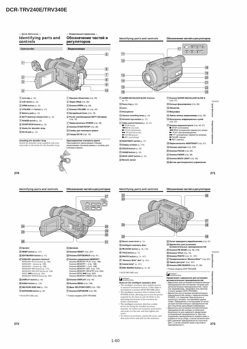
1-60
DCR-TRV240E/TRV340E
270
— Quick Reference —
Identifying parts andcontrols
Camcorder
1 Lens cap (p. 28)
2 LCD screen (p. 28)
3OPEN button (p. 28)
4 VOLUME –/+ button (p. 43)
5 Battery pack (p. 18)
6 BATT (battery) release lever (p. 18)
7 POWER switch (p. 28)
8 START/STOP button (p. 28)
9Hooks for shoulder strap
0DC IN jack (p. 19)
Attaching the shoulder strapAttach the shoulder strap supplied with yourcamcorder to the hooks for the shoulder strap.
4
3
27
8
9
0
1
6
5
— Оперативный справочник —
Обозначение частей ирегуляторов
1Крышка объектива (стр. 28)
2Экран ЖКД (стр. 28)
3Кнопка OPEN (стр. 28)
4Кнопка VOLUME –/+ (стр. 43)
5Батарейный блок (стр. 18)
6 Рычаг освобождения BATT (батареи)(стр. 18)
7Переключатель POWER (стр. 28)
8Кнопка START/STOP (стр. 28)
9Скобы для плечевого ремня
0 Гнездо DC IN (стр. 19)
Присоединение плечевого ремняПрисоедините прилагаемый к Вашейвидеокамере плечевой ремень к скобам дляплечевого ремня.
Видеокамера
271
Qu
ick Referen
ce Оп
ерати
вн
ый
спр
аво
чни
к
Identifying parts and controls
qa SUPER NS/COLOUR SLOW S button(p. 37)
qs Focus ring (p. 69)
qd Lens
qfMicrophone
qg Camera recording lamp (p. 28)
qh Infrared rays emitter (p. 37)
qj Video control buttons (p. 43, 47)x STOP (stop)m REW (rewind)N PLAY (playback)M FF (fast-forward)X PAUSE (pause)z REC (recording)
qkNIGHTSHOT switch (p. 37)
qlDisplay window (p. 279)
w; FOCUS button (p. 69)
wa FADER button (p. 58)
ws BACK LIGHT button (p. 36)
wd Remote sensor
qh
qf
qd
qg
qa
qs
qk
ql
ws
wa
w;
wd
qjREW
REC
FF
PAUSESTOP
PLAY
Обозначение частей и регуляторов
qaКнопка SUPER NS/COLOUR SLOW S(стр. 37)
qsКольцо фокусировки (стр. 69)
qdОбъектив
qfМикрофон
qgЛампа записи видеокамеры (стр. 28)
qhИзлучатель инфракрасных лучей(стр. 37)
qjКнопки видеоконтроля (стр. 43, 47)x STOP (остановка)m REW (ускоренная перемотка назад)N PLAY (воспроизведение)M FF (ускоренная перемотка вперед)X PAUSE (пауза)z REC (запись)
qkПереключатель NIGHTSHOT (стр. 37)
qlОкошко дисплея (стр. 279)
w;Кнопка FOCUS (стр. 69)
waКнопка FADER (стр. 58)
wsКнопка BACK LIGHT (стр. 36)
wdДатчик дистанционного управления
272
Identifying parts and controls
wf Speaker
wg RESET button (p. 237)
wh EDITSEARCH button (p. 41)
wjMEMORY operation buttons*MEMORY PLAY button (p. 198)MEMORY – button (p. 198)MEMORY + button (p. 198)MEMORY MIX button (p. 175)MEMORY DELETE button (p. 224)MPEG u button (p. 202)MEMORY INDEX button (p. 200)
wkDISPLAY button (p. 44)
wlMENU button (p. 136)
e; SEL/PUSH EXEC dial (p. 136)
ea EXPOSURE button (p. 68)
* DCR-TRV340E only
wlwg
wh
wj
wk
e;
ea
wf
PLAYMEMORY
MIX
MEMORY
DELETE MPEG INDEX
Обозначение частей и регуляторов
wfДинамик
wgКнопка RESET (стр. 247)
whКнопка EDITSEARCH (стр. 41)
wjКнопки управления MEMORY*Кнопка MEMORY PLAY (стр. 198)Кнопка MEMORY – (стр. 198)Кнопка MEMORY + (стр. 198)Кнопка MEMORY MIX (стр. 175)Кнопка MEMORY DELETE (стр. 224)Кнопка MPEG u (стр. 202)Кнопка MEMORY INDEX (стр. 200)
wkКнопка DISPLAY (стр. 44)
wlКнопка MENU (стр. 136)
e;Диск SEL/PUSH EXEC (стр. 136)
eaКнопка EXPOSURE (стр. 68)
* Только модель DCR-TRV340E
273
Qu
ick Referen
ce Оп
ерати
вн
ый
спр
аво
чни
к
Identifying parts and controls
es Power zoom lever (p. 31)
ed Intelligent accessory shoe
ef PB ZOOM button (p. 86, 218)
eg TITLE button (p. 75)
eh PHOTO button (p. 51, 167)
ej “Memory Stick” slot* (p. 161)
ekAccess lamp* (p. 161)
el END SEARCH button (p. 41, 48)
* DCR-TRV340E only
Notes on the intelligent accessory shoe•The intelligent accessory shoe supplies power
to optional accessories such as a video light ormicrophone or printer (DCR-TRV340E only).
•The intelligent accessory shoe is linked to thePOWER switch, allowing you to turn the powersupplied by the shoe on and off. Refer to theoperating instructions of the accessory forfurther information.
•The intelligent accessory shoe has a safetydevice for fixing the installed accessorysecurely. To connect an accessory, press downand push it to the end, and then tighten thescrew.
•To remove an accessory, loosen the screw, andthen press down and pull out the accessory.
eg
es
ef ek
eh
el
ej
ed
Обозначение частей и регуляторов
es Рычаг приводного вариобъектива (стр. 31)
edДержатель для установкивспомогательных принадлежностей
efКнопка PB ZOOM (стр. 86, 218)
egКнопка TITLE (стр. 75)
ehКнопка PHOTO (стр. 51, 167)
ej Посадочное место “Memory Stick”* (стр. 161)
ekЛампа доступа* (стр. 161)
elКнопка END SEARCH (стр. 41, 48)
* Только модель DCR-TRV340E
Примечания о держателе для установкивспомогательных принадлежностей•Держатель для установки вспомогательных
принадлежностей поставляет питание длядополнительных принадлежностей, такихкак видеофонарь, микрофон или принтер(только модель DCR-TRV340E).
•Держатель для установки вспомогательныхпринадлежностей связан с переключателемPOWER, что позволяет Вам включать ивыключать питание, поставляемое держа-телем. Обращайтесь к инструкциям по экспл-уатации вспомогательных принадлежностейдля получения дальнейшей информации.
•Держатель для установки вспомогательныхпринадлежностей оснащен устройствомбезопасности для надежного закрепленияустановленной принадлежности. Для под-соединения принадлежности нажмите вниз иподвиньте ее до упора, а затем затяните винт.
•Для удаления принадлежности отпуститевинт, а затем нажмите вниз и вытянитепринадлежность.
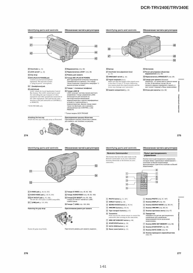
1-61
DCR-TRV240E/TRV340E
274
Identifying parts and controls
rs
ra
r;
rf
rd
rg
r; Viewfinder (p. 33)
ra LOCK switch* (p. 28)
rsGrip strap
rdMIC (PLUG IN POWER) jackConnect an external microphone(optional). This jack also acceptsa “plug-in-power” microphone.
rfi (headphones) jack
rg LANC jackLANC stands for Local Application ControlBus System. The LANC control jack is usedfor controlling the tape transport of videoequipment and other peripherals connected tothe video equipment. This jack has the samefunction as the jack indicated as CONTROL Lor REMOTE.
* DCR-TRV340E only
Attaching the lens capAttach the lens cap to the grip strap as illustrated.
Обозначение частей и регуляторов
r;Видоискатель (стр. 33)
raПереключатель LOCK* (стр. 28)
rs Ремень для захвата
rd Гнездо MIC (PLUG IN POWER)Для подсоединения внешнего микрофона(приобретается отдельно). Это гнездотакже позволяет подключить микрофон “свыключателем питания”.
rf Гнездо i (головные телефоны)
rg Гнездо LANC LANC означает систему канала местногоуправления. Гнездо управления LANCиспользуется для контроля залентопротяжным механизмомвидеоаппаратуры и других периферийныхустройств, подключенных квидеоаппаратуре. Данное гнездо имееттакую же функцию, как и разъемы,обозначенные как CONTROL L илиREMOTE.
* Только модель DCR-TRV340E
Присоединение крышки объективаПрисоедините крышку объектива к ремнюдля захвата, как показано на рисунке.
275
Qu
ick Referen
ce Оп
ерати
вн
ый
спр
аво
чни
к
rj rl
t;
rk
rh
rh Eyecup
rj Viewfinder lens adjustment lever(p. 33)
rkOPEN/EJECT switch (p. 26)
rl Tripod receptacle (base)Make sure that the length of the tripod screwis less than 5.5 mm (7/32 inch). Otherwise,you cannot attach the tripod securely and thescrew may damage your camcorder.
t; Cassette compartment (p. 26)
Identifying parts and controls Обозначение частей и регуляторов
rhНаглазник
rj Рычаг регулировки объективавидоискателя (стр. 33)
rkПереключатель OPEN/EJECT (стр. 26)
rl Гнездо для треноги (базовое)Убедитесь, что длина винта треноги менее5,5 мм. В противном случае, Вы несможете надежно прикрепить треногу, авинт может повредить Вашу видеокамеру.
t;Отсек для кассеты (стр. 26)
276
ta S VIDEO jack (p. 49, 93, 183)
tsAUDIO/VIDEO jack (p. 49, 93, 183)
td DV IN/OUT jack (p. 95, 184)The DV IN/OUT jack is i.LINK compatible.
tf (USB) jack (p. 125, 205)
Fastening the grip strap
Fasten the grip strap firmly.
Identifying parts and controls
ts
ta
tf
td
Обозначение частей и регуляторов
ta Гнездо S VIDEO (стр. 49, 93, 183)
ts Гнездо AUDIO/VIDEO (стр. 49, 93, 183)
td Гнездо DV IN/OUT (стр. 95, 184)Гнездо DV IN/OUT является i.LINK-совместимым
tf Гнездо (USB) (стр. 125, 205)
Пристегивание ремня для захвата
Пристегните ремень для захвата надежно.
277
Qu
ick Referen
ce Оп
ер
ати
вн
ый
сп
ра
во
чн
ик
Remote Commander
The buttons that have the same name on theRemote Commander as on your camcorderfunction identically to the buttons on yourcamcorder.
1 PHOTO button (p. 51, 167)
2 DISPLAY button (p. 44)
3 SEARCH MODE button (p. 89, 91)
4 ./> buttons (p. 89, 91)
5 Tape transport buttons (p. 47)
6 TransmitterPoint toward the remote sensor to control thecamcorder after turning on the camcorder.
7 ZERO SET MEMORY button (p. 88)
8 START/STOP button (p. 28)
9 DATA CODE button (p. 44)
0 Power zoom button (p. 31)
Identifying parts and controls
5
4
3
2
1
0
8
7
6
9
Обозначение частей и регуляторов
Пульт дистанционногоуправления
Кнопки пульта дистанционного управления,которые имеют одинаковые наименования скнопками на Вашей видеокамере,функционируют идентично кнопкам на Вашейвидеокамере.
1 Кнопка PHOTO (стр. 51, 167)
2 Кнопка DISPLAY (стр. 44)
3 Кнопка SEARCH MODE (стр. 89, 91)
4 Кнопки ./> (стр. 89, 91)
5 Кнопки протяжки ленты (стр. 47)
6 ПередатчикНаправьте на датчик дистанционногоуправления для управлениявидеокамерой после включениявидеокамеры.
7 Кнопка ZERO SET MEMORY (стр. 88)
8 Кнопка START/STOP (стр. 28)
9 Кнопка DATA CODE (стр. 44)
0 Кнопка приводного вариообъектива(стр. 31)
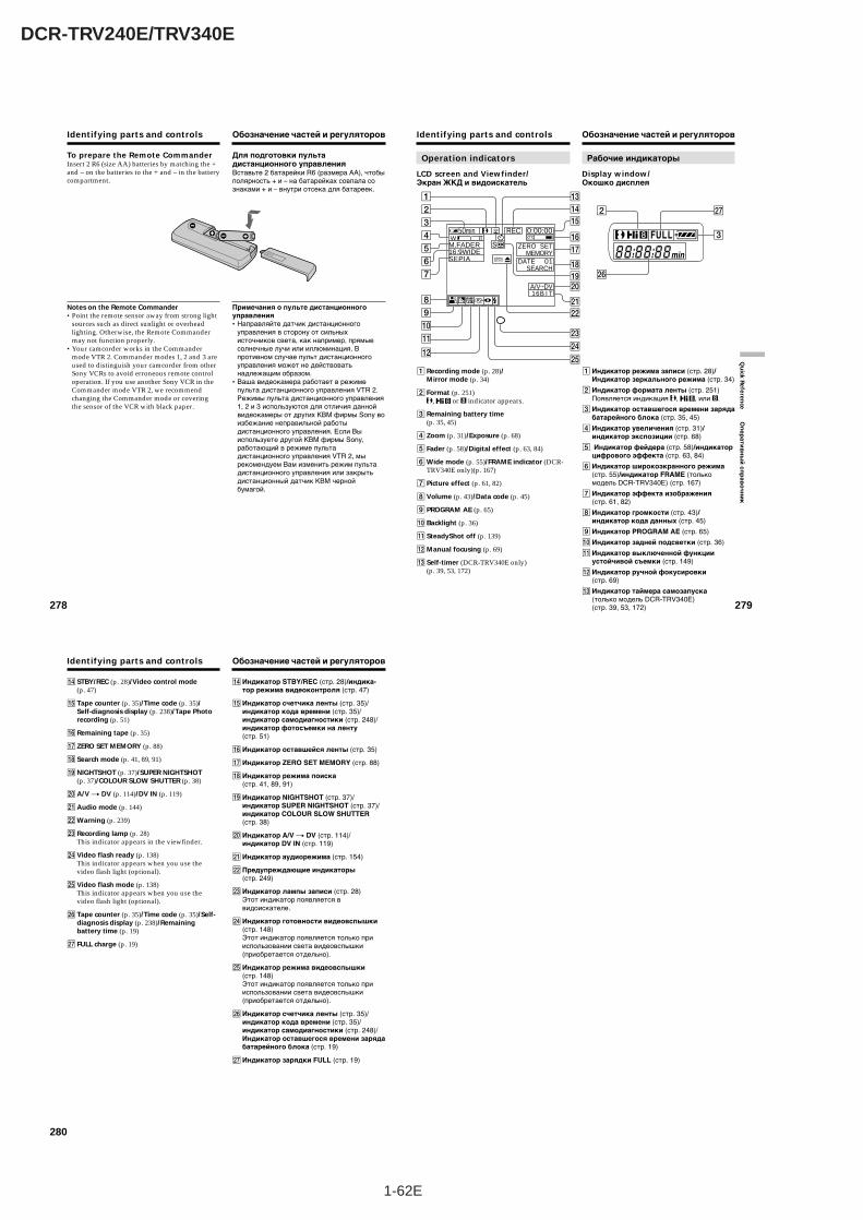
1-62E
DCR-TRV240E/TRV340E
278
To prepare the Remote CommanderInsert 2 R6 (size AA) batteries by matching the +and – on the batteries to the + and – in the batterycompartment.
Notes on the Remote Commander•Point the remote sensor away from strong light
sources such as direct sunlight or overheadlighting. Otherwise, the Remote Commandermay not function properly.
•Your camcorder works in the Commandermode VTR 2. Commander modes 1, 2 and 3 areused to distinguish your camcorder from otherSony VCRs to avoid erroneous remote controloperation. If you use another Sony VCR in theCommander mode VTR 2, we recommendchanging the Commander mode or coveringthe sensor of the VCR with black paper.
Identifying parts and controls Обозначение частей и регуляторов
Для подготовки пультадистанционного управленияВставьте 2 батарейки R6 (размера АА), чтобыполярность + и – на батарейках совпала сознаками + и – внутри отсека для батареек.
Примечания о пульте дистанционногоуправления•Направляйте датчик дистанционного
управления в сторону от сильныхисточников света, как например, прямыесолнечные лучи или иллюминация. Впротивном случае пульт дистанционногоуправления может не действоватьнадлежащим образом.
•Ваша видеокамера работает в режимепульта дистанционного управления VTR 2.Режимы пульта дистанционного управления1, 2 и 3 используются для отличия даннойвидеокамеры от других КВМ фирмы Sony воизбежание неправильной работыдистанционного управления. Если Выиспользуете другой КВМ фирмы Sony,работающий в режиме пультадистанционного управления VTR 2, мырекомендуем Вам изменить режим пультадистанционного управления или закрытьдистанционный датчик КВМ чернойбумагой.
279
Qu
ick Referen
ce Оп
ерати
вн
ый
спр
аво
чни
к
Identifying parts and controls
Operation indicators
LCD screen and Viewfinder/Экран ЖКД и видоискатель
Рабочие индикаторы
Display window/Окошко дисплея
50min REC 0:00:00
M.FADER16:9WIDESEPIA
16B I T
TW
DATE 01SEARCH
ZERO SETMEMORY
A/V DV
SP
2
4
5
6
7
8
9
0
qa
qs
3
1 qd
qf
qh
ql
wa
w;
ws
wf
wd
wg
qk
qj
qg
wh
2 wj
3
1 Recording mode (p. 28)/Mirror mode (p. 34)
2 Format (p. 251), or indicator appears.
3 Remaining battery time(p. 35, 45)
4 Zoom (p. 31)/Exposure (p. 68)
5 Fader (p. 58)/Digital effect (p. 63, 84)
6Wide mode (p. 55)/FRAME indicator (DCR-TRV340E only)(p. 167)
7 Picture effect (p. 61, 82)
8 Volume (p. 43)/Data code (p. 45)
9 PROGRAM AE (p. 65)
0 Backlight (p. 36)
qa SteadyShot off (p. 139)
qsManual focusing (p. 69)
qd Self-timer (DCR-TRV340E only)(p. 39, 53, 172)
Обозначение частей и регуляторов
1Индикатор режима записи (стр. 28)/Индикатор зеркального режима (стр. 34)
2Индикатор формата ленты (стр. 251)Появляется индикация , , или .
3Индикатор оставшегося времени зарядабатарейного блока (стр. 35, 45)
4Индикатор увеличения (стр. 31)/индикатор экспозиции (стр. 68)
5 Индикатор фейдера (стр. 58)/индикаторцифрового эффекта (стр. 63, 84)
6Индикатор широкоэкранного режима(стр. 55)/индикатор FRAME (толькомодель DCR-TRV340E) (стр. 167)
7Индикатор эффекта изображения(стр. 61, 82)
8Индикатор громкости (стр. 43)/индикатор кода данных (стр. 45)
9Индикатор PROGRAM AE (стр. 65)
0Индикатор задней подсветки (стр. 36)
qaИндикатор выключенной функцииустойчивой съемки (стр. 149)
qsИндикатор ручной фокусировки(стр. 69)
qdИндикатор таймера самозапуска(только модель DCR-TRV340E)(стр. 39, 53, 172)
280
Identifying parts and controls
qf STBY/REC (p. 28)/Video control mode(p. 47)
qg Tape counter (p. 35)/Time code (p. 35)/Self-diagnosis display (p. 238)/Tape Photorecording (p. 51)
qh Remaining tape (p. 35)
qj ZERO SET MEMORY (p. 88)
qk Search mode (p. 41, 89, 91)
qlNIGHTSHOT (p. 37)/SUPER NIGHTSHOT(p. 37)/COLOUR SLOW SHUTTER (p. 38)
w;A/V t DV (p. 114)/DV IN (p. 119)
waAudio mode (p. 144)
wsWarning (p. 239)
wd Recording lamp (p. 28)This indicator appears in the viewfinder.
wf Video flash ready (p. 138)This indicator appears when you use thevideo flash light (optional).
wg Video flash mode (p. 138)This indicator appears when you use thevideo flash light (optional).
wh Tape counter (p. 35)/Time code (p. 35)/Self-diagnosis display (p. 238)/Remainingbattery time (p. 19)
wj FULL charge (p. 19)
Обозначение частей и регуляторов
qfИндикатор STBY/REC (стр. 28)/индика-тор режима видеоконтроля (стр. 47)
qgИндикатор счетчика ленты (стр. 35)/индикатор кода времени (стр. 35)/индикатор самодиагностики (стр. 248)/индикатор фотосъемки на ленту(стр. 51)
qhИндикатор оставшейся ленты (стр. 35)
qjИндикатор ZERO SET MEMORY (стр. 88)
qkИндикатор режима поиска(стр. 41, 89, 91)
qlИндикатор NIGHTSHOT (стр. 37)/индикатор SUPER NIGHTSHOT (стр. 37)/индикатор COLOUR SLOW SHUTTER(стр. 38)
w;Индикатор A/V t DV (стр. 114)/индикатор DV IN (стр. 119)
waИндикатор аудиорежима (стр. 154)
wsПредупреждающие индикаторы(стр. 249)
wdИндикатор лампы записи (стр. 28)Этот индикатор появляется ввидоискателе.
wfИндикатор готовности видеовспышки(стр. 148)Этот индикатор появляется только прииспользовании света видеовспышки(приобретается отдельно).
wgИндикатор режима видеовспышки(стр. 148)Этот индикатор появляется только прииспользовании света видеовспышки(приобретается отдельно).
whИндикатор счетчика ленты (стр. 35)/индикатор кода времени (стр. 35)/индикатор самодиагностики (стр. 248)/Индикатор оставшегося времени зарядабатарейного блока (стр. 19)
wjИндикатор зарядки FULL (стр. 19)
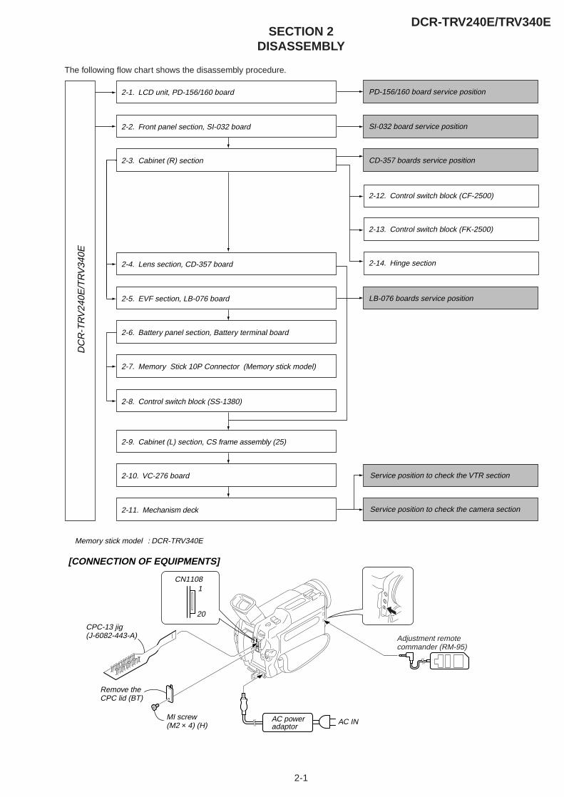
2-1
SECTION 2DISASSEMBLY
DCR-TRV240E/TRV340E
The following flow chart shows the disassembly procedure.D
CR
-TR
V24
0E/T
RV
340E
2-1. LCD unit, PD-156/160 board PD-156/160 board service position
2-2. Front panel section, SI-032 board SI-032 board service position
LB-076 boards service position
CD-357 boards service position2-3. Cabinet (R) section
2-4. Lens section, CD-357 board 2-14. Hinge section
2-12. Control switch block (CF-2500)
2-13. Control switch block (FK-2500)
2-5. EVF section, LB-076 board
2-6. Battery panel section, Battery terminal board
2-7. Memory Stick 10P Connector (Memory stick model)
2-8. Control switch block (SS-1380)
2-9. Cabinet (L) section, CS frame assembly (25)
2-10. VC-276 board
2-11. Mechanism deck
Memory stick model : DCR-TRV340E
Service position to check the VTR section
Service position to check the camera section
[CONNECTION OF EQUIPMENTS]
AC INAC power adaptor
MI screw (M2 × 4) (H)
Remove the CPC lid (BT)
CN1108
20
1
Adjustment remotecommander (RM-95)
CPC-13 jig(J-6082-443-A)
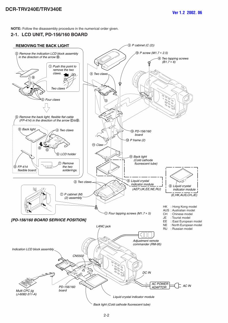
2-2
DCR-TRV240E/TRV340E
NOTE: Follow the disassembly procedure in the numerical order given.
2-1. LCD UNIT, PD-156/160 BOARD
PD-Board
PD-156/160
Board
[PD-156/160 BOARD SERVICE POSITION]
Back light (Cold cathode fluorescent tube)
Adjustment remotecommander (RM-95)
PD-156/160boardMulti CPC jig
(J-6082-311-A)Liquid crystal indicator module
Indication LCD block assembly
LANC jack
CN5502
DC IN
AC POWERADAPTOR AC IN
2 Two claws
4 Two claws
qa Claw
5
1 Four tapping screws (M1.7 × 5)
qs P frame (2)
9 Back light (Cold cathode fluorescent tube)
6 Two tapping screws (B1.7 × 6)
q; P screw (M1.7 × 2.5)
3 P cabinet (C (2))
7 P cabinet (M) (2) assembly
qd PD-156/160 board
8 Liquid crystal indicator module
REMOVING THE BACK LIGHT
4 Two claws
2 Four claws
Two claws
B
9 Back light
CD
7 Remove the two solderings.
6 LCD holder
3 Remove the indication LCD block assembly in the direction of the arrow B.
5 Remove the back light, flexible flat cable (FP-414) in the direction of the arrow CtoD.
1 Push this point to remove the two claws.
8 FP-414 flexible board
8 Liquid crystal indicator module(AEP,UK,EE,NE,RU)
(E,HK,AUS,CH,JE)
HK : Hong Kong modelAUS : Australian modelCH : Chinese modelJE : Tourist modelEE : East European modelNE : North European modelRU : Russian model
Ver 1.2 2002. 06
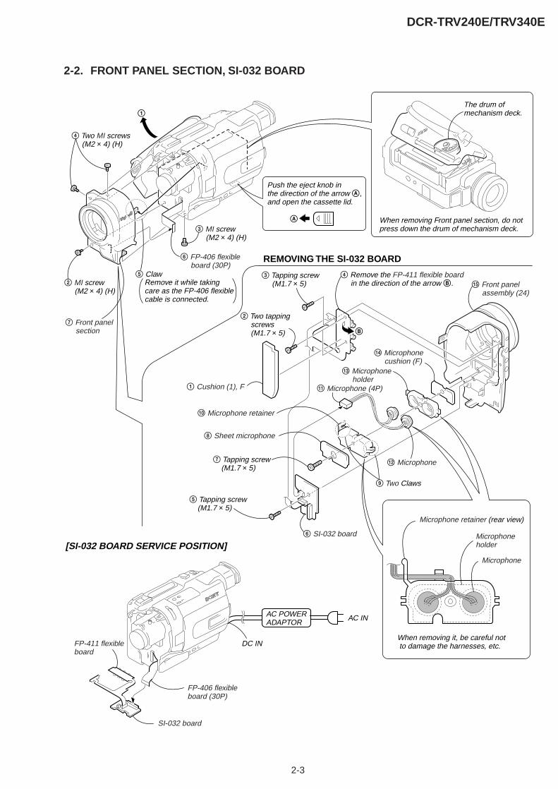
2-3
DCR-TRV240E/TRV340E
2-2. FRONT PANEL SECTION, SI-032 BOARD
B
1
FP-406 flexible board (30P)
6 SI-032 board
SI-032 board
qg Front panel assembly (24)
1 Cushion (1), F
8 Sheet microphone
[SI-032 BOARD SERVICE POSITION]
AC INAC POWERADAPTOR
Microphone
When removing it, be careful not to damage the harnesses, etc.
When removing Front panel section, do not press down the drum of mechanism deck.
The drum of mechanism deck.
Microphone retainer (rear view)
Microphone holder
q; Microphone retainer
qd Microphone holder
REMOVING THE SI-032 BOARD
2 MI screw (M2 × 4) (H)
3 Tapping screw (M1.7 × 5)
2 Two tapping screws (M1.7 × 5)
5 Tapping screw (M1.7 × 5)
7 Tapping screw (M1.7 × 5)
4 Remove the FP-411 flexible board in the direction of the arrow B.
DC IN
qs Microphone
qa Microphone (4P)
qf Microphone cushion (F)
3 MI screw (M2 × 4) (H)
6 FP-406 flexible board (30P)
4 Two MI screws (M2 × 4) (H)
Push the eject knob in the direction of the arrow A, and open the cassette lid.
A
7 Front panel section
5 Claw
9 Two Claws
FP-411 flexibleboard
Remove it while taking care as the FP-406 flexible cable is connected.

2-4
DCR-TRV240E/TRV340E
2-3. CABINET (R) SECTION
2 Three claws
5 Claw
7 Claw
qh Cabinet (R) block section
qg Harness (PD-117) (20P)
3 Cabinet (upper)
qd Night-Shot switch of Lens device (LSV-700A)
1 MI screw (M2 × 4) (H)
qf Control switch block (CF-2500) (22P)
q; Three MI screws (M2 × 4) (H)
qa Three MI screws (M2 × 4) (H)
4 MI screw (M2 × 4) (H)
9 MI screw (M2 × 4) (H)
6 Jack cover retainer8 Jack cover
qs Two MI screws (M2 × 4) (H)
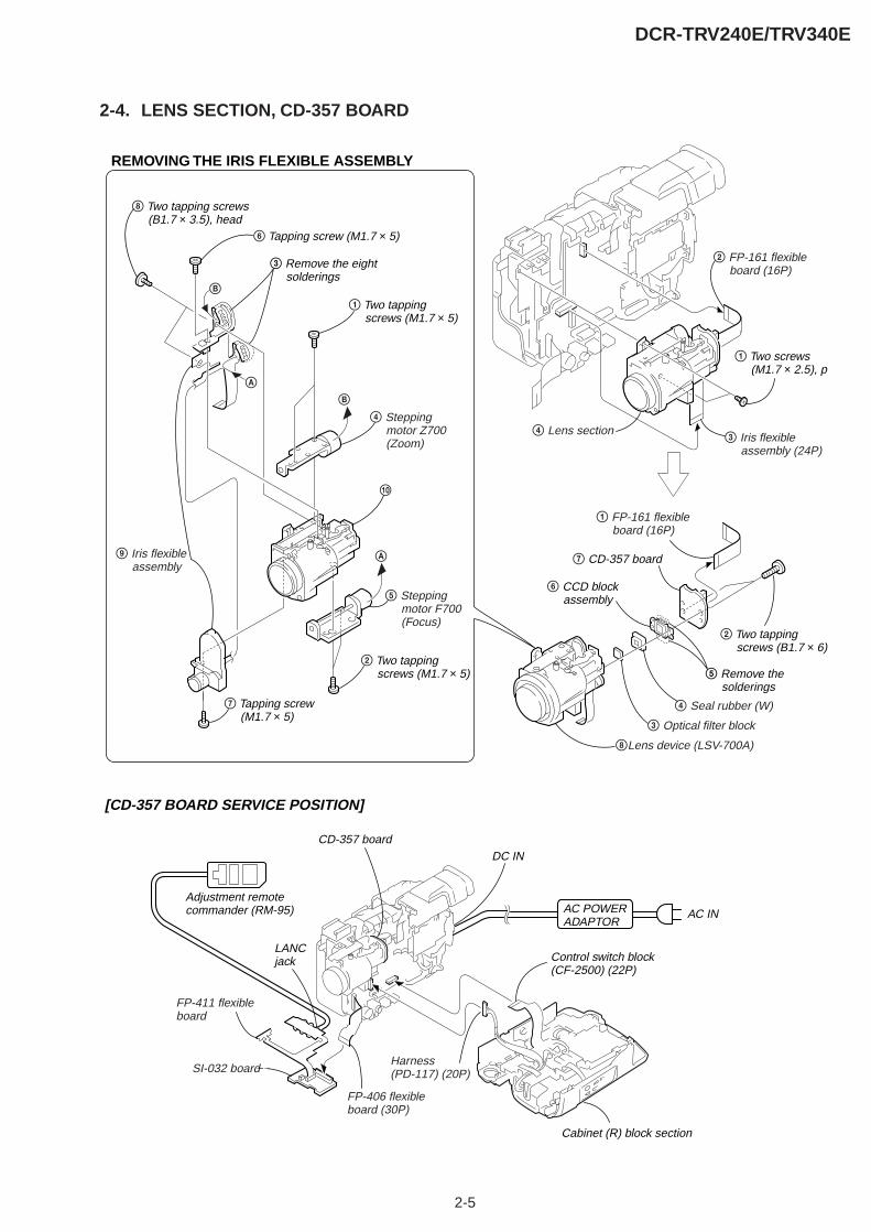
2-5
DCR-TRV240E/TRV340E
2-4. LENS SECTION, CD-357 BOARD
1 Two screws (M1.7 × 2.5), p
2 FP-161 flexible board (16P)
3 Iris flexible assembly (24P)
4 Lens section
6 Tapping screw (M1.7 × 5)
2 Two tapping screws (B1.7 × 6)
1 FP-161 flexible board (16P)
q;
4 Seal rubber (W)
7 CD-357 board
CD-357 board
3 Optical filter block
6 CCD block assembly
5 Remove the solderings
3 Remove the eight solderings
7 Tapping screw (M1.7 × 5)
1 Two tapping screws (M1.7 × 5)
8 Two tapping screws (B1.7 × 3.5), head
9 Iris flexible assembly
2 Two tapping screws (M1.7 × 5)
4 Stepping motor Z700 (Zoom)
5 Stepping motor F700 (Focus)
A
A
B
B
REMOVING THE IRIS FLEXIBLE ASSEMBLY
8Lens device (LSV-700A)
[CD-357 BOARD SERVICE POSITION]
AC INAC POWERADAPTOR
DC IN
Adjustment remotecommander (RM-95)
SI-032 board
Cabinet (R) block section
Control switch block (CF-2500) (22P)
Harness (PD-117) (20P)
LANC jack
FP-406 flexibleboard (30P)
FP-411 flexibleboard
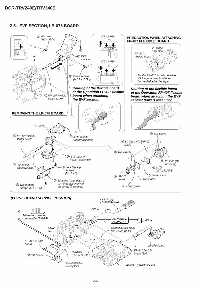
2-6
DCR-TRV240E/TRV340E
2-5. EVF SECTION, LB-076 BOARD
5 EVF section
VF hinge assembly
REMOVING THE LB-076 BOARD
PRECAUTION WHEN ATTACHING FP-407 FLEXIBLE BOARD
[LB-076 BOARD SERVICE POSITION]
FP-407 flexible board
6 EVF cabinet (upper) assembly
8 EVF cabinet (lower) assembly
9 FP-407 flexible board (20P)
1 FP-407 flexible board (20P)
FP-407 flexible board (20P)
5 Claw
2 Slide the lower plate of VF hinge assembly in the arrow A strongly.
1 Pull of the adhesive side. A
7
A
A
Fix the FP-407 flexible board to VF hinge assembly with the both-sided adhesive tape.
3 Two tapping screws (M1.7 × 5)
4 Four tapping screws (M1.7 × 5)
1 Two claws
4
2 Two claws
9 VF lens (B) assembly
6 Illuminator
4 LCD (LCX032AP-5) (16P)
8 LCD (LCX032AP-5)
7 Prism sheet
3 Lamp guide
5 LB-076 board
LB-076 board
Routing of the flexible boardof the Operation FP-407 flexibleboard when attaching the EVFcabinet (lower) assembly.
Routing of the flexible boardof the Operation FP-407 flexibleboard when attaching the EVF section.
AC INAC POWERADAPTOR
DC IN
CPC-13 jig(J-6082-443-A)
Adjustment remotecommander (RM-95)
SI-032 board
2 MI screw (M2 × 4) (H)
3 Three screws (M1.7 × 2.5), p
(TRV340E)
Cabinet (R) block section
Control switch block (CF-2500) (22P)
Harness (PD-117) (20P)
(TRV240E)
FP-406 flexibleboard (30P)
LANC jack
FP-411 flexibleboard

2-7
DCR-TRV240E/TRV340E
2-6. BATTERY PANEL SECTION, BATTERY TERMINAL BOARD
2-7. MEMORY STICK 10P CONNECTOR (MEMORY STICK MODEL) (TRV340E)
8 Memory stick 10p connector7 MS holder
4 MS section
2 Two screws (M1.7 × 2.5), p
1 Screw (M1.7 × 2.5), p
3
6 Two screws (M1.7 × 2.5), p
5 FP-409 flexible board (10P)
6 Two MI screws (M2 × 4) (H)
2 MI screw (M2 × 4) (H)
5 MI screw (M2 × 4) (H)
9 Battery panel section
2 Ferrite bead
1 Tape (A)
8
A
3
4
(Memory stick model) (TRV340E)
7 Tapping screw (M1.7 × 5)
3 FP-409 flexible board (10P)
5Strap sheet metal (lower)
6 Battery terminal board
4 Battery terminal board (6P)
1 Jack lid (2500)
REMOVING THE BATTERY TERMINAL BOARD
A
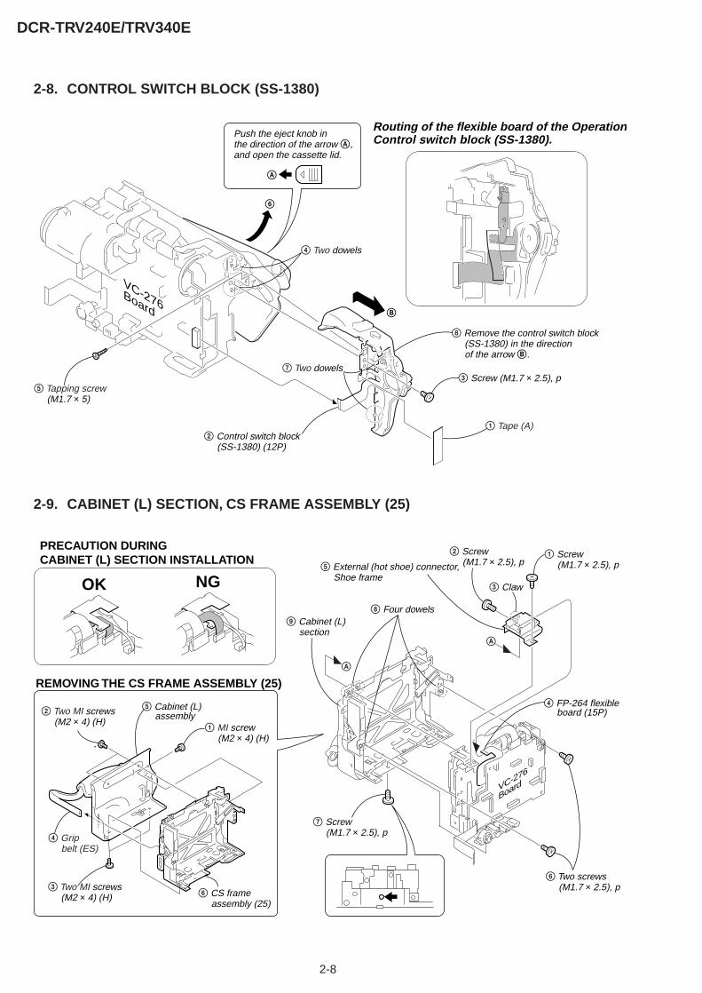
2-8
DCR-TRV240E/TRV340E
2-8. CONTROL SWITCH BLOCK (SS-1380)
2-9. CABINET (L) SECTION, CS FRAME ASSEMBLY (25)
B
6
8 Remove the control switch block (SS-1380) in the direction of the arrow B.
3 Screw (M1.7 × 2.5), p
4 Two dowels
7 Two dowels
1 Tape (A)
5 Tapping screw (M1.7 × 5)
VC-276Board
2 Control switch block (SS-1380) (12P)
Push the eject knob in the direction of the arrow A, and open the cassette lid.
A
Routing of the flexible board of the OperationControl switch block (SS-1380).
VC-276
Board
8 Four dowels
3 Claw
9 Cabinet (L) section
5 External (hot shoe) connector, Shoe frame
6 Two screws (M1.7 × 2.5), p
2 Screw (M1.7 × 2.5), p
7 Screw (M1.7 × 2.5), p
1 Screw (M1.7 × 2.5), p
5 Cabinet (L) assembly
1 MI screw (M2 × 4) (H)
3 Two MI screws (M2 × 4) (H)
2 Two MI screws (M2 × 4) (H)
4 Grip belt (ES)
REMOVING THE CS FRAME ASSEMBLY (25)
6 CS frame assembly (25)
A
A
4 FP-264 flexible board (15P)
PRECAUTION DURING CABINET (L) SECTION INSTALLATION
OK NG

2-9
DCR-TRV240E/TRV340E
2-10.VC-276 BOARD
VC-276
Board
DB
AC
ED
E
CB
A
7 VC sheet
8 VC-276 board
2 Screw (M1.7 × 2.5), p
4 Two screws (M1.7 × 2.5), p
5
3 FP-410 flexible board
6 FP-264 flexible board (20P)
1 MI screw (M2 × 4) (H)
2-11.MECHANISM DECK
5 MD frame
4
1 Turn over VC-276 board in the direction of the arrow.
6 Mechanism deck
VC-276
Board
2 Three screws (M1.7 × 2.5), p
3 Three dowels

2-10
DCR-TRV240E/TRV340E
Adjustment remotecommander (RM-95)
AC IN
DC IN
AC POWERADAPTOR
FP-406 flexible board (30P)
Control switch block (SS-1380) (12P)
Mechanism deck
CPC-13 jig(J-6082-443-A)
FP-410 flexible board
FP-411flexible board
SI-032 board
Battery panel section
Battery terminal board (6P)
VC-276board
LANC jack
VC-276
Board
A
Cabinet (R) block section
(Raise the hook in the direction of the arrow A.)
How to raise the cassette compartment manually
Control switch block (CF-2500) (22P)
Harness (PD-117) (20P)
CN1109
CN1108
12
2
To eject the cassette, short the circuit between pin qs and pin 2 (GND) ofCN1109 on VC-276 board for 1 second.
To check the VTR section, set the VTR to the “Forced VTR power ON” mode. Operate the VTR functions using the adjustment remote commander (with the HOLD switch set in the OFF position).
[SERVICE POSITION TO CHECK THE VTR SECTION]
Setting the “Forced VTR Power ON” mode
Cnnection to Check the VTR Section
1) Select page: 0, address: 01, and set data: 01.2) Select page: 0, address: 10, and set data: 00.3) Select page: D, address: 10, set data: 02 and
press the PAUSE button of the adjustment remotecommander.
Exiting the “Forced VTR Power ON” mode
1) Select page: 0, address: 01, and set data: 01.2) Select page: 0, address: 10, and set data: 00.3) Select page: D, address: 10, set data: 00, and press the PAUSE button of the adjustment remote commander.4) Select page: 0, address: 01, and set data: 00.
Note : If the machine malfunctions (the operating mode changes by itself), connect the Cabinet (R) section.
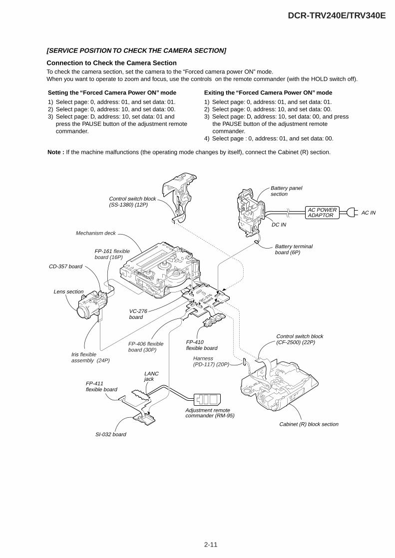
2-11
DCR-TRV240E/TRV340E
Adjustment remotecommander (RM-95)
AC IN
DC IN
AC POWERADAPTOR
FP-406 flexible board (30P)
Control switch block (SS-1380) (12P)
Mechanism deck
FP-410 flexible board
FP-161 flexible board (16P)
Iris flexible assembly (24P)
Battery panel section
Battery terminal board (6P)
VC-276board
Lens section
LANC jack
SI-032 board
VC-276
Board
CD-357 board
Cabinet (R) block section
Control switch block (CF-2500) (22P)
Harness (PD-117) (20P)
[SERVICE POSITION TO CHECK THE CAMERA SECTION]
Note : If the machine malfunctions (the operating mode changes by itself), connect the Cabinet (R) section.
Connection to Check the Camera SectionTo check the camera section, set the camera to the “Forced camera power ON” mode. When you want to operate to zoom and focus, use the controls on the remote commander (with the HOLD switch off).
Setting the “Forced Camera Power ON” mode
1) Select page: 0, address: 01, and set data: 01.2) Select page: 0, address: 10, and set data: 00.3) Select page: D, address: 10, set data: 01 and
press the PAUSE button of the adjustment remotecommander.
Exiting the “Forced Camera Power ON” mode
1) Select page: 0, address: 01, and set data: 01.2) Select page: 0, address: 10, and set data: 00.3) Select page: D, address: 10, set data: 00, and press the PAUSE button of the adjustment remote commander.4) Select page : 0, address: 01, and set data: 00.
FP-411flexible board
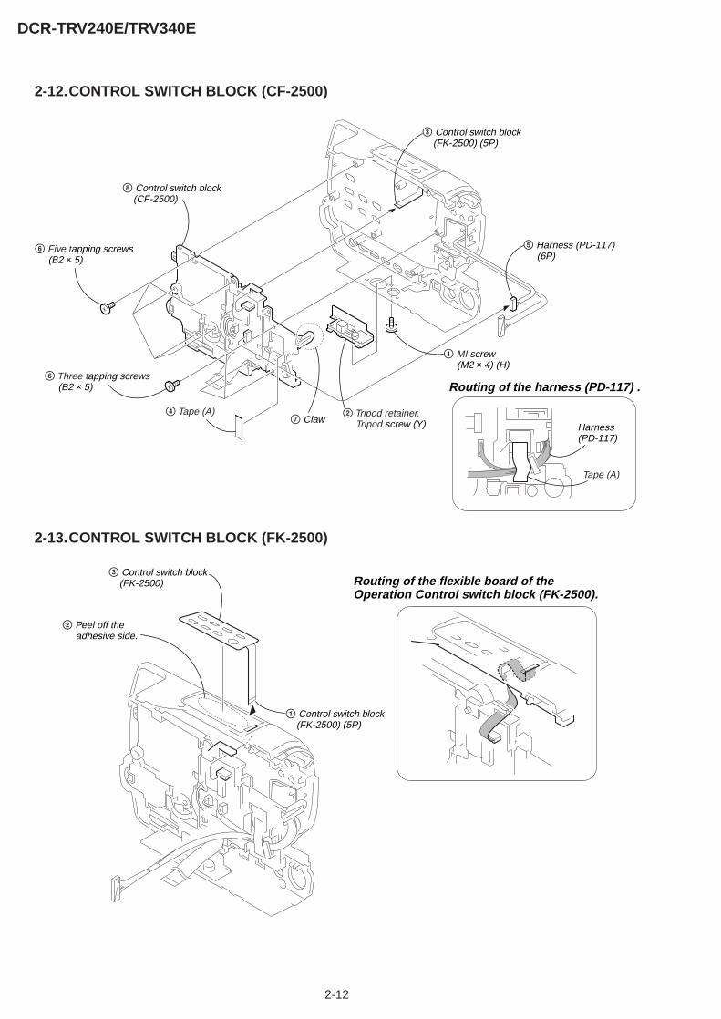
2-12
DCR-TRV240E/TRV340E
2-12.CONTROL SWITCH BLOCK (CF-2500)
6 Five tapping screws (B2 × 5)
6 Three tapping screws (B2 × 5)
4 Tape (A)
Tape (A)
8 Control switch block (CF-2500)
3 Control switch block (FK-2500) (5P)
5 Harness (PD-117) (6P)
Harness (PD-117)
1 MI screw (M2 × 4) (H)
2 Tripod retainer, Tripod screw (Y) 7 Claw
Routing of the harness (PD-117) .
2-13.CONTROL SWITCH BLOCK (FK-2500)
3 Control switch block (FK-2500)
1 Control switch block (FK-2500) (5P)
2 Peel off the adhesive side.
Routing of the flexible board of the Operation Control switch block (FK-2500).
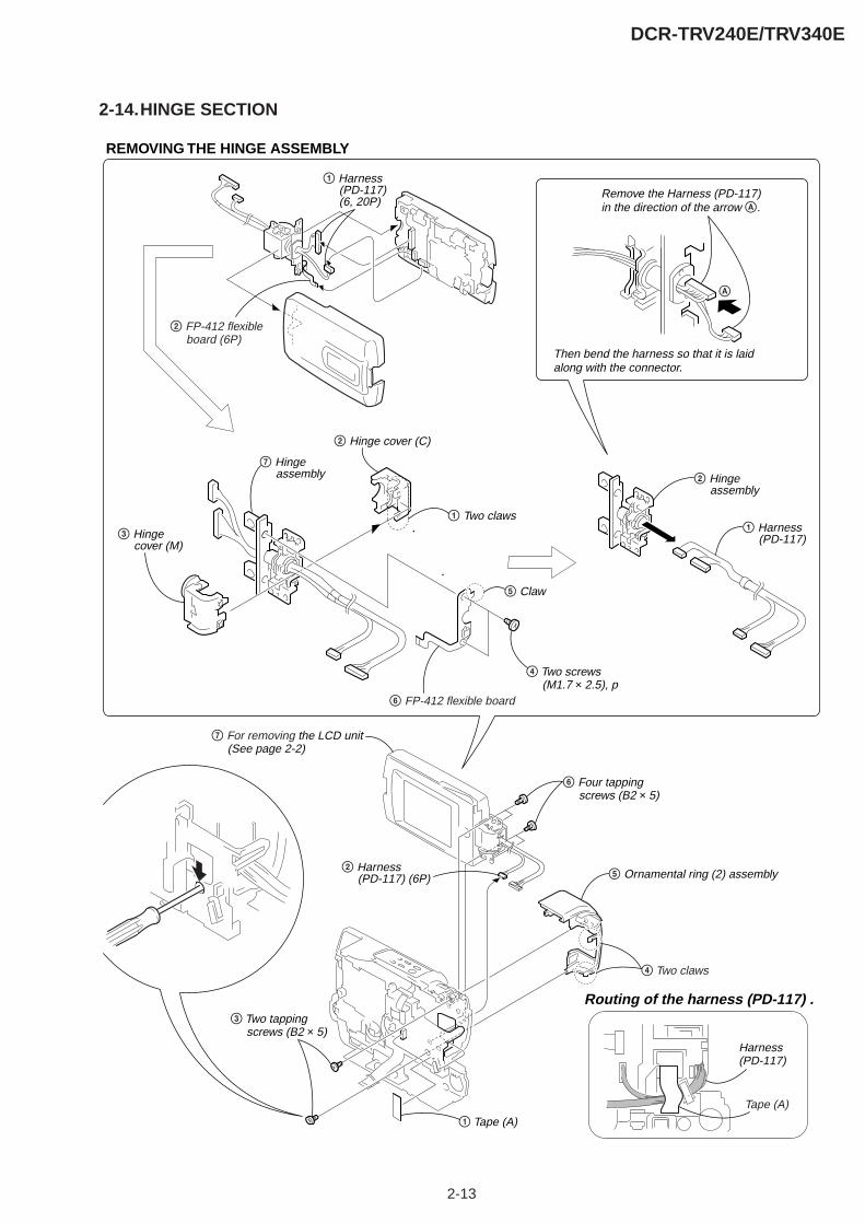
2-13
DCR-TRV240E/TRV340E
2-14.HINGE SECTION
6 Four tapping screws (B2 × 5)
3 Two tapping screws (B2 × 5)
1 Tape (A)
5 Ornamental ring (2) assembly
4 Two claws
2 Harness (PD-117) (6P)
REMOVING THE HINGE ASSEMBLY
2 FP-412 flexible board (6P)
1 Harness (PD-117) (6, 20P)
2 Hinge assembly
1 Harness (PD-117)
6 FP-412 flexible board
4 Two screws (M1.7 × 2.5), p
2 Hinge cover (C)
3 Hinge cover (M)
1 Two claws
5 Claw
A
Remove the Harness (PD-117) in the direction of the arrow A.
Then bend the harness so that it is laid along with the connector.
7 Hinge assembly
7 For removing the LCD unit (See page 2-2)
Tape (A)
Harness (PD-117)
Routing of the harness (PD-117) .

2-14
DCR-TRV240E/TRV340E
2-15.CIRCUIT BOARDS LOCATION
CD-357
CCD IMAGEREVF BACK LIGHTCHA, DISPLAY DRIVE, BACK LIGHT/LCD DRIVE, TGSTEADY SHOT, LASER LINKCAMERA, VIDEO, DV INTERFACE, CAMERA/MECHA/HI CONTROL, AUDIO, D/D CONVERTER
SI-032
LB-076
VC-276
CD-357LB-076PD-156/160SI-032
VC-276
NAME FUNCTION
PD-156 (AEP,UK,EE,NE,RU)/PD-160 (E,HK,AUS,CH,JE)
HK : Hong Kong modelAUS : Australian modelCH : Chinese modelJE : Tourist modelEE : East European modelNE : North European modelRU : Russian model

2-15E
DCR-TRV240E/TRV340E
2-16.FLEXIBLE BOARDS LOCATIONThe flexible boards contained in the mechanism deck are not shown.
FP-411
FP-414
FP-412
FP-407
FP-409(MEMORY STICK MODEL)(TRV340E)
FP-410
FP-161
FP-406
CONTROL SWITCH BLOCK (SS-1380)
CONTROL SWITCH BLOCK (CF-2500)
CONTROL SWITCH BLOCK (FK-2500)
IRIS FLEXIBLE ASSEMBLY
FP-264
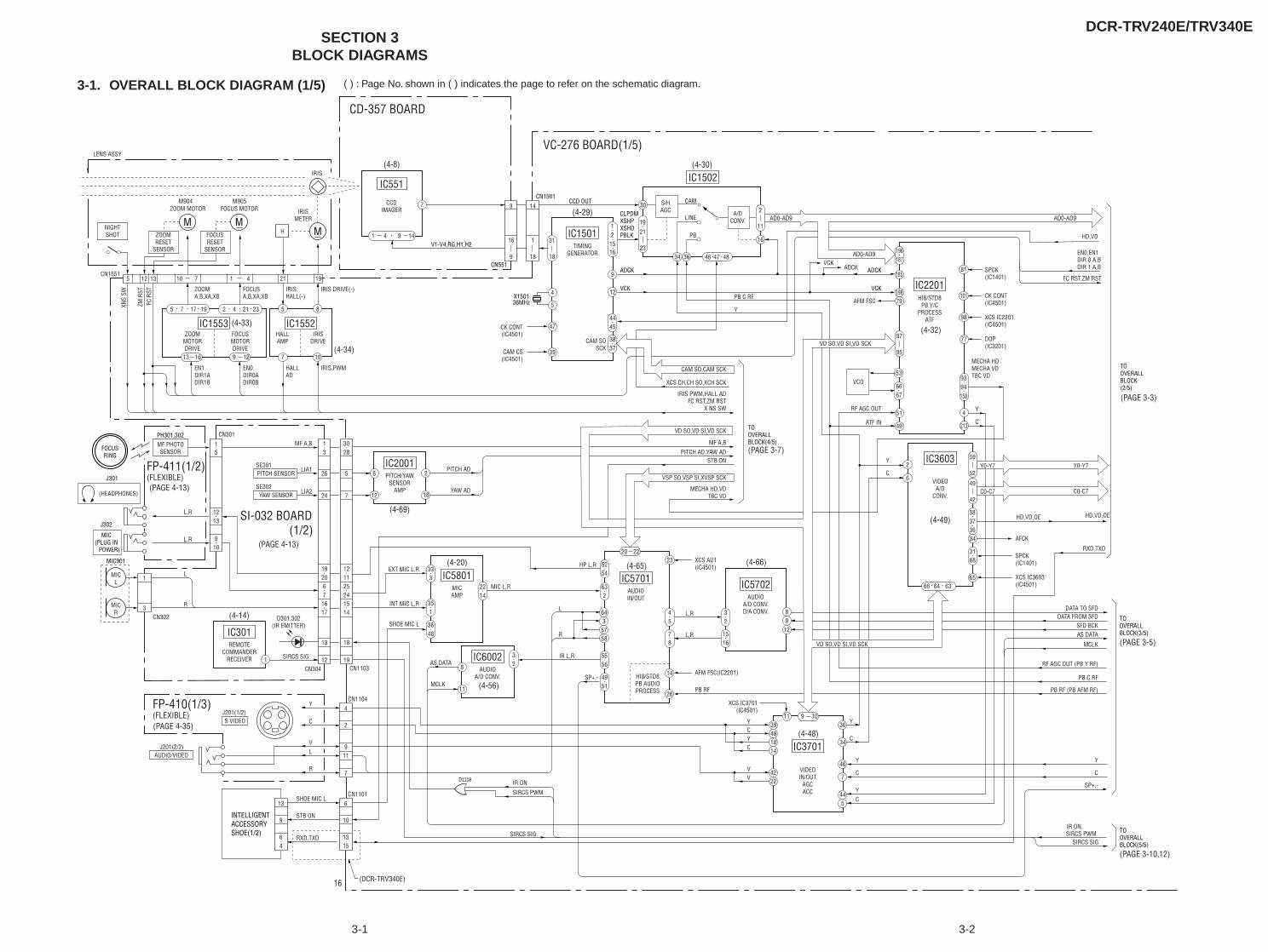
DCR-TRV240E/TRV340E
3-1 3-2
SECTION 3BLOCK DIAGRAMS
3-1. OVERALL BLOCK DIAGRAM (1/5) ( ) : Page No. shown in ( ) indicates the page to refer on the schematic diagram.
MZOOM MOTOR
M904 M905
XNS
SW
ZM R
ST
ZOOMRESET
SENSOR
NIGHTSHOT
MFOCUS MOTOR
M
IRISMETER
FOCUSRESET
SENSOR
7 10
5 8
9 1213 16
5 7 17 19 2 4
(4-33)
(4-34)
(4-8)
(4-29)
(4-30)
(4-32)
(4-49)
(4-66)(4-65)(4-20)
(4-56)
(4-14)
(4-69)
(4-48)
(PAGE 3-5)
(PAGE 3-10,12)
(PAGE 3-7)
(PAGE 3-3)
(PAGE 4-35)
(PAGE 4-13)
(PAGE 4-13)
21 23
66 64 63
IC1553FOCUSMOTORDRIVE
IC1552IRIS
DRIVEZOOM
MOTORDRIVE
EN1DIR1ADIR1B
HALLAMP
7
1 4 9 14
IC551
CCDIMAGER
9
124
30 S/HAGC
34 36
16
5
39
12
1615
444547
3837
31
18
21
23
IC1501TIMING
GENERATOR
IC1502
46 4847
A/DCONV.
CAM
LINE
PB
VCO53
185
98
77
51
49
4
213
81
79198
9394158
6667
196187
101
97
95
IC2201HI8/STD8
PB Y/CPROCESS
ATF
2
6
34
65
383736
3168
49
42
IC3603
VIDEOA/D
CONV.
643
57
8912
58
23
14
26
5254
45
78
32
1516
632
5556
4951
20 22
IC5701AUDIOIN/OUT
HI8/STD8PB AUDIOPROCESS
IC5702AUDIO
A/D CONV.D/A CONV.
36
34
46
7
445
11
18
3948
4222
14
9 10
IC3701
VIDEOIN/OUT
AGCACC
IC5801MICAMP
8
12
2
18
IC2001PITCH/YAW
SENSORAMP
2214
32
333
35INT MIC L,R
SHOE MIC L
1
3648
1
IC301REMOTE
COMMANDERRECEIVER
1
12
26
SE302YAW SENSOR
3
24
1920671617
13
30
19
5
28
7
121125241514
18
1
10
D301,302(IR EMITTER)
MICL
MICR
MIC901
1213
5
9
1
CN302
L
L,R
L,R
R3
CN304
SIRCS SIG
EXT MIC L,R
PITCH AD
YAW AD
MIC L,R
HP L,R
MF A,B
IR L,R
L
R
YCYC
VV
IR ON
SIRCS PWM
XCS IC3701(IC4501)
AFM FSC(IC2201)
XCS AU1(IC4501)
XCS IC3603(IC4501)
SPCK(IC1401)
CK CONT(IC4501)
SPCK(IC1401)
XCS IC2201(IC4501)
DOP(IC3201)
AFCK
HD,VD,OE HD,VD,OE
RXD,TXD
Y
C
AFM FSC
EN0,EN1DIR 0 A,BDIR 1 A,B
FC RST,ZM RST
HD,VD
PB RF
C C
Y Y
SFD BCKAS DATA
MCLK
DATA FROM SFDDATA TO SFD
SE301
CN301MF A,B
LIA1
LIA2
PITCH SENSOR
J201(1/2)S VIDEO
J201(2/2)AUDIO/VIDEO
MF PHOTOSENSOR
CK CONT(IC4501)
CAM CS(IC4501)
8
11
IC6002AUDIO
A/D CONV.
Y
SHOE MIC L
C
STB ON
RXD,TXD
VL
R
SP+,-
SP+,-
L,R
MECHA HD,VDTBC VD
L,R
ADCK
MECHA HDMECHA VDTBC VD
MIC(PLUG IN
POWER)
J302
J301
PH301,302
FOCUSRING
FP-411(1/2)(FLEXIBLE)
FP-410(1/3)(FLEXIBLE)
SI-032 BOARD (1/2)
VC-276 BOARD(1/5)
CD-357 BOARD
CN1103
CN11044
2
911
7
CN11016
10
1315
16
13
9
64
INTELLIGENTACCESSORYSHOE(1/2)
IRIS PWM,HALL ADFC RST,ZM RST
X NS SW
STB ON
Y
PB C RF
PITCH AD,YAW AD
SIRCS SIG
YC
IR ON, SIRCS PWM
PB RF (PB AFM RF)
PB C RF
RF AGC OUT (PB Y RF)
SIRCS SIG
C
Y
RF AGC OUT
ATF IN
Y
C
5 12 13 21
H
19
IRIS
10 7 1 4
FC R
ST
EN0DIR0ADIR0B
HALLAD
IRIS PWM
ZOOMA,B,XA,XB
FOCUSA,B,XA,XB
IRISHALL(-)
IRIS DRIVE(-)
CN1551
LENS ASSY
CN551
CN1501
CLPDMXSHPXSHD
ADCK
PBLK
CCD OUT
V1-V4,RG,H1,H2
36MHzX1501
14
1
18
3
16
9
VCK
ADCK
VCK
VCK
59
52
C0-C7 C0-C7
Y0-Y7 Y0-Y7
TOOVERALLBLOCK(2/5)
TOOVERALLBLOCK(5/5)
TOOVERALLBLOCK(3/5)
TOOVERALLBLOCK(4/5)
VD SO,VD SI,VD SCK
VD SO,VD SI,VD SCK
CAM SO,CAM SCK
CAM SOSCK
XCS CH,CH SO,XCH SCK
VD SO,VD SI,VD SCK
2
11AD0-AD9
(HEADPHONES)
(DCR-TRV340E)
AS DATA
MCLK
VD SO,VD SI,VD SCK
VSP SO,VSP SI,XVSP SCK
AD0-AD9
AD0-AD9
19
VD SO,VD SI,VD SCK
D1118
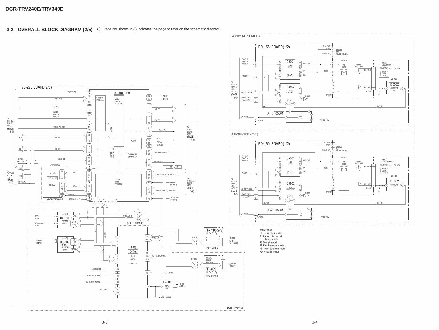
DCR-TRV240E/TRV340E
3-3 3-4
( ) : Page No. shown in ( ) indicates the page to refer on the schematic diagram.3-2. OVERALL BLOCK DIAGRAM (2/5)
Y0-Y7
IC4905XTALOSC
CO-C3
TOOVERALLBLOCK(3/5)
ADAI2
CN1104
CN1105
4
CN203
(USB)
COL0-COL3
D+D-
32
MS DIOMS BSMS SCLK
OSD HD,OSD VD
IC1401
IC4901(1/2)
TOOVERALLBLOCK(4/5)
2124
537
MEMORYSTICK
(FLEXIBLE)FP-410(2/3)
(FLEXIBLE)FP-409
X490148MHz
VC-276 BOARD(2/5)
(DCR-TRV340E)
2.5INCH
LCD UNIT
LCD901
PD-160 BOARD(1/2)
RGBDRIVE
PSIG
VR,VG,VB
VP
DAC
CN5502
HD OUTPSIG
VR,VG,VBFORADJUSTMENTS
CN5501
PANEL 2.8V
Q5601
(4-21)
IC5501
41
484746
27
CURRENT
INVERTER
BACKLIGHT
T5601Q5602/Q5604ND901
BACKLIGHT
BL HIGH
BL LOW
DET IN
CN5601
DRIVE
DET
IC56023 4
35
202224
4039
TIMINGGENERATOR
HD OUT
(4-21)
(4-20)
(4-20)
IC5502
IC5601
1
1
44
484
5 2
6
7
464542
2 58
15
24
84531
6
453
2
87
1213
BL REG10
3
CN5701
10
345
78
17
911
PANEL RPANEL GPANEL B
XCS LCD
VD SO,VD SCK
PANEL XHDPANEL XVD
BL CONT
TOOVERALLBLOCK(3/5)(VC-276)
19
22
(PAGE 3-5)
IC51021-9
16-2548
29-45
26CS FLASH(IC4901)
IC51012-12
39-49
19-3236DSCK(IC1401)
18CS SDARM(IC4901)
215
214
213
238
239
187
184
109
113
116
60
39
62
93
222
221
IC1402
SDRAM
115
74
99
25
97
91
117
118
119
6162
59
87
88
123
120
55
56
54
53
4847
46
34 27 22 119 236
135
170
153
144
137133
130
44
84
85
86
72
65
196
83
76
195
177
191
182
171
172
199
207
SFD BCK
ADAO2
HD,VD,OE
DSCK
SPCK
USB D+,D-
CAM SO,CAM SI,CAM SCK
VSP SO,VSP SI,XVPS SCK
CAM CS(IC4501)
XCS IC1401(IC4501)
DSCK(IC1401)
USB D+,D-
MS DIO, BS, SCLK
XTAL 48M LK
A1-A
23
D0-D
15
LXCS(IC1401)
CS SDRAM (IC5101)
CS FLASH (IC5102)
AD17-AD19
TOOVER ALLBLOCK(5/5)
2
1342
53
21
35
LXCS(IC4901)
(DCR-TRV240E)
(AEP/UK/EE/NE/RU MODEL)
(E/HK/AUS/CH/JE MODEL)
AbbreviationHK: Hong Kong modelAUS: Australian modelCH: Chinese modelJE: Tourist modelEE: East European modelNE: North European modelRU: Russian model
(DCR-TRV340E)
RXD, TXD
38MEMCK
D0-D15
A0-A11
AFCK(IC3603)
MPEGMOVIEPROCESS
CAMERAPROCESS
AUDIO
CHARACTERGENERATOR
DIGITALSTILLPROCESS
CAM
ERA
LINE
INHI
8/ST
D8 P
B
DIGITALSTILLCONTROL
VCK(IC1501)
Y0-Y7
C0-C7
AD0-AD9
Y0-Y7
C0-C7
Y0-Y7
C0-C3
HD,VD,OE
FC RST,ZM RST
RXD,TXDHD,VD,OE
DIR1A,BDIR0A,BEN0,EN1
HD,VD
TOOVERALLBLOCK(1/5)
TOOVERALLBLOCK(3/5)
FLASHMEMORY16Mbit
SDRAM16Mbit
HD,VD,OE
(PAGE 3-10)
(PAGE 3-7) (PAGE
3-5)
2.5INCH
LCD UNIT
LCD901
PD-156 BOARD(1/2)
RGBDRIVE
PSIG
VR,VG,VB
VP
DAC
CN5502
XHD OUTPSIG
VR,VG,VBFORADJUSTMENTS
CN5501
PANEL 2.8V
Q5601
(4-21)
IC5501
41
484746
27
CURRENT
INVERTER
BACKLIGHT
T5601Q5602/Q5604ND901
BACKLIGHT
BL HIGH
BL LOW
DET IN
CN5601
DRIVE
DET
IC56023 4
35
202224
4039
TIMINGGENERATOR
XHD OUT
(4-21)
(4-20)
(4-20)
IC5502
IC5601
1
1
44
484
5 2
6
7
464542
2 58
15
24
84531
6
453
2
87
1213
BL REG10
3
CN5701
10
345
78
17
911
PANEL RPANEL GPANEL B
XCS LCD
VD SO,VD SCK
PANEL XHDPANEL XVD
BL CONT
TOOVERALLBLOCK(3/5)(VC-276)
19
22(PAGE 3-5)
(PAGE 4-35)
(PAGE 4-64)
(4-39)
(4-40)
(4-35)
(4-35)
(4-38)
(PAGE 3-2)
(PAGE 3-5)
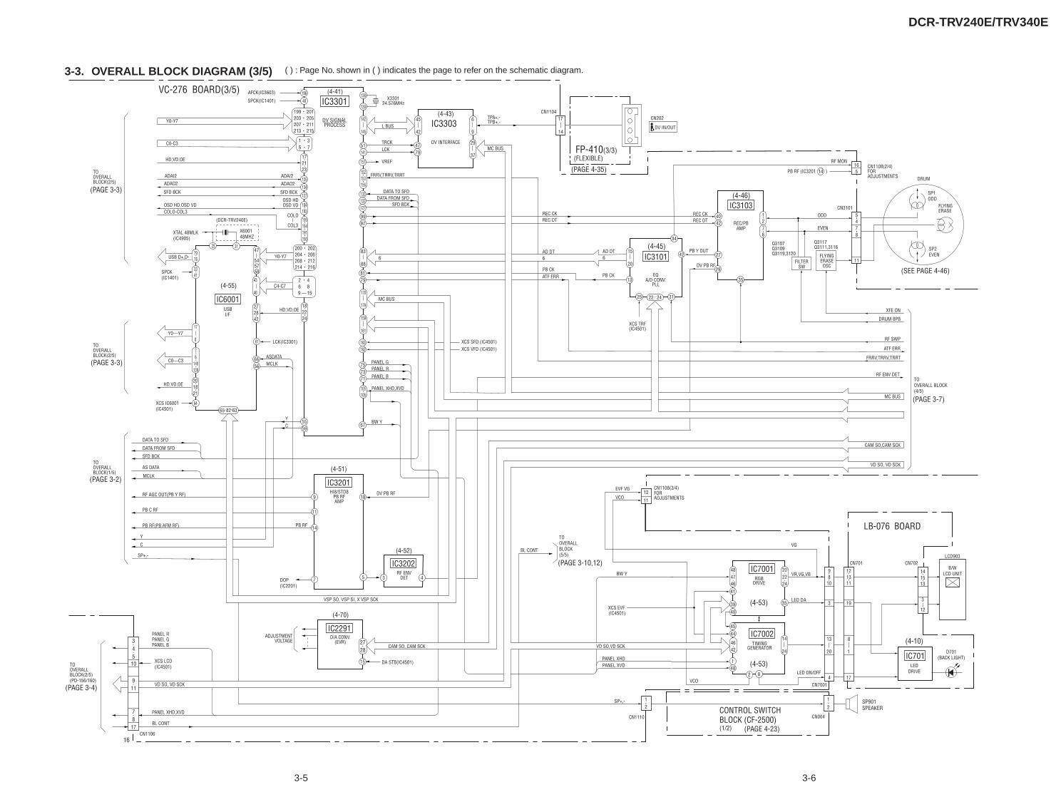
DCR-TRV240E/TRV340E
3-5 3-6
( ) : Page No. shown in ( ) indicates the page to refer on the schematic diagram.3-3. OVERALL BLOCK DIAGRAM (3/5)
(4-51)
(4-55)
PB RF
DV PB RF9
11
14
18
57
IC3201HI8/STD8
PB RFAMP
(4-52)
3 4
IC3202RF ENV
DET
(4-70)
15
IC2291D/A CONV.
(EVR)
DA STB(IC4501)
ADJUSTMENTVOLTAGE 27
28
Y
DV SIGNALPROCESS
(4-41)
DV INTERFACE
(4-43)
EQA/D CONV.
PLL
(4-45)PB Y OUT
REC/PBAMP
FILTERSW
FLYINGERASEOSC
Q3107Q3109Q3119,3120
Q3117Q3111,3116
FLYING
DRUM
ERASE
(4-46)
X330124.576MHz
L BUS
TRCKLCK
VREF
C
VC-276 BOARD(3/5)
IC6001
51141
133
127
163162
132
151
9997
4779
40
14
42
8179
75
67
134
73
5559
71
138
139
DV PB RF
XCS TRF(IC4501)
152153156
172123
105106
184183
22 24
195194191190
1276
47
545758
142
145
170
179
159
161
83
88
45
42
IC3101
IC3103
13
25 31
34
42 27
29
35
15
20
6
9
29
37
1 35 7
199 201203 205207 211213 215
200 202204 206208 212214 216
TOOVERALLBLOCK(5/5)
YC
USBI/F
135FRRV,TRRV,TRRT
DATA TO SFDDATA FROM SFD
XCS VFD (IC4501)XCS SFD (IC4501)
17CN1104
TPA+,-TPB+,-
14
5CN3101
RF MON
SP1ODD
ODD
EVEN 7
CN202
DV IN/OUT
(FLEXIBLE)FP-410(3/3)
PANEL G
PANEL XHD,XVD
PANEL B
PANEL R
PANEL XHD,XVD
PANEL RPANEL GPANEL B
SFD BCK
6 6AD DT
6AD DT
REC CK
PB CKPB CK
REC DT
ATF ERR
REC CKREC DT
XFE ON
DRUM 8PB
RF SWP
FRRV,TRRV,TRRT
ATF ERR
TOOVERALL BLOCK(4/5)
MC BUS
TOOVERALLBLOCK(1/5)
(PAGE 4-35)
(SEE PAGE 4-46)
(PAGE 3-7)
(PAGE 4-23)
(PAGE 3-10,12)
4
8
11
16 CN1108(2/4)FORADJUSTMENTS
PB RF (IC3201 ) 5
SP2EVEN
MC BUS
MC BUS
IC3301
IC3303
BW Y
SP+,-
182224
DATA TO SFD
DATA FROM SFD
SFD BCK
RF AGC OUT(PB Y RF)
CAM SO,CAM SCK
CAM SO, CAM SCK
PB C RF
PB RF(PB AFM RF)
17
10
45
911
78
3
BL CONT
CN110616
BL CONT
XCS LCD(IC4501)TO
OVERALLBLOCK(2/5)(PD-156/160)
LB-076 BOARD
XCS EVF (IC4501)
SP+,-
RGBDRIVE
VR,VG,VB
LED DA
CN1108(3/4)
VCO
EVF VGFORADJUSTMENTS
LCD903
B/WLCD UNIT
CN7001
CN004
(4-53)
IC7001
41
3940
484746
35
202224
TIMINGGENERATOR
PANEL XHD
VCO
BW Y
(4-53)
(4-10)IC7002
LEDDRIVE
D701(BACK LIGHT)IC701
1
4445
48
4642
2 8
14
24
11
12
3
141513
12
1
2
3
98
10
4
13
20
CN701 CN702
19
121311
17
8
1
CN1110
PANEL XVD
VD SO,VD SCK
SP901SPEAKER
VSP SO,VSP SI,XVSP SCK
VD SO, VD SCK
VSP SO, SI, SCK
(PAGE 3-2)
(PAGE 3-3)
(PAGE 3-3)
(PAGE 3-4)
RF ENV DET
VD SO, VD SCK
12
(1/2)
CONTROL SWITCHBLOCK (CF-2500)
VG
LED ON/OFF
VSP SO, VSP SI, X VSP SCK
65 82 6364
201821
76
140139
17
8
3341
7978
6656
43
46
272842
61
2 46 89 15
48
196
25 31
127
ASDATAMCLK
LCK(IC3301)
HD,VD,OE
C4-C7
Y0-Y7
XTAL 48MLK(IC4905)
X600148MHZ
(DCR-TRV240E)
USB D+,D-
Y0—Y7
C0—C3
HD,VD,OE
XCS IC6001(IC4501)
SPCK(IC1401)
COLO-COL3OSD HD,OSD VD
SFD BCK
ADAO2
ADAI2
HD,VD,OE
C0-C3
Y0-Y7
SPCK(IC1401)
AFCK(IC3603)
TOOVERALLBLOCK(2/5)
TOOVERALLBLOCK(2/5)
AS DATA
MCLK
ADAI2
ADAO2
SFD BCK
OSD VDOSD HD
COL3
COLO
DOP(IC2201)
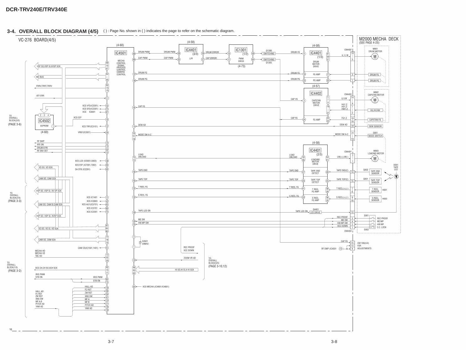
DCR-TRV240E/TRV340E
( ) : Page No. shown in ( ) indicates the page to refer on the schematic diagram.
3-7 3-8
3-4. OVERALL BLOCK DIAGRAM (4/5)
DRUM PWM DRUM PWM
CAP PWM CAP PWM
DRUM ERROR
CAP ERRORMECHA
CONTROLDRUM
MOTORDRIVE
FG AMP
PG AMP
SIGNALPROCESSCONTROL
IC4501
IC4401
IC4401
16
22
17
20
64
58
11
1588
89
97
10
12
47 46
44
41
45
192
193
3
1
6
204
198
197
109120
178179
697067
615957
627371
52
45
1513
5556
5351
3839
33 3635
PWM
SWITCHINGQ1306 CN4402
(SEE PAGE 4-25)
DRUM FG
DRUM MOTORM901
DRUM VS
DRIVE
(1/2)
LOADINGMOTORDRIVE
TAPE ENDDETECT
(2/3)
(1/3)
IC1301
27
29
25
28
LPF
(3/3)IC4401
SWITCHINGQ1305
VC-276 BOARD(4/5) M2000 MECHA DECK
10
3
5
CAPSTANMOTORDRIVE
FG AMP
IC4402
24
3
579
U, V, W
LM(+),LM(-)UNLOADLOAD
TAPE END(C)
DRUM FG
DRUM PG
CAP VS
CAP FG
CAP FG
DRUM FG
DRUM PG
CAP FG
DEW AD
MODE SW A-C MODE SW A-C
UNLOADLOAD
TAPE END
TAPE TOP
T REEL FG
S REEL FG
TAPE LED ON TAPE LED ON
TAPE END
TAPE TOP
T REEL FG
S REEL FG
ME SW
1
CN4404
2
14
1
16
21
15
13
342
15138
1
TAPE TOP(C)
T REEL(+),(-)
S REEL(+),(-)
TAPE TOPDETECT
T REELFG AMP
S REELFG AMP
21
76
1816
910
19
DEW AD
HU1,2HV1,2HW1,2
U,V,W
CN4403
CN4401
22
16
MC BUS
M
DRUM PG
CAPSTAN MOTORM902
M
HU,HV,HW
DEW SENSOR
MODE SWITCHS901
LED DRIVEQ4401
LOADING MOTORM903
Q002
SENSORTAPE END
LEDTAPED001
M
FG1,2CAPSTAN FG
Q001
SENSORTAPE TOP
H001SENSORT REEL
H002
S001
S002
REC PROOF
SENSORS REEL
ME/MPHI8 MPC.C. LOCK
REC PROOFME SW
HI8 MP SWXCC DOWN
(4-60)(4-58)
(4-73)
(4-58)
(4-57)
(4-58)
14
97
2
2223
CN1108(4/4)FOR ADJUSTMENTS RF SWP (IC4501 )172
CAMERACONTROL
84
111
155215
172170
11523
135
666563
130129211210415456128
17594
777875
828380
161
15499
4342
11
59
39
38
EEPROM
IC45021
32 4
(4-60)
173202205
119
190
106107108
180
195
196
X450120MHZ
64
HI SO,HI SI,X HI SCK
XCS VFD(IC3301)XCS SFD(IC3301)XCS IC6001
XCS EEP
XCS TRF(IC3101)
VREF(IC3301)
RF SWPXFE ONDRUM 8 PBRF ENV DET
XCS LCD (IC5501,5502)
XCS EVF (IC7001,7002)
DA STB (IC2291)VD SO, VD SCK
CAM SO, CAM SCK
VSP SO, VSP SI, XV SP SCK
CAM SO, CAM SI,CAM SCK
VSP SO, VSP SI, XVSP SCK
CAM SO, CAM SCK
VD SO, VD SI, VD SCK
XCS IC1401
XCS IC3603XCS AU1(IC5701)
XCS IC3701
XCS IC2201
CAM CS(IC1501,1401)
TBC VDMECHA VDMECHA HD
XCS CH,CH SO,XCH SCK
STB ONIRIS PWM
IRIS PWM
STB ON
MF A
FC RST
XNS SW
HALL AD
YAW ADPITCH ADMF B
ZM RST
YAW ADPITCH ADMF A,BXNS SWZM RSTFC RSTHALL AD
BLOCK(3/5)OVERALLTO
(PAGE 3-6)
(PAGE 3-10,12)
(PAGE 3-3)
(PAGE 3-2)
BLOCK(2/5)OVERALLTO
BLOCK(1/5)OVERALLTO
XCS MECHA (IC4901/IC4801)
ZOOM VR AD
XCC DOWNREC PROOF
BLOCK(5/5)OVERALLTO
HI8 MP SW
ATF ERR
FRRV,TRRT,TRRV
VSP SO,VSP SI,XVSP SCK
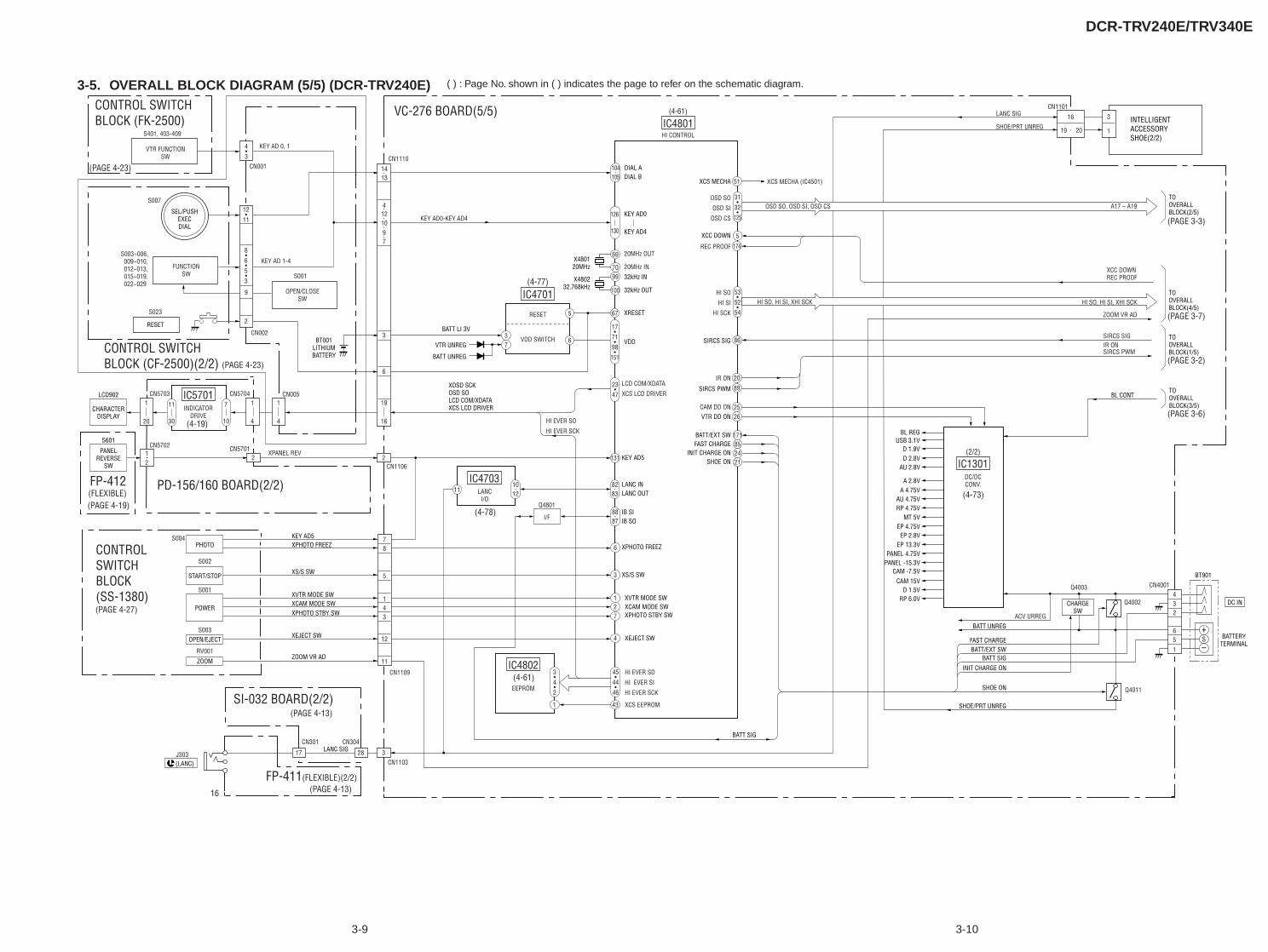
DCR-TRV240E/TRV340E
3-9 3-10
( ) : Page No. shown in ( ) indicates the page to refer on the schematic diagram.3-5. OVERALL BLOCK DIAGRAM (5/5) (DCR-TRV240E)
X480120MHz
X480232.768kHz
CHARACTERDISPLAY
LCD902
RESET
S601
PANELREVERSE
SW
KEY AD5XPHOTO FREEZ XPHOTO FREEZ
SEL/PUSHEXECDIAL
CN1110
KEY AD0-KEY AD4
CN5701
CN1106
XPANEL REV2 2
CN1103
16
32817
4•3
J303(LANC)
CONTROL SWITCHBLOCK (CF-2500)(2/2)
CONTROL SWITCHBLOCK (FK-2500)
CONTROLSWITCHBLOCK(SS-1380)
CN570212
CN0051
4
CN57041
4
CN57031
20
(FLEXIBLE)FP-412 PD-156/160 BOARD(2/2)
7
10
11
30
IC5701INDICATOR
DRIVE
VC-276 BOARD(5/5)
SI-032 BOARD(2/2)
FP-411(FLEXIBLE)(2/2)
14
41210
13
97
19
6
3
16
BT001LITHIUMBATTERY
CN301 CN304
CN1109
78
5
12
14
11
3
XS/S SW
XVTR MODE SWXCAM MODE SWXPHOTO STBY SW
XEJECT SW
ZOOM VR AD
LANC SIG
IC4701
RESET
VDD SWITCH
(4-77)
(4-19)
(4-78)
(4-73)
(4-61)
IC4801HI CONTROL
(4-61)
5
69
7099
100
67
6
131
11
6
3
127
4
431
37VTR UNREG
BATT UNREG
BATT LI 3V
5
86
20
89
51
174
171852421
KEY AD0
KEY AD4
DIAL ADIAL B
32kHz IN
32kHz OUT
VDD
KEY AD5
XOSD SCKOSD SOLCD COM/XDATAXCS LCD DRIVER
LANC INLANC OUT
IB SIIB SO
XS/S SW
XVTR MODE SWXCAM MODE SWXPHOTO STBY SW
BATT SIG
XEJECT SW
XRESET
8283
1012
8887
IC4703
I/F
LANCI/O
Q4801
BL CONT
104105
126
XCC DOWN
XCS MECHA
SIRCS PWM
2625
VTR DD ON
FAST CHARGEBATT/EXT SW
SHOE ONINIT CHARGE ON
SIRCS SIG
CN1101LANC SIG
SHOE/PRT UNREG
3
1
16
19 20
TOOVERALLBLOCK(4/5)
TOOVERALLBLOCK(2/5)
TOOVERALLBLOCK(1/5)
TOOVERALLBLOCK(3/5)
USB 3.1VBL REG
INTELLIGENTACCESSORYSHOE(2/2)
IC1301DC/DCCONV.
(2/2)D 1.9VD 2.8V
AU 2.8V
A 2.8VA 4.75V
AU 4.75VRP 4.75V
MT 5VEP 4.75VEP 2.8V
EP 13.3VPANEL 4.75V
PANEL -15.3VCAM -7.5V
CAM 15VD 1.5V
RP 6.0V
FAST CHARGE
BATT UNREG
SHOE/PRT UNREG
BATT/EXT SWBATT SIG
INIT CHARGE ON
SHOE ON
DC IN
+
–S BATTERY
TERMINAL
CHARGESW
CN4001Q4003
Q4011
Q4002432
651
(PAGE 4-27)
(PAGE 4-13)
(PAGE 4-13)
(PAGE 4-23)
(PAGE 4-23)
(PAGE 4-19)
12•
11
8•6•5•3
9
2
53•
52•
54
45•
44•
46
31•
32•
125
17•
71•
98•
151
23•
47
S023
CN002
CN001
S001
OPEN/CLOSESW
KEY AD 1-4FUNCTION
SW
S007
VTR FUNCTIONSW
S003~006, 009~010, 012~013, 015~019, 022~029
S401, 403-409
KEY AD 0, 1
IC4802
EEPROM
130
ZOOM VR AD
IR ONSIRCS PWM
SIRCS SIG
ACV URREG
3•4•2
OSD SO
OSD SI
OSD CS
REC PROOF20MHz OUT
20MHz IN
HI SO
HI SI
HI SCK
LCD COM/XDATA
XCS LCD DRIVER
HI EVER SD
HI EVER SI
HI EVER SCK
HI EVER SO
HI EVER SCK
XCS EEPROM
IR ON
CAM DD ON
HI SO, HI SI, XHI SCK HI SO, HI SI, XHI SCK
OSD SO, OSD SI, OSD CS
XCS MECHA (IC4501)
A17 – A19
XCC DOWNREC PROOF
(PAGE 3-3)
(PAGE 3-7)
(PAGE 3-2)
(PAGE 3-6)
PHOTO
START/STOP
POWER
OPEN/EJECT
ZOOM
S004
S002
S001
S003
RV001
BT901
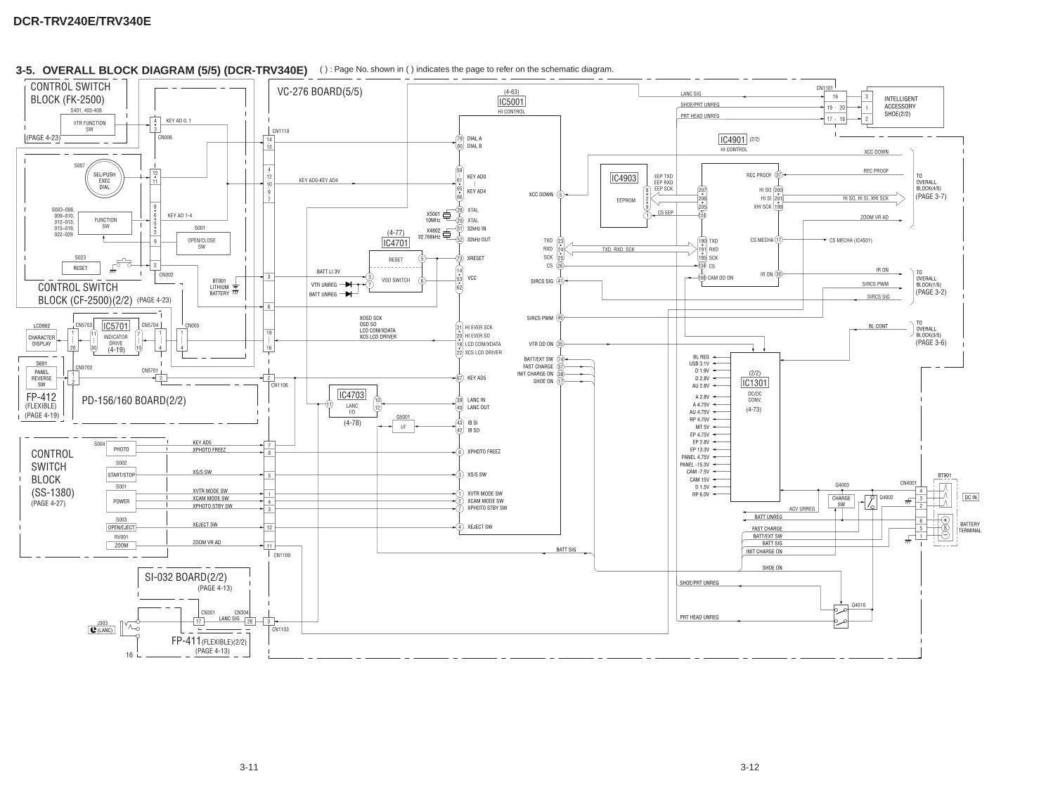
DCR-TRV240E/TRV340E
3-11 3-12
( ) : Page No. shown in ( ) indicates the page to refer on the schematic diagram.3-5. OVERALL BLOCK DIAGRAM (5/5) (DCR-TRV340E)
X500110MHz
X480232.768kHz
CHARACTERDISPLAY
LCD902
RESET
S601
PANELREVERSE
SW
PHOTO
START/STOP
POWER
OPEN/EJECT
KEY AD5XPHOTO FREEZ XPHOTO FREEZ
ZOOM
SEL/PUSHEXECDIAL
CN1110
KEY AD0-KEY AD4
CN5701
CN11062 2
CN1103
16
32817
4•3
J303
CONTROL SWITCHBLOCK (CF-2500)(2/2)
CONTROL SWITCHBLOCK (FK-2500)
CONTROLSWITCHBLOCK(SS-1380)
CN570212
CN0051
4
CN57041
4
CN57031
20
(FLEXIBLE)FP-412 PD-156/160 BOARD(2/2)
7
10
11
30
IC5701INDICATOR
DRIVE
VC-276 BOARD(5/5)
SI-032 BOARD(2/2)
FP-411(FLEXIBLE)(2/2)
14
41210
13
97
19
6
3
16
BT001LITHIUMBATTERY
CN301 CN304
CN1109
78
5
12
14
11
3
XS/S SW
XVTR MODE SWXCAM MODE SWXPHOTO STBY SW
XEJECT SW
ZOOM VR AD
LANC SIG
IC4701
RESET
VDD SWITCH
(4-77)
(4-19)
(4-78)
IC5001HI CONTROL
(4-63)
(4-73)
5
28
2951
52
73
6
67
11
6
3
127
4
37VTR UNREG
BATT UNREG
BATT LI 3V
5
41
45
26
74373817
KEY AD0
KEY AD4
DIAL ADIAL B
32kHz IN
32kHz OUT
VCC
KEY AD5
XOSD SCKOSD SOLCD COM/XDATAXCS LCD DRIVER
LANC INLANC OUT
IB SIIB SO
XS/S SW
XVTR MODE SWXCAM MODE SWXPHOTO STBY SW
BATT SIG
XEJECT SW
XRESET
3940
1012
4342
IC4703
I/F
LANCI/O
Q5001
BL CONT
7980
59
XCC DOWN
SIRCS PWM
35VTR DD ON
FAST CHARGEBATT/EXT SW
SHOE ONINIT CHARGE ON
SIRCS SIG
CN1101LANC SIG
SHOE/PRT UNREG
PRT HEAD UNREG
3
1
2
16
19
17
20
18
TOOVERALLBLOCK(4/5)
TOOVERALLBLOCK(1/5)
TOOVERALLBLOCK(3/5)
USB 3.1VBL REG
INTELLIGENTACCESSORYSHOE(2/2)
IC1301DC/DCCONV.
(2/2)
IC4903
IC4901
D 1.9VD 2.8V
AU 2.8V
A 2.8VA 4.75V
AU 4.75VRP 4.75V
MT 5VEP 4.75V
EP 2.8VEP 13.3V
PANEL 4.75VPANEL -15.3V
CAM -7.5VCAM 15V
D 1.5VRP 6.0V
FAST CHARGE
BATT UNREG
SHOE/PRT UNREG
PRT HEAD UNREG
BATT/EXT SWBATT SIG
INIT CHARGE ON
SHOE ON
DC IN
+
–S
BATTERYTERMINAL
CHARGESW
CN4001Q4003
Q4002
Q4010
432
651
(PAGE 4-27)
(PAGE 4-19)
(PAGE 4-23)
(PAGE 4-23)
(PAGE 4-13)
(PAGE 4-13)
12•
11
8•6•5•3
9
2
23•
24•
25
21•
20•
18•
22
14•
53•
62
8•2•9
207•
206•
205
200•
201•
199
190•
191•
185
124
134
168
1
37
17
30
S004
S002
S001
S003
RV001
S023
CN002
CN006
S001
OPEN/CLOSESW
KEY AD 1-4FUNCTION
SW
S007
VTR FUNCTIONSW
S003~006, 009~010, 012~013, 015~019, 022~029
S401, 403-409
KEY AD 0, 1
61•
65•
66
XTAL
XTAL
TXD
RXD
SCK
CS
TXD
RXD
SCK
CS
HI SO
HI SI
XHI SCK
HI EVER SCK
HI EVER SO
LCD COM/XDATA
XCS LCD DRIVER
EEPROM
TXD, RXD, SCK
HI CONTROL
EEP TXDEEP RXDEEP SCK
CS EEP
CAM DD ON
REC PROOF
CS MECHA
IR ON
XCC DOWN
REC PROOF
HI SO, HI SI, XHI SCK
ZOOM VR AD
CS MECHA (IC4501)
IR ON
SIRCS PWM
SIRCS SIG
(2/2)
ACV URREG
(PAGE 3-7)
(PAGE 3-2)
(PAGE 3-6)
(LANC)
BT901
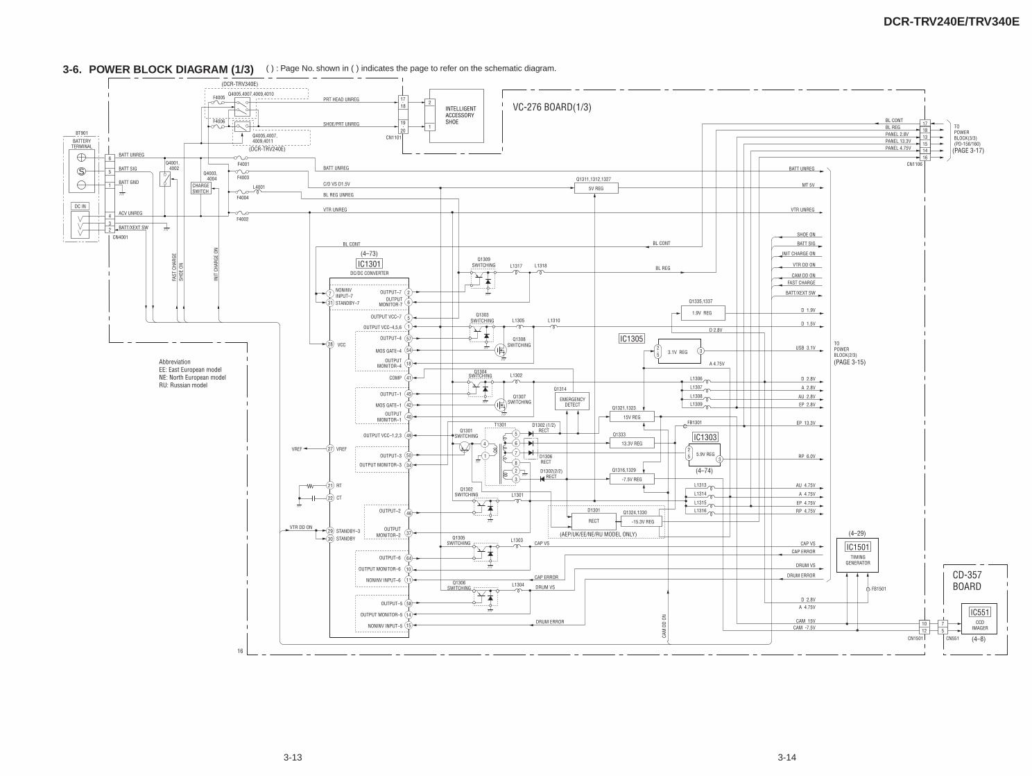
DCR-TRV240E/TRV340E
3-13 3-14
( ) : Page No. shown in ( ) indicates the page to refer on the schematic diagram.3-6. POWER BLOCK DIAGRAM (1/3)
S
7
31
28
2
6
5
1
57
54
18
41
45
42
40
49
50
34
276
7
2
3
46
37
21
22
29
30
64
10
11
58
14
15
1
4
5
8
IC1301
BATTERYTERMINAL
BT901
DC IN
Q4001, 4002
Q4003, 4004
Q4005,4007,4009,4011
Q4005,4007,4009,4010
(DCR-TRV240E)
(AEP/UK/EE/NE/RU MODEL ONLY)
(DCR-TRV340E)
F4001
F4005
F4003
F4004
F4002
CHARGESWITCH
C/D VS D1.5V
BL REG UNREG
VTR UNREG
BL CONT
DC/DC CONVERTER
(4–73)
(4–74)
(4–29)
(4–8)
(PAGE 3-15)
(PAGE 3-17)
STANDBY–7
NONINVINPUT–7
OUTPUT–7
MONITOR-7OUTPUT
OUTPUT VCC–7
OUTPUT VCC–4,5,6
OUTPUT–4
MOS GATE–4
OUTPUTMONITOR–4
OUTPUT–1
MOS GATE–1
OUTPUTMONITOR–1
VCC
COMP
VREF
VTR DD ON
16
VREF
OUTPUT VCC–1,2,3
OUTPUT–3
OUTPUT MONITOR–3
RT
CT
OUTPUT–2
OUTPUTMONITOR–2
OUTPUT–6
OUTPUT MONITOR–6
NONINV INPUT–6
OUTPUT–5
OUTPUT MONITOR–5
NONINV INPUT–5
STANDBY–3STANDBY
VTR DD ON
SHOE ON
BATT SIG
BATT/XEXT SW
FAST CHARGE
INIT CHARGE ON
CAM DD ON
BL CONT
BL REG
VTR UNREG
MT 5V
BATT UNREG
DRUM ERROR
D 2.8VA 4.75V
CAM 15VCAM -7.5V
DRUM VS
CAP ERROR
CAP VS
Q1303SWITCHING
Q1308SWITCHING
Q1307SWITCHING
Q1304SWITCHING
Q1301SWITCHING
Q1302SWITCHING
Q1305SWITCHING
Q1306SWITCHING
L1305 L1310
L1306
L1307
D 1.9V
D 1.5V
USB 3.1V
D 2.8V
A 2.8V
L1302
T1301
Q1314
D1302 (1/2)RECT
D1306RECT
D1302(2/2)RECT
D1301
RECT
EMERGENCYDETECT
-7.5V REG
Q1316,1329
-15.3V REG
Q1324,1330
13.3V REG
Q1333
15V REG
Q1321,1323
5V REG
Q1311,1312,1327
L1301
L1303
L1304
CAP VS
CAM
DD
ON
CAP ERROR
DRUM VS
DRUM ERROR
BATT UNREG
L1317
L4001
L1318Q1309
SWITCHING
SHOE/PRT UNREG
PRT HEAD UNREG
CN1101
TOPOWERBLOCK(3/3)(PD-156/160)
CN1106
TOPOWERBLOCK(2/3)
BL CONTBL REGPANEL 2.8VPANEL 13.3VPANEL 4.75V
17
13151416
18
CN4001
FAST
CHA
RGE
SHOE
ON
INIT
CHA
RGE
ON
BATT GND
BATT UNREG
BATT SIG
BATT/XEXT SW
ACV UNREG
6
5
1
432
F4006
VC-276 BOARD(1/3)2
1
INTELLIGENTACCESSORYSHOE
17
20
18
19
IC1305
Q1335,1337
IC1501TIMING
GENERATOR
IC551CCD
IMAGER
IC1303
5.9V REG
L1308 AU 2.8V
L1309
L1313
L1314
L1315
L1316
FB1301
EP 2.8V
AU 4.75V
A 4.75V
EP 4.75V
RP 4.75V
EP 13.3V
RP 6.0V3
3
25
25
FB1501
CN551CN1501
1012
75
CD-357BOARD
1.9V REG
3.1V REG
D 2.8V
A 4.75VAbbreviationEE: East European modelNE: North European modelRU: Russian model
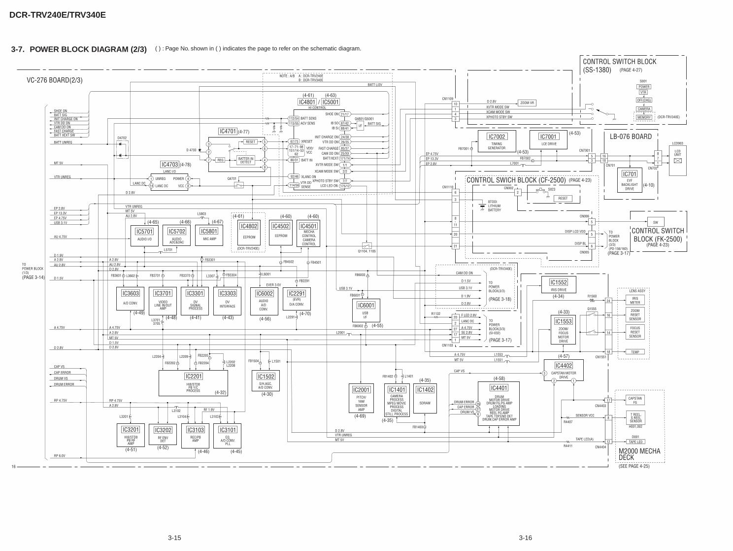
DCR-TRV240E/TRV340E
3-15 3-16
( ) : Page No. shown in ( ) indicates the page to refer on the schematic diagram.3-7. POWER BLOCK DIAGRAM (2/3)
8
11
4
8
1
3
2
112/54113/55
67/73
14
IC4703REG
UNREG
LANC I/O
LANC DCLANC DC
POWER
VCC
(4-78)
IC5701AUDIO I/O
(4-65)
IC4701 (4-77)
(4-61) (4-63)
(4-53)
(4-53)
IC4801 IC5001
(4-34)
(4-33)
(4-57)
(4-10)
(PAGE 4-27)
(PAGE 4-23)
(PAGE 4-23)
(PAGE 3-17)
(PAGE 3-17)
D4702
Q4701
5
6
4
8
7 BATTER INDETECT
RESET
HI CONTROL
BATT SENSSHOE ON
IB SOIB SI
ACV SENS
XRESET
VDD/VCC
INIT CHARGE ONVTR DD ON
FAST CHARGECAM DD ONBATT/XEXT
XVTR MODE SW
XCAM MODE SW
XPHOTO STBY SW
BATT IN
XLANC ON
17 71 98151/14 53
62
Q4801/Q5001BATT SIG
BATT LI3V
I/F
IC5702AUDIO
L5701
(4-66)
IC5801MIC AMP
(4-67)
ADC&DAC
(4-52)(4-51)
IC3202
DETRF ENV
IC2201
PB Y/CPROCESS
HI8/STD8
(4-32) (4-30)
(4-69)
(4-55)
(4-35)
(4-35)
IC1502
A/D CONV.S/H,AGC,
IC3603
(4-49)
A/D CONV.
IC2291(EVR)
D/A CONV.
IC3301IC3701
(4-48)
VIDEOLINE IN/OUT
AMP
(4-41)
DVSIGNAL
PROCESS
IC3103REC/PB
AMP
IC3101
(4-45)(4-46)
EQ.A/D CONV.
PLL
IC6002
(4-70)(4-56)
(4-60)(4-61) (4-60)
FB3601 FB3701 FB3370
FB2202
SHOE ONBATT SIGINIT CHARGE ONVTR DD ONCAM DD ONFAST CHARGEBATT XEXT SW
EP 2.8VEP 13.3VEP 4.75VUSB 3.1V
CAP VS
CAP ERROR
DRUM VS
DRUM ERROR
AU 4.75V
AU 2.8V
D 2.8V
D 4703
D 1.9VA 2.8V A 2.8V
AU 2.8VAU 2.8V
D 1.5V
D 1.5V
EVER 3.0V
A 4.75V A 4.75V
D 2.8V D 2.8V
D 2.8V
RP 4.75V RP 4.75VA 2.8V
A 2.8V
RP 6.0V
16
TOPOWER BLOCK(1/3)(PAGE 3-14)
BATT UNREG
MT 5V
MT 5V
MT 5V
VTR UNREG
VTR UNREG
VTR UNREGMT 5V
D 2.8V
L3102
L3201 L3104 L3103
RF 1.9V
IC3201
PB RFAMP
HI8/STD8
L2202L2208
L1501FB1504FB2204
FB2291
FB4501
IC1401 IC1402 IC4401
MOTOR DRIVEDRUM FG,PG AMP
DRUM
(4-58)
MOTOR DRIVEREEL FG AMP
LOADINGDRUM ERROR
DRUM,CAP ERROR AMPTAPE TOP,END DET
CAP VS
MT 5V
CAP ERRORDRUM VS
FB2205L2204
L2291
VC-276 BOARD(2/3)
M2000 MECHADECK
62729
17CN4403
R4407
SENSOR VCC
TAPE LED(A)
IRISMETER
CAPSTANFG
TEMP
ZOOMRESET
SENSOR
FOCUSRESET
SENSOR
8
H001,002
D00112
CN4404
T REEL,S REEL
SENSOR
TAPE LED
(SEE PAGE 4-25)
R4411
80/31
92/46
114/56
L3602
L5803
IC4502EEPROM
IC4802 IC4501
L3701, 3705
IC3303
(4-43)
DVINTERFACE
L2209
IC6001
110
43
TOPOWERBLOCK(3/3)(PD-156/160)
TOPOWERBLOCK(3/3)
CN701
1618
53
CN1103
27
2
20
17
1
D 1.5V
USB 3.1V
D 2.8V
F LED 2.8VR1132
XPHOTO STBY SW
POWER
VTR
OFF(CHG)
CAMERA
MEMORY
CN702
871
CN1110
6 2
3
21
20
6
5
5
XCAM MODE SWXVTR MODE SW
EP 2.8VEP 13.3VEP 4.75V
LB-076 BOARD
CONTROL SWITCH BLOCK(SS-1380)
LCD
LCD903
SW
UNIT
IC701EVF
BACKLIGHTDRIVE
IC7002 IC7001
A 4.75VSE 2.8VMT 5V
TOPOWERBLOCK(3/3)(SI-032)
Q1555
R1560
3
2 1
IC4402CAPSTAN MOTOR
DRIVE
IC1552IRIS DRIVE
IC1553ZOOM/FOCUSMOTORDRIVE
IC2001PITCH/YAW
SENSORAMP
CN1551
24
LENS ASSY
16
14
18
L1551
L2001
A 4.75V L1553
87/42
21/17
88/41
24/3826/35
85/3725/XX171/74
1/1
2/2
7/7175/12
VTR DDSENSE LCD LED ON
/
LANC DC
(PAGE 3-18)
FB3301
D 1.9V
CAM DD ON(DCR-TRV340E)
FB7001
CN1109
TIMINGGENERATOR
LCE DRIVE
CN7001
FB7002L7001
BTOOILITHIUMBATTERY
DISP LCD VDD
CN005
CN006
DISP BL
CN002
CONTROL SWICH BLOCK (CF-2500)S023
RESET
ZOOM VR
CONTROL SWITCHBLOCK (FK-2500)
S001
D 2.8V
NOTE : A/B A : DCR-TRV240EB : DCR-TRV340E
USB 3.1V
(DCR-TRV340E)
L3307 L6001FB3304
EEPROM
(DCR-TRV240E)
FB4502
FB6003
FB6001
FB6002
AUDIOA/D
CONV.USBI/F
MECHACONTROLCAMERACONTROL
Q1104, 1105
FB1402 L1401
SDRAM
FB1403
CAMERAPROCESS
MPEG MOVIEPROCESSDIGITAL
STILL PROCESS
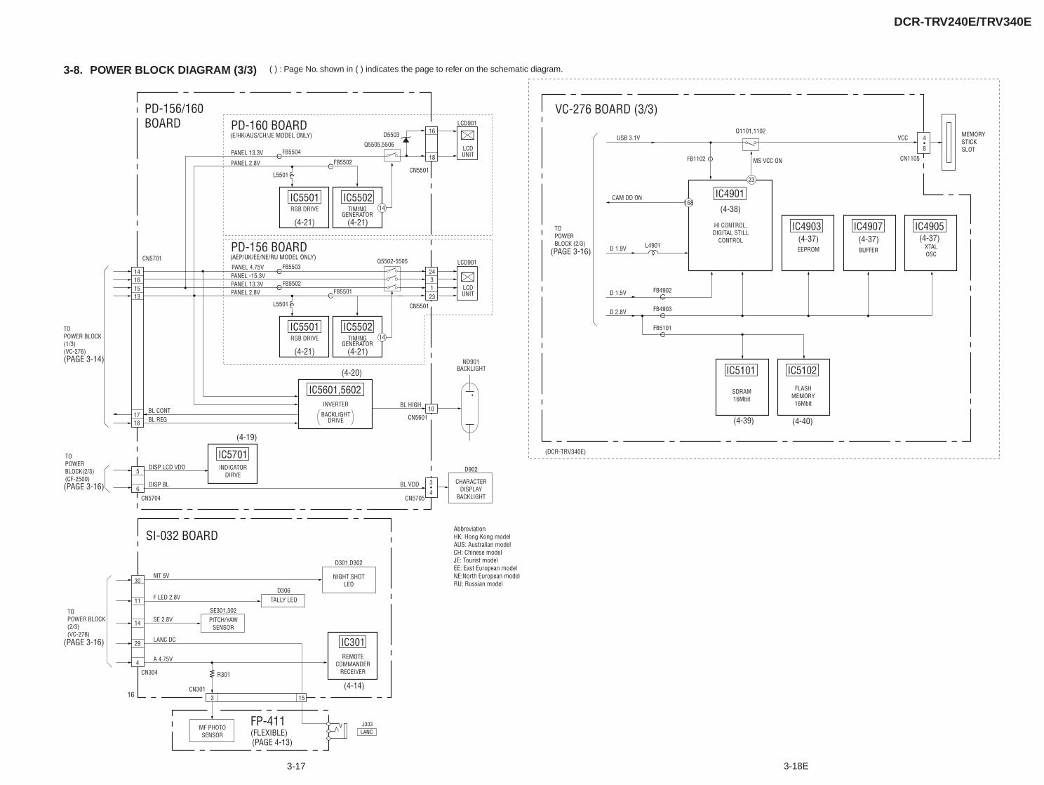
DCR-TRV240E/TRV340E
3-17 3-18E
( ) : Page No. shown in ( ) indicates the page to refer on the schematic diagram.3-8. POWER BLOCK DIAGRAM (3/3)
IC5101 IC5102
IC4907IC4903 IC4905
(PAGE 3-14)
(PAGE 3-16)
(PAGE 3-16)
(PAGE 3-16)
(PAGE 4-13)
(4-39) (4-40)
(4-14)
(4-20)
(4-19)
(4-38)
(4-37) (4-37) (4-37)
IC5701INDICATOR
DIRVE
IC301REMOTE
COMMANDERRECEIVER
PITCH/YAWSENSOR
IC5601,5602INVERTER
BACKLIGHT
BACKLIGHT
DRIVE
CN5701
BL CONT
TOPOWERBLOCK(2/3)(CF-2500)
BL REG
Q5505,5506
D5503
14
1516
13
5
6
1718
CN5501
16
18LCD
LCD901
(4-21) (4-21)
UNIT
10CN5601
CN5705
BL HIGH
BL VDD 3•4
ND901
DISP LCD VDD
DISP BL
CN5704
PD-156/160BOARD PD-160 BOARD
VC-276 BOARD (3/3)
PANEL 13.3V
PANEL 4.75V
FB5504
IC5502GENERATOR
TIMING
IC5501RGB DRIVE
PANEL 2.8V
L5501
14
FB5502
MF PHOTOSENSOR
NIGHT SHOTLED
CHARACTERDISPLAY
BACKLIGHT
D902
CN304
16CN301
R301
A 4.75V
SE 2.8V
MT 5V
D301,D302
SE301,302
TALLY LEDD306
TOPOWER BLOCK(2/3)(VC-276)
TOPOWER BLOCK(1/3)(VC-276)
30
14
4
3 15
FP-411(FLEXIBLE)
SI-032 BOARD
F LED 2.8V11
LANC DC29
J303LANC
23
168
EEPROM
IC4901
HI CONTROL,DIGITAL STILL
CONTROL
BUFFER
SDRAM16Mbit
FLASHMEMORY
16Mbit
D 1.5V
D 2.8V
FB4902
FB4903
FB5101
D 1.9V L4901
CAM DD ON
USB 3.1V
FB1102
Q1101,1102
MS VCC ON
TOPOWERBLOCK (2/3)
VCC
CN1105
XTALOSC
MEMORYSTICKSLOT
4•8
(DCR-TRV340E)
(E/HK/AUS/CH/JE MODEL ONLY)
Q5502-5505
CN5501
243123
LCD
LCD901
(4-21) (4-21)
UNIT
PD-156 BOARD
PANEL 13.3VPANEL -15.3V
FB5502
FB5503
IC5502GENERATOR
TIMING
IC5501RGB DRIVE
PANEL 2.8V
L5501
14
FB5501
(AEP/UK/EE/NE/RU MODEL ONLY)
AbbreviationHK: Hong Kong modelAUS: Australian modelCH: Chinese modelJE: Tourist modelEE: East European modelNE:North European modelRU: Russian model
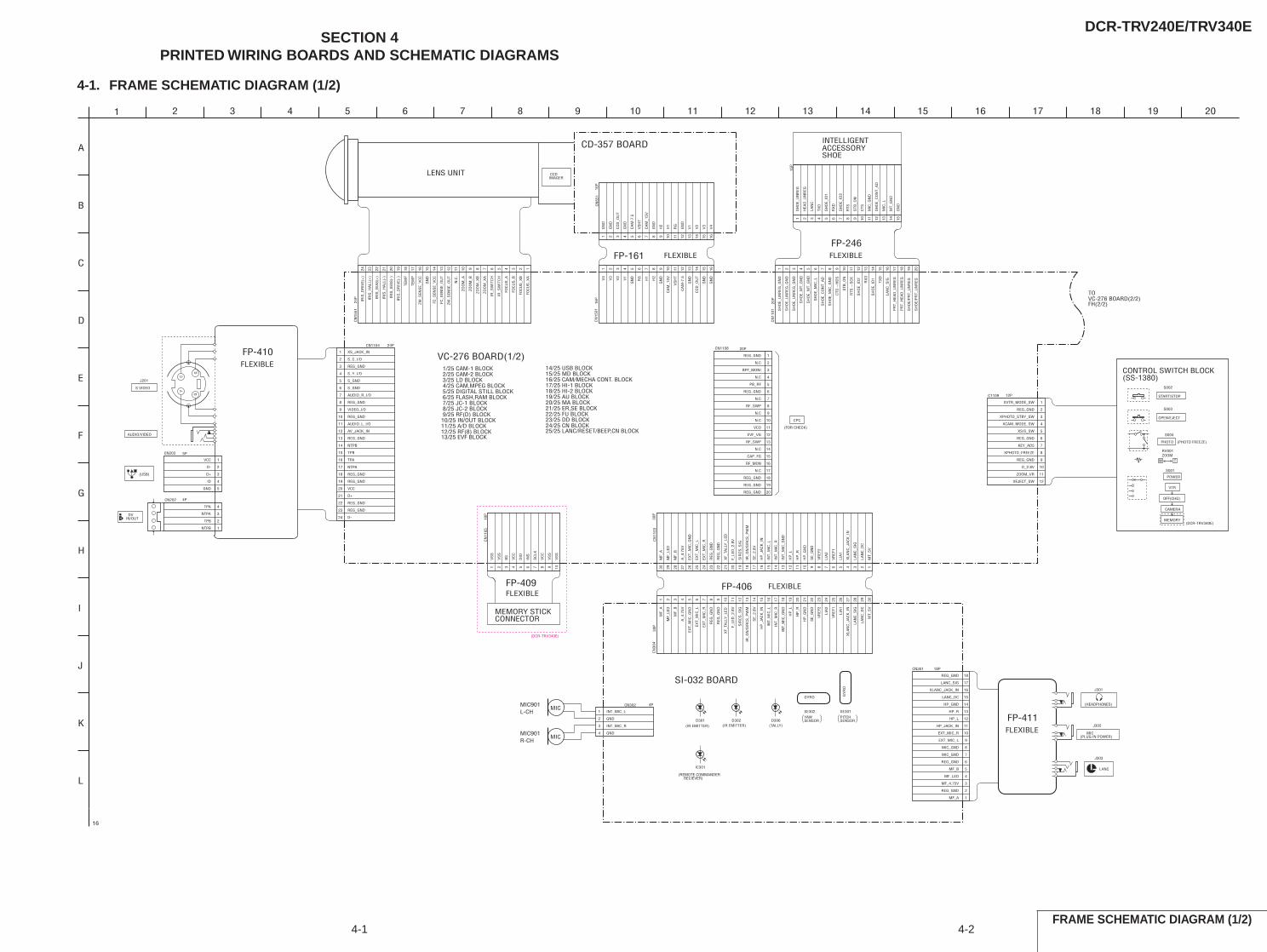
DCR-TRV240E/TRV340ESECTION 4
PRINTED WIRING BOARDS AND SCHEMATIC DIAGRAMS
4-1. FRAME SCHEMATIC DIAGRAM (1/2)
FRAME SCHEMATIC DIAGRAM (1/2)4-1 4-2
24P
CN
1551
123456789101112131415161718192021222324
20P
CN
1101
1 2 3 4 5 6 7 8 9 10 11 12 13 14 15 16 17 18 19 20
15P
1 2 3 4 5 6 7 8 9 10 11 12 13 14 15
10P
CN
1105
1 2 3 4 5 6 7 8 9 10
18PCN301
1
2
3
4
5
6
7
8
9
10
11
12
13
14
15
16
17
18
20PCN1108
1
2
3
4
5
6
7
8
9
10
11
12
13
14
15
16
17
18
19
20
Y
GG
C
J201
4PCN202
1NTPB
2TPB
3NTPA
4TPA
4PCN302
1
2
3
4
24PCN1104
1
2
3
4
5
6
7
8
9
10
11
12
13
14
15
16
17
18
19
20
21
22
23
24 30P
CN
1103
123456789101112131415161718192021222324252627282930
30P
CN
304
1 2 3 4 5 6 7 8 9 10 11 12 13 14 15 16 17 18 19 20 21 22 23 24 25 26 27 28 29 30
D302
1
A
S002
5PCN203
1VCC
2D-
3D+
4ID
5GND
16P
CN
551
1 2 3 4 5 6 7 8 9 10 11 12 13 14 15 16
16P
CN
1501
1V
4
2V
3
3V
2
4V
1
5G
ND
6R
G
7H
1
8H
2
9G
ND
10C
AM
_15V
11V
SH
T
12C
AM
-7.5
13G
ND
14C
CD
_OU
T
15G
ND
16G
ND
12PC1109
1
2
3
4
5
6
7
8
9
10
11
12
S003
RV001
S004
D301 D306
J301
J303
J302
IC301
FOC
US
_XA
FOC
US
_XB
FOC
US
_B
FOC
US
_A
IR_S
WIT
CH
IR_S
WIT
CH
ZOO
M_X
A
ZOO
M_X
B
ZOO
M_B
ZOO
M_A
N.C
.
ZM_S
ENS
E_O
UT
FC_S
ENS
E_O
UT
FC_S
ENS
E_V
CC
GN
D
ZM_S
ENS
E_V
CC
TEM
P
TEM
P
IRIS
_DR
IVE(
-)
IRIS
_BIA
S(-
)
IRIS
_HA
LL(-
)
IRIS
_BIA
S(+
)
IRIS
_HA
LL(+
)
IRIS
_DR
IVE(
+)
GYRO GY
RO
SH
OE_
UN
REG
_GN
D
SH
OE_
UN
REG
_GN
D
SH
OE_
MIC
_GN
D
SH
OE_
UN
REG
_GN
D
SH
OE_
MIC
_L
STB
_ON
SH
OE/
PR
T_U
NR
EG
SH
OE/
PR
T_U
NR
EG
SH
OE_
MT_
GN
D
SH
OE_
MT_
GN
D
PR
T_H
EAD
_UN
REG
PR
T_H
EAD
_UN
REG
LAN
C_S
IGTXD
SH
OE_
ID1
RX
D
SH
OE_
ID2
RTS
→S
CK
CTS
→H
DS
SH
OE_
CO
NT_
AD
SH
OE_
UN
REG
HEA
D_U
NR
EG
LAN
C
TXD
SH
OE_
ID1
RX
D
SH
OE_
ID2
RTS
STB
_ON
CTS
MIC
_GN
D
SH
OE_
CO
NT_
AD
MIC
_L
MT_
GN
D
GN
D
DIO
BS
VC
C
SC
LK
VS
S
INS
VC
C
VS
S
VS
S
VS
S
EXT_MIC_L
REG_GND
MIC_GND
HP_R
MF_B
HP_L
LANC_SIG
REG_GND
HP_GND
MIC_GND
XLANC_JACK_IN
MF_LED
MF_A
EXT_MIC_R
LANC_DC
REG_GND
HP_JACK_IN
MF_4.75V
VCO
PB_RF
EVF_VG
REG_GND
CAP_FG
RF_SWP
BPF_MONI
RF_MON
REG_GND
REG_GND
N.C
N.C
N.C
N.C
N.C
N.C
RF_SWP
REG_GND
REG_GND
N.C
GND
GND
INT_MIC_R
INT_MIC_L
FP-406
REG_GND
TPB
D+
S_Y_I/O
REG_GND
REG_GND
VIDEO_I/O
REG_GND
AUDIO_R_I/O
XS_JACK_IN
S_GND
AUDIO_L_I/O
REG_GND
REG_GND
REG_GND
S_C_I/O
REG_GND
S_GND
NTPA
AV_JACK_IN
D-
TPA
VCC
NTPB
LIA
1
SIR
CS
_SIG
MF_
B
IR_O
N/S
IRC
S_P
WM
HP
_L
SE_
GN
D
EXT_
MIC
_GN
D
HP
_L
HP
_GN
D
LAN
C_S
IG
MF_
LED
MT_
5V
MF_
LED
VR
EF1
MT_
5V
REG
_GN
D
INT_
MIC
_R
LAN
C_D
C
MF_
A
F_LE
D_2
.8V
REG
_GN
D
EXT_
MIC
_L
VR
EF2
REG
_GN
D
INT_
MIC
_L
XF_
TALL
Y_L
ED
LAN
C_D
C
XLA
NC
_JA
CK
_IN
SE_
2.8V
REG
_GN
D
INT_
MIC
_GN
D
LAN
C_S
IG
XLA
NC
_JA
CK
_IN
HP
_JA
CK
_IN
MF_
A
EXT_
MIC
_GN
D
INT_
MIC
_GN
D
HP
_R
EXT_
MIC
_R
SE_
GN
D
INT_
MIC
_L
VR
EF1
XF_
TALL
Y_L
ED
INT_
MIC
_R
LIA
2
IR_O
N/S
IRC
S_P
WM
LIA
1
EXT_
MIC
_R
SE_
2.8V
HP
_R
SIR
CS
_SIG
A_4
.75V
VR
EF2
HP
_GN
D
LIA
2
F_LE
D_2
.8V
EXT_
MIC
_L
A_4
.75V
MF_
B
HP
_JA
CK
_IN
FLEXIBLE
PITCHSENSOR
AUDIO/VIDEO
17
S VIDEO
19
E
SE302
L
MIC
I
MIC901
G
(IR EMITTER)
START/STOP
(USB)
7
VC-276 BOARD(1/2)
TOVC-276 BOARD(2/2)FH(2/2)
FP-161
LENS UNIT
(FOR CHECK)
C
16
K
CPC
16
CONTROL SWITCH BLOCK(SS-1380)
12
B
3
FP-410
CD-357 BOARD
20
FLEXIBLE
6
J
H
1054 132
D
F
CCDIMAGER
SE301
1511
SI-032 BOARD
9
YAWSENSOR
8 14 18
DVIN/OUT
VS
HT
V2
H2
GN
D
RG
H1
GN
D
GN
D
GN
D
CC
D_O
UT
V4
V3
CA
M-7
.5
GN
D
V1
CA
M_1
5V
INTELLIGENTACCESSORYSHOE
REG_GND
KEY_AD5
XVTR_MODE_SW
XCAM_MODE_SW
XEJECT_SW
XPHOTO_STBY_SW
XPHOTO_FREEZE
ZOOM_VR
REG_GND
D_2.8V
REG_GND
XS/S_SW
OPEN/EJECT
S001
CAMERA
OFF(CHG)
T
(PHOTO FREEZE)
VTR
PHOTO
W
POWER
MEMORY
ZOOM
FLEXIBLE
MEMORY STICKCONNECTOR
(DCR-TRV340E)
FLEXIBLEFP-409
MIC901MIC
L-CH
R-CH
(IR EMITTER) (TALLY)
MIC(PLUG IN POWER)
LANC
(HEADPHONES)
FP-411FLEXIBLE
FP-246FLEXIBLE
1/25 CAM-1 BLOCK 2/25 CAM-2 BLOCK 3/25 LD BLOCK 4/25 CAM,MPEG BLOCK 5/25 DIGITAL STILL BLOCK 6/25 FLASH,RAM BLOCK 7/25 JC-1 BLOCK 8/25 JC-2 BLOCK 9/25 RF(D) BLOCK10/25 IN/OUT BLOCK11/25 A/D BLOCK12/25 RF(8) BLOCK13/25 EVF BLOCK
14/25 USB BLOCK15/25 MD BLOCK16/25 CAM/MECHA CONT. BLOCK17/25 HI-1 BLOCK18/25 HI-2 BLOCK19/25 AU BLOCK20/25 MA BLOCK21/25 ER,SE BLOCK22/25 FU BLOCK23/25 DD BLOCK24/25 CN BLOCK25/25 LANC/RESET/BEEP,CN BLOCK
(REMOTE COMMANDER RECIEVER)
(DCR-TRV340E)
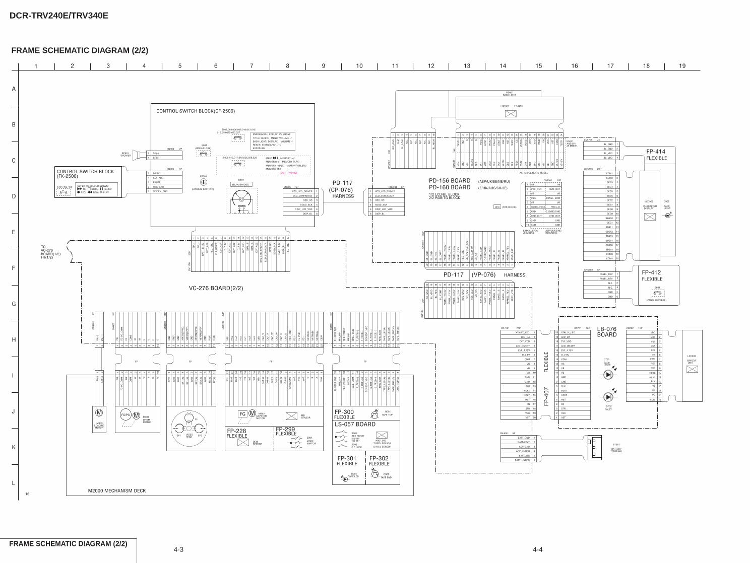
DCR-TRV240E/TRV340E
4-3 4-4
FRAME SCHEMATIC DIAGRAM (2/2)
FRAME SCHEMATIC DIAGRAM (2/2)
CN44
0210
P
1 2 3 4 5 6 7 8 9 10
CN44
0415
P
1 2 3 4 5 6 7 8 9 10 11 12 13 14 15
16PCN702
1
COM
2
VG
3
VR
4
VB
5
BLK
6
HCK1
7
HCK2
8
HST 9
RGT
10
DWN
11
EN
12
STB
13
VCK
14
VST
15
VSS
16
VDD
6PCN5704
1
2
3
4
5
6
6PCN5702
1
2
3
4
5
6
10P
CN
5601
1LE
D_G
ND
2LE
D
3B
L_LO
W
4N
.C.
5N
.C.
6N
.C.
7N
.C.
8N
.C.
9N
.C.
10B
L_H
IGH
24P
CN
5501
1 2 3 4 5 6 7 8 9 10 11 12 13 14 15 16 17 18 19 20 21 22 23 24
2PC
N44
01
1 2
11P
CN
3101
1 2 3 4 5 6 7 8 9 10 11
22P
CN
4403
1 2 3 4 5 6 7 8 9 10 11 12 13 14 15 16 17 18 19 20 21 22
6PCN4001
1
2
3
4
5
6
10PCN5502
1
2
3
4
5
6
7
8
9
10
CN
1106
20P
1234567891011121314151617181920
20P
CN
5701
1234567891011121314151617181920
6PCN005
1
2
3
4
5
6
CN5703
1
2
3
4
5
6
7
8
9
10
11
12
13
14
15
16
17
18
19
20
4PCN5705
1
2
3
4
5PCN006
1
2
3
4
5
20PCN7001
1
2
3
4
5
6
7
8
9
10
11
12
13
14
15
16
17
18
19
20
20PCN701
1
2
3
4
5
6
7
8
9
10
11
12
13
14
15
16
17
18
19
20
22P
CN
1110
1 2 3 4 5 6 7 8 9 10 11 12 13 14 15 16 17 18 19 20 21 22
2PCN004
1
2
S401,403-409
S001
S003,004,006,009,010,012,015
S005,013,017,018,026,028,029
1 2
Q002
Q001
S601
1
A
PG
FG-P
G_C
OM
FG CO
M
W W V V U ULM(-
)
LM(+
)
C_L
OC
K_S
W
TAP
E_LE
D(K
)
S_R
EEL(
+)
HI8
_MP
REG
_GN
D
SEN
SO
R_V
CC
TAP
E_EN
D(C
)
ME/
MP
T_R
EEL(
+)
REC
_PR
OO
F
S_R
EEL(
-)
T_R
EEL(
-)
TAP
E_TO
P(C
)
HA
LL_C
OM
TAP
E_LE
D(A
)
XOSD_SCK
XCS_LCD_DRIVER
DISP_LCD_VDD
DISP_BL
LCD_COM/XDATA
OSD_SO
PANEL_REV
GND
BATT_GND
BATT_SIG
BATT_UNREG
ACV_GND
ACV_UNREG
GN
D
GN
D
GN
D
XO
DD
(SP
1X)
YO
DD
(SP
1Y)
GN
D
XEV
EN(S
P2X
)
YEV
EN(S
P2Y
)
GN
D
FE(Y
)
FE(X
)
Hw
2
Hw
1
Hv2
Hv1
Hu2
Hu1
VH
-
VH
+
CA
P_W
CA
P_W
CA
P_V
CA
P_U
REG
_GN
D
FG V
CC
FG2
FG1
M-S
W(C
)
M-S
W(B
)
M-S
W(A
)
DEW
CA
P_V
CA
P_U
V
FG-P
G_C
OM V
PG UFG U
CO
M WW
GN
D
SP
2(X
)
GN
D
SP
2(Y
)
GN
D
GN
D
GN
D
FE(Y
)
SP
1(X
)
FE(X
)
SP
1(Y
)
Vo2
Hw
1
Coi
l-U
coil-
V
Vo1
Hv2
Coi
l-V C
Hv1
Coi
l-W B
Hu2
Coi
l-U A
Hu1
GN
D(C
OM
)
DEWVH
-
Vcc
Hw
2
Coi
l-W
VH
+
HA
LL_C
OM
S_R
EEL(
-)
TAP
E_LE
D(A
)
C_L
OC
K_S
W
TAP
E_TO
P(C
)
REC
_PR
OO
F
T_R
EEL(
-)
TAP
E_LE
D(K
)
T_R
EEL(
+)
REG
_GN
D
ME/
MP
TAP
E_EN
D(C
)
HI8
_MP
SEN
SO
R_V
CC
S_R
EEL(
+)
BATT/XEXT
VB
XVD_OUT
VG
PSIG
VR
MAKER_CHECK
XHD
XHD_OUT
GND
GND
PANEL_REV
N.C.
GND
TES
T2
RG
T B R G
PS
IG
HC
K1
HC
K2
CR
ext
SO
UT
REF
HS
T
WID
E
CS
VV
SS
G
VD
OG
VS
S
VD
D
DW
N EN
VC
K
VS
T
CO
M
TES
T1
XP
AN
EL_R
EV
PA
NEL
_4.7
5V
PA
NEL
_HO
LD
SE_
GN
D
VD
_SC
K
XC
S_L
CD
PA
NEL
_13.
3V
BL_
CO
NT
VD
_SO
PA
NEL
_-15
.3V
PA
NEL
_R
BL_
GN
D
PA
NEL
_XH
D
XR
ST_
VTR
PA
NEL
_2.8
V
PA
NEL
_G
PA
NEL
_B
PA
NEL
_XV
D
REG
_GN
D
BL_
REG
XS
YS
_RS
T
PA
NEL
_HO
LD
PA
NEL
_R
BL_
GN
D
PA
NEL
_13.
3V
VD
_SC
K X
VC
_SC
K
VC
_SO
BL_
CO
NT
PA
NEL
_4.7
5V
BL_
REG
PA
NEL
_-15
.3V
XP
AN
EL_R
EV
REG
_GN
D
PA
NEL
_XV
D
PA
NEL
_G
XC
S_L
CD
_DA
SE_
GN
D
PA
NEL
_B
PA
NEL
_2.8
V
C-S
YN
C/X
HD
LCD_COM/XDATA
DISP_BL
XOSD_SCK
DISP_LCD_VDD
XCS_LCD_DRIVER
OSD_SO
N.C.
SEG10
SEG1
BL_GND
SEG14
SEG2
COM2
COM1
COM3
BL_GND
SEG4
SEG3
SEG8
BL_VDD
COM4
SEG12
SEG16
SEG5
BL_VDD
SEG9
SEG11
SEG15
SEG7
SEG6
SEG13
D2.8V
KEY_AD0
SEIDEN_GND
PAUSE
REG_GND
HCK2
GND
GND
EVF_4.75V
EVF_VDD
D_2.8V
VR
HCK1
VCK
VB
VG
EN
COM
STB
LED_ON/OFF
HST
LED_DA
VST
BLK
XTALLY_LED
VR
D_2.8V
EN
GND
VST
STB
EVF_VDD
GND
VB
VG
EVF_4.75V
LED_DA
LED_ON/OFF
BLK
HCK2
COM
HCK1
XTALLY_LED
HST
VCK
KEY
_AD
1
XO
SD
_SC
K
KEY
_AD
2
KEY
_AD
4
DIA
L_A
XC
S_L
CD
_DR
IVER
REG
_GN
D
D_2
.8V
LCD
_CO
M/X
DAT
A
SP
_+
KEY
_AD
3
BAT
T_LI
_3V
KEY
_AD
2
DIS
P_B
L
XH
I_R
ESET
SP
_-
EVER
_3.0
V
KEY
_AD
0
REG
_GN
D
D_2
.8V
OS
D_S
O
DIA
L_B
TOVC-276BOARD(1/2)FH(1/2)
LB-076BOARD
PD-160 BOARD
VC-276 BOARD(2/2)
1/2 LCD/BL BLOCK2/2 RGB/TG BLOCK
CONTROL SWITCH BLOCK(CF-2500)
SP901SPEAKER
SP(-)
SP(+)
CONTROL SWITCH BLOCK(FK-2500)
SUPER NS,COLOUR SLOWS/FF/ STOP/ PAUSE/
REC/ REW/ PLAY
(OPEN/CLOSE)
BT001
(LITHIUM BATTERY)
SEL/PUSH EXEC
016,019,022-025,027END SEARCH/
EXPOSURE
FOCUS/ PB ZOOM/
TITLE/ FADER/ MENU/ VOLUME +/BACK LIGHT/ DISPLAY/
EDITSEARCH+/ -/RESET/VOLUME -/
MPEG / MEMORY(+)/MEMORY(-)/ MEMORY PLAY/
MEMORY INDEX/ MEMORY DELETE/MEMORY MIX
(DCR-TRV340E)
LM(+
)
LM(-
)
TAPE TOP
TAPE LED
M2000 MECHANISM DECK
M901MM
FLEXIBLE
SP1
S REEL SENSOR
TAPE END
LOADING MOTOR
FP-301
LS-057 BOARDM903
FLEXIBLE
C.C.LOCK
FG/PG
VIDEOHEAD
S002
FP-302
H001,002
FP-300FLEXIBLE
T REEL SENSOR
S001
DRUMMOTOR
FE
SP2 REC PROOFME/MPHi8 MP
FP FPFPFP
2 8 117 3 9231 69 584 6 7 10415 10 12 121517 414 13 31618 1011 9 819 57 62122 20 10 9 315 113 261214 11 7 58 4
(CP-076)HARNESS
LCD901 2.5INCH
BACK LIGHTND901
(FOR CHECK)CPC
20P
LCD902
CHARACTER DISPLAY
(PANEL REVERSE)
FLEXIBLEFP-412
D902
BACKLIGHT
HARNESS(VP-076)
FLEX
IBLE
FP-4
07
D701BACKLIGHT
LCD903
B/W EVF UNIT
BATTERY
BT901
TERMINAL
2
G
K
5
E
17 19133
F
4
J
L
16
C
189 12
D
15
I
B
8 11 14
H
76 10
FP-414FLEXIBLE
M902
DEWSENSOR
MRSENSOR
M
FP-299FP-228 FLEXIBLEMODESWITCH
FLEXIBLE
FG
S901
CAPSTANMOTOR
PD-117
PD-117
16
S007
D001
TALLYD702
PD-156 BOARD
VG
L
PS
S2
VR
VS
H3V
M01
VC
OM
GN
D
PS
S1
SP
D
GN
D
EX1
EX2
RES
CLD
VB
SP
C
PS
G
CLS
VG
H
VG
LAC
CTR
VG
VS
H5V
MO
2
AEP/UK/EE/NE/RU MODEL
GND
VR
XHD_OUT
PANEL_COM
C_SYNC/XHD
VB
VG
PANEL_ID
GND
XVD_OUT
AEP/UK/EE/NE/RU MODEL
E/HK/AUS/CH/JE MODEL
E/HK/AUS/CH/JE MODEL
(AEP/UK/EE/NE/RU)
(E/HK/AUS/CH/JE)
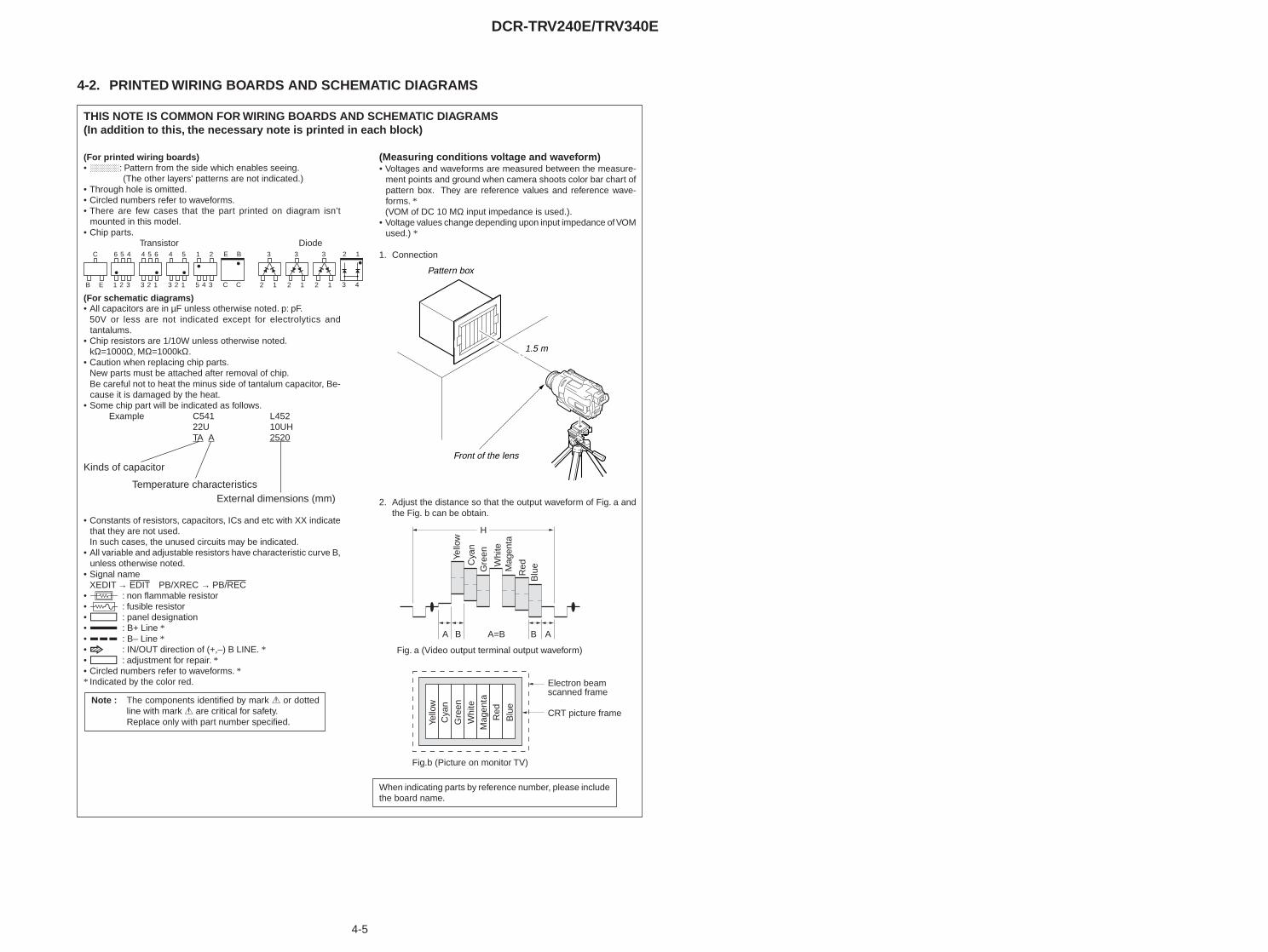
4-5
DCR-TRV240E/TRV340E
4-2. PRINTED WIRING BOARDS AND SCHEMATIC DIAGRAMS
(Measuring conditions voltage and waveform)• Voltages and waveforms are measured between the measure-
ment points and ground when camera shoots color bar chart ofpattern box. They are reference values and reference wave-forms. *(VOM of DC 10 MΩ input impedance is used.).
• Voltage values change depending upon input impedance of VOMused.) *
1. Connection
2. Adjust the distance so that the output waveform of Fig. a andthe Fig. b can be obtain.
Yello
w
A AB BA=B
Fig. a (Video output terminal output waveform)
Fig.b (Picture on monitor TV)
Electron beam scanned frame
CRT picture frame
H
Cya
nG
reen
Whi
teM
agen
ta
Red
Blu
e
Yello
wC
yan
Gre
enW
hite
Mag
enta
Red
Blu
e
THIS NOTE IS COMMON FOR WIRING BOARDS AND SCHEMATIC DIAGRAMS(In addition to this, the necessary note is printed in each block)
C
B E
56 4
21 3
54 6
23 1
4 5
23 1
1 2
45 3
3
2 1
3
2 1
3
2 1
E B
C C
2 1
3 4
Transistor Diode
Kinds of capacitor
Temperature characteristicsExternal dimensions (mm)
When indicating parts by reference number, please includethe board name.
(For printed wiring boards)• b: Pattern from the side which enables seeing.
(The other layers' patterns are not indicated.)• Through hole is omitted.• Circled numbers refer to waveforms.• There are few cases that the part printed on diagram isn’t
mounted in this model.• Chip parts.
(For schematic diagrams)• All capacitors are in µF unless otherwise noted. p: pF.
50V or less are not indicated except for electrolytics andtantalums.
• Chip resistors are 1/10W unless otherwise noted.kΩ=1000Ω, MΩ=1000kΩ.
• Caution when replacing chip parts.New parts must be attached after removal of chip.Be careful not to heat the minus side of tantalum capacitor, Be-cause it is damaged by the heat.
• Some chip part will be indicated as follows.Example C541 L452
22U 10UHTA A 2520
• Constants of resistors, capacitors, ICs and etc with XX indicatethat they are not used.In such cases, the unused circuits may be indicated.
• All variable and adjustable resistors have characteristic curve B,unless otherwise noted.
• Signal nameXEDIT → EDIT PB/XREC → PB/REC
• 2 : non flammable resistor• 1 : fusible resistor• C : panel designation• A : B+ Line *• B : B– Line *• J : IN/OUT direction of (+,–) B LINE. *• C : adjustment for repair. *• Circled numbers refer to waveforms. ** Indicated by the color red.
Note : The components identified by mark 0 or dottedline with mark 0 are critical for safety.Replace only with part number specified.
Front of the lens
1.5 m
Pattern box

DCR-TRV240E/TRV340E
4-7 4-8
CD-357 (CCD IMAGER) PRINTED WIRING BOARD
CCD IMAGERCD-357
• : Uses unleaded solder.
For printed wiring board• Refer to page 4-98 for parts location.• This board is eight-layer print board. However, the pat-
terns of layers two to seven have not been included inthe diagram.
• Chip parts
Transistor
There are a few cases that the part printed onthis diagram isn’t mounted in this model.
C
B E
63 12
54
For Schematic Diagram• Refer to page 4-91 for waveforms.
R-7
.1/P
0
R-7
.1/P
0
R-0
.3/P
0
R-0
.3/P
0
R11.6/P0
/P0
R8.
5
/P0
R1.
4
R1.
7/P
0
R-7
.5/P
0.4
R8.
5/P
0
R14
.0/P
0
R14
.8/P
0
R10.9/P0
R14.8/P0
R11.6/0
21
3
5 4
6
NO MARK:REC/PB MODE R :REC MODE P :PB MODE
82R551
LND551
GND
16PCN551
1
2
3
4
5
6
7
8
9
10
11
12
13
14
15
16
XXC554
3300R553
0.1uF
C560
IC55
1IC
X28
1BK
A-1
3
V4
1
V3
2
V2
3
V1
4
GN
D/N
C
5
GN
D
6 7
CC
D_O
UT
VD
D
8
RG
/NC
9
SU
B
10
VL
11
H1/
RG
12
H2/
H1
13
OP
EN/H
2
14
20VTA
10u
B
C552100uHL552
2SC4178-F13F14-T1Q551
10VTA
33u
B
C556
XXC557
FB5520uH
100kR557
MA111-(K8).S0D551
0.01uB
C561
XXB
C562
R558XX
XX
R56
3
XX
R56
4
0R56
5 XX
R56
7
0R56
6
0R568
0R569
1
A
CAM_15V
V4
GND
H1
V2
CCD_OUT
GND
H2
V1
V3
GND
RG
VSHT
GND
CAM-7.5
GND
its structure, handle it carefully like for the MOS IC.
SIGNAL PATH
•
3
Y/CHROMA
Precautions Upon Replacing CCD imager
PB
E
CCD IMAGER
•
6
adjustments for the camera section.
If the CCD imager has been replaced, carry out all the
54
• The CD-357 board mounted as a repair part is not equipped
CD-357 BOARD
nor exposed to strong light.
7
16
2
old one and mount it onto the new one.
REC
C
In addition, ensure that the receiver is not covered with dusts
When replacing this board, remove the CCD imager from the
G
Y
As the CCD imager may be damaged by static electricity from
F
D
with a CCD imager.CHROMA
B
VIDEO SIGNAL
IC551CCD IMAGER
BUFFER
THROUGH THEFP-161 FLEXIBLE
(PAGE 4-37)
TOVC-276 BOARD(1/25)CN1501
XX MARK:NO MOUNT
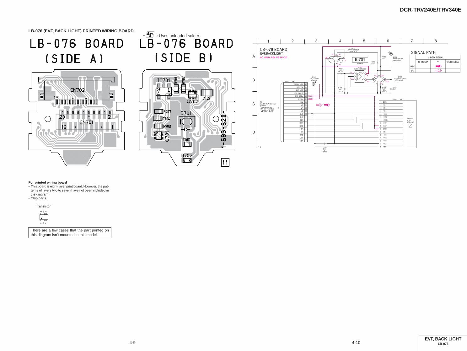
DCR-TRV240E/TRV340E
4-9 4-10
LB-076 (EVF, BACK LIGHT) PRINTED WIRING BOARD• : Uses unleaded solder.
EVF, BACK LIGHTLB-076
For printed wiring board• This board is eight-layer print board. However, the pat-
terns of layers two to seven have not been included inthe diagram.
• Chip parts
Transistor
There are a few cases that the part printed onthis diagram isn’t mounted in this model.
56 4
21 3
4.70
2.8
0
4.7
4.7
0.2
0.2
0.1
1.70.8
0.8
0.1
NO MARK:REC/PB MODENSCW100-T3D701
16PCN702
1 VDD
2 VSS
3 VST
4 VCK
5 STB
6 EN
7 DWN
8 RGT
9 HST
10 HCK2
11 HCK1
12 BLK
13 VB
14 VR
15 VG
16 COM
UP04312008S0Q702
3
5
4
6
2
1
± 0.5%33k
R701
20PCN701
1
2
3
4
5
6
7
8
9
10
11
12
13
14
15
16
17
18
19
20
NJM2125F(TE2)IC701
12
3 45
3300R703
± 0.5%22
R704
UP04601008S0Q701
3
5
4 6
2
1
± 0.5%180kR702
33kR706
2012
2.2uF
C702
6800R707
1
A
SML-310LTTD702
VCC
XTALLY_LED
EN
VR
HCK2
VB
VST
VCK
COM
HCK1
LED_DA
BLK
STB
EVF_4.75V
LED_ON/OFF
VG
EVF_VDD
HST
GND
GND
D_2.8V
PB
4
VIDEO SIGNAL
2
LED DRIVE
6
EVF,BACKLIGHT
C
Y
5
BACKLIGHT
16
D
CHROMA
B
REC
8
Y/CHROMA
3 7
SIGNAL PATH
(PAGE 4-62)
THROUGH THEFP-407 FLEXIBLE
TOVC-276 BOARD(13/25)CN7001
IC701BUFFER
LED SWITCH
(TALLY)
LB-076 BOARD
B/WEVF UNIT
LCD903
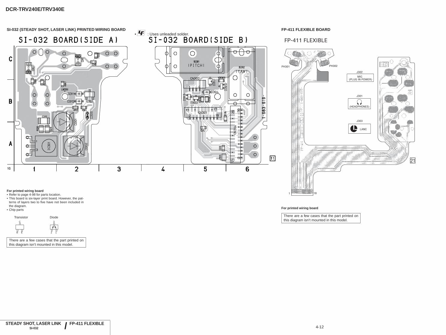
DCR-TRV240E/TRV340E
4-12STEADY SHOT, LASER LINK
SI-032
SI-032 (STEADY SHOT, LASER LINK) PRINTED WIRING BOARD• : Uses unleaded solder.
For printed wiring board• Refer to page 4-98 for parts location.• This board is six-layer print board. However, the pat-
terns of layers two to five have not been included inthe diagram.
• Chip parts
Transistor Diode
There are a few cases that the part printed onthis diagram isn’t mounted in this model.
FP-411 FLEXIBLE
FP-411 FLEXIBLE BOARD
/
For printed wiring board
There are a few cases that the part printed onthis diagram isn’t mounted in this model.C
B E
3
2 1
FP-411 FLEXIBLE
21
J302
J301
PH302PH301
MIC(PLUG IN POWER)
(HEADPHONES)
J303
LANC
1 18
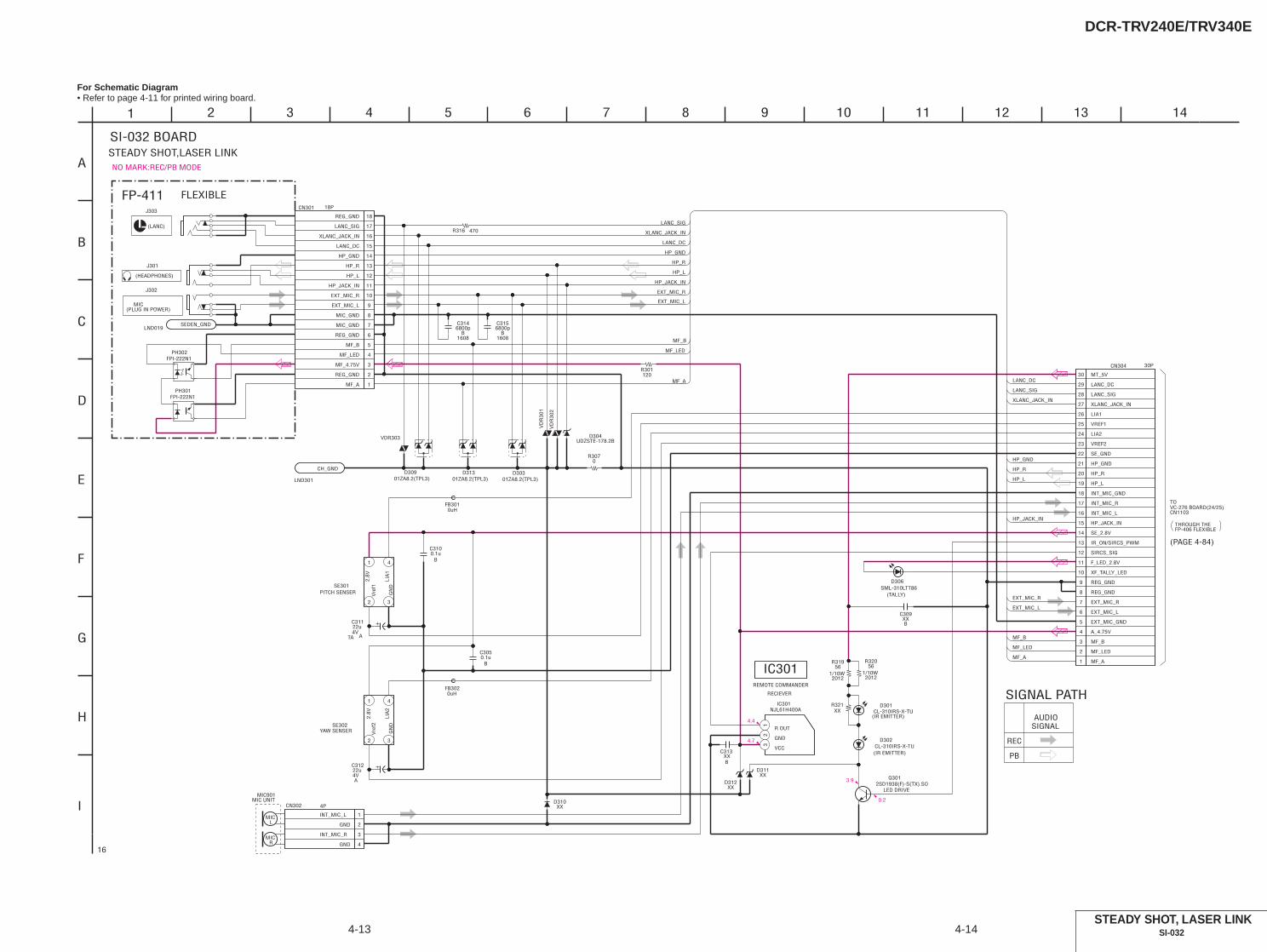
DCR-TRV240E/TRV340E
4-13
For Schematic Diagram• Refer to page 4-11 for printed wiring board.
4-14STEADY SHOT, LASER LINK
SI-032
4.4
4.7
3.9
0.2
NO MARK:REC/PB MODE
LND301
CH_GND
UDZSTE-178.2BD304
120R301
0R307
01ZA8.2(TPL3)D303
2SD1938(F)-S(TX).SOQ301
VD
R30
2
SE302
1
2 3
4
VD
R30
1
CL-310IRS-X-TUD302
0.1uB
C305
SE301
1
2 3
4
SML-310LTT86D306
0.1uB
C310
4V22u
TA A
C311
4V22u
A
C312
FB3010uH
FB3020uH
30PCN304
1
2
3
4
5
6
7
8
9
10
11
12
13
14
15
16
17
18
19
20
21
22
23
24
25
26
27
28
29
30
18PCN301
1
2
3
4
5
6
7
8
9
10
11
12
13
14
15
16
17
18
470R316
01ZA8.2(TPL3)D309
VDR303
NJL61H400AIC301
1
R OUT
2
GND
3
VCC
20121/10W
56R319
20121/10W
56R320
XXD310
CN302 4P
1
2
3
4
XXB
C309
D311XX
XXD312
CL-310IRS-X-TUD301
XXR321
XXB
C313
1608
6800pB
C314
1608
6800pB
C315
01ZA8.2(TPL3)D313
1
A
LND019SEDEN_GND
J303
MF_LED
MF_A
MF_B
MF_LED
HP_GND
HP_R
HP_JACK_IN
HP_L
EXT_MIC_L
EXT_MIC_R
LANC_SIG
XLANC_JACK_IN
LANC_DC
HP_GND
LANC_SIG
XLANC_JACK_IN
LANC_DC
HP_L
EXT_MIC_L
EXT_MIC_R
MF_A
MF_B
HP_R
HP_JACK_IN
MF_A
HP_GND
MF_B
MF_4.75V
MF_LED
REG_GND
HP_R
HP_JACK_IN
HP_L
EXT_MIC_L
EXT_MIC_R
MIC_GND
LIA2
VREF2
EXT_MIC_GND
SE_GND
VREF1
MT_5V
SE_2.8V
INT_MIC_L
LIA1
(TALLY)
MIC_GND
REG_GND
2.8V
2.8V
Vre
f2V
ref1
LIA
1LI
A2
LANC_DC
XLANC_JACK_IN
LANC_SIG
REG_GND
HP_R
A_4.75V
LANC_DC
REG_GND
HP_L
REG_GND
EXT_MIC_L
INT_MIC_GND
XF_TALLY_LED
HP_JACK_IN
LANC_SIG
SIRCS_SIG
INT_MIC_R
HP_GND
MF_A
EXT_MIC_R
IR_ON/SIRCS_PWM
F_LED_2.8V
XLANC_JACK_IN
MF_B
MF_LED
INT_MIC_L
INT_MIC_R
GND
GND
F
3 6
I
E
5 742
SI-032 BOARD
9
D
C
1210
STEADY SHOT,LASER LINK
16
H
G
B
8 11
J302
MIC(PLUG IN POWER)
FP-411 FLEXIBLE
PH302FPI-222N1
FPI-222N1PH301
J301
(HEADPHONES)
(LANC)
GN
D
PITCH SENSER
GN
D
YAW SENSER
RECIEVER
REMOTE COMMANDER
IC301
(IR EMITTER)
LED DRIVE
(IR EMITTER)
(PAGE 4-84)
TOVC-276 BOARD(24/25)CN1103
THROUGH THEFP-406 FLEXIBLE
SIGNAL
SIGNAL PATH
PB
REC
AUDIO
13 14
MIC901
MIC R
MIC L
MIC UNIT
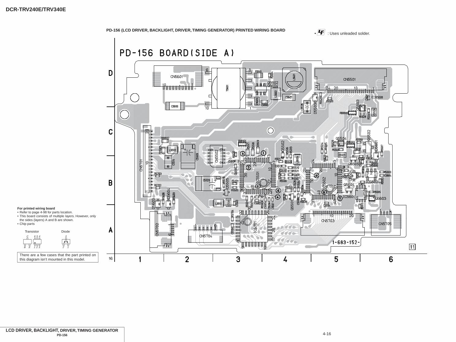
DCR-TRV240E/TRV340E
4-16
PD-156 (LCD DRIVER, BACKLIGHT, DRIVER, TIMING GENERATOR) PRINTED WIRING BOARD• : Uses unleaded solder.
LCD DRIVER, BACKLIGHT, DRIVER, TIMING GENERATORPD-156
For printed wiring board• Refer to page 4-98 for parts location.• This board consists of multiple layers. However, only
the sides (layers) A and B are shown.• Chip parts
Transistor Diode
There are a few cases that the part printed onthis diagram isn’t mounted in this model.
C
B E
56 4
21 3
3
2 1

DCR-TRV240E/TRV340E
4-17
• : Uses unleaded solder.
LCD DRIVER, BACKLIGHT, DRIVER, TIMING GENERATORPD-156
FP-412 FLEXIBLE
16
S601(PANEL REVERSE)
22
FP-412 FLEXIBLE BOARD
For printed wiring board
There are a few cases that the part printed onthis diagram isn’t mounted in this model.
/ FP-412 FLEXIBLE
Ver 1.2 2002. 06

DCR-TRV240E/TRV340E
4-19 4-20
Note : The components identified by mark 0 or dottedline with mark 0 are critical for safety.Replace only with part number specified.
For Schematic Diagram• Refer to page 4-15 for printed wiring board.
LCD DRIVER, BACKLIGHTPD-156 (1/2)
(DCR-TRV240E:AEP,UK/TRV340E:AEP,UK only)
3.93.9
0.20.2
0.4
1.4
2.8
2.8
2.8
1.4
2.8
0
1.4
0
2.8
1.5
1.5
1.5
1.5
1.5
1.5
1.5
1.5
1.5
1.5
1.5
1.5
1.5
1.5
1.6
2.0
3.0
2.8
2.8
2.0 0
1.5
1.5
1.5
1.5
1.5
1.5
NO MARK:REC/PB MODE
LED
D5602XX
R5609XX
MA111-(K8).S0D5601
12
L5601
IC5601TC7W53FU(TE12R)
1 COM
2 INH
3 VEE
4 GND 5A
6CH1
7CH0
8VCC
R56
0312
k
0.015uB
C5603
1/10W1800
R5601
XXR5604
IC5602TA75S393F-TE85R
12
345
R5605XX
0.1uB
C5605
DAC
R5608XX
10PCN5601
1 LED_GND
2 LED
3 BL_LOW
4 N.C.
5 N.C.
6 N.C.
7 N.C.
8 N.C.
9 N.C.
10 BL_HIGH
D5604XX
B
C56040.1u
BL_ON
R5602100k
XXD5603LD5605
A
C5606
470R5607
22kR5606
Q5603XX 3
5
4
6
2
1
4.7uB
C5607
XXC5608
10kR5613
XXR5614
RN1104F(TPL3)Q5601
10kR5612
XXD5605
Q5602XX
6
1
5
4
3
2Q5604
CPH5504-TL-E
1
5
4
2
3
4.7uHL5602
T5601
1
2
3
4
5
6
10
PANEL_B
PANEL_13.3V
6PCN5704
1
2
3
4
5
6
CN5703 20P
1
2
3
4
5
6
7
8
9
10
11
12
13
14
15
16
17
18
19
20
R5702XX
XVD
680kR5704
PANEL_2.8V
XVC_SCK
XCS_PANEL
CN5702 6P
1
2
3
4
5
6
R5703XX
REG_GND
CN5701 20P
1
2
3
4
5
6
7
8
9
10
11
12
13
14
15
16
17
18
19
20
SYNC
PANEL_4.75V
0.1uB
C5701
PANEL_G
BU9735K-E2IC5701
1 OSC1
2 OSC2
3 VSS
4 VC
5 VLCD
6 VDD
7 SCK
8 SD
9
XC
S
10
C/X
D
11
CO
M1
12
CO
M2
13
CO
M3
14
CO
M4
15
SEG
1
16
SEG
2
17SEG3
18SEG4
19SEG5
20SEG6
21SEG7
22SEG8
23SEG9
24SEG10
25
SEG
11
26
SEG
12
27
SEG
13
28
SEG
14
29
SEG
15
30
SEG
16
31
SEG
17
32
SEG
18
XVC_SO
XSYS_RST
PANEL_-15.3V
HOLD
CN5705 4p
1
2
3
4
PANEL_R
LND007
SE_GND
S601
DETIN
1
A
SEG4
XCS
SCK
SEG
16
COM4
SEG7
SEG2
SEG8
SEG7
CO
M3
SEG16
SEG
11
SEG15
SEG5SEG11
SEG10
SEG1
C/XD
SEG14
SCK
SEG4
C/XD
SEG6
SEG9
CO
M4
SEG10
SEG
12
CO
M1
CO
M2
COM1
SEG
1
SO
SEG
13
SEG
14
COM2
SEG
2
SOSEG13
COM3
SEG12
SEG3
SEG
15
SEG3
SEG9
SEG6
SEG8
SEG5
XCS
100uH
VCC
SL12pF
ND901BACK LIGHT
PANEL_R
N.C.
XCS_LCD_DA
PANEL_XVD
SEG5
XSYS_RST
SEG12
COM1
OSD_SO
PANEL_4.75V
PANEL_G
LCD_COM/XDATA
PANEL_REV
VC_SO
SE_GND
SEG16
SEG7
SEG10
BL_GND
DISP_LCD_VDD
COM3
BL_CONT
XPANEL-REV
SEG6
BL_GND
C-SYNC/XHD
SEG13
PANEL_REV
SEG8
BL_VDD
PANEL_2.8V
SEG11
N.C.
SEG2
PANEL_HOLD
PANEL_13.3V
GND
COM2
DISP_BL
BL_VDD
BL_GND
COM4
SEG14
PANEL_B
SEG15
GND
PANEL_-15.3V
XOSD_SCK
XVC_SCK
REG_GND
SEG3
SEG1
BL_REG
SEG9
SEG4
XCS_LCD_DRIVER
(PANEL REVERSE)
FP-412FLEXIBLE
LCD DRIVER,BACK LIGHT(LCD/BL BLOCK)PD-156 BOARD(1/2)
16
1 TO(2/2)
OSC
INVERTERTRANSFORMER
CURRENT DETECT
IC5602
BL SWITCH
TO(2/2)2
IC5601BACKLIGHT
BRIGHT SWITCH
BACKLIGHT
D902
FP-414FLEXIBLE
LCD902CHARACTER DISPLAY UNIT
CHARACTORDISPLAY DRIVER
IC5701TOCONTROLSWITCH BLOCK(CF-2500)CN005THROUGH THECP-076 HARNESS
(PAGE 4-31)
(PAGE 4-84)
THROUGH THEVP-076 HARNESS
TOVC-276 BOARD(24/25)CN1106
FP-414 FLEXIBLE is replaced as a block.So that this PRINTED WIRING BOARD is omitted.
2
G
5
E
133
F
4
J
C
9 12
D
I
B
8 11 14
H
76 10
ANALOG IN
DV IN
SIGNAL PATH
CHROMA Y/CHROMAY
VIDEO SIGNAL
XX MARK:NO MOUNT
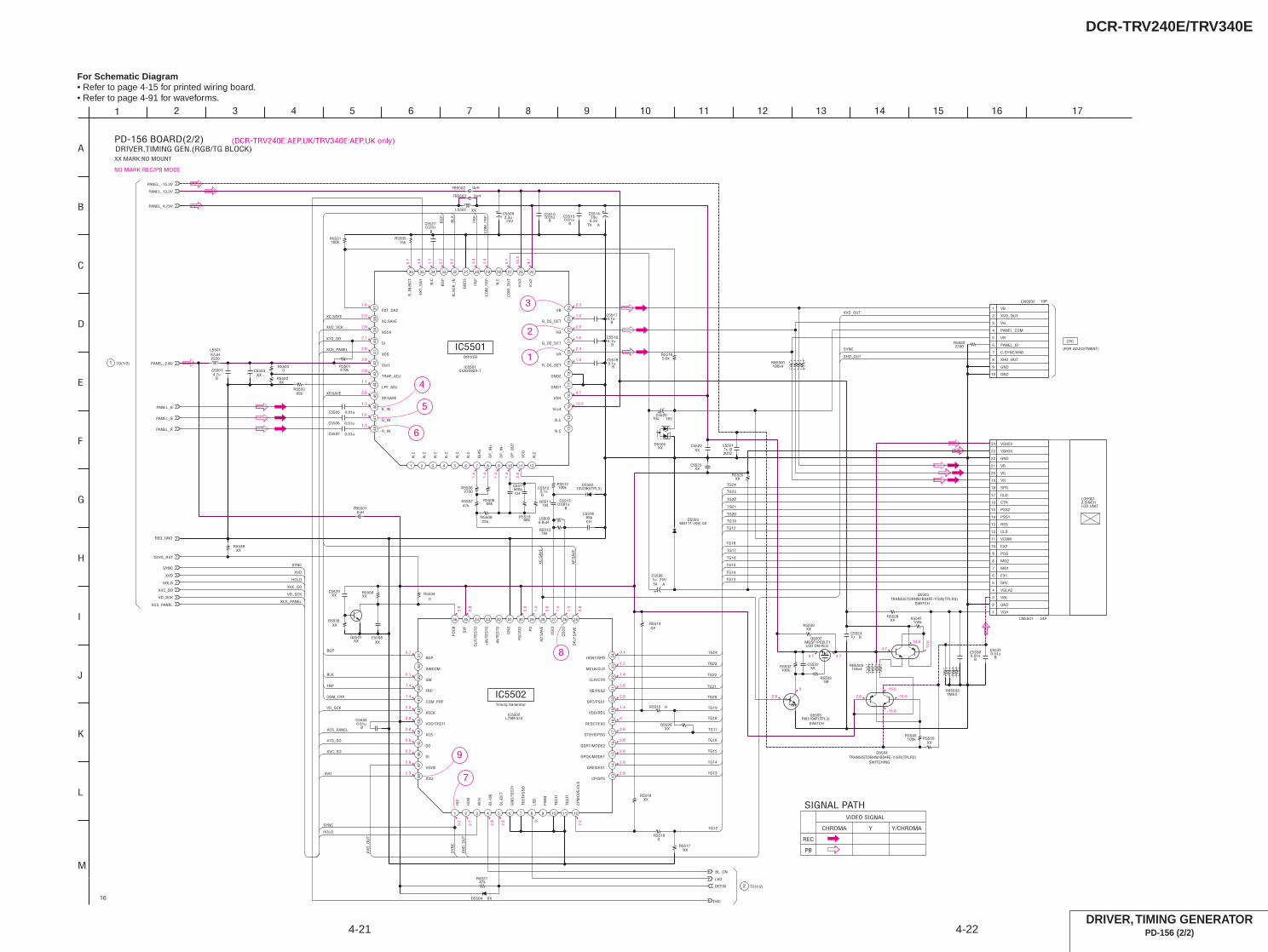
DCR-TRV240E/TRV340E
4-21 4-22
For Schematic Diagram• Refer to page 4-15 for printed wiring board.• Refer to page 4-91 for waveforms.
DRIVER, TIMING GENERATORPD-156 (2/2)
(DCR-TRV240E:AEP,UK/TRV340E:AEP,UK only)
4
5
6
1
2
3
9
7
8
0.7
1.5
1.1
2.7
0.2
4.7
1.4
1.4
0.7
13.3
1.6
2.9
2.8
2.7
2.8
2.8
2.8
1.1
2.8
1.3
1.6
1.3
2.3
1.6
2.3
1.6
2.3
1.6
4.7
13.3
1.4
1.4
1.4
1.4
2.8
2.8
2.8
2.8
1.4
2.8
1.4
1.3
2.8
2.7
2.3
0.1
1.4
1.4
2.5
2.8
2.8
2.8
0.2
2.8
0.2
2.7
2.8
2.8 0
2.5
0.1
1.2
1.4
2.8
2.3
1.4
0
2.8
2.8
2.8
2.8
2.8
4.7
13.8
13.6
2.8
-15.6
-15.0
-15.6
4.74.7
2.8
0
NO MARK:REC/PB MODE
FB5502 0uH
XXR5502
R5504XX
D55021SV290(TPL3)
1u BC5521
XVC_SO
R5526XX
0R5534
1MR5511
470kR5501
82kR5503
100kR5540
15kR5505
XXD5505
0.01uB
C5513
0.01uB
C5530
68kR5510
XXR5529
XCS_PANEL
R552147k
10uC5514
TA6.3V
A0.01u
B
C5527
PANEL_4.75V
0.1uB
C5517
REG_GND
R55190
RB5502
R5539XX
XVD
RN1104F(TPL3)Q5505IC5502
LZ9FF474
1
HD
I
2
HD
B
3
W/H
4
BL-
ON
5
BL-
DET
6
GN
D/T
ESTI
7
TES
TI/G
ND
8
LED
9
PW
M
10
TES
TI
11
TES
TI
12
CP
MO
DE/
CLS
13CP/SPS
14GRES/EX1
15GPCK/MODE1
16GSRT/MODE2
17STBYB/PSG
18RESET/EX2
21OE/PSS2
19VDD/RES
20SRT/PSS1
22CLR/CTR
23MCLK/CLD
24HCNT/SPD
25
DR
.P.S
AV
E
26
OS
CO
27
OS
CI
28
XC
.SA
VE
29
PD
30
PS
/VD
D
31
GN
D
32
-IN
/TES
TO
33
+IN
/TES
TO
34
OU
T/TE
STO
35
SY
F
36
PO
CB
37 BGP
38 SWCOM
39 SW
40 FRP
41 COM_FRP
42 XSCK
45 SO
44 XCS
43 VDD/TESTI
46 SI
47 VSYB
48 XVD
1u BC5524
HOLD
BL_ON
DETIN
0.1uB
C5519
XXR5520
100kR5541
PANEL_2.8V
4.7uB
C5501
MGSF1P02LT1Q5502
0.1uB
C5518
PANEL_B
C5529XX
FB55010uH
16V10uC5520
100kR5512
XXC5523
XXR5528
0.01uC5507
PANEL_13.3V
PANEL_G
0.1uB
C5512
C5532XX
0.001uB
C5515
0.01uC5505
L550147uH
24PCN5501
1
2
3
4
5
6
7
8
9
10
11
12
13
14
15
16
17
18
19
20
21
22
23
24
0R5523
XXR5517
0.01uC5506
MA111-(K8).S0D5503
0R5515
47kR5507
C55093.3u25V
XXQ5501
XXR5530
XXR5514
PANEL_-15.3V
180kR5531
Q5504TRANSISTORHN1B04FE-Y/GR(TPLR3)
PANEL_R
22kR5509
560pCH
C5511
0.01uB
C5531
XXC5522
XXC5508
TA
C55281u 25V
A
LED
2700R5506
VD_SCK
6.8uHL5503
D5504 XX
L5502 XX
5.6kR5516
0.01uB
C5510
1MR5533
68kR5508
DAC
XXC5503
FB5503 0uH
XSYS_RST
RB550310kx4
68pCH
C5516
XXR5518
100kR5532
0.01uB
C5504
Q5503TRANSISTORHN1B04FE-Y/GR(TPLR3)
10PCN5502
1 VB
2 XVD_OUT
3 VG
4 PANEL_COM
5 VR
6 PANEL_ID
7 C-SYNC/XHD
8 XHD_OUT
9 GND
10 GND
1MR5513
SYNC
XXR5525
2200R5522
RB5501100x4
1
A
IC5501CXA3592R-T
1
N.C
2
N.C
3
N.C
4
N.C
5
N.C
6N
.C7
BIA
S
8
OP
_IN
+
9
OP
_IN
-
10
OP
_OU
T
11
VC
O
12
N.C
13N.C
14N.C
15Vcc4
16VSH
17GND1
18GND2
21G_DC_DET
19R_DC_DET
20VR
22VG
23B_DC_DET
24VB
25
Vcc
2
26
Vcc
3
27
CO
M_O
UT
28
N.C
29
CO
M_F
RP
30
FRP
31
GN
D3
32
BLA
CK
_IN
33
BG
P
34
N.C
35
EXT_
DA
1
36
R_I
NJE
CT
37 EXT_DA2
38 XC.SAVE
39 XSCK
40 SI
41 XCS
42 Vcc1
45 XP.SAVE
44 LPF_ADJ
43 TRAP_ADJ46 B_IN
47 G_IN
48 R_IN
TG14
TG16
TG15
TG13
XCS_PANEL
XVC_SCK
TG18
TG16
TG15
TG14
TG13
CO
M_F
RP
FRP
BG
P
XP.SAVE
BGP
VD_SCK
XCS_PANEL
XVC_SO
XVD
SYNC
XVC_SO
XCS_PANEL
XVD
HOLD
FRP
BLK
XP.
SA
VE
XC.SAVE
TG18
TG20
TG21
TG22
TG24
HOLD
COM_FRP
XTG_SO
TG24
BLK
TG23
TG22
TG20
TG21
TG19
TG17
TG17
VD_SCK
TG12
TG12
TG19
XC
.SA
VE
TG23
XTG_SO
XH
D_O
UT
XV
D_O
UT
SYNC
SY
NC
XVD_OUT
SYNC
XHD_OUT
CLS
VGLAC
CLD
PSS1
PSS2
EX1
MO2
RES
EX2
VB
VG
VR
VGL
SPC
VSH5V
MO1
GND
VSH3V
GND
VCOM
CTR
VGH
PSG
SPD
2520
2012
1MX4
DRIVER
IC5501
IC5502Timing Generator
SWITCH
SWITCHING
SWITCH
LCD ON REG
CPC
(FOR ADJUSTMENT)
2.5INCHLCD901
LCD UNIT
TO(1/2)1
CHROMA Y Y/CHROMA
PB
REC
VIDEO SIGNAL
SIGNAL PATH
TO(1/2)2
XX MARK:NO MOUNT
PD-156 BOARD(2/2)DRIVER,TIMING GEN.(RGB/TG BLOCK)
16
2
G
K
5
E
M
17133
F
4
J
L
16
C
9 12
D
15
I
B
8 11 14
H
76 10
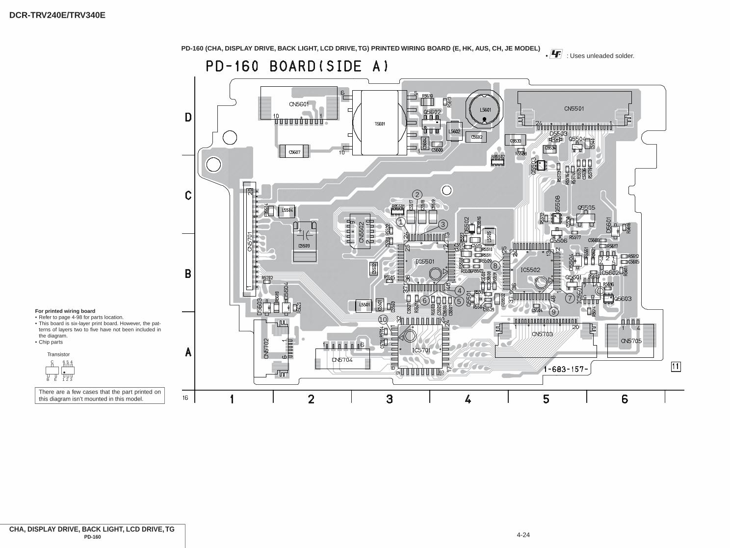
DCR-TRV240E/TRV340E
PD-160 (CHA, DISPLAY DRIVE, BACK LIGHT, LCD DRIVE, TG) PRINTED WIRING BOARD (E, HK, AUS, CH, JE MODEL)
CHA, DISPLAY DRIVE, BACK LIGHT, LCD DRIVE, TGPD-160 4-24
• : Uses unleaded solder.
1 3
7
9
4
56
10
8
2
For printed wiring board• Refer to page 4-98 for parts location.• This board is six-layer print board. However, the pat-
terns of layers two to five have not been included inthe diagram.
• Chip parts
Transistor
There are a few cases that the part printed onthis diagram isn’t mounted in this model.
C
B E
56 4
21 3
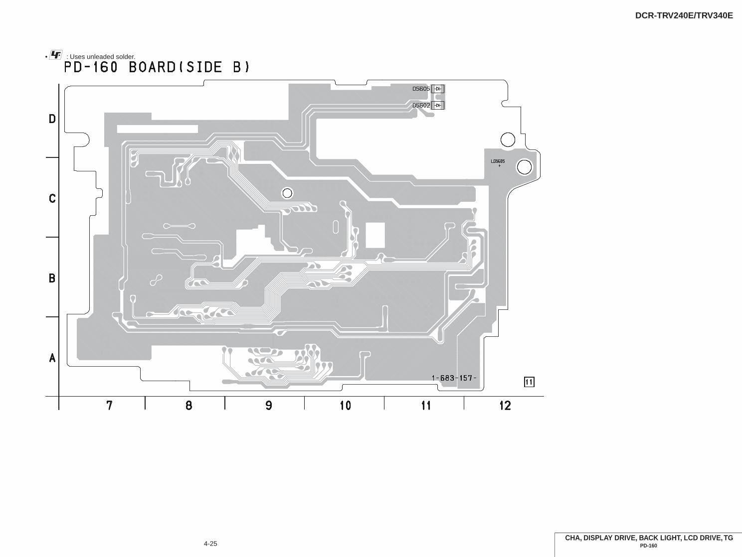
DCR-TRV240E/TRV340E
4-25CHA, DISPLAY DRIVE, BACK LIGHT, LCD DRIVE, TG
PD-160
• : Uses unleaded solder.

DCR-TRV240E/TRV340E
4-27 4-28CHA, DISPLAY DRIVE, BACK LIGHT
PD-160 (1/2)
For Schematic Diagram• Refer to page 4-23 for printed wiring board.• Refer to page 4-92 for waveform.
Note : The components identified by mark 0 or dottedline with mark 0 are critical for safety.Replace only with part number specified.
5.1 5.1
-0.6
-0.6
0.4
1.7
2.8
2.8
04.7
0
4.7
4.7
1.8 2.8
1.8
2.8
0
0
0
2.8
1.5
1.5
1.5
1.5
1.5
1.5
1.5
2.0
3.0
3.0
3.0
3.0
0.7
2.9 0
1.5
1.5
1.5
1.5
1.5
1.5
1.5
1.5
1.5
1.5
1.5
1.5
1.5
1.5
10
NO MARK:REC/PB MODE
R5620XX
R5619XX
R5616XX
470R5618
1/10W1800
R5610
R5611180k
L5601100uH
MA111-(K8).S0D5601
12pC5607
0.015uB
C5604
0.1uB
C5606
LED
IC5601TC7W53FU(TE12R)
1 COM
2 INH
3 VEE
4 GND 5A
6CH1
7CH0
8VCC
B
C56050.1u
DETIN
R561222k
XXR5613
10PCN5601
1 LED_GND
2 LED
3 BL_LOW
4 N.C.
5 N.C.
6 N.C.
7 N.C.
8 N.C.
9 N.C.
10 BL_HIGH
22kR5617
IC5602TA75S393F-TE85R
12
345
D5603XX
LND705
CH_GND
D5604XX
12
T5601
1
2
3
4
5
6
10
DAC
BL_ON
10kR5614
Q5603XX
3
5
4
6
2
1
4.7uB
C5602
XXC5608
D5602XX
XXR5621
DTC144EHT2LQ5601
10kR5609
XXD5605
XXQ5604
1
5
4
2
3
TPC6C01(TE85R)Q5602
6
1
5
4
3
2
4.7uHL5602
0.1uB
C5701
6PCN5704
1
2
3
4
5
6
CN5702 6P
1
2
3
4
5
6
CN5705 4P
1
2
3
4
XVD
20PCN5701
1
2
3
4
5
6
7
8
9
10
11
12
13
14
15
16
17
18
19
20
XVC_SO
XSYS_RST
XXR5702
680kR5704
PANEL_13.3V
CN5703 20P
1
2
3
4
5
6
7
8
9
10
11
12
13
14
15
16
17
18
19
20
XCS_PANEL
REG_GND
PANEL_R
BU9735K-E2IC5701
1 OSC1
2 OSC2
3 VSS
4 VC
5 VLCD
6 VDD
7 SCK
8 SD
9
XC
S
10
C/X
D
11
CO
M1
12
CO
M2
13
CO
M3
14
CO
M4
15
SEG
1
16
SEG
2
17SEG3
18SEG4
19SEG5
20SEG6
21SEG7
22SEG8
23SEG9
24SEG10
25
SEG
11
26
SEG
12
27
SEG
13
28
SEG
14
29
SEG
15
30
SEG
16
31
SEG
17
32
SEG
18
PANEL_B
SYNC
PANEL_G
XVC_SCK
1
A
S601
LND007
SE_GND
PANEL_2.8V
SEG13
SEG2
COM4
SEG10
SEG11
SEG5
SEG3
SEG
1
SEG8
SEG6
XCS
SEG9
SEG5
SEG8
XCS
SEG
13
SO
SCK
C/XD
SEG
16
SO
SEG7
CO
M3
SEG3
SEG15
CO
M1
SEG4
SEG
2
SEG12
COM3
SEG
12
SEG
11
SEG9
SEG
15
SEG1
COM2
SEG16
SEG
14
SEG7
CO
M4
SEG6
SCK
C/XD
SEG10
CO
M2
COM1
SEG14
SEG4
VCC
SL
FP-414 FLEXIBLE is replaced as a block.So that this PRINTED WIRING BOARD is omitted.
BACK LIGHTND901
INVERTERTRANSFORMER
SWITCH
IC5602
BACK LIGHTBRIGHT SWITCH
OSC
IC5601
CURRENT DETECT
2 TO(2/2)
PANEL_2.8V
XSYS_RST
GND
SEG2
SEG12
SEG15
PANEL_HOLD
REG_GND
BL_GND
COM1
PANEL_XVD
XPANEL_REV
XOSD_SCK
PANEL_13.3V
PANEL_4.75V
DISP_BL
SEG7
SEG16
PANEL_REV
N.C.
SEG10
BL_VDD
SEG9
N.C.
SEG13
PANEL_REV
GND
BL_GND
SEG11
OSD_SO
COM4
SEG14
BL_GND
VC_SO
PANEL_-15.3V
BL_REG
LCD_COM/XDATA
SEG5
SEG8
COM2
XCS_LCD_DA
XVC_SCK
PANEL_R
XCS_LCD_DRIVER
SEG3
BL_CONT
BL_VDD
COM3
DISP_LCD_VDD
SEG1
PANEL_G
C-SYNC/XHD
PANEL_B
SEG6
SE_GND
SEG4
J
CHA.DISPLAY DRIVE,BACK LIGHT(LCD/BL BLOCK)
108
B
PD-160 BOARD(1/2)
D
52 4 12
E
113
16
G
I
1396 7
F
C
H
1 TO(2/2)
CHARACTORDISPLAY DRIVER
IC5701
D902
FLEXIBLE
LCD902CHARACTER DISPLAY UNIT
FP-414
BACKLIGHT
(PANEL REVERSE)
FLEXIBLEFP-412
THROUGH THEVP-076 HARNESS
TOVC-276 BOARD(24/25)CN1106
(PAGE 4-84)
THROUGH THECP-076 HARNESS
TOCONTROLSWITCH BLOCK(CF-2500)CN005
(PAGE 4-31)
VIDEO SIGNAL
ANALOG IN
Y
DV IN
Y/CHROMA
SIGNAL PATH
CHROMA
XX MARK:NO MOUNT

DCR-TRV240E/TRV340E
4-29LCD DRIVE, TG
PD-160 (2/2)4-30
For Schematic Diagram• Refer to page 4-23 for printed wiring board.• Refer to page 4-92 for waveforms.
1.2
2.8
2.5
2.0
2.7
2.8
2.8
1.4
2.8
1.8
1.8
1.8
0.7
1.8
2.7
0 2.8
1.4
1.4
2.8
7.1
1.7
13.4
7.1
1.7
7.1
1.7
7.1
1.7
13.42.
8
0.5
0.5
2.8
0.5
1.4
1.4
1.4
1.4
2.4
6.8
6
5
4
1
2
3
13.4 13.4
0
0
2.8
7.6 13.4
7.0 7.6
7.0
7.0
6.4
7.0
6.4
13.4
2.7
2.8
0
1.4
1.4
2.5
2.8
2.7
2.2
2.0
0
2.7
0 0.5
0.5
2.8
0.5
2.8
1.4
2.8
1.4
1.4
2.8
0
1.4
2.5
0
0.2
2.8
0
1.4
1.4
0
2.8
2.6
0.3
2.8
2.9 0
8
9
7
NO MARK:REC/PB MODE
1.6
1.0
0.01uC5505
1SV290(TPL3)D5502
22kR5509
PANEL_G
XXR5505
C5509
25V3.3u
100kR5512
47kR5507
PANEL_13.3V
27uHL5505
XVD
0.01uB
C5510
R5504XX
20121u BC5519
0.01uB
C5504
IC5501CXA3289AR-T4
1
XS
H.S
AV
E
2
SH
_R
3
SH
_G
4
SH
_B
5
SH
_A
6G
ND
/N.C
.7
BIA
S
8
OP
_IN
+
9
OP
_IN
-
10
OP
_OU
T
11
VC
O
12
CO
M_D
C
13COM_IN
14COM_OUT
15Vcc3
16VREF
17GND1
18GND2/N.C.
21G_DC_DET
19R_DC_DET
20VR
22VG
23B_DC_DET
24VB
25
Vcc
2
26
P_D
C_D
ET
27
VP
28
XV
P.S
AV
E
29
PFR
P
30
FRP
31
PR
G
32
BLA
CK
_IN
33
BG
P
34
N.C
.
35
EXT_
DA
36
N.C
./R
_IN
JEC
T
37 N.C./C_BG
38 XC.SAVE
39 XSCK
40 SI
41 XCS
42 Vcc1
45 XP.SAVE
44 LPF_ADJ
43 TRAP_ADJ46 B_IN
47 G_IN
48 R_IN
L550147uH
XXC5508
XCS_PANEL
XXC5503
20121u BC5518
XVC_SCK
XVC_SO
LED
100kR5503
68kR5510
0.001uB
C5515
DETIN
REG_GND
PANEL_R
470kR5501
PANEL_2.8V
68kR5508
2700
R55
06
82pC5516
20121u BC5517
1MR5511
0.01uC5506
560p
C55
11
SYNC
0.1uB
C5512
PANEL_B
DAC
0.01uC5507
CXD3512R-T4IC5502
1
HD
2
HD
O
3
XW
RT
4
BL_
ON
5
DET
IN
6
GN
D
7
TST0
8
LED
9
PW
M
10
TES
T
11
TES
T
12
TES
T
13TSTEN
14POFF
15RGT
16HCK1
17HCK2
18HST
21DWN
19VDD
20WIDE
22EN
23VCK
24VST
25
XS
TBY
26
OS
CO
27
OS
CI
28
XC
.SA
VE
29
RP
D
30
TES
T
31
VS
S
32
SH
A
33
SH
B
34
SH
G
35
SH
R
36
XC
LR
37 XCLP
38 PRG
39 SBLK
40 FRP
41 PFRP
42 XSCK
45 SO
44 XCS
43 VDD
46 SI
47 VDO
48 XVD
R555147k
10PCN5502
1 VB
2 XVD_OUT
3 VG
4 PSIG
5 VR
6 MAKER_CHECK
7 XHD
8 XHD_OUT
9 GND
10 GND
22kR5522
XXC5527
C5529XX
R5560XX
XXQ5501
FB55020uH
L5504XX
20121u BC5532
3216
4.7uB
C5533
RD3.3UM-T1BD5503
2012
1uB
C5534
10kR5572
10kR5573
2SA1774HT2LQ5504
820kR5574
68kR5575
1MR5576
0.1uB
C5536
NDS356APQ5505
DTC144EHT2LQ5506
470kR5577
R5579150k
0.1uB
C5540
1608
24PCN5501
1 TEST2
2 RGT
3 B
4 R
5 G
6 PSIG
7 HCK1
8 HCK2
9 CRext
10 SOUT
11 REF
12 HST
13 WIDE
14 CS
15 VVSSG
16 VDOG
17 VSS
18 VDD
19 DWN
20 EN
21 VCK
22 VST
23 COM
24 TEST1
UP04601008S0Q5503
3
5
4 6
2
1
UP04601008S0Q5508
3
5
46
2
1
R5588XX
BL_ON
XSYS_RST
0R5590
FB55040uH
RB5501
RB5502
4.7uB
C5501
D5504XX
XXR5591
0.01uB
C5538
1
A
XCS_PANEL VR
VB
VGXVC_SCK
PFR
P
FRP
BG
P
XP.SAVE
BGP
XVC_SCK
XCS_PANEL
XVC_SO
XVD
SYNC
XVC_SO
XCS_PANEL
XVD
FRP
BLK
XP.
SA
VE
XC.SAVE
XTG_SO
PFRP
XHD_OUT
SYNC
XTG_SO
BLK
XVC_SCK
XC
.SA
VE
PR
G
PRG
VP
SH
4
SH
3
SH
2
SH
1
SH
2
SH
3
SH
4
SH
1
VB
VP
TG24
TG23
TG22
TG21
TG20
TG18
TG16
TG15
TG14
TG24
TG23
TG22
TG21
TG20
TG18
TG17
TG16
TG15
VRV
G
TG14
TG17
VB
VG
VR
XH
D_O
UT
XV
D_O
UT
SYNC
SY
NC
XVD_OUT
DRIVER
Timing Generator
1608
2520
100X4
100KX4
SWITCH
SWITCH
LEVEL SHIFT
LCD B+ REG
LCD SWITCH
16
2
E
L
B
J
I
G
4 156
D
7 1312
H
9 14
F
10 113 8
C
5
K
2.5INCHLCD901
CPC (FOR CHECK)
IC5501
IC5502
1 TO(1/2)
2 TO(1/2)
PD-160 BOARD(2/2)LCD DRIVE,TG(RGB/TG BLOCK)
SIGNAL PATH
ANALOG IN
DV IN
VIDEO SIGNAL
Y/CHROMAYCHROMA
M
XX MARK:NO MOUNT
No Mt
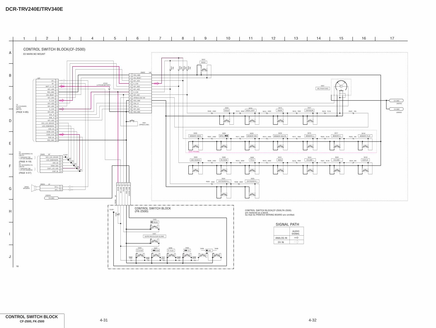
DCR-TRV240E/TRV340E
4-32CONTROL SWITCH BLOCK
CF-2500, FK-2500 4-31
(DCR-TRV340E)
R024
BT001
R014
R015
R022
R026
S018
S006
S010
LND003
CH GND
5PC
N00
6
12345
R006
S003
R00
3
S028
S016
CL001
S024
R017
R02
7
R010
S019
R007
S027
CL005
S013
CL002
S029
R021
S004
LND002
CH GND
S009
R023
14PCN002
1
2
3
4
5
6
7
8
9
10
11
12
13
14
S005
R012
S023
S015
R013
R008
S025R
004
R018
R00
2
S012
S026
2PCN004
1SP(+)
2SP(-)
R011
R016
R020
S001
CL006
R025
R019
6PCN005
1
2
3
4
5
6
CL004
CL003
S007
S022
S017
LND004
CH GND
3900R408
S401
S409
10k
R40
9
S408
S405
1200R403
8200R406
S407
2200R407
S406
CL001
1500R405
S404 S403
1
A
22P
1SP+
2SP-
3BATT_LI_3V
4KEY_AD0
5REG_GND
6XHI_RESET
7KEY_AD4
8D_2.8V
9KEY_AD3
10KEY_AD2
11D_2.8V
12KEY_AD1
13DIAL_B
14DIAL_A
15KEY_AD2
16XCS_LCD_DRIVER
17LCD_COM/XDATA
18OSD_SO
19XOSD_SCK
20EVER_3.0V
21DISP_BL
22REG_GND
DISPLAYTITLEPB ZOOMEND SEARCH
SEL/PUSH EXEC
EXPOSURE
VOLUME + VOLUME -
BACK LIGHTFOCUS FADER
MEMORY(+) MEMORY(-)MEMORY INDEX MEMORY DELETE MEMORY PLAYMEMORY MIX
MENU
MPEG
RESET
EDITSEARCH(+) EDITSEARCH(-)
20k
20k
20k
20k
2400
2400
2400
2400
3000
3000
3000
3000
4400
4400
4400
7800
7800
7800
16.4k
16.4k
16.4k
54k
54k
54k
PA
US
E
KEY
_AD
0
OSD_SO
D_2.8V
KEY_AD3
REG
_GN
D
REG_GND
LCD_COM/XDATA
REG_GND
DIAL_B
SEI
DEN
_GN
D
DIAL_A
DISP_LCD_VDD
XCS_LCD_DRIVER
XHI_RESET
KEY_AD1
REG_GND
KEY_AD2
D2.
8V
OPEN/CLOSE SW
DISP_BL
XOSD_SCK
KEY_AD2
D_2.8V
KEY_AD4
TOVC-276 BOARD(25/25)CN1110
(PAGE 4-85)
(LITHIUM BATTERY)
(OPEN/CLOSE)
(PAGE 4-27)
TOPD-160 BOARD(1/2)CN5704
THROUGH THECP-076 HARNESS
SPEAKERSP901
REW PLAY FFSTOP
PAUSE
REC
SUPER NS/COLOUR SLOWS
XX MARK:NO MOUNT
CONTROL SWITCH BLOCK(CF-2500)
2
G
5
E
17133
F
4
J
16
C
9 12
D
15
I
B
8 11 14
H
76 10
CONTROL SWITCH BLOCK(FK-2500)
AUDIO
DV IN
SIGNAL
ANALOG IN
SIGNAL PATH
16
CONTROL SWITCH BLOCK(CF-2500,FK-2500)are replaced as a block.So that its PRINTED WIRING BOARD are omitted.
TOPD-156 BOARD(1/2)CN5701
(PAGE 4-19)
THROUGH THECP-076 HARNESS
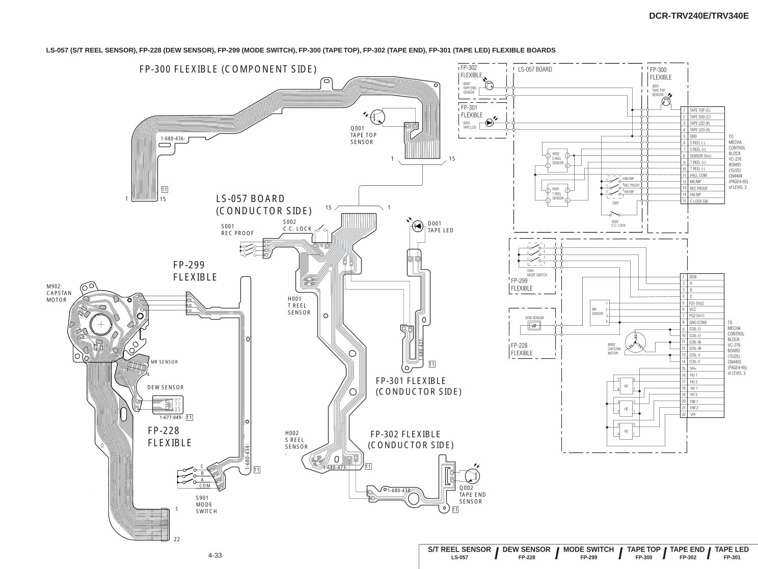
DCR-TRV240E/TRV340E
4-33
LS-057 (S/T REEL SENSOR), FP-228 (DEW SENSOR), FP-299 (MODE SWITCH), FP-300 (TAPE TOP), FP-302 (TAPE END), FP-301 (TAPE LED) FLEXIBLE BOARDS
FP-300 FLEXIBLE (COMPONENT SIDE)
LS-057 BOARD(CONDUCTOR SIDE)
FP-302 FLEXIBLE(CONDUCTOR SIDE)
1-680-438-
11
1-680-473- 11
1-68
0-43
7-
11
1-680-436-
11
D001TAPE LED
Q002TAPE END SENSOR
H001T REELSENSOR
S002C.C. LOCKS001
REC PROOF
H002 S REELSENSOR
FP-301 FLEXIBLE(CONDUCTOR SIDE)
1
1
15
1 1515
Q001 TAPE TOPSENSOR
o'o'
S901MODESWITCH
DEW SENSOR
1
22
M902CAPSTANMOTOR
FP-228FLEXIBLE
FP-299FLEXIBLE
1-68
0-43
4-
11
11
14
MR SENSOR
CBA
COM
1-677-049-
21
3
456
7
8
910111213
1415
1
2 3
4
1
2 3
4
S REEL SENSOR
T REEL SENSOR
H002
H001
TAPE TOP (C)
TAPE END (C)TAPE LED (K)
TAPE LED (A)GND
S REEL (-)
S REEL (+)
SENSOR (Vcc)T REEL (+)T REEL (-)
HALL COMME/MP
REC PROOFHi8 MP
C LOCK SW
FP-300 FLEXIBLE
LS-057 BOARDFP-302FLEXIBLE
FP-301FLEXIBLE
Q002TAPE ENDSENSOR
D001TAPE LED
Q001TAPE TOPSENSOR
S001
REC PROOF
Hi8 MP
ME/MP
S002C.C. LOCK
1 2
34
56
78
91011
12
13
14
15
16
VH-
17
18
1920
MR SENSOR
1
2
3
4
FP-299FLEXIBLE
FP-228FLEXIBLE
DEW SENSOR
HE
HE
HE
21
22
1
23
4
1
23
4
1
23
4
DEWA
B
C
FG1 (Vo2)VCCFG2 (Vo1)
GND (C0M)
COIL-U
COIL-U
COIL-WCOIL-W
COIL-V
COIL-V
VH+
HU 1
HU 2
HV 1HV 2
HW 1HW 2
S901 MODE SWITCH
M902CAPSTANMOTOR
TO MECHA CONTROL BLOCKVC-276BOARD(15/25)CN4404(PAGE4-65)of LEVEL 3
TO MECHA CONTROLBLOCKVC-276BOARD(15/25)CN4403(PAGE4-65)of LEVEL 3
TAPE LEDFP-301
MODE SWITCHFP-299
TAPE TOPFP-300
TAPE ENDFP-302 ////DEW SENSOR
FP-228S/T REEL SENSOR
LS-057 /
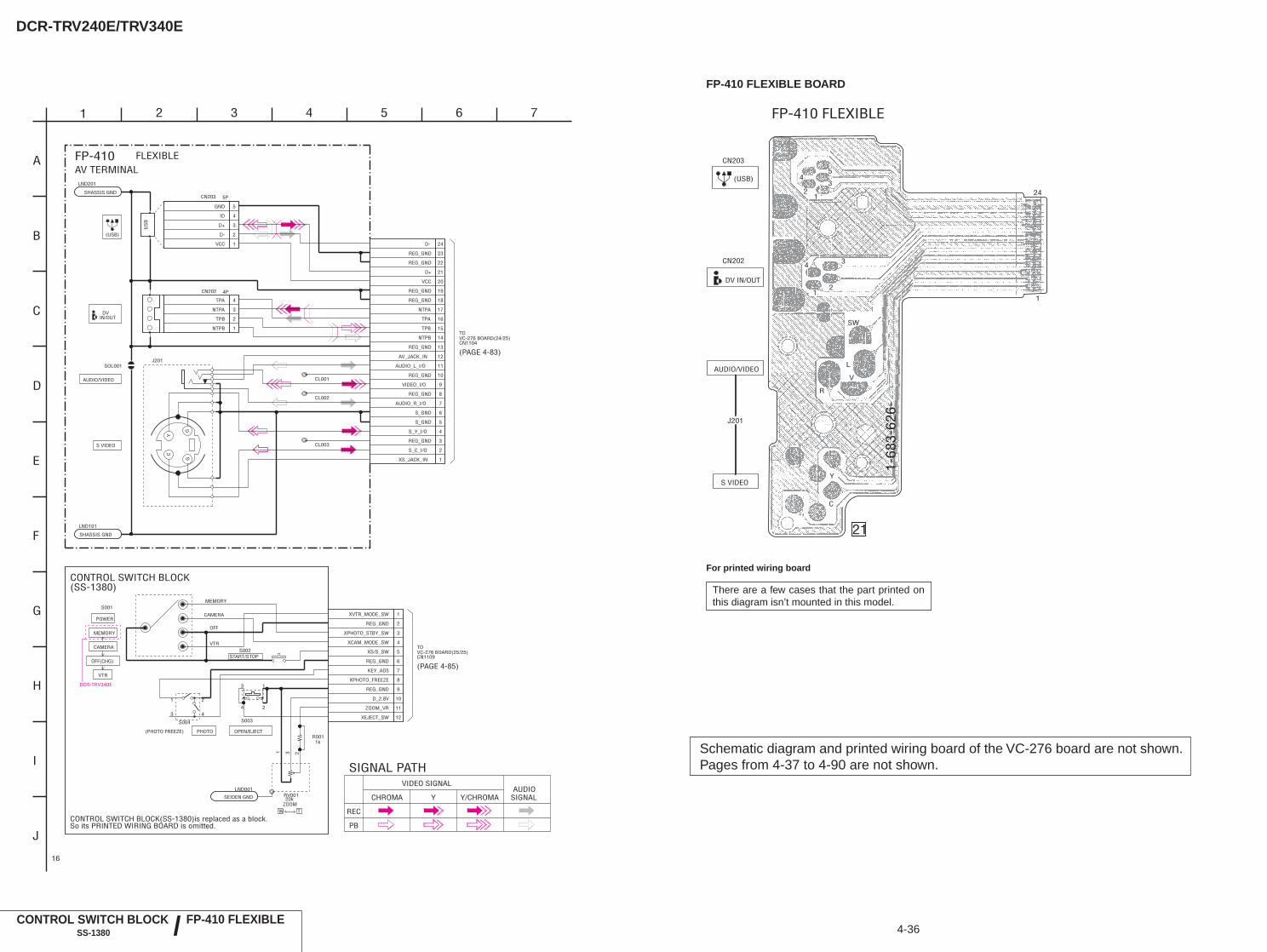
DCR-TRV240E/TRV340E
4-36CONTROL SWITCH BLOCK
SS-1380
FP-410 FLEXIBLE BOARD
FP-410 FLEXIBLE
21
(USB)
CN203
CN202
DV IN/OUT
J201
S VIDEO
AUDIO/VIDEO
1-68
3-62
6-
12
34
12
3
1
24
4
5
SW
L
V
R
Y
C
FP-410 FLEXIBLE/
Schematic diagram and printed wiring board of the VC-276 board are not shown.Pages from 4-37 to 4-90 are not shown.
For printed wiring board
There are a few cases that the part printed onthis diagram isn’t mounted in this model.
DCR-TRV340E
Y
GG
C
J201
LND101
LND201
4PCN202
1NTPB
2TPB
3NTPA
4TPA
CN203 5P
1VCC
2D-
3D+
4ID
5GND
SOL001
CL001
CL002
CL003
1
2
3
4
5
6
7
8
9
10
11
12
13
14
15
16
17
18
19
20
21
22
23
24
RV001
1 23
S003
1
2
3
4
LND001
SEIDEN GND
R0011k
S004
1 2
3 4
S0011
2
3
4
5
6
7
8
9
10
11
12
1
A
CAMERA
OFF
MEMORY
VTR
SHASSIS GND
SHASSIS GND
US
B
AV_JACK_IN
VIDEO_I/O
NTPA
TPB
D-
S_GND
REG_GND
AUDIO_L_I/O
NTPB
REG_GND
D+
S_C_I/O
REG_GND
S_Y_I/O
REG_GND
REG_GND
XS_JACK_IN
S_GND
REG_GND
AUDIO_R_I/O
TPA
REG_GND
REG_GND
VCC
T
(SS-1380)
20k
OFF(CHG)
XCAM_MODE_SW
W
CONTROL SWITCH BLOCK
CONTROL SWITCH BLOCK(SS-1380)is replaced as a block.So its PRINTED WIRING BOARD is omitted.
XPHOTO_FREEZE
XPHOTO_STBY_SW
REG_GND
REG_GND
KEY_AD5
XEJECT_SW
XS/S_SW
(PHOTO FREEZE)
VTR
ZOOM_VR
XVTR_MODE_SW
REG_GND
MEMORY
PHOTO
START/STOP
POWER
D_2.8V
OPEN/EJECT
CAMERA
(USB)
DVIN/OUT
AUDIO/VIDEO
S VIDEO
TOVC-276 BOARD(24/25)CN1104
(PAGE 4-83)
FP-410 FLEXIBLEAV TERMINAL
TOVC-276 BOARD(25/25)CN1109
(PAGE 4-85)
H
2 3
J
G
E
C
6
B
I
D
F
54
16
Y/CHROMAY
VIDEO SIGNAL
REC
SIGNAL PATH
AUDIOCHROMA
PB
SIGNAL
7
S002
ZOOM
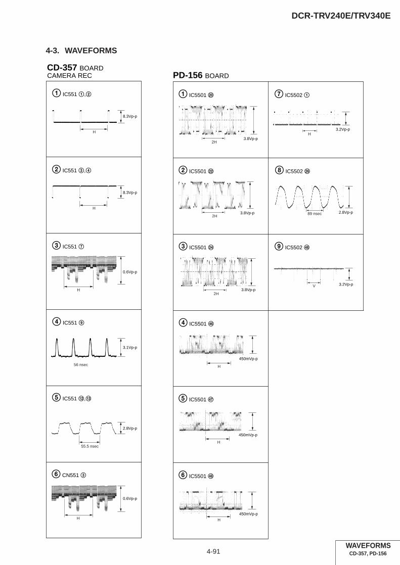
4-91
DCR-TRV240E/TRV340E
4-3. WAVEFORMS
WAVEFORMSCD-357, PD-156
CD-357 BOARD
2 IC551 3,4
3 IC551 7
4 IC551 9
0.6Vp-p
H
3.1Vp-p
56 nsec
5 IC551 qs,qd
55.5 nsec
2.8Vp-p
H
0.6Vp-p
6 CN551 3
1 IC551 1,2
8.3Vp-p
H
8.3Vp-p
H
CAMERA REC PD-156 BOARD
2 IC5501 ws
1 IC5501 w;
3.8Vp-p
3.8Vp-p
3.2Vp-p
3 IC5501 wf
3.8Vp-p
4 IC5501 rh
H
H
H
450mVp-p
5 IC5501 rj
450mVp-p
7 IC5502 1
6 IC5501 rk
H
450mVp-p
89 nsec 2.8Vp-p
8 IC5502 wh
V 3.2Vp-p
9 IC5502 rk
2H
2H
2H
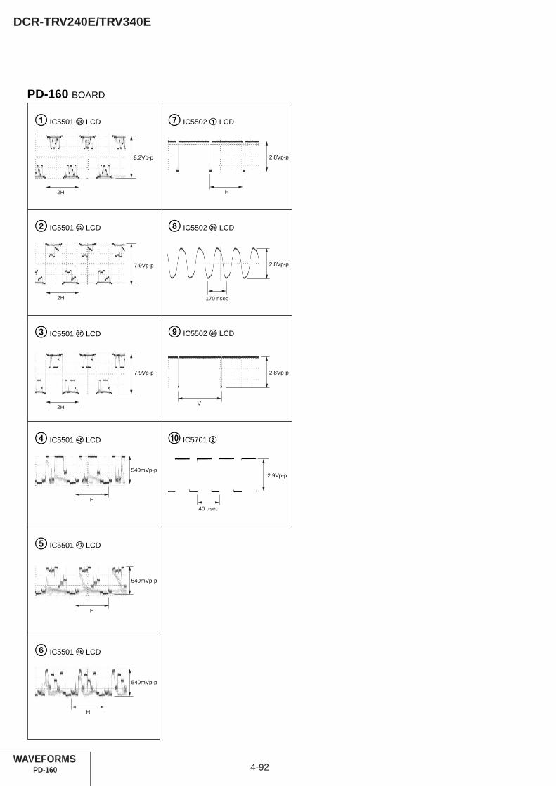
4-92
DCR-TRV240E/TRV340E
PD-160 BOARD
170 nsec
2H
2H
2H
H
1 IC5501 wf LCD 7 IC5502 1 LCD
2 IC5501 ws LCD 8 IC5502 wh LCD
9 IC5502 rk LCD3 IC5501 w; LCD
4 IC5501 rk LCD
5 IC5501 rj LCD
6 IC5501 rh LCD
8.2Vp-p
7.9Vp-p
7.9Vp-p
540mVp-p
H
540mVp-p
H
540mVp-p
H
2.8Vp-p
2.8Vp-p
2.8Vp-p
V
40 µsec
2.9Vp-p
0 IC5701 2
WAVEFORMSPD-160

Waveforms and mounted parts location of theVC-276 board are not shown.Pages from 4-93 to 4-97 are not shown.
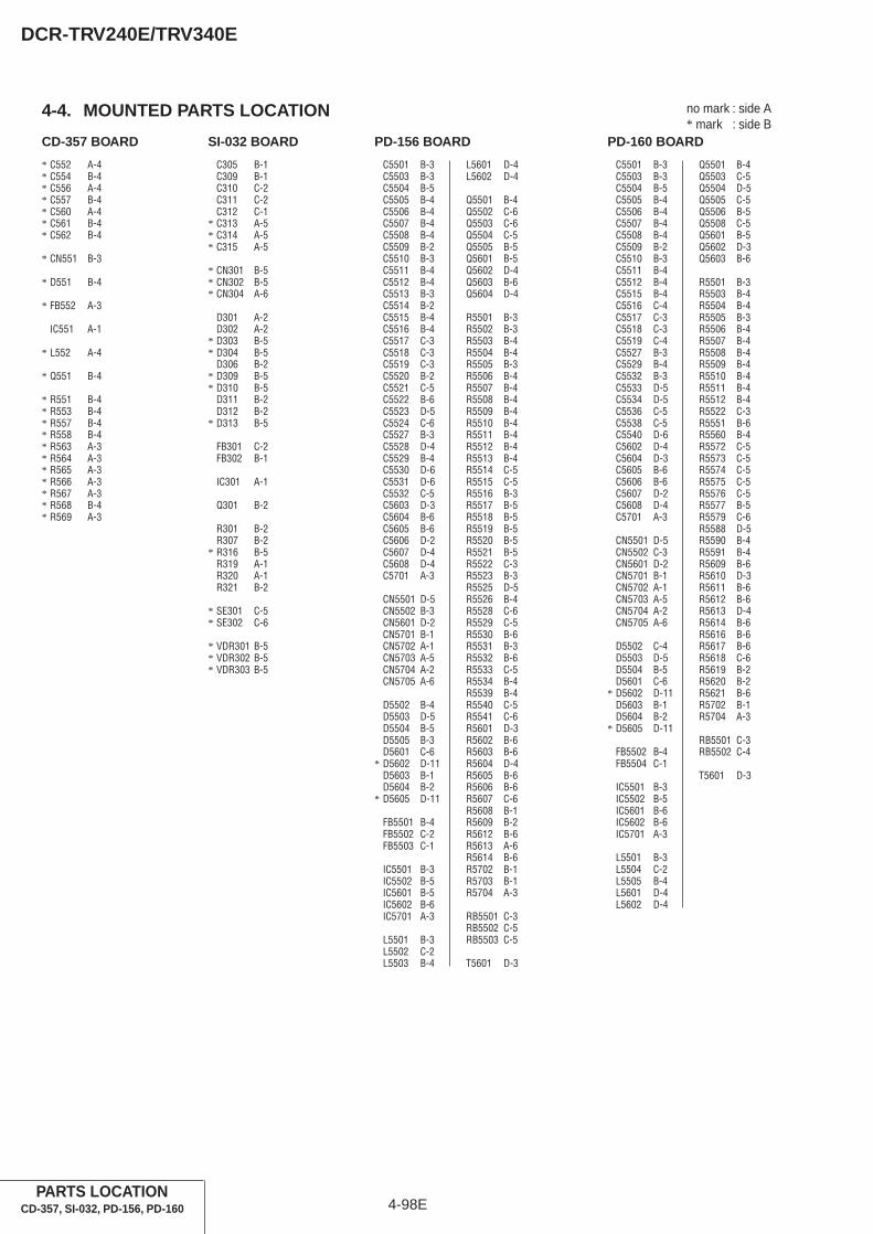
4-98E
DCR-TRV240E/TRV340E
4-4. MOUNTED PARTS LOCATION no mark : side A* mark : side B
CD-357 BOARD
* C552 A-4* C554 B-4* C556 A-4* C557 B-4* C560 A-4* C561 B-4* C562 B-4
* CN551 B-3
* D551 B-4
* FB552 A-3
IC551 A-1
* L552 A-4
* Q551 B-4
* R551 B-4* R553 B-4* R557 B-4* R558 B-4* R563 A-3* R564 A-3* R565 A-3* R566 A-3* R567 A-3* R568 B-4* R569 A-3
SI-032 BOARD
C305 B-1C309 B-1C310 C-2C311 C-2C312 C-1
* C313 A-5* C314 A-5* C315 A-5
* CN301 B-5* CN302 B-5* CN304 A-6
D301 A-2D302 A-2
* D303 B-5* D304 B-5
D306 B-2* D309 B-5* D310 B-5
D311 B-2D312 B-2
* D313 B-5
FB301 C-2FB302 B-1
IC301 A-1
Q301 B-2
R301 B-2R307 B-2
* R316 B-5R319 A-1R320 A-1R321 B-2
* SE301 C-5* SE302 C-6
* VDR301 B-5* VDR302 B-5* VDR303 B-5
PARTS LOCATIONCD-357, SI-032, PD-156, PD-160
PD-160 BOARD
C5501 B-3C5503 B-3C5504 B-5C5505 B-4C5506 B-4C5507 B-4C5508 B-4C5509 B-2C5510 B-3C5511 B-4C5512 B-4C5515 B-4C5516 C-4C5517 C-3C5518 C-3C5519 C-4C5527 B-3C5529 B-4C5532 B-3C5533 D-5C5534 D-5C5536 C-5C5538 C-5C5540 D-6C5602 D-4C5604 D-3C5605 B-6C5606 B-6C5607 D-2C5608 D-4C5701 A-3
CN5501 D-5CN5502 C-3CN5601 D-2CN5701 B-1CN5702 A-1CN5703 A-5CN5704 A-2CN5705 A-6
D5502 C-4D5503 D-5D5504 B-5D5601 C-6
* D5602 D-11D5603 B-1D5604 B-2
* D5605 D-11
FB5502 B-4FB5504 C-1
IC5501 B-3IC5502 B-5IC5601 B-6IC5602 B-6IC5701 A-3
L5501 B-3L5504 C-2L5505 B-4L5601 D-4L5602 D-4
Q5501 B-4Q5503 C-5Q5504 D-5Q5505 C-5Q5506 B-5Q5508 C-5Q5601 B-5Q5602 D-3Q5603 B-6
R5501 B-3R5503 B-4R5504 B-4R5505 B-3R5506 B-4R5507 B-4R5508 B-4R5509 B-4R5510 B-4R5511 B-4R5512 B-4R5522 C-3R5551 B-6R5560 B-4R5572 C-5R5573 C-5R5574 C-5R5575 C-5R5576 C-5R5577 B-5R5579 C-6R5588 D-5R5590 B-4R5591 B-4R5609 B-6R5610 D-3R5611 B-6R5612 B-6R5613 D-4R5614 B-6R5616 B-6R5617 B-6R5618 C-6R5619 B-2R5620 B-2R5621 B-6R5702 B-1R5704 A-3
RB5501 C-3RB5502 C-4
T5601 D-3
PD-156 BOARD
C5501 B-3C5503 B-3C5504 B-5C5505 B-4C5506 B-4C5507 B-4C5508 B-4C5509 B-2C5510 B-3C5511 B-4C5512 B-4C5513 B-3C5514 B-2C5515 B-4C5516 B-4C5517 C-3C5518 C-3C5519 C-3C5520 B-2C5521 C-5C5522 B-6C5523 D-5C5524 C-6C5527 B-3C5528 D-4C5529 B-4C5530 D-6C5531 D-6C5532 C-5C5603 D-3C5604 B-6C5605 B-6C5606 D-2C5607 D-4C5608 D-4C5701 A-3
CN5501 D-5CN5502 B-3CN5601 D-2CN5701 B-1CN5702 A-1CN5703 A-5CN5704 A-2CN5705 A-6
D5502 B-4D5503 D-5D5504 B-5D5505 B-3D5601 C-6
* D5602 D-11D5603 B-1D5604 B-2
* D5605 D-11
FB5501 B-4FB5502 C-2FB5503 C-1
IC5501 B-3IC5502 B-5IC5601 B-5IC5602 B-6IC5701 A-3
L5501 B-3L5502 C-2L5503 B-4
L5601 D-4L5602 D-4
Q5501 B-4Q5502 C-6Q5503 C-6Q5504 C-5Q5505 B-5Q5601 B-5Q5602 D-4Q5603 B-6Q5604 D-4
R5501 B-3R5502 B-3R5503 B-4R5504 B-4R5505 B-3R5506 B-4R5507 B-4R5508 B-4R5509 B-4R5510 B-4R5511 B-4R5512 B-4R5513 B-4R5514 C-5R5515 C-5R5516 B-3R5517 B-5R5518 B-5R5519 B-5R5520 B-5R5521 B-5R5522 C-3R5523 B-3R5525 D-5R5526 B-4R5528 C-6R5529 C-5R5530 B-6R5531 B-3R5532 B-6R5533 C-5R5534 B-4R5539 B-4R5540 C-5R5541 C-6R5601 D-3R5602 B-6R5603 B-6R5604 D-4R5605 B-6R5606 B-6R5607 C-6R5608 B-1R5609 B-2R5612 B-6R5613 A-6R5614 B-6R5702 B-1R5703 B-1R5704 A-3
RB5501 C-3RB5502 C-5RB5503 C-5
T5601 D-3

5-1
DCR-TRV240E/TRV340ESECTION 5
ADJUSTMENTS

5-2
DCR-TRV240E/TRV340E
Replaced partsBlock replacement Parts replacement
z
z z
z z
z z
z z
z z
z
z z
z
z z
z z
z
z
z
z z
z
z z
z z z z
z z
z z
z z z z
z z z z
z z z z
z z
z z z
z z
z z
z z
z
z z
z z
z z
z z
z z z z
Len
s de
vice
LC
D b
lock
ND
901
(Flu
ores
cent
tube
)
LC
D b
lock
LC
D90
1 (L
CD
pan
el)
Mec
hani
sm d
eck
*1
Mec
hani
sm d
eck
M90
1 (D
rum
ass
y.)
*1
Mec
hani
sm d
eck
M90
2 (C
apst
an m
otor
)
Mec
hani
sm d
eck
LS
cha
ssis
ass
y
CD
-357
boa
rdIC
551
(CC
D im
ager
)
PD-1
56/1
60 b
oard
IC55
01 (R
GB
driv
er (L
CD
)) *
5, *
6
PD-1
56/1
60 b
oard
IC55
02 (T
imin
g ge
nera
tor (
LCD
)) *5
, *6
PD-1
56/1
60 b
oard
Q56
02/5
604,
T56
01 (I
nver
ter)
*5, *
6
SI-0
32 b
oard
SE30
1,30
2 (P
ITC
H,Y
AW
sen
sor)
VC
-276
boa
rdIC
1501
, X15
01 (
Tim
ing
gene
rato
r )
VC
-276
boa
rdIC
1502
(S/
H, A
GC
)
VC
-276
boa
rdIC
2201
(H
i8/S
td8
Y/C
pro
cess
)
VC
-276
boa
rdIC
3103
(R
EC
/PB
AM
P)
VC
-276
boa
rdIC
3101
(E
Q, A
/D c
onv.
PL
L)
VC
-276
boa
rdIC
3701
VID
EO
IN
/OU
T)
VC
-276
boa
rdIC
3301
(D
V s
igna
l pro
cess
)
VC
-276
boa
rdIC
2291
(E
VR
)
VC
-276
boa
rdIC
5701
(A
UD
IO I
N/O
UT,
AFM
)
VC
-276
boa
rdIC
7001
(L
CD
dri
ver
(EV
F))
VC
-276
boa
rdIC
7002
(T
imin
g ge
nera
tor
(EV
F))
Table. 5-1-1 (1).
AdjustmentSection
Initialization of8, A, B, C, D,E, F, 1B, 1C,1F page data
Camera
EVF
LCD
System control
Servo & RF
Video
Audio
Mechanism
Adjustment
Initialization of D page data *3Initialization of A, D page data *2Initialization of B, 1B page data *2Initialization of 8, C, 1C page dataInitialization of E, F, 1F page dataHALL adj.Flange back adj.Optical axis adj.Color reproduction adj.AWB & LV standard data inputAuto white balance adj.Steady shot checkVCO adj.RGB AMP adj.Contrast adj.VCO adj.PSIG gray adj. *5RGB AMP adj.Black limit adj. *5Contrast adj.Center level adj. *5, COM AMP adj. *6V-COM adj.White balance adj.Serial No. inputREEL FG adj.Switching position adj.AGC center level adj.APC & AEQ adj.PLL f0 & LPF f0 adj.Hi8/Std8 switching position adj.CAP FG duty adj.36MHz origin oscillation adj.S VIDEO OUT Y level adj.S VIDEO OUT chroma level adj.Hi8/Std8 Y/C level settingHi8/Std8 AFC f0 adj.Hi8/Std8 AFM BPF f0 adj.Hi8/Std8 AFM 1.5MHz deviation adj.Hi8/Std8 AFM 1.7MHz deviation adj.Tape path adj.
1. Adjusting items when replacing main parts and boards.When replacing main parts, adjust the items indicated by z in the following table.
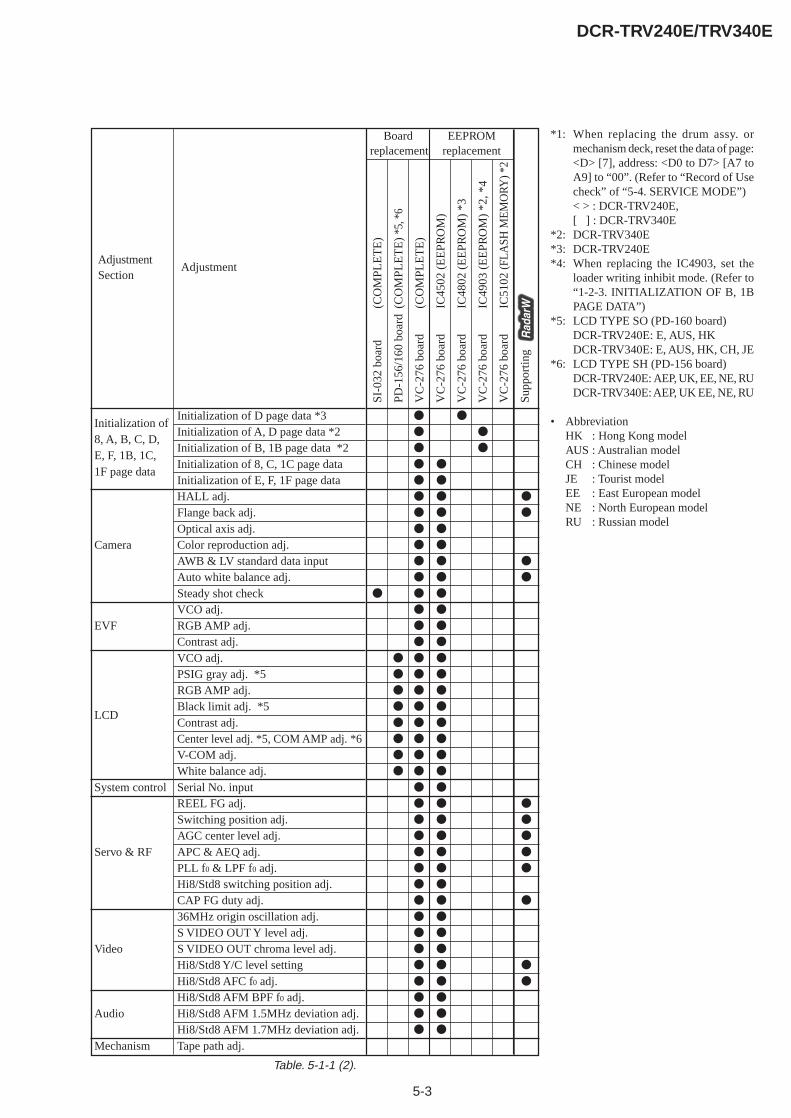
5-3
DCR-TRV240E/TRV340E
Board EEPROMreplacement replacement
z z
z z
z z
z z
z z
z z z
z z z
z z
z z
z z z
z z z
z z z
z z
z z
z z
z z z
z z z
z z z
z z z
z z z
z z z
z z z
z z z
z z
z z z
z z z
z z z
z z z
z z z
z z
z z z
z z
z z
z z
z z z
z z z
z z
z z
z z
SI-0
32 b
oard
(CO
MPL
ET
E)
PD-1
56/1
60 b
oard
(CO
MPL
ET
E)
*5, *
6
VC
-276
boa
rd(C
OM
PLE
TE
)
VC
-276
boa
rdIC
4502
(E
EPR
OM
)
VC
-276
boa
rdIC
4802
(E
EPR
OM
) *3
VC
-276
boa
rdIC
4903
(E
EPR
OM
) *2
, *4
VC
-276
boa
rdIC
5102
(FL
ASH
ME
MO
RY) *
2
Supp
ortin
g
Table. 5-1-1 (2).
AdjustmentSection
Initialization of8, A, B, C, D,E, F, 1B, 1C,1F page data
Camera
EVF
LCD
System control
Servo & RF
Video
Audio
Mechanism
Adjustment
Initialization of D page data *3Initialization of A, D page data *2Initialization of B, 1B page data *2Initialization of 8, C, 1C page dataInitialization of E, F, 1F page dataHALL adj.Flange back adj.Optical axis adj.Color reproduction adj.AWB & LV standard data inputAuto white balance adj.Steady shot checkVCO adj.RGB AMP adj.Contrast adj.VCO adj.PSIG gray adj. *5RGB AMP adj.Black limit adj. *5Contrast adj.Center level adj. *5, COM AMP adj. *6V-COM adj.White balance adj.Serial No. inputREEL FG adj.Switching position adj.AGC center level adj.APC & AEQ adj.PLL f0 & LPF f0 adj.Hi8/Std8 switching position adj.CAP FG duty adj.36MHz origin oscillation adj.S VIDEO OUT Y level adj.S VIDEO OUT chroma level adj.Hi8/Std8 Y/C level settingHi8/Std8 AFC f0 adj.Hi8/Std8 AFM BPF f0 adj.Hi8/Std8 AFM 1.5MHz deviation adj.Hi8/Std8 AFM 1.7MHz deviation adj.Tape path adj.
*1: When replacing the drum assy. ormechanism deck, reset the data of page:<D> [7], address: <D0 to D7> [A7 toA9] to “00”. (Refer to “Record of Usecheck” of “5-4. SERVICE MODE”)< > : DCR-TRV240E,[ ] : DCR-TRV340E
*2: DCR-TRV340E*3: DCR-TRV240E*4: When replacing the IC4903, set the
loader writing inhibit mode. (Refer to“1-2-3. INITIALIZATION OF B, 1BPAGE DATA”)
*5: LCD TYPE SO (PD-160 board)DCR-TRV240E: E, AUS, HKDCR-TRV340E: E, AUS, HK, CH, JE
*6: LCD TYPE SH (PD-156 board)DCR-TRV240E: AEP, UK, EE, NE, RUDCR-TRV340E: AEP, UK EE, NE, RU
• AbbreviationHK : Hong Kong modelAUS : Australian modelCH : Chinese modelJE : Tourist modelEE : East European modelNE : North European modelRU : Russian model
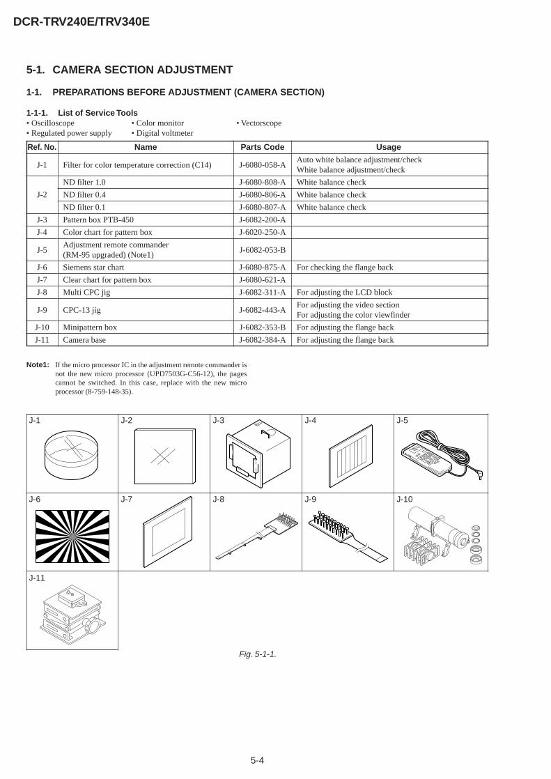
5-4
DCR-TRV240E/TRV340E
Ref. No.
J-1
J-2
J-3
J-4
J-5
J-6
J-7
J-8
J-9
J-10
J-11
Name
Filter for color temperature correction (C14)
ND filter 1.0
ND filter 0.4
ND filter 0.1
Pattern box PTB-450
Color chart for pattern box
Adjustment remote commander(RM-95 upgraded) (Note1)
Siemens star chart
Clear chart for pattern box
Multi CPC jig
CPC-13 jig
Minipattern box
Camera base
Parts Code
J-6080-058-A
J-6080-808-A
J-6080-806-A
J-6080-807-A
J-6082-200-A
J-6020-250-A
J-6082-053-B
J-6080-875-A
J-6080-621-A
J-6082-311-A
J-6082-443-A
J-6082-353-B
J-6082-384-A
Usage
Auto white balance adjustment/checkWhite balance adjustment/check
White balance check
White balance check
White balance check
For checking the flange back
For adjusting the LCD block
For adjusting the video sectionFor adjusting the color viewfinder
For adjusting the flange back
For adjusting the flange back
J-1 J-2
J-6
J-3
J-7 J-8
J-4 J-5
Fig. 5-1-1.
J-9 J-10
J-11
5-1. CAMERA SECTION ADJUSTMENT
1-1. PREPARATIONS BEFORE ADJUSTMENT (CAMERA SECTION)
1-1-1. List of Service Tools• Oscilloscope • Color monitor • Vectorscope• Regulated power supply • Digital voltmeter
Note1: If the micro processor IC in the adjustment remote commander isnot the new micro processor (UPD7503G-C56-12), the pagescannot be switched. In this case, replace with the new microprocessor (8-759-148-35).
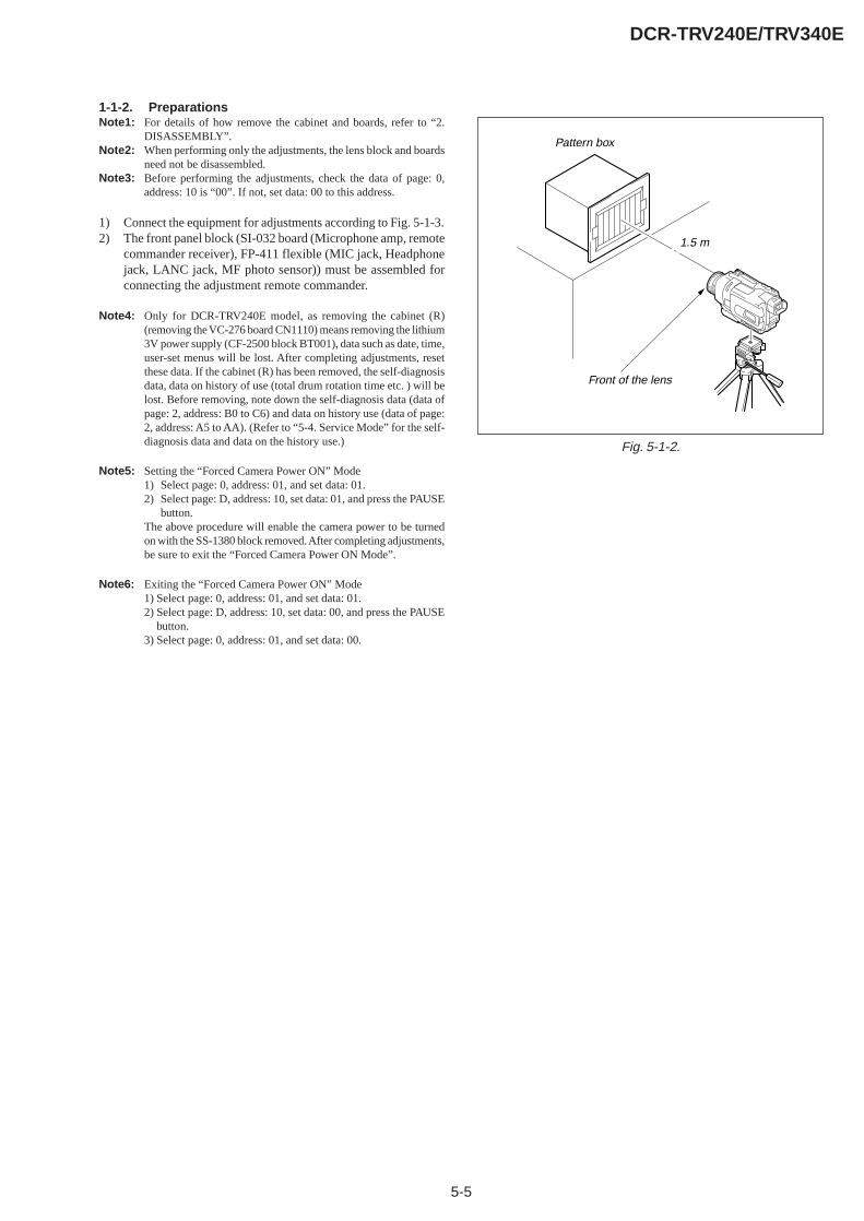
5-5
DCR-TRV240E/TRV340E
Fig. 5-1-2.
1-1-2. PreparationsNote1: For details of how remove the cabinet and boards, refer to “2.
DISASSEMBLY”.Note2: When performing only the adjustments, the lens block and boards
need not be disassembled.Note3: Before performing the adjustments, check the data of page: 0,
address: 10 is “00”. If not, set data: 00 to this address.
1) Connect the equipment for adjustments according to Fig. 5-1-3.2) The front panel block (SI-032 board (Microphone amp, remote
commander receiver), FP-411 flexible (MIC jack, Headphonejack, LANC jack, MF photo sensor)) must be assembled forconnecting the adjustment remote commander.
Note4: Only for DCR-TRV240E model, as removing the cabinet (R)(removing the VC-276 board CN1110) means removing the lithium3V power supply (CF-2500 block BT001), data such as date, time,user-set menus will be lost. After completing adjustments, resetthese data. If the cabinet (R) has been removed, the self-diagnosisdata, data on history of use (total drum rotation time etc. ) will belost. Before removing, note down the self-diagnosis data (data ofpage: 2, address: B0 to C6) and data on history use (data of page:2, address: A5 to AA). (Refer to “5-4. Service Mode” for the self-diagnosis data and data on the history use.)
Note5: Setting the “Forced Camera Power ON” Mode1) Select page: 0, address: 01, and set data: 01.2) Select page: D, address: 10, set data: 01, and press the PAUSE
button.The above procedure will enable the camera power to be turnedon with the SS-1380 block removed. After completing adjustments,be sure to exit the “Forced Camera Power ON Mode”.
Note6: Exiting the “Forced Camera Power ON” Mode1) Select page: 0, address: 01, and set data: 01.2) Select page: D, address: 10, set data: 00, and press the PAUSE
button.3) Select page: 0, address: 01, and set data: 00.
Front of the lens
1.5 m
Pattern box
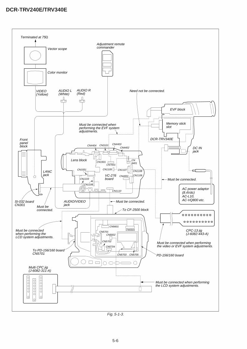
5-6
DCR-TRV240E/TRV340E
Fig. 5-1-3.
Color monitor
AUDIO/VIDEOjack
LANC jack VC-276
board
VIDEO(Yellow)
Vector scope
Terminated at 75Ω
DCR-TRV340E
CN1103
CN1551
CN7001
CN1105
CN1501
CN4404 CN3101 CN4403CN4402
CN4401
CN1108
CN1109
CN1107
CN4001
CN1106
CN1110
Must be connected when performingthe LCD system adjustments.
Must be connected when performing the EVF system adjustments.
Lens block
EVF block
Memory stickslot
Front panel block
To CF-2500 blockMust be connected.
Must be connected.
Need not be connected.
SI-032 boardCN301
Adjustment remotecommander
AUDIO L(White)
AUDIO R(Red)
DC IN jack
AC power adaptor (8.4Vdc)AC-L10,AC-VQ800 etc.
CPC-13 jig(J-6082-443-A)
Multi CPC jig(J-6082-311-A)
CN5701CN5502
CN5702
CN5704
CN5703 CN5705
CN5601CN5501
To PD-156/160 boardCN5701
Must be connected when performingthe video or EVF system adjustments.
Must be connectedwhen performing the LCD system adjustments.
PD-156/160 board
Must be connected.
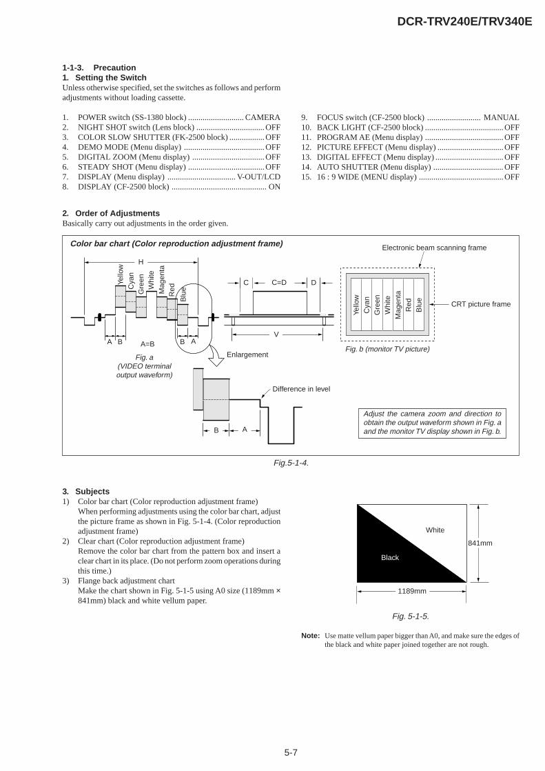
5-7
DCR-TRV240E/TRV340E
H
A=B
C=D
A B B
C D
A
Enlargement
V
Electronic beam scanning frame
CRT picture frame
B A
Difference in level
Yello
wC
yan
Gre
enW
hite
Mag
enta
Red
Blu
e
Yello
wC
yan
Gre
enW
hite
Mag
enta
Red
Blu
e
Color bar chart (Color reproduction adjustment frame)
Fig. a(VIDEO terminaloutput waveform)
Fig. b (monitor TV picture)
Adjust the camera zoom and direction toobtain the output waveform shown in Fig. aand the monitor TV display shown in Fig. b.
White
Black
841mm
1189mm
1-1-3. Precaution1. Setting the SwitchUnless otherwise specified, set the switches as follows and performadjustments without loading cassette.
1. POWER switch (SS-1380 block) ........................... CAMERA2. NIGHT SHOT switch (Lens block) .................................OFF3. COLOR SLOW SHUTTER (FK-2500 block) .................OFF4. DEMO MODE (Menu display) ....................................... OFF5. DIGITAL ZOOM (Menu display) ................................... OFF6. STEADY SHOT (Menu display) .....................................OFF7. DISPLAY (Menu display) ................................. V-OUT/LCD8. DISPLAY (CF-2500 block) .............................................. ON
9. FOCUS switch (CF-2500 block) .......................... MANUAL10. BACK LIGHT (CF-2500 block) ...................................... OFF11. PROGRAM AE (Menu display) ...................................... OFF12. PICTURE EFFECT (Menu display) ................................OFF13. DIGITAL EFFECT (Menu display) .................................OFF14. AUTO SHUTTER (Menu display) .................................. OFF15. 16 : 9 WIDE (MENU display) .........................................OFF
2. Order of AdjustmentsBasically carry out adjustments in the order given.
Fig.5-1-4.
3. Subjects1) Color bar chart (Color reproduction adjustment frame)
When performing adjustments using the color bar chart, adjustthe picture frame as shown in Fig. 5-1-4. (Color reproductionadjustment frame)
2) Clear chart (Color reproduction adjustment frame)Remove the color bar chart from the pattern box and insert aclear chart in its place. (Do not perform zoom operations duringthis time.)
3) Flange back adjustment chartMake the chart shown in Fig. 5-1-5 using A0 size (1189mm ×841mm) black and white vellum paper.
Fig. 5-1-5.
Note: Use matte vellum paper bigger than A0, and make sure the edges ofthe black and white paper joined together are not rough.
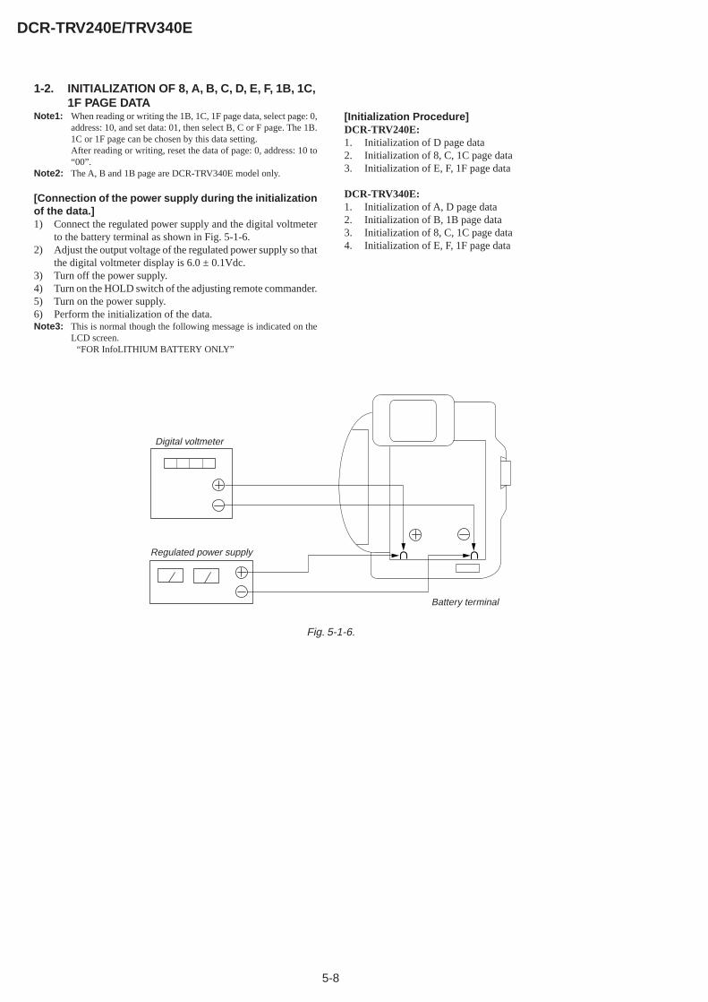
5-8
DCR-TRV240E/TRV340E
1-2. INITIALIZATION OF 8, A, B, C, D, E, F, 1B, 1C,1F PAGE DATA
Note1: When reading or writing the 1B, 1C, 1F page data, select page: 0,address: 10, and set data: 01, then select B, C or F page. The 1B.1C or 1F page can be chosen by this data setting.After reading or writing, reset the data of page: 0, address: 10 to“00”.
Note2: The A, B and 1B page are DCR-TRV340E model only.
[Connection of the power supply during the initializationof the data.]1) Connect the regulated power supply and the digital voltmeter
to the battery terminal as shown in Fig. 5-1-6.2) Adjust the output voltage of the regulated power supply so that
the digital voltmeter display is 6.0 ± 0.1Vdc.3) Turn off the power supply.4) Turn on the HOLD switch of the adjusting remote commander.5) Turn on the power supply.6) Perform the initialization of the data.Note3: This is normal though the following message is indicated on the
LCD screen.“FOR InfoLITHIUM BATTERY ONLY”
[Initialization Procedure]DCR-TRV240E:1. Initialization of D page data2. Initialization of 8, C, 1C page data3. Initialization of E, F, 1F page data
DCR-TRV340E:1. Initialization of A, D page data2. Initialization of B, 1B page data3. Initialization of 8, C, 1C page data4. Initialization of E, F, 1F page data
Digital voltmeter
Regulated power supply
Battery terminal
Fig. 5-1-6.
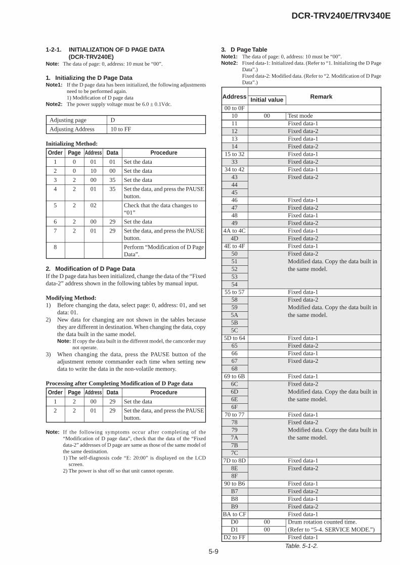
5-9
DCR-TRV240E/TRV340E
1-2-1. INITIALIZATION OF D PAGE DATA(DCR-TRV240E)
Note: The data of page: 0, address: 10 must be “00”.
1. Initializing the D Page DataNote1: If the D page data has been initialized, the following adjustments
need to be performed again.1) Modification of D page data
Note2: The power supply voltage must be 6.0 ± 0.1Vdc.
Adjusting page D
Adjusting Address 10 to FF
Initializing Method:
Order Page Address Data Procedure
1 0 01 01 Set the data
2 0 10 00 Set the data
3 2 00 35 Set the data
4 2 01 35 Set the data, and press the PAUSEbutton.
5 2 02 Check that the data changes to“01”
6 2 00 29 Set the data
7 2 01 29 Set the data, and press the PAUSEbutton.
8 Perform “Modification of D PageData”.
2. Modification of D Page DataIf the D page data has been initialized, change the data of the “Fixeddata-2” address shown in the following tables by manual input.
Modifying Method:1) Before changing the data, select page: 0, address: 01, and set
data: 01.2) New data for changing are not shown in the tables because
they are different in destination. When changing the data, copythe data built in the same model.Note: If copy the data built in the different model, the camcorder may
not operate.3) When changing the data, press the PAUSE button of the
adjustment remote commander each time when setting newdata to write the data in the non-volatile memory.
Processing after Completing Modification of D Page data
Order Page Address Data Procedure
1 2 00 29 Set the data
2 2 01 29 Set the data, and press the PAUSEbutton.
Note: If the following symptoms occur after completing of the“Modification of D page data”, check that the data of the “Fixeddata-2” addresses of D page are same as those of the same model ofthe same destination.1) The self-diagnosis code “E: 20:00” is displayed on the LCD
screen.2) The power is shut off so that unit cannot operate.
3. D Page TableNote1: The data of page: 0, address: 10 must be “00”.Note2: Fixed data-1: Initialized data. (Refer to “1. Initializing the D Page
Data”.)Fixed data-2: Modified data. (Refer to “2. Modification of D PageData”.)
00 to 0F1011121314
15 to 3233
34 to 4243444546474849
4A to 4C4D
4E to 4F5051525354
55 to 5758595A5B5C
5D to 6465666768
69 to 6B6C6D6E6F
70 to 7778797A7B7C
7D to 8D8E8F
90 to B6B7B8B9
BA to CFD0D1
D2 to FF
00
0000
Test modeFixed data-1Fixed data-2Fixed data-1Fixed data-2Fixed data-1Fixed data-2Fixed data-1Fixed data-2
Fixed data-1Fixed data-2Fixed data-1Fixed data-2Fixed data-1Fixed data-2Fixed data-1Fixed data-2Modified data. Copy the data built inthe same model.
Fixed data-1Fixed data-2Modified data. Copy the data built inthe same model.
Fixed data-1Fixed data-2Fixed data-1Fixed data-2
Fixed data-1Fixed data-2Modified data. Copy the data built inthe same model.
Fixed data-1Fixed data-2Modified data. Copy the data built inthe same model.
Fixed data-1Fixed data-2
Fixed data-1Fixed data-2Fixed data-1Fixed data-2Fixed data-1Drum rotation counted time.(Refer to “5-4. SERVICE MODE.”)Fixed data-1
Address RemarkInitial value
Table. 5-1-2.
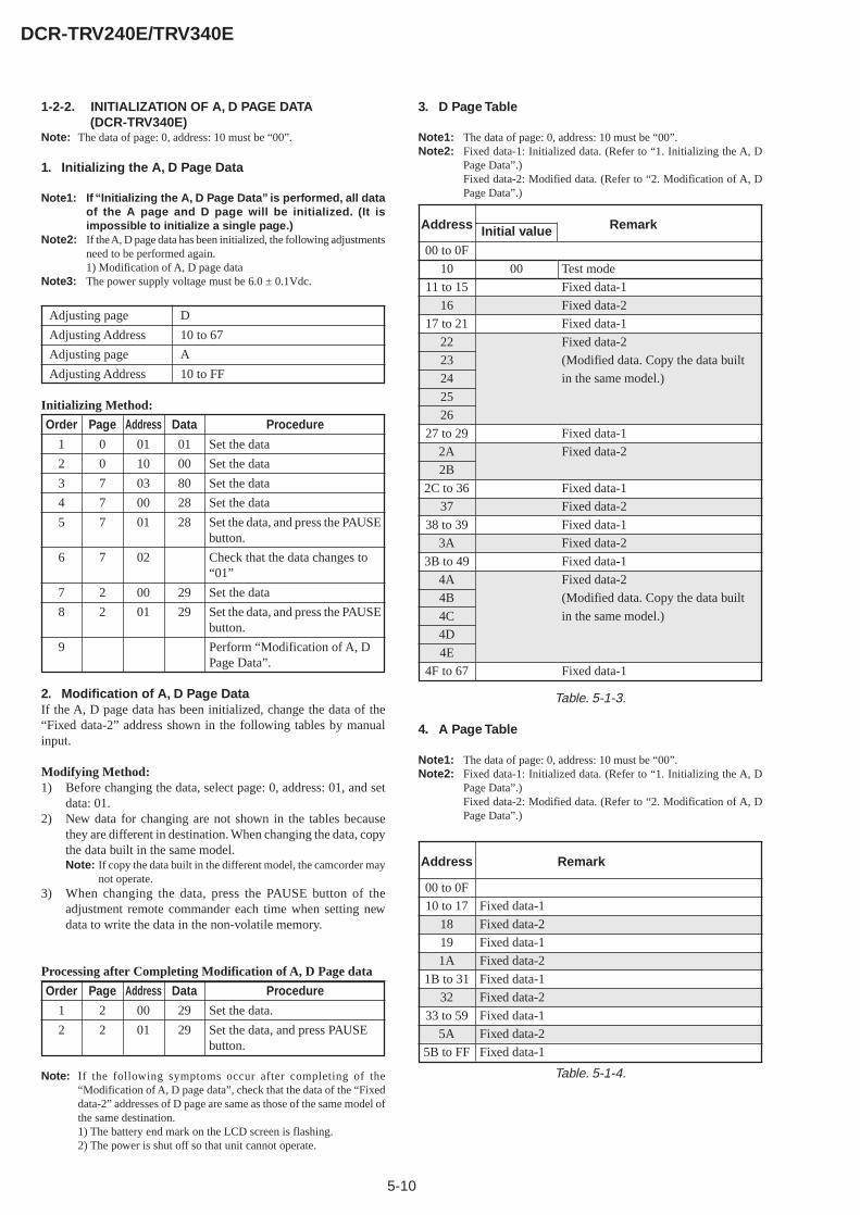
5-10
DCR-TRV240E/TRV340E
1-2-2. INITIALIZATION OF A, D PAGE DATA(DCR-TRV340E)
Note: The data of page: 0, address: 10 must be “00”.
1. Initializing the A, D Page Data
Note1: If “Initializing the A, D Page Data” is performed, all dataof the A page and D page will be initialized. (It isimpossible to initialize a single page.)
Note2: If the A, D page data has been initialized, the following adjustmentsneed to be performed again.1) Modification of A, D page data
Note3: The power supply voltage must be 6.0 ± 0.1Vdc.
Adjusting page D
Adjusting Address 10 to 67
Adjusting page A
Adjusting Address 10 to FF
Initializing Method:
Order Page Address Data Procedure
1 0 01 01 Set the data
2 0 10 00 Set the data
3 7 03 80 Set the data
4 7 00 28 Set the data
5 7 01 28 Set the data, and press the PAUSEbutton.
6 7 02 Check that the data changes to“01”
7 2 00 29 Set the data
8 2 01 29 Set the data, and press the PAUSEbutton.
9 Perform “Modification of A, DPage Data”.
2. Modification of A, D Page DataIf the A, D page data has been initialized, change the data of the“Fixed data-2” address shown in the following tables by manualinput.
Modifying Method:1) Before changing the data, select page: 0, address: 01, and set
data: 01.2) New data for changing are not shown in the tables because
they are different in destination. When changing the data, copythe data built in the same model.Note: If copy the data built in the different model, the camcorder may
not operate.3) When changing the data, press the PAUSE button of the
adjustment remote commander each time when setting newdata to write the data in the non-volatile memory.
Processing after Completing Modification of A, D Page data
Order Page Address Data Procedure
1 2 00 29 Set the data.
2 2 01 29 Set the data, and press PAUSEbutton.
Note: If the following symptoms occur after completing of the“Modification of A, D page data”, check that the data of the “Fixeddata-2” addresses of D page are same as those of the same model ofthe same destination.1) The battery end mark on the LCD screen is flashing.2) The power is shut off so that unit cannot operate.
3. D Page Table
Note1: The data of page: 0, address: 10 must be “00”.Note2: Fixed data-1: Initialized data. (Refer to “1. Initializing the A, D
Page Data”.)Fixed data-2: Modified data. (Refer to “2. Modification of A, DPage Data”.)
Table. 5-1-4.
00 to 0F
10
11 to 15
16
17 to 21
22
23
24
25
26
27 to 29
2A
2B
2C to 36
37
38 to 39
3A
3B to 49
4A
4B
4C
4D
4E
4F to 67
00 Test mode
Fixed data-1
Fixed data-2
Fixed data-1
Fixed data-2
(Modified data. Copy the data built
in the same model.)
Fixed data-1
Fixed data-2
Fixed data-1
Fixed data-2
Fixed data-1
Fixed data-2
Fixed data-1
Fixed data-2
(Modified data. Copy the data built
in the same model.)
Fixed data-1
Address RemarkInitial value
00 to 0F
10 to 17
18
19
1A
1B to 31
32
33 to 59
5A
5B to FF
Fixed data-1
Fixed data-2
Fixed data-1
Fixed data-2
Fixed data-1
Fixed data-2
Fixed data-1
Fixed data-2
Fixed data-1
Address Remark
Table. 5-1-3.
4. A Page Table
Note1: The data of page: 0, address: 10 must be “00”.Note2: Fixed data-1: Initialized data. (Refer to “1. Initializing the A, D
Page Data”.)Fixed data-2: Modified data. (Refer to “2. Modification of A, DPage Data”.)

5-11
DCR-TRV240E/TRV340E
1-2-3. INITIALIZATION OF B, 1B PAGE DATA(DCR-TRV340E)
Note: When reading or writing the B page data, select page: 0, address:10, and set data: 00.When reading or writing the 1B page data, select page: 0, address:10, and set data: 01, then select B page. The 1B page can be chosenby this data setting.After reading or writing, reset the data of page: 0, address: 10 to“00”.
1. Initializing the B, 1B Page Data
Note1: If “Initializing the B, 1B Page Data” is performed, all dataof the B page and 1B page will be initialized. (It isimpossible to initialize a single page.)
Note2: If the B, 1B page data has been initialized, the followingadjustments need to be performed again.1) Modification of B, 1B page data
Note3: The power supply voltage must be 6.0 ± 0.1Vdc.
Adjusting page B
Adjusting Address 00 to FF
Adjusting page 1B
Adjusting Address 00 to FF
Initializing Method:
Order Page Address Data Procedure
1 0 01 01 Set the data.
2 0 10 00 Set the data.
3 5 02 FF Set the data.
4 5 01 F3 Set the data, and press PAUSEbutton.
5 5 00 01 Set the data, and press PAUSEbutton.
6 5 02 Check that the data changes to“00”.
7 2 00 29 Set the data
8 2 01 29 Set the data, and press the PAUSEbutton.
9 Perform “Modification of B, 1BPage Data”.
2. Modification of B, 1B Page DataIf the B, 1B page data has been initialized, change the data of the“Fixed data-2” address shown in the following tables by manualinput.
Modifying Method:1) Before changing the data, select page: 0, address: 01, and set
data: 01.2) When changing the B page data, select page: 0, address: 10,
and set data: 00.3) When changing the 1B page data, select page: 0, address: 10,
and set data: 01.After completing the modification of 1B page data, reset thedata of this address to “00”.
4) New data for changing are not shown in the tables becausethey are different in destination. When changing the data, copythe data built in the same model.Note: If copy the data built in the different model, the camcorder may
not operate.5) When changing the data, press the PAUSE button of the
adjustment remote commander each time when setting newdata to write the data in the non-volatile memory.
Processing after Completing Modification of B, 1B Page data:
Order Page Address Data Procedure
1 0 10 00 Set the data.
2 2 00 29 Set the data.
3 2 01 29 Set the data, and press PAUSEbutton.
3. Loader writing inhibit mode settingWhen replacing the IC4903 (EEPROM), set the loader writing inhibitmode.
Setting method:
Order Page Address Data Procedure
1 0 01 01 Set the data.
2 0 10 00 Set the data.
3 5 0E 00 Set the data and press PAUSEbutton.
4 5 03 20 Set the data and press PAUSEbutton.
5 5 01 FA Set the data and press PAUSEbutton.
6 5 00 01 Set the data and press PAUSEbutton.
7 5 0E Check that the data is “01”.
8 2 00 29 Set the data.
9 2 01 29 Set the data and press PAUSEbutton.
4. B Page Table
Note1: The data of page: 0, address: 10 must be “00”.Note2: Fixed data-1: Initialized data. (Refer to “1. Initializing the B, 1B
Page Data”.)Fixed data-2: Modified data. (Refer to “2. Modification of B, 1BPage Data”.)
00 to 8C
8D
8E to FF
Fixed data-1
Fixed data-2
Fixed data-1
Address Remark
00 to FF Fixed data-1
Address Remark
Table. 5-1-5.
5. 1B Page Table
Note1: When reading or writing the 1B page data, select page: 0, address:10, and set data: 01, then select B page. The 1B page can be chosenby this data setting.After reading or writing, reset the data of page: 0, address: 10 to“00”.
Note2: Fixed data-1: Initialized data. (Refer to “1. Initializing the B, 1BPage Data”.)Fixed data-2: Modified data. (Refer to “2. Modification of B, 1BPage Data”.)
Table. 5-1-6.
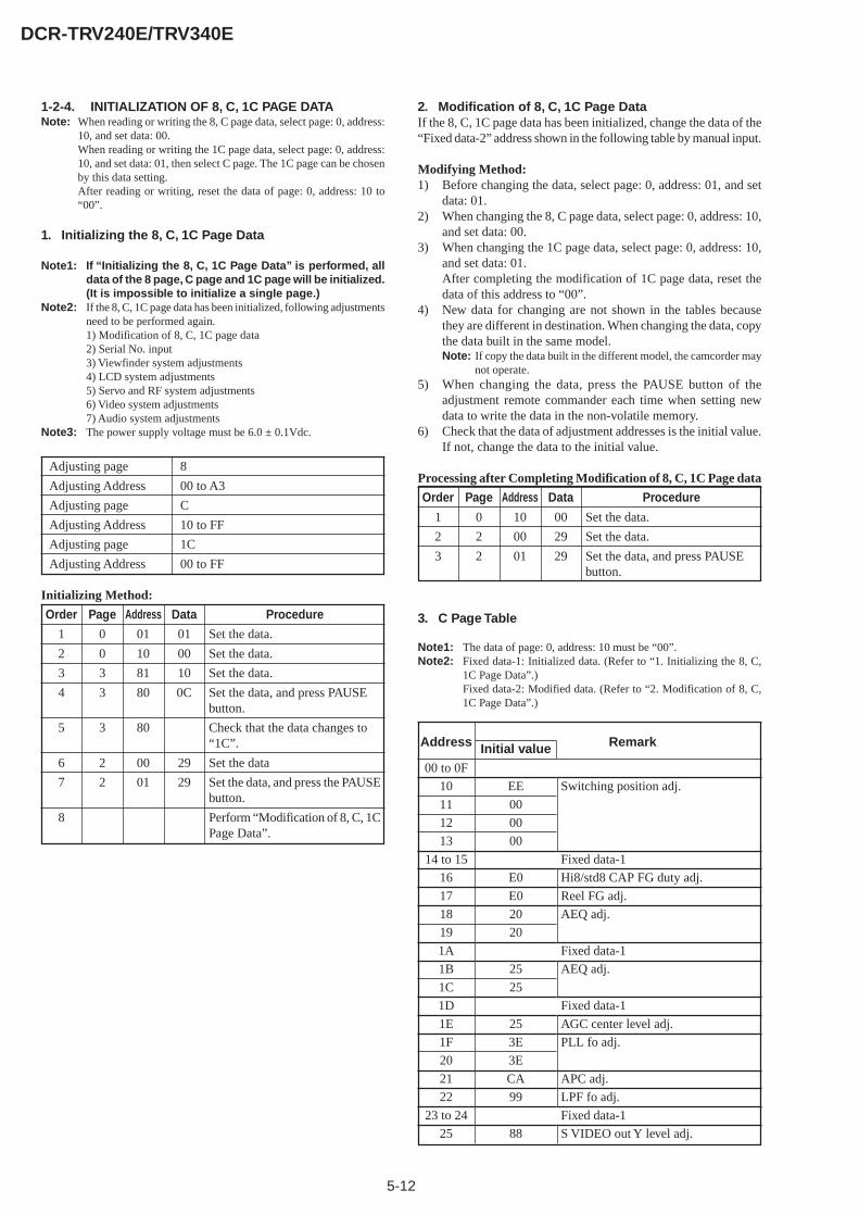
5-12
DCR-TRV240E/TRV340E
1-2-4. INITIALIZATION OF 8, C, 1C PAGE DATANote: When reading or writing the 8, C page data, select page: 0, address:
10, and set data: 00.When reading or writing the 1C page data, select page: 0, address:10, and set data: 01, then select C page. The 1C page can be chosenby this data setting.After reading or writing, reset the data of page: 0, address: 10 to“00”.
1. Initializing the 8, C, 1C Page Data
Note1: If “Initializing the 8, C, 1C Page Data” is performed, alldata of the 8 page, C page and 1C page will be initialized.(It is impossible to initialize a single page.)
Note2: If the 8, C, 1C page data has been initialized, following adjustmentsneed to be performed again.1) Modification of 8, C, 1C page data2) Serial No. input3) Viewfinder system adjustments4) LCD system adjustments5) Servo and RF system adjustments6) Video system adjustments7) Audio system adjustments
Note3: The power supply voltage must be 6.0 ± 0.1Vdc.
Adjusting page 8
Adjusting Address 00 to A3
Adjusting page C
Adjusting Address 10 to FF
Adjusting page 1C
Adjusting Address 00 to FF
Initializing Method:
Order Page Address Data Procedure
1 0 01 01 Set the data.
2 0 10 00 Set the data.
3 3 81 10 Set the data.
4 3 80 0C Set the data, and press PAUSEbutton.
5 3 80 Check that the data changes to“1C”.
6 2 00 29 Set the data
7 2 01 29 Set the data, and press the PAUSEbutton.
8 Perform “Modification of 8, C, 1CPage Data”.
2. Modification of 8, C, 1C Page DataIf the 8, C, 1C page data has been initialized, change the data of the“Fixed data-2” address shown in the following table by manual input.
Modifying Method:1) Before changing the data, select page: 0, address: 01, and set
data: 01.2) When changing the 8, C page data, select page: 0, address: 10,
and set data: 00.3) When changing the 1C page data, select page: 0, address: 10,
and set data: 01.After completing the modification of 1C page data, reset thedata of this address to “00”.
4) New data for changing are not shown in the tables becausethey are different in destination. When changing the data, copythe data built in the same model.Note: If copy the data built in the different model, the camcorder may
not operate.5) When changing the data, press the PAUSE button of the
adjustment remote commander each time when setting newdata to write the data in the non-volatile memory.
6) Check that the data of adjustment addresses is the initial value.If not, change the data to the initial value.
Processing after Completing Modification of 8, C, 1C Page data
Order Page Address Data Procedure
1 0 10 00 Set the data.
2 2 00 29 Set the data.
3 2 01 29 Set the data, and press PAUSEbutton.
3. C Page Table
Note1: The data of page: 0, address: 10 must be “00”.Note2: Fixed data-1: Initialized data. (Refer to “1. Initializing the 8, C,
1C Page Data”.)Fixed data-2: Modified data. (Refer to “2. Modification of 8, C,1C Page Data”.)
00 to 0F
10
11
12
13
14 to 15
16
17
18
19
1A
1B
1C
1D
1E
1F
20
21
22
23 to 24
25
EE
00
00
00
E0
E0
20
20
25
25
25
3E
3E
CA
99
88
Switching position adj.
Fixed data-1
Hi8/std8 CAP FG duty adj.
Reel FG adj.
AEQ adj.
Fixed data-1
AEQ adj.
Fixed data-1
AGC center level adj.
PLL fo adj.
APC adj.
LPF fo adj.
Fixed data-1
S VIDEO out Y level adj.
Address RemarkInitial value

5-13
DCR-TRV240E/TRV340E
*1: A/B/C/DA: 2.5 LCD TYPE SH
DCR-TRV240E: AEP, UK, EE, NE, RUB: 2.5 LCD TYPE SO
DCR-TRV240E: E, AUS, HKC: 3.5 LCD TYPE SH
DCR-TRV340E: AEP, UK, EE, NE, RUD: 3.5 LCD TYPE SO
DCR-TRV340E: E, AUS, HK, CH, JE*2: LCD TYPE SO*3: LCD TYPE SH
Table. 5-1-7.
26
27
28
29
2A to 2B
2C
2D
2E
2F
30 to 3B
3C
3D to 3E
3F
40
41
42
43
44
45
46 to 47
48
49
4A
4B
4C
4D
4E
4F
50
51
52
53
54
55 to 57
58
59
5A
5B to 5E
5F
60
61
62
63
64
65
66
67
68
69
6A
6B
6C
6D
6E
6F to 71
72
73 to 75
76
77 to 79
7A
7B to 81
82
83 to 85
86
87 to 88
89
8A
8B to AB
AC
AD to AE
AF
B0 to E1
E2
E3
E4 to F3
F4
F5
F6
F7
F8
F9
FA
FB
FC
FD
FE
FF
E3
A1
20
03
E0
0A
00
50
69
64
A6
94
80
69
56
9C
26
67/5C/67/68*1
53/70/53/59*1
8B/21/8B/22*1
29/9D/29/A1*1
00/08/00/08*1
99/3D/99/3F*1
84/7E/84/81*1
5F/6C/5F/6F*1
40/20/40/1E*1
00/37/00/37*1
00
00
00
00
00
00
00
00
00
00
00
00
S VIDEO out Cr level adj.
S VIDEO out Cb level adj.
Fixed data-2
PLL fo adj.
Fixed data-1
APC adj.
Fixed data-1
Fixed data-2
Reel FG adj.
Fixed data-1
Fixed data-2
Fixed data-1
Fixed data-2
Hi8/std8 switching position adj.
Fixed data-1
Hi8/std8 AFC fo adj.
Hi8/Std8 Y/C output level set
Fixed data-1
Fixed data-2
Fixed data-1
Fixed data-2
Fixed data-1
Hi8/std8 AFM 1.5MHz deviation adj.
Hi8/std8 AFM 1.7MHz deviation adj.
Hi8/std8 AFM BPF fo adj.
Fixed data-2
VCO adj. (EVF)
Fixed data-1
RGB AMP adj. (EVF)
Fixed data-1
Contrast adj. (EVF)
Fixed data-1
Fixed data-2
Fixed data-1
Fixed data-2
VCO adj. (LCD)
V-COM adj. (LCD)
RGB AMP adj. (LCD)
Black limit adj. (LCD)*2Fixed data *3
PSIG gray adj. (LCD) *2COM AMP adj. (LCD) *3
White balance adj. (LCD)
Contrast adj. (LCD)
Center level adj. (LCD) *2Fixed data *3
Fixed data-2
Fixed data-1
Fixed data-2
Fixed data-1
Fixed data-2
Fixed data-1
Fixed data-2
Fixed data-1
Fixed data-2
Fixed data-1
Fixed data-2
Fixed data-1
Fixed data-2
Fixed data-1
Fixed data-2
Fixed data-1
Fixed data-2
Fixed data-1
Fixed data-2
Fixed data-1
Fixed data-2
Fixed data-1
Emergency memory address
Address RemarkInitial value Address RemarkInitial value
C page
• AbbreviationHK : Hong Kong modelAUS : Australian modelCH : Chinese modelJE : Tourist modelEE : East European modelNE : North European modelRU : Russian model
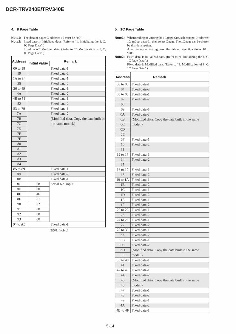
5-14
DCR-TRV240E/TRV340E
4. 8 Page Table
Note1: The data of page: 0, address: 10 must be “00”.Note2: Fixed data-1: Initialized data. (Refer to “1. Initializing the 8, C,
1C Page Data”.)Fixed data-2: Modified data. (Refer to “2. Modification of 8, C,1C Page Data”.)
Table. 5-1-8.
5. 1C Page Table
Note1: When reading or writing the 1C page data, select page: 0, address:10, and set data: 01, then select C page. The 1C page can be chosenby this data setting.After reading or writing, reset the data of page: 0, address: 10 to“00”.
Note2: Fixed data-1: Initialized data. (Refer to “1. Initializing the 8, C,1C Page Data”.)Fixed data-2: Modified data. (Refer to “2. Modification of 8, C,1C Page Data”.)00 to 18
19
1A to 34
35
36 to 49
4A
4B to 51
52
53 to 79
7A
7B
7C
7D
7E
7F
80
81
82
83
84
85 to 89
8A
8B
8C
8D
8E
8F
90
91
92
93
94 to A3
08
00
46
01
02
00
00
00
Fixed data-1
Fixed data-2
Fixed data-1
Fixed data-2
Fixed data-1
Fixed data-2
Fixed data-1
Fixed data-2
Fixed data-1
Fixed data-2
(Modified data. Copy the data built in
the same model.)
Fixed data-1
Fixed data-2
Fixed data-1
Serial No. input
Fixed data-1
Address RemarkInitial value
00 to 03
04
05 to 06
07
08
09
0A
0B
0C
0D
0E
0F
10
11
12 to 13
14
15
16 to 17
18
19 to 1A
1B
1C
1D
1E
1F
20 to 22
23
24 to 26
27
28 to 39
3A
3B
3C
3D
3E
3F to 40
41
42 to 43
44
45
46
47
48
49
4A
4B to 4F
Fixed data-1
Fixed data-2
Fixed data-1
Fixed data-2
Fixed data-1
Fixed data-2
(Modified data. Copy the data built in the same
model.)
Fixed data-1
Fixed data-2
Fixed data-1
Fixed data-2
Fixed data-1
Fixed data-2
Fixed data-1
Fixed data-2
Fixed data-1
Fixed data-2
Fixed data-1
Fixed data-2
Fixed data-1
Fixed data-2
Fixed data-1
Fixed data-2
Fixed data-1
Fixed data-2
Fixed data-1
Fixed data-2
(Modified data. Copy the data built in the same
model.)
Fixed data-1
Fixed data-2
Fixed data-1
Fixed data-2
(Modified data. Copy the data built in the same
model.)
Fixed data-1
Fixed data-2
Fixed data-1
Fixed data-2
Fixed data-1
Address Remark

5-15
DCR-TRV240E/TRV340E
Table. 5-1-9.
50
51 to 55
56
57
58 to 5C
5D
5E
5F
60
61
62
63
64
65
66
67
68
69
6A
6B to 6C
6D
6E
6F
70
71
72
73
74
75
76
77
78
79
7A
7B
7C
7D
7E
7F
80
81
82
83 to 85
86
87
88
89
8A
8B
8C to 97
98
99 to 9E
9F
A0 to FF
Fixed data-2
Fixed data-1
Fixed data-2
Fixed data-1
Fixed data-2
Fixed data-1
Fixed data-2
Fixed data-1
Fixed data-2
(Modified data. Copy the data built in the same
model.)
Fixed data-1
Fixed data-2
Fixed data-1
Fixed data-2
(Modified data. Copy the data built in the same
model.)
Fixed data-1
Fixed data-2
Fixed data-1
Fixed data-2
Fixed data-1
Fixed data-2
(Modified data. Copy the data built in the same
model.)
Fixed data-1
Fixed data-2
(Modified data. Copy the data built in the same
model.)
Fixed data-1
Fixed data-2
Fixed data-1
Fixed data-2
(Modified data. Copy the data built in the same
model.)
Fixed data-1
Fixed data-2
Fixed data-1
Fixed data-2
Fixed data-1
Address Remark
1C page
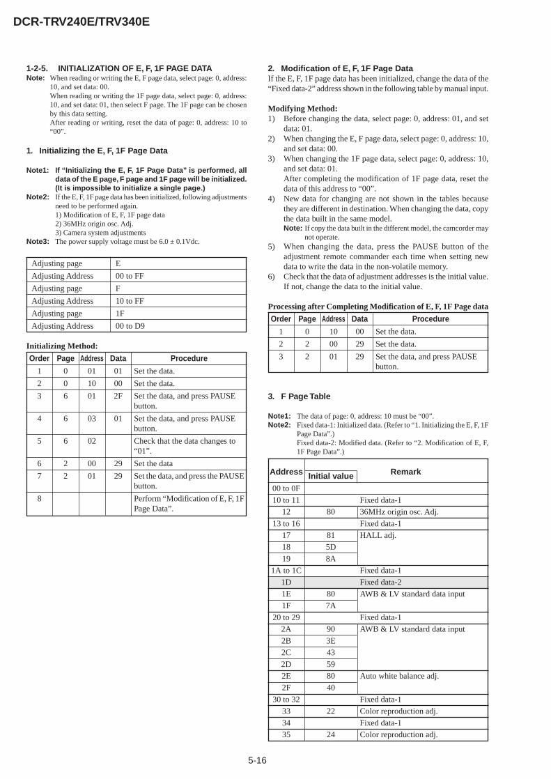
5-16
DCR-TRV240E/TRV340E
1-2-5. INITIALIZATION OF E, F, 1F PAGE DATANote: When reading or writing the E, F page data, select page: 0, address:
10, and set data: 00.When reading or writing the 1F page data, select page: 0, address:10, and set data: 01, then select F page. The 1F page can be chosenby this data setting.After reading or writing, reset the data of page: 0, address: 10 to“00”.
1. Initializing the E, F, 1F Page Data
Note1: If “Initializing the E, F, 1F Page Data” is performed, alldata of the E page, F page and 1F page will be initialized.(It is impossible to initialize a single page.)
Note2: If the E, F, 1F page data has been initialized, following adjustmentsneed to be performed again.1) Modification of E, F, 1F page data2) 36MHz origin osc. Adj.3) Camera system adjustments
Note3: The power supply voltage must be 6.0 ± 0.1Vdc.
Adjusting page E
Adjusting Address 00 to FF
Adjusting page F
Adjusting Address 10 to FF
Adjusting page 1F
Adjusting Address 00 to D9
Initializing Method:
Order Page Address Data Procedure
1 0 01 01 Set the data.
2 0 10 00 Set the data.
3 6 01 2F Set the data, and press PAUSEbutton.
4 6 03 01 Set the data, and press PAUSEbutton.
5 6 02 Check that the data changes to“01”.
6 2 00 29 Set the data
7 2 01 29 Set the data, and press the PAUSEbutton.
8 Perform “Modification of E, F, 1FPage Data”.
2. Modification of E, F, 1F Page DataIf the E, F, 1F page data has been initialized, change the data of the“Fixed data-2” address shown in the following table by manual input.
Modifying Method:1) Before changing the data, select page: 0, address: 01, and set
data: 01.2) When changing the E, F page data, select page: 0, address: 10,
and set data: 00.3) When changing the 1F page data, select page: 0, address: 10,
and set data: 01.After completing the modification of 1F page data, reset thedata of this address to “00”.
4) New data for changing are not shown in the tables becausethey are different in destination. When changing the data, copythe data built in the same model.Note: If copy the data built in the different model, the camcorder may
not operate.5) When changing the data, press the PAUSE button of the
adjustment remote commander each time when setting newdata to write the data in the non-volatile memory.
6) Check that the data of adjustment addresses is the initial value.If not, change the data to the initial value.
Processing after Completing Modification of E, F, 1F Page data
Order Page Address Data Procedure
1 0 10 00 Set the data.
2 2 00 29 Set the data.
3 2 01 29 Set the data, and press PAUSEbutton.
3. F Page Table
Note1: The data of page: 0, address: 10 must be “00”.Note2: Fixed data-1: Initialized data. (Refer to “1. Initializing the E, F, 1F
Page Data”.)Fixed data-2: Modified data. (Refer to “2. Modification of E, F,1F Page Data”.)
00 to 0F
10 to 11
12
13 to 16
17
18
19
1A to 1C
1D
1E
1F
20 to 29
2A
2B
2C
2D
2E
2F
30 to 32
33
34
35
80
81
5D
8A
80
7A
90
3E
43
59
80
40
22
24
Fixed data-1
36MHz origin osc. Adj.
Fixed data-1
HALL adj.
Fixed data-1
Fixed data-2
AWB & LV standard data input
Fixed data-1
AWB & LV standard data input
Auto white balance adj.
Fixed data-1
Color reproduction adj.
Fixed data-1
Color reproduction adj.
Address RemarkInitial value
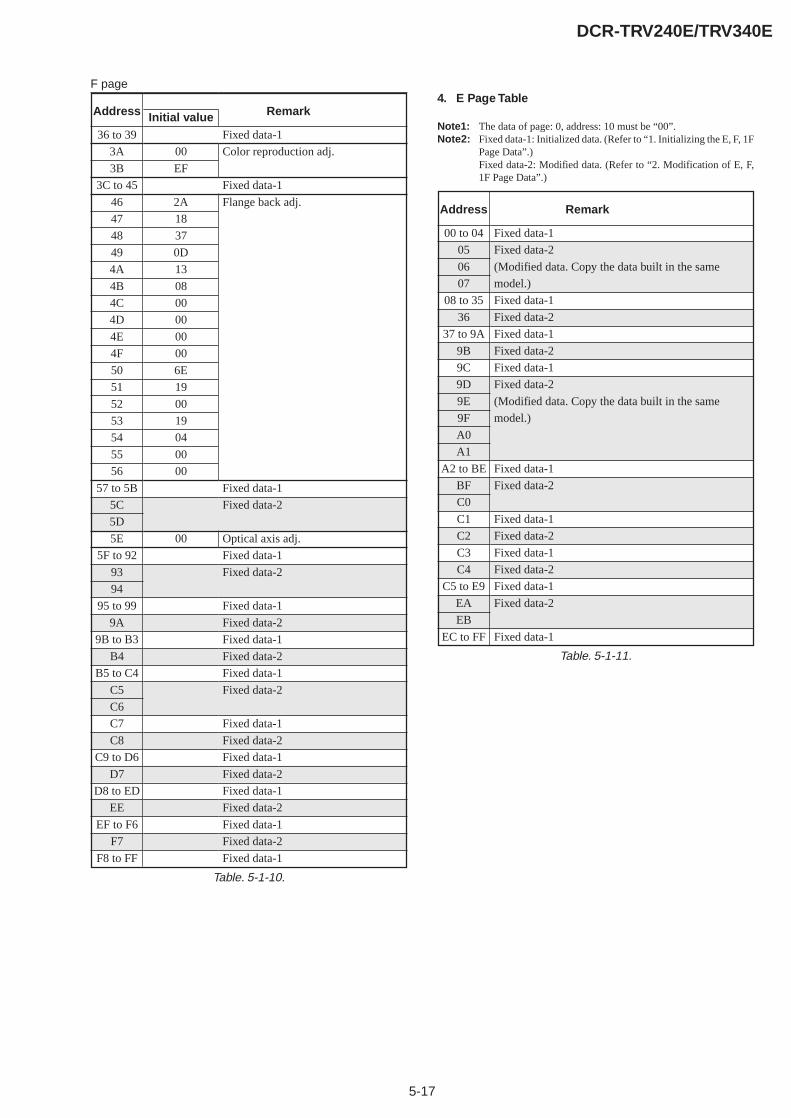
5-17
DCR-TRV240E/TRV340E
Table. 5-1-10.
36 to 39
3A
3B
3C to 45
46
47
48
49
4A
4B
4C
4D
4E
4F
50
51
52
53
54
55
56
57 to 5B
5C
5D
5E
5F to 92
93
94
95 to 99
9A
9B to B3
B4
B5 to C4
C5
C6
C7
C8
C9 to D6
D7
D8 to ED
EE
EF to F6
F7
F8 to FF
00
EF
2A
18
37
0D
13
08
00
00
00
00
6E
19
00
19
04
00
00
00
Fixed data-1
Color reproduction adj.
Fixed data-1
Flange back adj.
Fixed data-1
Fixed data-2
Optical axis adj.
Fixed data-1
Fixed data-2
Fixed data-1
Fixed data-2
Fixed data-1
Fixed data-2
Fixed data-1
Fixed data-2
Fixed data-1
Fixed data-2
Fixed data-1
Fixed data-2
Fixed data-1
Fixed data-2
Fixed data-1
Fixed data-2
Fixed data-1
Address RemarkInitial value
4. E Page Table
Note1: The data of page: 0, address: 10 must be “00”.Note2: Fixed data-1: Initialized data. (Refer to “1. Initializing the E, F, 1F
Page Data”.)Fixed data-2: Modified data. (Refer to “2. Modification of E, F,1F Page Data”.)
00 to 04
05
06
07
08 to 35
36
37 to 9A
9B
9C
9D
9E
9F
A0
A1
A2 to BE
BF
C0
C1
C2
C3
C4
C5 to E9
EA
EB
EC to FF
Fixed data-1
Fixed data-2
(Modified data. Copy the data built in the same
model.)
Fixed data-1
Fixed data-2
Fixed data-1
Fixed data-2
Fixed data-1
Fixed data-2
(Modified data. Copy the data built in the same
model.)
Fixed data-1
Fixed data-2
Fixed data-1
Fixed data-2
Fixed data-1
Fixed data-2
Fixed data-1
Fixed data-2
Fixed data-1
Address Remark
Table. 5-1-11.
F page

5-18
DCR-TRV240E/TRV340E
5. 1F Page Table
Note1: When reading or writing the 1F page data, select page: 0, address:10, and set data: 01, then select F page. The 1F page can be chosenby this data setting.After reading or writing, reset the data of page: 0, address: 10 to“00”.
Note2: Fixed data-1: Initialized data. (Refer to “1. Initializing the E, F, 1FPage Data”.)Fixed data-2: Modified data. (Refer to “2. Modification of E, F,1F Page Data”.)
Table. 5-1-12.
00 to 07
08
09
0A to 51
52
53 to 64
65
66
67 to 6B
6C
6D
6E
6F
70
71
72 to 7F
80
81 to 89
8A
8B to D8
D9
Fixed data-1
Fixed data-2
Fixed data-1
Fixed data-2
Fixed data-1
Fixed data-2
Fixed data-1
Fixed data-2
(Modified data. Copy the data built in the same
model.)
Fixed data-1
Fixed data-2
Fixed data-1
Fixed data-2
Fixed data-1
Fixed data-2
Address Remark

5-19
DCR-TRV240E/TRV340E
1-3. CAMERA SYSTEM ADJUSTMENTSBefore perform the camera system adjustments, check that thespecified values of “VIDEO SYSTEM ADJUSTMENTS” aresatisfied.And check that the data of page: 0, address: 10 is “00”. If not, setdata: 00 to this address.
1. HALL Adjustment
For detecting the position of the lens iris, adjust AMP gain andoffset.
Subject Not required
Measurement Point Display data of page 1 (Note1)
Measuring Instrument Adjustment remote commander
Adjustment Page F
Adjustment Address 17, 18, 19
Specified Value 1 89 to 8D
Specified Value 2 15 to 19
Note1: Displayed data of page 1 of the adjustment remote commander.1 : 00 : XX
IRIS display dataNote2: The data of page: 0, address: 10 must be “00”.
Switch setting:POWER .................................................................. CAMERA
Adjusting method:
Order Page Address Data Procedure
1 0 01 01 Set the data.
2 6 94 8B Set the data.
3 6 95 17 Set the data.
4 6 01 6D Set the data, and press PAUSEbutton.
5 6 02 Check that the data changes to“01”. (Note3)
6 6 01 00 Set the data, and press PAUSEbutton.
Note3: The adjustment data will be automatically input to page: F, address:17, 18, 19.
Checking method:
Order Page Address Data Procedure
1 0 03 03 Set the data.
2 6 01 01 Set the data, and press PAUSEbutton.
3 1 Check that the IRIS display data(Note1) satisfies the specifiedvalue 1.
4 6 01 03 Set the data, and press PAUSEbutton.
5 1 Check that the IRIS display data(Note1) satisfies the specifiedvalue 2.
Processing after Completing Adjustments:
Order Page Address Data Procedure
1 6 94 00 Set the data.
2 6 95 00 Set the data.
3 0 03 00 Set the data.
4 6 01 00 Set the data, and press PAUSEbutton.
5 0 01 00 Set the data.
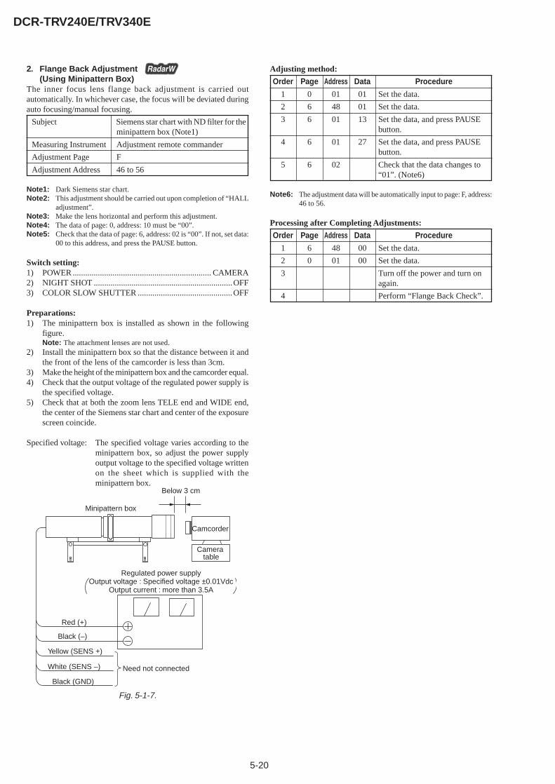
5-20
DCR-TRV240E/TRV340E
2. Flange Back Adjustment(Using Minipattern Box)
The inner focus lens flange back adjustment is carried outautomatically. In whichever case, the focus will be deviated duringauto focusing/manual focusing.
Subject Siemens star chart with ND filter for theminipattern box (Note1)
Measuring Instrument Adjustment remote commander
Adjustment Page F
Adjustment Address 46 to 56
Note1: Dark Siemens star chart.Note2: This adjustment should be carried out upon completion of “HALL
adjustment”.Note3: Make the lens horizontal and perform this adjustment.Note4: The data of page: 0, address: 10 must be “00”.Note5: Check that the data of page: 6, address: 02 is “00”. If not, set data:
00 to this address, and press the PAUSE button.
Switch setting:1) POWER .................................................................. CAMERA2) NIGHT SHOT ..................................................................OFF3) COLOR SLOW SHUTTER .............................................OFF
Preparations:1) The minipattern box is installed as shown in the following
figure.Note: The attachment lenses are not used.
2) Install the minipattern box so that the distance between it andthe front of the lens of the camcorder is less than 3cm.
3) Make the height of the minipattern box and the camcorder equal.4) Check that the output voltage of the regulated power supply is
the specified voltage.5) Check that at both the zoom lens TELE end and WIDE end,
the center of the Siemens star chart and center of the exposurescreen coincide.
Specified voltage: The specified voltage varies according to theminipattern box, so adjust the power supplyoutput voltage to the specified voltage writtenon the sheet which is supplied with theminipattern box.
Adjusting method:
Order Page Address Data Procedure
1 0 01 01 Set the data.
2 6 48 01 Set the data.
3 6 01 13 Set the data, and press PAUSEbutton.
4 6 01 27 Set the data, and press PAUSEbutton.
5 6 02 Check that the data changes to“01”. (Note6)
Note6: The adjustment data will be automatically input to page: F, address:46 to 56.
Processing after Completing Adjustments:
Order Page Address Data Procedure
1 6 48 00 Set the data.
2 0 01 00 Set the data.
3 Turn off the power and turn onagain.
4 Perform “Flange Back Check”.
Minipattern box
Below 3 cm
Camcorder
Camera table
Red (+)
Black (–)
Yellow (SENS +)
White (SENS –)
Black (GND)
Need not connected
Regulated power supplyOutput voltage : Specified voltage ±0.01Vdc
Output current : more than 3.5A
Fig. 5-1-7.

5-21
DCR-TRV240E/TRV340E
3. Flange Back Adjustment(Using Flange Back Adjustment Chart and SubjectMore Than 500m Away)
The inner focus lens flange back adjustment is carried outautomatically. In whichever case, the focus will be deviated duringauto focusing/manual focusing.
3-1. Flange Back Adjustment (1)
Subject Flange back adjustment chart(2.0 m from the front of the protectionglass) (Luminance: 350 ± 50 lux)
Measuring Instrument Adjustment remote commander
Adjustment Page F
Adjustment Address 46 to 56
Note1: This adjustment should be carried out upon completion of “HALLadjustment”.
Note2: Make the lens horizontal and perform this adjustment.Note3: The data of page: 0, address: 10 must be “00”.Note4: Check that the data of page: 6, address: 02 is “00”. If not, set data:
00 to this address, and press the PAUSE button.
Switch setting:1) POWER .................................................................. CAMERA2) NIGHT SHOT .................................................................. OFF3) COLOR SLOW SHUTTER .............................................OFF
Adjusting method:
Order Page Address Data Procedure
1 0 01 01 Set the data.
2 6 48 01 Set the data.
3 6 01 13 Set the data, and press PAUSEbutton.
4 6 01 15 Set the data, and press PAUSEbutton.
5 6 02 Check that the data changes to“01”. (Note5)
Note5: The adjustment data will be automatically input to page: F, address:46 to 56.
Processing after Completing Adjustments:
Order Page Address Data Procedure
1 Turn off the power and turn onagain.
2 Perform “Flange Back Adjustment(2)”
3-2. Flange Back Adjustment (2)Perform this adjustment after performing “Flange Back Adjustment(1)”.
Subject Subject more than 500m away(Subjects with clear contrast such asbuildings, etc.)
Measurement Point Check operation on TV monitor
Measuring Instrument
Adjustment Page F
Adjustment Address 46 to 56
Note1: Make the lens horizontal and perform this adjustment.Note2: The data of page: 0, address: 10 must be “00”.Note3: Check that the data of page: 6, address: 02 is “00”. If not, set data:
00 to this address, and press the PAUSE button.
Switch setting:1) POWER .................................................................. CAMERA2) NIGHT SHOT .................................................................. OFF3) COLOR SLOW SHUTTER .............................................OFF
Preparations:1) Set the zoom lens to the TELE end and expose a subject that is
more than 500m away (subject with clear contrast such asbuilding, etc.). (Nearby subjects less than 500m away shouldnot be in the screen.)
Adjusting method:
Order Page Address Data Procedure
1 0 01 01 Set the data.
2 6 48 01 Set the data.
3 6 01 13 Set the data, and press PAUSEbutton.
4 Place a ND filter on the lens sothat the optimum image is obtain.
5 6 01 29 Set the data, and press PAUSEbutton.
6 6 02 Check that the data changes to“01”. (Note4)
Note4: The adjustment data will be automatically input to page: F, address:46 to 56.
Processing after Completing Adjustments:
Order Page Address Data Procedure
1 6 48 00 Set the data.
2 0 01 00 Set the data.
3 Turn off the power and turn onagain.
4 Perform “Flange Back Check”.
5-22
DCR-TRV240E/TRV340E
4. Flange Back Check
Subject Siemens star(2.0m from the front of the lens)(Luminance : approx. 200 lux)
Measurement Point Check operation on TV monitor
Measuring Instrument
Specified Value Focused at the TELE end and WIDEend.
Note: The data of page: 0, address: 10 must be “00”.
Switch setting:1) POWER .................................................................. CAMERA2) NIGHT SHOT ..................................................................OFF3) COLOR SLOW SHUTTER .............................................OFF
Note: When the auto focus is ON, the lens can be checked if it is focusedor not by observing the data on the page 1 of the adjustment remotecommander.1) Select page: 0, address: 03, and set data: 0F.2) Page 1 shows the state of the focus.
1 : 00 : XXOdd: FocusedEven: Unfocused
Checking method:1) Select page: 6, address: 40, and set data: 01.2) Select page: 6, address: 41, and set data: 01.3) Place the Siemens star 2.0m from the front of the lens.4) To open the IRIS, decrease the luminous intensity to the
Siemens star up to a point before noise appear on the image.5) Shoot the Siemens star with the zoom TELE end.6) Turn on the auto focus.7) Check that the lens is focused (Note).8) Select page: 6, address: 21, and set data: 10.9) Shoot the Siemens star with the zoom WIDE end.10) Observe the TV monitor and check that the lens is focused.
Processing after Completing Adjustments:1) Select page: 6, address: 21, and set data: 00.2) Select page: 6, address: 40, and set data: 00.3) Select page: 6, address: 41, and set data: 00.4) Select page: 0, address: 03, and set data: 00.
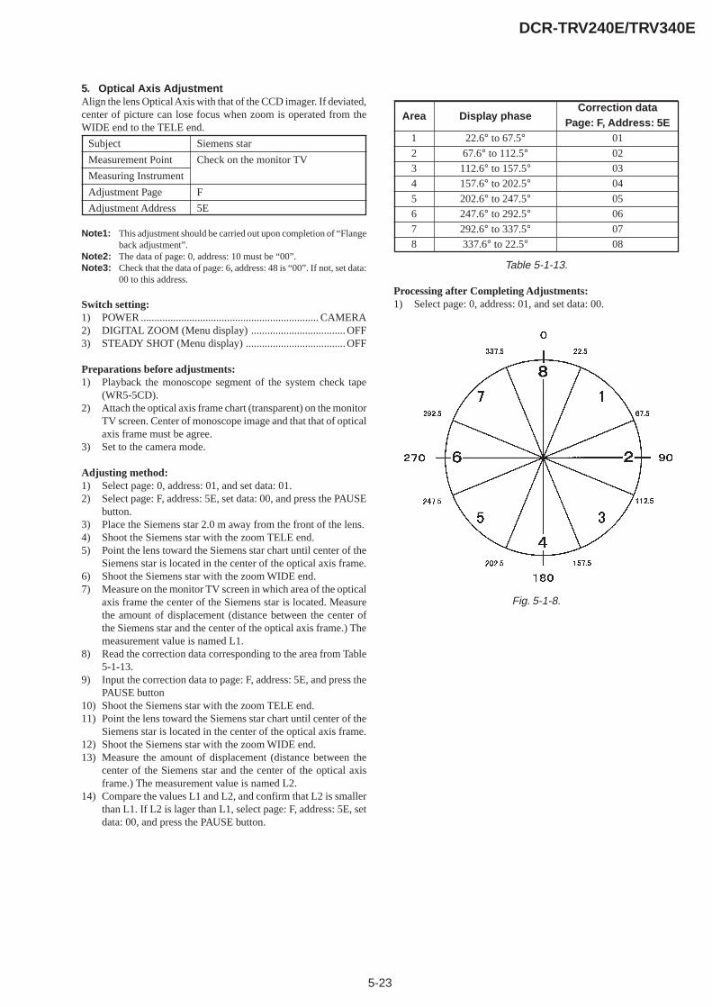
5-23
DCR-TRV240E/TRV340E
5. Optical Axis AdjustmentAlign the lens Optical Axis with that of the CCD imager. If deviated,center of picture can lose focus when zoom is operated from theWIDE end to the TELE end.
Subject Siemens star
Measurement Point Check on the monitor TV
Measuring Instrument
Adjustment Page F
Adjustment Address 5E
Note1: This adjustment should be carried out upon completion of “Flangeback adjustment”.
Note2: The data of page: 0, address: 10 must be “00”.Note3: Check that the data of page: 6, address: 48 is “00”. If not, set data:
00 to this address.
Switch setting:1) POWER .................................................................. CAMERA2) DIGITAL ZOOM (Menu display) ................................... OFF3) STEADY SHOT (Menu display) .....................................OFF
Preparations before adjustments:1) Playback the monoscope segment of the system check tape
(WR5-5CD).2) Attach the optical axis frame chart (transparent) on the monitor
TV screen. Center of monoscope image and that that of opticalaxis frame must be agree.
3) Set to the camera mode.
Adjusting method:1) Select page: 0, address: 01, and set data: 01.2) Select page: F, address: 5E, set data: 00, and press the PAUSE
button.3) Place the Siemens star 2.0 m away from the front of the lens.4) Shoot the Siemens star with the zoom TELE end.5) Point the lens toward the Siemens star chart until center of the
Siemens star is located in the center of the optical axis frame.6) Shoot the Siemens star with the zoom WIDE end.7) Measure on the monitor TV screen in which area of the optical
axis frame the center of the Siemens star is located. Measurethe amount of displacement (distance between the center ofthe Siemens star and the center of the optical axis frame.) Themeasurement value is named L1.
8) Read the correction data corresponding to the area from Table5-1-13.
9) Input the correction data to page: F, address: 5E, and press thePAUSE button
10) Shoot the Siemens star with the zoom TELE end.11) Point the lens toward the Siemens star chart until center of the
Siemens star is located in the center of the optical axis frame.12) Shoot the Siemens star with the zoom WIDE end.13) Measure the amount of displacement (distance between the
center of the Siemens star and the center of the optical axisframe.) The measurement value is named L2.
14) Compare the values L1 and L2, and confirm that L2 is smallerthan L1. If L2 is lager than L1, select page: F, address: 5E, setdata: 00, and press the PAUSE button.
Table 5-1-13.
Processing after Completing Adjustments:1) Select page: 0, address: 01, and set data: 00.
Area
1
2
3
4
5
6
7
8
Display phase
22.6° to 67.5°67.6° to 112.5°
112.6° to 157.5°157.6° to 202.5°202.6° to 247.5°247.6° to 292.5°292.6° to 337.5°337.6° to 22.5°
Correction dataPage: F, Address: 5E
01
02
03
04
05
06
07
08
Fig. 5-1-8.
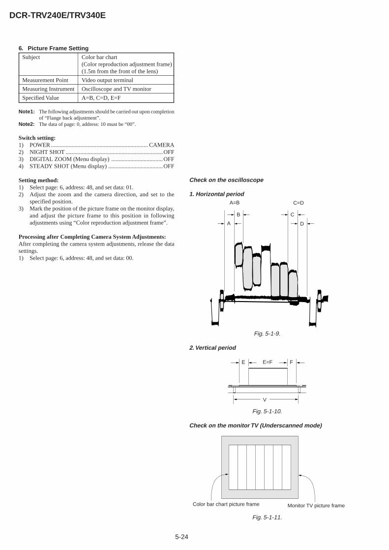
5-24
DCR-TRV240E/TRV340E
6. Picture Frame Setting
Subject Color bar chart(Color reproduction adjustment frame)(1.5m from the front of the lens)
Measurement Point Video output terminal
Measuring Instrument Oscilloscope and TV monitor
Specified Value A=B, C=D, E=F
Note1: The following adjustments should be carried out upon completionof “Flange back adjustment”.
Note2: The data of page: 0, address: 10 must be “00”.
Switch setting:1) POWER .................................................................. CAMERA2) NIGHT SHOT ..................................................................OFF3) DIGITAL ZOOM (Menu display) ...................................OFF4) STEADY SHOT (Menu display) .....................................OFF
Setting method:1) Select page: 6, address: 48, and set data: 01.2) Adjust the zoom and the camera direction, and set to the
specified position.3) Mark the position of the picture frame on the monitor display,
and adjust the picture frame to this position in followingadjustments using “Color reproduction adjustment frame”.
Processing after Completing Camera System Adjustments:After completing the camera system adjustments, release the datasettings.1) Select page: 6, address: 48, and set data: 00.
Check on the oscilloscope
1. Horizontal period
Fig. 5-1-9.
2. Vertical period
Fig. 5-1-10.
Check on the monitor TV (Underscanned mode)
Fig. 5-1-11.
A=B C=D
A
B C
D
E=F
V
E F
Color bar chart picture frame Monitor TV picture frame

5-25
DCR-TRV240E/TRV340E
7. Color Reproduction AdjustmentAdjust the color Separation matrix coefficient so that proper colorreproduction is produced.
Subject Color bar chart(Color reproduction adjustment frame)
Measurement Point Video output terminal
Measuring Instrument Vectorscope
Adjustment Page F
Adjustment Address 33, 35, 3A, 3B
Specified Value All color luminance points should settlewithin each color reproduction frame.
Note: The data of page: 0, address: 10 must be “00”.
Switch setting:1) POWER .................................................................. CAMERA2) NIGHT SHOT .................................................................. OFF3) DIGITAL ZOOM (Menu display) ................................... OFF4) STEADY SHOT (Menu display) .....................................OFF
Adjusting method:1) Select page: 0, address: 01, and set data: 01.2) Select page: 6, address: 48, and set data: 01.3) Select page: 6, address: 9D, set data: 2B.4) Select page: 6, address: 01, set data: 3D, and press the PAUSE
button.5) Select page: F, address: D0, set data: B7, and press the PAUSE
button.6) Adjust the GAIN and PHASE of the vectorscope, and adjust
the burst luminance point to the burst position of the colorreproduction frame.
7) Change the data of page: F, address: 33, 35, 3A, 3B, settle eachcolor luminance point in each color reproduction frame.Note: Be sure to press the PAUSE button of the adjustment remote
commander before changing the addresses. If not, the new datawill not be written to the memory.
Processing after Completing Adjustments:1) Select page: 6, address: 01, set data: 00, and press the PAUSE
button.2) Select page: 6, address: 48, and set data: 00.3) Select page: 6, address: 9D, and set data: 00.4) Select page: 0, address: 01, and set data: 00.
8. Auto White Balance & LV Standard Data InputAdjust the white balance reference at 3200K, and adjust the normalcoefficient of the light value.
Subject Clear chart(Color reproduction adjustment frame)
Measurement Point Display data of page 1 (Note5)
Measuring Instrument Adjustment remote commander
Adjustment Page F
Adjustment Address 1E, 1F, 2A to 2D
Specified Value 0FF0 to 1010
Note1: This adjustment should be carried out upon completion of “Colorreproduction adjustments”.
Note2: After the power is turned on, this adjustment can be done onlyonce.
Note3: The data of page: 0, address: 10 must be “00”.Note4: Check that the data of page: 6, address: 02 is “00”. If not, set data:
00 to this address, and press the PAUSE button.Note5: Displayed data of page 1 of the adjustment remote commander.
1 : XX : XXDisplay data
Switch setting:1) POWER .................................................................. CAMERA2) NIGHT SHOT .................................................................. OFF3) DIGITAL ZOOM (Menu display) ...................................OFF4) STEADY SHOT (Menu display) .....................................OFF
Adjusting method:
Order Page Address Data Procedure
1 0 01 01 Set the data.
2 6 48 01 Set the data.
3 6 16 02 Set the data.
4 Wait for 2 sec.
5 6 01 11 Set the data, and press PAUSEbutton.
6 6 01 0D Set the data, and press PAUSEbutton.n
7 6 02 Check that the data changes to“01”. (Note6)
8 0 03 1E Set the data.
9 1 Check that the display data (Note5)satisfies the specified value.
Note6: The adjustment data will be automatically input to page: F, address:1E, 1F and 2A to 2D.
Processing after Completing Adjustments
Order Page Address Data Procedure
1 6 01 00 Set the data, and press PAUSEbutton.
2 6 16 00 Set the data.
3 6 48 00 Set the data.
4 0 01 00 Set the data.
5 0 03 00 Set the data.
6 Perform “Auto White BalanceAdjustment”.
Burst position
Fig. 5-1-12.
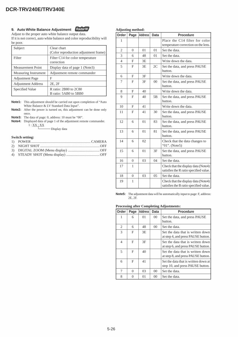
5-26
DCR-TRV240E/TRV340E
9. Auto White Balance AdjustmentAdjust to the proper auto white balance output data.If it is not correct, auto white balance and color reproducibility willbe poor.
Subject Clear chart(Color reproduction adjustment frame)
Filter Filter C14 for color temperaturecorrection
Measurement Point Display data of page 1 (Note3)
Measuring Instrument Adjustment remote commander
Adjustment Page F
Adjustment Address 2E, 2F
Specified Value R ratio: 2B80 to 2C80B ratio: 5AB0 to 5BB0
Note1: This adjustment should be carried out upon completion of “AutoWhite Balance & LV Standard Data Input”.
Note2: After the power is turned on, this adjustment can be done onlyonce.
Note3: The data of page: 0, address: 10 must be “00”.Note4: Displayed data of page 1 of the adjustment remote commander.
1 : XX : XXDisplay data
Switch setting:1) POWER .................................................................. CAMERA2) NIGHT SHOT ..................................................................OFF3) DIGITAL ZOOM (Menu display) ...................................OFF4) STEADY SHOT (Menu display) .....................................OFF
Adjusting method:
Order Page Address Data Procedure
1 Place the C14 filter for colortemperature correction on the lens.
2 0 01 01 Set the data.
3 6 48 01 Set the data.
4 F 3E Write down the data.
5 F 3E 2C Set the data, and press PAUSEbutton.
6 F 3F Write down the data.
7 F 3F 00 Set the data, and press PAUSEbutton.
8 F 40 Write down the data.
9 F 40 5B Set the data, and press PAUSEbutton.
10 F 41 Write down the data.
11 F 41 30 Set the data, and press PAUSEbutton.
12 6 01 83 Set the data, and press PAUSEbutton.
13 6 01 81 Set the data, and press PAUSEbutton.
14 6 02 Check that the data changes to“01”. (Note5)
15 6 01 3F Set the data, and press PAUSEbutton.
16 0 03 04 Set the data.
17 1 Check that the display data (Note4)satisfies the R ratio specified value.
18 0 03 05 Set the data.
19 1 Check that the display data (Note4)satisfies the B ratio specified value.
Note5: The adjustment data will be automatically input to page: F, address:2E, 2F.
Processing after Completing Adjustments:
Order Page Address Data Procedure
1 6 01 00 Set the data, and press PAUSEbutton.
2 6 48 00 Set the data.
3 F 3E Set the data that is written downat step 4, and press PAUSE button.
4 F 3F Set the data that is written downat step 6, and press PAUSE button.
5 F 40 Set the data that is written downat step 8, and press PAUSE button.
6 F 41 Set the data that is written down atstep 10, and press PAUSE button.
7 0 03 00 Set the data.
8 0 01 00 Set the data.

5-27
DCR-TRV240E/TRV340E
10. White Balance Check
Subject Clear chart(Color reproduction adjustment frame)
Filter Filter C14 for color temperaturecorrectionND filter 1.0 and 0.4 and 0.1
Measurement Point Video output terminal
Measuring Instrument Vectorscope
Specified Value Fig. 5-1-13. A to B
Note: The data of page: 0, address: 10 must be “00”.
Switch setting:1) POWER .................................................................. CAMERA2) NIGHT SHOT .................................................................. OFF3) DIGITAL ZOOM (Menu display) ................................... OFF4) STEADY SHOT (Menu display) .....................................OFF
Checking method:
Order Page Address Data Procedure
Indoor white balance check
1 Check that the lens is not coveredwith either filter.
2 6 48 01 Set the data.
3 6 01 0F Set the data, and press PAUSEbutton.
4 Check that the center of the whiteluminance point is within thecircle shown Fig. 5-1-13. A.
5 6 01 00 Set the data, and press PAUSEbutton.
Outdoor white balance check
6 Place the C14 filter on the lens.
7 6 01 3F Set the data, and press PAUSEbutton.
8 Check that the center of the whiteluminance point is within thecircle shown Fig. 5-1-13. B.
9 Remove the C14 filter.
LV data check
10 Place the ND filter 1.5 (1.0 + 0.1+ 0.4) on the lens.
11 6 01 00 Set the data, and press PAUSEbutton.
12 0 03 06 Set the data.
13 1 Check that the display data (Note)satisfies the specified value. Specified value: 8000 to 8BC0
Note: Displayed data of the adjustment remote commander.1 : XX : XX
Display data
Processing after Completing Adjustments
Order Page Address Data Procedure
1 6 01 00 Set the data, and press PAUSEbutton.
2 6 48 00 Set the data.
3 0 03 00 Set the data.
R-Y 2mm
B-Y
2mm
R-Y
B-Y
1.5mm
3mm
3mm
Fig. 5-1-13. (A)
Fig. 5-1-13. (B)
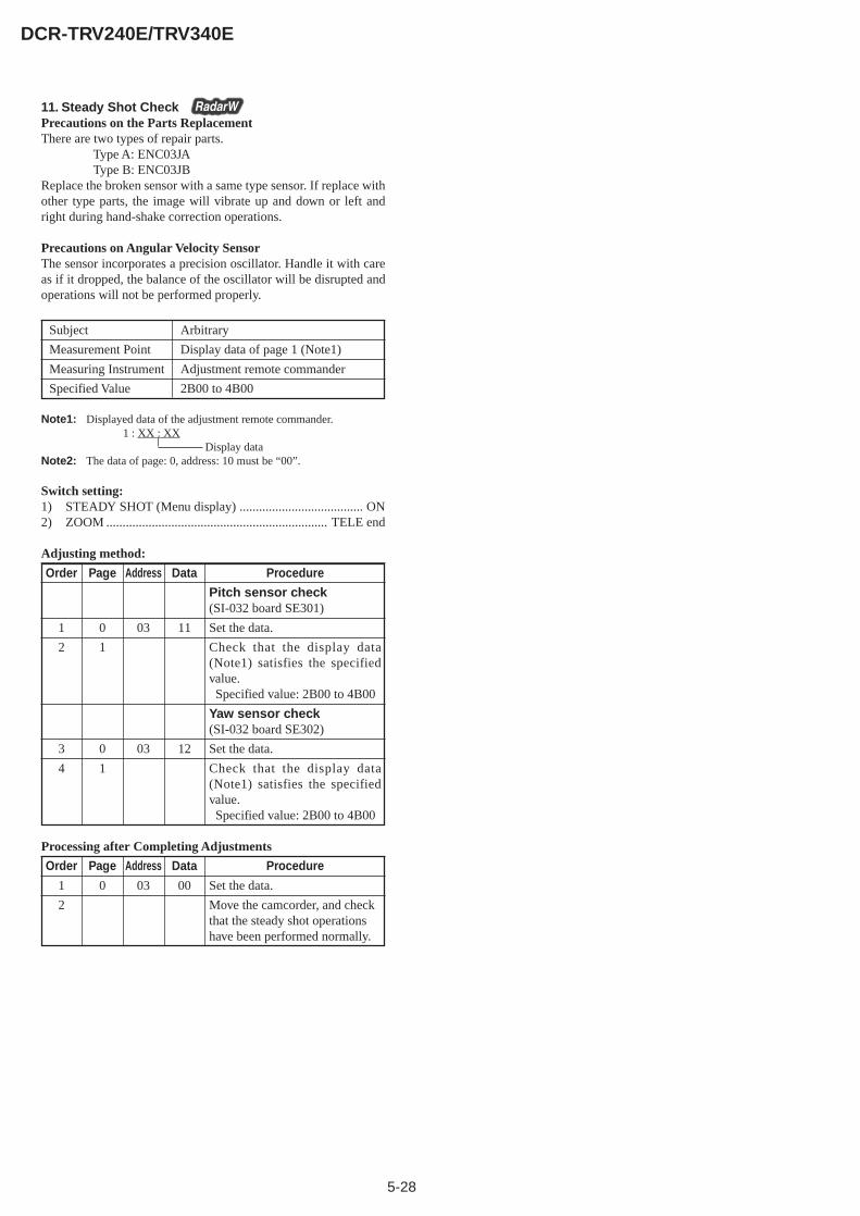
5-28
DCR-TRV240E/TRV340E
11. Steady Shot CheckPrecautions on the Parts ReplacementThere are two types of repair parts.
Type A: ENC03JAType B: ENC03JB
Replace the broken sensor with a same type sensor. If replace withother type parts, the image will vibrate up and down or left andright during hand-shake correction operations.
Precautions on Angular Velocity SensorThe sensor incorporates a precision oscillator. Handle it with careas if it dropped, the balance of the oscillator will be disrupted andoperations will not be performed properly.
Subject Arbitrary
Measurement Point Display data of page 1 (Note1)
Measuring Instrument Adjustment remote commander
Specified Value 2B00 to 4B00
Note1: Displayed data of the adjustment remote commander.1 : XX : XX
Display dataNote2: The data of page: 0, address: 10 must be “00”.
Switch setting:1) STEADY SHOT (Menu display) ...................................... ON2) ZOOM .................................................................... TELE end
Adjusting method:
Order Page Address Data Procedure
Pitch sensor check(SI-032 board SE301)
1 0 03 11 Set the data.
2 1 Check that the display data(Note1) satisfies the specifiedvalue. Specified value: 2B00 to 4B00
Yaw sensor check(SI-032 board SE302)
3 0 03 12 Set the data.
4 1 Check that the display data(Note1) satisfies the specifiedvalue. Specified value: 2B00 to 4B00
Processing after Completing Adjustments
Order Page Address Data Procedure
1 0 03 00 Set the data.
2 Move the camcorder, and checkthat the steady shot operationshave been performed normally.
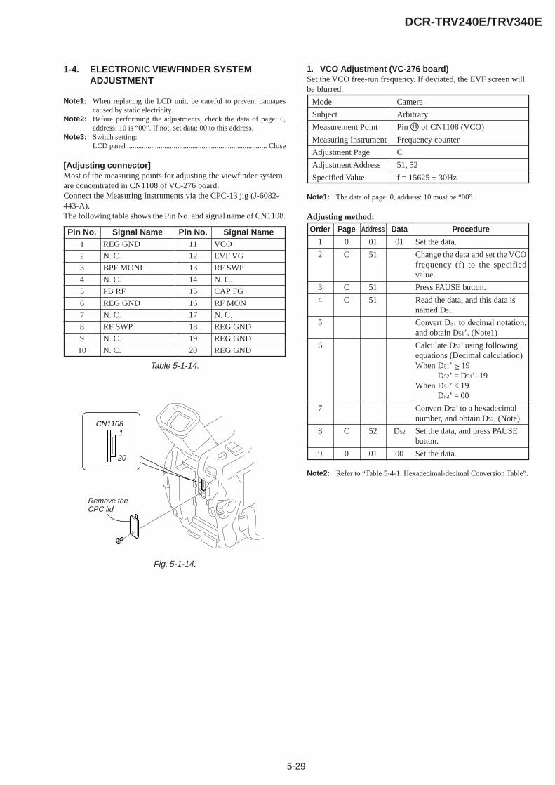
5-29
DCR-TRV240E/TRV340E
1-4. ELECTRONIC VIEWFINDER SYSTEMADJUSTMENT
Note1: When replacing the LCD unit, be careful to prevent damagescaused by static electricity.
Note2: Before performing the adjustments, check the data of page: 0,address: 10 is “00”. If not, set data: 00 to this address.
Note3: Switch setting:LCD panel ........................................................................... Close
[Adjusting connector]Most of the measuring points for adjusting the viewfinder systemare concentrated in CN1108 of VC-276 board.Connect the Measuring Instruments via the CPC-13 jig (J-6082-443-A).The following table shows the Pin No. and signal name of CN1108.
Table 5-1-14.
1. VCO Adjustment (VC-276 board)Set the VCO free-run frequency. If deviated, the EVF screen willbe blurred.
Mode Camera
Subject Arbitrary
Measurement Point Pin qa of CN1108 (VCO)
Measuring Instrument Frequency counter
Adjustment Page C
Adjustment Address 51, 52
Specified Value f = 15625 ± 30Hz
Note1: The data of page: 0, address: 10 must be “00”.
Adjusting method:
Order Page Address Data Procedure
1 0 01 01 Set the data.
2 C 51 Change the data and set the VCOfrequency (f) to the specifiedvalue.
3 C 51 Press PAUSE button.
4 C 51 Read the data, and this data isnamed D51.
5 Convert D51 to decimal notation,and obtain D51’. (Note1)
6 Calculate D52’ using followingequations (Decimal calculation)When D51’ 19
D52’ = D51’–19When D51’ < 19
D52’ = 00
7 Convert D52’ to a hexadecimalnumber, and obtain D52. (Note)
8 C 52 D52 Set the data, and press PAUSEbutton.
9 0 01 00 Set the data.
Note2: Refer to “Table 5-4-1. Hexadecimal-decimal Conversion Table”.
Pin No.1
2
3
4
5
6
7
8
9
10
Signal NameREG GND
N. C.
BPF MONI
N. C.
PB RF
REG GND
N. C.
RF SWP
N. C.
N. C.
Pin No.11
12
13
14
15
16
17
18
19
20
Signal NameVCO
EVF VG
RF SWP
N. C.
CAP FG
RF MON
N. C.
REG GND
REG GND
REG GND
Fig. 5-1-14.
CN1108
20
1
Remove the CPC lid
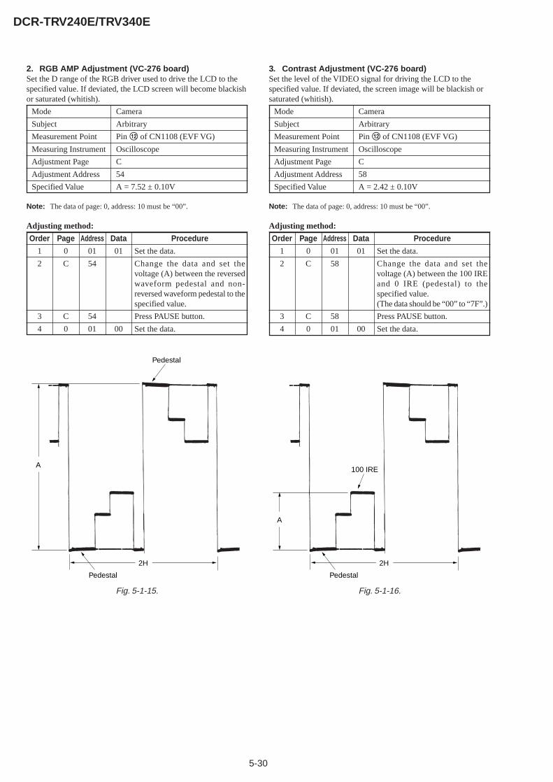
5-30
DCR-TRV240E/TRV340E
2. RGB AMP Adjustment (VC-276 board)Set the D range of the RGB driver used to drive the LCD to thespecified value. If deviated, the LCD screen will become blackishor saturated (whitish).
Mode Camera
Subject Arbitrary
Measurement Point Pin qs of CN1108 (EVF VG)
Measuring Instrument Oscilloscope
Adjustment Page C
Adjustment Address 54
Specified Value A = 7.52 ± 0.10V
Note: The data of page: 0, address: 10 must be “00”.
Adjusting method:
Order Page Address Data Procedure
1 0 01 01 Set the data.
2 C 54 Change the data and set thevoltage (A) between the reversedwaveform pedestal and non-reversed waveform pedestal to thespecified value.
3 C 54 Press PAUSE button.
4 0 01 00 Set the data.
3. Contrast Adjustment (VC-276 board)Set the level of the VIDEO signal for driving the LCD to thespecified value. If deviated, the screen image will be blackish orsaturated (whitish).
Mode Camera
Subject Arbitrary
Measurement Point Pin qs of CN1108 (EVF VG)
Measuring Instrument Oscilloscope
Adjustment Page C
Adjustment Address 58
Specified Value A = 2.42 ± 0.10V
Note: The data of page: 0, address: 10 must be “00”.
Adjusting method:
Order Page Address Data Procedure
1 0 01 01 Set the data.
2 C 58 Change the data and set thevoltage (A) between the 100 IREand 0 IRE (pedestal) to thespecified value.(The data should be “00” to “7F”.)
3 C 58 Press PAUSE button.
4 0 01 00 Set the data.
Pedestal
Pedestal
A
2H
100 IRE
Pedestal
A
2H
Fig. 5-1-15. Fig. 5-1-16.
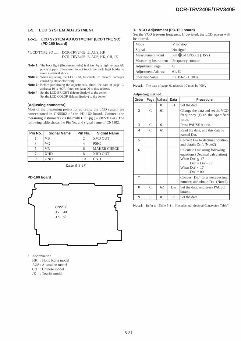
5-31
DCR-TRV240E/TRV340E
1-5. LCD SYSTEM ADJUSTMENT
1-5-1. LCD SYSTEM ADJUSTMETNT (LCD TYPE SO)(PD-160 board)
* LCD TYPE SO ........ DCR-TRV240E: E, AUS, HKDCR-TRV340E: E. AUS, HK, CH, JE
Note 1: The back light (fluorescent tube) is driven by a high voltage ACpower supply. Therefore, do not touch the back light holder toavoid electrical shock.
Note 2: When replacing the LCD unit, be careful to prevent damagescaused by static electricity.
Note 3: Before performing the adjustments, check the data of page: 0,address: 10 is “00”. If not, set data: 00 to this address.
Note 4: Set the LCD BRIGHT (Menu display) to the center.Set the LCD COLOR (Menu display) to the center.
[Adjusting connector]Most of the measuring points for adjusting the LCD system areconcentrated in CN5502 of the PD-160 board. Connect themeasuring instruments via the multi CPC jig (J-6082-311-A). Thefollowing table shows the Pin No. and signal name of CN5502.
Table 5-1-15.
1. VCO Adjustment (PD-160 board)Set the VCO free-run frequency. If deviated, the LCD screen willbe blurred.
Mode VTR stop
Signal No signal
Measurement Point Pin 8 of CN5502 (HSY)
Measuring Instrument Frequency counter
Adjustment Page C
Adjustment Address 61, 62
Specified Value f = 15625 ± 30Hz
Note1: The data of page: 0, address: 10 must be “00”.
Adjusting method:
Order Page Address Data Procedure
1 0 01 01 Set the data.
2 C 61 Change the data and set the VCOfrequency (f) to the specifiedvalue.
3 C 61 Press PAUSE button.
4 C 61 Read the data, and this data isnamed D61.
5 Convert D61 to decimal notation,and obtain D61’. (Note2)
6 Calculate D62’ using followingequations (Decimal calculation)When D61’ 17
D62’ = D61’– 17When D61’ < 17
D62’ = 00
7 Convert D62’ to a hexadecimalnumber, and obtain D62. (Note2)
8 C 62 D62 Set the data, and press PAUSEbutton.
9 0 01 00 Set the data.
Note2: Refer to “Table 5-4-1. Hexadecimal-decimal Conversion Table”.
109
1 2
CN5502
Pin No.1
3
5
7
9
Signal NameVB
VG
VR
XHD
GND
Pin No.2
4
6
8
10
Signal NameXVD OUT
PSIG
MAKER CHECK
XHD OUT
GND
PD-160 board
• AbbreviationHK : Hong Kong modelAUS : Australian modelCH : Chinese modelJE : Tourist model
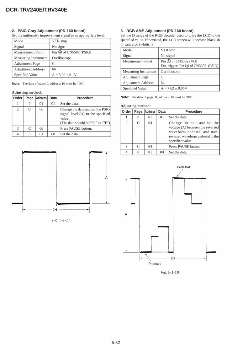
5-32
DCR-TRV240E/TRV340E
2. PSIG Gray Adjustment (PD-160 board)Set the uniformity improvement signal to an appropriate level.
Mode VTR stop
Signal No signal
Measurement Point Pin 4 of CN5502 (PSIG)
Measuring Instrument Oscilloscope
Adjustment Page C
Adjustment Address 66
Specified Value A = 5.00 ± 0.1V
Note: The data of page: 0, address: 10 must be “00”.
Adjusting method:
Order Page Address Data Procedure
1 0 01 01 Set the data.
2 C 66 Change the data and set the PSIGsignal level (A) to the specifiedvalue.(The data should be “00” to “7F”)
3 C 66 Press PAUSE button.
4 0 01 00 Set the data.
3. RGB AMP Adjustment (PD-160 board)Set the D range of the RGB decoder used to drive the LCD to thespecified value. If deviated, the LCD screen will become blackishor saturated (whitish).
Mode VTR stop
Signal No signal
Measurement Point Pin 3 of CN5502 (VG)Ext. trigger: Pin 4 of CN5502 (PSIG)
Measuring Instrument Oscilloscope
Adjustment Page C
Adjustment Address 64
Specified Value A = 7.62 ± 0.05V
Note: The data of page: 0, address: 10 must be “00”.
Adjusting method:
Order Page Address Data Procedure
1 0 01 01 Set the data.
2 C 64 Change the data and set thevoltage (A) between the reversedwaveform pedestal and non-reversed waveform pedestal to thespecified value.
3 C 64 Press PAUSE button.
4 0 01 00 Set the data.
Fig. 5-1-17.
A
2H
Pedestal
Pedestal
A
2H
Fig. 5-1-18.
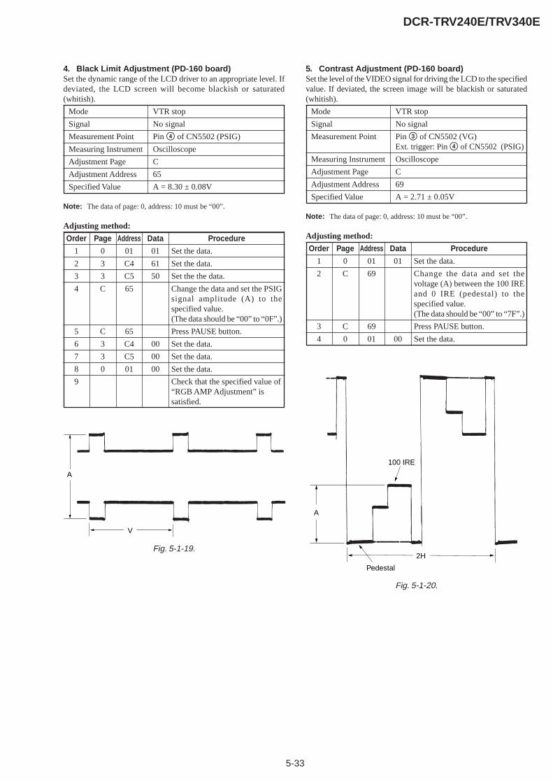
5-33
DCR-TRV240E/TRV340E
4. Black Limit Adjustment (PD-160 board)Set the dynamic range of the LCD driver to an appropriate level. Ifdeviated, the LCD screen will become blackish or saturated(whitish).
Mode VTR stop
Signal No signal
Measurement Point Pin 4 of CN5502 (PSIG)
Measuring Instrument Oscilloscope
Adjustment Page C
Adjustment Address 65
Specified Value A = 8.30 ± 0.08V
Note: The data of page: 0, address: 10 must be “00”.
Adjusting method:
Order Page Address Data Procedure
1 0 01 01 Set the data.
2 3 C4 61 Set the data.
3 3 C5 50 Set the the data.
4 C 65 Change the data and set the PSIGsignal amplitude (A) to thespecified value.(The data should be “00” to “0F”.)
5 C 65 Press PAUSE button.
6 3 C4 00 Set the data.
7 3 C5 00 Set the data.
8 0 01 00 Set the data.
9 Check that the specified value of“RGB AMP Adjustment” issatisfied.
5. Contrast Adjustment (PD-160 board)Set the level of the VIDEO signal for driving the LCD to the specifiedvalue. If deviated, the screen image will be blackish or saturated(whitish).
Mode VTR stop
Signal No signal
Measurement Point Pin 3 of CN5502 (VG)Ext. trigger: Pin 4 of CN5502 (PSIG)
Measuring Instrument Oscilloscope
Adjustment Page C
Adjustment Address 69
Specified Value A = 2.71 ± 0.05V
Note: The data of page: 0, address: 10 must be “00”.
Adjusting method:
Order Page Address Data Procedure
1 0 01 01 Set the data.
2 C 69 Change the data and set thevoltage (A) between the 100 IREand 0 IRE (pedestal) to thespecified value.(The data should be “00” to “7F”.)
3 C 69 Press PAUSE button.
4 0 01 00 Set the data.
A
V
Fig. 5-1-19.
100 IRE
Pedestal
A
2H
Fig. 5-1-20.

5-34
DCR-TRV240E/TRV340E
6. Center Level Adjustment (PD-160 board)Set the video signal center level of LCD panel to an appropriatelevel.
Mode VTR stop
Signal No signal
Measurement Point Pin 3 of CN5502 (VG)
Measuring Instrument Digital voltmeter
Adjustment Page C
Adjustment Address 6A
Specified Value A = 7.00 ± 0.03Vdc
Note: The data of page: 0, address: 10 must be “00”.
Adjusting method:
Order Page Address Data Procedure
1 0 01 01 Set the data.
2 C 6A Change the data and set the DCvoltage (A) to the specified value.(The data should be “00” to “7F”.)
3 C 6A Press PAUSE button.
4 0 01 00 Set the data.
7. V-COM Adjustment (PD-160 board)Set the DC bias of the common electrode drive signal of LCD to thespecified value.If deviated, the LCD display will move, producing flicker andconspicuous vertical lines.
Mode VTR stop
Signal No signal
Measurement Point Check on LCD display
Measuring Instrument
Adjustment Page C
Adjustment Address 63
Specified Value The brightness difference between thesection A and section B is minimum.
Note1: This adjustment should be carried out upon completion of thefollowing adjustments.
RGB AMP AdjustmentBlack Limit AdjustmentContrast AdjustmentCenter Level Adjustment
Note2: The data of page: 0, address: 10 must be “00”.
Adjusting method:
Order Page Address Data Procedure
1 0 01 01 Set the data.
2 C 63 Change the data so that thebrightness of the section A andthat of the section B is equal.(The data should be “00” to “3F”.)
3 C 63 Subtract 2 from the data.
4 C 63 Press PAUSE button.
5 0 01 00 Set the data.
Fig. 5-1-21.
A
A
A
A
B
B
B
B
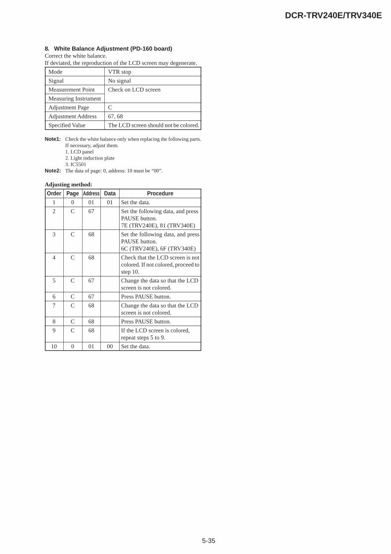
5-35
DCR-TRV240E/TRV340E
8. White Balance Adjustment (PD-160 board)Correct the white balance.If deviated, the reproduction of the LCD screen may degenerate.
Mode VTR stop
Signal No signal
Measurement Point Check on LCD screen
Measuring Instrument
Adjustment Page C
Adjustment Address 67, 68
Specified Value The LCD screen should not be colored.
Note1: Check the white balance only when replacing the following parts.If necessary, adjust them.1. LCD panel2. Light induction plate3. IC5501
Note2: The data of page: 0, address: 10 must be “00”.
Adjusting method:
Order Page Address Data Procedure
1 0 01 01 Set the data.
2 C 67 Set the following data, and pressPAUSE button.7E (TRV240E), 81 (TRV340E)
3 C 68 Set the following data, and pressPAUSE button.6C (TRV240E), 6F (TRV340E)
4 C 68 Check that the LCD screen is notcolored. If not colored, proceed tostep 10.
5 C 67 Change the data so that the LCDscreen is not colored.
6 C 67 Press PAUSE button.
7 C 68 Change the data so that the LCDscreen is not colored.
8 C 68 Press PAUSE button.
9 C 68 If the LCD screen is colored,repeat steps 5 to 9.
10 0 01 00 Set the data.

5-36
DCR-TRV240E/TRV340E
1-5-2. LCD SYSTEM ADJUSTMETNT (LCD TYPE SH)(PD-156 board)
* LCD TYPE SH ........ DCR-TRV240E: AEP, UK, EE, NE, RUDCR-TRV340E: AEP, UK, EE, NE, RU
Note 1: The back light (fluorescent tube) is driven by a high voltage ACpower supply. Therefore, do not touch the back light holder toavoid electrical shock.
Note 2: When replacing the LCD unit, be careful to prevent damagescaused by static electricity.
Note 3: Before performing the adjustments, check the data of page: 0,address: 10 is “00”. If not, set data: 00 to this address.
Note 4: Set the LCD BRIGHT (Menu display) to the center.Set the LCD COLOR (Menu display) to the center.
[Adjusting connector]Most of the measuring points for adjusting the LCD system areconcentrated in CN5502 of the PD-156 board. Connect themeasuring instruments via the multi CPC jig (J-6082-311-A). Thefollowing table shows the Pin No. and signal name of CN5502.
Table 5-1-16.
1. VCO Adjustment (PD-156 board)Set the VCO free-run frequency. If deviated, the LCD screen willbe blurred.
Mode VTR stop
Signal No signal
Measurement Point Pin 8 of CN5502 (XHD OUT)
Measuring Instrument Frequency counter
Adjustment Page C
Adjustment Address 61, 62
Specified Value f = 15625 ± 30Hz
Note1: The data of page: 0, address: 10 must be “00”.
Adjusting method:
Order Page Address Data Procedure
1 0 01 01 Set the data.
2 C 61 Change the data and set the VCOfrequency (f) to the specifiedvalue.
3 C 61 Press PAUSE button.
4 C 61 Read the data, and this data isnamed D61.
5 Convert D61 to decimal notation,and obtain D61’. (Note2)
6 Calculate D62’ using followingequations (Decimal calculation)When D61’ 20
D62’ = D61’– 20When D61’ < 20
D62’ = 00
7 Convert D62’ to a hexadecimalnumber, and obtain D62. (Note2)
8 C 62 D62 Set the data, and press PAUSEbutton.
9 0 01 00 Set the data.
Note2: Refer to “Table 5-4-1. Hexadecimal-decimal Conversion Table”.109
1 2
CN5502
Pin No.1
3
5
7
9
Signal NameVB
VG
VR
C-SYNC/XHD
GND
Pin No.2
4
6
8
10
Signal NameXVD OUT
PANEL COM
PANEL ID
XHD OUT
GND
PD-156 board
• AbbreviationEE : East European modelNE : North European modelRU : Russian model
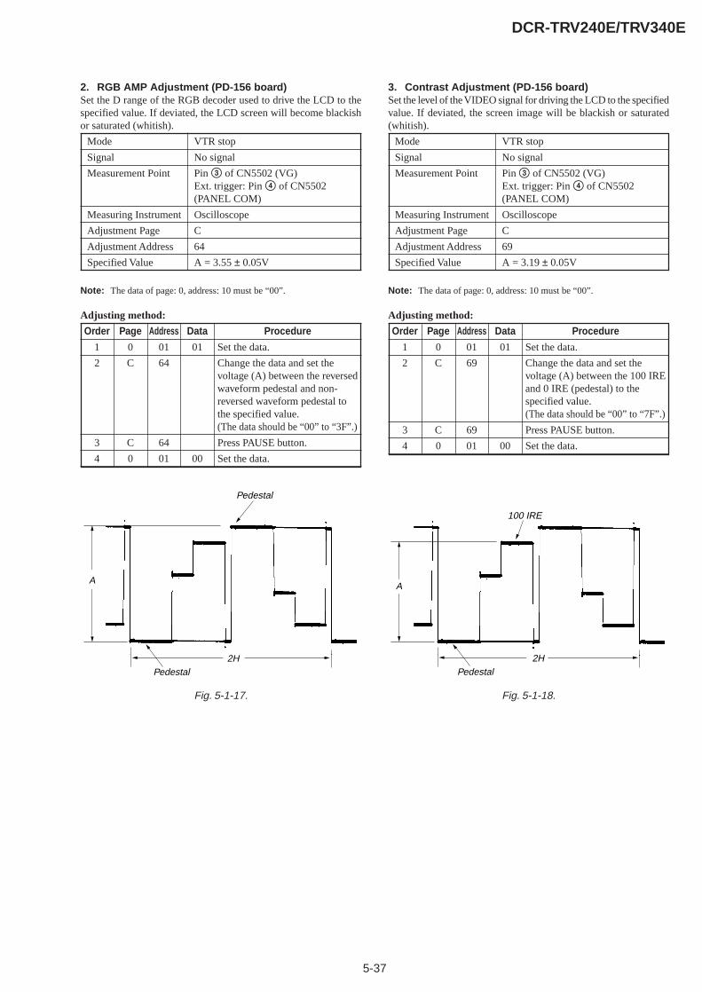
5-37
DCR-TRV240E/TRV340E
Fig. 5-1-17.
Pedestal
Pedestal
A
2H
100 IRE
Pedestal
A
2H
Fig. 5-1-18.
2. RGB AMP Adjustment (PD-156 board)Set the D range of the RGB decoder used to drive the LCD to thespecified value. If deviated, the LCD screen will become blackishor saturated (whitish).
Mode VTR stop
Signal No signal
Measurement Point Pin 3 of CN5502 (VG)Ext. trigger: Pin 4 of CN5502(PANEL COM)
Measuring Instrument Oscilloscope
Adjustment Page C
Adjustment Address 64
Specified Value A = 3.55 ± 0.05V
Note: The data of page: 0, address: 10 must be “00”.
Adjusting method:
Order Page Address Data Procedure
1 0 01 01 Set the data.
2 C 64 Change the data and set thevoltage (A) between the reversedwaveform pedestal and non-reversed waveform pedestal tothe specified value.(The data should be “00” to “3F”.)
3 C 64 Press PAUSE button.
4 0 01 00 Set the data.
3. Contrast Adjustment (PD-156 board)Set the level of the VIDEO signal for driving the LCD to the specifiedvalue. If deviated, the screen image will be blackish or saturated(whitish).
Mode VTR stop
Signal No signal
Measurement Point Pin 3 of CN5502 (VG)Ext. trigger: Pin 4 of CN5502(PANEL COM)
Measuring Instrument Oscilloscope
Adjustment Page C
Adjustment Address 69
Specified Value A = 3.19 ± 0.05V
Note: The data of page: 0, address: 10 must be “00”.
Adjusting method:
Order Page Address Data Procedure
1 0 01 01 Set the data.
2 C 69 Change the data and set thevoltage (A) between the 100 IREand 0 IRE (pedestal) to thespecified value.(The data should be “00” to “7F”.)
3 C 69 Press PAUSE button.
4 0 01 00 Set the data.
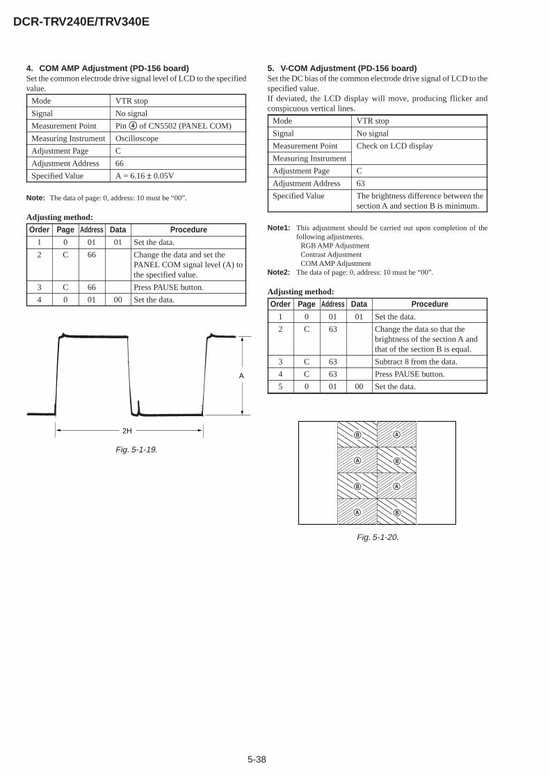
5-38
DCR-TRV240E/TRV340E
Fig. 5-1-19.
Fig. 5-1-20.
A
A
A
A
B
B
B
B
A
2H
4. COM AMP Adjustment (PD-156 board)Set the common electrode drive signal level of LCD to the specifiedvalue.
Mode VTR stop
Signal No signal
Measurement Point Pin 4 of CN5502 (PANEL COM)
Measuring Instrument Oscilloscope
Adjustment Page C
Adjustment Address 66
Specified Value A = 6.16 ± 0.05V
Note: The data of page: 0, address: 10 must be “00”.
Adjusting method:
Order Page Address Data Procedure
1 0 01 01 Set the data.
2 C 66 Change the data and set thePANEL COM signal level (A) tothe specified value.
3 C 66 Press PAUSE button.
4 0 01 00 Set the data.
5. V-COM Adjustment (PD-156 board)Set the DC bias of the common electrode drive signal of LCD to thespecified value.If deviated, the LCD display will move, producing flicker andconspicuous vertical lines.
Mode VTR stop
Signal No signal
Measurement Point Check on LCD display
Measuring Instrument
Adjustment Page C
Adjustment Address 63
Specified Value The brightness difference between thesection A and section B is minimum.
Note1: This adjustment should be carried out upon completion of thefollowing adjustments.
RGB AMP AdjustmentContrast AdjustmentCOM AMP Adjustment
Note2: The data of page: 0, address: 10 must be “00”.
Adjusting method:
Order Page Address Data Procedure
1 0 01 01 Set the data.
2 C 63 Change the data so that thebrightness of the section A andthat of the section B is equal.
3 C 63 Subtract 8 from the data.
4 C 63 Press PAUSE button.
5 0 01 00 Set the data.

5-39
DCR-TRV240E/TRV340E
6. White Balance Adjustment (PD-156 board)Correct the white balance.If deviated, the reproduction of the LCD screen may degenerate.
Mode VTR stop
Signal No signal
Measurement Point Check on LCD screen
Measuring Instrument
Adjustment Page C
Adjustment Address 67, 68
Specified Value The LCD screen should not be colored.
Note1: Check the white balance only when replacing the following parts.If necessary, adjust them.1. LCD panel2. Light induction plate3. IC5501
Note2: The data of page: 0, address: 10 must be “00”.
Adjusting method:
Order Page Address Data Procedure
1 0 01 01 Set the data.
2 C 67 84 Set the data, and press PAUSEbutton.
3 C 68 5F Set the data, and press PAUSEbutton.
4 C 68 Check that the LCD screen is notcolored. If not colored, proceedto step 10.
5 C 67 Change the data so that the LCDscreen is not colored.
6 C 67 Press PAUSE button.
7 C 68 Change the data so that the LCDscreen is not colored.
8 C 68 Press PAUSE button.
9 C 68 If the LCD screen is colored,repeat steps 5 to 9.
10 0 01 00 Set the data.
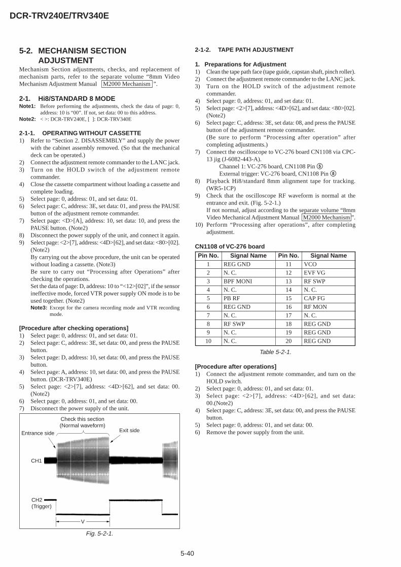
5-40
DCR-TRV240E/TRV340E
5-2. MECHANISM SECTIONADJUSTMENT
Mechanism Section adjustments, checks, and replacement ofmechanism parts, refer to the separate volume “8mm VideoMechanism Adjustment Manual M2000 Mechanism ”.
2-1. Hi8/STANDARD 8 MODENote1: Before performing the adjustments, check the data of page: 0,
address: 10 is “00”. If not, set data: 00 to this address.Note2: < >: DCR-TRV240E, [ ]: DCR-TRV340E
2-1-1. OPERATING WITHOUT CASSETTE1) Refer to “Section 2. DISASSEMBLY” and supply the power
with the cabinet assembly removed. (So that the mechanicaldeck can be operated.)
2) Connect the adjustment remote commander to the LANC jack.3) Turn on the HOLD switch of the adjustment remote
commander.4) Close the cassette compartment without loading a cassette and
complete loading.5) Select page: 0, address: 01, and set data: 01.6) Select page: C, address: 3E, set data: 01, and press the PAUSE
button of the adjustment remote commander.7) Select page: <D>[A], address: 10, set data: 10, and press the
PAUSE button. (Note2)8) Disconnect the power supply of the unit, and connect it again.9) Select page: <2>[7], address: <4D>[62], and set data: <80>[02].
(Note2)By carrying out the above procedure, the unit can be operatedwithout loading a cassette. (Note3)Be sure to carry out “Processing after Operations” afterchecking the operations.Set the data of page: D, address: 10 to “<12>[02]”, if the sensorineffective mode, forced VTR power supply ON mode is to beused together. (Note2)Note3: Except for the camera recording mode and VTR recording
mode.
[Procedure after checking operations]1) Select page: 0, address: 01, and set data: 01.2) Select page: C, address: 3E, set data: 00, and press the PAUSE
button.3) Select page: D, address: 10, set data: 00, and press the PAUSE
button.4) Select page: A, address: 10, set data: 00, and press the PAUSE
button. (DCR-TRV340E)5) Select page: <2>[7], address: <4D>[62], and set data: 00.
(Note2)6) Select page: 0, address: 01, and set data: 00.7) Disconnect the power supply of the unit.
Fig. 5-2-1.
2-1-2. TAPE PATH ADJUSTMENT
1. Preparations for Adjustment1) Clean the tape path face (tape guide, capstan shaft, pinch roller).2) Connect the adjustment remote commander to the LANC jack.3) Turn on the HOLD switch of the adjustment remote
commander.4) Select page: 0, address: 01, and set data: 01.5) Select page: <2>[7], address: <4D>[62], and set data: <80>[02].
(Note2)6) Select page: C, address: 3E, set data: 08, and press the PAUSE
button of the adjustment remote commander.(Be sure to perform “Processing after operation” aftercompleting adjustments.)
7) Connect the oscilloscope to VC-276 board CN1108 via CPC-13 jig (J-6082-443-A).
Channel 1: VC-276 board, CN1108 Pin 5External trigger: VC-276 board, CN1108 Pin 8
8) Playback Hi8/standard 8mm alignment tape for tracking.(WR5-1CP)
9) Check that the oscilloscope RF waveform is normal at theentrance and exit. (Fig. 5-2-1.)If not normal, adjust according to the separate volume “8mmVideo Mechanical Adjustment Manual M2000 Mechanism ”.
10) Perform “Processing after operations”, after completingadjustment.
CN1108 of VC-276 board
Table 5-2-1.
[Procedure after operations]1) Connect the adjustment remote commander, and turn on the
HOLD switch.2) Select page: 0, address: 01, and set data: 01.3) Select page: <2>[7], address: <4D>[62], and set data:
00.(Note2)4) Select page: C, address: 3E, set data: 00, and press the PAUSE
button.5) Select page: 0, address: 01, and set data: 00.6) Remove the power supply from the unit.
Pin No.1
2
3
4
5
6
7
8
9
10
Signal NameREG GND
N. C.
BPF MONI
N. C.
PB RF
REG GND
N. C.
RF SWP
N. C.
N. C.
Pin No.11
12
13
14
15
16
17
18
19
20
Signal NameVCO
EVF VG
RF SWP
N. C.
CAP FG
RF MON
N. C.
REG GND
REG GND
REG GND
CH1
Entrance side Exit side
Check this section(Normal waveform)
CH2(Trigger)
V

5-41
DCR-TRV240E/TRV340E
2-2. DIGITAL8 MODENote1: Before performing the adjustments, check the data of page: 0,
address: 10 is “00”. If not, set data: 00 to this address.Note2: < >: DCR-TRV240E, [ ]: DCR-TRV340E
2-2-1. HOW TO ENTER RECORD MODE WITHOUTCASSETTE
1) Connect the adjustment remote commander to the LANC jack.2) Turn the HOLD switch of the adjustment remote commander
to the ON position.3) Close the cassette compartment without the cassette.4) Select page: 3, address: 01, and set data: 0C, and press the
PAUSE button of the adjustment remote commander.(The mechanism enters the record mode automatically.)Note: The function buttons becomes inoperable.
5) To quit the record mode, select page: 3, address: 01, set data:00, and press the PAUSE button. (Whenever you want to quitthe record mode, be sure to quit following this procedure.)
2-2-2. HOW TO ENTER PLAYBACK MODE WITHOUTCASSETTE
1) Connect the adjustment remote commander to the LANC jack.2) Turn the HOLD switch of the adjustment remote commander
to the ON position.3) Close the cassette compartment without the cassette.4) Select page: 3, address: 01, and set data: 0B, and press the
PAUSE button.(The mechanism enters the playback mode automatically.)Note: The function buttons becomes inoperable.
5) To quit the playback mode, select page: 3, address: 01, set data:00, and press the PAUSE button. (Whenever you want to quitthe playback mode, be sure to quit following this procedure.)
2-2-3. OVERALL TAPE PATH CHECK
1. Recording of the tape path check signal1) Clean the tape running side (tape guide, capstan shaft, pinch
roller).2) Connect the adjustment remote commander to the LANC jack.3) Turn the HOLD switch of the adjustment remote commander
to the ON position.4) Set to the camera recording mode.5) Select page: 3, address: 1C, set data: 5D, and press the PAUSE
button of the adjustment remote commander.6) Record for several minutes.7) Release the camera recording mode.8) Select page: 3, address: 1C, set data: 00, and press the PAUSE
button.
2. Tape path check1) Clean the tape running side (tape guide, capstan shaft, pinch
roller).2) Connect the adjustment remote commander to the LANC jack.3) Turn the HOLD switch of the adjustment remote commander
to the ON position.4) Connect an oscilloscope to VC-276 board CN1108 via the CPC-
13 jig (J-6082-443-A).Channel 1: VC-276 board, CN1108 Pin qh (Note)External trigger: VC-276 board, CN1108 Pin qd
Note: Connect a 75Ω resistor between Pins qh of CN1108 and 6(GND).
5) Select page: <2>[7], address: <4D>[62], and set data: <40>[01].(Note2)
6) Playback the tape path check signal.7) Select page: 3, address: 26, and set data: 31.8) Select page: 3, address: 33, and set data: 08.9) Check that the oscilloscope RF waveform is flat at the entrance
and exit.If not flat, perform “2-1-2. TAPE PATH ADJUSTMENT” of“2-1. HI8/STANDARD 8mm MODE”.
10) Select page: 3, address: 26, and set data: 00.11) Select page: 3, address: 33, and set data: 00.12) Select page: <2>[7], address: <4D>[62], and set data: 00.
(Note2)
Must be flat
Pin qd
Pin qh
Fig. 5-2-2.

5-42
DCR-TRV240E/TRV340E
5-3. VIDEO SECTION ADJUSTMENT
3-1. PREPARATIONS BEFORE ADJUSTMENTS
Use the following measuring instruments for video sectionadjustments.
3-1-1. Equipment to Required
1) TV monitor2) Oscilloscope (dual-phenomenon, band width above 30 MHz
with delay mode) (Unless specified otherwise, use a 10 : 1probe.)
3) Frequency counter4) Pattern generator with video output terminal5) Digital voltmeter6) Audio generator7) Audio level meter8) Audio distortion meter9) Audio attenuator10) Regulated power supply11) Digital8 alignment tapes
• SW/OL standard (WR5-2D)Parts code: 8-967-993-22
• Audio operation check for PAL (WR5-3CD)Parts code: 8-967-993-37
• System operation check for PAL (WR5-5CD)Parts code: 8-967-993-47
12) Hi8/standard8 alignment tapes• For tracking adjustment (WR5-1CP)
Parts code : 8-967-995-07• For video frequency characteristics adjustment (WR5-7CE)
Parts code : 8-967-995-18• For checking Standard 8 mode operations
For LP (WR5-4CL)Parts code : 8-967-995-56
For SP (WR5-5CSP)Parts code : 8-967-995-47
Note : The following alignment tapes can also be used.1) WR5-3CL (8-967-995-36)2) WR5-4CSP (8-967-995-46)
• For checking Hi8 mode operationsFor LP (WR5-8CLE)
Parts code : 8-967-995-57For SP (WR5-8CSE)
Parts code : 8-967-995-48• For Checking AFM stereo operations (WR5-9CS)
Parts code : 8-967-995-28• For BPF adjustment (WR5-11CS)
Parts code : 8-967-995-7613) Adjustment remote commander (J-6082-053-B)14) CPC-13 jig (J-6082-443-A)

5-43
DCR-TRV240E/TRV340E
3-1-2. Precautions on AdjustingNote1: Before performing the adjustments, check the data of page: 0,
address: 10 is “00”. If not, set data: 00 to this address.1) The adjustments of this unit are performed in the VTR mode
or camera mode.To set to the VTR mode, set the power switch to “VCR orPLAYER” or set the “Forced VTR Power ON mode” using theadjustment remote commander (Note2).To set to the Camera mode, set the power switch to “CAMERA”or set the “Forced Camera Power ON mode” using theadjustment remote commander (Note3).After completing adjustments, be sure to exit the “Forced VTRPower ON Mode” or “Forced Camera Power ON Mode”.(Note4)
2) The front panel block (SI-032 board (Microphone amp, remotecommander receiver), FP-411 flexible (MIC jack, Head phonejack, LANC jack, MF photo sensor)) must be assembled forconnecting the adjustment remote commander.To remove it, disconnect the following connector.
VC-276 board CN1103 (30P 0.5mm)3) Only for DCR-TRV240E model, as removing the cabinet (R)
assembly (removing CN1110 of the VC-276 board) meansremoving the lithium 3V power supply (BT001 on the CF-2500block), data such as date, time, user-set menus will be lost.After completing adjustments, reset these data. If the cabinet(R) assembly has been removed, the self-diagnosis data, dataon history of use (total drum rotation time etc.) will be lost.Before removing, note down the self-diagnosis data (data ofpage: 2, address: B0 to C6) and the data on history use (data ofpage: 2, address: A5 to AA). (Refer to “5-4.Service Mode”.)
4) The cabinet (R) assembly (CF-2500 block, LCD bock) neednot be connected to operate the VTR block. (Use the adjustmentremote commander, to operate the VTR block.) When removingthe cabinet (R) assembly, disconnect the following connector.
1. VC-276 board CN1110 (22P, 0.5mm)2. VC-276 board CN1106 (20P, 0.8mm)
5) The memory stick connector is need not be connected. Toremove it, disconnect the following connector. (DCR-TRV304E)
VC-276 board CN1105 (10P, 0.5mm)6) The viewfinder block is need not be connected. To remove it,
disconnect the following connector.VC-276 board CN7001 (20P, 0.5mm)
7) The lens block (CD-357 board) need not be connected. Toremove, disconnect the following connectors.
1. VC-276 board CN1501 (16P, 0.5mm)2. VC-276 board CN1551 (24P, 0.5mm)
8) By setting the “Forced VTR Power ON mode” or “ForcedCamera Power ON mode”, the video section can be operateeven if the cabinet (L) assembly (SS-1380 block) has beenremoved. When removing the cabinet (L) assembly, disconnectthe following connector.
1. VC-276 board CN1109 (12P 0.8mm)
Note2: Setting the “Forced VTR Power ON” mode (VTR mode)1) Select page: 0, address: 01, and set data: 01.2) Select page: D, address: 10, set data: 02, and press the PAUSE
button.The above procedure will enable the VTR power to be turned onwith the cabinet (L) assembly (SS-1380 block) removed.After completing adjustments, be sure to exit the “Forced VTRPower ON mode”.
Note3: Setting the “Forced Camera Power ON” mode (Camera mode)1) Select page: 0, address: 01, and set data: 01.2) Select page: D, address: 10, set data: 01, and press the PAUSE
button.The above procedure will enable the camera power to be turnedon with the cabinet (L) assembly (SS-1380 block) removed.After completing adjustments, be sure to exit the “Forced CameraPower ON mode”.
Note4: Exiting the “Forced Power ON” mode1) Select page: 0, address: 01, and set data: 01.2) Select page: D, address: 10, set data: 00, and press the PAUSE
button.3) Select page: 0, address: 01, and set data: 00.
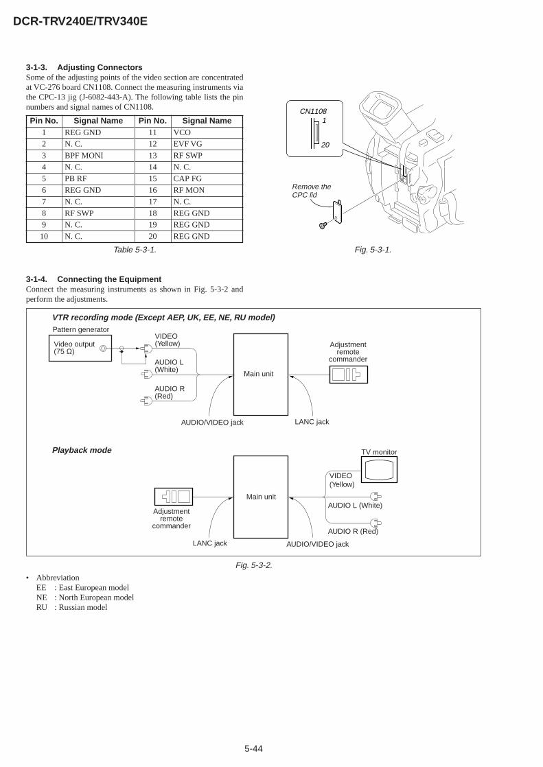
5-44
DCR-TRV240E/TRV340E
3-1-3. Adjusting ConnectorsSome of the adjusting points of the video section are concentratedat VC-276 board CN1108. Connect the measuring instruments viathe CPC-13 jig (J-6082-443-A). The following table lists the pinnumbers and signal names of CN1108.
Table 5-3-1.
3-1-4. Connecting the EquipmentConnect the measuring instruments as shown in Fig. 5-3-2 andperform the adjustments.
Fig. 5-3-2.
VTR recording mode (Except AEP, UK, EE, NE, RU model)
Playback mode
Adjustmentremote
commander
LANC jack
Main unit
AUDIO/VIDEO jack
TV monitor
VIDEO(Yellow)
AUDIO L (White)
AUDIO R (Red)
Main unit
LANC jackAUDIO/VIDEO jack
Adjustmentremote
commander
VIDEO(Yellow)
AUDIO L(White)
AUDIO R(Red)
Pattern generator
Video output(75 Ω)
Pin No.1
2
3
4
5
6
7
8
9
10
Signal NameREG GND
N. C.
BPF MONI
N. C.
PB RF
REG GND
N. C.
RF SWP
N. C.
N. C.
Pin No.11
12
13
14
15
16
17
18
19
20
Signal NameVCO
EVF VG
RF SWP
N. C.
CAP FG
RF MON
N. C.
REG GND
REG GND
REG GND
CN1108
20
1
Remove the CPC lid
Fig. 5-3-1.
• AbbreviationEE : East European modelNE : North European modelRU : Russian model
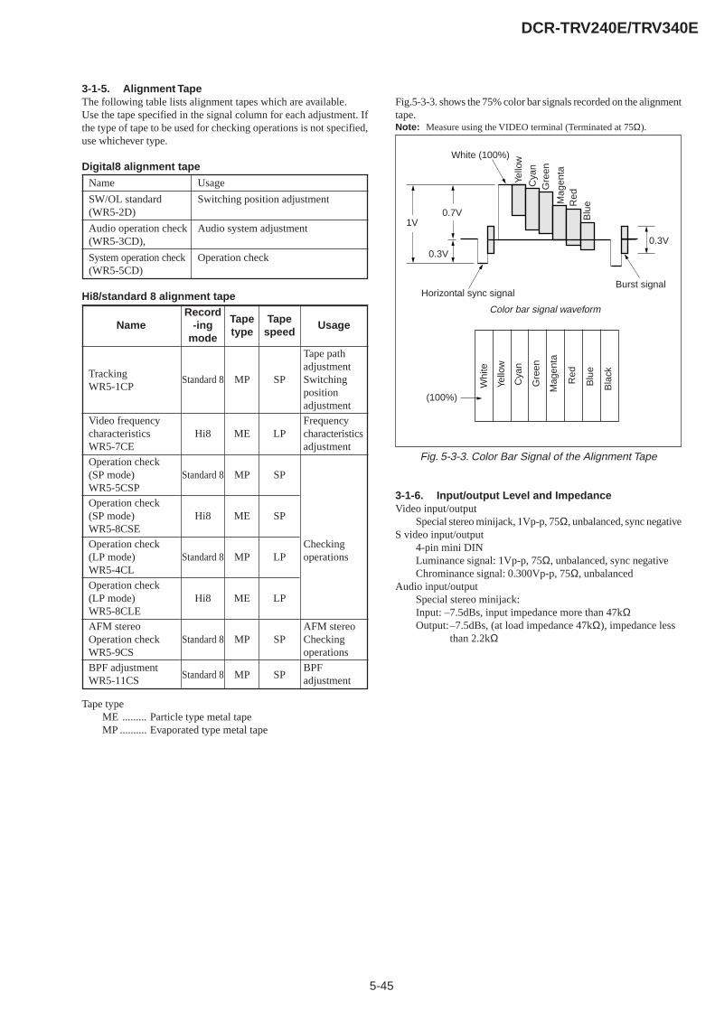
5-45
DCR-TRV240E/TRV340E
3-1-5. Alignment TapeThe following table lists alignment tapes which are available.Use the tape specified in the signal column for each adjustment. Ifthe type of tape to be used for checking operations is not specified,use whichever type.
Digital8 alignment tape
Name Usage
SW/OL standard Switching position adjustment(WR5-2D)
Audio operation check Audio system adjustment(WR5-3CD),
System operation check Operation check(WR5-5CD)
Hi8/standard 8 alignment tape
Fig. 5-3-3. Color Bar Signal of the Alignment Tape
3-1-6. Input/output Level and ImpedanceVideo input/output
Special stereo minijack, 1Vp-p, 75Ω, unbalanced, sync negativeS video input/output
4-pin mini DINLuminance signal: 1Vp-p, 75Ω, unbalanced, sync negativeChrominance signal: 0.300Vp-p, 75Ω, unbalanced
Audio input/outputSpecial stereo minijack:Input: –7.5dBs, input impedance more than 47kΩOutput:–7.5dBs, (at load impedance 47kΩ), impedance less
than 2.2kΩ
Tape typeME ......... Particle type metal tapeMP .......... Evaporated type metal tape
Color bar signal waveform
Name
TrackingWR5-1CP
Video frequencycharacteristicsWR5-7CE
Operation check(SP mode)WR5-5CSP
Operation check(SP mode)WR5-8CSE
Operation check(LP mode)WR5-4CL
Operation check(LP mode)WR5-8CLE
AFM stereoOperation checkWR5-9CS
BPF adjustmentWR5-11CS
Record-ing
mode
Standard 8
Hi8
Standard 8
Hi8
Standard 8
Hi8
Standard 8
Standard 8
Tapetype
MP
ME
MP
ME
MP
ME
MP
MP
Tapespeed
SP
LP
SP
SP
LP
LP
SP
SP
Usage
Tape pathadjustmentSwitchingpositionadjustment
Frequencycharacteristicsadjustment
Checkingoperations
AFM stereoCheckingoperations
BPFadjustment
Fig.5-3-3. shows the 75% color bar signals recorded on the alignmenttape.Note: Measure using the VIDEO terminal (Terminated at 75Ω).
1V0.7V
0.3V
White (100%)
Yello
w
Cya
nG
reen
Mag
enta
Red
Blu
e
Burst signalHorizontal sync signal
0.3V
(100%)
Yello
w
Cya
n
Gre
en
Mag
enta
Red
Blu
e
Whi
te
Bla
ck
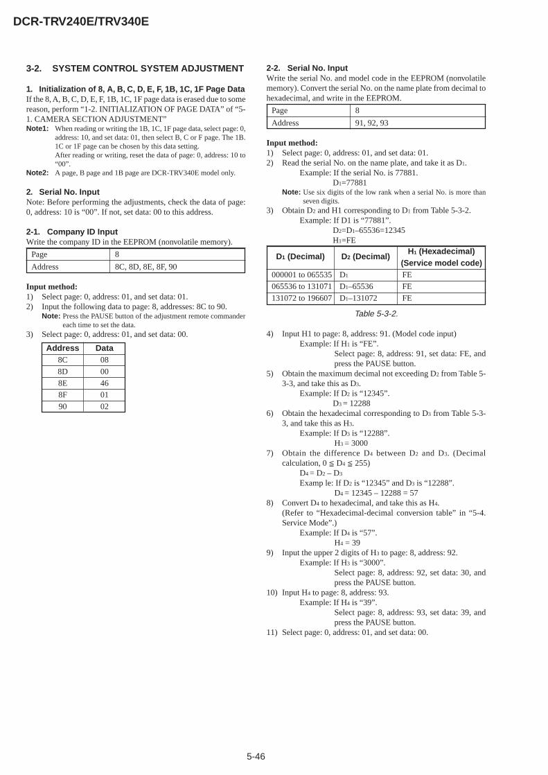
5-46
DCR-TRV240E/TRV340E
3-2. SYSTEM CONTROL SYSTEM ADJUSTMENT
1. Initialization of 8, A, B, C, D, E, F, 1B, 1C, 1F Page DataIf the 8, A, B, C, D, E, F, 1B, 1C, 1F page data is erased due to somereason, perform “1-2. INITIALIZATION OF PAGE DATA” of “5-1. CAMERA SECTION ADJUSTMENT”Note1: When reading or writing the 1B, 1C, 1F page data, select page: 0,
address: 10, and set data: 01, then select B, C or F page. The 1B.1C or 1F page can be chosen by this data setting.After reading or writing, reset the data of page: 0, address: 10 to“00”.
Note2: A page, B page and 1B page are DCR-TRV340E model only.
2. Serial No. InputNote: Before performing the adjustments, check the data of page:0, address: 10 is “00”. If not, set data: 00 to this address.
2-1. Company ID InputWrite the company ID in the EEPROM (nonvolatile memory).
Page 8
Address 8C, 8D, 8E, 8F, 90
Input method:1) Select page: 0, address: 01, and set data: 01.2) Input the following data to page: 8, addresses: 8C to 90.
Note: Press the PAUSE button of the adjustment remote commandereach time to set the data.
3) Select page: 0, address: 01, and set data: 00.
2-2. Serial No. InputWrite the serial No. and model code in the EEPROM (nonvolatilememory). Convert the serial No. on the name plate from decimal tohexadecimal, and write in the EEPROM.
Page 8
Address 91, 92, 93
Input method:1) Select page: 0, address: 01, and set data: 01.2) Read the serial No. on the name plate, and take it as D1.
Example: If the serial No. is 77881.D1=77881
Note: Use six digits of the low rank when a serial No. is more thanseven digits.
3) Obtain D2 and H1 corresponding to D1 from Table 5-3-2.Example: If D1 is “77881”.
D2=D1–65536=12345H1=FE
Table 5-3-2.
4) Input H1 to page: 8, address: 91. (Model code input)Example: If H1 is “FE”.
Select page: 8, address: 91, set data: FE, andpress the PAUSE button.
5) Obtain the maximum decimal not exceeding D2 from Table 5-3-3, and take this as D3.
Example: If D2 is “12345”.D3 = 12288
6) Obtain the hexadecimal corresponding to D3 from Table 5-3-3, and take this as H3.
Example: If D3 is “12288”.H3 = 3000
7) Obtain the difference D4 between D2 and D3. (Decimalcalculation, 0 D4 255)
D4 = D2 – D3
Examp le: If D2 is “12345” and D3 is “12288”.D4 = 12345 – 12288 = 57
8) Convert D4 to hexadecimal, and take this as H4.(Refer to “Hexadecimal-decimal conversion table” in “5-4.Service Mode”.)
Example: If D4 is “57”.H4 = 39
9) Input the upper 2 digits of H3 to page: 8, address: 92.Example: If H3 is “3000”.
Select page: 8, address: 92, set data: 30, andpress the PAUSE button.
10) Input H4 to page: 8, address: 93.Example: If H4 is “39”.
Select page: 8, address: 93, set data: 39, andpress the PAUSE button.
11) Select page: 0, address: 01, and set data: 00.
Address8C
8D
8E
8F
90
Data08
00
46
01
02
D1 (Decimal)
000001 to 065535
065536 to 131071
131072 to 196607
D2 (Decimal)
D1
D1–65536
D1–131072
H1 (Hexadecimal)(Service model code)FE
FE
FE
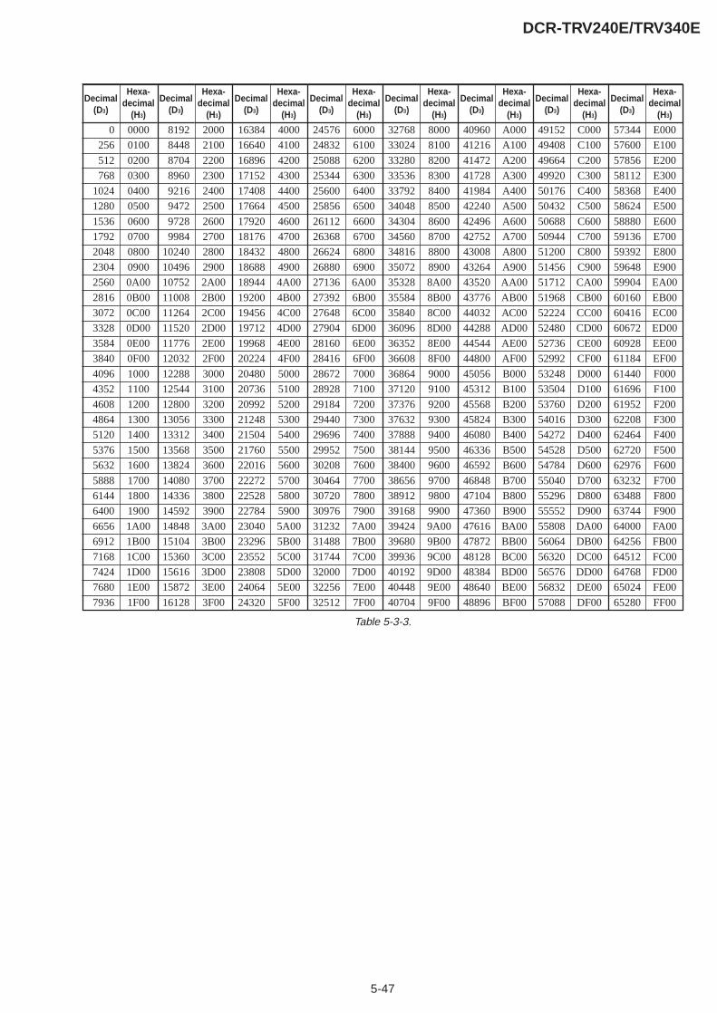
5-47
DCR-TRV240E/TRV340E
Decimal(D3)
Hexa-decimal
(H3)
Decimal(D3)
Hexa-decimal
(H3)
Decimal(D3)
Hexa-decimal
(H3)
Decimal(D3)
Hexa-decimal
(H3)
Decimal(D3)
Hexa-decimal
(H3)
Decimal(D3)
Hexa-decimal
(H3)
Decimal(D3)
Hexa-decimal
(H3)
Decimal(D3)
Hexa-decimal
(H3)
0
256
512
768
1024
1280
1536
1792
2048
2304
2560
2816
3072
3328
3584
3840
4096
4352
4608
4864
5120
5376
5632
5888
6144
6400
6656
6912
7168
7424
7680
7936
8192
8448
8704
8960
9216
9472
9728
9984
10240
10496
10752
11008
11264
11520
11776
12032
12288
12544
12800
13056
13312
13568
13824
14080
14336
14592
14848
15104
15360
15616
15872
16128
16384
16640
16896
17152
17408
17664
17920
18176
18432
18688
18944
19200
19456
19712
19968
20224
20480
20736
20992
21248
21504
21760
22016
22272
22528
22784
23040
23296
23552
23808
24064
24320
24576
24832
25088
25344
25600
25856
26112
26368
26624
26880
27136
27392
27648
27904
28160
28416
28672
28928
29184
29440
29696
29952
30208
30464
30720
30976
31232
31488
31744
32000
32256
32512
32768
33024
33280
33536
33792
34048
34304
34560
34816
35072
35328
35584
35840
36096
36352
36608
36864
37120
37376
37632
37888
38144
38400
38656
38912
39168
39424
39680
39936
40192
40448
40704
40960
41216
41472
41728
41984
42240
42496
42752
43008
43264
43520
43776
44032
44288
44544
44800
45056
45312
45568
45824
46080
46336
46592
46848
47104
47360
47616
47872
48128
48384
48640
48896
49152
49408
49664
49920
50176
50432
50688
50944
51200
51456
51712
51968
52224
52480
52736
52992
53248
53504
53760
54016
54272
54528
54784
55040
55296
55552
55808
56064
56320
56576
56832
57088
57344
57600
57856
58112
58368
58624
58880
59136
59392
59648
59904
60160
60416
60672
60928
61184
61440
61696
61952
62208
62464
62720
62976
63232
63488
63744
64000
64256
64512
64768
65024
65280
0000
0100
0200
0300
0400
0500
0600
0700
0800
0900
0A00
0B00
0C00
0D00
0E00
0F00
1000
1100
1200
1300
1400
1500
1600
1700
1800
1900
1A00
1B00
1C00
1D00
1E00
1F00
2000
2100
2200
2300
2400
2500
2600
2700
2800
2900
2A00
2B00
2C00
2D00
2E00
2F00
3000
3100
3200
3300
3400
3500
3600
3700
3800
3900
3A00
3B00
3C00
3D00
3E00
3F00
4000
4100
4200
4300
4400
4500
4600
4700
4800
4900
4A00
4B00
4C00
4D00
4E00
4F00
5000
5100
5200
5300
5400
5500
5600
5700
5800
5900
5A00
5B00
5C00
5D00
5E00
5F00
6000
6100
6200
6300
6400
6500
6600
6700
6800
6900
6A00
6B00
6C00
6D00
6E00
6F00
7000
7100
7200
7300
7400
7500
7600
7700
7800
7900
7A00
7B00
7C00
7D00
7E00
7F00
8000
8100
8200
8300
8400
8500
8600
8700
8800
8900
8A00
8B00
8C00
8D00
8E00
8F00
9000
9100
9200
9300
9400
9500
9600
9700
9800
9900
9A00
9B00
9C00
9D00
9E00
9F00
A000
A100
A200
A300
A400
A500
A600
A700
A800
A900
AA00
AB00
AC00
AD00
AE00
AF00
B000
B100
B200
B300
B400
B500
B600
B700
B800
B900
BA00
BB00
BC00
BD00
BE00
BF00
C000
C100
C200
C300
C400
C500
C600
C700
C800
C900
CA00
CB00
CC00
CD00
CE00
CF00
D000
D100
D200
D300
D400
D500
D600
D700
D800
D900
DA00
DB00
DC00
DD00
DE00
DF00
E000
E100
E200
E300
E400
E500
E600
E700
E800
E900
EA00
EB00
EC00
ED00
EE00
EF00
F000
F100
F200
F300
F400
F500
F600
F700
F800
F900
FA00
FB00
FC00
FD00
FE00
FF00
Table 5-3-3.

5-48
DCR-TRV240E/TRV340E
3-3. SERVO AND RF SYSTEM ADJUSTMENTBefore perform the servo and RF system adjustments, check thatthe specified value of “36 MHz Origin Oscillation Adjustment” of“VIDEO SYSTEM ADJUSTMENT” is satisfied.And check that the data of page: 0, address: 10 is “00”. If not, setdata: 00 to this address.
Adjusting Procedure:1. REEL FG adjustment2. PLL f0 & LPF f0 adjustment3. Switching position adjustment4. AGC center level and APC & AEQ adjustment5. PLL f0 & LPF f0 fine adjustment6. Hi8/Standrd8 switching position adjustment7. Cap FG duty adjustment
1. REEL FG Adjustment (VC-276 board)Compensates the dispersion of the hall elements.
Measurement Point Display data of page: 3, address: 03
Measuring Instrument Adjustment remote commander
Adjustment Page C
Adjustment Address 17, 2F
Specified Value 00 or 01 or 04 or 05
Note: The data of page: 0, address: 10 must be “00”.
Adjusting method:
Order Page Address Data Procedure
1 Close the cassette compartmentwithout inserting a cassette.
2 0 01 01 Set the data.
3 3 01 1C Set the data, and press PAUSEbutton.
4 3 02 Check that the data changes to“00”,
5 3 03 Check that the data is “00” or “01”or “04” or “05”. (Note)
6 0 01 00 Set the data.
Note: If the data is other value, adjustment has errors. (Take an appropriateremedial measures according to the errors referring to the followingtable.)
Data Contents of defect
02, 03, 06, 07 T reel is defective
08, 09, 0C, 0D S reel is defective
0A, 0B, 0E, 0F S reel and T reel are defective
2. PLL f0 & LPF f0 Adjustment (VC-276 board)
Mode VTR stop
Measurement Point Display data of page: 3, address: 02, 03
Measuring Instrument Adjustment remote commander
Adjustment Page C
Adjustment Address 1F, 20, 22, 29
Specified Value Data of page: 3, address: 02 is “00”.Data of page: 3, address: 03 is “00”.
Note1: The data of page: 0, address: 10 must be “00”.
Adjusting method:
Order Page Address Data Procedure
1 0 01 01 Set the data.
2 C 21 CA Set the data, and press PAUSEbutton.
3 3 01 00 Set the data, and press PAUSEbutton.
4 3 01 30 Set the data, and press PAUSEbutton.
5 3 02 Check that the data changes to“00” with in 10 sec. (Note2)
6 3 03 Check that the data is “00”.(Note2)
7 0 01 00 Set the data.
Note2: If it isn’t satisfied, select page: C, address: 21, set the followingdata, and press the PAUSE button, and repeat steps 3 to 6.
Setting data
When the data of page: C, address: 21 is “CA”. CE
When the data of page: C, address: 21 is “CE”. C6
When the data of page: C, address: 21 is “C6”. D2
When the data of page: C, address: 21 is “D2” C2
There are errors when it isn’t satisfied even if the above treatment isdone.If bit2, bit3, bit4, bit5 or bit 6 of the data of page: 3, address: 03 is“1”, there are errors. For the error contents, see the following table.(For the bit values, refer to “5-4. SERVICE MODE”, “4-3. 3. Bitvalue discrimination”.)
Bit value of page: 3, Error contentsaddress: 03 data
bit 2 = 1 or bit 3 = 1 PLL f0 fine adjustment is defective
bit 4 = 1 or bit 5 = 1 PLL f0 adjustment is defective
bit 6 = 1 LPF f0 adjustment is defective

5-49
DCR-TRV240E/TRV340E
3. Switching Position Adjustment (VC-276 board)To obtain normal playback waveform output during the Digital8playback mode, adjust the switching position.
Mode VTR playback
Signal SW/OL reference tape (WR5-2D)
Measurement Point Display data of page: 3, address: 03
Measuring Instrument Adjustment remote commander
Adjustment Page C
Adjustment Address 10, 11, 12, 13
Specified Value 00
Note1: The data of page: 0, address: 10 must be “00”.
Adjusting method:
Order Page Address Data Procedure
1 Insert the SW/OL reference tapeand enter the VTR STOP mode.
2 0 01 01 Set the data.
3 C 10 EE Set the data, and press PAUSEbutton.
4 3 21 Check that the data is “02”.(Note2)
5 3 01 0D Set the data, and press PAUSEbutton.
6 3 02 Check that the data changes to“00” in the following order.“0E”→“29”→“0E”→“20”→“00”
7 3 03 Check that the data is “00”.(Note3)
8 C 10 Check that the data is other than“EE”. (Note3)
9 0 01 00 Set the data.
Note2: If the data of page: 3, address: 21 is “72”, the tape top being played.After playing the tape for 1 to 2 seconds, stop it, perform step 5and higher.
Note3: If the data is other than “00”, select page: C, address: 21, afterwrite down the data, set data: 10, and press the PAUSE button,and repeat from step1.There are errors when the data of page: 3, address: 03 is other than“00” even if this treatment is done. Select page: C, address: 21, setthe data written down, and press the PAUSE button.If bit 0 of the data is “1”, the A channel is defective. If bit 1 is “1”,the B channel is defective. Contents of the defect is written intopage: C, addresses: 10 and 12. See the following table. (For the bitvalues, refer to “5-4. SERVICE MODE”, “4-3. 3. Bit valuediscrimination”. ) If bit 3 of the data is “1”,the tape end beingplayed, and adjustment has errors.
Note4: If the data is “EE”, rewind the tape and repeat steps 1 to 7.
When the A channel is defective
Data of page: C, Contents of defectaddress: 10
EE Writing into EEPROM (IC4502) isdefective
E8 Adjustment data is out of range
E7 No data is returned from IC3301
When the B channel is defective
Data of page: C, Contents of defectaddress: 12
E8 Adjustment data is out of range
E7 No data is returned from IC3301
4. AGC Center Level and APC & AEQ AdjustmentNote: The data of page: 0, address: 10 must be “00”.
Use a Hi8 MP tape.
4-1. Preparations before adjustments
Mode Camera recording
Subject Arbitrary
Adjusting method:
Order Page Address Data Procedure
1 0 01 01 Set the data.
2 8 21 C8 Set the data.
3 Record the camera signal for threeminutes.
4-2. AGC Center Level Adjustment (VC-276 board)
Mode Playback
Signal Recorded signal at “Preparations beforeadjustments”
Measurement Point Pin qh of CN1108 (RF MON) (Note 1)Ext. trigger: Pin qd of CN1108 (RFSWP)
Measuring Instrument Oscilloscope
Adjustment Page C
Adjustment Address 1E
Specified Value The data of page: 3, address: 03 is “00”
Note 1: Connect a 75Ω resistor between Pin qh and Pin w; (GND) ofCN1108.75Ω resistor (Parts code: 1-247-804-11)
Adjusting method:
Order Page Address Data Procedure
1 Playback the recorded signal at“Preparations before adjustments”
2 0 01 01 Set the data.
3 <2> <4D> <40> Set the data. (Note2)[7] [62] [01]
4 3 33 08 Set the data.
5 Confirm that the playback RFsignal is stable. (Fig. 5-3-4.)
6 3 01 23 Set the data, and press PAUSEbutton.
7 3 02 Check that the data is “00”.
8 3 03 Check that the data is “00”.(Note3)
9 Perform “APC & AEQ Adjustment”.
Note 2: < >: DCR-TRV240E, [ ]: DCR-TRV340ENote 3: If the data of page: 3, address: 03 is other than “00”, adjustment
has errors.
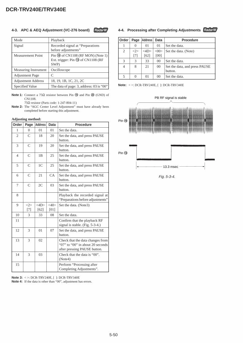
5-50
DCR-TRV240E/TRV340E
4-3. APC & AEQ Adjustment (VC-276 board)
Mode Playback
Signal Recorded signal at “Preparationsbefore adjustments”
Measurement Point Pin qh of CN1108 (RF MON) (Note 1)Ext. trigger: Pin qd of CN1108 (RFSWP)
Measuring Instrument Oscilloscope
Adjustment Page C
Adjustment Address 18, 19, 1B, 1C, 21, 2C
Specified Value The data of page: 3, address: 03 is “00”
Note 1: Connect a 75Ω resistor between Pin qh and Pin w; (GND) ofCN1108.75Ω resistor (Parts code: 1-247-804-11)
Note 2: The “AGC Center Level Adjustment” must have already beencompleted before starting this adjustment.
Adjusting method:
Order Page Address Data Procedure
1 0 01 01 Set the data.
2 C 18 20 Set the data, and press PAUSEbutton.
3 C 19 20 Set the data, and press PAUSEbutton.
4 C 1B 25 Set the data, and press PAUSEbutton.
5 C 1C 25 Set the data, and press PAUSEbutton.
6 C 21 CA Set the data, and press PAUSEbutton.
7 C 2C 03 Set the data, and press PAUSEbutton.
8 Playback the recorded signal at“Preparations before adjustments”
9 <2> <4D> <40> Set the data. (Note3)[7] [62] [01]
10 3 33 08 Set the data.
11 Confirm that the playback RFsignal is stable. (Fig. 5-3-4.)
12 3 01 07 Set the data, and press PAUSEbutton.
13 3 02 Check that the data changes from“07” to “00” in about 20 secondsafter pressing PAUSE button.
14 3 03 Check that the data is “00”.(Note4)
15 Perform “Processing afterCompleting Adjustments”.
Note 3: < >: DCR-TRV240E, [ ]: DCR-TRV340ENote 4: If the data is other than “00”, adjustment has errors.
4-4. Processing after Completing Adjustments
Order Page Address Data Procedure
1 0 01 01 Set the data.
2 <2> <4D> <00> Set the data. (Note)[7] [62] [00]
3 3 33 00 Set the data.
4 8 21 00 Set the data, and press PAUSEbutton.
5 0 01 00 Set the data.
Note: < >: DCR-TRV240E, [ ]: DCR-TRV340E
Fig. 5-3-4.
13.3 msec
PB RF signal is stable
Pin qd
Pin qh

5-51
DCR-TRV240E/TRV340E
5. PLL f0 & LPF f0 Fine Adjustment (VC-276 board)
Mode VTR stop
Signal Arbitrary
Measurement Point Display data of page: 3, address: 02, 03
Measuring Instrument Adjustment remote commander
Adjustment Page C
Adjustment Address 1F, 20, 22, 29
Specified Value Display data of page: 3, address: 02 is“00”.Display data of page: 3, address: 03 is“00”.
Note1: The data of page: 0, address: 10 must be “00”.
Adjusting method:
Order Page Address Data Procedure
1 0 01 01 Set the data.
2 3 01 30 Set the data, and press PAUSEbutton.
3 3 02 Check that the data changes to“00” with in 10 sec. (Note2)
4 3 03 Check that the data is “00”.(Note3)
5 0 01 00 Set the data.
Note2: If it isn’t satisfied, there are errors.Note3: If the data of page: 3, address: 03 is other than “00”, there are
errors. For the error contents, see the following table. (For the bitvalues, refer to “5-4. SERVICE MODE”, “4-3. 3. Bit valuediscrimination”.)
6. Hi8/Standard8 Switching Position Adjustment(VC-276 board)
If deviated in this case causes switching noise or jitter on the Hi8/Standard8 mode played back screen.
Mode Playback
Signal Hi8/Standard8 alignment tape: For tracking adjustment (WR5-1CP)
Measurement Point CH1: Pin 8 of CN1108 (RF SWP)CH2: Pin 5 of CN1108 (PB RF)
Measuring Instrument Oscilloscope
Adjustment Page C
Adjustment Address 40, 41
Specified Value t1 = 0 ± 10 µsec
Note1: The data of page: 0, address: 10 must be “00”.
Adjusting Method:
Order Page Address Data Procedure
1 Set to the stop mode.
2 0 01 01 Set the data.
3 C 3E 40 Set the data, and press PAUSEbutton.
4 <2> <4D> <80> Set the data. (Note2)[7] [62] [02]
5 Set to the playback mode.
6 C 40 Change the data and minimize“t1”. (Coarse adjustment)
7 C 40 Press PAUSE button
8 C 41 Change the data and adjust so thatthe switching position (t1)becomes the specified value. (Fineadjustment)
9 C 41 Press PAUSE button
10 C 3E 00 Set the data, and press PAUSEbutton.
11 <2> <4D> <00> Set the data. (Note2)[7] [62] [00]
12 0 01 00 Set the data.
Note2: < >: DCR-TRV240E, [ ]: DCR-TRV340E
Fig. 5-3-5.
CH1
CH2
Enlargement
t1=0 ± 10 µsec
CH1
CH2
Bit value of page: 3, Error contentsaddress: 03
bit 2 = 1 or bit 3 = 1 PLL f0 fine adjustment is defective
bit 4 = 1 or bit 5 = 1 PLL f0 adjustment is defective
bit 6 = 1 LPF f0 adjustment is defective

5-52
DCR-TRV240E/TRV340E
7. CAP FG Duty Adjustment (VC-276 board)Set the Cap FG signal duty cycle to 50% to establish an appropriatecapstan servo. If deviated, the uneven rotation of capstan and noisecan occur in the Hi8/Standard8 LP mode.
Mode Playback
Signal Hi8/standard 8 alignment tape :For checking operation
(WR5-5CSP)
Measurement Point Pin qg of CN1108 (CAP FG)
Measuring Instrument Oscilloscope
Adjustment Page C
Adjustment Address 16
Specified value Duty = 50 ± 1 %
Note1: The data of page: 0, address: 10 must be “00”.
Adjusting method:
Order Page Address Data Procedure
1 Set to the playback mode.
2 0 01 01 Set the data.
3 3 01 00 Set the data, and press PAUSEbutton.
4 3 01 81 Set the data, and press PAUSEbutton.
5 3 02 Check that the data changes from“81” to “00”.
6 3 03 Check that the data is “00”.(Note2)
7 Check that Duty of CAP FG signalsatisfies the specified value. If not,repeat steps 3 to 7.
8 0 01 00 Set the data.
Note2: If the data of page: 3, address: 03 is other than “00”, there areerrors. For the error contents, see the following table. (For the bitvalues, refer to “5-4. SERVICE MODE”, “4-3. 3. Bit valuediscrimination”.)
Bit value of page: 3, Error contentsaddress: 03
bit 0 = 1 Adjustment time-out
bit 1 = 1 Hi8/Standard8 mode wasn’t set up.
Fig. 5-3-6.
A
B Duty = A/B × 100 [%]
Center of movement
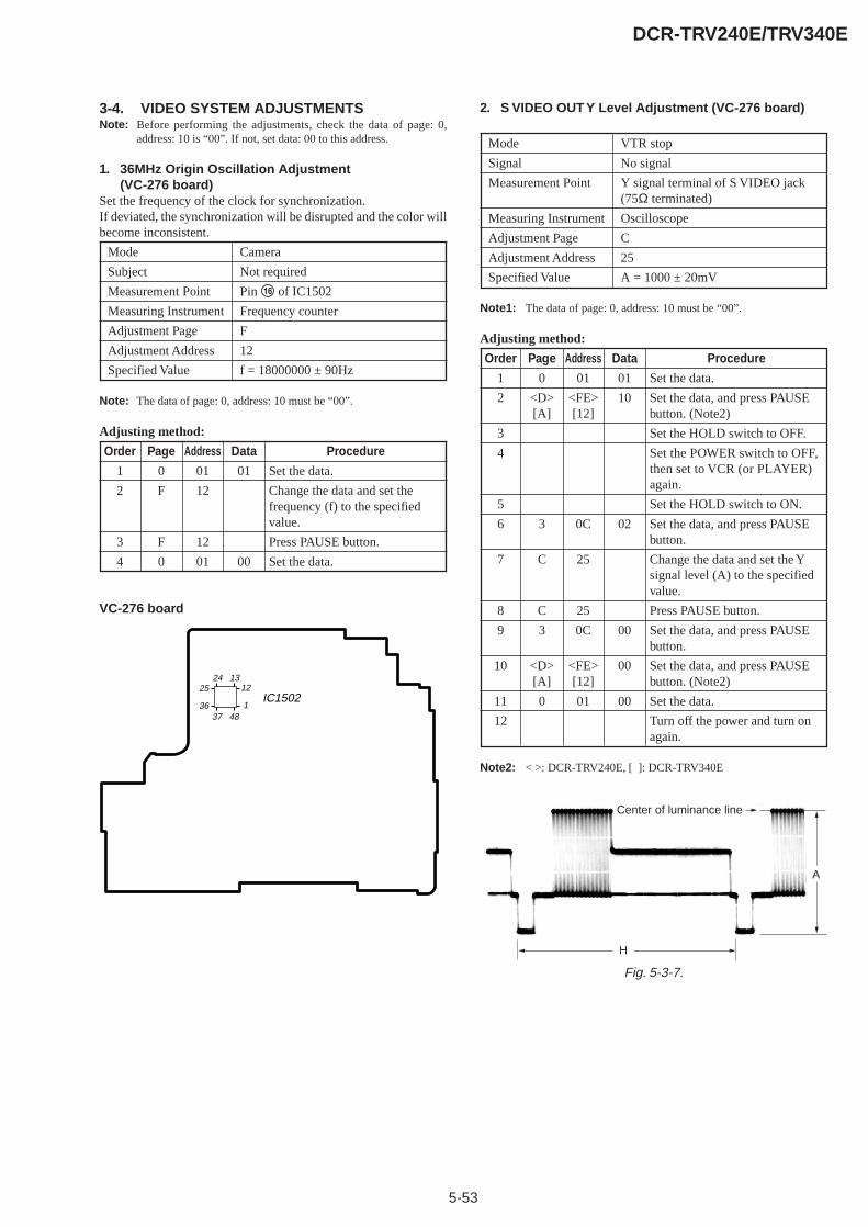
5-53
DCR-TRV240E/TRV340E
3-4. VIDEO SYSTEM ADJUSTMENTSNote: Before performing the adjustments, check the data of page: 0,
address: 10 is “00”. If not, set data: 00 to this address.
1. 36MHz Origin Oscillation Adjustment(VC-276 board)
Set the frequency of the clock for synchronization.If deviated, the synchronization will be disrupted and the color willbecome inconsistent.
Mode Camera
Subject Not required
Measurement Point Pin qh of IC1502
Measuring Instrument Frequency counter
Adjustment Page F
Adjustment Address 12
Specified Value f = 18000000 ± 90Hz
Note: The data of page: 0, address: 10 must be “00”.
Adjusting method:
Order Page Address Data Procedure
1 0 01 01 Set the data.
2 F 12 Change the data and set thefrequency (f) to the specifiedvalue.
3 F 12 Press PAUSE button.
4 0 01 00 Set the data.
2. S VIDEO OUT Y Level Adjustment (VC-276 board)
Mode VTR stop
Signal No signal
Measurement Point Y signal terminal of S VIDEO jack(75Ω terminated)
Measuring Instrument Oscilloscope
Adjustment Page C
Adjustment Address 25
Specified Value A = 1000 ± 20mV
Note1: The data of page: 0, address: 10 must be “00”.
Adjusting method:
Order Page Address Data Procedure
1 0 01 01 Set the data.
2 <D> <FE> 10 Set the data, and press PAUSE[A] [12] button. (Note2)
3 Set the HOLD switch to OFF.
4 Set the POWER switch to OFF,then set to VCR (or PLAYER)again.
5 Set the HOLD switch to ON.
6 3 0C 02 Set the data, and press PAUSEbutton.
7 C 25 Change the data and set the Ysignal level (A) to the specifiedvalue.
8 C 25 Press PAUSE button.
9 3 0C 00 Set the data, and press PAUSEbutton.
10 <D> <FE> 00 Set the data, and press PAUSE[A] [12] button. (Note2)
11 0 01 00 Set the data.
12 Turn off the power and turn onagain.
Note2: < >: DCR-TRV240E, [ ]: DCR-TRV340E
VC-276 board
IC150225
36
1224 13
37 481
Fig. 5-3-7.
H
Center of luminance line
A
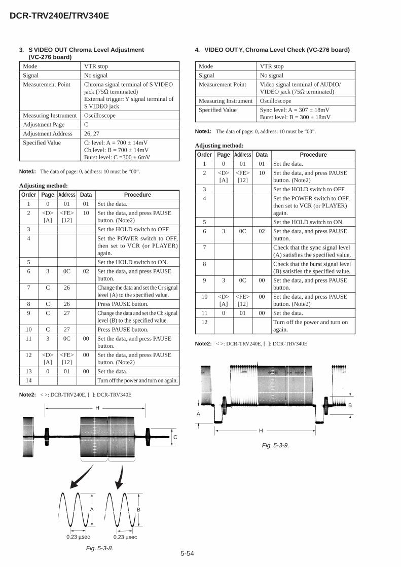
5-54
DCR-TRV240E/TRV340E
3. S VIDEO OUT Chroma Level Adjustment(VC-276 board)
Mode VTR stop
Signal No signal
Measurement Point Chroma signal terminal of S VIDEOjack (75Ω terminated)External trigger: Y signal terminal ofS VIDEO jack
Measuring Instrument Oscilloscope
Adjustment Page C
Adjustment Address 26, 27
Specified Value Cr level: A = 700 ± 14mVCb level: B = 700 ± 14mVBurst level: C =300 ± 6mV
Note1: The data of page: 0, address: 10 must be “00”.
Adjusting method:
Order Page Address Data Procedure
1 0 01 01 Set the data.
2 <D> <FE> 10 Set the data, and press PAUSE[A] [12] button. (Note2)
3 Set the HOLD switch to OFF.
4 Set the POWER switch to OFF,then set to VCR (or PLAYER)again.
5 Set the HOLD switch to ON.
6 3 0C 02 Set the data, and press PAUSEbutton.
7 C 26 Change the data and set the Cr signallevel (A) to the specified value.
8 C 26 Press PAUSE button.
9 C 27 Change the data and set the Cb signallevel (B) to the specified value.
10 C 27 Press PAUSE button.
11 3 0C 00 Set the data, and press PAUSEbutton.
12 <D> <FE> 00 Set the data, and press PAUSE[A] [12] button. (Note2)
13 0 01 00 Set the data.
14 Turn off the power and turn on again.
Note2: < >: DCR-TRV240E, [ ]: DCR-TRV340E
4. VIDEO OUT Y, Chroma Level Check (VC-276 board)
Mode VTR stop
Signal No signal
Measurement Point Video signal terminal of AUDIO/VIDEO jack (75Ω terminated)
Measuring Instrument Oscilloscope
Specified Value Sync level: A = 307 ± 18mVBurst level: B = 300 ± 18mV
Note1: The data of page: 0, address: 10 must be “00”.
Adjusting method:
Order Page Address Data Procedure
1 0 01 01 Set the data.
2 <D> <FE> 10 Set the data, and press PAUSE[A] [12] button. (Note2)
3 Set the HOLD switch to OFF.
4 Set the POWER switch to OFF,then set to VCR (or PLAYER)again.
5 Set the HOLD switch to ON.
6 3 0C 02 Set the data, and press PAUSEbutton.
7 Check that the sync signal level(A) satisfies the specified value.
8 Check that the burst signal level(B) satisfies the specified value.
9 3 0C 00 Set the data, and press PAUSEbutton.
10 <D> <FE> 00 Set the data, and press PAUSE[A] [12] button. (Note2)
11 0 01 00 Set the data.
12 Turn off the power and turn onagain.
Note2: < >: DCR-TRV240E, [ ]: DCR-TRV340E
Fig. 5-3-8.
H
C
A
0.23 µsec
B
0.23 µsec
Fig. 5-3-9.
H
B
A
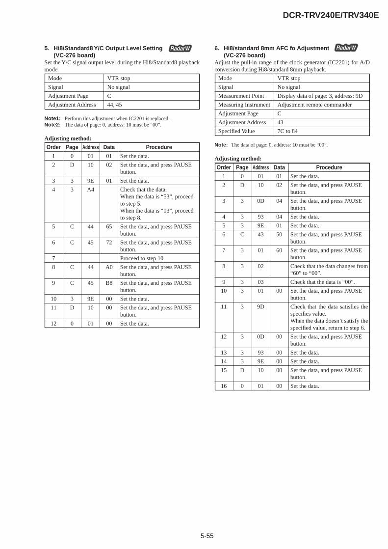
5-55
DCR-TRV240E/TRV340E
5. Hi8/Standard8 Y/C Output Level Setting(VC-276 board)
Set the Y/C signal output level during the Hi8/Standard8 playbackmode.
Mode VTR stop
Signal No signal
Adjustment Page C
Adjustment Address 44, 45
Note1: Perform this adjustment when IC2201 is replaced.Note2: The data of page: 0, address: 10 must be “00”.
Adjusting method:
Order Page Address Data Procedure
1 0 01 01 Set the data.
2 D 10 02 Set the data, and press PAUSEbutton.
3 3 9E 01 Set the data.
4 3 A4 Check that the data.When the data is “53”, proceedto step 5.When the data is “03”, proceedto step 8.
5 C 44 65 Set the data, and press PAUSEbutton.
6 C 45 72 Set the data, and press PAUSEbutton.
7 Proceed to step 10.
8 C 44 A0 Set the data, and press PAUSEbutton.
9 C 45 B8 Set the data, and press PAUSEbutton.
10 3 9E 00 Set the data.
11 D 10 00 Set the data, and press PAUSEbutton.
12 0 01 00 Set the data.
6. Hi8/standard 8mm AFC fo Adjustment(VC-276 board)
Adjust the pull-in range of the clock generator (IC2201) for A/Dconversion during Hi8/standard 8mm playback.
Mode VTR stop
Signal No signal
Measurement Point Display data of page: 3, address: 9D
Measuring Instrument Adjustment remote commander
Adjustment Page C
Adjustment Address 43
Specified Value 7C to 84
Note: The data of page: 0, address: 10 must be “00”.
Adjusting method:
Order Page Address Data Procedure
1 0 01 01 Set the data.
2 D 10 02 Set the data, and press PAUSEbutton.
3 3 0D 04 Set the data, and press PAUSEbutton.
4 3 93 04 Set the data.
5 3 9E 01 Set the data.
6 C 43 50 Set the data, and press PAUSEbutton.
7 3 01 60 Set the data, and press PAUSEbutton.
8 3 02 Check that the data changes from“60” to “00”.
9 3 03 Check that the data is “00”.
10 3 01 00 Set the data, and press PAUSEbutton.
11 3 9D Check that the data satisfies thespecifies value.When the data doesn’t satisfy thespecified value, return to step 6.
12 3 0D 00 Set the data, and press PAUSEbutton.
13 3 93 00 Set the data.
14 3 9E 00 Set the data.
15 D 10 00 Set the data, and press PAUSEbutton.
16 0 01 00 Set the data.
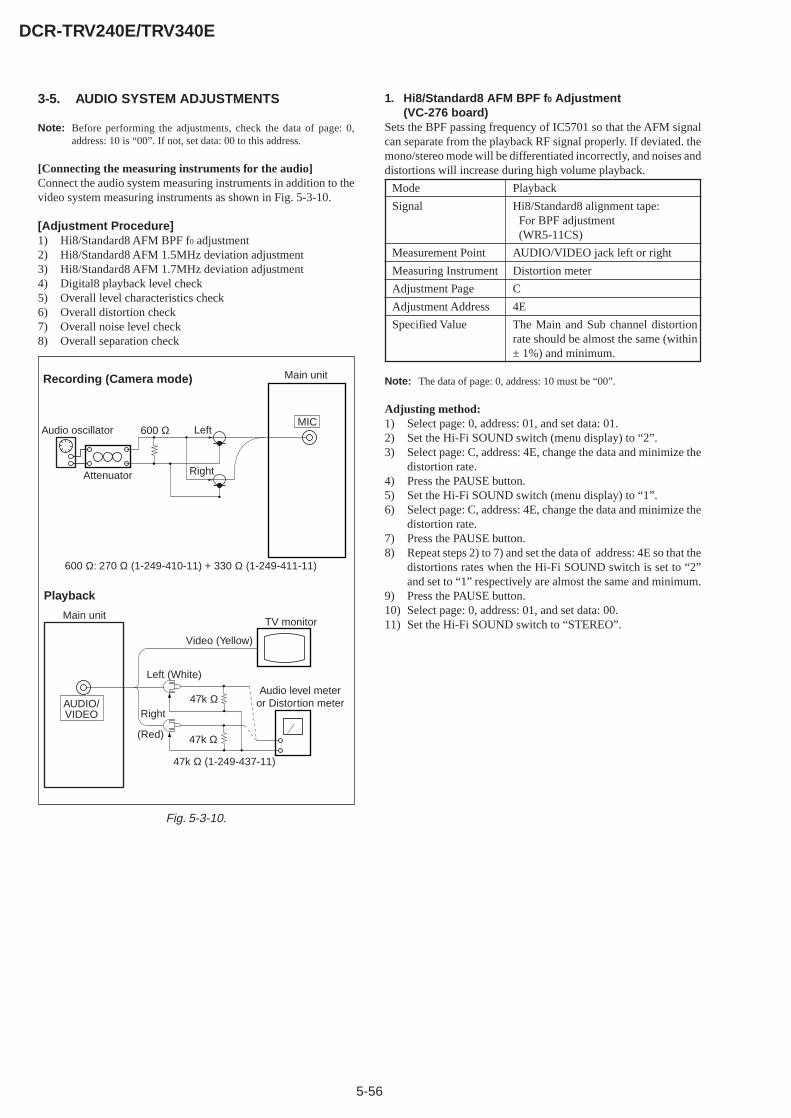
5-56
DCR-TRV240E/TRV340E
3-5. AUDIO SYSTEM ADJUSTMENTS
Note: Before performing the adjustments, check the data of page: 0,address: 10 is “00”. If not, set data: 00 to this address.
[Connecting the measuring instruments for the audio]Connect the audio system measuring instruments in addition to thevideo system measuring instruments as shown in Fig. 5-3-10.
[Adjustment Procedure]1) Hi8/Standard8 AFM BPF f0 adjustment2) Hi8/Standard8 AFM 1.5MHz deviation adjustment3) Hi8/Standard8 AFM 1.7MHz deviation adjustment4) Digital8 playback level check5) Overall level characteristics check6) Overall distortion check7) Overall noise level check8) Overall separation check
1. Hi8/Standard8 AFM BPF f0 Adjustment(VC-276 board)
Sets the BPF passing frequency of IC5701 so that the AFM signalcan separate from the playback RF signal properly. If deviated. themono/stereo mode will be differentiated incorrectly, and noises anddistortions will increase during high volume playback.
Mode Playback
Signal Hi8/Standard8 alignment tape: For BPF adjustment (WR5-11CS)
Measurement Point AUDIO/VIDEO jack left or right
Measuring Instrument Distortion meter
Adjustment Page C
Adjustment Address 4E
Specified Value The Main and Sub channel distortionrate should be almost the same (within± 1%) and minimum.
Note: The data of page: 0, address: 10 must be “00”.
Adjusting method:1) Select page: 0, address: 01, and set data: 01.2) Set the Hi-Fi SOUND switch (menu display) to “2”.3) Select page: C, address: 4E, change the data and minimize the
distortion rate.4) Press the PAUSE button.5) Set the Hi-Fi SOUND switch (menu display) to “1”.6) Select page: C, address: 4E, change the data and minimize the
distortion rate.7) Press the PAUSE button.8) Repeat steps 2) to 7) and set the data of address: 4E so that the
distortions rates when the Hi-Fi SOUND switch is set to “2”and set to “1” respectively are almost the same and minimum.
9) Press the PAUSE button.10) Select page: 0, address: 01, and set data: 00.11) Set the Hi-Fi SOUND switch to “STEREO”.
Fig. 5-3-10.
Recording (Camera mode)
Audio oscillator
Attenuator
600 Ω Left
Right
Main unit
MIC
600 Ω: 270 Ω (1-249-410-11) + 330 Ω (1-249-411-11)
Main unit
AUDIO/VIDEO
Left (White)
Right 47k Ω
47k Ω
Video (Yellow)
TV monitor
Audio level meteror Distortion meter
47k Ω (1-249-437-11)
Playback
(Red)
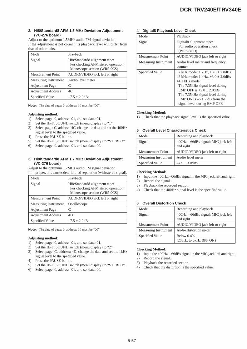
5-57
DCR-TRV240E/TRV340E
2. Hi8/Standard8 AFM 1.5 MHz Deviation Adjustment(VC-276 board)
Adjust to the optimum 1.5MHz audio FM signal deviation.If the adjustment is not correct, its playback level will differ fromthat of other units.
Mode Playback
Signal Hi8/Standard8 alignment tape: For checking AFM stereo operation Monoscope section (WR5-9CS)
Measurement Point AUDIO/VIDEO jack left or right
Measuring Instrument Audio level meter
Adjustment Page C
Adjustment Address 4C
Specified Value –7.5 ± 2.0dBs
Note: The data of page: 0, address: 10 must be “00”.
Adjusting method:1) Select page: 0, address: 01, and set data: 01.2) Set the Hi-Fi SOUND switch (menu display) to “1”.3) Select page: C, address: 4C, change the data and set the 400Hz
signal level to the specified value.4) Press the PAUSE button.5) Set the Hi-Fi SOUND switch (menu display) to “STEREO”.6) Select page: 0, address: 01, and set data: 00.
3. Hi8/Standard8 AFM 1.7 MHz Deviation Adjustment(VC-276 board)
Adjust to the optimum 1.7MHz audio FM signal deviation.If improper, this causes deteriorated separation (with stereo signal).
Mode Playback
Signal Hi8/Standard8 alignment tape: For checking AFM stereo operation Monoscope section (WR5-9CS)
Measurement Point AUDIO/VIDEO jack left or right
Measuring Instrument Oscilloscope
Adjustment Page C
Adjustment Address 4D
Specified Value –7.5 ± 2.0dBs
Note: The data of page: 0, address: 10 must be “00”.
Adjusting method:1) Select page: 0, address: 01, and set data: 01.2) Set the Hi-Fi SOUND switch (menu display) to “2”.3) Select page: C, address: 4D, change the data and set the 1kHz
signal level to the specified value.4) Press the PAUSE button.5) Set the Hi-Fi SOUND switch (menu display) to “STEREO”.6) Select page: 0, address: 01, and set data: 00.
4. Digital8 Playback Level Check
Mode Playback
Signal Digital8 alignment tape: For audio operation check (WR5-3CD)
Measurement Point AUDIO/VIDEO jack left or right
Measuring Instrument Audio level meter and frequencycounter
Specified Value 32 kHz mode: 1 kHz, +3.0 ± 2.0dBs48 kHz mode: 1 kHz, +3.0 ± 2.0dBs44.1 kHz mode: The 7.35kHz signal level during EMP OFF is +2.0 ± 2.0dBs. The 7.35kHz signal level during EMP ON is –6 ± 2 dB from the signal level during EMP OFF.
Checking Method:1) Check that the playback signal level is the specified value.
5. Overall Level Characteristics Check
Mode Recording and playback
Signal 400Hz, –66dBs signal: MIC jack leftand right
Measurement Point AUDIO/VIDEO jack left or right
Measuring Instrument Audio level meter
Specified Value –7.5 ± 3.0dBs
Checking Method:1) Input the 400Hz, –66dBs signal in the MIC jack left and right.2) Record the signal.3) Playback the recorded section.4) Check that the 400Hz signal level is the specified value.
6. Overall Distortion Check
Mode Recording and playback
Signal 400Hz, –66dBs signal: MIC jack leftand right
Measurement Point AUDIO/VIDEO jack left or right
Measuring Instrument Audio distortion meter
Specified Value Below 0.4%(200Hz to 6kHz BPF ON)
Checking Method:1) Input the 400Hz, –66dBs signal in the MIC jack left and right.2) Record the signal.3) Playback the recorded section.4) Check that the distortion is the specified value.
5-58
DCR-TRV240E/TRV340E
7. Overall Noise Level Check
Mode Recording and playback
Signal No signal: MIC jack left and right
Measurement Point AUDIO/VIDEO jack left or right
Measuring Instrument Audio level meter
Specified Value Below –45dBs(IHF-A filter ON, 20kHz LPF ON)
Checking Method:1) Connect the left terminal of MIC jack and its ground terminal
with a jumper wire.2) Connect the right terminal of MIC jack and its ground terminal
with a jumper wire.3) Record the signal.4) Playback the recorded section.5) Check that the noise level is the specified value.6) Remove the jumper wires.
8. Overall Separation Check
Mode Recording and playback
Signal No signal: MIC jack <left> [right]400Hz, –66dBs signal: MIC jack<right> [left]
Measurement Point AUDIO/VIDEO jack <left> [right]
Measuring Instrument Audio level meter
Specified Value Below –40dBs
< >: Left channel check[ ]: Right channel check
Checking Method:1) Connect the <left> [right] terminal of MIC jack and its ground
terminal with a jumper wire.2) Input the 400Hz, –66dBs signal in the MIC jack <right> [left].3) Record the signal.4) Playback the recorded section.5) Check that the signal level of the AUDIO/VIDEO jack <left>
[right] is the specified value.6) Remove the jumper wire.

5-59
DCR-TRV240E/TRV340E
5-4. SERVICE MODE
4-1. ADJUSTMENT REMOTE COMMANDERThe adjustment remote commander is used for changing thecalculation coefficient in signal processing, EVR data, etc. Theadjustment remote commander performs bi-directionalcommunication with the unit using the remote commander signalline (LANC). The resultant data of this bi-directional communicationis written in the non-volatile memory.
1. Using the Adjustment Remote Commander1) Connect the adjustment remote commander to the LANC
terminal.2) Set the HOLD switch of the adjustment remote commander to
“HOLD” (SERVICE position). If it has been properlyconnected, the LCD on the adjustment remote commander willdisplay as shown in Fig. 5-4-1.
Fig. 5-4-1.
3) Operate the adjustment remote commander as follows.• Changing the page
The page increases when the EDIT SEARCH+ button ispressed, and decreases when the EDIT SEARCH– button ispressed. There are altogether 19 pages, from 0 to F, 1B, 1C,1F (Note1).
• Changing the addressThe address increases when the FF (M) button is pressed,and decreases when the REW (m) button is pressed. Thereare altogether 256 addresses, from 00 to FF.
• Changing the data (Data setting)The data increases when the PLAY (N) button is pressed,and decreases when the STOP (x) button is pressed. Thereare altogether 256 data, from 00 to FF.
• Writing the adjustment dataThe PAUSE button must be pressed to write the adjustmentdata (8, A, B, C, D, E, F, 1B, 1C, 1F page) in the nonvolatilememory. (The new adjusting data will not be recorded in thenonvolatile memory if this step is not performed.)(Note2)
4) After completing all adjustments, turn off the main powersupply (8.4 V) once.
Note1: When reading or writing the 1B, 1C, 1F page data, select page: 0,address: 10, and set data: 01, then select B, C or F page. The 1B.1C or 1F page can be chosen by this data setting.After reading or writing, reset the data of page: 0, address: 10 to“00”.
Note2: The A, B and 1B page are DCR-TRV340E model only.
Page Data Address
HexadecimalnotationLCD DisplayDecimal notationconversion value
0 1 2 3 4 5 6 7 8 9 A B C D E F
0 1 2 3 4 5 6 7 8 9 A b c d E F
0 1 2 3 4 5 6 7 8 9 101112131415
2. Precautions Upon Usingthe Adjustment Remote Commander
Mishandling of the adjustment remote commander may erase thecorrect adjustment data at times. To prevent this, it is recommendedthat all adjustment data be noted down before beginning adjustmentsand new adjustment data after each adjustment.
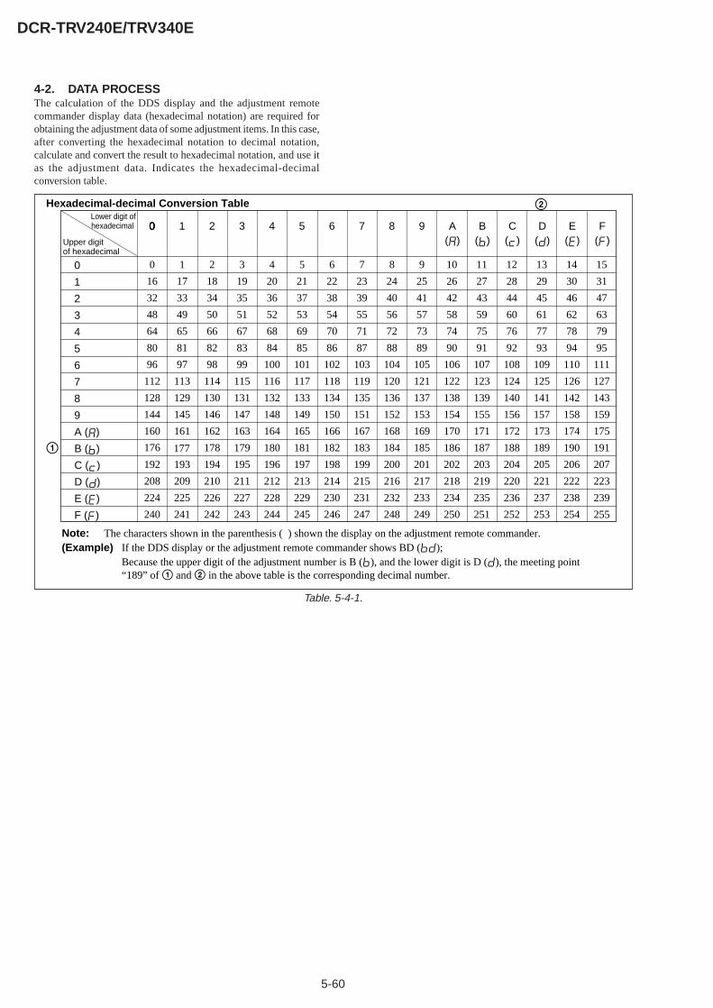
5-60
DCR-TRV240E/TRV340E
4-2. DATA PROCESSThe calculation of the DDS display and the adjustment remotecommander display data (hexadecimal notation) are required forobtaining the adjustment data of some adjustment items. In this case,after converting the hexadecimal notation to decimal notation,calculate and convert the result to hexadecimal notation, and use itas the adjustment data. Indicates the hexadecimal-decimalconversion table.
Hexadecimal-decimal Conversion TableLower digit ofhexadecimal
Upper digit of hexadecimal
0 1 2 3 4 5 6 7 8 9 A(A)
B(b)
C(c)
D(d)
E(E)
F(F)
0
1
2
3
4
5
6
7
8
9
A (A)
B (b)
C (c)
D (d)
E (E)
F (F)
0 1 2 3 4 5 6 7 8 9 10 11 12 13 14 15
16 17 18 19 20 21 22 23 24 25 26 27 28 29 30 31
32 33 34 35 36 37 38 39 40 41 42 43 44 45 46 47
48 49 50 51 52 53 54 55 56 57 58 59 60 61 62 63
64 65 66 67 68 69 70 71 72 73 74 75 76 77 78 79
80 81 82 83 84 85 86 87 88 89 90 91 92 93 94 95
96 97 98 99 100 101 102 103 104 105 106 107 108 109 110 111
112 113 114 115 116 117 118 119 120 121 122 123 124 125 126 127
128 129 130 131 132 133 134 135 136 137 138 139 140 141 142 143
144 145 146 147 148 149 150 151 152 153 154 155 156 157 158
174
159
175160 161 162 163 164 165 166 167 168 169 170 171 172 173
177176 178 179 180 181 182 183 184 185 186 187 188 189 190 191
192 193 194 195 196 197 198 199 200 201 202 203 204 205 206 207
208 209 210 211 212 213 214 215 216 217 218 219 220 221 222 223
224 225 226 227 228 229 230 231 232 233 234 235 236 237 238 239
240 241 242 243 244 245 246 247 248 249 250 251 252 253 254 255
0
1
Note: The characters shown in the parenthesis ( ) shown the display on the adjustment remote commander.(Example) If the DDS display or the adjustment remote commander shows BD (bd);
Because the upper digit of the adjustment number is B (b), and the lower digit is D (d), the meeting point “189” of 1 and 2 in the above table is the corresponding decimal number.
0
2
Table. 5-4-1.
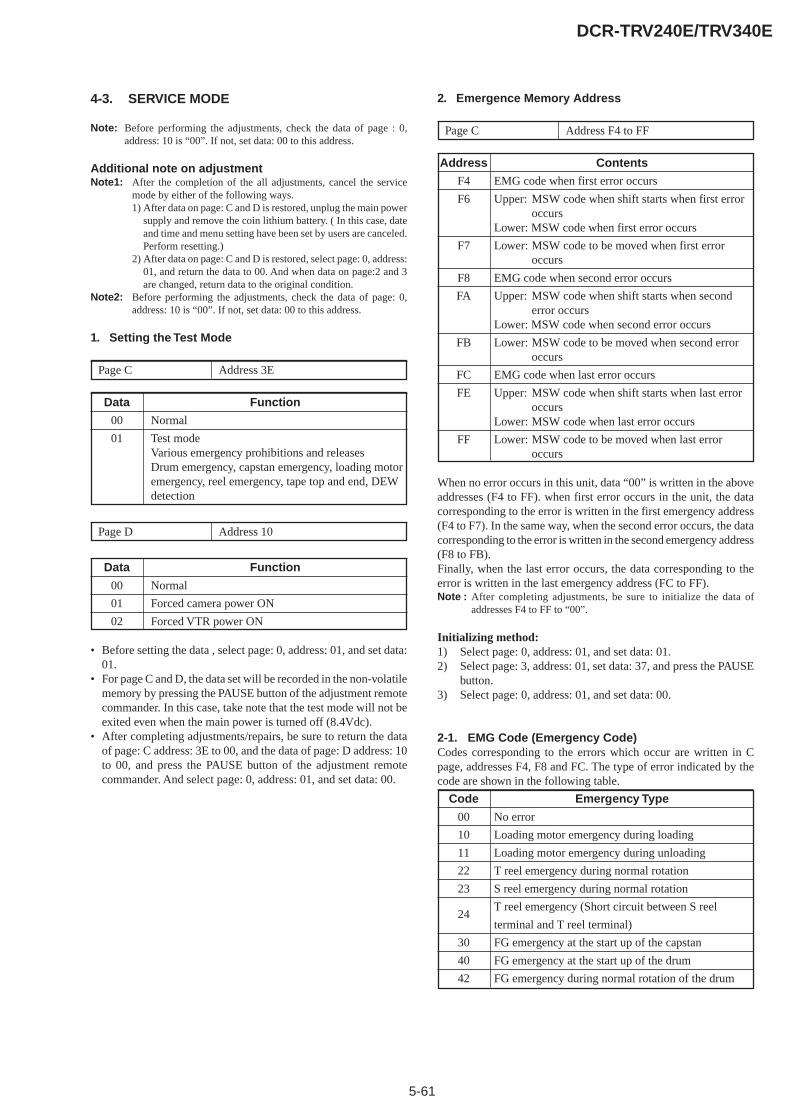
5-61
DCR-TRV240E/TRV340E
4-3. SERVICE MODE
Note: Before performing the adjustments, check the data of page : 0,address: 10 is “00”. If not, set data: 00 to this address.
Additional note on adjustmentNote1: After the completion of the all adjustments, cancel the service
mode by either of the following ways.1) After data on page: C and D is restored, unplug the main power
supply and remove the coin lithium battery. ( In this case, dateand time and menu setting have been set by users are canceled.Perform resetting.)
2) After data on page: C and D is restored, select page: 0, address:01, and return the data to 00. And when data on page:2 and 3are changed, return data to the original condition.
Note2: Before performing the adjustments, check the data of page: 0,address: 10 is “00”. If not, set data: 00 to this address.
1. Setting the Test Mode
Page C Address 3E
Data Function
00 Normal
01 Test modeVarious emergency prohibitions and releasesDrum emergency, capstan emergency, loading motoremergency, reel emergency, tape top and end, DEWdetection
Page D Address 10
Data Function
00 Normal
01 Forced camera power ON
02 Forced VTR power ON
• Before setting the data , select page: 0, address: 01, and set data:01.
• For page C and D, the data set will be recorded in the non-volatilememory by pressing the PAUSE button of the adjustment remotecommander. In this case, take note that the test mode will not beexited even when the main power is turned off (8.4Vdc).
• After completing adjustments/repairs, be sure to return the dataof page: C address: 3E to 00, and the data of page: D address: 10to 00, and press the PAUSE button of the adjustment remotecommander. And select page: 0, address: 01, and set data: 00.
2. Emergence Memory Address
Page C Address F4 to FF
Address Contents
F4 EMG code when first error occurs
F6 Upper: MSW code when shift starts when first erroroccurs
Lower: MSW code when first error occurs
F7 Lower: MSW code to be moved when first erroroccurs
F8 EMG code when second error occurs
FA Upper: MSW code when shift starts when seconderror occurs
Lower: MSW code when second error occurs
FB Lower: MSW code to be moved when second erroroccurs
FC EMG code when last error occurs
FE Upper: MSW code when shift starts when last erroroccurs
Lower: MSW code when last error occurs
FF Lower: MSW code to be moved when last erroroccurs
When no error occurs in this unit, data “00” is written in the aboveaddresses (F4 to FF). when first error occurs in the unit, the datacorresponding to the error is written in the first emergency address(F4 to F7). In the same way, when the second error occurs, the datacorresponding to the error is written in the second emergency address(F8 to FB).Finally, when the last error occurs, the data corresponding to theerror is written in the last emergency address (FC to FF).Note : After completing adjustments, be sure to initialize the data of
addresses F4 to FF to “00”.
Initializing method:1) Select page: 0, address: 01, and set data: 01.2) Select page: 3, address: 01, set data: 37, and press the PAUSE
button.3) Select page: 0, address: 01, and set data: 00.
2-1. EMG Code (Emergency Code)Codes corresponding to the errors which occur are written in Cpage, addresses F4, F8 and FC. The type of error indicated by thecode are shown in the following table.
Code Emergency Type
00 No error
10 Loading motor emergency during loading
11 Loading motor emergency during unloading
22 T reel emergency during normal rotation
23 S reel emergency during normal rotation
24T reel emergency (Short circuit between S reel
terminal and T reel terminal)
30 FG emergency at the start up of the capstan
40 FG emergency at the start up of the drum
42 FG emergency during normal rotation of the drum
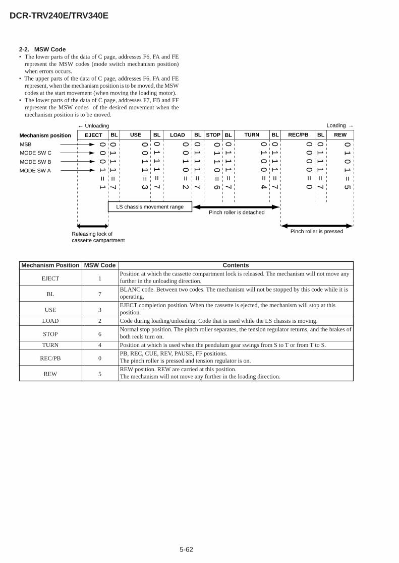
5-62
DCR-TRV240E/TRV340E
00
01
=1
01
11
=7
00
11
=3
00
10
=2
01
11
=7
01
01
=5
01
11
=7
01
11
=7
00
00
=0
01
11
=7
01
00
=4
01
11
=7
01
10
=6
Mechanism position
MODE SW C
MODE SW B
MODE SW A
MSB
← Unloading
Releasing lock of cassette campartment
LS chassis movement range
Pinch roller is pressed
Pinch roller is detached
EJECT BLUSE LOAD BL REWBL BL REC/PB BLTURN BLSTOP
Loading →
ContentsPosition at which the cassette compartment lock is released. The mechanism will not move anyfurther in the unloading direction.
BLANC code. Between two codes. The mechanism will not be stopped by this code while it isoperating.
EJECT completion position. When the cassette is ejected, the mechanism will stop at thisposition.
Code during loading/unloading. Code that is used while the LS chassis is moving.
Normal stop position. The pinch roller separates, the tension regulator returns, and the brakes ofboth reels turn on.
Position at which is used when the pendulum gear swings from S to T or from T to S.
PB, REC, CUE, REV, PAUSE, FF positions.The pinch roller is pressed and tension regulator is on.
REW position. REW are carried at this position.The mechanism will not move any further in the loading direction.
Mechanism Position
EJECT
BL
USE
LOAD
STOP
TURN
REC/PB
REW
MSW Code
1
7
3
2
6
4
0
5
2-2. MSW Code• The lower parts of the data of C page, addresses F6, FA and FE
represent the MSW codes (mode switch mechanism position)when errors occurs.
• The upper parts of the data of C page, addresses F6, FA and FErepresent, when the mechanism position is to be moved, the MSWcodes at the start movement (when moving the loading motor).
• The lower parts of the data of C page, addresses F7, FB and FFrepresent the MSW codes of the desired movement when themechanism position is to be moved.
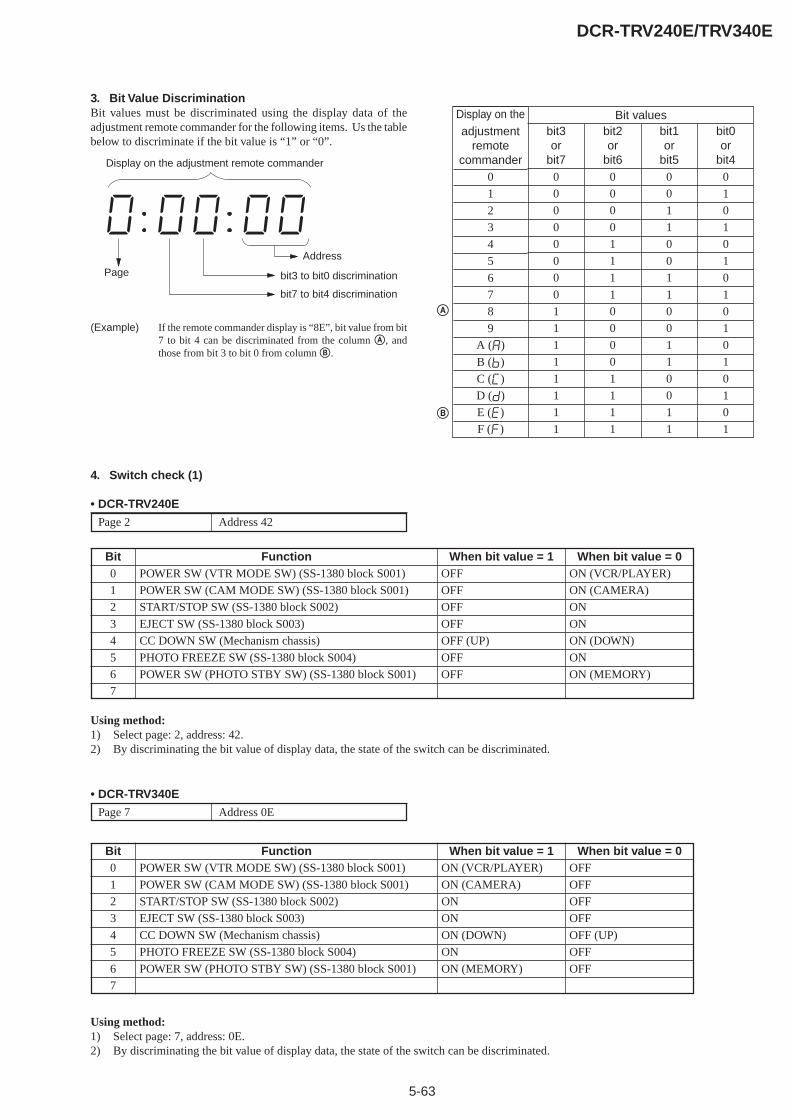
5-63
DCR-TRV240E/TRV340E
3. Bit Value DiscriminationBit values must be discriminated using the display data of theadjustment remote commander for the following items. Us the tablebelow to discriminate if the bit value is “1” or “0”.
(Example) If the remote commander display is “8E”, bit value from bit7 to bit 4 can be discriminated from the column A, andthose from bit 3 to bit 0 from column B.
Page
Address
bit3 to bit0 discrimination
bit7 to bit4 discrimination
Display on the adjustment remote commander
Display on theadjustment
remotecommander
0
1
2
3
4
5
6
7
8
9
A (A)
B (b)
C (C)
D (d)
E (E)
F (F)
Bit valuesbit3or
bit70
0
0
0
0
0
0
0
1
1
1
1
1
1
1
1
bit2or
bit60
0
0
0
1
1
1
1
0
0
0
0
1
1
1
1
bit1or
bit50
0
1
1
0
0
1
1
0
0
1
1
0
0
1
1
bit0or
bit40
1
0
1
0
1
0
1
0
1
0
1
0
1
0
1
A
B
4. Switch check (1)
• DCR-TRV240E
Page 2 Address 42
Using method:1) Select page: 2, address: 42.2) By discriminating the bit value of display data, the state of the switch can be discriminated.
• DCR-TRV340E
Page 7 Address 0E
Using method:1) Select page: 7, address: 0E.2) By discriminating the bit value of display data, the state of the switch can be discriminated.
Bit0
1
2
3
4
5
6
7
FunctionPOWER SW (VTR MODE SW) (SS-1380 block S001)
POWER SW (CAM MODE SW) (SS-1380 block S001)
START/STOP SW (SS-1380 block S002)
EJECT SW (SS-1380 block S003)
CC DOWN SW (Mechanism chassis)
PHOTO FREEZE SW (SS-1380 block S004)
POWER SW (PHOTO STBY SW) (SS-1380 block S001)
When bit value = 1ON (VCR/PLAYER)
ON (CAMERA)
ON
ON
ON (DOWN)
ON
ON (MEMORY)
When bit value = 0OFF
OFF
OFF
OFF
OFF (UP)
OFF
OFF
Bit0
1
2
3
4
5
6
7
FunctionPOWER SW (VTR MODE SW) (SS-1380 block S001)
POWER SW (CAM MODE SW) (SS-1380 block S001)
START/STOP SW (SS-1380 block S002)
EJECT SW (SS-1380 block S003)
CC DOWN SW (Mechanism chassis)
PHOTO FREEZE SW (SS-1380 block S004)
POWER SW (PHOTO STBY SW) (SS-1380 block S001)
When bit value = 1OFF
OFF
OFF
OFF
OFF (UP)
OFF
OFF
When bit value = 0ON (VCR/PLAYER)
ON (CAMERA)
ON
ON
ON (DOWN)
ON
ON (MEMORY)

5-64
DCR-TRV240E/TRV340E
5. Switch check (2)
• DCR-TRV240E
Page 2 Address 81
Using method:1) Select page: 2, address: 81.2) By discriminating the bit value of display data, the state of the switch can be discriminated.
• DCR-TRV340E
Page 7 Address 0C
Using method:1) Select page: 7, address: 0C.2) By discriminating the bit value of display data, the state of the switch can be discriminated.
6. Switch check (3)
Page 3 Address 61
Using method:1) Select page: 3, address: 61.2) By discriminating the bit value of display data, the state of the switch can be discriminated.
Bit4
5
6
FunctionAUDIO/VIDEO jack (FP-410 flexible J201)
S VIDEO jack (FP-410 flexible J201)
MIC jack (FP-411 flexible J302)
When bit value = 1Used
Not used
Used
When bit value = 0Not used
Used
Not used
Bit1
2
3
FunctionAUDIO/VIDEO jack (FP-410 flexible J201)
S VIDEO jack (FP-410 flexible J201)
MIC jack (FP-411 flexible J302)
When bit value = 1Used
Used
Used
When bit value = 0Not used
Not used
Not used
Bit6
FunctionHEADPHONS jack (FP-411 flexible J301)
When bit value = 1Used
When bit value = 0Not used
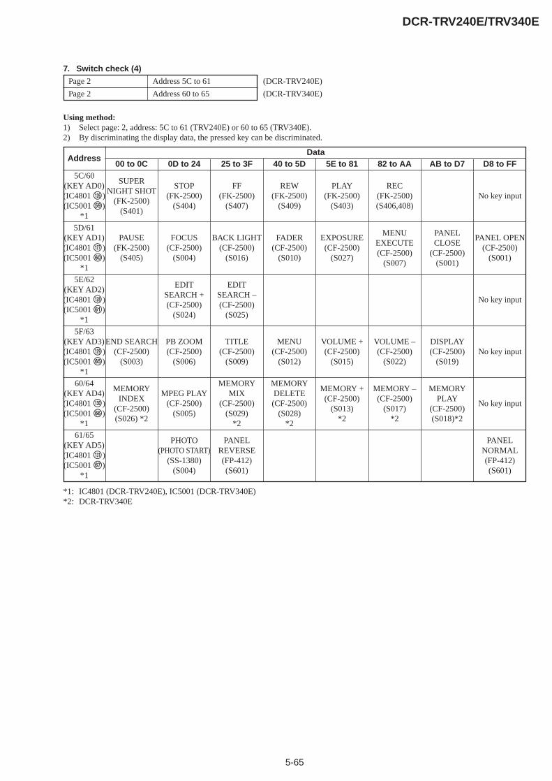
5-65
DCR-TRV240E/TRV340E
7. Switch check (4)
Page 2 Address 5C to 61 (DCR-TRV240E)
Page 2 Address 60 to 65 (DCR-TRV340E)
Using method:1) Select page: 2, address: 5C to 61 (TRV240E) or 60 to 65 (TRV340E).2) By discriminating the display data, the pressed key can be discriminated.
*1: IC4801 (DCR-TRV240E), IC5001 (DCR-TRV340E)*2: DCR-TRV340E
Address
5C/60(KEY AD0)(IC4801 <zxn )(IC5001 tl)
*1
5D/61(KEY AD1)(IC4801 <zxm )(IC5001 y;)
*1
5E/62(KEY AD2)(IC4801 <zx, )(IC5001 ya)
*1
5F/63(KEY AD3)(IC4801 <zx. )(IC5001 yg)
*1
60/64(KEY AD4)(IC4801 <zc/ )(IC5001 yh)
*1
61/65(KEY AD5)(IC4801 <zcz )(IC5001 yj)
*1
00 to 0C
SUPERNIGHT SHOT
(FK-2500)(S401)
PAUSE(FK-2500)
(S405)
END SEARCH(CF-2500)
(S003)
MEMORYINDEX
(CF-2500)(S026) *2
0D to 24
STOP(FK-2500)
(S404)
FOCUS(CF-2500)
(S004)
EDITSEARCH +(CF-2500)
(S024)
PB ZOOM(CF-2500)
(S006)
MPEG PLAY(CF-2500)
(S005)
PHOTO(PHOTO START)
(SS-1380)(S004)
25 to 3F
FF(FK-2500)
(S407)
BACK LIGHT(CF-2500)
(S016)
EDITSEARCH –(CF-2500)
(S025)
TITLE(CF-2500)
(S009)
MEMORYMIX
(CF-2500)(S029)
*2
PANELREVERSE(FP-412)(S601)
40 to 5D
REW(FK-2500)
(S409)
FADER(CF-2500)
(S010)
MENU(CF-2500)
(S012)
MEMORYDELETE(CF-2500)
(S028)*2
5E to 81
PLAY(FK-2500)
(S403)
EXPOSURE(CF-2500)
(S027)
VOLUME +(CF-2500)
(S015)
MEMORY +(CF-2500)
(S013)*2
82 to AA
REC(FK-2500)(S406,408)
MENUEXECUTE(CF-2500)
(S007)
VOLUME –(CF-2500)
(S022)
MEMORY –(CF-2500)
(S017)*2
DataAB to D7
PANELCLOSE
(CF-2500)(S001)
DISPLAY(CF-2500)
(S019)
MEMORYPLAY
(CF-2500)(S018)*2
D8 to FF
No key input
PANEL OPEN(CF-2500)
(S001)
No key input
No key input
No key input
PANELNORMAL(FP-412)(S601)
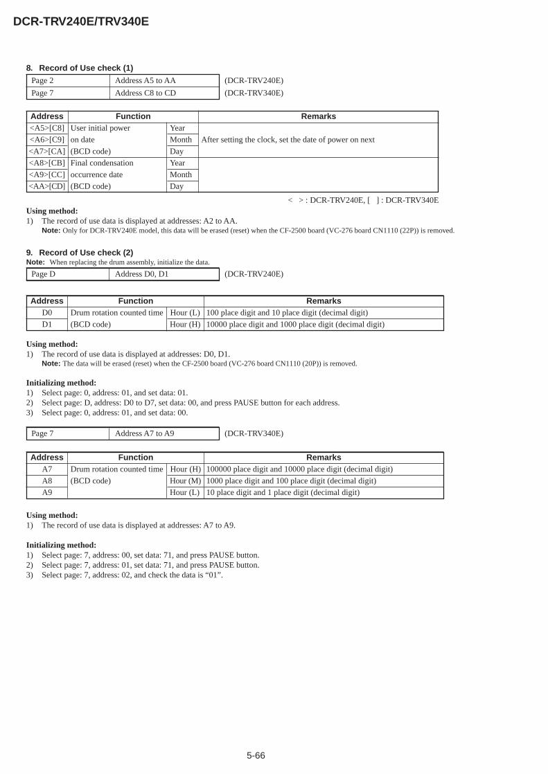
5-66
DCR-TRV240E/TRV340E
8. Record of Use check (1)
Page 2 Address A5 to AA (DCR-TRV240E)
Page 7 Address C8 to CD (DCR-TRV340E)
Using method:1) The record of use data is displayed at addresses: A2 to AA.
Note: Only for DCR-TRV240E model, this data will be erased (reset) when the CF-2500 board (VC-276 board CN1110 (22P)) is removed.
Address<A5>[C8]
<A6>[C9]
<A7>[CA]
<A8>[CB]
<A9>[CC]
<AA>[CD]
FunctionUser initial power Year
on date Month
(BCD code) Day
Final condensation Year
occurrence date Month
(BCD code) Day
Remarks
After setting the clock, set the date of power on next
< > : DCR-TRV240E, [ ] : DCR-TRV340E
9. Record of Use check (2)Note: When replacing the drum assembly, initialize the data.
Page D Address D0, D1 (DCR-TRV240E)
Using method:1) The record of use data is displayed at addresses: D0, D1.
Note: The data will be erased (reset) when the CF-2500 board (VC-276 board CN1110 (20P)) is removed.
Initializing method:1) Select page: 0, address: 01, and set data: 01.2) Select page: D, address: D0 to D7, set data: 00, and press PAUSE button for each address.3) Select page: 0, address: 01, and set data: 00.
AddressD0
D1
FunctionDrum rotation counted time Hour (L)
(BCD code) Hour (H)
Remarks100 place digit and 10 place digit (decimal digit)
10000 place digit and 1000 place digit (decimal digit)
Using method:1) The record of use data is displayed at addresses: A7 to A9.
Initializing method:1) Select page: 7, address: 00, set data: 71, and press PAUSE button.2) Select page: 7, address: 01, set data: 71, and press PAUSE button.3) Select page: 7, address: 02, and check the data is “01”.
AddressA7
A8
A9
FunctionDrum rotation counted time Hour (H)
(BCD code) Hour (M)
Hour (L)
Remarks100000 place digit and 10000 place digit (decimal digit)
1000 place digit and 100 place digit (decimal digit)
10 place digit and 1 place digit (decimal digit)
Page 7 Address A7 to A9 (DCR-TRV340E)
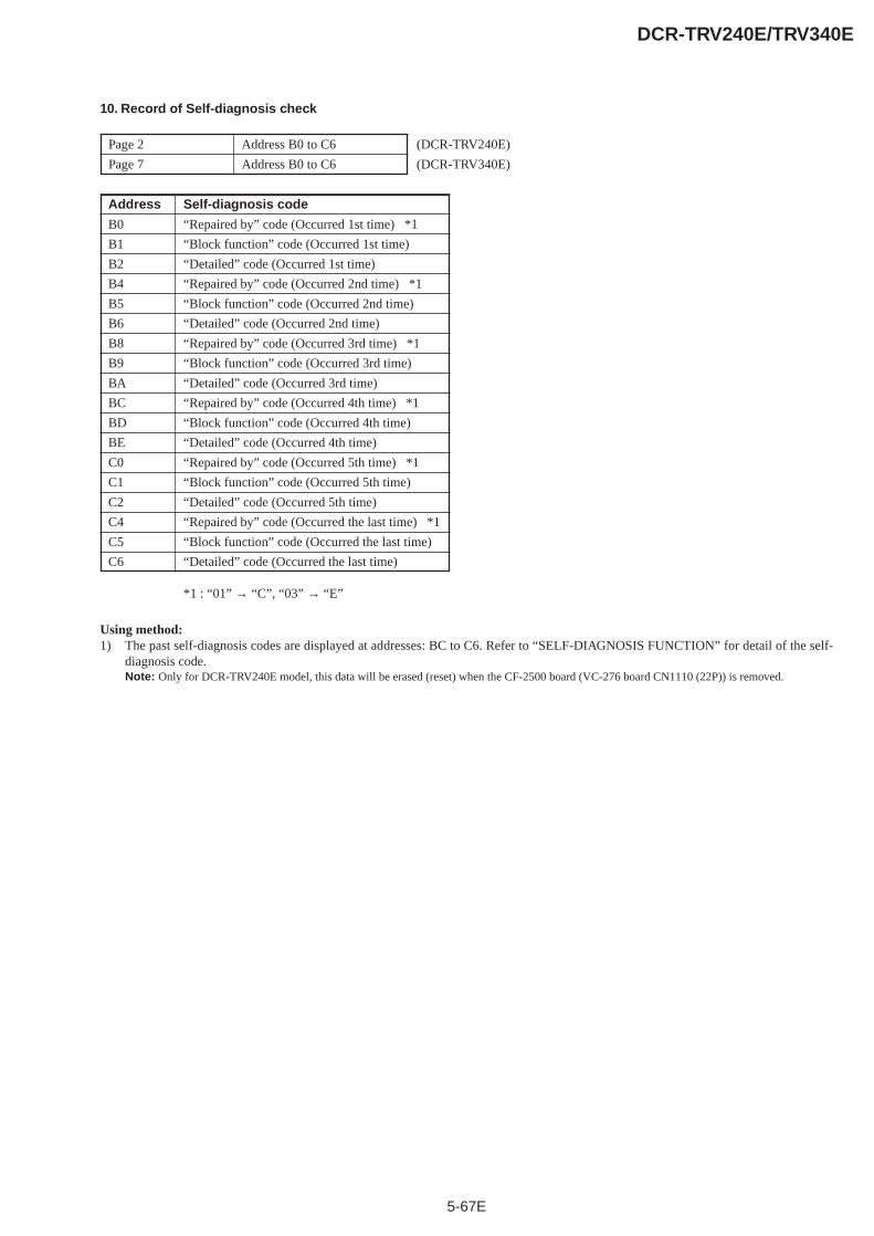
5-67E
DCR-TRV240E/TRV340E
10. Record of Self-diagnosis check
Page 2 Address B0 to C6 (DCR-TRV240E)
Page 7 Address B0 to C6 (DCR-TRV340E)
Address Self-diagnosis code
B0 “Repaired by” code (Occurred 1st time) *1
B1 “Block function” code (Occurred 1st time)
B2 “Detailed” code (Occurred 1st time)
B4 “Repaired by” code (Occurred 2nd time) *1
B5 “Block function” code (Occurred 2nd time)
B6 “Detailed” code (Occurred 2nd time)
B8 “Repaired by” code (Occurred 3rd time) *1
B9 “Block function” code (Occurred 3rd time)
BA “Detailed” code (Occurred 3rd time)
BC “Repaired by” code (Occurred 4th time) *1
BD “Block function” code (Occurred 4th time)
BE “Detailed” code (Occurred 4th time)
C0 “Repaired by” code (Occurred 5th time) *1
C1 “Block function” code (Occurred 5th time)
C2 “Detailed” code (Occurred 5th time)
C4 “Repaired by” code (Occurred the last time) *1
C5 “Block function” code (Occurred the last time)
C6 “Detailed” code (Occurred the last time)
*1 : “01” → “C”, “03” → “E”
Using method:1) The past self-diagnosis codes are displayed at addresses: BC to C6. Refer to “SELF-DIAGNOSIS FUNCTION” for detail of the self-
diagnosis code.Note: Only for DCR-TRV240E model, this data will be erased (reset) when the CF-2500 board (VC-276 board CN1110 (22P)) is removed.
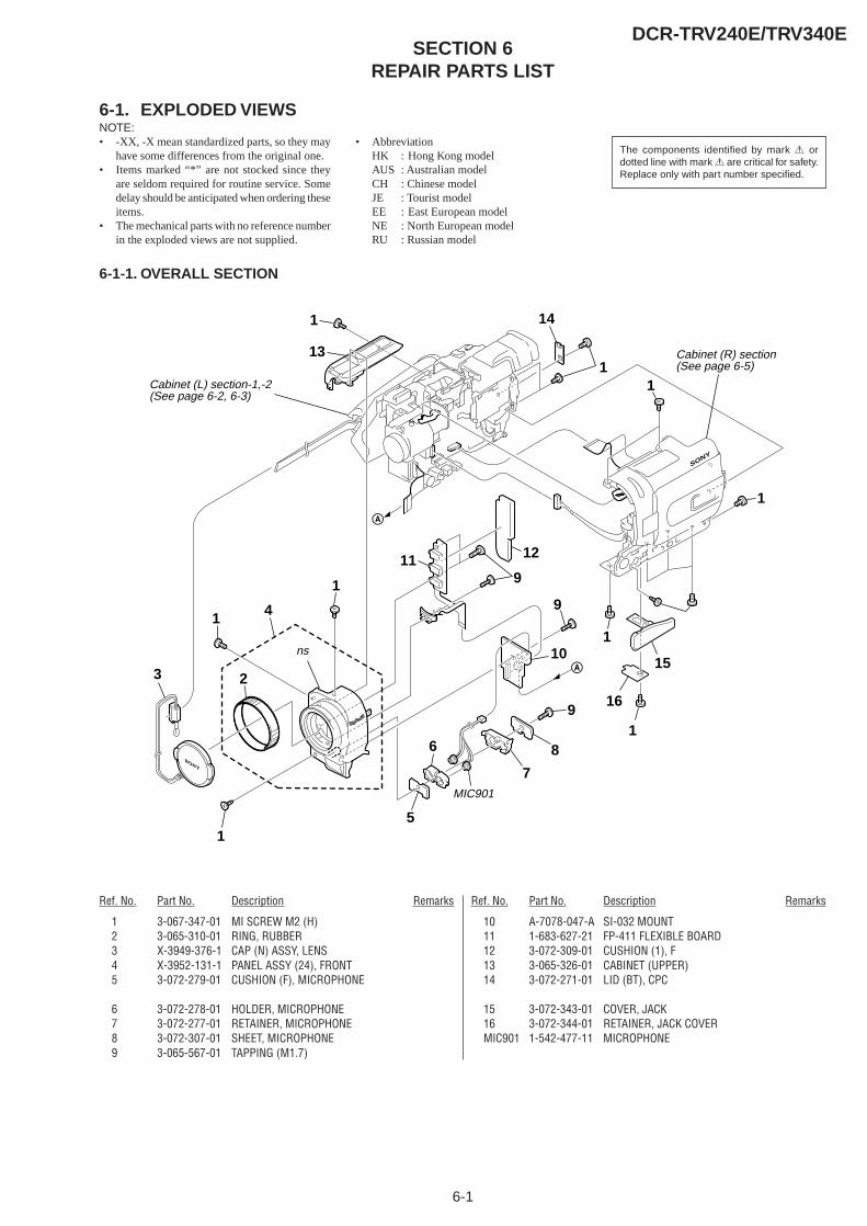
6-1
DCR-TRV240E/TRV340ESECTION 6
REPAIR PARTS LIST
6-1. EXPLODED VIEWSNOTE:• -XX, -X mean standardized parts, so they may
have some differences from the original one.• Items marked “*” are not stocked since they
are seldom required for routine service. Somedelay should be anticipated when ordering theseitems.
• The mechanical parts with no reference numberin the exploded views are not supplied.
• AbbreviationHK : Hong Kong modelAUS : Australian modelCH : Chinese modelJE : Tourist modelEE : East European modelNE : North European modelRU : Russian model
The components identified by mark 0 ordotted line with mark 0 are critical for safety.Replace only with part number specified.
6-1-1. OVERALL SECTION
Ref. No. Part No. Description Remarks Ref. No. Part No. Description Remarks
SONY
A
A
Cabinet (R) section(See page 6-5)
Cabinet (L) section-1,-2 (See page 6-2, 6-3)
ns
1
1
2
4
1
1
3
5
6
MIC901
7
8
9
9
911
13
12
10
14
1
11
1
16
1
15
1 3-067-347-01 MI SCREW M2 (H)2 3-065-310-01 RING, RUBBER3 X-3949-376-1 CAP (N) ASSY, LENS4 X-3952-131-1 PANEL ASSY (24), FRONT5 3-072-279-01 CUSHION (F), MICROPHONE
6 3-072-278-01 HOLDER, MICROPHONE7 3-072-277-01 RETAINER, MICROPHONE8 3-072-307-01 SHEET, MICROPHONE9 3-065-567-01 TAPPING (M1.7)
10 A-7078-047-A SI-032 MOUNT11 1-683-627-21 FP-411 FLEXIBLE BOARD12 3-072-309-01 CUSHION (1), F13 3-065-326-01 CABINET (UPPER)14 3-072-271-01 LID (BT), CPC
15 3-072-343-01 COVER, JACK16 3-072-344-01 RETAINER, JACK COVERMIC901 1-542-477-11 MICROPHONE
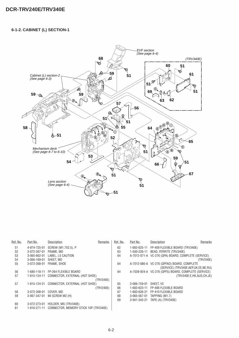
6-2
DCR-TRV240E/TRV340E
6-1-2. CABINET (L) SECTION-1
VC-276
Board
I
EF
GH
E
D
FG
HI
D
C
BA
A
C
Lens section(See page 6-4)
Mechanism deck(See page 6-7 to 6-10)
(TRV340E)
Cabinet (L) section-2 (See page 6-3)
EVF section (See page 6-4)
51
51
5354
51
58
51
66
67
B
59 59
68
59
5951
51
5160
51
61
51
5151
51
65
64
5756
55
52
6263
69
Ref. No. Part No. Description Remarks Ref. No. Part No. Description Remarks
51 4-974-725-01 SCREW (M1.7X2.5), P52 3-072-267-01 FRAME, MD53 3-065-662-01 LABEL, LS CAUTION54 3-066-169-01 SHEET, MD55 3-072-268-01 FRAME, SHOE
56 1-680-118-11 FP-264 FLEXIBLE BOARD57 1-815-124-11 CONNECTOR, EXTERNAL (HOT SHOE)
(TRV340E)57 1-815-124-21 CONNECTOR, EXTERNAL (HOT SHOE)
(TRV240E)58 3-072-308-01 COVER, MD59 3-067-347-01 MI SCREW M2 (H)
60 3-072-273-01 HOLDER, MS (TRV340E)61 1-816-271-11 CONNECTOR, MEMORY STICK 10P (TRV340E)
62 1-683-625-11 FP-409 FLEXIBLE BOARD (TRV340E)63 1-500-226-11 BEAD, FERRITE (TRV340E)64 A-7012-071-A VC-276 (QPA) BOARD, COMPLETE (SERVICE)
(TRV240E)64 A-7012-080-A VC-276 (QPFAO) BOARD, COMPLETE
(SERVICE) (TRV340E:AEP,UK,EE,NE,RU)64 A-7028-924-A VC-276 (QPFS) BOARD, COMPLETE (SERVICE)
(TRV340E:E,HK,AUS,CH,JE)
65 3-066-759-01 SHEET, VC66 1-683-623-11 FP-406 FLEXIBLE BOARD67 1-683-626-21 FP-410 FLEXIBLE BOARD68 3-065-567-01 TAPPING (M1.7)69 3-941-343-21 TAPE (A) (TRV340E)
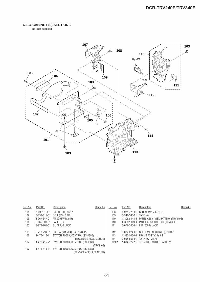
6-3
DCR-TRV240E/TRV340E
6-1-3. CABINET (L) SECTION-2
A
A
ns
ns
ns
103
108
102
103
114
107
110
111
109
112
105
104103
101
103
BT901
106
113
Ref. No. Part No. Description Remarks Ref. No. Part No. Description Remarks
101 X-3951-159-1 CABINET (L) ASSY102 3-052-815-01 BELT (ES), GRIP103 3-067-347-01 MI SCREW M2 (H)104 3-065-308-01 LABEL (L)105 3-978-765-01 SLIDER, G LOCK
106 3-713-791-01 SCREW (M1.7X4), TAPPING, P2107 1-476-415-11 SWITCH BLOCK, CONTROL (SS-1380)
(TRV340E:E,HK,AUS,CH,JE)107 1-476-415-21 SWITCH BLOCK, CONTROL (SS-1380)
(TRV240E)107 1-476-415-31 SWITCH BLOCK, CONTROL (SS-1380)
(TRV340E:AEP,UK,EE,NE,RU)
108 4-974-725-01 SCREW (M1.7X2.5), P109 3-941-343-21 TAPE (A)110 X-3952-148-1 PANEL ASSY (MS), BATTERY (TRV340E)110 X-3952-149-1 PANEL ASSY, BATTERY (TRV240E)111 3-072-305-01 LID (2500), JACK
112 3-072-274-01 SHEET METAL (LOWER), STRAP113 X-3952-136-1 FRAME ASSY (25), CS114 3-065-567-01 TAPPING (M1.7)BT901 1-694-772-11 TERMINAL BOARD, BATTERY
ns : not supplied
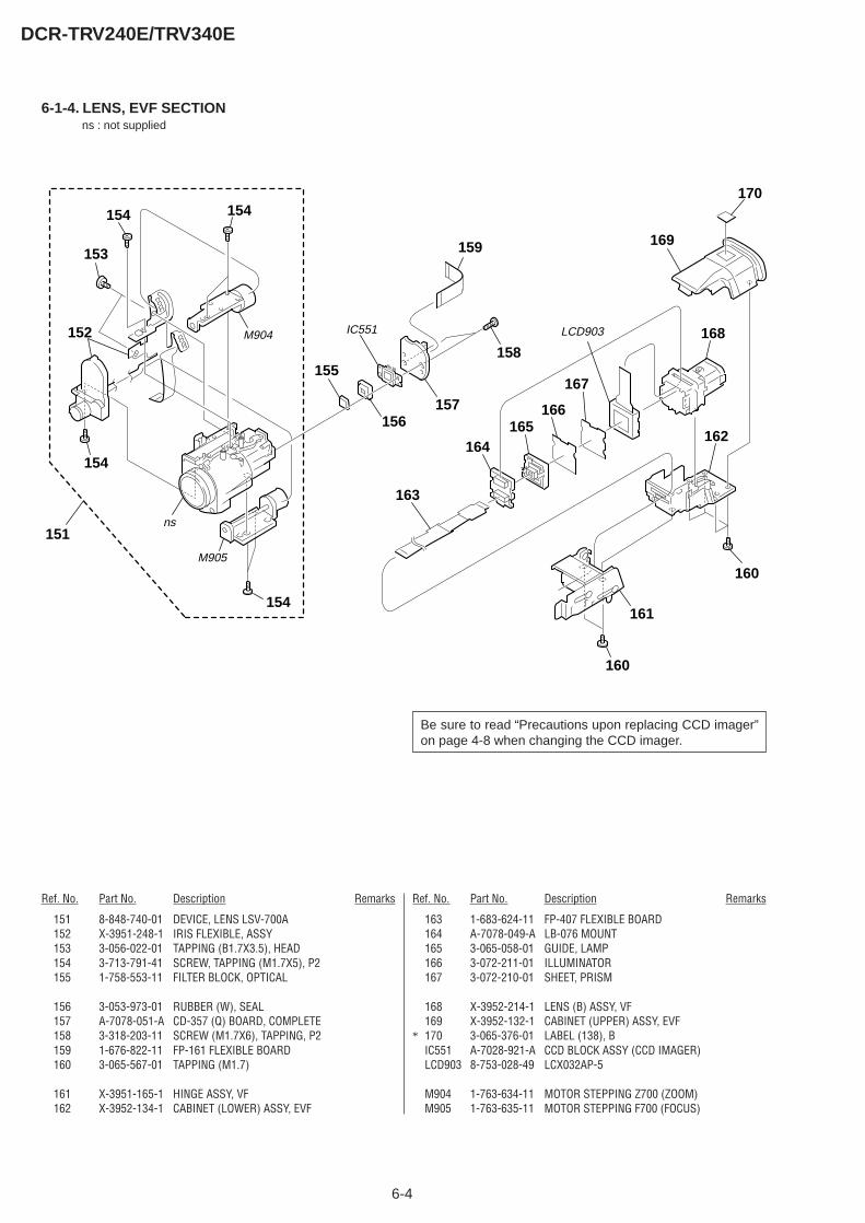
6-4
DCR-TRV240E/TRV340E
6-1-4. LENS, EVF SECTION
M905
ns
157156
155
153
154
152
154
160
162
160
161154
154
IC551M904
158
159
151
163
164
167
165
168
166
169
170
LCD903
Ref. No. Part No. Description Remarks Ref. No. Part No. Description Remarks
Be sure to read “Precautions upon replacing CCD imager”on page 4-8 when changing the CCD imager.
151 8-848-740-01 DEVICE, LENS LSV-700A152 X-3951-248-1 IRIS FLEXIBLE, ASSY153 3-056-022-01 TAPPING (B1.7X3.5), HEAD154 3-713-791-41 SCREW, TAPPING (M1.7X5), P2155 1-758-553-11 FILTER BLOCK, OPTICAL
156 3-053-973-01 RUBBER (W), SEAL157 A-7078-051-A CD-357 (Q) BOARD, COMPLETE158 3-318-203-11 SCREW (M1.7X6), TAPPING, P2159 1-676-822-11 FP-161 FLEXIBLE BOARD160 3-065-567-01 TAPPING (M1.7)
161 X-3951-165-1 HINGE ASSY, VF162 X-3952-134-1 CABINET (LOWER) ASSY, EVF
163 1-683-624-11 FP-407 FLEXIBLE BOARD164 A-7078-049-A LB-076 MOUNT165 3-065-058-01 GUIDE, LAMP166 3-072-211-01 ILLUMINATOR167 3-072-210-01 SHEET, PRISM
168 X-3952-214-1 LENS (B) ASSY, VF169 X-3952-132-1 CABINET (UPPER) ASSY, EVF
* 170 3-065-376-01 LABEL (138), BIC551 A-7028-921-A CCD BLOCK ASSY (CCD IMAGER)LCD903 8-753-028-49 LCX032AP-5
M904 1-763-634-11 MOTOR STEPPING Z700 (ZOOM)M905 1-763-635-11 MOTOR STEPPING F700 (FOCUS)
ns : not supplied
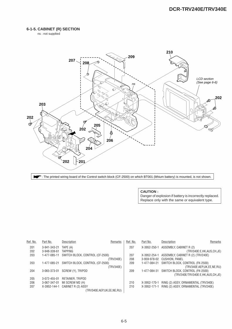
6-5
DCR-TRV240E/TRV340E
6-1-5. CABINET (R) SECTION
ns
LCD section (See page 6-6)
201202
202
202
206
205
202
204
207209
210
208
203
: The printed wiring board of the Control switch block (CF-2500) on which BT001 (lithium battery) is mounted, is not shown.
Ref. No. Part No. Description Remarks Ref. No. Part No. Description Remarks
CAUTION :Danger of explosion if battery is incorrectly replaced.Replace only with the same or equivalent type.
201 3-941-343-21 TAPE (A)202 3-948-339-61 TAPPING203 1-477-085-11 SWITCH BLOCK, CONTROL (CF-2500)
(TRV240E)203 1-477-085-21 SWITCH BLOCK, CONTROL (CF-2500)
(TRV340E)204 3-065-373-01 SCREW (Y), TRIPOD
205 3-072-455-01 RETAINER, TRIPOD206 3-067-347-01 MI SCREW M2 (H)207 X-3952-144-1 CABINET R (2) ASSY
(TRV340E:AEP,UK,EE,NE,RU)
207 X-3952-250-1 ASSEMBLY, CABINET R (2)(TRV340E:E,HK,AUS,CH,JE)
207 X-3952-254-1 ASSEMBLY, CABINET R (2) (TRV240E)208 3-959-978-02 CUSHION, PANEL209 1-477-084-21 SWITCH BLOCK, CONTROL (FK-2500)
(TRV340E:AEP,UK,EE,NE,RU)209 1-477-084-31 SWITCH BLOCK, CONTROL (FK-2500)
(TRV240E/TRV340E:E,HK,AUS,CH,JE)
210 X-3952-170-1 RING (2) ASSY, ORNAMENTAL (TRV340E)210 X-3952-171-1 RING (2) ASSY, ORNAMENTAL (TRV240E)
ns : not supplied
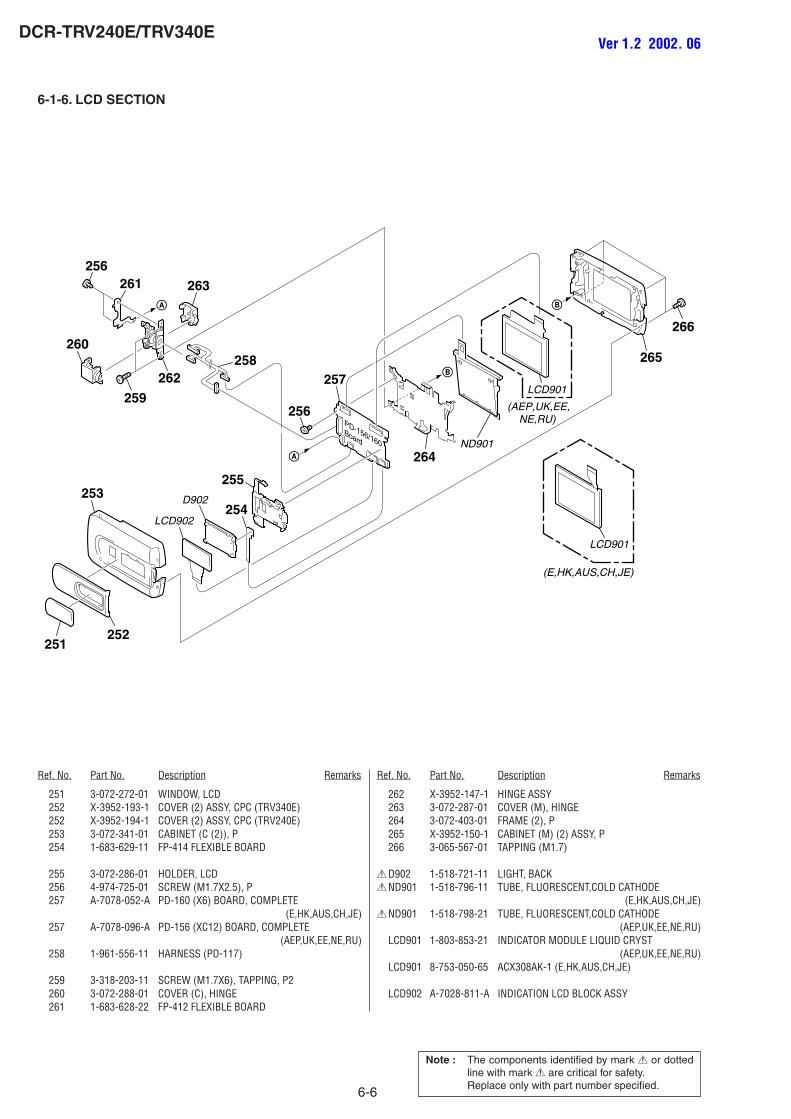
6-6
DCR-TRV240E/TRV340E
6-1-6. LCD SECTION
PD-156/160Board
A
A
B
B
D902
LCD902
251252
253254
255
258
263
259
260
262
261256
256
257
264ND901
265
266
LCD901
(E,HK,AUS,CH,JE)
LCD901
(AEP,UK,EE, NE,RU)
Ref. No. Part No. Description Remarks Ref. No. Part No. Description Remarks
Note : The components identified by mark 0 or dottedline with mark 0 are critical for safety.Replace only with part number specified.
251 3-072-272-01 WINDOW, LCD252 X-3952-193-1 COVER (2) ASSY, CPC (TRV340E)252 X-3952-194-1 COVER (2) ASSY, CPC (TRV240E)253 3-072-341-01 CABINET (C (2)), P254 1-683-629-11 FP-414 FLEXIBLE BOARD
255 3-072-286-01 HOLDER, LCD256 4-974-725-01 SCREW (M1.7X2.5), P257 A-7078-052-A PD-160 (X6) BOARD, COMPLETE
(E,HK,AUS,CH,JE)257 A-7078-096-A PD-156 (XC12) BOARD, COMPLETE
(AEP,UK,EE,NE,RU)258 1-961-556-11 HARNESS (PD-117)
259 3-318-203-11 SCREW (M1.7X6), TAPPING, P2260 3-072-288-01 COVER (C), HINGE261 1-683-628-22 FP-412 FLEXIBLE BOARD
262 X-3952-147-1 HINGE ASSY263 3-072-287-01 COVER (M), HINGE264 3-072-403-01 FRAME (2), P265 X-3952-150-1 CABINET (M) (2) ASSY, P266 3-065-567-01 TAPPING (M1.7)
0D902 1-518-721-11 LIGHT, BACK0ND901 1-518-796-11 TUBE, FLUORESCENT,COLD CATHODE
(E,HK,AUS,CH,JE)0ND901 1-518-798-21 TUBE, FLUORESCENT,COLD CATHODE
(AEP,UK,EE,NE,RU)LCD901 1-803-853-21 INDICATOR MODULE LIQUID CRYST
(AEP,UK,EE,NE,RU)LCD901 8-753-050-65 ACX308AK-1 (E,HK,AUS,CH,JE)
LCD902 A-7028-811-A INDICATION LCD BLOCK ASSY
Ver 1.2 2002. 06
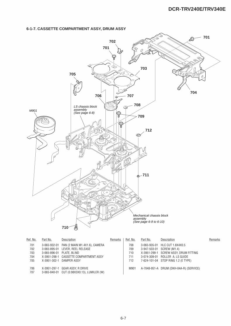
6-7
DCR-TRV240E/TRV340E
6-1-7. CASSETTE COMPARTMENT ASSY, DRUM ASSY
701
704
701
703
707
708
709
706
702
705
710
M901LS chassis blockassembly(See page 6-8)
Mechanical chassis blockassembly(See page 6-9 to 6-10)
712
711
Ref. No. Part No. Description Remarks Ref. No. Part No. Description Remarks
701 3-065-932-01 PAN (2 MAIN M1.4X1.6), CAMERA702 3-065-895-01 LEVER, REEL RELEASE703 3-065-896-01 PLATE, BLIND704 X-3951-298-1 CASSETTE COMPARTMENT ASSY705 X-3951-302-1 DAMPER ASSY
706 X-3951-297-1 GEAR ASSY, R DRIVE707 3-065-840-01 CUT (0.98X3X0.13), LUMILER (W)
708 3-065-935-01 HLC CUT 1.8X4X0.5709 3-947-503-01 SCREW (M1.4)710 X-3951-299-1 SCREW ASSY, DRUM FITTING711 3-074-309-01 ROLLER A, LS GUIDE712 7-624-101-04 STOP RING 1.2 (E TYPE)
M901 A-7048-951-A DRUM (DKH-04A-R) (SERVICE)
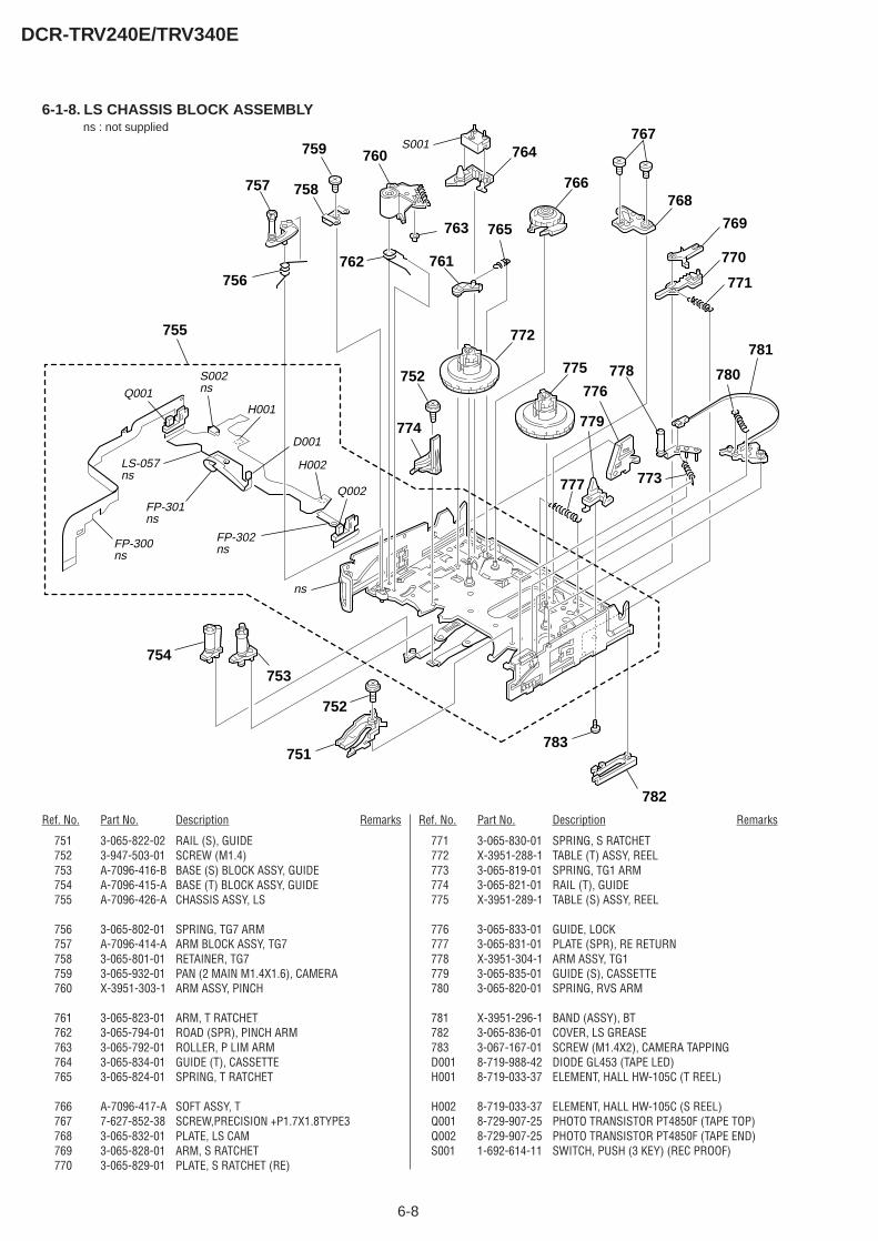
6-8
DCR-TRV240E/TRV340E
6-1-8. LS CHASSIS BLOCK ASSEMBLY
782
751
753
757
754
783
752
752
774
777
776778
779
759
758
760
765
756762
764
763
761
766
772
775
769
768
770
771
781
773
780
767
755
ns
FP-300ns
LS-057ns
S002ns
FP-301ns
FP-302ns
H001
H002
D001
S001
Q001
Q002
Ref. No. Part No. Description Remarks Ref. No. Part No. Description Remarks
751 3-065-822-02 RAIL (S), GUIDE752 3-947-503-01 SCREW (M1.4)753 A-7096-416-B BASE (S) BLOCK ASSY, GUIDE754 A-7096-415-A BASE (T) BLOCK ASSY, GUIDE755 A-7096-426-A CHASSIS ASSY, LS
756 3-065-802-01 SPRING, TG7 ARM757 A-7096-414-A ARM BLOCK ASSY, TG7758 3-065-801-01 RETAINER, TG7759 3-065-932-01 PAN (2 MAIN M1.4X1.6), CAMERA760 X-3951-303-1 ARM ASSY, PINCH
761 3-065-823-01 ARM, T RATCHET762 3-065-794-01 ROAD (SPR), PINCH ARM763 3-065-792-01 ROLLER, P LIM ARM764 3-065-834-01 GUIDE (T), CASSETTE765 3-065-824-01 SPRING, T RATCHET
766 A-7096-417-A SOFT ASSY, T767 7-627-852-38 SCREW,PRECISION +P1.7X1.8TYPE3768 3-065-832-01 PLATE, LS CAM769 3-065-828-01 ARM, S RATCHET770 3-065-829-01 PLATE, S RATCHET (RE)
771 3-065-830-01 SPRING, S RATCHET772 X-3951-288-1 TABLE (T) ASSY, REEL773 3-065-819-01 SPRING, TG1 ARM774 3-065-821-01 RAIL (T), GUIDE775 X-3951-289-1 TABLE (S) ASSY, REEL
776 3-065-833-01 GUIDE, LOCK777 3-065-831-01 PLATE (SPR), RE RETURN778 X-3951-304-1 ARM ASSY, TG1779 3-065-835-01 GUIDE (S), CASSETTE780 3-065-820-01 SPRING, RVS ARM
781 X-3951-296-1 BAND (ASSY), BT782 3-065-836-01 COVER, LS GREASE783 3-067-167-01 SCREW (M1.4X2), CAMERA TAPPINGD001 8-719-988-42 DIODE GL453 (TAPE LED)H001 8-719-033-37 ELEMENT, HALL HW-105C (T REEL)
H002 8-719-033-37 ELEMENT, HALL HW-105C (S REEL)Q001 8-729-907-25 PHOTO TRANSISTOR PT4850F (TAPE TOP)Q002 8-729-907-25 PHOTO TRANSISTOR PT4850F (TAPE END)S001 1-692-614-11 SWITCH, PUSH (3 KEY) (REC PROOF)
ns : not supplied

6-9
DCR-TRV240E/TRV340E
6-1-9. MECHANICAL CHASSIS BLOCK ASSEMBLY-1
805
810
802809
802
815
824
817
819
802
823
820 821
822
815
818
816811
805
807
815
814
813
812
806
801
803
804
808
M902
M903
Mechanical chassis block assembly-2(See page 6-10)
ns
Ref. No. Part No. Description Remarks Ref. No. Part No. Description Remarks
801 A-7096-422-A BASE ASSY, DRUM802 3-947-503-01 SCREW (M1.4)803 3-065-928-01 SPACER, GROUND804 3-065-927-01 GROUND, DRUM805 3-065-932-01 PAN (2 MAIN M1.4X1.6), CAMERA
806 3-067-154-01 SPRING, CAPSTAN807 3-065-931-01 RAIL (T2), GUIDE808 X-3947-398-1 SCREW ASSY, M1.7 PW809 3-065-933-01 PAN (2 MAIN 1.4X4.5), CAMERA810 1-677-049-11 FP-228 FLEXIBLE BOARD (DEW SENSOR)
811 1-680-434-11 FP-299 FLEXIBLE BOARD812 3-065-877-01 PLATE (T), GUIDE LOCK813 X-3951-301-1 PLATE ASSY, PINCH PRESSURE
814 3-065-881-01 SPRING, P PRESSURE PLATE815 3-065-934-01 HLW CUT 0.98X3X0.25816 1-786-096-11 SWITCH, ROTARY817 3-065-898-01 SPRING, EJECT ARM818 3-065-870-01 ROLLER, LS GUIDE
819 A-7096-421-A ARM ASSY, HCL820 3-065-918-01 GEAR (2), CAM RELAY821 A-7096-419-A GEAR ASSY, CHANGE822 3-065-902-01 BELT, TIMING823 3-065-905-01 GEAR, RELAY
824 3-065-882-01 ARM, EJECTM902 8-835-701-01 MOTOR, DC SCE13A/C-NP (CAPSTAN)M903 A-7096-420-A MOTOR ASSY, LD (LOADING)
ns : not supplied
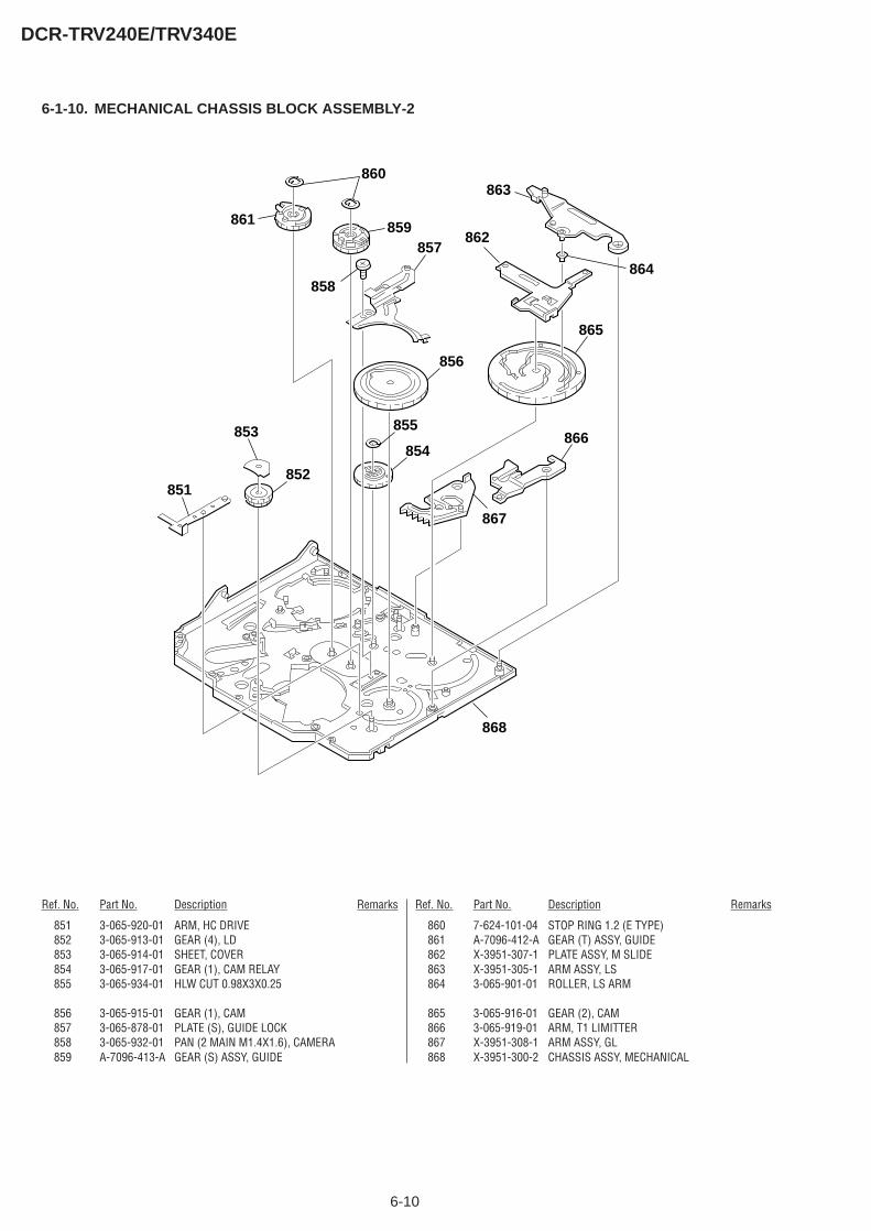
6-10
DCR-TRV240E/TRV340E
6-1-10. MECHANICAL CHASSIS BLOCK ASSEMBLY-2
852
855
856
858
857
860
859861
865
866
867
854
868
851
853
862
864
863
Ref. No. Part No. Description Remarks Ref. No. Part No. Description Remarks
851 3-065-920-01 ARM, HC DRIVE852 3-065-913-01 GEAR (4), LD853 3-065-914-01 SHEET, COVER854 3-065-917-01 GEAR (1), CAM RELAY855 3-065-934-01 HLW CUT 0.98X3X0.25
856 3-065-915-01 GEAR (1), CAM857 3-065-878-01 PLATE (S), GUIDE LOCK858 3-065-932-01 PAN (2 MAIN M1.4X1.6), CAMERA859 A-7096-413-A GEAR (S) ASSY, GUIDE
860 7-624-101-04 STOP RING 1.2 (E TYPE)861 A-7096-412-A GEAR (T) ASSY, GUIDE862 X-3951-307-1 PLATE ASSY, M SLIDE863 X-3951-305-1 ARM ASSY, LS864 3-065-901-01 ROLLER, LS ARM
865 3-065-916-01 GEAR (2), CAM866 3-065-919-01 ARM, T1 LIMITTER867 X-3951-308-1 ARM ASSY, GL868 X-3951-300-2 CHASSIS ASSY, MECHANICAL
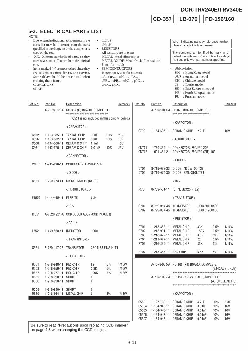
6-11
6-2. ELECTRICAL PARTS LIST
Ref. No. Part No. Description Remarks Ref. No. Part No. Description Remarks
NOTE:• Due to standardization, replacements in the
parts list may be different from the partsspecified in the diagrams or the componentsused on the set.
• -XX, -X mean standardized parts, so theymay have some difference from the originalone.
• Items marked “*” are not stocked since theyare seldom required for routine service.Some delay should be anticipated whenordering these items.
• CAPACITORS:uF: µF
• COILSuH: µH
• RESISTORSAll resistors are in ohms.METAL: metal-film resistorMETAL OXIDE: Metal Oxide-film resistorF: nonflammable
• SEMICONDUCTORSIn each case, u: µ, for example:uA...: µA... , uPA... , µPA... ,uPB... , µPB... , uPC... , µPC... ,uPD..., µPD...
The components identified by mark 0 ordotted line with mark 0 are critical for safety.Replace only with part number specified.
When indicating parts by reference number,please include the board name.
DCR-TRV240E/TRV340E
• AbbreviationHK : Hong Kong modelAUS : Australian modelCH : Chinese modelJE : Tourist modelEE : East European modelNE : North European modelRU : Russian model
CD-357 LB-076 PD-156/160
Be sure to read “Precautions upon replacing CCD imager”on page 4-8 when changing the CCD imager.
A-7078-051-A CD-357 (Q) BOARD, COMPLETE*************************
(IC551 is not included in this complte board.)
< CAPACITOR >
C552 1-113-985-11 TANTAL. CHIP 10uF 20% 20VC556 1-113-682-11 TANTAL. CHIP 33uF 20% 10VC560 1-164-360-11 CERAMIC CHIP 0.1uF 16VC561 1-162-970-11 CERAMIC CHIP 0.01uF 10% 25V
< CONNECTOR >
CN551 1-785-836-11 CONNECTOR, FFC/FPC 16P
< DIODE >
D551 8-719-073-01 DIODE MA111-(K8).S0
< FERRITE BEAD >
FB552 1-414-445-11 FERRITE 0uH
< IC >
IC551 A-7028-921-A CCD BLOCK ASSY (CCD IMAGER)
< COIL >
L552 1-469-528-91 INDUCTOR 100uH
< TRANSISTOR >
Q551 8-729-117-73 TRANSISTOR 2SC4178-F13F14-T1
< RESISTOR >
R551 1-218-940-11 RES-CHIP 82 5% 1/16WR553 1-218-959-11 RES-CHIP 3.3K 5% 1/16WR557 1-218-977-11 RES-CHIP 100K 5% 1/16WR565 1-218-990-11 SHORT 0R566 1-218-990-11 SHORT 0
R568 1-218-990-11 SHORT 0R569 1-216-864-11 METAL CHIP 0 5% 1/16W
************************************************************
A-7078-049-A LB-076 BOARD, COMPLETE**********************
< CAPACITOR >
C702 1-164-505-11 CERAMIC CHIP 2.2uF 16V
< CONNECTOR >
CN701 1-779-334-11 CONNECTOR, FFC/FPC 20PCN702 1-691-354-21 CONNECTOR, FFC/FPC (ZIF) 16P
< DIODE >
D701 8-719-082-33 DIODE NSCW100-T38D702 8-719-074-30 DIODE SML-310LTT86
< IC >
IC701 8-759-581-11 IC NJM2125F(TE2)
< TRANSISTOR >
Q701 8-759-054-48 TRANSISTOR UP04601008S0Q702 8-729-054-45 TRANSISTOR UP04312008S0
< RESISTOR >
R701 1-218-883-11 METAL CHIP 33K 0.5% 1/10WR702 1-218-901-11 METAL CHIP 180K 0.5% 1/10WR703 1-216-827-11 METAL CHIP 3.3K 5% 1/16WR704 1-211-977-11 METAL CHIP 22 0.5% 1/10WR706 1-216-839-11 METAL CHIP 33K 5% 1/16W
R707 1-218-867-11 RES-CHIP 6.8K 5% 1/10W************************************************************
A-7078-052-A PD-160 (X6) BOARD, COMPLETE(E,HK,AUS,CH,JE)
**************************************A-7078-096-A PD-156 (XC12) BOARD, COMPLETE
(AEP,UK,EE,NE,RU)**************************************
< CAPACITOR >
C5501 1-127-760-11 CERAMIC CHIP 4.7uF 10% 6.3VC5504 1-164-943-11 CERAMIC CHIP 0.01uF 10% 16VC5505 1-164-943-11 CERAMIC CHIP 0.01uF 10% 16VC5506 1-164-943-11 CERAMIC CHIP 0.01uF 10% 16VC5507 1-164-943-11 CERAMIC CHIP 0.01uF 10% 16V
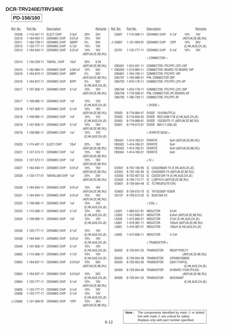
6-12
Ref. No. Part No. Description Remarks Ref. No. Part No. Description Remarks
DCR-TRV240E/TRV340E
Note : The components identified by mark 0 or dottedline with mark 0 are critical for safety.Replace only with part number specified.
C5509 1-110-457-11 ELECT CHIP 3.3uF 20% 25VC5510 1-164-943-11 CERAMIC CHIP 0.01uF 10% 16VC5511 1-164-739-11 CERAMIC CHIP 560PF 5% 50VC5512 1-125-777-11 CERAMIC CHIP 0.1uF 10% 10VC5513 1-164-943-11 CERAMIC CHIP 0.01uF 10% 16V
(AEP,UK,EE,NE,RU)
C5514 1-135-259-11 TANTAL. CHIP 10uF 20% 6.3V(AEP,UK,EE,NE,RU)
C5515 1-162-964-11 CERAMIC CHIP 0.001uF 10% 50VC5516 1-164-870-11 CERAMIC CHIP 68PF 5% 50V
(AEP,UK,EE,NE,RU)C5516 1-164-872-11 CERAMIC CHIP 82PF 5% 50V
(E,HK,AUS,CH,JE)C5517 1-107-826-11 CERAMIC CHIP 0.1uF 10% 16V
(AEP,UK,EE,NE,RU)
C5517 1-109-982-11 CERAMIC CHIP 1uF 10% 10V(E,HK,AUS,CH,JE)
C5518 1-107-826-11 CERAMIC CHIP 0.1uF 10% 16V(AEP,UK,EE,NE,RU)
C5518 1-109-982-11 CERAMIC CHIP 1uF 10% 10V(E,HK,AUS,CH,JE)
C5519 1-107-826-11 CERAMIC CHIP 0.1uF 10% 16V(AEP,UK,EE,NE,RU)
C5519 1-109-982-11 CERAMIC CHIP 1uF 10% 10V(E,HK,AUS,CH,JE)
C5520 1-115-407-11 ELECT CHIP 10uF 20% 16V(AEP,UK,EE,NE,RU)
C5521 1-127-573-11 CERAMIC CHIP 1uF 10% 16V(AEP,UK,EE,NE,RU)
C5524 1-127-573-11 CERAMIC CHIP 1uF 10% 16V(AEP,UK,EE,NE,RU)
C5527 1-164-943-11 CERAMIC CHIP 0.01uF 10% 16V(AEP,UK,EE,NE,RU)
C5528 1-135-177-21 TANTALUM CHIP 1uF 20% 20V(AEP,UK,EE,NE,RU)
C5530 1-164-943-11 CERAMIC CHIP 0.01uF 10% 16V(AEP,UK,EE,NE,RU)
C5531 1-164-943-11 CERAMIC CHIP 0.01uF 10% 16V(AEP,UK,EE,NE,RU)
C5532 1-109-982-11 CERAMIC CHIP 1uF 10% 10V(E,HK,AUS,CH,JE)
C5533 1-115-566-11 CERAMIC CHIP 4.7uF 10% 10V(E,HK,AUS,CH,JE)
C5534 1-109-982-11 CERAMIC CHIP 1uF 10% 10V(E,HK,AUS,CH,JE)
C5536 1-125-777-11 CERAMIC CHIP 0.1uF 10% 10V(E,HK,AUS,CH,JE)
C5538 1-164-943-11 CERAMIC CHIP 0.01uF 10% 16V(E,HK,AUS,CH,JE)
C5540 1-107-826-11 CERAMIC CHIP 0.1uF 10% 16V(E,HK,AUS,CH,JE)
C5602 1-115-566-11 CERAMIC CHIP 4.7uF 10% 10V(E,HK,AUS,CH,JE)
C5603 1-164-657-11 CERAMIC CHIP 0.015uF 10% 50V(AEP,UK,EE,NE,RU)
C5604 1-164-657-11 CERAMIC CHIP 0.015uF 10% 50V(E,HK,AUS,CH,JE)
C5604 1-125-777-11 CERAMIC CHIP 0.1uF 10% 10V(AEP,UK,EE,NE,RU)
C5605 1-125-777-11 CERAMIC CHIP 0.1uF 10% 10VC5606 1-125-777-11 CERAMIC CHIP 0.1uF 10% 10V
(E,HK,AUS,CH,JE)0C5606 1-131-959-91 CERAMIC CHIP 12PF 10% 3KV
(AEP,UK,EE,NE,RU)
C5607 1-115-566-11 CERAMIC CHIP 4.7uF 10% 10V(AEP,UK,EE,NE,RU)
0C5607 1-131-959-91 CERAMIC CHIP 12PF 10% 3KV(E,HK,AUS,CH,JE)
C5701 1-125-777-11 CERAMIC CHIP 0.1uF 10% 10V
< CONNECTOR >
CN5501 1-815-031-11 CONNECTOR, FFC/FPC (ZIF) 24P* CN5502 1-573-984-11 CONNECTOR, BOARD TO BOARD 10P
CN5601 1-764-709-11 CONNECTOR, FFC/FPC 10PCN5701 1-794-998-31 PIN, CONNECTOR 20PCN5702 1-816-176-11 CONNECTOR, FFC/FPC (ZIF) 6P
CN5703 1-816-178-11 CONNECTOR, FFC/FPC (ZIF) 20PCN5704 1-778-508-21 PIN, CONNECTOR (PC BOARD) 6PCN5705 1-766-759-11 CONNECTOR, FFC/FPC 4P
< DIODE >
D5502 8-719-084-47 DIODE 1SV290(TPL3)D5503 8-719-050-42 DIODE RD3.3UM-T1B (E,HK,AUS,CH,JE)D5503 8-719-988-61 DIODE 1SS355TE-17 (AEP,UK,EE,NE,RU)D5601 8-719-073-01 DIODE MA111-(K8).S0
< FERRITE BEAD >
FB5501 1-414-760-21 FERRITE 0uH (AEP,UK,EE,NE,RU)FB5502 1-414-760-21 FERRITE 0uHFB5503 1-414-760-21 FERRITE 0uH (AEP,UK,EE,NE,RU)FB5504 1-414-760-21 FERRITE 0uH
< IC >
IC5501 8-752-100-95 IC CXA3289AR-T4 (E,HK,AUS,CH,JE)IC5501 8-752-102-40 IC CXA3592R-T4 (AEP,UK,EE,NE,RU)IC5502 8-752-407-33 IC CXD3512R-T4 (E,HK,AUS,CH,JE)IC5502 8-759-714-77 IC LZ9FF474 (AEP,UK,EE,NE,RU)IC5601 8-759-564-49 IC TC7W53FU(TE12R)
IC5602 8-759-075-70 IC TA75S393F-TE85RIC5701 8-759-573-02 IC BU9735K-E2
< COIL >
L5501 1-469-527-91 INDUCTOR 47uHL5503 1-412-949-21 INDUCTOR 6.8uH (AEP,UK,EE,NE,RU)L5505 1-412-956-21 INDUCTOR 27uH (E,HK,AUS,CH,JE)L5601 1-419-387-11 INDUCTOR 100uH (AEP,UK,EE,NE,RU)L5601 1-419-387-21 INDUCTOR 100uH (E,HK,AUS,CH,JE)
L5602 1-412-056-11 INDUCTOR 4.7uH
< TRANSISTOR >
Q5502 8-729-041-23 TRANSISTOR MGSF1P02LT1(AEP,UK,EE,NE,RU)
Q5503 8-759-054-48 TRANSISTOR UP04601008S0Q5504 8-729-052-65 TRANSISTOR 2SA1774HT2L
(E,HK,AUS,CH,JE)Q5504 8-729-054-48 TRANSISTOR N1B04FE-Y/GR(TPLR3)
(AEP,UK,EE,NE,RU)Q5505 8-729-041-23 TRANSISTOR NDS356AP
(E,HK,AUS,CH,JE)
PD-156/160
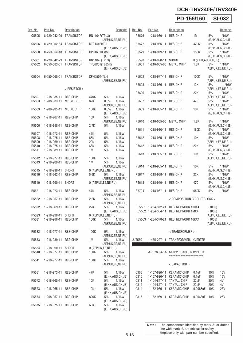
6-13
Ref. No. Part No. Description Remarks Ref. No. Part No. Description Remarks
DCR-TRV240E/TRV340E
Q5505 8-729-042-29 TRANSISTOR RN1104F(TPL3)(AEP,UK,EE,NE,RU)
Q5506 8-729-052-64 TRANSISTOR DTC144EHT2L(E,HK,AUS,CH,JE)
Q5508 8-759-054-48 TRANSISTOR UP04601008S0(E,HK,AUS,CH,JE)
Q5601 8-729-042-29 TRANSISTOR RN1104F(TPL3)Q5602 6-550-083-01 TRANSISTOR TPC6C01(TE85R)
(E,HK,AUS,CH,JE)
Q5604 6-550-065-01 TRANSISTOR CPH5504-TL-E(AEP,UK,EE,NE,RU)
< RESISTOR >
R5501 1-218-985-11 RES-CHIP 470K 5% 1/16WR5503 1-208-933-11 METAL CHIP 82K 0.5% 1/16W
(AEP,UK,EE,NE,RU)R5503 1-208-935-11 METAL CHIP 100K 0.5% 1/16W
(E,HK,AUS,CH,JE)R5505 1-218-967-11 RES-CHIP 15K 5% 1/16W
(AEP,UK,EE,NE,RU)R5506 1-218-958-11 RES-CHIP 2.7K 5% 1/16W
R5507 1-218-973-11 RES-CHIP 47K 5% 1/16WR5508 1-218-975-11 RES-CHIP 68K 5% 1/16WR5509 1-218-969-11 RES-CHIP 22K 5% 1/16WR5510 1-218-975-11 RES-CHIP 68K 5% 1/16WR5511 1-218-989-11 RES-CHIP 1M 5% 1/16W
R5512 1-218-977-11 RES-CHIP 100K 5% 1/16WR5513 1-218-989-11 RES-CHIP 1M 5% 1/16W
(AEP,UK,EE,NE,RU)R5515 1-218-990-11 SHORT 0 (AEP,UK,EE,NE,RU)R5516 1-218-962-11 RES-CHIP 5.6K 5% 1/16W
(AEP,UK,EE,NE,RU)R5519 1-218-990-11 SHORT 0 (AEP,UK,EE,NE,RU)
R5521 1-218-973-11 RES-CHIP 47K 5% 1/16W(AEP,UK,EE,NE,RU)
R5522 1-218-957-11 RES-CHIP 2.2K 5% 1/16W(AEP,UK,EE,NE,RU)
R5522 1-218-969-11 RES-CHIP 22K 5% 1/16W(E,HK,AUS,CH,JE)
R5523 1-218-990-11 SHORT 0 (AEP,UK,EE,NE,RU)R5531 1-218-980-11 RES-CHIP 180K 5% 1/16W
(AEP,UK,EE,NE,RU)
R5532 1-218-977-11 RES-CHIP 100K 5% 1/16W(AEP,UK,EE,NE,RU)
R5533 1-218-989-11 RES-CHIP 1M 5% 1/16W(AEP,UK,EE,NE,RU)
R5534 1-218-990-11 SHORT 0 (AEP,UK,EE,NE,RU)R5540 1-218-977-11 RES-CHIP 100K 5% 1/16W
(AEP,UK,EE,NE,RU)R5541 1-218-977-11 RES-CHIP 100K 5% 1/16W
(AEP,UK,EE,NE,RU)
R5551 1-218-973-11 RES-CHIP 47K 5% 1/16W(E,HK,AUS,CH,JE)
R5572 1-218-965-11 RES-CHIP 10K 5% 1/16W(E,HK,AUS,CH,JE)
R5573 1-218-965-11 RES-CHIP 10K 5% 1/16W(E,HK,AUS,CH,JE)
R5574 1-208-957-11 RES-CHIP 820K 5% 1/16W(E,HK,AUS,CH,JE)
R5575 1-218-975-11 RES-CHIP 68K 5% 1/16W(E,HK,AUS,CH,JE)
R5576 1-218-989-11 RES-CHIP 1M 5% 1/16W(E,HK,AUS,CH,JE)
R5577 1-218-985-11 RES-CHIP 470K 5% 1/16W(E,HK,AUS,CH,JE)
R5579 1-218-979-11 RES-CHIP 150K 5% 1/16W(E,HK,AUS,CH,JE)
R5590 1-218-990-11 SHORT 0 (E,HK,AUS,CH,JE)R5601 1-216-055-00 METAL CHIP 1.8K 5% 1/10W
(AEP,UK,EE,NE,RU)
R5602 1-218-977-11 RES-CHIP 100K 5% 1/16W(AEP,UK,EE,NE,RU)
R5603 1-218-966-11 RES-CHIP 12K 5% 1/16W(AEP,UK,EE,NE,RU)
R5606 1-218-969-11 RES-CHIP 22K 5% 1/16W(AEP,UK,EE,NE,RU)
R5607 1-218-949-11 RES-CHIP 470 5% 1/16W(AEP,UK,EE,NE,RU)
R5609 1-218-965-11 RES-CHIP 10K 5% 1/16W(E,HK,AUS,CH,JE)
R5610 1-216-055-00 METAL CHIP 1.8K 5% 1/10W(E,HK,AUS,CH,JE)
R5611 1-218-980-11 RES-CHIP 180K 5% 1/16W(E,HK,AUS,CH,JE)
R5612 1-218-965-11 RES-CHIP 10K 5% 1/16W(AEP,UK,EE,NE,RU)
R5612 1-218-969-11 RES-CHIP 22K 5% 1/16W(E,HK,AUS,CH,JE)
R5613 1-218-965-11 RES-CHIP 10K 5% 1/16W(AEP,UK,EE,NE,RU)
R5614 1-218-965-11 RES-CHIP 10K 5% 1/16W(E,HK,AUS,CH,JE)
R5617 1-218-969-11 RES-CHIP 22K 5% 1/16W(E,HK,AUS,CH,JE)
R5618 1-218-949-11 RES-CHIP 470 5% 1/16W(E,HK,AUS,CH,JE)
R5704 1-218-987-11 RES-CHIP 680K 5% 1/16W
< COMPOSITION CIRCUIT BLOCK >
RB5501 1-234-372-21 RES, NETWORK 100X4 (1005)RB5502 1-234-384-11 RES, NETWORK 1MX4 (1005)
(AEP,UK,EE,NE,RU)RB5503 1-234-378-21 RES, NETWORK 10KX4 (1005)
(AEP,UK,EE,NE,RU)
< TRANSFORMER >
0T5601 1-435-227-11 TRANSFORMER, INVERTER************************************************************
A-7078-047-A SI-032 BOARD, COMPLETE*********************
< CAPACITOR >
C305 1-107-826-11 CERAMIC CHIP 0.1uF 10% 16VC310 1-107-826-11 CERAMIC CHIP 0.1uF 10% 16VC311 1-104-847-11 TANTAL. CHIP 22uF 20% 4VC312 1-104-847-11 TANTAL. CHIP 22uF 20% 4VC314 1-162-969-11 CERAMIC CHIP 0.0068uF 10% 25V
C315 1-162-969-11 CERAMIC CHIP 0.0068uF 10% 25V
SI-032PD-156/160
Note : The components identified by mark 0 or dottedline with mark 0 are critical for safety.Replace only with part number specified.
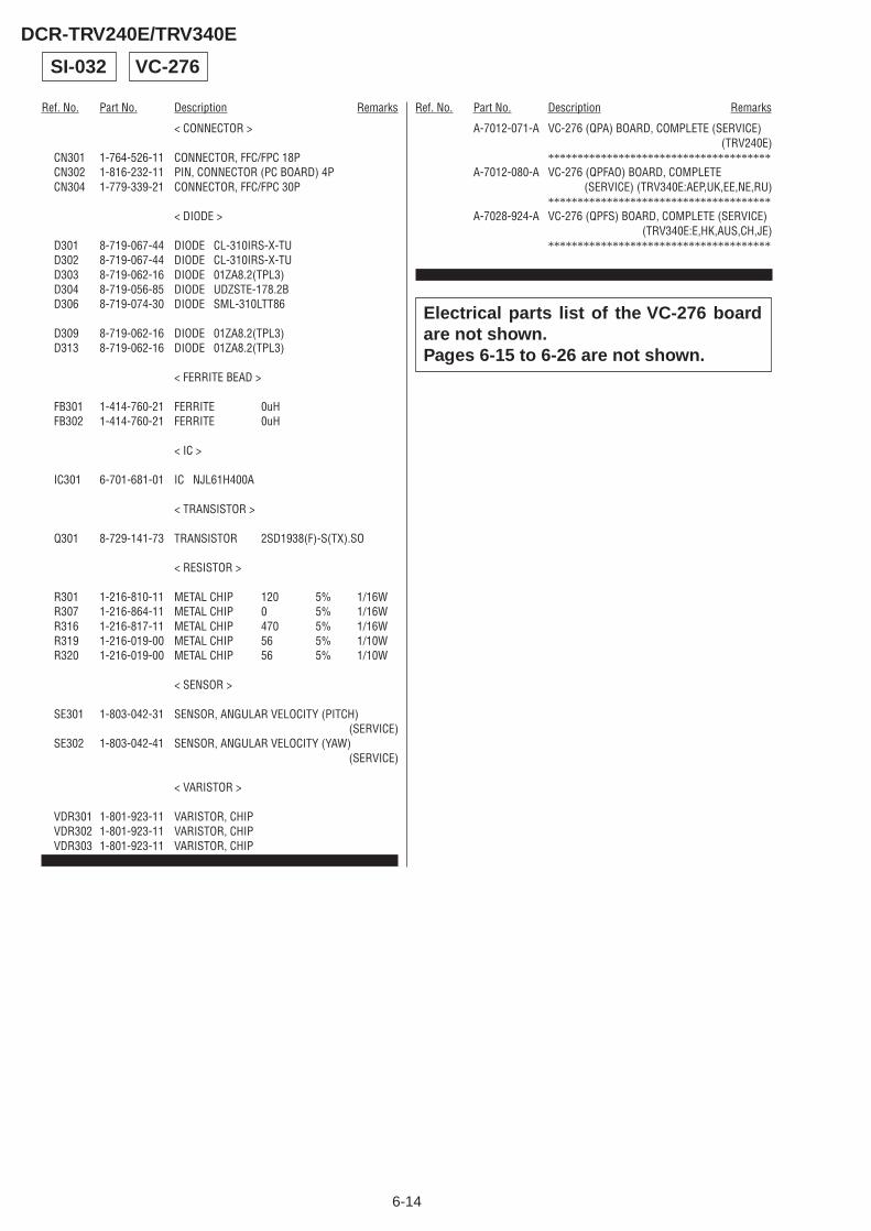
6-14
Ref. No. Part No. Description Remarks Ref. No. Part No. Description Remarks
DCR-TRV240E/TRV340E
< CONNECTOR >
CN301 1-764-526-11 CONNECTOR, FFC/FPC 18PCN302 1-816-232-11 PIN, CONNECTOR (PC BOARD) 4PCN304 1-779-339-21 CONNECTOR, FFC/FPC 30P
< DIODE >
D301 8-719-067-44 DIODE CL-310IRS-X-TUD302 8-719-067-44 DIODE CL-310IRS-X-TUD303 8-719-062-16 DIODE 01ZA8.2(TPL3)D304 8-719-056-85 DIODE UDZSTE-178.2BD306 8-719-074-30 DIODE SML-310LTT86
D309 8-719-062-16 DIODE 01ZA8.2(TPL3)D313 8-719-062-16 DIODE 01ZA8.2(TPL3)
< FERRITE BEAD >
FB301 1-414-760-21 FERRITE 0uHFB302 1-414-760-21 FERRITE 0uH
< IC >
IC301 6-701-681-01 IC NJL61H400A
< TRANSISTOR >
Q301 8-729-141-73 TRANSISTOR 2SD1938(F)-S(TX).SO
< RESISTOR >
R301 1-216-810-11 METAL CHIP 120 5% 1/16WR307 1-216-864-11 METAL CHIP 0 5% 1/16WR316 1-216-817-11 METAL CHIP 470 5% 1/16WR319 1-216-019-00 METAL CHIP 56 5% 1/10WR320 1-216-019-00 METAL CHIP 56 5% 1/10W
< SENSOR >
SE301 1-803-042-31 SENSOR, ANGULAR VELOCITY (PITCH)(SERVICE)
SE302 1-803-042-41 SENSOR, ANGULAR VELOCITY (YAW)(SERVICE)
< VARISTOR >
VDR301 1-801-923-11 VARISTOR, CHIPVDR302 1-801-923-11 VARISTOR, CHIPVDR303 1-801-923-11 VARISTOR, CHIP
************************************************************
SI-032 VC-276
Electrical parts list of the VC-276 boardare not shown.Pages 6-15 to 6-26 are not shown.
A-7012-071-A VC-276 (QPA) BOARD, COMPLETE (SERVICE)(TRV240E)
**************************************A-7012-080-A VC-276 (QPFAO) BOARD, COMPLETE
(SERVICE) (TRV340E:AEP,UK,EE,NE,RU)**************************************
A-7028-924-A VC-276 (QPFS) BOARD, COMPLETE (SERVICE)(TRV340E:E,HK,AUS,CH,JE)
**************************************
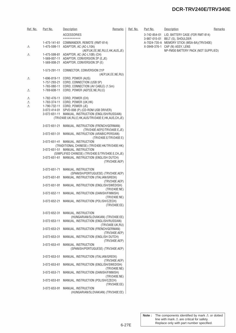
6-27E
Ref. No. Part No. Description Remarks Ref. No. Part No. Description Remarks
DCR-TRV240E/TRV340E
Note : The components identified by mark 0 or dottedline with mark 0 are critical for safety.Replace only with part number specified.
ACCESSORIES***********
1-475-141-61 COMMANDER, REMOTE (RMT-814)0 1-475-599-11 ADAPTOR, AC (AC-L10A)
(AEP,UK,EE,NE,RU,E,HK,AUS,JE)0 1-475-599-81 ADAPTOR, AC (AC-L10B) (CH)
1-569-007-11 ADAPTOR, CONVERSION 2P (E,JE)1-569-008-21 ADAPTOR, CONVERSION 2P (E)
1-573-291-11 CONNECTOR, CONVERSION 21P(AEP,UK,EE,NE,RU)
0 1-696-819-11 CORD, POWER (AUS)1-757-293-21 CORD, CONNECTION (USB 5P)1-765-080-11 CORD, CONNECTION (AV CABLE) (1.5m)
0 1-769-608-11 CORD, POWER (AEP,EE,NE,RU,E)
0 1-782-476-11 CORD, POWER (CH)0 1-783-374-11 CORD, POWER (UK,HK)0 1-790-732-11 CORD, POWER (JE)
3-072-414-01 SPVD-008 (P) (CD-ROM USB DRIVER)3-072-651-11 MANUAL, INSTRUCTION (ENGLISH/RUSSIAN)
(TRV240E:UK,RU,E,HK,AUS/TRV340E:E,HK,AUS,CH,JE)
3-072-651-21 MANUAL, INSTRUCTION (FRENCH/GERMAN)(TRV240E:AEP,E/TRV340E:E,JE)
3-072-651-31 MANUAL, INSTRUCTION (ARABIC/PERSIAN)(TRV240E:E/TRV340E:E)
3-072-651-41 MANUAL, INSTRUCTION(TRADITIONAL CHINESE) (TRV240E:HK/TRV340E:HK)
3-072-651-51 MANUAL, INSTRUCTION(SIMPLIFIED CHINESE) (TRV240E:E/TRV340E:E,CH,JE)
3-072-651-61 MANUAL, INSTRUCTION (ENGLISH DUTCH)(TRV240E:AEP)
3-072-651-71 MANUAL, INSTRUCTION(SPANISH/PORTUGUESE) (TRV240E:AEP)
3-072-651-81 MANUAL, INSTRUCTION (ITALIAN/GREEK)(TRV240E:AEP)
3-072-651-91 MANUAL, INSTRUCTION (ENGLISH/SWEDISH)(TRV240E:NE)
3-072-652-11 MANUAL, INSTRUCTION (DANISH/FINNISH)(TRV240E:NE)
3-072-652-21 MANUAL, INSTRUCTION (POLISH/CZECH)(TRV240E:EE)
3-072-652-31 MANUAL, INSTRUCTION(HUNGARIAN/SLOVAKIAN) (TRV240E:EE)
3-072-653-11 MANUAL, INSTRUCTION (ENGLISH/RUSSIAN)(TRV340E:UK,RU)
3-072-653-21 MANUAL, INSTRUCTION (FRENCH/GERMAN)(TRV340E:AEP)
3-072-653-31 MANUAL, INSTRUCTION (ENGLISH DUTCH)(TRV340E:AEP)
3-072-653-41 MANUAL, INSTRUCTION(SPANISH/PORTUGUESE) (TRV340E:AEP)
3-072-653-51 MANUAL, INSTRUCTION (ITALIAN/GREEK)(TRV340E:AEP)
3-072-653-61 MANUAL, INSTRUCTION (ENGLISH/SWEDISH)(TRV340E:NE)
3-072-653-71 MANUAL, INSTRUCTION (DANISH/FINNISH)(TRV340E:NE)
3-072-653-81 MANUAL, INSTRUCTION (POLISH/CZECH)(TRV340E:EE)
3-072-653-91 MANUAL, INSTRUCTION(HUNGARIAN/SLOVAKIAN) (TRV340E:EE)
3-742-854-01 LID, BATTERY CASE (FOR RMT-814)3-987-015-01 BELT (S), SHOULDERA-7024-735-A MEMORY STICK (MSA-8A)(TRV340E)X-3949-376-1 CAP (N) ASSY, LENS
NP-FM30 BATTERY PACK (NOT SUPPLIED)
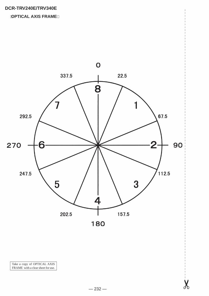
Take a copy of OPTICAL AXISFRAME with a clear sheet for use.
— 232 —
⟨OPTICAL AXIS FRAME⟩
DCR-TRV240E/TRV340E
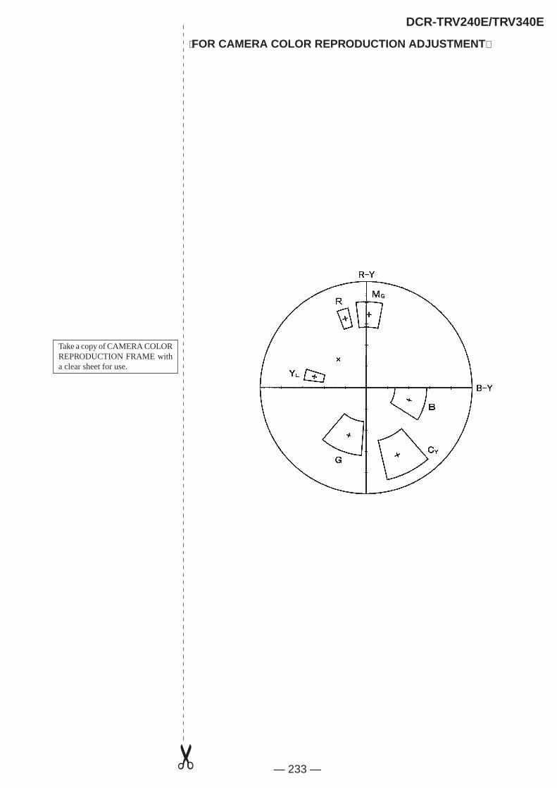
Take a copy of CAMERA COLORREPRODUCTION FRAME witha clear sheet for use.
— 233 —
⟨FOR CAMERA COLOR REPRODUCTION ADJUSTMENT⟩
DCR-TRV240E/TRV340E

DCR-TRV240E/TRV340E
— 234 —Sony EMCS Co. 2002I1600-1
©2002.9Published by DI Customer Center
9-929-931-32

SERVICE MANUAL
SUPPLEMENT-1File this supplement-1 with Service Manual.
DCR-TRV240E/TRV340ERMT-814
AEP ModelUK Model
E ModelHong Kong ModelAustralian Model
East European ModelNorth European Model
Russian ModelDCR-TRV240E/TRV340E
Chinese ModelTourist Model
DCR-TRV340E
Level 2
Ver 1.3 2002. 09
• This supplement-1 is issued for DCR-TRV240E (AEP, UK, East European, NorthEuropean, Russian)/TRV340E (AEP, UK, East European, North European, Russian)model only.
• This supplement-1 has no relation with other models.
Subject• The LCD assembly Type SO (123k) is added to the conventional Type SO (61k).
In accordance with the addition of Type SO (123k), Schematic diagram, adjustmentand repair parts list of the PD-160 board are changed.
• To check the LCD Type, refer to “LCD Type Check of SECTION 5. 1-5 LCD SYSTEMADJUSTMENT”.
• There are combinations of the LCD assembly and the PD-160 board, use them inthe combination as shown below.
LCD Panel
PD-160 Board
Fluorescent ColdCathode Tube
LCD Type SO (61k)
ACX308AK-18-753-050-65
PD-160 (X6) BOARD, COMPLETEA-7078-052-A
1-518-796-11
LCD Type SO (123k)
INDICATOR MODULE LIQUID CRYST8-753-050-80
PD-160 (X12) BOARD, COMPLETEA-7078-372-A
1-518-798-22

DCR-TRV240E/TRV340E
For Schematic Diagram• Refer to page 4-23 for printed wiring board.• Refer to page 4-92 for waveforms.
0.4
1.7
2.8
2.8
1.8 2.8
1.8
2.8
0
0
0
2.8
1.5
1.5
1.5
1.5
1.5
1.5
1.5
2.0
3.0
3.0
3.0
3.0
0.7
2.9 0
1.5
1.5
1.5
1.5
1.5
1.5
1.5
1.5
1.5
1.5
1.5
1.5
1.5
1.5
10
NO MARK:REC/PB MODE
R5620XX
R5619XX
R5616XX
470R5618
1/10W1800
R5610
R5611180k
L5601100uH
MA111-(K8).S0D5601
12pC5607
0.015uB
C5604
0.1uB
C5606
LED
IC5601TC7W53FU(TE12R)
1 COM
2 INH
3 VEE
4 GND 5A
6CH1
7CH0
8VCC
B
C56050.1u
DETIN
R561222k
XXR5613
10PCN5601
1 LED_GND
2 LED
3 BL_LOW
4 N.C.
5 N.C.
6 N.C.
7 N.C.
8 N.C.
9 N.C.
10 BL_HIGH
22kR5617
IC5602TA75S393F-TE85R
12
345
D5603XX
LND705
CH_GND
D5604XX
12
T5601
1
2
3
4
5
6
10
DAC
BL_ON
10kR5614
Q5603XX
3
3
5
4
6
2
1
4.7uB
C5602
XXC5608
D5602XX
XXR5621
DTC144EHT2LQ5601
10kR5609
XXD5605
XXQ5604
1
5
4
2
3
TPC6C01(TE85R)Q5602
6
1
5
4
3
2
4.7uHL5602
0.1uB
C5701
6PCN5704
1
2
3
4
5
6
CN5702 6P
1
2
3
4
5
6
CN5705 4P
1
2
3
4
XVD
20PCN5701
1
2
3
4
5
6
7
8
9
10
11
12
13
14
15
16
17
18
19
20
XVC_SO
XSYS_RST
XXR5702
680kR5704
PANEL_13.3V
CN5703 20P
1
2
3
4
5
6
7
8
9
10
11
12
13
14
15
16
17
18
19
20
XCS_PANEL
REG_GND
PANEL_R
BU9735K-E2IC5701
1 OSC1
2 OSC2
3 VSS
4 VC
5 VLCD
6 VDD
7 SCK
8 SD
9
XC
S
10
C/X
D
11
CO
M1
12
CO
M2
13
CO
M3
14
CO
M4
15
SEG
1
16
SEG
2
17SEG3
18SEG4
19SEG5
20SEG6
21SEG7
22SEG8
23SEG9
24SEG10
25
SEG
11
26
SEG
12
27
SEG
13
28
SEG
14
29
SEG
15
30
SEG
16
31
SEG
17
32
SEG
18
PANEL_B
SYNC
PANEL_G
XVC_SCK
1
A
S601
LND007
SE_GND
PANEL_2.8V
SEG13
SEG2
COM4
SEG10
SEG11
SEG5
SEG3
SEG
1
SEG8
SEG6
XCS
SEG9
SEG5
SEG8
XCS
SEG
13
SO
SCK
C/XD
SEG
16
SO
SEG7
CO
M3
SEG3
SEG15
CO
M1
SEG4
SEG
2
SEG12
COM3
SEG
12
SEG
11
SEG9
SEG
15
SEG1
COM2
SEG16
SEG
14
SEG7
CO
M4
SEG6
SCK
C/XD
SEG10
CO
M2
COM1
SEG14
SEG4
VCC
SL
FP-414 FLEXIBLE is replaced as a block.
By measuring the resistor value between Pin6 of CN5502and GND the type of LCD can be discriminated.
22k : LCD Type SO (61k)33k : LCD Type SO (123k)
LCD TYPE SO (61k) : DCR- TRV240E : E, AUS, HK/TRV340E : E, AUS, HK, CH, JE MODEL
LCD TYPE SO (123k) : DCR- TRV240E : AEP, UK, EE, NE, RU/TRV340E : AEP, UK, EE, NE, RU MODEL
AbbrebiationHK : Hong Kong modelAUS : Australian modelCH : Chinese modelJE : Tourist modelEE : East European modelNE : North European modelRU : Russian model
So that this PRINTED WIRING BOARD is omitted.
BACK LIGHTND901
INVERTERTRANSFORMER
SWITCH
IC5602
BACK LIGHTBRIGHT SWITCH
OSC
IC5601
CURRENT DETECT
2 TO(2/2)
PANEL_2.8V
XSYS_RST
GND
SEG2
SEG12
SEG15
PANEL_HOLD
REG_GND
BL_GND
COM1
PANEL_XVD
XPANEL_REV
XOSD_SCK
PANEL_13.3V
PANEL_4.75V
DISP_BL
SEG7
SEG16
PANEL_REV
N.C.
SEG10
BL_VDD
SEG9
N.C.
SEG13
PANEL_REV
GND
BL_GND
SEG11
OSD_SO
COM4
SEG14
BL_GND
VC_SO
PANEL_-15.3V
BL_REG
LCD_COM/XDATA
SEG5
SEG8
COM2
XCS_LCD_DA
XVC_SCK
PANEL_R
XCS_LCD_DRIVER
SEG3
BL_CONT
BL_VDD
COM3
DISP_LCD_VDD
SEG1
PANEL_G
C-SYNC/XHD
PANEL_B
SEG6
SE_GND
SEG4
J
CHA.DISPLAY DRIVE,BACK LIGHT(LCD/BL BLOCK)
108
B
PD-160 BOARD(1/2) (LCD TYPE SO)
D
52 4 12
E
113
16
G
I
1396 7
F
C
H
1 TO(2/2)
CHARACTORDISPLAY DRIVER
IC5701
D902
FLEXIBLE
LCD902CHARACTER DISPLAY UNIT
FP-414
BACKLIGHT
(PANEL REVERSE)
FLEXIBLEFP-412
THROUGH THEVP-076 HARNESS
TOVC-276 BOARD(24/25)CN1106
(PAGE 4-84)
THROUGH THECP-076 HARNESS
TOCONTROLSWITCH BLOCK(CF-2500)CN005
(PAGE 4-31)
VIDEO SIGNAL
REC
Y
PB
Y/CHROMA
SIGNAL PATH
CHROMA
XX MARK:NO MOUNT
— 3 — — 4 —
( ) : Page No. shown in ( ) indicates the page to refer on the original Service Manual.(Page 4-27)
Note : The components identified by mark 0 or dottedline with mark 0 are critical for safety.Replace only with part number specified.

DCR-TRV240E/TRV340E
— 5 — — 6 —
For Schematic Diagram• Refer to page 4-23 for printed wiring board.• Refer to page 4-92 for waveforms. ( ) : Page No. shown in ( ) indicates the page to refer on the original Service Manual.(Page 4-29)
1.2
2.8
2.5
2.0
2.7
2.8
2.8
1.4
2.8
1.8
1.8
1.8
0.7
1.8
2.7
0 2.8
1.4
1.4
2.8
7.1
1.7
13.4
7.1
1.7
7.1
1.7
7.1
1.7
13.4
2.8
0.5
0.5
2.8
0.5
1.4
1.4
1.4
1.4
2.4
6.8
6
5
4
1
2
3
13.4 13.4
0
0
2.8
7.6 13.4
7.0 7.6
7.0
7.0
6.4
7.0
6.4
13.4
2.7
2.8
0
1.4
1.4
2.5
2.8
2.7
2.2
2.0
0
2.7
0 0.5
0.5
2.8
0.5
2.8
1.4
2.8
1.4
1.4
2.8
0
1.4
2.5
0
0.2
2.8
0
1.4
1.4
0
2.8
2.6
0.3
2.8
2.9 0
8
9
7
NO MARK:REC/PB MODE
1.6
1.0
0.01uC5505
1SV290(TPL3)D5502
22kR5509
PANEL_G
XXR5505
C5509
25V3.3u
100kR5512
47kR5507
PANEL_13.3V
*L5505
XVD
0.01uB
C5510
R5504XX
20121u BC5519
0.01uB
C5504
IC5501CXA3289BR-T4
1
XS
H.S
AV
E
2
SH
_R
3
SH
_G
4
SH
_B
5
SH
_A
6
GN
D/N
.C.
7
BIA
S
8
OP
_IN
+
9
OP
_IN
-
10
OP
_OU
T
11V
CO
12
CO
M_D
C
13COM_IN
14COM_OUT
15Vcc3
16VREF
17GND1
18GND2/N.C.
21G_DC_DET
19R_DC_DET
20VR
22VG
23B_DC_DET
24VB
25
Vcc
2
26
P_D
C_D
ET
27
VP
28
XV
P.S
AV
E
29
PFR
P
30
FRP
31
PR
G
32
BLA
CK
_IN
33
BG
P
34
N.C
.
35
EXT_
DA
36
N.C
./R
_IN
JEC
T
37 N.C./C_BG
38 XC.SAVE39 XSCK
40 SI
41 XCS
42 Vcc1
45 XP.SAVE
44 LPF_ADJ
43 TRAP_ADJ
46 B_IN
47 G_IN
48 R_IN
L550147uH
XXC5508
XCS_PANEL
XXC5503
20121u BC5518
XVC_SCK
XVC_SO
LED
*R5503
68kR5510
0.001uB
C5515
DETIN
REG_GND
PANEL_R
470kR5501
PANEL_2.8V
68kR5508
2700
R55
06
*C5516
20121u BC5517
1MR5511
0.01uC5506
560p
C55
11
SYNC
0.1uB
C5512
PANEL_B
DAC
0.01uC5507
CXD3512R-T4IC5502
1
HD
2
HD
O
3
XW
RT
4
BL_
ON
5
DET
IN
6
GN
D
7
TST0
8
LED
9
PW
M
10
TES
T
11
TES
T
12
TES
T
13TSTEN
14POFF
15RGT
16HCK1
17HCK2
18HST
21DWN
19VDD
20WIDE
22EN
23VCK
24VST
25
XS
TBY
26
OS
CO
27
OS
CI
28
XC
.SA
VE
29
RP
D
30
TES
T
31
VS
S
32
SH
A
33
SH
B
34
SH
G
35
SH
R
36
XC
LR
37 XCLP
38 PRG
39 SBLK
40 FRP
41 PFRP
42 XSCK
45 SO
44 XCS
43 VDD
46 SI
47 VDO
48 XVD
R555147k
10PCN5502
1 VB
2 XVD_OUT
3 VG
4 PSIG
5 VR
6 MAKER_CHECK
7 XHD
8 XHD_OUT
9 GND
10 GND*
R5522
XXC5527
C5529XX
R5560XX
XXQ5501
FB55020uH
L5504XX
20121u BC5532
3216
4.7uB
C5533
RD3.3UM-T1BD5503
2012
1uB
C5534
10kR5572
10kR5573
2SA1774HT2LQ5504
820kR5574
68kR5575
1MR5576
0.1uB
C5536
MGSF1PO2LTQ5505
DTC144EHT2LQ5506
470kR5577
R5579150k
0.1uB
C5540
1608
24PCN5501
1 TEST2
2 RGT
3 B
4 R
5 G
6 PSIG
7 HCK1
8 HCK2
9 CRext
10 SOUT
11 REF
12 HST
13 WIDE
14 CS
15 VVSSG
16 VDOG
17 VSS
18 VDD
19 DWN
20 EN
21 VCK
22 VST
23 COM
24 TEST1
UP04601008S0Q5503
3
5
4 6
2
1
UP04601008S0Q5508
3
5
46
2
1
R5588XX
BL_ON
XSYS_RST
0R5590
FB55040uH
RB5501
RB5502
4.7uB
C5501
D5504XX
XXR5591
0.01uB
C5538
1
A
XCS_PANEL VR
VB
VGXVC_SCK
PFR
P
FRP
BG
P
XP.SAVE
BGP
XVC_SCK
XCS_PANEL
XVC_SO
XVD
SYNC
XVC_SO
XCS_PANEL
XVD
FRP
BLK
XP.
SA
VE
XC.SAVE
XTG_SO
PFRP
XHD_OUT
SYNC
XTG_SO
BLK
XVC_SCK
XC
.SA
VE
PR
G
PRG
VP
SH
4
SH
3
SH
2
SH
1
SH
2
SH
3
SH
4
SH
1
VB
VP
TG24
TG23
TG22
TG21
TG20
TG18
TG16
TG15
TG14
TG24
TG23
TG22
TG21
TG20
TG18
TG17
TG16
TG15V
RVG
TG14
TG17
VB
VG
VR
XH
D_O
UT
XV
D_O
UT
SYNC
SY
NC
XVD_OUT
DRIVER
Timing Generator
1608
2520
100X4
100KX4
SWITCH
SWITCH
LEVEL SHIFT
LCD B+ REG
LCD SWITCH
16
2
E
L
B
J
I
G
4 156
D
7 1312
H
9 14
F
10 113 8
C
5
K
2.5INCHLCD901
CPC (FOR CHECK)
IC5501
IC5502
1 TO(1/2)
2 TO(1/2)
PD-160 BOARD(2/2) (LCD TYPE SO)LCD DRIVE,TG(RGB/TG BLOCK)
SIGNAL PATH
REC
PB
VIDEO SIGNAL
Y/CHROMAYCHROMA
M
XX MARK:NO MOUNT
By measuring the resistor value between Pin6 of CN5502and GND the type of LCD can be discriminated.
22k : LCD Type SO (61k)33k : LCD Type SO (123k)
LCD TYPE SO (61k) : DCR- TRV240E : E, AUS, HK/TRV340E : E, AUS, HK, CH, JE MODEL
LCD TYPE SO (123k) : DCR- TRV240E : AEP, UK, EE, NE, RU/TRV340E : AEP, UK, EE, NE, RU MODEL
AbbrebiationHK : Hong Kong modelAUS : Australian modelCH : Chinese modelJE : Tourist modelEE : East European modelNE : North European modelRU : Russian model
*C5516, L5505, R552282P 27uH 22k : LCD TYPE SO (61k)68P 6.8uH 33k : LCD TYPE SO (123k)
*R5503100k : LCD TYPE SO (61k)82k : LCD TYPE SO (123k)

— 7 —
DCR-TRV240E/TRV340E
SECTION 5. ADJUSTMENTSPage
5-3
5-13
Before change After change
: Added portion. : Changed portion.
1. Adjusting items when replacingmain parts and boards
*5: LCD TYPE SO (PD-160 board)DCR-TRV240E: E, AUS, HKDCR-TRV340E: E, AUS, HK, CH, JE
1. Adjusting items when replacingmain parts and boards
*5: LCD TYPE SO (PD-160 board)DCR-TRV240E: E, AUS, HKDCR-TRV340E: E, AUS, HK, CH, JEDCR-TRV240E: AEP, UK, EE, NE, RUDCR-TRV340E: AEP, UK, EE, NE, RU
1-2. INITIALIZATION OF 8, A, B, C, D, E, F,1B, 1C, 1F PAGE DATA
3. C Page Table
5B to 5E
5F
60
61
62
63
64
65
66
67
68
69
6A
6B
6C
6D
6E
6F to 71
67/5C/67/68*1
53/70/53/59*1
8B/21/8B/22*1
29/9D/29/A1*1
00/08/00/08*1
99/3D/99/3F*1
84/7E/84/81*1
5F/6C/5F/6F*1
40/20/40/1E*1
00/37/00/37*1
Fixed data-1
Fixed data-2
VCO adj. (LCD)
V-COM adj. (LCD)
RGB AMP adj. (LCD)
Black limit adj. (LCD)*2Fixed data *3
PSIG gray adj. (LCD) *2COM AMP adj. (LCD) *3
White balance adj. (LCD)
Contrast adj. (LCD)
Center level adj. (LCD) *2Fixed data *3
Fixed data-2
Fixed data-1
Fixed data-2
Fixed data-1
Address RemarkInitial value
*1: A/B/C/DA: 2.5 LCD TYPE SH
DCR-TRV240E: AEP, UK, EE, NE, RUB: 2.5 LCD TYPE SO
DCR-TRV240E: E, AUS, HKC: 3.5 LCD TYPE SH
DCR-TRV340E: AEP, UK, EE, NE, RUD: 3.5 LCD TYPE SO
DCR-TRV340E: E, AUS, HK, CH, JE
1-2. INITIALIZATION OF 8, A, B, C, D, E, F,1B, 1C, 1F PAGE DATA
3. C Page Table
• AbbreviationHK : Hong Kong modelAUS : Australian modelCH : Chinese modelJE : Tourist modelEE : East European modelNE : North European modelRU : Russian model
5B to 5E
5F
60
61
62
63
64
65
66
67
68
69
6A
6B
6C
6D
6E
6F to 71
77/73/73/73*1
A7/8F/8F/8D*1
67/5C/68/70*1
53/70/59/5F*1
8B/21/22/1F*1
29/9D/A1/9C*1
00/08/08/07*1
99/3D/3F/40*1
84/7E/81/82*1
5F/6C/6F/6B*1
40/20/1E/13*1
00/37/37/35*1
32/0C/0C/2F*1
12/0C/0C/0F*1
1F/5F/5F/1F*1
Fixed data-1
Fixed data
Fixed data
VCO adj. (LCD)
V-COM adj. (LCD)
RGB AMP adj. (LCD)
Black limit adj. (LCD) *2
Fixed data *3
PSIG gray adj. (LCD) *2
COM AMP adj. (LCD) *3
White balance adj. (LCD)
Contrast adj. (LCD)
Center level adj. (LCD) *2
Fixed data *3
Fixed data
Fixed data
Fixed data-1
Fixed data
Fixed data-1
Address RemarkInitial value
*1: A/B/C/DA: LCD TYPE SH (123K)
DCR-TRV240E: AEP, UK, EE, NE, RUDCR-TRV340E: AEP, UK, EE, NE, RU
B: LCD TYPE SO (61K)DCR-TRV240E: E, AUS, HK
C: LCD TYPE SO (61K)DCR-TRV340E: E, AUS, HK, CN, JE
D: LCD TYPE SO (123K)DCR-TRV240E: AEP, UK, EE, NE, RUDCR-TRV340E: AEP, UK, EE, NE, RU
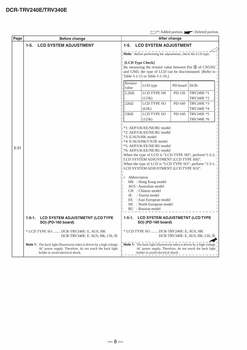
— 8 —
DCR-TRV240E/TRV340E
Page
5-31
Before change After change
: Added portion. : Deleted portion.
1-5. LCD SYSTEM ADJUSTMENT
1-5-1. LCD SYSTEM ADJUSTMETNT (LCD TYPESO) (PD-160 board)
* LCD TYPE SO ........ DCR-TRV240E: E, AUS, HKDCR-TRV340E: E. AUS, HK, CH, JE
Note 1: The back light (fluorescent tube) is driven by a high voltageAC power supply. Therefore, do not touch the back lightholder to avoid electrical shock.
1-5. LCD SYSTEM ADJUSTMENT
Note: Before performing the adjustments, check the LCD type.
[LCD Type Check]By measuring the resistor value between Pin 6 of CN5502and GND, the type of LCD can be discriminated. (Refer toTable 5-1-15 or Table 5-1-16.)
*1: AEP/UK/EE/NE/RU model*2: AEP/UK/EE/NE/RU model*3: E/AUS/HK model*4: E/AUS/HK/CN/JE model*5: AEP/UK/EE/NE/RU model*6: AEP/UK/EE/NE/RU modelWhen the type of LCD is “LCD TYPE SH”, perform“1-5-2.LCD SYSTEM ADJUSTMENT (LCD TYPE SH)”.When the type of LCD is “LCD TYPE SO”, perform “1-5-1.LCD SYSTEM ADJUSTMENT (LCD TYPE SO)”.
• AbbreviationHK : Hong Kong modelAUS : Australian modelCH : Chinese modelJE : Tourist modelEE : East European modelNE : North European modelRU : Russian model
1-5-1. LCD SYSTEM ADJUSTMETNT (LCD TYPESO) (PD-160 board)
* LCD TYPE SO ........ DCR-TRV240E: E, AUS, HKDCR-TRV340E: E. AUS, HK, CH, JE
Note 1: The back light (fluorescent tube) is driven by a high voltageAC power supply. Therefore, do not touch the back lightholder to avoid electrical shock.
Resistorvalue
2.2kΩ
22kΩ
33kΩ
LCD type
LCD TYPE SH
(123k)
LCD TYPE SO
(61K)
LCD TYPE SO
(123k)
PD board
PD-156
PD-160
PD-160
DCR-
TRV240E *1
TRV340E *2
TRV240E *3
TRV340E *4
TRV240E *5
TRV340E *6

— 9 —
DCR-TRV240E/TRV340E
Page
5-32
5-33
Before change After change
: Changed portion.
3. RGB AMP Adjustment (PD-160 board)
Mode VTR stop
Signal No signal
Measurement Point Pin 3 of CN5502 (VG)Ext. trigger: Pin 4 of CN5502 (PSIG)
Measuring Instrument Oscilloscope
Adjustment Page C
Adjustment Address 64
Specified Value A = 7.62 ± 0.05V
Note: The data of page: 0, address: 10 must be “00”.
3. RGB AMP Adjustment (PD-160 board)
Mode VTR stop
Signal No signal
Measurement Point Pin 3 of CN5502 (VG)Ext. trigger: Pin 4 of CN5502 (PSIG)
Measuring Instrument Oscilloscope
Adjustment Page C
Adjustment Address 64
Specified Value LCD TYPE SO (61K):A = 7.62±0.05V
LCD TYPE SO (123K):A = 7.44±0.05V
Note1: Refer to “LCD type check” for the discrimination of the LCDtype.
Note2: The data of page: 0, address: 10 must be “00”.
5. Contrast Adjustment (PD-160 board)
Mode VTR stop
Signal No signal
Measurement Point Pin 3 of CN5502 (VG)Ext. trigger: Pin 4 of CN5502(PSIG)
Measuring Instrument Oscilloscope
Adjustment Page C
Adjustment Address 69
Specified Value A = 2.71 ± 0.05V
Note: The data of page: 0, address: 10 must be “00”.
5. Contrast Adjustment (PD-160 board)
Mode VTR stop
Signal No signal
Measurement Point Pin 3 of CN5502 (VG)Ext. trigger: Pin 4 of CN5502(PSIG)
Measuring Instrument Oscilloscope
Adjustment Page C
Adjustment Address 69
Specified Value LCD TYPE SO (61K):A = 2.71±0.05V
LCD TYPE SO (123K):A = 2.40±0.05V
Note1: Refer to “LCD type check” for the discrimination of the LCDtype.
Note2: The data of page: 0, address: 10 must be “00”.
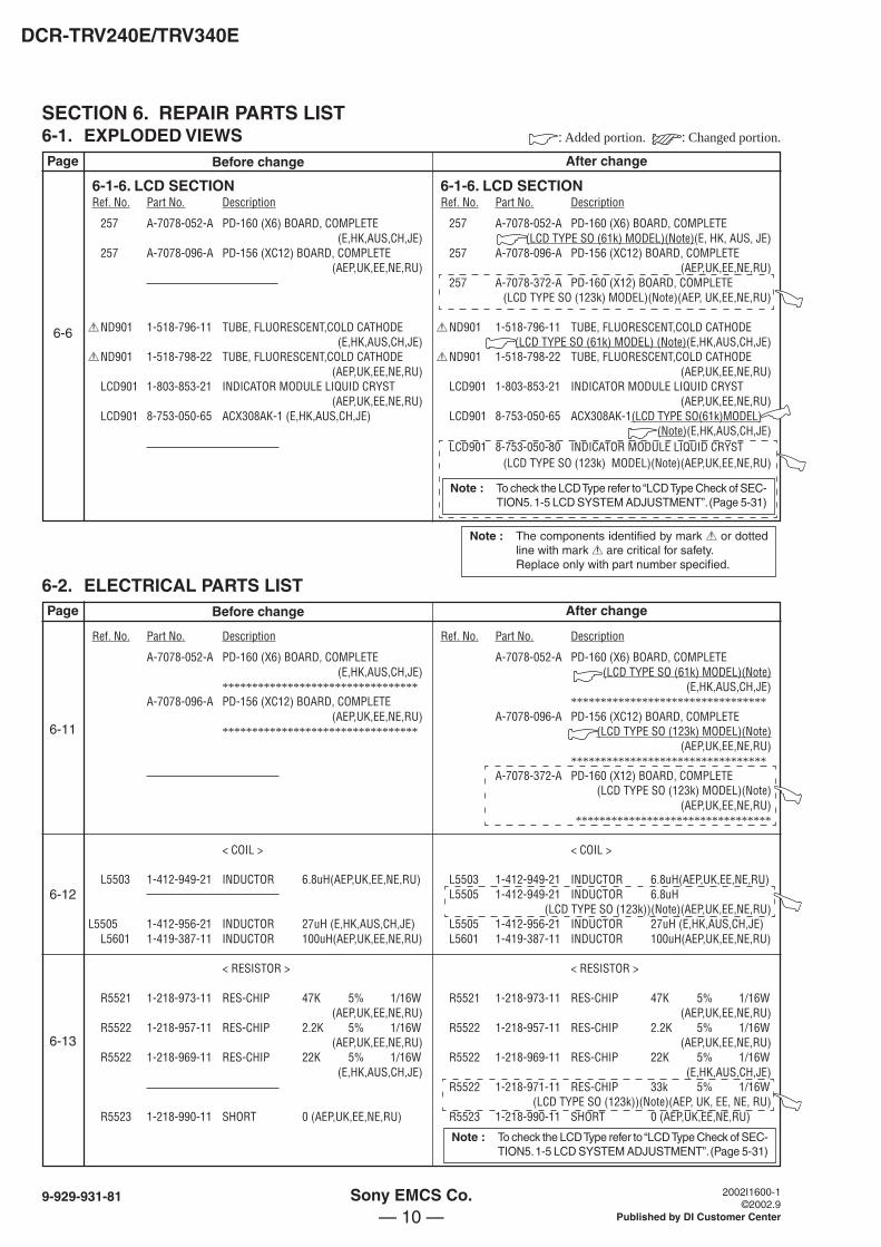
— 10 —
DCR-TRV240E/TRV340E
SECTION 6. REPAIR PARTS LIST6-1. EXPLODED VIEWSPage
6-6
Before change After change
: Added portion. : Changed portion.
6-1-6. LCD SECTION 6-1-6. LCD SECTIONRef. No. Part No. Description Ref. No. Part No. Description
257 A-7078-052-A PD-160 (X6) BOARD, COMPLETE(E,HK,AUS,CH,JE)
257 A-7078-096-A PD-156 (XC12) BOARD, COMPLETE(AEP,UK,EE,NE,RU)
0ND901 1-518-796-11 TUBE, FLUORESCENT,COLD CATHODE(E,HK,AUS,CH,JE)
0ND901 1-518-798-22 TUBE, FLUORESCENT,COLD CATHODE(AEP,UK,EE,NE,RU)
LCD901 1-803-853-21 INDICATOR MODULE LIQUID CRYST(AEP,UK,EE,NE,RU)
LCD901 8-753-050-65 ACX308AK-1 (E,HK,AUS,CH,JE)
257 A-7078-052-A PD-160 (X6) BOARD, COMPLETE(LCD TYPE SO (61k) MODEL)(Note)(E, HK, AUS, JE)
257 A-7078-096-A PD-156 (XC12) BOARD, COMPLETE(AEP,UK,EE,NE,RU)
257 A-7078-372-A PD-160 (X12) BOARD, COMPLETE(LCD TYPE SO (123k) MODEL)(Note)(AEP, UK,EE,NE,RU)
0ND901 1-518-796-11 TUBE, FLUORESCENT,COLD CATHODE(LCD TYPE SO (61k) MODEL) (Note)(E,HK,AUS,CH,JE)
0ND901 1-518-798-22 TUBE, FLUORESCENT,COLD CATHODE(AEP,UK,EE,NE,RU)
LCD901 1-803-853-21 INDICATOR MODULE LIQUID CRYST(AEP,UK,EE,NE,RU)
LCD901 8-753-050-65 ACX308AK-1(LCD TYPE SO(61k)MODEL)(Note)(E,HK,AUS,CH,JE)
LCD901 8-753-050-80 INDICATOR MODULE LIQUID CRYST(LCD TYPE SO (123k) MODEL)(Note)(AEP,UK,EE,NE,RU)
6-2. ELECTRICAL PARTS LISTBefore change After change
Ref. No. Part No. Description Ref. No. Part No. Description
A-7078-052-A PD-160 (X6) BOARD, COMPLETE(E,HK,AUS,CH,JE)
*********************************A-7078-096-A PD-156 (XC12) BOARD, COMPLETE
(AEP,UK,EE,NE,RU)*********************************
< COIL >
L5503 1-412-949-21 INDUCTOR 6.8uH(AEP,UK,EE,NE,RU)
L5505 1-412-956-21 INDUCTOR 27uH (E,HK,AUS,CH,JE)L5601 1-419-387-11 INDUCTOR 100uH(AEP,UK,EE,NE,RU)
< RESISTOR >
R5521 1-218-973-11 RES-CHIP 47K 5% 1/16W(AEP,UK,EE,NE,RU)
R5522 1-218-957-11 RES-CHIP 2.2K 5% 1/16W(AEP,UK,EE,NE,RU)
R5522 1-218-969-11 RES-CHIP 22K 5% 1/16W(E,HK,AUS,CH,JE)
R5523 1-218-990-11 SHORT 0 (AEP,UK,EE,NE,RU)
A-7078-052-A PD-160 (X6) BOARD, COMPLETE(LCD TYPE SO (61k) MODEL)(Note)
(E,HK,AUS,CH,JE)*********************************
A-7078-096-A PD-156 (XC12) BOARD, COMPLETE(LCD TYPE SO (123k) MODEL)(Note)
(AEP,UK,EE,NE,RU)*********************************
A-7078-372-A PD-160 (X12) BOARD, COMPLETE(LCD TYPE SO (123k) MODEL)(Note)
(AEP,UK,EE,NE,RU)*********************************
< COIL >
L5503 1-412-949-21 INDUCTOR 6.8uH(AEP,UK,EE,NE,RU)L5505 1-412-949-21 INDUCTOR 6.8uH
(LCD TYPE SO (123k))(Note)(AEP,UK,EE,NE,RU)L5505 1-412-956-21 INDUCTOR 27uH (E,HK,AUS,CH,JE)L5601 1-419-387-11 INDUCTOR 100uH(AEP,UK,EE,NE,RU)
< RESISTOR >
R5521 1-218-973-11 RES-CHIP 47K 5% 1/16W(AEP,UK,EE,NE,RU)
R5522 1-218-957-11 RES-CHIP 2.2K 5% 1/16W(AEP,UK,EE,NE,RU)
R5522 1-218-969-11 RES-CHIP 22K 5% 1/16W(E,HK,AUS,CH,JE)
R5522 1-218-971-11 RES-CHIP 33k 5% 1/16W(LCD TYPE SO (123k))(Note)(AEP, UK, EE, NE, RU)
R5523 1-218-990-11 SHORT 0 (AEP,UK,EE,NE,RU)
Page
6-11
6-12
6-13
Note : The components identified by mark 0 or dottedline with mark 0 are critical for safety.Replace only with part number specified.
Sony EMCS Co. 2002I1600-1 ©2002.9
Published by DI Customer Center
9-929-931-81
Note : To check the LCD Type refer to “LCD Type Check of SEC-TION5. 1-5 LCD SYSTEM ADJUSTMENT”. (Page 5-31)
Note : To check the LCD Type refer to “LCD Type Check of SEC-TION5. 1-5 LCD SYSTEM ADJUSTMENT”. (Page 5-31)
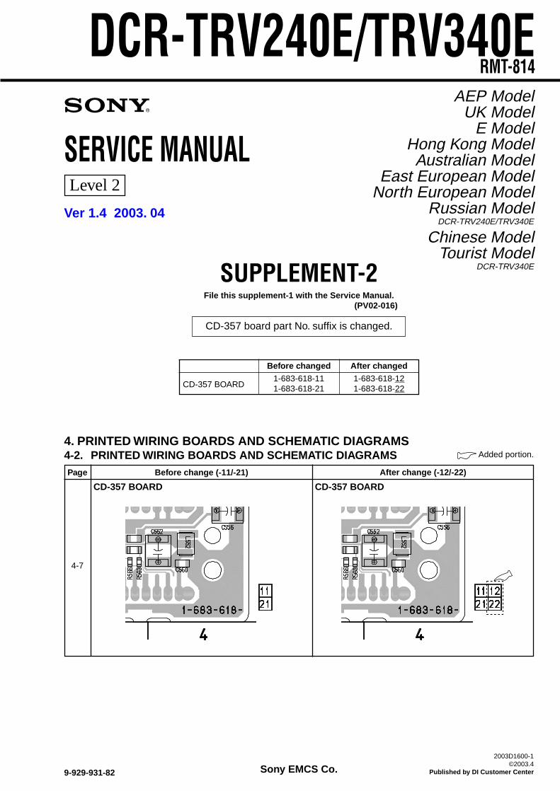
SERVICE MANUAL
SUPPLEMENT-2File this supplement-1 with the Service Manual.
(PV02-016)
Sony EMCS Co.2003D1600-1
©2003.4Published by DI Customer Center9-929-931-82
4. PRINTED WIRING BOARDS AND SCHEMATIC DIAGRAMS4-2. PRINTED WIRING BOARDS AND SCHEMATIC DIAGRAMSPage Before change (-11/-21)
4-7
CD-357 BOARD
Added portion.
After change (-12/-22)
CD-357 BOARD
DCR-TRV240E/TRV340ERMT-814
AEP ModelUK Model
E ModelHong Kong ModelAustralian Model
East European ModelNorth European Model
Russian ModelDCR-TRV240E/TRV340E
Chinese ModelTourist Model
DCR-TRV340E
Before changed After changed
CD-357 BOARD1-683-618-11 1-683-618-121-683-618-21 1-683-618-22
Ver 1.4 2003. 04
Level 2
CD-357 board part No. suffix is changed.
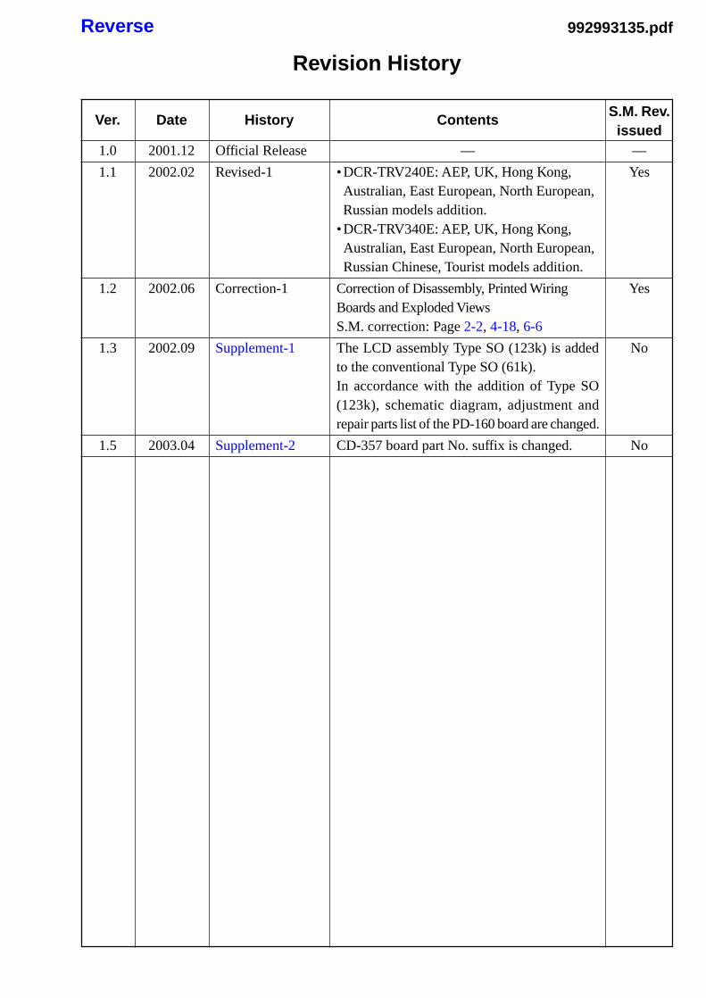
Revision History
Ver.
1.0
1.1
1.2
1.3
1.5
Date
2001.12
2002.02
2002.06
2002.09
2003.04
History
Official Release
Revised-1
Correction-1
Supplement-1
Supplement-2
Contents
—
• DCR-TRV240E: AEP, UK, Hong Kong,Australian, East European, North European,Russian models addition.
• DCR-TRV340E: AEP, UK, Hong Kong,Australian, East European, North European,Russian Chinese, Tourist models addition.
Correction of Disassembly, Printed WiringBoards and Exploded ViewsS.M. correction: Page 2-2, 4-18, 6-6
The LCD assembly Type SO (123k) is addedto the conventional Type SO (61k).In accordance with the addition of Type SO(123k), schematic diagram, adjustment andrepair parts list of the PD-160 board are changed.
CD-357 board part No. suffix is changed.
S.M. Rev.issued
—
Yes
Yes
No
No
992993135.pdfReverse


![Sony Dcr-pc350 Adjustment Ver1.0 [ET]](https://img.dokumen.tips/doc/110x75/547f5e775806b5ef5e8b4835/sony-dcr-pc350-adjustment-ver10-et.jpg)


![Sony Dcr Sr47[2]](https://img.dokumen.tips/doc/110x75/55cf9d58550346d033ad3bee/sony-dcr-sr472.jpg)