Embed Size (px)
Citation preview
SOM-4475 ETX Module
Intel® Pentium® III/Celeron® SOM-ETX CPU Module with CPU, VGA/LCD/LVDS/LAN/Audio Interface
User's Manual
ii iii
Copyright noticeThis document is copyrighted, 2002, by Advantech Co., Ltd. All rights are reserved. The original manufacturer reserves the right to make improvements to the products described in this manual at any time without notice.
No part of this manual may be reproduced, copied, translated or trans-mitted in any form or by any means without the prior written permis-sion of the original manufacturer. Information provided in this manual is intended to be accurate and reliable. However, the original manufac-turer assumes no responsibility for its use, nor for any infringements upon the rights of third parties which may result from its use.
AcknowledgementsSOM and DTOS are trademarks of Advantech Co., Ltd. AMD is a trademark of Advanced Micro Devices, Inc. Award is a trademark of Award Software International, Inc.Cyrix is a trademark of Cyrix Corporation. IBM, PC/AT, PS/2 and VGA are trademarks of International Business Machines Corporation.Intel and Pentium are trademarks of Intel Corporation.Microsoft Windows® is a registered trademark of Microsoft Corp. RTL is a trademark of Realtek Semiconductor Co., Ltd.C&T is a trademark of Chips and Technologies, Inc.UMC is a trademark of United Microelectronics Corporation.Winbond is a trademark of Winbond Electronics Corp.STPC is a trademark of SGS Thomson Corp.
For more information on this and other Advantech products, please visit our website at: http://www.advantech.com
For technical support and service, please visit our support website at: http://support.advantech.com
This manual is for the SOM-4475
Part No. 2006447500
1st Edition Printed in Taiwan Oct 2003
ii iii
Packing listBefore you begin installing your card, please make sure that the fol-lowing materials have been shipped:
• 1 SOM-4475 System On Module CPU module
• CD-ROM or Disks for utility, drivers, and manual (in PDF for mat.
• Heatsink
If any of these items are missing or damaged, contact your distributor
or sales representative immediately.
Additional Information and Assistance
1. Visit the Advantech web site at WWW.advantech.com where you can find the latest information about the product.
2. Contact your distributor, sales representative, or Advantech's customer service center for technical support if you need additional assistance.
Please have the following information ready before you call:
. Product name and serial number
. Description of your peripheral attachments
. Description of your software (operating system, version, application software, etc.)
. A complete description of the problem
. The exact wording of any error messages
iv v
Version History
October, 2003 (manual no. 2006447500)SOM-4475 User’s Manual, Ed.1
iv v
ContentsChapter 1 General Information...................................... 2
1.1 Introduction ........................................................................21.2 Specifications.......................................................................3
1.2.1 Standard System On Module functions.......................31.2.2 VGA/flat panel Interface .............................................41.2.3 Audio function............................................................41.2.4 TV-out function ..........................................................41.2.5 PCI bus Ethernet interface..........................................51.2.6 Mechanical and environmental ..................................5
1.3 Board dimensions ...............................................................6
Chapter 2 Connector Assignments ............................ 102.1 Connector Locations ........................................................102.2 Pin Assignments for X1, X2, X3, X4 connectors............ 112.3 Safety precautions ............................................................ 11
Chapter 3 Software Configuration .............................. 143.1 Introduction ......................................................................143.2 Utility CD disk ..................................................................143.3 VGA display software configuration...............................14
Table 3-1: Connections for Toshiba LTM10C042 ...........................................3.4 Connections for two standard LCDs ..............................16
3.4.1 Connections for Toshiba LTM10C042(640 x 480 TFT color LCD) .........................................................................16Table 3-1: Connections for Toshiba LTM10C042 .......................................163.4.2 Connections for Toshiba LTM12C275A (800 x 600 TFT color LCD) .................................................................17Table 3-2: Connections for Toshiba LTM12C275A.....................................17
Appendix A Watchdog Timer....................................... 20A.1 Programming the watchdog timer ..................................20

vi
Appendix B System Assignments .............................. 24B.1 System I/O ports ...............................................................24
Table B-1: System I/O ports .......................................................................24B.2 DMA channel assignments...............................................25
Table B-2: DMA channel assignments .......................................................25B.3 Interrupt assignments ......................................................26
Table B-3: Interrupt assignments ...............................................................26B.4 1st MB memory map........................................................27
Table B-4: 1st MB memory map.................................................................27

CH
AP
TE
R 1General InformationThis chapter gives background infor-mation on the SOM-4475 CPU System On Module.
Sections include:
• Introduction
• Specifications
• Board Dimensions
2 SOM-4475 User's Manual Chapter 1 General Information 3
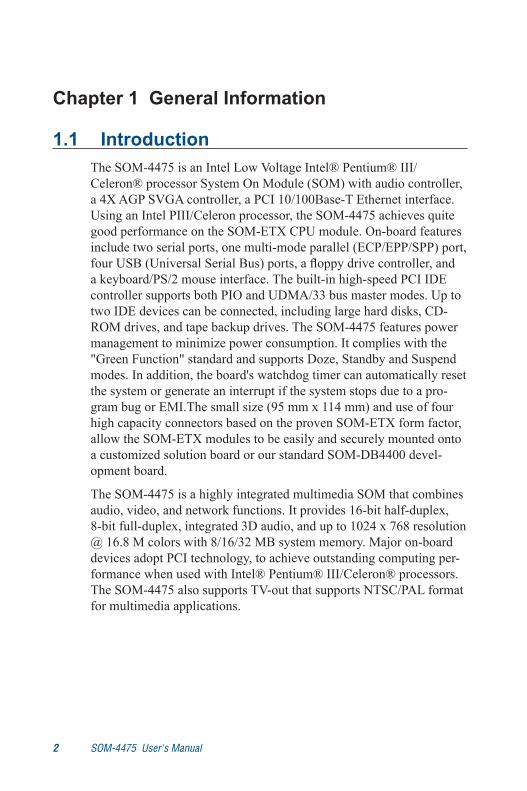
Chapter 1 General Information
1.1 IntroductionThe SOM-4475 is an Intel Low Voltage Intel® Pentium® III/Celeron® processor System On Module (SOM) with audio controller, a 4X AGP SVGA controller, a PCI 10/100Base-T Ethernet interface. Using an Intel PIII/Celeron processor, the SOM-4475 achieves quite good performance on the SOM-ETX CPU module. On-board features include two serial ports, one multi-mode parallel (ECP/EPP/SPP) port, four USB (Universal Serial Bus) ports, a floppy drive controller, and a keyboard/PS/2 mouse interface. The built-in high-speed PCI IDE controller supports both PIO and UDMA/33 bus master modes. Up to two IDE devices can be connected, including large hard disks, CD-ROM drives, and tape backup drives. The SOM-4475 features power management to minimize power consumption. It complies with the "Green Function" standard and supports Doze, Standby and Suspend modes. In addition, the board's watchdog timer can automatically reset the system or generate an interrupt if the system stops due to a pro-gram bug or EMI.The small size (95 mm x 114 mm) and use of four high capacity connectors based on the proven SOM-ETX form factor, allow the SOM-ETX modules to be easily and securely mounted onto a customized solution board or our standard SOM-DB4400 devel-opment board.
The SOM-4475 is a highly integrated multimedia SOM that combines audio, video, and network functions. It provides 16-bit half-duplex, 8-bit full-duplex, integrated 3D audio, and up to 1024 x 768 resolution @ 16.8 M colors with 8/16/32 MB system memory. Major on-board devices adopt PCI technology, to achieve outstanding computing per-formance when used with Intel® Pentium® III/Celeron® processors. The SOM-4475 also supports TV-out that supports NTSC/PAL format for multimedia applications.
2 SOM-4475 User's Manual Chapter 1 General Information 3
1.2 Specifications
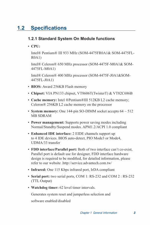
1.2.1 Standard System On Module functions
• CPU:
Intel® Pentium® III 933 MHz (SOM-4475FR0A1& SOM-4475FL-R0A1)
Intel® Celeron® 650 MHz processor (SOM-4475F-M0A1& SOM-4475FL-M0A1)
Intel® Celeron® 400 MHz processor (SOM-4475F-J0A1&SOM-4475FL-J0A1)
• BIOS: Award 256KB Flash memory
• Chipset: VIA PN133 chipset, VT8606T(TwisterT) & VT82C686B
• Cache memory: Intel ®Pentium®III 512KB L2 cache memory; Celeron® 256KB L2 cache memory on the processor
• System memory: One 144-pin SO-DIMM socket accepts 64 ~ 512 MB SDRAM
• Power management: Supports power saving modes including Normal/Standby/Suspend modes. APM1.2/ACPI 1.0 compliant
• Enhanced IDE interface: 2 EIDE channels support up to 4 IDE devices. BIOS auto-detect, PIO Mode3 or Mode4,
UDMA/33 transfer
• FDD interface/Parallel port: Both of two interface can’t co-exist, Parallel port is default use for designer, FDD interface hardware design is required to be modified, for detailed information, please refer to our website .http://service.advantech.com.tw/
• Infrared: One 115 Kbps infrared port, IrDA compliant
• Serial port: two serial ports, COM 1: RS-232 and COM 2 : RS-232 (TTL Output)
• Watchdog timer: 62 level timer intervals.
Generates system reset and jumperless selection and
software enabled/disabled
4 SOM-4475 User's Manual Chapter 1 General Information 5
• Keyboard/mouse connector: Supports standard PC/AT keyboard and PS/2 mouse interface
• USB interface: Four USB connectors compliant with USB Spec. Rev. 1.1
1.2.2 VGA/flat panel Interface
• Chipset: VIA Twister chip with integrated Savage4 2D/3D/Video Accelerator
• Frame buffer: Supports 8/16/32 MB frame buffer with system memory
• Display type: Simultaneously supports CRT and flat panel displays. Also supports up to 18-bit TFT LCD panels (SOM-4475F-
J0A1, SOM-4475F-M0A1 &SOM-4475F-R0A1) and 2 Channel LVDS interface (SOM-4475FL-R0A1, SOM-4475FL-M0A1 & SOM-4475FL-J0A1 )
• Display mode: CRT Mode: 1280 x 1024 @ 32bpp (60Hz), 1024 x 768 @ 32bpp(85Hz); LCD/Simultaneous Modes: 1280 x 1024 @16bpp(60Hz), 1024 x 768 @16bpp(60Hz)
1.2.3 Audio function
• Chipset: VIA 82C686 South Bridge
• Audio controller: AC97 Ver. 2.0 compliant interface,
Multistream Direct Sound and Direct Sound 3D acceleration
• Stereo sound: 8-bit full-duplex
• Audio interface: Microphone in, Line in, Line out
1.2.4 TV-out function
• Chipset: VIA VT1621
• Supports NTSC, NTSC=EIA (Japan) and PAL TV formats
• Provides Composite video and S-video outputs via RCA
(composite) connector and S-video connetor

4 SOM-4475 User's Manual Chapter 1 General Information 5
• Supports 640 x 480 and 800 x 600 input resolutions
• Supports Windows © 95/98/NT and Windows XP drivers
1.2.5 PCI bus Ethernet interface
• Chipset: REALTEK RTL8139 Ethernet controller
• Ethernet interface: IEEE 802.3U compatible 100/10Base-T
interface. Includes software drivers and boot ROM
1.2.6 Mechanical and environmental
• Dimensions (L x W): SOM-ETX form factor, 95 mm x 114 mm (3.7" x 4.5")
• Power supply voltage: +5 V ± 5%
• Power requirements:
Max:4.6 V@5 V
Typical 3.6 A@5 V (PIII 933 MHz + 256 MB DRAM)
Typical 3.6 A@5 V (Celeron 650 MHz + 256 MB DRAM)
Typical 3.3 A@5 V (Celeron 400 MHz + 256 MB DRAM)
• Operating temperature: 0 ~ 60° C (32 ~ 140° F)
• Operating humidity: 0% ~ 90% Relative Humidity, Noncondensing
• Weight: 0.074 Kg (weight of total package)

6 SOM-4475 User's Manual Chapter 1 General Information 7
1.3 Board dimensions
Figure 1-1: SOM-4475 dimensions

6 SOM-4475 User's Manual Chapter 1 General Information 7
Figure 1-2: SOM-4475 Top view

8 SOM-4475 User's Manual

CH
AP
TE
R 2Connector Assignments and DescriptionsThis chapter tells how to set up the SOM-4475 hardware. It includes instructions on connecting peripherals, switches and indicators. Make sure you read all the safety precautions before you begin the installation procedure.
10 SOM-4475 User's Manual Chapter 2 Connectors and Pin Assignments 11
Chapter 2 Connector Assignments
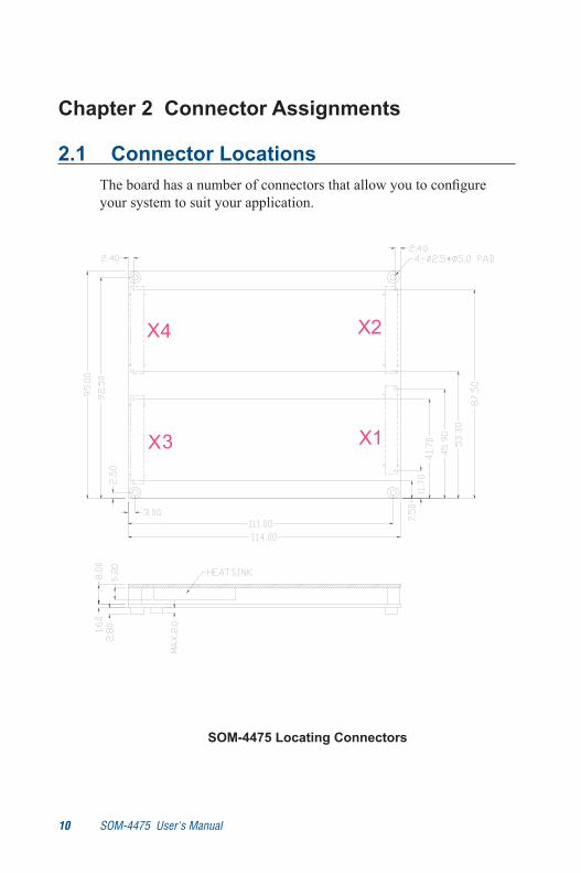
2.1 Connector LocationsThe board has a number of connectors that allow you to configure your system to suit your application.
SOM-4475 Locating Connectors
10 SOM-4475 User's Manual Chapter 2 Connectors and Pin Assignments 11
2.2 Pin Assignments for X1/2/3/4 connectorsPlease refer to SOM-ETX Design and Specification Guide, Chap-ter 2
2.3 Safety precautions
Warning! Always completely disconnect the power cord from your board whenever you are working on it. Do not make connections while the power is on, because sensitive electronic components can be damaged by a sudden rush of power.
Caution! Always ground yourself to remove any static charge before touching the board. Modern electronic de-vices are very sensitive to static electric charges. Use a grounding wrist strap at all times. Place all electronic components on a static-dissipative sur-face or in a static-shielded bag when they are not in

12 SOM-4475 User's Manual

Software Configuration (optional for SOM-4475)This chapter details the software configu-ration information. It shows you how to configure the SOM-4475 card to match your application requirements.
Sections include:
• LCD display configuration
• Connections for two standard LCDsC
HA
PT
ER 3
14 SOM-4475 User's Manual Chapter 3 Software Configuration 15
AWDFLASH.EXE 4475Vxxx.BIN
Chapter 3 Software Configuration
3.1 IntroductionThe SOM-4475 system BIOS and custom drivers are located in a 256 KB, 32-pin Flash ROM. A single Flash chip holds the system BIOS and VGA BIOS. The display type can be configured via software. This method minimizes the number of chips and eases configuration. You can change the display BIOS simply by reprogramming the Flash chip.
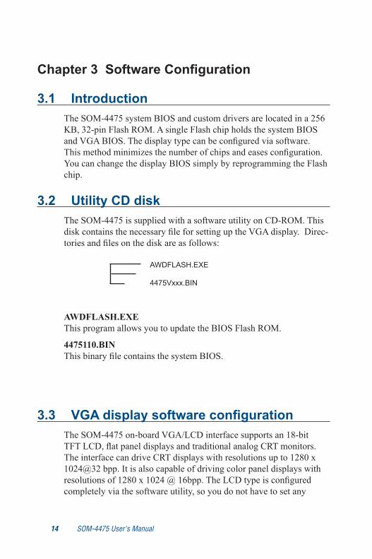
3.2 Utility CD diskThe SOM-4475 is supplied with a software utility on CD-ROM. This disk contains the necessary file for setting up the VGA display. Direc-tories and files on the disk are as follows:
AWDFLASH.EXEThis program allows you to update the BIOS Flash ROM.
4475110.BINThis binary file contains the system BIOS.
3.3 VGA display software configurationThe SOM-4475 on-board VGA/LCD interface supports an 18-bit TFT LCD, flat panel displays and traditional analog CRT monitors. The interface can drive CRT displays with resolutions up to 1280 x 1024@32 bpp. It is also capable of driving color panel displays with resolutions of 1280 x 1024 @ 16bpp. The LCD type is configured completely via the software utility, so you do not have to set any
14 SOM-4475 User's Manual Chapter 3 Software Configuration 15
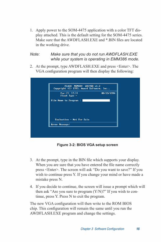
Figure 3-2: BIOS VGA setup screen
1. Apply power to the SOM-4475 application with a color TFT dis-play attached. This is the default setting for the SOM-4475 series. Make sure that the AWDFLASH.EXE and *.BIN files are located in the working drive.
Note: Make sure that you do not run AWDFLASH.EXE while your system is operating in EMM386 mode.
2. At the prompt, type AWDFLASH.EXE and press <Enter>. The VGA configuration program will then display the following:
3. At the prompt, type in the BIN file which supports your display. When you are sure that you have entered the file name correctly press <Enter>. The screen will ask “Do you want to save?” If you wish to continue press Y. If you change your mind or have made a mistake press N.
4. If you decide to continue, the screen will issue a prompt which will then ask “Are you sure to program (Y/N)?” If you wish to con-tinue, press Y. Press N to exit the program.
The new VGA configuration will then write to the ROM BIOS chip. This configuration will remain the same until you run the AWDFLASH.EXE program and change the settings.
16 SOM-4475 User's Manual Chapter 3 Software Configuration 17
3.4 Connections for two standard LCDs
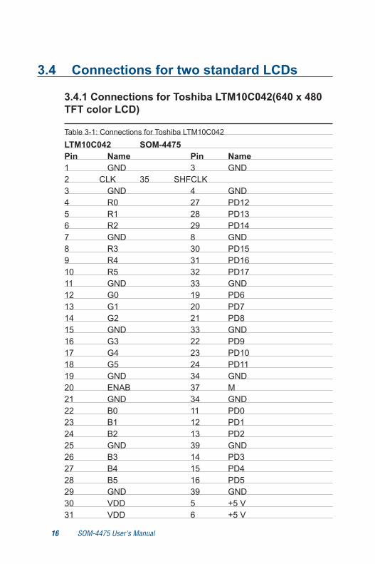
3.4.1 Connections for Toshiba LTM10C042(640 x 480 TFT color LCD)
Table 3-1: Connections for Toshiba LTM10C042
LTM10C042 SOM-4475 Pin Name Pin Name1 GND 3 GND2 CLK 35 SHFCLK3 GND 4 GND4 R0 27 PD125 R1 28 PD136 R2 29 PD147 GND 8 GND8 R3 30 PD159 R4 31 PD1610 R5 32 PD1711 GND 33 GND12 G0 19 PD613 G1 20 PD714 G2 21 PD815 GND 33 GND16 G3 22 PD917 G4 23 PD1018 G5 24 PD1119 GND 34 GND20 ENAB 37 M21 GND 34 GND22 B0 11 PD023 B1 12 PD124 B2 13 PD225 GND 39 GND26 B3 14 PD327 B4 15 PD428 B5 16 PD529 GND 39 GND30 VDD 5 +5 V31 VDD 6 +5 V

16 SOM-4475 User's Manual Chapter 3 Software Configuration 17
3.4.2 Connections for Toshiba LTM12C275A (800 x 600 TFT color LCD)
Table 3-2: Connections for Toshiba LTM12C275ALTM12C275A SOM-4475 Pin Name Pin Name
1 GND 3 GND2 NCLK 35 SHFCLK 3 NC - NC4 NC - NC5 GND 4 GND6 R0 27 PD127 R1 28 PD138 R2 29 PD149 R3 30 PD1510 R4 31 PD1611 R5 32 PD1712 GND 8 GND13 G0 19 PD614 G1 20 PD715 G2 21 PD816 G3 22 PD917 G4 23 PD1018 G5 24 PD1119 GND 33 GND20 B0 11 PD021 B1 12 PD122 B2 13 PD223 B3 14 PD324 B4 15 PD425 B5 16 PD526 ENAB 37 M/DE 27 GND 34 GND28 VCC 5 +5 V29 VCC 6 +5 V30 GND 39 GND

18 SOM-4475 User's Manual

Programming the WatchDog Timer
AP
PE
ND
IX A

20 SOM-4475 User's Manual Appendix A Watchdog Timer 21
Appendix A Watchdog Timer
A.1 Programming the watchdog timerTo program the watchdog timer, you must write a program which writes I/O port address 443 (hex). The output data is a value of time interval. The value range is from 01 (hex) to 3E (hex), and the related time interval is 1 sec. to 62 sec.
Data Time Interval
01 1 sec.
02 2 sec.
03 3 sec.
04 4 sec.
• •
• •
• •
3E 62 sec.

20 SOM-4475 User's Manual Appendix A Watchdog Timer 21
After data entry, your program must refresh the watchdog timer by rewriting the I/O port 443 (hex) while simultaneously setting it. When you want to disable the watchdog timer, your program should read I/O port 443 (hex).
The following example shows how you might program the watch-dog timer in BASIC:
10 REM Watchdog timer example program
20 OUT &H443, data REM Start and restart the watchdog
30 GOSUB 1000 REM Your application task #1,
40 OUT &H443, data REM Reset the timer
50 GOSUB 2000 REM Your application task #2,
60 OUT &H443, data REM Reset the timer
70 X=INP (&H443) REM, Disable the watchdog timer
80 END
1000 REM Subroutine #1, your application task
• •
• •
• •
1070 RETURN
2000 REM Subroutine #2, your application task
• •
• •
• •
2090 RETURN

22 SOM-4475 User's Manual
System Assignments• System I/O ports
• DMA channel assignments
• Interrupt assignments
• 1st MB memory map
AP
PE
ND
IX B
24 SOM-4475 User's Manual Appendix B System Assignments 25
Appendix B System Assignments
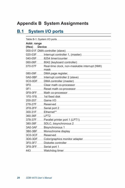
B.1 System I/O ports Table B-1: System I/O ports
Addr. range (Hex) Device000-01F DMA controller (slave)020-03F Interrupt controller 1, (master)040-05F 8254 timer/counter060-06F 8042 (keyboard controller)070-07F Real-time clock, non-maskable interrupt (NMI)
mask080-09F DMA page register,0A0-0BF Interrupt controller 2 (slave)0C0-0DF DMA controller (master)0F0 Clear math co-processor0F1 Reset math co-processor0F8-0FF Math co-processor1F0-1F8 1st fixed disk200-207 Game I/O278-27F Reserved2F8-2FF Serial port 2300-31F Ethernet**360-36F LPT2378-37F Parallel printer port 1 (LPT1)380-38F SDLC, bisynchronous 23A0-3AF Bisynchronous 13B0-3BF Monochrome display 3C0-3CF Reserved3D0-3DF Color/graphics monitor adapter3F0-3F7 Diskette controller3F8-3FF Serial port 1443 Watchdog timer
24 SOM-4475 User's Manual Appendix B System Assignments 25
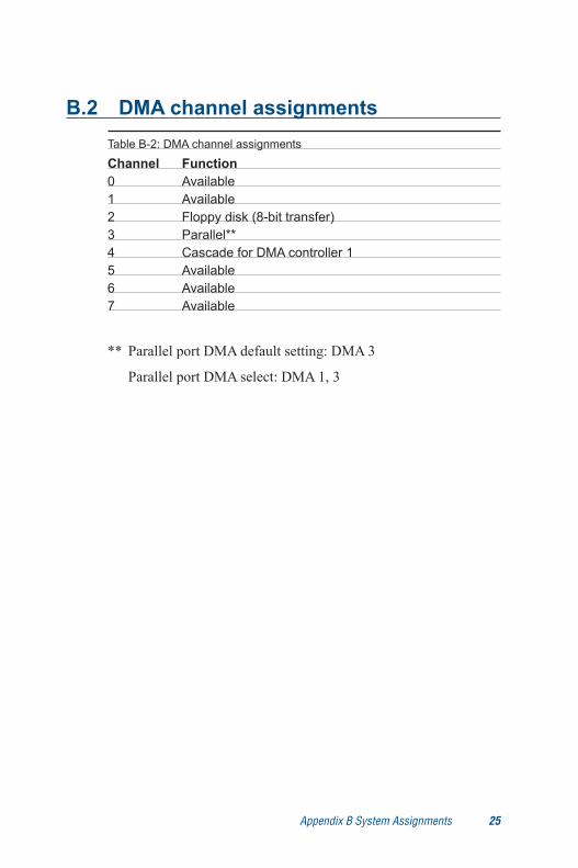
B.2 DMA channel assignmentsTable B-2: DMA channel assignments
Channel Function 0 Available1 Available2 Floppy disk (8-bit transfer)3 Parallel**4 Cascade for DMA controller 15 Available6 Available7 Available
** Parallel port DMA default setting: DMA 3
Parallel port DMA select: DMA 1, 3
26 SOM-4475 User's Manual Appendix B System Assignments 27
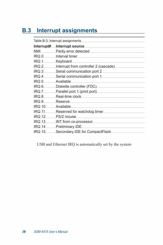
B.3 Interrupt assignmentsTable B-3: Interrupt assignments
Interrupt# Interrupt source NMI Parity error detectedIRQ 0 Interval timerIRQ 1 KeyboardIRQ 2 Interrupt from controller 2 (cascade)IRQ 3 Serial communication port 2IRQ 4 Serial communication port 1IRQ 5 AvailableIRQ 6 Diskette controller (FDC)IRQ 7 Parallel port 1 (print port)IRQ 8 Real-time clockIRQ 9 ReserveIRQ 10 AvailableIRQ 11 Reserved for watchdog timerIRQ 12 PS/2 mouseIRQ 13 INT from co-processorIRQ 14 Preliminary IDEIRQ 15 Secondary IDE for CompactFlash
USB and Ethernet IRQ is automatically set by the system
26 SOM-4475 User's Manual Appendix B System Assignments 27
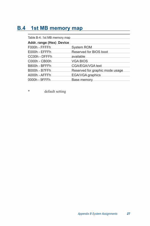
B.4 1st MB memory mapTable B-4: 1st MB memory map
Addr. range (Hex) DeviceF000h - FFFFh System ROME000h - EFFFh Reserved for BIOS bootCC00h - DFFFh available C000h - CB00h VGA BIOSB800h - BFFFh CGA/EGA/VGA textB000h - B7FFh Reserved for graphic mode usageA000h - AFFFh EGA/VGA graphics0000h - 9FFFh Base memory
* default setting
28 SOM-4475 User's Manual Appendix B System Assignments 29
IndexA
Audio Chipset 3,5,6Audio controller 5
C
Cache 3Connector Locations 12CPU types 3
D
Display Chipset 5Display modes 5Display types 5DMA channel assignments 27
I
IDE interface 3Infrared 3Interrupts 28
M
manual no iv
N
NTSC 5
P
Packing list iiiPAL 5Power management 3Programming the watchdog timer 22

28 SOM-4475 User's Manual Appendix B System Assignments 29
S
S-video 5Safety precautions 13Serial port 3System Chipset 3System I/O ports 26System memory 3
T
Toshiba LTM10C042 18Toshiba LTM12C275A 19TV-Out Chipset 5
V
VGA display configuration 16VIA VT1621 5