Embed Size (px)
DESCRIPTION
Here are the solutio
Citation preview

RESEARCH COMMUNICATIONS
CURRENT SCIENCE, VOL. 106, NO. 10, 25 MAY 2014 1414
*For correspondence. (e-mail: [email protected])
Experimental and numerical analysis on heat transfer characteristics of shoe brush-shaped fins S. Rangadinesh, M. Rajasekar, S. Arunkumar and M. Venkatesan* School of Mechanical Engineering, SASTRA University, Tirumalaisamudram, Thanjavur 613 401, India Experiments were on a shoe-brush-shaped fin consist-ing of a single bunch of splayed metal wires of circular cross-section from copper base plate. The fin was fabricated and its heat transfer characteristics were studied through experiments and numerical simula-tion. Fabrication was done through sand casting and the product was machined for required dimensions and surface finish. Numerical studies were done using ANSYS Fluent 3D. It can be inferred from the experiments and numerical studies that the fabricated fin maintains a lower base plate temperature than the rectangular flat fin and cylindrical pin fin for the same heat transfer rate, material and exposed area. Keywords: Forced convection, heat transfer, shoe brush fins, numerical simulation. FINS are extended surfaces from a heat source to enhance heat transfer by increasing the surface area exposed to the ambient. The heat transfer modes that take place between fins and the ambient are: (i) conduction within the fin, (ii) convection from the fin surface to the ambient and (iii) radiation mode of heat transfer which is negligible at lower temperatures. The above mentioned fins are called convective fins. The optimum configuration for a plate with vertical rectangular fins in natural configuration in terms of thermal conductivity, fluid properties, dimen-sions and fin absorption coefficient has been presented by de Lieto Vollaro et al.1. Lin and Lee2 obtained ideal design and operational conditions for minimal entropy generation on a flat plate-fin array for cross-flow condi-tions. El-Sayed et al.3 examined the heat transfer and fluid flow characteristics in longitudinal rectangular fin arrays by varying fin height, fin thickness, inter-fin space, fin number and fin tip to clearance of the cover-ings. They proposed a correlation to predict mean Nusselt number based upon the varied parameters and Reynolds number (Re). Jeng4 experimentally studied the variations in heat transfer and pressure drop of a diamond shaped pin fin array in a duct of rectangular size. He used tran-sient single-blow technique to predict heat transfer. Dida-rul et al.5 considered the heat transfer and fluid flow properties of short rectangular fins of aluminium material attached in 7 7 arrays. They used infrared camera to
quantify the wall temperature. They also used dye flow in a water channel and titanium oxide oil film to observe the flow behaviour. They showed that a duct of rectangular size with 20 mm height with zigzag fin array is effective. Sarma and Ramakrishna6 did a numerical study on using copper, aluminium and hybrid pin fin heat sinks. They concluded that splayed pin fins are efficient for natural convection. Rao et al.7 did an experimental and numerical study on rectangular channels having pin fin dimple stag-gered arrays for various Re numbers. They showed that the pin fin with a hollow passage has high heat transfer performance and lower friction when compared to pin fin channel. Their computational results also confirmed the same. Chabane et al.8 studied the effects of five semi-cylindrical fins on a solar air heater. They performed experiments for two air mass flow rates and found that the provision of semi-cylindrical fins improved the ther-mal efficiency. Rajesh and Balaji9 carried out experi-ments on PCM-based aluminium heat sinks with pin fins. They varied the number of pin fins within the heat sink and optimized using artificial neural network genetic hybrid algorithm. Conventionally, the fins are of flat rec-tangular shape extruding from the base plate. But these fins require high-velocity air to pass through the entire fin, resulting in more pressure drop and increased fan power. The use of straight cylindrical pin fins has over-come this problem, by offering less resistance to incom-ing air. Thus air can entrain through these fins from all directions and provides a better cooling. The present work is on developing a heat sink with finned surfaces comprising a bunch of metal wires at one end and splayed with increasing height at the other end providing more space between the fins and testing its heat transfer char-acteristics. The novelty in the present work is in splaying the fins, whereas the previous works have determined various characteristics of straight cylindrical pin fins. The splaying of fins increases their efficiency because of the increased heat transfer due to convection at the top of the fin and increased conduction from the base plate because of the close bunch of wires at the lower part of the fin. These fins are attached to the base surface by sand casting process. These types of fins find application in electronic components such as ICs and LED where heat source is very much concentrated and safe tempera-ture limit has to be maintained for reliable performance. Experiments and numerical simulation are done and the results are validated with standard results. Figure 1 shows the experimental set-up. The fabricated fin is subjected to a heat source in order to test its heat transfer characteristics. The heat source comprises of a cartridge heater connected with wires to the dimmer stat. Heat flux is varied by changing the voltage. The heater is kept inside a wooden box filled with MgO powder to dis-tribute heat uniformly. Above the powder, a copper plate is placed to spread the heat in a uniform manner because of its high thermal diffusivity. The model to be tested is

RESEARCH COMMUNICATIONS
CURRENT SCIENCE, VOL. 106, NO. 10, 25 MAY 2014 1415
fixed on the copper surface with heat sink compound (thermal paste) to reduce the contact resistance between them. In order to determine the temperature of the base plate, holes are drilled on the four sides of the base. Metal-beaded K-type thermocouples (diameter ~1.3 mm; one on each side) are kept inside the holes so that the effect of ambient interaction with the thermocouples is reduced. One thermocouple (T5) is placed on the fin tip to measure fin-tip temperature since drilling holes at the tip for the model is difficult. The fabricated model consists of 25 fins each of 20 mm height, which are bent as shown in Figure 2. The wires are bent such that they obey the equation of the parabola (y2 = 2x). The design is to increase the efficiency of the fin in which the wires put together increase the conduction heat transfer from the base plate to the bunch of wires while the splaying in-creases the rate of convection from the top of the fin. Also, the fins are designed to obey the equation in order to make the numerical modelling and experimental design
Figure 1. Experimental set-up.
Figure 2. Fabricated fin model.
simpler. The diameter of each fin is 0.335 mm, which arises from the base plate of 10 mm length, 12 mm breadth and 5 mm thickness. The specimen is tested for various velocities of air with the help of a CPU fan (12 V, 0.13 A) connected to a battery eliminator for changing the voltage to adjust the speed and thereby vary the velocity of air. The air velocity is calibrated with a vane-type anemometer kept at 75 mm from the edge of the fan, as shown in Figure 3. In the experimental set-up along with the fin, the same distance is maintained between the
Figure 3. Air speed calibration using anemometer under varying volt-ages.
Figure 4. Steady-state temperature.
Figure 5. Problem no. 7.30 from Incropera et al.10 using water for numerical validation.

RESEARCH COMMUNICATIONS
CURRENT SCIENCE, VOL. 106, NO. 10, 25 MAY 2014 1416
Figure 6. Temperature contour of the validated fin (K).
Figure 7. Temperature contour of rectangular fin (K). (Air speed = 0.2 m/s–1.)
Table 1. Validation of the numerical simulation
Average value of Tb from Tb from Ansys numerical simulation Incropera et al.10 Error (%)
39.474 K 39.5C 0.0006
test specimen and the edge of the fan. The thermocouples are connected to the data acquisition system (NI 4350 DAQ) for continuous acquisition of data. The readings are recorded after the steady state condition is reached. Results obtained are compared with the numerical solu-tions. The graph in Figure 4 shows that the steady state is reached after a particular time. The experiments are done after a steady state temperature is reached. Here T1, T2,
T3, T4 are the base plate temperatures and T5 is the fin-tip temperature. Numerical analysis of the designed fin was carried out using the CFD package ANSYS. The model was designed in the CAD tool PRO-Engineering and exported for meshing in ICEM CFD. The convective heat transfer rates and temperature variations were noted based on the governing equations solved in ANSYS Fluent solver. The numerical flow governing equations are the equation of continuity, Navier–Stokes equation of momentum and the energy equations for the modelled fluid and conduction equation for the solid fin. In order to ascertain the accuracy of numerical analysis of the method adopted, a rectangular fin with a base plate of dimensions shown in Figure 5 was modelled in

RESEARCH COMMUNICATIONS
CURRENT SCIENCE, VOL. 106, NO. 10, 25 MAY 2014 1417
ANSYS Fluent 3D. The results were compared with ana-lytical results obtained by Incropera et al.10 (Table 1). From the validation shown in Table 1, it is clear that the error is within limits (less than 1%) and the numerical method is validated. The temperature contour of the vali-dated fin is shown in Figure 6. As a further supporting study to prove that the fabri-cated fin is more efficient than the other configurations, numerical and the experimental analyses were carried out with fins of three different shapes. Experiments were done on rectangular, cylindrical and shoe brush-type fins with identical exposed areas and the results were com-pared with ANSYS 3D numerical simulation with varying air velocities and a constant heat flux of 53,750 W/m2. Experiments were done in the designed set-up for a base plate with rectangular fins. The dimensions of the base plate are: length 16 mm, breadth 20 mm, thickness 1 mm and fin height each 190 mm long, 1 mm thick. The fin of same geometry as that of the experiment was modelled and analysis done using ANSYS 3D Fluent. Numerical analysis was done for the fin at constant heat flux for various velocities. Figure 7 shows the tempera-ture contour of the rectangular fin. Maximum temperature is observed in the base plate, which is phenomenal for any heat fin-based thermal system. The tip of the fin is around 8 K less than the base plate temperature. The same fin was analysed under identical conditions and the results are given in Table 2. The K-type thermocouple was kept at five different locations and the average value calcu-lated. The numerical and experimental results showed good agreement. The rectangular fin used in the experi-ment is shown in Figure 8. The analysis was further extended to a cylindrical fin of diameter 15 mm and height 16 mm. Figure 9 shows the temperature contour of the cylindrical fin simulated in
Figure 8. Rectangular fin.
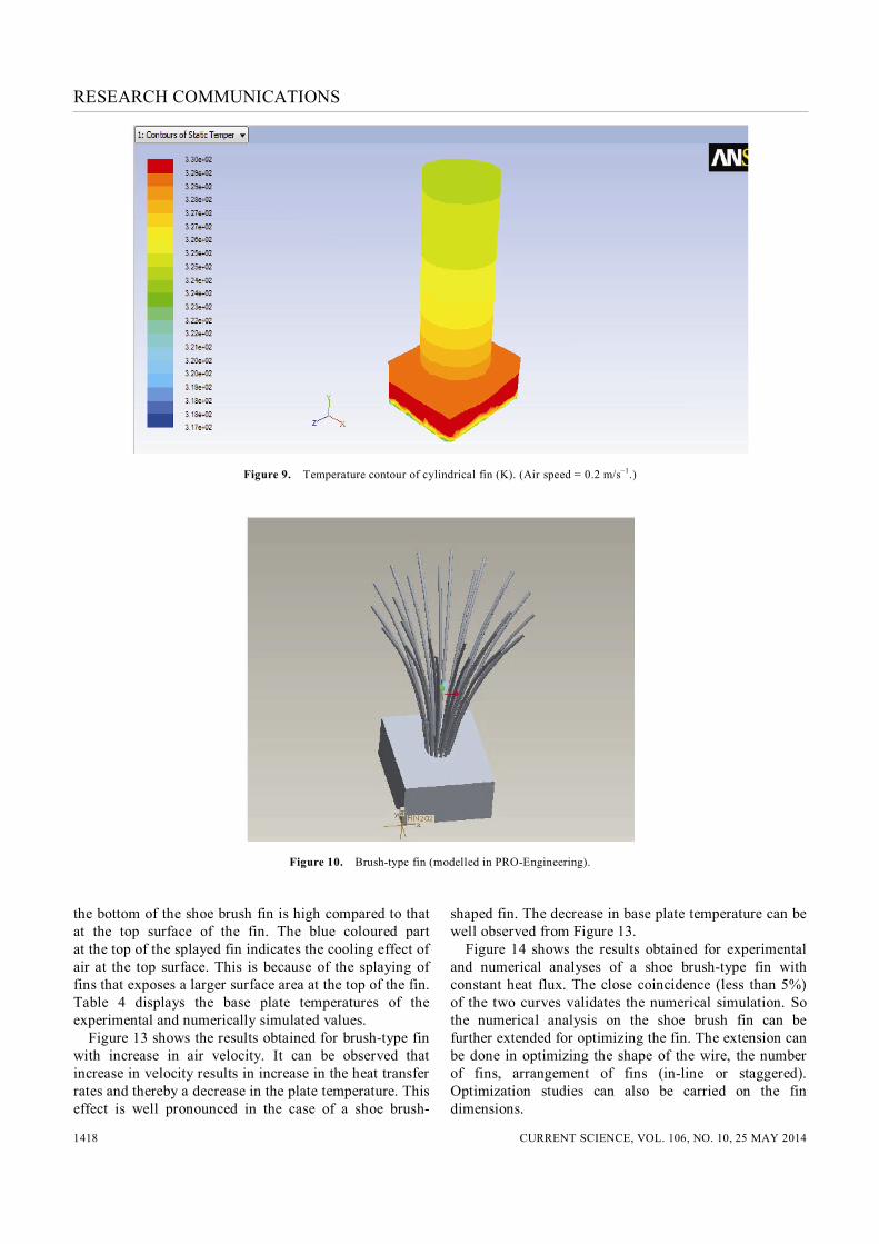
ANSYS FLUENT solver. Temperatures of the base plate corresponding to the cylindrical fin are shown in Table 3. The fabricated shoe brush fin was modelled in PRO-Engineering (Figure 10) with dimensions same as those of the experimentally fabricated fins discussed earlier. Unstructured tetrahedral meshing was done in ICEM CFD meshing tool (Figure 11). The mesh file was intro-duced into the ANSYS FLUENT and the temperature contours were obtained based on the momentum and energy equations taking the same experimental conditions over the computational domain. Fluent 3D solver was used for numerical modelling. Second-order upwind scheme was used for calculation of energy and momen-tum. The turbulence and boundary layer resolution were not taken into account because of the very low Reynolds number. The number of cells in the numerical simulation was 1,538,724. Experiments were done with the shoe brush-type fin under the same conditions as the other two types of fins. Figure 12 shows the temperature contour of the shoe brush fin. The maximum temperature is at the base plate indicated by the red colour. The temperature at
Table 2. Numerical and experimental values of solid fins
Velocity T1 T2 T3 T4 Experimental Numerical (m/s) (C) (C) (C) (C) value (C) value (C)
0.2 76.6 76.4 77.8 77.4 76.9 78.2 0.9 61.4 61.1 61.2 61.6 61.3 62.8
Table 3. Variation in base temperature in cylindrical fin
Velocity (m/s) Experimental value (C) Numerical value (C)
0.2 57.3 58.5 0.9 43.3 43.6
Table 4. Experimental and numerically simulated values of the shoe brush fin
Velocity T1 T2 T3 T4 Experimental Numerical (m/s) (C) (C) (C) (C) value (C) value (C)
0.2 49.6 50.2 50.1 51.1 50.2 52.2 0.7 44.6 45.1 44.9 46.1 45.1 46.8 0.9 40.8 41.2 40.8 42.1 41.2 42.4 1.1 39.4 39.8 39.4 40.7 39.8 40.6 1.4 37.9 38.2 37.8 39.1 38.2 39.5 1.7 36.2 36.5 36.1 37.2 36.5 36.8
Table 5. Comparison of the three types of fins
Heat flux Velocity Type of Base (W/m2) (m/s) fin temperature (C)
53,750 0.2 Wire brush fin 50 53,750 0.2 Rectangular fin 77 53,750 0.2 Cylindrical fin 57
RESEARCH COMMUNICATIONS
CURRENT SCIENCE, VOL. 106, NO. 10, 25 MAY 2014 1418
Figure 9. Temperature contour of cylindrical fin (K). (Air speed = 0.2 m/s–1.)
Figure 10. Brush-type fin (modelled in PRO-Engineering). the bottom of the shoe brush fin is high compared to that at the top surface of the fin. The blue coloured part at the top of the splayed fin indicates the cooling effect of air at the top surface. This is because of the splaying of fins that exposes a larger surface area at the top of the fin. Table 4 displays the base plate temperatures of the experimental and numerically simulated values. Figure 13 shows the results obtained for brush-type fin with increase in air velocity. It can be observed that increase in velocity results in increase in the heat transfer rates and thereby a decrease in the plate temperature. This effect is well pronounced in the case of a shoe brush-
shaped fin. The decrease in base plate temperature can be well observed from Figure 13. Figure 14 shows the results obtained for experimental and numerical analyses of a shoe brush-type fin with constant heat flux. The close coincidence (less than 5%) of the two curves validates the numerical simulation. So the numerical analysis on the shoe brush fin can be further extended for optimizing the fin. The extension can be done in optimizing the shape of the wire, the number of fins, arrangement of fins (in-line or staggered). Optimization studies can also be carried on the fin dimensions.

RESEARCH COMMUNICATIONS
CURRENT SCIENCE, VOL. 106, NO. 10, 25 MAY 2014 1419
Figure 11. a, Meshed geometry of brush-type fin. b, Meshing on the fin surface.
Figure 12. Temperature contour of wire brush fin (K). (Air speed = 0.2 m/s–1.)

RESEARCH COMMUNICATIONS
CURRENT SCIENCE, VOL. 106, NO. 10, 25 MAY 2014 1420
Figure 13. Effect of velocity of air.
Figure 14. Comparison of experimental and numerical analyses. The base temperatures of the three different types of fins are recorded and presented in Table 5. It can be in-ferred that the shoe brush fin has a lower base plate tem-perature compared to the other types of fins (rectangular and pin fin) at constant velocity of air of 0.2 m/s and con-stant heat flux of 53,750 W/m2. The brush-type fin is found to be more effective compared to the other fins. The lower base plate temperature in the shoe brush fin is because of the enhanced heat transfer resulting due to the splaying of fins. The splayed fins allow a greater surface to be exposed to air at the top of the fin. It is known that the velocity of air is maximum at the top (at maximum height from the base plate) of the fin. The reason for this is the movement of air along the height of fin because of the temperature gradient of the fin.
From the analysis carried out in this study, it can be in-ferred that the fabricated shoe brush-shaped fin maintains a lower base plate temperature than the rectangular and cylindrical pin fins for the same exposed area, material properties and ambient conditions. Solution was run till the convergence criteria (10–5 for velocity and 10–6 for energy) were reached and temperature contours have been displayed for the various models for numerical stu-dies. The numerical and experimental results were found to match reasonably well. Also, the fabricated fin main-tains a lower base temperature compared to the rectangu-lar and cylindrical fins.
1. de Lieto Vollaro, A., Grignaffini, S. and Gugliermetti, F., Opti-mum design of vertical rectangular fin arrays. Int. J. Therm. Sci., 1999, 38, 525–529.
2. Lin, W. W. and Lee, D. J., Second law analysis on a flat plate fin array under cross flow. Int. Commun. Heat Mass Transfer, 2000, 27(2), 179–190.
3. El-Sayed, S. A., Mohamed, S. M., Abdel-Latif, A. M. and Abouda, A.-H. E., Investigation of turbulent heat transfer and fluid flow in longitudinal rectangular-fin arrays of different geo-metries and shrouded fin array. Exp. Therm. Fluid Sci., 2002, 26, 879–900.
4. Jeng, T.-M., Thermal performance of in-line diamond-shaped pin fins in a rectangular duct. Int. Commun. Heat Mass Transfer, 2006, 33, 1139–1146.
5. Didarul, I. M., Kenyu, O., Minoru, Y. and Izuru, S., Study on heat transfer and fluid flow characteristics with short rectangular plate fin of different pattern. Exp. Therm. Fluid Sci., 2007, 31, 367–379.
6. Agnihothra Sarma, O. and Ramakrishna, A., CFD analysis of splayed pin fin heat sink for electronic cooling. Int. J. Eng. Res. Technol., 2012, 1(10); http://www.ijert.org/view.php?id=1849- &title=cfd-analysis-of-splayed-pin-fin-heat-sink-for-electronic- cooling
7. Rao, Y., Xu, Y. and Wan, C., An experimental and numerical study of flow and heat transfer in channels with pin fin-dimple and pin fin arrays. Exp. Therm. Fluid Sci., 2012, 38, 237–247.
8. Chabane, F., Moummi, N. and Benramache, S., Experimental study of heat transfer and thermal performance with longitudinal fins of solar air heater. J. Adv. Res., 2013, http://dx.doi.org/ 10.1016/j.jare.2013.03.001.
9. Baby, R. and Balaji, C., Thermal optimization of PCM based pin fin heat sinks: an experimental study. Appl. Therm. Eng., 2013, 54, 65–77.
10. Incropera, F. P., DeWitt, D. P., Bergman, T. L. and Lavine, A. S., Fundamentals of Heat and Mass Transfer, Wiley & Sons, Hobo-ken, NJ, USA, 2006, 6th edn.
Received 14 October 2013; revised accepted 16 April 2014