Embed Size (px)
Citation preview
x-r
ay
solutions for x-ray detection
www.andor.com
x-ray detection:
Andor Camera Solutions for X-ray DetectionAndor manufactures a comprehensive range of CCD detection systems for a wide variety of X-ray applications, both imaging andspectroscopy. These detection systems can be used at varying energy levels and are custom configured to operate either directly in avacuum chamber, attached to a chamber via a Conflat flange or as "stand-alone". In addition, if your application requires indirect detectionof X-ray, Andor offers a range of fiber-coupled cameras.
Applications that benefit from Andor’s high-end X-ray detection solutions include:
• X-ray/gamma tomography• X-ray spectroscopy• X-ray microscopy• X-ray beam profilometry• X-ray diffraction• Lithography• X-ray topography• Plasma studies• Medical imaging• Thomson scattering
Direct DetectionWith direct detection cameras, the CCDsensor itself is exposed to the incomingillumination. This enables X-ray photons to be absorbed directly in thesensitive depletion region of the CCD sensor, often creating severalelectron-hole pairs. Compared to indirect detection and traditionalX-ray film detection, this method boasts:
• Higher Quantum Efficiency (QE)• Single photon sensitivity without EMCCD & ICCD • Better spatial & energy resolution
Quantum Efficiency
QE is the probability of a photon being detected by a CCD sensor. Remember however that in direct detection of X-ray illumination, multiple photoelectrons of signal are created from a single impinging photon, often yielding single photon sensitivity.
Indirect DetectionIndirect detection is used for hard X-ray detection and when you need:
• Single photon sensitivity even with highly demagnifying tapers (EMCCD technology available)
• QE coverage that stretches well into the hard x-ray region • Large area coverage (via magnifying taper) • High dynamic range at high energy levels • Protection of the CCD sensor
With indirect detection CCDs, a phosphor coating on a fiber opticconverts X-ray photons to visible photons. Characteristics of an indirectdetection device, such as QE and spatial resolution, will depend on the parameters of the phosphor selected, such as thickness of thelayer, chemical composition and particle size.
Advantages Disadvantages
Higher dynamic range Lower spatial resolution
EMCCD compatible – singlephoton sensitivity
Lower energy resolution
Large area magnifying tapers
CCD protected by fiber-optic
Wide photon energy coverage
Advantages Disadvantages
Good spatial resolutionCannot detect hard X-rays >20keV
Single photon sensitivityUpper limit on image area(typically ~ 25x25mm)
Energy resolutionCCD "damages" progressivelyby energetic X-rays
Good QE
Linear response
High dynamic range
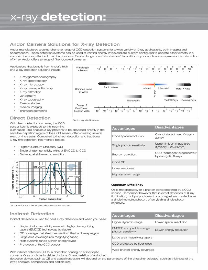
Electomagnetic Spectrum
QE curves for a number of direct detection sensor options
x-ray applications:
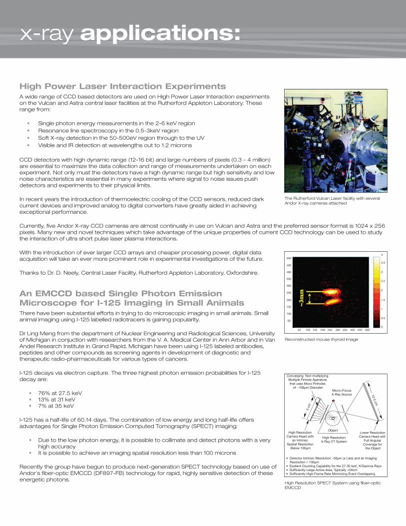
High Power Laser Interaction ExperimentsA wide range of CCD based detectors are used on High Power Laser Interaction experimentson the Vulcan and Astra central laser facilities at the Rutherford Appleton Laboratory. Theserange from:
• Single photon energy measurements in the 2-6 keV region• Resonance line spectroscopy in the 0.5-3keV region• Soft X-ray detection in the 50-500eV region through to the UV• Visible and IR detection at wavelengths out to 1.2 microns
CCD detectors with high dynamic range (12-16 bit) and large numbers of pixels (0.3 - 4 million)are essential to maximize the data collection and range of measurements undertaken on eachexperiment. Not only must the detectors have a high dynamic range but high sensitivity and lownoise characteristics are essential in many experiments where signal to noise issues pushdetectors and experiments to their physical limits.
In recent years the introduction of thermoelectric cooling of the CCD sensors, reduced darkcurrent devices and improved analog to digital converters have greatly aided in achievingexceptional performance.
Currently, five Andor X-ray CCD cameras are almost continually in use on Vulcan and Astra and the preferred sensor format is 1024 x 256pixels. Many new and novel techniques which take advantage of the unique properties of current CCD technology can be used to studythe interaction of ultra short pulse laser plasma interactions.
With the introduction of ever larger CCD arrays and cheaper processing power, digital dataacquisition will take an ever more prominent role in experimental investigations of the future.
Thanks to Dr. D. Neely, Central Laser Facility, Rutherford Appleton Laboratory, Oxfordshire.
An EMCCD based Single Photon EmissionMicroscope for l-125 Imaging in Small AnimalsThere have been substantial efforts in trying to do microscopic imaging in small animals. Smallanimal imaging using I-125 labelled radiotracers is gaining popularity.
Dr Ling Meng from the department of Nuclear Engineering and Radiological Sciences, Universityof Michigan in conjuction with researchers from the V. A. Medical Center in Ann Arbor and in VanAndel Research Institute in Grand Rapid, Michigan have been using I-125 labeled antibodies,peptides and other compounds as screening agents in development of diagnostic andtherapeutic radio-pharmaceuticals for various types of cancers.
I-125 decays via electron capture. The three highest photon emission probabilities for I-125decay are:
• 76% at 27.5 keV• 13% at 31 keV• 7% at 35 keV
I-125 has a half-life of 60.14 days. The combination of low energy and long half-life offersadvantages for Single Photon Emission Computed Tomography (SPECT) imaging:
• Due to the low photon energy, it is possible to collimate and detect photons with a very high accuracy
• It is possible to achieve an imaging spatial resolution less than 100 microns
Recently the group have begun to produce next-generation SPECT technology based on use ofAndor's fiber-optic EMCCD (DF897-FB) technology for rapid, highly sensitive detection of theseenergetic photons.
The Rutherford Vulcan Laser facility with severalAndor X-ray cameras attached
High Resolution SPECT System using fiber-opticEMCCD
Reconstructed mouse thyroid image
x-ray products:
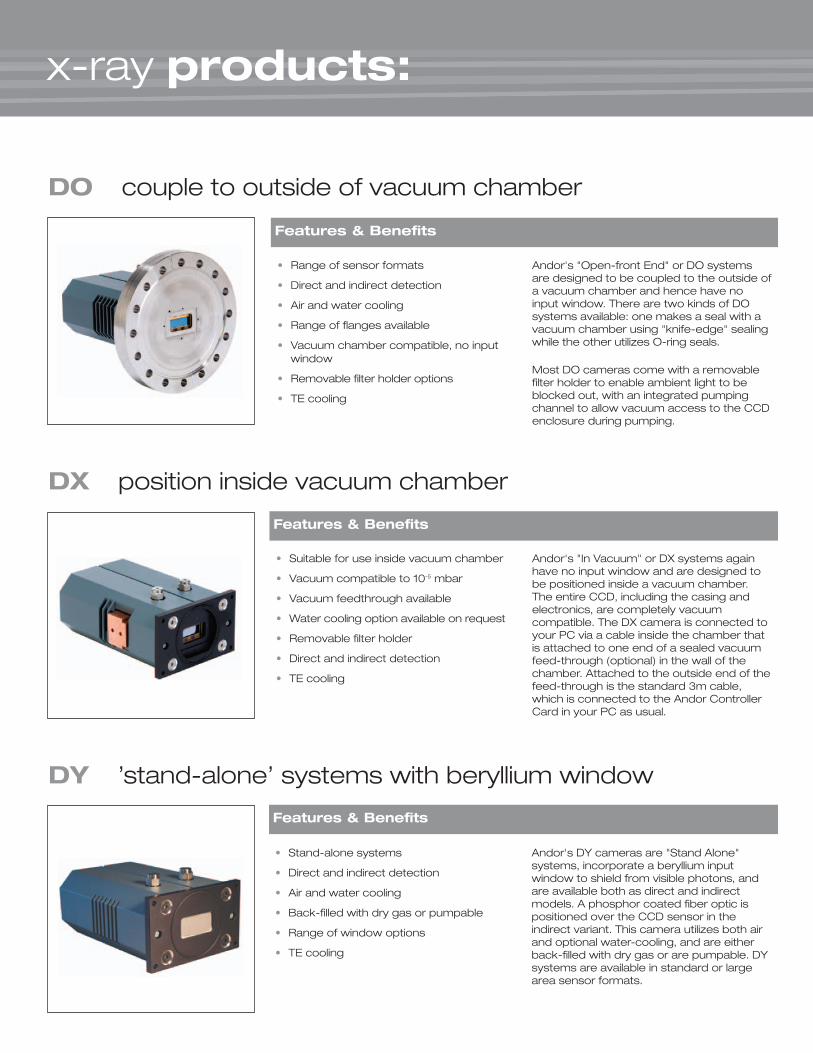
DX position inside vacuum chamber
• Range of sensor formats
• Direct and indirect detection
• Air and water cooling
• Range of flanges available
• Vacuum chamber compatible, no inputwindow
• Removable filter holder options
• TE cooling
Andor's "Open-front End" or DO systemsare designed to be coupled to the outside ofa vacuum chamber and hence have noinput window. There are two kinds of DOsystems available: one makes a seal with avacuum chamber using "knife-edge" sealingwhile the other utilizes O-ring seals.
Most DO cameras come with a removablefilter holder to enable ambient light to beblocked out, with an integrated pumpingchannel to allow vacuum access to the CCDenclosure during pumping.
• Stand-alone systems
• Direct and indirect detection
• Air and water cooling
• Back-filled with dry gas or pumpable
• Range of window options
• TE cooling
Andor's DY cameras are "Stand Alone"systems, incorporate a beryllium inputwindow to shield from visible photons, andare available both as direct and indirectmodels. A phosphor coated fiber optic ispositioned over the CCD sensor in theindirect variant. This camera utilizes both airand optional water-cooling, and are eitherback-filled with dry gas or are pumpable. DYsystems are available in standard or largearea sensor formats.
• Suitable for use inside vacuum chamber
• Vacuum compatible to 10-5 mbar
• Vacuum feedthrough available
• Water cooling option available on request
• Removable filter holder
• Direct and indirect detection
• TE cooling
Features & Benefits
Andor's "In Vacuum" or DX systems againhave no input window and are designed tobe positioned inside a vacuum chamber.The entire CCD, including the casing andelectronics, are completely vacuumcompatible. The DX camera is connected toyour PC via a cable inside the chamber thatis attached to one end of a sealed vacuumfeed-through (optional) in the wall of thechamber. Attached to the outside end of thefeed-through is the standard 3m cable,which is connected to the Andor ControllerCard in your PC as usual.
DO couple to outside of vacuum chamber
DY ’stand-alone’ systems with beryllium window
Features & Benefits
Features & Benefits
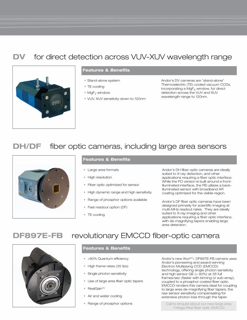
• Large area formats
• High resolution
• Fiber optic optimized for sensor
• High dynamic range and high sensitivity
• Range of phosphor options available
• Fast readout option (DF)
• TE cooling
Andor's DH fiber optic cameras are ideallysuited to X-ray detection, and otherapplications requiring a fiber optic interface.While the FO version is built around a front-illuminated interface, the FB utilizes a back-illuminated sensor with broadband ARcoating optimized for the visible region.
Andor's DF fiber optic cameras have beendesigned primarily for scientific imaging atmulti-MHz readout rates. They are ideallysuited to X-ray imaging and otherapplications requiring a fiber optic interface,with de-magnifying tapers enabling largearea detection.
• >90% Quantum efficiency
• High frame rates (35 fps)
• Single photon sensitivity
• Use of large area fiber optic tapers
• RealGainTM
• Air and water cooling
• Range of phosphor options
Andor’s new iXonEM+ DF897E-FB camera usesAndor’s pioneering and award-winningElectron Multiplying CCD (EMCCD)technology, offering single photon sensitivityand high sensor QE (> 90%) at 35 fullframes/sec (faster with binning or sub-array),coupled to a phosphor coated fiber optic.EMCCD renders this camera ideal for couplingto large area de-magnifying fiber tapers, theraw sensor sensitivity compensating forextensive photon loss through the taper.
• Stand-alone system
• TE cooling
• MgF2 window
• VUV, XUV sensitivity down to 120nm
Andor's DV cameras are "stand-alone"Thermoelectric (TE) cooled vacuum CCDs,incorporating a MgF2 window, for directdetection across the VUV and XUVwavelength range to 120nm.
DV for direct detection across VUV-XUV wavelength range
DF897E-FB revolutionary EMCCD fiber-optic camera
DH/DF fiber optic cameras, including large area sensors
Features & Benefits
Features & Benefits
Features & Benefits
Call to enquire about our new large area1 Mega Pixel fiber optic EMCCD

Exos 2 Water RecirculatorPS-150 Power Supply Unit
Solis (i) software with iXon interface
Solis (s) software with Mechelle interface
• Vacuum Feedthrough KitSpecially designed cable kit to connect a DX camera to the PCI controller card, as shown in the diagram
• PS-150 Power Supply Unit
• PS-155 Power Supply Unit
• Water Recirculator The “Exos 2” brings all new features and performance to the“chassis independent” cooling realm
• Water Chiller “OasisTM 150” ultra compact thermoelectric recirculating chiller
Selection of accessories include:
accessories configured for maximum system versatility
• Comprehensive camera control• Triggering options• Easy and accurate wavelength calibration
routines• Flexible data display – view your data in
2D, 3D, stacked & overlayed• Data export options – SIF, GRAMS, ASCII
XY, FITS• Easy automation of your experiment with
additional commands added to theAndorBasic programming language
• User defined background and data colorsallow the user to optimize the screenunder low light or low contrast monitors
• Automatic spectral line identificationagainst NIST library
• Real-time image display (video mode) idealfor aligning experiments
• Advanced data spooling direct to hard diskallowing large data sets to be acquired
• Increase your signal above the read noisefloor with RealGainTM control (EMCCDcompatible systems only)
• Kinetic series recording and playback• Through-series ROI analysis simple
generation of kinetic plots, utilizing ROIstatistics
• Real-time ROI value update, including liveplot generation
• Various real-time and playback displayoptions, including 3D profile
• Comprehensive image processing andanalysis operations
Solis (s) & Solis (i) software optimized for spectroscopy or imaging
Solis (s) - Spectroscopy Solis (i) - Imaging
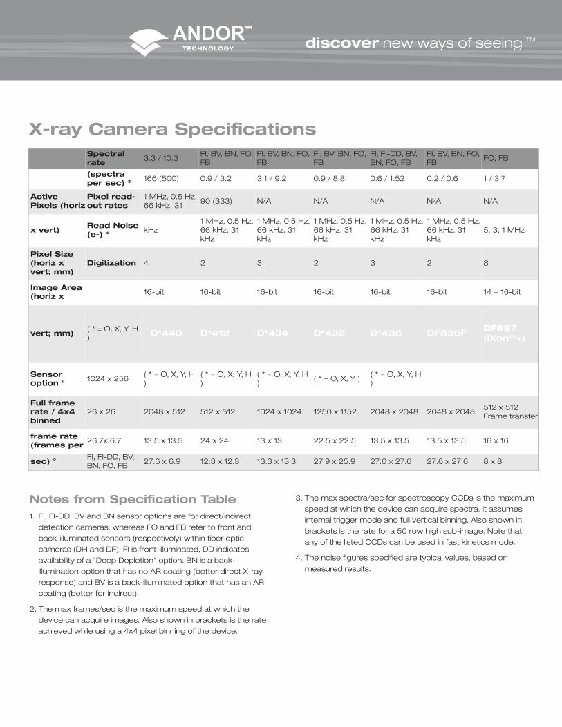
Notes from Specification Table1. FI, FI-DD, BV and BN sensor options are for direct/indirect
detection cameras, whereas FO and FB refer to front and
back-illuminated sensors (respectively) within fiber optic
cameras (DH and DF). FI is front-illuminated, DD indicates
availability of a "Deep Depletion" option. BN is a back-
illumination option that has no AR coating (better direct X-ray
response) and BV is a back-illuminated option that has an AR
coating (better for indirect).
2. The max frames/sec is the maximum speed at which the
device can acquire images. Also shown in brackets is the rate
achieved while using a 4x4 pixel binning of the device.
3. The max spectra/sec for spectroscopy CCDs is the maximum
speed at which the device can acquire spectra. It assumes
internal trigger mode and full vertical binning. Also shown in
brackets is the rate for a 50 row high sub-image. Note that
any of the listed CCDs can be used in fast kinetics mode.
4. The noise figures specified are typical values, based on
measured results.
Spectralrate
3.3 / 10.3FI, BV, BN, FO,FB
FI, BV, BN, FO,FB
FI, BV, BN, FO,FB
FI, FI-DD, BV,BN, FO, FB
FI, BV, BN, FO,FB
FO, FB
(spectraper sec) 3 166 (500) 0.9 / 3.2 3.1 / 9.2 0.9 / 8.8 0.6 / 1.52 0.2 / 0.6 1 / 3.7
ActivePixels (horiz
Pixel read-out rates
1 MHz, 0.5 Hz,66 kHz, 31
90 (333) N/A N/A N/A N/A N/A
x vert)Read Noise(e-) 4 kHz
1 MHz, 0.5 Hz,66 kHz, 31kHz
1 MHz, 0.5 Hz,66 kHz, 31kHz
1 MHz, 0.5 Hz,66 kHz, 31kHz
1 MHz, 0.5 Hz,66 kHz, 31kHz
1 MHz, 0.5 Hz,66 kHz, 31kHz
5, 3, 1 MHz
Pixel Size(horiz xvert; mm)
Digitization 4 2 3 2 3 2 8
Image Area(horiz x D*420 16-bit 16-bit 16-bit 16-bit 16-bit 16-bit 14 + 16-bit
vert; mm)( * = O, X, Y, H) D*440 D*412 D*434 D*432 D*436 DF836F
DF897(iXonEM+)
Sensoroption 1 1024 x 256
( * = O, X, Y, H)
( * = O, X, Y, H)
( * = O, X, Y, H)
( * = O, X, Y )( * = O, X, Y, H)
Full framerate / 4x4binned
26 x 26 2048 x 512 512 x 512 1024 x 1024 1250 x 1152 2048 x 2048 2048 x 2048512 x 512Frame transfer
frame rate(frames per
26.7x 6.7 13.5 x 13.5 24 x 24 13 x 13 22.5 x 22.5 13.5 x 13.5 13.5 x 13.5 16 x 16
sec) 2 FI, FI-DD, BV,BN, FO, FB
27.6 x 6.9 12.3 x 12.3 13.3 x 13.3 27.9 x 25.9 27.6 x 27.6 27.6 x 27.6 8 x 8
X-ray Camera Specifications
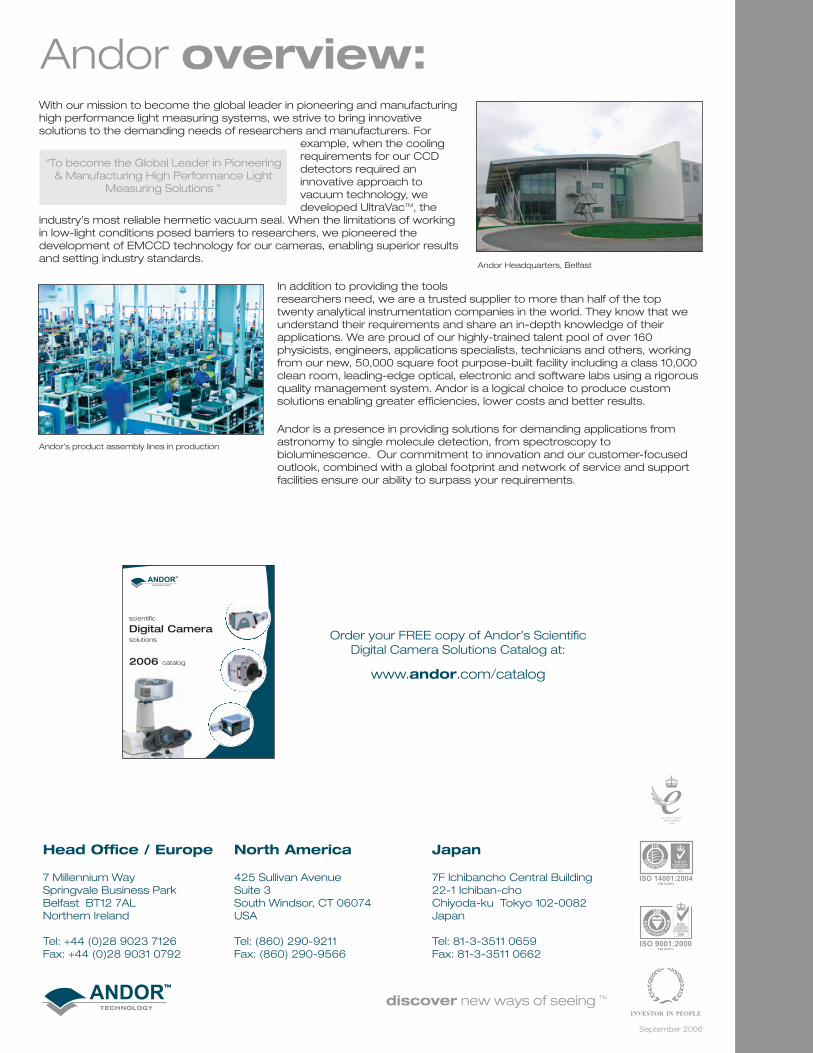
With our mission to become the global leader in pioneering and manufacturinghigh performance light measuring systems, we strive to bring innovativesolutions to the demanding needs of researchers and manufacturers. For
example, when the coolingrequirements for our CCDdetectors required aninnovative approach tovacuum technology, wedeveloped UltraVacTM, the
industry’s most reliable hermetic vacuum seal. When the limitations of workingin low-light conditions posed barriers to researchers, we pioneered thedevelopment of EMCCD technology for our cameras, enabling superior resultsand setting industry standards.
In addition to providing the toolsresearchers need, we are a trusted supplier to more than half of the toptwenty analytical instrumentation companies in the world. They know that weunderstand their requirements and share an in-depth knowledge of theirapplications. We are proud of our highly-trained talent pool of over 160physicists, engineers, applications specialists, technicians and others, workingfrom our new, 50,000 square foot purpose-built facility including a class 10,000clean room, leading-edge optical, electronic and software labs using a rigorousquality management system. Andor is a logical choice to produce customsolutions enabling greater efficiencies, lower costs and better results.
Andor is a presence in providing solutions for demanding applications fromastronomy to single molecule detection, from spectroscopy tobioluminescence. Our commitment to innovation and our customer-focusedoutlook, combined with a global footprint and network of service and supportfacilities ensure our ability to surpass your requirements.
“To become the Global Leader in Pioneering& Manufacturing High Performance Light
Measuring Solutions ”
Andor overview:
Andor Headquarters, Belfast
Andor’s product assembly lines in production
Head Office / Europe
7 Millennium WaySpringvale Business ParkBelfast BT12 7ALNorthern Ireland
Tel: +44 (0)28 9023 7126Fax: +44 (0)28 9031 0792
North America
425 Sullivan AvenueSuite 3South Windsor, CT 06074USA
Tel: (860) 290-9211Fax: (860) 290-9566
Japan
7F Ichibancho Central Building22-1 Ichiban-choChiyoda-ku Tokyo 102-0082Japan
Tel: 81-3-3511 0659Fax: 81-3-3511 0662
September 2006
Order your FREE copy of Andor’s ScientificDigital Camera Solutions Catalog at:
www.andor.com/catalog