Embed Size (px)
Citation preview

Solutions for Structural Concrete
Cast-In Anchoring Solutions
Design Manual
TM
R E I N F O R C I N G • P R E C A S T • T I L T - U P
TM

TM
R E I N F O R C I N G • P R E C A S T • T I L T - U P
2

Reid™ has been supplying quality engineered products to the Australian mining and construction industries since the 1920’s, and in the last 50 years has built a position of market leadership in the supply of cast-in components to concrete construction sector.
Reid™ introduced the revolutionary SwiftLift™ system, involving robust cast-in anchors and safe, quick release clutches. This unique system greatly increased safety and efficiency in the transportation and placement of large concrete components such as wall panels, stairs, beams and pipes.
Reid™ innovation continued with the development of the ReidBar™ system - ReidBar™ Couplers, Grouters and Inserts that are used with ReidBar™ - continuously threaded Grade 500 reinforcing steel produced in Australia and New Zealand. These products are now widely used to enable fast, easy and efficient reinforcement connections on major construction projects throughout all markets.
Reid’s ongoing commitment to innovation and investment in better products, systems and services was further strengthened when the business became a part of the global ITW Group in 2004. This gives Reid people access to significant technology and business resources worldwide, the benefits of which flow to our customers.
In partnership with another ITW group member – Ramset™, we can deliver lifting, connection, anchorage and fixing solutions for anything built from concrete.
At Reid™ we aim to be much more than just a supplier of components to the concrete construction industry. We work in partnership with our customers in all facets of planning, preparation, design, engineering certification, forming, production, rigging, lifting, anchoring and bracing… all critical stages in the safe and efficient manufacture and placement of concrete elements.
Our products help handle the physical load, whilst our professional support services help lift the risk load – each Reid design comes backed by the strength of ITW, and our absolute commitment to delivering your project faster, safer, more efficiently.
This design guide is a practical demonstration of that commitment – we hope you find it useful.
Engineering and technical representation in all capital cities and regional centres.
Extensive technical data and support available.
- ISO9001 accredited
- strict quality control systems
- products designed in Australia to Australian Standards
- products tested in Australian building materials
- full responsibility for our product range and performance data
3

All structural products and systems require suitable engineering in their development and manufacture. In the case of construction projects and one-off solutions these are customised for the specific problem or requirement and usually involve extra time and cost to devise, certify and supply. In the case of standardised/ready-to-use products however, as offered to the industry by Reid™, these pre-engineered products also require customised application-engineering to devise and specify arrangements of standard product to deliver best-possible solutions to every unique, project-based problem and structural requirement. This approach nearly always allows the fastest and best-value solutions to the customer’s needs and so is inherently better engineering.
This engineering resource from Reid™ is intended to supply what you need to know to get the solutions you need from the products we offer. You can either solve the problem for yourself or get any necessary assistance from Reid™.
Engineered Solutions
Extensive research, development and testing are invested in Reid™
products. This provides designers with the complete performance
capabilities of the Reid™ range of Cast-In Ferrules.
The performance data contained in this Design Guide relates only to
the Reid™ range of Cast-In Ferrules. Our superior steel grade and
manufacturing tolerances are key factors in producing our excellent
products. Generic products may appear similar physically, but their
actual performance is heavily influenced by the steel grade and
manufacturing tolerances used.
4

WE HAVE MORE ENGINEERING RESOURCES THAN CAN BE CONTAINED WITHIN THIS DESIGN GUIDE, SO, IF YOU WANT TO
KNOW MORE OR JUST WANT TO KNOW THAT REID™ CAN SOLVE IT FOR YOU, CALL YOUR REID™ ENGINEER FOR ASSISTANCE:
The goal of this process is to deliver the best possible combination of required safety, managed risk and best value performance for the designer and the downstream construction staff.
NSW/ACT: 0438 540 482
QLD/NT: 0407 510 079
VIC: 0419 164 066
SA/TAS: 0409 672 943
WA: (08) 9455 3622
Some structural products supplied by Reid™ in conjunction with our own systems are sourced from our allied Business Unit – Ramset™. In such cases your Reid™ engineer can refer you to the appropriate engineering resources for these products. Whatever the information source Reid™ will only propose solutions which we know will work best for you and we take full responsibility for all products that we supply – be it the hardware or our engineering service. We hope you’ll agree that we do this better than anybody else.
IDENTIFY THE POTENTIAL SYSTEMS THAT WILL WORK1. Options
FOR THE EFFICIENT APPLICATION OF THE SPECIFIC PRODUCT CHOICE3. Design
THE OPTION THAT BEST MEETS ALL THE REQUIREMENTS2. Choose
THE SOLUTION CORRECTLY SO IT’S CLEAR WHAT NEEDS TO BE DONE4. Specify
Once you have adequately defined the application/problem the essential steps to getting the right Reid™ solution are:
5
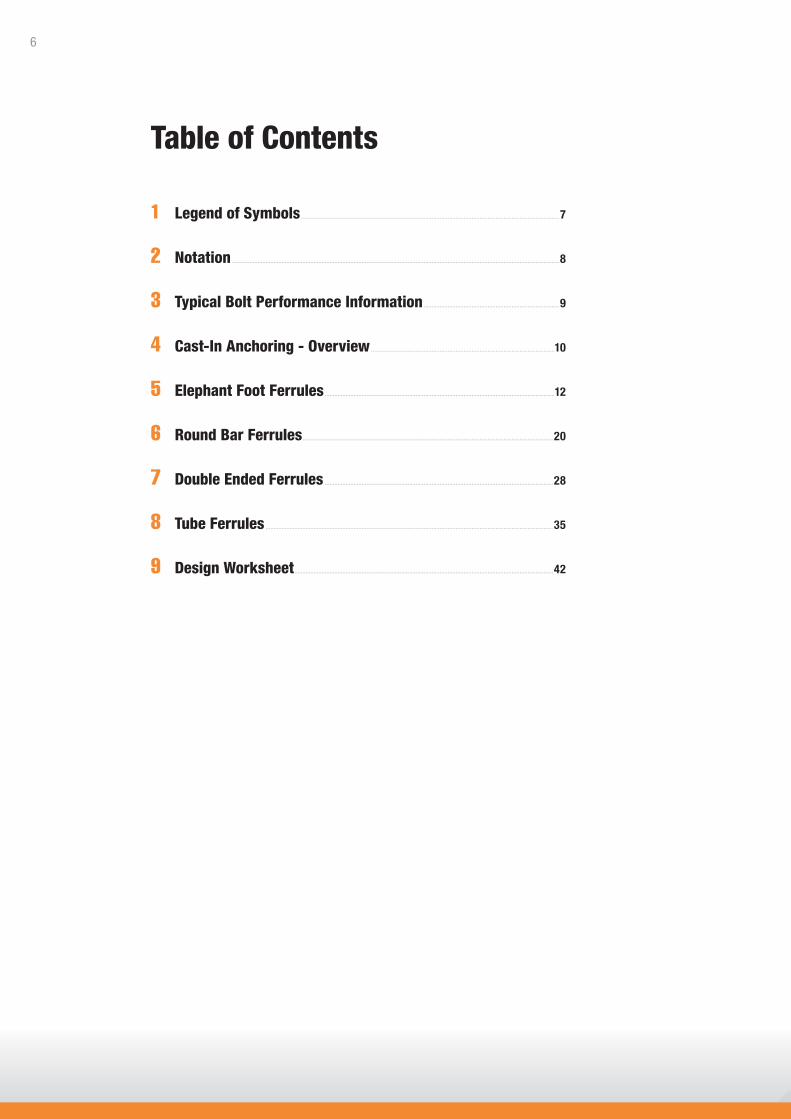
1 Legend of Symbols ..................................................................................................................................................................7
2 Notation .............................................................................................................................................................................................................8
3 Typical Bolt Performance Information .....................................................................................9
4 Cast-In Anchoring - Overview ...................................................................................................................10
5 Elephant Foot Ferrules ................................................................................................................................................12
6 Round Bar Ferrules .............................................................................................................................................................20
7 Double Ended Ferrules ...............................................................................................................................................28
8 Tube Ferrules ....................................................................................................................................................................................35
9 Design Worksheet ..................................................................................................................................................................42
Table of Contents
6

Suitable for elevated temperate applications. Structural anchor components made from steel. Any plastic or non-ferrous parts make no contribution to holding power under elevated temperatures.
Suitable for use in seismic design.
Anchor has an effective pull-down feature,or is a stud anchor. It has the ability to clamp the fixture to the base material and provide high resistance to cyclic loading.
Has good resistance to cyclic and dynamic loading. Resists loosening under vibration.
May be used close to edges (or another anchor) without risk of splitting the concrete.
Suitable for wall applications.
Suitable for overhead applications.
Suitable for floor applications. Chemical anchors suitable for use in dry holes.
PERFORMANCE RELATED SYMBOLSIndicates the suitability of product to specific types of performance related situations.
MATERIAL SPECIFICATION SYMBOLSIndicates the base material and surface finish to assist in selection with regard to corrosion or environmental issues.
INSTALLATION RELATED SYMBOLSIndicates the suitable positioning and other installation related requirements.
AISI Grade 316 Stainless Steel - Resistant to corrosive agents including chlorides and industrial pollutants. Recommended for internal or external applications in marine or corrosive environments.
Steel Zinc Plated to AS1789-2003.Recommended for internal applications only.
Steel Hot Dipped Galvanised to AS4680-2006. For external applications.
Stainless Steel - Resistant to corrosive agents.Recommended for internal or external applications.
We have developed this set of easily recognisable icons to assist with product selection.
1 Legend of Symbols
7

GENERAL NOTATIONa = actual anchor spacing (mm)ac = critical anchor spacing (mm)am = absolute minimum anchor spacing (mm)Ab = reinforcing bar stress area (mm2)As = stress area (mm2)Ast = stress area of reinforcing bar (mm2)bm = minimum substrate thickness (mm)db = bolt diameter (mm)df = fixture hole diameter (mm)dh = drilled hole diameter (mm)e = actual edge distance (mm)ec = critical edge distance (mm)em = absolute minimum edge distance (mm)f’c = concrete cylinder compressive
strength (MPa)f’cf = concrete flexural tensile strength (MPa)fsy = reinforcing bar steel yield strength
(N/mm2)fu = characteristic ultimate steel
tensile strength (MPa)fy = characteristic steel yield strength (MPa)h = anchor effective depth (mm)hn = nominal effective depth (mm)
g = gap or non-structural thickness (mm)k1 = see AS3600 - 2001k2 = see AS3600 - 2001L = anchor length (mm)Le = anchor effective length (mm)Lst = length of reinforcing bar to develop
tensile stress σst (mm)Lsy.t = reinforcing bar length to develop
steel yield in tension (mm)Lsy.t (nom) = length of reinforcing bar to develop
full steel yield in 32 MPa concrete(mm)
Lt = thread length (mm)n = number of fixings in a groupNsy = tensile steel yield load capacityNub = characteristic ultimate tensile
adhesive bond capacity (kN)PL = long term, retained preload (kN)PLi = initial preload (kN)Pr = proof load (kN)t = total thickness of fastened
material(s) (mm)Tr = assembly torque (Nm)Xe = edge distance effect, tension
Xna = anchor spacing effect, tensionXnae = anchor spacing effect, end of a row,
tensionXnai = anchor spacing effect, internal to a row,
tensionXnc = concrete compressive strength effect,
tensionXne = edge distance effect, tensionXuc = characteristic ultimate capacityXva = anchor spacing effect, concrete edge shearXvc = concrete compressive strength effect, shearXvd = load direction effect, concrete edge shearXvn = multiple anchors effect, concrete edge shearXvs = corner edge shear effect, shearXvsc = concrete compressive strength effect,
combined concrete/steel shearZ = section modulus (mm3)ß = concrete cube compressive
strength (N/mm2)µT = torque co-efficient of sliding frictionx = mean ultimate capacityσst = steel tensile stressσst (nom) = steel tensile stress of reinforcing bar
bonded into 32 MPa concrete
STRENGTH LIMIT STATE NOTATIONM* = design bending action effect (Nmm)Mu = characteristic ultimate moment
capacity (Nm)N* = design tensile action effect (kN)Ntf = nominal ultimate bolt tensile capacity (kN)Nu = characteristic ultimate tensile
capacity (kN)Nuc = characteristic ultimate concrete
tensile capacity (kN)Nucr = factored characteristic ultimate
concrete tensile capacity (kN)Nur = design ultimate tensile capacity (kN)Nurc = design ultimate concrete tensile
capacity (kN)Nus = characteristic ultimate steel tensile
capacity (kN)
Nusr = factored characteristic ultimate steel tensile capacity (kN)
Ru = characteristic ultimate capacityV* = design shear action effect (kN)Vsf = nominal ultimate bolt shear capacity (kN)Vu = ultimate shear capacity (kN)Vuc = characteristic ultimate concrete
edge shear capacity (kN)Vur = design ultimate shear capacity (kN)Vurc = design ultimate concrete edge shear
capacity (kN)Vus = characteristic ultimate steel shear
capacity (kN)Vusc = characteristic ultimate combined
concrete/steel shear capacity (kN)
Ø = capacity reduction factorØc = capacity reduction factor, concrete
tension recommended as 0.6Øm = capacity reduction factor, steel bending
recommended as 0.8Øn = capacity reduction factor, steel tension
recommended as 0.8Øq = capacity reduction factor, concrete edge
shear recommended as 0.6Øv = capacity reduction factor, steel shear
recommended as 0.8
PERMISSIBLE STRESS NOTATIONfs = factor of safetyfsc = factor of safety for substrate = 3.0fss = factor of safety for steel in tension
and bending = 2.2fsv = factor of safety for steel in shear = 2.5M = applied moment (Nm)Ma = working load limit moment capacity (Nm)N = applied tensile load (kN)
Na = working load limit tensile capacity (kN)Nac = working load limit concrete tensile
capacity (kN)Nar = factored working load limit tensile
capacity (kN)Nas = working load limit steel tensile
capacity (kN)Nasr = factored working load limit steel
tensile capacity (kN)
Ra = working load limit capacityV = applied shear load (kN)Va = working load limit shear capacity (kN)Var = factored working load limit shear
capacity (kN)Vas = working load limit steel shear
capacity (kN)
2 Notation
8
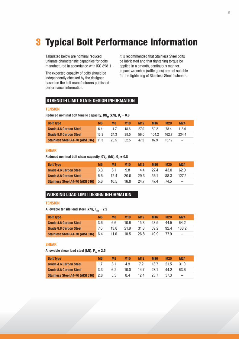
3 Typical Bolt Performance InformationTabulated below are nominal reduced ultimate characteristic capacities for bolts manufactured in accordance with ISO 898-1.
The expected capacity of bolts should be independently checked by the designer based on the bolt manufacturers published performance information.
STRENGTH LIMIT STATE DESIGN INFORMATION
TENSION
Reduced nominal bolt tensile capacity, ØNtf (kN), Øn = 0.8
Bolt Type M6 M8 M10 M12 M16 M20 M24
Grade 4.6 Carbon Steel 6.4 11.7 18.6 27.0 50.2 78.4 113.0
Grade 8.8 Carbon Steel 13.3 24.3 38.5 56.0 104.2 162.7 234.4
Stainless Steel A4-70 (AISI 316) 11.3 20.5 32.5 47.2 87.9 137.2 –
SHEAR
Reduced nominal bolt shear capacity, ØVsf (kN), Øv = 0.8
Bolt Type M6 M8 M10 M12 M16 M20 M24
Grade 4.6 Carbon Steel 3.3 6.1 9.8 14.4 27.4 43.0 62.0Grade 8.8 Carbon Steel 6.6 12.4 20.0 29.3 56.1 88.3 127.2Stainless Steel A4-70 (AISI 316) 5.6 10.5 16.8 24.7 47.4 74.5 –
WORKING LOAD LIMIT DESIGN INFORMATION
TENSION
Allowable tensile load steel (kN), Fss = 2.2
Bolt Type M6 M8 M10 M12 M16 M20 M24
Grade 4.6 Carbon Steel 3.6 6.6 10.6 15.3 28.5 44.5 64.2Grade 8.8 Carbon Steel 7.6 13.8 21.9 31.8 59.2 92.4 133.2Stainless Steel A4-70 (AISI 316) 6.4 11.6 18.5 26.8 49.9 77.9 –
SHEAR
Allowable shear load steel (kN), Fsv = 2.5
Bolt Type M6 M8 M10 M12 M16 M20 M24
Grade 4.6 Carbon Steel 1.7 3.1 4.9 7.2 13.7 21.5 31.0Grade 8.8 Carbon Steel 3.3 6.2 10.0 14.7 28.1 44.2 63.6Stainless Steel A4-70 (AISI 316) 2.8 5.3 8.4 12.4 23.7 37.3 –
It is recommended that Stainless Steel bolts be lubricated and that tightening torque be applied in a smooth, continuous manner. Impact wrenches (rattle guns) are not suitable for the tightening of Stainless Steel fasteners.
9

Panel Connections Design
Reid™ serves the industry not just with supply of hardware but, and perhaps more importantly,
with technically superior engineering information, such as this design guide. This has proven to
be a valued asset for professional engineers, allowing for informed, safe and efficient decisions,
with the reassurance that the published capacities have been verified over years of extensive
research, development and testing.
The following design information is provided for the guidance of qualified structural engineers
or other suitably skilled persons in the design of cast-in anchors and allows the designer to
determine load carrying capacities based on actual application and installation conditions.
The Simplified Design Approach to achieve strength limit state design was developed by our
business partner – Ramset™ and has proven to be a simple and effective method to allow for
rapid selection of a suitable anchor through systematic analysis, ensuring that it will meet the
required design criteria under strength limit state principles.
The Reid™ Cast-In ferrule range is available in Zinc, Hot Dip Galvanised and Stainless Steel
finishes to cater for a wide range of atmospheric conditions and range in sizing from M10
through to M24.
4 Cast-In Anchoring - Overview
10

11

db
Lt
L
ProductThe Elephant Foot Ferrule is a premium grade, medium to heavy duty, cast-in ferrule.
Benefits, Advantages and FeaturesImproved Security:• No cross bar required to develop rated capacity.
High Quality Material Options:• 5.8 grade.• 42 micron hot dip galvanised.• Premium 316 SS.
Versatile:• Use in near or far face applications with our
range of accessories.• May be used with small rebar for fixing to mesh.
GENERAL INFORMATION
1. Chair for tilt-cast.2. Nailing plate or bolted to formwork.3. Fixing to steel casting bed with magnetic or glue on nailing plate.4. “Puddled” into wet concrete.5. Templated onto face of panel.
1 4 5 2 3
PERFORMANCE RELATED MATERIAL INSTALLATION RELATEDPerformance Related
Principal Applications
PERFORMANCE RELATED MATERIAL INSTALLATION RELATEDPERFORMANCE RELATED MATERIAL INSTALLATION RELATED
A4316
Material
PERFORMANCE RELATED MATERIAL INSTALLATION RELATEDInstallation Related
• Small and lightweight precast fixing point.
• Structural connections.
• Curtain wall and panel facade fixings.
• Temporary precast panel bracing points.
5 Elephant Foot Ferrules
12

* For shear loads acting towards an edge or where these minimum dimensions are not achievable, please use the simplified strength limit state design process to verify capacity.
** Recommended tightening torques are based on the use of grade 4.6 bolts.Note: Confirm bolt capacity independently of tabulated information.
Elephant Foot Ferrules
Installation and Working Load Limit Performance Details
ENGINEERING PROPERTIES
Ferrule Stress area Carbon Steel Stainless Steel Section size, db threaded section, As Yield strength, UTS, Yield strength, UTS, modulus, Z (mm2) fy (MPa) fu (MPa) fy (MPa) fu (MPa) (mm3)
M10 71.2 400 500 450 700 190.0 M12 88.3 400 500 450 700 334.5 M16 158.0 400 500 450 600 692.8 M20 242.0 400 500 450 600 1034.0 M24 365.0 400 500 n/a n/a 2066.0
DESCRIPTION AND PART NUMBERS
Effective depth, h (mm). Read value from “Description and Part Numbers” table.
Ferrule Installation details Minimum dimensions* Working Load Limit (kN) size, db x L Cross hole Tightening Edge Anchor Substrate (mm) to suit Torque, Tr distance, ec spacing, ac thickness, bm (Nm)** (mm) (mm) (mm) 20 MPa 32 MPa 40 MPa 20 MPa 32 MPa 40 MPa
M10 x 45 R8 17 60 120 50 6.7 7.9 8.5 4.5 5.7 6.4 M12 x 55 R8
30 75 150 65 9.6 11.2 12.1 7.7 9.7 10.8
M12 x 95 R10 135 270 115 15.9 18.6 20.0 16.3 20.1 20.1 M16 x 70
R10 75 100 200 85 14.9 17.4 18.8 11.6 14.7 16.5
M16 x 95 135 270 115 20.6 24.0 25.9 18.8 23.8 26.6 M20 x 70
R10 144 100 200 85 17.6 20.6 22.2 13.0 16.5 18.4
M20 x 95 135 270 115 24.3 28.4 30.6 21.1 26.6 29.8 M24 x 95 N12 250 135 270 115 29.9 35.0 37.7 23.1 29.2 32.6
Tension, NaConcrete Strength, f’c
Shear, VaConcrete Strength, f’c
13
Ferrule Ferrule Ferrule Effective Thread Cross hole Part No. size, db OD length, L depth, h length, Lt to suit (mm) (mm) (mm) (mm) Zn Gal 316SS
M10 16 45 41 20 R8 FE10045 FE10045SS
M12 17 55 51
25 R8 FE12055 FE12055GH FE12055SS
95 91 R10 FE12095 FE12095GH
M16 22 70 66
32 R10 FE16070 FE16070GH FE16070SS
95 91 FE16095 FE16095GH
M20 26 70 66 35
R10 FE20070 FE20070GH
95 91 38 FE20095 FE20095GH FE20095SS M24 32 95 91 50 N12 FE24095 FE24095GH

Design shear action effect, V* (kN)
Desi
gn te
nsile
act
ion
effe
ct, N
* (k
N)
Notes:• Shear limited by ferrule capacity.• Tension limited by the lesser of steel capacity and concrete cone capacity.• No edge or spacing effects.• f'c = 32 MPa
0 10 20 6030 40 50
0
10
20
40
50
30
FE12095
FE10045
FE12055
FE16095FE20095
FE24095
Table 1a - Indicative combined loading – interaction diagram
Table 1b - Absolute minimum edge distance and anchor spacing values, em and am (mm)
Step 1c - Calculate anchor effective depth, h (mm)
Ferrule size, db M10 M12 M16 M20 M24
em, am 30 36 48 60 72
Effective depth, h (mm)
Read value from “Description and Part Numbers” table on previous page.
Anchor size determined, absolute minima compliance achieved, effective depth (h) calculated.Checkpoint 1
Strength Limit State Design / Elephant Foot Ferrules
Select anchor to be evaluatedSTEP 1
14

STEP 2 Verify concrete tensile capacity - per anchor
Table 2a - Reduced characteristic ultimate concrete tensile capacity, ØNuc (kN), Øc = 0.6, f’c = 32 MPa
Ferrule length, L (mm) Effective depth, h (mm) Ferrule size, db M10 M12 M16 M20 M24 45 41 10.3 55 51 17.5 70 66 26.5 29.6 95 91 36.2 42.9 48.0 52.5
Anchor spacing, a (mm) 30 40 50 60 70 85 100 125 150 200 250 300 350 Ferrule length Effective depth L (mm) h (mm) 45 41 0.63 0.66 0.70 0.74 0.78 0.85 0.91 1 55 51 0.60 0.63 0.66 0.70 0.73 0.78 0.83 0.91 0.99 1 70 66 0.58 0.60 0.63 0.65 0.68 0.71 0.75 0.82 0.88 1 95 91 0 0.57 0.59 0.61 0.63 0.66 0.68 0.73 0.77 0.87 0.96 1
Table 2d - Anchor spacing effect, end of a row, tension, Xnae
Anchor spacing, a (mm) 30 40 50 60 70 85 100 125 150 200 250 300 350 Ferrule length Effective depth L (mm) h (mm) 45 41 0.25 0.33 0.41 0.49 0.57 0.69 0.81 1 55 51 0.20 0.26 0.33 0.39 0.46 0.56 0.65 0.82 0.98 1 70 66 0.16 0.20 0.25 0.30 0.35 0.43 0.51 0.63 0.76 1 95 91 0 0.15 0.18 0.22 0.26 0.31 0.37 0.46 0.55 0.73 0.92 1
Table 2e - Anchor spacing effect, internal to a row, tension, Xnai
Table 2c - Edge distance effect, tension, Xne
Edge distance, e (mm) 30 40 50 60 70 85 100 120 140 170 Ferrule length Effective depth L (mm) h (mm) 45 41 0.65 0.76 0.87 0.98 1 55 51 0.58 0.67 0.76 0.85 0.94 1 70 66 0.52 0.58 0.65 0.72 0.79 0.90 1 1 95 91 0 0.51 0.56 0.61 0.66 0.74 0.81 0.92 1
Strength Limit State Design / Elephant Foot Ferrules
Design reduced ultimate concrete tensile capacity, ØNurc
ØNurc = ØNuc * Xnc * Xne * ( Xnae or Xnai )
Checkpoint 2
Table 2b - Concrete compressive strength effect, tension, Xnc
f’c (MPa) 15 20 25 32 40 50
Xnc 0.68 0.79 0.88 1.00 1.12 1.25
15

Table 3a - Reduced characteristic ultimate steel tensile capacity, ØNus (kN), Øn = 0.8
Ferrule size, db M10 M12 M16 M20 M24
ØNus (Zinc) 28.5 35.3 63.2 96.8 146
ØNus (316 SS) 39.9 49.4 75.8 116.2 na
Step 3b - Reduced characteristic ultimate bolt steel tensile capacity, ØNtf (kN)
Establish the reduced characteristic ultimate bolt steel tensile capacity, ØNtf from literature supplied by the specified bolt manufacturer. For nominal expected capacities of bolts manufactured to ISO standards, refer to page 10.
STEP 3 Verify anchor tensile capacity - per anchor
Checkpoint 3 Design reduced ultimate tensile capacity, ØNur
ØNur = minimum of ØNurc, ØNus, ØNtf
Check N* / ØNur ≤ 1,
if not satisfied return to step 1
Strength Limit State Design / Elephant Foot Ferrules
16

Ferrule size, db M10 M12 M16 M20 M24
Edge distance, e (mm) 30 3.4 35 4.3 4.4 40 5.3 5.4 50 7.4 7.6 8.7 60 9.7 10.0 11.3 12.3 70 12.2 12.6 14.4 15.6 17.3 100 20.9 21.5 24.4 26.6 29.5 200 59.1 60.9 69.2 75.2 83.5 300 111.8 127.1 138.2 153.3 400 195.8 212.8 236.1 500 297.5 330.0 600 433.8
Table 4a - Reduced characteristic ultimate concrete edge shear capacity, ØVuc (kN), Øq = 0.6, f’c = 32 MPa
Table 4b - Concrete compressive strength effect, concrete edge shear, Xvc
Load direction effect,conc. edge shear, Xvd
Table 4c - Load direction effect, concrete edge shear, Xvd
Angle, α° 0 10 20 30 40 50 60 70 80 90 - 180
Xvd 1.00 1.04 1.16 1.32 1.50 1.66 1.80 1.91 1.98 2.00
V*
α
Table 4d - Anchor spacing effect, concrete edge shear, Xva
Note: For single anchor designs, Xva = 1.0
Edge distance, 30 35 40 50 60 70 100 200 300 400 500 600 e (mm)
Anchor spacing, a (mm) 30 0.70 0.67 0.65 0.62 0.60 0.59 0.56 0.53 35 0.73 0.70 0.68 0.64 0.62 0.60 0.57 0.54 0.52 40 0.77 0.73 0.70 0.66 0.63 0.61 0.58 0.54 0.53 50 0.83 0.79 0.75 0.70 0.67 0.64 0.60 0.55 0.53 0.53 60 0.90 0.84 0.80 0.74 0.70 0.67 0.62 0.56 0.54 0.53 0.52 75 1.00 0.93 0.88 0.80 0.75 0.71 0.65 0.58 0.55 0.54 0.53 0.53 100 1.00 1.00 0.90 0.83 0.79 0.70 0.60 0.57 0.55 0.54 0.53 125 1.00 0.92 0.86 0.75 0.63 0.58 0.56 0.55 0.54 150 1.00 0.93 0.80 0.65 0.60 0.58 0.56 0.55 200 1.00 0.90 0.70 0.63 0.60 0.58 0.57 300 1.00 0.80 0.70 0.65 0.62 0.60 450 0.95 0.80 0.73 0.68 0.65 600 1.00 0.90 0.80 0.74 0.70 750 1.00 0.88 0.80 0.75 1000 1.00 0.90 0.83 1250 1.00 0.92 1500 1.00
STEP 4 Verify concrete shear capacity - per anchor
Strength Limit State Design / Elephant Foot Ferrules
f’c (MPa) 15 20 25 32 40 50
Xvc 0.68 0.79 0.88 1.00 1.12 1.25
17

Anchor spacing / 0.20 0.40 0.60 0.80 1.00 1.20 1.40 1.60 1.80 2.00 2.25 2.50
Edge distance, a / e
Number of anchors, n 2 1.00 1.00 1.00 1.00 1.00 1.00 1.00 1.00 1.00 1.00 1.00 1.00 3 0.72 0.76 0.80 0.83 0.86 0.88 0.91 0.93 0.95 0.96 0.98 1.00 4 0.57 0.64 0.69 0.74 0.79 0.82 0.86 0.89 0.92 0.94 0.97 1.00 5 0.49 0.57 0.63 0.69 0.74 0.79 0.83 0.87 0.90 0.93 0.97 1.00 6 0.43 0.52 0.59 0.66 0.71 0.77 0.81 0.85 0.89 0.93 0.96 1.00 7 0.39 0.48 0.56 0.63 0.69 0.75 0.80 0.84 0.88 0.92 0.96 1.00 8 0.36 0.46 0.54 0.61 0.68 0.74 0.79 0.84 0.88 0.92 0.96 1.00 9 0.34 0.44 0.52 0.60 0.67 0.73 0.78 0.83 0.87 0.91 0.96 1.00 10 0.32 0.42 0.51 0.59 0.66 0.72 0.77 0.82 0.87 0.91 0.96 1.00 15 0.26 0.37 0.47 0.55 0.63 0.70 0.76 0.81 0.86 0.90 0.95 1.00 20 0.23 0.35 0.45 0.54 0.61 0.68 0.75 0.80 0.85 0.90 0.95 1.00
Table 4e - Multiple anchors effect, concrete edge shear, Xvn Note: For single anchor designs, Xvn = 1.0
Ferrule size, db M10 M12 M16 M20 M24
Ferrule length, L (mm) Effective depth, h (mm) 45 41 14.2 55 51 18.7 70 66 31.4 37.1 95 91 33.5 43.3 51.1 62.9
Table 5a - Reduced characteristic ultimate steel shear capacity, ØVus (kN), Øv = 0.6
(i) ØVusc Reduced characteristic ultimate combined concrete/steel shear capacity
Strength Limit State Design / Elephant Foot Ferrules
STEP 4continued
Checkpoint 4 Design reduced ultimate concrete edge shear capacity, ØVurc
ØVurc = ØVuc * Xvc * Xvd * Xva * Xvn
Verify anchor shear capacity - per anchorSTEP 5
(ii) Xvsc Concrete compressive strength effect, combined concrete/steel shear
ØVus = ØVusc * Xvsc
f’c (MPa) 15 20 25 32 40 50
Xvsc 0.77 0.85 0.92 1.00 1.08 1.16
18

Strength Limit State Design / Elephant Foot Ferrules
STEP 5continued
Step 5b - Reduced characteristic ultimate bolt steel shear capacity, ØVsf (kN)
Establish the reduced characteristic ultimate bolt steel shear capacity, ØVsf from literature supplied by the specified bolt manufacturer. For nominal expected capacities of bolts manufactured to ISO standards, refer to page 10.
Checkpoint 5 Design reduced ultimate shear capacity, ØVur
ØVur = minimum of ØVurc, ØVus, ØVsf
Check V* / ØVur ≤ 1,
if not satisfied return to step 1
HOW TO SPECIFYReid™ Elephant Foot Ferrule, (Ferrule Size x Length) ((Part Number)) with a (Bolt Grade) bolt.
EXAMPLEReid™ Elephant Foot Ferrule, M16 x 95 (FE16095GH) with a Grade 4.6 bolt.To be installed in accordance with Reid™ Technical Data Sheet.
Check
N*/ØNur + V*/ØVur ≤ 1.2,
if not satisfied return to step 1
Checkpoint 6
STEP 6 Combined loading and specification
Please refer to Reid™ product guides for the range of accessories, (nailing plates, antennae caps, chairing solutions. etc.) that are available.
19

L
db
Lt17 mm
ProductThe Stiletto Round Ferrule is a medium to heavy duty, cast-in ferrule.
Benefits, Advantages and FeaturesEconomical:• Simple cost effective design.
Outstanding Exterior Durability:• 42 micron Hot Dip Galvanised coating.
Versatile:• Use in near face, far face or side face
applications with our range of accessories.
GENERAL INFORMATION
1. Fitted in a chair, to suit panel thickness.2. Fixed to casting bed with a nailing plate.3. Fixing to steel casting bed with magnetic or glue on nailing plate.4. Bolted through formwork.
1 42 3
PERFORMANCE RELATED MATERIAL INSTALLATION RELATED
PERFORMANCE RELATED MATERIAL INSTALLATION RELATED
PERFORMANCE RELATED MATERIAL INSTALLATION RELATED
Performance Related
Principal Applications
Material
Installation Related
• Structural connections.
• Panel to panel connection.
• High shear load applications.
• Temporary precast panel bracing points.
6 Round Bar Ferrules (Stiletto)
20

Round Bar Ferrules
Installation and Working Load Limit Performance Details
* For shear loads acting towards an edge or where these minimum dimensions are not achievable, please use the simplified strength limit state design process to verify capacity.
** Recommended tightening torques are based on the use of grade 4.6 bolts.Note: Confirm bolt capacity independently of tabulated values.
ENGINEERING PROPERTIES
Ferrule Stress area Carbon Steel Section size, db at cross hole, As modulus, Z (mm2) Yield strength, fy (MPa) UTS, fu (MPa) (mm3)
M16 163 330 430 1479 M20 163 330 430 1122
DESCRIPTION AND PART NUMBERS
Ferrule Ferrule Ferrule Effective Thread Cross Hole Part No. Size, db OD Length, L Depth, h Length, Lt To Suit (mm) (mm) (mm) (mm) Zn Gal
M16 26
70 54 32 500Gr FS16070 FS16070GH 95 79 39 R10/N12 FS16095 FS16095GH
M20 26 70 54 32 500Gr FS20070 FS20070GH
95 79 39 R10/N12 FS20095 FS20095GH
Effective depth, h (mm). Read value from “Description and Part Numbers” table.
Ferrule Installation Details Minimum Dimensions* Working Load Limit (kN) size, db x L Required Tightening Edge Anchor Substrate (mm) Cross Bar Torque, Tr distance, ec spacing, ac thickness, bm
(Nm)** (mm) (mm) (mm) 20 MPa 32 MPa 40 MPa M16 x 70 500Gr R10/N12 75 100 200 110 13.7 12.3 15.6 17.4 M16 x 95 x 300mm 75 130 250 130 13.7 21.8 27.5 30.8 M20 x 70 500Gr R10/N12 144 100 200 110 21.5 12.3 15.6 17.4 M20 x 95 x 300mm 144 130 250 130 21.5 21.8 27.5 30.8
Tension, NaConcrete Strength, f’cShear, Vas
4.6 Grade Bolt
21

Table 1a - Indicative combined loading – interaction diagram
Table 1b - Absolute minimum edge distance and anchor spacing values, em and am (mm)
Step 1c - Calculate anchor effective depth, h (mm)
Anchor size determined, absolute minima compliance achieved, effective depth (h) calculated.
Design shear action effect, V* (kN)
Desi
gn te
nsile
act
ion
effe
ct, N
* (k
N)
Notes:• Shear limited by Gr. 4.6 bolt capacity.• Tension limited by concrete cone capacity.• No edge or spacing effects.• f'c = 32 MPa
0
10
20
40
50
30
0 10 20 30 40
M20 x 95
M16 x 70
Select anchor to be evaluated
Ferrule Length 70mm 95mm
am, em 50 60
Effective depth, h (mm)
Read value from “Description and Part Numbers” table on previous page.
STEP 1
Checkpoint 1
Strength Limit State Design / Round Bar Ferrules
22

23
STEP 2 Verify concrete tensile capacity - per anchor
Table 2c - Edge distance effect, tension, Xne
Table 2a - Reduced characteristic ultimate concrete tensile capacity, ØNuc (kN), Øc = 0.6, f’c = 32 MPa
Ferrule length, L (mm) Effective depth, h (mm) Ferrule size, db
M16 M20
70 54 28.1 28.1 95 79 49.5 49.5
Ferrule size, db M16 M20 Ferrule length, L (mm) 70 95 70 95 Effective depth, h (mm) 54 79 54 79 Edge distance, e (mm) 40 45 0.64 0.56 50 0.68 0.59 0.68 0.59 55 0.72 0.62 0.72 0.62 60 0.76 0.65 0.76 0.65 70 0.84 0.70 0.84 0.70 80 0.91 0.76 0.91 0.76 90 0.99 0.82 0.99 0.82 100 1 0.88 1 0.88 125 1 1
Table 2d - Anchor spacing effect, end of a row, tension, Xnae
Ferrule size, db M16 M20 Ferrule length, L (mm) 70 95 70 95 Effective depth, h (mm) 54 79 54 79 Anchor spacing, a (mm) 40 50 0.64 0.60 60 0.66 0.62 0.66 0.62 70 0.69 0.64 0.69 0.64 80 0.72 0.66 0.72 0.66 90 0.75 0.69 0.75 0.69 100 0.77 0.71 0.77 0.71 125 0.84 0.76 0.84 0.76 150 0.91 0.81 0.91 0.81 175 0.98 0.86 0.98 0.86 200 1 0.91 1 0.91 225 0.96 0.96 250 1 1
Strength Limit State Design / Round Bar Ferrules
Table 2b - Concrete compressive strength effect, tension, Xnc
f’c (MPa) 15 20 25 32 40 50
Xnc 0.68 0.79 0.88 1.00 1.12 1.25

Strength Limit State Design / Round Bar Ferrules
STEP 2continued
Table 2e - Anchor spacing effect, internal to a row, tension, Xnai
Ferrule size, db M16 M20 Ferrule length, L (mm) 70 95 70 95 Effective depth, h (mm) 54 79 54 79 Anchor spacing, a (mm) 40 50 0.27 0.21 60 0.33 0.25 0.33 0.25 70 0.38 0.29 0.38 0.29 80 0.44 0.33 0.44 0.33 90 0.49 0.37 0.49 0.37 100 0.55 0.41 0.55 0.41 125 0.68 0.51 0.68 0.51 150 0.82 0.62 0.82 0.62 175 0.96 0.72 0.96 0.72 200 1 0.82 1 0.82 225 0.93 0.93 250 1 1
Design reduced ultimate concrete tensile capacity, ØNurc
ØNurc = ØNuc * Xnc * Xne * ( Xnae or Xnai )
Checkpoint 2
Ferrule size, db M16 M20
Round ferrule tension capacity 56.0 56.0
Table 3a - Reduced characteristic ultimate steel tensile capacity, ØNus (kN), Øn = 0.8
Step 3b - Reduced characteristic ultimate bolt steel tensile capacity, ØNtf (kN)
Establish the reduced characteristic ultimate bolt steel tensile capacity, ØNtf from literature supplied by the specified bolt manufacturer. For nominal expected capacities of bolts manufactured to ISO standards, refer to page 10.
Checkpoint 3
STEP 3 Verify anchor tensile capacity - per anchor
Design reduced ultimate tensile capacity, ØNur
ØNur = minimum of ØNurc, ØNus, ØNtf
Check N* / ØNur ≤ 1,
if not satisfied return to step 1
24

Ferrule size, db M16 M20
Edge distance, e (mm) 30 40 6.8 50 9.6 60 12.6 12.6 80 19.3 19.3 100 27.0 27.0 125 37.8 37.8 150 49.6 49.6 200 76.4 76.4 300 140.4 140.4 400 216.1
Table 4a - Reduced characteristic ultimate concrete edge shear capacity, ØVuc (kN), Øq = 0.6, f’c = 32 MPa
Load direction effect,conc. edge shear, Xvd
Table 4c - Load direction effect, concrete edge shear, Xvd
Angle, α° 0 10 20 30 40 50 60 70 80 90 - 180
Xvd 1.00 1.04 1.16 1.32 1.50 1.66 1.80 1.91 1.98 2.00
V*
α
Table 4d - Anchor spacing effect, concrete edge shear, Xva
Note: For single anchor designs, Xva = 1.0
Edge distance, 35 40 50 60 80 100 125 150 200 300 400 500 e (mm)
Anchor spacing, a (mm) 35 0.70 0.68 0.64 0.62 0.59 0.57 0.56 0.55 0.54 40 0.73 0.70 0.66 0.63 0.60 0.58 0.56 0.55 0.54 0.53 50 0.79 0.75 0.70 0.67 0.63 0.60 0.58 0.57 0.55 0.53 60 0.84 0.80 0.74 0.70 0.65 0.62 0.60 0.58 0.56 0.54 0.53 80 0.96 0.90 0.82 0.77 0.70 0.66 0.63 0.61 0.58 0.55 0.54 0.53 100 1.00 1.00 0.90 0.83 0.75 0.70 0.66 0.63 0.60 0.57 0.55 0.54 150 1.00 1.00 0.88 0.80 0.74 0.70 0.65 0.60 0.58 0.56 200 1.00 0.90 0.82 0.77 0.70 0.63 0.60 0.58 250 1.00 0.90 0.83 0.75 0.67 0.63 0.60 300 0.98 0.90 0.80 0.70 0.65 0.62 450 1.00 1.00 0.95 0.80 0.73 0.68 600 1.00 0.90 0.80 0.74 750 1.00 0.88 0.80 900 0.95 0.86 1050 1.00 0.92 1250 1.00
STEP 4
Strength Limit State Design / Round Bar Ferrules
Verify concrete shear capacity - per anchor
Table 4b - Concrete compressive strength effect, concrete edge shear, Xvc
f’c (MPa) 15 20 25 32 40 50
Xvc 0.68 0.79 0.88 1.00 1.12 1.25
25

Verify anchor shear capacity - per anchor
Step 5b - Reduced characteristic ultimate bolt steel shear capacity, ØVsf (kN)
Establish the reduced characteristic ultimate bolt steel shear capacity, ØVsf from literature supplied by the specified bolt manufacturer. For nominal expected capacities of bolts manufactured to ISO standards, refer to page 10.
Anchor spacing / 0.20 0.40 0.60 0.80 1.00 1.20 1.40 1.60 1.80 2.00 2.25 2.50
Edge distance, a / e
Number of anchors, n 2 1.00 1.00 1.00 1.00 1.00 1.00 1.00 1.00 1.00 1.00 1.00 1.00 3 0.72 0.76 0.80 0.83 0.86 0.88 0.91 0.93 0.95 0.96 0.98 1.00 4 0.57 0.64 0.69 0.74 0.79 0.82 0.86 0.89 0.92 0.94 0.97 1.00 5 0.49 0.57 0.63 0.69 0.74 0.79 0.83 0.87 0.90 0.93 0.97 1.00 6 0.43 0.52 0.59 0.66 0.71 0.77 0.81 0.85 0.89 0.93 0.96 1.00 7 0.39 0.48 0.56 0.63 0.69 0.75 0.80 0.84 0.88 0.92 0.96 1.00 8 0.36 0.46 0.54 0.61 0.68 0.74 0.79 0.84 0.88 0.92 0.96 1.00 9 0.34 0.44 0.52 0.60 0.67 0.73 0.78 0.83 0.87 0.91 0.96 1.00 10 0.32 0.42 0.51 0.59 0.66 0.72 0.77 0.82 0.87 0.91 0.96 1.00 15 0.26 0.37 0.47 0.55 0.63 0.70 0.76 0.81 0.86 0.90 0.95 1.00 20 0.23 0.35 0.45 0.54 0.61 0.68 0.75 0.80 0.85 0.90 0.95 1.00
Ferrule size, db M16 M20
Round ferrule shear capacity 61.4 61.4
Table 4e - Multiple anchors effect, concrete edge shear, Xvn Note: For single anchor designs, Xvn = 1.0
* This value requires minimum f’c = 32MPa.
Table 5a - Reduced characteristic ultimate steel shear capacity, ØVus (kN), Øv = 0.8
Strength Limit State Design / Round Bar Ferrules
STEP 4continued
STEP 5
Design reduced ultimate concrete edge shear capacity, ØVurc
ØVurc = ØVuc * Xvc * Xvd * Xva * Xvn
Checkpoint 4
Checkpoint 5 Design reduced ultimate shear capacity, ØVur
ØVur = minimum of ØVurc, ØVus, ØVsf
Check V* / ØVur ≤ 1,
if not satisfied return to step 1
26

HOW TO SPECIFYReid™ Round Ferrule, (Ferrule Size x Length) (Part Number) with a (Bolt Grade) bolt.N12 x 300mm cross bar required.
EXAMPLEReid™ Round Ferrule, M16 x 75 (FS16070) with a Grade 8.8 bolt.N12 x 300mm cross bar required.To be installed in accordance with Reid™ Technical Data Sheet.
Strength Limit State Design / Round Bar Ferrules
STEP 6 Combined loading and specification
Check
N*/ØNur + V*/ØVur ≤ 1.2,
if not satisfied return to step 1
Checkpoint 6
Please refer to Reid™ product guides for the range of accessories, (nailing plates, antennae caps, chairing solutions. etc.) that are available.
27
db
Lt
L
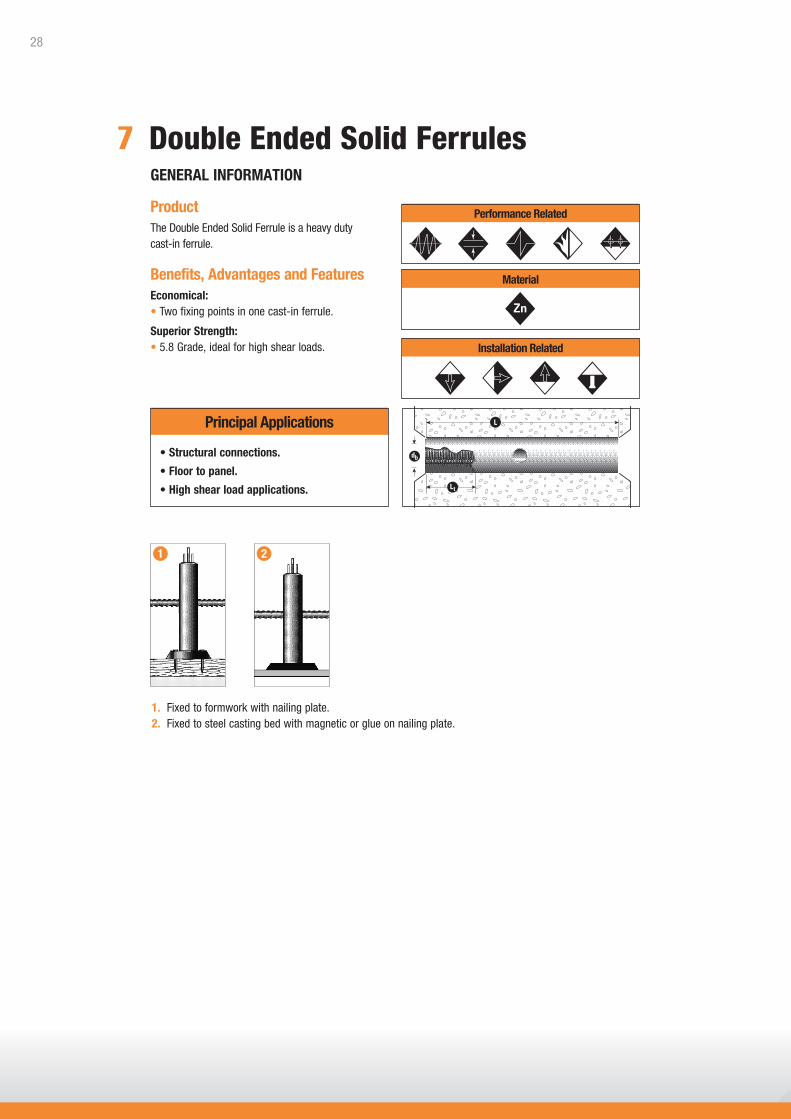
ProductThe Double Ended Solid Ferrule is a heavy duty cast-in ferrule.
Benefits, Advantages and FeaturesEconomical:• Two fixing points in one cast-in ferrule.
Superior Strength:• 5.8 Grade, ideal for high shear loads.
GENERAL INFORMATION
1. Fixed to formwork with nailing plate.2. Fixed to steel casting bed with magnetic or glue on nailing plate.
1 2
PERFORMANCE RELATED MATERIAL INSTALLATION RELATEDPerformance Related
Principal Applications
Material
PERFORMANCE RELATED MATERIAL INSTALLATION RELATEDInstallation Related
• Structural connections.
• Floor to panel.
• High shear load applications.
7 Double Ended Solid Ferrules
28

* If minimum critical distances cannot be achieved, please use the simplified limit state design process to verify capacity.** Recommended tightening torques are based on the use of grade 4.6 bolts.Note: Confirm bolt capacity independently of tabulated information.
Double Ended Solid Ferrules
Installation and Working Load Limit Performance Details
ENGINEERING PROPERTIES
Ferrule Stress Area Carbon Steel size, db at cross hole, As Yield strength, UTS, (mm2) fy (MPa) fu (MPa)
M16 234 400 500 M20 234 400 500
DESCRIPTION AND PART NUMBERS
Ferrule Ferrule Effective Min Thread Cross hole Part No. size, db length, L depth, h length, Lt to suit Zn (mm) (mm) (mm)
M16 115 62 32 N12 FD16115S M16 140 75 32 N12 FD16140S M16 165 87 32 N12 FD16165S M20 115 62 38 N12 FD20115S M20 140 75 38 N12 FD20140S M20 165 87 38 N12 FD20165S M20 190 100 38 N12 FD20190S
Effective depth, h (mm). Read value from “Description and Part Numbers” table.
Installation Details Minimum Critical Distances* Working Load Limit (kN) Threaded Cross Bar Recommended Edge Anchor To Suit Panel Anchor Details Torque, Tr distance, ec spacing, ac thickness, (t) Size (Nm) (mm) (mm) (mm) 4.6 Grade 8.8 Grade 20 MPa 32 MPa 40 MPa
M16 x 115 N12 x 300 75 90 180 125 13.7 28.1 13.5 17.1 19.1 M16 x 140 N12 x 300 75 110 220 150 13.7 28.1 18.2 23.0 25.7 M16 x 165 N12 x 300 75 130 260 175 13.7 28.1 23.2 29.4 32.9 M20 x 115 N12 x 300 144 90 180 125 21.5 44.2 13.5 17.1 19.1 M20 x 140 N12 x 300 144 110 220 150 21.5 44.2 18.2 23.0 25.7 M20 x 165 N12 x 300 144 130 260 175 21.5 44.2 23.2 29.4 32.9 M20 x 190 N12 x 300 144 150 300 200 21.5 44.2 28.7 36.3 40.6
Tension, NaConcrete Strength, f’c
Shear, VasLimited by Bolt Capacity
29

Design shear action effect, V* (kN)
Desi
gn te
nsile
act
ion
effe
ct, N
* (k
N)
Notes:• Shear limited by 4.6 Grade bolt. • Tension limited by concrete cone capacity.• No edge or spacing effects.• f'c = 32 MPa
0 10 20 30 40
0
10
20
40
30
60
50
M20 x 115
M20 x 190
M20 x 140
M20 x 165
Table 1a - Indicative combined loading – interaction diagram
Table 1b - Absolute minimum edge distance and anchor spacing values, em and am (mm)
Step 1c - Calculate anchor effective depth, h (mm)
Effective depth, h (mm)
Read value from “Description and Part Numbers” table on previous page.
Anchor size determined, absolute minima compliance achieved, effective depth (h) calculated.Checkpoint 1
Ferrule Length 115mm 140mm 165mm 190mm
em, am 40 50 60 70
Strength Limit State Design / Double Ended Solid Ferrules
Select anchor to be evaluatedSTEP 1
30

STEP 2 Verify concrete tensile capacity - per anchor
Table 2b - Concrete compressive strength effect, tension, Xnc
Table 2a - Reduced characteristic ultimate concrete tensile capacity, ØNuc (kN), Øc = 0.6, f’c = 32 MPa
Ferrule Length, L (mm) Ferrule Size, db Effective Depth, h (mm) ØNuc (kN)
115 M16 62 27.2 140 M16 75 36.3 165 M16 87 41.4 115 M20 62 27.2 140 M20 75 36.3 165 M20 87 41.4 190 M20 100 55.8
Anchor spacing, a (mm) 40 50 60 70 80 100 125 150 175 200 225 250 300 Ferrule length Effective depth L (mm) h (mm) 115 62 0.61 0.63 0.66 0.69 0.72 0.77 0.84 0.90 0.97 1.00 140 75 0.59 0.61 0.63 0.66 0.68 0.72 0.78 0.83 0.89 0.94 1.00 165 87 0.60 0.61 0.63 0.65 0.69 0.74 0.79 0.84 0.88 0.93 0.98 1.00 190 100 0.60 0.62 0.63 0.67 0.71 0.75 0.79 0.83 0.88 0.92 1.00
Anchor spacing, a (mm) 40 50 60 70 80 100 125 150 175 200 225 250 300 Ferrule length Effective depth L (mm) h (mm) 115 62 0.22 0.27 0.32 0.38 0.43 0.54 0.67 0.81 0.94 1.00 140 75 0.18 0.22 0.27 0.31 0.36 0.44 0.56 0.67 0.78 0.89 1.00 165 87 0.15 0.19 0.23 0.27 0.31 0.38 0.48 0.57 0.67 0.77 0.86 0.96 1.00 190 100 0.13 0.17 0.20 0.23 0.27 0.33 0.42 0.50 0.58 0.67 0.75 0.83 1.00
Table 2d - Anchor spacing effect, end of a row, tension, Xnae
Table 2e - Anchor spacing effect, internal to a row, tension, Xnai
Table 2c - Edge distance effect, tension, Xne
Edge distance, e (mm) 40 50 60 70 80 100 125 150 Ferrule length Effective depth L (mm) h (mm) 115 62 0.60 0.68 0.75 0.83 0.90 1.00 140 75 0.55 0.61 0.67 0.74 0.80 0.92 1.00 165 87 0.57 0.62 0.68 0.73 0.84 0.97 1.00 190 100 0.58 0.63 0.67 0.77 0.88 1.00
Strength Limit State Design / Double Ended Solid Ferrules
Design reduced ultimate concrete tensile capacity, ØNurc
ØNurc = ØNuc * Xnc * Xne * ( Xnae or Xnai )
Checkpoint 2
f’c (MPa) 15 20 25 32 40 50
Xnc 0.68 0.79 0.88 1.00 1.12 1.25
31

Table 3a - Reduced characteristic ultimate steel tensile capacity, ØNus (kN), Øn = 0.8
Step 3b - Reduced characteristic ultimate bolt steel tensile capacity, ØNtf (kN)
Establish the reduced characteristic ultimate bolt steel tensile capacity, ØNtf from literature supplied by the specified bolt manufacturer. For nominal expected capacities of bolts manufactured to ISO standards, refer to page 10.
STEP 3 Verify anchor tensile capacity - per anchor
Checkpoint 3 Design reduced ultimate tensile capacity, ØNur
ØNur = minimum of ØNurc, ØNus, ØNtf
Check N* / ØNur ≤ 1,
if not satisfied return to step 1
Table 4a - Reduced characteristic ultimate concrete edge shear capacity, ØVuc (kN), Øq = 0.6, f’c = 32 MPa
Ferrule Length, L (mm) 115 140 165 190
Edge distance, e (mm) 30 3.5 3.6 3.7 3.8 35 4.5 4.6 4.7 4.8 40 5.4 5.6 5.7 5.9 50 7.6 7.8 8.0 8.2 60 10.0 10.2 10.5 10.8 80 15.4 15.7 16.2 16.7 100 21.5 22.0 22.7 23.3 125 30.0 30.7 31.7 32.5 150 39.5 40.4 41.6 42.8 200 60.8 62.2 64.1 65.9 300 114.3 117.7 121.0 400 181.2 186.3 500 260.4
STEP 4 Verify concrete shear capacity - per anchor
Strength Limit State Design / Double Ended Solid Ferrules
Ferrule Size M16 M20
ØNus 93.6kN 93.6kN
32

Table 4b - Concrete compressive strength effect, concrete edge shear, Xvc
Load direction effect,conc. edge shear, Xvd
Table 4c - Load direction effect, concrete edge shear, Xvd
Angle, α° 0 10 20 30 40 50 60 70 80 90 - 180
Xvd 1.00 1.04 1.16 1.32 1.50 1.66 1.80 1.91 1.98 2.00
V*
α
Table 4d - Anchor spacing effect, concrete edge shear, Xva
Note: For single anchor designs, Xva = 1.0
Edge distance, 30 35 40 50 60 70 100 200 300 400 500 600 e (mm)
Anchor spacing, a (mm) 30 0.70 0.67 0.65 0.62 0.60 0.59 0.56 0.53 35 0.73 0.70 0.68 0.64 0.62 0.60 0.57 0.54 0.52 40 0.77 0.73 0.70 0.66 0.63 0.61 0.58 0.54 0.53 50 0.83 0.79 0.75 0.70 0.67 0.64 0.60 0.55 0.53 0.53 60 0.90 0.84 0.80 0.74 0.70 0.67 0.62 0.56 0.54 0.53 0.52 75 1.00 0.93 0.88 0.80 0.75 0.71 0.65 0.58 0.55 0.54 0.53 0.53 100 1.00 1.00 0.90 0.83 0.79 0.70 0.60 0.57 0.55 0.54 0.53 125 1.00 0.92 0.86 0.75 0.63 0.58 0.56 0.55 0.54 150 1.00 0.93 0.80 0.65 0.60 0.58 0.56 0.55 200 1.00 0.90 0.70 0.63 0.60 0.58 0.57 300 1.00 0.80 0.70 0.65 0.62 0.60 450 0.95 0.80 0.73 0.68 0.65 600 1.00 0.90 0.80 0.74 0.70 750 1.00 0.88 0.80 0.75 1000 1.00 0.90 0.83 1250 1.00 0.92 1500 1.00
Strength Limit State Design / Double Ended Solid Ferrules
Anchor spacing / 0.20 0.40 0.60 0.80 1.00 1.20 1.40 1.60 1.80 2.00 2.25 2.50
Edge distance, a / e
Number of anchors, n 2 1.00 1.00 1.00 1.00 1.00 1.00 1.00 1.00 1.00 1.00 1.00 1.00 3 0.72 0.76 0.80 0.83 0.86 0.88 0.91 0.93 0.95 0.96 0.98 1.00 4 0.57 0.64 0.69 0.74 0.79 0.82 0.86 0.89 0.92 0.94 0.97 1.00 5 0.49 0.57 0.63 0.69 0.74 0.79 0.83 0.87 0.90 0.93 0.97 1.00 6 0.43 0.52 0.59 0.66 0.71 0.77 0.81 0.85 0.89 0.93 0.96 1.00 7 0.39 0.48 0.56 0.63 0.69 0.75 0.80 0.84 0.88 0.92 0.96 1.00 8 0.36 0.46 0.54 0.61 0.68 0.74 0.79 0.84 0.88 0.92 0.96 1.00 9 0.34 0.44 0.52 0.60 0.67 0.73 0.78 0.83 0.87 0.91 0.96 1.00 10 0.32 0.42 0.51 0.59 0.66 0.72 0.77 0.82 0.87 0.91 0.96 1.00 15 0.26 0.37 0.47 0.55 0.63 0.70 0.76 0.81 0.86 0.90 0.95 1.00 20 0.23 0.35 0.45 0.54 0.61 0.68 0.75 0.80 0.85 0.90 0.95 1.00
Table 4e - Multiple anchors effect, concrete edge shear, Xvn Note: For single anchor designs, Xvn = 1.0
STEP 4continued
Design reduced ultimate concrete edge shear capacity, ØVurc
ØVurc = ØVuc * Xvc * Xvd * Xva * Xvn
Checkpoint 4
f’c (MPa) 15 20 25 32 40 50
Xvc 0.68 0.79 0.88 1.00 1.12 1.25
33

Strength Limit State Design / Double Ended Solid Ferrules
Check
N*/ØNur + V*/ØVur ≤ 1.2,
if not satisfied return to step 1
Checkpoint 6
STEP 6 Combined loading and specification
HOW TO SPECIFYReid™ Double Ended Ferrule, (Ferrule Size x Length) ((Part Number)) with a (Bolt Grade) bolt.
EXAMPLEReid™ Double Ended Ferrule, M16 x 140 (FD16140S) with a Grade 4.6 bolt.
Please refer to Reid™ Product Guides for the range of accessories (nailing plates, antennae caps, chairing solutions, etc) that are available.
Table 5a - Reduced characteristic ultimate shear capacity, ØVus (kN)
Verify anchor shear capacity - per anchorSTEP 5
Ferrule Size M16 M20
ØNus (Zinc) 83.0* 83.0*
Checkpoint 5 Design reduced ultimate shear capacity, ØVur
ØVur = minimum of ØVurc, ØVus, ØVsf
Check V* / ØVur ≤ 1,
if not satisfied return to step 1
* This value requires minimum f’c = 32MPa.
34

8 Tube Ferrules
ProductThe Tube Ferrule is a light duty cast-in ferrule.
Benefits, Advantages and FeaturesEconomic Design:• Simple and cost effective solution for light duty
fixing points.
• Economical stainless steel solution
GENERAL INFORMATION
PERFORMANCE RELATED MATERIAL INSTALLATION RELATEDPerformance Related
Material
PERFORMANCE RELATED MATERIAL INSTALLATION RELATEDInstallation Related
db
Lt
L
1. Fixed with nailing plate or bolted through formwork.2. Fixed to steel formwork with magnetic or glue on nailing plate.
1 2
Principal Applications
• Formwork support.
• Suspended services.
• Light to medium duty fixing points.
35
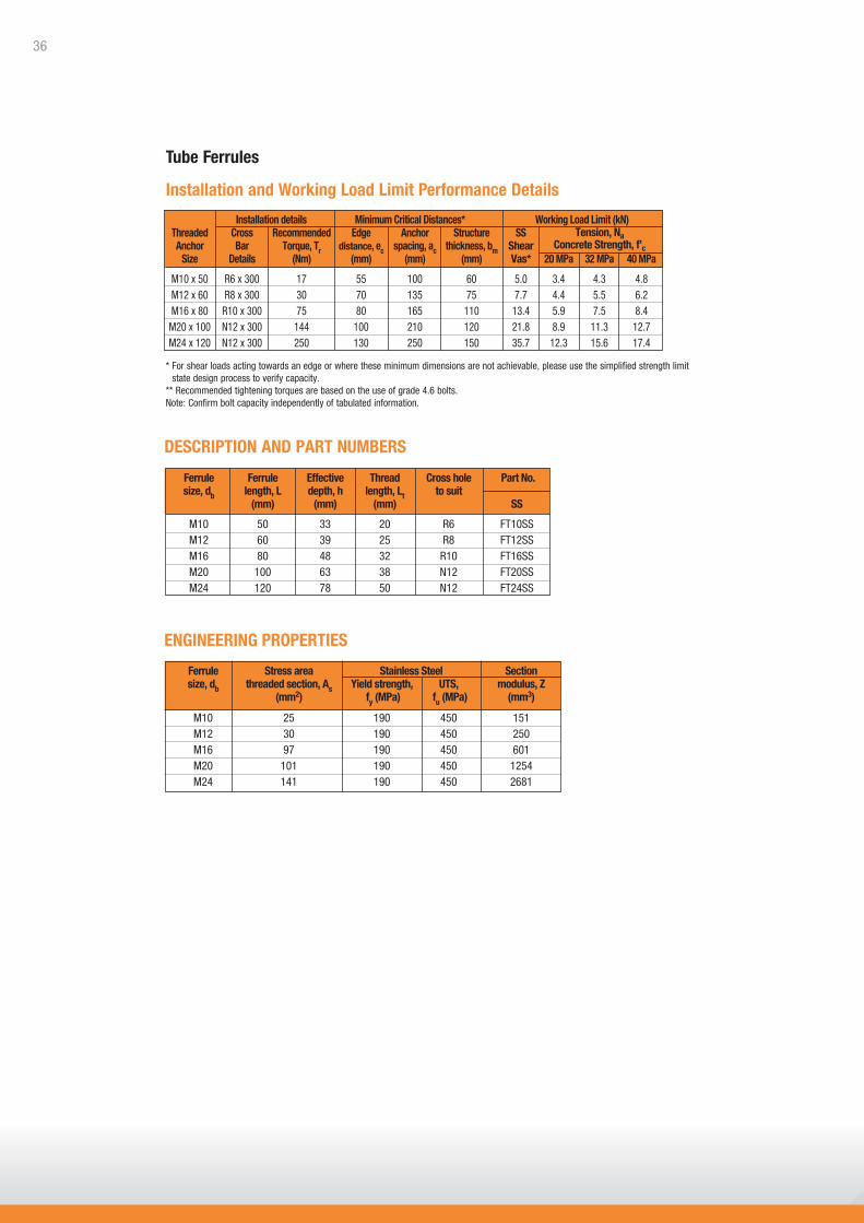
* For shear loads acting towards an edge or where these minimum dimensions are not achievable, please use the simplified strength limit state design process to verify capacity.
** Recommended tightening torques are based on the use of grade 4.6 bolts.Note: Confirm bolt capacity independently of tabulated information.
Tube Ferrules
Installation and Working Load Limit Performance Details
ENGINEERING PROPERTIES
DESCRIPTION AND PART NUMBERS
Installation details Minimum Critical Distances* Working Load Limit (kN) Threaded Cross Recommended Edge Anchor Structure SS Anchor Bar Torque, Tr distance, ec spacing, ac thickness, bm Shear Size Details (Nm) (mm) (mm) (mm) Vas* 20 MPa 32 MPa 40 MPa
M10 x 50 R6 x 300 17 55 100 60 5.0 3.4 4.3 4.8 M12 x 60 R8 x 300 30 70 135 75 7.7 4.4 5.5 6.2 M16 x 80 R10 x 300 75 80 165 110 13.4 5.9 7.5 8.4 M20 x 100 N12 x 300 144 100 210 120 21.8 8.9 11.3 12.7 M24 x 120 N12 x 300 250 130 250 150 35.7 12.3 15.6 17.4
Tension, NaConcrete Strength, f’c
Ferrule Ferrule Effective Thread Cross hole Part No. size, db length, L depth, h length, Lt to suit (mm) (mm) (mm) SS
M10 50 33 20 R6 FT10SS M12 60 39 25 R8 FT12SS M16 80 48 32 R10 FT16SS M20 100 63 38 N12 FT20SS M24 120 78 50 N12 FT24SS
Ferrule Stress area Stainless Steel Section size, db threaded section, As Yield strength, UTS, modulus, Z (mm2) fy (MPa) fu (MPa) (mm3)
M10 25 190 450 151 M12 30 190 450 250 M16 97 190 450 601 M20 101 190 450 1254 M24 141 190 450 2681
36

Design shear action effect, V* (kN)
Desi
gn te
nsile
act
ion
effe
ct, N
* (k
N)
Notes:• Shear limited by ferrule capacity.• Tension limited by concrete cone capacity.• No edge or spacing effects.• f'c = 32 MPa
0 5 10 15 20
0
10
20
5
15
M10
M12
M16
M20
Table 1a - Indicative combined loading – interaction diagram
Table 1b - Absolute minimum edge distance and anchor spacing values, em and am (mm)
Step 1c - Calculate anchor effective depth, h (mm)
Effective depth, h (mm)
Read value from “Description and Part Numbers” table on previous page.
Anchor size determined, absolute minima compliance achieved, effective depth (h) calculated.Checkpoint 1
Ferrule Size M10 M12 M16 M20 M24
em, am 30 35 40 50 65
Strength Limit State Design / Tube Ferrules
Select anchor to be evaluatedSTEP 1
37

STEP 2 Verify concrete tensile capacity - per anchor
Table 2b - Concrete compressive strength effect, tension, Xnc
f’c (MPa) 15 20 25 32 40 50
Xnc 0.68 0.79 0.88 1.00 1.12 1.25
Table 2a - Reduced characteristic ultimate concrete tensile capacity, ØNuc (kN), Øc = 0.6, f’c = 32 MPa
Ferrule Length, L (mm) Ferrule Size, db Effective Depth, h (mm) ØNuc (kN)
50 M10 33 7.7 60 M12 39 9.9 80 M16 48 13.5 100 M20 63 20.4 120 M24 78 28.1
Anchor spacing, a (mm) 30 40 50 60 70 85 100 125 150 200 250 Ferrule Effective depth Size h (mm) M10 35 0.64 0.69 0.74 0.79 0.83 0.90 1.00 M12 45 0.65 0.69 0.72 0.76 0.81 0.87 1.00 M16 55 0.62 0.65 0.68 0.71 0.76 0.80 0.88 1.00 M20 70 0.62 0.64 0.67 0.70 0.74 0.80 0.86 1.00 M24 85 0.62 0.64 0.67 0.70 0.75 0.79 0.89 1.00
Table 2d - Anchor spacing effect, end of a row, tension, Xnae
Anchor spacing, a (mm) 30 40 50 60 70 85 100 125 150 200 250 Ferrule Effective depth Size h (mm) M10 35 0.29 0.38 0.48 0.57 0.67 0.81 0.95 1.00 M12 45 0.30 0.37 0.44 0.52 0.63 0.74 0.93 1.00 M16 55 0.24 0.30 0.36 0.42 0.52 0.61 0.76 0.91 1.00 M20 70 0.24 0.29 0.33 0.40 0.48 0.60 0.71 0.95 1.00 M24 85 0.24 0.27 0.33 0.39 0.49 0.59 0.78 1.00
Table 2e - Anchor spacing effect, internal to a row, tension, Xnai
Table 2c - Edge distance effect, tension, Xne
Edge distance effect, e (mm) 25 30 35 40 50 65 70 80 100 130 Ferrule size M10 0.62 0.68 0.75 0.82 0.96 1.00 M12 0.56 0.60 0.65 0.70 0.80 0.97 1.00 M16 0 0.55 0.59 0.63 0.71 0.84 0.88 1.00 M20 0 0.53 0.56 0.62 0.72 0.75 0.82 1.00 M24 0 0.52 0.57 0.64 0.67 0.72 0.83 1.00
Strength Limit State Design / Tube Ferrules
Design reduced ultimate concrete tensile capacity, ØNurc
ØNurc = ØNuc * Xnc * Xne * ( Xnae or Xnai )
Checkpoint 2
38
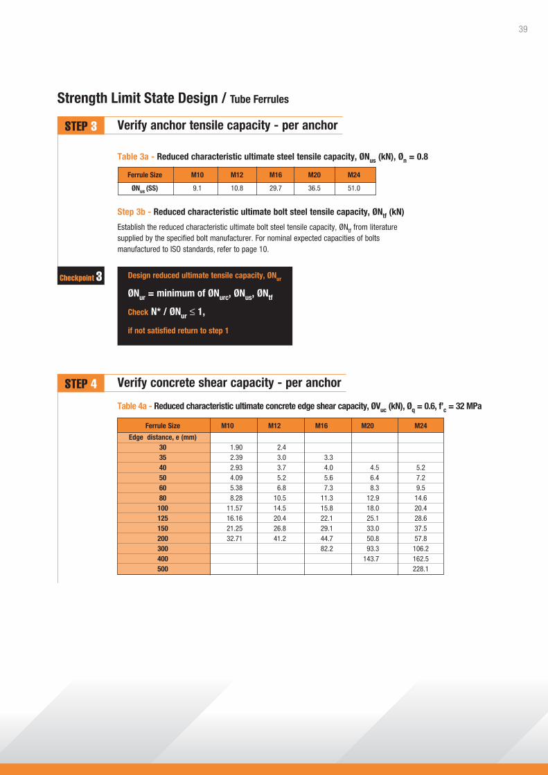
Table 3a - Reduced characteristic ultimate steel tensile capacity, ØNus (kN), Øn = 0.8
Step 3b - Reduced characteristic ultimate bolt steel tensile capacity, ØNtf (kN)
Establish the reduced characteristic ultimate bolt steel tensile capacity, ØNtf from literature supplied by the specified bolt manufacturer. For nominal expected capacities of bolts manufactured to ISO standards, refer to page 10.
STEP 3 Verify anchor tensile capacity - per anchor
Checkpoint 3 Design reduced ultimate tensile capacity, ØNur
ØNur = minimum of ØNurc, ØNus, ØNtf
Check N* / ØNur ≤ 1,
if not satisfied return to step 1
Table 4a - Reduced characteristic ultimate concrete edge shear capacity, ØVuc (kN), Øq = 0.6, f’c = 32 MPa
Ferrule Size M10 M12 M16 M20 M24
Edge distance, e (mm) 30 1.90 2.4 35 2.39 3.0 3.3 40 2.93 3.7 4.0 4.5 5.2 50 4.09 5.2 5.6 6.4 7.2 60 5.38 6.8 7.3 8.3 9.5 80 8.28 10.5 11.3 12.9 14.6 100 11.57 14.5 15.8 18.0 20.4 125 16.16 20.4 22.1 25.1 28.6 150 21.25 26.8 29.1 33.0 37.5 200 32.71 41.2 44.7 50.8 57.8 300 82.2 93.3 106.2 400 143.7 162.5 500 228.1
STEP 4 Verify concrete shear capacity - per anchor
Strength Limit State Design / Tube Ferrules
Ferrule Size M10 M12 M16 M20 M24
ØNus (SS) 9.1 10.8 29.7 36.5 51.0
39
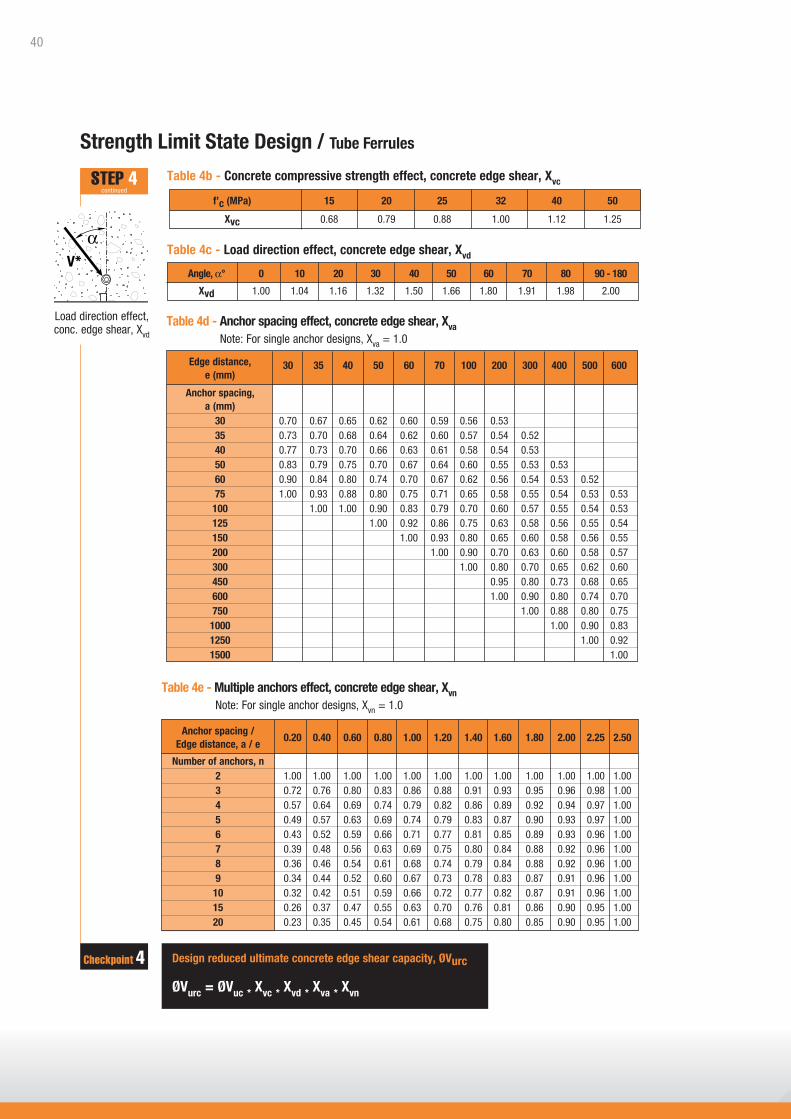
Table 4b - Concrete compressive strength effect, concrete edge shear, Xvc
Load direction effect,conc. edge shear, Xvd
Table 4c - Load direction effect, concrete edge shear, Xvd
Angle, α° 0 10 20 30 40 50 60 70 80 90 - 180
Xvd 1.00 1.04 1.16 1.32 1.50 1.66 1.80 1.91 1.98 2.00
V*
α
Table 4d - Anchor spacing effect, concrete edge shear, Xva
Note: For single anchor designs, Xva = 1.0
Edge distance, 30 35 40 50 60 70 100 200 300 400 500 600 e (mm)
Anchor spacing, a (mm) 30 0.70 0.67 0.65 0.62 0.60 0.59 0.56 0.53 35 0.73 0.70 0.68 0.64 0.62 0.60 0.57 0.54 0.52 40 0.77 0.73 0.70 0.66 0.63 0.61 0.58 0.54 0.53 50 0.83 0.79 0.75 0.70 0.67 0.64 0.60 0.55 0.53 0.53 60 0.90 0.84 0.80 0.74 0.70 0.67 0.62 0.56 0.54 0.53 0.52 75 1.00 0.93 0.88 0.80 0.75 0.71 0.65 0.58 0.55 0.54 0.53 0.53 100 1.00 1.00 0.90 0.83 0.79 0.70 0.60 0.57 0.55 0.54 0.53 125 1.00 0.92 0.86 0.75 0.63 0.58 0.56 0.55 0.54 150 1.00 0.93 0.80 0.65 0.60 0.58 0.56 0.55 200 1.00 0.90 0.70 0.63 0.60 0.58 0.57 300 1.00 0.80 0.70 0.65 0.62 0.60 450 0.95 0.80 0.73 0.68 0.65 600 1.00 0.90 0.80 0.74 0.70 750 1.00 0.88 0.80 0.75 1000 1.00 0.90 0.83 1250 1.00 0.92 1500 1.00
Strength Limit State Design / Tube Ferrules
Anchor spacing / 0.20 0.40 0.60 0.80 1.00 1.20 1.40 1.60 1.80 2.00 2.25 2.50
Edge distance, a / e
Number of anchors, n 2 1.00 1.00 1.00 1.00 1.00 1.00 1.00 1.00 1.00 1.00 1.00 1.00 3 0.72 0.76 0.80 0.83 0.86 0.88 0.91 0.93 0.95 0.96 0.98 1.00 4 0.57 0.64 0.69 0.74 0.79 0.82 0.86 0.89 0.92 0.94 0.97 1.00 5 0.49 0.57 0.63 0.69 0.74 0.79 0.83 0.87 0.90 0.93 0.97 1.00 6 0.43 0.52 0.59 0.66 0.71 0.77 0.81 0.85 0.89 0.93 0.96 1.00 7 0.39 0.48 0.56 0.63 0.69 0.75 0.80 0.84 0.88 0.92 0.96 1.00 8 0.36 0.46 0.54 0.61 0.68 0.74 0.79 0.84 0.88 0.92 0.96 1.00 9 0.34 0.44 0.52 0.60 0.67 0.73 0.78 0.83 0.87 0.91 0.96 1.00 10 0.32 0.42 0.51 0.59 0.66 0.72 0.77 0.82 0.87 0.91 0.96 1.00 15 0.26 0.37 0.47 0.55 0.63 0.70 0.76 0.81 0.86 0.90 0.95 1.00 20 0.23 0.35 0.45 0.54 0.61 0.68 0.75 0.80 0.85 0.90 0.95 1.00
Table 4e - Multiple anchors effect, concrete edge shear, Xvn Note: For single anchor designs, Xvn = 1.0
STEP 4continued
Design reduced ultimate concrete edge shear capacity, ØVurc
ØVurc = ØVuc * Xvc * Xvd * Xva * Xvn
Checkpoint 4
f’c (MPa) 15 20 25 32 40 50
Xvc 0.68 0.79 0.88 1.00 1.12 1.25
40

Strength Limit State Design / Tube Ferrules
Check
N*/ØNur + V*/ØVur ≤ 1.2,
if not satisfied return to step 1
Checkpoint 6
STEP 6 Combined loading and specification
HOW TO SPECIFYReid™ Tube Ferrule, (Ferrule Size x Length) ((Part Number)) with a (Bolt Grade) bolt.______ cross bar required
EXAMPLEReid™ Tube Ferrule, M16 x 70 (FT16) with a Grade 4.6 bolt.R10 x 300mm cross bar required
Table 5a - Reduced characteristic ultimate shear capacity, ØVus (kN), Øv = 0.8
Verify anchor shear capacity - per anchorSTEP 5
Ferrule Size M10 M12 M16 M20 M24
ØNus (Zinc) 5.0 5.9 16.4 20.1
ØNus (SS) 5.6 6.7 18.4 22.6 31.6
Checkpoint 5 Design reduced ultimate shear capacity, ØVur
ØVur = minimum of ØVurc, ØVus, ØVsf
Check V* / ØVur ≤ 1,
if not satisfied return to step 1
41

Project
Design
Location
Project ID Date
Design by Checked
Notes
N* & V* are the per anchor load cases.Check both external and internal anchors for suitability.
Tensile design action effect N* kN
Shear design action effect V* kN
Fixture thickness t mm
Concrete compressive strength f’c MPa
Anchor spacing a mm
Edge distance e mm
No. of anchors in row parallel to edge n
Direction of shear load degs.
Sketch
Select anchor to be evaluatedSTEP 1Table 1a Interaction Diagram
Find intersection of N* and V* values.
Select anchor size.
Table 1b Absolute minima, am & em
Check for compliance with absolute minima
Step 1c Calculate effective depth, h
Anchor size selected?
Comply with absolute minima?
Effective depth, h calculated?
Checkpoint 1
Notes for this application
Anchor Type
Tick
Tick
Tick
Tick
9 Anchoring Design Worksheet
42
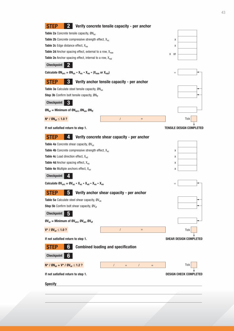
Specify
Verify concrete tensile capacity - per anchorSTEP 2
STEP 3
STEP 4
STEP 5
STEP 6
Table 2a Concrete tensile capacity, ØNuc
Table 2b Concrete compressive strength effect, Xnc x
Table 2c Edge distance effect, Xne x
Table 2d Anchor spacing effect, external to a row, Xnae x orTable 2e Anchor spacing effect, internal to a row, Xnai
Calculate ØNurc = ØNuc * Xnc * Xne * (Xnae or Xnai) =
Checkpoint 2
Checkpoint 3
Checkpoint 4
Checkpoint 5
Checkpoint 6
Verify anchor tensile capacity - per anchor
Table 3a Calculate steel tensile capacity, ØNus
Step 3b Confirm bolt tensile capacity, ØNtf
ØNur = Minimum of ØNurc, ØNus, ØNtf
N* / ØNur ≤ 1.0 ? /
If not satisfied return to step 1. TENSILE DESIGN COMPLETED
Verify concrete shear capacity - per anchor
Table 4a Concrete shear capacity, ØVuc
Table 4b Concrete compressive strength effect, Xvc x
Table 4c Load direction effect, Xvd x
Table 4d Anchor spacing effect, Xva x
Table 4e Multiple anchors effect, Xvn x
Calculate ØVurc = ØVuc * Xvc * Xvd * Xva * Xvn =
Verify anchor shear capacity - per anchor
Combined loading and specification
Table 5a Calculate steel shear capacity, ØVus
Step 5b Confirm bolt shear capacity, ØVsf
ØVur = Minimum of ØVurc, ØVus, ØVsf
V* / ØVur ≤ 1.0 ? Tick
Tick
If not satisfied return to step 1. SHEAR DESIGN COMPLETED
N* / ØNur + V* / ØVur ≤ 1.2 ? / + =
=
/ =
/
If not satisfied return to step 1. DESIGN CHECK COMPLETED
Tick
43

Solutions for Structural Concrete
R E I N F O R C I N G • P R E C A S T • T I L T - U P
TM
Leading the Industry in Product InnovationReid™ has been providing solutions to the concrete construction sector for over 40 years and our knowledge of
the industry has enabled us to evolve into a company that is a leader in product innovation and service. Many of our products are developed and produced in our Australian manufacturing plants,
including our Round Bar Ferrules, proudly Australian made for over 15 years.
Leading the Industry in SafetyReid are ISO 9001 accredited and have a complete quality control system in place, including in-house testing
facilities, which has allowed us to maintain a long standing focus on quality and reliability, ensuring products carrying the Reid brand are the very best on the market.
Reid™ - partnering you and your business
ENGINEERING CONTACTS NSW/ACT: 0438 540 482 SA/TAS: 0409 672 943 QLD/NT: 0407 510 079 WA: (08) 9455 3622 VIC: 0419 164 066
Customer Service Centre
1300 780 250www.reid.com.au
ITW Construction Systems Australia Pty. Ltd. ABN 48 004 297 009 Trading as Reid™ ™Trademarks if ITW Construction Systems Australia Pty. Ltd. ™Ramset is a trademark of Cetram Pty. Ltd.
© Copyright 2010 REID17789MDG10/10. All information contained in this document is correct at time of printing but is subject to change without notice.