Embed Size (px)
Citation preview
SOLO, LSH & L1000Proximity Tag Systems
FIELD TESTGUIDE
2007.02.12
FIELD TEST GUIDE
CENTURION SYSTEMS has been manufacturing automatic gate systems since 1987, and is committed to providing reliable, cost effective solutions in the field of access automation.
CENTURION strives to give service and backup second to none. Our engineers are available to give sales support, installation training, and answers to technical or installation problems.
The equipment is installed worldwide and is available through a network of distributors.
CENTURION is an ISO 9001 registered company, continually looking at updating its products in line with world trends to ensure that its products will provide cus-tomer satisfaction.
Further information is available on our website www.centsys.co.za
Page 2
No part of this document may be copied, stored in a retrieval system or transmitted in any form or by any means electronic, mechanical, optical or photographic, without the express prior written consent of Centurion Systems (Pty) Ltd.
© CENTURION SYSTEMS (PTY) LTD 2005
Centurion Systems (Pty) Ltd. reserves the right to make changes to the products described in this manual without notice and without obligation of Centurion Systems (Pty) Ltd. to notify any persons of any such revisions or changes. Additionally, Centurion Systems (Pty) Ltd. makes no representations or warranties with respect to this manual.
Company ProfileCompany Profile
Introduction . . . . . . . . . . . . . . . . . . . . . . . . . . . . . . . . . . . . . . . . . . . . . . . . . . . . . . . . . . . . . . . . . . 4
Equipment required. . . . . . . . . . . . . . . . . . . . . . . . . . . . . . . . . . . . . . . . . . . . . . . . . . . . . . . . . . . . 5
Activating /enabling field test mode . . . . . . . . . . . . . . . . . . . . . . . . . . . . . . . . . . . . . . . . . . . . . . . 6
Recommended connection diagram . . . . . . . . . . . . . . . . . . . . . . . . . . . . . . . . . . . . . . . . . . . . . . 6
Power output test CHD+ . . . . . . . . . . . . . . . . . . . . . . . . . . . . . . . . . . . . . . . . . . . . . . . . . . . . . . . 7
LED’s and 7-segment tests . . . . . . . . . . . . . . . . . . . . . . . . . . . . . . . . . . . . . . . . . . . . . . . . . . . . . . 8
FRX input test . . . . . . . . . . . . . . . . . . . . . . . . . . . . . . . . . . . . . . . . . . . . . . . . . . . . . . . . . . . . . . . . 9
Relay and CHD output tests . . . . . . . . . . . . . . . . . . . . . . . . . . . . . . . . . . . . . . . . . . . . . . . . . . . . 10
DOOR SEN input . . . . . . . . . . . . . . . . . . . . . . . . . . . . . . . . . . . . . . . . . . . . . . . . . . . . . . . . . . . . 12
ALARM Output test . . . . . . . . . . . . . . . . . . . . . . . . . . . . . . . . . . . . . . . . . . . . . . . . . . . . . . . . . . . 12
Tag interface test . . . . . . . . . . . . . . . . . . . . . . . . . . . . . . . . . . . . . . . . . . . . . . . . . . . . . . . . . . . . . 13
Communication interface test
LSH only
Address DIP switches, RS485 terminating resistor and RS485 communications tests . . . . . . . 14
L1000 only
RS485 termination resistor, RS485 and take up head communications tests . . . . . . . . . . . . . . 14
. . . . . . . . . . . . . . . . . . . . . . . . . . . . . . . . . . . . . . 16
NOTES . . . . . . . . . . . . . . . . . . . . . . . . . . . . . . . . . . . . . . . . . . . . . . . . . . . . . . . . . . . . . . . . . . 17
Connection diagrams for communication test
Page 3
Table of ContentsTable of Contents
The SOLO, LSH and L1000 Proximity access control readers have built-in test firmware to allow an installer, or user, to field test the functional integrity of the various readers.
NB: It is important to note that all tests must follow the prescribed sequence as further tests rely on the success of the previous test.
NOTE: To ensure proper contact, screws must be tightened if measurements are taken on the screw tops.
Page 4
IntroductionIntroduction
Page 5
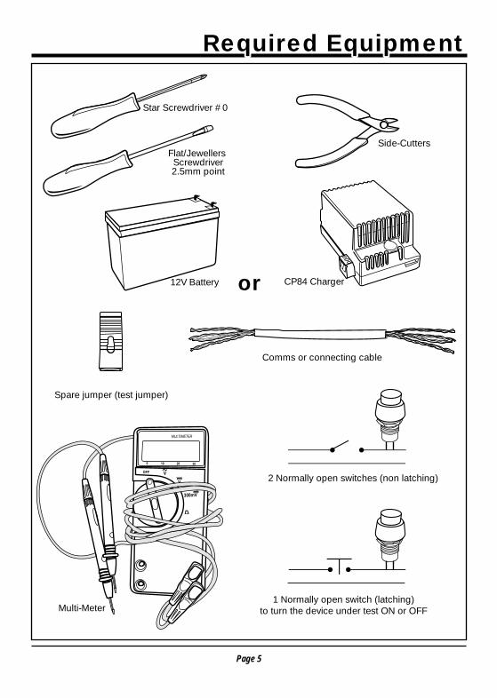
Star Screwdriver #0
Flat/Jewellers Screwdriver 2.5mm point
Required EquipmentRequired Equipment
oror
1 Normally open switch (latching) to turn the device under test ON or OFF
2 Normally open switches (non latching)
CP84 Charger
Comms or connecting cable
Side-Cutters
12V Battery
Multi-Meter
Spare jumper (test jumper)
Page 6
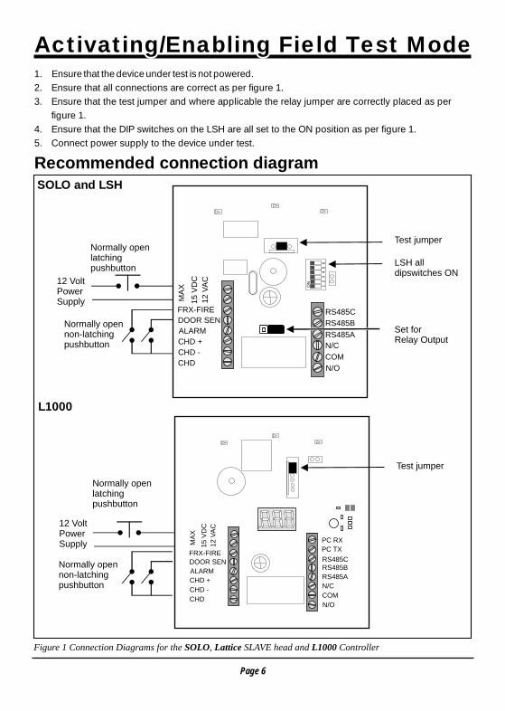
Activating/Enabling Field Test ModeActivating/Enabling Field Test Mode1. Ensure that the device under test is not powered.2. Ensure that all connections are correct as per figure 1.3. Ensure that the test jumper and where applicable the relay jumper are correctly placed as per
figure 1.4. Ensure that the DIP switches on the LSH are all set to the ON position as per figure 1.5. Connect power supply to the device under test.
Recommended connection diagram
Figure 1 Connection Diagrams for the SOLO, Lattice SLAVE head and L1000 Controller
12
ON
34
56
RS485C
RS485B
COM
N/OCHD
CHD -
CHD +
ALARM
DOOR SEN
FRX-FIRE
12
VA
C
MA
X
15
VD
C
CHD
CHD -
CHD +
ALARM
DOOR SEN
FRX-FIRE
12
VA
C
MA
X
15
VD
C
RS485C
PC TX
PC RX
RS485B
RS485A
N/C
COM
N/O
Test jumper
Test jumper
Normally openlatching pushbutton
Normally openlatching pushbutton
12 VoltPowerSupply
12 VoltPowerSupply
Normally opennon-latchingpushbutton
Normally opennon-latchingpushbutton
LSH all dipswitches ON
Set for Relay Output
SOLO and LSH
L1000
N/C
RS485A
Page 7
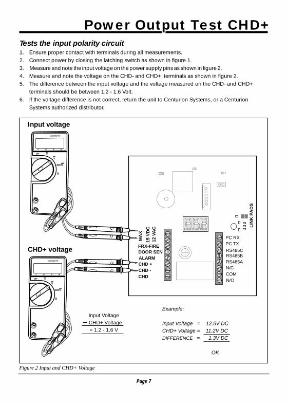
Power Output Test CHD+ Power Output Test CHD+ Tests the input polarity circuit1. Ensure proper contact with terminals during all measurements. 2. Connect power by closing the latching switch as shown in figure 1.3. Measure and note the input voltage on the power supply pins as shown in figure 2.4. Measure and note the voltage on the CHD- and CHD+ terminals as shown in figure 2.5. The difference between the input voltage and the voltage measured on the CHD- and CHD+
terminals should be between 1.2 - 1.6 Volt.6. If the voltage difference is not correct, return the unit to Centurion Systems, or a Centurion
Systems authorized distributor.
Figure 2 Input and CHD+ Voltage
Input voltage
CHD+ voltage
Input Voltage
CHD+ Voltage
= 1.2 - 1.6 V
CHD
CHD -
CHD +
ALARM
DOOR SEN
FRX-FIRE
12
VA
C
MA
X
15
VD
C
RS485C
PC TX
PC RX
RS485B
RS485A
N/C
COM
N/O
LIN
K P
AD
S
12.5
11.2
Example:
Input Voltage = 12.5V DC
CHD+ Voltage = 11.2V DC
DIFFERENCE = 1.3V DC
OK
Page 8
LED’s and 7 Segment IndicatorsLED’s and 7 Segment Indicators
Tests the LED’s and LED drive circuitry
SOLO and LSH1. Ensure that all 5 LED’s are ON.2. If correct move on to memory test.3. If the TOP RED LED flashes once every second then the input voltage is too low.4. If the TOP RED LED flashes 3 times every second then the input voltage is too high.5. If the input voltage is 12 volt and the above errors occur, then the unit must be returned to
Centurion Systems, or a Centurion Systems authorized distributor.
L1000Tests the 3-Digit, 7-Segment display the LED’s and their respective drive circuitry1. Ensure that the top 3 LED’s are ON.2. Ensure that each segment of the 3-digit 7-segment display is turned on sequentially.3. If correct move on to memory test.4. If the TOP RED LED flashes once every second then the input voltage is too low.5. If the input voltage is 12 volt and the above error occurs, then the unit must be returned to
Centurion Systems, or a Centurion Systems authorized distributor.
Tests the internal memory of the SOLO and LSH readers
SOLO and LSH1. Remove the test jumper refer to Figure 1.2. All 5 LED’s will begin to flash, this indicates that the memory is being tested. DO NOT REMOVE
POWER.3. Once the memory test is complete the BOTTOM GREEN and RED LED’s will flash.4. If the TOP ORANGE and RED LED’s flash continuously the memory test has failed. The unit must
be returned to Centurion Systems, or a Centurion Systems authorized distributor.
Memory TestMemory Test
NB: Ensure previous tests have been successfully performed.
NB: Ensure previous tests have been successfully performed.
Note: Removing power during the memory test will corrupt the memory contents. To preserve the memory contents DO NOT REMOVE POWER during the memory test.
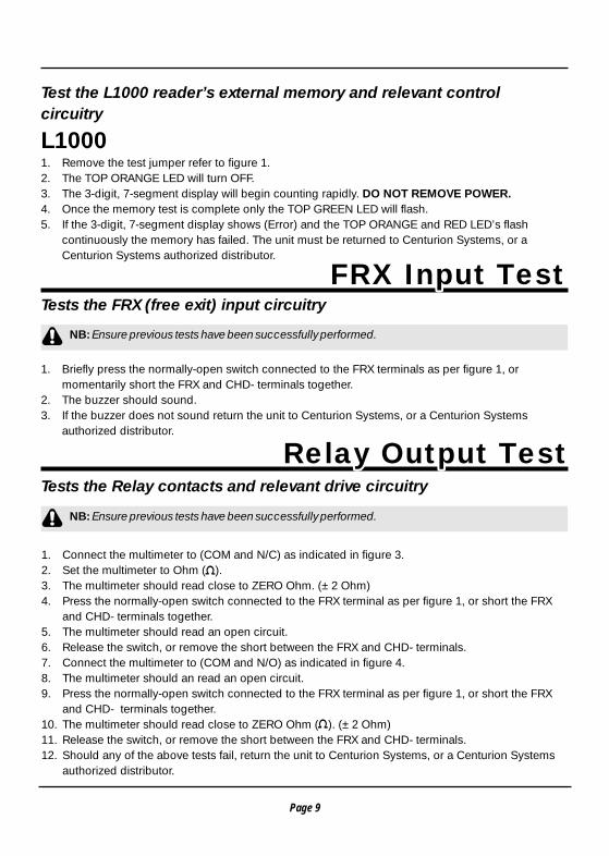
Test the L1000 reader’s external memory and relevant control circuitry
L10001. Remove the test jumper refer to figure 1.2. The TOP ORANGE LED will turn OFF.3. The 3-digit, 7-segment display will begin counting rapidly. DO NOT REMOVE POWER.4. Once the memory test is complete only the TOP GREEN LED will flash.5. If the 3-digit, 7-segment display shows (Error) and the TOP ORANGE and RED LED’s flash
continuously the memory has failed. The unit must be returned to Centurion Systems, or a Centurion Systems authorized distributor.
Tests the FRX (free exit) input circuitry
1. Briefly press the normally-open switch connected to the FRX terminals as per figure 1, or momentarily short the FRX and CHD- terminals together.
2. The buzzer should sound.3. If the buzzer does not sound return the unit to Centurion Systems, or a Centurion Systems
authorized distributor.
Tests the Relay contacts and relevant drive circuitry
FRX Input TestFRX Input Test
NB: Ensure previous tests have been successfully performed.
NB: Ensure previous tests have been successfully performed.
Memory Test
1. Connect the multimeter to (COM and N/C) as indicated in figure 3.2. Set the multimeter to Ohm ( ).3. The multimeter should read close to ZERO Ohm. (±2 Ohm)4. Press the normally-open switch connected to the FRX terminal as per figure 1, or short the FRX
and CHD- terminals together.5. The multimeter should read an open circuit.6. Release the switch, or remove the short between the FRX and CHD- terminals.7. Connect the multimeter to (COM and N/O) as indicated in figure 4. 8. The multimeter should an read an open circuit.9. Press the normally-open switch connected to the FRX terminal as per figure 1, or short the FRX
and CHD- terminals together.10. The multimeter should read close to ZERO Ohm ( ). (±2 Ohm)11. Release the switch, or remove the short between the FRX and CHD- terminals.12. Should any of the above tests fail, return the unit to Centurion Systems, or a Centurion Systems
authorized distributor.
Page 9
Relay Output TestRelay Output Test
Page 10
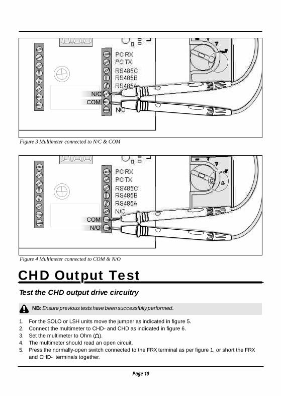
Figure 3 Multimeter connected to N/C & COM
Figure 4 Multimeter connected to COM & N/O
N/C
COM
ALARM
DOOR SEN
FRX-FIRE
12
VA
C
RS485C
PC TX
PC RX
RS485B
RS485A
N/O
LIN
K P
AD
S
N/C
COM
N/C
COM
ALARM
DOOR SEN
FRX-FIRE
12
VA
C
RS485C
PC TX
PC RX
RS485B
RS485A
LIN
K P
AD
S
COM
N/O
Relay Output Test
CHD Output TestCHD Output TestTest the CHD output drive circuitry
1. For the SOLO or LSH units move the jumper as indicated in figure 5.2. Connect the multimeter to CHD- and CHD as indicated in figure 6.3. Set the multimeter to Ohm ( ).4. The multimeter should read an open circuit.5. Press the normally-open switch connected to the FRX terminal as per figure 1, or short the FRX
and CHD- terminals together.
NB: Ensure previous tests have been successfully performed.
Page 11
Change jumper
position as indicated
ON
CHD
CHD -
CHD +
ALARM
DOOR SEN
FRX-FIRE
12
VA
C
MA
X
15
VD
C
N/C
COMCHD
CHD -
CHD +
ALARM
DOOR SEN
FRX-FIRE
12
VA
C
MA
X
15
VD
C
RS485C
PC TX
PC RX
RS485B
RS485A
CHD
CHD -
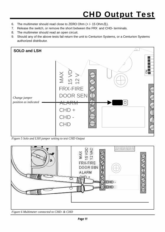
Figure 5 Solo and LSH jumper setting to test CHD Output
Figure 6 Multimeter connected to CHD- & CHD
CHD Output TestCHD Output Test
SOLO and LSH
6. The multimeter should read close to ZERO Ohm (+/- 15 Ohm ).7. Release the switch, or remove the short between the FRX and CHD- terminals.8. The multimeter should read an open circuit.9. Should any of the above tests fail return the unit to Centurion Systems, or a Centurion Systems
authorized distributor.
Page 12
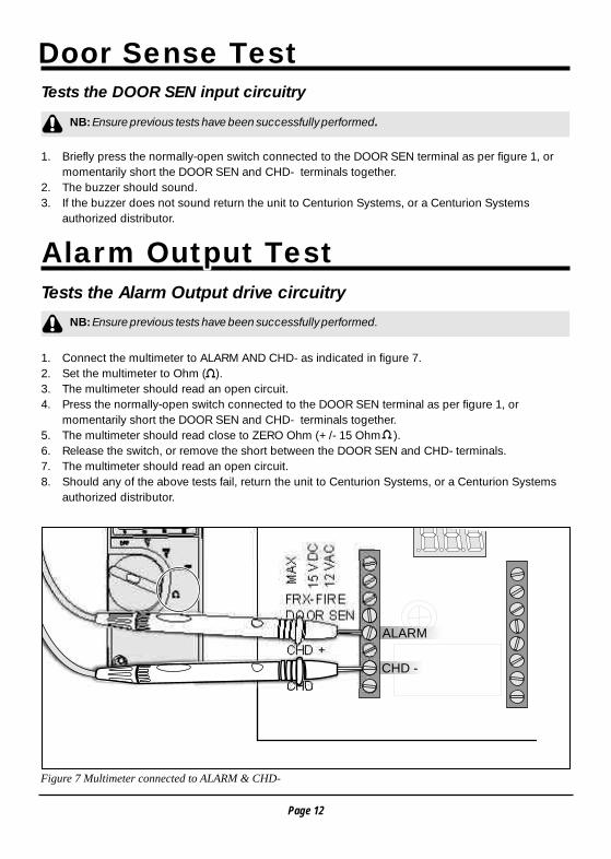
Figure 7 Multimeter connected to ALARM & CHD-
Door Sense TestDoor Sense Test
Alarm Output TestAlarm Output Test
Tests the DOOR SEN input circuitry
1. Briefly press the normally-open switch connected to the DOOR SEN terminal as per figure 1, or momentarily short the DOOR SEN and CHD- terminals together.
2. The buzzer should sound.3. If the buzzer does not sound return the unit to Centurion Systems, or a Centurion Systems
authorized distributor.
Tests the Alarm Output drive circuitry
1. Connect the multimeter to ALARM AND CHD- as indicated in figure 7.2. Set the multimeter to Ohm ( ).3. The multimeter should read an open circuit.4. Press the normally-open switch connected to the DOOR SEN terminal as per figure 1, or
momentarily short the DOOR SEN and CHD- terminals together.5. The multimeter should read close to ZERO Ohm (+/- 15 Ohm ).6. Release the switch, or remove the short between the DOOR SEN and CHD- terminals.7. The multimeter should read an open circuit.8. Should any of the above tests fail, return the unit to Centurion Systems, or a Centurion Systems
authorized distributor.
NB: Ensure previous tests have been successfully performed.
NB: Ensure previous tests have been successfully performed.
N/C
COMCHD
CHD -
CHD +
DOOR SEN
FRX-FIRE
12
VA
C
MA
X
15
VD
C
RS485C
PC TX
PC RX
RS485B
RS485A
CHD
CHD -
ALARM
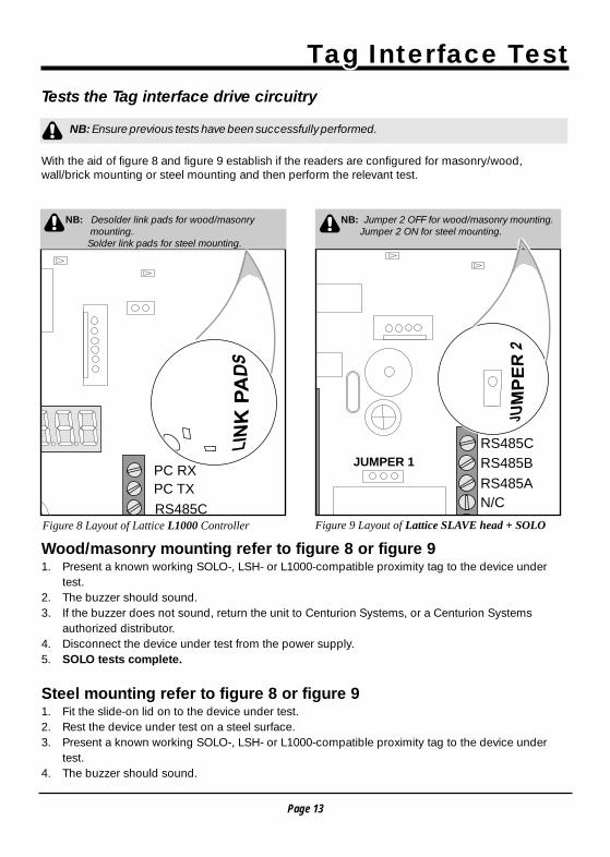
Tests the Tag interface drive circuitry
With the aid of figure 8 and figure 9 establish if the readers are configured for masonry/wood, wall/brick mounting or steel mounting and then perform the relevant test.
Wood/masonry mounting refer to figure 8 or figure 91. Present a known working SOLO-, LSH- or L1000-compatible proximity tag to the device under
test.2. The buzzer should sound.3. If the buzzer does not sound, return the unit to Centurion Systems, or a Centurion Systems
authorized distributor.4. Disconnect the device under test from the power supply.5. SOLO tests complete.
Steel mounting refer to figure 8 or figure 91. Fit the slide-on lid on to the device under test.2. Rest the device under test on a steel surface. 3. Present a known working SOLO-, LSH- or L1000-compatible proximity tag to the device under
test.4. The buzzer should sound.
Page 13
RS485C
PC TX
PC RX
LIN
K P
AD
S
RS485C
12
ON
34
56
JU
MP
ER
2
JUMPER 1 RS485B
RS485A
N/C
NB: Desolder link pads for wood/masonry mounting. Solder link pads for steel mounting.
NB: Jumper 2 OFF for wood/masonry mounting. Jumper 2 ON for steel mounting.
Figure 8 Layout of Lattice L1000 Controller Figure 9 Layout of Lattice SLAVE head + SOLO
Tag Interface TestTag Interface Test
NB: Ensure previous tests have been successfully performed.
Tests the Tag interface drive circuitry
With the aid of figure 8 and figure 9 establish if the readers are configured for masonry/wood, wall/brick mounting or steel mounting and then perform the relevant test.
Wood/masonry mounting refer to figure 8 or figure 91. Present a known working SOLO-, LSH- or L1000-compatible proximity tag to the device under
test.2. The buzzer should sound.3. If the buzzer does not sound, return the unit to Centurion Systems, or a Centurion Systems
authorized distributor.4. Disconnect the device under test from the power supply.5. SOLO tests complete.
Steel mounting refer to figure 8 or figure 91. Fit the slide-on lid on to the device under test.2. Rest the device under test on a steel surface. 3. Present a known working SOLO-, LSH- or L1000-compatible proximity tag to the device under
test.4. The buzzer should sound.
NB: Jumper 2 OFF for wood/masonry mounting. Jumper 2 ON for steel mounting.
Tests the Tag interface drive circuitry
With the aid of figure 8 and figure 9 establish if the readers are configured for masonry/wood, wall/brick mounting or steel mounting and then perform the relevant test.
Wood/masonry mounting refer to figure 8 or figure 91. Present a known working SOLO-, LSH- or L1000-compatible proximity tag to the device under
test.2. The buzzer should sound.3. If the buzzer does not sound, return the unit to Centurion Systems, or a Centurion Systems
authorized distributor.4. Disconnect the device under test from the power supply.5. SOLO tests complete.
Steel mounting refer to figure 8 or figure 91. Fit the slide-on lid on to the device under test.2. Rest the device under test on a steel surface. 3. Present a known working SOLO-, LSH- or L1000-compatible proximity tag to the device under
test.4. The buzzer should sound.
NB: Desolder link pads for wood/masonry mounting. Solder link pads for steel mounting.
Page 14
Tag Interface Test5. If the buzzer does not sound, return the unit to Centurion Systems, or a Centurion Systems
authorized distributor.6. Disconnect the device under test from the power supply.7. SOLO tests complete.
Disconnect the unit under test from the power supply power.
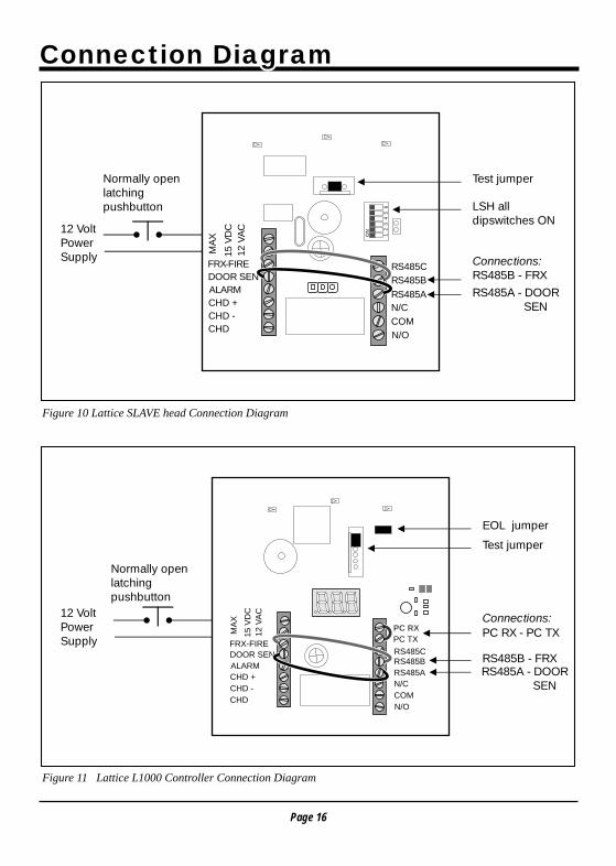
LSH TestAddress dip switches, RS485 terminating resistor and RS4851. Connect the unit under test as per figure 10.2. Connect power to the device under test.3. Ensure all 5 LED's turn ON.4. Remove and replace the test jumper, refer to figure 10.5. Wait for the buzzer to sound.6. All 5 LED's should turn OFF.
NOTE: The time taken between steps 7 and 9 that follow should not exceed 10 seconds.
7. Remove the test jumper, refer to figure 10.8. The buzzer should sound.9. Starting with DIP-Switch 6 (top down) push each of the DIP-Switches to OFF within 5 seconds of
each other.10. The buzzer should sound with each DIP-Switch press.11. After the last DIP-switch is pushed to OFF, turn the unit over.12. The TOP GREEN and BOTTOM GREEN LED's should remain ON.13. Should any of the above tests fail, return the unit to Centurion Systems, or a Centurion Systems
authorized distributor.14. LSH tests complete.
L1000 TestRS485 termination resistor, RS485 communications and take- up head communications test1. Connect the unit under test as per figure 11.2. Connect power to the device under test.3. Ensure all 3 LED's turn ON.4. Remove and replace the test jumper, refer to figure 11.5. Wait for the 3-digit, 7-segment display to show “brg”. (Bridge end of line terminals).
Communication InterfaceCommunication Interface
Page 15
Communication InterfaceNOTE: The time taken between steps 6 and 8 that follow should not exceed 10 seconds.
6. Remove the test jumper.7. The buzzer should sound and the 3-digit, 7-segment display should show “EOr”. (End of line . .
resistor).8. Remove the end of line jumper, refer to figure 11.9. The buzzer should sound and the 3-digit, 7-segment display should show “ScS”. (Success).10. Should any of the above tests fail, return the unit to Centurion Systems, or a Centurion Systems
authorized distributor.11. L1000 tests complete.
DOOR SEN RS485C
PC TX
RS485B
RS485A
N/C
COM
N/O
Test jumper
EOL jumper
Normally openlatching pushbutton
12
ON
34
56
CHDCHD -CHD +ALARMDOOR SENFRX-FIRE
12 V
AC
MA
X
15 V
DC
Test jumperNormally openlatching pushbutton
12 VoltPowerSupply
12 VoltPowerSupply
LSH all dipswitches ON
RS485B - FRX
RS485B - FRX
PC RX - PC TX
Connections:
Connections:
RS485A - DOOR SEN
RS485A - DOOR SEN
Page 16
Figure 10 Lattice SLAVE head Connection Diagram
Figure 11 Lattice L1000 Controller Connection Diagram
Connection DiagramConnection Diagram
CHD
CHD -
CHD +
ALARM
FRX-FIRE
12
VA
C
MA
X
15
VD
C
PC RX
RS485C
N/C
COM
N/O
RS485BRS485A

NotesNotes
Page 17

NotesNotes
Page 18

NotesNotes
Page 19

Sharecall 0860-CENTURION(Sharecall number applicable when dialed from within South Africa only)
(Omit (0) when dialing from outside South Africa)
or visit www.centsys.co.zafor details of your nearest agent
For technical support, contact:
South African Branches and Regional Distributors:
Other Countries:
Product Code:
Johannesburg Central/West Rand. . . . . . . . . . . . . . . . . . . . . . . . . . . . . . . . . . . . . . . . . 011-699-2400Johannesburg East-Rand . . . . . . . . . . . . . . . . . . . . . . . . . . . . . . . . . . . . . . . . . . . . . . . 011-397-6401Durban . . . . . . . . . . . . . . . . . . . . . . . . . . . . . . . . . . . . . . . . . . . . . . . . . . . . . . . . . . . . . . 031-701-9583Nelspruit . . . . . . . . . . . . . . . . . . . . . . . . . . . . . . . . . . . . . . . . . . . . . . . . . . . . . . . . . . . 013-752-8074/5Pretoria . . . . . . . . . . . . . . . . . . . . . . . . . . . . . . . . . . . . . . . . . . . . . . . . . . . . . . . . . . . . . . 012-349-1745Cape Town . . . . . . . . . . . . . . . . . . . . . . . . . . . . . . . . . . . . . . . . . . . . . . . . . . . . . . . . . . . 021-552-9425Port Elizabeth . . . . . . . . . . . . . . . . . . . . . . . . . . . . . . . . . . . . . . . . . . . . . . . . . . . . . . . 041-581-6994/5East London . . . . . . . . . . . . . . . . . . . . . . . . . . . . . . . . . . . . . . . . . . . . . . . . . . . . . . . . . . 043-743-4923Bloemfontein . . . . . . . . . . . . . . . . . . . . . . . . . . . . . . . . . . . . . . . . . . . . . . . . . . . . . . . . . 051-448-1714Kimberly . . . . . . . . . . . . . . . . . . . . . . . . . . . . . . . . . . . . . . . . . . . . . . . . . . . . . . . . . . . . . 053-832-3231Vereeniging . . . . . . . . . . . . . . . . . . . . . . . . . . . . . . . . . . . . . . . . . . . . . . . . . . . . . . . . . . 016-422-5667
Please refer to our website: www.centsys.co.za
Centurion Systems (Pty) Ltd Head Office:Tel: +27 (0)11-699-2400, Fax: +27 (0)11-704-3412 or (0)11-462-6669
148 Epsom Avenue, North RidingP.O. Box 506, Cramerview, 2060
South Africa
Latest Revision: 09.11.2007 Document Ref.: 1166.D.01.0010_2
Master address page: 0000.D.01.0004_5
© 2007 Centurion Systems (Pty) Ltd.