Embed Size (px)
Citation preview

L1000-L1000s
User Manual
The mind behind the drive

1
SBT Electric AC Drive SBT L1000/L1000s L1000 is an electrical AC drive for gearless elevator applications, which can be manufcatured in four different power ranges. This drive has been designed by SBT Electric in 2014. The drive provides necessary functions to ensure smooth and reliable operation of the motor at various speeds. In this manual, all functions are introduced and explained in detail.
Chapters The first chapter is dedicated to the initial settings and Auto-tuning, which calculates control parameters required to drive the AC motor. The second chapter explains the drive parameters and features. In the third chapter, procedures required to set the drive for elevator applications are explained. Failure diagnosis is also included in this chapter. Please read the manual carefully to tune the drive correctly.

2
Chapter 1: Initial Settings Overview
Properties Description Motor Power (kW) 5.5 7.5 11 15
Input Voltage (V) 3-phase 380V / 50 -60 Hz Output Voltage (V) 3-phase 0~380V / 0 ~ 100 Hz
Current (A) 14 18 24 31 Weight (Kg) 5.3 5.4 5.7 6.0
Mechanical Installation Dimensions: The drive dimensions needed for mechanical installation are mentioned in Table 1.1.
Figure 1.1: Drive box from different views
Table 1.1: Drive dimensions
Dimension A 205mm B 287mm D 215mm H 300mm W 217mm

3
Standard Connection Diagram Figures 1.2 (a) and 1.2 (b) show the connection between the power connector and drive control circuits in SBT L1000 and L1000s models, respectively. In L1000s model, the drive can be used in a single phase. It is also possible to set and run the drive via the digital operator without connecting digital I/O wiring. Refer to chapter 2 for further details.
Figure 1.2 (a): SBT-L1000 I/O block diagram

4
Figure 1.2 (b): SBT-L1000s I/O block diagram

5
Digital operator Use the digital operator to enter Run and Stop commands, edit parameters, and display data including fault and alarm information.
Figure 1.3: Keys and displays on the Digital Operator
No. Display Name Function
1 ESC Key • Returns to the previous display.
• Moves the cursor one space to the left. 2
RESET Key • Moves the cursor to the right. • Resets the drive to clear a fault situation.
3 RUN Key Run the motor when the drive is in the LOCAL
mode. 4 Up Arrow key Scrolls up to display the next item, select parameter
numbers, and increment setting values. 5 Down Arrow Key Scrolls down to display the previous item, select
parameter numbers, and decrements setting values. 6 STOP Key Stops drive operation. 7
ENTER Key • Enters parameter values and settings. • Selects a menu item to move between displays.
8
LO/RE Selection Key
Switches drive control between the operator (LOCAL) and the control circuit terminals (REMOTE) for the Run command and speed reference. The LED is on when the drive is in the LOCAL mode (operation from keypad). [Not available in SBT-L450]
9 FWD Light Lit while the drive runs in the forward direction.
10 REV Light Lit while the drive runs in the reverse direction.
11 MOD Light Lit when the energy injected by the drive is
negative. 12
RDY Light Lit when the drive is ready to operate.
1
2
3
4 5
6
7
8
9 10 1112 13 14
15 1617
FWDREVMODRDY

6
13 BB Light Lit when the drive is in the base block status.
14 ALM Light Blinks when an alarm occurs.
15 HZ x HZ Light <1> Lit when the chosen parameter is Hertz. 16 V . Voltage Light <1> Lit when the chosen parameter is Voltage. 17 A . Current Light <1> Lit when the chosen parameter is Amper.
<1> By choosing Watt or KiloWatt parameter, V and A Lights turn on. By choosing percent, V and Hz Lights turn on. By choosing millisecond or Second, Hz and A Lights turn on.
Menu structure The drive panel has seven display screens that cover user-accessible drive features. Hereafter, these menus are explained: Reference Speed and FWD/REV Command Screen [ ] This is the home screen menu which appears when the panel is just turned on or the escape key is pressed. Upper screen shows the speed reference while the lower one shows the direction of the rotation. If the b1-02 = 0, by pressing the Enter key you can change the motor's moving direction with UP/DWN keys. Output Speed and Current Screen [ ]: Output speed and current appear in upper and lower screens repectively. By pressing DWN key, output current screen appears. Monitoring (mmon): Monitor parameters let the user view various aspects of drive performance using the digital operator display. The values are updated online according to the drive condition. Auto-tuning (Atvn):
Based on the required motor parameters shown in this menu, the drive is capable of calculating necessary control parameters to run the motor efficiently. Setting (PAr):
In the setting menu, the user can edit and verify parameter settings. The number of accessible parameters is based on the control method set in A1-02. Modified Parameters (urfy): The parameters which have been modified and changed since the startup of the panel are shown in this menu. If the driver turns off or the panel resets, the list will be cleared.
BBALM
0000fvvd
00000000

7
Changing Parameter Values This example explains changing C1-02 (Deceleration Ramp 1) from 1.50 seconds to 2.50 seconds. The Blinking item has been displayed in gray color.
Display Step
Turn on the power to the drive. The initial
display appears. 1
Press or until the Parameter Setting screen ( ) appears.
2
Press to enter the parameter sub menu. 3
Press or to select the C parameter group.
4
Press two times. 5
Press or to select the parameter C1-02.
6
Press to view the current setting value (1.50 s). The left most digit blinks. 7
Press until the desired number is selected. “1” blinks.
8
Press until the desired number is 02.50. 9
Press to confirm the change. 10
The display automatically returns to the screen shown in Step 4. 11
Press as many times as necessary to
return to the initial display. 12
Auto-Tunning The drive offers deifferent types of Auto-Tuning for induction motors and permanent magnet motors .The type of Auto-Tuning used differs further based on the control mode and other operating conditions.

8
Auto-Tuning for Induction Motors and Permanent Magnet This feature automatically sets the motor parameters E1-** and E2-** for an Induction Motor and Encoder Offset for Permanent Magnet motor.
Table 1.2 Types of Auto-Tuning for Induction Motors Type Setting Requirements and Benefits V/f (0) OL(2) CLV (7)
Stationary Auto-tuning T1-01=3
• Automatically calculates motor parameters needed for open-loop and V/f control.
Yes Yes No
Encoder Offset Calculation T1-01=10 Automatically calculates Encoder offset. No No Yes
Table 1.3 lists the data that must be entered for Auto-Tuning. Make sure this data is available before starting Auto-Tuning. The necessary information is usually listed on the motor nameplate or in the motor test report provided by the motor manufacturer.
Table 1.3 Auto-Tuning Input Data
Input Value Input Parameter Unit
Tuning Type (T1-01)
3 Stationary
10 Encoder offset calculation
Motor Rated Power T1-02 kW Yes Yes Motor Rated Voltage T1-03 Vac Yes Yes Motor Rated Current T1-04 A Yes Yes Motor Rated Frequency T1-05 Hz Yes Yes Number of Motor Poles T1-06 - Yes Yes Motor Rated Speed T1-07 rpm Yes Yes Encoder resolution T1-08 PPR No Yes Basic Auto-Tuning Preparations and Precautions
WARNING! Electrical Shock Hazard. Do not touch the motor during Auto-Tuning. Lethal voltages may be present on the motor case. Failure to comply may result in serious injury from electrical
shock. WARNING! Electrical Shock Hazard. When executing Stationary Auto-Tuning for motor data, the motor does not rotate, however, power is applied. Do not touch the motor until Auto-Tuning is
completed. Failure to comply may result in death or serious injury from electrical shock.
Note: In automatic detection of offset encoder, if the encoder is sin – Cos ( ERN1387 ), the motor must rotate one round before Auto-tune to turn on the Mod light, then perform the Auto-tune operation.
Note: In the automatic calculation of encoder offset, although the test is in static mode, the mechanical brake must be in open condition and if the motor is connected to a load, it must be adjusted to be balanced on both sides. ( Do not move to the desired position by opening the brakes )
• When using a motor contactor, make sure it remains closed during the Auto-Tuning process. • Ensure Base_Block signal is ON when performing Auto-Tuning. • Ensure the motor is securely mounted and bolted in place prior to Auto-Tuning. • To cancel Auto-Tuning, press the STOP key on the digital operator. • Make sure motor nameplate data is readily available before Auto-Tuning the drive. Auto-
Tuning requires the user to input data from the motor nameplate or motor test report.

9
Auto-Tuning Operation Example
Selecting the Type of Auto-Tuning
The example below shows how to select the type of Auto-Tuning.
Step Display/ Result 1. Turn on the power to the drive. The initial display
appears.
2. Press or until the Auto-Tuning display appears.
3. Press to begin setting parameters. 4. Press to select the value for T1-01. 5. Save the setting by pressing 6. The display automatically returns to the display
shown in Step 3. Enter Data from the Motor Nameplate After selecting the type of Auto-Tuning, enter the data required from the motor nameplate.
Step Display/ Result 1. Press to access the motor output power
parameter T1-02.
2. Press to view the default setting. 3. Press , and to enter the motor
power nameplate data in kW. 4. Press to save the setting. 5. The display automatically returns to the display in
Step 1.
6. Repeat Steps 1 through 5 to set the following parameters: • T1-03, Motor Rated Voltage • T1-04, Motor Rated Current • T1-05, Motor Base Frequency • T1-06, Number of Motor Poles • T1-07, Motor Base Speed • T1-08, Encoder Resolution

10
Starting Auto-Tuning
WARNING! Electrical Shock Hazard. High voltage will be supplied to the motor when Stationary Auto-Tuning is performed even with the motor stopped, which could result in death or serious
injury. Do not touch the motor until Auto-Tuning has been completed.
Step Display/Result 1. After entering the data listed on the motor nameplate,
press to confirm. 2. Press to activate Auto-Tuning. 3. Auto-Tuning finishes in approximately five seconds.
Parameter Settings during Induction Motor Auto-Tuning and Permanet Magnet Motor : T1 T1-01: Auto-Tuning Mode Selection Sets the type of Auto-Tuning to be used.
No. Parameter Name Setting Range Default T1-01 Auto-Tuning Mode Selection 3 , 10 3
Setting 3: Stationary Auto-tuning Setting 10: Encoder Offset detection
T1-02: Motor Rated Power It sets the motor rated power according to the motor nameplate value.
No. Parameter Name Setting Range Default T1-02 Motor Rated Power 0 to 8.25 kW 5.3 kW
T1-03: Motor Rated Voltage
It sets the motor rated voltage according to the motor nameplate value.
No. Parameter Name Setting Range Default T1-03 Motor Rated Voltage 0 to 380 V 380 V
T1-04: Motor Rated Current It sets the motor rated current according to the motor nameplate value. Enter the current at the motor base speed.
No. Parameter Name Setting Range Default T1-04 Motor Rated Current 2 to 24 A 12 A
T1-05: Motor Base Frequency It sets the motor rated frequency according to the motor nameplate value.
No. Parameter Name Setting Range Default T1-05 Motor Base Frequency 0 to 50 Hz 50 Hz

11
T1-06: Number of Motor Poles It sets the number of motor poles according to the motor nameplate value.
No. Parameter Name Setting Range Default T1-06 Number of Motor Poles 2 to 48 4
T1-07: Motor Base Speed It sets the motor rated speed according to the motor nameplate value.
No. Parameter Name Setting Range Default T1-07 Motor Base Speed 300 to 3000 rpm 1380 rpm
T1-08: Encoder resolution (pulses per revolution) It sets the number of pulses from the PG encoder. Set the actual number of pulses for one full motor rotation.
No. Parameter Name Setting Range Default T1-08 Encoder number of Pulses Per Revolution 0 to 60000 ppr 2048 ppr
Chapter 2: Parameter Details A: Initialization The initialization group contains parameters associated with the initial setup of the drive. Parameters involving the initialization and control method are located in this group.
A1-02: Control Method Selection Selects the Control Method (also referred to as the control mode) that the drive uses to operate the motor.
No. Parameter Name Setting range Default A1-02 Control Method Selection 0,2,3,7 2
Setting 0: V/f Control for Induction Motors Use this mode for simple speed control. This method sets the output voltage based on the motor voltage-frequency curve. Setting 2: Open-Loop Control Use this mode for general applications that require more precise speed control and quicker torque response than V/f. Setting 3: Closed-Loop Control Use this mode to drive an induction motor with encoder feedback. This mode offers high-performance control down to 0 rpm motor speed. Setting 7: PM Closed-Loop vector Control Use this mode to drive an permanent magnet motor with encoder feedback. This mode offers high-performance control down to 0 rpm motor speed.

12
A1-03: Factory Reset Resets parameters back to their default values.
No. Parameter Name Setting range Default A1-03 Factory Reset 0,1 0
Setting 0: No Function Setting 1: Factory Reset
b: Application b1: Operation Mode Selection b1-02: Up/Down Command Selection Determines the Up/Down command source in the REMOTE mode. Wire the motor so the elevator goes up when an Up command is issued.
No. Parameter Name Setting Range Default b1-02 Up/Down Command Selection 0 to 1 1
Setting 0: Operator Allows the user to enter Up/Down commands from the digital operator. Use this setting when performing a test run only. In this mode, the speed reference is determined by d1-01. Setting 1: Control Circuit Terminal Up/Down commands are issued from the control circuit terminals. This is the standard setting used in most elevator applications.
b1-08: Up/Down Command Selection while in Programming Mode As a safety precaution, the drive will not normally respond to a Up/Down command input when the digital operator is being used to adjust a parameter in the Programming Mode (Verify Menu, Setup Mode, and Auto-Tuning Mode). If required by the application, set b1-08 to allow the drive to run while in the Programming Mode.
No. Parameter Name Setting Range Default b1-08 Up/Down Command Selection while in
Programming Mode 0 to 2 1
Setting 0: Disabled A Up/Down command is not accepted while the digital operator is in the Programming Mode. Setting 1: Enabled A Up/Down command is accepted in any digital operator mode. Setting 2: Prohibit programming during run It is not possible to enter the Programming Mode as long as the drive output is active. The Programming Mode cannot be displayed during Run. b3-01: Detection light load direction Enable or disable light load experiment
No. Parameter Name Setting Range Default b3-01 Detection light load direction 0 , 1 1

13
Setting 0: Disable If this parameter is set to 0, the drive will move in the direction that has been issued from the control center, while the drive itself is in rescue mode and the light load orientation detection test no longer will be performed by the drive in this situation. Setting 1: Enable If this parameter is set to 1, the driver will perform a light load direction test in rescue mode. Any direction command issued from the control center will be ignored by the driver. C: Tuning C parameters are used to set the acceleration and deceleration characteristics, as well as jerk. Other parameters in this group cover setting for torque compensation and PI controller in closed-loop control.
C1: Acceleration and Deceleration Ramps C1-01 to C1-04 and C1-09: Accel, Decel Ramps 1 and 2 and Fast Stop Ramp Five parameters can be set in the SBT-L1000 for tuning acceleration and deceleration ramp. Acceleration ramp parameters always set the ramp or time to accelerate from 0 to the maximum speed (E1-05). Deceleration ramp parameters always set the ramp or time to decelerate from the maximum speed (E1-05) to 0. In this version (SBT-L1000), C1-01 is used for acceleration time. C1-02 is used when the motor decelerates from any speed to any other speed (except nominal and leveling speed to zero speed). C1-04 is used when the motor decelerates from leveling speed to zero speed. C1-09 determines the deceleration ramp from nominal speed to zero speed.
Note 1: If C1-04=0, deceleration from leveling speed will be set according to the value set in C1-02.
Note 2: By setting C1-09 to zero, if the motor speed shifts from its nominal speed, the drive immediately applies the brake and coast to stop.
No. Parameter Name Application Setting Range Default C1-01 Acceleration Ramp 1 Any speed to any speed
0.00 to 180.00 s
3
C1-02 Deceleration Ramp 1
Any speed to any speed (Except nominal and leveling speed to zero
speed)
2
C1-04 Deceleration Ramp 2 Leveling speed to zero speed 4
C1-09 Fast Stop Ramp Nominal speed to zero speed 0
C1-15: Inspection Deceleration Ramp Sets the deceleration ramp during Inspection Run. If this parameter is set to 0s, the drive coasts to stop.
No. Parameter Name Setting Range Default C1-15 Inspection Deceleration Ramp 0.00 to 2.00 s 2.00 s

14
C2: Jerk Settings
Jerk settings set the transition between acceleration rates. Adjust them to smooth out jerks or shocks that occur when the speed is changing. C2-01 to C2-05: Jerk Settings C2-01 through C2-05 set separate jerks for each section of the acceleration or deceleration.
No. Parameter Name Setting Range Default C2-01 Jerk at Accel start
0 to 7 3 C2-02 Jerk at Accel end C2-03 Jerk at Decel start C2-04 Jerk at Decel end C2-05 Jerk at leveling speed
Figure 2.1: Jerk Settings
The transition time between accelerating and decelerating ramps is expressed by discrete numbers in SBT-L1000. Eight S-curve settings are available, and are expressed as below: 0: No S Curve 1: Very low 2: Low 3: Intermediate 1 4: Intermediate 2 5: Intermediate 3 6: High 7: Very high Adjusting low numbers leads to shock while high numbers slow the operation. The optimum operation can be obtained by setting these parameters to 3 or 4.
C4: Torque Compensation The torque compensation function compensates for insufficient torque production at start-up or when a load is applied.
Note 1: Set the motor parameters (E2-**) and V/f pattern properly before setting torque compensation parameters. Note 2: These parameters are not active in the closed-loop control mode for PM motor (A1-02 = 7).

15
C4-01: Torque Compensation Gain Sets the gain for the torque compensation function.
No. Parameter Name Setting Range Default C4-01 Torque Compensation Gain 0.00 to 5.00 1.5
Adjustment Although this parameter rarely needs to be changed, it may be necessary to adjust the torque compensation gain in small steps of 0.1 in the following situations: • Increase this setting when using a long motor cable, or when the starting torque is not high enough to accelerate the motor. • Increase this setting when motor vibrates in Regenerative mode and leveling speed. • Decrease this setting when motor vibrates in Motoring mode and leveling speed. • Adjust C4-01 so that the output current does not exceed the drive rated current. C4-02: Torque Compensation Primary Delay Time It sets the delay time used for applying torque compensation.
No. Parameter Name Setting Range Default C4-02 Torque Compensation Primary Delay Time 0.0 to 2000.0 ms 200.0 ms
Adjustment Although C4-02 rarely needs to be changed, adjustments may be necessary in the following situations: • Increase this setting if the motor vibrates. • Decrease this setting if the motor responds too slowly to changes in the load.
C5: Speed Control Loop These parameters are accessible only in the closed-loop control mode. The Speed control Loop Controls the motor speed in CLV and CLV/PM control modes. It adjusts torque reference in order to minimize the difference between speed reference and actual motor speed. The speed control block diagram has been shown in fig2.2.
Figure 2.2: Speed Control Block Diagram
C5-01, C5-03, C5-13 / C5-02, C5-04, C5-14: Speed Control Loop Proportional Gain 1, 2, 3 / Speed Control Loop Integral Time 1, 2, 3 These parameters can be used to adjust the responsiveness of the Speed Control Loop.
No. Parameter Name Setting Range Default C5-01 Speed Control Loop Proportional Gain 1 0 to 255 82 C5-02 Speed Control Loop Integral Time 1 0 to 8191ms 1200ms C5-03 Speed Control Loop Proportional Gain 2 0 to 255 100 C5-04 Speed Control Loop Integral Time 2 0 to 8191ms 1200ms C5-13 Speed Control Loop Proportional Gain 3 0 to 255 40 C5-14 Speed Control Loop Integral Time 3 0 to 8191ms 5000ms

16
It is important to change the coefficients of the speed controllers properly in order to drive the motor in a soft and smooth way. The accelerating procedure of P and I coefficients for start and stop modes are shown in Fig. 2-3, (a) and (b) respectively.
(a)
(b)
Figure 2.3 Settings at Low and High Speed during Acceleration
C5-06: Speed Control Loop Primary Delay Time Constant
This parameter sets the filter time constant for the time from the speed loop to the torque command output. Increase this setting gradually in increments of 0.01 for loads with low rigidity, or when oscillation is a problem. The excessive increase of this parameter will cause problems.
No. Parameter Name Setting Range Default C5-06 Speed Control Loop Primary Delay Time Constant 0 to 500ms 20ms
C5-19, C5-20: Speed Control Loop P Gain Time, I Time during Position Lock These two parameters are used to adjust the responsiveness of Speed Control Loop during Position Lock. Incorrect adjustment causes a rollback after the brake releases or motor oscillation.
No. Parameter Name Setting Range Default C5-19 Speed Control Loop Proportional Gain Time during Position Lock 0 to 255 1000 C5-20 Speed Control Loop Integral Time during Position Lock 0 to 8191ms 5000ms
d: Reference Settings The d family parameters determine the speed of the elevator including the speed reference. d1: Speed Reference The parameters of this family adjust the reference speed of the drive in different conditions.

17
d1-01 to d1-08: Speed References 1 to 8 The drive lets the user switch between 8 preset frequency references during run by using the digital input terminals.
No. Parameter Name Setting Range Default d1-01 Speed Reference 1
0.00 to E1-04 Hz
10 Hz d1-02 Speed Reference 2
0 Hz
d1-03 Speed Reference 3 d1-04 Speed Reference 4 d1-05 Speed Reference 5 d1-06 Speed Reference 6 d1-07 Speed Reference 7 d1-08 Speed Reference 8
Multi-Step Speed Selection To use several speed references for a multi-step speed sequence, set the H1-** parameters to 0,1,2.
Reference Multi-step Speed
1 H1-**=0
Multi-step Speed 2
H1-**=1
Multi-step Speed 3
H1-**=2 Frequency Reference 1 OFF OFF OFF Frequency Reference 2 ON OFF OFF Frequency Reference 3 OFF ON OFF Frequency Reference 4 ON ON OFF Frequency Reference 5 OFF OFF ON Frequency Reference 6 ON OFF ON Frequency Reference 7 OFF ON ON Frequency Reference 8 ON ON ON
d1-17: JOG Speed Selection This parameter adjusts the speed that is related to JOG.
No. Parameter Name Setting Range Default d1-17 JOG Speed 0 to E1-04 0.3Hz
d1-18: Speed Reference Selection Mode This parameter sets the priority of the speed reference inputs.
Note1: Always turn off the RUN command before changing the setting of parameters d1-18 (Speed Reference Selection Mode), d1- 01 (Speed Reference Selection).If the RUN command is on, when changing any of these settings,
the motor may unexpectedly start running and could result in injury.
No. Parameter Name Setting Range Default d1-18 Speed Reference Selection Mode 0 to 2 1
Setting 0: Use multi-speed references d1-01 to d1-08 These parameters set speed references 1 through 8. Each of these speed reference values can be selected using digital inputs programmed for multi-speed selection (H1-**). Setting 1: High-speed reference has priority Four different speed parameters (d1-19, d1-20, d1-24, d1-26) can be programmed. If any of these speed parameters and leveling speed, activated at the same time, speed parameters have priorities over leveling speed parameter. Setting 2: Low-speed reference has priority Four different speed parameters (d1-19, d1-20, d1-24, d1-26) can be programmed. If any of these speed parameters and leveling speed, activated at the same time, the leveling speed has priority over speed parameters.

18
d1-19: Nominal Speed Sets the nominal speed, and it is used as the motor reference speed when a digital command for the Nominal input terminal is issued (H1-**=6).
No. Parameter Name Setting Range Default d1-19 Nominal Speed 0.00 to E1-04 50 Hz
d1-20: Intermediate Speed Sets intermediate speed.
No. Parameter Name Setting Range Default d1-20 Intermediate Speed 0.00 to 50.00 Hz 30.00 Hz
d1-24: Inspection Operation Speed It sets the inspection speed, and it is used as the motor reference speed when a digital command for the Inspection input terminal is issued (H1-**=9).
No. Parameter Name Setting Range Default d1-24 Inspection Operation Speed 0.00 to 50.00 Hz 15.00 Hz
d1-25: Rescue Operation Speed While digital input has been set to rescue mode (H1-**=10), this parameter determines the speed during Rescue Operation.
No. Parameter Name Setting Range Default d1-25 Rescue Operation Speed 0 to E1-04 5.00Hz
d1-26: Leveling Speed It sets the Leveling speed, and it is used as the motor reference speed when a digital command for the Leveling input terminal is issued (H1-**=8).
No. Parameter Name Setting Range Default d1-26 Leveling Speed 0.00 to 50.00 Hz 5.00 Hz
E: Motor Parameters E parameters cover V/f pattern and motor data settings.
Note: In closed-loop mode, only frequency and nominal voltage (E1-04, E1-05) are Customizable, which after the auto-tuning, they will be adjusted by the drive automatically.
E1: V/f Pattern
E1-02: V/f Mode No. Parameter Name Setting Range Default
E1-02 V/f Mode 0 to 3 3 Setting 0: Normal V/f In this mode, the drive uses V/f curve based on Maximum Voltage (E1-05) and Maximum frequency (E1-04). In all reference speeds, this ratio is kept constant. Setting 1: Torque Compensation In this mode, the torque is increased to prevent motor stall under heavy loads. Setting 2: Manual Curve
In this mode, the user can adjust the voltage-speed curve by setting parameters E1-05 through E1-13.
Be careful to set these parameters correctly, otherwise, the motor will show unexpected behavior or overload fault will occur due to the saturation of the motor magnetic core.

19
Setting 3: Boost Manual Curve (Recommended) In this mode, the voltage-speed curve is set according to parameters E1-05 through E1-13, and starting torque is increased to prevent motor stall under heavy loads. Besides, voltage offset could be added to all points in the curve by using E1-03. The voltages-speed curve will be according to Fig. 2.2. Use this option when the motor is under heavy loads, or high starting torque is required.
E1-03: Voltage Offset
No. Parameter Name Setting Range Default E1-03 Voltage Offset 0V to 50V 0V
The voltage-speed curve set by parameters E1-05 through E1-13 could be further modified by adding a constant voltage. The amount of added voltage could be set in E1-03. If the motor stalls, increase voltage offset to increase the torque. Note that E1-03 is used when E1-02 is set to 3 or 1.
V/f Pattern Settings E1-04 to E1-13
No. Parameter Name Setting Range Default E1-04 Maximum Output Frequency 0 to 50Hz 50 Hz E1-05 Maximum Voltage 0.0 to 380.0 V 380.0 V E1-06 Voltage at 16/32 Max Frequency 0.0 to 380.0 V 167V E1-07 Voltage at 12/32 Max Frequency 0.0 to 380.0 V 121 V E1-08 Voltage at 10/32 Max Frequency 0.0 to 380.0 V 92 V E1-09 Voltage at 8/32 Max Frequency 0.0 to 380.0 V 75 V E1-10 Voltage at 6/32 Max Frequency 0.0 to 380.0 V 55 V E1-11 Voltage at 5/32 Max Frequency 0.0 to 380.0 V 45 V E1-12 Voltage at 4/32 Max Frequency 0.0 to 380.0 V 35 V E1-13 Voltage at 3/32 Max Frequency 0.0 to 380.0 V 25 V
Figure 2.2 Manual V/f curve
Voffset (E1-03)
E1-13E1-12E1-11E1-10
E1-09
E1-08
E1-07
E1-06
E1-05
E1-04 (fmax)
16/3212/32 10/328/32
6/32
5/32
4/32
3/32
Voltage(V)
f (Hz)

20
E2: Motor Parameters These parameters contain the motor data. They are set automatically when Auto-Tuning is performed.
E2-01: Motor Rated Current Used to protect the motor and calculate drive control parameters. Set E2-01 to the full load amps (FLA) stamped on the motor nameplate. If Auto-Tuning completes successfully, the value entered to T1-04 will automatically be saved to E2-01.
No. Parameter Name Setting Range Default E2-01 Motor Rated Current 2 to 18A 12A
E2-02: Motor Rated Slip Sets the motor rated slip in Hz to protect the motor and calculate drive control parameters. This value is automatically set during Auto-Tuning. This parameter is disable in PM close loop control.
No. Parameter Name Setting Range Default
E2-02 Motor Rated Slip 0.00 to 20.00 Hz 4 Hz
E2-03: Motor No-Load Current Sets the no-load current for the motor in amperes when operating at the rated frequency. The drive sets E2-03 during the Auto-Tuning process. Please note that if this parameter is set to 0, output phase loss fault detection will be disabled.
No. Parameter Name Setting Range Default E2-03 Motor No-Load Current 0 to18A 4A
E2-04: Number of Motor Poles Sets the number of motor poles to E2-04. If Auto-Tuning completes successfully, the value entered to T1-06 will automatically be saved to E2-04.
No. Parameter Name Setting Range Default E2-03 Number of motor poles 2 to 48 4
E2-05: Motor Line-to-Line Resistance Sets the line-to-line resistance of the motor stator winding. If Auto-Tuning completes successfully, this value is automatically calculated. Enter this value as line-to-line and not for each motor phase.
No. Parameter Name Setting Range Default E2-05 Motor Line-to-Line Resistance 0.000 to 13.000 Ω 2 Ω
E2-11: Motor Rated Power Sets the motor rated power in kW. If Auto-Tuning completes successfully, the value entered to T1-02 will automatically be saved to E2-11.
No. Parameter Name Setting Range Default E2-11 Motor Rated Power 0.00 to 15 kW 5.5 kW

21
H: Terminal Functions H parameters are used to assign functions to the external terminals.
H1: Multi-Function Digital Inputs
H1-03 to H1-06: Functions for Terminals S3 to S6 These parameters assign functions to the multi-function digital inputs. The various functions and settings are listed in the table below.
No. Parameter Name Setting Range Default H1-03 Multi-Function Digital Input Terminal S3
Function Selection 0 to 14 6
H1-04 Multi-Function Digital Input Terminal S4 Function Selection
0 to 14 9
H1-05 Multi-Function Digital Input Terminal S5 Function Selection
0 to 14 7
H1-06 Multi-Function Digital Input Terminal S6 Function Selection
0 to 14 8
Setting Function
0 Multi-Speed Reference 1
1 Multi-Speed Reference 2
2 Multi-Speed Reference 3
6 Nominal Speed
7 Intermediate Speed
8 Leveling Speed
9 Inspection Operation
11 Baseblock Command (N.O.)
12 Baseblock Command (N.C.)
13 Fault Reset
14 External Fault
Setting 0 to 2: Multi-Step Speed Reference 1 to 3 By setting three of the digital inputs to 1 to 3, 8 reference speeds set at d1-01 through d1-08 can be accessed. Refer to d1: Frequency Reference for more details.
Setting 6: Nominal Speed Closing a terminal set for “Nominal speed” makes the drive run at the speed reference set to d1-19. Conditions change, however, according to the speed selection mode set in d1-18.
Setting 7: Intermediate Speed Closing a terminal set for “Intermediate speed” makes the drive run at the speed reference set to d1-20. Conditions change, however, according to the speed selection mode set in d1-18. Setting 8: Leveling Speed Closing a terminal set for “Leveling speed” makes the drive run at the speed reference set to d1-26. Conditions change, however, according to the speed selection mode set in d1-18.
Setting 9: Inspection Operation It causes the drive to operate at the speed reference set in the d1-24 parameter. To use Inspection Run, the terminal must be configured before the Up/Down command issued.

22
Setting 10: Rescue Operation Closing a terminal set for “Rescue operation” makes the drive run at d1-25 conditions.
Setting 11, 12: Baseblock Command (N.O., N.C.) When the driver receives a baseblock command, the output transistors stop switching and the motor coasts to stop.
Setting 13: Fault Reset When the drive detects a fault condition, the fault output contactor closes, the drive output shuts off, and the motor coasts to stop. After disabling the Run command, clear the fault either by pressing the RESET key on the digital operator or closing a digital input configured as a Fault Reset (H1-**=13).
Note: Disable the Run command prior to resetting a fault. Otherwise, "cannot reset fault" will appear on the digital operator.
Setting 14: External Fault The External fault command stops the drive when problems occur with external devices. To use the External fault command, set one of the multi-function digital inputs to 14. The digital operator will display EF.
H2: Multi-Function Digital Outputs H2-03: Terminals M5-M6 Function Selection
No. Parameter Name Setting Range Default H2-03 Multi-Function relay function 0 to 6 0
Setting 0: During Run
This relay is absorbed during the run
Setting 1: Speed Agree
If the drive output frequency is lower than the set value in parameter L4-01, the relay is absorbed.
Setting 2: Drive Ready
If the driver is without errors, the relay is absorbed.
Setting 3: Baseblock command (NO)
When the baseblock is disabled, the relay is absorbed.
Setting 4: Fault
When a fault occurs, the relay is absorbed.
Setting 5: Reverse
When the motor moves in the Reverse direction, the relay is absorbed.
Setting Function 0 During Run 1 Speed Agree 2 Drive Ready 3 Baseblock command(NO) 4 Fault 5 Reverse 6 Baseblock command(NC)

23
Setting 6: Baseblock command (NC)
When the Baseblock is enabled, the relay is absorbed.
L: Protection Functions L1: Motor Protection
L1-02: Motor Overload Protection Time It Sets the time that the drive will subsequently shut down due to the motor overload (oL1) when the motor is running with excessive current. Enter the time the motor can withstand operating at 150% current. This parameter rarely requires adjustment.
No. Parameter Name Setting Range Default L1-02 Motor Overload Protection Time 6 s to 90 s 60 s
L1-08: oL1 Current Level It Sets the current level for motor overload detection. This parameter should be set as a percentage of the motor rated current (E2-01).
No. Parameter Name Setting Range Default L1-08 oL1 Current Level 100% to 150% 150%
L4: Speed Detection L4-01: Speed Agreement Detection Level
Determine the speed at which, speed levels less than this level will cause Speed Agree relay to be absorbed.
No. Parameter Name Setting Range Default L4-01 Speed Agree 0 to 50Hz 2
L5: Automatic Fault Reset When an error occurs in the driver, these parameters can be used to clear the faults automatically and let the driver continue in its normal operation.
L5-01: Number of Auto Reset Attempts
If L5-01 is set to 0, the drive fault must be reset manually. Otherwise, the drive tries to automatically reset the fault and continues operation.
DANGER! In some applications, it is not safe to clear a fault automatically. Automatic fault restart function should not be enabled in such applications.
No. Parameter Name Setting Range Default
L5-01 Number of Auto Reset Attempts 0 to 1 0

24
o: Operator Related Settings o3: Copy Function These parameters are used to adjust and control the Copy function of the digital operator. The Copy function, stores parameter settings into the memory of the digital operator to facilitate the transfer of those stored settings to other drivers with the same model, capacity, and control mode setting.
o3-01 Copy Function Selection Instructs the drive to Read, Write, or Verify parameter settings.
No. Parameter Name Setting Range Default o3-01 Copy Function Selection 0 to 3 0
Setting 0: Copy Select (no function) Setting 1: INV →OP READ Copies all parameters from the drive to the digital operator.
Note: The copy protection for the digital operator is enabled by default. Set o3-02 to 1 to unlock copy protection.
Setting 2: OP →INV WRITE Copies all parameters from the digital operator to the drive. Setting 3: OP ↔INV VERIFY Parameters in the drive are compared with the parameter settings saved on the digital operator to see if they match. o3-02 Copy Allowed Selection It allows and restricts the use of the Copy function.
No. Parameter Name Setting Range Default o3-02 Copy Allowed Selection 0 or 1 0
Setting 0: Disabled Setting 1: Enabled
S: Elevator Parameters This section describes various functions needed to operate an elevator application: braking sequence and slip compensation. S1: Brake Sequence S1-00: Zero Speed Level at Start Determines the frequency to begin acceleration after DC Injection. This parameter is disable in close loop control mode.
No. Parameter Name Setting Range Default S1-00 Zero Speed Level at Start 0.00 to 10.00 0.2
S1-01: Zero Speed Level at Stop Determines the frequency to begin applying DC Injection when the drive is ramping to stop. This parameter is disable in close loop control mode.
No. Parameter Name Setting Range Default S1-01 Zero Speed Level at Stop 0.00 to 10.00 0.2
25
S1-02: DC Injection Current at Start Determines the amount of current to use for DC Injection at the start. Set as a percentage of the motor rated current. This parameter is disable in close loop control mode.
No. Parameter Name Setting Range Default S1-02 DC Injection Current at Start 0 to 100% 70%
S1-03: DC Injection Current at Stop Determines the amount of current to use for DC Injection at the stop. Set as a percentage of the motor rated current. This parameter is disable in close loop control mode.
No. Parameter Name Setting Range Default S1-03 DC Injection Current at Stop 0 to 100% 80%
S1-04: DC Injection / Position Lock Time at Start Determines how long the drive should perform DC Injection at the start. During this time, the drive allows motor flux to develop, which is essential for applying torque quickly once the brake is released.
No. Parameter Name Setting Range Default S1-04 DC Injection Time at Start 0.00 to 10.00 s 0.40 s
S1-05: DC Injection / Position Lock Time at Stop Determines how long the drive should perform DC Injection at the stop. A setting of 0.00 disables S1-05.
No. Parameter Name Setting Range Default S1-05 DC Injection Time at Stop 0.00 to 10.00 s 0.60 s
S1-06: Brake Release Delay Time Determines the time that must pass after an Up/Down command is entered before the output terminal set for "Brake control" is triggered. Adjusting this delay time can help when there is not enough time to develop the appropriate amount of motor flux. Be sure to also increase the time S1-04 when setting S1-06 to relatively long delay time.
No. Parameter Name Setting Range Default S1-06 Brake Release Delay Time 0.00 to 10.00s 0.20 s
S1-07: Brake Close Delay Time Determines the time that must pass after zero speed is reached before the output terminal set for "Brake control" is released.
No. Parameter Name Setting Range Default S1-07 Brake Close Delay Time 0.00 to 10.00s 0.30 s
S1-10: Run Command Delay Time Sets the time the drive waits after receiving an Up/Down command before starting operation. The time set should give the motor contactor enough time to close.
No. Parameter Name Setting Range Default S1-10 Run Command Delay Time 0.00 to 1.00 s 0.20s

26
S1-11: Output Contactor Open Delay Time Determines the time that must pass for an output terminal set for “Output contactor control” to be released after the drive has stopped and drive output has been shut off.
No. Parameter Name Setting Range Default S1-11 Output Contactor Open Delay Time 0.00 to 1.00 s 0.20 s
S1-12: Motor Contactor Control During Auto-Tuning Selection Determines the state of the output contactor control command during Auto-Tuning. If S1-12 is set to 1, the motor contactor will be closed during auto-tuning.
No. Parameter Name Setting Range Default S1-12 Motor Contactor Control during Auto-Tuning 0 to 1 0
Setting 0: Disabled Setting 1: Enabled
S2: Slip Compensation for Elevators The slip compensation function automatically adjusts the speed reference for leveling operation depending on the load measured at a constant speed. S2 parameters tune the slip compensation function to improve the landing accuracy. Slip Compensation requires that the drive be set for Open-Loop Control (A1-02 = 2). S2-01: Motor Rated Speed Sets the rated speed of the motor.
No. Parameter Name Setting Range Default S2-01 Motor Rated Speed 300 to 3000 rpm 1380 rpm
S2-02/S2-03: Slip Compensation Gain in Motoring Mode / Regenerative Mode Slip compensation for leveling speed can be set separately for motoring and regenerative states to help improve the accuracy of leveling. Refer to chapter 3 for further information.
No. Parameter Name Setting Range Default S2-02 Slip Compensation Gain in Motoring Mode 0.0 to 4.0 1
S2-03 Slip Compensation Gain in Regenerative Mode 0.0 to 4.0 0.5
S2-06: Slip Compensation Torque Detection Filter Time Constant Sets the filter time constant applied to the torque signal used for the slip compensation value calculation.
No. Parameter Name Setting Range Default S2-06 Slip Compensation Torque Detection Filter
Time Constant 0 to 2000 ms 2000 ms
S3: Start / Stop Optimization
S3-01: Position Lock Gain at Start Sets the gain used by the position lock control loop at start. Position Lock at start adjusts the internal tourqe reference value depending on the position deviation in order to hold the car in place when when brake is released. S3-01 sets the gain used to adjust the speed reference during position lock. .
No. Parameter Name Setting Range Default S3-01 Position Lock Gain at Start 0 to 100 3

27
S3-03: Position Lock Gain at Stop Sets the gain used by the position lock control loop at stop. This is used to hold the car in place whie the brake applies. Setting S3-03 to a high value will increase the drives ability to hold the car in place but too high of a setting can result in motor oscillation. .
No. Parameter Name Setting Range Default S3-03 Position Lock Gain at stop 0 to 100 3
U: Monitoring Parameters Monitor parameters let the user view various aspects of drive performance using the digital operator display. The monitor parameters available in this version (SBT-L1000) are indicated in table 2.1.
Table 2.1: Monitoring parameters No. Name Description
U1-01 Speed Reference Monitors the speed reference. U1-02 Output Speed Monitors the output speed. U1-03 Output Current Displays the output current. U1-05 Speed feedback Display the motor speed feedback. U1-06 Output Voltage Reference Displays the output voltage. U1-07 DC Bus Voltage Displays the DC bus voltage. U1-08 Output Power Displays the output power (this value is calculated internally).
U1-10 Input Terminal Status
Displays the input terminal status.
U1-11 Output Terminal Status
Displays the output terminal status.
U3-01 to U3-08 First to 8th Recent Fault
Displays the first to the eighth most recent faults. After eight faults have occurred in the drive, data for the oldest
fault is deleted. The most recent fault appears in U3-01, with the next most recent fault appearing in U3-02. The data is moved to
the next monitor parameter every time a fault occurs. U4-08 Heatsink Temperature Displays the heatsink temperature U6-01 Motor Secondary Current (Iq) Displays the value of the motor secondary current (Iq).
U6-02 Motor Excitation Current (Id) Displays the value calculated for the motor excitation current
(Id).
U6-05 Output Voltage Reference (Vq) Output voltage reference (Vq) for the q-axis. U6-06 Output Voltage reference (Vd) Output voltage reference (Vd) for the d-axis.
Not UsedS1 (UP)S2 (DOWN)S3 (Nominal)S4 (Inspection)S5 (Intmed1)S6 (Leveling)
i i i i i i i i
Fault relay
DO (During run)Ready relayMotor contactor relayBreak relay
Not used
i i i i i i i i

28
Failure Diagnosis Faults are detected for drive protection, and cause the drive to stop while triggering the fault output terminal MA-MB MC. Remove the cause of the fault and manually clear the fault before attempting to run the drive again.
Fault Name symbol Description Cause
Memory Data Error
EEPROM write error -The power supply was switched off while parameters were being saved to the drive.
External Fault
External Fault at multi-function -An external device has tripped a fault function. -I/O wiring is incorrect. -Incorrect multi-function contact input setting
Output Phase Loss
Phase loss on the output side of the drive.
-The output cable is disconnected. -The motor winding is damaged. -The output terminal is loose. -An output transistor is damaged. -The no-load current is set too high. -The Motor contactor is not set up correctly.
Short-circuit
Drive current exceeded short-circuit detection level (maximum allowable current)
-Accel/decel ramp is too short. -The current level increased due to a momentary power loss or while attempting to perform a fault reset. -The encoder and drive phase sequence are not the same. (Interchange A, B of the encoder)
Overcurrent
Drive current exceeded overcurrent detection level
-The Load is too heavy. -Accel/decel ramp is too short. -The current level increased due to a momentary power loss or while attempting to perform a fault reset.
Overload (oL1)
Drive current exceeded motor overload detection level
-The Load is too heavy. -Accel/decel ramp is too short.
Overload (oL2)
Drive current has been 2 times greater than the current value sets in E2-01 parameter
-The Load is too heavy. - The motor current is set incorrectly
Over Temperature
The temperature of the heatsink exceeded the overheat detection level
-The surrounding temperature is too high. -the Load is too heavy. -The internal cooling fan is stopped.
Over Voltage
Voltage in the DC bus has exceeded the overvoltage detection level.
-The Deceleration ramp is too short and regenerative energy is flowing from the motor into the drive. -Fast acceleration ramp causes the motor to overshoot the speed reference. -Drive input power voltage is too high. -The braking resistor is not connected, or wiring is wrong. -The braking resistance ohm is higher than standard values.

29
Under Voltage 1
Voltage in the DC bus fell below the under-voltage detection level
-Input power phase loss. -One of the drive input power wiring terminals is loose. -There is a problem with the voltage from the drive input power. -The power has been interrupted.
Under Voltage 2
Control Power Supply Voltage Fault
Control power supply wiring is damaged. Internal circuitry is damaged.
Operator Fault
The same function is assigned to two multi-function inputs.
The same function is assigned to two multi-function inputs.
Cannot Reset
When the error wants to be reset, the Up / down command has not been removed yet.
When the error wants to be reset, the Up / down command has not been removed yet.
Excessive Speed Deviation
The difference between the motor speed feedback and the reference speed is too high.
- The mechanical brake is not released. - The slope of the family c1 is too low. - Controller coefficients in c5 are not set correctly.
Encoder Fault
encoder card is not connected correctly or encoder is not working correctly.
The encoder card is not matched with encoder or there is a problem in encoder cable or encoder card is not connected correctly or encoder is damaged.
Encoder card OFC4 Encoder card is not working correctly
Encoder card is Not appropriate for this drive or encoder card is damaged.

30
Chapter 3: Tuning the drive for elevator application In this chapter, the procedures required to set the drive for elevator application are explained. First, conditions under which the drive starts and stops running are mentioned. Then, the procedure for setting the drive will be explained in 9 consecutive steps. Travel Start and Stop Travel Start To start the elevator in the up or down direction, the following conditions must be fulfilled: • A speed reference greater than zero must be provided. • A speed higher than zero should be selected by the digital operator or the digital inputs. • The Safe Disable signals at terminal H must be closed (drive output enabled). • An Up or Down Signal must be set at the source specified in b1-02. Travel Stop The drive stops under the following conditions: • The Up or Down command is removed. • d1-18 is set to 1 or 2 and the Up/Down or all speed signals (S3 to S6) are removed. • d1-18 is set to zero and the Up/Down is removed. • A fault occurs. The drive coasts to stop in this condition. • The Safe Disable inputs are opened or a Base Block signal is enabled. In this case, the brake is applied immediately and the drive output shuts off. To tune the drive for the elevator applications, the procedure indicated below is recommended:
Step 1: Up/Down Command Source Selection The input source for the Up and Down command can be selected using parameter b1-02. The digital operator could be used for the test purpose. Depending on the elevator main controller, digital inputs or Modbus communication could be used as the source of Up/Down command. (Modbus communication is not available in SBT-L1000).
b1-02 Up/Down Source Up/Down command input
0 Operator Keypad RUN and STOP keys on the operator
1 Digital Inputs Terminal S1: Run in the Up direction Terminal S2: Run in the Down direction
Step 2: Speed Selection Using Digital Inputs (b1-01 = 0) Use parameter d1-18 to determine different travel speeds selected by the digital inputs.
d1-18 Speed Selection 0 Multi-speed inputs 1, Speed references are set in d1-01 to d1-08
1 (default) Separate speed inputs, Speed references are set in d1-19 to d1-26 and Higher speed has priority
2 Separate speed inputs, Speed references are set in d1-19 to d1-26 and Leveling speed has priority

31
Multi-Speed Inputs (d1-18 = 0) Multi-speed inputs could be used by assigning Multi-speed references to digital inputs as shown in the table below:
Parameter Number Set value Details H1-** 0 Multi-speed Reference 1 H1-** 1 Multi-speed Reference 2 H1-** 2 Multi-speed Reference 3
Different speed reference settings can be selected by combining the three digital inputs as shown in the table below.
Digital Inputs Selected Speed Multi-Speed
Reference 1 Multi-Speed Reference 2
Multi-Speed Reference 3
0 0 0 Speed Reference 1 (d1-01) 1 0 0 Speed Reference 1 (d1-02) 0 1 0 Speed Reference 1 (d1-03) 1 1 0 Speed Reference 1 (d1-04) 0 0 1 Speed Reference 1 (d1-05) 1 0 1 Speed Reference 1 (d1-06) 0 1 1 Speed Reference 1 (d1-07) 1 1 1 Speed Reference 1 (d1-08)
Separate Speed Inputs (d1-18=1 or 2) Four different speed settings (defined in parameters d1-19, d1-20, d1-24, d1-25 and d1-26) can be set and selected using four digital inputs.
Speed Selection Terminal Details H1-** =6 Nominal Speed H1-** =9 Revision Speed H1-** =7 Intermediate Speed H1-** =8 Leveling Speed H1-** =10 Rescue speed
Higher Speed has Priority (d1-18 = 1) (Default) The higher speed has priority over the leveling speed. The leveling signal is disregarded as long as any other speed selection input is active. The drive decelerates to the leveling speed (d1-26) when the selected speed reference signal is removed.
Figure 3.1 elevator ride sequence when d1-18=1

32
Leveling Speed has Priority (d1-18 = 2) The leveling signal has priority over other speed references. The drive decelerates to the leveling speed (d1-26) when the leveling speed selection input is activated. The drive stops when either the leveling input or the Up/Down command is released.
Figure 3.2 elevator ride sequence when d1-18=2
Step 3: Accel/Decel Ramp and Jerk Settings Acceleration and deceleration ramps are set using the C1-**parameters. Use the C2-** parameters to adjust the jerk at the start of acceleration or deceleration. The default values set by the drive are recommended. Setting highly fast rates for acceleration and deceleration ramps could result in over-current and over-voltage fault, respectively. Acceleration ramp parameters always set the time to accelerate from 0 to the maximum speed. Deceleration ramp parameters always set the time to decelerate from the maximum speed to 0. C1-01, C1-02, and C1-04 are the default active accel/decel settings in SBT-L1000. In this version (SBT-L1000), C1-01 is used for all accelerations. C1-02 is used when the motor decelerates from any speed to any other speed (except nominal and leveling speed to zero speed). C1-04 is used when the motor decelerates from leveling speed to zero speed. C1-09 is used when the motor decelerates from nominal speed to zero speed. If C1-04=0, the leveling deceleration ramp will be according to the value set in C1-02. Refer to the C parameters family part in chapter 2 for further details.
Figure 3.3 explains how accel/decel ride and jerk settings can be used to adjust the ride profile.
Figure 3.3 accel/decel ride and jerk settings
C2-02(Jerk at
Accel End)C2-01 (Jerk
at Accel Start)
C2-03 (Jerk at Decel Start)
C2-04 (Jerk at Decel End)
C2-05 (Leveling Speed)
C1-01 (Accel Ramp 1)C1-04
(Decel Ramp 2)
C1-02 (Decel Ramp 1)

33
Step 4: Brake Sequence
Figure 3.4 Brake Sequence
Figure 3.4 is divided into time zones. Table 3.1 explains the sequence in each time zone.
Table 3.1 Time Zones for Brake Sequence
Time Zone Description
t1
Up or Down command is issued. Safe Disable terminals H-HC must be set. Speed reference must be selected by input terminals. If the motor contactor feedback signal is not used, then the driver waits for the operation start delay time set in S1-10 to pass, then it proceeds to the next step.
t2 After the delay time set in S1-10 has passed, the drive outputs current to the motor. DC Injection Braking or Position Lock begins. After the brake release delay time set in S1-06 has passed, the drive sets the “Brake Control” output in order to release the brake.
t3 DC Injection Braking or Position Lock will continue until the time S1-04 has elapsed. Avoid setting S1-06 greater than S1-04 since the motor could be driven against the applied brake.
t4 The drive accelerates up to the selected speed. The speed is kept constant until the leveling speed is selected.
t5 Leveling speed is selected. The drive decelerates to the leveling speed and maintains that speed until the Up or Down command is removed.
t6 The Up or Down signal is cleared. The drive decelerates to zero speed.
t7 The motor speed reaches the zero speed level (S1-01). DC Injection Braking or Position Lock is then executed for the time set in S1-05. After the delay time for closing the brake set in S1-07 has passed, the drive clears the “Brake Control”. The brake applies.
t8 The drive continues DC Injection or Position Lock until the time set in S1-05 has passed. When S1-05 has passed, the drive output is shut off.
t9 After the delay for the magnetic contactor set in S1-11 has passed, the drive resets the output terminal set for “Output Contactor Control”. The Safe Disable Inputs can be cleared and Baseblock can be enabled.
Step 5: Control Method Selection The control method should be determined based on the requirements and available equipment. For more landing accuracy, Open-loop control is recommended when PG is not available. If PG is used, V/f with PG provides more accurate speed control.
Step 6: Motor parameters If all motor parameters are available, E1 and E2 parameter groups should be set manually. E1-04, E1-05, E2-01, E2-02, E2-03, E2-04, E2-05 are the necessary parameters for the normal operation of the drive. If the resistance value of the motor is unknown, perform auto-tuning using the Auto-tuning section of the panel. The auto-tuning procedure is explained in chapter 1. Note that the “output phase loss” fault is based on the no-load current of the motor (E2-03), and if starting current is less than 25% of no-load current, the drive will trip and show “output phase loss” fault. To disable this fault, the no-load current could be set zero.

34
Step 7: Set the drive according to the control mode Open loop control ( A1-02 = 2 ) Determine which V/f curve is more suitable for the motor. Normal V/f curve is the most energy-efficient method, however, the starting torque is not high enough to accelerate the motor. Using boost manual curve with predefined values (E1-02=3) is highly recommended for elevator applications. Torque boost option (E1-02=1) is an alternative option for motors with heavy loads. Experts can set curve manually using (E1-02=3 or E1=02=2) and E1-03. For more information, please refer to E1: V/f pattern in chapter2.
Close loop control for Induction motor ( A1-02 = 3 ) If the drive is used to control the Induction motor, the parameters of the speed controllers (C5-) must be carefully adjusted so that the drive can provide smooth and acceptable motion. It should be noted that in order to prevent damage to the engine and elevator system, it is better to set the parameters C5-01, 03, 13, 19 to a minimum and the parameters C5-02, 04, 14, 20 to a maximum of 4000. Then change the parameters according to the engine performance to get the desired movement.
Close loop control for PM motor ( A1-02 = 7) If the drive is used to control the PM motor, the parameters of the speed controllers (C5-) must be carefully adjusted so that the drive can provide smooth and acceptable motion. It should be noted that in order to prevent damage to the engine and elevator system, it is better to set the parameters C5-01, 03, 13, 19 to a minimum and the parameters C5-02, 04, 14, 20 to a maximum of 4000. Then change the parameters according to the engine performance to get the desired movement.
Step 8: Adjustments for Elevator Ride Comfort This section explains the adjustment of drive settings used to eliminate problems with vibration and rollback. Perform the steps presented in this section after the Basic Application Setup procedure is completed. The following table describes the most common problems encountered when riding an elevator with an induction motor and propose the related solutions for these problems. Before taking any action, make sure the startup procedures have been performed as previously described.
Table 3.2 Drive problems and corrective actions Problem Control Mode and Possible Cause Corrective Action
Rollback at start
Insufficient torque when the brake is released.
• Increase the DC Injection Braking Current at Start using parameter S1-02. •Increase Torque Detection Gain (C4-01) in steps of 0.2. •Increase starting frequency (S1-00). •Increase Voltage offset (E1-03) in steps of 5V.
DC Injection and brake timing are not optimized.
Set the time for DC Injection Braking at Start (S1-04) as short as possible, and make sure that brake releases completely before the motor starts to turn.
Motor torque is not fully established when the brake is released. Lengthen the Brake Release Delay Time (S1-06) and the time for DC Injection Braking / Position Lock at Start (S1-04).
Motor contactor closes too late. Make sure that the contactors are closed before the Up/Down command is issued.
Shock at start
Motor starts turning when the brake is not completely released or runs against the brake.
Increase the DC Injection Braking Time at Start using parameter S1-04.
Acceleration rate is changing too quickly. Increase C2-01.
Starting torque influences the calculated slip. •Increase Slip Compensation Filter Time Constant (S2-06).

35
Shock at start
•If the problem exists, increase the Slip Compensation Delay Time (S2-05) in steps of 50ms.
Starting torque is too much.
•Increase Torque Detection Delay Time (C4-02) in steps of 50ms. • If the problem still exists, decrease Torque Detection Gain (C4-01). Note that decreasing C4-01 may result in motor stall and over-current fault. In this case, increase acceleration time (C1-01).
The starting speed is not optimized. Change S1-00 in steps of 0.1, and see its influence on shock.
Shock at stop
Brake is applied too early, causing the motor to run against the brake.
•Increase the Delay Time to Close the Brake (S1-07). If necessary, also increase the DC Injection Braking Time at Stop S1-05. •If the problem still exists, increase zero speed at stop (S1-01).
Motor contactor is released before the brake is fully applied. Check the motor contactor sequence. (S1-11) DC injection is not powerful enough to stop the motor efficiently.
Increase DC injection at stop (S1-03).
Jerk occurs due to overshoot when the motor reaches top speed.
Too fast torque or slip compensation.
• Increase the Torque Compensation Delay Time (C4-02). • Increase the Slip Compensation Delay Time (S2-06).
The acceleration rate changes too quickly when reaching the selected speed.
Decrease the Jerk at the End of Acceleration. Increase C2-02.
Motor stops shortly (undershoot) when
the leveling speed is reached.
Not enough torque at low speed.
If (E1-02=0), change it to 1 or 3. If E2-02=1, Increase E1-03. If E2-02=2/3, Increase (E1-10 to E1-13). Alternatively, you may increase E1-03.
Too much slip compensation. Adjust the motor data, especially motor rated speed (S2-01) correctly.
The deceleration rate changes too quickly when reaching leveling speed.
Decrease the Jerk at the End of Deceleration. Increase C2-04.
Motor or machine vibrates at high speed or top speed.
Torque compensation responds too quickly. Increase the Torque Compensation Delay Time (C4-02).
Rated speed is not set correctly Set the rated speed according to the motor nameplate.
Motor or machine vibrates in the low or medium speed range.
The output voltage is too high. Set E2-02 to 2or 3 and decrease E1-10 to E1-13.
Torque compensation is responding too quickly. Increase the Torque Compensation Delay Time (C4-02).
The value for the motor slip is set incorrectly. Check the Motor Slip value in parameter E2-02.
The slip fluctuation is high. Increase the Slip Compensation Filter Time (S2-06) in steps of 50ms.
Vibration occurs only in regenerative mode. Increase C4-01.
Table 3.3 Drive problems and corrective actions (closed-loop) Problem Control Mode and Possible Cause Corrective Action Rollback at start
Incorrect adjustment of DC-injector control controllers
-Increase the parameter value of S3-01. -Increase the C5-19 - decrease the C5-20
Motor sound before start
Incorrect adjustment of DC-injector control controllers
-Reduce the C5-19 - decrease the C5-20
Shock at start
Motor starts when the brake is not released completely -Increase the time of DC Injection (S1-04) Time of the accelerate is very low -Increase the C2-01
Incorrect adjustment of speed controllers -Increase the C5-03 - decrease the C5-04
Motor Vibrate at start Incorrect adjustment of speed controllers. -Increase the C5-04
- decrease the C5-03
Vibrate in nominal speed Incorrect adjustment of speed controllers.
-Increase the C5-02 - decrease the C5-01
Shock at stop Mechanical brake operates very early and stops the motor middle of the move.
Increase the delay of mechanical brake operation (S1-07). If necessary increase the DC injection time(S1-05)

36
The following table describes the most common problems encountered when riding an elevator with an PM motor and propose the related solutions for these problems. Before taking any action, make sure the startup procedures have been performed as previously described.
Table 3.4 Drive problems and corrective actions (closed-loop)
Problem Control Mode and Possible Cause Corrective Action Rollback at start
Incorrect adjustment of DC-injector control controllers
-Increase the parameter value of S3-01. -Increase the C5-19 - decrease the C5-20
Motor sound before start
Incorrect adjustment of DC-injector control controllers -Reduce the C5-19 - decrease the C5-20
Incorrect Encoder Offset - Tune again drive with Auto tune
Shock at start Motor starts when the brake is not released completely -Increase the time of DC Injection (S1-04) Time of the accelerate is very low -Increase the C2-01
Incorrect adjustment of speed controllers -Increase the C5-03 - decrease the C5-04
Motor Vibrate at start
Incorrect adjustment of speed controllers. -Increase the C5-04 - decrease the C5-03
Incorrect Encoder Offset - Tune again drive with Auto tune
Vibrate in nominal speed Incorrect adjustment of speed controllers.
-Increase the C5-02 - decrease the C5-01
Shock at stop Mechanical brake operates very early and stops the motor middle of the move.
Increase the delay of mechanical brake operation (S1-07). If necessary increase the DC injection time(S1-05)
Incorrect Encoder Offset - Tune again drive with Auto tune
Step 9: Landing Accuracy adjustments ( A1-02=2 ) The aim of this test is to achieve the same stopping position in both cases, cabin with half-load (no-slip influences) and without load(maximum slip influences). While in the half-load case, only one test is enough, the other one should be repeated until the stopping accuracy in both cases is reached to the same level. After adjusting these settings, the cabinet can be moved exactly to the desired floor by moving the magnets or adjusting the slope of the inverter. In this method, we will compare the landing position in two different cases: half-load and empty cabin. When there is half load inside the cabin, it should have a balanced condition; in this case, the slip influences should be almost zero. First, choose one floor, and put half-load in the cabin. Then, call the lift to come to the floor where you are measuring in down direction (coming from an upper floor) and measure (note) the distance where the lift has stopped (from the floor level). If the cabin is above the floor level, the distance is positive (Ex. +4mm); if the cabin is below the floor level, the distance is negative (Ex. -13mm). Repeat the test (still with half load) calling the lift to come to the floor where you are waiting in up direction (coming from a lower floor) and measure (note) the distance where the lift has stopped (from the floor level). Now remove the load (empty cabin) and measure the stopping position when the cabin is going down (coming from the upper floor). So, we are checking the slip in the driving condition. Compare the position with the case measured with half load: - If the cabin landing position is higher in the case without a load, it means that the slip is not enough. We need to increase slip when the cabin is empty (with more slip the lift will go faster than without load in driving condition); in this case increase S2-02 (slip compensation in motoring mode) by 10% and measure again. - If the cabin landing position is higher in the case with half load, it means that the slip is too much. We need to decrease slip when the cabin is empty (with less slip the lift will go slower without a load in driving condition); in this case, decrease S2-02 (slip compensation driving gain) by 10% and measure again. - If the cabin landing position is the same in both cases, there is no need to change slip compensation driving gains. Slip frequency is correctly adjusted in driving conditions. Measure the stopping position when the cabin is going up (coming from a lower floor). So, we are checking the slip in the braking condition. Compare the position with the one measured with half load:

37
- If the cabin landing position is higher in the case without a load, it means that the slip is not enough. We need to increase slip when the cabin is empty (with more slip the lift will go slower without a load in braking condition); in this case increase S2-03 (slip compensation braking gain) by 10% and measure again. - If the cabin landing position is higher in the case with half load, it means that the slip is too much. We need to decrease slip when the cabin is empty (with less slip the lift will go faster without a load in braking condition); in this case decrease S2-03 (slip compensation braking gain) by 10% and measure again. - If the stop distance in both cases is equal, there is no need to change slip compensation braking gains. Slip frequency is correctly adjusted in braking conditions.

38
Appendix A: Parameters Table
Setting Parameters No. Name Unit Default
value No. Name Unit Default Value
A1-02 Control Method Selection - 2 E1-05 Maximum Voltage V 380 A1-03 Reset Factory - 0 E1-06 Voltage at 16/32 Max Speed V 167 b1-02 Up/Down Command Selection - 1 E1-07 Voltage at 12/32 Max Speed V 121
b1-08 Up/Down Command Selection while in Programming Mode - 1 E1-08 Voltage at 10/32 Max Speed V 92
C1-01 Acceleration Ramp 1 s 3 E1-09 Voltage at 8/32 Max Speed V 75 C1-02 Deceleration Ramp 1 s 2 E1-10 Voltage at 6/32 Max Speed V 52 C1-04 Deceleration Ramp 2 s 4 E1-11 Voltage at 5/32 Max Speed V 40 C1-09 Fast Stop Ramp s 0 E1-12 Voltage at 4/32 Max Speed V 35 C1-15 Inspection Deceleration Ramp s 2 E1-13 Voltage at 3/32 Max Speed V 20 C2-01 Jerk at Accel Start - 3 E2-01 Motor Rated Current A 12 C2-02 Jerk at Accel End - 3 E2-02 Motor Rated Slip Hz 4 C2-03 Jerk at Decel Start - 3 E2-03 Motor No-load current A 4 C2-04 Jerk at Decel End - 3 E2-04 Number of Motor Poles - 4 C2-05 Jerk below Leveling Speed - 3 E2-05 Motor Line to Line Resistance Ω 2 C4-01 Torque Compensation Gain - 1.5 E2-11 Motor Rated Power kW 5.3
C4-02 Torque Compensation Primary Delay time ms 200 H1-03 Multi-Function Digital Input
Terminal S3 Function Selection - 6
C5-01 Speed Control Loop Proportional Gain 1 - 82 H1-04 Multi-Function Digital Input
Terminal S4 Function Selection - 9
C5-02 Speed Control Loop Integral Time 1 ms 1200 H1-05 Multi-Function Digital Input
Terminal S5 Function Selection - 7
C5-03 Speed Control Loop Proportional Gain 2 - 100 H1-06 Multi-Function Digital Input
Terminal S6 Function Selection - 8
C5-04 Speed Control Loop Integral Time 2 ms 1200 L1-02 Motor Overload Protection Time s 60
C5-13 Speed Control Loop Proportional Gain 3 - 40 L1-08 oL1 Current Level % 150
C5-14 Speed Control Loop Integral Time 3 ms 5000 L4-01 Speed Agree Hz 2
C5-19 Speed Control Loop Proportional Gain Time during Position Lock
- 100 L5-01 Number of Auto Reset Attempts - 0
C5-20 Speed Control Loop Integral Time during Position Lock ms 5000 o3-01 Copy Function Selection - 0
d1-01 Speed Reference 1 Hz 10 o3-02 Copy Allowed Selection - 0 d1-02 Speed Reference 2 Hz 0 S1-00 Zero Speed Level at Start Hz 1 d1-03 Speed Reference 3 Hz 0 S1-01 Zero Speed Level at Stop Hz 0.5 d1-04 Speed Reference 4 Hz 0 S1-02 DC Injection Current at Start % 70 d1-05 Speed Reference 5 Hz 0 S1-03 DC Injection Current at Stop % 80
d1-06 Speed Reference 6 Hz 0 S1-04 DC Injection/Position Lock Time at Start s 0.4
d1-07 Speed Reference 7 Hz 0 S1-05 DC Injection/Position Lock Time at Stop s 0.6
d1-08 Speed Reference 8 Hz 0 S1-06 Brake Release Delay Time s 0.2 d1-17 JOG Speed Hz 0.3 S1-07 Brake Close Delay Time s 0.3 d1-18 Speed Reference Selection Mode - 1 S1-10 Run Command Delay Time s 0.2 d1-19 Nominal Speed Hz 50 S1-11 Output Contactor Open Delay Time s 0.2
d1-20 Intermediate Speed 1 Hz 0 S1-12 Motor Contactor Control During Auto-Tuning - 0
d1-24 Inspection Operation Speed Hz 15 S2-01 Motor Rated Speed rpm 1380
d1-25 Rescue Operation Speed Hz 2 S2-02 Slip Compensation Gain in Motoring Mode - 1
d1-26 Leveling Speed Hz 5 S2-03 Slip Compensation Gain in Regenerative Mode - 0.5
E1-02 V/f Mode - 3 S2-06 Slip Compensation Torque Detection Filter Time Constant s 2000

39
E1-03 Voltage Offset V 0 S3-01 Position Lock at start - 3 E1-04 Maximum Output Frequency Hz 50 S3-02 Position lock at stop - 3 T1-01 Auto-Tuning Mode Selection - 3 T1-05 Motor Base Frequency Hz 50 T1-02 Motor Rated Power kW 5.5 T1-06 Number of Motor Poles - 4 T1-03 Motor Rated Voltage V 380 T1-07 Motor Base Speed rpm 1380 T1-04 Motor Rated Current A 12
Monitoring Parameters
U1-01 Speed Reference Hz - U1-02 Output Speed Hz - U1-03 Output Current Hz - U1-06 Output Voltage Reference V - U1-07 DC Bus Voltage V - U1-08 Output Power kW - U1-10 Input Terminal Status - - U1-11 Output Terminal Status - -
U3-01 to U3-08 Fault History 1 to 8 - - U4-08 Heatsink Temperature Cº - U6-01 Motor Secondary Current (Iq) A - U6-02 Motor Excitation Current (Id) A - U6-05 Output Voltage Reference (Vq) V - U6-06 Output Voltage reference (Vd) V -

40
Appendix 1: Drive Operation Flowchart
Apply the steering wheel to the S3 to S6 base
Drive ON
Apply directions to bases S1 or S2
Motor contactor absorption
DC injection
Short circuit H and Hc
Brake absorption contactor and brake release
Continue to inject DC current until the end of
designated time
Increase the frequency and output voltage of the drive
Motor rotation
Yes
Waiting for H and Hc connect ions
Yes
No
To view the command given to S1 to S6, can use the Monitor parameter from
parameter U1-10.
Also, the parameter U1-01 in the monitor sect ion displays the speed set on the drive with the command on the
S3 to S6 stands.
The status of each contactor is visib le in the Monitor section in parameter U
1-11.
With the Base Block command (BB), the BB LED goes off.
At the moment, start to inject DC current the FWD LED turn on
The status of each contactor is visib le in the Monitor section in parameter U
1-11.

41
Appendix 2: Encoder cards guide SBT-B1 Incremental Encoder Card The SBT-B1 encoder card allows the user to connect a pulse (incremental) encoder to capture feedback from the motor speed for use in the drive. The feedback taken from the motor speed control is used to control the closed loop of the induction motor and the PM motor.
This card is able to connect the pulse encoder (incremental) with two different voltage 5 and 12 volts. Also, this card has the ability to connect the encoder in two differential and single-way forms to the drive.
v Connection Diagram

42
Figure 1 shows the encoder connections of the SBT-B1 model.
Figure 1 . SBT-B1 encoder card connection
A+
12V
5VSupply
+
-
A-
B+
B-
Z+
Z+
Jumper : All OFF = Single
All ON = Diffrential
Aout +
Aout -
Bout +
Bout -
SBT-B1
Sheild
PG
A channel monitor signal
B channel monitor signal

43
SBT-E2 Sin-Cos Encoder Card The SBT-E2 encoder card allows the user to connect a sinusoidal encoder to capture feedback from the motor speed for use in the drive. Speed feedback is used to accurately control motor speed in PM motor control.

44
v Connection Diagram
Figure 2 shows the encoder connections of the SBT-E2 model.
Figure 2 . SBT-E2 encoder card connection
A+
Supply+
-
A-
B+
B-
Aout +
Aout -
Bout +
Bout -
SBT-E2PG
A channel monitor signal
B channel monitor signal
R+
R-
C+
C-
D+
D-
Sheild
45
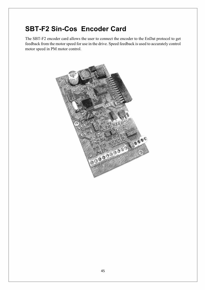
SBT-F2 Sin-Cos Encoder Card The SBT-F2 encoder card allows the user to connect the encoder to the EnDat protocol to get feedback from the motor speed for use in the drive. Speed feedback is used to accurately control motor speed in PM motor control.

46
v Connection Diagram
Figure 3 shows the encoder connections of the SBT-F2 model.
Figure 3 . SBT-F2 encoder card connection
A+
Supply+
-
A-
B+
B-
CLK+
CLK-
Aout +
Aout -
Bout +
Bout -
SBT-F2
Sheild
PG
A channel monitor signal
B channel monitor signal
Data+
Data -

47
v Appendix 3
Encoder card installation cautions Warning 1 : Be careful when connecting the power supply to the encoder.
Warning 2 : Avoid disconnecting the encoder card when the drive is on.
Warning 3 : Avoid connecting the encoder card when the drive is on.
Warning 4 : Make sure the shield wire is connected to the encoder card.

48
v Appendix 4
Encoder card faults Fault Name symbol Description Cause
Excessive Speed Deviation
The difference between the motor speed feedback and the reference speed is too high.
- The mechanical brake is not released. - The slope of the family c1 is too low. - Controller coefficients in c5 are not set correctly.
Encoder Fault
encoder card is not connected correctly or encoder is not working correctly.
The encoder card is not matched with encoder or there is a problem in encoder cable or encoder card is not connected correctly or encoder is damaged.
Encoder card OFC4 Encoder card is not working correctly
Encoder card is Not appropriate for this drive or encoder card is damaged.
Over Speed O5 The motor speed feedback exceeded the 60Hz
- Check the E1-04 parameter. - Check the drive speed parameter.

49
Address: No. 126, Noavari 12, Noavari St., Pardis Technology Park, Damavand Rd., Tehran, Iran
Tel: +98 21 76251431 +98 21 76250959 Fax: +98 21 76250298