Embed Size (px)
Citation preview

SolidWorks® Tutorial 4
CANDLESTICK
Tutorial 4: candlestick 2
CandlestickIn this tutorial you will make a simple container and a candlestick out of sheetmetal. You will learn aboutworking with sheet metal in SolidWorks. We will show you a couple of ways to create a product out ofsheetmetal and we will show you how to make a drawing in 2D.
Work plan First we will make a container. Look at the drawing below.
We will execute the following steps:
1. First, we will create the base. For this we will use an outside di-mension of 230 x 130.
2. After that, we will add four sides with a height of 30.
3. Finally we will look at the 2D drawing of the design.
Tutorial 4: candlestick 3
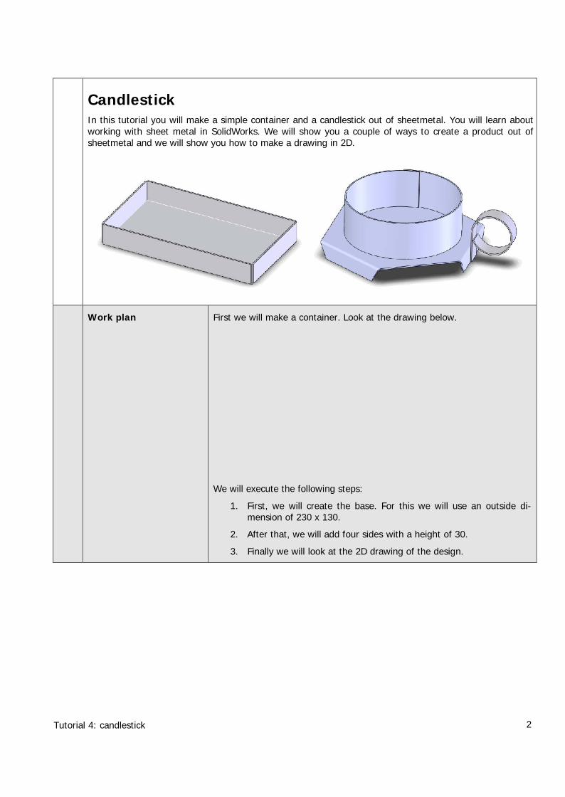
1 Start SolidWorks and opena new part.
2 Be sure that the buttonsyou need to work withSheetMetal are visible. Theeasiest way to access thesetools is to add them to theCommandManager.
1 Click on a tab in theCommandManagerwith the right mousebutton.
2 Click on ‘SheetMetal’ inthe menu that appears.
3 Select ‘Top Plane’ in theFeatureManager.
We will use this plane tocreate a sketch.
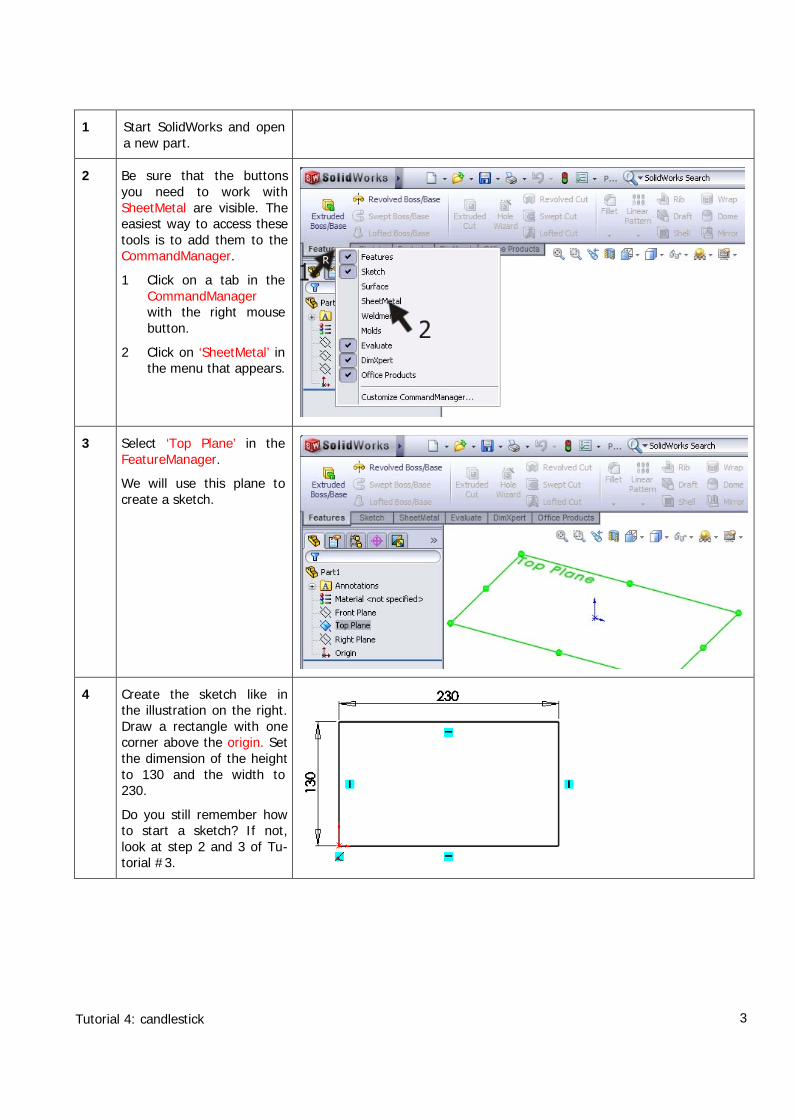
4 Create the sketch like inthe illustration on the right.Draw a rectangle with onecorner above the origin. Setthe dimension of the heightto 130 and the width to230.
Do you still remember howto start a sketch? If not,look at step 2 and 3 of Tu-torial #3.
Tutorial 4: candlestick 4
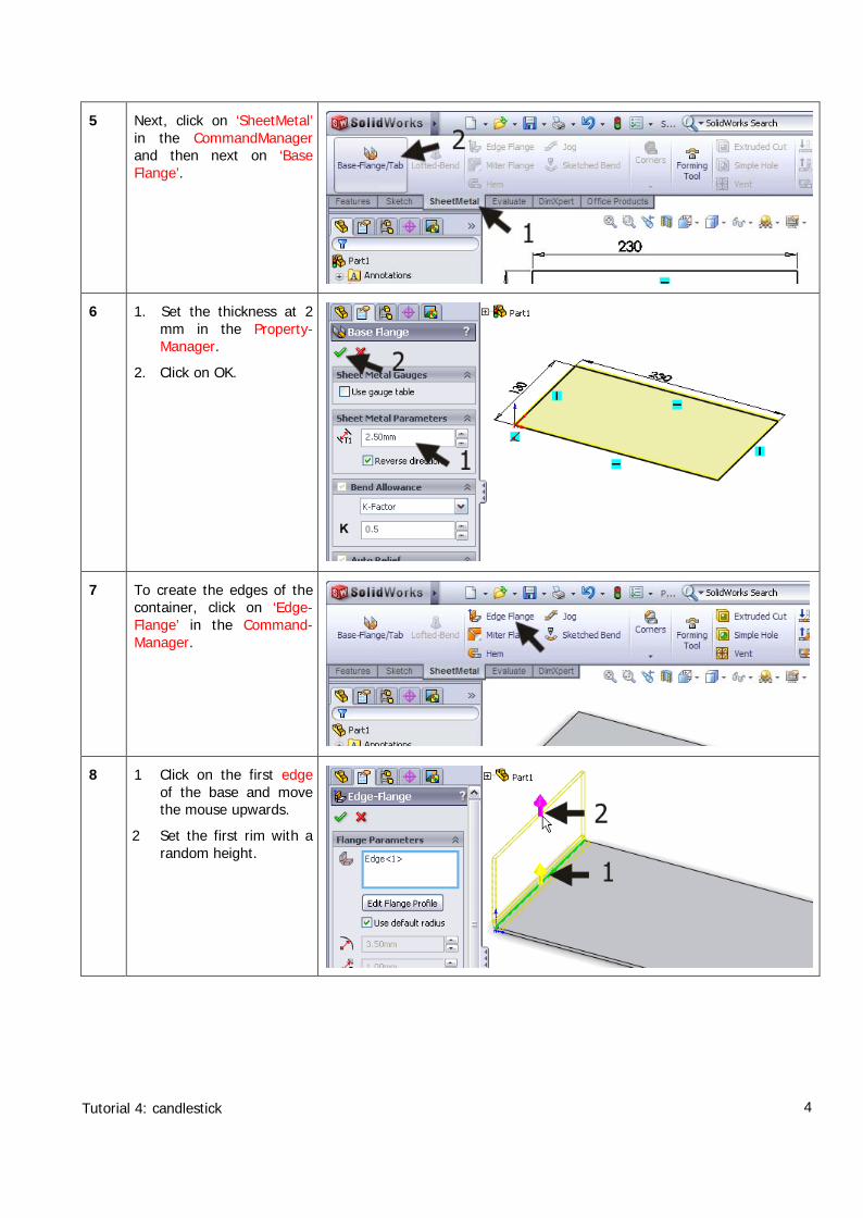
5 Next, click on ‘SheetMetal’in the CommandManagerand then next on ‘BaseFlange’.
6 1. Set the thickness at 2mm in the Property-Manager.
2. Click on OK.
7 To create the edges of thecontainer, click on ‘Edge-Flange’ in the Command-Manager.
8 1 Click on the first edgeof the base and movethe mouse upwards.
2 Set the first rim with arandom height.
Tutorial 4: candlestick 5
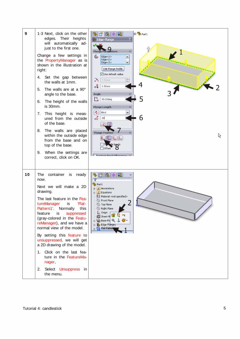
9 1-3 Next, click on the otheredges. Their heightswill automatically ad-just to the first one.
Change a few settings inthe PropertyManager as isshown in the illustration atright:
4. Set the gap betweenthe walls at 1mm.
5. The walls are at a 90°angle to the base.
6. The height of the wallsis 30mm.
7. This height is meas-ured from the outsideof the base.
8. The walls are placedwithin the outside edgefrom the base and ontop of the base.
9. When the settings arecorrect, click on OK.
10 The container is readynow.
Next we will make a 2Ddrawing.
The last feature in the Fea-tureManager is ‘Flat-Pattern1’. Normally thisfeature is suppressed(gray-colored in the Featu-reManager), and we have anormal view of the model.
By setting this feature tounsuppressed, we will geta 2D drawing of the model.
1. Click on the last fea-ture in the FeatureMa-nager,
2. Select Unsuppress inthe menu.
Tutorial 4: candlestick 6
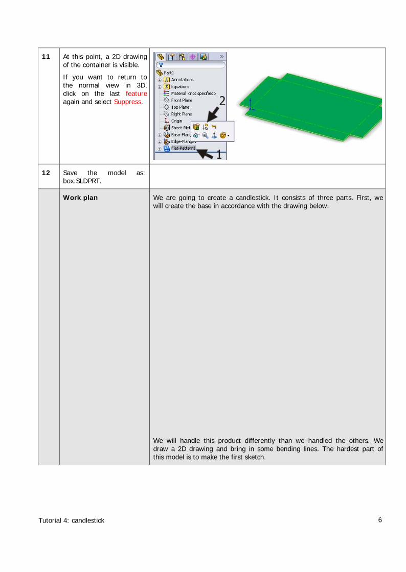
11 At this point, a 2D drawingof the container is visible.
If you want to return tothe normal view in 3D,click on the last featureagain and select Suppress.
12 Save the model as:box.SLDPRT.
Work plan We are going to create a candlestick. It consists of three parts. First, wewill create the base in accordance with the drawing below.
We will handle this product differently than we handled the others. Wedraw a 2D drawing and bring in some bending lines. The hardest part ofthis model is to make the first sketch.
Tutorial 4: candlestick 7
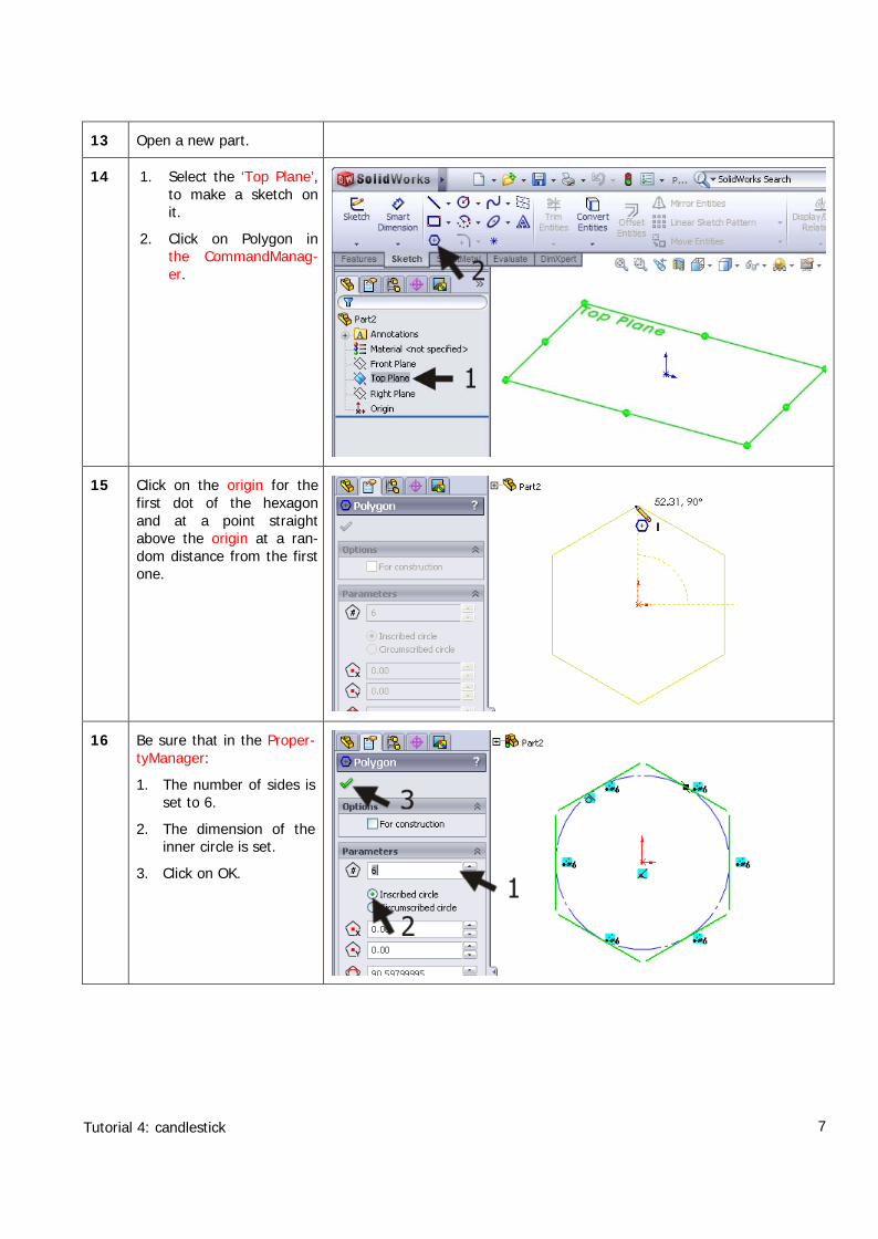
13 Open a new part.
14 1. Select the ‘Top Plane’,to make a sketch onit.
2. Click on Polygon inthe CommandManag-er.
15 Click on the origin for thefirst dot of the hexagonand at a point straightabove the origin at a ran-dom distance from the firstone.
16 Be sure that in the Proper-tyManager:
1. The number of sides isset to 6.
2. The dimension of theinner circle is set.
3. Click on OK.
Tutorial 4: candlestick 8
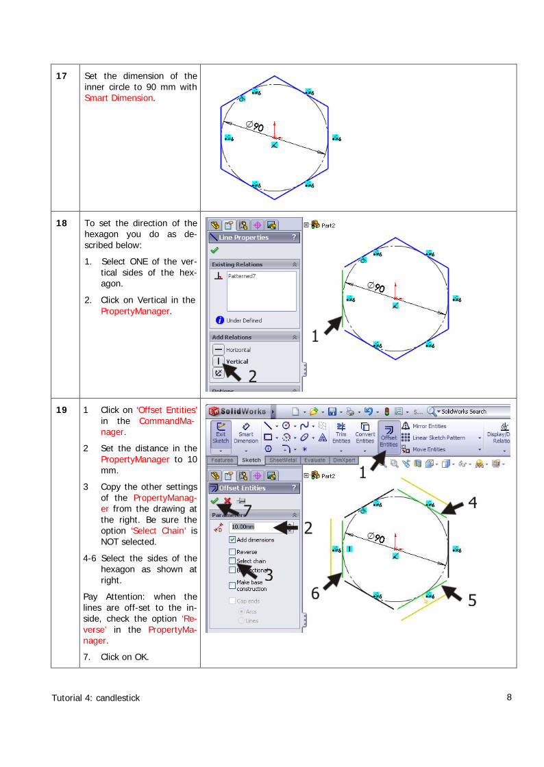
17 Set the dimension of theinner circle to 90 mm withSmart Dimension.
18 To set the direction of thehexagon you do as de-scribed below:
1. Select ONE of the ver-tical sides of the hex-agon.
2. Click on Vertical in thePropertyManager.
19 1 Click on ‘Offset Entities’in the CommandMa-nager.
2 Set the distance in thePropertyManager to 10mm.
3 Copy the other settingsof the PropertyManag-er from the drawing atthe right. Be sure theoption ‘Select Chain’ isNOT selected.
4-6 Select the sides of thehexagon as shown atright.
Pay Attention: when thelines are off-set to the in-side, check the option ‘Re-verse’ in the PropertyMa-nager.
7. Click on OK.
Tutorial 4: candlestick 9
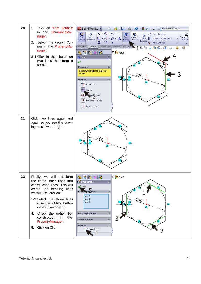
20 1. Click on ‘Trim Entities’in the CommandMa-nager.
2. Select the option Cor-ner in the PropertyMa-nager.
3-4 Click in the sketch ontwo lines that form acorner.
21 Click two lines again andagain so you see the draw-ing as shown at right.
22 Finally, we will transformthe three inner lines intoconstruction lines. This willcreate the bending lineswe will use later on.
1-3 Select the three lines(use the <Ctrl> buttonon your keyboard).
4. Check the option Forconstruction in thePropertyManager.
5. Click on OK.
Tutorial 4: candlestick 10
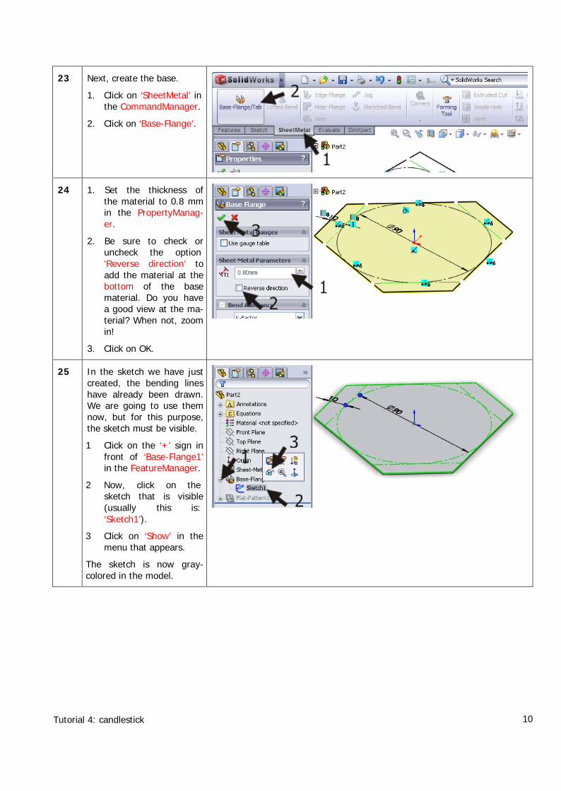
23 Next, create the base.
1. Click on ‘SheetMetal’ inthe CommandManager.
2. Click on ‘Base-Flange’.
24 1. Set the thickness ofthe material to 0.8 mmin the PropertyManag-er.
2. Be sure to check oruncheck the option‘Reverse direction’ toadd the material at thebottom of the basematerial. Do you havea good view at the ma-terial? When not, zoomin!
3. Click on OK.
25 In the sketch we have justcreated, the bending lineshave already been drawn.We are going to use themnow, but for this purpose,the sketch must be visible.
1 Click on the ‘+’ sign infront of ‘Base-Flange1’in the FeatureManager.
2 Now, click on thesketch that is visible(usually this is:‘Sketch1’).
3 Click on ‘Show’ in themenu that appears.
The sketch is now gray-colored in the model.
Tutorial 4: candlestick 11
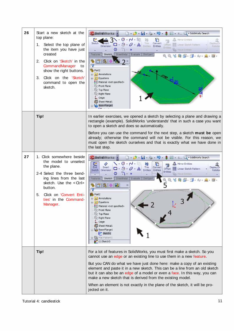
26 Start a new sketch at thetop plane:
1. Select the top plane ofthe item you have justcreated
2. Click on ‘Sketch’ in theCommandManager toshow the right buttons.
3. Click on the ‘Sketch’command to open thesketch.
Tip! In earlier exercises, we opened a sketch by selecting a plane and drawing arectangle (example). SolidWorks ‘understands’ that in such a case you wantto open a sketch and does so automatically.
Before you can use the command for the next step, a sketch must be openalready; otherwise the command will not be visible. For this reason, wemust open the sketch ourselves and that is exactly what we have done inthe last step.
27 1. Click somewhere besidethe model to unselectthe plane.
2-4 Select the three bend-ing lines from the lastsketch. Use the <Ctrl>button.
5. Click on ‘Convert Enti-ties’ in the Command-Manager.
Tip! For a lot of features in SolidWorks, you must first make a sketch. So youcannot use an edge or an existing line to use them in a new feature.
But you CAN do what we have just done here: make a copy of an existingelement and paste it in a new sketch. This can be a line from an old sketchbut it can also be an edge of a model or even a face. In this way, you canmake a new sketch that is derived from the existing model.
When an element is not exactly in the plane of the sketch, it will be pro-jected on it.
Tutorial 4: candlestick 12
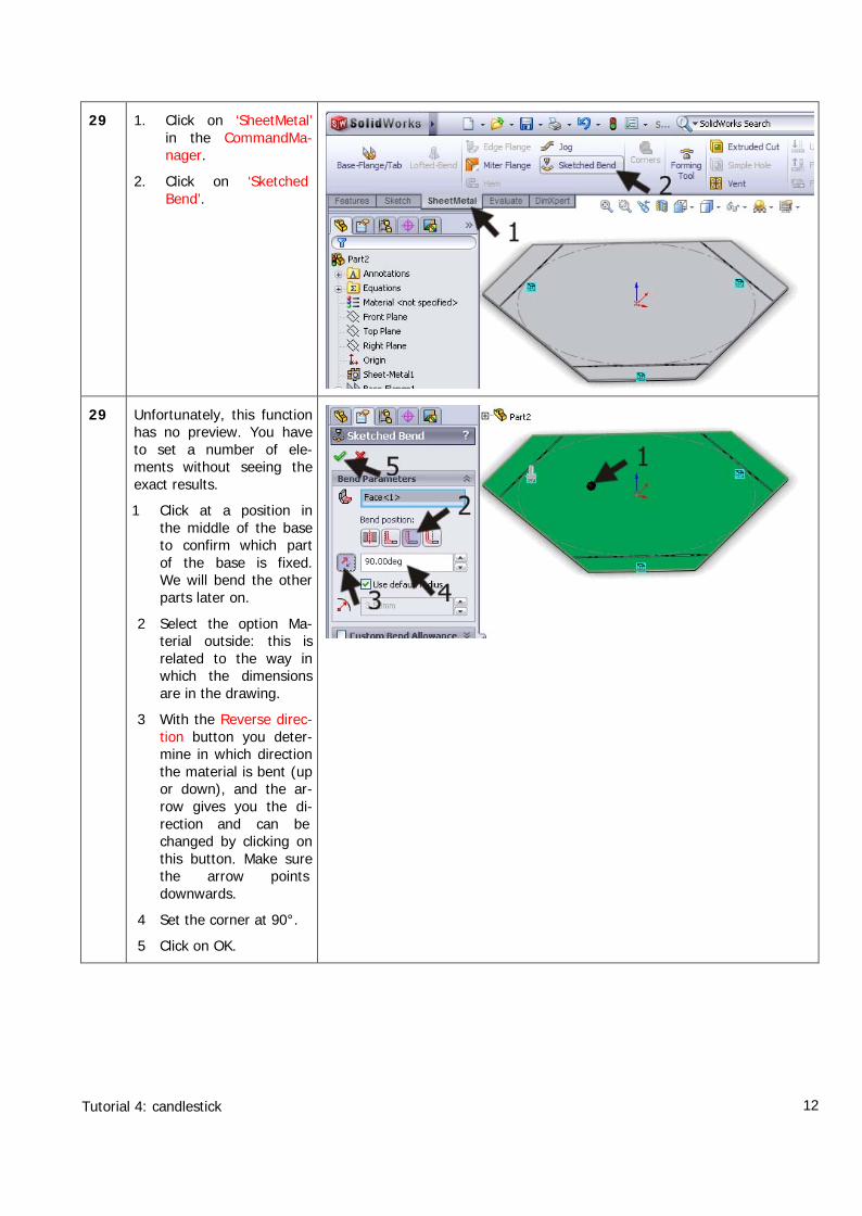
29 1. Click on ‘SheetMetal’in the CommandMa-nager.
2. Click on ‘SketchedBend’.
29 Unfortunately, this functionhas no preview. You haveto set a number of ele-ments without seeing theexact results.
1 Click at a position inthe middle of the baseto confirm which partof the base is fixed.We will bend the otherparts later on.
2 Select the option Ma-terial outside: this isrelated to the way inwhich the dimensionsare in the drawing.
3 With the Reverse direc-tion button you deter-mine in which directionthe material is bent (upor down), and the ar-row gives you the di-rection and can bechanged by clicking onthis button. Make surethe arrow pointsdownwards.
4 Set the corner at 90°.
5 Click on OK.
Tutorial 4: candlestick 13
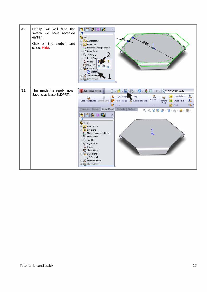
30 Finally, we will hide thesketch we have revealedearlier.
Click on the sketch, andselect Hide.
31 The model is ready now.Save is as base.SLDPRT.
Tutorial 4: candlestick 14
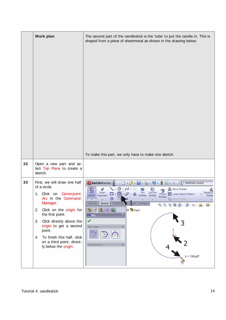
Work plan The second part of the candlestick is the ‘tube’ to put the candle in. This isshaped from a piece of sheetmetal as shown in the drawing below.
To make this part, we only have to make one sketch.
32 Open a new part and se-lect Top Plane to create asketch.
33 First, we will draw one halfof a circle.
1. Click on CenterpointArc in the Command-Manager.
2. Click on the origin forthe first point.
3. Click directly above theorigin to get a secondpoint.
4. To finish this half, clickon a third point, direct-ly below the origin.
Tutorial 4: candlestick 15
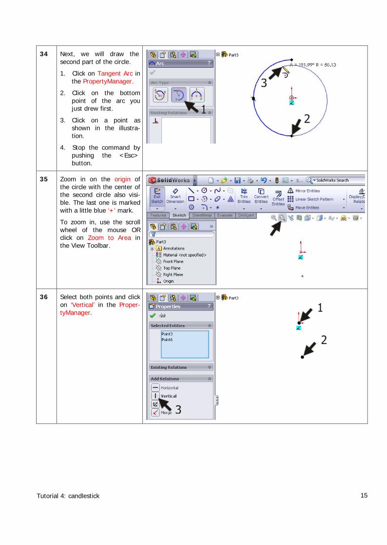
34 Next, we will draw thesecond part of the circle.
1. Click on Tangent Arc inthe PropertyManager.
2. Click on the bottompoint of the arc youjust drew first.
3. Click on a point asshown in the illustra-tion.
4. Stop the command bypushing the <Esc>button.
35 Zoom in on the origin ofthe circle with the center ofthe second circle also visi-ble. The last one is markedwith a little blue ‘+’ mark.
To zoom in, use the scrollwheel of the mouse ORclick on Zoom to Area inthe View Toolbar.
36 Select both points and clickon ‘Vertical’ in the Proper-tyManager.
Tutorial 4: candlestick 16
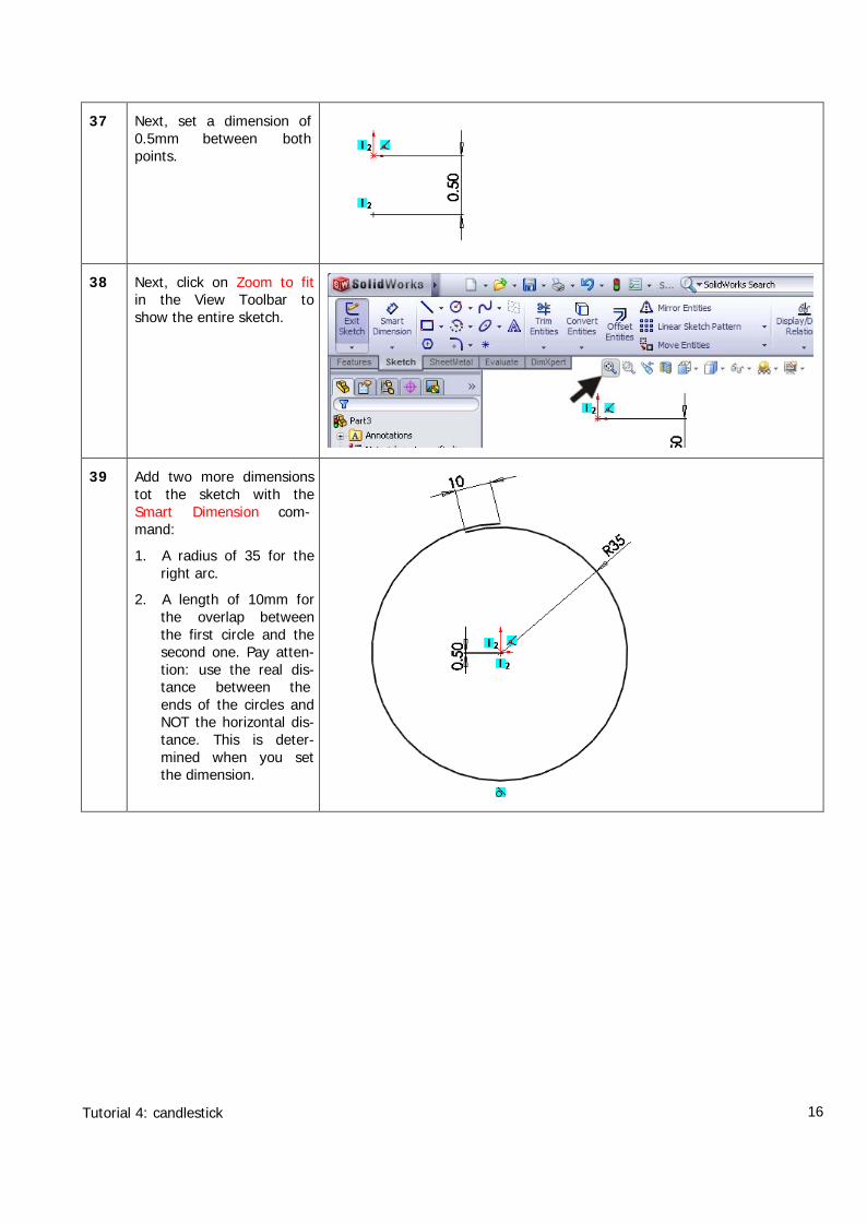
37 Next, set a dimension of0.5mm between bothpoints.
38 Next, click on Zoom to fitin the View Toolbar toshow the entire sketch.
39 Add two more dimensionstot the sketch with theSmart Dimension com-mand:
1. A radius of 35 for theright arc.
2. A length of 10mm forthe overlap betweenthe first circle and thesecond one. Pay atten-tion: use the real dis-tance between theends of the circles andNOT the horizontal dis-tance. This is deter-mined when you setthe dimension.
Tutorial 4: candlestick 17
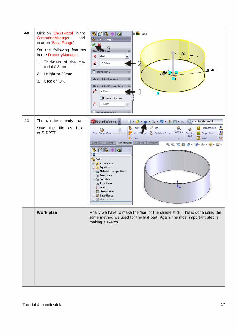
40 Click on ‘SheetMetal’ in theCommandManager andnext on ‘Base Flange’.
Set the following featuresin the PropertyManager:
1. Thickness of the ma-terial 0.8mm.
2. Height to 25mm.
3. Click on OK.
41 The cylinder is ready now.
Save the file as hold-er.SLDPRT.
Work plan Finally we have to make the ‘ear’ of the candle stick. This is done using thesame method we used for the last part. Again, the most important step ismaking a sketch.
Tutorial 4: candlestick 18
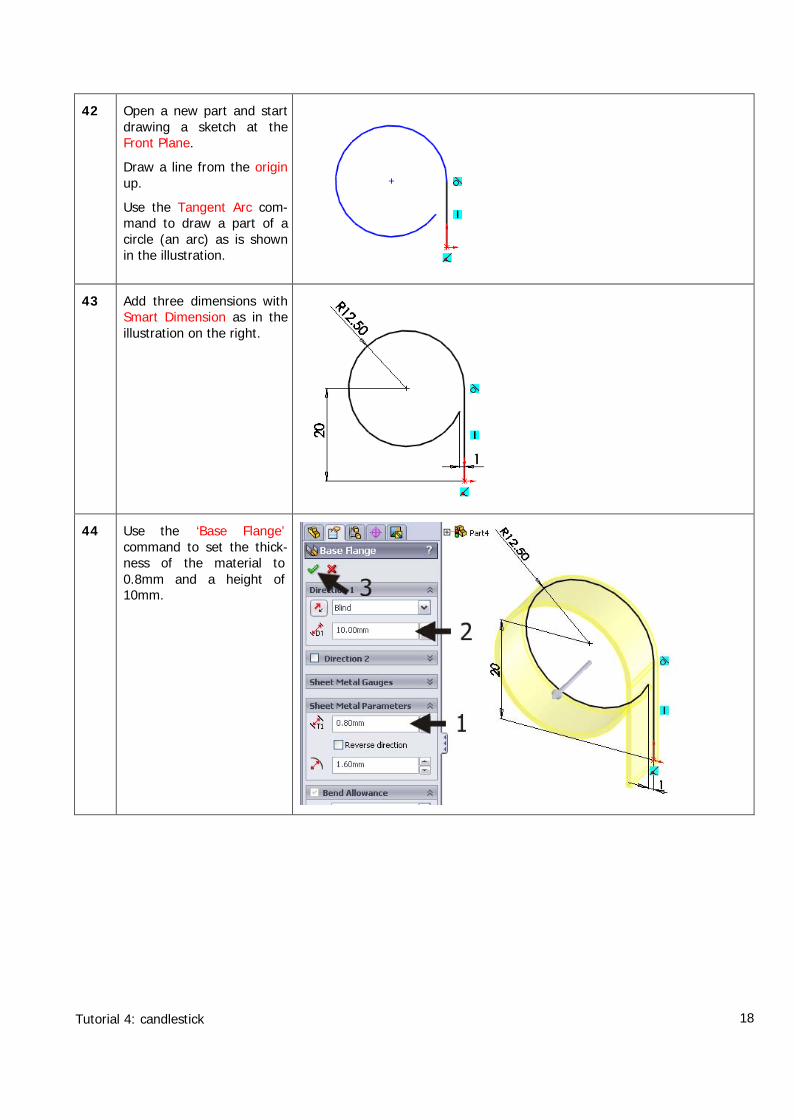
42 Open a new part and startdrawing a sketch at theFront Plane.
Draw a line from the originup.
Use the Tangent Arc com-mand to draw a part of acircle (an arc) as is shownin the illustration.
43 Add three dimensions withSmart Dimension as in theillustration on the right.
44 Use the ‘Base Flange’command to set the thick-ness of the material to0.8mm and a height of10mm.
Tutorial 4: candlestick 19
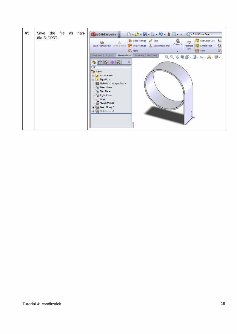
45 Save the file as han-dle.SLDPRT.
Tutorial 4: candlestick 20
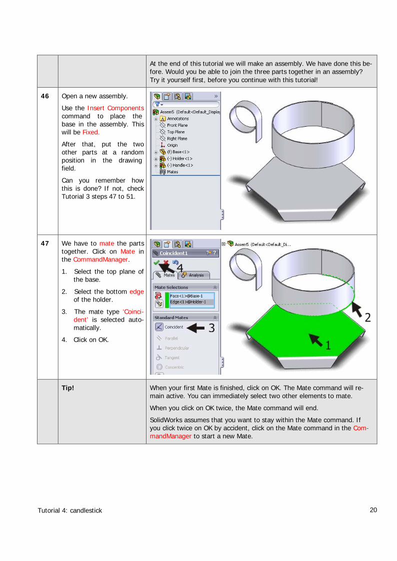
At the end of this tutorial we will make an assembly. We have done this be-fore. Would you be able to join the three parts together in an assembly?Try it yourself first, before you continue with this tutorial!
46 Open a new assembly.
Use the Insert Componentscommand to place thebase in the assembly. Thiswill be Fixed.
After that, put the twoother parts at a randomposition in the drawingfield.
Can you remember howthis is done? If not, checkTutorial 3 steps 47 to 51.
47 We have to mate the partstogether. Click on Mate inthe CommandManager.
1. Select the top plane ofthe base.
2. Select the bottom edgeof the holder.
3. The mate type ‘Coinci-dent’ is selected auto-matically.
4. Click on OK.
Tip! When your first Mate is finished, click on OK. The Mate command will re-main active. You can immediately select two other elements to mate.
When you click on OK twice, the Mate command will end.
SolidWorks assumes that you want to stay within the Mate command. Ifyou click twice on OK by accident, click on the Mate command in the Com-mandManager to start a new Mate.
Tutorial 4: candlestick 21
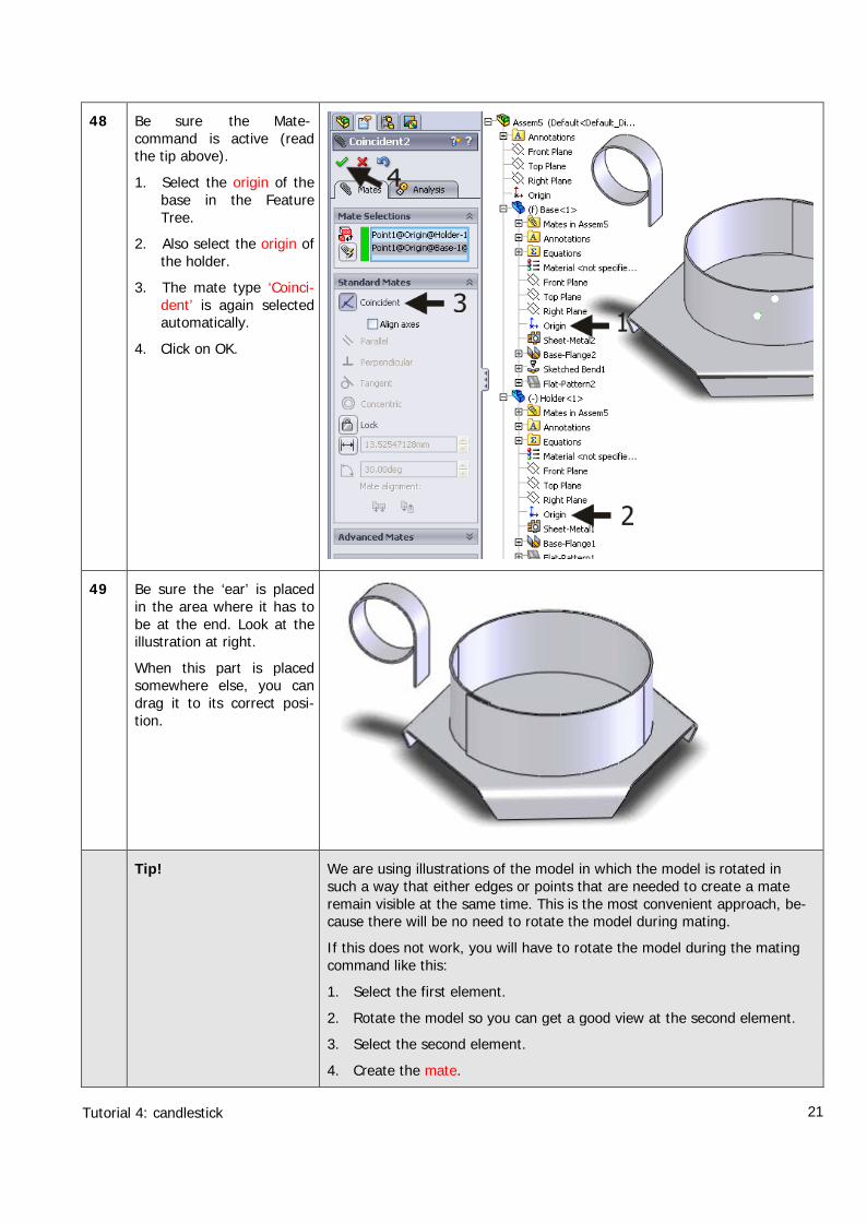
48 Be sure the Mate-command is active (readthe tip above).
1. Select the origin of thebase in the FeatureTree.
2. Also select the origin ofthe holder.
3. The mate type ‘Coinci-dent’ is again selectedautomatically.
4. Click on OK.
49 Be sure the ‘ear’ is placedin the area where it has tobe at the end. Look at theillustration at right.
When this part is placedsomewhere else, you candrag it to its correct posi-tion.
Tip! We are using illustrations of the model in which the model is rotated insuch a way that either edges or points that are needed to create a materemain visible at the same time. This is the most convenient approach, be-cause there will be no need to rotate the model during mating.
If this does not work, you will have to rotate the model during the matingcommand like this:
1. Select the first element.
2. Rotate the model so you can get a good view at the second element.
3. Select the second element.
4. Create the mate.
Tutorial 4: candlestick 22
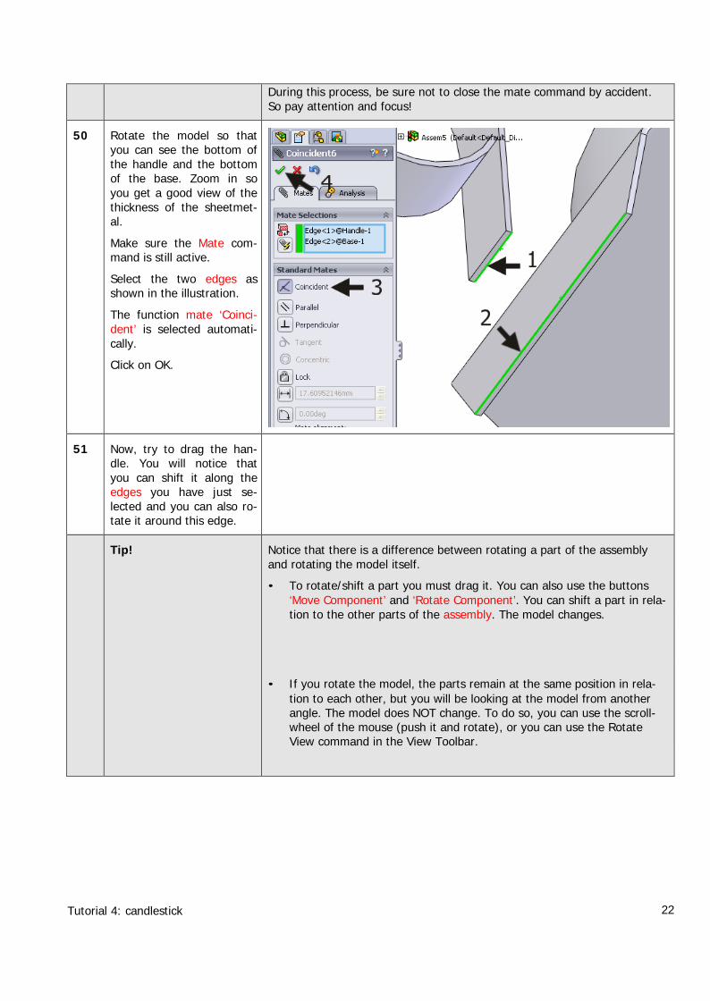
During this process, be sure not to close the mate command by accident.So pay attention and focus!
50 Rotate the model so thatyou can see the bottom ofthe handle and the bottomof the base. Zoom in soyou get a good view of thethickness of the sheetmet-al.
Make sure the Mate com-mand is still active.
Select the two edges asshown in the illustration.
The function mate ‘Coinci-dent’ is selected automati-cally.
Click on OK.
51 Now, try to drag the han-dle. You will notice thatyou can shift it along theedges you have just se-lected and you can also ro-tate it around this edge.
Tip! Notice that there is a difference between rotating a part of the assemblyand rotating the model itself.
• To rotate/shift a part you must drag it. You can also use the buttons‘Move Component’ and ‘Rotate Component’. You can shift a part in rela-tion to the other parts of the assembly. The model changes.
• If you rotate the model, the parts remain at the same position in rela-tion to each other, but you will be looking at the model from anotherangle. The model does NOT change. To do so, you can use the scroll-wheel of the mouse (push it and rotate), or you can use the RotateView command in the View Toolbar.
Tutorial 4: candlestick 23
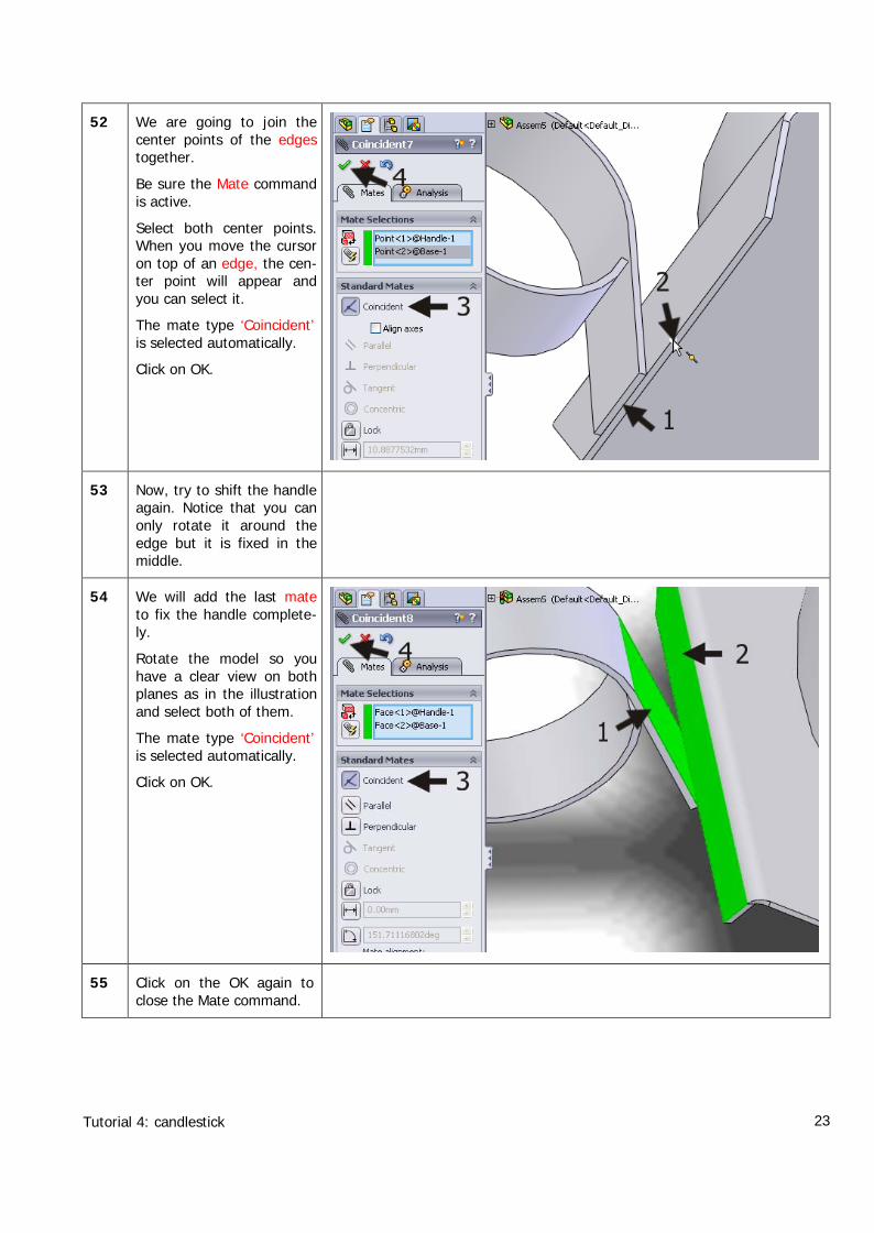
52 We are going to join thecenter points of the edgestogether.
Be sure the Mate commandis active.
Select both center points.When you move the cursoron top of an edge, the cen-ter point will appear andyou can select it.
The mate type ‘Coincident’is selected automatically.
Click on OK.
53 Now, try to shift the handleagain. Notice that you canonly rotate it around theedge but it is fixed in themiddle.
54 We will add the last mateto fix the handle complete-ly.
Rotate the model so youhave a clear view on bothplanes as in the illustrationand select both of them.
The mate type ‘Coincident’is selected automatically.
Click on OK.
55 Click on the OK again toclose the Mate command.
Tutorial 4: candlestick 24
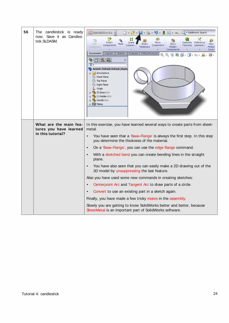
56 The candlestick is readynow. Save it as Candles-tick.SLDASM.
What are the main fea-tures you have learnedin this tutorial?
In this exercise, you have learned several ways to create parts from sheet-metal.
• You have seen that a ‘Base-Flange’ is always the first step. In this stepyou determine the thickness of the material.
• On a ‘Base-Flange’, you can use the edge flange command.
• With a sketched bend you can create bending lines in the straightplane.
• You have also seen that you can easily make a 2D drawing out of the3D model by unsuppressing the last feature.
Also you have used some new commands in creating sketches:
• Centerpoint Arc and Tangent Arc to draw parts of a circle.
• Convert to use an existing part in a sketch again.
Finally, you have made a few tricky mates in the assembly.
Slowly you are getting to know SolidWorks better and better, becauseSheetMetal is an important part of SolidWorks software.