Embed Size (px)
Citation preview

SolidWorks® Tutorial 3
MAGNETIC BLOCK

Tutorial 3: Magnetic Block 2
Magnetic BlockIn this exercise you will make a magnetic block. To do so, you will create a few parts, which you will as-semble. You will learn the following new applications in this tutorial:
• You will make two configurations of a part.
• You will weld the parts together.
• You will make holes using the Hole Wizard.
• You will use standardized parts from the Parts Library.
• You will assign different colors to different parts.
Work plan To make this assembly, you will have to make several parts. We will startwith a simple rectangular base with a thickness of 20mm per the drawingbelow.
We will perform the following steps:
1. Take a piece of material of 150x300x20.
2. Round off the four corners with a radius of 10 mm.
3. Drill four holes of Ø17.

Tutorial 3: Magnetic Block 3
1 Start SolidWorks and opena new part.
2 Click on ‘Top Plane’ in theFeatureManager (the leftcolumn of your screen inwhich all the parts of yourmodel are listed).
In this plane we will bemaking a sketch.
3 Click on ‘Sketch’ in theCommandManager to re-veal the correct buttonsand next on Rectangle todraw a rectangle.
4 1. Click on Center Rec-tangle in the Com-mandManager.
2. Click on the origin.
3. Click at a random pointas in the view at theright (#3) to draw arectangle.
5 Next use the commandSmart Dimension to deter-mine two dimensions atthe sides of the rectangle:150x300.
You have used Smart Di-mension before. Can youremember this? If not, lookit up again in Tutorial 2,steps 7 to 10.

Tutorial 3: Magnetic Block 4
6 1. Click on ‘Features’ inthe CommandManager.
2. Click on ‘ExtrudedBoss/Base’.
7 1 Set the thickness at20mm.
2 Click on OK.
8 Next, we will round off thecorners.
Click on ‘Fillet’ in theCommandManager.
The ‘Fillet’ command lookssimilar to the ‘Chamfer’command that we usedpreviously.

Tutorial 3: Magnetic Block 5
9 1. Make sure the option‘Full preview’ is se-lected.
2-5 Next select the fouredges you want toround off.
6. Set the radius at10mm.
7. Click on OK.
10 Next, select the top planeof the model just by click-ing it.
11 Click on ‘Sketch’ and nexton Rectangle to draw arectangle.

Tutorial 3: Magnetic Block 6
12 Click on the StandardViews button at the top ofthe screen and next onNormal To.
The model now rotates it-self to provide a straight-on view of the plane onwhich we are making thesketch.
It does not matter if themodel is positioned hori-zontally or vertically onyour screen.
13 4. Click on Center Rec-tangle in the Property-Manager.
5. Click on the origin.
6. Click at a random pointlike in the view at theright (#3) to draw arectangle.
14 Next, add two more di-mensions with the com-mand Smart Dimension:the horizontal dimension of240 and the vertical di-mension of 100.
15 Next click on ‘Exit Sketch’in the CommandManager.
The sketch remains visible,but turns grey.
Notice that we will make asketch, but do NOT make afeature of it. Later, you willsee how we will use sketchlike this.

Tutorial 3: Magnetic Block 7
16 First, click on ‘Features’ inthe CommandManager andnext on ‘Hole Wizard’.
17 You will have to set thefeatures of the holes in thePropertyManager.
1 Choose a ‘Hole Type’:choose Hole.
2 Check that the ‘Stan-dard’ is set at ‘ISO’.
3 Check that the ‘Type’ isset at ‘Drill sizes’.
4 Set the diameter atØ17mm.
5 Set the ‘End Condition’at ‘Through All’.
6 Click on the tab page‘Positions’.
18 Next, click on the four cor-ners of the rectangle youhave drawn before andthen click OK.
Tutorial 3: Magnetic Block 8
Tip!
The first part is ready now.
We could also have created the holes we just made with the Extruded Cutfeature. However, the Hole Wizard we just used is often very convenient,even more so if the holes you want to make area bit more complicated.Later on, we will see an example of this.
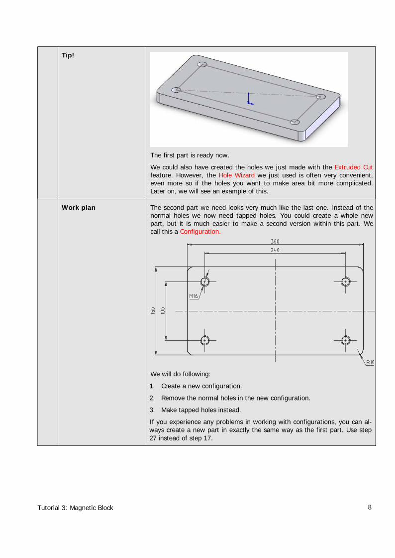
Work plan The second part we need looks very much like the last one. Instead of thenormal holes we now need tapped holes. You could create a whole newpart, but it is much easier to make a second version within this part. Wecall this a Configuration.
We will do following:
1. Create a new configuration.
2. Remove the normal holes in the new configuration.
3. Make tapped holes instead.
If you experience any problems in working with configurations, you can al-ways create a new part in exactly the same way as the first part. Use step27 instead of step 17.

Tutorial 3: Magnetic Block 9
19 Click on the third tab in theFeatureManager. Insteadof the FeatureManager orthe PropertyManager, theConfigurationManager nowappears.
20 There is only one configu-ration, named ‘Default[Part1]’. Click slowly on thename once or twice tochange the name.
21 Rename this item as:‘Holes’. Push the <Enter>key on your keyboard.
22 Next, make a new configu-ration:
1 Right-click on the topline of the list (‘Part1Configuration(s)’)
2 Select ‘Add Configura-tion’ in the menu.
23 Fill in the name of this con-figuration in the Property-Manager as ‘Taps’, andthen click OK.

Tutorial 3: Magnetic Block 10
24 Click on the first tab of theConfigurationManager togo to the FeatureManager.
Tip! At this point we have two configurations but only one is active: the one weare working in.
• In the ConfigurationManager you can recognize the active configurationbecause it is printed in black (check this at step 24).
• In the FeatureManager the name of the active configuration is at thetop of the list, behind the name of the created part (check this at step25).
25 Click on the last featureyou created (the holes).
Click on Suppress in themenu.
The holes now disappearfrom the model and areprinted grey in the Featu-reManager.
Tip! Instead of clicking on a feature with your left mouse button, you can alsouse the right mouse button. You will see a much more extended menu.
26 Click on ‘Hole Wizard’ inthe CommandManager.

Tutorial 3: Magnetic Block 11
27 Set the properties of theholes in the PropertyMa-nager.
1 Choose ‘Hole Type’:Tap.
2 Check that the ‘Stan-dard’ is set at ‘ISO’.
3 Check that the ‘Type’ isset at ‘Tapped hole’.
4 Set the dimension atM16.
5 Set the ‘End Condition’at ‘Through All’.
6 Click on the tab ‘Posi-tions’.
28 Click on the four corners ofthe rectangle to positionthe holes and then click onOK.
29 Now click on the sketchthat you have used to posi-tion the holes. Usually it isnamed ‘Sketch2’ or‘Sketch3’. The number canvary.
Click on Hide in the menuthat appears.
Tutorial 3: Magnetic Block 12
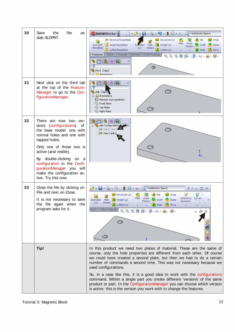
30 Save the file asslab.SLDPRT.
31 Next click on the third tabat the top of the Feature-Manager to go to the Con-figurationManager.
32 There are now two ver-sions (configurations) ofthe base model: one withnormal holes and one withtapped holes.
Only one of these two isactive (and visible).
By double-clicking on aconfiguration in the Confi-gurationManager you willmake the configuration ac-tive. Try this now.
33 Close the file by clicking onFile and next on Close.
It is not necessary to savethe file again when theprogram asks for it.
Tip! In this product we need two plates of material. These are the same ofcourse, only the hole properties are different from each other. Of coursewe could have created a second plate, but then we had to do a certainnumber of commands a second time. This was not necessary because weused configurations.
So, in a case like this, it is a good idea to work with the configurationscommand. Within a single part you create different ‘versions’ of the sameproduct or part. In the ConfigurationManager you can choose which versionis active: this is the version you work with to change the features.

Tutorial 3: Magnetic Block 13
Within every version you can make features invisible (suppressed) or visible(unsuppressed). By doing so, we create more than one version, and inevery version you have different features visible, like the normal holes orthe tapped holes in the two versions we have just completed.
Of course there are also many features which have to be visible in everyversion, like in the first part you have created. By changing a dimension inone version, the other versions will be changed automatically!
Work plan The next part we have to create is the bracket on top for the crane hook.
34 Open a new part, selectthe ‘Front Plane’ and createa sketch.
35 Click on ‘Sketch’ in theCommandManager next on‘Centerline’.
To create this part, we only have to make a sketch and extrude it.

Tutorial 3: Magnetic Block 14
36 Draw a centerline from theorigin straight up.
37 Next, draw a circle. Clickon the top end of the cen-terline. Move the mouseand click again to create acircle with a random ra-dius.
38 Next, draw two lines:
1 Click on Line in theCommandManager.
2 Click on the origin.
3 Move the mouse hori-zontally to the left andclick again to set asecond point (check theview on the right).
4 Move the mouse to-wards the circle. Movethe mouse over the cir-cle until the two yellowsicons appear as in theillustration on the right.When this is the case,you click to create a linewhich is in contact withthe circle.

Tutorial 3: Magnetic Block 15
39 Next, we will copy twolines.
Push the <Esc> key onyour keyboard to end theline command.
1. Select the first line.
2. Hold the <Ctrl> keyand select a secondline.
3. Keep the <Ctrl> keydown and select thecenterline.
4. Click on ‘Mirror Entities’in the CommandMa-nager.
40 The bottom part of the cir-cle has to be removed.
1 Click on ‘Trim Entities’in the CommandMa-nager.
2 Select the option ‘Trimto closest’ in the Pro-pertyManager.
3,4 Next, click on the twoparts of the circlewhich have to be re-moved.
41 Add three dimensions tothe sketch using SmartDimension. Check the illu-stration on the right.

Tutorial 3: Magnetic Block 16
42 Finally, draw another circleto make a hole with a di-mension of Ø24.
43 We can extrude the ma-terial of the sketch now.
1 Click on ‘Features’ inthe CommandManager.
2 Click on ‘ExtrudedBoss/Base’.
44 1 Select the option ‘MidPlane’ at Direction1 inthe PropertyManager.
2 Set the thickness at20mm.
3 Click on OK.

Tutorial 3: Magnetic Block 17
45 Save the file ascrane_hook.SLDPRT.
46 The parts are ready for theassembly.
1 Click on New in thetoolbar.
2 Select file type ‘Assem-bly’.
3 Click on OK.
47 We have closed the fileslab.SLDPRT. For this rea-son it is not in the list inthe PropertyManager.
Click on ‘Browse…’
Pay attention! Even whenthe file is not closed and isin the list, click on‘Browse…’. If you do notdo this, you will not beable to select the right con-figuration.
Tutorial 3: Magnetic Block 18
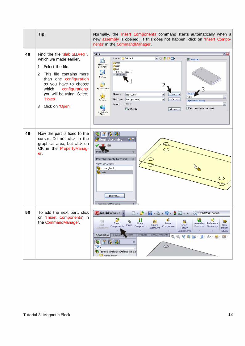
Tip! Normally, the Insert Components command starts automatically when anew assembly is opened. If this does not happen, click on ‘Insert Compo-nents’ in the CommandManager.
48 Find the file ‘slab.SLDPRT’,which we made earlier.
1 Select the file.
2 This file contains morethan one configurationso you have to choosewhich configurationsyou will be using. Select‘Holes’.
3 Click on ‘Open’.
49 Now the part is fixed to thecursor. Do not click in thegraphical area, but click onOK in the PropertyManag-er.
50 To add the next part, clickon ‘Insert Components’ inthe CommandManager.

Tutorial 3: Magnetic Block 19
51 1 Select the file‘Crane_hook’ in thelist,
2 Place the part at arandom position in theassembly.
Tip! Did you execute the previous steps correctly? You will notice that the basepart cannot be moved, while the crane hook can be moved around. This isbecause the first part you chose is Fixed. In the FeatureManager you canverify this because in front of the filename Slab is an ‘(f)’, and before theCrane_hook a ‘(-)’. The part with an (f) is a floating part and can bemoved around.
Be sure at all times that ONE part is Fixed; the other parts can be con-nected to this with the mate command.
You can make any part Fixed or Floating by clicking on it with the rightmouse buttons and choosing Fix or Float.
52 Click on ‘Mate’ in theCommandManager.

Tutorial 3: Magnetic Block 20
53 Click on the upper surfaceof the part.
54 Rotate the model so youget a clear view of the bot-tom side of the cranehook. Push the scroll-wheeland move your mouse torotate.
1 Click on the bottom ofthe crane hook.
The parts now move to-ward each other.
2 Click on OK.
55 The selection field in thePropertyManager is nowempty, and you can startwith the next mate imme-diately.
To center the crane hook,we use the standard planesFront Plane and RightPlane. You cannot selectthem in the model, howev-er, only in the FeatureMa-nager.
Because the PropertyMa-nager is now visible andnot the FeatureManager,you must use the Feature-Manager in the graphicalarea.
Click on the ‘+’ directly infront of the file name.

Tutorial 3: Magnetic Block 21
56 Next, click on the ‘+’ infront of both parts. Pay at-tention: after clicking onthe first ‘+’ the list ex-pands.
57 1 Next, select the ‘FrontPlane’ within the part‘Slab’
2 Also select the ‘FrontPlane’ within the part‘Crane_hook’.
3 Next, click on OK.

Tutorial 3: Magnetic Block 22
58 1 Select the ‘Right Plane’within the part ‘Slab’.
2 Also select the ‘RightPlane’ within the part‘Crane_hook’.
3 Click on OK.
4 Click on OK again toconfirm the mate, andagain to close downthe mate command.
59 Save the assembly as:crane_hook-complete.SLDASM.
60 We are going to weld theparts together.
1 Click on the arrow be-low the ‘Assembly Fea-tures’ in the Com-mandManager.
2 Click on the ‘Weld Sym-bol’.

Tutorial 3: Magnetic Block 23
61 Select the ‘Fillet’ type inthe menu that appears.This is a corner weld andthe most simple to add.
Then, click on ‘Next’.
62 We will make a curvedweld. Set the features as inthe illustration on the right,and click on ‘Next’.

Tutorial 3: Magnetic Block 24
63 Next, select the plane youwant to weld: the upperplane of the base and thevertical plane of the cranehook.
Click on ‘Next’.
64 The weld will be a separatepart in the assembly, andso it will be saved as aseparate file. This time, So-lidWorks determines thename of this ‘part’.
Click on ‘Finish’.
65 The weld is now made. So-lidWorks automaticallyadds a weld symbol.
Drag the symbol to a posi-tion beside the model.
If you want to change thesymbol, double-click on it.In one of the tutorials thatfollow we will get back tothis.

Tutorial 3: Magnetic Block 25
66 Repeat steps 60 to 65 tomake a weld at the otherside of the crane hook.
67 Save the assembly.
68 We are going to use thelast assembly in the mainassembly.
Click on ‘Make Assemblyfrom Part/Assembly’ in thetoolbar.
69 A new assembly appears inwhich the last assembly isadded automatically.
Click on OK.
70 Click on ‘Insert Compo-nents’ in the CommandMa-nager.

Tutorial 3: Magnetic Block 26
71 Click on ‘Browse…’ in thePropertyManager.
72 1. Select the file‘slab.SLDPRT’.
2. Select the configura-tion ‘Holes’.
3. Click on ‘Open’.
73 Click at a random positionto set the new base.
Click on OK.

Tutorial 3: Magnetic Block 27
74 Click on ‘Mate’ in theCommandManager.
75 Select the upper plane ofthe base first.
76 Next, rotate the model (bypushing the scroll-wheel ofthe mouse) and select thebottom plane of the cranehook.
Click on OK.

Tutorial 3: Magnetic Block 28
77 To make the next mate,you select the long sides ofboth parts and click on OK.
78 To make the final mate,you select the short sidesof both parts and click onOK.
Click on OK again to endthe Mate command
79 In the same way, addthree more similar partswith holes to the assembly.
The last part must be aplate with tapped holes. Sodo exactly the same thingagain, only now you selectthe configuration ‘Taps’when adding this part.
80 Save the assembly as‘Block_magnet.SLDASM’.

Tutorial 3: Magnetic Block 29
81 Next, we will add somecolors to our model.
1 Click on the first part(Crane_hook-complete) in the Featu-reManager.
2 Click on ‘Appearancecallout’ in the menuthat appears.
3 Click on Color in thebottom line.
82 First click on ‘Applychanges at assembly com-ponent level’ in the Proper-tyManager.
Select a color and click onOK. The whole part will becolored now.
83 Select another color foreach part of the magneticblock.
Tutorial 3: Magnetic Block 30
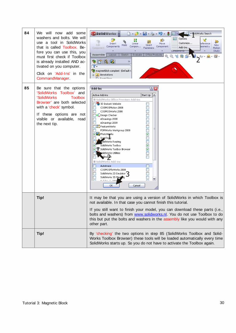
84 We will now add somewashers and bolts. We willuse a tool in SolidWorksthat is called Toolbox. Be-fore you can use this, youmust first check if Toolboxis already installed AND ac-tivated on you computer.
Click on ‘Add-Ins’ in theCommandManager.
85 Be sure that the options‘SolidWorks Toolbox’ and‘SolidWorks ToolboxBrowser’ are both selectedwith a ‘check’ symbol.
If these options are notvisible or available, readthe next tip.
Tip! It may be that you are using a version of SolidWorks in which Toolbox isnot available. In that case you cannot finish this tutorial.
If you still want to finish your model, you can download these parts (i.e.,bolts and washers) from www.solidworks.nl. You do not use Toolbox to dothis but put the bolts and washers in the assembly like you would with anyother part.
Tip! By ‘checking’ the two options in step 85 (SolidWorks Toolbox and Solid-Works Toolbox Browser) these tools will be loaded automatically every timeSolidWorks starts up. So you do not have to activate the Toolbox again.

Tutorial 3: Magnetic Block 31
86 Click on the symbol of theDesign Library in the TaskPane (at the right of thescreen).
87 The Task Pane unfolds it-self and you can see the‘Toolbox’ now. We aregoing to add some wash-ers.
Double-click the followingitems one after another:
1. ‘Toolbox’.
2. ‘ISO’.
3. ‘Washers’.
4. ‘Plain Washers’.
The available washers ap-pear in the lower part ofthe Task Pane.
5. Find the washer:‘Washer – ISO 7089Normal Grade A’.

Tutorial 3: Magnetic Block 32
88 Next, drag this washerform the Task Pane to yourmodel with the left mousebutton. As soon as thewasher is above one of theholes, it will find its way tothe right position. At thatmoment, release themouse button.
The washer may appeartoo small or too big, butthis does not matter at thispoint.
89 Change the setting of thewasher to ‘M16’ in the Pro-pertyManager, and click onOK.
90 The ring is now attached toyour mouse and you canput it on the other holes.After you have finishedplacing all the washers,click on Cancel.

Tutorial 3: Magnetic Block 33
91 Open the Task Pane againand go to:
1 ‘Toolbox’.
2 ‘ISO’.
3 ‘Bolts and Screws’.
4 ‘Hex Bolts and Screws’.
Select this bolt: ‘HexScrew Grade AB ISO4014’.
92 Again, drag this componentto one of the holes.
Pay attention: release themouse button when thecursor is above one of theholes.
This is important, becausewhen the cursor is abovethe plane, the bolt will bepositioned TOO LOW (atthe surface of the planeand NOT on top of thewasher).

Tutorial 3: Magnetic Block 34
93 In the PropertyManageryou can set the features ofthe bolt.
1. ‘Size’ (diameter) is‘M16’.
2. ‘Length’ of the bolt is‘120mm’.
3. ‘Thread Length’ of thethread is ‘38mm’.
4. ‘Thread Display’ (thethread is displayed as)is ‘Cosmetic’.
5. Click on OK.
94 Now the bolt is attached tothe cursor, so you can putin the other holes too. Payattention to click on thewasher and NOT in thehole!

Tutorial 3: Magnetic Block 35
95 The magnetic block isready now. Save the as-sembly.
What are the main fea-tures you have learnedin this tutorial?
In this exercise we have executed many new commands.
• You have created parts from a symmetrical axis.
• You have use a number of new sketch-tools, like Mirror and Trim.
• You have used the Hole Wizard to make complicated holes.
• You have made a welded connection in the assembly.
• You have colored part
• You have used standard parts from the Toolbox.
You have reached the next level in SolidWorks, and you learned some po-werful tools.