Embed Size (px)
Citation preview

1
Solid-state Timer
H3YNMiniature Timer with Multiple Time Ranges and Multiple Operating Modes
• Multiple operating modes include ON-delay, interval, flicker OFF start, or flicker ON start.
• Multiple time ranges from 0.1 s to 10 min or 1 min to 10 hr• Minimizes stock: User selectable time range and mode by
DIP switches.• Pin configuration compatible with MY Power Relay.• Conforms to EN 61812-1 and IEC 60664-1 for Low
Voltage, and EMC Directives.
Ordering InformationList of ModelsSpecify both the model number and supply voltage when ordering. Example: H3YN-2 DC24
Note: Sockets and Hold-down Clips are not included with the H3YN. They must be ordered separately. *1. Use the H3YN-4 or H3YN-41 Series when switching micro loads, and use the H3YN-4-Z or H3YN-41-Z Series when switching even smaller
loads.*2. Only models with 24 VDC power supply are available.
Accessories (Order Separately)Adapter, Mounting Plate, Clip
Note: For details, refer to Precautions for H3Y-series Timers on page 14.
Socket
Note: 1. Cannot be used with the H3Y-@-0 (PCB terminals).2. The PYFA-E has a finger-protection structure. Round crimp terminals cannot be used. Use forked crimp
terminals.3. For details, refer to Precautions for H3Y-series Timers on page 14.
For the most recent information on models that have been certified for safety standards, refer to your OMRON website.
LR
Refer to Safety Precautions on page 14.
Supply voltage Time-limit contact Short-time range model(0.1 s to 10 min)
Long-time range model(0.1 min to 10 h)
24, 100 to 120, 200 to 230 VAC; 12, 24, 48, 100 to 110, 125 VDC
DPDT H3YN-2 H3YN-214PDT H3YN-4 *1 H3YN-41 *1
24 VDC 4PDT (Twin contacts) H3YN-4-Z *1, *2 H3YN-41-Z *1, *2
Name/specification ModelFlush mounting adapter Y92F-78
Mounting Plate for SocketFor 1 Socket PYP-1For 18 Sockets PYP-18
ClipFor PYF@A Y92H-3For PY@ and PYF@M Y92H-4
Timer Square SocketsContact Model Pin Connection Terminal Model
DPDT H3YN-2@ 8-pin
Front Connecting
DIN track mounting PYF08ADIN track mounting (Finger-safe type) PYF08A-E
Screw mounting PYF08F
Back ConnectingSolder terminal PY08PCB terminal PY08-02
4PDT H3YN-4@ 14-pin
Front ConnectingDIN track mounting PYF14ADIN track mounting (Finger-safe type) PYF14A-E
Back ConnectingSolder terminal PY14PCB terminal PY14-02
H3YN
2
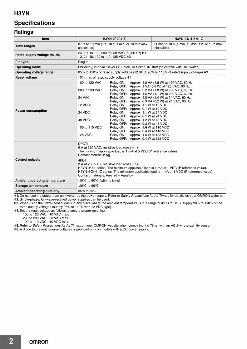
SpecificationsRatings
*1. Do not use the output from an inverter as the power supply. Refer to Safety Precautions for All Timers for details on your OMRON website.*2. Single-phase, full-wave-rectified power supplies can be used.*3. When using the H3YN continuously in any place where the ambient temperature is in a range of 45°C to 50°C, supply 90% to 110% of the
rated supply voltages (supply 95% to 110% with 12 VDC type).*4. Set the reset voltage as follows to ensure proper resetting.
100 to 120 VAC: 10 VAC max.200 to 230 VAC: 20 VAC max.100 to 110 VDC: 10 VDC max.
*5. Refer to Safety Precautions for All Timers on your OMRON website when combining the Timer with an AC 2-wire proximity sensor.*6. A diode to prevent reverse voltages is provided only on models with a DC power supply.
Item H3YN-2/-4/-4-Z H3YN-21/-41/-41-Z
Time ranges 0.1 s to 10 min (1 s, 10 s, 1 min, or 10 min max. selectable)
0.1 min to 10 h (1 min, 10 min, 1 h, or 10 h max. selectable)
Rated supply voltage *5, *6 24, 100 to 120, 200 to 230 VAC (50/60 Hz) *112, 24, 48, 100 to 110, 125 VDC *2
Pin type Plug-in
Operating mode ON-delay, interval, flicker OFF start, or flicker ON start (selectable with DIP switch)
Operating voltage range 85% to 110% of rated supply voltage (12 VDC: 90% to 110% of rated supply voltage) *3
Reset voltage 10% min. of rated supply voltage *4
Power consumption
100 to 120 VAC: Relay ON: Approx. 1.8 VA (1.6 W) at 120 VAC, 60 HzRelay OFF: Approx. 1 VA (0.6 W) at 120 VAC, 60 Hz
200 to 230 VAC: Relay ON: Approx. 2.2 VA (1.8 W) at 230 VAC, 60 HzRelay OFF: Approx. 1.5 VA (1.1 W) at 230 VAC, 60 Hz
24 VAC: Relay ON: Approx. 1.8 VA (1.4 W) at 24 VAC, 60 HzRelay OFF: Approx. 0.3 VA (0.2 W) at 24 VAC, 60 Hz
12 VDC: Relay ON: Approx. 1.1 W at 12 VDCRelay OFF: Approx. 0.1 W at 12 VDC
24 VDC: Relay ON: Approx. 1.1 W at 24 VDCRelay OFF: Approx. 0.1 W at 24 VDC
48 VDC: Relay ON: Approx. 1.2 W at 48 VDCRelay OFF: Approx. 0.3 W at 48 VDC
100 to 110 VDC: Relay ON: Approx. 1.6 W at 110 VDCRelay OFF: Approx. 0.4 W at 110 VDC
125 VDC: Relay ON: Approx. 1.6 W at 125 VDCRelay OFF: Approx. 0.4 W at 125 VDC
Control outputs
DPDT:5 A at 250 VAC, resistive load (cosφ = 1)The minimum applicable load is 1 mA at 5 VDC (P reference value).Contact materials: Ag
4PDT:3 A at 250 VAC, resistive load (cosφ = 1)H3YN-4/-41 series: The minimum applicable load is 1 mA at 1 VDC (P reference value).H3YN-4-Z/-41-Z series: The minimum applicable load is 1 mA at 1 VDC (P reference value).Contact materials: Au-clad + Ag-alloy
Ambient operating temperature -10°C to 50°C (with no icing)
Storage temperature -25°C to 65°CAmbient operating humidity 35% to 85%

H3YN
3
Characteristics
*1. Terminal screw sections are excluded.*2. The destructive shock resistance test was performed on the Timer.*3. Refer to the Life-test Curve.*4. Overvoltage category II.
Item H3YN-2/-21/-4/-41Accuracy of operating time ±1% FS max. (1 s range: ±1%±10 ms max.)
Setting error ±10%±50 ms FS max.
Reset time Min. power-opening time: 0.1 s max. (including halfway reset)
Influence of voltage ±2% FS max.
Influence of temperature ±2% FS max.
Insulation resistance 100 MΩ min. (at 500 VDC)
Dielectric strength
2,000 VAC, 50/60 Hz for 1 min (between current-carrying terminals and exposed non-current-carrying metal parts) *1
2,000 VAC, 50/60 Hz for 1 min (between operating power circuit and control output) 2,000 VAC, 50/60 Hz for 1 min (between different pole contacts; 2-pole model) 1,500 VAC, 50/60 Hz for 1 min (between different pole contacts; 4-pole model)1,000 VAC, 50/60 Hz for 1 min (between non-continuous contacts)
Vibration resistance Destruction: 10 to 55 Hz, 0.75-mm single amplitude for 1 h each in 3 directionsMalfunction: 10 to 55 Hz, 0.5-mm single amplitude for 10 min each in 3 directions
Shock resistance Destruction: 1,000 m/s2 *2Malfunction: 100 m/s2
Life expectancy
Mechanical: 10,000,000 operations min. (under no load at 1,800 operations/h)Electrical: DPDT:
500,000 operations min. (5 A at 250 VAC, resistive load at 1,800 operations/h)4PDT:200,000 operations min. (H3YN-4-Z/-41-Z: 100,000 operations min.)(3 A at 250 VAC, resistive load at 1,800 operations/h) *3
Impulse withstand voltage
Between power terminals:3 kV for 100 to 120 VAC, 200 to 230 VAC, 100 to 110 VDC, 125 VDC1 kV for 12 VDC, 24 VDC, 48 VDC, 24 VACBetween exposed non-current-carrying metal parts:4.5 kV for 100 to 120 VAC, 200 to 230 VAC, 100 to 110 VDC, 125 VDC1.5 kV for 12 VDC, 24 VDC, 48 VDC, 24 VAC
Noise immunity ±1.5 kV, square-wave noise by noise simulator (pulse width: 100 ns/1 μs, 1-ns rise)
Static immunity Destruction: 8 kVMalfunction: 4 kV
Degree of protection IP40
Weight Approx. 50 g
EMC
(EMI) EN 61812-1Emission Enclosure: EN 55011 Group 1 class AEmission AC Mains: EN 55011 Group 1 class A(EMS) EN 61812-1Immunity ESD: IEC 61000-4-2Immunity RF-interference: IEC 61000-4-3Immunity Burst: IEC 61000-4-4Immunity Surge: IEC 61000-4-5Immunity Conducted Disturbance: IEC 61000-4-6Immunity Voltage Dip/Interruption: IEC 61000-4-11
Approved standardsUL 508, CSA C22.2 No. 14, Lloyds, CCCConforms to EN 61812-1 and IEC 60664-1. (2.5 kV/2 for H3YN-2/-21, 2.5 kV/1 for H3YN-4/-41, H3YN-4-Z/-41-Z) *4

H3YN
4
Life-test Curve (Reference Value)
500
100
50
20
500
100
50
20
500
100
50
20
500
100
50
20
500
10050
106
H3YN-2/-21
H3YN-4/-41
H3YN-4-Z/-41-Z
Sw
itchi
ng o
pera
tions
(x
104 )
Load current (A)
Sw
itchi
ng o
pera
tions
(x
104 )
Load current (A)
Sw
itchi
ng o
pera
tions
(x
104 )
Load current (A)
Sw
itchi
ng o
pera
tions
(x
104 )
Load current (A)
Sw
itchi
ng o
pera
tions
(x
104 )
Load current (A)
250 VAC, resistive load
250 VAC, cosφ = 124 VDC, cosφ = 1
Reference: A maximum current of 0.6 A can be switched at 125 VDC (cosφ = 1). Maximum current of 0.2 A can be switched if L/R is 7 ms. In both cases, a life of 100,000 operations can be expected.
The minimum applicable load is 1 mA at 5 VDC (P reference value)
250 VAC, cosφ = 0.424 VDC, L/R = 7 ms
250 VAC, cosφ = 124 VDC, cosφ = 1
Reference: A maximum current of 0.5 A can be switched at 125 VDC (cosφ = 1). Maximum current of 0.2 A can be switched if L/R is 7 ms. In both cases, a life of 100,000 operations can be expected.
The minimum applicable load is 1 mA at 1 VDC (P reference value)
250 VAC, cosφ = 0.424 VDC, L/R = 7 ms
24 VDC, resistive load
Reference: A maximum current of 0.5 A can be switched at 125 VDC (cosφ = 1). Maximum current of 0.2 A can be switched if L/R is 7 ms. In both cases, a life of 100,000 operations can be expected.
The minimum applicable load is 0.1 mA at 1 VDC (P reference value).

H3YN
5
ConnectionsConnection
Pulse OperationA pulse output for a certain period can be obtained with a random external input signal.Use the H3YN in interval mode as shown in the following timing charts.
Mode Terminals
Pulse operationPower supply between 9 and 14Short-circuit between 5 and 13Input signal between 9 and 13
Operating mode; interval and all other modes Power supply between 13 and 14
UP PW
H3YN-2/-21
DIN Notation DIN Notation
UP PW
Timer circuit
Timer circuit
H3YN-4/-41 H3YN-4-Z/-41-Z
(Bottom View) (Bottom View)
H3YN-2/-21
External input
Power (9-14)
Power (9-14)
External input
H3YN-4/-41H3YN-4-Z/-41-Z
Timer circuit
Timer circuit
External short circuit (5-13)
External input (9-13)
Time limit contact NO (12-8)
Time limit contact NC (12-4)
Run/Power indicator (PW)Output indicator (UP)
50 ms min.
Note: t: Set timeRt: Reset time
External short circuit (5-13)
External input (9-13)
Time limit contact NO (10-6, 11-7, 12-8)
Time limit contact NC (10-2, 11-3, 12-4)
Run/Power indicator (PW)Output indicator (UP)
50 ms min.
Note: t: Set timeRt: Reset time
!CautionBe careful when connecting wires.

H3YN
6
Nomenclature
Dimensions (Unit: mm)
Timers
Run/Power Indicator (Green)(Lit: Power ON)
Output Indicator (Orange)(Lit: Output ON)
Main Dial
Set the desired time according to time range selectable by DIP switch.
6.4(63.0)
H3YN-2/-21 Front Mounting
Fourteen, 3 × 1.2 elliptic holes
28 max.
21.5 max.
28 max.
21.5 max.
Eight, 3 × 1.2 elliptic holes
H3YN-4/-41 Front Mounting H3YN-4-Z/-41-Z
Mounting Holes
Eight, 1.3-dia. holes
Pin 1
Mounting Holes
Fourteen, 1.3-dia. holes
Pin 1

H3YN
7
OperationDIP Switch SettingsThe 1-s range and ON-delay mode for H3YN-2/-4/-4-Z, the 1-min range and ON-delay mode for H3YN-21/-41/-41-Z are factory-set before shipping.
Time Ranges
Note: The top two DIP switch pins are used to select the time ranges.
Operating Modes
Note: The bottom two DIP switch pins are used to select the operating mode.
Model Time range Time setting range Setting Factory-set
H3YN-2, H3YN-4H3YN-4-Z
1 s 0.1 to 1 s Yes
10 s 1 to 10 s No
1 min 0.1 to 1 min No
10 min 1 to 10 min No
H3YN-21, H3YN-41H3YN-41-Z
1 min 0.1 to 1 min Yes
10 min 1 to 10 min No
1 h 0.1 to 1 h No
10 h 1 to 10 h No
Operating mode Setting Factory-set
ON-delay Yes
Interval No
Flicker OFF-start No
Flicker ON-start No

H3YN
8
Timing Chart
Note: t: Set timeRt: Reset time
Operating modeTiming chart
H3YN-2/-21 H3YN-4/-41
ON-delay
Power
Output
Power (13-14)
Time limit contact NC (9-1, 12-4)
Time limit contact NO (9-5, 12-8)
Run/Power indicator (PW)
Output indicator
Power (13-14)
Time limit contact NC (9-1, 10-2, 11-3, 12-4)Time limit contact NO (9-5, 10-6, 11-7, 12-8)
Run/Power indicator (PW)Output indicator (UP)
Interval
Power
Output
Power (13-14)
Time limit contact NC (9-1, 12-4)
Time limit contact NO (9-5, 12-8)
Run/Power indicator (PW)Output indicator (UP)
Power (13-14)
Time limit contact NC (9-1, 10-2, 11-3, 12-4)Time limit contact NO (9-5, 10-6, 11-7, 12-8)Run/Power indicator (PW)
Output indicator (UP)
Flicker OFF-start
Power
Output
Power (13-14)
Time limit contact NC (9-1, 12-4)
Time limit contact NO (9-5, 12-8)
Run/Power indicator (PW)
Output indicator (UP)
Power (13-14)
Time limit contact NC (9-1, 10-2, 11-3, 12-4)Time limit contact NO (9-5, 10-6, 11-7, 12-8)Run/Power indicator (PW)Output indicator (UP)
Flicker ON-start
Power
Output
Power (13-14)
Time limit contact NC (9-1, 12-4)
Time limit contact NO (9-5, 12-8)
Run/Power indicator (PW)
Output indicator (UP)
Power (13-14)
Time limit contact NC (9-1, 10-2, 11-3, 12-4)Time limit contact NO (9-5, 10-6, 11-7, 12-8)Run/Power indicator (PW)Output indicator (UP)

H3Y Series
9
Precautions for H3Y-series TimersFlush Mounting Adapter
Note: 1. Push the H3Y in until the Adaptor (Y92F-78) hooks engage with its rear panel.2. Do not round the corners of the cutout on the rear panel surface, otherwise the Adaptor (Y92F-78) tabs may not engage properly.
Mounting Height
33.5
27.1 48.5
31.5
25.13
3
525.2+0.2−0
31.6+0.2−0
R0.5 max.
Panel Cutout
Y92F-78
Panel thickness 1 to 3 mm
PY08 (PY14)
PY08 (PY14 *1) PY08QN (PY14QN *1)
PYF08A (PYF14A)
PYF08A/PYF08A-N/PYF08A-E (PYF14A/PYF14A-N/PYF14A-E *1)
H3YN Series
H3YN Series
H3YN Series
PY08QN (PY14QN)
*1. Models in parentheses are Connecting Sockets to the H3YN-4/-41 or H3YN-4-Z/-41-Z.
Connecting Sockets (Sold Separately)H3Y/H3YN SeriesUse one of the following Connecting Sockets: PYF@A, PYF@M, PY@, PY@-02, or PY@QN(2)(-Y3).(@ = 08 or 14)
H3Y Series
10
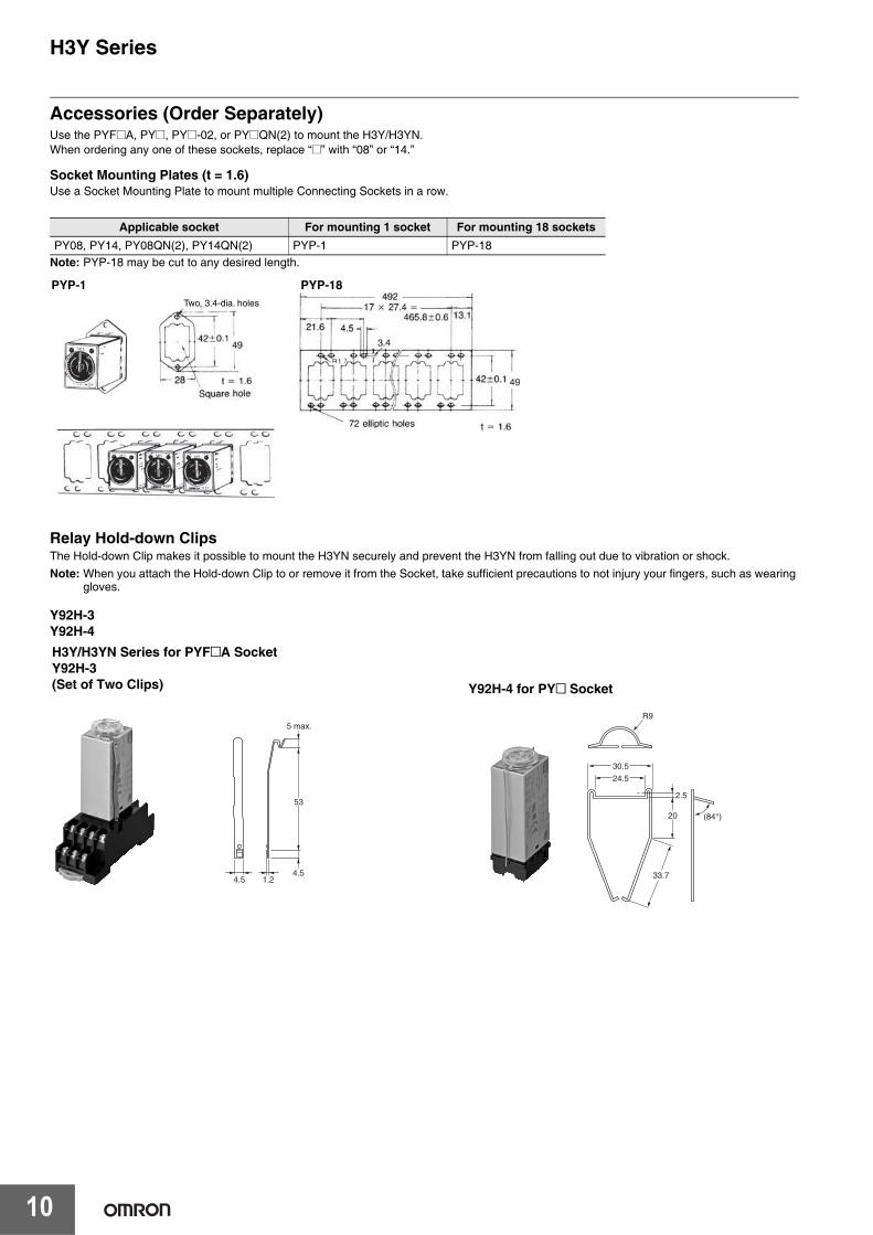
Accessories (Order Separately)Use the PYF@A, PY@, PY@-02, or PY@QN(2) to mount the H3Y/H3YN. When ordering any one of these sockets, replace “@” with “08” or “14.”
Socket Mounting Plates (t = 1.6)Use a Socket Mounting Plate to mount multiple Connecting Sockets in a row.
Note: PYP-18 may be cut to any desired length.
Relay Hold-down ClipsThe Hold-down Clip makes it possible to mount the H3YN securely and prevent the H3YN from falling out due to vibration or shock.Note: When you attach the Hold-down Clip to or remove it from the Socket, take sufficient precautions to not injury your fingers, such as wearing
gloves.
Y92H-3 Y92H-4
Applicable socket For mounting 1 socket For mounting 18 socketsPY08, PY14, PY08QN(2), PY14QN(2) PYP-1 PYP-18
PYP-1Two, 3.4-dia. holes
PYP-18
5 max.
53
4.51.24.5
H3Y/H3YN Series for PYF@A SocketY92H-3 (Set of Two Clips) Y92H-4 for PY@ Socket
(84°)
2.5
20
33.7
24.5
30.5
R9

H3Y Series
11
H3Y/H3YN SeriesTrack Mounting/Front Connecting Sockets
Terminal Arrangement(Top View)
PYF08A
6
72 max.
23 max.
30 max.
16.5
35.4
3.4
4
6PYF@A
90.5 86.6
Two, 4.5 dia. M4 or M3
59±0.3
15±0.2
Mounting Holes
Terminal Arrangement(Top View)
PYF14A
Mounting Holes6
72 max.
29.5 max.
30 max.
16.5
35.4
3.4
4
6
Two, 4.5 dia. M4 or M3
59±0.3
22±0.2
Two, 4.2 × 5 mounting holes
Eight, M3 × 8 sems
Two, 4.2 × 5 mounting holes
Fourteen, M3 × 8 sems
H3Y Series
PYF08A-NTerminal Arrangement Mounting Holes
(for Surface Mounting)
442
1
8 5
12 9
14 14 13
44
12
14
41 11
A2 A2 A1
19.8
3.2 dia.
3.6 dia.
4
42
8
44
1
12
5
14
41
12
A2
14
11
9
A1
13
A2
14
22 max.
66.5 max.
PYF-08A-N
30 max.
4 3 2 1
8 7 6 5
12 11 10 9
14 14 13
42 32 22 12
44 34 24 14
41 31 21 11
A2 A2 A1
20.8
Two, 3.5 dia.
30 max.
4
42
3
32
2
22
1
12
8
44
7
34
6
24
5
14
41
12
31
11
21
10
11
9
A1
13
A2
14
A2
14
66.5 max.
PYF-14A-N
29.5 max.
PYF14A-NTerminal Arrangement Mounting Holes
(for Surface Mounting)
H3Y Series
12
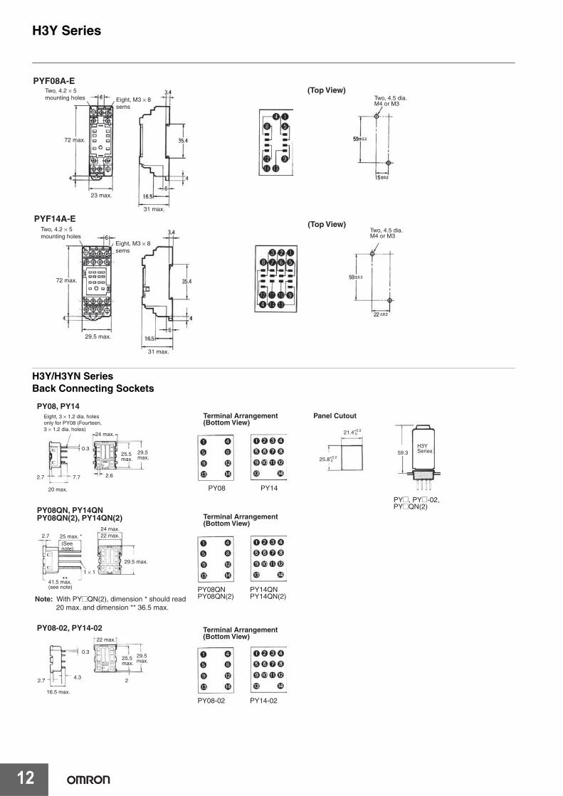
H3Y/H3YN SeriesBack Connecting Sockets
PYF08A-E
31 max.
72 max.
23 max.
(Top View)
PYF14A-E
31 max.
29.5 max.
(Top View)
Two, 4.5 dia. M4 or M3
Two, 4.5 dia. M4 or M3
Two, 4.2 × 5 mounting holes Eight, M3 × 8
sems
Two, 4.2 × 5 mounting holes
Eight, M3 × 8 sems
72 max.
Panel CutoutPY08, PY14
Terminal Arrangement(Bottom View)
PY08QN, PY14QNPY08QN(2), PY14QN(2)
PY08-02, PY14-02
29.5 max.
25.5 max.
24 max.
0.3
2.7 7.7
20 max.
2.6
29.5 max.25.5
max.
22 max.
0.3
2.74.3
16.5 max.
2
(See note)
2.7
29.5 max.
41.5 max.(see note)
25 max. *24 max.22 max.
**1 × 1
H3Y Series
PY@, PY@-02,PY@QN(2)
59.3
21.4+0.2 0
25.8+0.2 0
PY08-02 PY14-02
Terminal Arrangement(Bottom View)
Terminal Arrangement(Bottom View)
PY08QNPY08QN(2)
PY14QNPY14QN(2)
PY08 PY14
Eight, 3 × 1.2 dia. holes only for PY08 (Fourteen, 3 × 1.2 dia. holes)
Note: With PY@QN(2), dimension * should read 20 max. and dimension ** 36.5 max.

H3Y Series
13
Mounting TrackPFP-100N/PFP-50N (see note 1)
End PlatePFP-M
1000 (500) (See note 2)
Note: 1. Meets DIN EN500222. This dimension applies to PFP-50N.
SpacerPFP-S

H3Y Series
14
Safety PrecautionsBe sure to read precautions for all models in the website at the following URL: http://www.omron247.com/.
Warning Indications
Meaning of Product Safety Symbols
Risk of fire and explosion due to arcing and relay heat generation that accompanies switching. Do not use in an environment where flammable or explosive gas is present.
The service life of the output relay varies widely depending on switching capacity and switching conditions. Use only within the rated load and electrical life count, based on actual conditions of use. Risk of contact sticking and burning if used past the service life. Always use a load current that does not exceed the rating, and if a heater is used, use a thermal switch in the load circuit.
Do not remove the outer casing.
In rare circumstances there is a risk of slight electrical shock, fire, or device damage. Do not disassemble, modify, repair, or otherwise touch the inside.
Tighten the screws for the lead wires to the Socket to the following torque.PYF Socket: 0.78 to 1.18 N·mThis is the recommended range when crimp terminals are used.If the screws are not tightened sufficiently on Front-connecting Sockets, the lead wires may come off, connection failure may cause abnormal heating, or fires may occur.If they are tightened excessively, the screw threads may be damaged.
Confirm that the setting dial, indicators and plastic parts are operating normally. Depending on the operating environment, the setting dial, indicators and plastic parts may deteriorate faster than expected, causing the indicators to fail. Periodically perform inspections and replacements.We recommend that you use a surge absorber if surge voltages may occur.When you dispose of the Timer, do so according to all local ordinances for processing industrial waste.
• When selecting a control output, use the H3Y-2/H3YN-2/H3Y-2-B/H3YN-2-B for switching ON and OFF the power and the H3Y-4/H3YN-4/H3Y-4-B/H3YN-4-B for switching ON and OFF the minute load. Gold-plated relays are used in the H3Y-4, H3YN-4, H3Y-4-B, H3YN-4-B, H3YN-4-Z, H3YN-41-Z, H3YN-4-Z-B, and H3YN-41-Z-B Series.
• Connect the power supply between terminals A1 (13) and A2 (14). For a DC power supply, connect the negative side to A1 (13) andthe positive side to A2 (14).
• The operating voltage will increase when using the H3Y/H3YN/H3Y-B/H3YN-B in any place where the ambient temperature ismore than 50°C. Supply 90% to 110% of the rated voltages (at12 VDC: 95% to 110%) when operating at 45°C or higher.
• Do not leave the H3Y/H3YN/H3Y-B/H3YN-B in time-up conditionfor a long period of time (for example, more than one month in any place where the ambient temperature is high), otherwise theinternal parts (aluminum electrolytic capacitor) may becomedamaged. Therefore, the use of the H3Y/H3YN/H3Y-B/H3YN-Bwith a relay as shown in the following circuit diagram isrecommended to extend the service life of the H3Y/H3YN/H3Y-B/H3YN-B.
• The H3YN/H3YN-B must be disconnected from the Socket whensetting the DIP switch, otherwise the user may touch a terminalimposed with a high voltage and get an electric shock.
• Do not connect the H3Y/H3YN/H3Y-B/H3YN-B as shown in thefollowing circuit diagram on the right hand side, otherwise theH3Y's/H3YN's/H3Y-B's/H3YN-B's internal contacts different fromeach other in polarity may become short-circuited.
• Use the following safety circuit when building a self-holding or self-resetting circuit with the H3Y/H3YN/H3Y-B/H3YN-B and anauxiliary relay, such as an MY Relay, in combination.
CAUTIONIndicates a potentially hazardous situation which, if not avoided, may result in minor or moderate injury or in property damage.
Precautions for Safe Use
Supplementary comments on what to do or avoid doing, to use the product safely.
Precautions for Correct Use
Supplementary comments on what to do or avoid doing, to prevent failure to operate, malfunction or undesirable effect on product performance.
Used for general prohibitions for which there is no specific symbol.
Use to indicate prohibitions when there is a risk of minor injury from electrical shock or other source if the product is disassembled.
Used for general mandatory action precautions for which there is no specified symbol.
CAUTION
Precautions for Safe Use
Precautions for Correct Use
Auxiliary relay such as MY Relay
L2L1
L2
L1
Correct Incorrect
: H3Y
Auxiliary relay: MY Relay
H3Y Series
15
• In the case of the above circuit, the H3YN will be in pulse operation. Therefore, if the circuit shown on page 13 is used, no auxiliaryrelay will be required.
• Do not set to the minimum setting in the flicker modes, otherwisethe contact may become damaged.
• Be careful not to apply any voltage to the terminal screws on theback of the Timer. Mount the product so that the screws will notcome in contact with the panel or metal parts.
• Do not use the H3Y/H3YN/H3Y-B/H3YN-B in places where thereis excessive dust, corrosive gas, or direct sunlight.
• Do not mount more than one H3Y/H3YN/H3Y-B/H3YN-B closelytogether, otherwise the internal parts may become damaged.Make sure that there is a space of 5 mm or more between any H3Y/H3YN/H3Y-B/H3YN-B Models next to each other to allow heatradiation.
• The internal parts may become damaged if a supply voltage otherthan the rated ones is imposed on the H3Y/H3YN/H3Y-B/H3YN-B. When more than 100 V is applied to 12 or 24 VDC models, theinternal element (varistor) may break.
• In order to conform to UL and CSA requirements when using theH3Y-4/-4-0/-4-B, H3YN-4/-41/-4-B/-41-B, or H3YN-4-Z/-41-Z/-4-Z-B/-41-ZB, connect the Unit so that output contacts (contactsof different poles) have the same electric potential.
• In cases such as PLC input where the load is extremely small forthe control output of a timer containing a power relay (using otherthan gold-plated contacts), reliability can be increased by usingcontacts of the same poles (e.g., the H3Y-2) in parallel.
• Always use the same type of wire.• Installation
There are no restrictions on the installation orientation. Install theTimer securely.
Precautions for EN 61812-1 ConformanceThe H3Y/H3YN/H3Y-B/H3YN-B as a built-in timer conforms to EN 61812-1 provided that the following conditions are satisfied.
Handling• Do not touch the DIP switch while power is supplied to the H3YN/
H3YN-B.• Before dismounting the H3YN/H3YN-B from the Socket, make
sure that no voltage is imposed on any terminal of the H3YN/H3YN-B.
• The applicable Socket is the PYFA (H3Y/H3YN).• Only basic insulation is ensured between the Y92H-3 Hold-down
Clips and H3Y/H3YN/H3Y-B/H3YN-B internal circuits.• Do not allow the Y92H-3 Hold-down Clips to contact other parts.• The insulation test voltage between different pole contacts for the
4-pole model is the impulse voltage of 2.95 kV.
Wiring• The power supply for the H3Y/H3YN/H3Y-B/H3YN-B must be
protected with equipment such as a breaker approved by VDE.• Basic insulation is ensured between the H3Y's/H3YN's/H3Y-B's/
H3YN-B's operating circuit and control output.• Insulation requirement:
Overvoltage category II,pollution degree 1 (H3Y-4/-4-0/-4-B, H3YN-4/41/-4-B/-41-B,
H3YN-4-Z/-41-Z/-4-Z-B/-41-Z-B), pollution degree 2 (H3Y-2/-2-0/-2-B, H3YN-2/21/-2-B/-21-B)(with a clearance of 1.5 mm and a creepage distance of 2.5 mm at 240 VAC)
• Output terminals next to each other on the H3Y-4 or H3Y-4-0 must have the same polarity.
Recommended Replacement Periods and Periodic Replacement as Preventive MaintenanceThe recommended replacement period for preventive maintenance is greatly influenced by the application environment of the product. As a guideline for models that do not have a Maintenance Forecast Monitor, the recommended replacement period is 7 to 10 years.* To prevent failures that can be caused by using a product beyond its service live, we recommend that you replace the product as early as possible within the recommended replacement period. However, realize that the recommended replacement period is for reference only and does not guarantee the life of the product.Many electronic components are used in the product and the product depends on the correct operation of these components to achieve product functions and performance. However, the influence of the ambient temperature on aluminum electrolytic capacitors is large, and the service life is reduced by half for each 10°C rise in temperature (Arrhenius law). When the capacity reduction life of the electrolytic capacitor is reached, the product may fail. We therefore recommend that you replace the product periodically to minimize product failures in advance.* The following conditions apply: rated input voltage, load rate of 50%
max., ambient temperature of 35°C max., and the standalonemounting method.This product model is designed with a service life of 10 yearsminimum under the above conditions.

MEMO
16

Terms and Conditions of Sale1. Offer; Acceptance. These terms and conditions (these "Terms") are deemed
part of all quotes, agreements, purchase orders, acknowledgments, price lists,catalogs, manuals, brochures and other documents, whether electronic or inwriting, relating to the sale of products or services (collectively, the "Products")by Omron Electronics LLC and its subsidiary companies (“Omron”). Omronobjects to any terms or conditions proposed in Buyer’s purchase order or otherdocuments which are inconsistent with, or in addition to, these Terms.
2. Prices; Payment Terms. All prices stated are current, subject to change with-out notice by Omron. Omron reserves the right to increase or decrease priceson any unshipped portions of outstanding orders. Payments for Products aredue net 30 days unless otherwise stated in the invoice.
3. Discounts. Cash discounts, if any, will apply only on the net amount of invoicessent to Buyer after deducting transportation charges, taxes and duties, and willbe allowed only if (i) the invoice is paid according to Omron’s payment termsand (ii) Buyer has no past due amounts.
4. Interest. Omron, at its option, may charge Buyer 1-1/2% interest per month orthe maximum legal rate, whichever is less, on any balance not paid within thestated terms.
5. Orders. Omron will accept no order less than $200 net billing.6. Governmental Approvals. Buyer shall be responsible for, and shall bear all
costs involved in, obtaining any government approvals required for the impor-tation or sale of the Products.
7. Taxes. All taxes, duties and other governmental charges (other than generalreal property and income taxes), including any interest or penalties thereon,imposed directly or indirectly on Omron or required to be collected directly orindirectly by Omron for the manufacture, production, sale, delivery, importa-tion, consumption or use of the Products sold hereunder (including customsduties and sales, excise, use, turnover and license taxes) shall be charged toand remitted by Buyer to Omron.
8. Financial. If the financial position of Buyer at any time becomes unsatisfactoryto Omron, Omron reserves the right to stop shipments or require satisfactorysecurity or payment in advance. If Buyer fails to make payment or otherwisecomply with these Terms or any related agreement, Omron may (without liabil-ity and in addition to other remedies) cancel any unshipped portion of Prod-ucts sold hereunder and stop any Products in transit until Buyer pays allamounts, including amounts payable hereunder, whether or not then due,which are owing to it by Buyer. Buyer shall in any event remain liable for allunpaid accounts.
9. Cancellation; Etc. Orders are not subject to rescheduling or cancellationunless Buyer indemnifies Omron against all related costs or expenses.
10. Force Majeure. Omron shall not be liable for any delay or failure in deliveryresulting from causes beyond its control, including earthquakes, fires, floods,strikes or other labor disputes, shortage of labor or materials, accidents tomachinery, acts of sabotage, riots, delay in or lack of transportation or therequirements of any government authority.
11. Shipping; Delivery. Unless otherwise expressly agreed in writing by Omron:a. Shipments shall be by a carrier selected by Omron; Omron will not drop ship
except in “break down” situations.b. Such carrier shall act as the agent of Buyer and delivery to such carrier shall
constitute delivery to Buyer;c. All sales and shipments of Products shall be FOB shipping point (unless oth-
erwise stated in writing by Omron), at which point title and risk of loss shallpass from Omron to Buyer; provided that Omron shall retain a security inter-est in the Products until the full purchase price is paid;
d. Delivery and shipping dates are estimates only; ande. Omron will package Products as it deems proper for protection against nor-
mal handling and extra charges apply to special conditions.12. Claims. Any claim by Buyer against Omron for shortage or damage to the
Products occurring before delivery to the carrier must be presented in writingto Omron within 30 days of receipt of shipment and include the original trans-portation bill signed by the carrier noting that the carrier received the Productsfrom Omron in the condition claimed.
13. Warranties. (a) Exclusive Warranty. Omron’s exclusive warranty is that theProducts will be free from defects in materials and workmanship for a period oftwelve months from the date of sale by Omron (or such other period expressedin writing by Omron). Omron disclaims all other warranties, express or implied.(b) Limitations. OMRON MAKES NO WARRANTY OR REPRESENTATION,EXPRESS OR IMPLIED, ABOUT NON-INFRINGEMENT, MERCHANTABIL-
ITY OR FITNESS FOR A PARTICULAR PURPOSE OF THE PRODUCTS.BUYER ACKNOWLEDGES THAT IT ALONE HAS DETERMINED THAT THEPRODUCTS WILL SUITABLY MEET THE REQUIREMENTS OF THEIRINTENDED USE. Omron further disclaims all warranties and responsibility ofany type for claims or expenses based on infringement by the Products or oth-erwise of any intellectual property right. (c) Buyer Remedy. Omron’s sole obli-gation hereunder shall be, at Omron’s election, to (i) replace (in the formoriginally shipped with Buyer responsible for labor charges for removal orreplacement thereof) the non-complying Product, (ii) repair the non-complyingProduct, or (iii) repay or credit Buyer an amount equal to the purchase price ofthe non-complying Product; provided that in no event shall Omron be responsi-ble for warranty, repair, indemnity or any other claims or expenses regardingthe Products unless Omron’s analysis confirms that the Products were prop-erly handled, stored, installed and maintained and not subject to contamina-tion, abuse, misuse or inappropriate modification. Return of any Products byBuyer must be approved in writing by Omron before shipment. Omron Compa-nies shall not be liable for the suitability or unsuitability or the results from theuse of Products in combination with any electrical or electronic components,circuits, system assemblies or any other materials or substances or environ-ments. Any advice, recommendations or information given orally or in writing,are not to be construed as an amendment or addition to the above warranty.See http://www.omron247.com or contact your Omron representative for pub-lished information.
14. Limitation on Liability; Etc. OMRON COMPANIES SHALL NOT BE LIABLEFOR SPECIAL, INDIRECT, INCIDENTAL, OR CONSEQUENTIAL DAMAGES,LOSS OF PROFITS OR PRODUCTION OR COMMERCIAL LOSS IN ANYWAY CONNECTED WITH THE PRODUCTS, WHETHER SUCH CLAIM ISBASED IN CONTRACT, WARRANTY, NEGLIGENCE OR STRICT LIABILITY.Further, in no event shall liability of Omron Companies exceed the individualprice of the Product on which liability is asserted.
15. Indemnities. Buyer shall indemnify and hold harmless Omron Companies andtheir employees from and against all liabilities, losses, claims, costs andexpenses (including attorney's fees and expenses) related to any claim, inves-tigation, litigation or proceeding (whether or not Omron is a party) which arisesor is alleged to arise from Buyer's acts or omissions under these Terms or inany way with respect to the Products. Without limiting the foregoing, Buyer (atits own expense) shall indemnify and hold harmless Omron and defend or set-tle any action brought against such Companies to the extent based on a claimthat any Product made to Buyer specifications infringed intellectual propertyrights of another party.
16. Property; Confidentiality. Any intellectual property in the Products is the exclu-sive property of Omron Companies and Buyer shall not attempt to duplicate itin any way without the written permission of Omron. Notwithstanding anycharges to Buyer for engineering or tooling, all engineering and tooling shallremain the exclusive property of Omron. All information and materials suppliedby Omron to Buyer relating to the Products are confidential and proprietary,and Buyer shall limit distribution thereof to its trusted employees and strictlyprevent disclosure to any third party.
17. Export Controls. Buyer shall comply with all applicable laws, regulations andlicenses regarding (i) export of products or information; (iii) sale of products to“forbidden” or other proscribed persons; and (ii) disclosure to non-citizens ofregulated technology or information.
18. Miscellaneous. (a) Waiver. No failure or delay by Omron in exercising any rightand no course of dealing between Buyer and Omron shall operate as a waiverof rights by Omron. (b) Assignment. Buyer may not assign its rights hereunderwithout Omron's written consent. (c) Law. These Terms are governed by thelaw of the jurisdiction of the home office of the Omron company from whichBuyer is purchasing the Products (without regard to conflict of law princi-ples). (d) Amendment. These Terms constitute the entire agreement betweenBuyer and Omron relating to the Products, and no provision may be changedor waived unless in writing signed by the parties. (e) Severability. If any provi-sion hereof is rendered ineffective or invalid, such provision shall not invalidateany other provision. (f) Setoff. Buyer shall have no right to set off any amountsagainst the amount owing in respect of this invoice. (g) Definitions. As usedherein, “including” means “including without limitation”; and “Omron Compa-nies” (or similar words) mean Omron Corporation and any direct or indirectsubsidiary or affiliate thereof.
Certain Precautions on Specifications and Use1. Suitability of Use. Omron Companies shall not be responsible for conformity
with any standards, codes or regulations which apply to the combination of theProduct in the Buyer’s application or use of the Product. At Buyer’s request,Omron will provide applicable third party certification documents identifyingratings and limitations of use which apply to the Product. This information byitself is not sufficient for a complete determination of the suitability of the Prod-uct in combination with the end product, machine, system, or other applicationor use. Buyer shall be solely responsible for determining appropriateness ofthe particular Product with respect to Buyer’s application, product or system.Buyer shall take application responsibility in all cases but the following is anon-exhaustive list of applications for which particular attention must be given:(i) Outdoor use, uses involving potential chemical contamination or electricalinterference, or conditions or uses not described in this document.(ii) Use in consumer products or any use in significant quantities.(iii) Energy control systems, combustion systems, railroad systems, aviationsystems, medical equipment, amusement machines, vehicles, safety equip-ment, and installations subject to separate industry or government regulations. (iv) Systems, machines and equipment that could present a risk to life or prop-erty. Please know and observe all prohibitions of use applicable to this Prod-uct. NEVER USE THE PRODUCT FOR AN APPLICATION INVOLVING SERIOUSRISK TO LIFE OR PROPERTY OR IN LARGE QUANTITIES WITHOUTENSURING THAT THE SYSTEM AS A WHOLE HAS BEEN DESIGNED TO
ADDRESS THE RISKS, AND THAT THE OMRON’S PRODUCT IS PROP-ERLY RATED AND INSTALLED FOR THE INTENDED USE WITHIN THEOVERALL EQUIPMENT OR SYSTEM.
2. Programmable Products. Omron Companies shall not be responsible for theuser’s programming of a programmable Product, or any consequence thereof.
3. Performance Data. Data presented in Omron Company websites, catalogsand other materials is provided as a guide for the user in determining suitabil-ity and does not constitute a warranty. It may represent the result of Omron’stest conditions, and the user must correlate it to actual application require-ments. Actual performance is subject to the Omron’s Warranty and Limitationsof Liability.
4. Change in Specifications. Product specifications and accessories may bechanged at any time based on improvements and other reasons. It is our prac-tice to change part numbers when published ratings or features are changed,or when significant construction changes are made. However, some specifica-tions of the Product may be changed without any notice. When in doubt, spe-cial part numbers may be assigned to fix or establish key specifications foryour application. Please consult with your Omron’s representative at any timeto confirm actual specifications of purchased Product.
5. Errors and Omissions. Information presented by Omron Companies has beenchecked and is believed to be accurate; however, no responsibility is assumedfor clerical, typographical or proofreading errors or omissions.

OMRON CANADA, INC. • HEAD OFFICEToronto, ON, Canada • 416.286.6465 • 866.986.6766 • www.omron247.com
OMRON ELECTRONICS DE MEXICO • HEAD OFFICEMéxico DF • 52.55.59.01.43.00 • 01-800-226-6766 • [email protected]
OMRON ELECTRONICS DE MEXICO • SALES OFFICEApodaca, N.L. • 52.81.11.56.99.20 • 01-800-226-6766 • [email protected]
OMRON ELETRÔNICA DO BRASIL LTDA • HEAD OFFICESão Paulo, SP, Brasil • 55.11.2101.6300 • www.omron.com.br
OMRON ARGENTINA • SALES OFFICECono Sur • 54.11.4783.5300
OMRON CHILE • SALES OFFICESantiago • 56.9.9917.3920
OTHER OMRON LATIN AMERICA SALES54.11.4783.5300
Authorized Distributor:
M54I-E-02 09/16 Note: Specifications are subject to change. © 2016 Omron. All Rights Reserved. Printed in U.S.A.
Printed on recycled paper.
OMRON AUTOMATION AMERICAS HEADQUARTERS • Chicago, IL USA • 847.843.7900 • 800.556.6766 • www.omron247.com
OMRON EUROPE B.V. • Wegalaan 67-69, NL-2132 JD, Hoofddorp, The Netherlands. • +31 (0) 23 568 13 00 • www.industrial.omron.eu
Controllers & I/O • Machine Automation Controllers (MAC) • Motion Controllers • Programmable Logic Controllers (PLC) • Temperature Controllers • Remote I/O
Robotics • Industrial Robots • Mobile Robots
Operator Interfaces• Human Machine Interface (HMI)
Motion & Drives• Machine Automation Controllers (MAC) • Motion Controllers • Servo Systems • Frequency Inverters
Vision, Measurement & Identification• Vision Sensors & Systems • Measurement Sensors • Auto Identification Systems
Sensing• Photoelectric Sensors • Fiber-Optic Sensors • Proximity Sensors • Rotary Encoders • Ultrasonic Sensors
Safety • Safety Light Curtains • Safety Laser Scanners • Programmable Safety Systems • Safety Mats and Edges • Safety Door Switches • Emergency Stop Devices • Safety Switches & Operator Controls • Safety Monitoring/Force-guided Relays
Control Components • Power Supplies • Timers • Counters • Programmable Relays • Digital Panel Meters • Monitoring Products
Switches & Relays • Limit Switches • Pushbutton Switches • Electromechanical Relays • Solid State Relays
Software • Programming & Configuration • Runtime