Embed Size (px)
Citation preview

2-10 Specifications are subject to change without notice (30.11.2001)
Control inputIn most SSRs galvanic separation isachieved by optocouplers. These opto-couplers, equipped with integrated triggercircuit (optotriac), provide the switchingfunction required for the correspondingload type.
We distinguish between:
- ZS: Zero Switching- IO: Instant-on Switching- PS: Peak Switching- AS: Analog Switching- DCS: DC Switching- FS: Full Cycle Switching
Types of SSRs
When applying the control voltage, the AC SSR output is activatedat the first zero crossing of the line voltage. The response time ishereafter less than a halfperiod, i.e. typically below 10 ms at 50 Hz.
ZS SSRs are employed in a host of applications with resistive loads(temperature control) and control of incandescent lamps. The ZStypes are the most commonly used SSRs due to their extensive usewith plastic moulding machines, packing machines, soldering ma-chines as well as machines for the food processing industry.
ZS SSRs are used in various applications, such as interfacing resis-tive loads or lighting installations. Due to high surge current- andblocking voltage capabilities, SSRs of this switching type will alsoperform successfully with most inductive and capacitive loads.
Zero Switching SSR (ZS)For resistive, inductive or capacitive loads
Controlinput
Fuse
Varistor
Load
Func
tio
nA
pp
licat
ion
Des
crip
tio
nSolid State RelaysGeneral Information
Instant-on Switching SSR (IO)For inductive loads
The SSR output is activated immediately after applying control voltage.Consequently, this relay can turn on anywhere along the AC sinusoidalvoltage curve. The typical response time is thus less than 1 ms.(Relays equipped with reed contacts are inherently instant-on types.)
This SSR is particularly suitable in applications where a fast responsetime or phase angle control is desired.
Controlinput
Fuse
Varistor
Inductive load
Line voltage (VAC)
Controlinput
Load curent(AAC)
Line voltage (VAC)
Controlinput
Load current(AAC)
t
t
t
t
t
t
Typ
e
Note: For SSR without integrated voltage protection
Gross Automation (877) 268-3700 · www.carlogavazzisales.com · [email protected]

Specifications are subject to change without notice (30.11.2001) 2-11
DC Switching SSR (DCS)For resistive and inductive loads
The power semiconductor in the DC switching relay operates in ac-cordance with the control input status. The response time is lessthan 100 µs.
DCS SSRs are used with resistive and inductive loads for the controlof DC motors and valves.
When switching inductive loads it will be necessary to interconnecta free wheeling diode surplus voltage parallel to the load as protec-tion.
Controlinput
Fuse
Load
Line voltage (VAC)
Controlinput
Load Current(AAC)
Line voltage (VAC)
Controlinput
Load Current(AAC)
Solid State RelaysGeneral Information
Types of SSRs (cont.)
Func
tio
nA
pp
licat
ion
Des
crip
tio
nTy
pe Peak Switching SSR (PS)
For inductive loads with remanent iron core
The peak switching SSR is designed in a way that the power outputis activated at the first peak of the line voltage upon application ofthe control voltage. After the first half period the PS SSR operates asan ordinary ZS relay. The peak of the inrush current could hereafterbe reduced during the first half-period for inductive loads.
Controlinput
Fuse
Varistor
Inductive load
t
t
t
t
t
t
Gross Automation (877) 268-3700 · www.carlogavazzisales.com · [email protected]

2-12 Specifications are subject to change without notice (30.11.2001)
Types of SSRs (cont.)
Solid State RelaysGeneral Information
Low Noise SSR (LN)For resistive and inductive loads
System Monitoring SSR (SM)For resistive and inductive loads
The Low Noise SSR is designed for light industrial environments andfulfills the generic emission standard EN50081-1. By controlling theswitching mode of the semiconductors, the peak level of the zerovoltage turn-on is minimised, thus reducing the noise emitted by theSSR.
Low Noise SSRs are particularly suitable for applications where ele-ctromagnetic noise must be limited to avoid interference with otherequipment. In this kind of environment, noise generated by standardSSRs is considered critical or unsafe. Low noise SSRs can be usedwith both resistive and inductive loads.
The system monitoring (sense) SSR provides an alarm output in theevent of a circuit failure. Internal circuits monitor:- line voltage- load current- correction functioning of the SSR- SSR input status.
The relay is designed for applications where immediate fault detecti-on is required. An alarm output signal is available to determine fault status.
Func
tio
nA
pp
licat
ion
Des
crip
tio
nTy
pe
Holding Current Level
Zero Voltage
Noise Decreased Drastically
Holding Current Level
Zero Voltage
Peak that Generates Noise
NormalRelay OFF
OperationRelayON
LineVoltageLoss
LineVoltageLoss
LoadOpenCircuit
DCSupplyLoss
DCSupplyLoss
RelayRemainsOFF
ShortedRelay
ShortedRelay
Line Voltage
Load Current
Control
Green LED
DCSupply
Red LED
Alarm Output (normally open type)
=Half LED light intensity
~S4 1
3 2SSR
ControlInput
N/L2
L1
Note: Connection “S” does not apply to SSRs with integrated heatsink
3+4-
5 Not Con.6 Control (High/Low)7 Alarm (PNP/NPN)
Fuse
Load
L2/N
L1
1
2
OnAlarm
Load CurrentPhaseVoltage across SSR
Normal Zero Switching Low Noise Zero Switching
Gross Automation (877) 268-3700 · www.carlogavazzisales.com · [email protected]

Specifications are subject to change without notice (30.11.2001) 2-13
Solid State RelaysGeneral Information
Types of SSRs (cont.)
Power outputDepending on the application, variousquestions concerning the power outputof the SSR need to be clarified. The mostimportant parameters are
- Line voltage (load voltage) - Load current - Type of load (application)
in order to be able to select the correctSSR. To avoid unnecessary maintenanceexpenses, the selection needs to be asaccurate as possible.
Line voltageThe voltage range of an SSR must be se-lected according to the line voltage in theapplication. For the non-repetitive peaktransient voltage of the SSR, both tran-sients from the mains and voltage peaksfrom the application need to be consid-ered.
A corresponding protective element likea freewheeling diode (only DC), a varistoror a snubber (RC) can be incorporated inorder to protect the output semiconduc-tor.
Load currentThe relay must be selected in a way thatthe continuous load current in the appli-cation does not exceed the correspond-ing nominal value of the relay. It is impor-tant to take into consideration the con-tinuous load current in relation to the am-bient temperature. With inductive loads,such as motors, valves, etc., the SSRmust be sized or selected according tothe highest expected surge current.
Since the control input of the analog relay - according to speci-fications 4 to 20 mADC - can be varied, the output operates inaccordance with the phase control principle. The relay isequipped with a built-in synchronization circuit in order toachieve phase angle control. The output is proportional to theinput voltage or input current. The transfer function is linearizedand reproducible.
These SSRs are highly advantageous in closed loop applicationsor where soft starting can limit high inrush currents.
The Full Cycle SSR uses an analogue switching principle thatprovides a number of full cycles that are evenly distributedover a fixed time period. The number of cycles switched dur-ing the time period is directly proportional to the control inputapplied to the SSR.
Since the full cycles are distributed, this SSR provides high ac-curacy in temperature control and creates less noise.Compared to conventional Burst control, the Full Cycle SSRreduces the stress on the load by limiting the band withinwhich the load cycles.
Analog Switching SSR (AS)For resistive, inductive or capacitive loads
Controlcircuit Inductor Fuse
Varistor Capacitor
Load
Temp. sensor
Line voltage(VAC)
Controlinput
Load cur-rent (AAC)
t
t
t
Full Cycle SSR (FC)For resistive loads
Func
tio
nA
pp
licat
ion
Des
crip
tio
nTy
pe
Burst Full Cycle Switching
Analogue Full Cycle Switching
Period
T
T
Supply(V type only)
T1
A3
A4
T2
L1
A1
A2
L2
L1 L3L2
SSR+
-AnalogueControlInputI/V type
Gross Automation (877) 268-3700 · www.carlogavazzisales.com · [email protected]

2-14 Specifications are subject to change without notice (30.11.2001)
Types of SSRs (cont.)
Snubberless TriacThe snubberless triac is a further development ofthe triac in which the two thyristors on the chip arewell separated. Consequently, a higher dV/dt capa-bility is achieved.
In this way the internal snubber can be eliminated.
AlternistorThe alternistor is developed especially for industri-al use. The alternistor consists of two antiparallelthyristors and a gate triac integrated in the samechip. The thyristors are well separated. The triacwill block uncontrolled turn-on during commuta-tion.
TriacThe triac consists of two antiparallel thyristorsmounted on the same chip in order to give full-wave operation at a single gate.
A snubber is often mounted across the SSR inorder to reduce the dV/dt.
Thyristor (SCR)The antiparallel thyristor solution is most commonfor industrial SSRs. The solution requires two sep-arate SCRs and two trigger circuits, which giveoptimum dV/dt capability.
TransistorThe transistor option - often the open collectorconfiguration - is used in the DC SSRs. A free-wheeling diode is normally mounted across thetransistor to avoid damage from back-EMV frominductive loads.
The triac SSR is the most cost-effective solution inapplications with low dV/dt demands, e.g. applica-tions with heating elements with almost constantresistance.
The snubberless triac is one of the latest improve-ments from semiconductor manufacturers.
The elimination of the snubbers also reduces theleakage current in the switching circuit.
The snubberless triac is common in resistive andinductive applications (up to 25 A) .
The alternistor output is widely used in SSRs for re-sistive and inductive loads.
The antiparallel SCR SSR is used for all load types,such as resistive, inductive and even capacitiveloads.
An SCR in a diode bridge is only used in PCB relayswith load currents of less than 2 A.
The transistor is used for DC loads such as DCmotors, solenoids or valves.
Load switching component Symbol Application
Solid State RelaysGeneral Information
Advantages and LimitationsSSRs offer the user many outstandingfeatures and should be treated as a sepa-rate class of relay. However, due to the de-sign of SSRs, the user is always facedwith a few limitations which are differentfrom those of electromechanical relays(EMR). The following outline of advan-tages and limitations of SSRs will serve asa guide to the professional use of thesedevices.
Advantages* Long life and high reliability - more than
109 operations* No contact arcing, low EMI, high surge
capability* High resistance to shock and vibration* High resistance to aggressive chemicals
and dust* No electromechanical noise* Logic compatibility* Fast switching* Low coupling capacitance
Long life and high reliabilityIn SSRs from Carlo Gavazzi an optimizedthermal design is achieved by applyingthe "Direct Copper Bonding" technology.This technology finally eliminates thethermal fatigue between chip (silicon) andterminals (copper). Furthermore, it re-duces the thermal resistance betweenjunction and ambient.
The DCB substrate, on which the chip issoldered, consists of a ceramic insulator(Al2O3) with a layer of copper (Cu) on bothsides. The copper is bonded with the ce-ramic material in order to get similar ther-mal expansion conditions for both mate-rials. Thereby the mechanical stress be-tween silicon chip and copper will be min-imized while the relay is in operation.
The ceramic material provides a 4 kV in-sulation between copper leads andheatsink. A lower temperature difference(∆T) on the junction will increase the life-time of the relay, and an increase of the
switching frequency can help to achievea more reliable application.
No contact arcingNo contact arcing will occur since switch-ing takes place inside the semiconductormaterial, which changes from a non-con-ductor to a conductor at the signal of thecontrol input. Line and load radiation arereduced considerably because the SCRs,alternistors or triacs are basically currentlatching devices, which will turn off assoon as the current is near zero. This isknown as "zero crossing turn off". Thisgreatly reduces the radiated electromag-netic interference (EMI), and this reduc-tion of EMI is often well received by theequipment designers.
High resistance SSRs with optocoupler inputs are fullyembedded in the housing material andconsequently, since no moving parts areused, they are highly resistant to vibra-tions and shock.
Gross Automation (877) 268-3700 · www.carlogavazzisales.com · [email protected]

Specifications are subject to change without notice (30.11.2001) 2-15
Advantages and Limitations (cont.)
Switching characteristics of EMR and SSR
Control inputControl input
Load voltage Load voltage
Control voltage
SSREMR
Reactiontime
Bouncetime
Reaction time < 1 ms (IO)< 10 ms (ZS)
Solid State RelaysGeneral Information
High resistance to aggressivechemicals and dustNeither sand, dust nor aggressive che-micals can disrupt the trouble-free ope-ration of a Solid State Relay.
No electromechanical noiseSSRs do not create mechanical noisesince everything is controlled entirelyelectronically. In applications such as of-fice machinery or in medical equipmentthis is for the benefit of the user.
Logic compatibilitySSRs are available with input circuitswhich are directly compatible with logiccomponents for CMOS, TTL, micropro-cessors or analog circuits.Logic compati-bility is important since SSRs are often di-rectly controlled by PLCs or other logicoutputs. High-current SSRs can be drivenwith minimal currents of less than 10 mA@ 24 VDC.
The direct copper bonding technology
Al2O3
Si
Solder
Cu
Al
Logic compatibility to PC/PLC
Fast switchingInstant-on SSRs feature a turn-on time ofless than 1 ms. This fast switching capa-bility makes it possible to phase anglecontrol the power output by means of anexternal control circuit. In the analogswitching relay this function is alreadybuilt-in.
Low coupling capacitanceThe very low coupling capacitance be-tween input and output of SSRs is inher-ent in the optocoupler used in most SSRdesigns. The resulting lower off-stateleakage current is important in medicalapplications, office machinery, householdappliances or in industrial applications.
Limitations* Contact voltage drop* Finite transient voltage resistance and
dV/dt limitations* Leakage currents and dI/dt limitations
Contact voltage dropThe contact voltage drop across thethyristor is usually 1 to 1.6 V. Voltage drop
application. The energy absorption of adisc varistor is always proportional to itssize. Therefore it is recommended to usevaristors with a diameter of minimum 14mm for PCB SSRs and 20 mm relays forchassis mounting.
Limitations due to rapid voltagechangeThe junction of any semiconductor ex-hibits some capacitance. An alternatingvoltage imposes capacitance on thisjunction, which results in a current where I = C x dV/dt.
If this current is sufficiently high, a regen-erative action may occur causing theSCR to turn on. This regenerative actionis similar to the gate turn-on.
The expression "dV/dt" defines a voltagechange in relation to time. It is usually giv-en in volts per microsecond (V/µs).
together with load current are basic fig-ures for the calculation of the power loss-es. Excessive heat can easily destroy thepower semiconductor. It is therefore indis-pensable to calculate the power dissipa-tion and to use adequate heatsinking.
Finite transient voltage resistanceThe AC mains contains all kinds of volt-age spikes and transients. These tran-sients may result from other componentslike motors, solenoids, switches, trans-formers or contactors - not to mention ex-ternal sources such as lightning.
If overvoltage protection is not provided,the thyristors used in SSRs might exceedtheir breakdown voltage and will turn onfor less than a halfperiod. The non-repetitive peak voltage is the maximumoff-state voltage which the output switch-ing device can withstand without switch-ing on.
Whenever they are not built-in, varistorsfor transient voltage protection should befitted across the output. The varistorsmust be rated for the line voltage in the
Gross Automation (877) 268-3700 · www.carlogavazzisales.com · [email protected]

2-16 Specifications are subject to change without notice (30.11.2001)
Advantages and Limitations (cont.)
Heat dissipation from contact voltage drop
Heat
ChipCurrent ↑∆V
Solid State RelaysGeneral Information
Off-state dV/dtThe off-state dV/dt is the parameter defin-ing the voltage rise capability of the SSR,i.e. the max. allowable rate of increase involtage across the output terminals whichwill not switch on the SSR. Typically it lieswithin the range of 100 to 1000 V/µs.
Commutating dV/dtThe dV/dt is expressed in volts per mi-crosecond (V/µs) and indicates the rate ofvoltage rise which the SSR output switch-ing device can withstand without beingturned on again as long as the load is off.The commutating dV/dt rating of an SSRis a measure of its ability to switch off aninductive load.
With the current crossing zero and turn-ing off the load, the voltage rise across theoutput semiconductor could, due to toohigh dV/dt, immediately turn on the SSR(without applying control voltage).Consequently, with inductive loads,where the phase shift between currentand voltage is large, the chance of anexceptional dV/dt value is very high.
SnubberWith a high load inductance, a very com-mon method to eliminate random firingthrough interference, or spontaneous re-firing through commutating dV/dt, is toconnect an RC network, known as "snub-ber", across the SSR terminals. The ca-pacitance (C) in conjunction with the im-pedance of the load attenuates the volt-age waveforms transmitted via the mainsor occuring when switching on an induc-tive load.
used, or the circuit may actually betouched, say for servicing. A resistoracross the indicator and a line safetybreaker are the standard means by whichthese limitations can be overcome.
dI/dt limitationThe rate of rise of current (dI/dt) is nor-mally assumed to be low compared withthe time required for the thyristor to reachfull on-state conduction. In installationsthere is a certain amount of inductancewhich limits the rate of rise of current. Inthe SSR data sheet the dI/dt is given. ThedI/dt usually lies within the range of 10 to100 A/µs. The necessary inductance canbe calculated as follows:
The inductance of the load, the supplyand all power cables in between need tobe considered as well.
Standard values are:R < 100 Ω, C < 0.22 µF.
Most of the modern SSRs from CarloGavazzi have such a high dV/dt capabil-ity that the snubber can be eliminated.
Off-state leakage currentSSRs always have off-state leakage cur-rents. The thyristors, control circuitry andsnubber network all supply small off-statecurrents, which usually total from about 1to 10 mA rms.
These leakage currents should be takeninto account when either indicators are
RemediesIn order to achieve proper function and areliable application the user should con-sider:
1. A heatsink to remove the dissipated power
2. A varistor to protect against overvolt- age transients
3. A fuse to limit current passing through the SSR thus resulting in:
a. short-circuit protectionb. overload protection
4. Self-induction in the system must be sufficiently high, in order to limit dI/dt.
5. A circuit breaker to disconnect me-chanically the SSR application from the mains (safety measure).
Snubber circuit
Loadcurrent
Controlinput
SSR∆ voltage
t
t
t
dV/dt
Up [V]
The dV/dt caused by phase shift
Rate of rise of voltage - the dV/dt
∆V
time [µs]
dV/dt ≈ ∆t∆V
0.63 x Up
τ≈
Up [V]
∆ t ≈ τ
Gross Automation (877) 268-3700 · www.carlogavazzisales.com · [email protected]

Specifications are subject to change without notice (30.11.2001) 2-17
Solid State RelaysGeneral Information
Ultrafast Fuse
Varistor (20mm)
Ultrafast Fuse
Varistor (20mm)
Ultrafast Fuse
Varistor (20mm)
Ultrafast Fuse
Varistor (20mm)
1. General Information
Load current, line voltage, am-bient temperature and loadtype are crucial factors whenusing Solid State Relays. It isnecessary to carry out a criticalanalysis of the application andperform proper calculationswhen using all Carlo GavazziSolid State Relay products.
2. Overload Protection
The relay must be protectedagainst overload (short-cir-cuit) by means of an externalsemiconductor fuse. CarloGavazzi provides the basiccalculation to help you selectthe right fuse.
3. Voltage Transient Protection
Ideal protection is achievedthrough varistors (metal oxidevaristors) mounted across thepower semiconductor. Thevaristor voltage has to matchwith the line voltage in yourapplication. Wrong selectioncan cause limited protectionor a hazardous situation. Ona number of models, thevaristor is already mountedinternally.
4. Overheat Protection
The relay must be protectedeffectively against excessiveheat. Thermal stress will re-duce the lifetime of your SSRdrastically. Therefore it isnecessary to choose the ap-propriate heatsinks, takinginto account ambient tem-perature, load current andduty cycle. A thin film of ther-mally conducting compoundwill reduce the thermal resis-tance between the relay andthe heatsink.
Important matters to be observed when installing an SSR:
When installed properly, the Solid State Relay will last millions of operations
Heatsink
Fuse
Varistor
Application
When looking for a relay to solve yourswitching application requirements, youshould consider the advantages of SSRsand how to deal with the limitations.
A. Heating systemsElectric ovensSoldering systemsPlastic processing systemsGalvanic systems (electro-plating)Film developing systemsPackaging industryRubber industryCooking systems
B. Optical equipment and systemsPhotocopiersLight equipmentTraffic light controls
C. Electric motor drivesPosition control X-YValve positioningSoft starting, braking, reversing
D. Transformer supplyWelding equipmentLight systems with transformersupply
Gross Automation (877) 268-3700 · www.carlogavazzisales.com · [email protected]

2-18 Specifications are subject to change without notice (30.11.2001)
Solid State RelaysGeneral Information
Insulation
Insulation
Rated insulation voltageInput to output ≥ 4000 VACrms
Rated insulation voltageOutput to case ≥ 2500 VACrms
Insulation resistanceInput to output ≤ 1010 Ω
Insulation resistanceOutput to case ≤ 1010 Ω
Insulation capacitanceOutput to case ≤ 8 pF
Insulation capacitanceInput to output ≤ 50 Insulation resistance
output to caseDielectrical strength and insulation resistance, capaci-tance from output to case (heatsink).
Insulation resistanceinput to outputDielectrical strength and insulation resistance, capaci-tance between input and output.
Insulation resistance (output to case)
This is the rated insulation and, conse-quently, when the SSR is mounted on anexternal heatsink, the heatsink must beconnected to protective earth (PE).
Insulation resistance (input to output)Depending on the applied input voltage,the input voltage insulation is either rein-forced or rated insulation.
A. When the input voltage is ≤ 25 VACrmsor ≤ 60 VDC, there is reinforced in-sulation between input and output.This means that the input voltage caneither be PELV (protected extra low
voltage, PE connected) or SELV (spe-cial extra low voltage, unprotected).
B. When the input voltage is higher thanthe voltages defined under A and ≤ 50VAC or ≤ 120 VDC, there is reinforcedinsulation between input and output.This means that the input voltage canbe FELV (functional extra low voltage,PE connected).
C. When input voltages are higher thanthose mentioned under A and B, theyare regarded as line voltage inputsand, consequently, there is only ratedinsulation between input and outputin this case.
Protective earth connection (PE)Where protective earth (PE) is connectedto the input, either of the two input termi-nals can be used. In the case of heatsinkmounting versions the heatsink must beconnected to protective earth (PE) due tothe rated insulation. This procedure is inaccordance with IEC 60204-1, EN 60204-1,VDE 0113T1 and other important interna-tional application standards.
Electrical build-upSafety regarding clearance, creepageand insulation barriers is based on the lat-est international coordination standardsIEC 60664, 60664-1.
Gross Automation (877) 268-3700 · www.carlogavazzisales.com · [email protected]

Specifications are subject to change without notice (30.11.2001) 2-19
Housing Specifications Weight Approx. 110 g
Housing material Noryl GFN 1, black
Base plate Aluminium
Potting compound Polyurethane
RelayMounting screws M5Mounting torque ≤ 1.5 Nm
Control terminalMounting screws M3 x 6Mounting torque ≤ 0.5 Nm
Power terminal
General Specifications
StandardsTo ensure the widest possible scope of applica-tion in electrical equipment and machinery, CarloGavazzi's SSRs are designed in accordancewith the following standards:
IEC 60158-2, 60204-1, 60947-1, 60947-4,60529CSA C.22.2.14UL 0508, 0840VDE 0805, 0750, 0700
Housing Specifications
MaterialHousings and potting compound are UL-approved and flame, heat and impact resistant.
Protection against electric shockTerminal protection against direct contact.
Degree of protection (IEC 60529)IP 00 Non-protectedIP 10 Back-of-hand protectedIP 20 Finger-protected
The technical specifications of the degree ofprotection are in accordance with IEC 60529(IEC 60947-1).
General SpecificationsOperational voltage range 24 to 280 VACrms
Non-rep. peak voltage ≥ 650 Vp
Zero voltage turn-on ≤ 20 V
Operational frequency range 45 to 65 Hz
Power factor ≥ 0.5
Approvals CSA, UL, CUL VDE, TUV
MaterialHousings: Noryl GFN 1 Potting compound: Polyurethane.
ApprovalsCSA, UL, CUL VDE, TUV
Solid State RelaysGeneral Information
Canada, Canadian StandardsAssociation(C 22.2 NO 14)
USA, Underwriters Laboratories Inc.(UL 508 & UL 840)
Germany, Verband der Elektronik Informationstechnik e.v.(VDE 0805, 0700, 0750)
LISTED
RUL
LISTED
RUL
C
Germany, Rheinland/Berlin -Brandenburg(VDE 0805, 0700, 0750)
Gross Automation (877) 268-3700 · www.carlogavazzisales.com · [email protected]
2-20 Specifications are subject to change without notice (30.11.2001)
Solid State RelaysGeneral Information
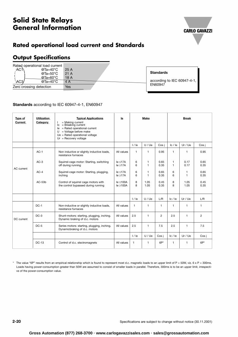
Output SpecificationsRated operational load current
AC1 @Ta=40°C 25 A @Ta=50°C 21 A@Ta=60°C 18 A
AC3 @Ta=40°C 4 AZero crossing detection Yes
Standards
according to IEC 60947-4-1,EN60947
Type of Utilization Typical Applications Ie Make BreakCurrent Category I = Making current
Ic = Breaking currentIe = Rated operational currentU = Voltage before makeUe = Rated operational voltageUr = Recovery voltage
I / Ie U / Ue Cos j Ic / Ie Ur / Ue Cos j
AC-1 Non inductive or slightly inductive loads, All values 1 1 0.95 1 1 0.95resistance furnaces
AC-3 Squirrel-cage motor: Starting, switching Ie ≤17A 6 1 0.65 1 0.17 0.65 off during running Ie ≥17A 6 1 0.35 1 0.17 0.35
AC current AC-4 Squirrel-cage motor: Starting, plugging, Ie ≤17A 6 1 0.65 6 1 0.65
inching Ie ≥17A 6 1 0.35 6 1 0.35
AC-53b Control of squirrel cage motors with Ie ≤100A 8 1.05 0.45 8 1.05 0.45the control bypassed during running Ie ≥100A 8 1.05 0.35 8 1.05 0.35
I / Ie U / Ue L/R Ic / Ie Ur / Ue L/R
DC-1 Non-inductive or slightly inductive loads, All values 1 1 1 1 1 1resistance furnaces
DC-3 Shunt-motors: starting, plugging, inching. All values 2.5 1 2 2.5 1 2DC current Dynamic braking of d.c. motors
DC-5 Series motors: starting, plugging, inching. All values 2.5 1 7.5 2.5 1 7.5 Dynamicbraking of d.c. motors
I / Ie U / Ue Cos j Ic / Ie Ur / Ue Cos j
DC-13 Control of d.c. electromagnets All values 1 1 6P* 1 1 6P*
Standards according to IEC 60947-4-1, EN60947
Rated operational load current and Standards
* The value “6P” results from an empirical relationship which is found to represent most d.c. magnetic loads to an upper limit of P = 50W, viz. 6 x P = 300ms.Loads having power-consumption greater than 50W are assumed to consist of smaller loads in parallel. Therefore, 300ms is to be an upper limit, irrespecti-ve of the power-consumption value.
Gross Automation (877) 268-3700 · www.carlogavazzisales.com · [email protected]

Specifications are subject to change without notice (30.11.2001) 2-21
Norms
Solid State RelaysGeneral Information
Carlo Gavazzi products are designed in accordance to both CE and various third party norms. Typical third party approval bodies are UL, CSA, VDE and TUV. Whereas the CE mark is self regulatory, the other approvals are governed by third party test labs.
CE is divided into 2 separate sections; the EMC directive and the LVD directive. The following is a list ofEMC generic norms which Carlo Gavazzi Solid State Relays are designed in accordance with:
EN 60947-1 Low Voltage switchgear and controlgear. Part 1 – General Rules
EN 60947-4-1 Low Voltage switchgear and controlgear. Part 4 – Contactors and motor starters. Section 1 – Electromechanical contactors and motor starters.
EN 60947-4-2 Low Voltage switchgear and controlgear. Part 4 – Contactors and motor starters. Section 2 – AC semiconductor motor controllers and starters.
IEC 529 Degrees of protection provided by enclosures.
HD 419.2S1(BS5424-2) Low-voltage control gear – Specification for semiconductor contactor.
IEC 664-1 Insulation coordination for equipment within low voltage systems. Part 1 – Priciples, requirements and tests.
IEC 664-3 Insulation coordination for equipment within low voltage systems. Part 3 – Use of coatings to achieve insulation coordination of printed board assemblies.
EN 50081-1 EMC - Generic Emission Standard Part 1 : Residential, Commercial and Light Industry
EN 50081-2 EMC - Generic Emission Standard Part 2 : Industrial Environment
EN 50082-1 EMC Generic Immunity Standard Part 1 : Residential, Commercial and Light Industry
EN 61000-6-2 EMC - Generic Immunity Standard Part 2 : Industrial Environment
EN 61000-4-2 Electrostatic discharge immunity test
EN 61000-4-3 Radiated, radio-frequency, electromagnetic field immunity test
EN 61000-4-4 Electrical fast transient / burst immunity test
EN 61000-4-5 Surge immunity test
EN 61000-4-6 Immunity to conducted disturbances, induced by radio-frequency fields
EN 55011 / 22 Radiated and conducted electro magnetic emission
IEC 68-2-6 Vibration test
These generic emc norms give a list of limits which our products must reach when tested according to the various tests.These tests are done according to the following norms:
Apart from EMC norms, our products are also designed according to the Low Voltage Directive norms. Solid state relays aredesigned in accordance with some of the following:
Apart from the LVD norms, other third party approval bodies also require the device to be constructed in accordance to theirown norms. The UL approval requires the device to be according to UL508 (Industrial control equipment) and UL840(Insulation Coordination including clearance and creepage distances for electrical equipment). The CSA approval requireconformity to C22.2 No 14-95 (Industrial Control Equipment – Industrial Products). VDE and TUV approvals are given in ac-cordance with EN 60950 (VDE 0805) – Safety of information technology equipment, EN60335-1 (VDE 0700) – Safety ofhousehold and similar electrical appliances. Part1- General requirements, EN60601-1 (VDE 0750) – Medical ElectricalEquipment. Part 1- General Requirements for safety.
Gross Automation (877) 268-3700 · www.carlogavazzisales.com · [email protected]

2-22 Specifications are subject to change without notice (30.11.2001)
Solid State RelaysGeneral Information
RAP 40 A . RAOperational voltage range 10 V to 440 VACrms 20 VNon-rep. peak voltage ≥ 1000 VS ≥ 12Zero voltage turn-on ≤ 20 V ≤ 40Operational frequency range 45 to 65 Hz 45 bPower factor ≥ 0.2 ≥ 0.2Approvals CSA, UL, VDE CSA
General Specifications
Operational voltage rangeThe voltage range within which correct operation by the SSR is possible (rms-value).
Non-rep. peak voltageWhen this voltage limit is exceeded, the SSR will switch through without being triggered.
As prescribed by the standard DIN VDE 0160, electricalequipment in power installations must ensure undistur-bed operation for 1.3 ms in case of a transient overvol-tage, which may be up to 2.3 x nominal voltage. Themax. allowable operational voltage is thus dependenton the non-repetitive peak voltage.
t
u
du
dt
AC voltage with transient overvoltage protection
Peak voltage
Input SpecificationsControl voltage range 3.5 V to 40 VDCPick up voltage ≤ 3.5 VDCDrop out voltage ≥ 1 VDCReverse voltage ≤ 0 VDCResponse time pick up ≤ 1/2 cycleResponse time drop out ≤ 1/2 cycleInput current
(through current limiter) ≤ 12 mA
Control voltage
≤ 40 VDC
≤ 3.5 VDC
≥ 1 VDC
Load IN
Load OUT
Undefined area
Transient Voltage Suppression
Gross Automation (877) 268-3700 · www.carlogavazzisales.com · [email protected]

Specifications are subject to change without notice (30.11.2001) 2-23
Thermal protection
Fig. 2
25
22.5
20
17.5
15
12.5
10
7.5
5
2.5
2.70
3.10
3.61
4.26
5.14
6.38
8.25
11.4
17.7
-
20
2.34
2.69
3.13
3.70
4.47
5.56
7.19
9.94
15.4
-
30
1.61
1.86
2.18
2.59
3.14
3.91
5.08
7.04
11.0
-
50
1.25
1.45
1.70
2.03
2.47
3.09
4.02
5.59
8.74
18.2
60
0.89
1.04
1.23
1.47
1.80
2.27
2.97
4.14
6.51
13.6
70
28
24
21
18
15
12
9
7
4
2
Fig. 1Ambient temp. [°C]
TA
Loadcurrent [A]
Thermal resistance[K/W]
Power dissipa-tion [W]
RM....25
Solid State RelaysGeneral Information
The max. thermal resistancefrom the backplate of the SSRto ambient (RthSA) is calculatedfor different current levels anddifferent ambient temperaturevalues.
These calculations are given ina chart as shown below (fig. 1).The table also includes thecalculated power dissipationat a given nominal current.
Important notice:
Use silicone-based thermalgrease between heatsinkand SSR. If non-siliconethermal grease is used, youshould check if the chemi-cal replacing the silicone isharmful to the material usedin the SSR housing.Recommended silicone-based types: Dow Corning.
Example:
Current = 20 A resistive load
Tambient = 50° C (measured in the pa-nel when the systemis running)
Selected relay: RM1A40D25
In the chart (fig. 1) the maxi-mum thermal resistance forthe heatsink is found to be 2.18 K/W.
In the heatsink selection table(fig. 2) the standard heatsinkwith the next lower thermal re-sistance is selected. This isRHS 45B with RthSA = 2.00 K/W.
Together with the calculationcharts for the different SSRfamilies the standard heat-
sinks of the Carlo Gavazzi pro-duct range are also given foreasy selection:
For the 3-phase SSRs, e.g.the RZ .. 25.., it is possible tomount a temperature limit
switch, UP 62 -.., for thermalprotection of the relay.
Carlo Gavazzi Heatsink Thermal ...for power (see Accessories) resistance... dissipation
No heatsink required --- N/ARHS 300 5.00 K/W > 0 WRHS 100 3.00 K/W > 25 WRHS 45A 2.70 K/W > 60 W RHS 45B 2.00 K/W > 60 WRHS 90 1.35 K/W > 60 W
RHS 45A plus fan 1.25 K/W > 0 WRHS 45B plus fan 1.20 K/W > 0 W
RHS 112 1.10 K/W > 100 WRHS 301 0.80 K/W > 70 W
RHS 90 plus fan 0.45 K/W > 0 WRHS 112 plus fan 0.40 K/W > 0 WRHS 301 plus fan 0.25 K/W > 0 W
Consult your distribution > 0.25 K/W N/AInfinite heatsink - No solution --- N/A
Heatsink Selection
1.98
2.28
2.65
3.14
3.80
4.73
6.14
8.49
13.2
-
40
The charts for the 3-phaseSSRs are calculated in such away that the chip temperaturelies within the specification. Inorder not to exceed these lim-itations one can easily mount atemperature switch (Klixon) at
the back of the relay near thebuilt-in heatsink.
The TLS can be ordered forthree different temperatureranges. The standard selec-tions are 70, 80 and 90°C.
Gross Automation (877) 268-3700 · www.carlogavazzisales.com · [email protected]

2-24 Specifications are subject to change without notice (30.11.2001)
ReliabilityAn SSR does not incorporate any mov-ing parts in the load switchingcircuit and is therefore insensitive toshock and vibration. As long as it is notexposed to excessive thermal stress, anSSR will outlast an electromechanical re-lay by millions of operations.
FeaturesHigh-quality optocouplers ensure gal-vanic separation between control inputand power output. The switching func-tion of the SSR, which is to be selectedaccording to the load type, is either inte-grated in an optotriac or made by a com-bination of classic components together
Surface mount technology in action
with an optocoupler. In order to increasethe noise immunity in certain applica-tions (motor control/electronic revers-ing), reed relays are incorporated as in-terfaces between control input and pow-er output. Apart from a very long lifetime(> 10 million operations), the reed relayfeatures a high blocking voltage of ≥ 2000Vp.
Switching inductive loads will not give ad-ditional application problems due tobounce-free switching of the power semi-conductors. Thus, there is no contact wearnor arcing between contacts!
SSRs have a very low power consump-tion (low input current), even when switch-ing high load currents. Consequently, mostSSRs are logic-compatible and can oper-ate directly together with a programmablecontroller or a TTL-signal.
Production through-putHigh operating frequency and fast reac-tion time enable the user to increase theefficiency of the application (machine).New possibilities arise for optimized useof resistive as well as inductive loads.
The life expectancy of SSRs has been im-proved thanks to consistent use of state-of-the-art technology, the so-called direct copper bonding (DCB) techno-logy, as well as to the use of the latestoptoelectronic designs.
With a product range comprising PCBrelays, 1- and 3-phase SSRs for fittinginto control panels and cabinets aswell as a wide selection of motor con-trollers, the user is offered the possi-bility of selecting the correct relay forthe application in question.
Solid State RelaysTechnical Information
Carlo Gavazzi has a dedicated manufacturing plant for Solid State Switching products
IntroductionThe demands upon modules ap-plied as interfaces between openor closed loop controls and loadsis growing steadily within indus-trial automation as well as formachines and in building au-tomation. The modules mustguarantee increased reliability,additional features or, due to theirswitching frequency, increasedproduction throughput.
This means that in numerousapplications where electro-mechanical relays together withprotective components used tobe installed, power semicon-ductor devices with corre-sponding protective electroniccircuits, so-called SOLID STATERELAYS (SSRs), are used.
Gross Automation (877) 268-3700 · www.carlogavazzisales.com · [email protected]

Specifications are subject to change without notice (30.11.2001) 2-25
Solid State RelaysTechnical Information
Selection Guide
Switching mode
3 A Triac
5 A Triac
5.5 A Triac
5 A SCR - Alternistor
ZS
3 A
5A
5.5A
4 A
ZS
1.5 A
4A
4.5A
3A
ZS ZS (IO)
2 A
3A
5 A
3A
ZS (IO)
0.5 A
0.8A
0.8 A
0.8A
ZS (IO)
1.5 A
3A
3 A
3A
ZS (IO)
2 A
3A
5A
3A
PS
10 A Triac
25 A Triac
10 A SCR -antiparallel/Alternistor
25 A SCR -antiparallel/Alternistor
40 AAlternistor
50 A SCR -antiparallel
55 AAlternistor
75 Aantiparallel
90 A SCR -antiparallel
100 A SCRantiparallel
110 A SCR -antiparallel
8 A
16 A
10 A
25 A
40 A
50 A
55 A
75 A*
90 A*
100 A*
110 A*
5 A
10 A
8 A
15 A
25 A
30 A
33 A
50 A
50 A
60 A
60 A
2 A
4 A
3 A
6 A
12 A
15 A
16 A
25 A
25 A
30 A
30 A
3 A
6 A
10 A
12 A
15 A
24 A
24 A
40 A
40 A
2 A
4 A
2 A
4 A
3 A
5 A
12 A
15 A
16 A
20A
20 A
30 A
30 A
3 A
6 A
15 A
Heater(resistive)
Lamp(resistive)
Lamp(Halogen)
3-phaseMotor
SmallTrans-former
Contactor,Coil, Valve
DC 13
1-phaseMotor
Trans-former
1-ph/3-ph*
Application
Relay
PCB-mounting
Chassis mounting
ZS: Zero switchingIO: Instant-on switchingPS: Peak switching
*Terminals designed for 63 A max.
Data for Tamax = 25˚C (77˚F)
Gross Automation (877) 268-3700 · www.carlogavazzisales.com · [email protected]