Embed Size (px)
Citation preview

siemens.com/solidedge
Solid Edge with synchronous technologySteering a new course in 3D design
• Learn from step-by-step examples• Watch video tutorials• Discover proven productivity tips

Table of contents
Prologue
Chapter 1: Introduction to synchronous technology 3-15
Chapter 2: Driving design intent without history 16-28
Chapter 3: Introduction to Solid Edge 29-41
Chapter 4: Creating geometry
Chapter 5: Selection and re-use
Chapter 6: Working with imported data
Chapter 7: Editing with synchronous technology
Chapter 8: Synchronous sheet metal
Chapter 9: Synchronous assemblies
Chapter 10: Synchronous, parametrics and associativity
Solid Edge with synchronous technologySteering a new course in 3D design

Solid Edge with synchronous technology | Steering a new course in 3D design
Synchronous technology was born out of the idea that merging the best ideas of direct edit techniques with the best ideas of history-based modeling would deliver unprecedented power and control in editing CAD geometry.
For decades, history-based modeling has dominated the CAD world for reasons we will discuss more later. History-based methods have a lot of power, such as being dimension driven, highly automated, and feature-based, but come with a lot of less desirable baggage such as the need for pre-planning, inflexibility and the fact that it slows down as you add many features or many parts. Meanwhile, direct edit methods have also existed for a long time and have several advantages, but because of its associated weaknesses, it could never compete with history-based modeling.
Enter synchronous technology, which marries the best of both worlds, and brings some new strengths to the table that make it all work together seamlessly. In the chapters that follow, we’ll guide you through a step-by-step approach to synchronous technology and share some compelling examples that will help to demystify what synchronous technology is, and how it can revolutionize the way you work.
Prologue

Solid Edge with synchronous technology | Steering a new course in 3D design
2 Chapter 1 | Introduction to synchronous technology
Chapter 1
Introduction to synchronous technology
IntroductionWelcome to synchronous technology for the history-based user. In these pages we hope to help history-based users of all stripes understand synchronous technology better. Whether you’re an experienced Solid Edge® software ordered user or are coming from SolidWorks® software or Inventor® software, we want to help you understand this revolution in CAD. This is not necessar-ily a book for CAD beginners. We expect that you will already have an understanding of histo-ry-based CAD programs such as SolidWorks, Autodesk, Inventor, PTC Creo® software, or even ordered (history-based) functionality in Solid Edge.
It doesn’t do synchronous technology justice to call it simply “direct edit”, and the popular notion that it is not parametric is altogether incorrect. Part of the goal of this book is to first properly define synchronous technology, and then to dispel misconceptions through demonstrations of its capabilities, and to help existing CAD users see how application of synchronous methods will help you save time and energy in your everyday CAD and engineering tasks.
For decades, history-based modeling has dominated the CAD world for reasons we will discuss more later. History-based methods have a lot of power, such as being dimension driven, highly automated, and feature-based, but came with a lot of less desireable baggage such as the need for pre-planning, inflexibility and the fact that it slows down as you add many features or many parts.
Proceduralfeatures
Synchronoustechnology
Directmodeling
History-basedmodeling
3D driving dimensions
3D facerelationships
Feature-less
Weak dimension-driven editing
Little designautomation
Requirespreplanning
Inflexible
Scales poorly on many-featured
partsDesign intent
Flexibleediting
Scales wellon many-featured
parts
Directinteraction
Dimension-driven
Highlyautomated
Feature-based
Synchronous technology is the combination of the best functions of history-based CAD and the best functions of Direct Modeling, along with some special exclusive functionality.

Solid Edge with synchronous technology | Steering a new course in 3D design
3 Chapter 1 | Introduction to synchronous technology
Meanwhile, Direct Edit methods have also existed for a long time and have several advantages, but because of its associated weaknesses, it could never compete with history-based modeling.
Enter synchronous technology that borrows some of the best ideas from history-based and Direct-edit methods, while leaving behind the weaker areas. Plus, synchronous technology brings some new strengths to the table that make it all work together seamlessly.
Why synchronous?Let’s start by understanding the name, synchronous technology. What does it mean? “Synchronous” means that several things are happening together, at the same time, in a coordinated way. This is contrasted with the history-based concept of doing things sequentially.
Synchronous technology adds several other technologies on top of the Direct Edit method such as feature recognition, intent recogni-tion, driving dimensions (PMI), Face Relations, and procedural features.
In synchronous technology, the entire model is solved at once. By contrast, in history-based CAD, the model is solved one feature at a time, and each successive feature is added to the body. So in a sense, solving the whole model at once rather than sequentially in parts can also be thought of as “synchronous”.
Another level of synchronous behavior in synchronous technology is that Solid Edge enables you to combine both synchronous and history in parts and assemblies. So you don’t have to use only one method at a time, although you can if you want. Parts made in Solid Edge can use either synchronous or ordered or both. Likewise, assemblies can have parts in them that are either syn-chronous, ordered, or both.
Let’s list the things are happening at the same time in synchronous technology:
• Synchronous solves the model geometry at the same time, instead of feature-by-feature
• Synchronous employs several technologies that work at the same time:• Direct edit• PMI dimensions (driving dimensions on the
solid body)• Face relations (work like sketch relations on
the 3D model)• Procedural features apply parameters to features
like patterns, thin walls, ribs, holes, and others• Feature recognition (can convert patterns, holes and other
features from imported bodies into procedural features) • Synchronous and ordered methods can both be used on the same models,
in the same assemblies
Synchronous technology is like…History-based users sometimes have a hard time getting their heads around synchronous tech-nology when they see it for the first time. When asked how to describe the software in words, we often resort to analogies. Synchronous technology is to 3D as 2D-only CAD is to 2D line draw-ings. You may have worked with 2D-only CAD before. To move lines in 2D, you select a set of items and use the appropriate tool to move the selection set. You can move an approximate
In synchronous modeling, we make use of PMI dimensions directly attached to the model.
Synchronous assemblies enable us to use both synchronous and ordered parts in the same assembly.

Solid Edge with synchronous technology | Steering a new course in 3D design
4 Chapter 1 | Introduction to synchronous technology
amount by just dragging, or a specific amount by keying in a number or snapping to points. This analogy may over-simplify some aspects of the software, but it does help illustrate the select-and-move aspect of editing with synchronous technology.
Editing with synchronous technology is a lot like editing in 2D-only CAD: select and move.
If you have preconceptions of what you think synchronous technology is, you’ll do best to put them aside until you’re done reading this book. We think that when you understand what synchronous tech-nology is, what its strengths and weak-nesses are, and how it stacks up against the strengths and weaknesses of history-based modeling, you’ll come to agree that there should be a place for it in your design process.
You may have become numb to the pain of historyThe shortcomings of history-based methods are often overlooked because history-based model-ing has been considered the only seriously viable method for decades. But synchronous technol-ogy has strengths where history-based modeling has weaknesses, so these methods can and should be used together to make the most robust models possible.
We are not proposing that you should entirely abandon history-based modeling and only model synchronously. We generally like the idea of using synchronous and history for their respective strengths, using them together as appropriate. This allows you to avoid the weaknesses of both History and synchronous. Combining modes greatly simplifies the parent/child tangle that can result from inter- associativity between straight history-based parts, especially when designing in-context parts in assemblies. Using these technologies together is really where the biggest value lies.
Anyone who has used 3D CAD in the last couple of decades has dealt with the workarounds and frustrations of history-based modeling. For example, editing features that you made early on in the process causes features that you made at the end to disappear as they are rolled back and then recompute when the edit is complete. This is made necessary by the linear nature of the history tree, but from a design point of view makes no sense, and simply wastes time. We have all used history-based CAD for so long we just accept its shortcomings without question. So in this book, we aim to show that synchronous has an alternate method that enables you to avoid those frustrations. We will then show you techniques where synchronous works best, and some clever ways of using it. Beyond that, we will demonstrate how and when to combine synchro-nous and history-based methods.
Many of us have used history-based CAD for so long, we have forgotten how many areas of it are based on difficult concepts to learn.

Solid Edge with synchronous technology | Steering a new course in 3D design
5 Chapter 1 | Introduction to synchronous technology
Not everyone starts a believerIn doing the research for this book, we have taken time to examine some of the fears and misconceptions that have prevented people from moving forward with synchronous tech-nology. There are some limited specific situa-tions where synchronous really doesn’t fit into certain design workflows, and in those situa-tions we recommend ordered.
Combining synchronous and ordered techniques within a single part is one of the strengths of Solid Edge with synchronous technology.
As a product of this research, we also have found that people tend to cling to what they know. You owe it to yourself and those working with you to be open to potential improvements to your process. Even if you start out reading this book as a skeptic, that’s ok. Just promise yourself that you will be open to new ideas, and that you will recognize the value in possible new ways of doing things.
As another product of the research, we kept seeing examples where the history paradigm was illogical, or was susceptible to procedural problems that more closely resemble program-ming bugs than mechanical design problems. The deeper you get into studying history-based modeling, the less you will be convinced that it is the best method for most model-ing situations.
Weaknesses of history-based modelingHistory-based models rely on a recipe of features, executed in a specific order. Synchronous tech-nology, in contrast, is only concerned with the present state of the geometry, without regard for how you might have arrived at that point. Through the evolution of CAD, history-based modeling has been the most prevalent for the last 30+ years. Pro\ENGINEER® software was the product to develop and popularize this method. Synchronous technology was introduced in Solid Edge in 2008, and is gaining traction in the industry.
Working with imported data in synchronous technology makes things possible that simply can’t be done with imported data in history-based software.
The necessity for introducing the time/order metaphor for CAD models originally had to do with the computer hard-ware that was available in the 1980s. It wasn’t very fast, so it couldn’t handle the typical complexity of a manufac-tured part all at once, much less the complexity of multi-ple parts going into an assembly. Thus, CAD developers needed to break up the geometrical information into smaller computable chunks.
This meant that not only did product data have to be bro-ken down into assemblies and sub-assemblies, but the assembly data had to be broken into parts, and the parts into features, and the features into sketches and metadata parameters. Feeding the computer large amounts of infor-mation in small chunks was already a familiar method to the people who were charged with solving this problem – programmers. Programmers write computer programs using essentially the same method – by creating a
Synchronous technology enables the user to create design intent without very resource intensive techniques such as associative links between parts, But when it’s really necessary, we can still create those associative links.

Solid Edge with synchronous technology | Steering a new course in 3D design
6 Chapter 1 | Introduction to synchronous technology
sequential set of instructions that can be strung together one by one to make a finished product of any size. So to employ yet another analogy, history-based CAD modeling developed into a method that requires the mechanical designer to work (and think) like a programmer.
For decades this abstraction of thinking of our CAD models in a time-based metaphor has seemed acceptable to mechanical designers who work in 3D, even though the metaphor breaks down when we start working in assemblies, and doesn’t make much sense when we look at our models in terms of feature importance rather than order in time. To some users, approaching CAD modeling without this artificial metaphor now seems unnatural.
Embracing a new wayIt is common to hear history-based users who are contemplating the switch to synchronous tech-nology complain that they feel they will lose some sort of control because of the perception that there is no way to fully constrain the model in synchronous technology. The fully constrained mindset is one that comes from the history-based way of thinking. In synchronous technology, the idea of fully con-straining a model works backwards from the history-based method. The part geometry will not change unless one of the four tools tells it to:
1. PMI 3D Dimensions
2. Steering Wheel editing interface
3. Face Relations
4. Design Intent
In history-based modeling, the model – either in its entirety or a portion thereof – is recalculated with each change, so the entire model is constantly in danger of changing. With synchronous, there is no reason to assume the model will change, unless you actively change it with one of the tools above.
The most difficult part of history-based users making the switch to synchronous technology is letting go of the programming metaphor, and learning to just be concerned with how the model looks right now.
The zen of synchronousI used to teach history-based CAD for many years. Every now and then I would come across someone who would completely ignore the feature tree, and just keep building, editing, and cutting away portions of the model. They would wind up with hundreds of features, many of which simply chopped away features created earlier in the tree. This was of course completely the wrong way to handle history-based models, but its how things work in synchronous. So many of us have been ingrained with the idea of “right” and “wrong” ways to model in history. It’s very hard to throw away that training, but that’s exactly what you have to do to under-stand synchronous technology. I will wind up saying this many times before this book is over – the only thing that matters in synchronous technology is the state of the geometry right now. It doesn’t matter how you got there, all that matters is the current state.
Point to the History on this part.

Solid Edge with synchronous technology | Steering a new course in 3D design
7 Chapter 1 | Introduction to synchronous technology
History-based complaintsOne step in confronting the fear of change is to outline the problems that we have grown to overlook with the existing history-based paradigm. This is my favorite part, because many people have completely forgotten that they go to great lengths to work around these problems to make history work. Let’s examine the difficulties associated with history-based modeling:
The ability to mix modes in parts and assemblies makes Solid Edge stand out as the most flexible CAD tool around.
1. Design is not linear. There is nothing about design that leads us to think of features in some sort of order, especially not as an executable list of features.
2. Change is inevitable in CAD models. We want our design intent to handle the changes gracefully. But sometimes the design intent itself is what changes. In history-based CAD, changing the design intent itself is similar to rerouting a big expressway through a congested city. It’s a complex, frustrating, and ineffective undertaking.
Synchronous technology as implemented in Solid Edge works best with prismatic parts.
3. The concept of rolling back the tree to insert a feature is entirely artificial. You should be able to just add a feature without worrying about order. If a feature exists, you should be able to just edit it without affecting the other features in the model. Daisy-chained parent/child depen-dencies lead to many unintended relationships in parts with long feature trees. These daisy-chained relationships often lead to daisy-chained failures.
4. History-based modeling looks more like computer program-ming than anything else. That’s because it’s a method created by programmers to overcome the limitations of hardware thirty years ago. The concept of history-based modeling does not come from design. It comes from the intersection of hardware computational limitations and programming paradigms.
5. Even in history-based software, sketches, assemblies, and drawings don’t use the concept of history. If you can work without it in those places, you can work without it in parts as well. In fact, some people compare the way synchronous technology handles 3D geometry to the way most CAD programs handle 2D geometry – select and move.
6. Failures in the feature tree have to be repaired before you can proceed. How much time do you waste on this? In my consulting business, I spent probably 60 percent of my time repair-ing things after changes because the change I had to make was not foreseen at the time I created the model. Design intent in history-based software requires you to be able to see the future to build design intent into the model, and requires you to see into the past to recall how the design intent was meant to work.
7. The parent/child relationship becomes extremely convoluted on big complex parts, and is even more difficult to unravel when parts become inter-related in the context of the assembly. When you select a base fea-ture to start your part, there are often multi-ple ways of getting started. In many cases, the feature you pick is completely arbitrary, or doesn’t involve factors which become

Solid Edge with synchronous technology | Steering a new course in 3D design
8 Chapter 1 | Introduction to synchronous technology
important later on. A week later, however, when you’re making edits, you might wish you made a different choice. This kind of foresight/hindsight experience that you encounter almost inevitably in history-based models, does not exist in synchronous technology.
8. Rebuilding and possibly repairing all the features in the tree repeatedly is inefficient and slow. And every time the software does it, it’s another chance to do it incorrectly. The only thing that really should matter with your CAD model is the final state. History-based software, however, acts like your model is really itself software that has to be constantly recalculated, and so is constantly in danger of returning errors or unintended changes.
9. Best practice for history-based modelers is built around the limitations of history-based mod-eling. In history-based modeling, you can have the correct geometry, but your CAD Admin might still declare your model a disaster. In synchronous technology, if the geometry is right, it’s right. So has all that effort that has gone into best practices really been necessary?
History-based modeling and the concept phase
Solid Edge captures much of the model data right in the PathFinder, which makes it easy to find, edit and control.
History-based modeling has particular weaknesses when it comes to modeling concepts rather than finished models. Many users resort to making what amounts to a practice model during the concept stage. Concept work where the direction of the design intent can and does change very rapidly is inherently incompatible with requirements of history-based modeling, where your idea needs to be fully formed before you start creating sketches. When the design is finalized, these users go back and re-create a more robust well-thought out model where the design intent actually works as intended, essentially dou-bling their work.
Synchronous models, on the other hand, only care about the present state of the geometry. Design intent in synchronous is all inferred from the geometry, PMI, and applied relations. So as long as the geometry is correct, your concept model is as good as a production model. No more practice models.
Synchronous is: PMI dimensionsProduct Manufacturing Information or PMI refers to the dimensions that are placed directly on the 3D model to drive size, orientation, and posi-tion. Applying dimensions directly to the 3D geometry rather than indi-rectly through sketches and defining dialogs gives you a clear and unambiguous way to document and control parts.
Dimensions can be located and turned on/off easily through the PathFinder, or show only the PMI attached to a specific feature. PMI can also be grouped in user-specified groupings.
To be most successful when starting to learn synchronous technology, PMI dimensions should be your first stop when making changes to engi-neering models. The Steering Wheel (discussed later in this chapter) might seem more attractive and interactive at first, but for stability, clarity, and precision, begin-ning synchronous users should start with PMI dimensions. They are simpler to control and more direct than other available methods.

Solid Edge with synchronous technology | Steering a new course in 3D design
9 Chapter 1 | Introduction to synchronous technology
Dimensions connect to facesDimensions are created by selecting edges, but they drive faces. Dimensions do not drive edges. Edges always exist at the intersection of two faces. So even though you create dimensions by selecting edges, dimensions always specify a distance between faces.
The dimensions in these examples have been created using the Smart Dimension tool. Smart Dimension can be used to create most but not all the dimensions you will need to place on mod-els in Solid Edge. You need to pay attention to the available options in the Smart Dimension CommandBar, shown here, and the other dimension tools available from the Ribbon.
Here we have a simple block. The 2.432 dimension could have been created by selecting either just the edge highlighted in yel-low, or both edges highlighted in red. In either case, what the dimension does is specify the distance between the two blue faces at the vertical gray face.
If the dimension had been created between the left red edge and the black edge (or just the orange edge), the dimension would have been different, and the faces it controlled would have been different. The software is smart enough to know which faces you mean to control even though there is the possibility of two differ-ent faces for each selected edge.
When you edit the dimension, you can make the left side move, the right side move, or move both sides symmetrically based either on the dimension settings or where you select the dimen-sion for editing. This is a really novel idea in driving design intent, and is not available with history-based models. Notice that the face highlighting in the previous image reflects the change direc-tion setting (the face that will move is highlighted). This concept helps you determine the design intent on the fly and will be dis-cussed in more depth in the next chapter.
Notice another thing that isn’t necessarily relevant to synchronous technology or the actual function of the dimension. The placement of the dimension changes from parallel to the ZX plane to parallel to the XY plane if you rotate the model while placing the dimension. Which ever plane normal is closest to parallel to your line of sight is the plane that the dimension will be placed on. Once the dimension is placed, it will remain in that orientation.
If you dimension between two edges that are not co-planar, you can rotate the view and get a number of different results. For beginners especially, it’s recommended that you keep your dimensioning choices clearer, which will make it easier to control and understand the results the software gives you. Once you gain some solid experience with the system, some of these more complex options will give you additional control, but for now, keeping it simpler will be less confusing.
Synchronous technology and curved facesSynchronous technology deals with curved faces somewhat differently from planar faces. When you select a cylindrical face, the software displays a radial or diameter dimension that you can use to change the size. This happens whether you have created a dimension on the cylindrical face or not. You may also notice that the Steering Wheel is not displayed to change the size of a cylindrical face, although it can be used to change the position or orientation of a cylinder.
When you place a dimension on a non-planar edge, Solid Edge projects that edge onto the near-est base plane. So if you have an edge that is the intersection of two curved surfaces,

Solid Edge with synchronous technology | Steering a new course in 3D design
10 Chapter 1 | Introduction to synchronous technology
dimensioning the edge will yield a read-only Length dimension (shown here as L 1.580in purple) because the software sees the edge as a complex spline.
If you want to change the radius of a curved face, you need to select the curved face itself. The image to the right shows a part with two curved faces that intersect. The circles used to make the cuts are also shown. The circles have diameter dimensions, and the faces have radial dimensions. The dimensions for the curved faces are assigned by the software if the user doesn’t directly specify them. Selecting the curved face brings up the radial dimension.
This just helps to demonstrate the relationship between dimensions, edges, and faces. It is rele-vant to synchronous technology in that you have to understand how dimensions connect to the 3D geometry rather than just working with 2D sketches. The model used to create the previous graphic is provided with the reference materials for this chapter if you want to examine it more closely, called Curved Faces.par.
Live Sections are a little differentIn some situations, it makes sense to attach dimensions to Live Sections rather than to faces. The Live Section is essentially a sketch created at the intersection of the model faces and a section plane. Solid Edge automatically creates live sections for revolved features, and the Live Section is placed in the PathFinder where you can turn it on or off. This Live Section can be used to drive the model, unlike other sketches. Live Sections can be used anywhere on any model, but are most effective on revolved features where controlling the profile just from model edges can be difficult.
Synchronous is: Steering Wheel, Design Intent, Solution ManagerThe Steering Wheel enables you to translate or rotate the selection set along axes or within a plane by using the tool plane. The blue dots help you locate and orient the steering wheel, and the arrows help you move along an axis. The tool plane enables you to move the selection within the indicated plane. The ring enables you to rotate the selection. Each of
these controls enables you to key in a specific value for the translation or rotation after you have established a direction.
Editing done with the Steering Wheel is applied to the selec-tion set – the set of faces you have selected at the time when you invoke the Steering Wheel. In addition to the faces you have selected, synchronous technology uses your Design Intent settings to select additional faces. We will discuss selection sets and Design Intent later in this chapter.
Generally, if the model has faces that are parallel or perpen-dicular, they aren’t that way by accident. You probably intend for them to stay that way. Thus, those relationships are part of the design intent. Synchronous technology can
Dimensions are attached to faces, even though they may be created by selecting edges. Working with PMI dimensions attached to the 3D model is a very intuitive way to work, although it may take the history-based user some time to make the transition.
Live Sections help you apply simplified dimensions on revolved parts.
You need to become familiar with the parts of the Steering Wheel and how to use it, as it is one of the primary interface tools synchronous users use to edit parts and assemblies.

Solid Edge with synchronous technology | Steering a new course in 3D design
11 Chapter 1 | Introduction to synchronous technology
identify relationships like this quickly and easily, and so it helps you main-tain these relationships by adding any faces that meet the criteria of any active option in the Design Intent settings to the selection set. So if you have the Concentric option turned on, any faces that started out concentric will still be concentric at the end of the edit. This is a very different way of looking at design intent, but the big advantage is that you can assign or disable Design Intent at the time of edit. You no longer have to establish it before you know how you are going to edit the model.
Note: because Solid Edge has a tool called Design Intent and a general concept called design intent, this book will refer to the tool with capitals and the concept with lower case.
Also note that Design Intent was previously called Live Rules, so you may see that name used to describe this functionality in older references.
Manipulating the Steering WheelYou can use this section as a tutorial, by following along and just getting the feel for how the Steering Wheel works, and how to control it. You can use the part called Practice With Steering Wheel.par to practice on shapes similar to those in the following figures.
The ability to manipulate the steering wheel is key to being able to make the edits you want to make.
The first time you click on a planar face, a single arrow appears. This is the simplified Steering Wheel, and only allows movement in the direction of the arrow (normal to the selected face).
To get the full Steering Wheel to appear, either click and release twice on the arrow, Ctrl-select multiple faces, or use the origin knob (blue dot) to move the Steering Wheel. This enables you to move the select set in the direction of any arrow, rotate about the axis of the torus, or along the plane of the tool plane.
If you click on a cylindrical face, the Steering Wheel appears with only two axes, (2D Steering Wheel) at the end of the cylinder to allow you to move the cylinder. To change the length of the cylinder, click the origin knob, or Ctrl-select the end face of the cylinder and use the normal arrow as for the planar face.
There is not a way to use the Steering Wheel to change diameter or radius values, you must use the PMI dimensions that the software places on cylindrical faces automatically.
If you want to move a selection of faces along an orthogonal direction (parallel to one of the three main axes of the part), then it’s easy. You have three axes on the Steering Wheel, so you just move along one of those axes. But when you want to change the angle of a selection of faces, you have to use the torus, and the Steering Wheel origin has to be on the vertex or axis of the angle. The Steering Wheel only has one torus, so you’ve got a 1 out of 3 chance of the torus being in the right orientation by default.
To reorient the Steering Wheel’s torus to be parallel to one of the XYZ directions, Shift-click on the tool plane on the Steering Wheel. There are only three options, so if clicking once doesn’t give you the result you need, just click once more. The Steering Wheel will toggle through the three possible orientations.
To orient the Steering Wheel along a direction other than the XYZ directions, drag the origin knob to an edge or face that is either parallel or perpendicular to the desired direction.
The Design Intent panel enables you to control relationship assumptions made by the software.

Solid Edge with synchronous technology | Steering a new course in 3D design
12 Chapter 1 | Introduction to synchronous technology
If there is no geometry in the current assembly or part that fits the purpose, Ctrl- click on an axis bearing knob and drag or key in an angle of rotation. If hovering the cursor over the axis knob highlights the wrong axis for rotation, then use Shift instead of Ctrl.
You can also use the surrounding geometry to pick up references to get exact distances or angles without round-off error involved in measuring or keying in values. For example, if you want to copy a set of faces by the length of an existing edge, you can select the faces you need to move/copy, and offset the Steering Wheel by dragging the origin knob to a keypoint (say one end of an edge), then Ctrl-click on an axis and to place the faces, click on another keypoint (say, the other endpoint of the edge).
When you are using the Steering Wheel to move items in a From-To sort of arrangement, you can think of the Origin Knob as being your From reference, and whatever keypoint you select will be the To reference.
Synchronous is: Face selectionsAlthough there is a chapter in this book exclusively devoted to creating selections in synchronous technology, we will go over some of the highlights here.
One of the things that distinguishes synchro-nous technology from history-based modeling is that changes occur to selection sets rather than to features. In synchronous, features in the PathFinder really are just selections of faces. So in order to make a change such as for example angling a set of faces, you first select the faces, then use the Steering Wheel to make the change.
Selections can be made using common tech-niques such as:
• Ctrl-selection• Window/box/fence selection• Selecting features in the PathFinder• Selecting a user-defined set of faces• Using the Selection Manager for automated or intelligent selections
You can also manually create user defined sets if the features listed in the Pathfinder don’t match up with the edits you want to make.
Selections can also work with dimensional changes. If you have a set of faces selected, and then click on a dimension to make a dimensional change, the selected faces will also move with the faces that move with the dimension.
Selections can be made by individually clicking on faces, using Ctrl-click to select multiple faces, or by fence/window selecting multiple faces at once. If you use Ctrl-click, the cursor changes between 3 states, –, + and +/– . You can toggle these states by pressing the Spacebar.
Design Intent is actually a method for automatically selecting faces. If you are using the Parallel design intent, the software automatically selects any faces that are parallel to your existing selec-tion for use in the edit you are about to perform with the Steering Wheel.
In any case, with this book, we hope to leave you with a correct idea of what synchronous tech-nology is, what it does, and what it does not do. We hope to help you see that the best way to use it is to combine its strengths with the strengths of history-based modeling. Our goal is to help you spend less time wrestling with the artificial process of CAD, remove the frustration, and put time back in your day for things you value most.
Rather than selecting a “feature” to edit, in synchronous technology, you select a set of faces to edit. This gives you far more flexibility than being tied to what your CAD tool identifies as a feature.

Solid Edge with synchronous technology | Steering a new course in 3D design
13 Chapter 1 | Introduction to synchronous technology
Confronting the buzzwordsConverting to a new way of working with CAD data is difficult enough without all of these buzz-words confusing things. Here we define some of the more common words and phrases that tend to confuse new users.
History-basedHistory-based CAD software relies on the user to build an individual part with a series of fea-tures. The software remembers the features in order, and the model must re-solve these features in order perfectly at every step to move forward. You can think of this method of model building like a computer program. You give the computer instructions for every step, and it executes those steps for every time the model must be rebuilt.
Interestingly, only the part file follows this way of working. The sketch, assembly and drawing do not. Things begin to get complicated when you make references between parts in the assembly, because the references are still bound by history, while the top-level assembly document is not.
History-freeHistory-free CAD still uses the idea of features, but once the feature is part of the model, the order of the features is irrele-vant. For example, in the PathFinder shown to the right, the features are shown in the order in which they were created, but can also be sorted alphabetically or by type. Features can be thought of as a collection of faces, but can also contain certain types of metadata, such as size for a round or cham-fer, or diameter for a hole, or possibly number of features for a pattern. Synchronous technology uses both history-free and history-based methods. As an overgeneralization, history-free model-ing is sometimes equated with direct edit.
Direct editThere seems to be no end of experts arguing over finely nuanced definitions and variations of this term, but in general, direct edit is a CAD method where you directly manipulate faces of the model, rather than indirectly edit feature definitions or sketches. The reason edit is part of the name is because how the geometry is made really doesn’t matter, and frankly, isn’t as interesting as how the geometry is changed. All designers know that you draw something once, but edit it a dozen times or more. Synchronous technology augments the basic direct edit idea with several tools such as PMI, Design Intent, Face Relations, the Steering Wheel, Procedural Features, and others.
Feature-basedBoth history-based CAD and synchronous technology are feature-based, although the features work differently for each. Each operation you perform is equivalent to one feature. During the creation of new geometry, features work roughly the same. From a sketch or sketches, you make an extruded feature, or a sweep, or add a round, or chamfer, or pattern. The difference comes when editing. In history-based software, you edit with the same interface that you used to cre-ate, and the software remembers values. In synchronous technology, the features are generally selections of faces. Synchronous technology also has a type of feature called a Procedural Feature, where it will remember some values that go with the collection of faces. Examples of procedural features are rounds, chamfers, patterns, holes and thin wall. Editing these features does not take you back to the original interface or suppress other dependent features, it just selects the faces of the feature, and allows you to change a value such as wall thickness, or hole diameter. Deleting a synchronous feature will delete all the faces of the feature. To get a little ahead of ourselves, synchronous technology uses the set of currently selected faces to edit. This is why a feature remembers the faces used to create it. But this also allows you to change the selection set, and thereby change the design intent. It’s almost too easy. The hardest part is for-getting the old history-based definition of a feature.

Solid Edge with synchronous technology | Steering a new course in 3D design
14 Chapter 1 | Introduction to synchronous technology
ParametricPeople frequently have the mistaken idea that only history-based software is parametric. Synchronous technology is also parametric. Parametric means that the model is driven by param-eters, which can include dimensions, pattern instances, wall thicknesses, hole diameters and depths, and so on. You can drive synchronous parts with a table of values that in turn drive PMI dimensions on the part.
AssociativeAssociativity in CAD means primarily links between documents. In some cases this is good, such as between a model and a drawing. But in other cases, it is considered onerous overhead, for example when you have links between parts in an assembly. Synchronous technology has tried to lighten the CAD compute and file management burden by limiting links between part files, while still allowing you to make in-context changes.
In history-based CAD, it’s possibly too easy to create these links between parts. Synchronous can go either way, with explicit associativity, or with the less permanent associative intent by selec-tion, which you might think of as manual associativity. Synchronous technology gives us func-tions like Create Inter-part Relationships, Inter-part Copy, and the use of externally linked variable table to drive dimensions. This allows you to work freely, without creating the tangled associa-tive spaghetti that you tend to get with history, but when you need an associative link, the tools are there.

Solid Edge with synchronous technology | Steering a new course in 3D design
15 Chapter 1 | Introduction to synchronous technology
SummarySynchronous technology is a combination of a lot of powerful tools. Some of these tools will be familiar such as dimensions and equations, and some will be new to history-based users, such as the Steering Wheel, and Design Intent on the fly. It is simultaneously an improvement on and a complement to history-based modeling. In many ways, synchronous technology is a completely new way of approaching 3D CAD modeling that can revolutionize the way you work.
© 2016 Siemens Product Lifecycle Management Software Inc. Siemens and the Siemens logo are registered trademarks of Siemens AG. Solid Edge is a registered trademark of Siemens Product Lifecycle Management Software Inc. or its subsidiaries in the United States and in other countries. Autodesk and Inventor are registered trademarks or trademarks of Autodesk, Inc., and/or its subsidiaries and/or affiliates in the USA and/or other countries. Creo is a trademark or registered trademark of PTC Inc. or its subsidiaries in the U.S. and in other countries. Pro/ENGINEER is a trademark or registered trademark of PTC Inc. Microsoft and Microsoft Office are registered trademarks of Microsoft Corporation. SolidWorks is a registered trademark of Dassault Systèmes SolidWorks Corporation. All other logos, trademarks, registered trademarks or service marks belong to their respective holders.
Solid Edge with synchronous technology | Steering a new course in 3D design
16 Chapter 2 | Driving design intent without history
In this chapter we build on the concepts from Chapter 1 and start looking at practical aspects of how the details of synchronous technology actually work.
What is design intent?
Design intent is the set of properties that allow a CAD model to react predictably to change.
This is the same definition for design intent used for history-based CAD software, but it also applies to synchronous technology. The design intent does not imply anything about feature order, or whether features are driven by sketches, because you don’t need those things to create design intent. Relationships and dimensions create design intent, and synchronous technology uses both of those control types.
In synchronous technology, the software infers the design intent from the geometry itself. Synchronous technology recognizes existing relationships in the model and maintains those, without requiring duplicated instructions in sketch relations. For example, in a simple rectangu-lar block, three pairs of model faces are parallel, and synchronous technology will recognize this situation without the user needing to specify that the faces are parallel. You can, however, tell the software to stop recognizing the parallel relation when you need to, or manually add a rela-tion that doesn’t already exist.
For example, concentric holes are probably not concentric by accident. The software recognizes the concentric condition, and maintains it. This is how synchronous technology is able to apply design intent to imported models with no sketches or “features”. The intelligence comes from the geometry and the software just has to read or recognize it. This is why data transfers involv-ing history-based CAD generally lose all of their intelligence – because it is part of the propri-etary file format rather than just inferred from the existing geometry, as in synchronous.
Driving geometry size and position synchronouslyIn synchronous technology, there are four tools that we identified in the previous chapter that you can use to drive geometry size or position: PMI (dimensions), Design Intent (assumed rela-tions), Face Relations (manual relations), and the Steering Wheel. These methods work together with the selection set to make changes.
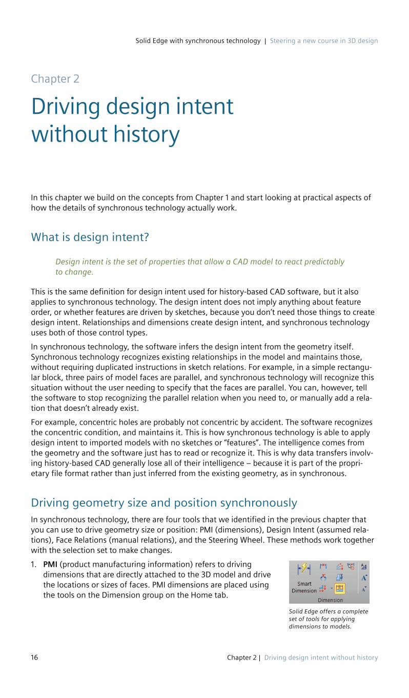
Solid Edge offers a complete set of tools for applying dimensions to models.
1. PMI (product manufacturing information) refers to driving dimensions that are directly attached to the 3D model and drive the locations or sizes of faces. PMI dimensions are placed using the tools on the Dimension group on the Home tab.
Chapter 2
Driving design intent without history

Solid Edge with synchronous technology | Steering a new course in 3D design
17 Chapter 2 | Driving design intent without history
Dimensions in Solid Edge® software have several colors indicating function or state:
a. Red = Locked. This means that you have to actively edit the dimension to change its value (the system cannot drive or change the value).
b. Blue = Unlocked. This means that you can change the dimension can manually or the system can change it through other changes in the model. You can use the Lock toggle on the dimension box to toggle dimensions between locked and unlocked states.
c. Purple = Read Only or For Reference. Can be a number of things, including Not To Scale or driven by table.
d. Orange = Highlighted
e. Green = Selected
f. Brown = Dangling, or detached dimensions that have lost one of their references
Note that the following only applies to PMI dimensions on the model, not to dimensions within sketches.
Within the dimensions are directional arrows (red 3D cylindrical arrows) that indicate which side of the dimension will move when you make a change: left, right, or symmetric. For example, if you did not yet set the direction of the dimension, and you click on the left side of the dimension to edit it, the left side moves. In the previous figure, notice the posi-tion of the cursor relative to the numerals and the resulting red arrows on the dimension.
Changing the design intent on the fly with the dimension directional arrows is something you will not find in history-based software.
This method of changing the direction of the dimension represents a major departure from how dimensions work in other CAD software. The dimension tools on their own add greatly to the design intent flexibility that synchronous technol-ogy gives you over other methods.
You can permanently set the direction of the dimension in the dimension dialog box, shown above. Once you do this, the side of the numeral that you click on no longer controls the direction of change.
2. Design Intent (formerly called Live Rules) refers to the interface Solid Edge uses to display and enable the user to control the assumed or inferred relations based on the current state of the model.
Design Intent essentially adds to your selection set anything that satisfies the enabled options. So if you select a cylindrical face to modify, the default settings will add any faces that are concentric or tangent to the selected face.
Faces selected by Design Intent apply to Steering Wheel edits as well as PMI edits. So the Steering Wheel will move the entire selection set which includes whatever you select manually plus

Solid Edge with synchronous technology | Steering a new course in 3D design
18 Chapter 2 | Driving design intent without history
whatever Design Intent selects for you based on the settings. PMI likewise will move the entire selection set plus Design Intent faces for any dimensional changes.
The idea for the two different panels (the gray one above and the colored tiles below) is that for most of your edits, you will not make any changes to the Design Intent settings, or the changes that you make will be to the simple, commonly used settings shown in the gray Design Intent panel. However, there will be those times when you need more detailed con-trol, and for those times, you can access the Advanced Design Intent panel, and get as detailed as you want, including the Solution Manager.
a. The Design Intent panel enables you to turn off the most basic assumed relations. To display more advanced relations, you can display the Advanced Design Intent panel, shown below.
Orange means the option is active, white means it is inactive.
b. The Advanced Design Intent panel enables you to turn off assumed relations, such as keep orthogonal to base planes, coplanar axes and consider sketch planes.
The symbols in the Advanced Design Intent panel are identified using tool tips, but here is a detailed list with the keyboard shortcuts for each listed in parentheses.
Design Intent Restore (R) – Restore default settings
Consider Reference Planes
Design Intent Save Relations (F) – Creates persistent relations for Design Intent settings
Consider Sketch Planes
Concentric (C) Consider Coordinate Systems
Parallel (L) Lock To Base Reference
Tangent (T) Same Radius
Tangent Touching (G) Keep Orthogonal to Base
Coplanar (P)Suspend Design Intent Settings
Perpendicular (J)
Symmetry About Base Planes (S) Relax Dimensions (D)
Symmetry about YZ (Y) Relax Persistent Relations (N)
Symmetry about ZX (Z) Solution Manager (V)
Local Symmetry (Ctrl-Y) Auto Solution Manager
Aligned Holes (A) – Coplanar axes of holes, Cylinders, revolved features
Design Intent Options
Aligned/Coplanar in XY (Q)
Aligned/Coplanar in YZ (W)
Aligned/Coplanar in ZX (E)
Aligned/Coplanar in canted planes (Ctrl-A)

Solid Edge with synchronous technology | Steering a new course in 3D design
19 Chapter 2 | Driving design intent without history
c. Solution Manager
The Solution Manager is a way to manage failure. When an edit will not work, you would typically adjust the Design Intent settings. If it continues to not work the way you want it to, you would resort to the Advanced Design Intent panel to control the Intent in a more detailed way.
If you still cannot get the edit to work, or if you just want to investigate the reasons why the model is behaving the way it does, the Solution Manager is the way to go. This can be used for either Steering Wheel or PMI edits.
We will do a quick overview of Solution Manager at the end of this chapter to show you that there is always a way to get the solution, and that there are reasons for your model acting the way it does. Below is the classic simplified model often used to demonstrate the functions.
3. Face Relations. Manually applied relations that work like sketch relations, but are applied directly to faces in the model.
a. Face Relations are listed in PathFinder.
b. Faces are tracked in PathFinder
c. You can repair/replace by right-clicking a listed face.
4. Steering Wheel. You can use the steering wheel to move (translate or rotate) faces that are not explicitly defined by any of the previously mentioned tools.
a. The combination of the current selection set and faces selected automatically by Design Intent determines which faces will be edited in a given operation. The selection set in essence replaces the history-based feature, but it is more flexible.
b. The Steering Wheel element that you choose to use (arrow or torus) determines whether the change will be a translation or rotation, respectively.
c. You can move the blue handles to determine the direction of translation or center of rotation.
d. Select the translucent disk to make a planar move.
e. You can move the starting point of the edit (blue dot), and drag to a keypoint to get a From/To type edit, or type in a value, or just drag to make the move.
Not changing
Selection set
Error path
Solved correctly
Isolated faces
Rigid set
Grounded
Relaxed

Solid Edge with synchronous technology | Steering a new course in 3D design
20 Chapter 2 | Driving design intent without history
From this information, we can summarize that with synchronous technology:
1. Design intent comes from the geometry.
2. Design intent can be changed on the fly.
3. Since design is not a linear task, the order of features is irrelevant.
TutorialsIn this chapter we talked a lot about concepts and thrown around a number of ideas. But in this tutorial, you will see for yourself some of the power of design intent in synchronous technology.
For this, and subsequent tutorials, you can get a 45-day trial of the current version of Solid Edge. This is available through downloading a local installation or streaming the full version over the internet.
Tutorial 1: Using PMI dimensions to change modelThis tutorial was created using Solid Edge ST8.
1. Start Solid Edge from your Windows Start Menu or from the icon on your desktop.
2. Click the Application button, in the upper left, click New and then select a part tem-plate with your choice of units.
Use a default template for now. We will set up custom templates for you in a later tutorial.
3. Choose Home tab –> Solids group –> Box .
The Box command creates a box primitive without requir-ing a sketch. For other shapes, you can sketch the shape and use the Extrude command.
4. Move the mouse over the base planes in the center of the display, and when the Top plane is highlighted, press F3 to lock your initial rectangle to that plane.
5. In the CommandBar, set Selection Type to by Center.
Note: Your CommandBar may not look like the one shown here. I am using the Maximum Assistance theme, which includes more text in the interface. The default CommandBar is docked horizontally at the top of the graphics window, and uses icons rather than text.
6. Click and release the left mouse button on the origin (Base), then move the cursor away from the origin.
Synchronous technology brings together the most
powerful tools in history-based
techniques with the most powerful tools in
Direct Modeling techniques to give you a full range of capabilities
to create whatever you need to create.

Solid Edge with synchronous technology | Steering a new course in 3D design
21 Chapter 2 | Driving design intent without history
7. Create the box, assigning actual dimensions, in a series of short steps:
a. Type 5.
b. Press Tab.
c. Type 4.
d. Press Tab.
e. Press Enter.
f. Move the cursor so the light blue solid appears in the positive Z direction.
g. Type 3.
h. Press Enter.
You could also simply drag with the cursor and click to accept dimensions visually.
The dimensions placed on the resulting solid are blue dimensions, which means that they are unlocked. You can change these dimensions manually by entering values or using the Steering Wheel.The system can automatically change the dimensions if another dimen-sion changes and requires values to change in order to solve properly.
8. In the images that follow, note that the red arrows on the 5.000 dimension value are point-ing in different directions, depending onthe cursor position on the dimension value. When the cursor is over the left or right side of the dimension value, the dimension changes on the left or right side of the block, respectively. When the cursor is in the middle of the number, the dimension changes symmetrically.
It may be easier to understand the correlation between the red arrows and the cursor posi-tion by trying it: move the cursor from the left of the dimension value to the right. Watch how the red arrows change.
9. When both red arrows are displayed, click the 5.000 value, in the middle.
The display of the red arrows on the screen is reflected by the selected option at the bottom of the value box (double ended green arrow highlighted in orange).
If you use your mouse scroll wheel, the gray solid changes symmetrically.

Solid Edge with synchronous technology | Steering a new course in 3D design
22 Chapter 2 | Driving design intent without history
10. Change the dimension value and lock the dimension by doing the following:
a. Type 7.5.
b. Click the lock icon to the right of the dimension value.
c. Press Enter.
The solid changes size symmetrically and the dimension turns red. Red dimensions are locked, meaning they can only be changed when you manu-ally type in a value.
11. Click the vertical 3.000 dimension.
12. To change the dimension so it will change on the positive Z side, click the green arrow that points to the left.
Do not lock the dimension.
13. Type 3.25 and then press Enter.
14. Click the top face of the box.
A white arrow is displayed on the top face. This is the steering wheel in a simplified form. The software assumes that if you just click a single flat face, you want to move that face.
15. Click the steering wheel arrow.
A value box is displayed on the model. You can just click to get a visual dimensional change or type in a value to get an exact differential value. The value that you type in here will add or subtract from the 3.250 dimension.
You changed this value in two ways: directly typing in a new value for the dimension and directly typing in a differential change amount for the dimension.
This was a blue (unlocked) dimension, which is what allowed the Steering Wheel to change it. The red 7.500 dimension cannot be changed by the Steering Wheel because it is locked.

Solid Edge with synchronous technology | Steering a new course in 3D design
23 Chapter 2 | Driving design intent without history
Tutorial 2: Design intent and solution manager overviewNow you’ve used simple dimensional changes and been introduced to a simple Steering Wheel change coupled to an unlocked dimension.
You can follow this tutorial either in print or the linked video.
1. Open the file from the folder for this chapter called “tutorial2 start.par”.
2. Click on the face highlighted green in the image to the right.
3. Click on the Steering Wheel arrow and drag it back and forth.
Notice the lower ear also moves. To prevent this from happening (or to cause it to happen if it’s not happening) remove the check from in front of the Coplanar option in the Design Intent panel.
4. Remove about a half inch of material, using the number in the white box as a guide, then click the left mouse button to accept the change.
5. Next let’s make a change that you might have to think hard how to do it in ordered, but in Synchronous it becomes easy.
Let’s take the hole on the top ear and angle it in the YZ plane. Another way to think about it is to rotate the hole about a line parallel to the X axis.
To get started, select the inside face of the top hole, as shown. You may notice that you are getting the simplified Steering Wheel instead of the full wheel shown to the right. To get the full Steering Wheel, click on the big blue ball at the center and just drag it away, then drag it back to the edge of the hole, and it will snap to the center, and display the third axis as well as the torus and the tool plane.
Also notice that as shown, you cannot get the rotation you want. We want to rotate about X, and the Steering Wheel is currently oriented to rotate about Y. To rotate the Steering Wheel, Shift-click on the tool plane (blue translucent disk coplanar with the torus).
Note that when you select a hole or cylindrical cut, the Steering Wheel allows you to move or rotate the hole, but you cannot use the Steering Wheel to resize the hole. Selecting a hole brings up a diameter dimension which can be used to resize.
6. Now you can click on the torus and angle the hole as well as the cylindrical outer face together. Play around with this to get the feel for what you can do with the torus. This is a type of edit that you may not even consider doing in ordered modeling. Also remember that it is completely valid to use normal methods to create something and then edit it to achieve an orientation in which it may have been more difficult to create.
7. When you are done, use Ctrl-Z (undo) to return the model to its previous state.
Ctrl-Z in Solid Edge works to undo until you save the model. You cannot undo functions previous to a save.

Solid Edge with synchronous technology | Steering a new course in 3D design
24 Chapter 2 | Driving design intent without history
8. If you use the Steering Wheel to move in the X direction, you will find that the entire model moves. This is because no faces have been grounded, and the “Lock to Base Reference” Design Intent option is turned off.
Let’s first turn on that option, test it, and then ground some faces.
9. With the hole face selected, click on the Advanced… option on the Design Intent panel.
10. Click on the Lock to Base Reference option so that it turns orange. Now try to move the hole in the X direction again. Notice the end radius on the ear gets bigger as you move the hole in the X direction because the face is tied to the end of the part that was just locked down with the Lock to Base Reference Design Intent option.
Next select the tool plane and move the hole in the XZ plane. This is just to get used to edit-ing with the Steering Wheel, and the Design Intent options.
Finally, return the model to its original state with Ctrl-Z, and turn off the Lock to base option in the Design Intent panel. If you have deselected all model faces, you may have to reselect a face to gain access to the Design Intent panel again, as it only appears when geometry is selected and ready to edit.
11. Next let’s lock down some faces, but first we have to reposition the model with respect to the origin.
Rotate the model so you can see the back face, then drag a box around the entire part, and move the Steering Wheel to the bottom hole, as shown to the right.
We are going to reposition the part so that the Origin in on the back face, and then lock down all faces that are on the base planes.
12. Click on the Steering Wheel arrow that is parallel to the hole axis. This enables us to move the entire model along the Y axis.
Move the cursor to the Origin and click the Origin keypoint, as indicated in the screen shot below. This moves the entire part body along the Y axis so that the back face is on the XZ plane.
This technique for moving items will be very handy as you use the software.
13. Press ESC to clear the selection.
14. On the Ribbon, Home tab, Face Relate group, click on the Ground tool.

Solid Edge with synchronous technology | Steering a new course in 3D design
25 Chapter 2 | Driving design intent without history
15. Next, select the three faces shown in the image to the right, and click Accept on the Command Bar.
You will not have to hold down the Ctrl key to select multiple faces while the Ground function is active.
Note that for these screen captures, I am using the Maximum Assistance theme, which adds more text to the Command Bar and orients it vertically instead of the default horizontal Command Bar. This setting can also be accessed independently from the themes using the Application Menu, Solid Edge Options, Helpers, Command User Interface, Use vertical docking window form.
Note also that the face relationships are stored in the PathFinder, as shown to the right. Very easy to remember what you’ve applied to the model. Faces highlight when you mouse over the relation.
16. Now we will move on to using the Solution Manager, which was mentioned earlier in this chapter. The Solution Manager helps you sort out which relationships are causing a particular
edit to not work as expected. It also helps you visualize differ-ent solutions to the problem by analyzing the error path, and relaxing one of the overconstrained links connected to the face you tried to edit.
Select the end face of the model, as shown, and drag the Steering Wheel arrow out from the model. This edit is failing for reasons we are about to research.
Finding out why things happen is an important way to understanding how things work and what you should reasonably be able to expect your tools to do. A few extra minutes spent researching problems from time to time will build your skills and knowledge of the software significantly.

Solid Edge with synchronous technology | Steering a new course in 3D design
26 Chapter 2 | Driving design intent without history
17. Click to place the face about an inch from the original. Notice how the model again turns colors.
The colors, from top to bottom, are:
Transparent = irrelevant Green = selected Orange = error path Blue = solves correctly Red = isolated (rules off) Purple = rigid set Black = grounded Slate = rules relaxed
The colors that you are concerned about here are the orange faces. As a history-based user, you can think of all the orange faces being overconstrained. Orange is the “error path” color. Think of the path as a chain where each dimension, face relation, or Design Intent assumption is a link, and you have to decide which link to relax, or break in order to allow your edit to work.
The way to examine the links in the chain is with right mouse button clicks and hovering with your mouse. For example, I can see that the fillet face is part of the error chain because it is orange. Notice that the 2.577 dimension is orange, because it is also part of the problem.
When you right click on the fillet face, the Solution Manager shows the set of relation icons to the right. The yellow triangle means that relation is part of the error chain, so the tangent between the fillet and the top flat face is not part of the problem.
This tells you that the fillet face has three Design Intent assumptions, and hovering your mouse over the icons will highlight the two faces involved in each relation. So hovering over the Concentric icon highlights the fillet face and the hole.
If you click on one of the icons, it will go gray and break that relation temporarily, and show what the model would look like with that relation broken. Clicking on the Concentric relation breaks the error chain, and fixes the edit error.
To put the model back the way it was, click on the gray icon again to reactivate it and show the model in its error state again.
18. Click the right mouse button again to hide the icons, and then right click on the face of the hole. This brings up the concentric icon as well as a dimension icon. If you click the dimen-sion icon, it goes gray, and the Solution Manager turns the 2.577 dimension to an unlocked (blue) dimension, meaning that the edit would drive the dimension. This also solves the problem , but in such a way that the hole moves to match the fillet.

Solid Edge with synchronous technology | Steering a new course in 3D design
27 Chapter 2 | Driving design intent without history
19. Accept this result by clicking on the green checkmark in the Advanced Design Intent.
You may also want to watch the video associated with this tutorial. It does not follow the steps exactly, but shows some additional techniques.
There are a few things here to remember, but with all of the symbols decoded and the ways to access the information spelled out, the Solution Manager is accessible. With the Solution Manager as a safety net, you can feel more secure in exploring more synchronous edits, and feeling better about the idea that synchronous really works backwards from the “fully con-strained” concept. Nothing is going to move unless you allow it, which is the reverse of the basic history-based concept which is everything can move unless you constrain it.

Solid Edge with synchronous technology | Steering a new course in 3D design
28 Chapter 2 | Driving design intent without history
SummaryIn this chapter you learned some of the practical details of how synchronous technology edits parts. From PMI to Face Relations to the Steering Wheel and Design Intent with the Solution Manager, you are in control of how your model reacts to change. And changing how it reacts to change is far easier than with history-based modeling. Even troubleshooting overdefined rela-tionships has a clear and understandable pathway to success.
© 2016 Siemens Product Lifecycle Management Software Inc. Siemens and the Siemens logo are registered trademarks of Siemens AG. Solid Edge is a registered trademark of Siemens Product Lifecycle Management Software Inc. or its subsidiaries in the United States and in other countries. Autodesk and Inventor are registered trademarks or trademarks of Autodesk, Inc., and/or its subsidiaries and/or affiliates in the USA and/or other countries. Creo is a trademark or registered trademark of PTC Inc. or its subsidiaries in the U.S. and in other countries. Pro/ENGINEER is a trademark or registered trademark of PTC Inc. Microsoft and Microsoft Office are registered trademarks of Microsoft Corporation. SolidWorks is a registered trademark of Dassault Systèmes SolidWorks Corporation. All other logos, trademarks, registered trademarks or service marks belong to their respective holders.

Solid Edge with synchronous technology | Steering a new course in 3D design
29 Chapter 3 | Introduction to Solid Edge
The Solid Edge® software interface follows Microsoft’s standards. Most functions and interface elements will be familiar to most Windows users. You can customize the interface manually or use one of the pre-established Themes that use commonly used groups of settings that different types of users look for.
The Solid Edge workflow, or order of operations is often unique to Solid Edge and doesn’t follow conventions from other CAD packages. When learning Solid Edge, it is best not to expect it to work exactly like some other system. The general concepts are usually familiar to users of other software packages, but the details of how you accomplish specific tasks are often different. Terminology is often unique to each system as well.
Solid Edge interfaceLet’s continue by identifying the major parts of the Solid Edge interface.
Additional panes can be turned on or off using the View >Show > Panes dropdown list. All of these panes can be docked, or moved around the screen, and even outside of the Solid Edge application window to put them on a separate monitor. Initially, when learning Solid Edge, you will use the Learn Solid Edge pane frequently. The Prompt Bar is important for new and learning users. You will use the Select pane frequently to create and modify features. The rest of the panes come up on an as-needed basis, however I would recommend the YouTube pane for new users who might want to ask questions using video.
Chapter 3
Introduction to Solid Edge

Solid Edge with synchronous technology | Steering a new course in 3D design
30 Chapter 3 | Introduction to Solid Edge
Note: The Solid Edge User Community is a great place to ask questions and get answers about the software. You need a login to ask questions, but you can read what other people have written without a login. Give it a try: https://community.plm.automation.siemens.com/t5/Solid-Edge-User-Community/ct-p/solid-edge
CustomizationEveryone has a different way of working, and everyone has different desires when it comes to how they use the software interface. Because of these differences, every user has different needs from customiza-tion. If you’re using Solid Edge eight hours a day, getting things set up properly can save you a lot of time. Some users just want the interface organized in a certain way. Some experts are looking for speed, some who are still learning the software may need to make things easy to find.
Still other goals for customization might be efficient use of space, total number of clicks to accomplish a task, total amount of mouse travel, or having all the tools you might use available when you need them. Some companies even require that all users use the same interface setup. Whatever your goals, realize that there are probably conflicting ideas that you have to balance out. For example, the default Solid Edge interface settings are very space efficient, but you have to be well acquainted with the interface in order to use it that way. On the other hand, if you use the Command Bar with all of the text labels on it, that makes it easy to find things when you’re not sure what you’re looking for, but it also takes up a lot of space. Keyboard shortcuts can be accessed with no visual interface, but require keystrokes and memorization. Radial menu requires two keystrokes for every command, and is limited in the number of commands it can contain.
ThemesJust be aware that there are always trade-offs, and each decision requires a balance of poten-tially conflicting factors. This is part of the idea behind the Solid Edge Themes. Solid Edge Themes are out-of-the-box customizations aimed at the needs of different kinds of users.
Solid Edge with synchronous technology | Steering a new course in 3D design
31 Chapter 3 | Introduction to Solid Edge
Examples of the Themes are:
• Some Assistance – For users who are partially familiar with the interface and workflow, but still need a hint from time to time.
• Maximum Assistance – This is for beginners who are working through tutorials or attending classes, and aren’t yet familiar with the Solid Edge workflow and tool icons. (This is the theme used for most of the screenshots in this book).
• Maximum Workspace – This option is primarily for expert users who can identify each icon by sight, and don’t need tool tips.
• Balanced – This is the default Solid Edge settings which are most useful for users with more than a year using Solid Edge.
You can set a theme, customize it, and then save the customized theme to a different name. You can even move the theme to other computers or other installations of Solid Edge on the same computer.
Customization is available from the drop down on the Quick Access toolbar at the top left of the screen. The various toolbar areas are listed as tabs in the Customize dialog, and the entire list of commands is available in the window on the left. You can use the Add and Remove buttons between the left and right windows to customize each interface element. Use separators, spac-ers and the Move Up and Move Down buttons to organize your buttons in a way that fits your workflow or tool search style.
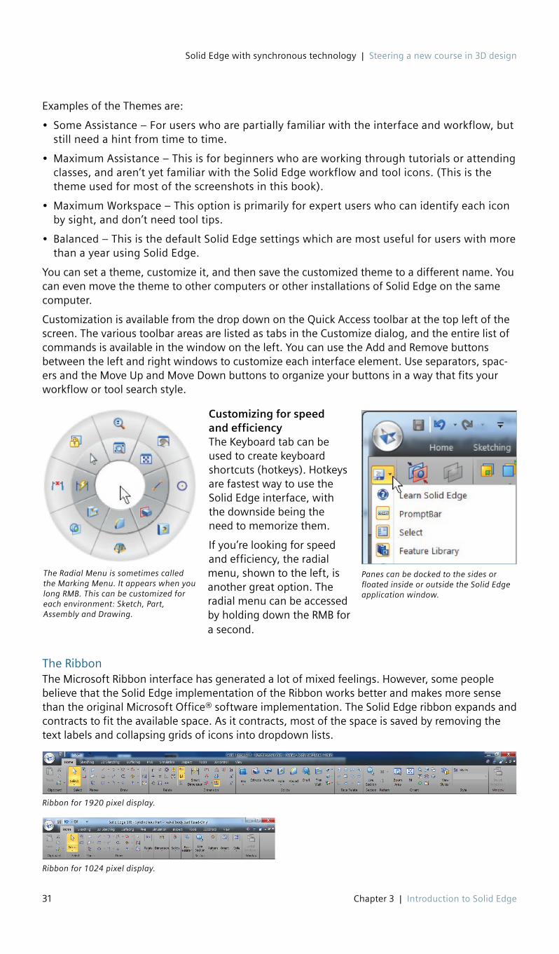
Customizing for speed and efficiencyThe Keyboard tab can be used to create keyboard shortcuts (hotkeys). Hotkeys are fastest way to use the Solid Edge interface, with the downside being the need to memorize them.
If you’re looking for speed and efficiency, the radial menu, shown to the left, is another great option. The radial menu can be accessed by holding down the RMB for a second.
The RibbonThe Microsoft Ribbon interface has generated a lot of mixed feelings. However, some people believe that the Solid Edge implementation of the Ribbon works better and makes more sense than the original Microsoft Office® software implementation. The Solid Edge ribbon expands and contracts to fit the available space. As it contracts, most of the space is saved by removing the text labels and collapsing grids of icons into dropdown lists.
Ribbon for 1920 pixel display.
Ribbon for 1024 pixel display.
The Radial Menu is sometimes called the Marking Menu. It appears when you long RMB. This can be customized for each environment: Sketch, Part, Assembly and Drawing.
Panes can be docked to the sides or floated inside or outside the Solid Edge application window.

Solid Edge with synchronous technology | Steering a new course in 3D design
32 Chapter 3 | Introduction to Solid Edge
You can switch between the tabs by clicking on them or by pressing Alt and then pressing one of the keyboard shortcut keys that appear. Notice that the shortcuts are on the Quick Access bar and Application menu as well as the Ribbon tabs.
Pressing the Alt key causes shortcuts to the tabs to appear.
ToolTipsOne easy way to get help about the interface quickly is to use ToolTips. You can access ToolTips by hovering the mouse over buttons in the interface. Solid Edge has three types of ToolTips, which you can control in Solid Edge Options (Application menu > Solid Edge Options > Helpers> Command Buttons):
1. Basic
Basic ToolTips show the tool’s icon, its name, and a brief description of what it does.
2. Enhanced
Enhanced ToolTips include the basic ToolTips plus some general tips on usage and an image that acts as a visual aid.
3. Video clips
The Video clips ToolTips looks like the Enhanced, but in place of the static image, there is a brief animated image showing the tool in use.
For beginning users, the Video clips ToolTips are really a great idea. Very often all you need is that brief description of how the tool works in words, and then a video to show it in action to get you moving. General help often lacks important details like where to find something or if there are any prerequisites for a particular function, and some-times you can find this sort of thing in the ToolTips.
Command FinderAnother type of help that you can make use of for help with the interface is the Command Finder at the bottom of the screen. Just type in the name of the command that you are looking for in the box, and Command Finder pops open a window with a list of related commands.
You can also tell it to look for commands that are outside of the current environment. For exam-ple, if you search for center mark, and are in the Part environment, Command Finder might return a list of tools that contain the word “center” or “mark” in their names or descriptions, but

Solid Edge with synchronous technology | Steering a new course in 3D design
33 Chapter 3 | Introduction to Solid Edge
the actual “center mark” tool is found in the Draft envi-ronment. If you look at the bottom of the Command Finder window, you will see an option to click for “Show matches outside of Environment”, and these matches will be shown in a lighter gray font. If there are not matches outside of the environment or you have already clicked that option, the option will not appear. Choices that are grayed out will not flash to show you where they are, because they cannot be accessed in the current environment.
In the returned list, mouse over your choice of com-mands, and the Ribbon changes to show you where the command is and the button flashes. When you are done with Command Finder, the Ribbon stays in the configura-tion where you can find the command you were searching for.
WorkflowWorkflow, in this context, means order of operations. Most of the Solid Edge interface works with the “Action => Object” workflow paradigm, where you select the tool you want to use, and then select what you want to use the tool on. An example of this is the workflow to create a sketched extruded feature. The workflow is shown here for both Synchronous and Ordered:
1. Synchronous
a. Click sketch tool
b. Select plane or planar face
c. Create sketch (click-click method, not click-drag)
d. Click on the Extrude tool button
e. Select closed region/chain
f. Right click to accept extrude region
g. Set to add or remove material/other options
h. Drag a distance or key in a value
2. Ordered
a. Click Extrude (or Cut)
b. Select existing sketch or a plane to make a new sketch on
c. Draw sketch (click-click)
d. Close sketch
e. Drag or key in distance/set options
f. Right click to Finish
g. Click Cancel to avoid making another extrude
You can also use variations of some of these steps, but these are the commonly used workflows for these features.
Other popular CAD packages enable you to select the plane, the sketch or the feature button in different orders, but Solid Edge wants you to follow the process.
The Command Finder can help you find tools in the interface, but also can help you find equivalent terms from other CAD systems

Solid Edge with synchronous technology | Steering a new course in 3D design
34 Chapter 3 | Introduction to Solid Edge
I mentioned that the preferred workflow is Action => Object, but there are times when the requirements are the opposite. For example, when you make a mirror or pattern in Synchronous mode, you must have geometry selected before the Mirror or Pattern tools become available. When creating mates, you select the mate tool first, then the geometry.
In general, although there may be a couple of exceptions, Solid Edge requires that you proceed one way or the other, but does not allow you to select tools or items in random order. This aspect of the workflow in Solid Edge can be difficult for SolidWorks® software users to accommodate.
The most important thing to keep in mind when learning a new CAD system is that you will be most successful if you learn the new system in the way it is meant to be used. Trying to force the new system to work like another system generally leads to frustration and failure. Solid Edge has a full complement of tools, but it does not work exactly like SolidWorks. Take this bit of advice from someone with 17 years of SolidWorks experience who changed to Solid Edge. Learn Solid Edge on its own terms. You will not always find a direct comparison between functions in the two systems.
SettingsMost of Solid Edge settings are located in the Solid Edge Options dialog found at the bottom of the Application Menu. Most of the settings in this box are global, meaning they apply to any document opened on the current computer. There are some settings in here that are document specific, however. These settings will travel with the file (or template) they are saved with.
It may be a good idea for new users to browse through the Solid Edge Options dialog to become familiar with some of the settings you can control easily.
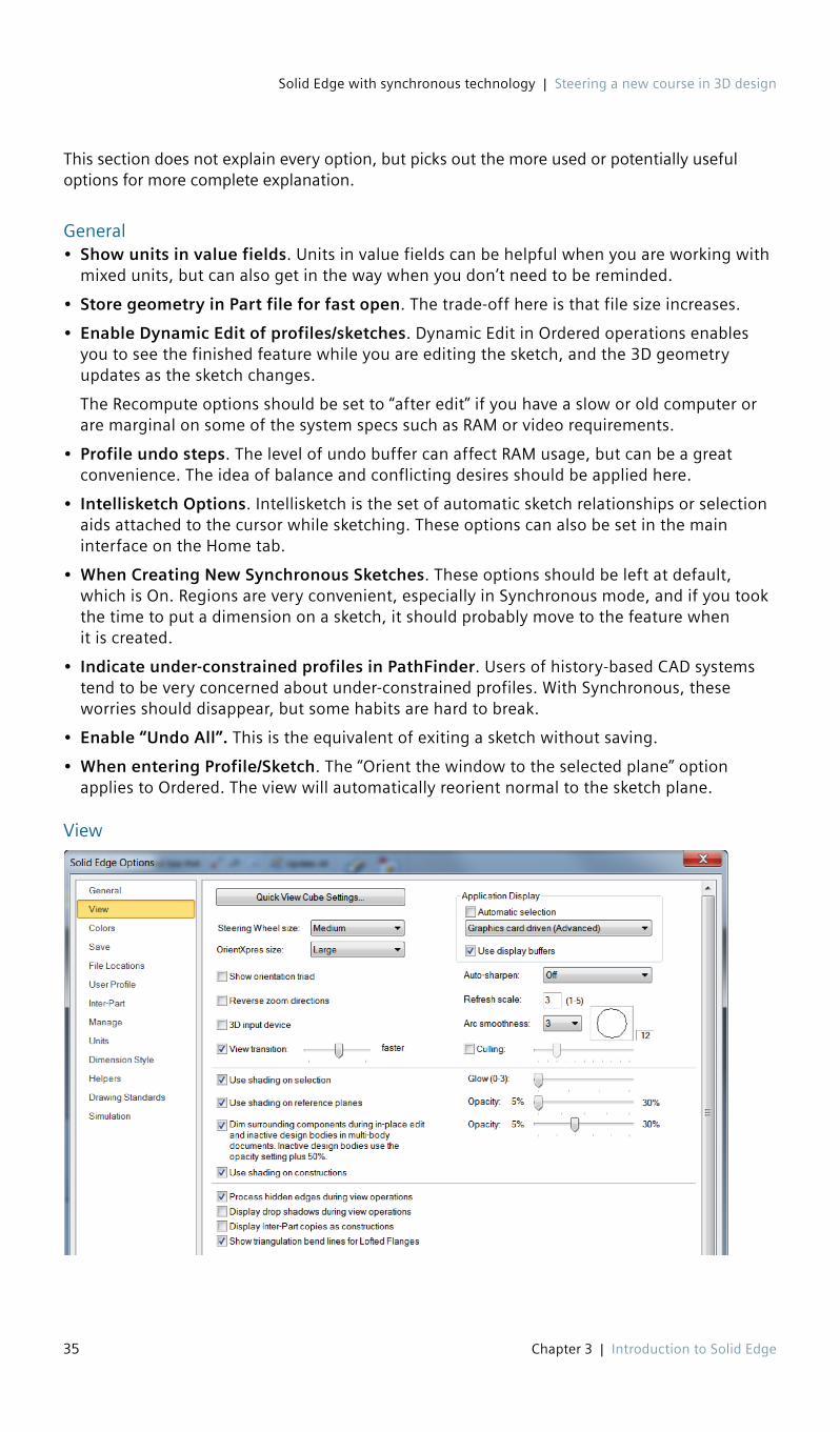
Solid Edge with synchronous technology | Steering a new course in 3D design
35 Chapter 3 | Introduction to Solid Edge
This section does not explain every option, but picks out the more used or potentially useful options for more complete explanation.
General• Show units in value fields. Units in value fields can be helpful when you are working with
mixed units, but can also get in the way when you don’t need to be reminded.
• Store geometry in Part file for fast open. The trade-off here is that file size increases.
• Enable Dynamic Edit of profiles/sketches. Dynamic Edit in Ordered operations enables you to see the finished feature while you are editing the sketch, and the 3D geometry updates as the sketch changes.
The Recompute options should be set to “after edit” if you have a slow or old computer or are marginal on some of the system specs such as RAM or video requirements.
• Profile undo steps. The level of undo buffer can affect RAM usage, but can be a great convenience. The idea of balance and conflicting desires should be applied here.
• Intellisketch Options. Intellisketch is the set of automatic sketch relationships or selection aids attached to the cursor while sketching. These options can also be set in the main interface on the Home tab.
• When Creating New Synchronous Sketches. These options should be left at default, which is On. Regions are very convenient, especially in Synchronous mode, and if you took the time to put a dimension on a sketch, it should probably move to the feature when it is created.
• Indicate under-constrained profiles in PathFinder. Users of history-based CAD systems tend to be very concerned about under-constrained profiles. With Synchronous, these worries should disappear, but some habits are hard to break.
• Enable “Undo All”. This is the equivalent of exiting a sketch without saving.
• When entering Profile/Sketch. The “Orient the window to the selected plane” option applies to Ordered. The view will automatically reorient normal to the sketch plane.
View

Solid Edge with synchronous technology | Steering a new course in 3D design
36 Chapter 3 | Introduction to Solid Edge
• Quick View Cube, Steering Wheel and OrientXpress. The size settings for these visual aids control how visible and selectable the on-screen elements are. Also controls how much space they take up on the screen.
• Auto-sharpen. This controls how closely Solid Edge approximates curves. When the arc smoothness is low, circles can look like hexagons. The better the curves look, the harder your video card will have to work to keep up.
• Use shading on selection. If this is off, a selected face will only show the edges high-lighted. With it on, the entire face will highlight orange when you mouse over it and green when you select it. The same settings apply to reference planes and constructions (surface bodies).
Colors
I would recommend that you leave the default colors alone. But notice that you can access the Background/View Overrides from this page. These are document specific settings which you can save with your templates. You can also access those settings by right clicking in blank space inside a part or assembly document.
Save
These settings are for automatic save and backup.

Solid Edge with synchronous technology | Steering a new course in 3D design
37 Chapter 3 | Introduction to Solid Edge
File Locations
To change one of the file locations, double click on the path and then browse to the new location. Locations that might be important to control shared documents or documents used between versions of Solid Edge are:
• Solid Edge admin options• Custom settings file• Macros• Property seed file• User templates• Tolerance tables• Sheet metal gage file• Holes database
Inter-Part
In Solid Edge, you can specify which types of Inter-Part (in-context) relations users can create. These are the relations that create associative links between parts in an assembly.

Solid Edge with synchronous technology | Steering a new course in 3D design
38 Chapter 3 | Introduction to Solid Edge
Units
Units are probably better set up as template-driven settings. You also need to be aware of the role Dimension Styles play in controlling units, standards, and dimensioning before deviating too far from the default settings.
Dimension Style
Helpers
The Helpers page is where you will find many useful interface settings.
• Start using this template/Start with my last saved document. When this is set, a new session of Solid Edge will automatically start with a new document using the specified tem-plate. This is very useful if you start your day making parts, or if you work on one part for a number of days in a row. Set to None to disable.
• Start Part and Sheet Metal documents using this environment. Are you a fan of Synchronous? A hold-out for Ordered? You can always start your parts in the same mode with this setting.

Solid Edge with synchronous technology | Steering a new course in 3D design
39 Chapter 3 | Introduction to Solid Edge
• Edit Creation Options. You can remove extraneous templates from the Startup list to increase your efficiency.
• Set Default Templates. Most Solid Edge users have specific templates that they prefer for each type of document. This setting allows you to select which templates are used as defaults for each type of document.
• Show PathFinder in the document view. When this setting is ON, the PathFinder appears as an overlay in the graphics window. With the setting OFF, the PathFinder is put into a separate dockable pane. In the image on the left below, the setting is OFF, the image on the right has the setting turned ON.
• Show command tips. Command tips are similar to ToolTips, but show up right in the graphics window while you are working. They show up as dismissable text bubbles from which you can access additional help. For brand new users these can be helpful. Resetting them and revis-iting them may also be helpful to get a refresher on some of the workflow and terminology.
• Show basic tooltips/enhanced tooltips/video clips. The display and types of tooltips is dis-cussed earlier in this chapter.
• Increase buttons on Command Ribbon by 2x. This shows the relative size difference when using the Increase 2X setting. Notice other text in the interface is also increased, including the PathFinder text.

Solid Edge with synchronous technology | Steering a new course in 3D design
40 Chapter 3 | Introduction to Solid Edge
• Use horizontal toolbar form/vertical docking window form. This setting refers to the Command Bar, and is one of the items controlled by Themes. The horizontal setup is very compact, but primarily for experienced users. Because you’ll have to use tooltips to know what the various buttons are for. The vertical setup takes up a lot of space, but it contains text so you know what most of the buttons are for. Plus, the vertical setup is going to look more famil-iar to SolidWorks PropertyManager users. Below are both interfaces for the same Extrude function.
Again we see the tradeoff between usable graphics space and con-venience of knowing what the buttons do.
• Radial Menus. The radial menu can be accessed by holding the RMB down for longer than the designated period in milliseconds or by dragging the RMB in the direction of one of the commands on the radial menu disk (gesture). With touch interfaces, the gestures are use-ful. In more desktop oriented setups with mouse and keyboard, the RMB delay may be the preferred method.
• Advanced Design Intent Panel. Design Intent Panel was formerly called Live Rules. The basic Design Intent panel is shown here to the right. This is new with ST8, for those of you familiar with previous versions.
The advanced Design Intent Panel is shown below, and can be rotated vertically. Using this Solid Edge Option.
This is another example of the choices Solid Edge gives users for a sleeker, icon-driven interface, or a more explanatory icon-and-text-driven interface.
• Document Name Formula. You can use available document properties to automatically build a filename for your new documents.
A video demonstration exists that goes along with the material in the chapter. Click on this link to view it.

Solid Edge with synchronous technology | Steering a new course in 3D design
41 Chapter 3 | Introduction to Solid Edge
SummaryThe Solid Edge interface follows Microsoft standards and is highly customizable. You can apply themes to it to make it appropriate for various levels of user. The interface is also flexible enough to be useful on a variety of devices, although you will probably find that as a professional CAD product, it is best used on large monitors.
© 2016 Siemens Product Lifecycle Management Software Inc. Siemens and the Siemens logo are registered trademarks of Siemens AG. Solid Edge is a registered trademark of Siemens Product Lifecycle Management Software Inc. or its subsidiaries in the United States and in other countries. Autodesk and Inventor are registered trademarks or trademarks of Autodesk, Inc., and/or its subsidiaries and/or affiliates in the USA and/or other countries. Creo is a trademark or registered trademark of PTC Inc. or its subsidiaries in the U.S. and in other countries. Pro/ENGINEER is a trademark or registered trademark of PTC Inc. Microsoft and Microsoft Office are registered trademarks of Microsoft Corporation. SolidWorks is a registered trademark of Dassault Systèmes SolidWorks Corporation. All other logos, trademarks, registered trademarks or service marks belong to their respective holders.