Embed Size (px)
Citation preview

www.danfoss.com/ir
MAKING MODERN LIVING POSSIBLE
Technical brochure
Solenoid valvesEVRA 3 40 and EVRAT 10 20

Technical brochure Solenoid valves type EVRA 3 to 40 and EVRAT 10 to 20
2 DKRCI.PD.BM0.B2.02 - 520H0120 © Danfoss A/S (AC- SMC / MWA), 11 - 2010
Contents Page
Introduction ........................................................................................................................................................................... 3
Approvals ................................................................................................................................................................................ 3
Technical data ....................................................................................................................................................................... 3
Ordering .................................................................................................................................................................................. 4
Flanges ..................................................................................................................................................................................5-6
Liquid capacity ...................................................................................................................................................................... 7
Suction vapour capacity .................................................................................................................................................8-9
Hotgas capacity ............................................................................................................................................................10-15
Construction/ Function ...................................................................................................................................................16
Material specification .......................................................................................................................................................17
Dimensions and weight.............................................................................................................................................18-19

EVRA 3 0.00 21 25 14 –40 → 105 42 0.23EVRA 10 0.05 21 25 18 –40 → 105 42 1.5EVRAT 10 0.00 14 21 16 –40 → 105 42 1.5EVRA 15 0.05 21 25 18 –40 → 105 42 2.7EVRAT 15 0.00 14 21 16 –40 → 105 42 2.7EVRA 203) 0.05 21 25 13 –40 → 105 42 4.5EVRA 204) 0.05 19 21 16 –40 → 105 42 4.5EVRAT 20 0.00 14 21 13 –40 → 105 42 4.5EVRA 25 0.20 21 25 14 –40 → 105 42 10.0EVRA 32 0.20 21 25 14 –40 → 105 42 16.0EVRA 40 0.20 21 25 14 –40 → 105 42 25.0
EVRA 3 21.8 4.6 4.3 3.2 6.5 2.1 1.7 1.7
EVRA/T 10 142.0 30.2 27.8 21.1 9.0 3.4 2.5 3.1 42.6 13.9 11.0 11.3
EVRA/T 15 256.0 54.4 50.1 38.0 16.1 6.2 4.4 5.5 76.7 24.9 19.8 20.3
EVRA/T 20 426.0 90.6 83.5 63.3 26.9 10.3 7.3 9.2 128.0 41.5 32.9 33.9
EVRA 25 947.0 201.0 186.0 141.0 59.7 22.8 16.3 20.4 284.0 92.3 73.2 75.3
EVRA 32 1515.0 322.0 297.0 225.0 95.5 36.5 26.1 32.6 454.0 148.0 117.0 120.0
EVRA 40 2368.0 503.0 464.0 351.0 149.0 57.0 40.8 51.0 710.0 231.0 183.0 188.0
Technical brochure Solenoid valves, type EVRA 3 to 40 and EVRAT 10 to 20
© Danfoss A/S (AC-SMC /MWA), 11 - 2010 DKRCI.PD.BM0.B2.02 - 520H0120 3
Introduction EVRA is a direct or servo operated solenoid valve for liquid, suction and hot gas lines with ammonia or fluorinated refrigerants.EVRA valves are supplied complete or as separate components, i.e. valve body, coil and flanges can be ordered separately.EVRAT is an assisted lift, servo operated solenoid valve for liquid, suction and hot gas lines with ammonia and fluorinated refrigerants.EVRAT is specially designed to open - and stay open - at a pressure drop of 0 bar. The EVRAT solenoid valve is thus suitable for use in all plant where the required opening differential pressure is 0 bar.EVRAT is available as components, i.e. valve body, flanges and coil must be ordered separately. EVRAT 10, 15 and 20 all have spindle for manual operation.
Approval DNV, Det Norske Veritas, NorwayP Polski Rejestr Statków, Poland MRS, Maritime Register of Shipping, Russia Pressure Equipment Directive (PED) (97/23/EC)(EVRA 32 and 40 CE marked according to PED) UL listed with GP coils
Technical data RefrigerantsR 717 (NH3), R 22, R 134a, R 404A, 410 A, R 744 (CO
2),
R 502 etc.
Temperature of medium−40 → +105°C. Max. 130°C during defrosting.
Ambient temperature andenclosure for coilSee “Coils for solenoid valves”, RD.3J.E2.02.
1) Rated liquid and suction vapour capacity is based on evaporating temperature te = -10°C, liquid temperature ahead of valve tl = +25°C, and pressure drop across valve ∆p = 0.15 bar.
Rated hot gas capacity is based on condensing temperature tc = +40°C, pressure drop across valve ∆p = 0.8 bar, hot gas temperature th = +65°C, and subcooling of refrigerant ∆tsub = 4 K.
Type
Opening differential pressure with standard coil ( ∆p bar)
Temperatureof medium
°C
Max. workingpressure
PB
bar
kv-value1)
m3/hMin.
Max. (= MOPD) liquid 2)
10 W a.c. 12 W a.c. 20 W d.c.
TypeRated capacity 1) [kW]
Liquid Suction vapour Hot gasR717 R22 R134a R404A R717 R22 R134a R404A R717 R22 R134a R404A
1) The kv value is the water flow in m3/h at a pressure drop across valve of 1 bar, ρ = 1000 kg/m3.2) MOPD for media in gas form is approx. 1 bar greater.3) For a. c. only4) For a. c. / d.c.

EVRA 3 032F3102 032F3103
EVRA 10 032F6207 032F6208
EVRA 10 032F6212 032F6213
EVRA 15 032F6217 032F6218
EVRA 20 032F6222 032F6223
EVRA 32 1 1/4 in. 042H1126
EVRA 32 1 ½ in. 042H1131
EVRA 32 1 1/4 in. 042H1140
EVRA 32 1 ½ in. 042H1141
EVRA 40 1 ½ in. 042H1128
EVRA 40 2 in. 042H1132
EVRA 40 1 ½ in. 042H1142
EVRA 40 2 in. 042H1143
Technical brochure Solenoid valves type EVRA 3 to 40 and EVRAT 10 to 20
4 DKRCI.PD.BM0.B2.02 - 520H0120 © Danfoss A/S (AC- SMC / MWA), 11 - 2010
Ordering Complete valves without flanges
Type Connection Code no. 1)
10 W coil with 1 m cable 10 W coil with terminal box
Valves without manual operation
Valves with manual operation
See table “Flange set”
See table “Flange set”
1) Valve body with gaskets, bolts and 10 W a.c. coil. Please specify code no., voltage and frequency. Voltage and
frequency can also be given in the form of an appendix number, see table “Appendix numbers”, under EVR.
Separate valve bodies
Type ConnectionRequiredcoil type
Code no.
EVRA 10
See table “Flange set”
a.c./d.c. 032F6210
EVRAT 10 a.c./d.c. 032F6214
EVRA 15 a.c./d.c. 032F6215
EVRAT 15 a.c./d.d. 032F6216
EVRA 20 a.c. 032F6220
EVRA 20 a.c./d.c. 032F6221
EVRAT 20 a.c./d.c. 032F6219
EVRA 25 a.c./d.c. 032F6225
EVRA 3See table
“Flange set”
a.c./d.c. 032F3050
EVRA 10 a.c./d.c. 032F6211
EVRA 25 a.c./d.c. 032F6226
TypeButt weld connection
Code no.DIN ANSI
Valves with manual operation
Valves without manual operation
Separate valve bodies with butt weld connections
Valves with manual operation
Coils See “Coils for solenoid valves”, RD.3J.E3.02.
AccessoriesStrainer FA for direct mounting, see “FA”, RD.6C.A3.02
Flanges, see the following pages.
ExampleEVRA 15 complete valve with terminal box, 220 V, 50 Hz, code no. 032F6218+ 3/4 in. weld flange set, code no. 027N1120.
ExampleEVRA 15 valve body with manual operation, code no. 032F6215+ 3/4 in. weld flange set, code no. 027N1120+ coil with terminal box, 220 V, 50 Hz,code no. 018F6701

D
mm
D
in.
d1
mm
d1
in.
d2
mm
d2
in.
L
mm
L
in.
L1
mm
L1
in.
L2
mm
L2
in.mm in.
10 3/8 18 0.709 10 0.394 14 0.551 32.5 1.280 3 0.118 6 0.236 027N1112
15 1/2 22 0.866 14 0.551 17 0.669 32.5 1.280 3 0.118 6 0.236 027N1115
20 3/4 27 1.063 19 0.748 22 0.866 32.5 1.280 3 0.118 6 0.236 027N1120
D D d1 d1 d2 d2 L L L1 L1 L2 L2
mm in. mm in. mm in. mm in. mm in. mm in. mm in.
10 3/8 17.1 0.673 10.7 0.421 10.7 0.421 32.5 1.280 3 0.118 6 0.236 027N2020
15 1/2 21.3 0.839 13.9 0.547 13.9 0.547 32.5 1.280 3 0.118 6 0.236 027N2021
20 3/4 26.9 1.059 18.9 0.744 18.9 0.744 32.5 1.280 3 0.118 6 0.236 027N2022
D D d1 d1 d2 d2 L L L1 L1 L2 L2
mm in. mm in. mm in. mm in. mm in. mm in. mm in.
10 3/8 26 1.024 12.5 0.492 17.8 0.701 32.5 1.280 3 0.118 10 0.394 027N2010
15 1/2 31.6 1.244 15.8 0.622 22 0.866 32.5 1.280 3 0.118 10 0.394 027N2011
D D d1 d1 d2 d2 L L L1 L1
mm in. mm in. mm in. mm in. mm in. mm in.
10 3/8 26 1.024 14.3 0.563 3/8”-18 NPT 3/8”-18 NPT 32.5 1.477 3 0.118 027G1005
15 1/2 31.6 1.244 17.8 0.701 1/2”-14 NPT 1/2”-14 NPT 32.5 1.280 3 0.118 027G1006
D D d1 d1 d2 d2 L L L1 L1 L2 L2
mm mm in. mm in. mm in. mm in. mm in. mm in.
16 21 0.827 13 0.512 16 0.630 29.5 2.122 3 0.118 15 0.591 027L1116
22 27 1.063 19 0.748 22.1 0.869 29.5 1.161 3 0.118 22 0.866 027L1122
D D d1 d1 d2 d2 L L L1 L1 L2 L2
in. mm in. mm in. mm in. mm in. mm in. mm in.5/8 21 0.827 13 0.512 15.9 0.626 29.5 1.161 3 0.118 20.5 0.807 027L11177/8 27 1.063 19 0.748 22.2 0.874 29.5 1.161 3 0.118 22 0.866 027L1123
Technical brochure Solenoid valves, type EVRA 3 to 40 and EVRAT 10 to 20
© Danfoss A/S (AC-SMC /MWA), 11 - 2010 DKRCI.PD.BM0.B2.02 - 520H0120 5
ConnectionCode no.
Connection
Connection
Connection
Connection
Code no.
Code no.
Code no.
Code no.
Ordering (continued)
Tongue/ tongue flange setsversion 1.3
Used for:EVRA 3, EVRA/T 10, EVRA/T 15Each code no. includes two flanges
Separate flange gaskets,ID 22 x OD 32 x 1.0 mm(ID 0.866 x OD 1.260 x 0.039 in.):Code no. 020-2133 (40 stk.). must be ordered separately
Butt welding DIN (2448)Tongue flange sets
Butt welding ANSI B 36.10Tongue flange sets
Socket welding ANSI (B 16.11)Tongue flange sets
FPT internal thread, NPT (ANSI / ASME B 1.20.1)Tongue flange sets
Solder DIN (2856)Tongue flange sets
Solder ANSI B 16.22Tongue flange sets
Connection
Code no.

D D d1 d1 d2 d2 L L L1 L1 L2 L2
mm in. mm in. mm in. mm in. mm in. mm in. mm in.
20 3/4 27 1.063 19 0.748 22 0.866 35 1.378 3 0.118 6 0.236 027N1220
25 1 34 1.339 26 1.024 28 1.102 37.5 1.476 3 0.118 6 0.236 027N1225
32 11/4 43 1.693 26 1.024 37 1.457 37.5 1.476 3 0.118 6 0.236 027N1230
D D d1 d1 d2 d2 L L L1 L1 L2 L2
mm in. mm in. mm in. mm in. mm in. mm in. mm in.
20 3/4 26.9 1.059 18.9 0.744 18.9 0.744 33 1.299 3 0.118 6 0.236 027N3031
25 1 33.7 1.327 24.5 0.965 24.5 0.965 37.5 1.476 3 0.118 6 0.236 027N3032
32 11/4 42.4 1.669 26 1.024 32.6 1.283 37.5 1.476 3 0.118 6 0.236 027N3033
D D d1 d1 d2 d2 L L L1 L1 L2 L2
mm in. mm in. mm in. mm in. mm in. mm in. mm in.
20 3/4 37.4 1.472 21 0.827 27.4 1.079 33 1.299 3 0.118 13 0.512 027N2001
25 1 45.6 1.795 26.6 1.047 34.1 1.343 33 1.299 3 0.118 13 0.512 027N2002
D D d1 d1 d2 d2 L L L1 L1
mm in. mm in. mm in. mm in. mm in. mm in.
20 3/4 37.4 1.472 23 0.906 3/4”-14 NPT 3/4”-14 NPT 33 1.299 3 0.118 027G1001
25 1 45.6 1.795 29 1.142 1”-11.5 NPT 1”-11.5 NPT 33 1.299 3 0.118 027G1002
D D d1 d1 d2 d2 L L L1 L1 L2 L2
mm mm in. mm in. mm in. mm in. mm in. mm in.
22 34 1.338 19 0.748 22 0.866 32 1.260 4 0.157 16.5 0.650 027L1222
28 34 1.338 26 1.024 28 1.102 34 1.338 4 0.157 26 1.024 027L1228
D D d1 d1 d2 d2 L L L1 L1 L2 L2
in. mm in. mm in. mm in. mm in. mm in. mm in.7/8 34 1.338 19 0.748 22.2 0.874 32 1.260 4 0.157 16.5 0.650 027L1223
11/8 34 1.338 26 1.024 28.6 1.126 34 1.338 4 0.157 26 1.024 027L1229
Technical brochure Solenoid valves type EVRA 3 to 40 and EVRAT 10 to 20
6 DKRCI.PD.BM0.B2.02 - 520H0120 © Danfoss A/S (AC- SMC / MWA), 11 - 2010
Ordering (continued)
Tongue/ tongue flange setsversion 3
Used forEVRA/T 20, EVRA 25Each code no. includes two flanges.
Separate flange gaskets, ID 29 x OD 39 x 1.5 mm(ID 1.142 x OD 1.535 x 0.059 in.)
Butt welding DIN (2448)Tongue flange sets
Butt welding ANSI B 36.10Tongue flange sets
Socket welding ANSI (B 16.11)Tongue flange sets
FPT internal thread, NPT (ANSI / ASME B 1.20.1)Tongue flange sets
Soldering DIN (2856)Tongue flange sets
Soldering ANSI B 16.22Tongue flange sets
Connection
Connection
Connection
Code no.
Connection
Connection
Connection
Code no.
Code no.
Code no.
Code no.
Code no.

EVRA 3 17.8 25.1 30.8 35.6 39.8
EVRA/T 10 116.0 164.0 201.0 232.0 259.0
EVRA/T 15 209.0 295.0 362.0 418.0 467.0
EVRA/T 20 348.0 492.0 603.0 696.0 778.0
EVRA 25 773.0 1093.0 1340.0 1547.0 1729.0
EVRA 32 1237.0 1749.0 2144.0 2475.0 2766.0
EVRA 40 1933.0 2734.0 3349.0 3867.0 4322.0
R 717 (NH3)
R 22EVRA 3 3.8 5.3 6.6 7.6 8.5
EVRA/T 10 24.7 34.9 42.7 49.3 55.1
EVRA/T 15 44.4 62.8 76.9 88.8 99.2
EVRA/T 20 73.9 105.0 128.0 148.0 165.0
EVRA 25 165.0 232.0 285.0 329.0 368.0
EVRA 32 263.0 372.0 455.0 526.0 588.0
EVRA 40 411.0 581.0 712.0 822.0 919.0
R 134aEVRA 3 3.5 4.9 6.0 7.0 7.8
EVRA/T 10 22.7 32.2 39.4 45.5 50.8
EVRA/T 15 40.9 57.9 70.9 81.8 91.5
EVRA/T 20 68.2 96.5 118.0 136.0 153.0
EVRA 25 152.0 214.0 263.0 303.0 339.0
EVRA 32 243.0 343.0 420.0 485.0 542.0
EVRA 40 379.0 536.0 656.0 758.0 847.0
R 404AEVRA 3 2.6 3.7 4.6 5.3 5.9
EVRA/T 10 17.2 24.3 29.8 34.4 38.5
EVRA/T 15 31.0 43.8 53.7 62.0 69.3
EVRA/T 20 51.7 73.0 89.5 103.0 116.0
EVRA 25 115.0 162.0 199.0 230.0 257.0
EVRA 32 184.0 260.0 318.0 367.0 411.0
EVRA 40 287.0 406.0 497.0 574.0 642.0
tv°C −10 0 +10 +20 +25 +30 +40 +50
R 717 (NH3) 0.84 0.88 0.92 0.97 1.0 1.03 1.09 1.16
R 22, R 134a 0.76 0.81 0.88 0.96 1.0 1.05 1.16 1.31
R 404A 0.70 0.76 0.84 0.94 1.0 1.07 1.24 1.47
Technical brochure Solenoid valves, type EVRA 3 to 40 and EVRAT 10 to 20
© Danfoss A/S (AC-SMC /MWA), 11 - 2010 DKRCI.PD.BM0.B2.02 - 520H0120 7
Capacity Liquid capacity Ql kW
TypeLiquid capacity Qe kW at pressure drop across valve ∆p bar
0.1 0.2 0.3 0.4 0.5
Capacities are based on liquid temperature tl = +25°C ahead of valve, evaporating temperature te = −10°C, and superheat 0 K.
Correction factorsWhen sizing valves, the plant capacity must be multiplied by a correction factor depending on liquid temperature tl ahead of valve/evaporator. When the corrected capacity is known, the selection can be made from the table.
EVRA/T 10
0.1 3.4 4.5 5.9 7.3 8.9 10.6
0.15 4.0 5.4 7.0 9.0 10.9 13.0
0.2 4.5 6.1 7.9 10.0 12.6 15.0
EVRA/T 15
0.1 6.1 8.1 10.7 13.2 16.0 19.1
0.15 7.2 9.7 12.5 16.1 19.6 23.4
0.2 8.0 11.0 14.2 18.0 22.6 27.0
EVRA/T 20
0.1 10.2 13.5 17.8 21.9 26.6 31.9
0.15 12.1 16.1 20.9 26.9 32.6 39.0
0.2 13.4 18.3 23.7 29.9 37.7 45.1
EVRA 25
0.1 22.6 30.0 39.5 48.7 59.2 70.8
0.15 26.7 35.9 46.3 59.7 72.5 86.7
0.2 29.8 40.5 52.7 66.4 83.7 100.0
EVRA 32
0.1 36.2 47.8 63.2 77.9 94.7 113.0
0.15 42.7 57.4 74.1 95.5 116.0 139.0
0.2 47.7 64.8 84.3 106.0 134.0 160.0
EVRA 40
0.1 56.5 74.8 98.8 122.0 148.0 177.0
0.15 66.8 89.8 116.0 149.0 181.0 217.0
0.2 74.5 101.0 132.0 166.0 209.0 251.0
R 717 (NH3)
R 22EVRA/T 10
0.1 1.4 1.8 2.3 2.8 3.4 4.0
0.15 1.6 2.1 2.7 3.4 4.1 4.9
0.2 1.8 2.4 3.1 3.8 4.8 5.6
EVRA/T 15
0.1 2.5 3.2 4.1 5.0 6.1 7.2
0.15 2.9 3.8 4.8 6.2 7.4 8.8
0.2 3.3 4.3 5.5 6.8 8.6 10.2
EVRA/T 20
0.1 4.1 5.3 6.8 8.4 10.1 12.0
0.15 4.9 6.4 8.1 10.3 12.3 14.7
0.2 5.5 7.2 9.2 11.4 14.3 16.9
EVRA 25
0.1 9.1 11.8 15.2 18.6 22.4 26.6
0.15 10.9 14.2 17.9 22.8 27.4 32.6
0.2 12.2 16.1 20.4 25.3 31.7 37.6
EVRA 32
0.1 14.6 18.9 24.3 29.8 35.8 42.6
0.15 17.4 22.7 28.8 36.5 43.8 52.2
0.2 19.6 25.7 32.6 40.5 50.7 60.2
EVRA 40
0.1 22.8 29.5 38.1 46.5 56.0 66.5
0.15 27.2 35.4 45.0 57.0 68.6 81.5
0.2 30.5 40.2 51.0 63.3 79.2 94.0
tv°C −10 0 +10 +20 +25 +30 +40 +50
R 717 (NH3) 0.84 0.88 0.92 0.97 1.0 1.03 1.09 1.16
R 22 0.76 0.81 0.88 0.96 1.0 1.05 1.16 1.31
Technical brochure Solenoid valves type EVRA 3 to 40 and EVRAT 10 to 20
8 DKRCI.PD.BM0.B2.02 - 520H0120 © Danfoss A/S (AC- SMC / MWA), 11 - 2010
Capacity(continued)
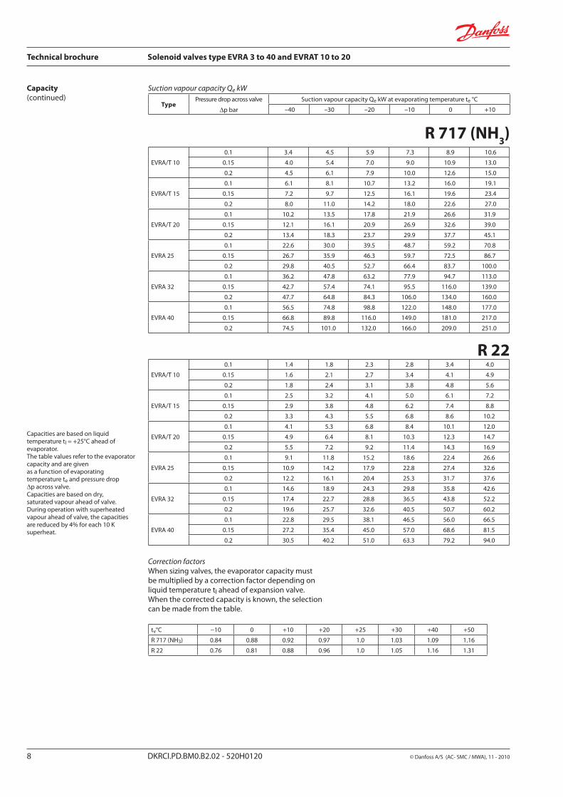
Suction vapour capacity Qe kW
Capacities are based on liquid temperature tl = +25°C ahead of evaporator.The table values refer to the evaporator capacity and are given as a function of evaporating temperature te and pressure drop ∆p across valve.Capacities are based on dry, saturated vapour ahead of valve.During operation with superheated vapour ahead of valve, the capacities are reduced by 4% for each 10 K superheat.
Correction factorsWhen sizing valves, the evaporator capacity must be multiplied by a correction factor depending on liquid temperature tl ahead of expansion valve. When the corrected capacity is known, the selection can be made from the table.
TypePressure drop across valve
∆p bar
Suction vapour capacity Qe kW at evaporating temperature te °C
–40 –30 –20 –10 0 +10

R 134aEVRA/T 10
0.1 0.87 1.2 1.6 2.1 2.6 3.2
0.15 0.99 1.4 1.9 2.4 3.2 3.9
0.2 1.1 1.6 2.1 2.8 3.5 4.5
EVRA/T 15
0.1 1.6 2.1 2.8 3.8 4.7 5.7
0.15 1.8 2.5 3.4 4.4 5.7 7.0
0.2 2.0 2.8 3.8 5.0 6.3 8.1
EVRA/T 20
0.1 2.6 3.6 4.7 6.3 7.8 9.5
0.15 3.0 4.2 5.6 7.3 9.5 11.7
0.2 3.3 4.7 6.4 8.3 10.5 13.5
EVRA 25
0.1 5.8 7.9 10.5 13.9 17.2 21.1
0.15 6.6 9.3 12.5 16.3 21.1 25.9
0.2 7.3 10.4 14.1 18.5 23.4 29.9
EVRA 32
0.1 9.3 12.6 16.8 22.2 27.7 33.8
0.15 10.6 14.9 20.0 26.1 33.8 41.4
0.2 11.7 16.6 22.6 29.6 37.4 47.8
EVRA 40
0.1 14.5 19.8 26.3 34.8 43.3 52.8
0.15 16.5 23.3 31.3 40.8 52.8 64.8
0.2 18.3 26.0 35.3 46.3 58.5 74.8
R 404A
EVRA/T 10
0.1 1.2 1.5 2.0 2.5 3.1 3.7
0.15 1.4 1.8 2.4 3.1 3.8 4.6
0.2 1.6 2.1 2.7 3.4 4.3 5.3
EVRA/T 15
0.1 2.1 2.7 3.6 4.5 5.5 6.6
0.15 2.5 3.3 4.3 5.5 6.8 8.2
0.2 2.8 3.7 4.9 6.1 7.8 9.5
EVRA/T 20
0.1 3.5 4.6 6.0 7.5 9.2 11.1
0.15 4.1 5.5 7.1 9.2 11.3 13.6
0.2 4.6 6.2 8.1 10.2 13.0 15.8
EVRA 25
0.1 7.7 10.1 13.3 16.6 20.4 24.6
0.15 9.1 12.1 15.8 20.4 25.0 30.3
0.2 10.3 13.8 18.0 22.7 28.8 35.0
EVRA 32
0.1 12.3 16.2 21.3 26.6 32.6 39.4
0.15 14.6 19.4 25.3 32.6 40.0 48.5
0.2 16.5 22.0 28.8 36.3 46.1 56.0
EVRA 40
0.1 19.3 25.3 33.3 41.5 51.0 61.5
0.15 22.9 30.3 39.5 51.0 62.5 75.6
0.2 25.8 34.5 45.0 56.8 72.1 87.5
tv°C −10 0 +10 +20 +25 +30 +40 +50
R 134a 0.76 0.81 0.88 0.96 1.0 1.05 1.16 1.31
R 404A 0.70 0.76 0.84 0.94 1.0 1.07 1.24 1.47
Technical brochure Solenoid valves, type EVRA 3 to 40 and EVRAT 10 to 20
© Danfoss A/S (AC-SMC /MWA), 11 - 2010 DKRCI.PD.BM0.B2.02 - 520H0120 9
Capacity(continued)
Suction vapour capacity Qe kW
Capacities are based on liquid temperature tl = +25°C ahead of evaporator.The table values refer to the evaporator capacity and are given as a function of evaporating temperature te and pressure drop ∆p across valve.Capacities are based on dry, saturated vapour ahead of valve.During operation with superheated vapour ahead of valve, the capacities are reduced by 4% for each 10 K superheat.
Correction factorsWhen sizing valves, the evaporator capacity must be multiplied by a correction factor depending on liquid temperature tl ahead of expansion valve. When the corrected capacity is known, the selection can be made from the table.
TypePressure drop across valve
∆p bar
Suction vapour capacity Qe kW at evaporating temperature te °C
–40 –30 –20 –10 0 +10

EVRA 3
0.1 1.8 2.1 2.3 2.5 2.6
0.2 2.6 2.9 3.2 3.5 3.7
0.4 3.8 4.2 4.6 4.9 5.3
0.8 5.1 6.0 6.5 7.1 7.6
1.6 7.4 8.3 9.1 9.9 10.9
EVRA/T 10
0.1 12.0 13.4 14.7 16.0 17.2
0.2 17.1 19.0 20.9 22.7 24.4
0.4 24.5 27.1 29.7 32.2 34.7
0.8 34.0 39.0 42.6 46.1 49.5
1.6 48.5 53.8 59.1 64.3 71.3
EVRA/T 15
0.1 21.7 24.1 26.4 28.8 31.0
0.2 30.8 34.2 37.5 40.8 44.0
0.4 44.1 48.8 53.5 58.0 62.4
0.8 61.2 70.3 76.7 83.0 89.1
1.6 87.4 96.9 106.0 116.0 128.0
EVRA/T 20
0.1 36.1 40.1 44.0 48.0 51.7
0.2 51.4 57.0 62.6 68.0 73.2
0.4 73.5 81.3 89.1 96.7 104.0
0.8 102.0 117.0 128.0 138.0 148.0
1.6 146.0 161.0 177.0 193.0 214.0
EVRA 25
0.1 80.2 89.1 98.0 107.0 115.0
0.2 114.0 127.0 139.0 151.0 163.0
0.4 163.0 181.0 198.0 215.0 231.0
0.8 227.0 260.0 284.0 307.0 330.0
1.6 324.0 358.0 394.0 429.0 475.0
EVRA 32
0.1 128.0 143.0 157.0 171.0 184.0
0.2 183.0 203.0 223.0 242.0 260.0
0.4 261.0 289.0 317.0 344.0 370.0
0.8 362.0 416.0 455.0 492.0 528.0
1.6 518.0 574.0 631.0 688.0 761.0
EVRA 40
0.1 201.0 223.0 244.0 267.0 287.0
0.2 286.0 317.0 348.0 378.0 407.0
0.4 408.0 452.0 495.0 537.0 578.0
0.8 566.0 650.0 710.0 769.0 825.0
1.6 809.0 897.0 986.0 1074.0 1188.0
R 717 (NH3)
to °C −40 −30 −20 −10 0 +10
R 717 (NH3) 0.89 0.91 0.96 1.0 1.06 1.10
Technical brochure Solenoid valves type EVRA 3 to 40 and EVRAT 10 to 20
10 DKRCI.PD.BM0.B2.02 - 520H0120 © Danfoss A/S (AC- SMC / MWA), 11 - 2010
Capacity(continued) Hot gas capacity Qh kW
Type Pressure drop across valve
∆p bar
Hot gas capacity Qe kW
Evaporating temp.te =−10°C. Hot gas temp. th = tc + 25°C.Subcooling ∆tsub=4K
Condensing temperature tc °C
+20 +30 +40 +50 +60
An increase in hot gas temperature th of 10 K, based on th = tc +25°C, reduces valve capacity approx. 2% and vice versa.
A change in evaporating temperature te changes valve capacity; see correction factor table below.
Correction factorWhen sizing valves, the table value must be multiplied by a correction factor depending on evaporating temperature te.

R 22
EVRA 3
0.1 0.68 0.72 0.76 0.78 0.79
0.2 0.97 1.0 1.1 1.1 1.1
0.4 1.4 1.5 1.5 1.6 1.6
0.8 1.9 2.0 2.1 2.3 2.3
1.6 2.7 2.9 3.0 3.1 3.2
EVRA/T 10
0.1 4.4 4.7 4.9 5.1 5.2
0.2 6.3 6.7 7.0 7.2 7.3
0.4 9.0 9.6 10.0 10.3 10.4
0.8 12.4 13.2 13.9 14.7 14.9
1.6 17.5 18.6 19.6 20.2 20.5
EVRA/T 15
0.1 8.0 8.5 8.9 9.2 9.3
0.2 11.4 12.1 12.6 13.0 13.2
0.4 16.3 17.2 18.0 18.5 18.7
0.8 22.3 23.1 24.9 26.5 26.8
1.6 31.5 33.5 35.2 36.4 36.9
EVRA/T 20
0.1 13.3 14.1 14.8 15.3 15.5
0.2 19.0 20.1 21.0 21.7 22.0
0.4 27.1 28.7 30.0 30.9 31.2
0.8 37.1 38.4 41.5 44.2 44.6
1.6 52.5 55.9 58.6 60.6 61.5
EVRA 25
0.1 29.6 31.4 32.9 34.0 34.4
0.2 42.1 44.6 46.7 48.2 48.8
0.4 60.2 63.8 66.6 68.6 69.4
0.8 82.5 87.9 92.3 98.2 99.2
1.6 117.0 124.0 130.0 135.0 137.0
EVRA 32
0.1 47.4 50.2 52.6 54.4 55.0
0.2 67.4 71.4 74.7 77.1 78.1
0.4 96.3 102.0 107.0 110.0 111.0
0.8 132.0 140.0 148.0 157.0 159.0
1.6 187.0 199.0 209.0 216.0 219.0
EVRA 40
0.1 74.0 78.5 82.3 85.0 86.0
0.2 105.0 112.0 117.0 121.0 122.0
0.4 151.0 159.0 167.0 172.0 174.0
0.8 206.0 222.0 231.0 246.0 248.0
1.6 291.0 310.0 326.0 337.0 342.0
to °C −40 −30 −20 −10 0 +10
R 22 0.90 0.94 0.97 1.0 1.03 1.05
Technical brochure Solenoid valves, type EVRA 3 to 40 and EVRAT 10 to 20
© Danfoss A/S (AC-SMC /MWA), 11 - 2010 DKRCI.PD.BM0.B2.02 - 520H0120 11
Capacity(continued)
Type Pressure drop across valve
∆p bar
Hot gas capacity Qe kW
Evaporating temp.te =−10°C. Hot gas temp. th = tc + 25°C.Subcooling ∆tsub=4K
Condensing temperature tc °C
+20 +30 +40 +50 +60
An increase in hot gas temperature th of 10 K, based on th = tc +25°C, reduces valve capacity approx. 2% and vice versa.
A change in evaporating temperature te changes valve capacity; see correction factor table below.
Correction factorWhen sizing valves, the table value must be multiplied by a correction factor depending on evaporating temperature te.
Hot gas capacity Qh kW

R 134a
EVRA 3
0.1 0.54 0.57 0.6 0.61 0.6
0.2 0.77 0.82 0.85 0.86 0.85
0.4 1.1 1.2 1.2 1.2 1.2
0.8 1.5 1.6 1.7 1.8 1.8
1.6 2.2 2.3 2.4 2.5 2.4
EVRA/T 10
0.1 3.5 3.7 3.9 4.0 3.9
0.2 5.0 5.3 5.5 5.6 5.6
0.4 7.0 7.7 7.9 8.0 7.9
0.8 9.9 10.5 11.0 11.6 11.4
1.6 14.3 15.1 15.7 16.0 15.9
EVRA/T 15
0.1 6.4 6.7 7.0 7.1 7.1
0.2 9.1 9.6 10.0 10.1 10.0
0.4 12.6 13.8 14.2 14.4 14.3
0.8 17.9 19.0 19.8 20.8 20.5
1.6 25.7 27.2 28.2 28.8 28.6
EVRA/T 20
0.1 10.6 11.2 11.7 11.8 11.8
0.2 15.1 16.0 16.6 16.8 16.7
0.4 21.0 22.9 23.7 24.0 23.8
0.8 29.8 31.6 33.0 34.7 34.2
1.6 42.8 45.3 47.1 47.9 47.6
EVRA 25
0.1 23.6 24.9 25.9 26.4 26.2
0.2 33.6 35.5 36.8 37.4 37.1
0.4 46.6 51.0 52.7 53.4 52.9
0.8 66.2 70.2 73.2 77.0 76.0
1.6 95.2 101.0 105.0 107.0 106.0
EVRA 32
0.1 37.6 39.8 41.4 42.1 41.8
0.2 53.8 56.8 58.9 59.8 59.4
0.4 74.7 81.6 84.3 85.4 84.6
0.8 106.0 112.0 117.0 123.0 122.0
1.6 152.0 161.0 167.0 170.0 169.0
EVRA 40
0.1 58.8 62.3 64.7 65.8 65.3
0.2 84.1 88.8 92.1 93.5 92.8
0.4 117.0 127.0 132.0 134.0 132.0
0.8 166.0 176.0 183.0 192.0 190.0
1.6 238.0 252.0 262.0 266.0 265.0
to °C −40 −30 −20 −10 0 +10
R 134a 0.88 0.92 0.98 1.0 1.04 1.08
Technical brochure Solenoid valves type EVRA 3 to 40 and EVRAT 10 to 20
12 DKRCI.PD.BM0.B2.02 - 520H0120 © Danfoss A/S (AC- SMC / MWA), 11 - 2010
Type Pressure drop across valve
∆p bar
Hot gas capacity Qe kW
Evaporating temp.te =−10°C. Hot gas temp. th = tc + 25°C.Subcooling ∆tsub=4K
Condensing temperature tc °C
+20 +30 +40 +50 +60
Capacity(continued) Hot gas capacity Qh kW
An increase in hot gas temperature th of 10 K, based on th = tc +25°C, reduces valve capacity approx. 2% and vice versa.
A change in evaporating temperature te changes valve capacity; see correction factor table below.
Correction factorWhen sizing valves, the table value must be multiplied by a correction factor depending on evaporating temperature te.

EVRA 3
0.1 0.62 0.63 0.62 0.59 0.54
0.2 0.87 0.89 0.88 0.83 0.76
0.4 1.2 1.3 1.3 1.2 1.1
0.8 1.7 1.7 1.7 1.7 1.5
1.6 2.4 2.5 2.4 2.3 2.1
EVRA/T 10
0.1 4.0 4.1 4.0 3.8 3.5
0.2 5.7 5.8 5.7 5.5 5.0
0.4 8.1 8.2 8.2 7.8 7.0
0.8 11.1 11.4 11.3 11.1 10.1
1.6 15.7 16.0 15.8 15.2 13.9
EVRA/T 15
0.1 7.3 7.4 7.3 6.9 6.3
0.2 10.2 10.4 10.3 9.8 8.9
0.4 14.6 14.8 14.7 14.0 12.7
0.8 20.1 20.4 20.3 20.0 18.1
1.6 28.3 28.8 28.4 27.4 25.0
EVRA/T 20
0.1 12.1 12.3 12.1 11.5 10.5
0.2 17.1 17.3 17.2 16.3 14.9
0.4 24.4 24.7 24.5 23.3 21.1
0.8 33.4 34.0 33.9 33.3 30.2
1.6 47.1 48.0 47.4 45.6 41.6
EVRA 25
0.1 26.8 27.4 26.9 25.6 23.3
0.2 37.9 38.4 38.2 36.3 33.0
0.4 54.2 54.9 54.5 51.7 47.0
0.8 74.2 75.6 75.3 74.0 67.2
1.6 105.0 107.0 105.0 101.0 92.5
EVRA 32
0.1 43.0 43.8 43.0 40.9 37.3
0.2 60.6 61.4 61.1 58.1 52.8
0.4 86.7 87.8 87.2 82.7 75.2
0.8 119.0 121.0 120.0 118.0 107.0
1.6 167.0 171.0 168.0 162.0 148.0
EVRA 40
0.1 67.0 68.5 67.3 64.0 58.3
0.2 94.8 96.0 95.5 90.8 82.5
0.4 136.0 137.0 136.0 129.0 117.0
0.8 186.0 189.0 188.0 185.0 168.0
1.6 262.0 266.0 263.0 253.0 231.0
to °C −40 −30 −20 −10 0 +10
R 404A 0.86 0.88 0.93 1.0 1.03 1.07
R 404A
Technical brochure Solenoid valves, type EVRA 3 to 40 and EVRAT 10 to 20
© Danfoss A/S (AC-SMC /MWA), 11 - 2010 DKRCI.PD.BM0.B2.02 - 520H0120 13
Type Pressure drop across valve
∆p bar
Hot gas capacity Qe kW
Evaporating temp.te =−10°C. Hot gas temp. th = tc + 25°C.Subcooling ∆tsub=4K
Condensing temperature tc °C
+20 +30 +40 +50 +60
An increase in hot gas temperature th of 10 K, based on th = tc +25°C, reduces valve capacity approx. 2% and vice versa.
A change in evaporating temperature te changes valve capacity; see correction factor table below.
Correction factorWhen sizing valves, the table value must be multiplied by a correction factor depending on evaporating temperature te.
Capacity(continued) Hot gas capacity Qh kW

EVRA 3
+90
+25 0.003 0.005 0.006 0.007 0.007 0.007 0.007 0.007 0.007
+35 0.004 0.005 0.007 0.009 0.009 0.01 0.01 0.01 0.01
+45 0.005 0.006 0.009 0.01 0.011 0.012 0.013 0.013 0.013
EVRA/T 10
+25 0.022 0.03 0.04 0.045 0.048 0.048 0.048 0.048 0.048
+35 0.026 0.036 0.048 0.056 0.061 0.064 0.065 0.065 0.065
+45 0.030 0.041 0.056 0.066 0.074 0.079 0.083 0.085 0.086
EVRA/T 15
+25 0.040 0.054 0.072 0.081 0.086 0.087 0.087 0.087 0.087
+35 0.046 0.064 0.086 0.1 0.109 0.115 0.117 0.117 0.117
+45 0.053 0.074 0.101 0.12 0.133 0.142 0.149 0.153 0.155
EVRA/T 20
+25 0.066 0.09 0.12 0.12 0.144 0.145 0.145 0.145 0.145
+35 0.077 0.107 0.144 0.167 0.182 0.191 0.195 0.195 0.195
+45 0.089 0.124 0.169 0.199 0.211 0.237 0.248 0.255 0.258
EVRA 25
+25 0.143 0.197 0.26 0.296 0.313 0.316 0.316 0.316 0.316
+35 0.168 0.232 0.313 0.364 0.397 0.417 0.425 0.425 0.425
+45 0.194 0.269 0.368 0.434 0.482 0.516 1.54 0.555 0.561
EVRA 32
+25 0.233 0.322 0.424 0.483 0.511 0.516
+35 0.274 0.379 0.511 0.594 0.648 0.681 0.694
+45 0.316 0.439 0.601 0.709 0.787 0.842 0.882 0.906 0.916
EVRA 40
+25 0.362 0.503 0.663 0.755 0.798 0.806
+35 0.429 0.592 0.798 0.929 1.013 1.064 1.084
+45 0.495 0.686 0.939 1.107 1.23 1.316 1.378 1.416 1.431
R 717 (NH3)
R 22EVRA 3
+90
+25 0.008 0.011 0.014 0.016 0.017 0.017 0.017 0.017 0.017
+35 0.009 0.012 0.017 0.019 0.021 0.022 0.022 0.022 0.022
+45 0.010 0.014 0.019 0.022 0.025 0.026 0.027 0.028 0.028
EVRA/T 10
+25 0.051 0.069 0.092 0.104 0.109 0.111 0.111 0.111 0.111
+35 0.058 0.08 0.108 0.125 0.136 0.142 0.144 0.144 0.144
+45 0.066 0.092 0.125 0.146 0.162 0.172 0.179 0.183 0.183
EVRA/T 15
+25 0.091 0.125 0.165 0.187 0.197 0.199 0.199 0.199 0.199
+35 0.105 0.144 0.194 0.225 0.244 0.256 0.258 0.258 0.258
+45 0.119 0.165 0.224 0.263 0.291 0.31 0.322 0.329 0.330
EVRA/T 20
+25 0.152 0.208 0.275 0.311 0.328 0.332 0.332 0.332 0.332
+35 0.174 0.241 0.323 0.375 0.407 0.425 0.431 0.431 0.431
+45 0.193 0.275 0.374 0.439 0.485 0.516 0.537 0.548 0.55
EVRA 25
+25 0.331 0.453 0.599 0.677 0.715 0.722 0.722 0.722 0.722
+35 0.38 0.524 0.704 0.816 0.886 0.925 0.938 0.938 0.938
+45 0.431 0.598 0.814 0.956 1.056 1.125 1.169 1.192 1.197
EVRA 32
+25 0.539 0.739 0.976 1.106 1.168 1.179
+35 0.619 0.856 1.15 1.331 1.446 1.509 1.531
+45 0.704 0.978 1.329 1.562 1.723 1.837 1.909 1.947 1.955
EVRA 40
+25 0.843 1.155 1.525 1.728 1.825 1.843
+35 0.968 1.338 1.798 2.08 2.26 2.358 2.393
+45 1.1 1.528 2.078 2.44 2.693 2.87 2.383 3.043 3.055
Technical brochure Solenoid valves type EVRA 3 to 40 and EVRAT 10 to 20
14 DKRCI.PD.BM0.B2.02 - 520H0120 © Danfoss A/S (AC- SMC / MWA), 11 - 2010
Capacity(continued)
Hot gas capacity Gh kg/s
An increase in hot gas temperature th of 10 K reduces valve capacity approx. 2% and vice versa.
TypeHot gas
temperature t
h°C
Condensing temperature
tk°C
Hot gas capacity Gh kg/s at pressure drop across valve ∆p bar
0.5 1 2 3 4 5 6 7 8

EVRA 3
+60
+25 0.007 0.009 0.011 0.012 0.012
+35 0.009 0.011 0.014 0.016 0.016 0.016 0.016
+45 0.01 0.012 0.018 0.02 0.021 0.021 0.021 0.021 0.021
EVRA/T 10
+25 0.048 0.06 0.074 0.077 0.077
+35 0.055 0.071 0.092 0.103 0.104 0.104
+45 0.06 0.084 0.111 0.127 0.134 0.135 0.135 0.135 0.135
EVRA/T 15
+25 0.081 0.108 0.134 0.14 0.14
+35 0.094 0.129 0.166 0.192 0.187 0.187 0.187
+45 0.108 0.151 0.2 0.228 0.241 0.244 0.244 0.244 0.244
EVRA/T 20
+25 0.134 0.18 0.223 0.233 0.233
+35 0.157 0.215 0.276 0.307 0.312 0.312 0.312
+45 0.181 0.252 0.333 0.381 0.403 0.407 0.407 0.407 0.407
EVRA 25
+25 0.292 0.391 0.486 0.506 0.506
+35 0.341 0.467 0.602 0.668 0.679 0.679 0.679
+45 0.393 0.549 0.725 0.83 0.876 0.885 0.885 0.885 0.885
EVRA 32
+25 0.478 0.638 0.793 1.826 0.826
+35 0.556 0.763 0.994 1.091 1.108 1.108 1.108
+45 0.641 0.897 1.197 1.354 1.432 1.446 1.446 1.446 1.446
EVRA 40
+25 0.747 0.998 1.24 1.291 1.291
+35 0.87 1.192 1.553 1.704 1.731 1.731 1.731
+45 1.002 1.402 1.87 2.117 2.237 2.259 2.259 2.259
EVRA 3
+60
+25 0.01 0.013 0.018 0.021 0.022 0.023 0.023 0.023 0.023
+35 0.011 0.015 0.02 0.024 0.027 0.028 0.029 0.029 0.03
+45 0.012 0.017 0.023 0.028 0.032 0.034 0.035 0.036 0.037
EVRA/T 10
+25 0.063 0.087 0.116 0.134 0.145 0.148 0.149 0.149 0.149
+35 0.072 0.1 0.134 0.158 0.174 0.184 0.19 0.19 0.192
+45 0.081 0.112 0.153 0.182 0.203 0.228 0.228 0.237 0.239
EVRA/T 15
+25 0.113 0.157 0.21 0.242 0.26 0.267 0.269 0.269 0.269
+35 0.129 0.18 0.242 0.285 0.313 0.332 0.341 0.342 0.346
+45 0.146 0.202 0.275 0.327 0.365 0.393 0.411 0.424 0.431
EVRA/T 20
+25 0.189 0.262 0.35 0.403 0.433 0.445 0.449 0.449 0.449
+35 0.215 0.3 0.404 0.474 0.521 0.552 0.569 0.57 0.576
+45 0.243 0.337 0.459 0.545 0.609 0.656 0.684 0.707 0.719
EVRA 25
+25 0.411 0.57 0.763 0.878 0.942 0.969 0.978 0.978 0.978
+35 0.468 0.653 0.881 1.032 1.136 1.203 1.239 1.241 1.253
+45 0.529 0.734 1.0 1.188 1.326 1.43 1.49 1.539 1.566
EVRA 32
+25 0.672 0.931 1.245 1.432 1.539 1.581 1.581 1.581 1.581
+35 0.765 1.069 1.436 1.686 1.854 1.964 2.022 2.025 2.025
+45 0.862 1.198 1.632 1.939 1.836 2.34 2.433 2.513 2.557
EVRA 40
+25 1.05 1.454 1.946 2.238 2.406 2.471 2.471 2.471 2.471
+35 1.195 1.657 2.245 2.635 2.897 3.068 3.161 3.166 3.166
+45 1.348 1.873 2.55 3.03 3.384 3.65 3.801 3.926 3.995
R 134a
R 404A
Technical brochure Solenoid valves, type EVRA 3 to 40 and EVRAT 10 to 20
© Danfoss A/S (AC-SMC /MWA), 11 - 2010 DKRCI.PD.BM0.B2.02 - 520H0120 15
TypeVarmgas-
temperatur t
h°C
Kondense- ringstemp.
tk°C
Varmgaskapacitet Gh kg/s ved trykfaldet i ventilen ∆p bar
0.5 1 2 3 4 5 6 7 8
Capacity(continued)
Hot gas capacity Gh kg/s
An increase in hot gas temperature th of 10 K reduces valve capacity approx. 2% and vice versa.

EVRA 3
EVRA 25
Technical brochure Solenoid valves type EVRA 3 to 40 and EVRAT 10 to 20
16 DKRCI.PD.BM0.B2.02 - 520H0120 © Danfoss A/S (AC- SMC / MWA), 11 - 2010
4. Coil16. Armature18. Valve plate / Pilot valve plate20. Earth terminal24. Connection for flexible steel hose28. Gasket29. Pilot orifice30. O-ring31. Piston ring36. DIN plug40. Terminal box43. Valve cover44. O-ring45. Valve cover gasket48. Flange gasket49. Valve body51. Cover / Threaded plug53. Manual operation spindle59. Strainer73. Equalization hole74. Main channel75. Pilot channel76. Compression spring80. Diaphragm/Servo piston82. Support washer83. Valve seat84. Main valve plate
DesignFunction
EVRA solenoid valves are designed on two different principles:1. Direct operation2. Servo operation
1. Direct operationEVRA 3 is direct operated. The valve opens direct for full flow when the armature (16) moves up into the magnetic field of the coil. This means that the valve operates with a min. differential pressure of 0 bar.The teflon valve plate (18) is fitted direct on the armature (16). Inlet pressure acts from above on the armature and the valve plate. Thus, inlet pressure, spring force and the weight of the armature act to close the valve when the coil is currentless.
2. Servo operationEVRA/T 10 → 20 are servo operated with a “floating” diaphragm (80). The pilot orifice (29) of stainless steel is placed in the centre of the diaphragm. The teflon pilot valve plate (18) is fitted direct to the armature (16).When the coil is currentless, the main orifice and pilot orifice are closed. The pilot orifice and main orifice are held closed by the weight of the armature, the armature spring force and the differential pressure between inlet and outlet sides.
When current is applied to the coil the armature is drawn up into the magnetic field and opens the pilot orifice. This relieves the pressure above the diaphragm, i.e. the space above the diaphragm becomes connected to the outlet side of the valve. The differential pressure between inlet and outlet sides then presses the diaphragm away from the main orifice and opens it for full flow. Therefore a certain minimum differential pressure is necessary to open the EVRA valve and keep it open. For diffential pressure 0 bar use EVRAT valves.For EVRA 10 → 20 valves this differential pressure is 0.05 bar.When current is switched off, the pilot orifice closes. Via the equalization holes (73) in the diaphragm, the pressure above the diaphragm then rises to the same value as the inlet pressure and the diaphragm closes the main orifice.
EVRA 25, 32 and 40 are servo operated piston valves. The valves are closed with currentless coil. The servo piston (80) with main valve plate (84) closes against the valve seat (83) by means of the differential pressure between inlet and outlet side of the valve, the force of the compression spring (76) and possibly the piston weight.When current to the coil is switched on, the pilot orifice (29) opens. This relieves the pressure on the piston spring side of the valve. The differential pressure will then open the valve.The minimum differential pressure needed for full opening of the valves is 0.2 bar.
EVRA/T 10, 15 and 20
EVRA 32 and 40

EVRA 3 EVRA/T 10/15/20
EVRA 25 EVRA 32/40
Technical brochure Solenoid valves, type EVRA 3 to 40 and EVRAT 10 to 20
© Danfoss A/S (AC-SMC /MWA), 11 - 2010 DKRCI.PD.BM0.B2.02 - 520H0120 17
Material specification
No. Description Solenoid valves Material Analysis Mat.no. W.no. ISO EN
1 Valve bodyEVRA 3 Free-cutting steel 11MnPb30 10277-3
EVRA/T 10/15/20 Cast-iron GJS-400-18-LT 1563
3 Armature tube EVRA 3/10/15/20 Stainless steel X2CrNi19-11 10088
4 Flange EVRA/T 3/10/15/20 Steel S235JRG2 10025
5 GasketEVRA 3 Aluminium Al 99.5 10210
EVRA/T 10/15/20 Rubber Cr
6 Gasket EVRA/T 3/10/15/20 asbestos-free
7 Armature tube nut EVRA/T 3/10/15/20 Stainless steel X8CrNiS18-9 10088
8 Cover EVRA/T 10/15/20 Cast-iron GJS-400-18-LT 1563
9 Cover/ thread plug EVRA/T 10/15/20 Free-cutting steel 11SMnPb30 10277-3
10 Gasket EVRA/T 10/15/20 Aluminium Al 99.5 10210
11 Bolts EVRA/T 10/15/20 Stainless steel A2-70 3506
12 Valve seat EVRA/T 10/15/20 Teflon (PTFE)
No. Description Solenoid valves Material Analysis Mat.no. W.no. ISO EN
1 Valve body EVRA 25/32/40 Cast-iron GJS-400-18-LT 1563
2 Armature tube nut EVRA 25/32/40 Stainless steel X8CrNiS 18-9 10088
3 Armature tube EVRA 25/32/40 Stainless steel X2CrNi19-11 10088
4 FlangeEVRA 25 Steel S235JRG2 10025
EVRA 32/40 Steel P285QH 10222-4
5 Gasket EVRA 25/32/40 Aluminium Al 99.5 10210
6 GasketEVRA 25 asbestos-free
EVRA 32/40 Rubber Cr
7 Cover/thread plugEVRA 25 Free-cutting steel 11SMnPb30 10277-3
EVRA 32/40 Stainless steel X5CrNi17-10 10088
8 Gasket EVRA 25 Rubber CR
9 Bolts EVRA 25 Stainless steel A2-70 3506
10 Cover EVRA 25 Cast-iron GJS-400-18-LT 1563
11 Bolts EVRA 25/32/40 Stainless steel A2-70 3506
12 Valve seat EVRA 25 Teflon (PTFE)

EVRA 3 84 19 124 65
75 85
80 68 1.2
EVRA/T 10 22 100 81 130 68 80 68 1.7
EVRA/T 15 100 81 130 68 80 68 1.8
EVRA/T 20 110 77 155 85 96 68 2.7
Technical brochure Solenoid valves type EVRA 3 to 40 and EVRAT 10 to 20
18 DKRCI.PD.BM0.B2.02 - 520H0120 © Danfoss A/S (AC- SMC / MWA), 11 - 2010
Dimensions and weight
EVRA 3 → 20Coil with terminal box
EVRA 3Coil with cable
EVRA 3 → 20Coil with DIN plugs
EVRA/T 10 → 20Coil with terminal box
EVRA 10Coil with terminal box
Weight of coil10 W: approx. 0.3 kg
12 and 20 W: approx. 0.5 kg
Weight of flange setFor EVRA 3, 10 and 15: 0.6 kg
For EVRA 20: 0.9 kg
TypeH
1H
2H
3H
4L L
1
L5 max.
BB
1
max.Weight
1)10 W 12 W 20 W
mm mm mm mm mm mm mm mm mm mm kg
1) With coil, without flanges

EVRA 25 46 141 78 162 92
75 85
95 68 3.0
EVRA 32 47 115 53 175 80 68 4.0
EVRA 40 47 115 53 175 80 68 4.0
Technical brochure Solenoid valves, type EVRA 3 to 40 and EVRAT 10 to 20
© Danfoss A/S (AC-SMC /MWA), 11 - 2010 DKRCI.PD.BM0.B2.02 - 520H0120 19
EVRA 25, 32 and 40Coil with cable
EVRA 25, 32 and 40Coil with DIN plugs
EVRA 25Coil with terminal box
EVRA 25Coil with terminal box
EVRA 32 and 40Coil with terminal box
EVRA 32 and 40Coil with terminal box
Weigh of coil10 W: approx. 0.3 kg
12 and 20 W: approx. 0.5 kg
Weight of flange setFor EVRA 25: 0.9 kg
TypeH
1H
2H
3H
4L L
1
L5 max.
BB
1
max.Weight
1)10 W 12 W 20 W
mm mm mm mm mm mm mm mm mm mm kg
1) With coil, without flanges
Dimensions and weight (continued)

Technical brochure Solenoid valves type EVRA 3 to 40 and EVRAT 10 to 20
20 DKRCI.PD.BM0.B2.02 - 520H0120 © Danfoss A/S (AC- SMC / MWA), 11 - 2010


![Data sheet Solenoid valves EVRA and EVRATfiles.danfoss.com/technicalinfo/dila/01/AI221486430911en-000809... · 12W AC [bar] Max OPD 20W DC [bar] Required coil type** Singlepack/ Multipack](https://img.dokumen.tips/doc/110x75/5bca198c09d3f2ca148bce7a/data-sheet-solenoid-valves-evra-and-12w-ac-bar-max-opd-20w-dc-bar-required.jpg)