Embed Size (px)
Citation preview
A PROJECT REPORT ON
SOLENOID OPERATED PNEUMATIC GRINDING MACHINE
Submitted in partial fulfillment of the requirement
For the award of the degree of
Bachelor of Technology
In
Mechanical Engineering
BHUPENDRA SINGH 1322040030
YASHPAL SINGH 1322040122
BAMBAM KUMAR 1322040029
BALRAM JHA 1322040028
AJIT KUMAR 1322040008
Mr. R.K.MOHANTY Prof. P.S. SANDHU
(Project Guide) (H.O.D-ME)
GHAZIABAD
Affiliated to
Dr. A.P. J Abdul Kalam Technical University, Lucknow
2016-17

Department of Mechanical Engineering Page i
CANDIDATE’S DECLARATION
We, Yashpal Singh, Bhupendra Singh, Bambam Kumar, Ajit Kumar Yadav, Balram Jha hereby
declare that the work which is being presented in the project entitled Solenoid Operated
Pneumatic Grinding Machine in partially fulfillment of the requirement for the award of the
degree “bachelor of technology in mechanical engineering” , submitted to the Dr. A.P.J. Abdul
Kalam technical university Lucknow , is an authentic record of our work carried outs under the
guidance of our guide R.K.MOHANTY.
The work reported in this dissertation has not being submitted by us for award of any other
degree .
YASHPAL SINGH (1322040122)
BHUPENDRA SINGH (1322040030)
BAMBAM KUMAR (1322040029)
AJIT KUMAR YADAV (1322040008)
BALRAM JHA (1322040028)
DATE:
PLACE: GHAZIABAD

Department of Mechanical Engineering Page ii
ACKNOWLEDGEMENT
With a deep sense of gratitude, we wish to express our sincere thanks to our supervisor,
R.K.MOHANTY for his immense help in planning and executing the work in time. The
confidence dynamism with which he guided the work requires no elaboration. His company and
assurance at the time of crisis would we remember lifelong. His valuable suggestions as final
words during the course of work are greatly acknowledge. What we know today about the
process of project, we learn from R.K.MOHANTY.
Our sincere thanks to R.K.MOHANTY for providing us constant encouragement. Our special
thanks to Dr. Vihang Garg , Dr. Dhiraj Gupta and Prof. P.S. SANDHU for extending timing
help in caring out our important pieces of work the cooperation we received from other faculty
members of our department is gratefully acknowledged. We will failing in our duty if we do not
mentions the laboratory stop and administrative stop of this department for there timely help.
Finally, we would like thank all whose direct and indirect support helped us in completing our
project in time.
Group Members
YASHPAL SINGH
BHUPENDRA SINGH
BAMBAM KUMAR
AJIT KUMAR YADAV
BALRAM JHA

Department of Mechanical Engineering Page iii
CERTIFICATE
This is certified that the project report entitled “SOLENOID OPERATED PNEUMATIC
GRINDING MACHINE” submitted by YASHPAL SINGH, BHUPENDRA SINGH, BAMBAM
KUMAR, AJIT KUMAR, BALRAM JHA is a bona-fide record of the work carried out by them
at H.I.E.T , Ghaziabad under my supervision. The matter embodied in the project work has not
been submitted earlier for the award of my degree to the best of my knowledge and belief.
Date :
R.K.MOHANTY Prof. P.S.Sandhu
Assistant Professor, ME Department H.O.D, ME
Department

Department of Mechanical Engineering Page iv
ABSTRACT
Introducing pneumatic grinding arrangement used for different jobs. Grinding has been one of
the major operation in all the industries since the era of industrialization started. But to this date
it has not seen automation at affordable costs. Hydraulic grinding solved the problems of
conventional grinding but it was too costly.
The idea of the project was to have an intermediate arrangement that solves the purpose of
automation and is also economic. The proposal is to move grinder in a direction back and forth
by pressing a single button. This has been done earlier but not with the concept of pneumatics.
And as a matter of fact pneumatic approach is cheaper than the hydraulic one. Thereby achieving
automation at a low cost. In this arrangement air compressor is employed which supplies
pressurized air to actuate pneumatic cylinder. This in turn carries the grinder forward for the
grinding action. For adjusting the feed of the job we have used lead screw arrangement. Solenoid
valve reverses the direction of air movement in the cylinder in order to bring grinder back to its
rest position.
Even being a small model for illustration this arrangement pleases by achieving close tolerances.
Also there is no fatigue to the operator. This is a very smooth-acting device, and the minimal
power loss. It can be run at nearly any speed, even at high speed, and is very efficient. It is
fascinating to watch in action, grinding being done automatically.

Department of Mechanical Engineering Page v
LIST OF FIGURES
TITLE Page no.
Figure 1 Actual project picture………….……………………………………………….4
Figure 2 Actual project picture………….……………………………………………….4
Figure 3 Abrasive grains of grinding wheel……………………………………………..7
Figure 4 Centre less grinding…………...……………………………………………......9
Figure 5 Grinding wheel…………………………………………………………………11
Figure 6 Straight grinding wheel………………………………………………………...14
Figure 7 Diamond grinding wheel…………………………………………………….....15
Figure 8 Bench grinder…………………………………………………………………..21
Figure 9 Bench vice……………………………………………………………………...22
Figure 10 Heavy-duty vice……………...………………………………………………..23
Figure 11 Air compressor………………...………………………………………………25
Figure 12 Portable air compressor……….…………………………………………….....27
Figure 13 Flow regulating valve………….………………………………………………29
Figure 14 Pneumatic cylinder…………….………………………………………………34
Figure 15 Solenoid valve………………….……………………………………………...38
Figure 16 Acme screw…………………….……………………………………………...41
Figure 17 Lead screw……………………….………………………………………….....41
Department of Mechanical Engineering Page vi
LIST OF TABLES
TITLE Page no.
1. Bond description in grinding wheels….….…………………………………...13
2. Cutting fluid for different materials…….…………………………………….16
3. Specification of components…………….……………………………………44
Department of Mechanical Engineering Page vii
CONTENTS
Candidate’s Declaration……………………………………………………………….…………i
Acknowledgement……………………………………………………………………………….ii
Certificate………………………………………………………………………………………...iii
Abstract…….…………………………………………………………………………………….iv
List of Figures……………………………………………………………………………….........v
List of Tables…………………………………………………………………………………......vi
CHAPTER-1 INTRODUCTION
1.1 – Introduction……………………………………………………………………………....1
1.2 – Innovation…………………………………………………………………………………2
1.3 – Idea arise from……………………………………………………………………………..2
CHAPTER-2 SOLENOID OPERATED PNEUMATIC GRINDING MACHINE
2.1 – Principle mechanism………………………………………………………………………5
2.2 – Assembly…………………………………………………………………………………..5
CHAPTER-3 BASIC THEORY
3.1 – Grinding (Basics)…………………………………………………………………………6
3.2 – Types of grinding…………………………………………………………………………7

Department of Mechanical Engineering Page viii
3.3 – The workpiece ……………………………………………………………………………10
3.4 – Grinding wheel……………….…………………………………………………………...11
3.5 – Lubrication ………………………....…………………………………………………….16
CHAPTER-4 COMPONENTS
4.1 – Bench grinder………………..………………………………............................................17
4.2 – Bench Vice………………………………………………………………………………..21
4.3 – Compressor …………………………………………………………………….…………24
4.4 – Flow regulating valve………….………………………………………………………….28
4.5 – Mild Steel Sheet…………………………………………………………………………..30
CHAPTER-5 CONSTRUCTION & WORKING
5.1 – Pneumatics ……………………………………………………………………………….31
5.2 – Working of pneumatic cylinder………………………………………………….……….33
5.3 – Working of solenoid valve………………………………………………………………..37
5.4 – Feed of workpiece………………………………………………………………………...40
CHAPTER-6 PROJECT ANALYSIS
6.1 Cost Analysis & Specification of Components……………………………….……………..44
6.2 Advantages…………………………………………………………………………………..44
6.3 Applications…………………………………………………………………….……………45
Department of Mechanical Engineering Page ix
6.4 Limitations…………………………………………………………………………………..45
CHAPTER-7 CONCLUSION & FUTURE SCOPE
7.1 Conclusion…………………………………………………………………………………...46
7.2 Future Scope…………………………………………………………………………………46
REFERENCES…………………………………………………………………………………47

Department of Mechanical Engineering Page 1
CHAPTER – 1
1.1 Introduction – There are many electrically operated grinding machines of different
configurations and different manufacturers are available for the use in machine shop. These
machines can grind jobs of different material precisely. Now in industry, it is necessary to grind
jobs with very high rate to achieve mass production requirements. So there is need to move for a
new technology which gives us a mass production with less time and less energy input. It is
impossible to depend upon conventional grinding machine.
By using this pneumatic grinding machine the jobs can be ground maintaining tolerances to
achieve high speed cutting rate and mass production for maximum benefit in manufacturing
industries. This machine overcomes the drawbacks and limitations of conventional grinding
machines. It can be used in a small workshops and industries as it is available in very low price
and its smaller size and high efficiency.
The setup of pneumatic grinding machine is very simple, it operates with mechanism of
pressurized air from a compressor. Compressed air pushes the piston of cylinder back and forth.
This reciprocating motion of pneumatic cylinder is used to obtain the linear motion of grinder
mounting plate and material is ground.
The size and shape of this setup is small. Base plate is provided for placing the work piece to be
ground. A simple air compressor is required for its operation. These machines are so precise that
they can grind jobs with minimum time made up of different materials. For industries to achieve
the mass production, it is necessary to jobs with high rate. So it is impossible to depend upon
conventional grinding machines and need the improvement in technology and design of such
machines.
Department of Mechanical Engineering Page 2
1.2 Innovation
When we were searching for our project in the market we saw the demand of grinder is
considerably increasing day by day with the growth of industrialization, engineering sector, real
estate, automobile sector, etc.
It is used in almost every sector for grinding of materials like angle, channel, flat plates, rods and
such other things. It is also required in auto repairing shops, general repairing workshops, fitting
shops, welding shops and technical institutes. Govt. department like Railway, Defense, PWD and
others are one of the main users of it.
In India large nos. of small enterprises are engaged in its manufacturing. By considering its
demand, new production unit has great prospect. So from that we have concluded that the future
based grinding machine is use for very costly machinery and in locomotives.
User can use this project in small industry, which cannot afford costly machinery.
1.3 Idea Arise from
In the older days industries performed the grinding process on the conventional grinding
machines and that too manually i.e. the operator had to manually grind the job and the
dimensional tolerances were completely dependent on his skills. But it was not a reliable process
as every time the human error played its role. Gradually hydraulic grinding came into the scene.
Though it brought automation with itself but it was very costly.
Thus the existing limitations of both the concepts inspired us to innovate our above stated
project. The idea was to have a concept eliminating the existing challenges and incorporate the
available benefits. The field of pneumatics serves the purpose of automation at an affordable
price.
Department of Mechanical Engineering Page 3
We started working on our project and very soon the results came into light. We were able to
grind the jobs at a better speed, with automation, at a lower cost and even tolerances were being
maintained. The size and weight ratio of our project was duly maintained and the model so
prepared was fully ready to serve in the industry.
Department of Mechanical Engineering Page 4
CHAPTER – 2
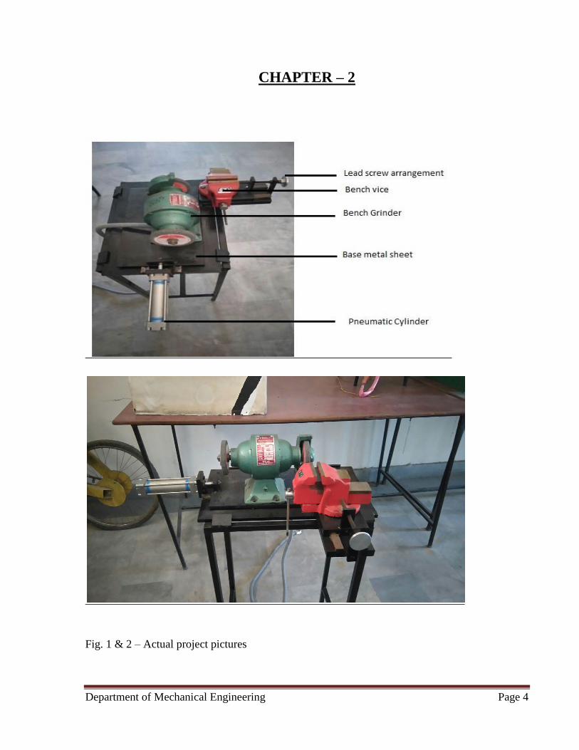
Fig. 1 & 2 – Actual project pictures

Department of Mechanical Engineering Page 5
2.1 Principle Mechanism
Solenoid operated pneumatic grinding machine works on the principle of pneumatics. In this
compressed air from the compressor pushes the grinder in the forward direction. Lead screw
arrangement has been used to give feed to the work-piece. On adjusting the feed forward stroke
of the piston of pneumatic cylinder pushes grinder forward. The solenoid valve is used for
reversal of direction and to bring the grinder backward for the next stroke.
2.2 Assembly
For assembly of solenoid operated pneumatic grinding machine first of all mount the grinder on
base plate horizontally, with pneumatic grinder on one of the ends so that it can utilize
movement of piston as its forward stroke. On the same base fix a vice for holding the job and
adjust the feed using lead screw arrangement. Connect output of compressor to the solenoid
valve using pipe of suitable diameter. Also the solenoid valve is connected to pneumatic cylinder
too.
For controlling the amount of air from compressor that enters the cylinder use flow regulating
valves. These also assure a jerk free operation, if adjusted properly. A compressor generating a
pressure of 4 kgf is sufficient for running our proposed arrangement. Also to make sure that the
grinder plate moves forward mount it on another plate with grooves engraved on it.
Finally the whole apparatus can be placed on stand to be given some height as per our
convenience.

Department of Mechanical Engineering Page 6
CHAPTER – 3
3.1 Grinding (basics) - Grinding is an abrasive machining process that uses a grinding
wheel as the cutting tool. A wide variety of machines are used for grinding:
• Hand-cranked knife-sharpening stones (grindstones)
• Handheld power tools such as angle grinders and die grinders
• Various kinds of expensive industrial machine tools called grinding machines
• Bench grinders often found in residential garages and basements
Grinding practice is a large and diverse area of manufacturing and toolmaking. It can produce
very fine finishes and very accurate dimensions; yet in mass production contexts it can also
rough out large volumes of metal quite rapidly. It is usually better suited to the machining of
very hard materials than is "regular" machining (that is, cutting larger chips with cutting tools
such as tool bits or milling cutters), and until recent decades it was the only practical way to
machine such materials as hardened steels. Compared to "regular" machining, it is usually better
suited to taking very shallow cuts, such as reducing a shaft’s diameter by half a thousandth of an
inch or 12.7 μm.
Grinding is a subset of cutting, as grinding is a true metal-cutting process. Each grain of abrasive
functions as a microscopic single-point cutting edge (although of high negative rake angle), and
shears a tiny chip that is analogous to what would conventionally be called a "cut" chip (turning,
milling, drilling, tapping, etc. However, among people who work in the machining fields, the
term cutting is often understood to refer to the macroscopic cutting operations, and grinding is
often mentally categorized as a "separate" process. This is why the terms are usually used in
separately in shop-floor practice.
Department of Mechanical Engineering Page 7
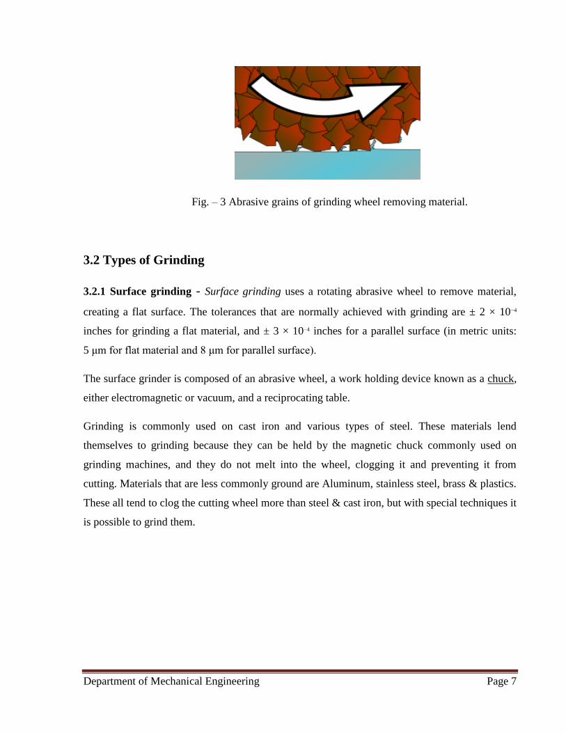
Fig. – 3 Abrasive grains of grinding wheel removing material.
3.2 Types of Grinding
3.2.1 Surface grinding - Surface grinding uses a rotating abrasive wheel to remove material,
creating a flat surface. The tolerances that are normally achieved with grinding are ± 2 × 10⁻⁴
inches for grinding a flat material, and ± 3 × 10⁻⁴ inches for a parallel surface (in metric units:
5 μm for flat material and 8 μm for parallel surface).
The surface grinder is composed of an abrasive wheel, a work holding device known as a chuck,
either electromagnetic or vacuum, and a reciprocating table.
Grinding is commonly used on cast iron and various types of steel. These materials lend
themselves to grinding because they can be held by the magnetic chuck commonly used on
grinding machines, and they do not melt into the wheel, clogging it and preventing it from
cutting. Materials that are less commonly ground are Aluminum, stainless steel, brass & plastics.
These all tend to clog the cutting wheel more than steel & cast iron, but with special techniques it
is possible to grind them.

Department of Mechanical Engineering Page 8
3.2.2 Cylindrical grinding - Cylindrical grinding (also called center-type grinding) is used to
grind the cylindrical surfaces and shoulders of the workpiece. The workpiece is mounted on
centers and rotated by a device known as a drive dog or center driver. The abrasive wheel and
the workpiece are rotated by separate motors and at different speeds. The table can be adjusted to
produce tapers. The wheel head can be swiveled. The five types of cylindrical grinding are:
outside diameter (OD) grinding, inside diameter (ID) grinding, plunge grinding, creep feed
grinding, and centerless grinding.
A cylindrical grinder has a grinding (abrasive) wheel, two centers that hold the workpiece, and a
chuck, grinding dog, or other mechanism to drive the work. Most cylindrical grinding machines
include a swivel to allow for the forming of tapered pieces. The wheel and workpiece move
parallel to one another in both the radial and longitudinal directions. The abrasive wheel can
have many shapes. Standard disk-shaped wheels can be used to create a tapered or straight work
piece geometry while formed wheels are used to create a shaped workpiece. The process using a
formed wheel creates less vibration than using a regular disk-shaped wheel.
Tolerances for cylindrical grinding are held within five ten-thousandths of an inch (± 0.0005)
(metric: ± 13 um) for diameter and one ten-thousandth of an inch(± 0.0001) (metric: 2.5 um) for
roundness. Precision work can reach tolerances as high as fifty millionths of an inch (± 0.00005)
(metric: 1.3 um) for diameter and ten millionths (± 0.00001) (metric: 0.25 um) for roundness.
Surface finishes can range from 2 to 125 microinches (metric: 50 nm to 3 um), with typical
finishes ranging from 8 to 32 microinches. (metric: 0.2 um to 0.8 um)
3.2.3 Creep-feed grinding - Creep-feed grinding (CFG) was invented in Germany in the late
1950s by Edmund and Gerhard Lang. Unlike normal grinding, which is used primarily to finish
surfaces, CFG is used for high rates of material removal, competing with milling and turning as a
manufacturing process choice. Depths of cut of up to 6 mm (0.25 inches) are used along with
low workpiece speed. Surfaces with a softer-grade resin bond are used to keep workpiece
temperature low and an improved surface finish up to 1.6 micrometres Rmax

Department of Mechanical Engineering Page 9
With CFG it takes 117 sec to remove 1 in.3 of material, whereas precision grinding would take
more than 200 sec to do the same. CFG has the disadvantage of a wheel that is constantly
degrading, and requires high spindle power, 51 hp (38 kW), and is limited in the length of part it
can machine.
To address the problem of wheel sharpness, continuous-dress creep-feed grinding (CDCF) was
developed in the 1970s. It dresses the wheel constantly during machining, keeping it in a state of
specified sharpness. It takes only 17 sec. to remove 1 in3 of material, a huge gain in productivity.
38 hp (28 kW) spindle power is required, and runs at low to conventional spindle speeds. The
limit on part length was erased.
3.2.4 Others - Form grinding is a specialized type of cylindrical grinding where the grinding
wheel has the exact shape of the final product. The grinding wheel does not traverse the
workpiece.
Internal grinding is used to grind the internal diameter of the workpiece. Tapered holes can be
ground with the use of internal grinders that can swivel on the horizontal.
Centerless grinding is when the workpiece is supported by a blade instead of by centers or
chucks. Two wheels are used. The larger one is used to grind the surface of the workpiece and
the smaller wheel is used to regulate the axial movement of the workpiece. Types of centerless
grinding include through-feed grinding, in-feed/plunge grinding, and internal centerless grinding.
Fig. 4 - Centerless grinding
Department of Mechanical Engineering Page 10
3.3 The workpiece
3.3.1 Workholding methods - The workpiece is manually clamped to a lathe dog, powered by
the faceplate, that holds the piece in between two centers and rotates the piece. The piece and the
grinding wheel rotate in opposite directions and small bits of the piece are removed as it passes
along the grinding wheel. In some instances special drive centers may be used to allow the edges
to be ground. The workholding method affects the production time as it changes set up times.
3.3.2 Workpiece materials - Typical workpiece materials include aluminum, brass, plastics,
cast iron, mild steel, and stainless steel. Aluminum, brass and plastics can have poor to fair
machinability characteristics for cylindrical grinding. Cast Iron and mild steel have very good
characteristics for cylindrical grinding. Stainless steel is very difficult to grind due to its
toughness and ability to work harden, but can be worked with the right grade of grinding wheels.
3.3.3 Workpiece geometry - The final shape of a workpiece is the mirror image of the grinding
wheel, with cylindrical wheels creating cylindrical pieces and formed wheels creating formed
pieces. Typical sizes on workpieces range from .75 in. to 20 in. (metric: 18mm to 1 m) and .80
in. to 75 in. in length (metric: 2 cm to 4 m), although pieces between .25 in. and 60 in. in
diameter (metric: 6 mm to 1.5 m) and .30 in. and 100 in. in length (metric: 8 mm to 2.5 m) can
be ground. Resulting shapes can range from straight cylinders, straight edged conical shapes, or
even crankshafts for engines that experience relatively low torque.
3.3.4 Effects on work piece materials - Mechanical properties will change due to stresses put
on the part during finishing. High grinding temperatures may cause a thin martensitic layer to
form on the part, which will lead to reduced material strength from micro cracks.
Physical property changes include the possible loss of magnetic properties on ferromagnetic
materials. Chemical property changes include an increased susceptibility to corrosion because of
high surface stress

Department of Mechanical Engineering Page 11
3.4 Grinding Wheel –
Fig. 5 - Grinding wheel
A grinding wheel is a wheel composed of an abrasive compound and used for various grinding
(abrasive cutting) and abrasive machining operations. Such wheels are used in grinding
machines.
The wheels are generally made from a composite material consisting of coarse-particle aggregate
pressed and bonded together by a cementing matrix (called the bond in grinding wheel
terminology) to form a solid, circular shape. Various profiles and cross sections are available
depending on the intended usage for the wheel. They may also be made from a solid steel or
aluminium disc with particles bonded to the surface. Today most grinding wheels are artificial
composites made with artificial aggregates, but the history of grinding wheels began with natural
composite stones, such as those used for millstones.
The manufacture of these wheels is a precise and tightly controlled process, due not only to the
inherent safety risks of a spinning disc, but also the composition and uniformity required to
prevent that disc from exploding due to the high stresses produced on rotation.
Department of Mechanical Engineering Page 12
Grinding wheels are consumables, although the life span can vary widely depending on the use
case, from less than a day to many years. As the wheel cuts, it periodically releases individual
grains of abrasive, typically because they grow dull and the increased drag pulls them out of the
bond. Fresh grains are exposed in this wear process, which begin the next cycle. The rate of wear
in this process is usually very predictable for a given application, and is necessary for good
performance.
3.4.1 Characteristics - There are five characteristics of a cutting wheel: material, grain size,
wheel grade, grain spacing, and bond type. They are indicated by codes on the wheel's label.
The abrasive aggregate is selected according to the hardness of the material being cut.
• Aluminum oxide (A)
• Silicon carbide (S)
• Ceramic (C)
• Diamond (D, MD, SD)
• Cubic boron nitride (CBN)
Grinding wheels with diamond or CBN grains are called superabrasives. Grinding wheels with
aluminum oxide (corundum), silicon carbide, or ceramic grains are called conventional
abrasives.
3.4.2 Grain size - From 8 (coarsest) to 1200 (finest), determines the average physical size of the
abrasive grains in the wheel. A larger grain will cut freely, allowing fast cutting but poor surface
finish. Ultra-fine grain sizes are for precision finish work.
3.4.3 Wheel grade - From A (soft) to Z (hard), determines how tightly the bond holds the
abrasive. A to H for softer structure, I to P for moderately hard structure and Q to Z for hard
structure. Grade affects almost all considerations of grinding, such as wheel speed, coolant flow,
maximum and minimum feed rates, and grinding depth.

Department of Mechanical Engineering Page 13
3.4.4 Grain spacing - Spacing or structure, from 1 (densest) to 16 (least dense). Density is the
ratio of bond and abrasive to air space. A less-dense wheel will cut freely, and has a large effect
on surface finish. It is also able to take a deeper or wider cut with less coolant, as the chip
clearance on the wheel is greater.
3.4.5 Wheel bond - How the wheel holds the abrasives; affects finish, coolant, and
minimum/maximum wheel speed.
Bond name Bond symbol Bond description
Vitrified V Glass-based; made via vitrification of clays and feldspars
Resinoid B Resin-based; made from plants or petroleum distillates
Silicate S Silicate-based
Shellac E Shellac-based
Rubber R Made from natural rubber or synthetic rubber
Metal M Made from various alloys
Oxychloride O Made from an oxohalide
Plated P Made by Electro / Electroless bonding of metal to hold abrasive
Table 1 – Bond description in grinding wheels
3.4.6 Types
Straight wheel - To the right is an image of a straight wheel. These are by far the most common
style of wheel and can be found on bench or pedestal grinders. They are used on the periphery
only and therefore produce a slightly concave surface (hollow ground) on the part. This can be
used to advantage on many tools such as chisels.

Department of Mechanical Engineering Page 14
Straight Wheels are generally used for cylindrical, centreless, and surface grinding operations.
Wheels of this form vary greatly in size, the diameter and width of face naturally depending
upon the class of work for which is used and the size and power of the grinding machine.
Fig. – 6 Straight grinding wheel
Cylinder or wheel ring - Cylinder wheels provide a long, wide surface with no center mounting
support (hollow). They can be very large, up to 12" in width. They are used only in vertical or
horizontal spindle grinders. Cylinder or wheel ring is used for producing flat surfaces, the
grinding being done with the end face of the wheel.
Tapered wheel - A straight wheel that tapers outward towards the center of the wheel. This
arrangement is stronger than straight wheels and can accept higher lateral loads. Tapered face
straight wheel is primarily used for grinding thread, gear teeth etc.
Straight cup - Straight cup wheels are an alternative to cup wheels in tool and cutter grinders,
where having an additional radial grinding surface is beneficial.
Dish cup - A very shallow cup-style grinding wheel. The thinness allows grinding in slots and
crevices. It is used primarily in cutter grinding and jig grinding.
Saucer wheel - A special grinding profile that is used to grind milling cutters and twist drills. It
is most common in non-machining areas, as sawfilers use saucer wheels in the maintenance of
saw blades.
Department of Mechanical Engineering Page 15
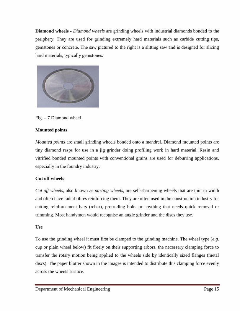
Diamond wheels - Diamond wheels are grinding wheels with industrial diamonds bonded to the
periphery. They are used for grinding extremely hard materials such as carbide cutting tips,
gemstones or concrete. The saw pictured to the right is a slitting saw and is designed for slicing
hard materials, typically gemstones.
Fig. – 7 Diamond wheel
Mounted points
Mounted points are small grinding wheels bonded onto a mandrel. Diamond mounted points are
tiny diamond rasps for use in a jig grinder doing profiling work in hard material. Resin and
vitrified bonded mounted points with conventional grains are used for deburring applications,
especially in the foundry industry.
Cut off wheels
Cut off wheels, also known as parting wheels, are self-sharpening wheels that are thin in width
and often have radial fibres reinforcing them. They are often used in the construction industry for
cutting reinforcement bars (rebar), protruding bolts or anything that needs quick removal or
trimming. Most handymen would recognise an angle grinder and the discs they use.
Use
To use the grinding wheel it must first be clamped to the grinding machine. The wheel type (e.g.
cup or plain wheel below) fit freely on their supporting arbors, the necessary clamping force to
transfer the rotary motion being applied to the wheels side by identically sized flanges (metal
discs). The paper blotter shown in the images is intended to distribute this clamping force evenly
across the wheels surface.

Department of Mechanical Engineering Page 16
Dressing - Grinding wheels are self sharpening to a small degree; for optimal use they may be
dressed and trued by the use of wheel or grinding dressers. Dressing the wheel refers to
removing the current layer of abrasive, so that a fresh and sharp surface is exposed to the work
surface. Trueing the wheel makes the grinding surface parallel to the grinding table or other
reference plane, so that the entire grinding wheel is even and produces an accurate surface.
3.5 Lubrication - The use of fluids in a grinding process is often necessary to cool and
lubricate the wheel and workpiece as well as remove the chips produced in the grinding process.
The most common grinding fluids are water-soluble chemical fluids, water-soluble oils, synthetic
oils, and petroleum-based oils. It is imperative that the fluid be applied directly to the cutting
area to prevent the fluid being blown away from the piece due to rapid rotation of the wheel.
Work
Material Cutting Fluid Application
Aluminum Light-duty oil Flood
Brass Light-duty oil Flood
Cast Iron Heavy-duty emulsifiable oil, light-duty chemical oil, synthetic oil Flood
Mild Steel Heavy-duty water-soluble oil Flood
Stainless
Steel Heavy-duty emulsifiable oil, heavy-duty chemical oil, synthetic oil Flood
Plastics Water-soluble oil, heavy-duty emulsifiable oil, dry, light-duty
chemical oil, synthetic oil Flood
Table 2 – materials using consecutive cutting fluids

Department of Mechanical Engineering Page 17
CHAPTER 4
4.1 Bench Grinder – A bench grinder is a bench-top type of grinding machine used to drive
abrasive wheels. A pedestal grinder is a similar or larger version of grinder that is mounted on a
pedestal, which may be bolted to the floor or may sit on rubber feet. These types of grinders are
commonly used to hand grind various cutting tools and perform other rough grinding.
Depending on the bond and grade of the grinding wheel, it may be used for sharpening cutting
tools such as tool bits, drill bits, chisels, and gouges. Alternatively, it may be used to roughly
shape metal prior to welding or fitting. A wire brush wheel or buffing wheels can be
interchanged with the grinding wheels in order to clean or polish workpieces. Stiff buffing
wheels can also be used when deburring is the task at hand. Some buffing machines (buffers) are
built on the same concept as bench grinders except for longer housings and arbors with buffing
wheels instead of grinding wheels.
Bench grinders are standard equipment in metal fabrication shops and machine shops, as are
handheld grinders (such as angle grinders and die grinders). Wheels come with maximum RPM
ratings printed on the label (paper blotter). The grinder's RPM must be equal or lower; "the
maximum operating speeds indicated on the wheel's tag must never be exceeded
4.1.1 Operation (including safety standards)
Wheel speed - Wheels come with maximum RPM ratings printed on the label (paper blotter).
The grinder's RPM must be equal or lower; "the maximum operating speeds indicated on the
wheel's tag must never be exceeded". Greatly overspeeding a grinding wheel makes it explode,
which can injure or kill the operator like a gunshot would.
Department of Mechanical Engineering Page 18
The typical wheels on most bench grinders are vitreous-bond wheels. They work best to do their
intended task, but they inherently have a risk of cracking. Grinding wheels designed for steel are
not to be used for grinding softer metals, like aluminium. The soft metal gets lodged in the pores
of the wheel and later expands with the heat of grinding. This can dislodge pieces of the grinding
wheel, causing injury.
Sides of wheel versus periphery - Grinding is prohibited on the side of a typical (disk-shaped)
bench grinder wheel, which is designed for grinding on the periphery only. Risk of wheel
explosion otherwise threatens. Some tool and cutter grinders have cup-shaped wheels designed
to do grinding on the side.
Tool rest and spark arrestor placement - The tool rest needs to be tight and within 2 to 3 mm
of the wheel (1/16" to 1/8"). This prevents the workpiece from slipping down between the wheel
and the tool rest. The spark arrestors catch stray sparks. Grinding is usually done with the
workpiece resting on the tool rest. This prevents sudden slips in which the wheel grabs the work
momentarily and yanks it out of the operator's hand or pulls the hand toward the wheel.
Wheel guards - The wheel guards serve to intercept the fragments of an exploding wheel,
keeping them from killing people or damaging surroundings. This is why running a grinder
without the guards is prohibited.
Coolant - Grinding metal on a power-driven grinding wheel quickly heats up the workpiece.
Most bench grinders are of the dry type, in which no cutting fluid (coolant) is used at the
grinding interface, but often the workpiece is recurrently dunked into a pan or pot of water for
cooling so as to keep it from getting hot enough to lose its temper, burn the operator's hand, or
both. Such pots are often mounted just below the grinder for safe and easy reach. For medium-
carbon or high-carbon workpieces that are already hardened and tempered (such as tool bits and
drill bits), the dipping of the piece into the water must be frequent enough to avoid very high
heat followed by substantial quenching, which can easily destroy the existing heat treatment.
Some grinders for knife sharpening duty are of the wet type, in which the bottom of the wheel
runs within a pan of water or other coolant. A tube may also deliver a stream of coolant near the
top of the wheel. These grinders are not always called bench grinders, but they are among the
class of benchtop grinding machines.
Department of Mechanical Engineering Page 19
Wheel dressing - Bench grinder wheels sometimes need to be restored to roundness and given a
fresh grinding face with newly exposed grains. New wheels have suitable balance when first
made, but whether the balanced state will last after the wheel has been mounted, and (especially)
after it has been in use for a while, is "quite uncertain". It can seem counterintuitive that they
could wear as unevenly as they sometimes do, but a slow spin of the resting wheel by hand
confirms it by showing the gap between wheel and tool rest varying substantially as the wheel
turns. Thus it is normal that wheels sometimes need to be dressed (neatly trimmed), which is
achieved by any of several types of wheel dresser. When bench grinders vibrate excessively, it is
usually because the wheels have worn out of round and are thus out of balance. Truing them by
dressing usually resolves this problem. Although some consumers might imagine buying a bench
grinder and then using it for many years without thinking about wheel dressing, the need for
dressing is not so seldom as that. Correcting the imbalance not only reduces the annoyance of
vibration (which rattles the wheel guards and shakes the workbench) but also is important to
prevent premature failure of the spindle bearings, as heavy vibration beats them excessively.
It is also possible to arrange the weight distribution of the wheels for better balancing. There are
several methods of doing this, all being conceptually analogous to tire balancing with wheel
weights. Most bench grinders never have these operations performed, because wheel dressing
alone is enough to keep them sufficiently balanced, but these additional methods are not unusual
for bench grinders and are quite common for machine tools that do grinding, such as surface
grinders and cylindrical grinders. This is sometimes achieved by drilling a few holes in the steel
flanges that hold the grinding wheels and then finding the angular orientation at which the holes'
lack of weight balances out a heavy spot elsewhere on the rotating mass. Another method is a
dedicated type of large flange with little weights that can be screwed down wherever needed for
balancing (called a balancing flange).
Department of Mechanical Engineering Page 20
Wheel replacement - Wheels sometimes need replacing. The grinder is unplugged, and then the
outer guard is removed. Typically a large nut holds the wheel on the arbor. The handedness
(sense) of each nut is assigned to avoid any loosening tendency during grinder use. Thus on a
typical grinder the nut is left-handed on the left side of the grinder from the operator's viewpoint,
with wheel rotation "toward" the operator (if the wheel could travel), whereas on the other side
the nut is right-handed.”
In other words, to remove the nut, it must be turned in the direction that the spindle revolves
when the wheel is in operation." Holding the wheel against the wrench's turning action is
difficult, but usually the wrench is gently tapped with a hammer instead, which neatly taps the
nut loose. A large steel flange is on either side of the wheel, then a paper washer (blotter), then
the wheel. The paper is conventionally held to be absolutely necessary to prevent the steel flange
from bearing directly against the wheel and tending to crack it; trained workers are expected to
know and obey this rule. Thus the entire contact area between flange and wheel is covered, either
with paper or with compressible coating (rubber or gasket) on the flange. The wheel's inner
diameter may meet the arbor precisely or may be larger with a bushing (sleeve) to reduce it.
Before the new wheel is mounted it is ring tested, which involves gently tapping it with a
fingernail or tool handle (wood or plastic) to hear its high-pitched ring (comparable to a bell's
ring, although not loud), indicating that it is not cracked. It is rung in various spots to be sure. A
"flat" or "hoarse" sound (failing to "sing") indicates a crack. With the wheel having passed the
ring test, the bushing (if any), wheel, paper blotters, steel flanges, and nut are assembled, and the
nut is tightened, not as hard as possible, but enough to be firmly fastened in place. The guard is
reinstalled, and then the grinder can be plugged in again. Dressing may be needed afterward.
When the wheel is first started, the operator stands a bit off center, so that if it were to explode,
less pathway for injury exists.
Department of Mechanical Engineering Page 21
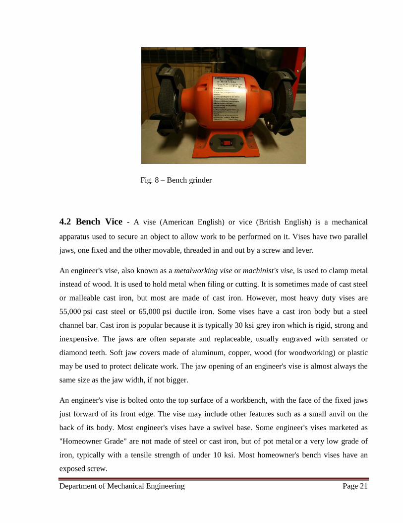
Fig. 8 – Bench grinder
4.2 Bench Vice - A vise (American English) or vice (British English) is a mechanical
apparatus used to secure an object to allow work to be performed on it. Vises have two parallel
jaws, one fixed and the other movable, threaded in and out by a screw and lever.
An engineer's vise, also known as a metalworking vise or machinist's vise, is used to clamp metal
instead of wood. It is used to hold metal when filing or cutting. It is sometimes made of cast steel
or malleable cast iron, but most are made of cast iron. However, most heavy duty vises are
55,000 psi cast steel or 65,000 psi ductile iron. Some vises have a cast iron body but a steel
channel bar. Cast iron is popular because it is typically 30 ksi grey iron which is rigid, strong and
inexpensive. The jaws are often separate and replaceable, usually engraved with serrated or
diamond teeth. Soft jaw covers made of aluminum, copper, wood (for woodworking) or plastic
may be used to protect delicate work. The jaw opening of an engineer's vise is almost always the
same size as the jaw width, if not bigger.
An engineer's vise is bolted onto the top surface of a workbench, with the face of the fixed jaws
just forward of its front edge. The vise may include other features such as a small anvil on the
back of its body. Most engineer's vises have a swivel base. Some engineer's vises marketed as
"Homeowner Grade" are not made of steel or cast iron, but of pot metal or a very low grade of
iron, typically with a tensile strength of under 10 ksi. Most homeowner's bench vises have an
exposed screw.

Department of Mechanical Engineering Page 22
Fig. 9 – Bench vice
Machine - Machine vises are mounted on drill presses, grinding machines and milling machines.
Abrasive chop saws have a special type of machine vise built into the saw. Some hobbyists use a
machine vise as a bench vise because of the low cost and small size.
Vacuum - A vacuum vise is a hobbyist's tool, commonly used to hold circuit boards, model
airplanes and other small work. They are mounted with a suction cup and often have an
articulated joint in the middle to allow the vise to pivot and swivel. Jewelers also use vacuum
vises to hold jewelry.
Pipe - Pipe vises are a plumber's tool, often used to hold pipes in place for threading and cutting.
There are two main styles: chain and yoke. The yoke type vise uses a screw to clamp down the
pipe, and the chain style uses a chain for securing the pipe.

Department of Mechanical Engineering Page 23
Fig. 10 – Heavy duty metalworking vise showing some cosmetic distress and a missing
mounting bolt
Clamp-on - Clamp-on vises are basically very light-duty bench vises. They usually have smooth
jaws for wood, plastic and light metalworking, but some have serrated jaws for getting a better
grip on metal. Some unique vises combine these features in a rotating design. They also help to
secure an object while working on the object.
Combination - Vises that combine the functions of a pipe vise with a metalworker's vise do
exist, and are quite common. Some vises have a rotating design to provide both bench and pipe
jaws. These are often used by plumbers.
Others - Other kinds of vise include:
• Hand vises - compound slide vises are more complex machine vises. They allow speed
and precision in the placement of the work.
Department of Mechanical Engineering Page 24
• Cross vises, which can be adjusted using leadscrews in the X and Y axes; these are useful
if many holes need to be drilled in the same workpiece using a drill press. Compare
router table.
• Off-center vises
• Angle vises
• Sine vises, which use gauge blocks to set up a highly accurate angle
• Rotary vises
• Diemakers' vise
• Saw vices – used for sharpening hand saws
• Pin vises (for holding thin, long cylindrical objects by one end, or used as a drill (scale
modeler's pin vise))
• Jewellers' vises and by contrast
• Leg vises, which are attached to a bench but also supported from the ground so as to be
stable under the very heavy use imposed by a blacksmith's work
• Trailer hitch vice
4.3 – Compressor – An air compressor is a device that converts power (using an electric
motor, diesel or gasoline engine, etc.) into potential energy stored in pressurized air (i.e.,
compressed air). By one of several methods, an air compressor forces more and more air into a
storage tank, increasing the pressure. When tank pressure reaches its upper limit the air
compressor shuts off. The compressed air, then, is held in the tank until called into use. The
energy contained in the compressed air can be used for a variety of applications, utilizing the
kinetic energy of the air as it is released and the tank depressurizes. When tank pressure reaches
its lower limit, the air compressor turns on again and re-pressurizes the tank.

Department of Mechanical Engineering Page 25
Air compressors have many uses, including: supplying high-pressure clean air to fill gas
cylinders, supplying moderate-pressure clean air to a submerged surface supplied diver,
supplying moderate-pressure clean air for driving some office and school building pneumatic
HVAC control system valves, supplying a large amount of moderate-pressure air to power
pneumatic tools, such as jackhammers, filling high pressure air tanks (HPA), for filling tires, and
to produce large volumes of moderate-pressure air for large-scale industrial processes (such as
oxidation for petroleum coking or cement plant bag house purge systems).
Fig. 11 – Air compressor

Department of Mechanical Engineering Page 26
4.3.1 Classification - Compressors can be classified according to the pressure delivered:
Low-pressure air compressors (LPACs), which have a discharge pressure of 150 psi or less
• Medium-pressure compressors which have a discharge pressure of 151 psi to 1,000 psi
• High-pressure air compressors (HPACs), which have a discharge pressure above 1,000
psi
They can also be classified according to the design and principle of operation:
• Rotary-screw compressor
• Turbo compressor
4.3.2 Displacement type - There are numerous methods of air compression, divided into either
positive-displacement or roto-dynamic types.
Positive displacement - Positive-displacement compressors work by forcing air into a chamber
whose volume is decreased to compress the air. Once the maximum pressure is reached, a port or
valve opens and air is discharged into the outlet system from the compression chamber. Common
types of positive displacement compressors are:
Piston-type: air compressors use this principle by pumping air into an air chamber through the
use of the constant motion of pistons. They use one-way valves to guide air into a cylinder
chamber, where the air is compressed.
Rotary screw compressors: use positive-displacement compression by matching two helical
screws that, when turned, guide air into a chamber, whose volume is decreased as the screws
turn.
Vane compressors: use a slotted rotor with varied blade placement to guide air into a chamber
and compress the volume. A type of compressor that delivers a fixed volume of air at high
pressures.
Department of Mechanical Engineering Page 27
Dynamic Displacement - Dynamic displacement air compressors include centrifugal
compressors and axial compressors. In these types, a rotating component imparts its kinetic
energy to the air which is eventually converted into pressure energy. These use centrifugal force
generated by a spinning impeller to accelerate and then decelerate captured air, which pressurizes
it.
4.3.3 Cooling - Due to adiabatic heating, air compressors require some method of disposing of
waste heat. Generally this is some form of air- or water-cooling, although some (particularly
rotary type) compressors may be cooled by oil (that is then in turn air- or water-cooled) and the
atmospheric changes also considered during cooling of compressors.
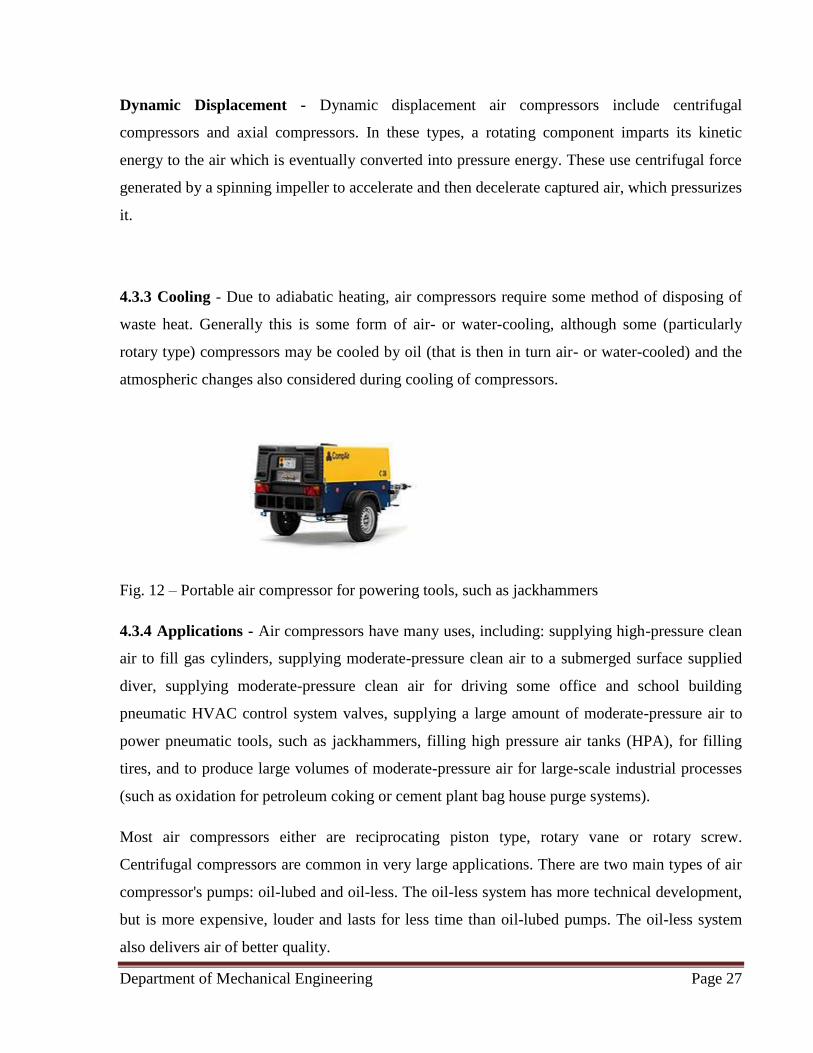
Fig. 12 – Portable air compressor for powering tools, such as jackhammers
4.3.4 Applications - Air compressors have many uses, including: supplying high-pressure clean
air to fill gas cylinders, supplying moderate-pressure clean air to a submerged surface supplied
diver, supplying moderate-pressure clean air for driving some office and school building
pneumatic HVAC control system valves, supplying a large amount of moderate-pressure air to
power pneumatic tools, such as jackhammers, filling high pressure air tanks (HPA), for filling
tires, and to produce large volumes of moderate-pressure air for large-scale industrial processes
(such as oxidation for petroleum coking or cement plant bag house purge systems).
Most air compressors either are reciprocating piston type, rotary vane or rotary screw.
Centrifugal compressors are common in very large applications. There are two main types of air
compressor's pumps: oil-lubed and oil-less. The oil-less system has more technical development,
but is more expensive, louder and lasts for less time than oil-lubed pumps. The oil-less system
also delivers air of better quality.
Department of Mechanical Engineering Page 28
The most common types of air compressors are: electric or gas/diesel powered compressors. The
power of a compressor is measured in HP (horsepower) and CFM (cubic feet per minute of
intake air). The gallon size of the tank specifies the volume of compressed air (in reserve)
available. Gas/diesel powered compressors are widely used in remote areas with problematic
access to electricity. They are noisy and require ventilation for exhaust gases. Electric powered
compressors are widely used in production, workshops and garages with permanent access to
electricity. Common workshop/garage compressors are 110-120 Volt or 230-240 Volt.
Compressor tank shapes are: "pancake", "twin tank", "horizontal", and "vertical". Depending on
a size and purpose compressors can be stationary or portable.
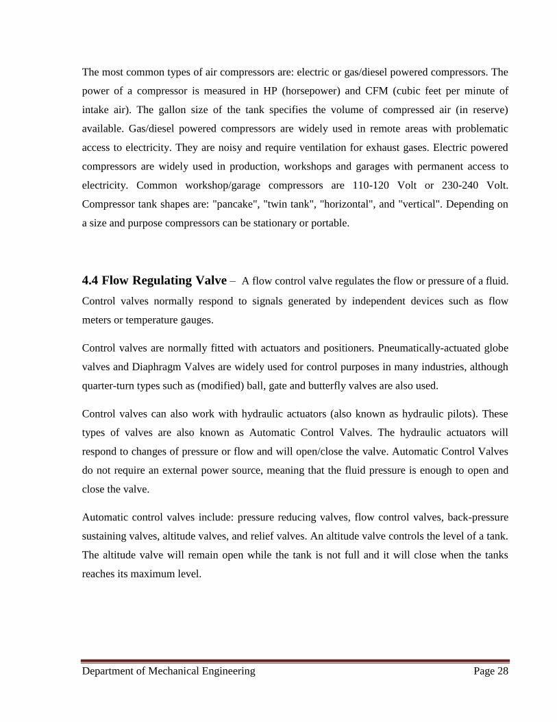
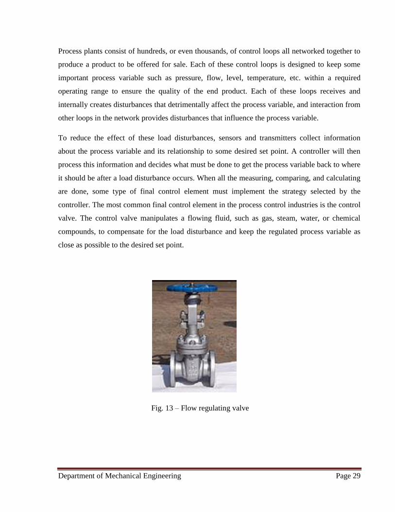
4.4 Flow Regulating Valve – A flow control valve regulates the flow or pressure of a fluid.
Control valves normally respond to signals generated by independent devices such as flow
meters or temperature gauges.
Control valves are normally fitted with actuators and positioners. Pneumatically-actuated globe
valves and Diaphragm Valves are widely used for control purposes in many industries, although
quarter-turn types such as (modified) ball, gate and butterfly valves are also used.
Control valves can also work with hydraulic actuators (also known as hydraulic pilots). These
types of valves are also known as Automatic Control Valves. The hydraulic actuators will
respond to changes of pressure or flow and will open/close the valve. Automatic Control Valves
do not require an external power source, meaning that the fluid pressure is enough to open and
close the valve.
Automatic control valves include: pressure reducing valves, flow control valves, back-pressure
sustaining valves, altitude valves, and relief valves. An altitude valve controls the level of a tank.
The altitude valve will remain open while the tank is not full and it will close when the tanks
reaches its maximum level.
Department of Mechanical Engineering Page 29
Process plants consist of hundreds, or even thousands, of control loops all networked together to
produce a product to be offered for sale. Each of these control loops is designed to keep some
important process variable such as pressure, flow, level, temperature, etc. within a required
operating range to ensure the quality of the end product. Each of these loops receives and
internally creates disturbances that detrimentally affect the process variable, and interaction from
other loops in the network provides disturbances that influence the process variable.
To reduce the effect of these load disturbances, sensors and transmitters collect information
about the process variable and its relationship to some desired set point. A controller will then
process this information and decides what must be done to get the process variable back to where
it should be after a load disturbance occurs. When all the measuring, comparing, and calculating
are done, some type of final control element must implement the strategy selected by the
controller. The most common final control element in the process control industries is the control
valve. The control valve manipulates a flowing fluid, such as gas, steam, water, or chemical
compounds, to compensate for the load disturbance and keep the regulated process variable as
close as possible to the desired set point.
Fig. 13 – Flow regulating valve

Department of Mechanical Engineering Page 30
4.5 Mild Steel Sheet - Mild steel is a type of carbon steel with a low amount of carbon – it is
actually also known as “low carbon steel.” Although ranges vary depending on the source, the
amount of carbon typically found in mild steel is 0.05% to 0.25% by weight, whereas higher
carbon steels are typically described as having a carbon content from 0.30% to 2.0%. If any more
carbon than that is added, the steel would be classified as cast iron. Mild steel is not an alloy
steel and therefore does not contain large amounts of other elements besides iron; you will not
find vast amounts of chromium, molybdenum, or other alloying elements in mild steel. Since its
carbon and alloying element content are relatively low, there are several properties it has that
differentiate it from higher carbon and alloy steels.
Less carbon means that mild steel is typically more ductile, machinable, and weld able than high
carbon and other steels, however, it also means it is nearly impossible to harden and strengthen
through heating and quenching. The low carbon content also means it has very little carbon and
other alloying elements to block dislocations in its crystal structure, generally resulting in less
tensile strength than high carbon and alloy steels. Mild steel also has a high amount iron and
ferrite, making it magnetic.
The lack of alloying elements such as those found in stainless steels means that the iron in mild
steel is subject to oxidation (rust) if not properly coated. But the negligible amount of alloying
elements also helps mild steel to be relatively affordable when compared with other steels. It is
the affordability, weldability, and machinability that make it such a popular choice of steel for
consumers.
Department of Mechanical Engineering Page 31
CHAPTER 5
5.1 Pneumatics – Pneumatics is a branch of engineering that makes use of gas or pressurized
air. Pneumatic systems used in industry are commonly powered by compressed air or
compressed inert gases. A centrally located and electrically powered compressor powers
cylinders, air motors, and other pneumatic devices. A pneumatic system controlled through
manual or automatic solenoid valves is selected when it provides a lower cost, more flexible, or
safer alternative to electric motors and actuators.
Pneumatics also has applications in dentistry, construction, mining, and other areas.
5.1.1. History - The origins of pneumatics can be traced back to the first century when ancient
Greek mathematician Hero of Alexandria wrote about his inventions powered by steam or the
wind. German physicist Otto von Guericke (1602 to 1686) went a little further. He invented the
vacuum pump, a device that can draw out air or gas from the attached vessel. He demonstrated
the vacuum pump to separate the pairs of copper hemispheres using air pressures. The field of
pneumatics has changed considerably over the years. It has moved from small handheld devices
to large machines with multiple parts that serve different functions.
5.1.2 Comparison to hydraulics - Both pneumatics and hydraulics are applications of fluid
power. Pneumatics uses an easily compressible gas such as air or a suitable pure gas—while
hydraulics uses relatively incompressible liquid media such as oil. Most industrial pneumatic
applications use pressures of about 80 to 100 pounds per square inch (550 to 690 kPa).
Hydraulics applications commonly use from 1,000 to 5,000 psi (6.9 to 34.5 MPa), but
specialized applications may exceed 10,000 psi (69 MPa).
5.1.3 Advantages of pneumatics
• Simplicity of design and control—Machines are easily designed using standard cylinders
and other components, and operate via simple on-off control.
Department of Mechanical Engineering Page 32
• Reliability—Pneumatic systems generally have long operating lives and require little
maintenance. Because gas is compressible, equipment is less subject to shock damage.
Gas absorbs excessive force, whereas fluid in hydraulics directly transfers force.
Compressed gas can be stored, so machines still run for a while if electrical power is lost.
• Safety—There is a very low chance of fire compared to hydraulic oil. Newer machines
are usually overload safe.
5.1.4 Gases used in pneumatic systems - Pneumatic systems in fixed installations, such as
factories, use compressed air because a sustainable supply can be made by compressing
atmospheric air. The air usually has moisture removed, and a small quantity of oil is added at the
compressor to prevent corrosion and lubricate mechanical components.
Factory-plumbed pneumatic-power users need not worry about poisonous leakage, as the gas is
usually just air. Smaller or stand-alone systems can use other compressed gases that present an
asphyxiation hazard, such as nitrogen—often referred to as OFN (oxygen-free nitrogen) when
supplied in cylinders.
Any compressed gas other than air is an asphyxiation hazard—including nitrogen, which makes
up 78% of air. Compressed oxygen (approx. 21% of air) would not asphyxiate, but is not used in
pneumatically-powered devices because it is a fire hazard, more expensive, and offers no
performance advantage over air. Portable pneumatic tools and small vehicles, such as Robot
Wars machines and other hobbyist applications are often powered by compressed carbon
dioxide, because containers designed to hold it such as soda stream canisters and fire
extinguishers are readily available, and the phase change between liquid and gas makes it
possible to obtain a larger volume of compressed gas from a lighter container than compressed
air requires. Carbon dioxide is an asphyxiant and can be a freezing hazard if vented improperly.
5.1.5 Pneumatic logic - Pneumatic logic systems (sometimes called air logic control) are
sometimes used for controlling industrial processes, consisting of primary logic units like:
• And Units
• Or Units

Department of Mechanical Engineering Page 33
• 'Relay or Booster' Units
• Latching Units
• 'Timer' Units
• Sorteberg relay
Fluidics amplifiers with no moving parts other than the air itself. Pneumatic logic is a reliable
and functional control method for industrial processes. In recent years, these systems have
largely been replaced by electronic control systems in new installations because of the smaller
size, lower cost, greater precision, and more powerful features of digital controls. Pneumatic
devices are still used where upgrade cost, or safety factors dominate.
5.2 Working of Pneumatic Cylinder – Pneumatic cylinder(s) (sometimes known as air
cylinders) are mechanical devices which use the power of compressed gas to produce a force in a
reciprocating linear motion. Like hydraulic cylinders, something forces a piston to move in the
desired direction. The piston is a disc or cylinder, and the piston rod transfers the force it
develops to the object to be moved. Engineers sometimes prefer to use pneumatics because they
are quieter, cleaner, and do not require large amounts of space for fluid storage.
Because the operating fluid is a gas, leakage from a pneumatic cylinder will not drip out and
contaminate the surroundings, making pneumatics more desirable where cleanliness is a
requirement
5.2.1. Operation - Once actuated, compressed air enters into the tube at one end of the piston
and, hence, imparts force on the piston. Consequently, the piston becomes displaced.
Department of Mechanical Engineering Page 34
5.2.2 Compressibility of gasses - One major issue engineers come across working with
pneumatic cylinders has to do with the compressibility of a gas. Many studies have been
completed on how the precision of a pneumatic cylinder can be affected as the load acting on the
cylinder tries to further compress the gas used. Under a vertical load, a case where the cylinder
takes on the full load, the precision of the cylinder is affected the most. A study at the National
Cheng Kung University in Taiwan, concluded that the accuracy is about ± 30 nm, which is still
within a satisfactory range but shows that the compressibility of air has an effect on the system.
5.2.3 Fail safe mechanisms - Pneumatic systems are often found in settings where even rare and
brief system failure is unacceptable. In such situations locks can sometimes serve as a safety
mechanism in case of loss of air supply (or its pressure falling) and, thus remedy or abate any
damage arising in such a situation. Leakage of air from the input or output reduces the pressure
and so the desired output.
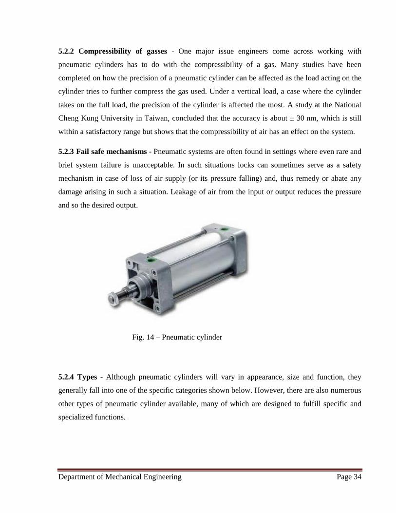
Fig. 14 – Pneumatic cylinder
5.2.4 Types - Although pneumatic cylinders will vary in appearance, size and function, they
generally fall into one of the specific categories shown below. However, there are also numerous
other types of pneumatic cylinder available, many of which are designed to fulfill specific and
specialized functions.
Department of Mechanical Engineering Page 35
Single-acting cylinders - Single-acting cylinders (SAC) use the pressure imparted by
compressed air to create a driving force in one direction (usually out), and a spring to return to
the "home" tion. More often than not, this type of cylinder has limited extension due to the space
the compressed spring takes up. Another downside to SACs is that part of the force produced by
the cylinder is lost as it tries to push against the spring
Double-acting cylinders - Double-acting cylinders (DAC) use the force of air to move in both
extend and retract strokes. They have two ports to allow air in, one for outstroke and one for
instroke. Stroke length for this design is not limited, however, the piston rod is more vulnerable
to buckling and bending. Additional calculations should be performed as well.
Multi-stage, telescoping cylinder -Telescoping cylinders, also known as telescopic cylinders
can be either single or double-acting. The telescoping cylinder incorporates a piston rod nested
within a series of hollow stages of increasing diameter. Upon actuation, the piston rod and each
succeeding stage "telescopes" out as a segmented piston. The main benefit of this design is the
allowance for a notably longer stroke than would be achieved with a single-stage cylinder of the
same collapsed (retracted) length. One cited drawback to telescoping cylinders is the increased
potential for piston flexion due to the segmented piston design. Consequently, telescoping
cylinders are primarily utilized in applications where the piston bears minimal side loading.
5.2.5. Pressure, radius, area and force relationships -
Rod stresses - Due to the forces acting on the cylinder, the piston rod is the most stressed
component and has to be designed to withstand high amounts of bending, tensile and
compressive forces. Depending on how long the piston rod is, stresses can be calculated
differently. If the rods length is less than 10 times the diameter, then it may be treated as a rigid
body which has compressive or tensile forces acting on it. In which case the relationship is:
F = AS
Where:
F is the compressive or tensile force
A is the cross-sectional area of the piston rod

Department of Mechanical Engineering Page 36
S is the stress
However, if the length of the rod exceeds the 10 times the value of the diameter, then the rod
needs to be treated as a column and buckling needs to be calculated as well.
Instroke and outstroke - Although the diameter of the piston and the force exerted by a cylinder
are related, they are not directly proportional to one another. Additionally, the typical
mathematical relationship between the two assumes that the air supply does not become
saturated. Due to the effective cross sectional area reduced by the area of the piston rod, the
instroke force is less than the outstroke force when both are powered pneumatically and by same
supply of compressed gas.
The relationship between the force, radius, and pressure can derived from simple distributed load
equation:
Fr = P*Ae
Where:
Fr is the resultant force
P is the pressure or distributed load on the surface
Ae is the effective cross sectional area the load is acting on
Outstroke
Using the distributed load equation provided that can be replaced with area of the piston surface
where the pressure is acting on.
Fr = P*3.14*r2
Where:
Fr represents the resultant force
P represents the radius of the piston
Department of Mechanical Engineering Page 37
Instroke - On instroke, the same relationship between force exerted, pressure and effective cross
sectional area applies as discussed above for outstroke. However, since the cross sectional area
is less than the piston area the relationship between force, pressure and radius is different. The
calculation isn't more complicated though, since the effective cross sectional area is merely that
of the piston surface minus the cross sectional area of the piston rod.
For instroke, therefore, the relationship between force exerted, pressure, radius of the piston, and
radius of the piston rod, is as follows:
Fr = P*3.14(r12 - r2
2)
Where:
Fr represents the resultant force
r 1 represents the radius of the piston
r2 represents the radius of the piston rod
5.3. Working of Solenoid Valve – A solenoid valve is an electromechanically operated
valve. The valve is controlled by an electric current through a solenoid: in the case of a two-port
valve the flow is switched on or off; in the case of a three-port valve, the outflow is switched
between the two outlet ports. Multiple solenoid valves can be placed together on a manifold.
Solenoid valves are the most frequently used control elements in fluidics. Their tasks are to shut
off, release, dose, distribute or mix fluids. They are found in many application areas. Solenoids
offer fast and safe switching, high reliability, long service life, good medium compatibility of the
materials used, low control power and compact design. Besides the plunger-type actuator which
is used most frequently, pivoted-armature actuators and rocker actuators are also used.

Department of Mechanical Engineering Page 38
Fig. 15 – Working of solenoid valve
There are many valve design variations. Ordinary valves can have many ports and fluid paths. A
2-way valve, for example, has 2 ports; if the valve is open, then the two ports are connected and
fluid may flow between the ports; if the valve is closed, then ports are isolated. If the valve is
open when the solenoid is not energized, then the valve is termed normally open (N.O.).
Similarly, if the valve is closed when the solenoid is not energized, then the valve is termed
normally closed. There are also 3-way and more complicated designs. A 3-way valve has 3 ports;
it connects one port to either of the two other ports (typically a supply port and an exhaust port).
Solenoid valves are also characterized by how they operate. A small solenoid can generate a
limited force.

Department of Mechanical Engineering Page 39
If that force is sufficient to open and close the valve, then a direct acting solenoid valve is
possible. An approximate relationship between the required solenoid force Fs, the fluid pressure
P, and the orifice area A for a direct acting solenoid value is
Fs = PA = P*3.14*D2 / 4
Where d is the orifice diameter. A typical solenoid force might be 15 N (3.4 lbf). An application
might be a low pressure (e.g., 10 psi (69 kPa)) gas with a small orifice diameter (e.g., 3⁄8 in
(9.5 mm) for an orifice area of 0.11 in2 (7.1×10⁻⁵ m2) and approximate force of 1.1 lbf (4.9 N)).
The solenoid valve (small black box at the top of the photo) with input air line (small green tube)
used to actuate a larger rack and pinion actuator (gray box) which controls the water pipe valve.
When high pressures and large orifices are encountered, then high forces are required. To
generate those forces, an internally piloted solenoid valve design may be possible. In such a
design, the line pressure is used to generate the high valve forces; a small solenoid controls how
the line pressure is used. Internally piloted valves are used in dishwashers and irrigation systems
where the fluid is water, the pressure might be 80 pounds per square inch (550 kPa) and the
orifice diameter might be 3⁄4 in (19 mm). In some solenoid valves the solenoid acts directly on
the main valve. Others use a small, complete solenoid valve, known as a pilot, to actuate a larger
valve. While the second type is actually a solenoid valve combined with a pneumatically
actuated valve, they are sold and packaged as a single unit referred to as a solenoid valve. Piloted
valves require much less power to control, but they are noticeably slower. Piloted solenoids
usually need full power at all times to open and stay open, where a direct acting solenoid may
only need full power for a short period of time to open it, and only low power to hold it. A direct
acting solenoid valve typically operates in 5 to 10 milliseconds. The operation time of a piloted
valve depends on its size; typical values are 15 to 150 milliseconds. Power consumption and
supply requirements of the solenoid vary with application, being primarily determined by fluid
pressure and line diameter. For example, a popular 3/4" 150 psi sprinkler valve, intended for 24
VAC (50 - 60 Hz) residential systems, has a momentary inrush of 7.2 VA, and a holding power
requirement of 4.6 VA. Comparatively, an industrial 1/2" 10000 psi valve, intended for 12, 24, or
120 VAC systems in high pressure fluid and cryogenic applications, has an inrush of 300 VA
and a holding power of 22 VA. Neither valve lists a minimum pressure required to remain closed
in the un-powered state.
Department of Mechanical Engineering Page 40
5.4 - Feed of the work piece - A leadscrew (or lead screw), also known as a power screw
or translation screw, is a screw used as a linkage in a machine, to translate turning motion into
linear motion. Because of the large area of sliding contact between their male and female
members, screw threads have larger frictional energy losses compared to other linkages. They
are not typically used to carry high power, but more for intermittent use in low power actuator
and positioner mechanisms. Common applications are linear actuators, machine slides (such as in
machine tools), vises, presses, and jacks.
Leadscrews are manufactured in the same way as other thread forms (they may be rolled, cut, or
ground). A lead screw is sometimes used with a split nut also called half nut which allows the
nut to be disengaged from the threads and moved axially, independently of the screw's rotation,
when needed (such as in single-point threading on a manual lathe).
5.4.1 Types - Power screws are classified by the geometry of their thread. V-threads are less
suitable for leadscrews than others such as ACME because they have more friction between the
threads. Their threads are designed to induce this friction to keep the fastener from loosening.
Leadscrews, on the other hand, are designed to minimize friction. Therefore, in most commercial
and industrial use, V-threads are avoided for leadscrew use. Nevertheless, V-threads are
sometimes successfully used as leadscrews, for example on microlathes and micromills.
Square thread - Square threads are named after their square geometry. They are the most
efficient, having the least friction, so they are often used for screws that carry high power. But
they are also the most difficult to machine, and are thus the most expensive.
Acme thread - Acme threads have a 29° thread angle, which is easier to machine than square
threads. They are not as efficient as square threads, due to the increased friction induced by the
thread angle. ACME Threads are generally also stronger than square threads due to their
trapezoidal thread profile, which provides greater load-bearing capabilities.

Department of Mechanical Engineering Page 41
Fig. 16 – An Acme screw
Buttress thread - Buttress threads are of a triangular shape. These are used where the load force
on the screw is only applied in one direction. They are as efficient as square threads in these
applications, but are easier to manufacture.
Fig. 17 – Leadscrews are used to raise and lower the front door of the Boeing 747-8F Freighter
aircraft.
5.4.2 Advantages & disadvantages
The advantages of a leadscrew are:
• Large load carrying capability
• Compact
• Simple to design
• Easy to manufacture; no specialized machinery is required
• Large mechanical advantage
• Precise and accurate linear motion
• Smooth, quiet, and low maintenance
Department of Mechanical Engineering Page 42
• Minimal number of parts
• Most are self-locking
The disadvantages are that most are not very efficient. Due to the low efficiency they cannot be
used in continuous power transmission applications. They also have a high degree of friction on
the threads, which can wear the threads out quickly. For square threads, the nut must be replaced;
for trapezoidal threads, a split nut may be used to compensate for the wear.
Alternatives - Alternatives to actuation by leadscrew include:
• Ball screws and roller screws (sometimes categorized as types of leadscrew rather than in
contradistinction)
• Fluid power (i.e., hydraulics and pneumatics)
• Gear trains (e.g., worm drives, rack-and-pinion drives)
• Electromagnetic actuation (e.g., solenoids)
• Piezoelectric actuation
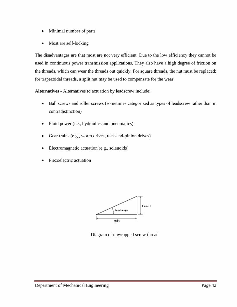
Diagram of unwrapped screw thread
Department of Mechanical Engineering Page 43
Mechanics - The torque required to lift or lower a load can be calculated by "unwrapping" one
revolution of a thread. This is most easily described for a square or buttress thread as the thread
angle is 0 and has no bearing on the calculations. The unwrapped thread forms a right angle
triangle where the base is long and the height is the lead (pictured to the right). The force of the
load is directed downward, the normal force is perpendicular to the hypotenuse of the triangle,
the frictional force is directed in the opposite direction of the direction of motion (perpendicular
to the normal force or along the hypotenuse), and an imaginary "effort" force is acting
horizontally in the direction opposite the direction of the frictional force.
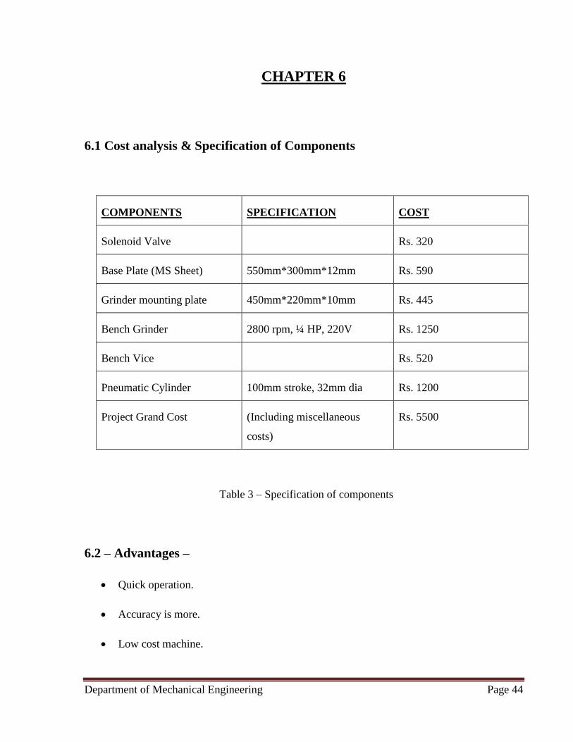
Department of Mechanical Engineering Page 44
CHAPTER 6
6.1 Cost analysis & Specification of Components
COMPONENTS SPECIFICATION COST
Solenoid Valve Rs. 320
Base Plate (MS Sheet) 550mm*300mm*12mm Rs. 590
Grinder mounting plate 450mm*220mm*10mm Rs. 445
Bench Grinder 2800 rpm, ¼ HP, 220V Rs. 1250
Bench Vice Rs. 520
Pneumatic Cylinder 100mm stroke, 32mm dia Rs. 1200
Project Grand Cost (Including miscellaneous
costs)
Rs. 5500
Table 3 – Specification of components
6.2 – Advantages –
• Quick operation.
• Accuracy is more.
• Low cost machine.
Department of Mechanical Engineering Page 45
• Simple in construction.
• Less maintenance.
• Reduces manual work
6.3 – Application –
Can be implemented in industries which utilise materials such as -
• Plastic and rubber.
• Stone, ceramics and glass.
• Leather and metal.
6.4 – Limitations
Leakage of air affects the working of the unit.
Costlier than manual grinding because of compressor unit but it can be cut-short if
compressor is already employed.
Only small sized jobs can be ground.

Department of Mechanical Engineering Page 46
CHAPTER-7
7.1 Conclusion
As per the above discussion we concluded that to overcome problems in conventional grinding
machines, due to high efficiency, easy to operate and affordable price the proposed model of
solenoid operated pneumatic grinding machine is helpful and completes all the expectations
needed in the mini industries. Future scope of proposed research work is to increase the
production rate, grind the metal jobs easily. It can withstand the vibrations, there areno hazards
from jerk, no special training required to operate it.
After studying this report we have known that how the pneumatic grinding machine will work,
and knowing the construction and how the mechanism works in the machine. We learnt how the
theoretical design is possible in practical. Other grinding machines require operator to manually
perform the process but this proposed arrangement does it automatically, this grinding machine
has lighter weight compared to other machines. The cost of machine is less and easy to operate
so it is affordable for all industries.
7.2 Future Scope
• The forward stroke can be increased by using a superior cylinder for grinding longer jobs
by increasing the pressure production capacity of the compressor
• Automatic feeding mechanism for material can be introduced by using limit switches or
sensors.
• Automatic lifting up mechanism for job when grinding operation is finished to introduce
next portion of job for grinding.
Department of Mechanical Engineering Page 47
References
1) Brian S. Elliott, Compressed Air Operations Manual, McGraw Hill Book Company,
2006, ISBN 0-07-147526-5.
2) Heeresh Mistry, Fundamentals of Pneumatic Engineering, Create Space e-Publication,
2013, ISBN 1-49-372758-3.
3) Krar, Gill & Smid 2003
4) "How Do Air Compressors Work?". Popular Mechanics. 2015-03-18. Retrieved 2017-01-
12.
5) "Compressor Selection Basics: Positive Displacement versus Dynamic Compression".
Retrieved 2017-01-12 – via The 5th Utility.
6) Majumdar, S.R. (1995). Pneumatic System: Principles and Maintenance. New Delhi:
Tata McGraw-Hill.
7) Ball Screws & Lead screws, retrieved 2008-12-16.
8) Haan, E. R. (October 1954), "Selecting and using a bench vise", Popular Mechanics, 102
(4): 233–235, ISSN 0032-4558.