Embed Size (px)
Citation preview
Solar Power Installations on Closed Landfills: Technical and Regulatory Considerations
September 2009
Prepared by:
Gabriel Sampson National Network of Environmental Management Studies Fellow
Bren School of Environmental Science and Management University of California, Santa Barbara
for
U.S. Environmental Protection Agency
Office of Solid Waste and Emergency Response Office of Superfund Remediation and Technology Innovation
Washington, D.C. www.epa.gov www.clu-in.org

Solar Power Installations on Closed Landfills: Technical and Regulatory Considerations
i
NOTICE
This document was prepared by a National Network for Environmental Management Studies (NNEMS) grantee under a fellowship from the U.S. Environmental Protection Agency (EPA). This report was not subject to EPA peer review or technical review. The EPA makes no warranties, expressed or implied, including without limitation, warranty for completeness, accuracy, or usefulness of the information, warranties as to the merchantability, or fitness for a particular purpose. Moreover, the listing of any technology, corporation, company, person, or facility in this report does not constitute endorsement, approval, or recommendation by the EPA. The report contains information attained from a wide variety of currently available sources, including project documents, reports, periodicals, Internet websites, and personal communication with both academically and commercially employed sources. No attempts were made to independently confirm the resources used. It has been reproduced to help provide federal agencies, states, consulting engineering firms, private industries, and technology developers with information on the current status of this project. About the National Network for Environmental Management Studies
The NNEMS is a comprehensive fellowship program managed by the Environmental Education Division of EPA. The purpose of the NNEMS Program is to provide students with practical research opportunities and experiences. Each participating headquarters or regional office develops and sponsors projects for student research. The projects are narrow in scope to allow the student to complete the research by working full-time during the summer or part-time during the school year. Research fellowships are available in Environmental Policy, Regulations and Law; Environmental Management and Administration; Environmental Science; Public Relations and Communications; and Computer Programming and Development. NNEMS fellows receive a stipend determined by the student’s level of education and the duration of the research project. Fellowships are offered to undergraduate and graduate students. Students must meet certain eligibility criteria.
Solar Power Installations on Closed Landfills: Technical and Regulatory Considerations
ii
TABLE OF CONTENTS
EXECUTIVE SUMMARY ........................................................................................................... V
1. INTRODUCTION .............................................................................................................. 1
2. SOLAR POWER SYSTEMS ............................................................................................. 1
2.1. Introduction to Ground Mounted Systems.................................................................. 2
2.2. Different Solar Technologies...................................................................................... 3
2.3. Solar System Weight Considerations ......................................................................... 6
2.4. Wind Loading and Snow Loading .............................................................................. 9
3. TECHNICAL CHALLENGES........................................................................................... 9
3.1. Settlement ................................................................................................................... 9
3.2. Cover Material Integrity ........................................................................................... 11
3.3. Side Slope Stability................................................................................................... 12
3.4. Renewable Energy Production on Superfund or Brownfield Sites........................... 13
3.5. Summary of Technical Complications, Challenges, and Potential Remedies .......... 13
4. REGULATORY CHALLENGES .................................................................................... 14
4.1. Required Permitting .................................................................................................. 15
4.2. Zoning and Land Use................................................................................................ 18
4.3. Existing Contamination and Environmental Site Investigations .............................. 18
4.4. CERCLA Liability .................................................................................................... 19
5. CONCLUSIONS............................................................................................................... 21
6. REFERENCES ................................................................................................................. 22
APPENDIX A: CASE STUDIES ............................................................................................... A-1
Solar Power Installations on Closed Landfills: Technical and Regulatory Considerations
iii
LIST OF FIGURES Figure 1 Fixed tilt A-frame style ground-mounted PV system 2
Figure 2 Fixed tilt PV solar array at Fort Carson, CO 3
Figure 3 Single axis sun-tracking mounting structure, concrete footings, support beams,
and PV panels at Nellis Air Force Base, NV 4
Figure 4 Parabolic trough linear concentrator mirrors 5
Figure 5 Power tower solar system in southern California 5
Figure 6 Dish/engine solar system 6
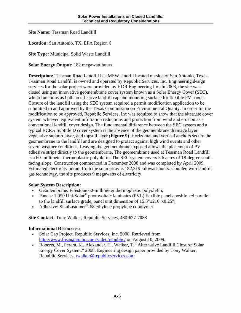
Figure 7 Flexible PV laminates on the Tessman Road Landfill near 7
Figure 8 Pre-cast concrete footing used as foundation on side slope at Pennsauken
Landfill, NJ 12
Figure 9 SEC system (left) compared to a typical RCRA Subtitle D cover system (right) 18
LIST OF TABLES
Table 1 Weight specifications for various PV panels 8
Table 2 Engineering complications and potential remedies 14
Table 3 List of states with various levels of brownfields liability protection 21
Solar Power Installations on Closed Landfills: Technical and Regulatory Considerations
iv
LIST OF ABBREVIATIONS
AFB Air Force Base BFPP Bona Fide Prospective Purchaser CERCLA Comprehensive Environmental Response and Liability Act CLP Closed Landfill Program CSP Concentrating Solar Power DOE United States Department of Energy EA Expenditure Account EPA United States Environmental Protection Agency ESI Environmental Site Investigation MPCA Minnesota Pollution Control Agency MSW Municipal Solid Waste OSRTI Office of Superfund Remediation and Technology Innovation OSWER Office of Solid Waste and Emergency Response PCFACC Pollution Control Financing Authority of Camden County PLA Prospective Leaser Agreement PPA Prospective Purchaser Agreement RCRA Resource Conservation and Recovery Act RWQCB Regional Water Quality Control Board SEC Solar Energy Cover SVOCs Semi Volatile Organic Compounds SWMU Solid Waste Management Unit TCEQ Texas Commission on Environmental Quality VOCs Volatile Organic Compounds
Solar Power Installations on Closed Landfills: Technical and Regulatory Considerations
v
EXECUTIVE SUMMARY Development of contaminated lands in general and closed landfills in particular for the placement of renewable energy is a relatively new and growing practice. While the benefits of developing contaminated lands are well established, recurring challenges and limited literature on the subject are believed to complicate the practice. This project provides an overview of the technical and regulatory facets of constructing solar farms on closed landfills. Through a combination of case study evidence and literature research, this paper presents an examination of the current complications to placing solar systems on closed landfills while also providing applications for additional study in the area of landfill and contaminated lands development. The target audience for this study includes project managers, owners, developers, operators, regulators, and various levels of stakeholders with an interest in revitalizing contaminated lands. This paper examines the current nature of solar energy developments on closed landfills using the following focal areas: (1) solar power system considerations with respect to landfill applications, (2) landfill technical and engineering considerations, and (3) regulatory considerations. Research results indicate that numerous engineering techniques and solar technologies are available to facilitate the placement of solar energy systems on closed landfills. Results also indicate that the permitting and regulatory process is complicated by disparate but specific state and local government requirements. Though this study focuses narrowly on the technical and regulatory affairs of constructing solar farms on closed landfills, it also has applications to the placement of solar energy systems in broader settings. The views detailed in this study are designed to inform decision makers and stakeholders and to facilitate the design, construction, and operation of future solar installations on closed landfills.
Solar Power Installations on Closed Landfills: Technical and Regulatory Considerations
1
1. INTRODUCTION Since 1988 the number of municipal solid waste (MSW) landfills in the U.S. has decreased from 7,924 to 1,754. Accordingly, at least 6,170 landfills have closed over the past two decades. Estimates for the total number of closed landfills in the United States are as high as 100,000 (Suflita et al, 1992). This roughly estimated number of landfills represents hundreds of thousands of acres of brownfields real property. As demand for new land increases, landfills are becoming valuable for their development potential (EPA, 2002). The U.S. Environmental Protection Agency (EPA) Office of Solid Waste and Emergency Response (OSWER) Center for Program Analysis is encouraging the reuse of contaminated lands, including properties with closed landfills, for siting clean and renewable energy facilities. Contaminated lands encompass sites that are undergoing remediation or have completed remediation under various cleanup programs, such as Superfund and brownfield sites. Through the Re-Powering America’s Lands Initiative, OSWER has identified several important reasons for siting clean and renewable energy facilities on contaminated lands, including: Contaminated lands offer thousands of acres of open space in areas where solar
installations may be less likely to involve community concerns over aesthetic impacts; Contaminated lands may have lower overall transaction costs than greenfield sites; Development of brownfields can assuage the stress placed on greenfields to site clean and
renewable energy facilities; Contaminated lands may have environmental conditions that are not well suited for
commercial or residential zoning or otherwise have low demand for real estate development (EPA, 2008).
Electricity generated from renewable energy projects on contaminated or remediated lands can then be used onsite or sold or credited for offsite use. The current OSWER Initiative to site renewable and clean energy on contaminated lands has a number of benefits. However, information on the technical and regulatory contexts of siting solar energy facilities on Superfund and brownfield sites, and over closed landfills in particular, is dispersed and difficult to find. EPA’s Office of Superfund Remediation and Technology Innovation (OSRTI) has identified this challenge as one frequently faced by stakeholders and regulators seeking to properly carry out renewable energy installations on contaminated lands. This paper outlines the technical and regulatory challenges to placing solar systems on closed landfills, with a particular focus on system placement at Superfund and brownfield sites, and provides case evidence of successful solar system planning and construction. 2. SOLAR POWER SYSTEMS There are a fairly wide set of considerations that are important when planning a solar system to be placed over a closed landfill. With respect to the solar technologies available, considerations include whether concentrating solar power (CSP) or photovoltaic (PV) will be best suited to site- specific conditions. Additional factors to consider during the planning process, given the constraints of building on a landfill cap, are the desired output capacity, weight characteristics, and degree of mechanical stress expected from onsite weather conditions. This section provides
Solar Power Installations on Closed Landfills: Technical and Regulatory Considerations
2
an introduction to ground mounted solar systems followed by a discussion of the different solar technologies available, weight characteristics, and wind and snow loading as they apply to landfill installations. 2.1. Introduction to Ground Mounted Systems Installation of a solar energy system on a landfill cap will require the use of ground mounted solar arrays. Ground mounted solar systems often involve aluminum or galvanized steel framing that is attached to a concrete foundation. The concrete foundation can also be referred to as a pier or footing and the panel supports can be referred to as stanchions. With respect to footings, several designs are available: Shallow poured concrete pillars; Pre-fabricated concrete; Slab; Ballast frames; Driven pile; and Earth screw augers.
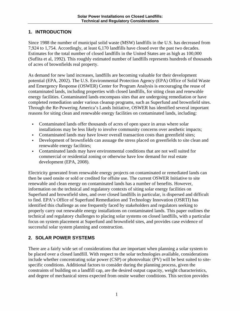
Weight considerations for the various types of footings are discussed in Section 2.3. The simplest solar mounting structures resemble an A-frame, with vertical stanchions secured to a foundation supporting the solar panels (Figure 1 and Figure 2). More elegant mounting structures have axes that move to track the movement of the sun (Figure 3, Section 2.2). In Figure 1, the aluminum support stanchions supporting the PV panels can be seen on the right. The aluminum stanchions are secured to pillar-shaped ground penetrating concrete footings in the front and rear. The preceding discussion is relevant to PV solar systems. Comparison of PV systems to alternate solar technologies is discussed in further detail in the following section. Figure 1. Fixed tilt A-frame style ground mounted PV system
Source: flickr.com
Solar Power Installations on Closed Landfills: Technical and Regulatory Considerations
3
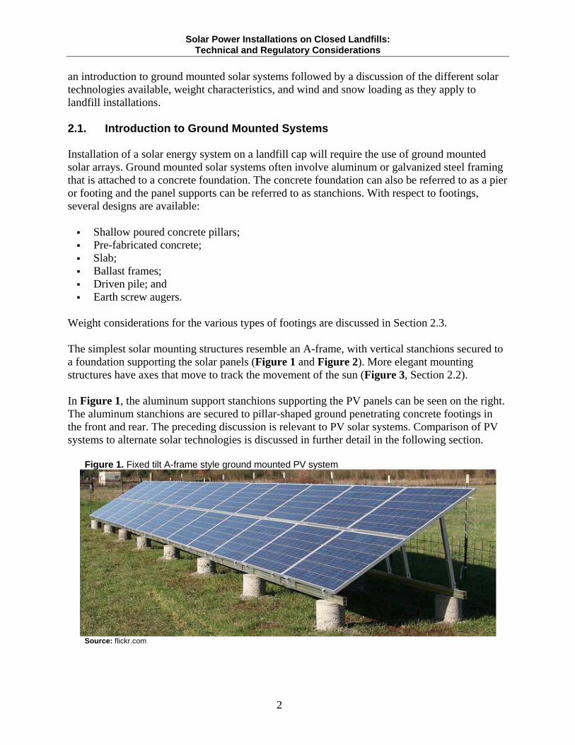
2.2. Different Solar Technologies Generally speaking, most large-scale solar developments have employed the use of PV systems. PV solar energy systems have a number of different attributes that are relevant to installations on landfill caps, including energy output ratings and weight characteristics of the different cell types and support components available. Both fixed tilt and single and double axis sun-tracking mounting structures are available for PV ground installations. Fixed tilt mounting structures consist of panels installed at a permanent angle that maximizes receipt of solar radiation throughout the year, based on the site’s latitude (Figure 1 and Figure 2).
Figure 2. Fixed tilt PV solar array at Fort Carson, CO
Source: flickr.com
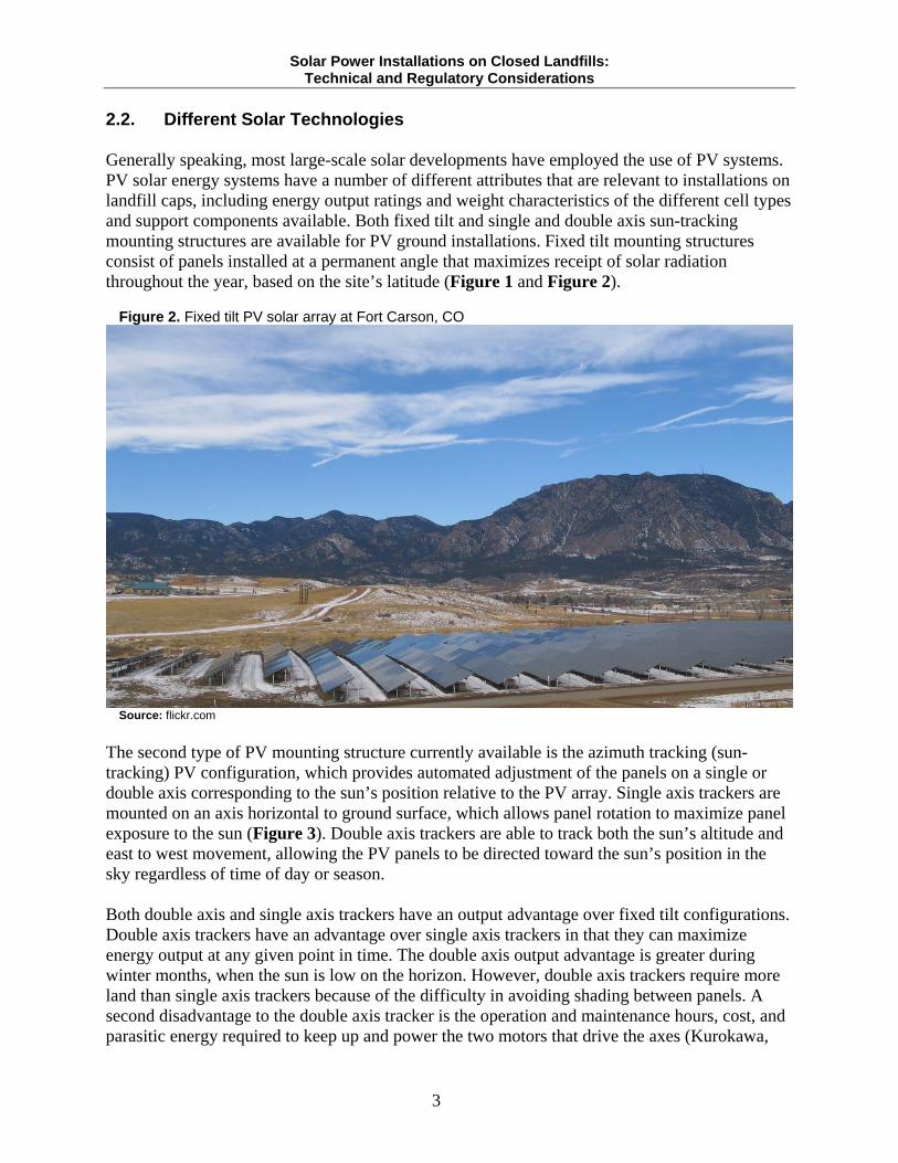
The second type of PV mounting structure currently available is the azimuth tracking (sun-tracking) PV configuration, which provides automated adjustment of the panels on a single or double axis corresponding to the sun’s position relative to the PV array. Single axis trackers are mounted on an axis horizontal to ground surface, which allows panel rotation to maximize panel exposure to the sun (Figure 3). Double axis trackers are able to track both the sun’s altitude and east to west movement, allowing the PV panels to be directed toward the sun’s position in the sky regardless of time of day or season. Both double axis and single axis trackers have an output advantage over fixed tilt configurations. Double axis trackers have an advantage over single axis trackers in that they can maximize energy output at any given point in time. The double axis output advantage is greater during winter months, when the sun is low on the horizon. However, double axis trackers require more land than single axis trackers because of the difficulty in avoiding shading between panels. A second disadvantage to the double axis tracker is the operation and maintenance hours, cost, and parasitic energy required to keep up and power the two motors that drive the axes (Kurokawa,
Solar Power Installations on Closed Landfills: Technical and Regulatory Considerations
4
2003). The disadvantages in the amount of land and operation and maintenance hours required for sun-tracking systems could complicate their application on landfill caps.
Figure 3. Single axis sun-tracking mounting structure, concrete footings, support beams, and PV panels at Nellis Air Force Base, NV
Source: flickr.com
CSP systems have different attributes than PV systems but also have the potential to be used on closed landfill sites. In general terms, CSP technologies use mirrors and reflectors to concentrate and collect solar energy in the form of heat that is transferred through fluids contained in a closed-loop network of receiving tubes and then converted to extremely high temperatures for electricity production. Three main technology systems for CSP are in use today:
1. Linear concentrator systems; 2. Power tower systems; and 3. Dish/Engine systems.
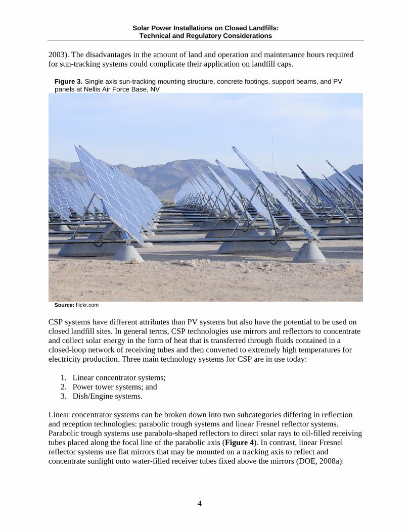
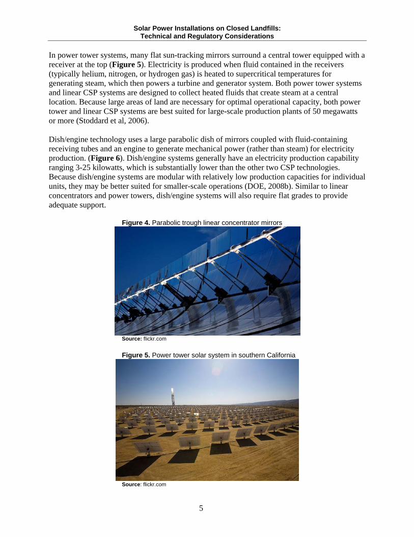
Linear concentrator systems can be broken down into two subcategories differing in reflection and reception technologies: parabolic trough systems and linear Fresnel reflector systems. Parabolic trough systems use parabola-shaped reflectors to direct solar rays to oil-filled receiving tubes placed along the focal line of the parabolic axis (Figure 4). In contrast, linear Fresnel reflector systems use flat mirrors that may be mounted on a tracking axis to reflect and concentrate sunlight onto water-filled receiver tubes fixed above the mirrors (DOE, 2008a).
Solar Power Installations on Closed Landfills: Technical and Regulatory Considerations
5
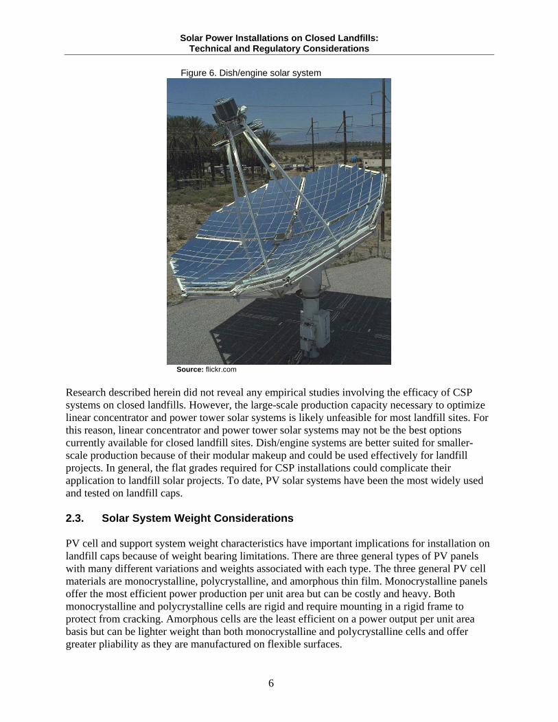
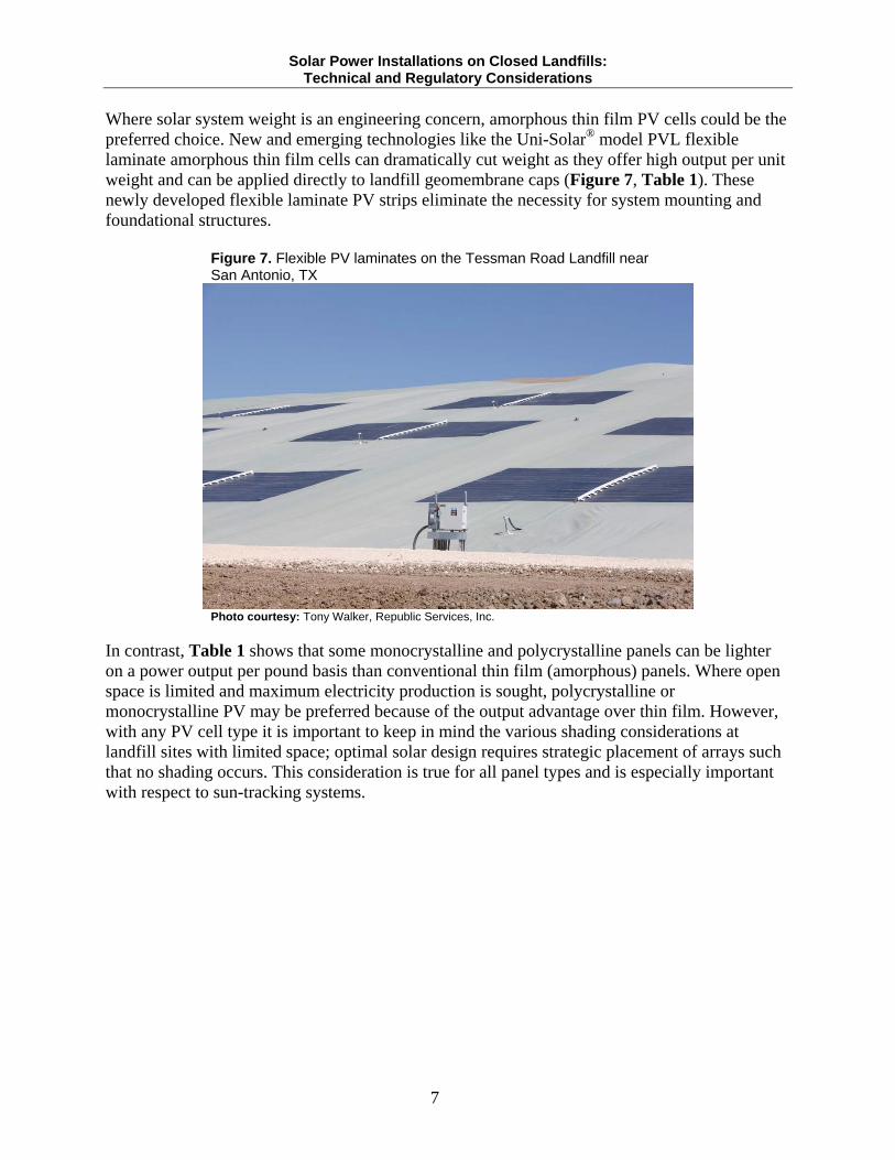
In power tower systems, many flat sun-tracking mirrors surround a central tower equipped with a receiver at the top (Figure 5). Electricity is produced when fluid contained in the receivers (typically helium, nitrogen, or hydrogen gas) is heated to supercritical temperatures for generating steam, which then powers a turbine and generator system. Both power tower systems and linear CSP systems are designed to collect heated fluids that create steam at a central location. Because large areas of land are necessary for optimal operational capacity, both power tower and linear CSP systems are best suited for large-scale production plants of 50 megawatts or more (Stoddard et al, 2006). Dish/engine technology uses a large parabolic dish of mirrors coupled with fluid-containing receiving tubes and an engine to generate mechanical power (rather than steam) for electricity production. (Figure 6). Dish/engine systems generally have an electricity production capability ranging 3-25 kilowatts, which is substantially lower than the other two CSP technologies. Because dish/engine systems are modular with relatively low production capacities for individual units, they may be better suited for smaller-scale operations (DOE, 2008b). Similar to linear concentrators and power towers, dish/engine systems will also require flat grades to provide adequate support. Figure 4. Parabolic trough linear concentrator mirrors
Source: flickr.com
Figure 5. Power tower solar system in southern California
Source: flickr.com
Solar Power Installations on Closed Landfills: Technical and Regulatory Considerations
6
Figure 6. Dish/engine solar system
Source: flickr.com
Research described herein did not reveal any empirical studies involving the efficacy of CSP systems on closed landfills. However, the large-scale production capacity necessary to optimize linear concentrator and power tower solar systems is likely unfeasible for most landfill sites. For this reason, linear concentrator and power tower solar systems may not be the best options currently available for closed landfill sites. Dish/engine systems are better suited for smaller-scale production because of their modular makeup and could be used effectively for landfill projects. In general, the flat grades required for CSP installations could complicate their application to landfill solar projects. To date, PV solar systems have been the most widely used and tested on landfill caps. 2.3. Solar System Weight Considerations PV cell and support system weight characteristics have important implications for installation on landfill caps because of weight bearing limitations. There are three general types of PV panels with many different variations and weights associated with each type. The three general PV cell materials are monocrystalline, polycrystalline, and amorphous thin film. Monocrystalline panels offer the most efficient power production per unit area but can be costly and heavy. Both monocrystalline and polycrystalline cells are rigid and require mounting in a rigid frame to protect from cracking. Amorphous cells are the least efficient on a power output per unit area basis but can be lighter weight than both monocrystalline and polycrystalline cells and offer greater pliability as they are manufactured on flexible surfaces.
Solar Power Installations on Closed Landfills: Technical and Regulatory Considerations
7
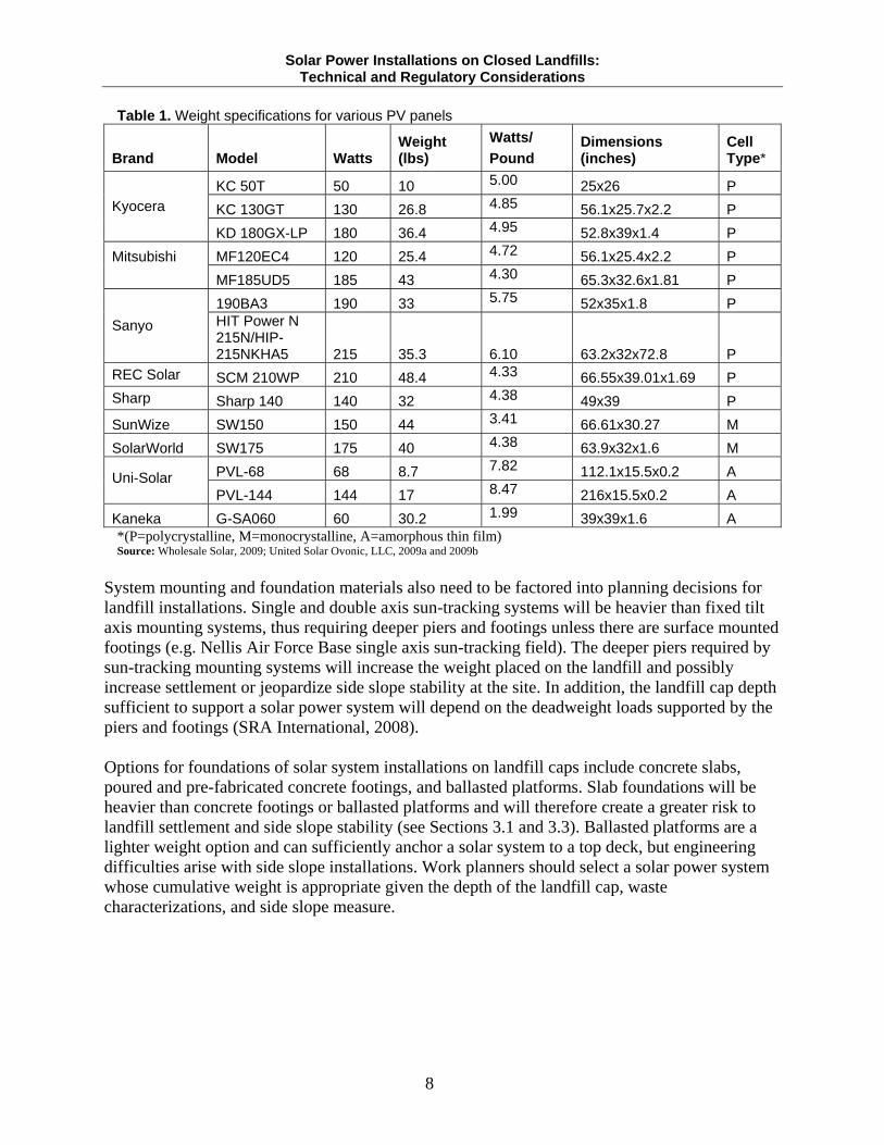
Where solar system weight is an engineering concern, amorphous thin film PV cells could be the preferred choice. New and emerging technologies like the Uni-Solar® model PVL flexible laminate amorphous thin film cells can dramatically cut weight as they offer high output per unit weight and can be applied directly to landfill geomembrane caps (Figure 7, Table 1). These newly developed flexible laminate PV strips eliminate the necessity for system mounting and foundational structures. Figure 7. Flexible PV laminates on the Tessman Road Landfill near San Antonio, TX
Photo courtesy: Tony Walker, Republic Services, Inc.
In contrast, Table 1 shows that some monocrystalline and polycrystalline panels can be lighter on a power output per pound basis than conventional thin film (amorphous) panels. Where open space is limited and maximum electricity production is sought, polycrystalline or monocrystalline PV may be preferred because of the output advantage over thin film. However, with any PV cell type it is important to keep in mind the various shading considerations at landfill sites with limited space; optimal solar design requires strategic placement of arrays such that no shading occurs. This consideration is true for all panel types and is especially important with respect to sun-tracking systems.
Solar Power Installations on Closed Landfills: Technical and Regulatory Considerations
8
Table 1. Weight specifications for various PV panels
Brand Model Watts Weight (lbs)
Watts/
Pound Dimensions (inches)
Cell Type*
KC 50T 50 10 5.00 25x26 P
KC 130GT 130 26.8 4.85 56.1x25.7x2.2 P Kyocera
KD 180GX-LP 180 36.4 4.95 52.8x39x1.4 P
MF120EC4 120 25.4 4.72 56.1x25.4x2.2 P Mitsubishi MF185UD5 185 43 4.30 65.3x32.6x1.81 P
190BA3 190 33 5.75 52x35x1.8 P
Sanyo HIT Power N 215N/HIP-215NKHA5 215 35.3
6.10 63.2x32x72.8 P
REC Solar SCM 210WP 210 48.4 4.33 66.55x39.01x1.69 P
Sharp Sharp 140 140 32 4.38 49x39 P
SunWize SW150 150 44 3.41 66.61x30.27 M
SolarWorld SW175 175 40 4.38 63.9x32x1.6 M
PVL-68 68 8.7 7.82 112.1x15.5x0.2 A Uni-Solar PVL-144 144 17 8.47 216x15.5x0.2 A
Kaneka G-SA060 60 30.2 1.99 39x39x1.6 A *(P=polycrystalline, M=monocrystalline, A=amorphous thin film) Source: Wholesale Solar, 2009; United Solar Ovonic, LLC, 2009a and 2009b
System mounting and foundation materials also need to be factored into planning decisions for landfill installations. Single and double axis sun-tracking systems will be heavier than fixed tilt axis mounting systems, thus requiring deeper piers and footings unless there are surface mounted footings (e.g. Nellis Air Force Base single axis sun-tracking field). The deeper piers required by sun-tracking mounting systems will increase the weight placed on the landfill and possibly increase settlement or jeopardize side slope stability at the site. In addition, the landfill cap depth sufficient to support a solar power system will depend on the deadweight loads supported by the piers and footings (SRA International, 2008). Options for foundations of solar system installations on landfill caps include concrete slabs, poured and pre-fabricated concrete footings, and ballasted platforms. Slab foundations will be heavier than concrete footings or ballasted platforms and will therefore create a greater risk to landfill settlement and side slope stability (see Sections 3.1 and 3.3). Ballasted platforms are a lighter weight option and can sufficiently anchor a solar system to a top deck, but engineering difficulties arise with side slope installations. Work planners should select a solar power system whose cumulative weight is appropriate given the depth of the landfill cap, waste characterizations, and side slope measure.
Solar Power Installations on Closed Landfills: Technical and Regulatory Considerations
9
2.4. Wind Loading and Snow Loading Wind and snow accumulation increase the weight placed on solar components and can increase the stress applied to the support structures. The International Electrotechnical Commission (IEC) standards 61215 and 61646 establish the industry standards for crystalline cell and amorphous thin cell mechanical loading, respectively. Customary solar panels are typically certified to withstand a maximum mechanical loading of 50 pounds per square foot, which converts to a wind speed of approximately 105 miles per hour. However, landfill sites that are located in areas prone to high winds or snow may need to consider the use of solar panels and mounting systems that are certified for higher mechanical loading. Also, work planners should consider routine operations and maintenance of the landfill cover when purchasing solar panel and mounting configurations. Some landfills may require routine mowing of surface vegetation on the cap. Consequently, the solar panel and mounting configurations may need to be stationed high enough to allow a mowing tractor to drive underneath. Placement of panels this high will increase the weight and stress of the configuration by virtue of the longer pier lengths and increased wind loading. The second thing to consider is the added weight of snow accumulation on solar panels in colder regions. Snow loading is more of a concern for systems installed on landfill side slopes because the added weight of accumulated snow or ice will increase the pressure placed on the foundations anchoring the solar system to the landfill. These wind and snow loading considerations should be taken into account early in the planning stage (Ali, Samina). 3. TECHNICAL CHALLENGES Installation of solar energy systems on landfill side slopes and caps is complicated by a variety of engineering obstacles. This section provides background information and general guidance on some of the most common engineering obstacles of landfill reuse as they apply to solar system installations. A closing summary provides case evidence supporting potential remedies to the technical challenges. 3.1. Settlement A special consideration when designing a solar installation on a landfill cap is settlement – the collective uniform and non-uniform landfill deformations caused by physiochemical, biochemical, and mechanical processes that change properties of the buried waste over time. Total settlement is described as an overall subsidence across the landfill. Differential settlement is described as localized subsidence that results from heterogeneities across waste debris in the landfill. Specifically, settlement can occur in landfills through any of five processes:
1. Mechanical consolidation; 2. Biochemical degradation; 3. Physiochemical change; 4. Migration of fine refuse into the voids of large waste materials (raveling); and/or 5. Any combination of 1-4 above (Christensen et al, 1994).
Solar Power Installations on Closed Landfills: Technical and Regulatory Considerations
10
The absolute degree of active settlement depends on the depth of the waste heap, the type of waste present, the method of placement, and age of the landfill (Walsh et al, date unknown). In terms of geotechnical engineering, differential settlement is commonly more problematic to the integrity of structures placed on landfill covers (caps) than total settlement. Over time, a closed landfill could be affected by surface cracks in the final cover, damage to the water drainage system, damage to leachate and gas collection piping, formation of water-holding depressions, and damage to underground utilities (El-Fadel et al, 2000). Differential settlement within the landfill is a particular risk to array piers, footings, and electrical lines and can disrupt the position of solar panels in relation to the sun. Consequently, differential settlement poses a substantial, yet common, engineering problem to both the long-term post closure care of the landfill and the system components of a solar energy farm. Immediate settlement occurs from the rapid mechanical compression of buried waste debris. Solar array construction or the use of heavy equipment for clearing and grading activities on the cap could elicit immediate settlement. Any activities carried out by construction parties must safeguard against provoking immediate settlement and affiliated impacts on a landfill cap. Settlement safeguards may include controlling construction traffic above the landfill, or using engineering methods to spread weight more equitably over the cap. More gradual long-term settlement over the life of the project should also be taken into consideration during the planning phase and solar system materials should be designed accordingly. Rates of settlement can be estimated using work experience, modeling, or observation. Data collected from background investigations can reveal the age and depth of waste as well as the type of waste present and the placement methods used when the landfill was in operation. All are important in estimating past and expected active settlement. In cases where settlement is a concern, it is unfavorable to place a single or double axis sun-tracking solar system as settlement may disrupt the angle of the tracking system and result in inefficient solar output. The impacts of settlement on a fixed axis solar system are typically nominal, except in the most severe instances where the angle of the solar array is significantly disrupted away from the latitude of the site. In all cases, the support footings and stanchions of the solar system should be flexible enough to adjust to any changes in elevation that might occur as a result of settlement (Chern, Shiann-Jang). In addition, extreme deadweight loading events can activate or exacerbate immediate settlement. For instance, placing a heavy concrete slab foundation on a landfill could compact the underlying waste and the resulting landscape shifts could ultimately damage the concrete foundation. Large concrete slab foundations are also more vulnerable to cracking from incidental settlement. For these reasons, it may be safer to use shallow concrete footings or ballasts as foundation for the solar arrays. Weight of the solar array should also be considered with regards to potential landfill settlement (see Section 2.3). Solar technologies vary greatly in terms of weight of the solar panels and mounting structures. Work planners should design the solar energy system to be flexible enough
Solar Power Installations on Closed Landfills: Technical and Regulatory Considerations
11
to account for the impacts that a solar energy facility will have on the landfill settlement and vice versa. There are numerous engineering measures that can be used to reduce the potential for landfill settlement. For instance, dynamic compaction is the practice of controlled tamping of loose soils to promote densification. Dynamic compaction has been shown to increase material density and decrease differential settlement in MSW landfills (Van Impe et al, 1996). Selective waste removal and replacement with clean fill can also enhance landfill densification. These procedures are best practiced prior to landfill closure and are viable strategies for simultaneous landfill closure and development projects. For developments on landfills that have been previously closed, there are numerous methods to mitigate settlement. Geogrid reinforcement can be used to strengthen the cover soils above the geomembrane. Beyond structural reinforcement, designed flexibility in the solar system can preclude damages to the solar configuration caused by settlement. The use of shims and adjustable racking systems in solar mounting structures can allow for amending the solar system in ways that conform to landscape morphology. Being selective in where solar energy systems are placed on a landfill can minimize settlement impacts. One strategy is to place the solar facility on the oldest section of the landfill top deck, since the rates of settlement generally decrease over time. Another strategy examines the nature of different buried materials; for example, a solar system placed above old construction debris that has been previously compacted will not experience significant settlement because of low biochemical degradation (Messics, 2009). Table 2 in Section 3.5 provides a summary of settlement complications and potential remedies.
3.2. Cover Material Integrity For the most part, either a flat or north-to-south trending slope is optimal for solar energy production in the United States, depending on latitudinal location. When preparing a landfill site for construction of a solar energy facility, it may be necessary to clear and grade the landfill cap surface in order to gain open space for the solar arrays and prevent possible shade effects. Clearing and grading activities should be done in a way that does not damage the landfill cap or expose any of the underlying waste debris, particularly when conducted in thinly capped areas. In circumstances where the site is deeply vegetated, heavy mechanical thinning of vegetation may be necessary. During the planning process, the depth of the landfill cover should be determined to confirm that it can carry the anticipated deadweight loading of the entire solar energy system. Certain solar system manufacturers recommend level surfaces for adequate system stability, which may necessitate moving soil from deeper areas to shallower areas or bringing additional top soil to the site. In almost all cases, prefabricated concrete piers or concrete slabs will be adequate to support a solar system; for a relatively low impact development like a solar farm, cap-penetrating pilings will be superfluous and costly in terms of permitting and capital expenses.
Solar Power Installations on Closed Landfills: Technical and Regulatory Considerations
12
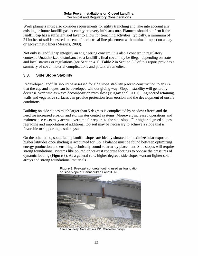
Work planners must also consider requirements for utility trenching and take into account any existing or future landfill gas-to-energy recovery infrastructure. Planners should confirm if the landfill cap has a sufficient soil layer to allow for trenching activities; typically, a minimum of 24 inches of soil is desired to trench for electrical line placement with minimal impact on a clay or geosynthetic liner (Messics, 2009). Not only is landfill cap integrity an engineering concern, it is also a concern in regulatory contexts. Unauthorized disturbance to a landfill’s final cover may be illegal depending on state and local statutes or regulations (see Section 4.1). Table 2 in Section 3.5 of this report provides a summary of cover material complications and potential remedies. 3.3. Side Slope Stability Redeveloped landfills should be assessed for side slope stability prior to construction to ensure that the cap and slopes can be developed without giving way. Slope instability will generally decrease over time as waste decomposition rates slow (Misgav et al, 2001). Engineered retaining walls and vegetative surfaces can provide protection from erosion and the development of unsafe conditions. Building on side slopes much larger than 5 degrees is complicated by shadow effects and the need for increased erosion and stormwater control systems. Moreover, increased operations and maintenance costs may accrue over time for repairs to the side slope. For higher degreed slopes, regrading and importation of additional top soil may be necessary to achieve a slope that is favorable to supporting a solar system. On the other hand, south facing landfill slopes are ideally situated to maximize solar exposure in higher latitudes once shading is accounted for. So, a balance must be found between optimizing energy production and ensuring technically sound solar array placement. Side slopes will require strong foundational systems like poured or pre-cast concrete footings to oppose the pressures of dynamic loading (Figure 8). As a general rule, higher degreed side slopes warrant lighter solar arrays and strong foundational materials.
Figure 8. Pre-cast concrete footing used as foundation on side slope at Pennsauken Landfill, NJ
Photo courtesy: Mark Messics, PPL Renewable Energy
Solar Power Installations on Closed Landfills: Technical and Regulatory Considerations
13
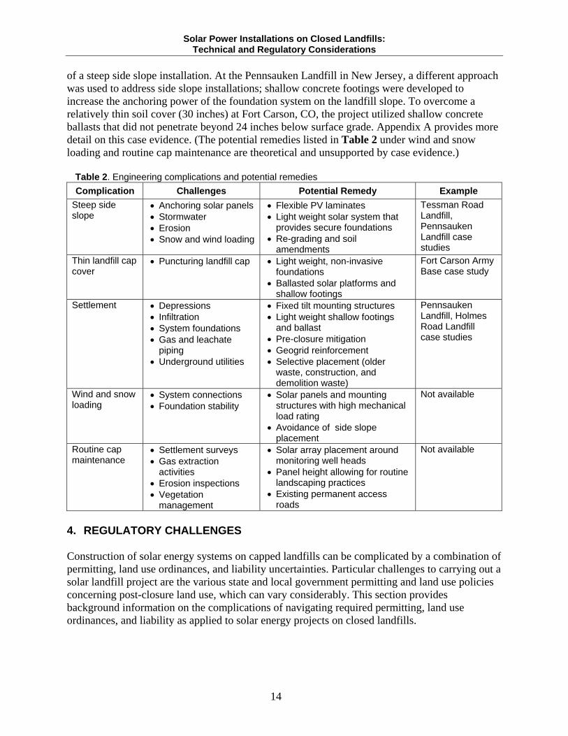
Another factor to consider when planning placement of solar arrays on a side slope is snow and ice loading. The accumulation of snow and ice on solar system components will increase the weight of the system and therefore increase the gravitational force placed on the system foundation. Work planners must choose solar panels with appropriate mechanical load ratings and foundation systems with adequate strength when building on side slopes. For example, a PV solar system on an 18-degree (3:1) side slope was successfully installed at the Tessman Road Landfill in Texas (see Appendix A). The project used extremely light weight flexible solar laminates that adhered directly to the geomembrane cover. Because the solar laminates were low in weight and fixed directly to the cap, there was no risk in having the system slide off the slope. Table 2 in Section 3.5 of this report provides a summary of side slope installation challenges and potential remedies. 3.4. Renewable Energy Production on Superfund or Brownfield Sites Cleanup at many Superfund or brownfield sites involves a remedy calling for installation of a cap over uncontrolled landfills or safeguards for existing landfill caps. Design engineers for solar power farms at these sites need to recognize that all aspects of the facility (including construction, operations and maintenance, and eventual deconstruction) must be conducted in a way that ensures no adverse impacts on the site’s cleanup remedy(s). For example, how the solar system will interact with routine landfill settlement surveys, landfill gas surveys, gas extraction activities, erosion inspections, and routine cap maintenance should be considered during the design and planning phase (Chern, Shiann-Jang). An example previously mentioned was the consideration of PV panel height, pier depth, and stanchion length with respect to routine cap vegetation management (Section 2.4). Onsite construction traffic for placement of the solar power system foundation and components should be minimized wherever feasible in the interest of avoiding deadweight loading events and damage to the landfill cap. When it is necessary to traverse the landfill cap, temporary roadway surfaces should be used to minimize localized compaction and overall soil disturbance. Any eroded landfill surfaces that result from construction activities should be remedied immediately to prevent exacerbation of further erosion in accordance with local permitting requirements (Section 4.1). Beyond the need for temporary roadway surfaces, a more permanent access road may need to be constructed to facilitate solar system operations and maintenance activities. The presence or absence of existing access roads, including accessibility to the top deck of a landfill cover, should be a factor when considering sites for development. 3.5. Summary of Technical Complications, Challenges, and Potential Remedies Table 2 summarizes some of the engineering complications previously discussed and identifies potential remedies. Case evidence is provided by four projects. The Tessman Road Landfill project involved installation on an 18-degree side slope utilizing flexible PV laminates that were fixed directly to the exposed geomembrane. Use of an alternative cover design with the flexible laminates allowed the Tessman Road project to overcome some of the engineering complications
Solar Power Installations on Closed Landfills: Technical and Regulatory Considerations
14
of a steep side slope installation. At the Pennsauken Landfill in New Jersey, a different approach was used to address side slope installations; shallow concrete footings were developed to increase the anchoring power of the foundation system on the landfill slope. To overcome a relatively thin soil cover (30 inches) at Fort Carson, CO, the project utilized shallow concrete ballasts that did not penetrate beyond 24 inches below surface grade. Appendix A provides more detail on this case evidence. (The potential remedies listed in Table 2 under wind and snow loading and routine cap maintenance are theoretical and unsupported by case evidence.)
Table 2. Engineering complications and potential remedies
Complication Challenges Potential Remedy Example
Steep side slope
Anchoring solar panels Stormwater Erosion Snow and wind loading
Flexible PV laminates Light weight solar system that
provides secure foundations Re-grading and soil
amendments
Tessman Road Landfill, Pennsauken Landfill case studies
Thin landfill cap cover
Puncturing landfill cap Light weight, non-invasive foundations
Ballasted solar platforms and shallow footings
Fort Carson Army Base case study
Settlement Depressions Infiltration System foundations Gas and leachate
piping Underground utilities
Fixed tilt mounting structures Light weight shallow footings
and ballast Pre-closure mitigation Geogrid reinforcement Selective placement (older
waste, construction, and demolition waste)
Pennsauken Landfill, Holmes Road Landfill case studies
Wind and snow loading
System connections Foundation stability
Solar panels and mounting structures with high mechanical load rating
Avoidance of side slope placement
Not available
Routine cap maintenance
Settlement surveys Gas extraction
activities Erosion inspections Vegetation
management
Solar array placement around monitoring well heads
Panel height allowing for routine landscaping practices
Existing permanent access roads
Not available
4. REGULATORY CHALLENGES Construction of solar energy systems on capped landfills can be complicated by a combination of permitting, land use ordinances, and liability uncertainties. Particular challenges to carrying out a solar landfill project are the various state and local government permitting and land use policies concerning post-closure land use, which can vary considerably. This section provides background information on the complications of navigating required permitting, land use ordinances, and liability as applied to solar energy projects on closed landfills.
Solar Power Installations on Closed Landfills: Technical and Regulatory Considerations
15
4.1. Required Permitting Most landfills are subject to regulations under Subtitle D of the Resource Conservation and Recovery Act (RCRA). Subtitle D of RCRA regulates: Municipal solid waste; Household hazardous waste; Municipal sludge; Nonhazardous industrial wastes; Municipal combustion ash; Small quantity generator’s hazardous waste; Construction and demolition debris; Agriculture waste; Oil and gas waste; and Mining waste.
State and local governments are responsible for the primary planning, permitting, regulation, implementation, and enforcement of RCRA Subtitle D waste. Accordingly, the permit requirements for post-closure landfill use (such as solar farm development) will vary from state to state. Work planners must always check with the appropriate local environmental agency to determine which post-closure use permits, environmental policies, and local ordinances (zoning, building, wetlands, etc) are relevant to the project. A 2008 survey of all 50 states revealed that 13 states had no ordinances against landfill development. The remaining 37 states did not respond to the survey. Many of the respondent states dealt with landfill development through post-closure plans, including Alaska, Florida, Illinois, Massachusetts, Ohio, Oregon, Utah, and Washington. California reviews landfill development proposals through their California Environmental Quality Act process and Rhode Island has a Landfill Cleanup Program that oversees redevelopment. The three remaining respondent states, New Jersey, Texas, Wisconsin, had specific permit processes for landfill development (Masson, 2008). Some states require obtainment of a closure permit if the landfill in question had not been closed or capped in accordance with environmental departmental requirements or if the landfill had been capped or closed prior to a specific date. In these cases, a closure permit would need to be obtained prior to applying for a post-closure use permit. Local ordinances may be more restrictive (Section 4.2). Some states have two or more types of post-closure permits, depending on the reuse activity and level of disturbance to the landfill. For example, Massachusetts has two types of post-closure use permits, classified as “Major” and “Minor”. “Minor” permits are required for passive developments that do not necessitate construction or installation of structures into or onto the landfill cap. “Major” permits are required for projects involving construction and installation of structures. Under Massachusetts’s post-closure permitting program, all solar projects that would involve construction of footings onto the landfill cap or physical alteration of the cap in any way
Solar Power Installations on Closed Landfills: Technical and Regulatory Considerations
16
would require a “Major” post-closure permit (Massachusetts Department of Environmental Protection, 2009). In the case of the state of Massachusetts, the following materials must be submitted in support of the post-closure use permit:
1. Solid waste site assignment; 2. Landfill property deed; 3. Environmental site assessment; 4. Closure permit and certification; 5. Site plan; 6. Landfill capping design plan; 7. Post-closure use design plan; 8. Storm water drainage/run-off control plan; 9. Storm water erosion control plan; 10. Landfill gas control and monitoring plan; 11. Geotechnical stability and settlement analysis; 12. Capping system interface; 13. Utilities description; 14. Environmental monitoring description; 15. Qualitative health and environmental risk assessment; 16. Post-closure monitoring and maintenance plan; 17. Financial assurance; 18. Wetlands protection plan; 19. Documentation that the site is in compliance with state environmental protection statutes
(Massachusetts Department of Environmental Protection, 2009). California closely regulates any construction activities on closed landfills, with particular concern over the continued integrity of a landfill cover. Title 27 of the California Code of Regulations addressing post-closure landfill use states: “Construction on the site shall maintain the integrity of the final cover, drainage and erosion control systems, and gas monitoring and control systems. The owner or operator shall demonstrate to the satisfaction of the EA [expenditure account] that the activities will not pose a threat to public health and safety and the environment. Any proposed modification or replacement of the low permeability layer of the final cover shall begin upon approval by the EA, and the RWQCB [Regional Water Quality Control Board] (California Code of Regulations, 2009a).” Title 27 also stipulates that pilings cannot be installed into or through the final landfill layer without permission of the RWQCB. If permission is granted by RWQCB, then the responsible party must replace or repair the low permeability layer (California Code of Regulations, 2009b). Other states have less stringent permitting requirements. For instance, the Texas Commission on Environmental Quality (TCEQ) requires post-closure permits only for enclosed structures. However, any activity or development that would disturb the final cover must have prior written
Solar Power Installations on Closed Landfills: Technical and Regulatory Considerations
17
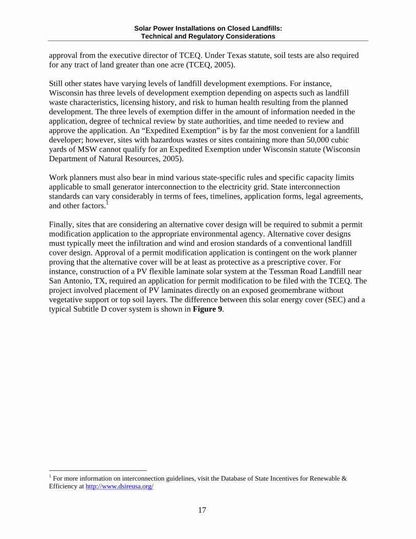
approval from the executive director of TCEQ. Under Texas statute, soil tests are also required for any tract of land greater than one acre (TCEQ, 2005). Still other states have varying levels of landfill development exemptions. For instance, Wisconsin has three levels of development exemption depending on aspects such as landfill waste characteristics, licensing history, and risk to human health resulting from the planned development. The three levels of exemption differ in the amount of information needed in the application, degree of technical review by state authorities, and time needed to review and approve the application. An “Expedited Exemption” is by far the most convenient for a landfill developer; however, sites with hazardous wastes or sites containing more than 50,000 cubic yards of MSW cannot qualify for an Expedited Exemption under Wisconsin statute (Wisconsin Department of Natural Resources, 2005). Work planners must also bear in mind various state-specific rules and specific capacity limits applicable to small generator interconnection to the electricity grid. State interconnection standards can vary considerably in terms of fees, timelines, application forms, legal agreements, and other factors.1 Finally, sites that are considering an alternative cover design will be required to submit a permit modification application to the appropriate environmental agency. Alternative cover designs must typically meet the infiltration and wind and erosion standards of a conventional landfill cover design. Approval of a permit modification application is contingent on the work planner proving that the alternative cover will be at least as protective as a prescriptive cover. For instance, construction of a PV flexible laminate solar system at the Tessman Road Landfill near San Antonio, TX, required an application for permit modification to be filed with the TCEQ. The project involved placement of PV laminates directly on an exposed geomembrane without vegetative support or top soil layers. The difference between this solar energy cover (SEC) and a typical Subtitle D cover system is shown in Figure 9.
1 For more information on interconnection guidelines, visit the Database of State Incentives for Renewable & Efficiency at http://www.dsireusa.org/
Solar Power Installations on Closed Landfills: Technical and Regulatory Considerations
18
Figure 9. SEC system (left) compared to a typical RCRA Subtitle D cover system (right)
Source: Roberts et al, 2008
4.2. Zoning and Land Use It is important to point out that some local government ordinances may prohibit the development of disposal sites altogether. Other state and local ordinances only allow limited land use of closed landfills. For example, the Minnesota Pollution Control Agency (MPCA) owns 25 of 112 landfills under the state’s Closed Landfill Program (CLP). The remaining 87 closed landfills are either privately owned or owned by local governments. Even so, the MPCA has the right to limit land uses on all closed landfills through legally binding agreements, easements, and restrictive covenants (MPCA, 2008). In these cases, work planners would have to contact the MPCA or equivalent local environmental agencies to determine if land use restrictions apply to their site. When disposal site development is not prohibited, it is the responsibility of the work planner to notify the planning department and local enforcement agency of a change in land use. For example, Title 27, Section 21190, Subparagraph (c) of the California Code of Regulations requires that:
“All proposed post-closure land uses, other than non-irrigated open space, on sites implementing closure or on closed sites shall be submitted to the EA, RWQCB, local air district and local land use agency. The EA shall review and approve proposed post-closure land uses if the project involves structures within 1,000 feet of the disposal area, structures on top of waste, modification of the low permeability layer, or irrigation over waste” (California Code of Regulations, 2009c) 4.3. Existing Contamination and Environmental Site Investigations In many instances an environmental site investigation (ESI) is a required component of a landfill post-closure use application. Environmental site investigations are used to delineate boundaries, identify waste types, reveal any soil and groundwater contamination on site, and characterize
Solar Power Installations on Closed Landfills: Technical and Regulatory Considerations
19
other site aspects. The following activities and considerations are true for almost any post-closure landfill development and pose liability implications for onsite solar energy system development (Section 4.4). In some cases, a previously completed ESI can be used to fulfill the post closure development application. For instance, an ESI was conducted at the Holmes Road Landfill by Terracon in 2006. As a result, current solar development of the landfill can proceed with reliance on the previously conducted ESI (SRA International, 2008). Work planners should check with their local environmental regulator to determine if a previously conducted ESI can be used when submitting a post-closure development application. Regardless of whether a new ESI is required, an inspection should be made to determine locations of landfill gas vents and monitoring well heads to confirm if they are accurately marked on a site plan. Confirming the location of landfill gas vents and well heads will protect against any damage to a landfill cover during construction activities and can facilitate placement of the solar system components (Ali, undated). It is also valuable to point out that landfill sites where remedial action has taken place under the Comprehensive Environmental Response, Compensation, and Liability Act (CERCLA) will be subject to the five-year review process. Therefore, it is important to confirm that the solar energy system does not interfere with performance of the site’s cleanup remedy. 4.4. CERCLA Liability Many closed landfills under consideration for commercial-scale renewable energy development are located on brownfields or Superfund sites that have been cleaned up or are undergoing cleanup, and are thus subject to CERCLA requirements. From a legal and investment perspective, a substantial consideration for developing Superfund or brownfield sites is the adverse impacts of potential liability under CERCLA. However, changes were made to CERCLA in 2002 in the form of the Small Business Liability Relief and Brownfields Revitalization Act (“Brownfields Law”) to address the potential CERCLA liability of a property transfer. Parties protected from CERCLA liability under the Brownfields Law include innocent landowners, contiguous property owners, bona fide prospective purchasers, and units of state or local governments that acquire property through bankruptcy, tax delinquency, or abandonment. Under Section 222 of the Brownfields Law, prospective property owners may receive liability protections under the following conditions:
1. “All disposal of hazardous substances at the facility occurred before the person acquired the facility;
2. The person made all appropriate inquiries into the previous ownership and uses of the facility;
3. The person provides all legally required notices with respect to the discovery or release of any hazardous substances at the facility;
4. The person exercises appropriate care with respect to hazardous substances found at the facility by taking reasonable steps to--
a. Stop any continuing release;
Solar Power Installations on Closed Landfills: Technical and Regulatory Considerations
20
b. Prevent any threatened future release; c. Prevent or limit human, environmental, or natural resource exposure to any
previously released hazardous substance 5. The person provides full cooperation, assistance, and access to persons that are
authorized to conduct response actions or natural resource restoration at a vessel or facility;
6. Is in compliance with any land use restrictions established or relied on in connection with the response action at a vessel or facility and does not impede the effectiveness or integrity of any institutional control employed at the vessel or facility in connection with a response action;
7. The person complies with any request for information or administrative subpoena issued by the President under this Act;
8. The person is not-- a. Potentially liable, or affiliated with any other person that is potentially liable, for
response costs at a facility through-- i. Any direct or indirect familial relationship; or ii. Any contractual, corporate, or financial relationship
b. The result of a reorganization of a business entity that was potentially liable” The U.S. EPA offers several tools to address landowner liability concerns, including:
1. Comfort/status letters; 2. Prospective purchaser agreements (PPA) and prospective lease agreements (PLA); 3. Bona fide prospective purchaser (BFPP) work agreements; and 4. Windfall lien resolution agreements
Comfort/status letters can be provided to help interested parties better understand EPA’s involvement in a potentially contaminated site. A comfort/status letter can address: Likelihood of EPA involvement in a property; Specific statutory provisions or EPA policies that may be applicable; The cleanup process; and Steps that should be taken at a site (EPA, 2009)
Although PPAs and PLAs became largely obsolete following the 2002 CERLA amendment, EPA will still enter into a PPA under limited circumstances such as cases where substantial environmental benefit exists or a PPA is needed to accomplish project goals (EPA, 2009). BFPP work agreements, which go beyond the protection provided by the Brownfields Law, are designed in particular to address sites where work beyond reasonable steps to stop current release or prevent future release of contaminants is warranted. A windfall lien resolution agreement can be used to “release and waive any windfall lien, arising under Section 107(r) of CERCLA with respect to a bona fide prospective purchaser, through the payment of cash or other appropriate consideration” (EPA, 2003).
Solar Power Installations on Closed Landfills: Technical and Regulatory Considerations
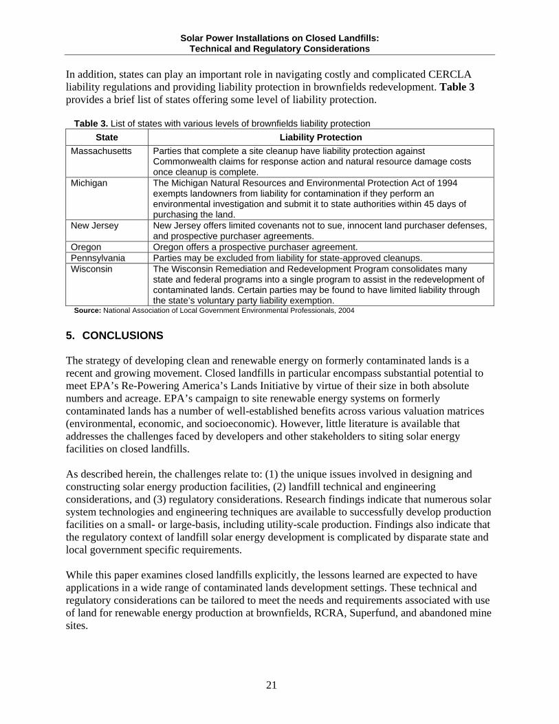
21
In addition, states can play an important role in navigating costly and complicated CERCLA liability regulations and providing liability protection in brownfields redevelopment. Table 3 provides a brief list of states offering some level of liability protection.
Table 3. List of states with various levels of brownfields liability protection
State Liability Protection
Massachusetts Parties that complete a site cleanup have liability protection against Commonwealth claims for response action and natural resource damage costs once cleanup is complete.
Michigan The Michigan Natural Resources and Environmental Protection Act of 1994 exempts landowners from liability for contamination if they perform an environmental investigation and submit it to state authorities within 45 days of purchasing the land.
New Jersey New Jersey offers limited covenants not to sue, innocent land purchaser defenses, and prospective purchaser agreements.
Oregon Oregon offers a prospective purchaser agreement. Pennsylvania Parties may be excluded from liability for state-approved cleanups. Wisconsin The Wisconsin Remediation and Redevelopment Program consolidates many
state and federal programs into a single program to assist in the redevelopment of contaminated lands. Certain parties may be found to have limited liability through the state’s voluntary party liability exemption.
Source: National Association of Local Government Environmental Professionals, 2004
5. CONCLUSIONS The strategy of developing clean and renewable energy on formerly contaminated lands is a recent and growing movement. Closed landfills in particular encompass substantial potential to meet EPA’s Re-Powering America’s Lands Initiative by virtue of their size in both absolute numbers and acreage. EPA’s campaign to site renewable energy systems on formerly contaminated lands has a number of well-established benefits across various valuation matrices (environmental, economic, and socioeconomic). However, little literature is available that addresses the challenges faced by developers and other stakeholders to siting solar energy facilities on closed landfills. As described herein, the challenges relate to: (1) the unique issues involved in designing and constructing solar energy production facilities, (2) landfill technical and engineering considerations, and (3) regulatory considerations. Research findings indicate that numerous solar system technologies and engineering techniques are available to successfully develop production facilities on a small- or large-basis, including utility-scale production. Findings also indicate that the regulatory context of landfill solar energy development is complicated by disparate state and local government specific requirements. While this paper examines closed landfills explicitly, the lessons learned are expected to have applications in a wide range of contaminated lands development settings. These technical and regulatory considerations can be tailored to meet the needs and requirements associated with use of land for renewable energy production at brownfields, RCRA, Superfund, and abandoned mine sites.
Solar Power Installations on Closed Landfills: Technical and Regulatory Considerations
22
6. REFERENCES
1. Ali, Samina, Solar Consultant, Boreal Renewable Energy Development, [email protected]. Personal correspondence.
2. California Environmental Protection Regulations, 2009a. Title 27, Subchapter 5, Article
2, Section 21190, Subparagraph (d), California Code of Regulations. http://www.ciwmb.ca.gov/Regulations/title27/ch3sb5.htm#21190 [Accessed July 21, 2009].
3. California Environmental Protection Regulations, 2009b. Title 27, Subchapter 5, Article
2, Section 21190, Subparagraph (e), California Code of Regulations. http://www.ciwmb.ca.gov/Regulations/title27/ch3sb5.htm#21190 [Accessed July 21, 2009].
4. California Environmental Protection Regulations, 2009c. Title 27, Subchapter 5, Article
2, Section 21190, Subparagraph (c), California Code of Regulations. http://www.ciwmb.ca.gov/Regulations/title27/ch3sb5.htm#21190 [Accessed July 21, 2009].
5. Chern, Shiann-Jang, Ph.D., P.E., Superfund Project Manager, U.S. Environmental
Protection Agency, Region 9, [email protected]. Personal correspondence. 6. Christensen, T.H., Cossu, R., Stegmann, R. Landfilling of Waste: Barriers. London: E &
FN Spon, 1994. 7. El-Fadel, M. and Khoury, R. “Modeling Settlement in MSW Landfills: A Critical
Review.” Critical Reviews in Environmental Science and Technology 30.3 (2000): 327-361.
8. Kurokawa, Kosuke. Energy from the Desert: Feasibility of Very Large Scale
Photovoltaic Power Generation (VLS-PV) Systems. London: James and James Ltd, 2003. 9. Massachusetts Department of Environmental Protection. 2009. “Landfill Post-Closure
Use Permitting Guidelines.” http://www.mass.gov/dep/recycle/laws/policies.htm#lfpcguid [Accessed July 20, 2009].
10. Masson, P.T. 2008. “Should Landfills be Redeveloped: What do Various States Think?”
Presented at 2008 Solid Waste Association of North America – 23rd Annual Northwest Regional Solid Waste Symposium. McMenamins Edgefield, Troutdale, OR. April 17, 2008. http://www.swanaoregon.org/symposium_2008.htm [Accessed July 21, 2009].
11. Messics, Mark. “Site Considerations: What Makes a Site Desirable for a Solar Project?”
Presented at Renewable Energy at Closed Landfill Workshop. Mansfield/Foxboro Holiday Inn, Mansfield, MA. June 17, 2009. http://www.mass.gov/dep/energy/solarsite.pdf [Accessed August 13, 2009].
Solar Power Installations on Closed Landfills: Technical and Regulatory Considerations
23
12. Minnesota Pollution Control Agency. “Closed Landfill Program – Land Use Planning.” September 2008. http://www.pca.state.mn.us/publications/c-clf1-02.pdf [Accessed August 11, 2009].
13. Misgav, A., Perl, N., Avnimelech, Y. “Selecting a Compatible Open Space Use for a
Closed Landfill Site.” Landscape and Urban Planning 55.2 (2001): 95-111. 14. National Association of Local Government Environmental Professionals, Northeast-
Midwest Institute. 2004. “Unlocking Brownfields: Keys to Community Revitalization.” http://www.resourcesaver.com/file/toolmanager/CustomO93C337F65023.pdf [Accessed August 4, 2009].
15. Roberts, M., Perera, K., Alexander, T., Walker, T. “Alternative Landfill Closure: Solar
Energy Cover Systems.” 2008. Engineering design paper provided through personal correspondence with Tony Walker, Republic Services, [email protected].
16. Small Business Liability Relief and Brownfields Revitalization Act of 2001, Section 222,
Pub. L. No. 107-118, H.R. 2869, 107th Congress, 1st Session. 2001. 17. SRA International. 2008. “Solar Power Analysis and Design Specifications: Technical
Assistance to the City of Houston.” http://www.epa.gov/brownfields/sustain_plts/factsheets/houston_solar.pdf [Accessed July 30, 2009].
18. Stoddard, L., Abiecunas, J., O’Connel, R. “Economic, Energy, and Environmental
Benefits of Concentrating Solar Power in California.” NREL/SR-550-39291. National Renewable Energy Laboratory. 2006. http://www.nrel.gov/csp/pdfs/39291.pdf [Accessed August 4, 2009].
19. Suflita, J.M., Gerba, C.P., Ham, R.K., Palmisano, A.C., Rathje, W.L., Robinson, J.A.
“The World’s Largest Landfill: A Multidisciplinary Investigation. Environmental Science and Technology 26.8 (1992): 1486-1495.
20. Texas Commission on Environmental Quality. “Questions and Answers Regarding
Development of Land Over Closed Municipal Solid Waste Landfills.” 2005. http://www.tceq.state.tx.us/assets/public/permitting/waste/msw/closeduse_app_q&a.pdf [Accessed July 20, 2009].
21. United Solar Ovonic, LLC. 2009a. “Solar Laminate PVL Series: Model: PVL-68.”
http://www.uni-solar.com/uploadedFiles/PVL-68-EN.pdf [Accessed August 5, 2009]. 22. United Solar Ovonic, LLC. 2009b. “Solar Laminate PVL Series: Model: PVL-144.”
http://www.uni-solar.com/uploadedFiles/PVL-144-EN.pdf [Accessed August 5, 2009].
Solar Power Installations on Closed Landfills: Technical and Regulatory Considerations
24
23. U. S. Department of Energy, Solar Energy Technologies Program. “Linear Concentrator Systems.” 2008a. http://www1.eere.energy.gov/solar/linear_concentrators.html [Accessed July 28, 2009].
24. U.S. Department of Energy, Solar Energy Technologies Program. “Dish/Engine
Systems.” 2008b. http://www1.eere.energy.gov/solar/dish_engines.html [Accessed July 28, 2009].
25. U.S. Environmental Protection Agency. “Enforcement Tools that Address Liability
Concerns.” Updated January 8, 2009. http://www.epa.gov/compliance/cleanup/revitalization/tools.html#work [Accessed August 27, 2009].
26. U.S. Environmental Protection Agency. 2008. “Siting Clean and Renewable Energy on
Contaminated Lands and Mining Sites.” http://www.epa.gov/renewableenergyland/docs/clean_renewable_energy.pdf [Accessed July 13, 2009].
27. U.S. Environmental Protection Agency. “Interim Enforcement Discretion Policy
Concerning “Windfall Liens” Under Section 107(r) of CERCLA.” July 16, 2003. Agency Interim Policy Memorandum. http://www.epa.gov/compliance/resources/policies/cleanup/superfund/interim-windfall-lien.pdf#page=20 [Accessed August 27, 2009].
28. U.S. Environmental Protection Agency. 2002. “Technical Approaches to Characterizing
and Redeveloping Brownfields Sites: Municipal Landfills and Illegal Dumps.” http://www.epa.gov/nrmrl/pubs/625r02002/625r02002.pdf [Accessed August 4, 2009].
29. Van Impe, W.F and Bouazza, A. “Densification of Domestic Waste Fills by Dynamic
Compaction.” 1996. Canadian Geotechnical Journal 33: 879-887. 30. Walsh, J.J., DiPuccio, A.J., Simon, R.A. “Golf Courses to Greenhouses – and Beyond
Re-Development of Closed Landfills.” http://www.scs-secure.com/Papers/wastetec.pdf [Accessed July 17, 2009].
31. Wholesale Solar. 2009. “Online Catalog.” http://www.wholesalesolar.com/solar-
panels.html [Accessed July 30, 2009]. 32. Wisconsin Department of Natural Resources. June 2005. “Development at Historic Fill
Sites and Licensed Landfills: What You Need to Know.” http://dnr.wi.gov/org/aw/rr/archives/pubs/RR683.pdf [Accessed August 11, 2009].
Solar Power Installations on Closed Landfills: Technical and Regulatory Considerations
A-1
APPENDIX A: CASE STUDIES
Site Name: Fort Carson, SWMU 9 Location: Fort Carson, CO, EPA Region 8 Site Type: Construction debris landfill Solar Energy Facility Capacity: 2 megawatts Description: Fort Carson is an active military training facility for weapons qualifications and field training. The landfill where development took place, also known as Solid Waste Management Unit 9 (SWMU 9), contains mostly construction debris and was closed in 1973 in accordance to the regulations of the time. On October 29, 1995, a RCRA Part B permit was implemented at Fort Carson. The permit listed groundwater, surface water, and soil as media of concern. Volatile organic compounds (VOCs), semivolatile organic compounds (SVOCs), pesticides, herbicides, and heavy metals were also listed as known or suspected hazardous chemicals. Subsequent remedial field investigations revealed no chemicals of potential concern and no groundwater contamination at SWMU 9. The landfill cover cap is 30 inches thick. Solar System Description: The solar array at Fort Carson became fully operational on January 8, 2008. The project was completed in 18 months, including three months for construction activities. The grid-connected array has an electricity output potential of 2 megawatts. The solar power system is estimated to produce 3,220 megawatt hours in the first year of operation, with 0.5%-1% annual declines in production thereafter. More than 27,876 solar panels cover approximately 12 acres of capped landfill at SWMU 9. First Solar FS-272 amorphous thin film modules with a power rating of 72.5 watts were selected for use at SWMU 9. The panels are attached to fixed tilt mounting structures that are grounded with concrete footings. The system components include: Panels: First Solar FS-272 72.5 watt amorphous thin film; Inverters: 500 kilowatt SATCON, 408 volts DC power to 200 volt AC, 2400 amps; Transformers: 500 kilovolt-amps 200 volts/12,470 volts; Footings: 30” wide x 30” deep, 120” long, 6” above grade, 24” below grade, 24’ on center
spacing, anchor bolts for front and rear stanchions; Stanchions: 4” 60 gauge steel, 101” height in rear, 25” height in front; Beams and supports: 12-gauge steel C-channels, 287” long, 10” deep, slots cut into beams
to allow for side-to-side adjustment, rails are 16-gauge z-channels, rails support module clips and are secured to the beams in front and rear.
The solar power farm at SWMU 9 provides enough annual electricity to power 540 Fort Carson homes. Site Contacts: Vince Guthrie, Utility Programs, Fort Carson, [email protected]
Solar Power Installations on Closed Landfills: Technical and Regulatory Considerations
A-2
Site Name: Holmes Road Landfill2 Location: Houston, TX, EPA Region 6 Site Type: Municipal solid waste landfill Solar Energy Capacity: 10 megawatts (projected) Description: Holmes Road Landfill is a 300-acre landfill site located 10 minutes outside of the City of Houston. The landfill is reported to contain brush, construction debris, household waste, industrial waste, tires, and scrap. The landfill has been closed since the mid 1970s. In 2008, SRA International, Inc., through EPA’s Brownfields Program, conducted an economic and technical feasibility analysis of constructing and operating a solar power farm at the Holmes Road site. Tetra Tech, Inc. was subcontracted by SRA International, Inc to conduct a regulatory assessment. A limited ESI was conducted in September 2006 by Terracon. The desired development plan for the site is a 10-megawatt solar farm covering the southernmost 150 acres of the site. Title 30 of Texas Administrative Code (TAC) Chapter 330, Subchapter T establishes the rules for persons owning, leasing, or developing property over closed landfills. The relevant regulations under TAC Chapter 330, Subchapter T are: Developers must conduct soil testing (satisfied by the Terracon ESI); Developers must obtain a permit prior to disturbing the final landfill cap in any way; The executive director (Texas Council on Environmental Quality) may require additional
soil or building pads be placed on the landfill cover prior to construction activities; The executive director may allow small quantities of solid waste removed from the landfill
to be redeposited in another MSW landfill on a case by case basis; Unauthorized pilings, borings, or other penetrations of the final cover are prohibited; Any water that comes into contact with landfill waste becomes contaminated water and
must be treated accordingly; Excavated areas must be backfilled with clean fill to exceed the existing grade and provide
positive drainage; Waste cannot be exposed overnight.
Solar System Description: The site is heavily vegetated and will require substantial clearing and grading work, which will increase engineering costs and project time. The solar system footings and supports are estimated to require at least four feet of soil cover. It is expected that soil will have to be moved form areas of thick soil depth to areas of shallow depth to accommodate the concrete footings. Given the concerns over weight, poured concrete footing foundations were recommended over slab foundations. Similarly, thin film PV solar panels were recommended over crystalline panels. In addition, clean soil may need to be imported from offsite areas to provide sufficient soil depth. SRA International made the following recommendations for the solar energy system:
2 Holmes Road Landfill is still in the conceptual stage as it is awaiting approval from the City of Houston.
Solar Power Installations on Closed Landfills: Technical and Regulatory Considerations
A-3
Fixed tilt single axis mounting structures; Poured concrete footings; Amorphous thin film solar PV panels; 500-kilowatt inverters;
Site Contacts: Rob Lawrence, Senior Policy Advisor, US EPA Region 6, [email protected], 214-
665-6580 Informational Resources: SRA International. “Solar Power Analysis and Design Specifications: Technical Assistance
to the City of Houston.” Retrieved online from http://www.epa.gov/brownfields/sustain_plts/factsheets/houston_solar.pdf on July 30, 2009.
Solar Power Installations on Closed Landfills: Technical and Regulatory Considerations
A-4
Site Name: Nellis Air Force Base Location: Nellis Air Force Base, NV, EPA Region 9 Site Type: Municipal solid waste landfill Solar Energy Capacity: 14.2 megawatts Description: Nellis Air Force Base (Nellis AFB) is an active Air Force training facility located outside of Las Vegas, NV. Nellis AFB is home to the largest PV solar energy facility in North America. The solar facility covers 140 acres, including approximately 33 acres of closed landfill. The landfill was in operation at Nellis AFB from 1958 through 1966 and is believed to contain mostly construction debris, demolition debris, paint sludge, and other solid wastes. A native cover soil approved by the Nevada Department of Environmental Protection was installed over the landfill in 1996. Over 30 million kilowatt hours of electricity is generated by the solar farm every year, which supplies 25% of base energy requirements on average. An environmental assessment pursuant to the requirements under the National Environmental Policy Act was completed by Nellis AFB in 2006. The necessary environmental permits required for the project included a Clark County Surface Disturbance Permit and a General Storm Water Permit. Construction of the solar farm took 26 weeks and 200 personnel. Solar System Description: At 14.2 megawatts, the solar energy system at Nellis is one of the largest in the world. The system comprises 5,821 sun-tracking mounting systems, 72,416 200-watt PV panels, 5,897,328 crystalline cells, 18 transformers, and 54 inverters. Panels: 72,416 crystalline panels manufactured by SunPower Corporation, SANYO,
SunTech Power Holdings, and Evergreen Solar, Inc.; Mounting Structures: 5,821 single axis sun-tracking units manufactured by SunPower (T2
and Tracker); Concrete footing foundations; Inverters: 54 units manufactured by Xantrex Technology, Inc.
Site Contact: Nellis Air Force Base Internal and Media Relations, 702-652-2407 Informational Resources: SunPower. “Nellis Air Force Base Case Study Fact Sheet.” Retrieved from
http://us.sunpowercorp.com/business/success-stories/success-story-pdfs/federal-government/SPWRNellis_CS.pdf on August 4, 2009.
Nellis Air Force Base. “Nellis Air Force Base Solar Power System Fact Sheet.” Retrieved from http://www.nellis.af.mil/shared/media/document/AFD-080117-043.pdf on August 6, 2009.
Solar Power Installations on Closed Landfills: Technical and Regulatory Considerations
A-5
Site Name: Tessman Road Landfill Location: San Antonio, TX, EPA Region 6 Site Type: Municipal Solid Waste Landfill Solar Energy Output: 182 megawatt hours Description: Tessman Road Landfill is a MSW landfill located outside of San Antonio, Texas. Tessman Road Landfill is owned and operated by Republic Services, Inc. Engineering design services for the solar project were provided by HDR Engineering Inc. In 2008, the site was closed using an innovative geomembrane cover system known as a Solar Energy Cover (SEC), which functions as both an effective landfill cap and mounting surface for flexible PV panels. Closure of the landfill using the SEC system required a permit modification application to be submitted to and approved by the Texas Commission on Environmental Quality. In order for the modification to be approved, Republic Services, Inc was required to show that the alternate cover system achieved equivalent infiltration reductions and protection from wind and erosion as a conventional landfill cover design. The fundamental difference between the SEC system and a typical RCRA Subtitle D cover system is the absence of the geomembrane drainage layer, vegetative support layer, and topsoil layer (Figure 9). Horizontal and vertical anchors secure the geomembrane to the landfill and are designed to protect against high wind events and other severe weather conditions. Leaving the geomembrane exposed allows the placement of PV adhesive strips directly to the geomembrane. The geomembrane used at Tessman Road Landfill is a 60-millimeter thermoplastic polyolefin. The SEC system covers 5.6 acres of 18-degree south facing slope. Construction commenced in December 2008 and was completed by April 2009. Estimated electricity output from the solar array is 182,319 kilowatt-hours. Coupled with landfill gas technology, the site produces 9 megawatts of electricity. Solar System Description: Geomembrane: Firestone 60-millimeter thermoplastic polyolefin; Panels: 1,050 Uni-Solar® photovoltaic laminates (PVL) flexible panels positioned parallel
to the landfill surface grade, panel unit dimension of 15.5”x216”x0.25”; Adhesive: SikaLastomer®-68 ethylene propylene copolymer.
Site Contact: Tony Walker, Republic Services, 480-627-7088 Informational Resources: Solar Cap Project. Republic Services, Inc. 2008. Retrieved from
http://www.fhsanantonio.com/video/republic/ on August 10, 2009. Roberts, M., Perera, K., Alexander, T., Walker, T. “Alternative Landfill Closure: Solar
Energy Cover System.” 2008. Engineering design paper provided by Tony Walker, Republic Services, [email protected]
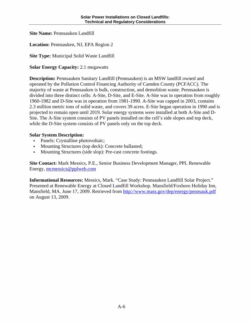
Solar Power Installations on Closed Landfills: Technical and Regulatory Considerations
A-6
Site Name: Pennsauken Landfill Location: Pennsauken, NJ, EPA Region 2 Site Type: Municipal Solid Waste Landfill Solar Energy Capacity: 2.1 megawatts Description: Pennsauken Sanitary Landfill (Pennsauken) is an MSW landfill owned and operated by the Pollution Control Financing Authority of Camden County (PCFACC). The majority of waste at Pennsauken is bulk, construction, and demolition waste. Pennsauken is divided into three distinct cells: A-Site, D-Site, and E-Site. A-Site was in operation from roughly 1960-1982 and D-Site was in operation from 1981-1990. A-Site was capped in 2003, contains 2.3 million metric tons of solid waste, and covers 39 acres. E-Site began operation in 1990 and is projected to remain open until 2019. Solar energy systems were installed at both A-Site and D-Site. The A-Site system consists of PV panels installed on the cell’s side slopes and top deck, while the D-Site system consists of PV panels only on the top deck. Solar System Description: Panels: Crystalline photovoltaic; Mounting Structures (top deck): Concrete ballasted; Mounting Structures (side slop): Pre-cast concrete footings.
Site Contact: Mark Messics, P.E., Senior Business Development Manager, PPL Renewable Energy, [email protected] Informational Resources: Messics, Mark. “Case Study: Pennsauken Landfill Solar Project.” Presented at Renewable Energy at Closed Landfill Workshop. Mansfield/Foxboro Holiday Inn, Mansfield, MA. June 17, 2009. Retrieved from http://www.mass.gov/dep/energy/pennsauk.pdf on August 13, 2009.