Embed Size (px)
Citation preview
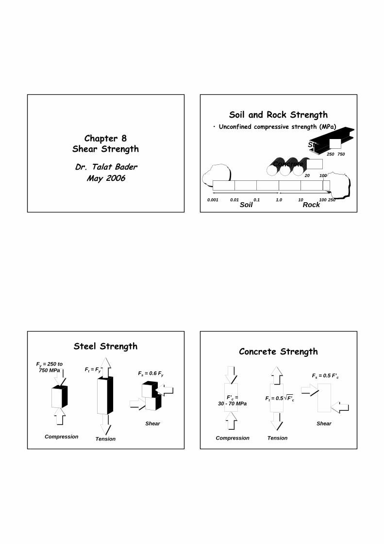
Chapter 8Shear Strength
Dr. Talat BaderMay 2006
Soil and Rock Strength• Unconfined compressive strength (MPa)
Concrete10020
1.0Rock
25010010Soil
0.10.010.001
Steel750250
Steel Strength
Compression
Fy = 250 to750 MPa
Tension
Ft = Fy
Shear
Fs = 0.6 Fy
Concrete Strength
Compression
F’c =30 - 70 MPa
Tension
Ft = 0.5 F’c√
Shear
Fs = 0.5 F’c

Sand Strength
W
≈ 0 ≈ 0
Compression Tension Shear
≈ 0
Confined strength
W W
Compression Tension Shear
σnτ
2W
Soil Confinement
Soil unit weight = γs
z σv = z * γs
σh = Ko * σv
Ko ≈ 1 - sinφ
The Direct Shear Test• Measuring directly
the normal and shearing stresses on a failure plane.
N Normal Load
TShearLoad
• The standard apparatus consists of a box 60 mm square although a larger 150 mm square box is available for coarse grained soils where the behaviour of the soil mass is important.
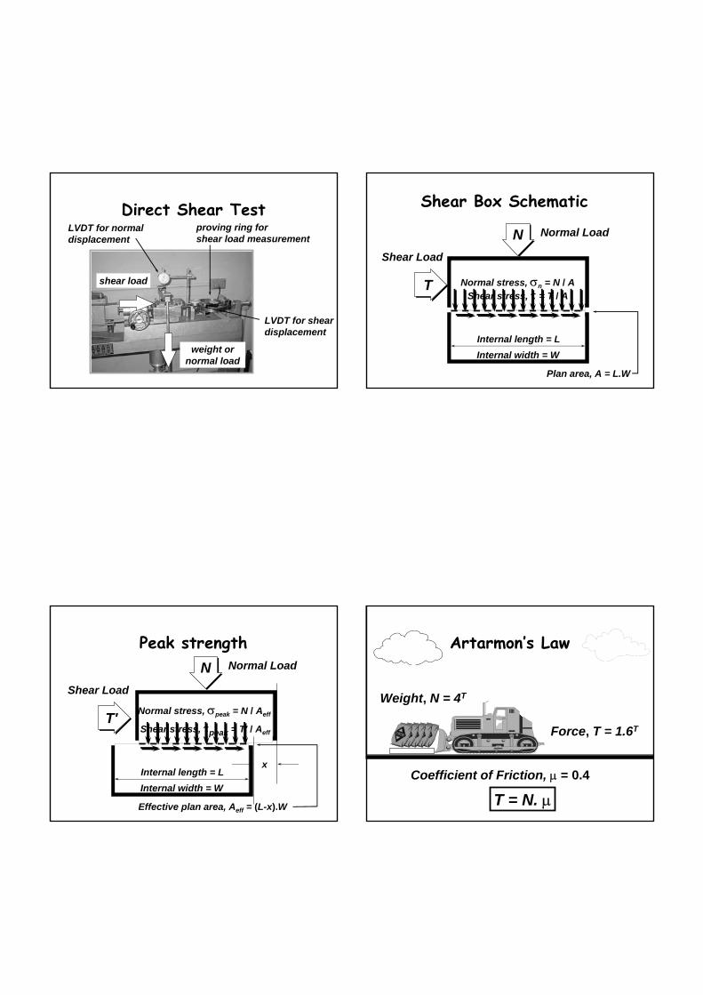
Direct Shear Test
weight ornormal load
shear load
proving ring forshear load measurement
LVDT for shear displacement
LVDT for normal displacement
Shear Box Schematic
N Normal Load
T
Shear Load
Internal length = LInternal width = W
Plan area, A = L.W
Normal stress, σn = N / AShear stress, τ = T / A
Peak strength
x
Effective plan area, Aeff = (L-x).W
N Normal Load
T'
Shear Load
Normal stress, σpeak = N / Aeff
Shear stress, τpeak = T' / Aeff
Internal length = LInternal width = W
Artarmon’s Law
Coefficient of Friction, µ = 0.4
Weight, N = 4T
Force, T = 1.6T
T = N. µ
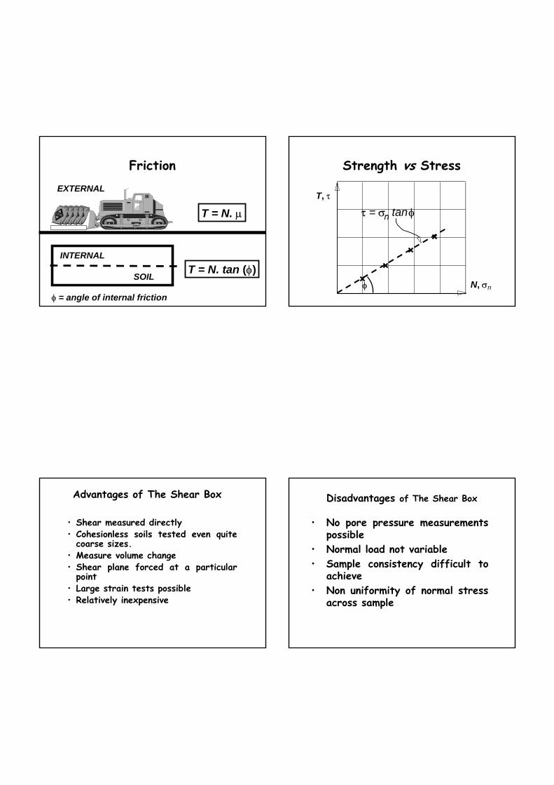
Friction
T = N. µ
T = N. tan (φ)
φ = angle of internal friction
EXTERNAL
INTERNAL
SOIL
Strength vs Stress
T, τ
N, σn
τ = σ. tanφn
φ
Advantages of The Shear Box
• Shear measured directly• Cohesionless soils tested even quite
coarse sizes.• Measure volume change• Shear plane forced at a particular
point• Large strain tests possible• Relatively inexpensive
Disadvantages of The Shear Box
• No pore pressure measurements possible
• Normal load not variable• Sample consistency difficult to
achieve• Non uniformity of normal stress
across sample

Mineral type and φ
• Steel 15o
• Timber 20o
• Quartz 30o
• Calcite 38o
• Kaolinite 15o
• Illite 10o
• Smectite 5o
Structural
Sands
Clays
Grain Shape and φ
Rounded 30 - 35o Sub-rounded 32 - 37o
Sub-angular 34-39o Angular 36-41o
T = N.µ = N.tan φ
slope ψ = 100
T = N. tan (φ + ψ)
4 x tan 32o= 2.5T
slope ψ = -100
N = 4T
µ = tan φ = 0.4⇒ φ = 22o
Inclination
4 x tan 12o
= 0.85T
Shear-deformation response
% Strain
τ = σn . tan (φ + ψ)
dense
τpeak
τresidualloose
Critical State
• A dense sand will reach a peak value and then fall to a level appropriate for a loose sand at large strains.
• The stress strain relationship for sands shows a slow rise to a steady value for a loose sand with slight densification creating a slight and apparent fall.
Shea
r Str
ess

Shearing Dense Sand
σn
τ
τ
e = 0.35
ψ
ψ = tan –1 (dy/dx)
Shearing Loose Sand
σn
τ
τ
e = 0.80
ψ
The Shear Behaviour of Sands and Clays• This is due to the packing of sand to
an optimal value followed by a rolling over of coarse grains at larger strains to loosen the packing.
• As the sample is sheared the particles (shown circular) move and adjust the packing
• Loosely packed sample densify packing closer together
• The densely packed samples when sheared may increase their densification slightly and then they start to rotate on individual particles and dilate. This densest point is called the critical state volume.
• The more single sized the sample the more marked the dilation.
Densification
DilationRotationover
particles
Dilation / Contraction+ dv
% Strain
Dense sands
ψmax …become looser asthe sample DILATES
Loose sands ψmax = 0
..become denser as the sample CONTRACTS
any behaviourin between
- dv

Cohesionless soiltypical of a medium SAND
T, τ
N, σn
τ = σ. tanφn
φNO FAILURE
FAILURE
Cohesive Soilstypically a sandy CLAY
τ
σn
Some soils, and all rocksdisplay some interparticlebonding, which gives them
strength even when the normalstress is zero - we call this
COHESION
c
τ = c + σ .tan φn
Mohr-Coulomb Equation
φ NO FAILURE
FAILURE
Shear Strength Failure Surface in Soils
• Near any geotechnical construction (e.g. slopes, excavations, tunnels and foundations) there will be both mean and normal stresses and shear stresses.
• The mean or normal stresses cause volume change due to compression or consolidation.
• The shear stresses prevent collapse and help to support the geotechnical structure.
• Shear stress may cause volume change.
• Failure will occur when the shear stress exceeds the limiting shear stress (strength).
WFailure not on a plane
W
Non-planar failure surface
To determine the strength along thefailure surface, we need to establishthe stresses at any point in the soil,and in any direction.

Soil stressesat a point
Soil unit weight = γs
z
Ko ≈ 1 - sinφ
σv = z * γs
σh = Ko * σv
Principal Stresses
F τ
•In a tiny element in the soil mass will have a number of principal stresses acting on it:-
•The major principal stress is σ1 and the minor principal stress is σ3, the intermediate stress is σ2 is ignored in the commonest form of analysis.
τ
σn
MOHR
σn
σ3
σ1
σ2
σ1
σ3τσ3 σ1
Mohr’s circle plotτ
σn
For horizontally deposited soil, there are noshear stresses in the vertical or horizontal directions
x
stress on horizontalsurface/plane
σvx
stress on verticalsurface/plane
σh 180o
= 90o in field90o
= 45o in field
σn = 0.5(σv + σh)
τ = 0.5(σv - σh)
Failure Criterionτ
σn
σvσh
τ = c + σ .tan φn
σv, failx x xx x
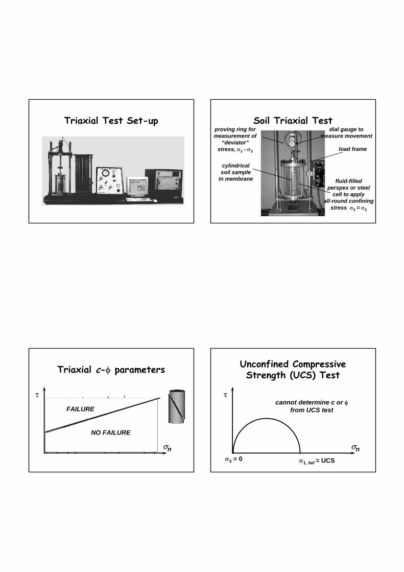
Triaxial Test Set-up Soil Triaxial Test
cylindricalsoil sample
in membrane fluid-filledperspex or steel
cell to applyall-round confining
stress σ2 = σ3
load frame
proving ring formeasurement of
“deviator”stress, σ1 - σ3
dial gauge tomeasure movement
Triaxial c-φ parameters
σn
τ
σ 3 σ1,fail
τ = c + σ tan φn
NO FAILURE
FAILURE
Unconfined CompressiveStrength (UCS) Test
σn
τ
σ3 = 0 σ1, fail = UCS
cannot determine c or φfrom UCS test

Shear Strength of Soils & Rocks
• Not a unique value (e.g. unlike mild steel)• Depends on
– geology– loading history– void ratio– water drainage conditions– rate of loading– depth (or confining stress)
σ h = γ H
Strength TestingDirect shear
• All soil but best for sand
• short drainage path, relatively quick test
• 60 x 60 x 20 mm confined in box
• no control of drainage or pore press.
Triaxial• best for clay• long drainage path,
relatively slow test• 54 mm diameter x 108 mm
long• control drainage, pore
press.pore pressure & volume change measurements possible.
σ
τ
σ 1 - σ 3
σ3
Types of Shear Test• The way in which we shear soil, in particular the
rate, will alter the type of shear strength parameters we obtain.
• DRAINED TEST: Alternatively if we shear the soil relatively slowly the pore pressures will dissipate and we refer to this test as a DRAINED TEST. The shear stresses are effective stresses and the shear strength parameters are:- c' , φ'
• UNDRAINED TEST: If we shear a soil relatively rapidly and the pore water pressures cannot dissipateor if we deliberately prevent dissipation by blocking drainage; the test is called an UNDRAINED TEST. The stresses will be total stresses and the shear strength parameters are referred to as:- cu , φu
Triaxial Testing for Effective Strength
• Two main types of tests– Drained (D)– Consolidated Undrained with Pore Pressure measurement (CUPP)
• Both involve 3 stages :– saturation– consolidation– shearing

Saturation stage
• Place sample in cell• Apply cell pressure and back pressure just less than cell pressure and leave
• test level of saturation using “B test”∆u = B ∆σ
• For S = 100%, B = 1, ∆u = ∆σ, ∆σ’ = 0
• if B > 0.95 then go to consolidation stage
Consolidation stage• Increase cell pressure by ∆σ3 to required
effective confining stress σ3’ = σ3 - uBP
• pore pressure will increase by ∆σ3 (ie an excess pore pressure of ∆u = ∆σ3 above back pressure)
• open drainage valves and allow excess pore pressures to dissipate - sample “consolidates”
• measure volume change of sample against time - coefficient of consolidation
• when volume stops changing shearing stage
Shearing StageD test
• leave back pressure lines open, i.e. drainage allowed
• apply vertical load at rate that allows complete drainage, i.e. no build-up in pore pressures
• measure load, volume change, displacement
• determine σ1’- σ3’ directly from axial load
• determine E’ and ν’ (from εv and εa)
CUPP test• close back pressure lines,
i.e. no volume change• apply vertical load at rate
that allows equilibrium of pore pressures
• measure load, pore pressure, displacement
• determine σ1 - σ3, u then σ1’, σ3’
• determine Eu, νu = 0.5
Drained Test
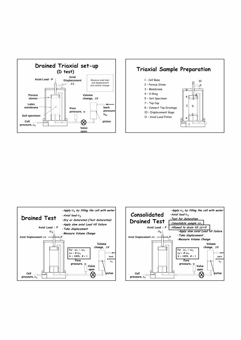
Axial Displacement
∆ LAxial Load - P
Cellpressure, σ3
Latexmembrane
Soil specimen
Drained Triaxial set-up (D test)
Porousstones
Pore pressure, u
back pressure ubp
Volume change, ∆V
piston
Measure axial loadand displacement
and volume change
Valveopen
Triaxial Sample Preparation
1 - Cell Base
1
2 – Porous Stone
24
4 – O-Ring3 – Membrane
3
5 – Soil Specimen
5
10 – Displacement Gage11 – Axial Load Piston
1011
4 7 8
9
7 – Top Cap2
8 – Connect Top Drainage
Drained Test
Axial Displacement ∆ L
•Apply σ3 by filling the cell with water
Cellpressure, σ3
σ3
Pore pressure, u
Valveopen
Volume change, ∆V
piston
Axial Load - P
•Axial load σ3
•Dry or Saturated (Test Saturation)•Apply slow axial Load till failure •Take displacement•Measure Volume Change
For ∆σ1 = ∆σ3∆u = B ∆σ3S = 100%, B = 1 back
pressure ubp
Consolidated Drained Test
Axial Displacement ∆ L
•Apply σ3 by filling the cell with water
Cellpressure, σ3
σ3
Pore pressure, u
Valveopen
Volume change, ∆V
piston
Axial Load - P
•Axial load σ3•Test for Saturation
•Apply slow axial Load till failure •Take displacement•Measure Volume Change
For ∆σ1 = ∆σ3∆u = B ∆σ3S = 100%, B = 1 back
pressure ubp
•Consolidate sample ∆σ1•Allowed to drain till ∆U=0
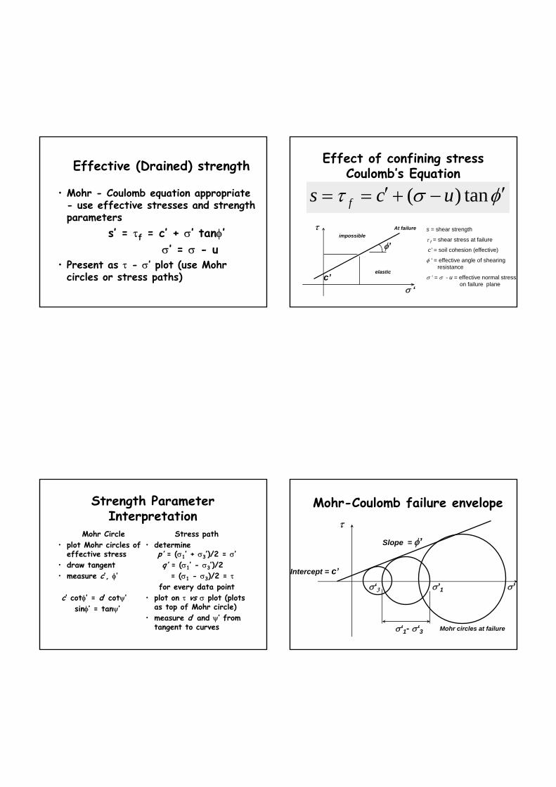
Effective (Drained) strength
• Mohr - Coulomb equation appropriate - use effective stresses and strength parameters
s’ = τf = c’ + σ’ tanφ’σ’ = σ - u
• Present as τ - σ’ plot (use Mohr circles or stress paths)
Effect of confining stress Coulomb’s Equation
φστ ′−+′== tan)( ucs f
c’
φ’
τ
σ ‘
elastic
impossibleAt failure s = shear strength
τ f = shear stress at failure
c’ = soil cohesion (effective)
φ ‘ = effective angle of shearing resistance
σ ‘ = σ - u = effective normal stress on failure plane
Strength Parameter Interpretation
Mohr Circle• plot Mohr circles of
effective stress• draw tangent• measure c’, φ’
c’ cotφ’ = d’ cotψ’sinφ’ = tanψ’
Stress path• determine
p’ = (σ1’ + σ3’)/2 = σ’q’ = (σ1’ - σ3’)/2
= (σ1 - σ3)/2 = τfor every data point
• plot on τ vs σ plot (plots as top of Mohr circle)
• measure d’ and ψ’ from tangent to curves
Mohr-Coulomb failure envelope
σ’1σ‘3
σ‘1- σ‘3
Slope = φ’
Intercept = c’
τ
Mohr circles at failure
σ’

Stress Path Method
Stress paths
• Alternative way of plotting results• follows stress state (top of Mohr’s circle) during shearing (loading)
• plot (p,q) for each data point, wherep = (σ1 + σ3)/2 = centre of circleq = (σ1 - σ3)/2= radius of circle = τ
Basis of stress path plot
σ
τ
σ 3
(σ 1 - σ 3)/2
(σ 1 + σ 3)/2
Stress path plot
q
p
d
Slope = ψ
Note c d, φ ψ but are related
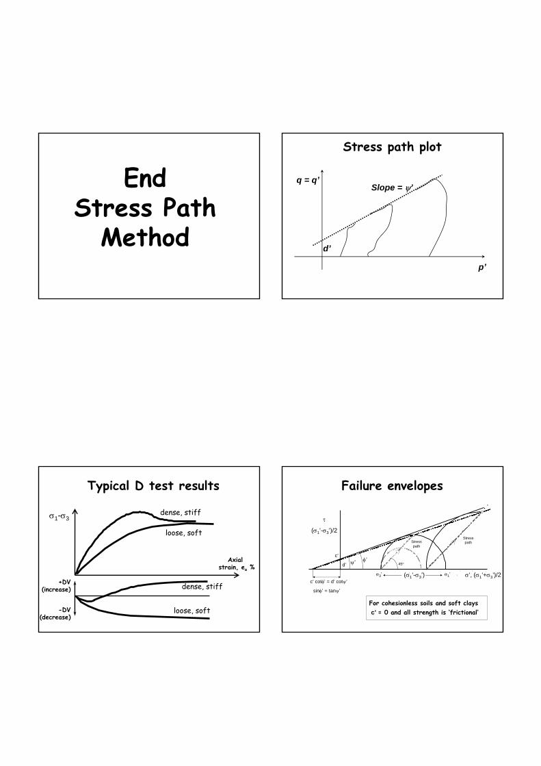
EndStress Path
Method
Stress path plot
q = q’
p’
d’
Slope = ψ’
Typical D test results
σ1-σ3
Axial strain, ea %
dense, stiff
dense, stiff+DV(increase)
-DV(decrease)
loose, soft
loose, soft
′′ ′
•
1
′ ′ ′
For cohesionless soils and soft claysc’ = 0 and all strength is ‘frictional’
Failure envelopes
τ
(σ1’-σ3’)/2StresspathStress
path
σ’, (σ1’+σ3’)/2
45oψ’ φ’d’
c’
c’ cotφ’ = d’ cotψ’
sinφ’ = tanψ’
σ1’σ3’ (σ1’-σ3’)
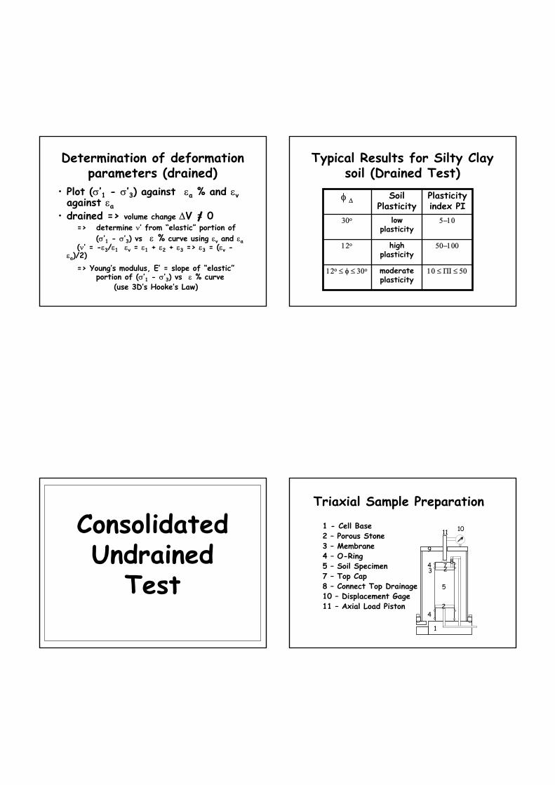
Determination of deformation parameters (drained)
• Plot (σ’1 - σ’3) against εa % and εvagainst εa
• drained => volume change ∆V = 0 => determine ν’ from “elastic” portion of
(σ’1 - σ’3) vs ε % curve using εv and εa(ν’ = -ε3/ε1 εv = ε1 + ε2 + ε3 => ε3 = (εv -
εa)/2)=> Young’s modulus, E’ = slope of “elastic”
portion of (σ’1 - σ’3) vs ε % curve(use 3D’s Hooke’s Law)
Typical Results for Silty Clay soil (Drained Test)
10 ≤ ΠΙ ≤ 50moderate plasticity
12ο ≤ φ ≤ 30ο
50−100high plasticity
12ο
5−10low plasticity
30ο
Plasticity index PI
Soil Plasticity
φ ∆
ConsolidatedUndrained
Test
Triaxial Sample Preparation
1 - Cell Base
1
2 – Porous Stone
24
4 – O-Ring3 – Membrane
35 – Soil Specimen
510 – Displacement Gage11 – Axial Load Piston
1011
4 7 8
9
7 – Top Cap2
8 – Connect Top Drainage

UndrainedTest
Axial Displacement ∆ L
•Apply σ3 by filling the cell with water
Cellpressure, σ3
σ3
Pore pressure, u
ValveClosed
No Volume change, ∆V=0
Axial Load - P
•Axial load σ3
•Test for Saturation•Apply slow axial Load till failure •Take displacement•Measure Pore Pressure
For ∆σ1 = ∆σ3∆u = B ∆σ3S = 100%, B = 1 back
pressure ubp
Consolidated Undrained Test
Axial Displacement ∆ L
•Apply σ3 by filling the cell with water
Cellpressure, σ3
σ3
Pore pressure, u
ValveClosed
No Volume change, ∆V = 0
Axial Load - P
•Axial load σ3
•Test for Saturation
•Apply slow axial Load till failure •Take displacement•Measure Pore Pressure
For ∆σ1 = ∆σ3∆u = B ∆σ3S = 100%, B = 1
•Allowed to drain till ∆U=0 (Valve Open)
back pressure
ubp
Pore Pressure Development• No volume change allowed pore
pressures develop• +ve pore pressures if sample tries to
consolidate (usually loose or soft)• -ve pore pressures if sample tries to
dilate (usually dense or stiff)• The “A” parameter (after Skempton) is a
measure of how much pore pressures will change during loading
Skempton’s Pore Pressure Parameters A & B
• Skempton (1954) proposed the following relationship relating pore pressures to total stresses
∆u = B [∆σ3 + A(∆σ1 - ∆σ3)]
• A and B are called Skempton’s pore pressure parameters
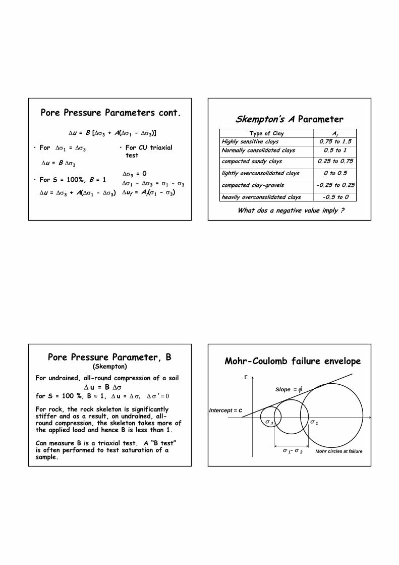
Pore Pressure Parameters cont.
∆u = B [∆σ3 + A(∆σ1 - ∆σ3)]
• For ∆σ1 = ∆σ3
∆u = B ∆σ3
• For S = 100%, B = 1
∆u = ∆σ3 + A(∆σ1 - ∆σ3)
• For CU triaxialtest
∆σ3 = 0 ∆σ1 - ∆σ3 = σ1 - σ3
∆uf = Af(σ1 - σ3)
Skempton’s A Parameter
What dos a negative value imply ?
-0.5 to 0heavily overconsolidated clays
-0.25 to 0.25compacted clay-gravels
0 to 0.5lightly overconsolidated clays
0.25 to 0.75compacted sandy clays
0.5 to 1Normally consolidated clays0.75 to 1.5Highly sensitive clays
AfType of Clay
Pore Pressure Parameter, B(Skempton)
For undrained, all-round compression of a soil∆ u = B ∆σ
for S = 100 %, B ≈ 1, ∆ u = ∆ σ, ∆ σ ’ = 0
For rock, the rock skeleton is significantly stiffer and as a result, on undrained, all-round compression, the skeleton takes more of the applied load and hence B is less than 1.
Can measure B is a triaxial test. A “B test”is often performed to test saturation of a sample.
Mohr-Coulomb failure envelope
σ 1σ 3
σ 1- σ 3
Slope = φ
Intercept = c
τ
Mohr circles at failure
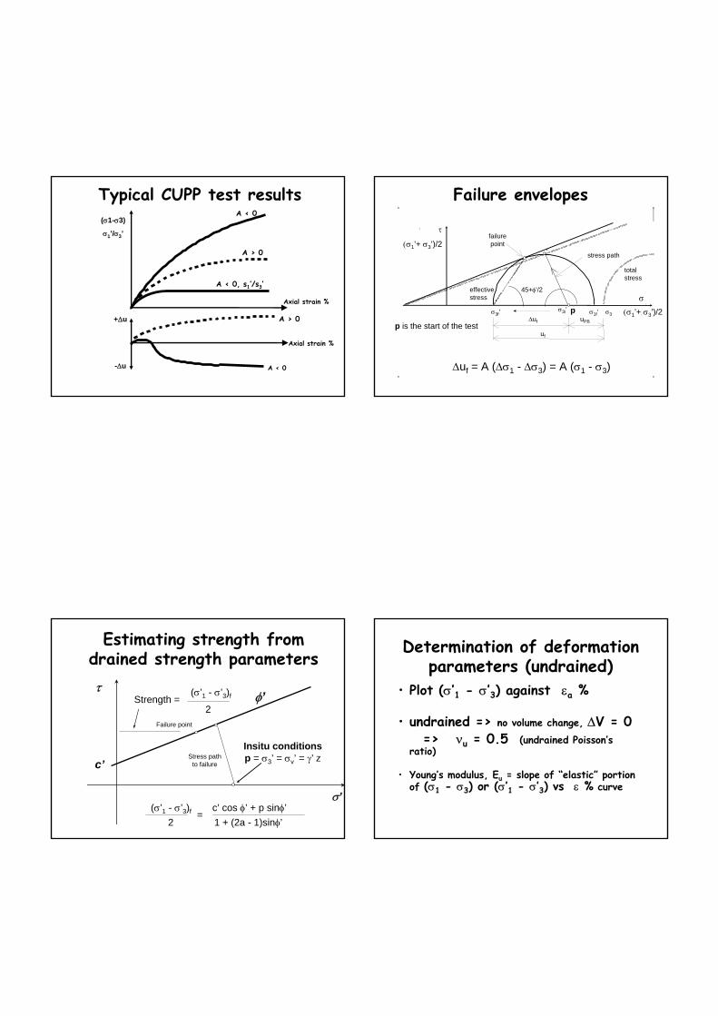
Typical CUPP test resultsA < 0
A > 0
A < 0
A > 0
A < 0, s1’/s3’
Axial strain %
Axial strain %
+∆u
-∆u
(σ1-σ3)
σ1’/σ3’
•
•
1
′
′
′
Failure envelopes
p σ1f’σ3f’ σ3 (σ1’+ σ3’)/2
totalstress
stress path
failurepoint
45+φ’/2
∆uf uPB
uf
effectivestress
τ
(σ1’+ σ3’)/2
σ
∆uf = A (∆σ1 - ∆σ3) = A (σ1 - σ3)
σ3i’
p is the start of the test
Estimating strength from drained strength parameters
φ’
c’
τ
σ’
Insitu conditions p = σ3’ = σv’ = γ’ z
Strength = 2
(σ’1 - σ’3)f
(σ’1 - σ’3)f c’ cos φ’ + p sinφ’2 1 + (2a - 1)sinφ’
=
Failure point
Stress pathto failure
Determination of deformation parameters (undrained)
• Plot (σ’1 - σ’3) against εa %
• undrained => no volume change, ∆V = 0 => νu = 0.5 (undrained Poisson’s
ratio)
• Young’s modulus, Eu = slope of “elastic” portion of (σ1 - σ3) or (σ’1 - σ’3) vs ε % curve

Summary : Strength
Undrained (total)• total stresses
• cu and φu
• not fundamental• saturation & pore
pressures unknown• short term
Drained (effective)• effective stresses
(σ’ = σ - u)• c’ and φ’, A and B• fundamental• saturation and pore
pressures known• long term
Analysis of Undrained TestDetermination of stresses
(σ1 - σ3) = P/AWhere
P = load
A = cross-sectional area
Correct for change in cross-sectional area(volume remains constant)
A = Ao/(1-ε)ε = axial strain = ∆L/Lo
Determination of deformation parameters
• Plot (σ1 - σ3) against ε %
• undrained => no volume change, ∆V = 0 => νu = 0.5 (undrained Poisson’s
ratio)
• Young’s modulus, Eu = slope of “elastic” portion of (σ1 - σ3) vs ε % curve
(use 3D’s Hooke’s Law to show this)
Determination of Eu
ε %
σ 1 - σ 3
Which line ?
Initial tangent
50% secant
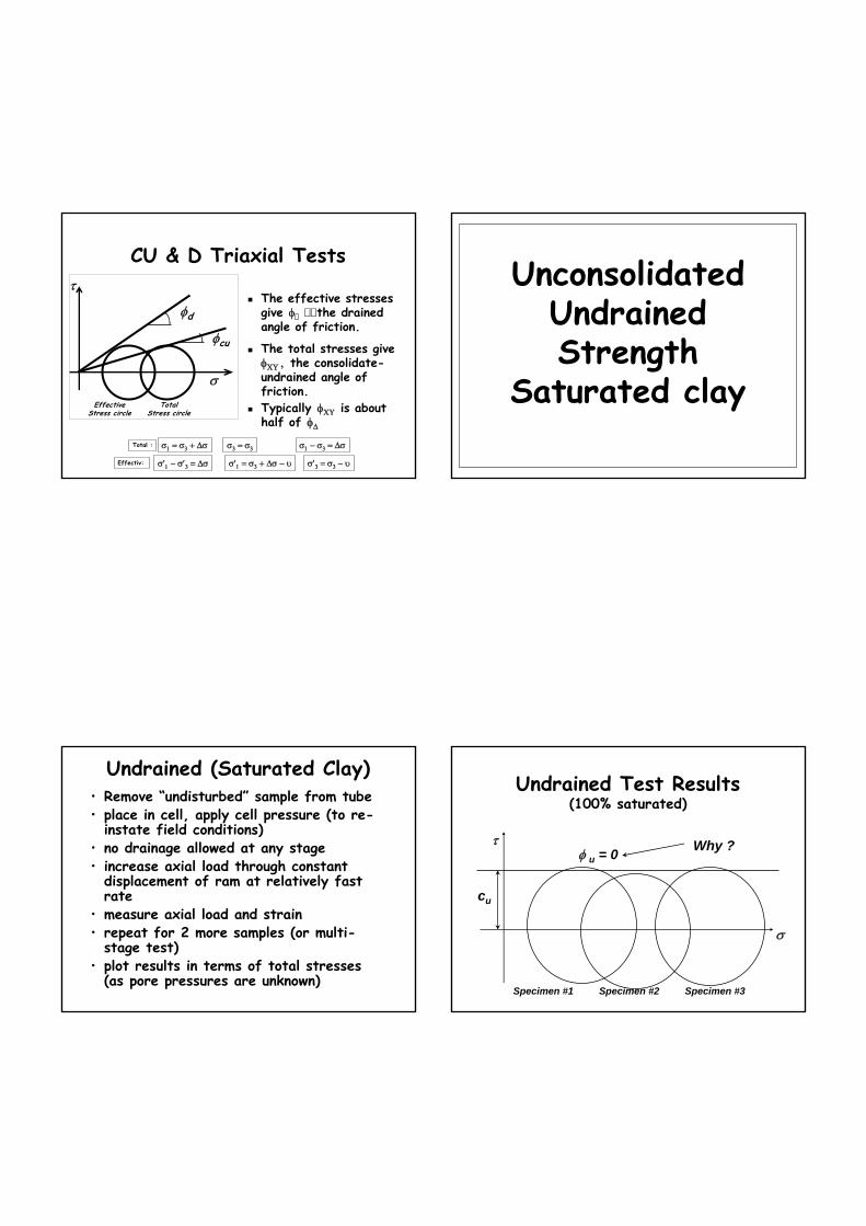
CU & D Triaxial Tests
σ1 = σ3 + ∆σ σ3 = σ3 σ1 − σ3 = ∆σTotal :
σ′1 = σ3 + ∆σ − υ σ′3 = σ3 − υσ′1 − σ′3 = ∆σEffectiv:
The effective stresses give φ the drained angle of friction.
τ
σ
φd
EffectiveStress circle
φcu
TotalStress circle
The total stresses giveφΧΥ , the consolidate-undrained angle of friction.Typically φΧΥ is about half of φ∆
UnconsolidatedUndrained Strength
Saturated clay
Undrained (Saturated Clay)• Remove “undisturbed” sample from tube• place in cell, apply cell pressure (to re-
instate field conditions)• no drainage allowed at any stage• increase axial load through constant
displacement of ram at relatively fast rate
• measure axial load and strain• repeat for 2 more samples (or multi-
stage test)• plot results in terms of total stresses
(as pore pressures are unknown)
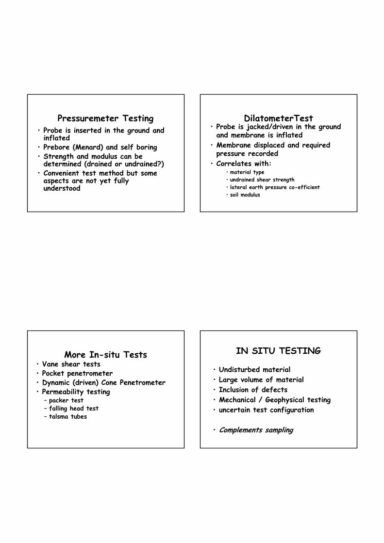
Undrained Test Results(100% saturated)
τ
σ
cu
φ u = 0 Why ?
Specimen #1 Specimen #3Specimen #2

Why does φu = 0 ?
∆ σ 3 = 100 kPa
=> ∆ u =100 kPatherefore, initially
∆ σ 3’ = ∆σ 3 - ∆ u= 100 - 100= 0
∆ σ 3 = 200 kPa
=> ∆ u = 200 kPatherefore, initially
∆ σ 3’ = ∆σ 3 - ∆ u= 200 - 200= 0
Consider two tests with different cell pressures
Skeleton relatively compressible, increase incell pressure is therefore carried by pore water
• Actual initial pore pressures are unknown (and are probably negative - why ?)
• pore pressures at failure are also unknown but they will differ by 100 kPa
• hence, at failure, major and minor principal effective stresses will be the same => both specimens plot as identical effective stress Mohr circles
• cu and φ u are not fundamental soil properties, but are products of testing method and interpretation
Undrained strength• Doesn’t matter what cell pressure is used
for testing• Why carry out more than one test ?• For samples obtained from different depths
- will undrained strength be different ?• Used for short term analyses (also called
total stress and undrained) of bearing capacity, slope stability etc problems
Undrained Strength Versus Depth
• In soft clays, cuvaries with depth
Dept
h, z
cu∆
Drying crust
cu /γ’z = const.
= cu /p
• In stiff clays, cu is approx. constant over limited depth range

Unsaturated soil/rock
• Most soil/rock above water table is partially saturated; S ~ 80 to 90 %
• why isn’t it dry ? (capillary action) => suctions
• B < 1 => for undrained conditions we will get some increase in effective stress (why ?)
• therefore may measure a friction angle
Friction angle - why ?
τ
σ
Limit for S = 100%
Degree of saturationincreases as confiningstress increases as air
forced into solution
φ u gradually reduces
until φ u = 0 at S = 100%
Sources of Error in TriaxialTest
• Sources of error within the triaxial test are:– sample disturbance– poor preparation– air bubbles in sample and in pore water lines
in drained tests– punctured membranes and poor seals– unsaturated soil– loading rate not appropriate for test– calibration of volume change– insensitivity of load frame....stiffness
Example 1 (Sandy Soil)• Since the stresses from the
foundation loads are quickly transferred to the soil skeleton, the foundation loads are carried by effective stresses.
• To determine whether or not shear failure would occur in the soil from the foundation loads, we would use a drained shear strength criterion with respect to the effective stresses in the soil mass.
Saturated,Sandy Soil
P

• In the short term the increased stresses from the foundation loads are quickly transferred to the soil skeleton and the pore fluid. In the short term, we would use an undrained shear strength failure criterion (χ= χυ, φ = 0) το assess possible shear failure.
• In the long term, the increased stresses from the foundation loads are carried by the soil skeleton via effective stresses. In the long term, we would use a drained shear strength failure criterion to assesspossible shear failure.
Saturated SiltyOr Clay Soils
P Example 2 (Clay Soil) Example 3• Assume that we are quickly
cutting a slope in a saturated clay soil deposit.
• In the short term, we would use an undrained shear strengthmodel to determine whether or not shear failure (or a slope failure) would occur.
• In the long term, we would use a drained shear strength model to determine
• whether or not shear failure (or a slope failure) would occur.
Saturated SiltyOr Clay Soils
ExcavaedSoils
Final Thoughts on Shear Strengths
Fine-grained soils
high SSA’s
low permeability's(drain slowly )
relevant strength istypically undrained
Coarse-grained soils
lowSSA’s
High permeability's(drain quickly)
relevant strength istypically drained
How To Determine Shear Strength in the Field?

In-situ Test
Methods
In-situ Testing• Soil is tested without extraction from the ground
• Provide:– preliminary or approximate design data
– in-situ properties where undisturbed sampling is not possible
• Advantages:– cheap– “On the spot” results
Standard Penetration Test (SPT)• Used primarily in granular soils• Crude form of testing but results are
widely accepted globally• Correlations
– relative density and friction angle– undrained cohesion– direct estimate of settlement
• Corrections - overburden pressure and PWP build-up
Cone Penetrometer Test (CPT)• Instrumented probe jacked into ground
at constant rate of penetration (2cm/sec)
• Cone resistance (qc) and sleeve friction (fs) measured
• cone resistance (qc) correlates with strength, and friction ratio (qc/fs)withmaterial type
• Should always be correlated with borehole information
Settlement and Bearing Correlations
Pressuremeter Testing• Probe is inserted in the ground and inflated
• Prebore (Menard) and self boring• Strength and modulus can be determined (drained or undrained?)
• Convenient test method but some aspects are not yet fully understood
DilatometerTest• Probe is jacked/driven in the ground and membrane is inflated
• Membrane displaced and required pressure recorded
• Correlates with:• material type• undrained shear strength• lateral earth pressure co-efficient• soil modulus
More In-situ Tests• Vane shear tests• Pocket penetrometer• Dynamic (driven) Cone Penetrometer• Permeability testing
– packer test– falling head test– talsma tubes
IN SITU TESTING
• Undisturbed material• Large volume of material• Inclusion of defects• Mechanical / Geophysical testing• uncertain test configuration
• Complements sampling

Mechanical in situ tests• Vane shear - torque on vane gives
undrained cohesive strength of soft clay• Hammering - Standard Penetration Test
(64 kg), Dynamic cone (9kg) -pavements.• Static (Dutch) Cone penetrometer.• Lateral pressure tests - pressuremeter
in bore hole, Camkometer, Flat plate dilatometer
• Trial footing / pile tests, CBR
Cone Penetrometer
• continuous record to define stratigraphy
• qc and fs• Friction angle of
sands• Undrained strength
of clays• Material type from
friction ratio = fs / qc
Cone
Sleeve
Measurement in borehole (i)
• Standard Penetration Test (SPT) very common world-wide– N < 10 very loose to loose– 30 < N < 50 dense– N > 50 very dense– correlations available between N and φ– beware - many correction factors proposed see Kulhawy for comprehensive treatment
Measurement in-situ (i)
• Cone penetration test (CPT) common in Europe, Australia, parts of US.– Correlations are available for φ based on cone resistance, qc
– Correlations also for soil type, based on qc and friction ratio

cu,φu
Triaxialτ
σ
c',φ'
Triaxial
σ’vσ’h
• Physical disturbance
• Does sample have same m.c. as in field?
• What is K ? i.e. is σ’h correct?
• Does σ’h1 = σ’h2?• Is σ1 vertical ?