Embed Size (px)
Citation preview

Software Testing and Analysis:Process, Principles, and
Techniques

Software Testing and Analysis:Process, Principles, and
Techniques
Mauro PezzeUniversita di Milano Bicocca
Michal YoungUniversity of Oregon

PUBLISHER Daniel SayreSENIOR PRODUCTION EDITOR Lisa WojcikEDITORIAL ASSISTANT Lindsay MurdockCOVER DESIGNER Madelyn LesureCOVER PHOTO Rick Fischer/MasterfileWILEY 200TH ANNIVERSARY LOGO DESIGN Richard J. Pacifico
This book was typeset by the authors using pdfLATEXand printed and boundby Malloy Lithographing. The cover was printed by Phoenix Color Corp.This book is printed on acid free paper. ∞
Copyright c© 2008 John Wiley & Sons, Inc. All rights reserved. No part of thispublication may be reproduced, stored in a retrieval system or transmitted in any form orby any means, electronic, mechanical, photocopying, recording, scanning or otherwise,except as permitted under Sections 107 or 108 of the 1976 United States Copyright Act,without either the prior written permission of the Publisher, or authorization throughpayment of the appropriate per-copy fee to the Copyright Clearance Center, Inc. 222Rosewood Drive, Danvers, MA 01923, website www.copyright.com. Requests to thePublisher for permission should be addressed to the Permissions Department, John Wiley& Sons, Inc., 111 River Street, Hoboken, NJ 07030-5774, (201) 748-6011, fax(201) 748-6008, website http://www.wiley.com/go/permissions.
To order books or for customer service please, call 1-800-CALL WILEY (225-5945).
ISBN-13 978-0-471-45593-6
Printed in the United States of America
10 9 8 7 5 6 4 3 2 1

Contents
List of Figures xi
List of Tables xv
I Fundamentals of Test and Analysis 1
1 Software Test and Analysis in a Nutshell 31.1 Engineering Processes and Verification . . . . . . . . . . . . . . . . 31.2 Basic Questions . . . . . . . . . . . . . . . . . . . . . . . . . . . . . 51.3 When Do Verification and Validation Start and End? . . . . . . . . . 51.4 What Techniques Should Be Applied? . . . . . . . . . . . . . . . . . 71.5 How Can We Assess the Readiness of a Product? . . . . . . . . . . . 101.6 How Can We Ensure the Quality of Successive Releases? . . . . . . . 111.7 How Can the Development Process Be Improved? . . . . . . . . . . 11
2 A Framework for Test and Analysis 152.1 Validation and Verification . . . . . . . . . . . . . . . . . . . . . . . 152.2 Degrees of Freedom . . . . . . . . . . . . . . . . . . . . . . . . . . 182.3 Varieties of Software . . . . . . . . . . . . . . . . . . . . . . . . . . 23
3 Basic Principles 293.1 Sensitivity . . . . . . . . . . . . . . . . . . . . . . . . . . . . . . . 293.2 Redundancy . . . . . . . . . . . . . . . . . . . . . . . . . . . . . . . 323.3 Restriction . . . . . . . . . . . . . . . . . . . . . . . . . . . . . . . 333.4 Partition . . . . . . . . . . . . . . . . . . . . . . . . . . . . . . . . . 353.5 Visibility . . . . . . . . . . . . . . . . . . . . . . . . . . . . . . . . 363.6 Feedback . . . . . . . . . . . . . . . . . . . . . . . . . . . . . . . . 36
4 Test and Analysis Activities Within a Software Process 394.1 The Quality Process . . . . . . . . . . . . . . . . . . . . . . . . . . 394.2 Planning and Monitoring . . . . . . . . . . . . . . . . . . . . . . . . 414.3 Quality Goals . . . . . . . . . . . . . . . . . . . . . . . . . . . . . . 424.4 Dependability Properties . . . . . . . . . . . . . . . . . . . . . . . . 434.5 Analysis . . . . . . . . . . . . . . . . . . . . . . . . . . . . . . . . 46
v

vi CONTENTS
4.6 Testing . . . . . . . . . . . . . . . . . . . . . . . . . . . . . . . . . 484.7 Improving the Process . . . . . . . . . . . . . . . . . . . . . . . . . 494.8 Organizational Factors . . . . . . . . . . . . . . . . . . . . . . . . . 50
II Basic Techniques 53
5 Finite Models 555.1 Overview . . . . . . . . . . . . . . . . . . . . . . . . . . . . . . . . 555.2 Finite Abstractions of Behavior . . . . . . . . . . . . . . . . . . . . 585.3 Control Flow Graphs . . . . . . . . . . . . . . . . . . . . . . . . . . 595.4 Call Graphs . . . . . . . . . . . . . . . . . . . . . . . . . . . . . . . 635.5 Finite State Machines . . . . . . . . . . . . . . . . . . . . . . . . . . 65
6 Dependence and Data Flow Models 776.1 Definition-Use Pairs . . . . . . . . . . . . . . . . . . . . . . . . . . 776.2 Data Flow Analysis . . . . . . . . . . . . . . . . . . . . . . . . . . . 826.3 Classic Analyses: Live and Avail . . . . . . . . . . . . . . . . . . . 856.4 From Execution to Conservative Flow Analysis . . . . . . . . . . . . 916.5 Data Flow Analysis with Arrays and Pointers . . . . . . . . . . . . . 946.6 Interprocedural Analysis . . . . . . . . . . . . . . . . . . . . . . . . 96
7 Symbolic Execution and Proof of Properties 1017.1 Symbolic State and Interpretation . . . . . . . . . . . . . . . . . . . 1027.2 Summary Information . . . . . . . . . . . . . . . . . . . . . . . . . 1047.3 Loops and Assertions . . . . . . . . . . . . . . . . . . . . . . . . . . 1057.4 Compositional Reasoning . . . . . . . . . . . . . . . . . . . . . . . 1087.5 Reasoning about Data Structures and Classes . . . . . . . . . . . . . 109
8 Finite State Verification 1138.1 Overview . . . . . . . . . . . . . . . . . . . . . . . . . . . . . . . . 1138.2 State Space Exploration . . . . . . . . . . . . . . . . . . . . . . . . 1168.3 The State Space Explosion Problem . . . . . . . . . . . . . . . . . . 1268.4 The Model Correspondence Problem . . . . . . . . . . . . . . . . . 1298.5 Granularity of Modeling . . . . . . . . . . . . . . . . . . . . . . . . 1318.6 Intensional Models . . . . . . . . . . . . . . . . . . . . . . . . . . . 1348.7 Model Refinement . . . . . . . . . . . . . . . . . . . . . . . . . . . 1388.8 Data Model Verification with Relational Algebra . . . . . . . . . . . 140
III Problems and Methods 149
9 Test Case Selection and Adequacy 1519.1 Overview . . . . . . . . . . . . . . . . . . . . . . . . . . . . . . . . 1519.2 Test Specifications and Cases . . . . . . . . . . . . . . . . . . . . . 1529.3 Adequacy Criteria . . . . . . . . . . . . . . . . . . . . . . . . . . . 1549.4 Comparing Criteria . . . . . . . . . . . . . . . . . . . . . . . . . . . 157
CONTENTS vii
10 Functional Testing 16110.1 Overview . . . . . . . . . . . . . . . . . . . . . . . . . . . . . . . . 16110.2 Random versus Partition Testing Strategies . . . . . . . . . . . . . . 16210.3 A Systematic Approach . . . . . . . . . . . . . . . . . . . . . . . . 16710.4 Choosing a Suitable Approach . . . . . . . . . . . . . . . . . . . . . 174
11 Combinatorial Testing 17911.1 Overview . . . . . . . . . . . . . . . . . . . . . . . . . . . . . . . . 18011.2 Category-Partition Testing . . . . . . . . . . . . . . . . . . . . . . . 18011.3 Pairwise Combination Testing . . . . . . . . . . . . . . . . . . . . . 18811.4 Catalog-Based Testing . . . . . . . . . . . . . . . . . . . . . . . . . 194
12 Structural Testing 21112.1 Overview . . . . . . . . . . . . . . . . . . . . . . . . . . . . . . . . 21212.2 Statement Testing . . . . . . . . . . . . . . . . . . . . . . . . . . . . 21512.3 Branch Testing . . . . . . . . . . . . . . . . . . . . . . . . . . . . . 21712.4 Condition Testing . . . . . . . . . . . . . . . . . . . . . . . . . . . . 21912.5 Path Testing . . . . . . . . . . . . . . . . . . . . . . . . . . . . . . . 22212.6 Procedure Call Testing . . . . . . . . . . . . . . . . . . . . . . . . . 22912.7 Comparing Structural Testing Criteria . . . . . . . . . . . . . . . . . 23012.8 The Infeasibility Problem . . . . . . . . . . . . . . . . . . . . . . . 230
13 Data Flow Testing 23513.1 Overview . . . . . . . . . . . . . . . . . . . . . . . . . . . . . . . . 23613.2 Definition-Use Associations . . . . . . . . . . . . . . . . . . . . . . 23613.3 Data Flow Testing Criteria . . . . . . . . . . . . . . . . . . . . . . . 23913.4 Data Flow Coverage with Complex Structures . . . . . . . . . . . . . 24113.5 The Infeasibility Problem . . . . . . . . . . . . . . . . . . . . . . . 243
14 Model-Based Testing 24514.1 Overview . . . . . . . . . . . . . . . . . . . . . . . . . . . . . . . . 24514.2 Deriving Test Cases from Finite State Machines . . . . . . . . . . . . 24614.3 Testing Decision Structures . . . . . . . . . . . . . . . . . . . . . . 25114.4 Deriving Test Cases from Control and Data Flow Graphs . . . . . . . 25714.5 Deriving Test Cases from Grammars . . . . . . . . . . . . . . . . . . 257
15 Testing Object-Oriented Software 27115.1 Overview . . . . . . . . . . . . . . . . . . . . . . . . . . . . . . . . 27115.2 Issues in Testing Object-Oriented Software . . . . . . . . . . . . . . 27215.3 An Orthogonal Approach to Test . . . . . . . . . . . . . . . . . . . . 28015.4 Intraclass Testing . . . . . . . . . . . . . . . . . . . . . . . . . . . . 28215.5 Testing with State Machine Models . . . . . . . . . . . . . . . . . . 28215.6 Interclass Testing . . . . . . . . . . . . . . . . . . . . . . . . . . . . 28615.7 Structural Testing of Classes . . . . . . . . . . . . . . . . . . . . . . 29315.8 Oracles for Classes . . . . . . . . . . . . . . . . . . . . . . . . . . . 29815.9 Polymorphism and Dynamic Binding . . . . . . . . . . . . . . . . . 301

viii CONTENTS
15.10 Inheritance . . . . . . . . . . . . . . . . . . . . . . . . . . . . . . . 30315.11 Genericity . . . . . . . . . . . . . . . . . . . . . . . . . . . . . . . . 30615.12 Exceptions . . . . . . . . . . . . . . . . . . . . . . . . . . . . . . . 308
16 Fault-Based Testing 31316.1 Overview . . . . . . . . . . . . . . . . . . . . . . . . . . . . . . . . 31316.2 Assumptions in Fault-Based Testing . . . . . . . . . . . . . . . . . . 31416.3 Mutation Analysis . . . . . . . . . . . . . . . . . . . . . . . . . . . 31516.4 Fault-Based Adequacy Criteria . . . . . . . . . . . . . . . . . . . . . 31916.5 Variations on Mutation Analysis . . . . . . . . . . . . . . . . . . . . 321
17 Test Execution 32717.1 Overview . . . . . . . . . . . . . . . . . . . . . . . . . . . . . . . . 32717.2 From Test Case Specifications to Test Cases . . . . . . . . . . . . . . 32817.3 Scaffolding . . . . . . . . . . . . . . . . . . . . . . . . . . . . . . . 32917.4 Generic versus Specific Scaffolding . . . . . . . . . . . . . . . . . . 33017.5 Test Oracles . . . . . . . . . . . . . . . . . . . . . . . . . . . . . . . 33217.6 Self-Checks as Oracles . . . . . . . . . . . . . . . . . . . . . . . . . 33417.7 Capture and Replay . . . . . . . . . . . . . . . . . . . . . . . . . . . 337
18 Inspection 34118.1 Overview . . . . . . . . . . . . . . . . . . . . . . . . . . . . . . . . 34118.2 The Inspection Team . . . . . . . . . . . . . . . . . . . . . . . . . . 34318.3 The Inspection Process . . . . . . . . . . . . . . . . . . . . . . . . . 34418.4 Checklists . . . . . . . . . . . . . . . . . . . . . . . . . . . . . . . . 34518.5 Pair Programming . . . . . . . . . . . . . . . . . . . . . . . . . . . 351
19 Program Analysis 35519.1 Overview . . . . . . . . . . . . . . . . . . . . . . . . . . . . . . . . 35519.2 Symbolic Execution in Program Analysis . . . . . . . . . . . . . . . 35619.3 Symbolic Testing . . . . . . . . . . . . . . . . . . . . . . . . . . . . 35819.4 Summarizing Execution Paths . . . . . . . . . . . . . . . . . . . . . 35919.5 Memory Analysis . . . . . . . . . . . . . . . . . . . . . . . . . . . . 36019.6 Lockset Analysis . . . . . . . . . . . . . . . . . . . . . . . . . . . . 36319.7 Extracting Behavior Models from Execution . . . . . . . . . . . . . 365
IV Process 373
20 Planning and Monitoring the Process 37520.1 Overview . . . . . . . . . . . . . . . . . . . . . . . . . . . . . . . . 37520.2 Quality and Process . . . . . . . . . . . . . . . . . . . . . . . . . . . 37620.3 Test and Analysis Strategies . . . . . . . . . . . . . . . . . . . . . . 37720.4 Test and Analysis Plans . . . . . . . . . . . . . . . . . . . . . . . . 38220.5 Risk Planning . . . . . . . . . . . . . . . . . . . . . . . . . . . . . . 38620.6 Monitoring the Process . . . . . . . . . . . . . . . . . . . . . . . . . 389

CONTENTS ix
20.7 Improving the Process . . . . . . . . . . . . . . . . . . . . . . . . . 39420.8 The Quality Team . . . . . . . . . . . . . . . . . . . . . . . . . . . 399
21 Integration and Component-based Software Testing 40521.1 Overview . . . . . . . . . . . . . . . . . . . . . . . . . . . . . . . . 40521.2 Integration Testing Strategies . . . . . . . . . . . . . . . . . . . . . . 40821.3 Testing Components and Assemblies . . . . . . . . . . . . . . . . . 413
22 System, Acceptance, and Regression Testing 41722.1 Overview . . . . . . . . . . . . . . . . . . . . . . . . . . . . . . . . 41722.2 System Testing . . . . . . . . . . . . . . . . . . . . . . . . . . . . . 41822.3 Acceptance Testing . . . . . . . . . . . . . . . . . . . . . . . . . . . 42122.4 Usability . . . . . . . . . . . . . . . . . . . . . . . . . . . . . . . . 42322.5 Regression Testing . . . . . . . . . . . . . . . . . . . . . . . . . . . 42722.6 Regression Test Selection Techniques . . . . . . . . . . . . . . . . . 42822.7 Test Case Prioritization and Selective Execution . . . . . . . . . . . . 434
23 Automating Analysis and Test 43923.1 Overview . . . . . . . . . . . . . . . . . . . . . . . . . . . . . . . . 43923.2 Automation and Planning . . . . . . . . . . . . . . . . . . . . . . . 44123.3 Process Management . . . . . . . . . . . . . . . . . . . . . . . . . . 44123.4 Static Metrics . . . . . . . . . . . . . . . . . . . . . . . . . . . . . . 44323.5 Test Case Generation and Execution . . . . . . . . . . . . . . . . . . 44523.6 Static Analysis and Proof . . . . . . . . . . . . . . . . . . . . . . . . 44523.7 Cognitive Aids . . . . . . . . . . . . . . . . . . . . . . . . . . . . . 44823.8 Version Control . . . . . . . . . . . . . . . . . . . . . . . . . . . . . 44923.9 Debugging . . . . . . . . . . . . . . . . . . . . . . . . . . . . . . . 44923.10 Choosing and Integrating Tools . . . . . . . . . . . . . . . . . . . . 451
24 Documenting Analysis and Test 45524.1 Overview . . . . . . . . . . . . . . . . . . . . . . . . . . . . . . . . 45524.2 Organizing Documents . . . . . . . . . . . . . . . . . . . . . . . . . 45624.3 Test Strategy Document . . . . . . . . . . . . . . . . . . . . . . . . 45824.4 Analysis and Test Plan . . . . . . . . . . . . . . . . . . . . . . . . . 45824.5 Test Design Specification Documents . . . . . . . . . . . . . . . . . 46024.6 Test and Analysis Reports . . . . . . . . . . . . . . . . . . . . . . . 462
Bibliography 467
Index 479

x CONTENTS

List of Figures
1 Selective reading . . . . . . . . . . . . . . . . . . . . . . . . . . . . xxi
1.1 Analysis and testing activities . . . . . . . . . . . . . . . . . . . . . 9
2.1 Validation and verification . . . . . . . . . . . . . . . . . . . . . . . 162.2 Verification trade-off dimensions . . . . . . . . . . . . . . . . . . . . 19
3.1 Unpredictable failure and predictable failure . . . . . . . . . . . . . 313.2 Initialize before use problem . . . . . . . . . . . . . . . . . . . . . . 34
4.1 Dependability properties . . . . . . . . . . . . . . . . . . . . . . . . 46
5.1 Abstraction coalesces execution states . . . . . . . . . . . . . . . . . 585.2 Constructing control flow graphs . . . . . . . . . . . . . . . . . . . . 595.3 Java method to collapse adjacent newline characters . . . . . . . . . 615.4 Statements broken across basic blocks . . . . . . . . . . . . . . . . . 625.5 Linear-code sequence and jump (LCSAJ) . . . . . . . . . . . . . . . 625.6 Over-approximation in a call graph . . . . . . . . . . . . . . . . . . 645.7 Context sensitivity . . . . . . . . . . . . . . . . . . . . . . . . . . . 665.8 Exponential explosion of calling contexts in a call graph . . . . . . . 675.9 Finite state machine specification of line-end conversion procedure . 695.10 Correctness relations for a finite state machine model . . . . . . . . . 705.11 Procedure to convert among Dos, Unix, and Macintosh line ends . . . 725.12 Completed FSM specification of line-end conversion procedure . . . 73
6.1 GCD calculation in Java . . . . . . . . . . . . . . . . . . . . . . . . 786.2 Control flow graph of GCD method . . . . . . . . . . . . . . . . . . 796.3 Data dependence graph of GCD method . . . . . . . . . . . . . . . . 806.4 Calculating control dependence . . . . . . . . . . . . . . . . . . . . 816.5 Control dependence tree of GCD method . . . . . . . . . . . . . . . 826.6 Reaching definitions algorithm . . . . . . . . . . . . . . . . . . . . . 846.7 Available expressions algorithm . . . . . . . . . . . . . . . . . . . . 866.8 Java method with potentially uninitialized variable . . . . . . . . . . 876.9 Control flow with definitions and uses . . . . . . . . . . . . . . . . . 886.10 Annotated CFG for detecting uses of uninitialized variables . . . . . 89
xi

xii LIST OF FIGURES
6.11 CGI program in Python with misspelled variable . . . . . . . . . . . 916.12 Powerset lattice . . . . . . . . . . . . . . . . . . . . . . . . . . . . . 936.13 Spurious execution paths in interprocedural analysis . . . . . . . . . 97
7.1 Binary search procedure . . . . . . . . . . . . . . . . . . . . . . . . 1037.2 Concrete and symbolic tracing . . . . . . . . . . . . . . . . . . . . . 104
8.1 Finite state verification . . . . . . . . . . . . . . . . . . . . . . . . . 1158.2 Misapplication of the double-check initialization pattern . . . . . . . 1188.3 FSM models from Figure 8.2 . . . . . . . . . . . . . . . . . . . . . . 1198.4 Promela finite state model . . . . . . . . . . . . . . . . . . . . . . . 1208.5 Excerpts of Spin verification tool transcript . . . . . . . . . . . . . . 1218.6 Spin guided simulation trace describing race condition . . . . . . . . 1238.7 A graphical interpretation of Spin guided simulation trace . . . . . . 1248.8 Dining philosophers in Promela . . . . . . . . . . . . . . . . . . . . 1288.9 A simple data race in Java . . . . . . . . . . . . . . . . . . . . . . . 1318.10 Coarse and fine-grain models of interleaving . . . . . . . . . . . . . 1328.11 Lost update problem . . . . . . . . . . . . . . . . . . . . . . . . . . 1338.12 OBDD encoding of a propositional formula . . . . . . . . . . . . . . 1368.13 OBDD representation of transition relation . . . . . . . . . . . . . . 1378.14 Data model of a simple Web site . . . . . . . . . . . . . . . . . . . . 1418.15 Alloy model of a Web site. . . . . . . . . . . . . . . . . . . . . . . . 1428.16 Alloy model of a Web site (continued) . . . . . . . . . . . . . . . . . 1438.17 A Web site that violates the “browsability” property . . . . . . . . . 145
9.1 A Java method for collapsing sequences of blanks . . . . . . . . . . . 155
10.1 A Java class for finding roots of a quadratic equation . . . . . . . . . 16510.2 A quasi-partition of a program’s input domain . . . . . . . . . . . . . 16710.3 The functional testing process . . . . . . . . . . . . . . . . . . . . . 169
11.1 Specification of Check configuration . . . . . . . . . . . . . . . . . . 18211.2 Specification of cgi decode . . . . . . . . . . . . . . . . . . . . . . . 19511.3 Elementary items of specification cgi decode . . . . . . . . . . . . . 19811.4 Test case specifications for cgi decode generated after step 2 . . . . . 201
12.1 The C function cgi decode . . . . . . . . . . . . . . . . . . . . . . . 21312.2 Control flow graph of function cgi decode . . . . . . . . . . . . . . . 21412.3 The control flow graph of C function cgi decode′ . . . . . . . . . . . 21812.4 Deriving a tree from a control flow graph for boundary/interior testing 22312.5 Buggy self-organizing list . . . . . . . . . . . . . . . . . . . . . . . 22412.6 Control flow graph of C function search . . . . . . . . . . . . . . . . 22512.7 Tree of boundary/interior sub-paths for C function search . . . . . . 22612.8 Subsumption relations among structural test adequacy criteria . . . . 231
13.1 The C function cgi decode . . . . . . . . . . . . . . . . . . . . . . . 23713.2 A C procedure with a large number of DU paths . . . . . . . . . . . 241

LIST OF FIGURES xiii
13.3 Pointer arithmetic . . . . . . . . . . . . . . . . . . . . . . . . . . . . 242
14.1 Functional specification of feature Maintenance . . . . . . . . . . . . 24714.2 The finite state machine corresponding to Maintenance . . . . . . . . 24814.3 Functional specification of feature Pricing . . . . . . . . . . . . . . . 25214.4 Decision table for Pricing . . . . . . . . . . . . . . . . . . . . . . . 25414.5 Set of test cases corresponding to the modified adequacy criterion . . 25614.6 Functional specification of Process shipping order . . . . . . . . . . 25814.7 Control flow model of Process shipping order . . . . . . . . . . . . 25914.8 Node-adequate test suite . . . . . . . . . . . . . . . . . . . . . . . . 26014.9 Branch-adequate test suite . . . . . . . . . . . . . . . . . . . . . . . 26014.10 Functional specification of Advanced search . . . . . . . . . . . . . . 26114.11 BNF description of Advanced search . . . . . . . . . . . . . . . . . 26114.12 XML schema for Product configuration . . . . . . . . . . . . . . . . 26314.13 BNF description of Product configuration . . . . . . . . . . . . . . . 26414.14 Test case for feature Advanced Search . . . . . . . . . . . . . . . . . 26414.15 The BNF description of Product Configuration . . . . . . . . . . . . 26514.16 Sample seed probabilities for the BNF of Product Configuration . . . 266
15.1 Part of a Java implementation of class Model . . . . . . . . . . . . . 27415.2 More of the Java implementation of class Model . . . . . . . . . . . . 27515.3 Class diagram for the LineItem hierarchy. . . . . . . . . . . . . . . . 27615.4 Part of a Java implementation of class Account. . . . . . . . . . . . . 27815.5 Impact of object-oriented design on analysis and test. . . . . . . . . . 27915.6 Statechart specification of class Model . . . . . . . . . . . . . . . . . 28415.7 Finite state machine corresponding to the statechart in Figure 15.6 . . 28515.8 Statechart specification of class Order . . . . . . . . . . . . . . . . . 28715.9 Finite state machine corresponding to the statechart in Figure 15.8 . . 28815.10 Class diagram of the Chipmunk Web presence . . . . . . . . . . . . 29015.11 Use/include relation for the class diagram in Figure 15.10 . . . . . . 29115.12 Sequence diagram for configuring an order . . . . . . . . . . . . . . 29415.13 Partial intraclass control flow graph for class Model . . . . . . . . . . 29615.14 Summary information for structural interclass testing . . . . . . . . . 29915.15 Polymorphic method call . . . . . . . . . . . . . . . . . . . . . . . . 30215.16 Part of a Java implementation of the abstract class LineItem . . . . . . 30515.17 Part of a Java implementation of class CompositeItem . . . . . . . . . 307
16.1 Program transduce . . . . . . . . . . . . . . . . . . . . . . . . . . . 31716.2 Sample mutation operators for C . . . . . . . . . . . . . . . . . . . . 31816.3 Sample mutants for program Transduce . . . . . . . . . . . . . . . . 32016.4 Edit distance check . . . . . . . . . . . . . . . . . . . . . . . . . . . 325
17.1 JUnit tests in JFlex . . . . . . . . . . . . . . . . . . . . . . . . . . . 33117.2 Test harness with comparison-based test oracle . . . . . . . . . . . . 33317.3 Testing with self-checks . . . . . . . . . . . . . . . . . . . . . . . . 33417.4 Structural invariant as run-time self-check . . . . . . . . . . . . . . . 336

xiv LIST OF FIGURES
18.1 Detailed description referenced by a checklist item. . . . . . . . . . . 349
19.1 A C program invoking cgi decode . . . . . . . . . . . . . . . . . . . 36119.2 Purify verification tool transcript. . . . . . . . . . . . . . . . . . . . 36219.3 Model of memory states . . . . . . . . . . . . . . . . . . . . . . . . 36319.4 Concurrent threads with shared variables . . . . . . . . . . . . . . . 36419.5 Lockset state transition diagram . . . . . . . . . . . . . . . . . . . . 36519.6 A Java method for inserting a node in an AVL tree . . . . . . . . . . 36719.7 Sample set of predicates for behavior program analysis . . . . . . . . 36819.8 Test cases for an AVL tree . . . . . . . . . . . . . . . . . . . . . . . 36919.9 Behavioral models for method insert . . . . . . . . . . . . . . . . . . 370
20.1 Alternative schedules . . . . . . . . . . . . . . . . . . . . . . . . . . 38520.2 A sample A&T schedule . . . . . . . . . . . . . . . . . . . . . . . . 38720.3 Typical fault distribution over time . . . . . . . . . . . . . . . . . . . 392
21.1 Chipmunk Web presence hierarchy . . . . . . . . . . . . . . . . . . 411
22.1 Version 1.0 of the C function cgi decode . . . . . . . . . . . . . . . 43022.2 Version 2.0 of the C function cgi decode . . . . . . . . . . . . . . . 43122.3 Coverage of structural test cases for cgi decode . . . . . . . . . . . . 43222.4 Control flow graph of function cgi decode version 2.0 . . . . . . . . 43322.5 New definitions and uses for cgi decode . . . . . . . . . . . . . . . . 43422.6 Flow graph model of the extended shipping order specification . . . . 435
23.1 CodeCrawler code size visualization . . . . . . . . . . . . . . . . . . 450
24.1 Sample document naming conventions . . . . . . . . . . . . . . . . . 456

List of Tables
11.1 Example categories and value classes . . . . . . . . . . . . . . . . . 18711.2 Test case specifications for Check configuration . . . . . . . . . . . . 18911.3 Parameters and values for Display control . . . . . . . . . . . . . . . 19011.4 Pairwise coverage of three parameters . . . . . . . . . . . . . . . . . 19111.5 Pairwise coverage of five parameters . . . . . . . . . . . . . . . . . . 19211.6 Constraints for Display control . . . . . . . . . . . . . . . . . . . . . 19311.7 A test catalog . . . . . . . . . . . . . . . . . . . . . . . . . . . . . . 20211.8 Summary of catalog-based test cases for cgi decode . . . . . . . . . . 205
12.1 Test cases for cgi decode . . . . . . . . . . . . . . . . . . . . . . . . 215
13.1 Definitions and uses for C function cgi decode . . . . . . . . . . . . 23813.2 DU pairs for C function cgi decode . . . . . . . . . . . . . . . . . . 239
14.1 A test suite derived from the FSM of Figure 14.2 . . . . . . . . . . . 249
15.1 Test cases to satisfy transition coverage criterion . . . . . . . . . . . . 28515.2 Simple transition coverage . . . . . . . . . . . . . . . . . . . . . . . 28915.3 Equivalent scenarios . . . . . . . . . . . . . . . . . . . . . . . . . . 30115.4 Pairwise combinatorial coverage of polymorphic binding . . . . . . . 30215.5 Testing history for class LineItem . . . . . . . . . . . . . . . . . . . . 30415.6 Testing history for class CompositeItem . . . . . . . . . . . . . . . . 306
20.1 Standard severity levels for root cause analysis . . . . . . . . . . . . . 397
21.1 Integration faults. . . . . . . . . . . . . . . . . . . . . . . . . . . . . 407
xv

xvi LIST OF TABLES

Preface
This book addresses software test and analysis in the context of an overall effort toachieve quality. It is designed for use as a primary textbook for a course in softwaretest and analysis or as a supplementary text in a software engineering course, and as aresource for software developers.
The main characteristics of this book are:
• It assumes that the reader’s goal is to achieve a suitable balance of cost, sched-ule, and quality. It is not oriented toward critical systems for which ultra-highreliability must be obtained regardless of cost, nor will it be helpful if one’s aimis to cut cost or schedule regardless of consequence.
• It presents a selection of techniques suitable for near-term application, with suf-ficient technical background to understand their domain of applicability and toconsider variations to suit technical and organizational constraints. Techniquesof only historical interest and techniques that are unlikely to be practical in thenear future are omitted.
• It promotes a vision of software testing and analysis as integral to modern soft-ware engineering practice, equally as important and technically demanding asother aspects of development. This vision is generally consistent with currentthinking on the subject, and is approached by some leading organizations, but isnot universal.
• It treats software testing and static analysis techniques together in a coherentframework, as complementary approaches for achieving adequate quality at ac-ceptable cost.
Why This Book?
One cannot “test quality into” a badly constructed software product, but neither can onebuild quality into a product without test and analysis. The goal of acceptable qualityat acceptable cost is both a technical and a managerial challenge, and meeting the goalrequires a grasp of both the technical issues and their context in software development.
xvii

xviii Preface
It is widely acknowledged today that software quality assurance should not be aphase between development and deployment, but rather a set of ongoing activities in-terwoven with every task from initial requirements gathering through evolution of thedeployed product. Realization of this vision in practice is often only partial. It requirescareful choices and combinations of techniques fit to the organization, products, andprocesses, but few people are familiar with the full range of techniques, from inspectionto testing to automated analyses. Those best positioned to shape the organization andits processes are seldom familiar with the technical issues, and vice versa. Moreover,there still persists in many organizations a perception that quality assurance requiresless skill or background than other aspects of development.
This book provides students with a coherent view of the state of the art and practice,and provides developers and managers with technical and organizational approaches topush the state of practice toward the state of the art.
Who Is This Book For?
Students who read portions of this book will gain a basic understanding of principlesand issues in software test and analysis, including an introduction to process and or-ganizational issues. Developers, including quality assurance professionals, will find avariety of techniques with sufficient discussion of technical and process issues to sup-port adaptation to the particular demands of their organization and application domain.Technical managers will find a coherent approach to weaving software quality assur-ance into the overall software process. All readers should obtain a clearer view of theinterplay among technical and nontechnical issues in crafting an approach to softwarequality.
Students, developers, and technical managers with a basic background in computerscience and software engineering will find the material in this book accessible withoutadditional preparation. Some of the material is technically demanding, but readers mayskim it on a first reading to get the big picture, and return to it at need.
A basic premise of this book is that effective quality assurance is best achievedby selection and combination of techniques that are carefully woven into (not graftedonto) a software development process for a particular organization. A software qualityengineer seeking technical advice will find here encouragement to consider a widercontext and participate in shaping the development process. A manager whose faithlies entirely in process, to the exclusion of technical knowledge and judgment, willfind here many connections between technical and process issues, and a rationale for amore comprehensive view.
How to Read This Book
This book is designed to permit selective reading. Most readers should begin withPart I, which presents fundamental principles in a coherent framework and lays thegroundwork for understanding the strengths and weaknesses of individual techniquesand their application in an effective software process. Part II brings together basic tech-

xix
nical background for many testing and analysis methods. Those interested in particularmethods may proceed directly to the relevant chapters in Part III of the book. Wherethere are dependencies, the Required Background section at the beginning of a chap-ter indicates what should be read in preparation. Part IV discusses how to design asystematic testing and analysis process and incorporates it into an overall developmentprocess, and may be read either before or after Part III.
Readers new to the field of software test and analysis can obtain an overview by readingChapters
1 Software Test and Analysis in a nutshell2 A Framework for Test and Analysis4 Test and Analysis Activities within a Software Process10 Functional Testing11 Combinatorial Testing14 Model-Based Testing15 Testing Object-Oriented Software17 Test Execution18 Inspection19 Program Analysis20 Planning and Monitoring the Process
Notes for Instructors
This book can be used in an introductory course in software test and analysis or as asupplementary text in an undergraduate software engineering course.
An introductory graduate-level or an undergraduate level course in software test andanalysis can cover most of the book. In particular, it should include
• All of Part I (Fundamentals of Test and Analysis), which provides a completeoverview.
• Most of Part II (Basic Techniques), which provides fundamental background,possibly omitting the latter parts of Chapters 6 (Dependence and Data FlowModels) and 7 (Symbolic Execution and Proof of Properties). These chapters areparticularly suited for students who focus on theoretical foundations and thosewho plan to study analysis and testing more deeply.
• A selection of materials from Parts III (Problems and Methods) and IV (Process).
For a course with more emphasis on techniques than process, we recommend
• Chapter 10 (Functional Testing), to understand how to approach black-box test-ing.
• The overview section and at least one other section of Chapter 11 (CombinatorialTesting) to grasp some combinatorial techniques.

xx Preface
• Chapter 12 (Structural Testing), through Section 12.3, to introduce the basic cov-erage criteria.
• Chapter 13 (Data Flow Testing), through Section 13.3, to see an important appli-cation of data flow analysis to software testing.
• The overview section and at least one other section of Chapter 14 (Model-basedTesting) to grasp the interplay between models and testing.
• Chapter 15 (Testing Object-Oriented Software) to appreciate implications of theobject-oriented paradigm on analysis and testing.
• Chapter 17 (Test Execution), to manage an easily overlooked set of problemsand costs.
• Chapter 18 (Inspection) to grasp the essential features of inspection and appreci-ate the complementarity of analysis and test.
• Chapter 19 (Program Analysis) to understand the role of automated programanalyses and their relation to testing and inspection techniques.
• Chapters 20 (Planning and Monitoring the Process), 21 (Integration and Component-based Software Testing), and 22 (System, Acceptance, and Regression Testing)to widen the picture of the analysis and testing process.
For a stronger focus on software process and organizational issues, we recommend
• Chapter 10 (Functional Testing), a selection from Chapters 11 and 14 (Com-binatorial Testing and Model-Based Testing), and Chapters 15 (Testing Object-Oriented Software), 17 (Test Execution), 18 (Inspection), and 19 (Program Anal-ysis) to provide a basic overview of techniques.
• Part IV, possibly omitting Chapter 23 (Automating Analysis and Test), for acomprehensive view of the quality process.
When used as a supplementary text in an undergraduate software engineering course,Chapters 1 (Software Test and Analysis in a Nutshell), and 2 (A Framework for Testand Analysis) can provide a brief overview of the field. We recommend completingthese two essential chapters along with either Chapter 4, or a selection of chaptersfrom Part III, or both, depending on the course schedule. Chapter 4 (Test and AnalysisActivities within a Software Process) can be used to understand the essential aspectsof a quality process. The following chapters from Part III will help students graspessential techniques:
• Chapter 10 (Functional Testing) and a selection of techniques from Chapters 11(Combinatorial Testing) and 14 (Model-Based Testing), to grasp basic black-boxtesting techniques.
• Chapter 12 (Structural Testing), through Section 12.3, to introduce basic cover-age criteria.

xxi
SW A&T in a Nutshell
A Framework for A&T
Basic Principles
A&T within a SW Process
Finite Models
Dependence and Data Flow
Symbolic Execution & Proof
Finite State Verification
Test Case Selection & Adequacy
Functional Testing
Combinatorial Testing
Structural Testing
Data Flow Testing
Model-Based Testing
Testing Object Oriented Software
Fault Based Testing
Test Execution
Inspection
Integration Testing
System, Acceptance & Regression
Automating A&T
Documenting A&T24
23
22
21
20
18
17
16
15
14
13
12
11
10
9
8
7
6
5
4
3
2
1
Program Analysis19
Part
I:
Fundam
enta
lsPa
rt II:
Tec
hniq
ues
Part
III:
Proble
ms
and M
ethods
Part
IV
:Pr
oce
ss
Graduate-level course with emphasis on techniques
Graduate-level course with emphasis on process
Undergraduate-level course on software test and analysis
Supplementary text in an undergraduate software engineering course
Essential material for the general reader
Essential chapter for a short course
Next priority for selective reading
Topics for a longer course or a second reading
Planning and Monitoring
Figure 1: Selecting core material by need

xxii Preface
• Chapter 15 (Testing Object-Oriented Software), through Section 15.3, to appre-ciate implications of the object oriented paradigm on analysis and testing.
• Chapter 17 (Test Execution), to manage an easily overlooked set of problemsand costs.
• Chapter 18 (Inspection), to grasp the essential features of inspection.
In addition, Chapter 20 (Planning and Monitoring the Process) is useful to gaina deeper appreciation of the interplay between software quality activities and otheraspects of a software process.
If the computer science graduate curriculum does not include a course devotedto analysis and testing, we recommend that a graduate software engineering coursealso cover Chapters 5 (Finite Models), 8 (Finite State Verification), and 19 (ProgramAnalysis) to provide essential technical background.
Supplementary material and a discussion forum are available on the book Web site,http://www.wiley.com/college/pezze
Part I
Fundamentals of Test andAnalysis
1


Chapter 1
Software Test and Analysis ina Nutshell
Before considering individual aspects and techniques of software analysis and testing,it is useful to view the “big picture” of software quality in the context of a softwaredevelopment project and organization. The objective of this chapter is to introducethe range of software verification and validation (V&V) activities and a rationale forselecting and combining them within a software development process. This overview isnecessarily cursory and incomplete, with many details deferred to subsequent chapters.
1.1 Engineering Processes and Verification
Engineering disciplines pair design and construction activities with activities that checkintermediate and final products so that defects can be identified and removed. Softwareengineering is no exception: Construction of high-quality software requires comple-mentary pairing of design and verification activities throughout development.
Verification and design activities take various forms ranging from those suited tohighly repetitive construction of noncritical items for mass markets to highly cus-tomized or highly critical products. Appropriate verification activities depend on theengineering discipline, the construction process, the final product, and quality require-ments.
Repetition and high levels of automation in production lines reduce the need forverification of individual products. For example, only a few key components of prod-ucts like screens, circuit boards, and toasters are verified individually. The final prod-ucts are tested statistically. Full test of each individual product may not be economical,depending on the costs of testing, the reliability of the production process, and the costsof field failures.
Even for some mass market products, complex processes or stringent quality re-quirements may require both sophisticated design and advanced product verificationprocedures. For example, computers, cars, and aircraft, despite being produced in se-ries, are checked individually before release to customers. Other products are not built
3

4 Software Test and Analysis in a Nutshell
in series, but are engineered individually through highly evolved processes and tools.Custom houses, race cars, and software are not built in series. Rather, each house,each racing car, and each software package is at least partly unique in its design andfunctionality. Such products are verified individually both during and after productionto identify and eliminate faults.
Verification of goods produced in series (e.g., screens, boards, or toasters) consistsof repeating a predefined set of tests and analyses that indicate whether the productsmeet the required quality standards. In contrast, verification of a unique product, suchas a house, requires the design of a specialized set of tests and analyses to assess thequality of that product. Moreover, the relationship between the test and analysis resultsand the quality of the product cannot be defined once for all items, but must be assessedfor each product. For example, the set of resistance tests for assessing the quality ofa floor must be customized for each floor, and the resulting quality depends on theconstruction methods and the structure of the building.
Verification grows more difficult with the complexity and variety of the products.Small houses built with comparable technologies in analogous environments can beverified with standardized procedures. The tests are parameterized to the particularhouse, but are nonetheless routine. Verification of a skyscraper or of a house builtin an extreme seismic area, on the other hand, may not be easily generalized, insteadrequiring specialized tests and analyses designed particularly for the case at hand.
Software is among the most variable and complex of artifacts engineered on a reg-ular basis. Quality requirements of software used in one environment may be quitedifferent and incompatible with quality requirements of a different environment or ap-plication domain, and its structure evolves and often deteriorates as the software systemgrows. Moreover, the inherent nonlinearity of software systems and uneven distribu-tion of faults complicates verification. If an elevator can safely carry a load of 1000 kg,it can also safely carry any smaller load, but if a procedure correctly sorts a set of 256elements, it may fail on a set of 255 or 53 or 12 elements, as well as on 257 or 1023.
The cost of software verification often exceeds half the overall cost of software de-velopment and maintenance. Advanced development technologies and powerful sup-porting tools can reduce the frequency of some classes of errors, but we are far fromeliminating errors and producing fault-free software. In many cases new developmentapproaches introduce new subtle kinds of faults, which may be more difficult to revealand remove than classic faults. This is the case, for example, with distributed software,which can present problems of deadlock or race conditions that are not present in se-quential programs. Likewise, object-oriented development introduces new problemsdue to the use of polymorphism, dynamic binding, and private state that are absent orless pronounced in procedural software.
The variety of problems and the richness of approaches make it challenging tochoose and schedule the right blend of techniques to reach the required level of qualitywithin cost constraints. There are no fixed recipes for attacking the problem of verify-ing a software product. Even the most experienced specialists do not have pre-cookedsolutions, but need to design a solution that suits the problem, the requirements, andthe development environment.

Basic Questions 5
1.2 Basic Questions
To start understanding how to attack the problem of verifying software, let us considera hypothetical case. The Board of Governors of Chipmunk Computers, an (imaginary)computer manufacturer, decides to add new online shopping functions to the companyWeb presence to allow customers to purchase individually configured products. Let usassume the role of quality manager. To begin, we need to answer a few basic questions:
• When do verification and validation start? When are they complete?
• What particular techniques should be applied during development of the productto obtain acceptable quality at an acceptable cost?
• How can we assess the readiness of a product for release?
• How can we control the quality of successive releases?
• How can the development process itself be improved over the course of the cur-rent and future projects to improve products and make verification more cost-effective?
1.3 When Do Verification and Validation Start and End?
Although some primitive software development processes concentrate testing and anal-ysis at the end of the development cycle, and the job title “tester” in some organizationsstill refers to a person who merely executes test cases on a complete product, today itis widely understood that execution of tests is a small part of the verification and vali-dation process required to assess and maintain the quality of a software product.
Verification and validation start as soon as we decide to build a software product,or even before. In the case of Chipmunk Computers, when the Board of Governorsasks the information technology (IT) manager for a feasibility study, the IT managerconsiders not only functionality and development costs, but also the required qualitiesand their impact on the overall cost.
The Chipmunk software quality manager participates with other key designers inthe feasibility study, focusing in particular on risk analysis and the measures needed toassess and control quality at each stage of development. The team assesses the impactof new features and new quality requirements on the full system and considers the con-tribution of quality control activities to development cost and schedule. For example,migrating sales functions into the Chipmunk Web site will increase the criticality ofsystem availability and introduce new security issues. A feasibility study that ignoredquality could lead to major unanticipated costs and delays and very possibly to projectfailure.
The feasibility study necessarily involves some tentative architectural design, forexample, a division of software structure corresponding to a division of responsibilitybetween a human interface design team and groups responsible for core business soft-ware (“business logic”) and supporting infrastructure, and a rough build plan breaking

6 Software Test and Analysis in a Nutshell
the project into a series of incremental deliveries. Opportunities and obstacles for cost-effective verification are important considerations in factoring the development effortinto subsystems and phases, and in defining major interfaces.
Overall architectural design divides work and separates qualities that can be verifiedindependently in the different subsystems, thus easing the work of the testing team aswell as other developers. For example, the Chipmunk design team divides the systeminto a presentation layer, back-end logic, and infrastructure. Development of the threesubsystems is assigned to three different teams with specialized experience, each ofwhich must meet appropriate quality constraints. The quality manager steers the earlydesign toward a separation of concerns that will facilitate test and analysis.
In the Chipmunk Web presence, a clean interface between the presentation layerand back end logic allows a corresponding division between usability testing (whichis the responsibility of the human interface group, rather than the quality group) andverification of correct functioning. A clear separation of infrastructure from businesslogic serves a similar purpose. Responsibility for a small kernel of critical functions isallocated to specialists on the infrastructure team, leaving effectively checkable rulesfor consistent use of those functions throughout other parts of the system.
Taking into account quality constraints during early breakdown into subsystemsallows for a better allocation of quality requirements and facilitates both detailed designand testing. However, many properties cannot be guaranteed by one subsystem alone.The initial breakdown of properties given in the feasibility study will be detailed duringlater design and may result in “cross-quality requirements” among subsystems. Forexample, to guarantee a given security level, the infrastructure design team may requireverification of the absence of some specific security holes (e.g., buffer overflow) inother parts of the system.
The initial build plan also includes some preliminary decisions about test and anal-ysis techniques to be used in development. For example, the preliminary prototypeof Chipmunk on-line sales functionality will not undergo complete acceptance testing,but will be used to validate the requirements analysis and some design decisions. Ac-ceptance testing of the first release will be based primarily on feedback from selectedretail stores, but will also include complete checks to verify absence of common secu-rity holes. The second release will include full acceptance test and reliability measures.
If the feasibility study leads to a project commitment, verification and validation(V&V) activities will commence with other development activities, and like develop-ment itself will continue long past initial delivery of a product. Chipmunk’s new Web-based functions will be delivered in a series of phases, with requirements reassessedand modified after each phase, so it is essential that the V&V plan be cost-effective overa series of deliveries whose outcome cannot be fully known in advance. Even whenthe project is “complete,” the software will continue to evolve and adapt to new con-ditions, such as a new version of the underlying database, or new requirements, suchas the opening of a European sales division of Chipmunk. V&V activities continuethrough each small or large change to the system.

What Techniques Should Be Applied? 7
Why Combine Techniques?No single test or analysis technique can serve all purposes. The primary reasons for
combining techniques, rather than choosing a single “best” technique, are
• Effectiveness for different classes of faults. For example, race conditions arevery difficult to find with conventional testing, but they can be detected withstatic analysis techniques.
• Applicability at different points in a project. For example, we can apply inspec-tion techniques very early to requirements and design representations that are notsuited to more automated analyses.
• Differences in purpose. For example, systematic (nonrandom) testing is aimedat maximizing fault detection, but cannot be used to measure reliability; for that,statistical testing is required.
• Trade-offs in cost and assurance. For example, one may use a relatively expen-sive technique to establish a few key properties of core components (e.g., a se-curity kernel) when those techniques would be too expensive for use throughouta project.
1.4 What Techniques Should Be Applied?
The feasibility study is the first step of a complex development process that should leadto delivery of a satisfactory product through design, verification, and validation activ-ities. Verification activities steer the process toward the construction of a product thatsatisfies the requirements by checking the quality of intermediate artifacts as well asthe ultimate product. Validation activities check the correspondence of the intermediateartifacts and the final product to users’ expectations.
The choice of the set of test and analysis techniques depends on quality, cost,scheduling, and resource constraints in development of a particular product. For thebusiness logic subsystem, the quality team plans to use a preliminary prototype forvalidating requirements specifications. They plan to use automatic tools for simplestructural checks of the architecture and design specifications. They will train staff fordesign and code inspections, which will be based on company checklists that identifydeviations from design rules for ensuring maintainability, scalability, and correspon-dence between design and code.
Requirements specifications at Chipmunk are written in a structured, semiformalformat. They are not amenable to automated checking, but like any other software ar-tifact they can be inspected by developers. The Chipmunk organization has compileda checklist based on their rules for structuring specification documents and on expe-rience with problems in requirements from past systems. For example, the checklistfor inspecting requirements specifications at Chipmunk asks inspectors to confirm thateach specified property is stated in a form that can be effectively tested.
The analysis and test plan requires inspection of requirements specifications, design

8 Software Test and Analysis in a Nutshell
specifications, source code, and test documentation. Most source code and test docu-mentation inspections are a simple matter of soliciting an off-line review by one otherdeveloper, though a handful of critical components are designated for an additionalreview and comparison of notes. Component interface specifications are inspected bysmall groups that include a representative of the “provider” and “consumer” sides ofthe interface, again mostly off-line with exchange of notes through a discussion service.A larger group and more involved process, including a moderated inspection meetingwith three or four participants, is used for inspection of a requirements specification.
Chipmunk developers produce functional unit tests with each development workassignment, as well as test oracles and any other scaffolding required for test execution.Test scaffolding is additional code needed to execute a unit or a subsystem in isolation.Test oracles check the results of executing the code and signal discrepancies betweenactual and expected outputs.
Test cases at Chipmunk are based primarily on interface specifications, but the ex-tent to which unit tests exercise the control structure of programs is also measured. Ifless than 90% of all statements are executed by the functional tests, this is taken as anindication that either the interface specifications are incomplete (if the missing cover-age corresponds to visible differences in behavior), or else additional implementationcomplexity hides behind the interface. Either way, additional test cases are devisedbased on a more complete description of unit behavior.
Integration and system tests are generated by the quality team, working from acatalog of patterns and corresponding tests. The behavior of some subsystems or com-ponents is modeled as finite state machines, so the quality team creates test suites thatexercise program paths corresponding to each state transition in the models.
Scaffolding and oracles for integration testing are part of the overall system archi-tecture. Oracles for individual components and units are designed and implementedby programmers using tools for annotating code with conditions and invariants. TheChipmunk developers use a home-grown test organizer tool to bind scaffolding to code,schedule test runs, track faults, and organize and update regression test suites.
The quality plan includes analysis and test activities for several properties distinctfrom functional correctness, including performance, usability, and security. Althoughthese are an integral part of the quality plan, their design and execution are delegatedin part or whole to experts who may reside elsewhere in the organization. For example,Chipmunk maintains a small team of human factors experts in its software division.The human factors team will produce look-and-feel guidelines for the Web purchasingsystem, which together with a larger body of Chipmunk interface design rules can bechecked during inspection and test. The human factors team also produces and executesa usability testing plan.
Parts of the portfolio of verification and validation activities selected by Chipmunkare illustrated in Figure 1.1. The quality of the final product and the costs of the qualityassurance activities depend on the choice of the techniques to accomplish each activity.Most important is to construct a coherent plan that can be monitored. In addition tomonitoring schedule progress against the plan, Chipmunk records faults found duringeach activity, using this as an indicator of potential trouble spots. For example, if thenumber of faults found in a component during design inspections is high, additionaldynamic test time will be planned for that component.

What Techniques Should Be Applied? 9
Requirements Elicitation
Requirements Specification
Architectural Design
Detailed Design
Unit Coding
Integration & Delivery Maintenance
Pla
n an
d M
onito
rV
erify
S
peci
ficat
ions
Exe
cute
Tes
t Cas
es a
nd V
alid
ate
Sof
twar
eG
ener
ate
Test
C
ases
Impr
ove
Pro
cess
Analyze faults and improve the process
Collect data on faults
Execute regression test
Execute acceptance test
Execute system test
Execute integration test
Generate structural test
Analyze coverage
Execute unit test
Design oracles
Design scaffolding
Update regression test
Generate regression test
Generate unit test
Generate integration test
Generate system test
Code inspection
Inspect detailed design
Inspect architectural designAnalyze architectural design
Validate specifications
Monitor the A&T process
Plan unit & integration test
Plan system test
Plan acceptance test
Identify qualites
Figure 1.1: Main analysis and testing activities through the software life cycle.
10 Software Test and Analysis in a Nutshell
1.5 How Can We Assess the Readiness of a Product?
Analysis and testing activities during development are intended primarily to revealfaults so that they can be removed. Identifying and removing as many faults as possibleis a useful objective during development, but finding all faults is nearly impossible andseldom a cost-effective objective for a nontrivial software product. Analysis and testcannot go on forever: Products must be delivered when they meet an adequate levelof functionality and quality. We must have some way to specify the required level ofdependability and to determine when that level has been attained.
Different measures of dependability are appropriate in different contexts. Avail-∆ dependability
∆ availability ability measures the quality of service in terms of running versus down time; meantime between failures (MTBF) measures the quality of the service in terms of time∆ MTBF
between failures, that is, length of time intervals during which the service is available.Reliability is sometimes used synonymously with availability or MTBF, but usually∆ reliability
indicates the fraction of all attempted operations (program runs, or interactions, orsessions) that complete successfully.
Both availability and reliability are important for the Chipmunk Web presence. Theavailability goal is set (somewhat arbitrarily) at an average of no more than 30 minutesof down time per month. Since 30 one-minute failures in the course of a day would bemuch worse than a single 30-minute failure, MTBF is separately specified as at leastone week. In addition, a reliability goal of less than 1 failure per 1000 user sessionsis set, with a further stipulation that certain critical failures (e.g., loss of data) must bevanishingly rare.
Having set these goals, how can Chipmunk determine when it has met them? Mon-itoring systematic debug testing can provide a hint, but no more. A product with onlya single fault can have a reliability of zero if that fault results in a failure on every exe-cution, and there is no reason to suppose that a test suite designed for finding faults isat all representative of actual usage and failure rate.
From the experience of many previous projects, Chipmunk has empirically deter-mined that in its organization, it is fruitful to begin measuring reliability when debugtesting is yielding less than one fault (“bug”) per day of tester time. For some appli-cation domains, Chipmunk has gathered a large amount of historical usage data fromwhich to define an operational profile, and these profiles can be used to generate large,statistically valid sets of randomly generated tests. If the sample thus tested is a validmodel of actual executions, then projecting actual reliability from the failure rate oftest cases is elementary. Unfortunately, in many cases such an operational profile is notavailable.
Chipmunk has an idea of how the Web sales facility will be used, but it cannotconstruct and validate a model with sufficient detail to obtain reliability estimates froma randomly generated test suite. They decide, therefore, to use the second major ap-proach to verifying reliability, using a sample of real users. This is commonly known asalpha testing if the tests are performed by users in a controlled environment, observed∆ alpha test
by the development organization. If the tests consist of real users in their own envi-ronment, performing actual tasks without interference or close monitoring, it is knownas beta testing. The Chipmunk team plans a very small alpha test, followed by a longer∆ beta test
beta test period in which the software is made available only in retail outlets. To ac-

How Can We Ensure the Quality of Successive Releases? 11
celerate reliability measurement after subsequent revisions of the system, the beta testversion will be extensively instrumented, capturing many properties of a usage profile.
1.6 How Can We Ensure the Quality of SuccessiveReleases?
Software test and analysis does not stop at the first release. Software products of-ten operate for many years, frequently much beyond their planned life cycle, and un-dergo many changes. They adapt to environment changes—for example, introductionof new device drivers, evolution of the operating system, and changes in the underly-ing database. They also evolve to serve new and changing user requirements. Ongoingquality tasks include test and analysis of new and modified code, reexecution of systemtests, and extensive record-keeping.
Chipmunk maintains a database for tracking problems. This database serves a dualpurpose of tracking and prioritizing actual, known program faults and their resolutionand managing communication with users who file problem reports. Even at initialrelease, the database usually includes some known faults, because market pressure sel-dom allows correcting all known faults before product release. Moreover, “bugs” in thedatabase are not always and uniquely associated with real program faults. Some prob-lems reported by users are misunderstandings and feature requests, and many distinctreports turn out to be duplicates which are eventually consolidated.
Chipmunk designates relatively major revisions, involving several developers, as“point releases,” and smaller revisions as “patch level” releases. The full quality pro- point release
patch levelrelease
cess is repeated in miniature for each point release, including everything from inspec-tion of revised requirements to design and execution of new unit, integration, system,and acceptance test cases. A major point release is likely even to repeat a period ofbeta testing.
Patch level revisions are often urgent for at least some customers. For example,a patch level revision is likely when a fault prevents some customers from using thesoftware or when a new security vulnerability is discovered. Test and analysis for patchlevel revisions is abbreviated, and automation is particularly important for obtaininga reasonable level of assurance with very fast turnaround. Chipmunk maintains anextensive suite of regression tests. The Chipmunk development environment supports regression test
recording, classification, and automatic re-execution of test cases. Each point releasemust undergo complete regression testing before release, but patch level revisions maybe released with a subset of regression tests that run unattended overnight.
When fixing one fault, it is all too easy to introduce a new fault or re-introducefaults that have occurred in the past. Chipmunk developers add new regression testcases as faults are discovered and repaired.
1.7 How Can the Development Process Be Improved?
As part of an overall process improvement program, Chipmunk has implemented aquality improvement program. In the past, the quality team encountered the same

12 Software Test and Analysis in a Nutshell
defects in project after project. The quality improvement program tracks and classifiesfaults to identify the human errors that cause them and weaknesses in test and analysisthat allow them to remain undetected.
Chipmunk quality improvement group members are drawn from developers andquality specialists on several project teams. The group produces recommendations thatmay include modifications to development and test practices, tool and technology sup-port, and management practices. The explicit attention to buffer overflow in networkedapplications at Chipmunk is the result of failure analysis in previous projects.
Fault analysis and process improvement comprise four main phases: Defining thedata to be collected and implementing procedures for collecting it; analyzing collecteddata to identify important fault classes; analyzing selected fault classes to identifyweaknesses in development and quality measures; and adjusting the quality and de-velopment process.
Collection of data is particularly crucial and often difficult. Earlier attempts byChipmunk quality teams to impose fault data collection practices were a dismal fail-ure. The quality team possessed neither carrots nor sticks to motivate developers underschedule pressure. An overall process improvement program undertaken by the Chip-munk software division provided an opportunity to better integrate fault data collectionwith other practices, including the normal procedure for assigning, tracking, and re-viewing development work assignments. Quality process improvement is distinct fromthe goal of improving an individual product, but initial data collection is integrated inthe same bug tracking system, which in turn is integrated with the revision and config-uration control system used by Chipmunk developers.
The quality improvement group defines the information that must be collected forfaultiness data to be useful as well as the format and organization of that data. Par-ticipation of developers in designing the data collection process is essential to balancethe cost of data collection and analysis with its utility, and to build acceptance amongdevelopers.
Data from several projects over time are aggregated and classified to identify classesof faults that are important because they occur frequently, because they cause particu-larly severe failures, or because they are costly to repair. These faults are analyzed tounderstand how they are initially introduced and why they escape detection. The im-provement steps recommended by the quality improvement group may include specificanalysis or testing steps for earlier fault detection, but they may also include designrules and modifications to development and even to management practices. An im-portant part of each recommended practice is an accompanying recommendation formeasuring the impact of the change.
Summary
The quality process has three distinct goals: improving a software product (by pre-venting, detecting, and removing faults), assessing the quality of the software product(with respect to explicit quality goals), and improving the long-term quality and cost-effectiveness of the quality process itself. Each goal requires weaving quality assurance

How Can the Development Process Be Improved? 13
and improvement activities into an overall development process, from product incep-tion through deployment, evolution, and retirement.
Each organization must devise, evaluate, and refine an approach suited to that or-ganization and application domain. A well-designed approach will invariably combineseveral test and analysis techniques, spread across stages of development. An arrayof fault detection techniques are distributed across development stages so that faultsare removed as soon as possible. The overall cost and cost-effectiveness of techniquesdepends to a large degree on the extent to which they can be incrementally re-appliedas the product evolves.
Further Reading
This book deals primarily with software analysis and testing to improve and assessthe dependability of software. That is not because qualities other than dependabilityare unimportant, but rather because they require their own specialized approaches andtechniques. We offer here a few starting points for considering some other importantproperties that interact with dependability. Norman’s The Design of Everyday Things[Nor90] is a classic introduction to design for usability, with basic principles that applyto both hardware and software artifacts. A primary reference on usability for interactivecomputer software, and particularly for Web applications, is Nielsen’s Designing WebUsability [Nie00]. Bishop’s text Computer Security: Art and Science [Bis02] is a goodintroduction to security issues. The most comprehensive introduction to software safetyis Leveson’s Safeware [Lev95].
Exercises
1.1. Philip has studied “just-in-time” industrial production methods and is convincedthat they should be applied to every aspect of software development. He arguesthat test case design should be performed just before the first opportunity toexecute the newly designed test cases, never earlier. What positive and negativeconsequences do you foresee for this just-in-time test case design approach?
1.2. A newly hired project manager at Chipmunk questions why the quality manageris involved in the feasibility study phase of the project, rather than joining theteam only when the project has been approved, as at the new manager’s previouscompany. What argument(s) might the quality manager offer in favor of herinvolvement in the feasibility study?
1.3. Chipmunk procedures call for peer review not only of each source code module,but also of test cases and scaffolding for testing that module. Anita argues thatinspecting test suites is a waste of time; any time spent on inspecting a test casedesigned to detect a particular class of fault could more effectively be spent in-specting the source code to detect that class of fault. Anita’s project manager,

14 Software Test and Analysis in a Nutshell
on the other hand, argues that inspecting test cases and scaffolding can be cost-effective when considered over the whole lifetime of a software product. Whatargument(s) might Anita’s manager offer in favor of this conclusion?
1.4. The spiral model of software development prescribes sequencing incrementalprototyping phases for risk reduction, beginning with the most important projectrisks. Architectural design for testability involves, in addition to defining testableinterface specifications for each major module, establishing a build order thatsupports thorough testing after each stage of construction. How might spiraldevelopment and design for test be complementary or in conflict?
1.5. You manage an online service that sells downloadable video recordings of classicmovies. A typical download takes one hour, and an interrupted download must berestarted from the beginning. The number of customers engaged in a downloadat any given time ranges from about 10 to about 150 during peak hours. Onaverage, your system goes down (dropping all connections) about two times perweek, for an average of three minutes each time. If you can double availability ordouble mean time between failures, but not both, which will you choose? Why?
1.6. Having no a priori operational profile for reliability measurement, Chipmunkwill depend on alpha and beta testing to assess the readiness of its online pur-chase functionality for public release. Beta testing will be carried out in retailoutlets, by retail store personnel, and then by customers with retail store per-sonnel looking on. How might this beta testing still be misleading with respectto reliability of the software as it will be used at home and work by actual cus-tomers? What might Chipmunk do to ameliorate potential problems from thisreliability misestimation?
1.7. The junior test designers of Chipmunk Computers are annoyed by the proce-dures for storing test cases together with scaffolding, test results, and relateddocumentation. They blame the extra effort needed to produce and store suchdata for delays in test design and execution. They argue for reducing the data tostore to the minimum required for reexecuting test cases, eliminating details oftest documentation, and limiting test results to the information needed for gener-ating oracles. What argument(s) might the quality manager use to convince thejunior test designers of the usefulness of storing all this information?

Chapter 2
A Framework for Test andAnalysis
The purpose of software test and analysis is either to assess software qualities or elseto make it possible to improve the software by finding defects. Of the many kinds ofsoftware qualities, those addressed by the analysis and test techniques discussed in thisbook are the dependability properties of the software product.
There are no perfect test or analysis techniques, nor a single “best” technique forall circumstances. Rather, techniques exist in a complex space of trade-offs, and of-ten have complementary strengths and weaknesses. This chapter describes the natureof those trade-offs and some of their consequences, and thereby a conceptual frame-work for understanding and better integrating material from later chapters on individualtechniques.
It is unfortunate that much of the available literature treats testing and analysisas independent or even as exclusive choices, removing the opportunity to exploit theircomplementarities. Armed with a basic understanding of the trade-offs and of strengthsand weaknesses of individual techniques, one can select from and combine an array ofchoices to improve the cost-effectiveness of verification.
2.1 Validation and Verification
While software products and processes may be judged on several properties rangingfrom time-to-market to performance to usability, the software test and analysis tech-niques we consider are focused more narrowly on improving or assessing dependabil-ity.
Assessing the degree to which a software system actually fulfills its requirements,in the sense of meeting the user’s real needs, is called validation. Fulfilling require- ∆ validation
ments is not the same as conforming to a requirements specification. A specification isa statement about a particular proposed solution to a problem, and that proposed solu-tion may or may not achieve its goals. Moreover, specifications are written by people,and therefore contain mistakes. A system that meets its actual goals is useful, while a
15

16 A Framework for Test and Analysis
Actual Needs and Constraints
System Test
Integration Test
Module Test
User Acceptance (alpha, beta test)
Rev
iew
Analysis / Review
Analysis / Review
User review of external behavior as it is determined or becomes visible
Unit/Components
Subsystem Design/Specs Subsystem
System Specifications
System Integration
Delivered Package
Validation
Verification
Lege
nd
Unit/Component Specs
Figure 2.1: Validation activities check work products against actual user requirements,while verification activities check consistency of work products.
system that is consistent with its specification is dependable.1∆ dependable
“Verification” is checking the consistency of an implementation with a specifica-∆ verification
tion. Here, “specification” and “implementation” are roles, not particular artifacts. Forexample, an overall design could play the role of “specification” and a more detaileddesign could play the role of “implementation”; checking whether the detailed designis consistent with the overall design would then be verification of the detailed design.Later, the same detailed design could play the role of “specification” with respect to
1A good requirements document, or set of documents, should include both a requirements analysis anda requirements specification, and should clearly distinguish between the two. The requirements analysisdescribes the problem. The specification describes a proposed solution. This is not a book about requirementsengineering, but we note in passing that confounding requirements analysis with requirements specificationwill inevitably have negative impacts on both validation and verification.

Validation and Verification 17
source code, which would be verified against the design. In every case, though, ver-ification is a check of consistency between two descriptions, in contrast to validationwhich compares a description (whether a requirements specification, a design, or arunning system) against actual needs.
Figure 2.1 sketches the relation of verification and validation activities with respectto artifacts produced in a software development project. The figure should not be inter-preted as prescribing a sequential process, since the goal of a consistent set of artifactsand user satisfaction are the same whether the software artifacts (specifications, design,code, etc.) are developed sequentially, iteratively, or in parallel. Verification activitiescheck consistency between descriptions (design and specifications) at adjacent levelsof detail, and between these descriptions and code.2 Validation activities attempt togauge whether the system actually satisfies its intended purpose.
Validation activities refer primarily to the overall system specification and the finalcode. With respect to overall system specification, validation checks for discrepanciesbetween actual needs and the system specification as laid out by the analysts, to en-sure that the specification is an adequate guide to building a product that will fulfill itsgoals. With respect to final code, validation aims at checking discrepancies betweenactual need and the final product, to reveal possible failures of the development processand to make sure the product meets end-user expectations. Validation checks betweenthe specification and final product are primarily checks of decisions that were left openin the specification (e.g., details of the user interface or product features). Chapter 4provides a more thorough discussion of validation and verification activities in partic-ular software process models.
We have omitted one important set of verification checks from Figure 2.1 to avoidclutter. In addition to checks that compare two or more artifacts, verification includeschecks for self-consistency and well-formedness. For example, while we cannot judgethat a program is “correct” except in reference to a specification of what it should do,we can certainly determine that some programs are “incorrect” because they are ill-formed. We may likewise determine that a specification itself is ill-formed because itis inconsistent (requires two properties that cannot both be true) or ambiguous (can beinterpreted to require some property or not), or because it does not satisfy some otherwell-formedness constraint that we impose, such as adherence to a standard imposedby a regulatory agency.
Validation against actual requirements necessarily involves human judgment andthe potential for ambiguity, misunderstanding, and disagreement. In contrast, a speci-fication should be sufficiently precise and unambiguous that there can be no disagree-ment about whether a particular system behavior is acceptable. While the term testingis often used informally both for gauging usefulness and verifying the product, theactivities differ in both goals and approach. Our focus here is primarily on dependabil-ity, and thus primarily on verification rather than validation, although techniques forvalidation and the relation between the two is discussed further in Chapter 22.
Dependability properties include correctness, reliability, robustness, and safety.Correctness is absolute consistency with a specification, always and in all circum-stances. Correctness with respect to nontrivial specifications is almost never achieved.
2This part of the diagram is a variant of the well-known “V model” of verification and validation.

18 A Framework for Test and Analysis
Reliability is a statistical approximation to correctness, expressed as the likelihoodof correct behavior in expected use. Robustness, unlike correctness and reliability,weighs properties as more and less critical, and distinguishes which properties shouldbe maintained even under exceptional circumstances in which full functionality can-not be maintained. Safety is a kind of robustness in which the critical property to bemaintained is avoidance of particular hazardous behaviors. Dependability propertiesare discussed further in Chapter 4.
2.2 Degrees of Freedom
Given a precise specification and a program, it seems that one ought to be able toarrive at some logically sound argument or proof that a program satisfies the specifiedproperties. After all, if a civil engineer can perform mathematical calculations to showthat a bridge will carry a specified amount of traffic, shouldn’t we be able to similarlyapply mathematical logic to verification of programs?
For some properties and some very simple programs, it is in fact possible to obtaina logical correctness argument, albeit at high cost. In a few domains, logical correct-ness arguments may even be cost-effective for a few isolated, critical components (e.g.,a safety interlock in a medical device). In general, though, one cannot produce a com-plete logical “proof” for the full specification of practical programs in full detail. Thisis not just a sign that technology for verification is immature. It is, rather, a conse-quence of one of the most fundamental properties of computation.
Even before programmable digital computers were in wide use, computing pioneerAlan Turing proved that some problems cannot be solved by any computer program.undecidability
The universality of computers — their ability to carry out any programmed algorithm,including simulations of other computers — induces logical paradoxes regarding pro-grams (or algorithms) for analyzing other programs. In particular, logical contradic-tions ensue from assuming that there is some program P that can, for some arbitraryprogram Q and input I, determine whether Q eventually halts. To avoid those log-halting problem
ical contradictions, we must conclude that no such program for solving the “haltingproblem” can possibly exist.
Countless university students have encountered the halting problem in a courseon the theory of computing, and most of those who have managed to grasp it at allhave viewed it as a purely theoretical result that, whether fascinating or just weird, isirrelevant to practical matters of programming. They have been wrong. Almost everyinteresting property regarding the behavior of computer programs can be shown to“embed” the halting problem, that is, the existence of an infallible algorithmic checkfor the property of interest would imply the existence of a program that solves thehalting problem, which we know to be impossible.
In theory, undecidability of a property S merely implies that for each verificationtechnique for checking S, there is at least one “pathological” program for which thattechnique cannot obtain a correct answer in finite time. It does not imply that verifica-tion will always fail or even that it will usually fail, only that it will fail in at least onecase. In practice, failure is not only possible but common, and we are forced to accepta significant degree of inaccuracy.

Degrees of Freedom 19
Typical testing technique
Perfect verification of arbitrary properties by
logical proof or exhaustive testing
(infinite effort)
Theorem proving:Unbounded effort to
verify general properties
Model Checking:Decidable but possibly intractable checking of
simple temporal properties
Data flow analysis
Precise analysis of simple syntactic
properties
Simplifiedproperties
Pessimistic inaccuracy
Optimisticinaccuracy
Figure 2.2: Verification trade-off dimensions

20 A Framework for Test and Analysis
Program testing is a verification technique and is as vulnerable to undecidabilityas other techniques. Exhaustive testing, that is, executing and checking every possiblebehavior of a program, would be a “proof by cases,” which is a perfectly legitimate wayto construct a logical proof. How long would this take? If we ignore implementationdetails such as the size of the memory holding a program and its data, the answer is“forever.” That is, for most programs, exhaustive testing cannot be completed in anyfinite amount of time.
Suppose we do make use of the fact that programs are executed on real machineswith finite representations of memory values. Consider the following trivial Java class:
1 class Trivial{2 static int sum(int a, int b) { return a + b; }3 }
The Java language definition states that the representation of an int is 32 binarydigits, and thus there are only 232 × 232 = 264 ≈ 1021 different inputs on which themethod Trivial.sum() need be tested to obtain a proof of its correctness. At one nanosec-ond (10−9 seconds) per test case, this will take approximately 1012 seconds, or about30,000 years.
A technique for verifying a property can be inaccurate in one of two directions (Fig-ure 2.2). It may be pessimistic, meaning that it is not guaranteed to accept a program∆ pessimistic
even if the program does possess the property being analyzed, or it can be optimistic∆ optimistic
if it may accept some programs that do not possess the property (i.e., it may not detectall violations). Testing is the classic optimistic technique, because no finite numberof tests can guarantee correctness. Many automated program analysis techniques forproperties of program behaviors3 are pessimistic with respect to the properties they aredesigned to verify. Some analysis techniques may give a third possible answer, “don’tknow.” We can consider these techniques to be either optimistic or pessimistic depend-ing on how we interpret the “don’t know” result. Perfection is unobtainable, but onecan choose techniques that err in only a particular direction.
A software verification technique that errs only in the pessimistic direction is calleda conservative analysis. It might seem that a conservative analysis would always bepreferable to one that could accept a faulty program. However, a conservative analysiswill often produce a very large number of spurious error reports, in addition to a fewaccurate reports. A human may, with some effort, distinguish real faults from a fewspurious reports, but cannot cope effectively with a long list of purported faults ofwhich most are false alarms. Often only a careful choice of complementary optimisticand pessimistic techniques can help in mutually reducing the different problems of thetechniques and produce acceptable results.
In addition to pessimistic and optimistic inaccuracy, a third dimension of compro-mise is possible: substituting a property that is more easily checked, or constrainingthe class of programs that can be checked. Suppose we want to verify a property S,but we are not willing to accept the optimistic inaccuracy of testing for S, and the only
3Why do we bother to say “properties of program behaviors” rather than “program properties?” Becausesimple syntactic properties of program text, such as declaring variables before they are used or indentingproperly, can be decided efficiently and precisely.

Degrees of Freedom 21
A Note on TerminologyMany different terms related to pessimistic and optimistic inaccuracy appear in the
literature on program analysis. We have chosen these particular terms because it isfairly easy to remember which is which. Other terms a reader is likely to encounterinclude:
Safe: A safe analysis has no optimistic inaccuracy; that is, it accepts only correctprograms. In other kinds of program analysis, safety is related to the goal ofthe analysis. For example, a safe analysis related to a program optimization isone that allows that optimization only when the result of the optimization will becorrect.
Sound: Soundness is a term to describe evaluation of formulas. An analysis of aprogram P with respect to a formula F is sound if the analysis returns True onlywhen the program actually does satisfy the formula. If satisfaction of a formulaF is taken as an indication of correctness, then a sound analysis is the same as asafe or conservative analysis.
If the sense of F is reversed (i.e., if the truth of F indicates a fault rather than cor-rectness) then a sound analysis is not necessarily conservative. In that case it isallowed optimistic inaccuracy but must not have pessimistic inaccuracy. (Note,however, that use of the term sound has not always been consistent in the soft-ware engineering literature. Some writers use the term unsound as we use theterm optimistic.)
Complete: Completeness, like soundness, is a term to describe evaluation of formu-las. An analysis of a program P with respect to a formula F is complete if theanalysis always returns True when the program actually does satisfy the formula.If satisfaction of a formula F is taken as an indication of correctness, then a com-plete analysis is one that admits only optimistic inaccuracy. An analysis that issound but incomplete is a conservative analysis.

22 A Framework for Test and Analysis
available static analysis techniques for S result in such huge numbers of spurious errormessages that they are worthless. Suppose we know some property S′ that is a suffi-cient, but not necessary, condition for S (i.e., the validity of S′ implies S, but not thecontrary). Maybe S′ is so much simpler than S that it can be analyzed with little orno pessimistic inaccuracy. If we check S′ rather than S, then we may be able to pro-vide precise error messages that describe a real violation of S′ rather than a potentialviolation of S.
Many examples of substituting simple, checkable properties for actual propertiesof interest can be found in the design of modern programming languages. Consider,for example, the property that each variable should be initialized with a value before itsvalue is used in an expression. In the C language, a compiler cannot provide a precisestatic check for this property, because of the possibility of code like the following:
1 int i, sum;2 int first=1;3 for (i=0; i<10; ++i) {4 if (first) {5 sum=0; first=0;6 }7 sum += i;8 }
It is impossible in general to determine whether each control flow path can beexecuted, and while a human will quickly recognize that the variable sum is initializedon the first iteration of the loop, a compiler or other static analysis tool will typicallynot be able to rule out an execution in which the initialization is skipped on the firstiteration. Java neatly solves this problem by making code like this illegal; that is, therule is that a variable must be initialized on all program control paths, whether or notthose paths can ever be executed.
Software developers are seldom at liberty to design new restrictions into the pro-gramming languages and compilers they use, but the same principle can be appliedthrough external tools, not only for programs but also for other software artifacts. Con-sider, for example, the following condition that we might wish to impose on require-ments documents:
(1) Each significant domain term shall appear with a definition in the glossary ofthe document.
This property is nearly impossible to check automatically, since determining whethera particular word or phrase is a “significant domain term” is a matter of human judg-ment. Moreover, human inspection of the requirements document to check this require-ment will be extremely tedious and error-prone. What can we do? One approach is toseparate the decision that requires human judgment (identifying words and phrases as“significant”) from the tedious check for presence in the glossary.
(1a) Each significant domain term shall be set off in the requirements documentby the use of a standard style term. The default visual representation of the

Varieties of Software 23
term style is a single underline in printed documents and purple text in on-linedisplays.
(1b) Each word or phrase in the term style shall appear with a definition in theglossary of the document.
Property (1a) still requires human judgment, but it is now in a form that is muchmore amenable to inspection. Property (1b) can be easily automated in a way thatwill be completely precise (except that the task of determining whether definitionsappearing in the glossary are clear and correct must also be left to humans).
As a second example, consider a Web-based service in which user sessions need notdirectly interact, but they do read and modify a shared collection of data on the server.In this case a critical property is maintaining integrity of the shared data. Testing forthis property is notoriously difficult, because a “race condition” (interference betweenwriting data in one process and reading or writing related data in another process) maycause an observable failure only very rarely.
Fortunately, there is a rich body of applicable research results on concurrency con-trol that can be exploited for this application. It would be foolish to rely primarily ondirect testing for the desired integrity properties. Instead, one would choose a (well-known, formally verified) concurrency control protocol, such as the two-phase lockingprotocol, and rely on some combination of static analysis and program testing to checkconformance to that protocol. Imposing a particular concurrency control protocol sub-stitutes a much simpler, sufficient property (two-phase locking) for the complex prop-erty of interest (serializability), at some cost in generality; that is, there are programsthat violate two-phase locking and yet, by design or dumb luck, satisfy serializabilityof data access.
It is a common practice to further impose a global order on lock accesses, whichagain simplifies testing and analysis. Testing would identify execution sequences inwhich data is accessed without proper locks, or in which locks are obtained and re-linquished in an order that does not respect the two-phase protocol or the global lockorder, even if data integrity is not violated on that particular execution, because thelocking protocol failure indicates the potential for a dangerous race condition in someother execution that might occur only rarely or under extreme load.
With the adoption of coding conventions that make locking and unlocking actionseasy to recognize, it may be possible to rely primarily on flow analysis to determineconformance with the locking protocol, with the role of dynamic testing reduced toa “back-up” to raise confidence in the soundness of the static analysis. Note that thecritical decision to impose a particular locking protocol is not a post-hoc decision thatcan be made in a testing “phase” at the end of development. Rather, the plan forverification activities with a suitable balance of cost and assurance is part of systemdesign.
2.3 Varieties of Software
The software testing and analysis techniques presented in the main parts of this bookwere developed primarily for procedural and object-oriented software. While these

24 A Framework for Test and Analysis
“generic” techniques are at least partly applicable to most varieties of software, partic-ular application domains (e.g., real-time and safety-critical software) and constructionmethods (e.g., concurrency and physical distribution, graphical user interfaces) call forparticular properties to be verified, or the relative importance of different properties,as well as imposing constraints on applicable techniques. Typically a software systemdoes not fall neatly into one category but rather has a number of relevant characteristicsthat must be considered when planning verification.
As an example, consider a physically distributed (networked) system for schedulinga group of individuals. The possibility of concurrent activity introduces considerationsthat would not be present in a single-threaded system, such as preserving the integrityof data. The concurrency is likely to introduce nondeterminism, or else introduce anobligation to show that the system is deterministic, either of which will almost certainlyneed to be addressed through some formal analysis. The physical distribution maymake it impossible to determine a global system state at one instant, ruling out somesimplistic approaches to system test and, most likely, suggesting an approach in whichdynamic testing of design conformance of individual processes is combined with staticanalysis of their interactions. If in addition the individuals to be coordinated are firetrucks, then the criticality of assuring prompt response will likely lead one to choose adesign that is amenable to strong analysis of worst-case behavior, whereas an average-case analysis might be perfectly acceptable if the individuals are house painters.
As a second example, consider the software controlling a “soft” dashboard displayin an automobile. The display may include ground speed, engine speed (rpm), oil pres-sure, fuel level, and so on, in addition to a map and navigation information from aglobal positioning system receiver. Clearly usability issues are paramount, and mayeven impinge on safety (e.g., if critical information can be hidden beneath or amongless critical information). A disciplined approach will not only place a greater empha-sis on validation of usability throughout development, but to the extent possible willalso attempt to codify usability guidelines in a form that permits verification. For ex-ample, if the usability group determines that the fuel gauge should always be visiblewhen the fuel level is below a quarter of a tank, then this becomes a specified propertythat is subject to verification. The graphical interface also poses a challenge in effec-tively checking output. This must be addressed partly in the architectural design of thesystem, which can make automated testing feasible or not depending on the interfacesbetween high-level operations (e.g., opening or closing a window, checking visibilityof a window) and low-level graphical operations and representations.
Summary
Verification activities are comparisons to determine the consistency of two or moresoftware artifacts, or self-consistency, or consistency with an externally imposed cri-terion. Verification is distinct from validation, which is consideration of whether soft-ware fulfills its actual purpose. Software development always includes some validationand some verification, although different development approaches may differ greatlyin their relative emphasis.
Precise answers to verification questions are sometimes difficult or impossible to
Varieties of Software 25
obtain, in theory as well as in practice. Verification is therefore an art of compromise,accepting some degree of optimistic inaccuracy (as in testing) or pessimistic inaccu-racy (as in many static analysis techniques) or choosing to check a property that is onlyan approximation of what we really wish to check. Often the best approach will not beexclusive reliance on one technique, but careful choice of a portfolio of test and anal-ysis techniques selected to obtain acceptable results at acceptable cost, and addressingparticular challenges posed by characteristics of the application domain or software.
Further Reading
The “V” model of verification and validation (of which Figure 2.1 is a variant) appearsin many software engineering textbooks, and in some form can be traced at least asfar back as Myers’ classic book [Mye79]. The distinction between validation and ver-ification as given here follow’s Boehm [Boe81], who has most memorably describedvalidation as “building the right system” and verification as “building the system right.”
The limits of testing have likewise been summarized in a famous aphorism, byDijkstra [Dij72] who pronounced that “Testing can show the presence of faults, butnot their absence.” This phrase has sometimes been interpreted as implying that oneshould always prefer formal verification to testing, but the reader will have noted thatwe do not draw that conclusion. Howden’s 1976 paper [How76] is among the earliesttreatments of the implications of computability theory for program testing.
A variant of the diagram in Figure 2.2 and a discussion of pessimistic and optimisticinaccuracy were presented by Young and Taylor [YT89]. A more formal characteriza-tion of conservative abstractions in static analysis, called abstract interpretation, wasintroduced by Cousot and Cousot in a seminal paper that is, unfortunately, nearly un-readable [CC77]. We enthusiastically recommend Jones’s lucid introduction to abstractinterpretation [JN95], which is suitable for readers who have a firm general backgroundin computer science and logic but no special preparation in programming semantics.
There are few general treatments of trade-offs and combinations of software test-ing and static analysis, although there are several specific examples, such as work incommunication protocol conformance testing [vBDZ89, FvBK+91]. The two-phaselocking protocol mentioned in Section 2.2 is described in several texts on databases;Bernstein et al. [BHG87] is particularly thorough.
Exercises
2.1. The Chipmunk marketing division is worried about the start-up time of the newversion of the RodentOS operating system (an (imaginary) operating system ofChipmunk). The marketing division representative suggests a software require-ment stating that the start-up time shall not be annoying to users.
Explain why this simple requirement is not verifiable and try to reformulate therequirement to make it verifiable.

26 A Framework for Test and Analysis
2.2. Consider a simple specification language SL that describes systems diagrammat-ically in terms of functions, which represent data transformations and correspondto nodes of the diagram, and flows, which represent data flows and correspondto arcs of the diagram.4 Diagrams can be hierarchically refined by associating afunction F (a node of the diagram) with an SL specification that details functionF . Flows are labeled to indicate the type of data.
Suggest some checks for self-consistency for SL.
2.3. A calendar program should provide timely reminders; for example, it shouldremind the user of an upcoming event early enough for the user to take action,but not too early. Unfortunately, “early enough” and “too early” are qualitiesthat can only be validated with actual users. How might you derive verifiabledependability properties from the timeliness requirement?
2.4. It is sometimes important in multi-threaded applications to ensure that a se-quence of accesses by one thread to an aggregate data structure (e.g., some kindof table) appears to other threads as an atomic transaction. When the shareddata structure is maintained by a database system, the database system typicallyuses concurrency control protocols to ensure the atomicity of the transactions itmanages. No such automatic support is typically available for data structuresmaintained by a program in main memory.
Among the options available to programmers to ensure serializability (the illu-sion of atomic access) are the following:
• The programmer could maintain very coarse-grain locking, preventing anyinterleaving of accesses to the shared data structure, even when such inter-leaving would be harmless. (For example, each transaction could be encap-sulated in an single synchronized Java method.) This approach can cause agreat deal of unnecessary blocking between threads, hurting performance,but it is almost trivial to verify either automatically or manually.
• Automated static analysis techniques can sometimes verify serializabilitywith finer-grain locking, even when some methods do not use locks at all.This approach can still reject some sets of methods that would ensure seri-alizability.
• The programmer could be required to use a particular concurrency con-trol protocol in his or her code, and we could build a static analysis toolthat checks for conformance with that protocol. For example, adherenceto the common two-phase-locking protocol, with a few restrictions, can bechecked in this way.
• We might augment the data accesses to build a serializability graph struc-ture representing the “happens before” relation among transactions in test-ing. It can be shown that the transactions executed in serializable mannerif and only if the serializability graph is acyclic.
4Readers expert in Structured Analysis may have noticed that SL resembles a simple Structured Analysisspecification

Varieties of Software 27
Compare the relative positions of these approaches on the three axes of verifi-cation techniques: pessimistic inaccuracy, optimistic inaccuracy, and simplifiedproperties.
2.5. When updating a program (e.g., for removing a fault, changing or adding a func-tionality), programmers may introduce new faults or expose previously hiddenfaults. To be sure that the updated version maintains the functionality providedby the previous version, it is common practice to reexecute the test cases de-signed for the former versions of the program. Reexecuting test cases designedfor previous versions is called regression testing.
When testing large complex programs, the number of regression test cases maybe large. If updated software must be expedited (e.g., to repair a security vul-nerability before it is exploited), test designers may need to select a subset ofregression test cases to be reexecuted.
Subsets of test cases can be selected according to any of several different criteria.An interesting property of some regression test selection criteria is that they donot to exclude any test case that could possibly reveal a fault.
How would you classify such a property according to the sidebar of page 21?

28 A Framework for Test and Analysis

Chapter 3
Basic Principles
Mature engineering disciplines are characterized by basic principles. Principles pro-vide a rationale for defining, selecting, and applying techniques and methods. They arevalid beyond a single technique and over a time span in which techniques come andgo, and can help engineers study, define, evaluate, and apply new techniques.
Analysis and testing (A&T) has been common practice since the earliest softwareprojects. A&T activities were for a long time based on common sense and individualskills. It has emerged as a distinct discipline only in the last three decades.
This chapter advocates six principles that characterize various approaches and tech-niques for analysis and testing: sensitivity, redundancy, restriction, partition, visibility,and feedback. Some of these principles, such as partition, visibility, and feedback, arequite general in engineering. Others, notably sensitivity, redundancy, and restriction,are specific to A&T and contribute to characterizing A&T as a discipline.
3.1 Sensitivity
Human developers make errors, producing faults in software. Faults may lead to fail-ures, but faulty software may not fail on every execution. The sensitivity principlestates that it is better to fail every time than sometimes.
Consider the cost of detecting and repairing a software fault. If it is detected im-mediately (e.g., by an on-the-fly syntactic check in a design editor), then the cost ofcorrection is very small, and in fact the line between fault prevention and fault de-tection is blurred. If a fault is detected in inspection or unit testing, the cost is stillrelatively small. If a fault survives initial detection efforts at the unit level, but triggersa failure detected in integration testing, the cost of correction is much greater. If thefirst failure is detected in system or acceptance testing, the cost is very high indeed,and the most costly faults are those detected by customers in the field.
A fault that triggers a failure on every execution is unlikely to survive past unittesting. A characteristic of faults that escape detection until much later is that theytrigger failures only rarely, or in combination with circumstances that seem unrelatedor are difficult to control. For example, a fault that results in a failure only for someunusual configurations of customer equipment may be difficult and expensive to detect.
29

30 Basic Principles
A fault that results in a failure randomly but very rarely — for example, a race conditionthat only occasionally causes data corruption — may likewise escape detection until thesoftware is in use by thousands of customers, and even then be difficult to diagnose andcorrect.
The small C program in Figure 3.1 has three faulty calls to string copy procedures.The call to strcpy, strncpy, and stringCopy all pass a source string “Muddled,” whichis too long to fit in the array middle. The vulnerability of strcpy is well known, and isthe culprit in the by-now-standard buffer overflow attacks on many network services.Unfortunately, the fault may or may not cause an observable failure depending on thearrangement of memory (in this case, it depends on what appears in the position thatwould be middle[7], which will be overwritten with a newline character). The standardrecommendation is to use strncpy in place of strcpy. While strncpy avoids overwritingother memory, it truncates the input without warning, and sometimes without properlynull-terminating the output. The replacement function stringCopy, on the other hand,uses an assertion to ensure that, if the target string is too long, the program always failsin an observable manner.
The sensitivity principle says that we should try to make these faults easier to detectby making them cause failure more often. It can be applied in three main ways: at thedesign level, changing the way in which the program fails; at the analysis and testinglevel, choosing a technique more reliable with respect to the property of interest; and atthe environment level, choosing a technique that reduces the impact of external factorson the results.
Replacing strcpy and strncpy with stringCopy in the program of Figure 3.1 is asimple example of application of the sensitivity principle in design. Run-time arraybounds checking in many programming languages (including Java but not C or C++)is an example of the sensitivity principle applied at the language level. A variety oftools and replacements for the standard memory management library are available toenhance sensitivity to memory allocation and reference faults in C and C++.
The fail-fast property of Java iterators is another application of the sensitivity prin-ciple. A Java iterator provides a way of accessing each item in a collection data struc-ture. Without the fail-fast property, modifying the collection while iterating over itcould lead to unexpected and arbitrary results, and failure might occur rarely and behard to detect and diagnose. A fail-fast iterator has the property that an immediate andobservable failure (throwing ConcurrentModificationException) occurs when the illegalmodification occurs. Although fail-fast behavior is not guaranteed if the update occursin a different thread, a fail-fast iterator is far more sensitive than an iterator without thefail-fast property.
So far, we have discussed the sensitivity principle applied to design and code: al-ways privilege design and code solutions that lead to consistent behavior, that is, suchthat fault occurrence does not depend on uncontrolled execution conditions that maymask faults, thus resulting in random failures. The sensitivity principle can also beapplied to test and analysis techniques. In this case, we privilege techniques that causefaults to consistently manifest in failures.
Deadlock and race conditions in concurrent systems may depend on the relativespeed of execution of the different threads or processes, and a race condition may lead

Sensitivity 31
1 /**2 * Worse than broken: Are you feeling lucky?3 */4
5 #include <assert.h>6
7 char before[ ] = "=Before=";8 char middle[ ] = "Middle";9 char after[ ] = "=After=";
10
11 void show() {12 printf("%s\n%s\n%s\n", before, middle, after);13 }14
15 void stringCopy(char *target, const char *source, int howBig);16
17 int main(int argc, char *argv) {18 show();19 strcpy(middle, "Muddled"); /* Fault, but may not fail */20 show();21 strncpy(middle, "Muddled", sizeof(middle)); /* Fault, may not fail */22 show();23 stringCopy(middle, "Muddled",sizeof(middle)); /* Guaranteed to fail */24 show();25 }26
27 /* Sensitive version of strncpy; can be counted on to fail28 * in an observable way EVERY time the source is too large29 * for the target, unlike the standard strncpy or strcpy.30 */31 void stringCopy(char *target, const char *source, int howBig) {32 assert(strlen(source) < howBig);33 strcpy(target, source);34 }
Figure 3.1: Standard C functions strcpy and strncpy may or may not fail when thesource string is too long. The procedure stringCopy is sensitive: It is guaranteed to failin an observable way if the source string is too long.

32 Basic Principles
to an observable failure only under rare conditions. Testing a concurrent system ona single configuration may fail to reveal deadlocks and race conditions. Repeatingthe tests with different configurations and system loads may help, but it is difficult topredict or control the circumstances under which failure occurs. We may observe thattesting is not sensitive enough for revealing deadlocks and race conditions, and wemay substitute other techniques that are more sensitive and less dependent on factorsoutside the developers’ and testers’ control. Model checking and reachability analysistechniques are limited in the scope of the faults they can detect, but they are verysensitive to this particular class of faults, having the advantage that they attain completeindependence from any particular execution environment by systematically exploringall possible interleavings of processes.
Test adequacy criteria identify partitions of the input domain of the unit under testthat must be sampled by test suites. For example, the statement coverage criterionrequires each statement to be exercised at least once, that is, it groups inputs accordingto the statements they execute. Reliable criteria require that inputs belonging to thesame class produce the same test results: They all fail or they all succeed. When thishappens, we can infer the correctness of a program with respect to the a whole class ofinputs from a single execution. Unfortunately, general reliable criteria do not exist1.
Code inspection can reveal many subtle faults. However, inspection teams mayproduce completely different results depending on the cohesion of the team, the disci-pline of the inspectors, and their knowledge of the application domain and the designtechnique. The use of detailed checklists and a disciplined review process may reducethe influence of external factors, such as teamwork attitude, inspectors’ discipline, anddomain knowledge, thus increasing the predictability of the results of inspection. Inthis case, sensitivity is applied to reduce the influence of external factors.
Similarly, skilled test designers can derive excellent test suites, but the quality ofthe test suites depends on the mood of the designers. Systematic testing criteria maynot do better than skilled test designers, but they can reduce the influence of externalfactors, such as the tester’s mood.
3.2 Redundancy
Redundancy is the opposite of independence. If one part of a software artifact (pro-gram, design document, etc.) constrains the content of another, then they are not en-tirely independent, and it is possible to check them for consistency.
The concept and definition of redundancy are taken from information theory. Incommunication, redundancy can be introduced into messages in the form of error-detecting and error-correcting codes to guard against transmission errors. In softwaretest and analysis, we wish to detect faults that could lead to differences between in-tended behavior and actual behavior, so the most valuable form of redundancy is in theform of an explicit, redundant statement of intent.
Where redundancy can be introduced or exploited with an automatic, algorithmiccheck for consistency, it has the advantage of being much cheaper and more thorough
1Existence of a general, reliable test coverage criterion would allow us to prove the equivalence of pro-grams. Readers interested in this topic will find more information in Chapter 9.

Restriction 33
than dynamic testing or manual inspection. Static type checking is a classic applicationof this principle: The type declaration is a statement of intent that is at least partlyredundant with the use of a variable in the source code. The type declaration constrainsother parts of the code, so a consistency check (type check) can be applied.
An important trend in the evolution of programming languages is introduction ofadditional ways to declare intent and automatically check for consistency. For example,Java enforces rules about explicitly declaring each exception that can be thrown by amethod.
Checkable redundancy is not limited to program source code, nor is it somethingthat can be introduced only by programming language designers. For example, soft-ware design tools typically provide ways to check consistency between different designviews or artifacts. One can also intentionally introduce redundancy in other softwareartifacts, even those that are not entirely formal. For example, one might introducerules quite analogous to type declarations for semistructured requirements specifica-tion documents, and thereby enable automatic checks for consistency and some limitedkinds of completeness.
When redundancy is already present — as between a software specification docu-ment and source code — then the remaining challenge is to make sure the informationis represented in a way that facilitates cheap, thorough consistency checks. Checks thatcan be implemented by automatic tools are usually preferable, but there is value evenin organizing information to make inconsistency easier to spot in manual inspection.
Of course, one cannot always obtain cheap, thorough checks of source code andother documents. Sometimes redundancy is exploited instead with run-time checks.Defensive programming, explicit run-time checks for conditions that should alwaysbe true if the program is executing correctly, is another application of redundancy inprogramming.
3.3 Restriction
When there are no acceptably cheap and effective ways to check a property, sometimesone can change the problem by checking a different, more restrictive property or bylimiting the check to a smaller, more restrictive class of programs.
Consider the problem of ensuring that each variable is initialized before it is used,on every execution. Simple as the property is, it is not possible for a compiler oranalysis tool to precisely determine whether it holds. See the program in Figure 3.2 foran illustration. Can the variable k ever be uninitialized the first time i is added to it?If someCondition(0) always returns true, then k will be initialized to zero on the firsttime through the loop, before k is incremented, so perhaps there is no potential for arun-time error — but method someCondition could be arbitrarily complex and mighteven depend on some condition in the environment. Java’s solution to this problem is toenforce a stricter, simpler condition: A program is not permitted to have any syntacticcontrol paths on which an uninitialized reference could occur, regardless of whetherthose paths could actually be executed. The program in Figure 3.2 has such a path, sothe Java compiler rejects it.
Java’s rule for initialization before use is a program source code restriction that

34 Basic Principles
1 /** A trivial method with a potentially uninitialized variable.2 * Maybe someCondition(0) is always true, and therefore k is3 * always initialized before use ... but it’s impossible, in4 * general, to know for sure. Java rejects the method.5 */6 static void questionable() {7 int k;8 for (int i=0; i < 10; ++i) {9 if (someCondition(i)) {
10 k = 0;11 } else {12 k += i;13 }14 }15 System.out.println(k);16 }17 }
Figure 3.2: Can the variable k ever be uninitialized the first time i is added to it? Theproperty is undecidable, so Java enforces a simpler, stricter property.
enables precise, efficient checking of a simple but important property by the compiler.The choice of programming language(s) for a project may entail a number of suchrestrictions that impact test and analysis. Additional restrictions may be imposed inthe form of programming standards (e.g., restricting the use of type casts or pointerarithmetic in C), or by tools in a development environment. Other forms of restrictioncan apply to architectural and detailed design.
Consider, for example, the problem of ensuring that a transaction consisting of asequence of accesses to a complex data structure by one process appears to the outsideworld as if it had occurred atomically, rather than interleaved with transactions of otherprocesses. This property is called serializability: The end result of a set of such trans-actions should appear as if they were applied in some serial order, even if they didn’t.
One way to ensure serializability is to make the transactions really serial (e.g., byputting the whole sequence of operations in each transaction within a Java synchro-nized block), but that approach may incur unacceptable performance penalties. Onewould like to allow interleaving of transactions that don’t interfere, while still ensuringthe appearance of atomic access, and one can devise a variety of locking and versioningtechniques to achieve this. Unfortunately, checking directly to determine whether theserializability property has been achieved is very expensive at run-time, and preciselychecking whether it holds on all possible executions is impossible. Fortunately, theproblem becomes much easier if we impose a particular locking or versioning schemeon the program at design time. Then the problem becomes one of proving, on the onehand, that the particular concurrency control protocol has the desired property, and then

Partition 35
checking that the program obeys the protocol. Database researchers have completedthe first step, and some of the published and well-known concurrency control protocolsare trivial to check at run-time and simple enough that (with some modest additionalrestrictions) they can be checked even by source code analysis.
From the above examples it should be clear that the restriction principle is usefulmainly during design and specification; it can seldom be applied post hoc on a com-plete software product. In other words, restriction is mainly a principle to be applied indesign for test. Often it can be applied not only to solve a single problem (like detectingpotential access of uninitialized variables, or nonserializable execution of transactions)but also at a more general, architectural level to simplify a whole set of analysis prob-lems.
Stateless component interfaces are an example of restriction applied at the archi-tectural level. An interface is stateless if each service request (method call, remoteprocedure call, message send and reply) is independent of all others; that is, the servicedoes not “remember” anything about previous requests. Stateless interfaces are far eas-ier to test because the correctness of each service request and response can be checkedindependently, rather than considering all their possible sequences or interleavings. Afamous example of simplifying component interfaces by making them stateless is theHypertext Transport Protocol (HTTP) 1.0 of the World-Wide-Web, which made Webservers not only much simpler and more robust but also much easier to test.
3.4 Partition
Partition, often also known as “divide and conquer,” is a general engineering principle.Dividing a complex problem into subproblems to be attacked and solved independentlyis probably the most common human problem-solving strategy. Software engineeringin particular applies this principle in many different forms and at almost all develop-ment levels, from early requirements specifications to code and maintenance. Analysisand testing are no exception: the partition principle is widely used and exploited.
Partitioning can be applied both at process and technique levels. At the processlevel, we divide complex activities into sets of simple activities that can be attackedindependently. For example, testing is usually divided into unit, integration, subsystem,and system testing. In this way, we can focus on different sources of faults at differentsteps, and at each step, we can take advantage of the results of the former steps. Forinstance, we can use units that have been tested as stubs for integration testing. Somestatic analysis techniques likewise follow the modular structure of the software systemto divide an analysis problem into smaller steps.
Many static analysis techniques first construct a model of a system and then analyzethe model. In this way they divide the overall analysis into two subtasks: first simplifythe system to make the proof of the desired properties feasible and then prove theproperty with respect to the simplified model. The question “Does this program havethe desired property?” is decomposed into two questions, “Does this model have thedesired property?” and “Is this an accurate model of the program?”
Since it is not possible to execute the program with every conceivable input, sys-tematic testing strategies must identify a finite number of classes of test cases to exe-

36 Basic Principles
cute. Whether the classes are derived from specifications (functional testing) or fromprogram structure (structural testing), the process of enumerating test obligations pro-ceeds by dividing the sources of information into significant elements (clauses or spe-cial values identifiable in specifications, statements or paths in programs), and creatingtest cases that cover each such element or certain combinations of elements.
3.5 Visibility
Visibility means the ability to measure progress or status against goals. In softwareengineering, one encounters the visibility principle mainly in the form of process vis-ibility, and then mainly in the form of schedule visibility: ability to judge the state ofdevelopment against a project schedule. Quality process visibility also applies to mea-suring achieved (or predicted) quality against quality goals. The principle of visibilityinvolves setting goals that can be assessed as well as devising methods to assess theirrealization.
Visibility is closely related to observability, the ability to extract useful informationfrom a software artifact. The architectural design and build plan of a system determineswhat will be observable at each stage of development, which in turn largely determinesthe visibility of progress against goals at that stage.
A variety of simple techniques can be used to improve observability. For exam-ple, it is no accident that important Internet protocols like HTTP and SMTP (SimpleMail Transport Protocol, used by Internet mail servers) are based on the exchange ofsimple textual commands. The choice of simple, human-readable text rather than amore compact binary encoding has a small cost in performance and a large payoff inobservability, including making construction of test drivers and oracles much simpler.Use of human-readable and human-editable files is likewise advisable wherever theperformance cost is acceptable.
A variant of observability through direct use of simple text encodings is provid-ing readers and writers to convert between other data structures and simple, human-readable and editable text. For example, when designing classes that implement acomplex data structure, designing and implementing also a translation from a simpletext format to the internal structure, and vice versa, will often pay back handsomely inboth ad hoc and systematic testing. For similar reasons it is often useful to design andimplement an equality check for objects, even when it is not necessary to the function-ality of the software product.
3.6 Feedback
Feedback is another classic engineering principle that applies to analysis and testing.Feedback applies both to the process itself (process improvement) and to individualtechniques (e.g., using test histories to prioritize regression testing).
Systematic inspection and walkthrough derive part of their success from feedback.Participants in inspection are guided by checklists, and checklists are revised and re-fined based on experience. New checklist items may be derived from root cause anal-
Feedback 37
ysis, analyzing previously observed failures to identify the initial errors that lead tothem.
Summary
Principles constitute the core of a discipline. They form the basis of methods, tech-niques, methodologies and tools. They permit understanding, comparing, evaluatingand extending different approaches, and they constitute the lasting basis of knowledgeof a discipline.
The six principles described in this chapter are
• Sensitivity: better to fail every time than sometimes,
• Redundancy: making intentions explicit,
• Restriction: making the problem easier,
• Partition: divide and conquer,
• Visibility: making information accessible, and
• Feedback: applying lessons from experience in process and techniques.
Principles are identified heuristically by searching for a common denominator oftechniques that apply to various problems and exploit different methods, sometimesborrowing ideas from other disciplines, sometimes observing recurrent phenomena.Potential principles are validated by finding existing and new techniques that exploitthe underlying ideas. Generality and usefulness of principles become evident onlywith time. The initial list of principles proposed in this chapter is certainly incom-plete. Readers are invited to validate the proposed principles and identify additionalprinciples.
Further Reading
Analysis and testing is a relatively new discipline. To our knowledge, the principlesunderlying analysis and testing have not been discussed in the literature previously.Some of the principles advocated in this chapter are shared with other software engi-neering disciplines and are discussed in many books. A good introduction to softwareengineering principles is the third chapter of Ghezzi, Jazayeri, and Mandrioli’s bookon software engineering [GJM02].

38 Basic Principles
Exercises
3.1. Indicate which principles guided the following choices:
1. Use an externally readable format also for internal files, when possible.
2. Collect and analyze data about faults revealed and removed from the code.
3. Separate test and debugging activities; that is, separate the design and ex-ecution of test cases to reveal failures (test) from the localization and re-moval of the corresponding faults (debugging).
4. Distinguish test case design from execution.
5. Produce complete fault reports.
6. Use information from test case design to improve requirements and designspecifications.
7. Provide interfaces for fully inspecting the internal state of a class.
3.2. A simple mechanism for augmenting fault tolerance consists of replicating com-putation and comparing the obtained results. Can we consider redundancy forfault tolerance an application of the redundancy principle?
3.3. A system safety specification describes prohibited behaviors (what the systemmust never do). Explain how specified safety properties can be viewed as animplementation of the redundancy principle.
3.4. Process visibility can be increased by extracting information about the progressof the process. Indicate some information that can be easily produced to increaseprocess visibility.

Chapter 4
Test and Analysis ActivitiesWithin a Software Process
Dependability and other qualities of software are not ingredients that can be added ina final step before delivery. Rather, software quality results from a whole set of in-terdependent activities, among which analysis and testing are necessary but far fromsufficient. And while one often hears of a testing “phase” in software development,as if testing were a distinct activity that occurred at a particular point in development,one should not confuse this flurry of test execution with the whole process of soft-ware test and analysis any more than one would confuse program compilation withprogramming.
Testing and analysis activities occur throughout the development and evolution ofsoftware systems, from early in requirements engineering through delivery and subse-quent evolution. Quality depends on every part of the software process, not only onsoftware analysis and testing; no amount of testing and analysis can make up for poorquality arising from other activities. On the other hand, an essential feature of soft-ware processes that produce high-quality products is that software test and analysis isthoroughly integrated and not an afterthought.
4.1 The Quality Process
One can identify particular activities and responsibilities in a software developmentprocess that are focused primarily on ensuring adequate dependability of the softwareproduct, much as one can identify other activities and responsibilities concerned pri-marily with project schedule or with product usability. It is convenient to group thesequality assurance activities under the rubric “quality process,” although we must alsorecognize that quality is intertwined with and inseparable from other facets of the over-all process. Like other parts of an overall software process, the quality process providesa framework for selecting and arranging activities aimed at a particular goal, whilealso considering interactions and trade-offs with other important goals. All softwaredevelopment activities reflect constraints and trade-offs, and quality activities are no
39

40 Test and Analysis Activities Within a Software Process
exception. For example, high dependability is usually in tension with time to market,and in most cases it is better to achieve a reasonably high degree of dependability ona tight schedule than to achieve ultra-high dependability on a much longer schedule,although the opposite is true in some domains (e.g., certain medical devices).
The quality process should be structured for completeness, timeliness, and cost-effectiveness. Completeness means that appropriate activities are planned to detecteach important class of faults. What the important classes of faults are depends on theapplication domain, the organization, and the technologies employed (e.g., memoryleaks are an important class of faults for C++ programs, but seldom for Java programs).Timeliness means that faults are detected at a point of high leverage, which in practicealmost always means that they are detected as early as possible. Cost-effectivenessmeans that, subject to the constraints of completeness and timeliness, one choosesactivities depending on their cost as well as their effectiveness. Cost must be consideredover the whole development cycle and product life, so the dominant factor is likely tobe the cost of repeating an activity through many change cycles.
Activities that one would typically consider as being in the domain of quality as-surance or quality improvement, that is, activities whose primary goal is to prevent ordetect faults, intertwine and interact with other activities carried out by members of asoftware development team. For example, architectural design of a software systemhas an enormous impact on the test and analysis approaches that will be feasible andon their cost. A precise, relatively formal architectural model may form the basis forseveral static analyses of the model itself and of the consistency between the modeland its implementation, while another architecture may be inadequate for static analy-sis and, if insufficiently precise, of little help even in forming an integration test plan.
The intertwining and mutual impact of quality activities on other development ac-tivities suggests that it would be foolish to put off quality activities until late in a project.The effects run not only from other development activities to quality activities but alsoin the other direction. For example, early test planning during requirements engineer-ing typically clarifies and improves requirements specifications. Developing a test planduring architectural design may suggest structures and interfaces that not only facilitatetesting earlier in development, but also make key interfaces simpler and more preciselydefined.
There is also another reason for carrying out quality activities at the earliest oppor-tunity and for preferring earlier to later activities when either could serve to detect thesame fault: The single best predictor of the cost of repairing a software defect is thetime between its introduction and its detection. A defect introduced in coding is farcheaper to repair during unit test than later during integration or system test, and mostexpensive if it is detected by a user of the fielded system. A defect introduced duringrequirements engineering (e.g., an ambiguous requirement) is relatively cheap to repairat that stage, but may be hugely expensive if it is only uncovered by a dispute about theresults of a system acceptance test.

Planning and Monitoring 41
4.2 Planning and Monitoring
Process visibility is a key factor in software process in general, and software qualityprocesses in particular. A process is visible to the extent that one can answer the ques- process visibility
tion, “How does our progress compare to our plan?” Typically, schedule visibility is amain emphasis in process design (“Are we on schedule? How far ahead or behind?”),but in software quality process an equal emphasis is needed on progress against qualitygoals. If one cannot gain confidence in the quality of the software system long beforeit reaches final testing, the quality process has not achieved adequate visibility.
A well-designed quality process balances several activities across the whole devel-opment process, selecting and arranging them to be as cost-effective as possible, and toimprove early visibility. Visibility is particularly challenging and is one reason (amongseveral) that quality activities are usually placed as early in a software process as possi-ble. For example, one designs test cases at the earliest opportunity (not “just in time”)and uses both automated and manual static analysis techniques on software artifactsthat are produced before actual code.
Early visibility also motivates the use of “proxy” measures, that is, use of quantifi-able attributes that are not identical to the properties that one really wishes to measure,but that have the advantage of being measurable earlier in development. For example,we know that the number of faults in design or code is not a true measure of reliability.Nonetheless, one may count faults uncovered in design inspections as an early indica-tor of potential quality problems, because the alternative of waiting to receive a moreaccurate estimate from reliability testing is unacceptable.
Quality goals can be achieved only through careful planning of activities that arematched to the identified objectives. Planning is integral to the quality process andis elaborated and revised through the whole project. It encompasses both an overallstrategy for test and analysis, and more detailed test plans.
The overall analysis and test strategy identifies company- or project-wide standardsthat must be satisfied: procedures for obtaining quality certificates required for certainclasses of products, techniques and tools that must be used, and documents that mustbe produced. Some companies develop and certify procedures following international A&T strategy
standards such as ISO 9000 or SEI Capability Maturity Model, which require detaileddocumentation and management of analysis and test activities and well-defined phases,documents, techniques, and tools. A&T strategies are described in detail in Chapter 20,and a sample strategy document for the Chipmunk Web presence is given in Chapter 24.
The initial build plan for Chipmunk Web-based purchasing functionality includesan analysis and test plan. A complete analysis and test plan is a comprehensive descrip-tion of the quality process and includes several items: It indicates objectives and scope A&T plan
of the test and analysis activities; it describes documents and other items that must beavailable for performing the planned activities, integrating the quality process with thesoftware development process; it identifies items to be tested, thus allowing for simplecompleteness checks and detailed planning; it distinguishes features to be tested fromthose not to be tested; it selects analysis and test activities that are considered essentialfor success of the quality process; and finally it identifies the staff involved in analysisand testing and their respective and mutual responsibilities.
42 Test and Analysis Activities Within a Software Process
The final analysis and test plan includes additional information that illustrates con-straints, pass and fail criteria, schedule, deliverables, hardware and software require-ments, risks, and contingencies. Constraints indicate deadlines and limits that may bederived from the hardware and software implementation of the system under analysisand the tools available for analysis and testing. Pass and fail criteria indicate when a testor analysis activity succeeds or fails, thus supporting monitoring of the quality process.The schedule describes the individual tasks to be performed and provides a feasibleschedule. Deliverables specify which documents, scaffolding and test cases must beproduced, and indicate the quality expected from such deliverables. Hardware, envi-ronment and tool requirements indicate the support needed to perform the scheduledactivities. The risk and contingency plan identifies the possible problems and providesrecovery actions to avoid major failures. The test plan is discussed in more detail inChapter 20.
4.3 Quality Goals
Process visibility requires a clear specification of goals, and in the case of quality pro-cess visibility this includes a careful distinction among dependability qualities. A teamthat does not have a clear idea of the difference between reliability and robustness,for example, or of their relative importance in a project, has little chance of attainingeither. Goals must be further refined into a clear and reasonable set of objectives. Ifan organization claims that nothing less than 100% reliability will suffice, it is not set-ting an ambitious objective. Rather, it is setting no objective at all, and choosing not tomake reasoned trade-off decisions or to balance limited resources across various activi-ties. It is, in effect, abrogating responsibility for effective quality planning, and leavingtrade-offs among cost, schedule, and quality to an arbitrary, ad hoc decision based ondeadline and budget alone.
The relative importance of qualities and their relation to other project objectivesvaries. Time-to-market may be the most important property for a mass market product,usability may be more prominent for a Web based application, and safety may be theoverriding requirement for a life-critical system.
Product qualities are the goals of software quality engineering, and process qual-ities are means to achieve those goals. For example, development processes with ahigh degree of visibility are necessary for creation of highly dependable products. Theprocess goals with which software quality engineering is directly concerned are oftenon the “cost” side of the ledger. For example, we might have to weigh stringent re-liability objectives against their impact on time-to-market, or seek ways to improvetime-to-market without adversely impacting robustness.
Software product qualities can be divided into those that are directly visible to aclient and those that primarily affect the software development organization. Reliabil-internal and external
qualities ity, for example, is directly visible to the client. Maintainability primarily affects thedevelopment organization, although its consequences may indirectly affect the clientas well, for example, by increasing the time between product releases. Properties thatare directly visible to users of a software product, such as dependability, latency, us-

Dependability Properties 43
ability, and throughput, are called external properties. Properties that are not directlyvisible to end users, such as maintainability, reusability, and traceability, are called in-ternal properties, even when their impact on the software development and evolutionprocesses may indirectly affect users.
The external properties of software can ultimately be divided into dependability(does the software do what it is intended to do?) and usefulness. There is no precise dependability
way to distinguish these, but a rule of thumb is that when software is not dependable,we say it has a fault, or a defect, or (most often) a bug, resulting in an undesirablebehavior or failure.
It is quite possible to build systems that are very reliable, relatively free from usefulness
hazards, and completely useless. They may be unbearably slow, or have terrible userinterfaces and unfathomable documentation, or they may be missing several crucialfeatures. How should these properties be considered in software quality? One answeris that they are not part of quality at all unless they have been explicitly specified, sincequality is the presence of specified properties. However, a company whose products arerejected by its customers will take little comfort in knowing that, by some definitions,they were high-quality products.
We can do better by considering quality as fulfillment of required and desired prop-erties, as distinguished from specified properties. For example, even if a client does notexplicitly specify the required performance of a system, there is always some level ofperformance that is required to be useful.
One of the most critical tasks in software quality analysis is making desired proper-ties explicit, since properties that remain unspecified (even informally) are very likelyto surface unpleasantly when it is discovered that they are not met. In many cases theseimplicit requirements can not only be made explicit, but also made sufficiently precisethat they can be made part of dependability or reliability. For example, while it is betterto explicitly recognize usability as a requirement than to leave it implicit, it is better yetto augment1 usability requirements with specific interface standards, so that a deviationfrom the standards is recognized as a defect.
4.4 Dependability Properties
The simplest of the dependability properties is correctness: A program or system is correctness
correct if it is consistent with its specification. By definition, a specification dividesall possible system behaviors2 into two classes, successes (or correct executions) andfailures. All of the possible behaviors of a correct system are successes.
A program cannot be mostly correct or somewhat correct or 30% correct. It isabsolutely correct on all possible behaviors, or else it is not correct. It is very easyto achieve correctness, since every program is correct with respect to some (very bad)
1Interface standards augment, rather than replace, usability requirements because conformance to thestandards is not sufficient assurance that the requirement is met. This is the same relation that other spec-ifications have to the user requirements they are intended to fulfill. In general, verifying conformance tospecifications does not replace validating satisfaction of requirements.
2We are simplifying matters somewhat by considering only specifications of behaviors. A specificationmay also deal with other properties, such as the disk space required to install the application. A system maythus also be “incorrect” if it violates one of these static properties.
44 Test and Analysis Activities Within a Software Process
specification. Achieving correctness with respect to a useful specification, on the otherhand, is seldom practical for nontrivial systems. Therefore, while correctness maybe a noble goal, we are often interested in assessing some more achievable level ofdependability.
Reliability is a statistical approximation to correctness, in the sense that 100% reli-reliability
ability is indistinguishable from correctness. Roughly speaking, reliability is a measureof the likelihood of correct function for some “unit” of behavior, which could be a sin-gle use or program execution or a period of time. Like correctness, reliability is relativeto a specification (which determines whether a unit of behavior is counted as a successor failure). Unlike correctness, reliability is also relative to a particular usage profile.The same program can be more or less reliable depending on how it is used.
Particular measures of reliability can be used for different units of execution anddifferent ways of counting success and failure. Availability is an appropriate measureavailability
when a failure has some duration in time. For example, a failure of a network routermay make it impossible to use some functions of a local area network until the ser-vice is restored; between initial failure and restoration we say the router is “down” or“unavailable.” The availability of the router is the time in which the system is “up”(providing normal service) as a fraction of total time. Thus, a network router that av-erages 1 hour of down time in each 24-hour period would have an availability of 23
24 , or95.8%.
Mean time between failures (MTBF) is yet another measure of reliability, alsoMTBF
using time as the unit of execution. The hypothetical network switch that typicallyfails once in a 24-hour period and takes about an hour to recover has a mean timebetween failures of 23 hours. Note that availability does not distinguish between twofailures of 30 minutes each and one failure lasting an hour, while MTBF does.
The definitions of correctness and reliability have (at least) two major weaknesses.First, since the success or failure of an execution is relative to a specification, they areonly as strong as the specification. Second, they make no distinction between a failurethat is a minor annoyance and a failure that results in catastrophe. These are simplify-ing assumptions that we accept for the sake of precision, but in some circumstances —particularly, but not only, for critical systems — it is important to consider dependabil-ity properties that are less dependent on specification and that do distinguish amongfailures depending on severity.
Software safety is an extension of the well-established field of system safety intosafety
software. Safety is concerned with preventing certain undesirable behaviors, calledhazards. It is quite explicitly not concerned with achieving any useful behavior aparthazards
from whatever functionality is needed to prevent hazards. Software safety is typicallya concern in “critical” systems such as avionics and medical systems, but the basicprinciples apply to any system in which particularly undesirable behaviors can be dis-tinguished from run-of-the-mill failure. For example, while it is annoying when a wordprocessor crashes, it is much more annoying if it irrecoverably corrupts document files.The developers of a word processor might consider safety with respect to the hazardof file corruption separately from reliability with respect to the complete functionalrequirements for the word processor.
Just as correctness is meaningless without a specification of allowed behaviors,

Dependability Properties 45
safety is meaningless without a specification of hazards to be prevented, and in practicethe first step of safety analysis is always finding and classifying hazards. Typically,hazards are associated with some system in which the software is embedded (e.g., themedical device), rather than the software alone. The distinguishing feature of safetyis that it is concerned only with these hazards, and not with other aspects of correctfunctioning.
The concept of safety is perhaps easier to grasp with familiar physical systems.For example, lawn-mowers in the United States are equipped with an interlock device,sometimes called a “dead-man switch.” If this switch is not actively held by the op-erator, the engine shuts off. The dead-man switch does not contribute in any way tocutting grass; its sole purpose is to prevent the operator from reaching into the mowerblades while the engine runs.
One is tempted to say that safety is an aspect of correctness, because a good systemspecification would rule out hazards. However, safety is best considered as a qualitydistinct from correctness and reliability for two reasons. First, by focusing on a fewhazards and ignoring other functionality, a separate safety specification can be muchsimpler than a complete system specification, and therefore easier to verify. To put itanother way, while a good system specification should rule out hazards, we cannot beconfident that either specifications or our attempts to verify systems are good enoughto provide the degree of assurance we require for hazard avoidance. Second, even ifthe safety specification were redundant with regard to the full system specification, it isimportant because (by definition) we regard avoidance of hazards as more crucial thansatisfying other parts of the system specification.
Correctness and reliability are contingent upon normal operating conditions. It isnot reasonable to expect a word processing program to save changes normally when thefile does not fit in storage, or to expect a database to continue to operate normally whenthe computer loses power, or to expect a Web site to provide completely satisfactoryservice to all visitors when the load is 100 times greater than the maximum for whichit was designed. Software that fails under these conditions, which violate the premisesof its design, may still be “correct” in the strict sense, yet the manner in which thesoftware fails is important. It is acceptable that the word processor fails to write the robustness
new file that does not fit on disk, but unacceptable to also corrupt the previous versionof the file in the attempt. It is acceptable for the database system to cease to functionwhen the power is cut, but unacceptable for it to leave the database in a corrupt state.And it is usually preferable for the Web system to turn away some arriving users ratherthan becoming too slow for all, or crashing. Software that gracefully degrades or fails“softly” outside its normal operating parameters is robust.
Software safety is a kind of robustness, but robustness is a more general notion thatconcerns not only avoidance of hazards (e.g., data corruption) but also partial function-ality under unusual situations. Robustness, like safety, begins with explicit consider-ation of unusual and undesirable situations, and should include augmenting softwarespecifications with appropriate responses to undesirable events.
Figure 4.1 illustrates the relation among dependability properties.
Quality analysis should be part of the feasibility study. The sidebar on page 47

46 Test and Analysis Activities Within a Software Process
Reliable Robust
Reliable but not correct: failures can occur rarely
Robust but not safe: catastrophic failures can occur
Safe but not correct: annoying failures can occur
Correct but not safe:the specification is inadequate
SafeCorrect
Figure 4.1: Relation among dependability properties
shows an excerpt of the feasibility study for the Chipmunk Web presence. The pri-mary quality requirements are stated in terms of dependability, usability, and security.Performance, portability and interoperability are typically not primary concerns at thisstage, but they may come into play when dealing with other qualities.
4.5 Analysis
Analysis techniques that do not involve actual execution of program source code play aprominent role in overall software quality processes. Manual inspection techniques andautomated analyses can be applied at any development stage. They are particularly wellsuited at the early stages of specifications and design, where the lack of executabilityof many intermediate artifacts reduces the efficacy of testing.
Inspection, in particular, can be applied to essentially any document including re-quirements documents, architectural and more detailed design documents, test plansand test cases, and of course program source code. Inspection may also have secondarybenefits, such as spreading good practices and instilling shared standards of quality. Onthe other hand, inspection takes a considerable amount of time and requires meetings,which can become a scheduling bottleneck. Moreover, re-inspecting a changed compo-nent can be as expensive as the initial inspection. Despite the versatility of inspection,therefore, it is used primarily where other techniques are either inapplicable or whereother techniques do not provide sufficient coverage of common faults.
Automated static analyses are more limited in applicability (e.g., they can be ap-plied to some formal representations of requirements models but not to natural lan-guage documents), but are selected when available because substituting machine cy-cles for human effort makes them particularly cost-effective. The cost advantage ofautomated static analyses is diminished by the substantial effort required to formalizeand properly structure a model for analysis, but their application can be further mo-

Analysis 47
Excerpt of Web Presence Feasibility Study
Purpose of this documentThis document was prepared for the Chipmunk IT management team. It describes
the results of a feasibility study undertaken to advise Chipmunk corporate managementwhether to embark on a substantial redevelopment effort to add online shopping func-tionality to the Chipmunk Computers’ Web presence.
GoalsThe primary goal of a Web presence redevelopment is to add online shopping facili-
ties. Marketing estimates an increase of 15% over current direct sales within 24 months,and an additional 8% savings in direct sales support costs from shifting telephone priceinquiries to online price inquiries. [ . . . ]
Architectural RequirementsThe logical architecture will be divided into three distinct subsystems: human in-
terface, business logic, and supporting infrastructure. Each major subsystem must bestructured for phased development, with initial features delivered 6 months from in-ception, full features at 12 months, and a planned revision at 18 months from projectinception. [ . . . ]
Quality Requirements
Dependability: With the introduction of direct sales and customer relationship man-agement functions, dependability of Chipmunk’s Web services becomes business-critical. A critical core of functionality will be identified, isolated from less critical func-tionality in design and implementation, and subjected to the highest level of scrutiny.We estimate that this will be approximately 20% of new development and revisions, andthat the V&V costs for those portions will be approximately triple the cost of V&V fornoncritical development.
Usability: The new Web presence will be, to a much greater extent than before, thepublic face of Chipmunk Computers. [ . . . ]
Security: Introduction of online direct ordering and billing raises a number of secu-rity issues. Some of these can be avoided initially by contracting with one of severalservice companies that provide secure credit card transaction services. Nonetheless,order tracking, customer relationship management, returns, and a number of other func-tions that cannot be effectively outsourced raise significant security and privacy issues.Identifying and isolating security concerns will add a significant but manageable cost todesign validation. [ . . . ]

48 Test and Analysis Activities Within a Software Process
tivated by their ability to thoroughly check for particular classes of faults for whichchecking with other techniques is very difficult or expensive. For example, finite stateverification techniques for concurrent systems requires construction and careful struc-turing of a formal design model, and addresses only a particular family of faults (faultysynchronization structure). Yet it is rapidly gaining acceptance in some application do-mains because that family of faults is difficult to detect in manual inspection and resistsdetection through dynamic testing.
Sometimes the best aspects of manual inspection and automated static analysis canbe obtained by carefully decomposing properties to be checked. For example, supposea desired property of requirements documents is that each special term in the appli-cation domain appear in a glossary of terms. This property is not directly amenableto an automated static analysis, since current tools cannot distinguish meaningful do-main terms from other terms that have their ordinary meanings. The property can bechecked with manual inspection, but the process is tedious, expensive, and error-prone.A hybrid approach can be applied if each domain term is marked in the text. Manuallychecking that domain terms are marked is much faster and therefore less expensive thanmanually looking each term up in the glossary, and marking the terms permits effectiveautomation of cross-checking with the glossary.
4.6 Testing
Despite the attractiveness of automated static analyses when they are applicable, anddespite the usefulness of manual inspections for a variety of documents including butnot limited to program source code, dynamic testing remains a dominant technique. Acloser look, though, shows that dynamic testing is really divided into several distinctactivities that may occur at different points in a project.
Tests are executed when the corresponding code is available, but testing activitiesstart earlier, as soon as the artifacts required for designing test case specifications areavailable. Thus, acceptance and system test suites should be generated before integra-tion and unit test suites, even if executed in the opposite order.
Early test design has several advantages. Tests are specified independently fromcode and when the corresponding software specifications are fresh in the mind of ana-lysts and developers, facilitating review of test design. Moreover, test cases may high-light inconsistencies and incompleteness in the corresponding software specifications.Early design of test cases also allows for early repair of software specifications, pre-venting specification faults from propagating to later stages in development. Finally,programmers may use test cases to illustrate and clarify the software specifications,especially for errors and unexpected conditions.
No engineer would build a complex structure from parts that have not themselvesbeen subjected to quality control. Just as the “earlier is better” rule dictates using in-spection to reveal flaws in requirements and design before they are propagated to pro-gram code, the same rule dictates module testing to uncover as many program faultsas possible before they are incorporated in larger subsystems of the product. At Chip-munk, developers are expected to perform functional and structural module testing be-fore a work assignment is considered complete and added to the project baseline. The

Improving the Process 49
test driver and auxiliary files are part of the work product and are expected to make re-execution of test cases, including result checking, as simple and automatic as possible,since the same test cases will be used over and over again as the product evolves.
4.7 Improving the Process
While the assembly-line, mass production industrial model is inappropriate for soft-ware, which is at least partly custom-built, there is almost always some commonalityamong projects undertaken by an organization over time. Confronted by similar prob-lems, developers tend to make the same kinds of errors over and over, and consequentlythe same kinds of software faults are often encountered project after project. The qual-ity process, as well as the software development process as a whole, can be improvedby gathering, analyzing, and acting on data regarding faults and failures.
The goal of quality process improvement is to find cost-effective countermeasuresfor classes of faults that are expensive because they occur frequently, or because thefailures they cause are expensive, or because, once detected, they are expensive torepair. Countermeasures may be either prevention or detection and may involve eitherquality assurance activities (e.g., improved checklists for design inspections) or otheraspects of software development (e.g., improved requirements specification methods).
The first part of a process improvement feedback loop, and often the most difficultto implement, is gathering sufficiently complete and accurate raw data about faults andfailures. A main obstacle is that data gathered in one project goes mainly to benefitother projects in the future and may seem to have little direct benefit for the currentproject, much less to the persons asked to provide the raw data. It is therefore helpful tointegrate data collection as well as possible with other, normal development activities,such as version and configuration control, project management, and bug tracking. Itis also essential to minimize extra effort. For example, if revision logs in the revisioncontrol database can be associated with bug tracking records, then the time betweenchecking out a module and checking it back in might be taken as a rough guide to costof repair.
Raw data on faults and failures must be aggregated into categories and prioritized.Faults may be categorized along several dimensions, none of them perfect. Fortu-nately, a flawless categorization is not necessary; all that is needed is some categoriza-tion scheme that is sufficiently fine-grained and tends to aggregate faults with similarcauses and possible remedies, and that can be associated with at least rough estimatesof relative frequency and cost. A small number of categories — maybe just one or two— are chosen for further study.
The analysis step consists of tracing several instances of an observed fault or failureback to the human error from which it resulted, or even further to the factors that ledto that human error. The analysis also involves the reasons the fault was not detectedand eliminated earlier (e.g., how it slipped through various inspections and levels oftesting). This process is known as “root cause analysis,” but the ultimate aim is for root cause
analysisthe most cost-effective countermeasure, which is sometimes but not always the ulti-mate root cause. For example, the persistence of security vulnerabilities through bufferoverflow errors in network applications may be attributed at least partly to widespread

50 Test and Analysis Activities Within a Software Process
use of programming languages with unconstrained pointers and without array boundschecking, which may in turn be attributed to performance concerns and a requirementfor interoperability with a large body of legacy code. The countermeasure could involvedifferences in programming methods (e.g., requiring use of certified “safe” libraries forbuffer management), or improvements to quality assurance activities (e.g., additions toinspection checklists), or sometimes changes in management practices.
4.8 Organizational Factors
The quality process includes a wide variety of activities that require specific skills andattitudes and may be performed by quality specialists or by software developers. Plan-ning the quality process involves not only resource management but also identificationand allocation of responsibilities.
A poor allocation of responsibilities can lead to major problems in which pursuitof individual goals conflicts with overall project success. For example, splitting re-sponsibilities of development and quality-control between a development and a qualityteam, and rewarding high productivity in terms of lines of code per person-month dur-ing development may produce undesired results. The development team, not rewardedto produce high-quality software, may attempt to maximize productivity to the detri-ment of quality. The resources initially planned for quality assurance may not suffice ifthe initial quality of code from the“very productive” development team is low. On theother hand, combining development and quality control responsibilities in one undif-ferentiated team, while avoiding the perverse incentive of divided responsibilities, canalso have unintended effects: As deadlines near, resources may be shifted from qualityassurance to coding, at the expense of product quality.
Conflicting considerations support both the separation of roles (e.g., recruitingquality specialists), and the mobility of people and roles (e.g, rotating engineers be-tween development and testing tasks).
At Chipmunk, responsibility for delivery of the new Web presence is distributedamong a development team and a quality assurance team. Both teams are further artic-ulated into groups. The quality assurance team is divided into the analysis and testinggroup, responsible for the dependability of the system, and the usability testing group,responsible for usability. Responsibility for security issues is assigned to the infras-tructure development group, which relies partly on external consultants for final testsbased on external attack attempts.
Having distinct teams does not imply a simple division of all tasks between teamsby category. At Chipmunk, for example, specifications, design, and code are inspectedby mixed teams; scaffolding and oracles are designed by analysts and developers; in-tegration, system, acceptance, and regression tests are assigned to the test and analysisteam; unit tests are generated and executed by the developers; and coverage is checkedby the testing team before starting integration and system testing. A specialist has beenhired for analyzing faults and improving the process. The process improvement spe-cialist works incrementally while developing the system and proposes improvementsat each release.

Organizational Factors 51
Summary
Test and analysis activities are not a late phase of the development process, but rathera wide set of activities that pervade the whole process. Designing a quality processwith a suitable blend of test and analysis activities for the specific application domain,development environment, and quality goals is a challenge that requires skill and expe-rience.
A well-defined quality process must fulfill three main goals: improving the soft-ware product during and after development, assessing its quality before delivery, andimproving the process within and across projects. These challenging goals can beachieved by increasing visibility, scheduling activities as early as practical, and mon-itoring results to adjust the process. Process visibility — that is, measuring and com-paring progress to objectives — is a key property of the overall development process.Performing A&T activities early produces several benefits: It increases control overthe process, it hastens fault identification and reduces the costs of fault removal, it pro-vides data for incrementally tuning the development process, and it accelerates productdelivery. Feedback is the key to improving the process by identifying and removingpersistent errors and faults.
Further Reading
Qualities of software are discussed in many software engineering textbooks; the dis-cussion in Chapter 2 of Ghezzi, Jazayeri, and Mandrioli [GJM02] is particularly useful.Process visibility is likewise described in software engineering textbooks, usually withan emphasis on schedule. Musa [Mus04] describes a quality process oriented partic-ularly to establishing a quantifiable level of reliability based on models and testingbefore release. Chillarege et al. [CBC+92] present principles for gathering and ana-lyzing fault data, with an emphasis on feedback within a single process but applicablealso to quality process improvement.
Exercises
4.1. We have stated that 100% reliability is indistinguishable from correctness, butthey are not quite identical. Under what circumstance might an incorrect pro-gram be 100% reliable? Hint: Recall that a program may be more or less re-liable depending on how it is used, but a program is either correct or incorrectregardless of usage.
4.2. We might measure the reliability of a network router as the fraction of all packetsthat are correctly routed, or as the fraction of total service time in which packetsare correctly routed. When might these two measures be different?
4.3. If I am downloading a very large file over a slow modem, do I care more aboutthe availability of my internet service provider or its mean time between failures?

52 Test and Analysis Activities Within a Software Process
4.4. Can a system be correct and yet unsafe?
4.5. Under what circumstances can making a system more safe make it less reliable?
4.6. Software application domains can be characterized by the relative importance ofschedule (calendar time), total cost, and dependability. For example, while allthree are important for game software, schedule (shipping product in Septemberto be available for holiday purchases) has particular weight, while dependabilitycan be somewhat relaxed. Characterize a domain you are familiar with in theseterms.
4.7. Consider responsiveness as a desirable property of an Internet chat program. Theinformal requirement is that messages typed by each member of a chat sessionappear instantaneously on the displays of other users. Refine this informal re-quirement into a concrete specification that can be verified. Is anything lost inthe refinement?
4.8. Identify some correctness, robustness and safety properties of a word processor.

Part II
Basic Techniques
53


Chapter 5
Finite Models
From wind-tunnels to Navier-Stokes equations to circuit diagrams to finite-elementmodels of buildings, engineers in all fields of engineering construct and analyze mod-els. Fundamentally, modeling addresses two problems in engineering. First, analysisand test cannot wait until the actual artifact is constructed, whether that artifact is abuilding or a software system. Second, it is impractical to test the actual artifact asthoroughly as we wish, whether that means subjecting it to all foreseeable hurricaneand earthquake forces, or to all possible program states and inputs. Models permit usto start analysis earlier and repeat it as a design evolves, and allows us to apply ana-lytic methods that cover a much larger class of scenarios than we can explicitly test.Importantly, many of these analyses may be automated.
This chapter presents some basic concepts in models of software and some familiesof models that are used in a wide variety of testing and analysis techniques. Several ofthe analysis and testing techniques described in subsequent chapters use and specializethese basic models. The fundamental concepts and trade-offs in the design of modelsis necessary for a full understanding of those test and analysis techniques, and is afoundation for devising new techniques and models to solve domain-specific problems.
5.1 Overview
A model is a representation that is simpler than the artifact it represents but preserves model
(or at least approximates) some important attributes of the actual artifact. Our concernin this chapter is with models of program execution, and not with models of other(equally important) attributes such as the effort required to develop the software or itsusability. A good model of (or, more precisely, a good class of models) must typicallybe:
Compact: A model must be representable and manipulable in a reasonably compactform. What is “reasonably compact” depends largely on how the model willbe used. Models intended for human inspection and reasoning must be smallenough to be comprehensible. Models intended solely for automated analysis
55

56 Finite Models
may be far too large and complex for human comprehension, but must still besufficiently small or regular for computer processing.
Predictive: A model used in analysis or design must represent some salient charac-teristics of the modeled artifact well enough to distinguish between “good” and“bad” outcomes of analysis, with respect to those characteristics.
Typically, no single model represents all characteristics well enough to be usefulfor all kinds of analysis. One does not, for example, use the same model topredict airflow over an aircraft fuselage and to design internal layout for efficientpassenger loading and safe emergency exit.
Semantically meaningful: Beyond distinguishing between predictions of success andfailure, it is usually necessary to interpret analysis results in a way that permitsdiagnosis of the causes of failure. If a finite-element model of a building predictscollapse in a category five hurricane, we want to know enough about that col-lapse to suggest revisions to the design. Likewise, if a model of an accountingsystem predicts a failure when used concurrently by several clients, we need adescription of that failure sufficient to suggest possible revisions.
Sufficiently general: Models intended for analysis of some important characteristic(e.g., withstanding earthquakes or concurrent operation by many clients) mustbe general enough for practical use in the intended domain of application.
We may sometimes tolerate limits on design imposed by limitations of our mod-eling and analysis techniques. For example, we may choose a conventionalbridge design over a novel design because we have confidence in analysis tech-niques for the former but not the latter, and we may choose conventional con-currency control protocols over novel approaches for the same reason. However,if a program analysis technique for C programs is applicable only to programswithout pointer variables, we are unlikely to find much use for it.
Since design models are intended partly to aid in making and evaluating designdecisions, they should share these characteristics with models constructed primarilyfor analysis. However, some kinds of models — notably the widely used UML designnotations — are designed primarily for human communication, with less attention tosemantic meaning and prediction.
Models are often used indirectly in evaluating an artifact. For example, some mod-els are not themselves analyzed, but are used to guide test case selection. In such cases,the qualities of being predictive and semantically meaningful apply to the model to-gether with the analysis or testing technique applied to another artifact, typically theactual program or system.

Overview 57
Graph RepresentationsWe often use directed graphs to represent models of programs. Usually we draw
them as “box and arrow” diagrams, but to reason about them it is important to un-derstand that they have a well-defined mathematical meaning, which we review here.
A directed graph is composed of a set of nodes N and a relation E on the set (that is,a set of ordered pairs), called the edges. It is conventional to draw the nodes as pointsor shapes and to draw the edges as arrows. For example:
Nodes: {a,b,c}Edges: {(a,b),(a,c),(c,a)}
Drawn as Or drawn as
Typically, the nodes represent entities of some kind, such as procedures or classesor regions of source code. The edges represent some relation among the entities. Forexample, if we represent program control flow using a directed graph model, an edge(a,b) would be interpreted as the statement “program region a can be directly followedby program region b in program execution.”
We can label nodes with the names or descriptions of the entities they represent. Ifnodes a and b represent program regions containing assignment statements, we mightdraw the two nodes and an edge (a,b) connecting them in this way:
x = y + z;
a = f(x),
Sometimes we draw a single diagram to represent more than one directed graph,drawing the shared nodes only once. For example, we might draw a single diagram inwhich we express both that class B extends (is a subclass of) class A and that class Bhas a field that is an object of type C. We can do this by drawing edges in the “extends”relation differently than edges in the “includes” relation.
Nodes and edges of“extends” relation〈{A,B,C},{(A,B)}〉
Nodes and edges of“includes” relation〈{A,B,C},{(B,C)}〉
Drawn togetherA
B C
Drawings of graphs can be refined in many ways, for example, depicting some re-lations as attributes rather than directed edges. Important as these presentation choicesmay be for clear communication, only the underlying sets and relations matter for rea-soning about models.

58 Finite Models
(1a)
(1b)
(2a)
(2b)
Figure 5.1: Abstraction elides details of execution states and in so doing may cause anabstract model execution state to represent more than one concrete program executionstate. In the illustration, program state is represented by three attributes, each with twopossible values, drawn as light or dark circles. Abstract model states retain the first twoattributes and elide the third. The relation between (1a) and (1b) illustrates coarseningof the execution model, since the first and third program execution steps modify onlythe omitted attribute. The relation between (2a) and (2b) illustrates introduction ofnondeterminism, because program execution states with different successor states havebeen merged.
5.2 Finite Abstractions of Behavior
A single program execution can be viewed as a sequence of states alternating withactions (e.g., machine operations).1 The possible behaviors of a program are a set ofsuch sequences. If we abstract from the physical limits of a particular machine, for allbut the most trivial programs the set of possible execution sequences is infinite. Thatwhole set of states and transitions is called the state space of the program. Models ofstate space
program execution are abstractions of that space.States in the state space of program execution are related to states in a finite model
of execution by an abstraction function. Since an abstraction function suppresses somedetails of program execution, it lumps together execution states that differ with respectto the suppressed details but are otherwise identical. Figure 5.1 illustrates two effects ofabstraction: The execution model is coarsened (sequences of transitions are collapsedinto fewer execution steps), and nondeterminism is introduced (because informationrequired to make a deterministic choice is sacrificed).
Finite models of program execution are inevitably imperfect. Collapsing the po-
1We put aside, for the moment, the possibility of parallel or concurrent execution. Most but not all modelsof concurrent execution reduce it to an equivalent serial execution in which operation by different proceduresare interleaved, but there also exist models for which our treatment here is insufficient.

Control Flow Graphs 59
while (...) {False True
loopbody
“then” block
if (...)False True
“else” block
switch(...) {
case ...:
case ...:
break;
default:
}
Figure 5.2: Building blocks for constructing intraprocedural control flow graphs.Other control constructs are represented analogously. For example, the for constructof C, C++, and Java is represented as if the initialization part appeared before a whileloop, with the increment part at the end of the while loop body.
tentially infinite states of actual execution into a finite number of representative modelstates necessarily involves omitting some information. While one might hope that theomitted information is irrelevant to the property one wishes to verify, this is seldomcompletely true. In Figure 5.1, parts 2(a) and 2(b) illustrate how abstraction can causea set of deterministic transitions to be modeled by a nondeterministic choice amongtransitions, thus making the analysis imprecise. This in turn can lead to “false alarms”in analysis of models.
5.3 Control Flow Graphs
It is convenient and intuitive to construct models whose states are closely related tolocations in program source code. In general, we will associate an abstract state witha whole region (that is, a set of locations) in a program. We know that program sourcecode is finite, so a model that associates a finite amount of information with each of afinite number of program points or regions will also be finite.
Control flow of a single procedure or method can be represented as an intraproce-dural control flow graph, often abbreviated as control flow graph or CFG. The intra- ∆ control flow
graphprocedural control flow graph is a directed graph in which nodes represent regionsof the source code and directed edges represent the possibility that program executionproceeds from the end of one region directly to the beginning of another, either throughsequential execution or by a branch. Figure 5.2 illustrates the representation of typicalcontrol flow constructs in a control flow graph.
In terms of program execution, we can say that a control flow graph model retains

60 Finite Models
some information about the program counter (the address of the next instruction to beexecuted), and elides other information about program execution (e.g., the values ofvariables). Since information that determines the outcome of conditional branches iselided, the control flow graph represents not only possible program paths but also somepaths that cannot be executed. This corresponds to the introduction of nondeterminismillustrated in Figure 5.1.
The nodes in a control flow graph could represent individual program statements,or even individual machine operations, but it is desirable to make the graph modelas compact and simple as possible. Usually, therefore, nodes in a control flow graphmodel of a program represent not a single point but rather a basic block, a maximalprogram region with a single entry and single exit point.∆ basic block
A basic block typically coalesces adjacent, sequential statements of source code,but in some cases a single syntactic program statement is broken across basic blocksto model control flow within the statement. Figures 5.3 and 5.4 illustrate constructionof a control flow graph from a Java method. Note that a sequence of two statementswithin the loop has been collapsed into a single basic block, but the for statement andthe complex predicate in the if statement have been broken across basic blocks to modeltheir internal flow of control.
Some analysis algorithms are simplified by introducing a distinguished node torepresent procedure entry and another to represent procedure exit. When these distin-guished start and end nodes are used in a CFG, a directed edge leads from the startnode to the node representing the first executable block, and a directed edge from eachprocedure exit (e.g., each return statement and the last sequential block in the program)to the distinguished end node. Our practice will be to draw a start node identified withthe procedure or method signature, and to leave the end node implicit.
The intraprocedural control flow graph may be used directly to define thorough-ness criteria for testing (see Chapters 9 and 12). Often the control flow graph is usedto define another model, which in turn is used to define a thoroughness criterion. Forexample, some criteria are defined by reference to linear code sequences and jumps(LCSAJs), which are essentially subpaths of the control flow graph from one branchto another. Figure 5.5 shows the LCSAJs derived from the control flow graph of Fig-ure 5.4.
For use in analysis, the control flow graph is usually augmented with other informa-tion. For example, the data flow models described in the next chapter are constructedusing a CFG model augmented with information about the variables accessed and mod-ified by each program statement.
Not all control flow is represented explicitly in program text. For example, if anempty string is passed to the collapseNewlines method of Figure 5.3, the exceptionjava.lang.StringIndexOutOfBoundsException will be thrown by String.charAt, and ex-ecution of the method will be terminated. This could be represented in the CFG as adirected edge to an exit node. However, if one includes such implicit control flow edgesfor every possible exception (for example, an edge from each reference that might leadto a null pointer exception), the CFG becomes rather unwieldy.
More fundamentally, it may not be simple or even possible to determine whichof the implicit control flow edges can actually be executed. We can reason about thecall to argStr.charAt(cIdx) within the body of the for loop and determine that cIdx must

Control Flow Graphs 61
1 /**2 * Remove/collapse multiple newline characters.3 *4 * @param String string to collapse newlines in.5 * @return String6 */7 public static String collapseNewlines(String argStr)8 {9 char last = argStr.charAt(0);
10 StringBuffer argBuf = new StringBuffer();11
12 for (int cIdx = 0 ; cIdx < argStr.length(); cIdx++)13 {14 char ch = argStr.charAt(cIdx);15 if (ch != ’\n’ || last != ’\n’)16 {17 argBuf.append(ch);18 last = ch;19 }20 }21
22 return argBuf.toString();23 }
Figure 5.3: A Java method to collapse adjacent newline characters, from theStringUtilities class of the Velocity project of the open source Apache project. (c) 2001Apache Software Foundation, used with permission.

62 Finite Models
{ char last = argStr.charAt(0); StringBuffer argBuf = new StringBuffer();
for (int cIdx = 0 ;
{ char ch = argStr.charAt(cIdx); if (ch != '\n'
cIdx < argStr.length();
True
True
{ argBuf.append(ch); last = ch; }
True
}cIdx++)
return argBuf.toString(); }
False
False
|| last != '\n')
public static String collapseNewlines(String argStr)
False
b2
b4
b3
b5
b6
b7
b8
b1
jX
jT
jE
jL
Figure 5.4: A control flow graph corresponding to the Java method in Figure 5.3. Thefor statement and the predicate of the if statement have internal control flow branches,so those statements are broken across basic blocks.
From Sequence of Basic Blocks Toentry b1 b2 b3 jXentry b1 b2 b3 b4 jTentry b1 b2 b3 b4 b5 jEentry b1 b2 b3 b4 b5 b6 b7 jL
jX b8 returnjL b3 b4 jTjL b3 b4 b5 jEjL b3 b4 b5 b6 b7 jL
Figure 5.5: Linear code sequences and jumps (LCSAJs) corresponding to the Javamethod in Figure 5.3 and the control flow graph in Figure 5.4. Note that proceeding tothe next sequential basic block is not considered a “jump” for purposes of identifyingLCSAJs.

Call Graphs 63
always be within bounds, but we cannot reasonably expect an automated tool for ex-tracting control flow graphs to perform such inferences. Whether to include some orall implicit control flow edges in a CFG representation therefore involves a trade-offbetween possibly omitting some execution paths or representing many spurious paths.Which is preferable depends on the uses to which the CFG representation will be put.
Even the representation of explicit control flow may differ depending on the usesto which a model is put. In Figure 5.3, the for statement has been broken into itsconstituent parts (initialization, comparison, and increment for next iteration), each ofwhich appears at a different point in the control flow. For some kinds of analysis, thisbreakdown would serve no useful purpose. Similarly, a complex conditional expres-sion in Java or C is executed by “short-circuit” evaluation, so the single expressioni > 0 && i < 10 can be broken across two basic blocks (the second test is not executedif the first evaluates to false). If this fine level of execution detail is not relevant to ananalysis, we may choose to ignore short-circuit evaluation and treat the entire condi-tional expression as if it were fully evaluated.
5.4 Call Graphs
The intraprocedural control flow graph represents possible execution paths through asingle procedure or method. Interprocedural control flow can also be represented asa directed graph. The most basic model is the call graph, in which nodes representprocedures (methods, C functions, etc.) and edges represent the “calls” relation. Forexample, a call graph representation of the program that includes the collapseNewlinesmethod above would include a node for StringUtils.collapseNewlines with a directededge to method String.charAt.
Call graph representations present many more design issues and trade-offs thanintraprocedural control flow graphs; consequently, there are many variations on the ba-sic call graph representation. For example, consider that in object-oriented languages,method calls are typically made through object references and may be bound to meth-ods in different subclasses depending on the current binding of the object. A call graphfor programs in an object-oriented language might therefore represent the calls relationto each of the possible methods to which a call might be dynamically bound. More of-ten, the call graph will explicitly represent only a call to the method in the declaredclass of an object, but it will be part of a richer representation that includes inheritancerelations. Constructing an abstract model of executions in the course of analysis willinvolve interpreting this richer structure.
Figure 5.6 illustrates overestimation of the calls relation due to dynamic dispatch.The static call graph includes calls through dynamic bindings that never occur in exe-cution. The call graph includes an (impossible) call from A.check() to C.foo() becauseA.foo() calls myC.foo() and myC’s declared class is C. However, since myC is always anobject of subclass S, and S overrides foo(), the call to myC.foo() can only reach S.foo().In this case a more precise analysis could show that myC is always bound to an objectof subclass S, but in general such precision is expensive or even impossible.
If a call graph model represents different behaviors of a procedure depending onwhere the procedure is called, we call it context-sensitive. For example, a context-

64 Finite Models
1 public class C {2
3 public static C cFactory(String kind) {4 if (kind == "C") return new C();5 if (kind == "S") return new S();6 return null;7 }8
9 void foo() {10 System.out.println("You called the parent’s method");11 }12
13 public static void main(String args[]) {14 (new A()).check();15 }16 }17
18 class S extends C {19 void foo() {20 System.out.println("You called the child’s method");21 }22 }23
24 class A {25 void check() {26 C myC = C.cFactory("S");27 myC.foo();28 }29 }
A.check()
C.foo S.foo C.cFactory(String)
Figure 5.6: Overapproximation in a call graph. Although the method A.check() cannever actually call C.foo(), a typical call graph construction will include it as a possiblecall.

Finite State Machines 65
sensitive model of collapseNewlines might distinguish between one call in which theargument string cannot possibly be empty, and another in which it could be. Context-sensitive analyses can be more precise than context-insensitive analyses when the modelincludes some additional information that is shared or passed among procedures. In-formation not only about the immediate calling context, but about the entire chain ofprocedure calls may be needed, as illustrated in Figure 5.7. In that case the cost ofcontext-sensitive analysis depends on the number of paths from the root (main pro-gram) to each lowest level procedure. The number of paths can be exponentially largerthan the number of procedures, as illustrated in Figure 5.8.
The Java compiler uses a typical call graph model to enforce the language rulethat all checked exceptions are either handled or declared in each method. The throwsclauses in a method declaration are provided by the programmer, but if they were not,they would correspond exactly to the information that a context insensitive analysis ofexception propagation would associate with each procedure (which is why the compilercan check for completeness and complain if the programmer omits an exception thatcan be thrown).
5.5 Finite State Machines
Most of the models discussed above can be extracted from programs. Often, though,models are constructed prior to or independent of source code, and serve as a kind ofspecification of allowed behavior. Finite state machines of various kinds are particu-larly widely used.
In its simplest form, a finite state machine (FSM) is a finite set of states and a setof transitions among states, that is, a directed graph in which nodes represent programstates and edges represent operations that transform one program state into another.Since there may be infinitely many program states, the finite set of state nodes must bean abstraction of the concrete program states.
A transition from one state node a to another state node b denotes the possibilitythat a concrete program state corresponding to a can be followed immediately by aconcrete program state corresponding to b. Usually we label the edge to indicate aprogram operation, condition, or event associated with the transition. We may labeltransitions with both an external event or a condition (what must happen or be true forthe program to make a corresponding state change) and with a program operation thatcan be thought of as a “response” to the event. Such a finite state machine with event/ response labels on transitions is called a Mealy machine. Mealy machine
Figure 5.9 illustrates a specification for a converter among Dos, Unix, and Macin-tosh line end conventions in the form of a Mealy machine. An “event” for this specifi-cation is reading a character or encountering end-of-file. The possible input charactersare divided into four categories: carriage return, line feed, end-of-file, and everythingelse. The states represent both program control points and some information that maybe stored in program variables.
There are three kinds of correctness relations that we may reason about with respectto finite state machine models, illustrated in Figure 5.10. The first is internal properties,such as completeness and determinism. Second, the possible executions of a model,

66 Finite Models
1 public class Context {2 public static void main(String args[]) {3 Context c = new Context();4 c.foo(3);5 c.bar(17);6 }7
8 void foo(int n) {9 int[] myArray = new int[ n ];
10 depends( myArray, 2) ;11 }12
13 void bar(int n) {14 int[] myArray = new int[ n ];15 depends( myArray, 16) ;16 }17
18 void depends( int[] a, int n ) {19 a[n] = 42;20 }21 }
main
C.foo C.bar
C.depends
main
C.foo(3) C.bar(17)
C.depends(int[3],a,2) C.depends(int[17],a,16)
Figure 5.7: The Java code above can be represented by the context-insensitive callgraph at left. However, to capture the fact that method depends never attempts to storeinto a nonexistent array element, it is necessary to represent parameter values thatdiffer depending on the context in which depends is called, as in the context-sensitivecall graph on the right.

Finite State Machines 67
A
B C
D
F G
E
H I
J
(1 context: A)
(2 contexts: AB, AC)
(4 contexts: ABD, ABE, ACD, ACE)
(8 contexts: ...)
(16 calling contexts: ...)
Figure 5.8: The number of paths in a call graph — and therefore the number of callingcontexts in a context-sensitive analysis — can be exponentially larger than the numberof procedures, even without recursion.

68 Finite Models
DualsIn a control flow graph, nodes are associated with program regions, that is, with
blocks of program code that perform computation. In a finite state machine represen-tation, computations are associated with edges rather than nodes. This difference isunimportant, because one can always exchange nodes with edges without any loss ofinformation, as illustrated by the following CFG and FSM representations:
A
B
D
E
F
G
C
A
B
C
D
E
F
G
The graph on the right is called the dual of the graph on the left. Taking the dual ofthe graph on the right, one obtains again the graph on the left.
The choice between associating nodes or edges with computations performed bya program is only a matter of convention and convenience, and is not an importantdifference between CFG and FSM models. In fact, aside from this minor differencein customary presentation, the control flow graph is a particular kind of finite statemachine model in which the abstract states preserve some information about controlflow (program regions and their execution order) and elide all other information aboutprogram state.

Finite State Machines 69
Withinline
Emptybuffer
Looking foroptional DOS LF
LF_emit
Done
LF_ emit
Other charappend
LF CR_ emit
EOF
EOF
Other charapend
CR_ emit
EOFemit
Other charappend
e w
l d
LF CR EOF othere e / emit l / emit d / – w / appendw e / emit l / emit d / emit w / appendl e / – d / – w / append
Figure 5.9: Finite state machine (Mealy machine) description of line-end conversionprocedure, depicted as a state transition diagram (top) and as a state transition table(bottom). An omission is obvious in the tabular representation, but easy to overlook inthe state transition diagram.

70 Finite Models
...public static Table1 getTable1() { if (ref == null) { synchronized(Table1) { if (ref == null){
ref = new Table1(); ref.initialize();
} }}return ref;}...
FSM Model
(a)
(b)
(c)
(e)
(d)
(f)
(x)
(y)
RequiredProperties
Program
The model satisfiesthe specification
The model accuratelyrepresents the program
The model is syntactically well-fromed, consistent,
and complete
Figure 5.10: Correctness relations for a finite state machine model. Consistency andcompleteness are internal properties, independent of the program or a higher-levelspecification. If, in addition to these internal properties, a model accurately representsa program and satisfies a higher-level specification, then by definition the programitself satisfies the higher-level specification.
described by paths through the FSM, may satisfy (or not) some desired property. Third,the finite state machine model should accurately represent possible behaviors of theprogram. Equivalently, the program should be a correct implementation of the finitestate machine model. We will consider each of the three kinds of correctness relationin turn with respect to the FSM model of Figure 5.9.
Many details are purposely omitted from the FSM model depicted in Figure 5.9, butit is also incomplete in an undesirable way. Normally, we require a finite state machinespecification to be complete in the sense that it prescribes the allowed behavior(s) forany possible sequence of inputs or events. For the line-end conversion specification,the state transition diagram does not include a transition from state l on carriage return;that is, it does not specify what the program should do if it encounters a carriage returnimmediately after a line feed.
An alternative representation of finite state machines, including Mealy machines, isthe state transition table, also illustrated in Figure 5.9. There is one row in the transitiontable for each state node and one column for each event or input. If the FSM is completeand deterministic, there should be exactly one transition in each table entry. Since thistable is for a Mealy machine, the transition in each table entry indicates both the nextstate and the response (e.g., d / emit means “emit and then proceed to state d”). Theomission of a transition from state l on a carriage return is glaringly obvious when thestate transition diagram is written in tabular form.
Analysis techniques for verifying properties of models will be presented in subse-quent chapters. For the current example, we illustrate with informal reasoning. Thedesired property of this program and of its FSM models is that, for every possibleexecution, the output file is identical to the input file except that each line ending isreplaced by the line-end convention of the target format. Note, however, that the emit

Finite State Machines 71
action is responsible for emitting a line ending along with whatever text has been ac-cumulated in a buffer. While emit is usually triggered by a line ending in the input,it is also used to reproduce any text in the buffer when end-of-file is reached. Thus,if the last line of an input file is not terminated with a line ending, a line ending willnonetheless be added. This discrepancy between specification and implementation issomewhat easier to detect by examining the FSM model than by inspecting the programtext.
To consider the third kind of correctness property, consistency between the modeland the implementation, we must define what it means for them to be consistent. Themost general way to define consistency is by considering behaviors. Given a wayto compare a sequence of program actions to a path through the finite state machine(which in general will involve interpreting some program events and discarding others),a program is consistent with a finite state machine model if every possible programexecution corresponds to a path through the model.2
Matching sequences of program actions to paths through a finite state machinemodel is a useful notion of consistency if we are testing the program, but it is not apractical way to reason about all possible program behaviors. For that kind of reason-ing, it is more helpful to also require a relation between states in the finite state machinemodel and concrete program execution states.
It should be possible to describe the association of concrete program states withabstract FSM states by an abstraction function. The abstraction function maps eachconcrete program state to exactly one FSM state. Moreover, if some possible stepop in program execution takes the concrete program state from some state before tosome state after, then one of two conditions must apply: If the FSM model does notinclude transitions corresponding to op, then program state before and program stateafter must be associated with the same abstract state in the model. If the FSM doesinclude transitions corresponding to op, then there must be a corresponding transitionin the FSM model that connects program state before to program state after.
Using the second notion of conformance, we can reason about whether the imple-mentation of the line-end conversion program of Figure 5.11 is consistent with the FSMof Figure 5.9 or Figure 5.12. Note that, in contrast to the control flow graph modelsconsidered earlier, most of the interesting “state” is in the variables pos and atCR. Weposit that the abstraction function might be described by the following table:
Abstract state Concrete stateLines atCR pos
e (Empty buffer) 2 – 12 0 0w (Within line) 12 0 > 0
l (Looking for LF) 12 1 0d (Done) 35 – –
2As with other abstraction functions used in reasoning about programs, the mapping is from concreterepresentation to abstract representation, and not from abstract to concrete. This is because the mappingfrom concrete to abstract is many-to-one, and its inverse is therefore not a mathematical function (which bydefinition maps each object in the domain set into a single object in the range).

72 Finite Models
1 /** Convert each line from standard input */2 void transduce() {3
4 #define BUFLEN 10005 char buf[BUFLEN]; /* Accumulate line into this buffer */6 int pos = 0; /* Index for next character in buffer */7
8 char inChar; /* Next character from input */9
10 int atCR = 0; /* 0=”within line”, 1=”optional DOS LF” */11
12 while ((inChar = getchar()) != EOF ) {13 switch (inChar) {14 case LF:15 if (atCR) { /* Optional DOS LF */16 atCR = 0;17 } else { /* Encountered CR within line */18 emit(buf, pos);19 pos = 0;20 }21 break;22 case CR:23 emit(buf, pos);24 pos = 0;25 atCR = 1;26 break;27 default:28 if (pos >= BUFLEN-2) fail("Buffer overflow");29 buf[pos++] = inChar;30 } /* switch */31 }32 if (pos > 0) {33 emit(buf, pos);34 }35 }
Figure 5.11: Procedure to convert among Dos, Unix, and Macintosh line ends.

Finite State Machines 73
LF CR EOF othere e / emit l / emit d / – w / appendw e / emit l / emit d / emit w / appendl e / – l / emit d / – w / append
Figure 5.12: Completed finite state machine (Mealy machine) description of line-endconversion procedure, depicted as a state-transition table (bottom). The omitted tran-sition in Figure 5.9 has been added.
With this state abstraction function, we can check conformance between the sourcecode and each transition in the FSM. For example, the transition from state e to statel is interpreted to mean that, if execution is at the head of the loop with pos equal tozero and atCR also zero (corresponding to state e), and the next character encounteredis a carriage return, then the program should perform operations corresponding to theemit action and then enter a state in which pos is zero and atCR is 1 (corresponding tostate l). It is easy to verify that this transition is implemented correctly. However, ifwe examine the transition from state l to state w, we will discover that the code doesnot correspond because the variable atCR is not reset to zero, as it should be. If theprogram encounters a carriage return, then some text, and then a line feed, the line feedwill be discarded — a program fault.
The fault in the conversion program was actually detected by the authors throughtesting, and not through manual verification of correspondence between each transitionand program source code. Making the abstraction function explicit was nonethelessimportant to understanding the nature of the error and how to repair it.
Summary
Models play many of the same roles in software development as in engineering ofother kinds of artifacts. Models must be much simpler than the artifacts they describe,but must preserve enough essential detail to be useful in making choices. For modelsof software execution, this means that a model must abstract away enough detail torepresent the potentially infinite set of program execution states by a finite and suitablycompact set of model states.
Some models, such as control flow graphs and call graphs, can be extracted fromprograms. The key trade-off for these extracted models is precision (retaining enoughinformation to be predictive) versus the cost of producing and storing the model. Othermodels, including many finite state machine models, may be constructed before theprogram they describe, and serve as a kind of intermediate-level specification of in-tended behavior. These models can be related to both a higher-level specification ofintended behavior and the actual program they are intended to describe.
The relation between finite state models and programs is elaborated in Chapter 6.Analysis of models, particularly those involving concurrent execution, is described

74 Finite Models
further in Chapter 8.
Further Reading
Finite state models of computation have been studied at least since the neural modelsof McColloch and Pitts [MP43], and modern finite state models of programs remainclose to those introduced by Mealy [Mea55] and Moore [Moo56]. Lamport [Lam89]provides the clearest and most accessible introduction the authors know regarding whata finite state machine model “means” and what it means for a program to conform toit. Guttag [Gut77] presents an early explication of the abstraction relation between amodel and a program, and why the abstraction function goes from concrete to abstractand not vice versa. Finite state models have been particularly important in develop-ment of reasoning and tools for concurrent (multi-threaded, parallel, and distributed)systems; Pezze, Taylor, and Young [PTY95] overview finite models of concurrent pro-grams.
Exercises
5.1. We construct large, complex software systems by breaking them into manage-able pieces. Likewise, models of software systems may be decomposed intomore manageable pieces. Briefly describe how the requirements of model com-pactness, predictiveness, semantic meaningfulness, and sufficient generality ap-ply to approaches for modularizing models of programs. Give examples wherepossible.
5.2. Models are used in analysis, but construction of models from programs oftenrequires some form of analysis. Why bother, then? If one is performing aninitial analysis to construct a model to perform a subsequent analysis, why notjust merge the initial and subsequent analysis and dispense with defining andconstructing the model? For example, if one is analyzing Java code to constructa call graph and class hierarchy that will be used to detect overriding of inheritedmethods, why not just analyze the source code directly for method overriding?
5.3. Linear code sequence and jump (LCSAJ) makes a distinction between “sequen-tial” control flow and other control flow. Control flow graphs, on the other hand,make no distinction between sequential and nonsequential control flow. Consid-ering the criterion of model predictiveness, is there a justification for this distinc-tion?
5.4. What upper bound can you place on the number of basic blocks in a program,relative to program size?
Finite State Machines 75
5.5. A directed graph is a set of nodes and a set of directed edges. A mathematicalrelation is a set of ordered pairs.
1. If we consider a directed graph as a representation of a relation, can weever have two distinct edges from one node to another?
2. Each ordered pair in the relation corresponds to an edge in the graph. Is theset of nodes superfluous? In what case might the set of nodes of a directedgraph be different from the set of nodes that appear in the ordered pairs?
5.6. We have described how abstraction can introduce nondeterminism by discardingsome of the information needed to determine whether a particular state transi-tion is possible. In addition to introducing spurious transitions, abstraction canintroduce states that do not correspond to any possible program execution state— we say such states are infeasible. Can we still have an abstraction functionfrom concrete states to model states if some of the model states are infeasible?
5.7. Can the number of basic blocks in the control flow graph representation of aprogram ever be greater than the number of program statements? If so, how? Ifnot, why not?

76 Finite Models

Chapter 6
Dependence and DataFlow Models
The control flow graph and state machine models introduced in the previous chaptercapture one aspect of the dependencies among parts of a program. They explicitlyrepresent control flow but deemphasize transmission of information through programvariables. Data flow models provide a complementary view, emphasizing and makingexplicit relations involving transmission of information.
Models of data flow and dependence in software were originally developed in thefield of compiler construction, where they were (and still are) used to detect opportuni-ties for optimization. They also have many applications in software engineering, fromtesting to refactoring to reverse engineering. In test and analysis, applications rangefrom selecting test cases based on dependence information (as described in Chap-ter 13) to detecting anomalous patterns that indicate probable programming errors,such as uses of potentially uninitialized values. Moreover, the basic algorithms usedto construct data flow models have even wider application and are of particular interestbecause they can often be quite efficient in time and space.
6.1 Definition-Use Pairs
The most fundamental class of data flow model associates the point in a program wherea value is produced (called a “definition”) with the points at which the value may beaccessed (called a “use”). Associations of definitions and uses fundamentally capturethe flow of information through a program, from input to output.
Definitions occur where variables are declared or initialized, assigned values, orreceived as parameters, and in general at all statements that change the value of one ormore variables. Uses occur in expressions, conditional statements, parameter passing,return statements, and in general in all statements whose execution extracts a valuefrom a variable. For example, in the standard greatest common divisor (GCD) algo-rithm of Figure 6.1, line 1 contains a definition of parameters x and y, line 3 containsa use of variable y, line 6 contains a use of variable tmp and a definition of variable y,
77

78 Dependence and Data Flow Models
1 public int gcd(int x, int y) { /* A: def x,y */2 int tmp; /* def tmp */3 while (y != 0) { /* B: use y */4 tmp = x % y; /* C: use x,y, def tmp */5 x = y; /* D: use y, def x */6 y = tmp; /* E: use tmp, def y */7 }8 return x; /* F: use x */9 }
Figure 6.1: Java implementation of Euclid’s algorithm for calculating the greatestcommon denominator of two positive integers. The labels A–F are provided to relatestatements in the source code to graph nodes in subsequent figures.
and the return in line 8 is a use of variable x.Each definition-use pair associates a definition of a variable (e.g., the assignment
to y in line 6) with a use of the same variable (e.g., the expression y != 0 in line 3). Asingle definition can be paired with more than one use, and vice versa. For example,the definition of variable y in line 6 is paired with a use in line 3 (in the loop test), aswell as additional uses in lines 4 and 5. The definition of x in line 5 is associated withuses in lines 4 and 8.
A definition-use pair is formed only if there is a program path on which the valueassigned in the definition can reach the point of use without being overwritten by an-other value. If there is another assignment to the same value on the path, we say that∆ kill
the first definition is killed by the second. For example, the declaration of tmp in line 2is not paired with the use of tmp in line 6 because the definition at line 2 is killed by thedefinition at line 4. A definition-clear path is a path from definition to use on which the∆ definition-clear
path definition is not killed by another definition of the same variable. For example, withreference to the node labels in Figure 6.2, path E,B,C,D is a definition-clear path fromthe definition of y in line 6 (node E of the control flow graph) to the use of y in line 5(node D). Path A,B,C,D,E is not a definition-clear path with respect to tmp becauseof the intervening definition at node C.
Definition-use pairs record a kind of program dependence, sometimes called directdata dependence. These dependencies can be represented in the form of a graph, with∆ direct data
dependence a directed edge for each definition-use pair. The data dependence graph representationof the GCD method is illustrated in Figure 6.3 with nodes that are program statements.Different levels of granularity are possible. For use in testing, nodes are typically basicblocks. Compilers often use a finer-grained data dependence representation, at thelevel of individual expressions and operations, to detect opportunities for performance-improving transformations.
The data dependence graph in Figure 6.3 captures only dependence through flowof data. Dependence of the body of the loop on the predicate governing the loop is notrepresented by data dependence alone. Control dependence can also be representedwith a graph, as in Figure 6.5, which shows the control dependencies for the GCD
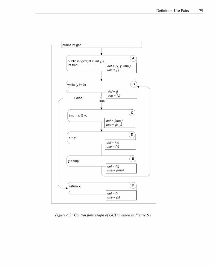
Definition-Use Pairs 79
public int gcd(int x, int y) {int tmp;
tmp = x % y;
while (y != 0){
True
return x;}
x = y;
y = tmp;
public int gcd
A
C
B
D
E
F
False
def = {x, y, tmp }use = { }
def = {}use = {y}
def = {tmp }use = {x, y}
def = { x}use = {y}
def = {y}use = {tmp}
def = {}use = {x}
Figure 6.2: Control flow graph of GCD method in Figure 6.1.

80 Dependence and Data Flow Models
public int gcd(int x, int y) {int tmp;
tmp = x % y;
y
return x;}
x = y;
A
C
D
F
xy yx
ytmp
y y
x
yy = tmp; E
while (y != 0){
B
Figure 6.3: Data dependence graph of GCD method in Figure 6.1, with nodes forstatements corresponding to the control flow graph in Figure 6.2. Each directed edgerepresents a direct data dependence, and the edge label indicates the variable thattransmits a value from the definition at the head of the edge to the use at the tail of theedge.
method. The control dependence graph shows direct control dependencies, that is,where execution of one statement controls whether another is executed. For example,execution of the body of a loop or if statement depends on the result of a predicate.
Control dependence differs from the sequencing information captured in the controlflow graph. The control flow graph imposes a definite order on execution even whentwo statements are logically independent and could be executed in either order with thesame results. If a statement is control- or data-dependent on another, then their orderof execution is not arbitrary. Program dependence representations typically includeboth data dependence and control dependence information in a single graph with thetwo kinds of information appearing as different kinds of edges among the same set ofnodes.
A node in the control flow graph that is reached on every execution path from entrypoint to exit is control dependent only on the entry point. For any other node N, reachedon some but not all execution paths, there is some branch that controls execution of N inthe sense that, depending on which way execution proceeds from the branch, executionof N either does or does not become inevitable. It is this notion of control that controldependence captures.
The notion of dominators in a rooted, directed graph can be used to make this∆ dominator
intuitive notion of “controlling decision” precise. Node M dominates node N if everypath from the root of the graph to N passes through M. A node will typically havemany dominators, but except for the root, there is a unique immediate dominator of∆ immediate
dominator node N, which is closest to N on any path from the root and which is in turn dominated
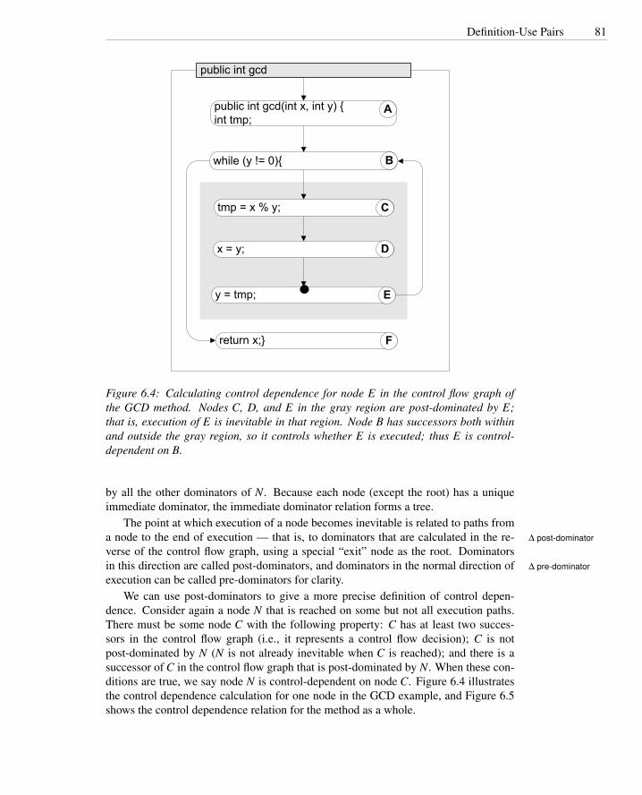
Definition-Use Pairs 81
public int gcd(int x, int y) {int tmp;
while (y != 0){
return x;}
public int gcd
A
B
F
tmp = x % y;
x = y;
y = tmp;
C
D
E
Figure 6.4: Calculating control dependence for node E in the control flow graph ofthe GCD method. Nodes C, D, and E in the gray region are post-dominated by E;that is, execution of E is inevitable in that region. Node B has successors both withinand outside the gray region, so it controls whether E is executed; thus E is control-dependent on B.
by all the other dominators of N. Because each node (except the root) has a uniqueimmediate dominator, the immediate dominator relation forms a tree.
The point at which execution of a node becomes inevitable is related to paths froma node to the end of execution — that is, to dominators that are calculated in the re- ∆ post-dominator
verse of the control flow graph, using a special “exit” node as the root. Dominatorsin this direction are called post-dominators, and dominators in the normal direction of ∆ pre-dominator
execution can be called pre-dominators for clarity.We can use post-dominators to give a more precise definition of control depen-
dence. Consider again a node N that is reached on some but not all execution paths.There must be some node C with the following property: C has at least two succes-sors in the control flow graph (i.e., it represents a control flow decision); C is notpost-dominated by N (N is not already inevitable when C is reached); and there is asuccessor of C in the control flow graph that is post-dominated by N. When these con-ditions are true, we say node N is control-dependent on node C. Figure 6.4 illustratesthe control dependence calculation for one node in the GCD example, and Figure 6.5shows the control dependence relation for the method as a whole.

82 Dependence and Data Flow Models
public int gcd(int x, int y) {int tmp;
tmp = x % y;
return x;}
x = y;
A
C
D
F
y = tmp; E
while (y != 0){
B
Figure 6.5: Control dependence tree of the GCD method. The loop test and the returnstatement are reached on every possible execution path, so they are control-dependentonly on the entry point. The statements within the loop are control-dependent on theloop test.
6.2 Data Flow Analysis
Definition-use pairs can be defined in terms of paths in the program control flow graph.As we have seen in the former section, there is an association (d,u) between a definitionof variable v at d and a use of variable v at u if and only if there is at least one controlflow path from d to u with no intervening definition of v. We also say that definition∆ reaching definition
vd reaches u, and that vd is a reaching definition at u. If, on the other hand, a controlflow path passes through another definition e of the same variable v, we say that ve killsvd at that point.
It would be possible to compute definition-use pairs by searching the control flowgraph for individual paths of the form described above. However, even if we consideronly loop-free paths, the number of paths in a graph can be exponentially larger thanthe number of nodes and edges. Practical algorithms therefore cannot search everyindividual path. Instead, they summarize the reaching definitions at a node over all thepaths reaching that node.
An efficient algorithm for computing reaching definitions (and several other prop-erties, as we will see below) is based on the way reaching definitions at one node arerelated to reaching definitions at an adjacent node. Suppose we are calculating thereaching definitions of node n, and there is an edge (p,n) from an immediate predeces-sor node p. We observe:
• If the predecessor node p can assign a value to variable v, then the definition vpreaches n. We say the definition vp is generated at p.
• If a definition vd of variable v reaches a predecessor node p, and if v is notredefined at that node (in which case we say the vd is killed at that point), thenthe definition is propagated on from p to n.

Data Flow Analysis 83
These observations can be stated in the form of an equation describing sets of reach-ing definitions. For example, reaching definitions at node E in Figure 6.2 are those atnode D, except that D adds a definition of y and replaces (kills) an earlier definition ofy:
Reach(E) = (Reach(D)\{xA})∪{xD}
This rule can be broken down into two parts to make it a little more intuitive andmore efficient to implement. The first part describes how node E receives values fromits predecessor D, and the second describes how it modifies those values for its succes-sors:
Reach(E) = ReachOut(D)ReachOut(D) = (Reach(D)\{xA})∪{xD}
In this form, we can easily express what should happen at the head of the whileloop (node B in Figure 6.2), where values may be transmitted both from the beginningof the procedure (node A) and through the end of the body of the loop (node E). Thebeginning of the procedure (node A) is treated as an initial definition of parametersand local variables. (If a local variable is declared but not initialized, it is treated as adefinition to the special value “uninitialized.”)
Reach(B) = ReachOut(A)∪ReachOut(E)ReachOut(A) = gen(A) = {xA,yA, tmpA}ReachOut(E) = (ReachIn(E)\{yA})∪{yE}
In general, for any node n with predecessors pred(n),
Reach(n) =⋃
m∈pred(n)
ReachOut(m)
ReachOut(n) = (ReachIn(n)\ kill(n))∪gen(n)
Remarkably, the reaching definitions can be calculated simply and efficiently, firstinitializing the reaching definitions at each node in the control flow graph to the emptyset, and then applying these equations repeatedly until the results stabilize. The algo-rithm is given as pseudocode in Figure 6.6.

84 Dependence and Data Flow Models
Algorithm Reaching definitions
Input: A control flow graph G = (nodes,edges)pred(n) = {m ∈ nodes | (m,n) ∈ edges}succ(m) = {n ∈ nodes | (m,n) ∈ edges}gen(n) = {vn} if variable v is defined at n, otherwise {}kill(n) = all other definitions of v if v is defined at n, otherwise {}
Output: Reach(n) = the reaching definitions at node n
for n ∈ nodes loopReachOut(n) = {} ;
end loop;
workList = nodes ;while (workList 6= {}) loop
// Take a node from worklist (e.g., pop from stack or queue)n = any node in workList ;workList = workList\{n} ;
oldVal = ReachOut(n) ;
// Apply flow equations, propagating values from predecessarsReach(n) =
⋃m∈pred(n)ReachOut(m);
ReachOut(n) = (Reach(n)\ kill(n))∪gen(n) ;
if ( ReachOut(n) 6= oldVal ) then// Propagate changed value to successor nodesworkList = workList∪ succ(n)
end if;end loop;
Figure 6.6: An iterative work-list algorithm to compute reaching definitions by apply-ing each flow equation until the solution stabilizes.

Classic Analyses: Live and Avail 85
6.3 Classic Analyses: Live and Avail
Reaching definition is a classic data flow analysis adapted from compiler constructionto applications in software testing and analysis. Other classical data flow analysesfrom compiler construction can likewise be adapted. Moreover, they follow a commonpattern that can be used to devise a wide variety of additional analyses.
Available expressions is another classical data flow analysis, used in compiler con-struction to determine when the value of a subexpression can be saved and reused ratherthan recomputed. This is permissible when the value of the subexpression remains un-changed regardless of the execution path from the first computation to the second.
Available expressions can be defined in terms of paths in the control flow graph. Anexpression is available at a point if, for all paths through the control flow graph fromprocedure entry to that point, the expression has been computed and not subsequentlymodified. We say an expression is generated (becomes available) where it is computedand is killed (ceases to be available) when the value of any part of it changes (e.g.,when a new value is assigned to a variable in the expression).
As with reaching definitions, we can obtain an efficient analysis by describing therelation between the available expressions that reach a node in the control flow graphand those at adjacent nodes. The expressions that become available at each node (thegen set) and the expressions that change and cease to be available (the kill set) can becomputed simply, without consideration of control flow. Their propagation to a nodefrom its predecessors is described by a pair of set equations:
Avail(n) =⋂
m∈pred(n)
AvailOut(m)
AvailOut(n) = (Avail(n)\ kill(n))∪Gen(n)
The similarity to the set equations for reaching definitions is striking. Both propa-gate sets of values along the control flow graph in the direction of program execution(they are forward analyses), and both combine sets propagated along different control forward analysis
flow paths. However, reaching definitions combines propagated sets using set union,since a definition can reach a use along any execution path. Available expressions com- any-path analysis
bines propagated sets using set intersection, since an expression is considered availableat a node only if it reaches that node along all possible execution paths. Thus we say all-paths analysis
that, while reaching definitions is a forward, any-path analysis, available expressionsis a forward, all-paths analysis. A work-list algorithm to implement available expres-sions analysis is nearly identical to that for reaching definitions, except for initializationand the flow equations, as shown in Figure 6.7.
Applications of a forward, all-paths analysis extend beyond the common subexpres-sion detection for which the Avail algorithm was originally developed. We can thinkof available expressions as tokens that are propagated from where they are generatedthrough the control flow graph to points where they might be used. We obtain differentanalyses by choosing tokens that represent some other property that becomes true (isgenerated) at some points, may become false (be killed) at some other points, and is

86 Dependence and Data Flow Models
Algorithm Available expressions
Input: A control flow graph G = (nodes,edges), with a distinguished root node start.pred(n) = {m ∈ nodes | (m,n) ∈ edges}succ(m) = {n ∈ nodes | (m,n) ∈ edges}gen(n) = all expressions e computed at node nkill(n) = expressions e computed anywhere, whose value is changed at n;
kill(start) is the set of all e.
Output: Avail(n) = the available expressions at node n
for n ∈ nodes loopAvailOut(n) = set of all e defined anywhere ;
end loop;
workList = nodes ;while (workList 6= {}) loop
// Take a node from worklist (e.g., pop from stack or queue)n = any node in workList ;workList = workList\{n} ;
oldVal = AvailOut(n) ;
// Apply flow equations, propagating values from predecessorsAvail(n) =
⋂m∈pred(n)AvailOut(m);
AvailOut(n) = (Avail(n)\ kill(n))∪gen(n) ;
if ( AvailOut(n) 6= oldVal ) then// Propagate changes to successorsworkList = workList∪ succ(n)
end if;end loop;
Figure 6.7: An iterative work-list algorithm for computing available expressions.

Classic Analyses: Live and Avail 87
1 /** A trivial method with a potentially uninitialized variable.2 * Java compilers reject the program. The compiler uses3 * data flow analysis to determine that there is a potential4 * (syntactic) execution path on which k is used before it5 * has been assigned an initial value.6 */7 static void questionable() {8 int k;9 for (int i=0; i < 10; ++i) {
10 if (someCondition(i)) {11 k = 0;12 } else {13 k += i;14 }15 }16 System.out.println(k);17 }18 }
Figure 6.8: Function questionable (repeated from Chapter 3) has a potentially unini-tialized variable, which the Java compiler can detect using data flow analysis.
evaluated (used) at certain points in the graph. By associating appropriate sets of tokensin gen and kill sets for a node, we can evaluate other properties that fit the pattern
“G occurs on all execution paths leading to U, and there is no interveningoccurrence of K between the last occurrence of G and U.”
G, K, and U can be any events we care to check, so long as we can mark their occur-rences in a control flow graph.
An example problem of this kind is variable initialization. We noted in Chapter 3that Java requires a variable to be initialized before use on all execution paths. Theanalysis that enforces this rule is an instance of Avail. The tokens propagated throughthe control flow graph record which variables have been assigned initial values. Sincethere is no way to “uninitialize” a variable in Java, the kill sets are empty. Figure 6.8repeats the source code of an example program from Chapter 3. The correspondingcontrol flow graph is shown with definitions and uses in Figure 6.9 and annotated withgen and kill sets for the initialized variable check in Figure 6.10.
Reaching definitions and available expressions are forward analyses; that is, theypropagate values in the direction of program execution. Given a control flow graphmodel, it is just as easy to propagate values in the opposite direction, backward from backward
analysisnodes that represent the next steps in computation. Backward analyses are useful fordetermining what happens after an event of interest. Live variables is a backwardanalysis that determines whether the value held in a variable may be subsequently
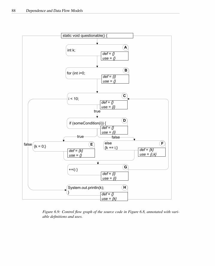
88 Dependence and Data Flow Models
int k;
i < 10;
for (int i=0;
++i) }
true
if (someCondition(i)) {
else {k += i;}
static void questionable() {
A
C
B
D
F
G
def = {}use = {}
def = {i}use = {}
def = {}use = {i}
def = {}use = {i}
def = {k}use = {i,k}
def = {i}use = {i}
{k = 0;} Edef = {k}use = {}
falsetrue
false
System.out.println(k);}
H
def = {}use = {k}
Figure 6.9: Control flow graph of the source code in Figure 6.8, annotated with vari-able definitions and uses.

Classic Analyses: Live and Avail 89
int k;
i < 10;
for (int i=0;
++i) }
true
if (someCondition(i)) {
else {k += i;}
static void questionable() {
A
C
B
D
F
G
gen = {i}
gen = {k}{k = 0;} E
gen = {k}
falsetrue
false
System.out.println(k);}
H
kill = {i,k}
gen = {i}
Figure 6.10: Control flow graph of the source code in Figure 6.8, annotated with genand kill sets for checking variable initialization using a forward, all-paths Avail anal-ysis. (Empty gen and kill sets are omitted.) The Avail set flowing from node G to nodeC will be {i,k}, but the Avail set flowing from node B to node C is {i}. The all-pathsanalysis intersects these values, so the resulting Avail(C) is {i}. This value propagatesthrough nodes C and D to node F, which has a use of k as well as a definition. Sincek 6∈ Avail(F), a possible use of an uninitialized variable is detected.

90 Dependence and Data Flow Models
used. Because a variable is considered live if there is any possible execution path onwhich it is used, a backward, any-path analysis is used.
A variable is live at a point in the control flow graph if, on some execution path, itscurrent value may be used before it is changed. Live variables analysis can be expressedas set equations as before. Where Reach and Avail propagate values to a node from itspredecessors, Live propagates values from the successors of a node. The gen sets arevariables used at a node, and the kill sets are variables whose values are replaced. Setunion is used to combine values from adjacent nodes, since a variable is live at a nodeif it is live at any of the succeeding nodes.
Live(n) =⋃
m∈succ(n)
LiveOut(m)
LiveOut(n) = (Live(n)\ kill(n))∪Gen(n)
These set equations can be implemented using a work-list algorithm analogousto those already shown for reaching definitions and available expressions, except thatsuccessor edges are followed in place of predecessors and vice versa.
Like available expressions analysis, live variables analysis is of interest in testingand analysis primarily as a pattern for recognizing properties of a certain form. Abackward, any-paths analysis allows us to check properties of the following form:
“After D occurs, there is at least one execution path on which G occurswith no intervening occurrence of K.”
Again we choose tokens that represent properties, using gen sets to mark occurrencesof G events (where a property becomes true) and kill sets to mark occurrences of Kevents (where a property ceases to be true).
One application of live variables analysis is to recognize useless definitions, thatis, assigning a value that can never be used. A useless definition is not necessarily aprogram error, but is often symptomatic of an error. In scripting languages like Perl andPython, which do not require variables to be declared before use, a useless definitiontypically indicates that a variable name has been misspelled, as in the common gatewayinterface (CGI) script of Figure 6.11.
We have so far seen a forward, any-path analysis (reaching definitions), a forward,all-paths analysis (available definitions), and a backward, any-path analysis (live vari-ables). One might expect, therefore, to round out the repertoire of patterns with abackward, all-paths analysis, and this is indeed possible. Since there is no classicalname for this combination, we will call it “inevitability” and use it for properties of theform
“After D occurs, G always occurs with no intervening occurrence of K”
or, informally,
“D inevitably leads to G before K”
Examples of inevitability checks might include ensuring that interrupts are reenabledafter executing an interrupt-handling routine in low-level code, files are closed afteropening them, and so on.

From Execution to Conservative Flow Analysis 91
1 class SampleForm(FormData):2 """ Used with Python cgi module3 to hold and validate data4 from HTML form """5
6 fieldnames = (’name’, ’email’, ’comment’)7
8 # Trivial example of validation. The bug would be9 # harder to see in a real validation method.
10 def validate(self):11 valid = 1;12 if self.name == "" : valid = 013 if self.email == "" : vald = 014 if self.comment == "" : valid = 015 return valid
Figure 6.11: Part of a CGI program (Web form processing) in Python. The misspelledvariable name in the data validation method will be implicitly declared and will notbe rejected by the Python compiler or interpreter, which could allow invalid data tobe treated as valid. The classic live variables data flow analysis can show that theassignment to valid is a useless definition, suggesting that the programmer probablyintended to assign the value to a different variable.
6.4 From Execution to Conservative Flow Analysis
Data flow analysis algorithms can be thought of as a kind of simulated execution. Inplace of actual values, much smaller sets of possible values are maintained (e.g., asingle bit to indicate whether a particular variable has been initialized). All possibleexecution paths are considered at once, but the number of different states is kept smallby associating just one summary state at each program point (node in the control flowgraph). Since the values obtained at a particular program point when it is reachedalong one execution path may be different from those obtained on another executionpath, the summary state must combine the different values. Considering flow analysisin this light, we can systematically derive a conservative flow analysis from a dynamic(that is, run-time) analysis.
As an example, consider the “taint-mode” analysis that is built into the program-ming language Perl. Taint mode is used to prevent some kinds of program errors thatresult from neglecting to fully validate data before using it, particularly where invali-dated data could present a security hazard. For example, if a Perl script wrote to a filewhose name was taken from a field in a Web form, a malicious user could provide a fullpath to sensitive files. Taint mode detects and prevents use of the “tainted” Web forminput in a sensitive operation like opening a file. Other languages used in CGI scriptsdo not provide such a monitoring function, but we will consider how an analogousstatic analysis could be designed for a programming language like C.

92 Dependence and Data Flow Models
When Perl is running in taint mode, it tracks the sources from which each variablevalue was derived, and distinguishes between safe and tainted data. Tainted data is anyinput (e.g., from a Web form) and any data derived from tainted data. For example,if a tainted string is concatenated with a safe string, the result is a tainted string. Oneexception is that pattern matching always returns safe strings, even when matchingagainst tainted data — this reflects the common Perl idiom in which pattern matchingis used to validate user input. Perl’s taint mode will signal a program error if tainteddata is used in a potentially dangerous way (e.g., as a file name to be opened).
Perl monitors values dynamically, tagging data values and propagating the tagsthrough computation. Thus, it is entirely possible that a Perl script might run with-out errors in testing, but an unanticipated execution path might trigger a taint modeprogram error in production use. Suppose we want to perform a similar analysis, butinstead of checking whether “tainted” data is used unsafely on a particular execution,we want to ensure that tainted data can never be used unsafely on any execution. Wemay also wish to perform the analysis on a language like C, for which run-time taggingis not provided and would be expensive to add. So, we can consider deriving a conser-vative, static analysis that is like Perl’s taint mode except that it considers all possibleexecution paths.
A data flow analysis for taint would be a forward, any-path analysis with tokensrepresenting tainted variables. The gen set at a program point would be a set containingany variable that is assigned a tainted value at that point. Sets of tainted variables wouldbe propagated forward to a node from its predecessors, with set union where a node inthe control flow graph has more than one predecessor (e.g., the head of a loop).
There is one fundamental difference between such an analysis and the classic dataflow analyses we have seen so far: The gen and kill sets associated with a programpoint are not constants. Whether or not the value assigned to a variable is tainted (andthus whether the variable belongs in the gen set or in the kill set) depends on the setof tainted variables at that program point, which will vary during the course of theanalysis.
There is a kind of circularity here — the gen set and kill set depend on the set oftainted variables, and the set of tainted variables may in turn depend on the gen and killset. Such circularities are common in defining flow analyses, and there is a standardapproach to determining whether they will make the analysis unsound. To convinceourselves that the analysis is sound, we must show that the output values computed byeach flow equation are monotonically increasing functions of the input values. We willsay more precisely what “increasing” means below.
The determination of whether a computed value is tainted will be a simple functionof the set of tainted variables at a program point. For most operations of one or morearguments, the output is tainted if any of the inputs are tainted. As in Perl, we maydesignate one or a few operations (operations used to check an input value for validity)as taint removers. These special operations always return an untainted value regardlessof their inputs.
Suppose we evaluate the taintedness of an expression with the input set of taintedvariables being {a,b}, and again with the input set of tainted variables being {a,b,c}.Even without knowing what the expression is, we can say with certainty that if theexpression is tainted in the first evaluation, it must also be tainted in the second evalu-
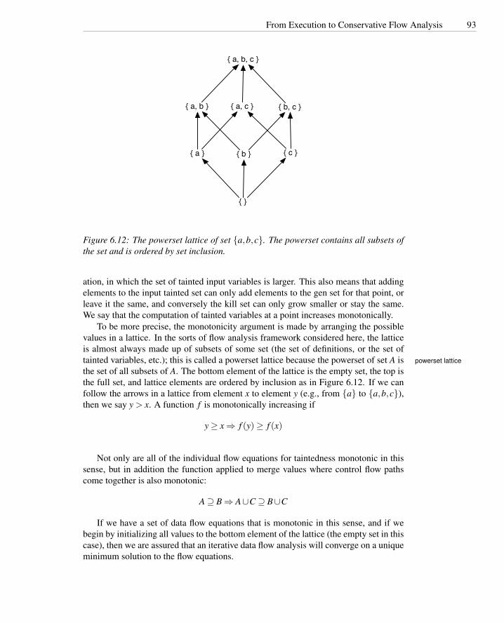
From Execution to Conservative Flow Analysis 93
{ a, b, c }
{ a, b } { a, c } { b, c }
{ a } { b } { c }
{ }
Figure 6.12: The powerset lattice of set {a,b,c}. The powerset contains all subsets ofthe set and is ordered by set inclusion.
ation, in which the set of tainted input variables is larger. This also means that addingelements to the input tainted set can only add elements to the gen set for that point, orleave it the same, and conversely the kill set can only grow smaller or stay the same.We say that the computation of tainted variables at a point increases monotonically.
To be more precise, the monotonicity argument is made by arranging the possiblevalues in a lattice. In the sorts of flow analysis framework considered here, the latticeis almost always made up of subsets of some set (the set of definitions, or the set oftainted variables, etc.); this is called a powerset lattice because the powerset of set A is powerset lattice
the set of all subsets of A. The bottom element of the lattice is the empty set, the top isthe full set, and lattice elements are ordered by inclusion as in Figure 6.12. If we canfollow the arrows in a lattice from element x to element y (e.g., from {a} to {a,b,c}),then we say y > x. A function f is monotonically increasing if
y ≥ x ⇒ f (y)≥ f (x)
Not only are all of the individual flow equations for taintedness monotonic in thissense, but in addition the function applied to merge values where control flow pathscome together is also monotonic:
A ⊇ B ⇒ A∪C ⊇ B∪C
If we have a set of data flow equations that is monotonic in this sense, and if webegin by initializing all values to the bottom element of the lattice (the empty set in thiscase), then we are assured that an iterative data flow analysis will converge on a uniqueminimum solution to the flow equations.

94 Dependence and Data Flow Models
The standard data flow analyses for reaching definitions, live variables, and avail-able expressions can all be justified in terms of powerset lattices. In the case of availableexpressions, though, and also in the case of other all-paths analyses such as the one wehave called “inevitability,” the lattice must be flipped over, with the empty set at the topand the set of all variables or propositions at the bottom. (This is why we used the setof all tokens, rather than the empty set, to initialize the Avail sets in Figure 6.7.)
6.5 Data Flow Analysis with Arrays and Pointers
The models and flow analyses described in the preceding section have been limitedto simple scalar variables in individual procedures. Arrays and pointers (includingobject references and procedure arguments) introduce additional issues, because it isnot possible in general to determine whether two accesses refer to the same storagelocation. For example, consider the following code fragment:
1 a[i] = 13;2 k = a[j];
Are these two lines a definition-use pair? They are if the values of i and j are equal,which might be true on some executions and not on others. A static analysis cannot, ingeneral, determine whether they are always, sometimes, or never equal, so a source ofimprecision is necessarily introduced into data flow analysis.
Pointers and object references introduce the same issue, often in less obvious ways.Consider the following snippet:
1 a[2] = 42;2 i = b[2];
It seems that there cannot possibly be a definition-use pair involving these twolines, since they involve none of the same variables. However, arrays in Java are dy-namically allocated objects accessed through pointers. Pointers of any kind introducethe possibility of aliasing, that is, of two different names referring to the same stor-age location. For example, the two lines above might have been part of the followingprogram fragment:
1 int [ ] a = new int[3];2 int [ ] b = a;3 a[2] = 42;4 i = b[2];
Here a and b are aliases, two different names for the same dynamically allocated∆ alias
array object, and an assignment to part of a is also an assignment to part of b.The same phenomenon, and worse, appears in languages with lower-level pointer
manipulation. Perhaps the most egregious example is pointer arithmetic in C:1 p = &b;2 *(p + i) = k;

Data Flow Analysis with Arrays and Pointers 95
It is impossible to know which variable is defined by the second line. Even ifwe know the value of i, the result is dependent on how a particular compiler arrangesvariables in memory.
Dynamic references and the potential for aliasing introduce uncertainty into dataflow analysis. In place of a definition or use of a single variable, we may have apotential definition or use of a whole set of variables or locations that could be aliasesof each other. The proper treatment of this uncertainty depends on the use to whichthe analysis will be put. For example, if we seek strong assurance that v is alwaysinitialized before it is used, we may not wish to treat an assignment to a potential aliasof v as initialization, but we may wish to treat a use of a potential alias of v as a use ofv.
A useful mental trick for thinking about treatment of aliases is to translate the un-certainty introduced by aliasing into uncertainty introduced by control flow. After all,data flow analysis already copes with uncertainty about which potential execution pathswill actually be taken; an infeasible path in the control flow graph may add elementsto an any-paths analysis or remove results from an all-paths analysis. It is usually ap-propriate to treat uncertainty about aliasing consistently with uncertainty about controlflow. For example, considering again the first example of an ambiguous reference:
1 a[i] = 13;2 k = a[j];
We can imagine replacing this by the equivalent code:1 a[i] = 13;2 if (i == j) {3 k = a[i];4 } else {5 k = a[j];6 }
In the (imaginary) transformed code, we could treat all array references as distinct,because the possibility of aliasing is fully expressed in control flow. Now, if we areusing an any-path analysis like reaching definitions, the potential aliasing will resultin creating a definition-use pair. On the other hand, an assignment to a[j] would notkill a previous assignment to a[i]. This suggests that, for an any-path analysis, gen setsshould include everything that might be referenced, but kill sets should include onlywhat is definitely referenced.
If we were using an all-paths analysis, like available expressions, we would obtaina different result. Because the sets of available expressions are intersected where con-trol flow merges, a definition of a[i] would make only that expression, and none of itspotential aliases, available. On the other hand, an assignment to a[j] would kill a[i]. Thissuggests that, for an all-paths analysis, gen sets should include only what is definitelyreferenced, but kill sets should include all the possible aliases.
Even in analysis of a single procedure, the effect of other procedures must be con-sidered at least with respect to potential aliases. Consider, for example, this fragmentof a Java method:

96 Dependence and Data Flow Models
1 public void transfer (CustInfo fromCust, CustInfo toCust) {2
3 PhoneNum fromHome = fromCust.gethomePhone();4 PhoneNum fromWork = fromCust.getworkPhone();5
6 PhoneNum toHome = toCust.gethomePhone();7 PhoneNum toWork = toCust.getworkPhone();
We cannot determine whether the two arguments fromCust and toCust are refer-ences to the same object without looking at the context in which this method is called.Moreover, we cannot determine whether fromHome and fromWork are (or could be)references to the same object without more information about how CustInfo objects aretreated elsewhere in the program.
Sometimes it is sufficient to treat all nonlocal information as unknown. For ex-ample, we could treat the two CustInfo objects as potential aliases of each other, andsimilarly treat the four PhoneNum objects as potential aliases. Sometimes, though,large sets of aliases will result in analysis results that are so imprecise as to be use-less. Therefore data flow analysis is often preceded by an interprocedural analysis tocalculate sets of aliases or the locations that each pointer or reference can refer to.
6.6 Interprocedural Analysis
Most important program properties involve more than one procedure, and as mentionedearlier, some interprocedural analysis (e.g., to detect potential aliases) is often requiredas a prelude even to intraprocedural analysis. One might expect the interproceduralanalysis and models to be a natural extension of the intraprocedural analysis, followingprocedure calls and returns like intraprocedural control flow. Unfortunately, this isseldom a practical option.
If we were to extend data flow models by following control flow paths throughprocedure calls and returns, using the control flow graph model and the call graphmodel together in the obvious way, we would observe many spurious paths. Figure 6.13illustrates the problem: Procedure foo and procedure bar each make a call on proceduresub. When procedure call and return are treated as if they were normal control flow, inaddition to the execution sequences (A,X ,Y,B) and (C,X ,Y,D), the combined graphcontains the impossible paths (A,X ,Y,D) and (C,X ,Y,B).
It is possible to represent procedure calls and returns precisely, for example bymaking a copy of the called procedure for each point at which it is called. This wouldresult in a context-sensitive analysis. The shortcoming of context sensitive analysiscontext-sensitive
analysis was already mentioned in the previous chapter: The number of different contexts inwhich a procedure must be considered could be exponentially larger than the numberof procedures. In practice, a context-sensitive analysis can be practical for a smallgroup of closely related procedures (e.g., a single Java class), but is almost never apractical option for a whole program.
Some interprocedural properties are quite independent of context and lend them-selves naturally to analysis in a hierarchical, piecemeal fashion. Such a hierarchical

Interprocedural Analysis 97
A
B
sub(...)
Foo()
callreturn
bar(
C
D
sub(...)
bar()
callreturnX
Y
sub()
Figure 6.13: Spurious execution paths result when procedure calls and returns aretreated as normal edges in the control flow graph. The path (A,X ,Y,D) appears in thecombined graph, but it does not correspond to an actual execution order.
analysis can be both precise and efficient. The analyses that are provided as part ofnormal compilation are often of this sort. The unhandled exception analysis of Java isa good example: Each procedure (method) is required to declare the exceptions that itmay throw without handling. If method M calls method N in the same or another class,and if N can throw some exception, then M must either handle that exception or de-clare that it, too, can throw the exception. This analysis is simple and efficient because,when analyzing method M, the internal structure of N is irrelevant; only the results ofthe analysis at N (which, in Java, is also part of the signature of N) are needed.
Two conditions are necessary to obtain an efficient, hierarchical analysis like the ex-ception analysis routinely carried out by Java compilers. First, the information neededto analyze a calling procedure must be small: It must not be proportional either to thesize of the called procedure, or to the number of procedures that are directly or in-directly called. Second, it is essential that information about the called procedure beindependent of the caller; that is, it must be context-independent. When these two con-ditions are true, it is straightforward to develop an efficient analysis that works upwardfrom leaves of the call graph. (When there are cycles in the call graph from recursiveor mutually recursive procedures, an iterative approach similar to data flow analysisalgorithms can usually be devised.)
Unfortunately, not all important properties are amenable to hierarchical analysis.Potential aliasing information, which is essential to data flow analysis even within in-dividual procedures, is one of those that are not. We have seen that potential aliasingcan depend in part on the arguments passed to a procedure, so it does not have thecontext-independence property required for an efficient hierarchical analysis. For suchan analysis, additional sacrifices of precision must be made for the sake of efficiency.
Even when a property is context-dependent, an analysis for that property may becontext-insensitive, although the context-insensitive analysis will necessarily be lessprecise as a consequence of discarding context information. At the extreme, a lineartime analysis can be obtained by discarding both context and control flow information.
flow-insensitive
Context- and flow-insensitive algorithms for pointer analysis typically treat each

98 Dependence and Data Flow Models
statement of a program as a constraint. For example, on encountering an assignment1 x = y;
where y is a pointer, such an algorithm simply notes that x may refer to any of thesame objects that y may refer to. References(x) ⊇ References(y) is a constraint that iscompletely independent of the order in which statements are executed. A procedurecall, in such an analysis, is just an assignment of values to arguments. Using efficientdata structures for merging sets, some analyzers can process hundreds of thousands oflines of source code in a few seconds. The results are imprecise, but still much betterthan the worst-case assumption that any two compatible pointers might refer to thesame object.
The best approach to interprocedural pointer analysis will often lie somewhere be-tween the astronomical expense of a precise, context- and flow-sensitive pointer anal-ysis and the imprecision of the fastest context- and flow-insensitive analyses. Unfor-tunately, there is not one best algorithm or tool for all uses. In addition to context andflow sensitivity, important design trade-offs include the granularity of modeling refer-ences (e.g., whether individual fields of an object are distinguished) and the granularityof modeling the program heap (that is, which allocated objects are distinguished fromeach other).
Summary
Data flow models are used widely in testing and analysis, and the data flow analysisalgorithms used for deriving data flow information can be adapted to additional uses.The most fundamental model, complementary to models of control flow, represents theways values can flow from the points where they are defined (computed and stored) topoints where they are used.
Data flow analysis algorithms efficiently detect the presence of certain patterns inthe control flow graph. Each pattern involves some nodes that initiate the pattern andsome that conclude it, and some nodes that may interrupt it. The name “data flowanalysis” reflects the historical development of analyses for compilers, but patternsmay be used to detect other control flow patterns.
An any-path analysis determines whether there is any control flow path from theinitiation to the conclusion of a pattern without passing through an interruption. An all-paths analysis determines whether every path from the initiation necessarily reaches aconcluding node without first passing through an interruption. Forward analyses checkfor paths in the direction of execution, and backward analyses check for paths in theopposite direction. The classic data flow algorithms can all be implemented usingsimple work-list algorithms.
A limitation of data flow analysis, whether for the conventional purpose or to checkother properties, is that it cannot distinguish between a path that can actually be exe-cuted and a path in the control flow graph that cannot be followed in any execution. Arelated limitation is that it cannot always determine whether two names or expressionsrefer to the same object.
Fully detailed data flow analysis is usually limited to individual procedures or a fewclosely related procedures (e.g., a single class in an object-oriented program). Analyses

Interprocedural Analysis 99
that span whole programs must resort to techniques that discard or summarize someinformation about calling context, control flow, or both. If a property is independentof calling context, a hierarchical analysis can be both precise and efficient. Potentialaliasing is a property for which calling context is significant. There is therefore a trade-off between very fast but imprecise alias analysis techniques and more precise but muchmore expensive techniques.
Further Reading
Data flow analysis techniques were originally developed for compilers, as a systematicway to detect opportunities for code-improving transformations and to ensure that thosetransformations would not introduce errors into programs (an all-too-common experi-ence with early optimizing compilers). The compiler construction literature remainsan important source of reference information for data flow analysis, and the classic“Dragon Book” text [ASU86] is a good starting point.
Fosdick and Osterweil recognized the potential of data flow analysis to detect pro-gram errors and anomalies that suggested the presence of errors more than two decadesago [FO76]. While the classes of data flow anomaly detected by Fosdick and Oster-weil’s system has largely been obviated by modern strongly typed programming lan-guages, they are still quite common in modern scripting and prototyping languages.Olender and Osterweil later recognized that the power of data flow analysis algo-rithms for recognizing execution patterns is not limited to properties of data flow,and developed a system for specifying and checking general sequencing properties[OO90, OO92].
Interprocedural pointer analyses — either directly determining potential aliasing re-lations, or deriving a “points-to” relation from which aliasing relations can be derived— remains an area of active research. At one extreme of the cost-versus-precisionspectrum of analyses are completely context- and flow-insensitive analyses like thosedescribed by Steensgaard [Ste96]. Many researchers have proposed refinements thatobtain significant gains in precision at small costs in efficiency. An important direc-tion for future work is obtaining acceptably precise analyses of a portion of a largeprogram, either because a whole program analysis cannot obtain sufficient precision atacceptable cost or because modern software development practices (e.g., incorporatingexternally developed components) mean that the whole program is never available inany case. Rountev et al. present initial steps toward such analyses [RRL99]. A veryreadable overview of the state of the art and current research directions (circa 2001) isprovided by Hind [Hin01].

100 Dependence and Data Flow Models
Exercises
6.1. For a graph G = (N,V ) with a root r ∈N, node m dominates node n if every pathfrom r to n passes through m. The root node is dominated only by itself.
The relation can be restated using flow equations.
(a) When dominance is restated using flow equations, will it be stated in theform of an any-path problem or an all-paths problem? Forward or back-ward? What are the tokens to be propagated, and what are the gen and killsets?
(b) Give a flow equation for Dom(n).
(c) If the flow equation is solved using an iterative data flow analysis, whatshould the set Dom(n) be initialized to at each node n?
(d) Implement an iterative solver for the dominance relation in a programminglanguage of your choosing.
The first line of input to your program is an integer between 1 and 100 in-dicating the number k of nodes in the graph. Each subsequent line of inputwill consist of two integers, m and n, representing an edge from node mto node n. Node 0 designates the root, and all other nodes are designatedby integers between 0 and k− 1. The end of the input is signaled by thepseudo-edge (−1,−1).
The output of your program should be a sequences of lines, each containingtwo integers separated by blanks. Each line represents one edge of the Domrelation of the input graph.
(e) The Dom relation itself is not a tree. The immediate dominators relation isa tree. Write flow equations to calculate immediate dominators, and thenmodify the program from part (d) to compute the immediate dominancerelation.
6.2. Write flow equations for inevitability, a backward, all-paths intraprocedural anal-ysis. Event (or program point) q is inevitable at program point p if every execu-tion path from p to a normal exit point passes through q.
6.3. The Java language automatically initializes fields of objects, in contrast to localvariables of methods that the programmer is responsible for initializing. Givenwhat you know of intra- and interprocedural data flow analysis, explain why thelanguage designers may have made these design choices.
6.4. Show the data and control dependence graphs for the binary search program ofFigure 7.1 on page 103.

Chapter 7
Symbolic Execution andProof of Properties
Symbolic execution builds predicates that characterize the conditions under which ex-ecution paths can be taken and the effect of the execution on program state. Extractingpredicates through symbolic execution is the essential bridge from the complexity ofprogram behavior to the simpler and more orderly world of logic. It finds importantapplications in program analysis, in generating test data, and in formal verification1
(proofs) of program correctness.Conditions under which a particular control flow path is taken can be determined
through symbolic execution. This is useful for identifying infeasible program paths(those that can never be taken) and paths that could be taken when they should not. It isfundamental to generating test data to execute particular parts and paths in a program.
Deriving a logical representation of the effect of execution is essential in methodsthat compare a program’s possible behavior to a formal specification. We have notedin earlier chapters that proving the correctness of a program is seldom an achievable oruseful goal. Nonetheless the basic methods of formal verification, including symbolicexecution, underpin practical techniques in software analysis and testing. Symbolicexecution and the techniques of formal verification find use in several domains:
• Rigorous proofs of properties of (small) critical subsystems, such as a safetykernel of a medical device;
• Formal verification of critical properties (e.g., security properties) that are par-ticularly resistant to dynamic testing;
• Formal verification of algorithm descriptions and logical designs that are muchless complex than their implementations in program code.
1Throughout this book we use the term verification in the broad sense of checking whether a programor system is consistent with some form of specification. The broad sense of verification includes, for ex-ample, inspection techniques and program testing against informally stated specifications. The term formalverification is used in the scientific literature in a much narrower sense to denote techniques that construct amathematical proof of consistency between some formal representation of a program or design and a formalspecification.
101

102 Symbolic Execution and Proof of Properties
More fundamentally, the techniques of formal reasoning are a conceptual foundationfor a variety of analysis techniques, ranging from informal reasoning about programbehavior and correctness to automated checks for certain classes of errors.
7.1 Symbolic State and Interpretation
Tracing execution is familiar to any programmer who has attempted to understand thebehavior of source code by simulating execution. For example, one might trace asingle statement in the binary search routine of Figure 7.1 as shown on the left sideof Figure 7.2. One can just as easily use symbolic values like L and H in place ofconcrete values, as shown on the right side of Figure 7.2. Tracing execution withsymbolic values and expressions is the basis of symbolic execution.
When tracing execution with concrete values, it is clear enough what to do with abranch statement, for example, an if or while test: The test predicate is evaluated withthe current values, and the appropriate branch is taken. If the values bound to variablesare symbolic expressions, however, both the True and False outcomes of the decisionmay be possible. Execution can be traced through the branch in either direction, andexecution of the test is interpreted as adding a constraint to record the outcome. Forexample, consider
while (high >= low) {
Suppose the symbolic state after one loop iteration is
low = 0
∧ high = H−12 −1
∧ mid = H−12
If we trace execution of the test assuming a True outcome (leading to a seconditeration of the loop), the loop condition becomes a constraint in the symbolic stateimmediately after the while test:
low = 0
∧ high = H−12 −1
∧ mid = H−12
∧ H−12 −1 ≥ 0
Later, when we consider the branch assuming a False outcome of the test, the newconstraint is negated and becomes ¬(H−1
2 −1 ≥ 0) or, equivalently, H−12 −1 < 0.
Execution can proceed in this way down any path in the program. One can thinkof “satisfying” the predicate by finding concrete values for the symbolic variables thatmake it evaluate to True; this corresponds to finding data values that would force execu-tion of that program path. If no such satisfying values are possible, then that executionpath cannot be executed with any data values; we say it is an infeasible path.

Symbolic State and Interpretation 103
1
2 /** Binary search for key in sorted array dictKeys, returning3 * corresponding value from dictValues or null if key does4 * not appear in dictKeys. Standard binary search algorithm5 * as described in any elementary text on data structures and algorithms.6 **/7
8 char * binarySearch( char *key, char *dictKeys[ ], char *dictValues[ ],9 int dictSize) {
10
11 int low = 0;12 int high = dictSize - 1;13 int mid;14 int comparison;15
16 while (high >= low) {17 mid = (high + low) / 2;18 comparison = strcmp( dictKeys[mid], key );19 if (comparison < 0) {20 /* dictKeys[mid] too small; look higher */21 low = mid + 1;22 } else if ( comparison > 0 ) {23 /* dictKeys[mid] too large; look lower */24 high = mid - 1;25 } else {26 /* found */27 return dictValues[mid];28 }29 }30 return 0; /* null means not found */31 }32
Figure 7.1: Binary search procedure.

104 Symbolic Execution and Proof of Properties
beforelow 12high 15mid –
mid = (high + low) / 2;
afterlow 12high 15mid 13
beforelow Lhigh Hmid –
mid = (high + low) / 2;
afterlow L
high H
mid L+H2
Figure 7.2: Hand-tracing an execution step with concrete values (left) and symbolicvalues (right).
7.2 Summary Information
If there were only a finite number of execution paths in a program, then in principlea symbolic executor could trace each of them and obtain a precise representation of apredicate that characterizes each one. From even a few execution steps in the preced-ing small example, one can see that the representation of program state will quicklybecome unwieldy. Moreover, there are a potentially infinite number of program exe-cution paths to consider. An automated symbolic executor can cope with much morecomplex symbolic expressions than a human, but even an automated tool will not getfar with brute force evaluation of every program path.
Since the representation of program state is a logical predicate, there is an alterna-tive to keeping a complete representation of the state at every point: a weaker predicatecan always be substituted for the complete representation. That is, if the representationof the program state at some point in execution is P, and if W ⇒ P, then substitutingW for P will result in a predicate that still correctly describes the execution state, butwith less precision. We call W a summary of P.
Consider the computation of mid in line 17 of the binary search example fromFigure 7.1. If we are reasoning about the performance of binary search, the fact thatthe value of mid lies halfway between the values of low and high is important, but ifwe are reasoning about functional correctness it matters only that mid lies somewherebetween them. Thus, if we had low = L∧high = H ∧mid = M, and if we could showL ≤ H, we could replace M = (L+H)/2 by the weaker condition L ≤ M ≤ H.
Note that the weaker predicate L ≤ mid ≤ H is chosen based on what must betrue for the program to execute correctly. This is not information that can be derivedautomatically from source code; it depends as well on our understanding of the codeand our rationale for believing it to be correct. A predicate stating what should be trueat a given point can be expressed in the form of an assertion. When we assert thatpredicate W is true at a point in a program, we mark our intention both to verify it atthat point (by showing that W is implied by the predicates that describe the programstate at that point) and to replace part of the program state description P by W at that
Loops and Assertions 105
point.One of the prices of weakening the predicate in this way will be that satisfying the
predicate is no longer sufficient to find data that forces the program execution alongthat path. If the complete predicate P is replaced by a weaker predicate W, then testdata that satisfies W is necessary to execute the path, but it may not be sufficient.Showing that W cannot be satisfied is still tantamount to showing that the executionpath is infeasible.
7.3 Loops and Assertions
The number of execution paths through a program with one or more loops is potentiallyinfinite, or at least unimaginably huge. This may not matter for symbolic executionalong a single, relatively simple execution path. It becomes a major obstacle if sym-bolic execution is used to reason about a path involving several iterations of a loop, orto reason about all possible program executions.
To reason about program behavior in a loop, we can place within the loop an asser-tion that states a predicate that is expected to be true each time execution reaches thatpoint. Such an assertion is called an invariant. Each time program execution reaches ∆ loop invariant
the invariant assertion, we can weaken the description of program state. If the programstate is represented by P, and the assertion is W , we must first ascertain W ⇒ P (theassertion is satisfied along that path), and then we can substitute W for P.
Suppose every loop contained such an assertion, and suppose in addition there wasan assertion at the beginning of the program (perhaps just the trivial predicate True)and a final assertion at the end. In that case, every possible execution path wouldconsist of a sequence of segments from one assertion to the next. The assertion at thebeginning of a segment is the precondition for that segment, and the assertion at the ∆ precondition
end of the segment is the postcondition. If we were able to execute each such segment ∆ postcondition
independently, starting with only the precondition and then checking that the assertionat the end of the segment is satisfied, we would have shown that every assertion issatisfied on every possible program execution — that is, we would have verified correctexecution on an infinite number of program paths by verifying the finite number ofsegments from which the paths are constructed.
We illustrate the technique by using assertions to check the logic of the binarysearch algorithm implemented by the program in Figure 7.1. The first precondition andthe final postcondition serve as a specification of correct behavior as a kind of contract:If the client ensures the precondition, the program will ensure the postcondition.
The binary search procedure depends on the array dictKeys being sorted. Thus wemight have a precondition assertion like the following:
∀i, j,0 ≤ i < j < size : dictKeys[i]≤ dictKeys[ j]
Here we interpret s ≤ t for strings as indicating lexical order consistent with the Clibrary strcmp; that is, we assume that s≤ t whenever strcmp(s,t) ≤ 0. For conveniencewe will abbreviate the predicate above as sorted.

106 Symbolic Execution and Proof of Properties
We can associate the following assertion with the while statement at line 16:
∀i,0 ≤ i < size : dictkeys[i] = key ⇒ low ≤ i ≤ high
In other words, we assert that the key can appear only between low and high, if itappears anywhere in the array. We will abbreviate this condition as inrange.
Inrange must be true when we first reach the loop, because at that point the rangelow . . .high is the same as 0 . . .size−1. For each path through the body of the loop, thesymbolic executor would begin with the invariant assertion above, and determine thatit is true again after following that path. We say the invariant is preserved.
While the inrange predicate should be true on each iteration, it is not the completeloop invariant. The sorted predicate remains true and will be used in reasoning. Inprinciple it is also part of the invariant, although in informal reasoning we may notbother to write it down repeatedly. The full invariant is therefore sorted∧ inrange.
Let us consider the path from line 16 through line 21 and back to the loop test. Webegin by assuming that the loop invariant assertion holds at the beginning of the seg-ment. Where expressions in the invariant refer to program variables whose values maychange, they are replaced by symbols representing the initial values of those variables.The variable bindings will be
low = L∧ high = H
We need not introduce symbols to represent the values of dictKeys, dictVals, key, orsize. Since those variables are not changed in the procedure, we can use the variablenames directly. The condition, instantiated with symbolic values, will be
∀i, j,0 ≤ i < j < size : dictKeys[i]≤ dictKeys[ j]∧ ∀k,0 ≤ k < size : dictkeys[k] = key ⇒ L ≤ k ≤ H
Passing through the while test into the body of the loop adds the clause H ≥ L tothis condition. Execution of line 17 adds a binding of b(H +L)/2c to variable mid,where bxc is the integer obtained by rounding x toward zero. As we have discussed,this can be simplified with an assertion so that the bindings and condition become
low = L (bindings)∧ high = H∧ mid = M∧ ∀i, j,0 ≤ i < j < size : dictKeys[i]≤ dictKeys[ j] (sorted)∧ ∀k,0 ≤ k < size : dictkeys[k] = key ⇒ L ≤ k ≤ H (inrange)∧ H ≥ M ≥ L
Tracing the execution path into the first branch of the if statement to line 21, weadd the constraint that strcmp(dictKeys[mid], key) returns a negative value, which weinterpret as meaning the probed entry is lexically less than the string value of the key.Thus we arrive at the symbolic constraint
Loops and Assertions 107
low = L∧ high = H∧ mid = M∧ ∀i, j,0 ≤ i < j < size : dictKeys[i]≤ dictKeys[ j]∧ ∀k,0 ≤ k < size : dictkeys[k] = key ⇒ L ≤ k ≤ H∧ H ≥ M ≥ L∧ dictKeys[M] < key
The assignment in line 21 then modifies a variable binding without otherwise dis-turbing the conditions, giving us
low = M +1∧ high = H∧ mid = M∧ ∀i, j,0 ≤ i < j < size : dictKeys[i]≤ dictKeys[ j]∧ ∀k,0 ≤ k < size : dictkeys[k] = key ⇒ L ≤ k ≤ H∧ H ≥ M ≥ L∧ dictKeys[M] < key
Finally, we trace execution back to the while test at line 16. Now our obligation isto show that the invariant still holds when instantiated with the changed set of variablebindings. The sorted condition has not changed, and showing that it is still true istrivial. The interesting part is the inrange predicate, which is instantiated with a newvalue for low and thus becomes
∀k,0 ≤ k < size : dictkeys[k] = key ⇒ M +1 ≤ k ≤ H
Now the verification step is to show that this predicate is a logical consequenceof the predicate describing the program state. This step requires purely logical andmathematical reasoning, and might be carried out either by a human or by a theorem-proving tool. It no longer depends in any way upon the program. The task performedby the symbolic executor is essentially to transform a question about a program (is theinvariant preserved on a particular path?) into a question of logic alone.
The path through the loop on which the probed key is too large, rather than toosmall, proceeds similarly. The path on which the probed key matches the sought keyreturns from the procedure, and our obligation there (trivial in this case) is to verifythat the contract of the procedure has been met.
The other exit from the procedure occurs when the loop terminates without locatinga matching key. The contract of the procedure is that it should return the null pointer(represented in the C language by 0) only if the key appears nowhere in dictKeys[0..size-1]. Since the null pointer is returned whenever the loop terminates, the postconditionof the loop is that key is not present in dictKeys.
The loop invariant is used to show that the postcondition holds when the loop termi-nates. What symbolic execution can verify immediately after a loop is that the invariant

108 Symbolic Execution and Proof of Properties
is true but the loop test is false. Thus we have
low = L (bindings)∧ high = H∧ ∀i, j,0 ≤ i < j < size : dictKeys[i]≤ dictKeys[ j] (sorted)∧ ∀k,0 ≤ k < size : dictkeys[k] = key ⇒ L ≤ k ≤ H (inrange)∧ L > H
Knowing that presence of the key in the array implies L ≤ H, and that in fact L > H,we can conclude that the key is not present. Thus the postcondition is established, andthe procedure fulfills its contract by returning the null pointer in this case.
Finding and verifying a complete set of assertions, including an invariant assertionfor each loop, is difficult in practice. Even the small example above is rather tediousto verify by hand. More realistic examples can be quite demanding even with the aidof symbolic execution tools. If it were easy or could be fully automated, we mightroutinely use this method to prove the correctness of programs. Writing down a fullset of assertions formally, and rigorously verifying them, is usually reserved for smalland extremely critical modules, but the basic approach we describe here can also beapplied in a much less formal manner and is quite useful in finding holes in an informalcorrectness argument.
7.4 Compositional Reasoning
The binary search procedure is very simple. There is only one loop, containing a singleif statement. It was not difficult to reason about individual paths through the controlflow. If the procedure contained nested loops or more conditional branches, we couldin principle still proceed in that manner as long as each cycle in the control flow graphwere broken by at least one assertion. It would, however, be very difficult to thinkabout programs in this manner and to choose appropriate assertions. It is better if ourapproach follows the hierarchical structure of the program, both at a small scale (e.g.,control flow within a single procedure) and at larger scales (across multiple procedures,classes, subsystems, etc.).
The steps for verifying the binary search procedure above already hint at a hier-archical approach. The loop invariant was not placed just anywhere in the loop. Weassociated it with the beginning of the loop so that we could follow a standard styleof reasoning that allows us to compose facts about individual pieces of a program toderive facts about larger pieces. In this hierarchical or compositional style, the effectof any program block is described by a Hoare triple:Hoare triple
(| pre |) block (| post |)
The meaning of this triple is that if the program is in a state satisfying the preconditionpre at entry to the block, then after execution of the block it will be in a state satisfyingthe postcondition post.
There are standard templates, or schemata, for reasoning with triples. In the previ-ous section we were following this schema for reasoning about while loops:

Reasoning about Data Structures and Classes 109
(|I∧C|) S (|I|)(|I|) while(C) { S } (|I∧¬C|)
The formula above the line is the premise of an inference, and the formula belowthe line is the conclusion. An inference rule states that if we can verify the premise,then we can infer the conclusion. The premise of this inference rule says that the loopbody preserves invariant I: If the invariant I is true before the loop, and if the conditionC governing the loop is also true, then the invariant is established again after executingthe loop body S. The conclusion says that the loop as a whole takes the program froma state in which the invariant is true to a state satisfying a postcondition composed ofthe invariant and the negation of the loop condition.
The important characteristic of these rules is that they allow us to compose proofsabout small parts of the program into proofs about larger parts. The inference rule forwhile allows us to take a triple about the body of a loop and infer a triple about thewhole loop. There are similar rules for building up triples describing other kinds ofprogram blocks. For example:
(|P∧C|) thenpart (|Q|) (|P∧¬C|) elsepart (|Q|)(|P|) if (C) {thenpart } else { elsepart } (|Q|)
This style of reasoning essentially lets us summarize the effect of a block of pro-gram code by a precondition and a postcondition. Most importantly, we can summarizethe effect of a whole procedure in the same way. The contract of the procedure is a contract
precondition (what the calling client is required to provide) and a postcondition (whatthe called procedure promises to establish or return). Once we have characterized thecontract of a procedure in this way, we can use that contract wherever the procedureis called. For example, we might summarize the effect of the binary search procedurethis way:
(|∀i, j,0 ≤ i < j < size : keys[i]≤ keys[ j]|)s = binarySearch(k, keys, vals, size)
(| (s = v∧∃i,0 ≤ i < size : keys[i] = k∧vals[i] = v)∨ (s = 0∧ 6 ∃i,0 ≤ i < size : keys[i] = k) |)
7.5 Reasoning about Data Structures and Classes
The contract of the binary search procedure can be specified in a relatively simple,self-contained manner. Imagine, though, that it is part of a module that maintains adictionary structure (e.g., the relation between postal codes and the nearest airport withair-freight capability). In that case, the responsibility for keeping the table in sortedorder would belong to the module itself, and not to its clients. If implemented in amodern object-oriented language, the data structure would not even be visible to theclient, but would rather be encapsulated within a class.

110 Symbolic Execution and Proof of Properties
Modular reasoning about programs must follow the modular structure of programdesigns, with the same layering of design secrets. We must have ways of specifyingcontracts for classes and other modules that do not expose what the program constructsencapsulate. Fortunately there are well-developed methods for modular specificationand verification of modules that encapsulate data structures.
A data structure module provides a collection of procedures (methods) whose spec-ifications are strongly interrelated. Their contracts with clients are specified by relatingthem to an abstract model of their (encapsulated) inner state. For example, the behaviorof a dictionary object can be abstractly modeled as a set of 〈key,value〉 pairs. Reflect-ing the desired encapsulation and information hiding, the abstract model of the valueof a dictionary structure is the same whether the structure is implemented using sortedarrays, a hash table, or a tree.
A module may be required to establish and preserve certain structural character-istics of the data structure it maintains. For example, if the dictionary structure ismaintained as a pair of sorted arrays, then it is the responsibility of the dictionary mod-ule to maintain the arrays in sorted order. If the structure is a balanced search tree, thenthe responsibility is to properly initialize and maintain the tree structure. This is calleda structural invariant, and it is directly analogous to a loop invariant. When reasoningstructural invariant
about a loop invariant, we begin by showing that it is established when execution firstreaches the loop; this corresponds to showing that the data structure is properly initial-ized. The methods of the data structure module correspond to paths through the bodyof the loop. Each method must preserve the structural invariant; that is, if the invariantholds before invocation of the method, then it must still hold when the method returns.
The second responsibility of a class or other data structure module is that its be-havior must faithfully reflect the abstract model. To make this precise, one posits anabstraction function that maps concrete object states to abstract model states. The ab-abstraction function
straction function for a dictionary object would map the object to a set of 〈key,value〉pairs. Using the conventional notation φ for an abstraction function, the contract ofthe get method of java.util.Map might include a pre- and postcondition that can be ex-pressed as the Hoare triple
(|〈k,v〉 ∈ φ(dict)|)o = dict.get(k)(|o = v|)
Explicit consideration of the abstract model, abstraction function, and structuralinvariant of a class or other data structure model is the basis not only of formal orinformal reasoning about correctness, but also of designing test cases and test oracles.
Summary
Symbolic execution is a bridge from an operational view of program execution to logi-cal and mathematical statements. The basic symbolic execution technique is like handexecution using symbols rather than concrete values. To use symbolic execution forloops, procedure calls, and data structures encapsulated in modules (e.g., classes), itis necessary to proceed hierarchically, composing facts about small parts into facts

Reasoning about Data Structures and Classes 111
about larger parts. Compositional reasoning is closely tied to strategies for specifyingintended behavior.
Symbolic execution is a fundamental technique that finds many different applica-tions. Test data generators use symbolic execution to derive constraints on input data.Formal verification systems combine symbolic execution to derive logical predicateswith theorem provers to prove them. Many development tools use symbolic executiontechniques to perform or check program transformations, for example, unrolling a loopfor performance or refactoring source code.
Human software developers can seldom carry out symbolic execution of programcode in detail, but often use it (albeit informally) for reasoning about algorithms anddata structure designs. The approach to specifying preconditions, postconditions, andinvariants is also widely used in programming, and is at least partially supported bytools for run-time checking of assertions.
Further Reading
The techniques underlying symbolic execution were developed by Floyd [Flo67] andHoare [Hoa69], although the fundamental ideas can be traced all the way back to Tur-ing and the beginnings of modern computer science. Hantler and King [HK76] providean excellent clear introduction to symbolic execution in program verification. Kem-merer and Eckman [KE85] describe the design of an actual symbolic execution system,with discussion of many pragmatic details that are usually glossed over in theoreticaldescriptions.
Generation of test data using symbolic execution was pioneered by Clarke [Cla76],and Howden [How77, How78] described an early use of symbolic execution to testprograms. The PREfix tool described by Bush, Pincus, and Sielaff [BPS00] is a modernapplication of symbolic testing techniques with several refinements and simplificationsfor adequate performance on large programs.

112 Symbolic Execution and Proof of Properties
Exercises
7.1. We introduce symbols to represent variables whose value may change, but we donot bother to introduce symbols for variables whose value remains unchanged inthe code we are symbolically executing. Why are new symbols necessary in theformer case but not in the latter?
7.2. Demonstrate that the statement return dictValues[mid] at line 27 of the binarysearch program of Figure 7.1 always returns the value of the input key.
7.3. Compute an upper bound to the number of iterations through the while loop ofthe binary search program of Figure 7.1.
7.4. The body of the loop of the binary search program of Figure 7.1 can be modifiedas follows:
1 if (comparison < 0) {2 /* dictKeys[mid] too small; look higher */3 low = mid + 1;4 }5 if ( comparison > 0 ) {6 /* dictKeys[mid] too large; look lower */7 high = mid - 1;8 }9 if ( comparison = 0 ) {
10 /* found */11 return dictValues[mid];12 }
Demonstrate that the path that traverses the false branch of all three statementsis infeasible.
7.5. Write the pre- and postconditions for a program that finds the index of the max-imum element in a nonempty set of integers.
Chapter 8
Finite State Verification
Finite state verification techniques are intermediate in power and cost between con-struction of simple control and data flow models, on the one hand, and reasoning withthe full strength of symbolic execution and theorem proving on the other. They auto-matically explore finite but potentially very large representations of program behaviorto address important properties. They are particularly useful for checking propertiesfor which testing is inadequate. For example, synchronization faults in multi-threadedprograms may trigger failures very rarely, or under conditions that are nearly impos-sible to re-create in testing, but finite state verification techniques can detect them byexhaustively considering all possible interleavings of concurrent processes. Finite stateverification can similarly be used to systematically explore possible instantiations of adata model.
8.1 Overview
Most important properties of program execution are undecidable in general, but finitestate verification can automatically prove some significant properties of a finite modelof the infinite execution space. Of course, there is no magic: We must carefully rec-oncile and balance trade-offs among the generality of the properties to be checked,the class of programs or models that can be checked, computational effort, and humaneffort to use the techniques.
Symbolic execution and formal reasoning can prove many properties of programbehavior, but the power to prove complex properties is obtained at the cost of devisingcomplex conditions and invariants and expending potentially unbounded computationaleffort. Construction of control and data flow models, on the other hand, can be fullyand efficiently automated, but is typically limited to very simple program properties.Finite state verification borrows techniques from symbolic execution and formal verifi-cation, but like control and data flow analysis, applies them to models that abstract thepotentially infinite state space of program behavior into finite representations. Finitestate verification techniques fall between basic flow analyses and full-blown formalverification in the richness of properties they can address and in the human guidanceand computational effort they require.
113

114 Finite State Verification
Since even simple properties of programs are undecidable in general, one cannotexpect an algorithmic technique to provide precise answers in all cases. Often finitestate verification is used to augment or substitute for testing when the optimistic inac-curacy of testing (due to examining only a sample of the program state space) is unac-ceptable. Techniques are therefore often designed to provide results that are tantamountto formal proofs of program properties. In trade for this assurance, both the programsand properties that can be checked are severely restricted. Restrictions on programconstructs typically appear in procedures for deriving a finite state model from a pro-gram, generating program code from a design model, or verifying consistency betweena program and a separately constructed model.
Finite state verification techniques include algorithmic checks, but it is misleadingto characterize them as completely automated. Human effort and considerable skillare usually required to prepare a finite state model and a suitable specification for theautomated analysis step. Very often there is an iterative process in which the firstseveral attempts at verification produce reports of impossible or unimportant faults,which are addressed by repeatedly refining the specification or the model.
The automated step can be computationally costly, and the computational cost canimpact the cost of preparing the model and specification. A considerable amount ofmanual effort may be expended just in obtaining a model that can be analyzed withinavailable time and memory, and tuning a model or specification to avoid combinatorialexplosion is itself a demanding task. The manual task of refining a model and spec-ification to obtain either assurance or useful reports of real faults in design or codingis much less expensive if the analysis step is near-interactive than if it requires severalminutes or hours.
Some analysis techniques perform quite tolerably on small models, but their com-putational demands grow very rapidly with model size. These may be perfectly accept-able for a simple model of a critical component, such as a protocol whose descriptiondoes not depend on the size of the system in which it is implemented. In other cases,scalability of the finite state verification technique is likely to be a limiting factor in itsuseful application.
Finite state verification techniques vary widely in the balance they strike on issuesof generality, precision, automation, computational effort, and scalability. A core ideashared by all is that a question about a program is translated into a simpler questionabout a finite state model of the program, as illustrated in Figure 8.1. Ultimately, onequestion about the program (Does it conform to the property we want to check?) isdivided into two (Does the model conform to the simpler property we can check? Is itan accurate model of the program?)
The model may be derived from an actual program, like the control flow and dataflow models described in prior chapters, or from some other design artifact (e.g., a pro-gram specification). Restrictions on the program may be required to derive a modelautomatically from a program. It is also possible to derive program code from anno-tated models.1 If either the model or the program is derived automatically from theother, we may be able to do so in a way that guarantees consistency between the two.
1Note that one may independently derive several different models from one program, but deriving oneprogram from several different models is much more difficult.

Overview 115
PROGRAM or DESIGN
MODEL
PROPERTY OF INTEREST
No concurrent modifications of
Table1
...public static Table1 getTable1() { if (ref == null) { synchronized(Table1) { if (ref == null){
ref = new Table1(); ref.initialize();
} }}return ref;}...
(a)
(b)
(c)
(e)
(d)
(f)
(x)
(y)
Derive modelsof softwareor design
Algorithmic check of the model for the property
PROPERTY OF THE MODEL
Implication
never(<d>and <y>)
Direct check of source/design(impractical or impossible)
Figure 8.1: The finite state verification framework.

116 Finite State Verification
We may also be able to check consistency automatically even if the derivation is notautomatic. Alternatively, the accuracy of the model may be assessed by conformancetesting, treating the model as a kind of specification. The combination of finite stateverification and conformance testing is often more effective than directly testing forthe property of interest, because a discrepancy that is easily discovered in conformancetesting may very rarely lead to a run-time violation of the property (e.g., it is mucheasier to detect that a particular lock is not held during access to a shared data structurethan to catch the occasional data race that the lock protects against).
A property to be checked can be implicit in a finite state verification tool (e.g., a toolspecialized just for detecting potential null pointer references), or it may be expressedin a specification formalism that is purposely limited to a class of properties that canbe effectively verified using a particular checking technique. Often the real propertyof interest is not amenable to efficient automated checking, but a simpler and morerestrictive property is. That is, the property checked by a finite state verification toolmay be sufficient but not necessary for the property of interest. For example, verifyingfreedom from race conditions on a shared data structure is much more difficult thanverifying that some lock is always held by threads accessing that structure; the latteris a sufficient but not necessary condition for the former. This means that we mayexclude correct software that we are not able to verify, but we can be sure that theaccepted software satisfies the property of interest.
8.2 State Space Exploration
While some finite state models of program execution can be derived rather directlyfrom syntactic program structure (e.g., control flow graph models of individual pro-cedures), this is not always so. In particular, an adequate finite state machine modelof a program or system with multiple threads of control (Java threads, Ada tasks, op-erating system processes, etc.) must include all the possible ways execution of theindividual threads can be interleaved. A global model of the reachable system statesand transitions can be systematically explored by tracing all the possible sequences ofinteractions.
Let us begin with several simplifying assumptions. We assume that we can deter-mine in advance how many threads of control, or processes make up the system, andthat we can obtain a finite state machine model of each. We assume also that we canidentify the points at which processes can interact and all the ways that execution ofone process may affect another. A state of the whole system model, then, is a tuplerepresenting the state of each individual process model, and a transition in the systemmodel is a transition of one or more of the individual processes, acting individually orin concert.
From one global system state, several different individual or joint transitions ofthe component processes may be possible. That is, execution in the global model isnondeterministic. This should be no surprise, as it reflects the real situation in multi-threaded software, with execution dependent on uncontrolled factors like the arrival ofasynchronous interrupts, process scheduler decisions, and the relative execution speedof different processes. It is these unpredictable and uncontrollable factors that make

State Space Exploration 117
effectively testing programs and systems with multiple threads of control difficult. Atest case may run correctly a million times in a test configuration and fail the first timea client uses it.
Given an appropriate model and an execution rule, exploring all the possible statesreachable by the system is a completely mechanical process. If “good” states canbe easily distinguished from “bad” states, then the whole process of exploring andchecking the state space model can be automatic. Even the simplest and most brute-force state space exploration tools can systematically check many times more states ina minute than a person could in a month.
We illustrate with a simple and somewhat contrived example. In a certain multi-threaded module of the Chipmunk on-line purchasing system, there is an in-memorydata structure that is initialized by reading configuration tables at system start-up. Ini-tialization of the data structure must appear atomic (the structure should not be accessedwhile initialization is underway). Moreover, it must be reinitialized on occasion. Thestructure is kept in memory, rather than read from a database on each use, because itis small, changes rarely, and is accessed very frequently. A Chipmunk programmerhas noticed that obtaining a monitor lock for each and every access (which is what aJava “synchronized” method does) substantially reduces concurrency and slows userresponse time. The programmer has recently learned of the double-checked lockingidiom to avoid unnecessary locking during data structure initialization. Unfortunately,the programmer does not fully comprehend the double-check idiom and its underlyingassumptions, and produces the faulty implementation excerpted in Figure 8.2.
The fault in this example is simple: The double-check idiom is applicable onlyto initialization, not to modification of a structure after initialization.2 However, it isnot easy for a person to comprehend all the possible ways that multiple threads couldinterleave while concurrently executing these methods, and it is surprisingly easy toconvince oneself that the faulty implementation avoids race conditions. Moreover, it isextremely difficult to find them with conventional testing. Even under heavy load, thepotential race condition in the code of Figure 8.2 very rarely leads to run-time failureand may not appear at all depending on the scheduling policies and resources of aparticular Java run-time system.
A potential failure is simple to find by systematically tracing through all the pos-sible interleavings of two threads. We begin by constructing a finite state machinemodel of each individual thread. For method lookup in Figure 8.2, the state machinesin Figure 8.3 describe the actions of an individual thread executing methods lookup andreInit, but we do not know in advance how many distinct threads might be executingconcurrently.
Java threading rules ensure that in a system state in which one thread has obtained amonitor lock, the other thread cannot make a transition to obtain the same lock. We canobserve that the locking prevents both threads from concurrently calling the initializemethod. However, another race condition is possible, between two concurrent threadseach executing the lookup method.
2In fact even a correctly implemented double-check pattern can fail in Java due to properties of the Javamemory model, as discussed below.

118 Finite State Verification
1 /** A singleton class with mis-application of double-check pattern. */2 class Table1 {3 private static Table1 ref = null; // Singleton instance4 private boolean needsInit = true; // To trigger lazy re-initializatiion5 private ElementClass [ ] theValues;6
7 private Table1() { } // Initialization is separate8
9 /** Initialization with double-check pattern. */10 public static Table1 getTable1() {11 if (ref == null) { synchedInitialize(); }12 return ref;13 }14
15 private static synchronized void synchedInitialize() {16 if (ref == null) {17 Table1 tmp = new Table1();18 tmp.initialize();19 ref = tmp; }20 }21
22 /** Trigger re-initialization on next access */23 public void reinit() { needsInit = true; }24
25 /** Initialize or re-initialize. Must appear atomic to lookup. */26 private synchronized void initialize() {32 . . .33 needsInit = false;34 }35
36 /** Lookup value, lazily re-init. (WRONG!) */37 public int lookup(int i) {38 if (needsInit) {39 synchronized(this) {40 if (needsInit) {41 this.initialize();42 }43 }44 }45 return theValues[i].getX() + theValues[i].getY();46 }47
60 . . .61 }
Figure 8.2: Double-check pattern, misapplied to reinitialization.

State Space Exploration 119
(a)lookup()
needsInit==true
(b)
obtain lock
(c)
(f)reading
needsInit==false
(e)
(d)modifyingneedsInit==false
needsInit==true
needsInit=false
release lock
E
(x)reinit()
needsInit=true
(y)
E
Figure 8.3: Finite state models of individual threads executing the lookup and reInitmethods from Figure 8.2. Each state machine may be replicated to represent concurrentthreads executing the same method.

120 Finite State Verification
1 bool needsInit = true, /* Models variable by same name */2 locked = false, /* To model synchronized block */3 modifying = false; /* To test for race condition */4
5 proctype Lookup(int id ) {6 if :: (needsInit) ->7 /* ”synchonized(this) {” */8 atomic { ! locked -> locked = true; };9 if
10 :: (needsInit) ->11 /* Body of ”intialize()” modeled here */12 assert (! modifying); /* Test for write/write race */13 modifying = true;14 /* The actual modification happens here */15 modifying = false ;16 needsInit = false;17 :: (! needsInit) ->18 skip;19 fi;20 /* ”}” (end synchronized block) */21 locked = false ;22 fi;23 /* Return a value from lookup() */24 assert (! modifying); /* Test for read/write race */25 }26
27 proctype reInit() {28 needsInit = true;29 }30
31 init {32 run reInit();33 run Lookup(1);34 run Lookup(2);35 }
Figure 8.4: Promela finite state model of faulty double-check implementation.

State Space Exploration 121
Depth= 10 States= 51 Transitions= 92 Memory= 2.302pan: assertion violated !(modifying) (at depth 17)pan: wrote pan_in.trail(Spin Version 4.2.5 -- 2 April 2005)
. . .
0.16 real 0.00 user 0.03 sys
Figure 8.5: Excerpts of Spin verification tool transcript. Spin has performed a depth-first search of possible executions of the model, exploring 10 states and 51 state tran-sitions in 0.16 seconds before finding a sequence of 17 transitions from the initial stateof the model to a state in which one of the assertions in the model evaluates to False.
Tracing possible executions by hand — “desk checking” multi-threaded execution— is capable in principle of finding the race condition between two concurrent threadsexecuting the lookup method, but it is at best tedious and in general completely im-practical. Fortunately, it can be automated, and many state space analysis tools canexplore millions of states in a short time. For example, a model of the faulty code fromFigure 8.2 was coded in the Promela modeling language and submitted to the Spinverification tool. In a few seconds, Spin systematically explored the state space andreported a race condition, as shown in Figure 8.5.
A few seconds of automated analysis to find a critical fault that can elude exten-sive testing seems a very attractive option. Indeed, finite state verification should bea key component of strategies for eliminating faults in multi-threaded and distributedprograms, as well as some kinds of security problems (which are similarly resistant tosystematic sampling in conventional program testing) and some other domains. On theother hand, we have so far glossed over several limitations and problems of state spaceexploration, each of which also appears in other forms of finite state verification. Wewill consider two fundamental and related issues in the following sections: the size ofthe state space to be explored, and the challenge of obtaining a model that is sufficientlyprecise without making the state space explosion worse.

122 Finite State Verification
The Promela Modeling LanguageThe Promela language for finite state models of communicating processes, which is
interpreted by the verification tool Spin, is described in a book and on-line references(see Further Reading at the end of this chapter). Here we present a very brief andpartial introduction to aid in reading the example code of Figure 8.4.
A Promela program describes a set of processes, roughly analogous to threads inJava. A single process type (proctype) can be instantiated more than once with runstatements to create multiple instances of a process, much as thread objects can becreated from a class in a Java program. A Promela model consists of some global datatype and variable declarations, followed by some process type declarations, and finallya “main” process init.
Many lexical conventions of Promela are borrowed from the C language, and shouldbe familiar to C and Java programmers. Comments are enclosed in /* and */, syntacticnesting is indicated by braces { and }, and assignment is indicated by a single = whilean equality comparison is indicated by ==. As in C, nonzero values are interpreted asTrue and zero is Boolean False .
Promela borrows syntax and semantics for “guarded commands” from Communi-cating Sequential Processes (CSP), a formal notation for describing communicatingprocesses. A guarded command in Promela is written expression -> statements andmeans that the statements can be executed only when the guarding expression is true.If the expression evaluates to zero or is otherwise disabled, execution of the guardedstatement is blocked. Thus, the statement
atomic { ! locked -> locked = true; }
in Figure 8.4 can be used to represent acquiring a monitor lock, because executionblocks at this point until locked has the value False . The guard is enclosed in an atomicblock to prevent another process taking the lock between evaluation of the guard con-dition and execution of the statement.
The concept of enabling or blocking in guarded commands is used in conditionaland looping constructs. Alternatives in an if. . . fi construct, marked syntactically with ::,begin with guarded commands. If none of the alternatives is enabled (all of the guardsevaluate to False), then the whole if construct blocks. If more than one of the guardedalternatives is enabled, the if construct does not necessarily choose the first among them,as a programmer might expect from analogous if. . . else if. . . constructs in conventionalprogramming languages. Any of the enabled alternatives can be nondeterministicallychosen for execution; in fact the Spin tool will consider the possible consequencesof each choice. The do. . . od construct similarly chooses nondeterministically amongenabled alternatives, but repeats until a break or goto is evaluated in one of the guardedcommands.
The simplest way to check properties of a Promela model is with assertions, like thetwo assert statements in Figure 8.4. Spin searches for any possible execution sequencein which an assertion can be violated. Sequencing properties can also be specified inthe form of temporal logic formulas, or encoded as state machines.

State Space Exploration 123
preparing trail, please wait...doneStarting :init: with pid 0spin: warning, "pan_in", proctype Lookup,
’int id’ variable is never usedStarting reInit with pid 11: proc 0 (:init:) line 33 "pan_in" (state 1) [(run reInit())]
Starting Lookup with pid 22: proc 0 (:init:) line 34 "pan_in" (state 2) [(run Lookup(1))]
Starting Lookup with pid 33: proc 0 (:init:) line 35 "pan_in" (state 3) [(run Lookup(2))]4: proc 3 (Lookup) line 7 "pan_in" (state 1) [(needsInit)]5: proc 3 (Lookup) line 9 "pan_in" (state 2) [(!(locked))]
<merge 0 now @3>5: proc 3 (Lookup) line 9 "pan_in" (state 3) [locked = 1]6: proc 3 (Lookup) line 11 "pan_in" (state 5) [(needsInit)]7: proc 3 (Lookup) line 13 "pan_in" (state 6) [assert(!(modifying))]8: proc 3 (Lookup) line 14 "pan_in" (state 7) [modifying = 1]9: proc 3 (Lookup) line 16 "pan_in" (state 8) [modifying = 0]10: proc 3 (Lookup) line 17 "pan_in" (state 9) [needsInit = 0]11: proc 3 (Lookup) line 22 "pan_in" (state 14) [locked = 0]12: proc 1 (reInit) line 29 "pan_in" (state 1) [needsInit = 1]13: proc 2 (Lookup) line 7 "pan_in" (state 1) [(needsInit)]14: proc 2 (Lookup) line 9 "pan_in" (state 2) [(!(locked))]
<merge 0 now @3>14: proc 2 (Lookup) line 9 "pan_in" (state 3) [locked = 1]15: proc 2 (Lookup) line 11 "pan_in" (state 5) [(needsInit)]16: proc 2 (Lookup) line 13 "pan_in" (state 6) [assert(!(modifying))]17: proc 2 (Lookup) line 14 "pan_in" (state 7) [modifying = 1]spin: trail ends after 17 steps#processes: 417: proc 3 (Lookup) line 25 "pan_in" (state 17)17: proc 2 (Lookup) line 16 "pan_in" (state 8)17: proc 1 (reInit) line 30 "pan_in" (state 2)17: proc 0 (:init:) line 36 "pan_in" (state 4)4 processes createdExit-Status 0
Figure 8.6: A Spin guided simulation trace describes each of the 17 steps from theinitial model state to the state in which the assertion !(modifying) is violated. For ex-ample, in step 8, one of the two processes (threads) simulating execution of the Lookupmethod sets the global variable modifying to True, represented as the integer value 1.A graphical representation of this trace is presented in Figure 8.7.

124 Finite State Verification
Read/writeRace condition
States (f) and (d)
…return
theValues[i].getX()+ theValues[i].getY();
}
proc 3 (lookup)
public void reinit(){ needsInit = true; }
(x)
proc 1 (reinit)
public init lookup(int i)if (needsInit) {
synchronized(this) {if (needsInit) {
this.initialize();}
}}
(y)
proc 2 (lookup)
(a)(b)(c)(d)(e)
(f)
public init lookup(int i)if (needsInit) {
synchronized(this) {if (needsInit) {
this.initialize();...
(a)(b)(c)(d)
{...}
(a)
proc # (procname)Legend
Process number and name from Spin trace output
Code from original Java program
State identifier from FSM model
Figure 8.7: A graphical interpretation of Spin guided simulation output (Figure 8.6) interms of Java source code (Figure 8.2) and state machines (Figure 8.3).

State Space Exploration 125
Safety and Liveness PropertiesProperties of concurrent systems can be divided into simple safety properties, se-
quencing safety properties, and liveness properties.Simple safety properties divide states of the system into “good” (satisfying the prop-
erty) and “bad” (violating the property). They are easiest to specify, and least expensiveto check, because we can simply provide a predicate to be evaluated at each state. Of-ten simple safety properties relate the local state of one process to local states of otherprocesses. For example, the assertion assert(! modifying) in the Promela code of Fig-ure 8.4 states a mutual exclusion property between two instances of the lookup process.When simple safety properties are expressed in temporal logic, they have the form �p,where p is a simple predicate with no temporal modalities.
Safety properties about sequences of events are similar, but treat the history ofevents preceding a state as an attribute of that state. For example, an assertion thattwo operations a and b strictly alternate is a safety property about the history of thoseevents; a “bad” state is one in which a or b is about to be performed out of order.Sequencing properties can be specified in temporal logic, but do not require it: Theyare always equivalent to simple safety properties embedded in an “observer” process.Checking a sequencing property adds the same degree of complexity to the verificationprocess as adding an explicit observer process, whether there is a real observer (whichis straightforward to encode for some kinds of model, and nearly impossible for others)or whether the observer is implicit in the checking algorithm (as it would be using atemporal logic predicate with the Spin tool).
True liveness properties, sometimes called “eventuality” properties, are those thatcan only be violated by an infinite length execution. For example, if we assert that pmust eventually be true (♦p), the assertion is violated only by an execution that runsforever with p continuously false. Liveness properties are useful primarily as a wayof abstracting over sequences of unknown length. For example, fairness properties arean important class of liveness properties. When we say, for example, that a mutualexclusion protocol must be fair, we do not generally mean that all processes have anequal chance to obtain a resource; we merely assert that no process can be starvedforever. Liveness properties (including fairness properties) must generally be statedin temporal logic, or encoded directly in a Buchi automaton that appears similar toa deterministic finite state acceptor but has different rules for acceptance. A finitestate verification tool finds violations of liveness properties by searching for executionloops in which the predicate that should eventually be true remains false; this addsconsiderably to the computational cost of verification.
A common mnemonic for safety and liveness is that safety properties say “nothingbad happens,” while liveness properties say “something good eventually happens.“
Properties involving real time (e.g., “the stop signal is sent within 5 seconds of re-ceiving the damage signal”) are technically safety properties in which the “bad thing”is expiration of a timer. However, naive models involving time are so expensive thatit is seldom practical to simply add a clock to a model and use simple safety proper-ties. Usually it is best to keep reasoning about time separate from verifying untimedproperties with finite state verification.

126 Finite State Verification
8.3 The State Space Explosion Problem
The finite state model of faulty code described in the previous section is very simple:two processes concurrently executing the lookup method, another executing the trivialreInit method, and an even more trivial administrative process to start them. While it isquite tedious to trace out all the potential interleavings of these processes by hand,3 anautomated verification tool can do so almost instantaneously.
Unfortunately, larger and more complex models may cause the same tools to grindfor hours or days without producing a result, typically ending by exhausting all avail-able memory. The number of states in a concurrent system with P processes, eachwith K individual states, is at most the number of possible P-tuples of K values, that is,KP. Synchronization and other dependencies among processes will limit the number ofreachable states to a somewhat smaller number. Nonetheless, the number of reachablestates does typically grow exponentially with the number of processes.
Figure 8.8 and the sidebar on page 127 illustrate state space explosion with theclassical dining philosophers problem. This exponential blow-up in the number ofreachable states is not just an artifact of a naive modeling methodology. It has beenproved, in a variety of models of concurrent execution, that decision procedures evenfor very simple properties like freedom from deadlock or race conditions is PSPACE-complete. This means that in the worst case, exponential complexity is almost certainlyunavoidable in any procedure that can answer the kinds of questions we use state spaceexploration to answer.
The known complexity results strongly imply that, in the worst case, no finite stateverification technique can be practical. Worst case complexity results, however, saynothing about the performance of verification techniques on typical problems. Experi-ence with a variety of automated techniques tells us a fair amount about what to expect:Many techniques work very well when applied on well-designed models, within a lim-ited domain, but no single finite state verification technique gives satisfactory resultson all problems. Moreover, crafting a model that accurately and succinctly captures theessential structure of a system, and that can be analyzed with reasonable performanceby a given verification tool, requires creativity and insight as well as understanding ofthe verification approach used by that tool.
3It is a useful exercise to try this, because even though the number of reachable states is quite small, itis remarkably difficult to enumerate them by hand without making mistakes. Programmers who attempt todevise clever protocols for concurrent operation face the same difficulty, and if they do not use some kind ofautomated formal verification, it is not an exaggeration to say they almost never get it right.

The State Space Explosion Problem 127
An Illustration of State Space ExplosionConsider the classic dining philosophers problem, in which an equal number of
philosophers and forks are arranged around a table. A philosopher must lift both ad-jacent forks before eating. A Promela model of the dining philosophers problem isshown in Figure 8.8. With 5 philosophers and 5 forks, Spin finds the potential dead-lock in less than a second of search, exploring only 145 unique states of the system.With 10 philosophers and 10 forks, Spin with default settings begins to cut off thesearch at a depth of 9999 execution steps, but still finds the deadlock at a depth of9995 steps, generating 18,313 unique states while executing a depth-first search. With15 philosophers and 15 forks, Spin explores 148,897 states before finding a deadlock,and again the error trace it creates is too long to be useful in diagnosis. Spin can beinstructed to use a breadth-first search or iterate to find a shorter error trace, but theseoptions cause it to generate over half a million unique states and exhaust its defaultallocation of memory. A version of the model with 10 forks and only 9 philosophersgenerates 404,796 unique states with the default settings, with an inconclusive resultsince it finds no errors but terminates the search at depth 9999 (after 195 minutes onthe same computer that analyzed the first example in a few seconds). One can increasethe allocation of memory and wait longer for a result, but from the rate of growth it isevident that an approach of buying bigger and faster machines will not scale to a muchlarger model.
Fortunately, the deadlock produced by a system of just three philosophers is a per-fectly good representation of the potential deadlock in a system of 10 or 15 or 100philosopher processes. State space enumeration is most effective when the essentialstructure of a system can be represented by a much smaller model.

128 Finite State Verification
1 mtype = { Up, Down, /* Fork operations */2 Thinking, Hungry, Eating /* What philosophers do */ }34 proctype fork(chan opChannel) {5 do6 :: opChannel?Up; /* First I can be lifted ... */7 opChannel?Down; /* Then I can be set down ... */8 od; /* Then lifted again, and so on */9 }
1011 proctype philosopher(chan leftFork, rightFork) {12 show mtype myState = Thinking;13 do14 :: myState = Hungry;15 leftFork!Up;16 rightFork!Up;17 myState = Eating;18 rightFork!Down;19 leftFork!Down;20 myState = Thinking;21 od;22 }2324 #define NumSeats 1025 chan forkInterface[NumSeats] = [0] of {mtype} ;26 init {27 int i = 0;28 do :: i < NumSeats ->29 run fork( forkInterface[i] );30 i = i+1;31 :: i >= NumSeats -> break;32 od;33 i = 0;34 do :: i < NumSeats ->35 run philosopher( forkInterface[i], forkInterface[ (i+1)%NumSeats ]);36 i = i+1;37 :: i >= NumSeats-1 -> break;38 od;39 }40
Figure 8.8: The classic dining philosophers problem in Promela. The number of uniquestates explored before finding the potential deadlock (with default settings) grows from145 with 5 philosophers, to 18,313 with 10 philosophers, to 148,897 with 15 philoso-phers.
The Model Correspondence Problem 129
8.4 The Model Correspondence Problem
In the simple examples above, we have written Promela models by hand to verify con-current execution in Java programs. One may ask how we can be sure that the Promelamodels accurately represent the possible behaviors of the Java programs, particularlyif there are conceptual errors in the design of the Java programs. This is a seriousproblem, and it has no fully satisfactory solution.
We could verify correspondence between a finite state model and a program in oneof three ways. First, we could automatically extract a model from the program sourcecode (or compiled code, e.g., Java byte code), using procedures that we have verifiedonce and for all. Second, we could turn the derivation relation around, producingprogram source code automatically from a model, treating the model as a kind of designdocument. The third option is to apply some combination of static analysis and testingto verify correspondence between model and program.
Automatically extracting models from programs is an attractive option, with theimportant advantage that the correctness of the extraction tool can be verified once andfor all. In this approach, sophisticated and expensive verification can be justified andcarried out by tool developers who are much more expert in finite state verificationthan users of the tool. The previous section strongly hints at the chief obstacle tomodel extraction: A model that blindly mirrors all details of program execution islikely to suffer from a much worse state space explosion than a model that has beencarefully crafted to capture just the relevant essence of synchronization structure. Amodel that omits some crucial detail, on the other hand, can produce so many “falsealarm” reports (failures that are possible in the model but not in the program) that theresults are useless. The challenge for automatic model extraction, then, is to capturejust enough of the relevant detail to be accurate, while abstracting enough to keep statespace explosion under control.
Some abstraction of program details can be completely automated. For example,dependence analysis can be used to identify portions of the program that are irrelevantto checking a particular property. For this reason, it is often worthwhile to extract dif-ferent models from the same program, to check different properties of interest. Wherethe required level of detail cannot be determined a priori by program analysis, some-times a coarse initial model can be iteratively refined until either a verification or acounter-example is achieved. This is discussed further in Section 8.7.
Human cleverness in model design and automated support for model extraction arenot mutually exclusive. For example, an important tactic in building finite state modelsis abstracting data values. It would be far too expensive to represent all the possiblestates of a queue of integers, for instance, but one might be able to capture enoughinformation in the predicate isEmpty(Q). Sometimes a choice of predicates is stronglysuggested by control structure of the program, and may even be found automaticallyby a model extraction tool. In other cases the user may be able to provide much betterpredicates to guide automated model extraction.
One can also reverse the model extraction process, starting with a finite state modeland generating program code. Usually what can be generated is not the whole appli-cation, but it may be a component or skeleton in which the relevant behavior is local-ized. Essentially, this is equivalent to requiring the developer to manually distinguish

130 Finite State Verification
the finite state model from other aspects of the application, but it can be much easierto specify how the finite state model is combined with other application details than tospecify how the finite state model is extracted from the completed application. Programgeneration from (verifiable) finite state models, like program generation in general, ismost applicable within constrained or well-understood application domains.
If a model is automatically extracted, or a program is automatically generated froma model, then correspondence between model and program can be verified once and forall by verifying the method of derivation. If, however, the derivation method is at leastpartly manual, then it will be necessary to gain confidence in their consistency by someother approach. Static program analysis can be helpful, but in the worst case a staticanalysis that verifies consistency between a model and a program can be as complexas a static analysis for extracting a model. More typically, conformance is verified bytesting.
The details of an approach to conformance testing depend primarily on the form ofthe model and on what can be observed from program execution. A typical scenario isthat the program model is equivalent to a deterministic finite state machine (FSM), andthe only relevant observable aspect of program execution is a set of events (e.g., systemcalls or instrumented points) that correspond to event labels in the FSM model. Asingle execution is then consistent with the model if the observed sequence of executionevents corresponds to a sequence of state transitions in a traversal of the model. Thebasic approach can be extended in several ways, for example, by testing against each ofseveral communicating state machines separately or in parallel, by checking portionsof program state against model state, or by considering multiple possible traversalsin parallel if the model is inherently nondeterministic or the correspondence betweenobserved program events and model state transitions is ambiguous. There is a well-developed body of testing techniques based on state machine models, some of whichare discussed further in Chapter 14.
One may ask what advantage finite state verification has over simply testing theprogram for the property of interest, if we must still resort to conformance testing toverify the accuracy of a model. For example, if we are using finite state verification toshow absence of race conditions, and then testing the program for conformance to theverified model, why not simply use testing to check for race conditions directly in theprogram?
In fact, the combination of finite state verification with testing can be both less ex-pensive and more effective than testing alone. Consider again our simple example ofmisapplication of the double-check pattern in Figure 8.2. Tens of thousands of test ex-ecutions can fail to reveal the race condition in this code, depending on the way threadsare scheduled on a particular hardware platform and Java virtual machine implementa-tion. Testing for a discrepancy between model and program, on the other hand, is fairlystraightforward because the model of each individual state machine can be checkedindependently (in fact all but one are trivial). The complexity that stymies testingcomes from nondeterministic interleaving of their execution, but this interleaving iscompletely irrelevant to conformance testing.

Granularity of Modeling 131
1 /** Trivial race between two increments. A version of this program2 * appears in many books on concurrency or operating systems; it is3 * the ”hello world” of race conditions.4 */5 class Unsafe implements Runnable {6 static int i = 1; /* Before increments, value is 1. And after? */7
8 /** Each thread increments i by 1 */9 public void run() {
10 i = i + 1;11 }12
13 /** Two threads interleave their updates */14 public static void main(String[] argv) {15 Unsafe unsafe = new Unsafe();16 Thread racerP = new Thread(unsafe);17 racerP.start();18 Thread racerQ = new Thread(unsafe);19 racerQ.start();20
21 /* Wait for both to finish */22 try {23 racerP.join(); racerQ.join();24 } catch (InterruptedException e) {25 System.err.println("Unexpected interruption");26 }27
28 /* What values could i possibly have? */29 System.out.println("i: " + i);30 }31
32 }
Figure 8.9: A simple data race in Java. The possible ending values of i depend on howthe statement i = i+1 in one thread is interleaved with the same sequence in the otherthread.
8.5 Granularity of Modeling
Showing that each thread or process in a program performs actions in an order con-sistent with its FSM model, and that the effect of each sequence of actions is modeledcorrectly, is not quite enough. We also need to consider the granularity of those actions— the points at which actions from one thread can be interrupted by actions of another.
Consider the trivial program of Figure 8.9. The race condition is apparent: Boththreads RacerP and RacerQ increment shared variable i. The possible ending values

132 Finite State Verification
(a)
(d)
i = i+1
E
(a)
(b)
t=i;
E
(c)
t=t+1;
(d)
i=t;
(w)
(x)
u=i;
E
(y)
u=u+1;
(z)
i=u;
(w)
(z)
i = i+1
E
Figure 8.10: Coarse and fine-grain models of the same program from Figure 8.9. Inthe coarse-grain model, i will be increased by 2, but other outcomes are possible in thefiner grain model in which the shared variable i is loaded into temporary variable orregister, updated locally, and then stored.
of i depend on whether i=i+1 is an atomic (indivisible) action, or a sequence of smalleroperations. The coarse-grain FSM of Figure 8.10 treats each statement as an atomicaction, while the fine-grain FSM in the same figure breaks the increment operationinto separate load, add, and store steps. Only the finer grain FSM can reveal the “lostupdate” problem illustrated in Figure 8.11.
Even representing each memory access as an individual action is not always suf-ficient. Programming language definitions usually allow compilers to perform somerearrangements in the order of instructions. What appears to be a simple store of avalue into a memory cell may be compiled into a store into a local register, with theactual store to memory appearing later (or not at all, if the value is replaced first).Two loads or stores to different memory locations may also be reordered for reasonsof efficiency. Moreover, when a machine instruction to store a value into memory isexecuted by a parallel or distributed computer, the value may initially be placed in thecache memory of a local processor, and only later written into a memory area accessedby other processors. These reorderings are not under programmer control, nor are theydirectly visible, but they can lead to subtle and unpredictable failures in multi-threadedprograms.
As an example, consider once again the flawed program of Figure 8.2. Supposewe corrected it to use the double-check idiom only for lazy initialization and not forupdates of the data structure. It would still be wrong, and unfortunately it is unlikely

Granularity of Modeling 133
RacerP RacerQ
t = i;(a)
racerP
LegendThread name from Java code and FSM model
Fine-grain model of operations from Java code
State identifier from FSM model (fine grain)
t = t+1;(b)
i = t;(c)
(d)
u = i;(w)
u = u+1;(x)
i = u;(y)
(z)
i=t(a)
Figure 8.11: The lost update problem, in which only one of the two increments affectsthe final value of i. The illustrated sequence of operations from the program of Fig-ure 8.9 can be found using the finer grain model of Figure 8.10, but is not revealed bythe coarser grain model.

134 Finite State Verification
we would discover the flaw through finite state verification. Our model in Promelaassumes that memory accesses occur in the order given in the Java program, but Javadoes not guarantee that they will be executed in that order. In particular, while theprogrammer may assume that initialization invoked in line 18 of the Java program iscompleted before field ref is set in line 19, Java makes no such guarantee.
Breaking sequences of operations into finer pieces exacerbates the state explosionproblem, but as we have seen, making a model too coarse risks failure to detect somepossible errors. Moreover, conformance testing may not be much help in determiningwhether a model depends on unjustified assumptions of atomicity. Interruptions in asequence of program operations that are mistakenly modeled as an atomic action maynot only be extremely rare and dependent on uncontrolled features of the executionenvironment, such as system load or the activity of connected devices, but may alsodepend on details of a particular language compiler.
Conformance testing is not generally effective in detecting that a finite state modelof a program relies on unwarranted assumptions of atomicity and ordering of memoryaccesses, particularly when those assumptions may be satisfied by one compiler ormachine (say, in the test environment) and not by another (as in the field). Tools forextracting models, or for generating code from models, have a potential advantage inthat they can be constructed to assume no more than is actually guaranteed by theprogramming language.
Many state space analysis tools will attempt to dynamically determine when a se-quence of operations in one process can be treated as if it were atomic without affectingthe results of analysis. For example, the Spin verification tool uses a technique calledpartial order reduction to recognize when the next event from one process can be freelyreordered with the next event from another, so only one of the orders need be checked.Many finite state verification tools provide analogous facilities, and though they cannotcompletely compensate for the complexity of a model that is more fine-grained thannecessary, they reduce the penalty imposed on the cautious model-builder.
8.6 Intensional Models
The computational cost of enumerating reachable states, particularly the storage re-quired to recognize states that have already been explored, is often a limiting factor inapplying finite state verification tools. Sometimes (but not always) this expense can besignificantly reduced by using intensional (symbolic) representations that describe setsof reachable states without enumerating each one individually.
The idea of symbolic or intensional representations can be illustrated with sets ofintegers. Consider the set
{2,4,6,8,10,12,14,16,18}
The extensional representation, given above, lists the elements of the set. The same setcan be represented intensionally as
{x ∈ N | x mod 2 = 0 ∧ 0 < x < 20}

Intensional Models 135
The predicate x mod 2 = 0 ∧ 0 < x < 20, which is true for elements included in theset and false for excluded elements, is called a characteristic function. The length ofthe representation of the characteristic function does not necessarily grow with the sizeof the set it describes. For example, the set
{x ∈ N | x mod 2 = 0 ∧ 0 < x < 80}
contains four times as many elements as the one above, and yet the length of the repre-sentation is the same.
It could be advantageous to use similarly compact representations for sets of reach-able states and transitions among them. For example, ordered binary decision diagrams(OBDDs) are a representation of Boolean functions that can be used to describe thecharacteristic function of a transition relation. Transitions in the model state space arepairs of states (the state before and the state after executing the transition), and theBoolean function represented by the OBDD takes a pair of state descriptions and re-turns True exactly if there is a transition between such a pair of states. The OBDD isbuilt by an iterative procedure that corresponds to a breadth-first expansion of the statespace (i.e., creating a representation of the whole set of states reachable in k + 1 stepsfrom the set of states reachable in k steps). If the OBDD representation does not growtoo large to be manipulated in memory, it stabilizes when all the transitions that canoccur in the next step are already represented in the OBDD form.
Finding a compact intensional representation of the model state space is not, byitself, enough. In addition we must have an algorithm for determining whether thatset satisfies the property we are checking. For example, an OBDD can be used torepresent not only the transition relation of a set of communicating state machines, butalso a class of temporal logic specification formulas. The OBDD representations ofmodel and specification can be combined to produce a representation of just the set oftransitions leading to a violation of the specification. If that set is empty, the propertyhas been verified. This approach is known as symbolic model checking, and has beenspectacularly successful in dealing with some models of concurrent system (primarilyfor hardware, but sometimes also for software).
Encoding transition relations as OBDDs can be divided into two parts: represent-ing transition relations as Boolean functions, and representing Boolean functions asOBDDs. Representing Boolean functions as OBDDs is straightforward, as illustratedin Figure 8.12. Essentially the BDD is a decision tree that has been transformed intoan acyclic graph by merging nodes leading to identical subtrees. The merging is madeefficient by ordering the decisions in the same way on all paths from the root of thedecision tree to the leaves, which represent outcomes. Constructing the representationof transition relations as Boolean functions, on the other hand, can be quite involved.Figure 8.13 illustrates some of the basic ideas.
In the worst case, intensional representations are no more compact than listing theelements of a set. In fact, information theory tells us that if we have a large set S ofstates, a representation capable of distinguishing each subset of S (all elements of 2S)cannot be more compact on average than the representation that simply lists elements ofthe chosen subset. When intensional representations work well, it is because we do notproduce arbitrary sets of reachable states; rather, there is a good deal of structure andregularity in the state space, and that regularity is exploited in symbolic representations.
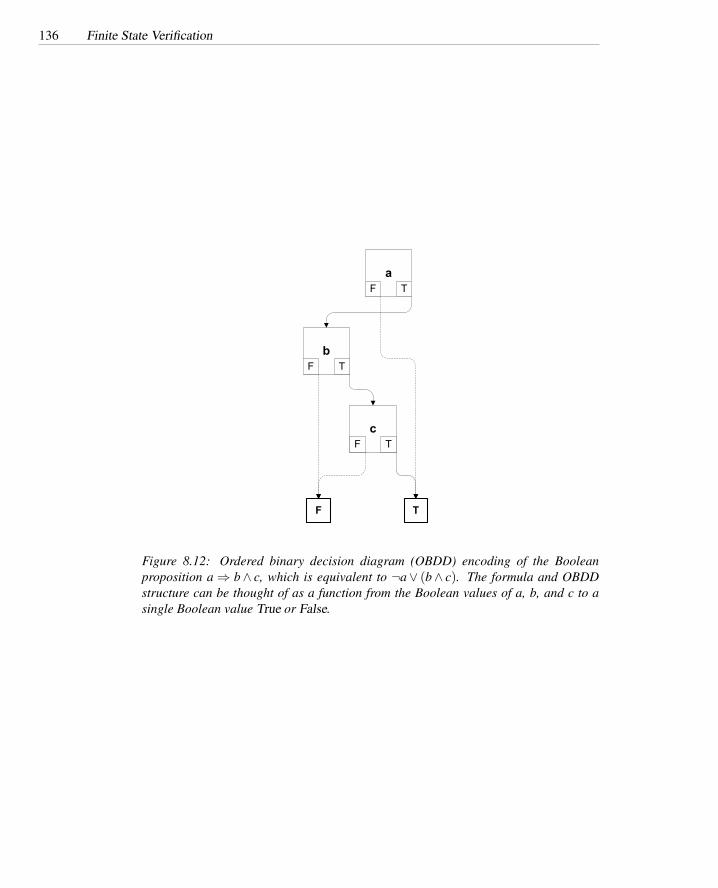
136 Finite State Verification
aF T
bF T
cF T
F T
Figure 8.12: Ordered binary decision diagram (OBDD) encoding of the Booleanproposition a ⇒ b∧ c, which is equivalent to ¬a∨ (b∧ c). The formula and OBDDstructure can be thought of as a function from the Boolean values of a, b, and c to asingle Boolean value True or False.

Intensional Models 137
x00 T
F T
s0 (00)
s1 (01)
s2 (10)
b (x0=1)
b (x0=1)
b (x0=1)
00 0000 0101 10
011
x1x2 x3x4x0
from state to statesym
x10 1
x20 1
x30 1
x40 1
x10 1
x20 1
x30 1
x40 1
x30 1
(A)
(B)
(C)
Figure 8.13: Ordered binary decision diagram (OBDD) representation of a transitionrelation, in three steps. In part (A), each state and symbol in the state machine isassigned a Boolean label. For example, state s0 is labeled 00. In part (B), transitionsare encoded as tuples 〈sym, from, to〉 indicating a transition from state from to state toon input symbol sym. In part (C), the transition tuples correspond to paths leading tothe True leaf of the OBDD, while all other paths lead to False. The OBDD representsa characteristic function that takes valuations of x0 . . .x4 and returns True only if itcorresponds to a state transition.

138 Finite State Verification
A good rule of thumb is that finite state verification tools that use intensional rep-resentations (typically called symbolic model checkers) are more effective, the moreregularity is captured in the model, while an explicit model checker (like Spin) is aptto be at least as effective where little regularity can be captured, or where the kindsof regularity that can be captured can also be exploited in explicit state space explo-ration (e.g., the partial order reductions used by Spin). Unfortunately, this advice israther vague, because we do not know a precise way to describe or measure the kindsof regularity that affect verification tool performance.
Whether a finite state verification tool performs explicit state enumeration or ma-nipulates an intensional representation can be partly hidden from the tool user, and it ispossible for a single tool “front end” for building or extracting models to be connectedto multiple “back end” verification engines.
8.7 Model Refinement
Because construction of finite state models requires a delicate balance between preci-sion and efficiency, often the first model we construct will be unsatisfactory — eitherthe verification tool will produce reports of potential failures that are obviously impos-sible, or it will exhaust resources before producing any result at all. Minor differencesin the model can have large effects on tractability of the verification procedure, so inpractice finite state verification is often an iterative process of constructing a model,attempting verification, and then either abstracting the model further (if the verificationexhausts computational resources or the user’s patience before obtaining a conclusiveresult) or making the model more precise to eliminate spurious results (i.e., a report ofa potential error that cannot actually occur).
An iterative process of model refinement can be at least partly automated. We beginwith a very coarse model that can be efficiently constructed and analyzed, and then weadd detail specifically aimed at ruling out spurious error reports. There are two mainapproaches: adding detail directly to the model, or adding premises to the property tobe checked.
Initially, we try to verify that a very coarse model M1 satisfies property P:
M1 |= P
However, M is only an approximation of the real system, and we find that the veri-fication finds a violation of P because of some execution sequences that are possible inM1 but not in the real system. In the first approach, we examine the counter-example(an execution trace of M1 that violates P but is impossible in the real system) and createa new model M2 that is more precise in a way that will eliminate that particular exe-cution trace (and many similar traces). We attempt verification again with the refinedmodel:
M2 |= P
If verification fails again, we repeat the process to obtain a new model M3, andso on, until verification succeeds with some “good enough” model Mk or we obtain acounter-example that corresponds to an execution of the actual program.

Model Refinement 139
One kind of model that can be iteratively refined in this way is Boolean pro-grams. The initial Boolean program model of an (ordinary) program omits all vari-ables; branches (if, while, etc.) refer to a dummy Boolean variable whose value is un-known. Boolean programs are refined by adding variables, with assignments and tests— but only Boolean variables. For instance, if a counter-example produced by trying toverify a property of a pump controller shows that the waterLevel variable cannot be ig-nored, a Boolean program might be refined by adding a Boolean variable correspondingto a predicate in which waterLevel is tested (say, waterLevel < highLimit), rather thanadding the variable waterLevel itself. For some kinds of interprocedural control flowanalysis, it is possible to completely automate the step of choosing additional Booleanvariables to refine Mi into Mi+1 and eliminate some spurious executions.
In the second approach, M remains fixed,4 but premises that constrain executionsto be checked are added to the property P. When bogus behaviors of M violate P, weadd a constraint C1 to rule them out and try the modified verification problem:
M |= C1 ⇒ P
If the modified verification problem fails because of additional bogus behaviors,we try again with new constraints C2:
M |= (C1∧C2)⇒ P
so on until verification either succeeds or produces a valid counter-example.The FLAVERS finite state verification tool is an example of the second approach,
adding constraints to refine a model of concurrent execution. A FLAVERS model ap-proximates concurrent execution with a pairwise “may immediately precede” (MIP)relation among operations in different threads. Because MIP relates only pairs of indi-vidual process states, rather than k-tuples for a model with k processes, its size is onlyquadratic in the size of the state machine model, rather than exponential in the numberof processes. Moreover, a reasonably good approximation of the MIP relation can beobtained in cubic time.5
If one thinks of each MIP edge in the program model as representing possible inter-ruption of one thread and continuation of another, it is apparent that paths combiningtransitions within individual processes and MIP transitions between processes can rep-resent all paths through the global state space. Many additional paths, which wouldnot appear in a more precise global model of possible executions, are also represented.The overapproximation leads to spurious error reports involving impossible executionpaths.
Additional spurious error reports result from eliding details of data variables. Inthe Boolean programs approach to model refinement, we would refine the model by
4In practice the model M may be augmented slightly to facilitate observing significant events in theconstraint, but the augmentation does not restrict or change the possible behaviors of the model M.
5Published algorithms for computing the “may immediately precede” relation, or the closely related “mayhappen in parallel” (MHP) relation, range from O(n3) to O(n6) where n is the sum of the sizes of the indi-vidual state machine models or control flow graphs. They differ depending on the thread interactions underconsideration (e.g., a MIP calculation for Ada tasks would use diffferent constraints than a MIP calculationfor Java threads) as well as algorithmic approach.

140 Finite State Verification
expanding the finite state representation of the process. With FLAVERS, in contrast, in-formation about the variable value is represented in a separate constraint state machine,which may be provided by the user or extracted automatically from the program to beverified. Only violations of property P that satisfy all the constraints Ci are reported.The same approach of adding constraints is used to eliminate spurious error reportsresulting from the MIP overestimation of possible concurrency.
8.8 Data Model Verification with Relational Algebra
Many information systems have relatively simple logic and algorithms, with much oftheir complexity in the structure of the data they maintain. A data model is a key designdescription for such systems. It is typically described, for example, in the class andobject diagrams of a Unified Modeling Language (UML) design document, possiblyaugmented by assertions in the Object Constraint Language (OCL). The finite stateverification techniques we have described are suited to reasoning about complex orsubtle program logic, but are quite limited in dealing with complex data. Fortunately,suitable finite state verification techniques can also be devised for reasoning about datamodels.
The data model consists of sets of data and relations among them. Often a datamodel describes many individual relations and constraints; the challenge is in know-ing whether all of the individual constraints are consistent, and whether together theyensure the desired properties of the system as a whole. Constructing and testing aportion or partial version of the system may provide some increased confidence in therealizability of the system, but even with incremental development it can happen that afundamental problem in the data model is discovered only after a great deal of devel-opment effort has been invested in the flawed model. Reasoning about the model itselfis a more timely and cost-effective way to find and correct these flaws.
Let us consider, for example, a simple Web site with a data model described as setsand relations as follows:
• A set of pages, divided among restricted, unrestricted, and maintenance pages.Unrestricted pages are freely accessible, while restricted pages are accessibleonly to registered users, and pages in maintenance are currently inaccessible toboth sets of users.
• A set of users, classified as administrator, registered, and unregistered users.
• A set of links relations among pages. Different relations describe different kindsof links. Private links lead to restricted pages, public links lead to unrestrictedpages, and maintenance links lead to pages undergoing maintenance.
• A set of access rights relations between users and pages, relating different classesof users to the pages they can access. Unregistered users can access only unre-stricted pages, registered users can access both restricted and unrestricted pages,and an administrator can access all pages, including pages under maintenance.

Data Model Verification with Relational Algebra 141
rA
B
A B
users
administrator registered
unregistered
page
unrestricted
restricted maintenancecan access
can access
can accessmaintenance
maintenance
private
private
public
public
LEGEND
Set B specializes
set A There is a relation r between sets A and B
can access
can access
can access
Figure 8.14: The data model of a simple Web site.
So far we have identified the sets involved in the relations, which we call theirsignature. To complete the description we need to indicate the rules that constrainrelations among specific elements. For example we may:
• Exclude self loops from “links” relations; that is, specify that a page should notbe directly linked to itself.
• Allow at most one type of link between two pages. Note that relations need notbe symmetric; that is, the relation between A and B is distinct from the relationbetween B and A, so there can be a link of type private from A to B and a link oftype public from B back to A.
• Require the Web site to be connected; that is, require that there be at least oneway of following links from the home page to each other page of the site.
A data model can be visualized as a diagram with nodes corresponding to sets andedges representing relations, as in Figure 8.14.
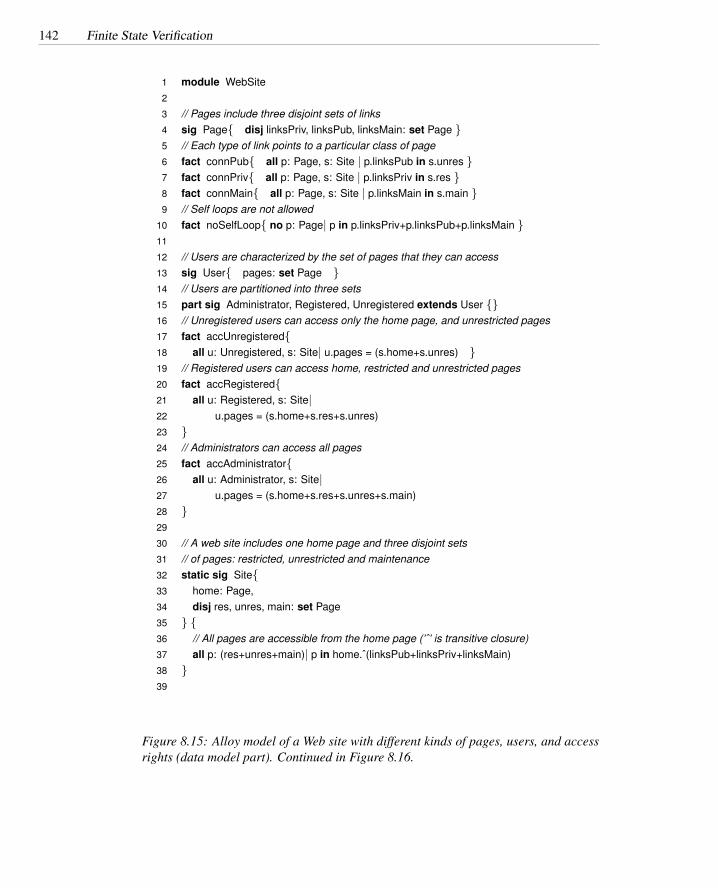
142 Finite State Verification
1 module WebSite2
3 // Pages include three disjoint sets of links4 sig Page{ disj linksPriv, linksPub, linksMain: set Page }5 // Each type of link points to a particular class of page6 fact connPub{ all p: Page, s: Site | p.linksPub in s.unres }7 fact connPriv{ all p: Page, s: Site | p.linksPriv in s.res }8 fact connMain{ all p: Page, s: Site | p.linksMain in s.main }9 // Self loops are not allowed
10 fact noSelfLoop{ no p: Page| p in p.linksPriv+p.linksPub+p.linksMain }11
12 // Users are characterized by the set of pages that they can access13 sig User{ pages: set Page }14 // Users are partitioned into three sets15 part sig Administrator, Registered, Unregistered extends User {}16 // Unregistered users can access only the home page, and unrestricted pages17 fact accUnregistered{18 all u: Unregistered, s: Site| u.pages = (s.home+s.unres) }19 // Registered users can access home, restricted and unrestricted pages20 fact accRegistered{21 all u: Registered, s: Site|22 u.pages = (s.home+s.res+s.unres)23 }24 // Administrators can access all pages25 fact accAdministrator{26 all u: Administrator, s: Site|27 u.pages = (s.home+s.res+s.unres+s.main)28 }29
30 // A web site includes one home page and three disjoint sets31 // of pages: restricted, unrestricted and maintenance32 static sig Site{33 home: Page,34 disj res, unres, main: set Page35 } {36 // All pages are accessible from the home page (’ˆ’ is transitive closure)37 all p: (res+unres+main)| p in home.ˆ(linksPub+linksPriv+linksMain)38 }39
Figure 8.15: Alloy model of a Web site with different kinds of pages, users, and accessrights (data model part). Continued in Figure 8.16.

Data Model Verification with Relational Algebra 143
1 module WebSite39 . . .40 // We consider one Web site that includes one home page41 // and some other pages42 fun initSite() {43 one s: Site| one s.home and44 some s.res and45 some s.unres and46 some s.main47 }48
49 // We consider one administrator and some registered and unregistered users50 fun initUsers() {one Administrator and51 some Registered and52 some Unregistered}53
54 fun init() {55 initSite() and initUsers()56 }57
58 // ANALYSIS59
60 // Verify if there exists a solution61 // with sets of cardinality at most 562 run init for 563
64 // check if unregistered users can visit all unrestrited pages,65 // i.e., all unrestricted pages are connected to the home page with66 // at least a path of public links.67 // Perform analysis with sets of at most 3 objects.68 // ’*’ indicates the transtivie closure including the source element.69
70 assert browsePub{71 all p: Page, s: Site| p in s.unres implies s.home in p.* linksPub72 }73 check browsePub for 3
Figure 8.16: Alloy model of a Web site with different kinds of pages, users, and accessrights, continued from Figure 8.15.
144 Finite State Verification
We can reason about sets and relations using mathematical laws. For example,set union and set intersection obey many of the same algebraic laws as addition andsubtraction of integers:
A∪B = B∪A commutative lawA∩B = B∩A " "(A∪B)∪C = A∪ (B∪C) associative law(A∩B)∩C = A∩ (B∩C) " "A∩ (B∪C) = (A∩B)∪ (A∩C) distributive lawetc.
These and many other laws together make up relational algebra, which is usedextensively in database processing and has many other uses.
It would be inconvenient to write down a data model directly as a collection ofmathematical formulas. Instead, we use some notation whose meaning is the same asthe mathematical formulas, but is easier to write, maintain, and comprehend. Alloy isone such modeling notation, with the additional advantage that it can be processed bya finite state verification tool.
The definition of the data model as sets and relations can be formalized and verifiedwith relational algebra by specifying signatures and constraints. Figure 8.15 presents aformalization of the data model of the Web site in Alloy. Keyword sig (signature) iden-tifies three sets: Pages, User, and Site. The definition of set Pages also defines threedisjoint relations among pages: linksPriv (private links), linksPub (public links), andlinksMain (maintenance links). The definition of User also defines a relation betweenusers and pages. User is partitioned into three disjoint sets (Administrator, Registered,and Unregistered). The definition of Site aggregates pages into the site and identifiesthe home page. Site is defined static since it is a fixed classification of objects.
The keyword facts introduces constraints.6 The constraints connPub, connPriv andconnMain restrict the target of the links relations, while noSelfLoop excludes links froma page to itself. The constraints accAdministrator, accRegistered, and accUnregisteredmap users to pages. The constraint that follows the definition of Site forces the Website to be connected by requiring each page to belong to the transitive closure of linksstarting from the Web page (operator ‘ˆ’).
A relational algebra specification may be over- or underconstrained. Overcon-strained specifications are not satisfiable by any implementation, while underconstrainedspecifications allow undesirable implementations; that is, implementations that violateimportant properties.
In general, specifications identify infinite sets of solutions, each characterized bya different set of objects and relations (e.g., the infinite set of Web sites with differentsets of pages, users and correct relations among them). Thus in general, properties of arelational specification are undecidable because proving them would require examiningan infinite set of possible solutions. While attempting to prove absence of a solutionmay be inconclusive, often a (counter) example that invalidates a property can be foundwithin a finite set of small models.
We can verify a specification over a finite set of solutions by limiting the cardinality
6The order in which relations and constraints are given is irrelevant. We list constraints after the relationsthey refer to.

Data Model Verification with Relational Algebra 145
User_2
Page_1
Page_0
Page_2
home unres
Site_0
unres
pages
pageslinkPriv
res
linksPub
linksPub
Figure 8.17: A Web site that violates the “browsability” property, because public pagePage 2 is not reachable from the home page using only unrestricted links. This diagramwas generated by the Alloy tool.
of the sets. In the example, we first verify that the model admits solutions for sets withat most five elements (run init for 5 issued after an initialization of the system.) Apositive outcome indicates that the specification is not overconstrained — there are nological contradictions. A negative outcome would not allow us to conclude that nosolution exists, but tells us that no “reasonably small” solution exists.
We then verify that the example is not underconstrained with respect to propertybrowsePub that states that unregistered users must be able to visit all unrestricted pagesby accessing the site from the home page. The property is asserted by requiring thatall unrestricted pages belong to the reflexive transitive closure of the linkPub relationfrom the home page (here we use operator ‘*’ instead of ’ˆ’ because the home pageis included in the closure). If we check whether the property holds for sets with atmost three elements (check browsePub for 3) we obtain a counter-example like the oneshown in Figure 8.17, which shows how the property can be violated.
The simple Web site in the example consists of two unrestricted pages (page 1,the home page, and page 2), one restricted page (page 0), and one unregistered user(user 2). User 2 cannot visit one of the unrestricted pages (page 2) because the onlypath from the home page to page 2 goes through the restricted page page 0. The prop-erty is violated because unrestricted browsing paths can be “interrupted” by restrictedpages or pages under maintenance, for example, when a previously unrestricted pageis reserved or disabled for maintenance by the administrator.
The problem appears only when there are public links from maintenance or re-

146 Finite State Verification
served pages, as we can check by excluding them:1 fact descendant{2 all p: Page, s: Site| p in s.main+s.res implies no p.linksPub3 }
This new specification would not find any counter-example in a space of cardinality 3.We cannot conclude that no larger counter-example exists, but we may be satisfied thatthere is no reason to expect this property to be violated only in larger models.
Summary
Finite state verification techniques fill an important niche in verifying critical proper-ties of programs. They are particularly crucial where nondeterminism makes programtesting ineffective, as in concurrent execution. In principle, finite state verification ofconcurrent execution and of data models can be seen as systematically exploring anenormous space of possible program states. From a user’s perspective, the challengeis to construct a suitable model of the software that can be analyzed with reasonableexpenditure of human and computational resources, captures enough significant detailfor verification to succeed, and can be shown to be consistent with the actual software.
Further Reading
There is a large literature on finite state verification techniques reaching back at least tothe 1960s, when Bartlett et al. [BSW69] employed what is recognizably a manual ver-sion of state space exploration to justify the corrrectness of a communication protocol.A number of early state space verification tools were developed initially for commu-nication protocol verification, including the Spin tool. Holzmann’s journal descriptionof Spin’s design and use [Hol97], though now somewhat out of date, remains an ade-quate introduction to the approach, and a full primer and reference manual [Hol03] isavailable in book form.
The ordered binary decision diagram representation of Boolean functions, used inthe first symbolic model checkers, was introduced by Randal Bryant [Bry86]. Therepresentation of transition relations as OBDDs in this chapter is meant to illustratebasic ideas but is simplified and far from complete; Bryant’s survey paper [Bry92] isa good source for understanding applications of OBDDs, and Huth and Ryan [HR00]provide a thorough and clear step-by-step description of how OBDDs are used in theSMV symbolic model checker.
Model refinement based on iterative refinements of an initial coarse model wasintroduced by Ball and Rajamani in the tools Slam [BR01a] and Bebop [BR01b], andby Henzinger and his colleagues in Blast [HJMS03]. The complementary refinementapproach of FLAVERS was introduced by Dwyer and colleagues [DCCN04].
Automated analysis of relational algebra for data modeling was introduced byDaniel Jackson and his students with the Alloy notation and associated tools [Jac02].

Data Model Verification with Relational Algebra 147
Exercises
8.1. We stated, on the one hand, that finite state verification falls between basic flowanalysis and formal verification in power and cost, but we also stated that fi-nite state verification techniques are often designed to provide results that aretantamount to formal proofs of program properties. Are these two statementscontradictory? If not, how can a technique that is less powerful than formalverification produce results that are tantamount to formal proofs?
8.2. Construct an ordered binary decision diagram (OBDD) for the proposition
x ⇒ y∨ z
8.3. (a) How does the size of the OBDD representation of
(x∨ y)∧¬(x∧ y∧ z)
differ depending on which variable (x, y, or z) is first in the variable ordering(i.e., appears in the root node of the OBDD representation)? Is the size ofthe OBDD equivalent for some different orderings of the variables? Whyor why not?
(b) Predict whether the order of variables would make a difference for
(x∨ y∨ z)∧¬(x∧ y∧ z)
8.4. A property like “if the button is pressed, then eventually the elevator will come”is classified as a liveness property. However, the stronger real-time version “if thebutton is pressed, then the elevator will arrive within 30 seconds” is technicallya safety property rather than a liveness property. Why?

148 Finite State Verification

Part III
Problems and Methods
149


Chapter 9
Test Case Selection andAdequacy
A key problem in software testing is selecting and evaluating test cases. This chapterintroduces basic approaches to test case selection and corresponding adequacy criteria.It serves as a general introduction to the problem and provides a conceptual frameworkfor functional and structural approaches described in subsequent chapters.
Required Background
• Chapter 2The fundamental problems and limitations of test case selection are a conse-quence of the undecidability of program properties. A grasp of the basic problemis useful in understanding Section 9.3.
9.1 Overview
Experience suggests that software that has passed a thorough set of systematic testsis likely to be more dependable than software that has been only superficially or hap-hazardly tested. Surely we should require that each software module or subsystemundergo thorough, systematic testing before being incorporated into the main product.But what do we mean by thorough testing? What is the criterion by which we canjudge the adequacy of a suite of tests that a software artifact has passed?
Ideally, we should like an “adequate” test suite to be one that ensures correctnessof the product. Unfortunately, that goal is not attainable. The difficulty of proving thatsome set of test cases is adequate in this sense is equivalent to the difficulty of provingthat the program is correct. In other words, we could have “adequate” testing in thissense only if we could establish correctness without any testing at all.
In practice we settle for criteria that identify inadequacies in test suites. For ex-ample, if the specification describes different treatment in two cases, but the test suitedoes not check that the two cases are in fact treated differently, then we may conclude
151

152 Test Case Selection and Adequacy
that the test suite is inadequate to guard against faults in the program logic. If no testin the test suite executes a particular program statement, we might similarly concludethat the test suite is inadequate to guard against faults in that statement. We may use awhole set of (in)adequacy criteria, each of which draws on some source of informationabout the program and imposes a set of obligations that an adequate set of test casesought to satisfy. If a test suite fails to satisfy some criterion, the obligation that has notbeen satisfied may provide some useful information about improving the test suite. Ifa set of test cases satisfies all the obligations by all the criteria, we still do not knowdefinitively that it is a well-designed and effective test suite, but we have at least someevidence of its thoroughness.
9.2 Test Specifications and Cases
A test case includes not only input data but also any relevant execution conditions andprocedures, and a way of determining whether the program has passed or failed thetest on a particular execution. The term input is used in a very broad sense, whichmay include all kinds of stimuli that contribute to determining program behavior. Forexample, an interrupt is as much an input as is a file. The pass/fail criterion might begiven in the form of expected output, but could also be some other way of determiningwhether a particular program execution is correct.
A test case specification is a requirement to be satisfied by one or more actual testcases. The distinction between a test case specification and a test case is similar to thedistinction between a program specification and a program. A test case specificationmight be met by several different test cases, and vice versa. Suppose, for example, weare testing a program that sorts a sequence of words. “The input is two or more words”would be a test case specification, while test cases with the input values “alpha beta”and “Milano Paris London” would be two among many test cases satisfying the testcase specification. A test case with input “Milano Paris London” would satisfy both thetest case specification “the input is two or more words” and the test case specification“the input contains a mix of lower- and upper-case alphabetic characters.”
Characteristics of the input are not the only thing that might be mentioned in atest case specification. A complete test case specification includes pass/fail criteriafor judging test execution and may include requirements, drawn from any of severalsources of information, such as system, program, and module interface specifications;source code or detailed design of the program itself; and records of faults encounteredin other software systems.
Test specifications drawn from system, program, and module interface specifica-tions often describe program inputs, but they can just as well specify any observable be-havior that could appear in specifications. For example, the specification of a databasesystem might require certain kinds of robust failure recovery in case of power loss, andtest specifications might therefore require removing system power at certain criticalpoints in processing. If a specification describes inputs and outputs, a test specificationcould prescribe aspects of the input, the output, or both. If the specification is mod-eled as an extended finite state machine, it might require executions corresponding toparticular transitions or paths in the state-machine model. The general term for such

Test Specifications and Cases 153
Testing TermsWhile the informal meanings of words like “test” may be adequate for everyday
conversation, in this context we must try to use terms in a more precise and consistentmanner. Unfortunately, the terms we will need are not always used consistently in theliterature, despite the existence of an IEEE standard that defines several of them. Theterms we will use are defined as follows.
Test case: A test case is a set of inputs, execution conditions, and a pass/fail criterion.(This usage follows the IEEE standard.)
Test case specification: A test case specification is a requirement to be satisfied byone or more actual test cases. (This usage follows the IEEE standard.)
Test obligation: A test obligation is a partial test case specification, requiring someproperty deemed important to thorough testing. We use the term obligation todistinguish the requirements imposed by a test adequacy criterion from morecomplete test case specifications.
Test suite: A test suite is a set of test cases. Typically, a method for functional testingis concerned with creating a test suite. A test suite for a program, system, orindividual unit may be made up of several test suites for individual modules,subsystems, or features. (This usage follows the IEEE standard.)
Test or test execution: We use the term test or test execution to refer to the activityof executing test cases and evaluating their results. When we refer to “a test,” wemean execution of a single test case, except where context makes it clear that thereference is to execution of a whole test suite. (The IEEE standard allows thisand other definitions.)
Adequacy criterion: A test adequacy criterion is a predicate that is true (satisfied)or false (not satisfied) of a 〈program, test suite〉 pair. Usually a test adequacycriterion is expressed in the form of a rule for deriving a set of test obligationsfrom another artifact, such as a program or specification. The adequacy criterionis then satisfied if every test obligation is satisfied by at least one test case in thesuite.
154 Test Case Selection and Adequacy
test specifications is functional testing, although the term black-box testing and morespecific terms like specification-based testing and model-based testing are also used.
Test specifications drawn from program source code require coverage of particularelements in the source code or some model derived from it. For example, we mightrequire a test case that traverses a loop one or more times. The general term for testingbased on program structure is structural testing, although the term white-box testing orglass-box testing is sometimes used.
Previously encountered faults can be an important source of information regard-ing useful test cases. For example, if previous products have encountered failures orsecurity breaches due to buffer overflows, we may formulate test requirements specif-ically to check handling of inputs that are too large to fit in provided buffers. Thesefault-based test specifications usually draw also from interface specifications, designmodels, or source code, but add test requirements that might not have been otherwiseconsidered. A common form of fault-based testing is fault-seeding, purposely insertingfaults in source code and then measuring the effectiveness of a test suite in finding theseeded faults, on the theory that a test suite that finds seeded faults is likely also to findother faults.
Test specifications need not fall cleanly into just one of the categories. For example,test specifications drawn from a model of a program might be considered specification-based if the model is produced during program design, or structural if it is derived fromthe program source code.
Consider the Java method of Figure 9.1. We might apply a general rule that requiresusing an empty sequence wherever a sequence appears as an input; we would thuscreate a test case specification (a test obligation) that requires the empty string as input.1
If we are selecting test cases structurally, we might create a test obligation that requiresthe first clause of the if statement on line 15 to evaluate to true and the second clause toevaluate to false, and another test obligation on which it is the second clause that mustevaluate to true and the first that must evaluate to false.
9.3 Adequacy Criteria
We have already noted that adequacy criteria are just imperfect but useful indicators ofinadequacies, so we may not always wish to use them directly to generate test specifi-cations from which actual test cases are drawn. We will use the term test obligation fortest specifications imposed by adequacy criteria, to distinguish them from test specifi-cations that are actually used to derive test cases. Thus, the usual situation will be thata set of test cases (a test suite) is created using a set of test specifications, but then theadequacy of that test suite is measured using a different set of test obligations.
We say a test suite satisfies an adequacy criterion if all the tests succeed and ifevery test obligation in the criterion is satisfied by at least one of the test cases inthe test suite. For example, the statement coverage adequacy criterion is satisfied by aparticular test suite for a particular program if each executable statement in the program(i.e., excluding comments and declarations) is executed by at least one test case in the
1Constructing and using catalogs of general rules like this is described in Chapter 10.

Adequacy Criteria 155
1 /**2 * Remove/collapse multiple spaces.3 *4 * @param String string to remove multiple spaces from.5 * @return String6 */7 public static String collapseSpaces(String argStr)8 {9 char last = argStr.charAt(0);
10 StringBuffer argBuf = new StringBuffer();11
12 for (int cIdx = 0 ; cIdx < argStr.length(); cIdx++)13 {14 char ch = argStr.charAt(cIdx);15 if (ch != ’ ’ || last != ’ ’)16 {17 argBuf.append(ch);18 last = ch;19 }20 }21
22 return argBuf.toString();23 }
Figure 9.1: A Java method for collapsing sequences of blanks, excerpted from theStringUtils class of Velocity version 1.3.1, an Apache Jakarta project. c© ApacheGroup, used by permission.

156 Test Case Selection and Adequacy
test suite. A fault-based adequacy criterion that seeds a certain set of faults would besatisfied if, for each of the seeded faults, there is a test case that passes for the originalprogram but fails for the program with (only) that seeded fault.
It is quite possible that no test suite will satisfy a particular test adequacy criterionfor a particular program. For example, if the program contains statements that cannever be executed (perhaps because it is part of a sanity check that can be executedonly if some other part of the program is faulty), then no test suite can satisfy thestatement coverage criterion. Analogous situations arise regardless of the sources ofinformation used in devising test adequacy criteria. For example, a specification-basedcriterion may require combinations of conditions drawn from different parts of thespecification, but not all combinations may be possible.
One approach to overcoming the problem of unsatisfiable test obligations is to sim-ply exclude any unsatisfiable obligation from a criterion. For example, the statementcoverage criterion can be modified to require execution only of statements that canbe executed. The question of whether a particular statement or program path is exe-cutable, or whether a particular combination of clauses in a specification is satisfiable,or whether a program with a seeded error actually behaves differently from the originalprogram, are all provably undecidable in the general case. Thus, while tools may besome help in distinguishing feasible from infeasible test obligations, in at least somecases the distinction will be left to fallible human judgment.
If the number of infeasible test obligations is modest, it can be practical to identifyeach of them, and to ameliorate human fallibility through peer review. If the numberof infeasible test obligations is large, it becomes impractical to carefully reason abouteach to avoid excusing an obligation that is feasible but difficult to satisfy. A commonpractice is to measure the extent to which a test suite approaches an adequacy criterion.For example, if an adequacy criterion based on control flow paths in a program unitinduced 100 distinct test obligations, and a test suite satisfied 85 of those obligations,then we would say that we had reached 85% coverage of the test obligations.
Quantitative measures of test coverage are widely used in industry. They are simpleand cheap to calculate, provide some indication of progress toward thorough testing,and project an aura of objectivity. In managing software development, anything thatproduces a number can be seductive. One must never forget that coverage is a roughproxy measure for the thoroughness and effectiveness of test suites. The danger, aswith any proxy measure of some underlying goal, is the temptation to improve theproxy measure in a way that does not actually contribute to the goal. If, for example,80% coverage of some adequacy criterion is required to declare a work assignmentcomplete, developers under time pressure will almost certainly yield to the temptationto design tests specifically to that criterion, choosing the simplest test cases that achievethe required coverage level. One cannot entirely avoid such distortions, but to theextent possible one should guard against them by ensuring that the ultimate measureof performance is preventing faults from surviving to later stages of development ordeployment.

Comparing Criteria 157
9.4 Comparing Criteria
It would be useful to know whether one test adequacy criterion was more effectivethan another in helping find program faults, and whether its extra effectiveness wasworthwhile with respect to the extra effort expended to satisfy it. One can imaginetwo kinds of answers to such a question, empirical and analytical. An empirical an-swer would be based on extensive studies of the effectiveness of different approachesto testing in industrial practice, including controlled studies to determine whether therelative effectiveness of different testing methods depends on the kind of software be-ing tested, the kind of organization in which the software is developed and tested, anda myriad of other potential confounding factors. The empirical evidence available fallsshort of providing such clear-cut answers. An analytical answer to questions of relativeeffectiveness would describe conditions under which one adequacy criterion is guar-anteed to be more effective than another, or describe in statistical terms their relativeeffectiveness.
Analytic comparisons of the strength of test coverage depends on a precise defini-tion of what it means for one criterion to be “stronger” or “more effective” than another.Let us first consider single test suites. In the absence of specific information, we cannotexclude the possibility that any test case can reveal a failure. A test suite TA that doesnot include all the test cases of another test suite TB may fail revealing the potentialfailure exposed by the test cases that are in TB but not in TA. Thus, if we consider onlythe guarantees that a test suite provides, the only way for one test suite TA to be strongerthan another suite TB is to include all test cases of TB plus additional ones.
Many different test suites might satisfy the same coverage criterion. To comparecriteria, then, we consider all the possible ways of satisfying the criteria. If every testsuite that satisfies some criterion A is a superset of some test suite that satisfies criterionB, or equivalently, every suite that satisfies A also satisfies B, then we can say that A“subsumes” B.
∆ subsumes
Test coverage criterion A subsumes test coverage criterion B iff, for every programP, every test set satisfying A with respect to P also satisfies B with respect to P.
In this case, if we satisfy criterion C1, there is no point in measuring adequacy withrespect to C2. For example, a structural criterion that requires exploring all outcomesof conditional branches subsumes statement coverage. Likewise, a specification-basedcriterion that requires use of a set of possible values for attribute A and, independently,for attribute B, will be subsumed by a criterion that requires all combinations of thosevalues.
Consider again the example of Figure 9.1. Suppose we apply an adequacy criterionthat imposes an obligation to execute each statement in the method. This criterion canbe met by a test suite containing a single test case, with the input value (value of argStr)being “doesn’tEvenHaveSpaces.” Requiring both the true and false branches of eachtest to be taken subsumes the previous criterion and forces us to at least provide aninput with a space that is not copied to the output, but it can still be satisfied by a suitewith just one test case. We might add a requirement that the loop be iterated zero times,once, and several times, thus requiring a test suite with at least three test cases. Theobligation to execute the loop body zero times would force us to add a test case with the

158 Test Case Selection and Adequacy
empty string as input, and like the specification-based obligation to consider an emptysequence, this would reveal a fault in the code.
Should we consider a more demanding adequacy criterion, as indicated by the sub-sumes relation among criteria, to be a better criterion? The answer would be “yes” ifwe were comparing the guarantees provided by test adequacy criteria: If criterion Asubsumes criterion B, and if any test suite satisfying B in some program is guaranteedto find a particular fault, then any test suite satisfying A is guaranteed to find the samefault in the program. This is not as good as it sounds, though. Twice nothing is nothing.Adequacy criteria do not provide useful guarantees for fault detection, so comparingguarantees is not a useful way to compare criteria.
A better statistical measure of test effectiveness is whether the probability of find-ing at least one program fault is greater when using one test coverage criterion thananother. Of course, such statistical measures can be misleading if some test coveragecriteria require much larger numbers of test cases than others. It is hardly surprisingif a criterion that requires at least 300 test cases for program P is more effective, onaverage, than a criterion that requires at least 50 test cases for the same program. Itwould be better to know, if we have 50 test cases that satisfy criterion B, is there anyvalue in finding 250 test cases to finish satisfying the “stronger” criterion A, or wouldit be just as profitable to choose the additional 250 test cases at random?
Although theory does not provide much guidance, empirical studies of particulartest adequacy criteria do suggest that there is value in pursuing stronger criteria, par-ticularly when the level of coverage attained is very high. Whether the extra value ofpursuing a stronger adequacy criterion is commensurate with the cost almost certainlydepends on a plethora of particulars, and can only be determined by monitoring resultsin individual organizations.
Open Research Issues
A good deal of theoretical research has been done on what one can conclude abouttest effectiveness from test adequacy criteria. Most of the results are negative. Ingeneral, one cannot be certain that a test suite that meets any practical test adequacycriterion ensures correctness, or even that it is more effective at finding faults thananother test suite that does not meet the criterion. While theoretical characterization oftest adequacy criteria and their properties was once an active research area, interest haswaned, and it is likely that future theoretical progress must begin with a quite differentconception of the fundamental goals of a theory of test adequacy.
The trend in research is toward empirical, rather than theoretical, comparison ofthe effectiveness of particular test selection techniques and test adequacy criteria. Em-pirical approaches to measuring and comparing effectiveness are still at an early stage.A major open problem is to determine when, and to what extent, the results of an em-pirical assessment can be expected to generalize beyond the particular programs andtest suites used in the investigation. While empirical studies have to a large extent dis-placed theoretical investigation of test effectiveness, in the longer term useful empiricalinvestigation will require its own theoretical framework.

Comparing Criteria 159
Further Reading
Goodenough and Gerhart made the original attempt to formulate a theory of “ade-quate” testing [GG75]; Weyuker and Ostrand extended this theory to consider when aset of test obligations is adequate to ensure that a program fault is revealed [WO80].Gourlay’s exposition of a mathematical framework for adequacy criteria is among themost lucid developments of purely analytic characterizations [Gou83]. Hamlet andTaylor show that, if one takes statistical confidence in (absolute) program correctnessas the goal, none of the standard coverage testing techniques improve on random testing[HT90], from which an appropriate conclusion is that confidence in absolute correct-ness is not a reasonable goal of systematic testing. Frankl and Iakounenko’s study oftest effectiveness [FI98] is a good example of the development of empirical methodsfor assessing the practical effectiveness of test adequacy criteria.
Related Topics
Test adequacy criteria and test selection techniques can be categorized by the sourcesof information they draw from. Functional testing draws from program and systemspecifications, and is described in Chapters 10, 11, and 14. Structural testing drawsfrom the structure of the program or system, and is described in Chapters 12 and 13.The techniques for testing object-oriented software described in Chapter 15 draw onboth functional and structural approaches. Selection and adequacy criteria based onconsideration of hypothetical program faults are described in Chapter 16.
Exercises
9.1. Deterministic finite state machines (FSMs), with states representing classes ofprogram states and transitions representing external inputs and observable pro-gram actions or outputs, are sometimes used in modeling system requirements.We can design test cases consisting of sequences of program inputs that triggerFSM transitions and the predicted program actions expected in response. We canalso define test coverage criteria relative to such a model. Which of the followingcoverage criteria subsume which others?
State coverage: For each state in the FSM model, there is a test case that visitsthat state.
Transition coverage: For each transition in the FSM model, there is a test casethat traverses that transition.
Path coverage: For all finite-length subpaths from a distinguished start state inthe FSM model, there is at least one test case that includes a correspondingsubpath.
State-pair coverage: For each state r in the FSM model, for each state s reach-able from r along some sequence of transitions, there is at least one testcase that passes through state r and then reaches state s.
160 Test Case Selection and Adequacy
9.2. Adequacy criteria may be derived from specifications (functional criteria) orcode (structural criteria). The presence of infeasible elements in a program maymake it impossible to obtain 100% coverage. Since we cannot possibly cover in-feasible elements, we might define a coverage criterion to require 100% coverageof feasible elements (e.g., execution of all program statements that can actuallybe reached in program execution). We have noted that feasibility of programelements is undecidable in general. Suppose we instead are using a functionaltest adequacy criterion, based on logical conditions describing inputs and out-puts. It is still possible to have infeasible elements (logical condition A might beinconsitent with logical condition B, making the conjunction A∧B infeasible).Would you expect distinguishing feasible from infeasible elements to be easieror harder for functional criteria, compared to structural criteria? Why?
9.3. Suppose test suite A satisfies adequacy criterion C1. Test suite B satisfies ade-quacy criterion C2, and C2 subsumes C1. Can we be certain that faults revealedby A will also be revealed by B?

Chapter 10
Functional Testing
A functional specification is a description of intended program1 behavior, distinct fromthe program itself. Whatever form the functional specification takes — whether formalor informal — it is the most important source of information for designing tests.Deriving test cases from program specifications is called functional testing.
Functional testing, or more precisely, functional test case design, attempts to an-swer the question “What test cases shall I use to exercise my program?” consideringonly the specification of a program and not its design or implementation structure. Be-ing based on program specifications and not on the internals of the code, functionaltesting is also called specification-based or black-box testing.
Functional testing is typically the base-line technique for designing test cases, fora number of reasons. Functional test case design can (and should) begin as part ofthe requirements specification process, and continue through each level of design andinterface specification; it is the only test design technique with such wide and early ap-plicability. Moreover, functional testing is effective in finding some classes of fault thattypically elude so-called white-box or glass-box techniques of structural or fault-basedtesting. Functional testing techniques can be applied to any description of program be-havior, from an informal partial description to a formal specification, and at any levelof granularity from module to system testing. Finally, functional test cases are typicallyless expensive to design and execute than white-box tests.
10.1 Overview
In testing and analysis aimed at verification2 — that is, at finding any discrepanciesbetween what a program does and what it is intended to do — one must obviouslyrefer to requirements as expressed by users and specified by software engineers. A
1We use the term program generically for the artifact under test, whether that artifact is a completeapplication or an individual unit together with a test harness. This is consistent with usage in the testingresearch literature.
2Here we focus on software verification as opposed to validation (see Chapter 2). The problems ofvalidating the software and its specifications, that is, checking the program behavior and its specificationswith respect to the users’ expectations, is treated in Chapter 22.
161
162 Functional Testing
functional specification, that is, a description of the expected behavior of the program,is the primary source of information for test case specification.
Functional testing, also known as black-box or specification-based testing, denotes∆ black-box testing
techniques that derive test cases from functional specifications. Usually functionaltesting techniques produce test case specifications that identify classes of test casesand are instantiated to produce individual test cases.
The core of functional test case design is partitioning3 the possible behaviors ofthe program into a finite number of homogeneous classes, where each such class canreasonably be expected to be consistently correct or incorrect. In practice, the test casedesigner often must also complete the job of formalizing the specification far enough toserve as the basis for identifying classes of behaviors. An important side benefit of testdesign is highlighting the weaknesses and incompleteness of program specifications.
Deriving functional test cases is an analytical process that decomposes specifica-tions into test cases. The myriad aspects that must be taken into account during func-tional test case specification makes the process error prone. Even expert test designerscan miss important test cases. A methodology for functional test design helps by de-composing the functional test design process into elementary steps. In this way, itis possible to control the complexity of the process and to separate human intensiveactivities from activities that can be automated.
Sometimes, functional testing can be fully automated. This is possible, for exam-ple, when specifications are given in terms of some formal model, such as a grammaror an extended state machine specification. In these (exceptional) cases, the creativework is performed during specification and design of the software. The test designer’sjob is then limited to the choice of the test selection criteria, which defines the strategyfor generating test case specifications. In most cases, however, functional test designis a human intensive activity. For example, when test designers must work from infor-mal specifications written in natural language, much of the work is in structuring thespecification adequately for identifying test cases.
10.2 Random versus Partition Testing Strategies
With few exceptions, the number of potential test cases for a given program is unimag-inably huge — so large that for all practical purposes it can be considered infinite. Forexample, even a simple function whose input arguments are two 32-bit integers has264 ≈ 1054 legal inputs. In contrast to input spaces, budgets and schedules are finite,so any practical method for testing must select an infinitesimally small portion of thecomplete input space.
Some test cases are better than others, in the sense that some reveal faults and othersdo not.4 Of course, we cannot know in advance which test cases reveal faults. At aminimum, though, we can observe that running the same test case again is less likely
3We are using the term partition in a common but rather sloppy sense. A true partition would formdisjoint classes, the union of which is the entire space. Partition testing separates the behaviors or inputspace into classes whose union is the entire space, but the classes may not be disjoint.
4Note that the relative value of different test cases would be quite different if our goal were to measuredependability, rather than finding faults so that they can be repaired.

Random versus Partition Testing Strategies 163
Functional vs. Structural TestingTest cases and test suites can be derived from several sources of information, in-
cluding specifications (functional and model-based testing), detailed design and sourcecode (structural testing), and hypothesized defects (fault-based testing). Functional testcase design is an indispensable base of a good test suite, complemented but never re-placed by structural and fault-based testing, because there are classes of faults that onlyfunctional testing effectively detects. Omission of a feature, for example, is unlikely tobe revealed by techniques that refer only to the code structure.
Consider a program that is supposed to accept files in either plain ASCII text, orHTML, or PDF formats and generate standard Postscript. Suppose the programmeroverlooks the PDF functionality, so that the program accepts only plain text and HTMLfiles. Intuitively, a functional testing criterion would require at least one test case foreach item in the specification, regardless of the implementation; that is, it would requirethe program to be exercised with at least one ASCII, one HTML, and one PDF file, thuseasily revealing the failure due to the missing code. In contrast, criteria based solely onthe code would not require the program to be exercised with a PDF file, since each partof the code can be exercised without attempting to use that feature. Similarly, fault-based techniques, based on potential faults in design or coding, would not have anyreason to indicate a PDF file as a potential input even if “missing case” were includedin the catalog of potential faults.
Functional specifications often address semantically rich domains, and we can usedomain information in addition to the cases explicitly enumerated in the program spec-ification. For example, while a program may manipulate a string of up to nine alphanu-meric characters, the program specification may reveal that these characters representa postal code, which immediately suggests test cases based on postal codes of vari-ous localities. Suppose the program logic distinguishes only two cases, depending onwhether they are found in a table of U.S. zip codes. A structural testing criterion wouldrequire testing of valid and invalid U.S. zip codes, but only consideration of the specifi-cation and richer knowledge of the domain would suggest test cases that reveal missinglogic for distinguishing between U.S.-bound mail with invalid U.S. zip codes and mailbound for other countries.
Functional testing can be applied at any level of granularity where some form ofspecification is available, from overall system testing to individual units, although thelevel of granularity and the type of software influence the choice of the specificationstyles and notations, and consequently the functional testing techniques that can beused.
In contrast, structural and fault-based testing techniques are invariably tied to pro-gram structures at some particular level of granularity and do not scale much beyondthat level. The most common structural testing techniques are tied to fine-grain pro-gram structures (statements, classes, etc.) and are applicable only at the level of mod-ules or small collections of modules (small subsystems, components, or libraries).

164 Functional Testing
to reveal a fault than running a different test case, and we may reasonably hypothesizethat a test case that is very different from the test cases that precede it is more valuablethan a test case that is very similar (in some sense yet to be defined) to others.
As an extreme example, suppose we are allowed to select only three test cases fora program that breaks a text buffer into lines of 60 characters each. Suppose the firsttest case is a buffer containing 40 characters, and the second is a buffer containing 30characters. As a final test case, we can choose a buffer containing 16 characters ora buffer containing 100 characters. Although we cannot prove that the 100-characterbuffer is the better test case (and it might not be; the fact that 16 is a power of 2 mighthave some unforeseen significance), we are naturally suspicious of a set of tests that isstrongly biased toward lengths less than 60.
Accidental bias may be avoided by choosing test cases from a random distribution.Random sampling is often an inexpensive way to produce a large number of test cases.If we assume absolutely no knowledge on which to place a higher value on one test casethan another, then random sampling maximizes value by maximizing the number of testcases that can be created (without bias) for a given budget. Even if we do possess someknowledge suggesting that some cases are more valuable than others, the efficiency ofrandom sampling may in some cases outweigh its inability to use any knowledge wemay have.
Consider again the line-break program, and suppose that our budget is one day oftesting effort rather than some arbitrary number of test cases. If the cost of randomselection and actual execution of test cases is small enough, then we may prefer to runa large number of random test cases rather than expending more effort on each of asmaller number of test cases. We may in a few hours construct programs that generatebuffers with various contents and lengths up to a few thousand characters, as well asan automated procedure for checking the program output. Letting it run unattendedovernight, we may execute a few million test cases. If the program does not correctlyhandle a buffer containing a sequence of more than 60 nonblank characters (a single“word” that does not fit on a line), we are likely to encounter this case by sheer luck ifwe execute enough random tests, even without having explicitly considered this case.
Even a few million test cases is an infinitesimal fraction of the complete input spaceof most programs. Large numbers of random tests are unlikely to find failures at singlepoints (singularities) in the input space. Consider, for example, a simple procedure forreturning the two roots of a quadratic equation ax2 +bx+c = 0 and suppose we choosetest inputs (values of the coefficients a, b, and c) from a uniform distribution rangingfrom −10.0 to 10.0. While uniform random sampling would certainly cover cases inwhich b2 − 4ac > 0 (where the equation has no real roots), it would be very unlikelyto test the case in which a = 0 and b = 0, in which case a naive implementation of thequadratic formula
x =−b±
√b2−4ac
2a
will divide by zero (see Figure 10.1).Of course, it is unlikely that anyone would test only with random values. Regard-
less of the overall testing strategy, most test designers will also try some “special”values. The test designer’s intuition comports with the observation that random sam-

Random versus Partition Testing Strategies 165
1 /** Find the two roots of axˆ2 + bx + c,2 * that is, the values of x for which the result is 0.3 */4 class Roots {5 double root one, root two;6 int num roots;7 public roots(double a, double b, double c) {8 double q;9 double r;
10 // Apply the textbook quadratic formula:11 // Roots = -b +- sqrt(bˆ2 - 4ac) / 2a12 q = b*b - 4*a*c;13 if (q > 0 && a != 0) {14 // If bˆ2 > 4ac, there are two distinct roots15 num roots = 2;16 r = (double) Math.sqrt(q) ;17 root one = ((0-b) + r)/(2*a);18 root two = ((0-b) - r)/(2*a);19 } else if (q==0) { // (BUG HERE)20 // The equation has exactly one root21 num roots = 1;22 root one = (0-b)/(2*a);23 root two = root one;24 } else {25 // The equation has no roots if bˆ2 < 4ac26 num roots = 0;27 root one = -1;28 root two = -1;29 }30 }31 public int num roots() { return num roots; }32 public double first root() { return root one; }33 public double second root() { return root two; }34 }
Figure 10.1: The Java class roots, which finds roots of a quadratic equation. The caseanalysis in the implementation is incomplete: It does not properly handle the casein which b2 − 4ac = 0 and a = 0. We cannot anticipate all such faults, but experi-ence teaches that boundary values identifiable in a specification are disproportionatelyvaluable. Uniform random generation of even large numbers of test cases is ineffectiveat finding the fault in this program, but selection of a few “special values” based onthe specification quickly uncovers it.

166 Functional Testing
pling is an ineffective way to find singularities in a large input space. The observationabout singularities can be generalized to any characteristic of input data that defines aninfinitesimally small portion of the complete input data space. If again we have justthree real-valued inputs a, b, and c, there is an infinite number of choices for whichb = c, but random sampling is unlikely to generate any of them because they are aninfinitesimal part of the complete input data space.
The observation about special values and random samples is by no means limitedto numbers. Consider again, for example, breaking a text buffer into lines. Sinceline breaks are permitted at blanks, we would consider blanks a “special” value forthis problem. While random sampling from the character set is likely to produce abuffer containing a sequence of at least 60 nonblank characters, it is much less likelyto produce a sequence of 60 blanks.
The reader may justifiably object that a reasonable test designer would not createtext buffer test cases by sampling uniformly from the set of all characters. The designerwould instead classify characters depending on their treatment, lumping alphabeticcharacters into one class and white space characters into another. In other words, a testdesigner will partition the input space into classes and will then generate test data ina manner that is likely to choose data from each partition. Test designers seldom usepure random sampling; usually they exploit some knowledge of application semanticsto choose samples that are more likely to include “special” or trouble-prone regions ofthe input space.
Partition testing separates the input space into classes whose union is the entirespace, but the classes may not be disjoint (and thus the term partition is not mathemati-cally accurate, although it has become established in testing terminology). Figure 10.2illustrates a desirable case: All inputs that lead to a failure belong to at least one classthat contains only inputs that lead to failures. In this case, sampling each class in thequasi-partition selects at least one input that leads to a failure, revealing the fault. Wecould easily turn the quasi-partition of Figure 10.2 into a true partition, by consideringintersections among the classes, but sampling in a true partition would not improve theefficiency or effectiveness of testing.
A testing method that divides the infinite set of possible test cases into a finite setof classes, with the purpose of drawing one or more test cases from each class, is calleda partition testing method. When partitions are chosen according to information in∆ partition testing
the specification, rather than the design or implementation, it is called specification-based partition testing, or more briefly, functional testing. Note that not all testing ofproduct functionality is “functional testing.” Rather, the term is used specifically to∆
specification-basedtesting
refer to systematic testing based on a functional specification. It excludes ad hoc andrandom testing, as well as testing based on the structure of a design or implementation.
∆ functional testing Partition testing typically increases the cost of each test case, since in additionto generation of a set of classes, creation of test cases from each class may be moreexpensive than generating random test data. In consequence, partition testing usuallyproduces fewer test cases than random testing for the same expenditure of time andmoney. Partitioning can therefore be advantageous only if the average value (faultdetection effectiveness) is greater.
If we were able to group together test cases with such perfect knowledge that theoutcome of test cases in each class were uniform (either all successes or all failures),

A Systematic Approach 167
Figure 10.2: A quasi-partition of a program’s input space. Black circles representinputs that lead to failures. All elements of the input domain belong to at least oneclass, but classes are not disjoint.
then partition testing would be at its theoretical best. In general we cannot do that,nor can we even quantify the uniformity of classes of test cases. Partitioning by anymeans, including specification-based partition testing, is always based on experienceand judgment that leads one to believe that certain classes of test case are “more alike”than others, in the sense that failure-prone test cases are likely to be concentrated insome classes. When we appealed earlier to the test designer’s intuition that one shouldtry boundary cases and special values, we were actually appealing to a combinationof experience (many failures occur at boundary and special cases) and knowledge thatidentifiable cases in the specification often correspond to classes of input that requiredifferent treatment by an implementation.
Given a fixed budget, the optimum may not lie in only partition testing or onlyrandom testing, but in some mix that makes use of available knowledge. For example,consider again the simple numeric problem with three inputs, a, b, and c. We mightconsider a few special cases of each input, individually and in combination, and wemight consider also a few potentially significant relationships (e.g., a = b). If no faultsare revealed by these few test cases, there is little point in producing further arbitrarypartitions — one might then turn to random generation of a large number of test cases.
10.3 A Systematic Approach
Deriving test cases from functional specifications is a complex analytical process thatpartitions the input space described by the program specification. Brute force genera-tion of test cases, that is, direct generation of test cases from program specifications,

168 Functional Testing
seldom produces acceptable results: Test cases are generated without particular cri-teria, and determining the adequacy of the generated test cases is almost impossible.Brute force generation of test cases relies on test designers’ expertise and is a processthat is difficult to monitor and repeat. A systematic approach simplifies the overall pro-cess by dividing it into elementary steps, thus decoupling different activities, dividingbrain-intensive from automatable steps, suggesting criteria to identify adequate sets oftest cases, and providing an effective means of monitoring the testing activity.
Although suitable functional testing techniques can be found for any granularitylevel, a particular functional testing technique may be effective only for some kindsof software or may require a given specification style. For example, a combinatorialapproach may work well for functional units characterized by a large number of rela-tively independent inputs, but may be less effective for functional units characterizedby complex interrelations among inputs. Functional testing techniques designed for agiven specification notation, for example, finite state machines or grammars, are noteasily applicable to other specification styles. Nonetheless, we can identify a generalpattern of activities that captures the essential steps in a variety of different functionaltest design techniques. By describing particular functional testing techniques as instan-tiations of this general pattern, relations among the techniques may become clearer, andthe test designer may gain some insight into adapting and extending these techniquesto the characteristics of other applications and situations.
Figure 10.3 identifies the general steps of systematic approaches. The steps maybe difficult or trivial depending on the application domain and the available programspecifications. Some steps may be omitted depending on the application domain, theavailable specifications and the test designers’ expertise. Instances of the process canbe obtained by suitably instantiating different steps. Although most techniques arepresented and applied as stand-alone methods, it is also possible to mix and matchsteps from different techniques, or to apply different methods for different parts of thesystem to be tested.
Identify Independently Testable Features Functional specifications can be largeand complex. Usually, complex specifications describe systems that can be decom-posed into distinct features. For example, the specification of a Web site may includefeatures for searching the site database, registering users’ profiles, getting and storinginformation provided by the users in different forms, and so on. The specification ofeach of these features may comprise several functionalities. For example, the searchfeature may include functionalities for editing a search pattern, searching the databasewith a given pattern, and so on. Although it is possible to design test cases that exerciseseveral functionalities at once, designing different test cases for different functionalitiescan simplify the test generation problem, allowing each functionality to be examinedseparately. Moreover, it eases locating faults that cause the revealed failures. It isthus recommended to devise separate test cases for each functionality of the system,whenever possible.
The preliminary step of functional testing consists in partitioning the specificationsinto features that can be tested separately. This can be an easy step for well-designed,modular specifications, but informal specifications of large systems may be difficult to

A Systematic Approach 169
Functional Specifications
Independently Testable Feature
ModelRepresentative Values
Test Case Specifications
Test Cases
Identify
Representative
Values
Iden
tify
Inde
pend
ently
Te
stab
le
Feat
ures
Derivea Model
Generate Test-Case
Specifications Generate Test-Case
Specifications
Gen
erat
e Te
st C
ases
Scaffolding
Inst
antia
teTe
sts
BruteForce
Testing
Finite State MachineGrammarAlgebraic SpecificationLogic SpecificationControl/Data Flow Graph
Semantic ConstraintsCombinatorial SelectionExhaustive EnumerationRandom Selection
Test Selection Criteria
Manual MappingSymbolic ExecutionA-posteriori Satisfaction
Figure 10.3: The main steps of a systematic approach to functional program testing.

170 Functional Testing
Units and FeaturesPrograms and software systems can be decomposed in different ways. For test-
ing, we may consider externally observable behavior (features), or the structure of thesoftware system (units, subsystems, and components).
Independently testable feature: An independently testable feature (ITF) is a func-tionality that can be tested independently of other functionalities of the softwareunder test. It need not correspond to a unit or subsystem of the software. Forexample, a file sorting utility may be capable of merging two sorted files, and itmay be possible to test the sorting and merging functionalities separately, eventhough both features are implemented by much of the same source code. (Thenearest IEEE standard term is test item.)
As functional testing can be applied at many different granularity levels, fromunit testing through integration and system testing, so ITFs may range from thefunctionality of an individual Java class or C function up to features of an inte-grated system composed of many complete programs. The granularity of an ITFdepends on the exposed interface at whichever granularity is being tested. Forexample, individual methods of a class are part of the interface of the class, and aset of related methods (or even a single method) might be an ITF for unit testing,but for system testing the ITFs would be features visible through a user interfaceor application programming interface.
Unit: We reserve the term unit, not for any fixed syntactic construct in a particular pro-gramming language, but for the smallest unit of work assignment in a softwareproject. Defining “unit” in this manner, rather than (for example) equating unitswith individual Java classes or packages, or C files or functions, reflects a phi-losophy about test and analysis. A work unit is the smallest increment by whicha software system grows or changes, the smallest unit that appears in a projectschedule and budget, and the smallest unit that may reasonably be associatedwith a suite of test cases.
It follows from our definition of “unit” that, when we speak of unit testing, wemean the testing associated with an individual work unit.
We reserve the term function for the mathematical concept, that is, a set of orderedpairs having distinct first elements. When we refer to “functions” as syntactic elementsin some programming language, we will qualify it to distinguish that usage from themathematical concept. A “function” is a set of ordered pairs but a “C function” is asyntactic element in the C programming language.
A Systematic Approach 171
decompose into independently testable features. Some degree of formality, at least tothe point of careful definition and use of terms, is usually required.
Identification of functional features that can be tested separately is different frommodule decomposition. In both cases we apply the divide and conquer principle, butin the former case, we partition specifications according to the functional behavior asperceived by the users of the software under test,5 while in the latter, we identify logicalunits that can be implemented separately. For example, a Web site may require a sortfunction, as a service routine, that does not correspond to an external functionality.The sort function may be a functional feature at module testing, when the programunder test is the sort function itself, but is not a functional feature at system test, whilederiving test cases from the specifications of the whole Web site. On the other hand, theregistration of a new user profile can be identified as one of the functional features atsystem-level testing, even if such functionality is spread across several modules. Thus,identifying functional features does not correspond to identifying single modules at thedesign level, but rather to suitably slicing the specifications to attack their complexityincrementally.
Independently testable features are described by identifying all the inputs that formtheir execution environments. Inputs may be given in different forms depending on thenotation used to express the specifications. In some cases they may be easily identifi-able. For example, they can be the input alphabet of a finite state machine specifyingthe behavior of the system. In other cases, they may be hidden in the specification.This is often the case for informal specifications, where some inputs may be given ex-plicitly as parameters of the functional unit, but other inputs may be left implicit in thedescription. For example, a description of how a new user registers at a Web site mayexplicitly indicate the data that constitutes the user profile to be inserted as parametersof the functional unit, but may leave implicit the collection of elements (e.g., database)in which the new profile must be inserted.
Trying to identify inputs may help in distinguishing different functions. For exam-ple, trying to identify the inputs of a graphical tool may lead to a clearer distinctionbetween the graphical interface per se and the associated callbacks to the application.With respect to the Web-based user registration function, the data to be inserted in thedatabase are part of the execution environment of the functional unit that performs theinsertion of the user profile, while the combination of fields that can be used to con-struct such data is part of the execution environment of the functional unit that takescare of the management of the specific graphical interface.
Identify Representative Classes of Values or Derive a Model The execution envi-ronment of the feature under test determines the form of the final test cases, which aregiven as combinations of values for the inputs to the unit. The next step of a testingprocess consists of identifying which values of each input should be selected to formtest cases. Representative values can be identified directly from informal specificationsexpressed in natural language. Alternatively, representative values may be selected in-
5Here the word “user” designates the individual using the specified service. It can be the user of thesystem, when dealing with a system specification, but it can be another module of the system, when dealingwith detailed design specifications.

172 Functional Testing
directly through a model, which can either be produced only for the sake of testingor be available as part of the specification. In both cases, the aim of this step is toidentify the values for each input in isolation, either explicitly through enumeration orimplicitly trough a suitable model, but not to select suitable combinations of such val-ues (i.e., test case specifications). In this way, we separate the problem of identifyingthe representative values for each input from the problem of combining them to obtainmeaningful test cases, thus splitting a complex step into two simpler steps.
Most methods that can be applied to informal specifications rely on explicit enu-meration of representative values by the test designer. In this case, it is very impor-tant to consider all possible cases and take advantage of the information provided bythe specification. We may identify different categories of expected values, as well asboundary and exceptional or erroneous values. For example, when considering oper-ations on a nonempty list of elements, we may distinguish the cases of the empty list(an error value) and a singleton element (a boundary value) as special cases. Usuallythis step determines characteristics of values (e.g., any list with a single element) ratherthan actual values.
Implicit enumeration requires the construction of a (partial) model of the specifi-cations. Such a model may be already available as part of a specification or designmodel, but more often it must be constructed by the test designer, in consultation withother designers. For example, a specification given as a finite state machine implicitlyidentifies different values for the inputs by means of the transitions triggered by thedifferent values. In some cases, we can construct a partial model as a means of iden-tifying different values for the inputs. For example, we may derive a grammar froma specification and thus identify different values according to the legal sequences ofproductions of the given grammar.
Directly enumerating representative values may appear simpler and less expensivethan producing a suitable model from which values may be derived. However, a formalmodel may also be valuable in subsequent steps of test case design, including selectionof combinations of values. Also, a formal model may make it easier to select a largeror smaller number of test cases, balancing cost and thoroughness, and may be lesscostly to modify and reuse as the system under test evolves. Whether to invest effort inproducing a model is ultimately a management decision that depends on the applicationdomain, the skills of test designers, and the availability of suitable tools.
Generate Test Case Specifications Test specifications are obtained by suitably com-bining values for all inputs of the functional unit under test. If representative valueswere explicitly enumerated in the previous step, then test case specifications will beelements of the Cartesian product of values selected for each input. If a formal modelwas produced, then test case specifications will be specific behaviors or combinationsof parameters of the model, and a single test case specification could be satisfied bymany different concrete inputs. Either way, brute force enumeration of all combina-tions is unlikely to be satisfactory.
The number of combinations in the Cartesian product of independently selectedvalues grows as the product of the sizes of the individual sets. For a simple functionalunit with five inputs each characterized by six values, the size of the Cartesian product

A Systematic Approach 173
is 65 = 7776 test case specifications, which may be an impractical number for testcases for a simple functional unit. Moreover, if (as is usual) the characteristics are notcompletely orthogonal, many of these combinations may not even be feasible.
Consider the input of a procedure that searches for occurrences of a complex patternin a Web database. Its input may be characterized by the length of the pattern and thepresence of special characters in the pattern, among other aspects. Interesting valuesfor the length of the pattern may be zero, one, or many. Interesting values for thepresence of special characters may be zero, one, or many. However, the combinationof value “zero” for the length of the pattern and value “many” for the number of specialcharacters in the pattern is clearly impossible.
The test case specifications represented by the Cartesian product of all possibleinputs must be restricted by ruling out illegal combinations and selecting a practicalsubset of the legal combinations. Illegal combinations are usually eliminated by con-straining the set of combinations. For example, in the case of the complex patternpresented above, we can constrain the choice of one or more special characters to apositive length of the pattern, thus ruling out the illegal cases of patterns of length zerocontaining special characters.
Selection of a practical subset of legal combination can be done by adding infor-mation that reflects the hazard of the different combinations as perceived by the testdesigner or by following combinatorial considerations. In the former case, for exam-ple, we can identify exceptional values and limit the combinations that contain suchvalues. In the pattern example, we may consider only one test for patterns of lengthzero, thus eliminating many combinations that would otherwise be derived for patternsof length zero. Combinatorial considerations reduce the set of test cases by limitingthe number of combinations of values of different inputs to a subset of the inputs. Forexample, we can generate only tests that exhaustively cover all combinations of valuesfor inputs considered pair by pair.
Depending on the technique used to reduce the space represented by the Cartesianproduct, we may be able to estimate the number of generated test cases generated andmodify the selected subset of test cases according to budget considerations. Subsets ofcombinations of values (i.e., potential special cases) can often be derived from modelsof behavior by applying suitable test selection criteria that identify subsets of interest-ing behaviors among all behaviors represented by a model, for example by constrainingthe iterations on simple elements of the model itself. In many cases, test selection cri-teria can be applied automatically.
Generate Test Cases and Instantiate Tests The test generation process is com-pleted by turning test case specifications into test cases and instantiating them. Testcase specifications can be turned into test cases by selecting one or more test cases foreach test case specification. Test cases are implemented by creating the scaffoldingrequired for their execution.
174 Functional Testing
10.4 Choosing a Suitable Approach
In the next chapters we will see several approaches to functional testing, each applyingto different kinds of specifications. Given a specification, there may be one or moretechniques well suited for deriving functional test cases, while some other techniquesmay be hard or even impossible to apply or may lead to unsatisfactory results. Sometechniques can be interchanged; that is, they can be applied to the same specificationand lead to similar results. Other techniques are complementary; that is, they apply todifferent aspects of the same specification or at different stages of test case generation.
The choice of approach for deriving functional test cases depends on several fac-tors: the nature of the specification, form of the specification, expertise and experienceof test designers, structure of the organization, availability of tools, budget and qualityconstraints, and costs of designing and implementing scaffolding.
Nature and form of the specification Different approaches exploit different charac-teristics of the specification. For example, the presence of several constraints on theinput domain may suggest using a partitioning method with constraints, such as thecategory-partition method described in Chapter 11, while unconstrained combinationsof values may suggest a pairwise combinatorial approach. If transitions among a finiteset of system states are identifiable in the specification, a finite state machine approachmay be indicated, while inputs of varying and unbounded size may be tackled withgrammar-based approaches. Specifications given in a specific format (e.g., as deci-sion structures) suggest corresponding techniques. For example, functional test casesfor SDL6 specifications of protocols are often derived with finite state machine-basedcriteria.
Experience of test designers and organization The experience of testers and com-pany procedures may drive the choice of the testing technique. For example, test de-signers expert in category partition may prefer that technique over a catalog-based ap-proach when both are applicable, while a company that works in a specific applicationarea may require the use of domain-specific catalogs.
Tools Some techniques may require the use of tools, whose availability and costshould be taken into account when choosing a testing technique. For example, severaltools are available for deriving test cases from SDL specifications. The availability ofone of these tools may suggest the use of SDL for capturing a subset of the requirementsexpressed in the specification.
Budget and quality constraints Different quality and budget constraints may leadto different choices. For example, if the primary constraint is rapid, automated testing,and reliability requirements are not stringent, random test case generation may be ap-propriate. In contrast, thorough testing of a safety critical application may require the
6SDL (Specification Description Language) is a formal specification notation based on extended finitestate machines, widely used in telecommunication systems and standardized by the International Telecom-munication Union.

Choosing a Suitable Approach 175
use of sophisticated methods for functional test case generation. When choosing anapproach, it is important to evaluate all relevant costs. For example, generating a largenumber of random test cases may necessitate design and construction of sophisticatedtest oracles, or the cost of training to use a new tool may exceed the advantages ofadopting a new approach.
Scaffolding costs Each test case specification must be converted to a concrete testcase, executed many times over the course of development, and checked each time forcorrectness. If generic scaffolding code required to generate, execute, and judge theoutcome of a large number of test cases can be written just once, then a combinatorialapproach that generates a large number of test case specifications is likely to be afford-able. If each test case must be realized in the form of scaffolding code written by hand— or worse, if test execution requires human involvement — then it is necessary toinvest more care in selecting small suites of test case specifications.
Many engineering activities require careful analysis of trade-offs. Functional test-ing is no exception: Successfully balancing the many aspects is a difficult and oftenunderestimated problem that requires skilled designers. Functional testing is not anexercise of choosing the optimal approach, but a complex set of activities for finding asuitable combination of models and techniques that yield a set of test cases to satisfycost and quality constraints. This balancing extends beyond test design to software de-sign for test. Appropriate design not only improves the software development process,but can greatly facilitate the job of test designers and lead to substantial savings.
Open Research Issues
Functional testing is by far the most common way of deriving test cases in industry, butneither industrial practice nor research has established general and satisfactory method-ologies. Research in functional testing is increasingly active and progressing in manydirections.
Deriving test cases from formal models is an active research area. In the past threedecades, formal methods have been studied mainly as a means of proving softwareproperties. Recently, attention has moved toward using formal methods for derivingtest cases. There are three main open research topics in this area:
• Definition of techniques for automatically deriving test cases from particularformal models. Formal methods present new challenges and opportunities forderiving test cases. We can both adapt existing techniques borrowed from otherdisciplines or research areas and define new techniques for test case generation.Formal notations can support automatic generation of test cases, thus openingadditional problems and research challenges.
• Adaptation of formal methods to be more suitable for test case generation. Asillustrated in this chapter, test cases can be derived in two broad ways, either byidentifying representative values or by deriving a model of the unit under test. Avariety of formal models could be used in testing. The research challenge lies in

176 Functional Testing
identifying a trade-off between costs of creating formal models and savings inautomatically generating test cases.
• Development of a general framework for deriving test cases from a range offormal specifications. Currently research addresses techniques for generatingtest cases from individual formal methods. Generalization of techniques willallow more combinations of formal methods and testing.
Another important research area is fed by interest in different specification anddesign paradigms (e.g., software architectures, software design patterns, and service-oriented applications). Often these approaches employ new graphical or textual nota-tions. Research is active in investigating different approaches to automatically or semi-automatically deriving test cases from these artifacts and studying the effectiveness ofexisting test case generation techniques.
Increasing size and complexity of software systems is a challenge to testing. Exist-ing functional testing techniques do not take advantage of test cases available for partsof the artifact under test. Compositional approaches for deriving test cases for a givensystem taking advantage of test cases available for its subsystems is an important openresearch problem.
Further Reading
Functional testing techniques, sometimes called black-box testing or specification-based testing, are presented and discussed by several authors. Ntafos [DN81] makesthe case for random rather than systematic testing; Frankl, Hamlet, Littlewood, andStrigini [FHLS98] is a good starting point to the more recent literature considering therelative merits of systematic and statistical approaches.
Related topics
Readers interested in practical technique for deriving functional test specifications frominformal specifications and models may continue with the next two chapters, which de-scribe several functional testing techniques. Readers interested in the complementari-ties between functional and structural testing may continue with Chapters 12 and 13,which describe structural and data flow testing.

Choosing a Suitable Approach 177
Exercises
10.1. In the Extreme Programming (XP) methodology (see the sidebar on page 381), awritten description of a desired feature may be a single sentence, and the first stepto designing the implementation of that feature is designing and implementing aset of test cases. Does this aspect of the XP methodology contradict our assertionthat test cases are a formalization of specifications?
10.2. (a) Compute the probability of selecting a test case that reveals the fault in line19 of program Root of Figure 10.1 by randomly sampling the input domain,assuming that type double has range −231 . . . 231−1.
(b) Compute the probability of randomly selecting a test case that reveals afault if lines 13 and 19 were both missing the condition a 6= 0.
10.3. Identify independently testable units in the following specification.
Desk calculator Desk calculator performs the following algebraic operations:sum, subtraction, product, division, and percentage on integers and real num-bers. Operands must be of the same type, except for percentage, which allowsthe first operator to be either integer or real, but requires the second to be aninteger that indicates the percentage to be computed. Operations on integers pro-duce integer results. Program Calculator can be used with a textual interfacethat provides the following commands:
Mx=N, where Mx is a memory location, that is, M0 . . . M9, and N is a number.Integers are given as nonempty sequences of digits, with or without sign.Real numbers are given as nonempty sequences of digits that include a dot“.”, with or without sign. Real numbers can be terminated with an optionalexponent, that is, character “E” followed by an integer. The commanddisplays the stored number.
Mx=display, where Mx is a memory location and display indicates the valueshown on the last line.
operand1 operation operand2, where operand1 and operand2 are numbers ormemory locations or display and operation is one of the following symbols:“+”, “-”, “*”, “/”, “%”, where each symbol indicates a particular operation.Operands must follow the type conventions. The command displays theresult or the string Error.
or with a graphical interface that provides a display with 12 characters and thefollowing keys:
0 , 1 , 2 , 3 , 4 , 5 , 6 , 7 , 8 , 9 , the 10 digits
+ , - , * , / , % , the operations
= to display the result of a sequence of operations

178 Functional Testing
C , to clear display
M , M+ , MS , MR , MC , where M is pressed before a digit to indicatethe target memory, 0. . . 9, keys M+ , MS , MR , MC pressed afterM and a digit indicate the operation to be performed on the target memory:
add display to memory, store display in memory, retrieve memory; thatis, move the value in memory to the display and clear memory.Example: 5 + 1 0 M 3 MS 8 0 - M 3 MR = prints65 (the value 15 is stored in memory cell 3 and then retrieved to compute80−15).

Chapter 11
Combinatorial Testing
Requirements specifications typically begin in the form of natural language statements.The flexibility and expressiveness of natural language, which are so important for hu-man communication, represent an obstacle to automatic analysis. Combinatorial ap-proaches to functional testing consist of a manual step of structuring the specificationstatement into a set of properties or attributes that can be systematically varied and anautomatizable step of producing combinations of choices.
Simple “brute force” synthesis of test cases by test designers squanders the intel-ligence of expert staff on tasks that can be partly automated. Even the most expert oftest designers will perform suboptimally and unevenly when required to perform therepetitive and tedious aspects of test design, and quality will vary widely and be dif-ficult to monitor and control. In addition, estimation of the effort and number of testcases required for a given functionality will be subjective.
Combinatorial approaches decompose the “brute force” work of the test designersinto steps, to attack the problem incrementally by separating analysis and synthesisactivities that can be quantified and monitored, and partially supported by tools. Theyidentify the variability of elements involved in the execution of a given functionality,and select representative combinations of relevant values for test cases. Repetitiveactivities such as the combination of different values can be easily automated, thusallowing test designers to focus on more creative and difficult activities.
Required Background
• Chapter 10Understanding the limits of random testing and the needs of a systematic ap-proach motivates the study of combinatorial as well as model-based testing tech-niques. The general functional testing process illustrated in Section 10.3 helpsposition combinatorial techniques within the functional testing process.
179

180 Combinatorial Testing
11.1 Overview
In this chapter, we introduce three main techniques that are successfully used in indus-trial environments and represent modern approaches to systematically derive test casesfrom natural language specifications: the category-partition approach to identifying at-tributes, relevant values, and possible combinations; combinatorial sampling to test alarge number of potential interactions of attributes with a relatively small number ofinputs; and provision of catalogs to systematize the manual aspects of combinatorialtesting.
The category-partition approach separates identification of the values that charac-terize the input space from the combination of different values into complete test cases.It provides a means of estimating the number of test cases early, size a subset of casesthat meet cost constraints, and monitor testing progress.
Pairwise and n-way combination testing provide systematic ways to cover inter-actions among particular attributes of the program input space with a relatively smallnumber of test cases. Like the category-partition method, it separates identification ofcharacteristic values from generation of combinations, but it provides greater controlover the number of combinations generated.
The manual step of identifying attributes and representative sets of values can bemade more systematic using catalogs that aggregate and synthesize the experience oftest designers in a particular organization or application domain. Some repetitive stepscan be automated, and the catalogs facilitate training for the inherently manual parts.
These techniques address different aspects and problems in designing a suite of testcases from a functional specification. While one or another may be most suitable for aspecification with given characteristics, it is also possible to combine ideas from each.
11.2 Category-Partition Testing
Category-partition testing is a method for generating functional tests from informalspecifications. The following steps comprise the core part of the category-partitionmethod:
A. Decompose the specification into independently testable features: Test designersidentify features to be tested separately, and identify parameters and any otherelements of the execution environment the unit depends on. Environment de-pendencies are treated identically to explicit parameters. For each parameter andenvironment element, test designers identify the elementary parameter charac-teristics, which in the category-partition method are usually called categories.∆ parameter
characteristic∆ category B. Identify Representative Values: Test designers select a set of representative clas-
ses of values for each parameter characteristic. Values are selected in isolation,∆ classes of values
independent of other parameter characteristics. In the category-partition method,classes of values are called choices, and this activity is called partitioning the∆ choice
categories into choices.

Category-Partition Testing 181
C. Generate Test Case Specifications: Test designers impose semantic constraints onvalues to indicate invalid combinations and restrict valid combinations (e.g., lim-iting combinations involving exceptional and invalid values).
Categories, choices, and constraints can be provided to a tool to automatically gen-erate a set of test case specifications. Automating trivial and repetitive activities such asthese makes better use of human resources and reduces errors due to distraction. Just asimportant, it is possible to determine the number of test cases that will be generated (bycalculation, or by actually generating them) before investing human effort in test exe-cution. If the number of derivable test cases exceeds the budget for test execution andevaluation, test designers can reduce the number of test cases by imposing additionalsemantic constraints. Controlling the number of test cases before test execution beginsis preferable to ad hoc approaches in which one may at first create very thorough testsuites and then test less and less thoroughly as deadlines approach.
We illustrate the category-partition method using a specification of a feature fromthe direct sales Web site of Chipmunk Computers. Customers are allowed to selectand price custom configurations of Chipmunk Computers. A configuration is a set ofselected options for a particular model of computer. Some combinations of model andoptions are not valid (e.g., digital LCD monitor with analog video card), so config-urations are tested for validity before they are priced. The check configuration func-tion (Figure 11.1) is given a model number and a set of components, and returns theBoolean value True if the configuration is valid or False otherwise. This function hasbeen selected by the test designers as an independently testable feature.
A. Identify Independently Testable Features and Parameter Characteristics Weassume that step A starts by selecting the Check configuration feature to be tested inde-pendently of other features. This entails choosing to separate testing of the configura-tion check per se from its presentation through a user interface (e.g., a Web form), anddepends on the architectural design of the software system.
Step A requires the test designer to identify the parameter characteristics, that is,the elementary characteristics of the parameters and environment elements that affectthe unit’s execution. A single parameter may have multiple elementary characteristics.A quick scan of the functional specification would indicate model and components asthe parameters of check configuration. More careful consideration reveals that what is“valid” must be determined by reference to additional information. In fact, the func-tional specification assumes the existence of a database of models and components.The database is an environment element that, though not explicitly mentioned in thefunctional specification, is required for executing and thus testing the feature, and partlydetermines its behavior. Note that our goal is not to test a particular configuration ofthe system with a fixed database, but to test the generic system that may be configuredthrough different database contents.
Having identified model, components, and product database as the parameters andenvironment elements required to test the check configuration functionality, the testdesigner would next identify the parameter characteristics of each.
Model may be represented as an integer, but we know that it is not to be used arith-metically, but rather serves as a key to the database and other tables. The specification

182 Combinatorial Testing
Check Configuration: Check the validity of a computer configuration. The pa-rameters of check configuration are:
Model: A model identifies a specific product and determines a set of constraintson available components. Models are characterized by logical slots for com-ponents, which may or may not be implemented by physical slots on a bus.Slots may be required or optional. Required slots must be assigned a suit-able component to obtain a legal configuration, while optional slots may beleft empty or filled depending on the customer’s needs.Example: The required “slots” of the Chipmunk C20 laptop computer includea screen, a processor, a hard disk, memory, and an operating system. (Ofthese, only the hard disk and memory are implemented using actual hard-ware slots on a bus.) The optional slots include external storage devicessuch as a CD/DVD writer.
Set of Components: A set of 〈slot,component〉 pairs, which must correspondto the required and optional slots associated with the model. A componentis a choice that can be varied within a model and that is not designed to bereplaced by the end user. Available components and a default for each slotis determined by the model. The special value “empty” is allowed (and maybe the default selection) for optional slots.
In addition to being compatible or incompatible with a particular model andslot, individual components may be compatible or incompatible with eachother.
Example: The default configuration of the Chipmunk C20 includes 20 giga-bytes of hard disk; 30 and 40 gigabyte disks are also available. (Since thehard disk is a required slot, “empty” is not an allowed choice.) The defaultoperating system is RodentOS 3.2, personal edition, but RodentOS 3.2 mo-bile server edition may also be selected. The mobile server edition requiresat least 30 gigabytes of of hard disk.
Figure 11.1: Functional specification of the feature Check configuration of the Website of a computer manufacturer.

Category-Partition Testing 183
mentions that a model is characterized by a set of slots for required components anda set of slots for optional components. We may identify model number, number ofrequired slots, and number of optional slots as characteristics of parameter model.
Parameter components is a collection of 〈slot,selection〉 pairs. The size of a collec-tion is always an important characteristic, and since components are further categorizedas required or optional, the test designer may identify number of required componentswith nonempty selection and number of optional components with nonempty selectionas characteristics. The matching between the tuple passed to check configuration andthe one actually required by the selected model is important and may be identified ascategory correspondence of selection with model slots. The actual selections are alsosignificant, but for now the test designer simply identifies required component selectionand optional component selection, postponing selection of relevant values to the nextstage in test design.
The environment element product database is also a collection, so number of mod-els in the database and number of components in the database are parameter charac-teristics. Actual values of database entries are deferred to the next step in test design.
There are no hard-and-fast rules for choosing categories, and it is not a trivial task.Categories reflect the test designer’s judgment regarding which classes of values maybe treated differently by an implementation, in addition to classes of values that are ex-plicitly identified in the specification. Test designers must also use their experience andknowledge of the application domain and product architecture to look under the surfaceof the specification and identify hidden characteristics. For example, the specificationfragment in Figure 11.1 makes no distinction between configurations of models withseveral required slots and models with none, but the experienced test designer has seenenough failures on “degenerate” inputs to test empty collections wherever a collectionis allowed.
The number of options that can (or must) be configured for a particular model ofcomputer may vary from model to model. However, the category-partition methodmakes no direct provision for structured data, such as sets of 〈slot,selection〉 pairs.A typical approach is to “flatten” collections and describe characteristics of the wholecollection as parameter characteristics. Typically the size of the collection (the lengthof a string, for example, or in this case the number of required or optional slots) is onecharacteristic, and descriptions of possible combinations of elements (occurrence ofspecial characters in a string, for example, or in this case the selection of required andoptional components) are separate parameter characteristics.
Suppose the only significant variation among 〈slot,selection〉 pairs was betweenpairs that are compatible and pairs that are incompatible. If we treated each pair asa separate characteristic, and assumed n slots, the category-partition method wouldgenerate all 2n combinations of compatible and incompatible slots. Thus we might havea test case in which the first selected option is compatible, the second is compatible,and the third incompatible, and a different test case in which the first is compatiblebut the second and third are incompatible, and so on. Each of these combinationscould be combined in several ways with other parameter characteristics. The numberof combinations quickly explode. Moreover, since the number of slots is not actuallyfixed, we cannot even place an upper bound on the number of combinations that mustbe considered. We will therefore choose the flattening approach and select possible
184 Combinatorial Testing
Identifying and Bounding VariationIt may seem that drawing a boundary between a fixed program and a variable set of
parameters would be the simplest of tasks for the test designer. It is not always so.Consider a program that produces HTML output. Perhaps the HTML is based on a
template, which might be encoded in constants in C or Java code, or might be providedthrough an external data file, or perhaps both: it could be encoded in a C or sourcecode file that is generated at compile time from a data file. If the HTML templateis identified in one case as a parameter to varied in testing, it seems it should be soidentified in all three of these variations, or even if the HTML template is embeddeddirectly in print statements of the program, or in an XSLT transformation script.
The underlying principle for identifying parameters to be varied in testing is an-ticipation of variation in use. Anticipating variation is likewise a key part of archi-tectural and detailed design of software. In a well-designed software system, moduleboundaries reflect “design secrets,” permitting one part of a system to be modified(and retested) with minimum impact on other parts. The most frequent changes arefacilitated by making them input or configurable options. The best software designersidentify and document not only what is likely to change, but how often and by whom.For example, a configuration or template file that may be modified by a user will beclearly distinguished from one that is considered a fixed part of the system.
Ideally the scope of anticipated change is both clearly documented and consonantwith the program design. For example, we expect to see client-customizable aspects ofHTML output clearly isolated and documented in a configuration file, not embeddedin an XSLT script file and certainly not scattered about in print statements in the code.Thus, the choice to encode something as “data” rather than “program” should at leastbe a good hint that it may be a parameter for testing, although further considerationof the scope of variation may be necessary. Conversely, defining the parameters forvariation in test design can be part of the architectural design process of setting thescope of variation anticipated for a given product or release.

Category-Partition Testing 185
patterns for the collection as a whole.Should the representative values of the flattened collection of pairs be one compat-
ible selection, one incompatible selection, all compatible selections, all incompatibleselections, or should we also include mix of 2 or more compatible and 2 or more incom-patible selections? Certainly the latter is more thorough, but whether there is sufficientvalue to justify the cost of this thoroughness is a matter of judgment by the test designer.
We have oversimplified by considering only whether a selection is compatible witha slot. It might also happen that the selection does not appear in the database. More-over, the selection might be incompatible with the model, or with a selected componentof another slot, in addition to the possibility that it is incompatible with the slot forwhich it has been selected. If we treat each such possibility as a separate parametercharacteristic, we will generate many combinations, and we will need semantic con-straints to rule out combinations like there are three options, at least two of which arecompatible with the model and two of which are not, and none of which appears in thedatabase. On the other hand, if we simply enumerate the combinations that do makesense and are worth testing, then it becomes more difficult to be sure that no importantcombinations have been omitted. Like all design decisions, the way in which collec-tions and complex data are broken into parameter characteristics requires judgmentbased on a combination of analysis and experience.
B. Identify Representative Values This step consists of identifying a list of repre-sentative values (more precisely, a list of classes of values) for each of the parametercharacteristics identified during step A. Representative values should be identified foreach category independently, ignoring possible interactions among values for differentcategories, which are considered in the next step.
Representative values may be identified by manually applying a set of rules knownas boundary value testing or erroneous condition testing. The boundary value testingrule suggests selection of extreme values within a class (e.g., maximum and minimumvalues of the legal range), values outside but as close as possible to the class, and“interior” (non-extreme) values of the class. Values near the boundary of a class areoften useful in detecting “off by one” errors in programs. The erroneous conditionrule suggests selecting values that are outside the normal domain of the program, sinceexperience suggests that proper handling of error cases is often overlooked.
Table 11.1 summarizes the parameter characteristics and the corresponding valuechoices identified for feature Check configuration.1 For numeric characteristics whoselegal values have a lower bound of 1, i.e., number of models in database and numberof components in database, we identify 0, the erroneous value, 1, the boundary value,and many, the class of values greater than 1, as the relevant value classes. For numericcharacteristics whose lower bound is zero, i.e., number of required slots for selectedmodel and number of optional slots for selected model, we identify 0 as a boundaryvalue, 1 and many as other relevant classes of values. Negative values are impossiblehere, so we do not add a negative error choice. For numeric characteristics whose legalvalues have definite lower and upper-bounds, i.e., number of optional components with
1At this point, readers may ignore the items in square brackets, which indicate constraints identified instep C of the category-partition method.

186 Combinatorial Testing
non-empty selection and number of optional components with non-empty selection,we identify boundary and (when possible) erroneous conditions corresponding to bothlower and upper bounds.
Identifying relevant values is an important but tedious task. Test designers mayimprove manual selection of relevant values by using the catalog approach describedin Section 11.4, which captures the informal approaches used in this section with asystematic application of catalog entries.
C. Generate Test Case Specifications A test case specification for a feature is givenas a combination of value classes, one for each identified parameter characteristic.Unfortunately, the simple combination of all possible value classes for each parametercharacteristic results in an unmanageable number of test cases (many of which areimpossible) even for simple specifications. For example, in the Table 11.1 we find 7categories with 3 value classes, 2 categories with 6 value classes, and one with fourvalue classes, potentially resulting in 37 × 62 × 4 = 314,928 test cases, which wouldbe acceptable only if the cost of executing and checking each individual test case werevery small. However, not all combinations of value classes correspond to reasonabletest case specifications. For example, it is not possible to create a test case from a testcase specification requiring a valid model (a model appearing in the database) wherethe database contains zero models.
The category-partition method allows one to omit some combinations by indicatingvalue classes that need not be combined with all other values. The label [error] indi-cates a value class that need be tried only once, in combination with non-error valuesof other parameters. When [error] constraints are considered in the category-partitionspecification of Table 11.1, the number of combinations to be considered is reduced to1×3×3×1×1×3×5×5×2×2+11 = 2711. Note that we have treated “componentnot in database” as an error case, but have treated “incompatible with slot” as a normalcase of an invalid configuration; once again, some judgment is required.
Although the reduction from 314,928 to 2,711 is impressive, the number of derivedtest cases may still exceed the budget for testing such a simple feature. Moreover,some values are not erroneous per se, but may only be useful or even valid in particularcombinations. For example, the number of optional components with non-empty se-lection is relevant to choosing useful test cases only when the number of optional slotsis greater than 1. A number of non-empty choices of required component greater thanzero does not make sense if the number of required components is zero.
Erroneous combinations of valid values can be ruled out with the property andif-property constraints. The property constraint groups values of a single parametercharacteristic to identify subsets of values with common properties. The property con-straint is indicated with label property PropertyName, where PropertyName identi-fies the property for later reference. For example, property RSNE (required slots non-empty) in Table 11.1 groups values that correspond to non-empty sets of required slotsfor the parameter characteristic Number of Required Slots for Selected Model (#SMRS),i.e., values 1 and many. Similarly, property OSNE (optional slots non-empty) groupsnon-empty values for the parameter characteristic Number of Optional Slots for Se-lected Model (#SMOS).

Category-Partition Testing 187
Parameter: Model
Model numbermalformed [error]not in database [error]valid
Number of required slots for selected model (#SMRS)0 [single]1 [property RSNE] [single]many [property RSNE], [property RSMANY]
Number of optional slotsfor selected model (#SMOS)
0 [single]1 [property OSNE] [single]many [property OSNE][property OSMANY]
Parameter: Components
Correspondence of selection with model slotsomitted slots [error]extra slots [error]mismatched slots [error]complete correspondence
Number of required components with non-emptyselection
0 [if RSNE] [error]< number of required slots [if RSNE] [error]= number of required slots [if RSMANY]
Number of optional components with non-emptyselection
0< number of optional slots [if OSNE]= number of optional slots [if OSMANY]
Required component selectionsome default [single]all valid≥ 1 incompatible with slot≥ 1 incompatible with another selection≥ 1 incompatible with model≥ 1 not in database [error]
Optional component selectionsome default [single]all valid≥ 1 incompatible with slot≥ 1 incompatible with
another selection≥ 1 incompatible with model≥ 1 not in database [error]
Environment element: Product database
Number of models in database (#DBM)0 [error]1 [single]many
Number of components in database (#DBC)0 [error]1 [single]many
Table 11.1: Categories and value classes derived with the category-partition methodfrom the specification of Figure 11.1

188 Combinatorial Testing
The if-property constraint bounds the choices of values for a parameter characteris-tic that can be combined with a particular value selected for a different parameter char-acteristic. The if-property constraint is indicated with label if PropertyName, wherePropertyName identifies a property defined with the property constraint. For example,the constraint if RSNE attached to value 0 of parameter characteristic Number of re-quired components with non-empty selection limits the combination of this value withvalues 1 and many of the parameter characteristics Number of Required Slots for Se-lected Model (#SMRS). In this way, we rule out illegal combinations like Number ofrequired components with non-empty selection = 0 with Number of Required Slots forSelected Model (#SMRS) = 0.
The property and if-property constraints introduced in Table 11.1 further reduce thenumber of combinations to be considered to 1×3×1×1× (3 + 2 + 1)×5×5×2×2+11 = 1811.
The number of combinations can be further reduced by iteratively adding propertyand if-property constraints and by introducing the new single constraint, which is in-dicated with label single and acts like the error constraint, i.e., it limits the number ofoccurrences of a given value in the selected combinations to 1.
Test designers can introduce new property, if-property, and single constraints toreduce the total number of combinations when needed to meet budget and schedulelimits. Placement of these constraints reflects the test designer’s judgment regardingcombinations that are least likely to require thorough coverage.
The single constraints introduced in Table 11.1 reduces the number of combinationsto be considered to 1×1×1×1×1×3×4×4×1×1+19 = 67, which may be a rea-sonable balance between cost and quality for the considered functionality. The numberof combinations can also be reduced by applying the pairwise and n-way combinationtesting techniques, as explained in the next section.
The set of combinations of value classes for the parameter characteristics can beturned into test case specifications by simply instantiating the identified combinations.Table 11.2 shows an excerpt of test case specifications. The error tag in the last columnindicates test case specifications corresponding to the error constraint. Correspondingtest cases should produce an error indication. A dash indicates no constraints on thechoice of values for the parameter or environment element.
Choosing meaningful names for parameter characteristics and value classes allows(semi)automatic generation of test case specifications.
11.3 Pairwise Combination Testing
However one obtains sets of value classes for each parameter characteristic, the nextstep in producing test case specifications is selecting combinations of classes for test-ing. A simple approach is to exhaustively enumerate all possible combinations ofclasses, but the number of possible combinations rapidly explodes.
Some methods, such as the category-partition method described in the previoussection, take exhaustive enumeration as a base approach to generating combinations,but allow the test designer to add constraints that limit growth in the number of combi-nations. This can be a reasonable approach when the constraints on test case generation
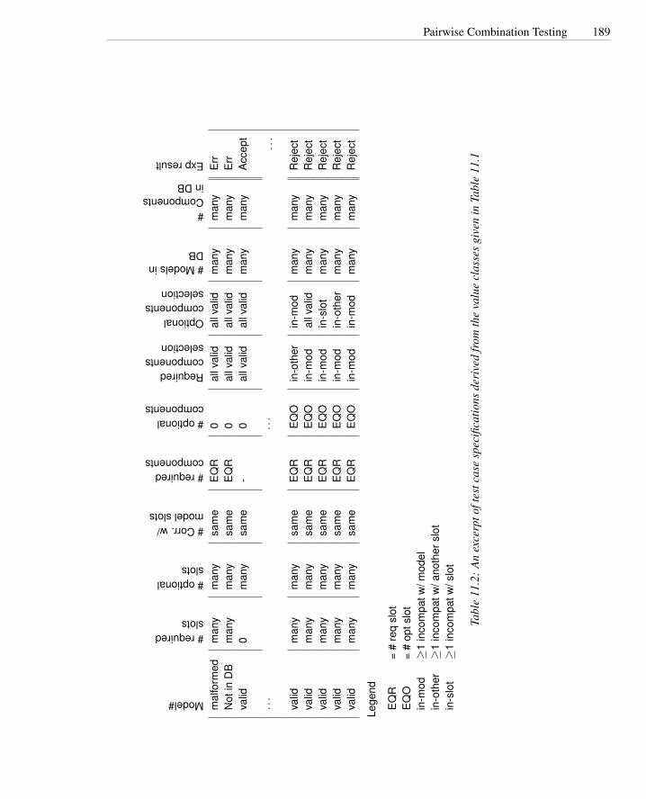
Pairwise Combination Testing 189
Model#
#requiredslots
#optionalslots
#Corr.w/modelslots
#requiredcomponents
#optionalcomponents
Requiredcomponentsselection
Optionalcomponentsselection
#ModelsinDB
#ComponentsinDB
Expresult
mal
form
edm
any
man
ysa
me
EQ
R0
allv
alid
allv
alid
man
ym
any
Err
Not
inD
Bm
any
man
ysa
me
EQ
R0
allv
alid
allv
alid
man
ym
any
Err
valid
0m
any
sam
e-
0al
lval
idal
lval
idm
any
man
yA
ccep
t
···
···
...
valid
man
ym
any
sam
eE
QR
EQ
Oin
-oth
erin
-mod
man
ym
any
Rej
ect
valid
man
ym
any
sam
eE
QR
EQ
Oin
-mod
allv
alid
man
ym
any
Rej
ect
valid
man
ym
any
sam
eE
QR
EQ
Oin
-mod
in-s
lot
man
ym
any
Rej
ect
valid
man
ym
any
sam
eE
QR
EQ
Oin
-mod
in-o
ther
man
ym
any
Rej
ect
valid
man
ym
any
sam
eE
QR
EQ
Oin
-mod
in-m
odm
any
man
yR
ejec
t
Lege
nd
EQ
R=
#re
qsl
otE
QO
=#
opts
lot
in-m
od≥
1in
com
patw
/mod
elin
-oth
er≥
1in
com
patw
/ano
ther
slot
in-s
lot
≥1
inco
mpa
tw/s
lot
Tabl
e11
.2:
An
exce
rpto
ftes
tcas
esp
ecifi
catio
nsde
rive
dfr
omth
eva
lue
clas
ses
give
nin
Tabl
e11
.1

190 Combinatorial Testing
Display Modefull-graphicstext-onlylimited-bandwidth
LanguageEnglishFrenchSpanishPortuguese
FontsMinimalStandardDocument-loaded
ColorMonochromeColor-map16-bitTrue-color
Screen sizeHand-heldLaptopFull-size
Table 11.3: Parameters and values controlling Chipmunk Web site display
reflect real constraints in the application domain, and eliminate many redundant com-binations (for example, the “error” entries in category-partition testing). It is less sat-isfactory when, lacking real constraints from the application domain, the test designeris forced to add arbitrary constraints (e.g., “single” entries in the category-partitionmethod) whose sole purpose is to reduce the number of combinations.
Consider the parameters that control the Chipmunk Web site display, shown in Ta-ble 11.3. Exhaustive enumeration produces 432 combinations, which is too many if thetest results (e.g., judging readability) involve human judgment. While the test designermight hypothesize some constraints, such as observing that monochrome displays arelimited mostly to hand-held devices, radical reductions require adding several “single”and “property” constraints without any particular rationale.
Exhaustive enumeration of all n-way combinations of value classes for n param-eters, on the one hand, and coverage of individual classes, on the other, are only theextreme ends of a spectrum of strategies for generating combinations of classes. Be-tween them lie strategies that generate all pairs of classes for different parameters,all triples, and so on. When it is reasonable to expect some potential interaction be-tween parameters (so coverage of individual value classes is deemed insufficient), butcovering all combinations is impractical, an attractive alternative is to generate k-waycombinations for k < n, typically pairs or triples.
How much does generating possible pairs of classes save, compared to generatingall combinations? We have already observed that the number of all combinations isthe product of the number of classes for each parameter, and that this product growsexponentially with the number of parameters. It turns out that the number of combina-tions needed to cover all possible pairs of values grows only logarithmically with thenumber of parameters — an enormous saving.
A simple example may suffice to gain some intuition about the efficiency of gener-ating tuples that cover pairs of classes, rather than all combinations. Suppose we havejust the three parameters display mode, screen size, and fonts from Table 11.3. If weconsider only the first two, display mode and screen size, the set of all pairs and the set
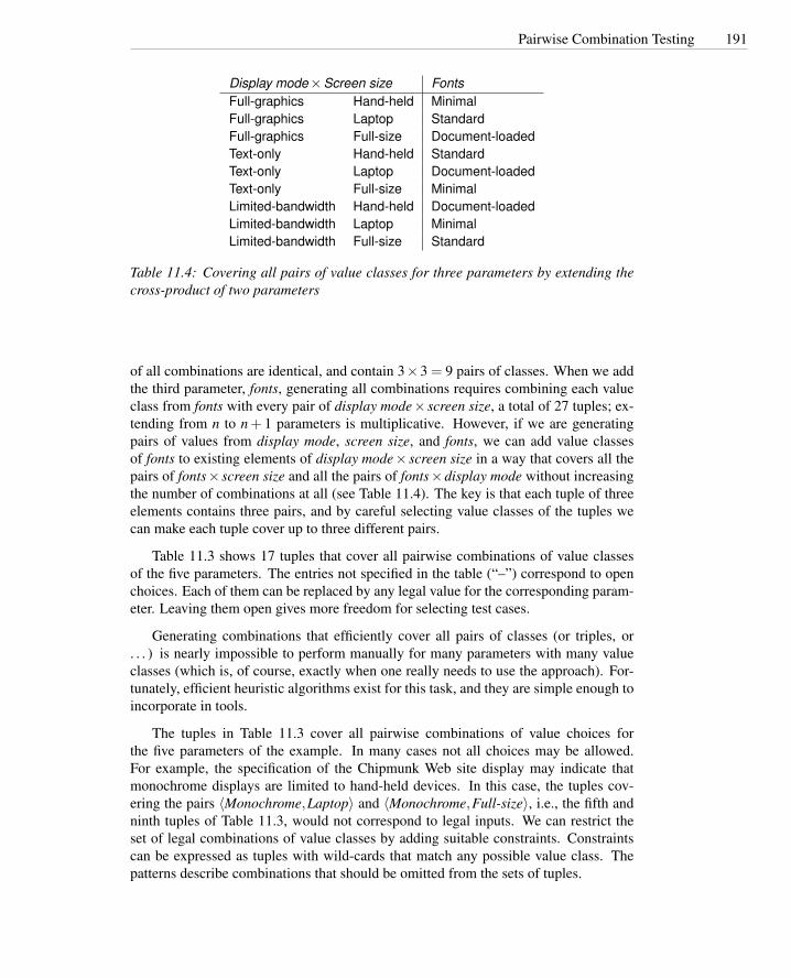
Pairwise Combination Testing 191
Display mode×Screen size FontsFull-graphics Hand-held MinimalFull-graphics Laptop StandardFull-graphics Full-size Document-loadedText-only Hand-held StandardText-only Laptop Document-loadedText-only Full-size MinimalLimited-bandwidth Hand-held Document-loadedLimited-bandwidth Laptop MinimalLimited-bandwidth Full-size Standard
Table 11.4: Covering all pairs of value classes for three parameters by extending thecross-product of two parameters
of all combinations are identical, and contain 3×3 = 9 pairs of classes. When we addthe third parameter, fonts, generating all combinations requires combining each valueclass from fonts with every pair of display mode× screen size, a total of 27 tuples; ex-tending from n to n + 1 parameters is multiplicative. However, if we are generatingpairs of values from display mode, screen size, and fonts, we can add value classesof fonts to existing elements of display mode× screen size in a way that covers all thepairs of fonts× screen size and all the pairs of fonts×display mode without increasingthe number of combinations at all (see Table 11.4). The key is that each tuple of threeelements contains three pairs, and by careful selecting value classes of the tuples wecan make each tuple cover up to three different pairs.
Table 11.3 shows 17 tuples that cover all pairwise combinations of value classesof the five parameters. The entries not specified in the table (“–”) correspond to openchoices. Each of them can be replaced by any legal value for the corresponding param-eter. Leaving them open gives more freedom for selecting test cases.
Generating combinations that efficiently cover all pairs of classes (or triples, or. . . ) is nearly impossible to perform manually for many parameters with many valueclasses (which is, of course, exactly when one really needs to use the approach). For-tunately, efficient heuristic algorithms exist for this task, and they are simple enough toincorporate in tools.
The tuples in Table 11.3 cover all pairwise combinations of value choices forthe five parameters of the example. In many cases not all choices may be allowed.For example, the specification of the Chipmunk Web site display may indicate thatmonochrome displays are limited to hand-held devices. In this case, the tuples cov-ering the pairs 〈Monochrome,Laptop〉 and 〈Monochrome,Full-size〉, i.e., the fifth andninth tuples of Table 11.3, would not correspond to legal inputs. We can restrict theset of legal combinations of value classes by adding suitable constraints. Constraintscan be expressed as tuples with wild-cards that match any possible value class. Thepatterns describe combinations that should be omitted from the sets of tuples.

192 Combinatorial Testing
Language Color Display Mode Fonts Screen SizeEnglish Monochrome Full-graphics Minimal Hand-heldEnglish Color-map Text-only Standard Full-sizeEnglish 16-bit Limited-bandwidth – Full-sizeEnglish True-color Text-only Document-loaded LaptopFrench Monochrome Limited-bandwidth Standard LaptopFrench Color-map Full-graphics Document-loaded Full-sizeFrench 16-bit Text-only Minimal –French True-color – – Hand-heldSpanish Monochrome – Document-loaded Full-sizeSpanish Color-map Limited-bandwidth Minimal Hand-heldSpanish 16-bit Full-graphics Standard LaptopSpanish True-color Text-only – Hand-heldPortuguese Monochrome Text-only – –Portuguese Color-map – Minimal LaptopPortuguese 16-bit Limited-bandwidth Document-loaded Hand-heldPortuguese True-color Full-graphics Minimal Full-sizePortuguese True-color Limited-bandwidth Standard Hand-held
Table 11.5: Covering all pairs of value classes for the five parameters
For example, the constraints
OMIT〈∗,∗,∗,Monochrome,Laptop〉
OMIT〈∗,∗,∗,Monochrome,Full-size〉
indicate that tuples containing the pair 〈Monochrome,Hand-held〉 as values for thefourth and fifth parameter are not allowed in the relation of Table 11.3.
Tuples that cover all pairwise combinations of value classes without violating theconstraints can be generated by simply removing the illegal tuples and adding legaltuples that cover the removed pairwise combinations. Open choices must be boundconsistently in the remaining tuples, e.g., tuple
〈Portuguese,Monochrome,Text-only, -, -〉
must become
〈Portuguese,Monochrome,Text-only, -,Hand-held〉
Constraints can also be expressed with sets of tables to indicate only the legal com-binations, as illustrated in Table 11.6, where the first table indicates that the value classHand-held for parameter Screen can be combined with any value class of parameterColor, including Monochrome, while the second table indicates that the value classesLaptop and Full-size for parameter Screen size can be combined with all values classesexcept Monochrome for parameter Color.

Pairwise Combination Testing 193
Hand-held devices
Display Modefull-graphicstext-onlylimited-bandwidth
LanguageEnglishFrenchSpanishPortuguese
FontsMinimalStandardDocument-loaded
ColorColor-map16-bitTrue-color
Screen sizeHand-held
Laptop and Full-size devices
Display Modefull-graphicstext-onlylimited-bandwidth
LanguageEnglishFrenchSpanishPortuguese
FontsMinimalStandardDocument-loaded
ColorMonochromeColor-map16-bitTrue-color
Screen sizeLaptopFull size
Table 11.6: Pairs of tables that indicate valid value classes for the Chipmunk Web sitedisplay
If constraints are expressed as a set of tables that give only legal combinations,tuples can be generated without changing the heuristic. Although the two approachesexpress the same constraints, the number of generated tuples can be different, sincedifferent tables may indicate overlapping pairs and thus result in a larger set of tuples.Other ways of expressing constraints may be chosen according to the characteristics ofthe specification and the preferences of the test designer.
So far we have illustrated the combinatorial approach with pairwise coverage. Aspreviously mentioned, the same approach can be applied for triples or larger combina-tions. Pairwise combinations may be sufficient for some subset of the parameters, butnot enough to uncover potential interactions among other parameters. For example, inthe Chipmunk display example, the fit of text fields to screen areas depends on the com-bination of language, fonts, and screen size. Thus, we may prefer exhaustive coverageof combinations of these three parameters, but be satisfied with pairwise coverage of

194 Combinatorial Testing
other parameters. In this case, we first generate tuples of classes from the parameters tobe most thoroughly covered, and then extend these with the parameters which requireless coverage.
11.4 Catalog-Based Testing
The test design techniques described above require judgment in deriving value classes.Over time, an organization can build experience in making these judgments well. Gath-ering this experience in a systematic collection can speed up the process and routinizemany decisions, reducing human error and better focusing human effort. Catalogscapture the experience of test designers by listing all cases to be considered for eachpossible type of variable that represents logical inputs, outputs, and status of the com-putation. For example, if the computation uses a variable whose value must belong to arange of integer values, a catalog might indicate the following cases, each correspond-ing to a relevant test case:
1. The element immediately preceding the lower bound of the interval
2. The lower bound of the interval
3. A non-boundary element within the interval
4. The upper bound of the interval
5. The element immediately following the upper bound
The catalog would in this way cover the intuitive cases of erroneous conditions(cases 1 and 5), boundary conditions (cases 2 and 4), and normal conditions (case 3).
The catalog-based approach consists in unfolding the specification, i.e., decompos-ing the specification into elementary items, deriving an initial set of test case specifica-tions from pre-conditions, post-conditions, and definitions, and completing the set oftest case specifications using a suitable test catalog.
STEP 1: identify elementary items of the specification The initial specification istransformed into a set of elementary items. Elementary items belong to a small set ofbasic types:
Preconditions represent the conditions on the inputs that must be satisfied before in-vocation of the unit under test. Preconditions may be checked either by the unitunder test (validated preconditions) or by the caller (assumed preconditions).
Postconditions describe the result of executing the unit under test.
Variables indicate the values on which the unit under test operates. They can be input,output, or intermediate values.
Operations indicate the main operations performed on input or intermediate variablesby the unit under test
Definitions are shorthand used in the specification

Catalog-Based Testing 195
cgi decode: Function cgi decode translates a cgi-encoded string to a plain ASCIIstring, reversing the encoding applied by the common gateway interface (CGI)of most Web servers.
CGI translates spaces to ‘+’, and translates most other non-alphanumeric charac-ters to hexadecimal escape sequences. cgi decode maps ‘+’ to ‘ ’, “%xy” (where xand y are hexadecimal digits) to to the corresponding ASCII character, and otheralphanumeric characters to themselves.
INPUT: encoded A string of characters, representing the input CGI sequence. It cancontain:
• alphanumeric characters
• the character ‘+’
• the substring “%xy”, where x and y are hexadecimal digits.
encoded is terminated by a null character.
OUTPUT: decoded A string containing the plain ASCII characters corresponding tothe input CGI sequence.
• Alphanumeric characters are copied into the output in the correspondingposition
• A blank is substituted for each ‘+’ character in the input.
• A single ASCII character with hexadecimal value xy16 is substituted for eachsubstring “%xy” in the input.
OUTPUT: return value cgi decode returns
• 0 for success
• 1 if the input is malformed
Figure 11.2: An informal (and imperfect) specification of C function cgi decode
As in other approaches that begin with an informal description, it is not possible togive a precise recipe for extracting the significant elements. The result will depend onthe capability and experience of the test designer.
Consider the informal specification of a function for converting URL-encoded formdata into the original data entered through an html form. An informal specification isgiven in Figure 11.2.2
The informal description of cgi decode uses the concept of hexadecimal digit, hex-adecimal escape sequence, and element of a cgi encoded sequence. This leads to theidentification of the following three definitions:
2The informal specification is ambiguous and inconsistent, i.e., it is the kind of spec one is most likely toencounter in practice.

196 Combinatorial Testing
DEF 1 hexadecimal digits are: ‘0’, ‘1’, ‘2’, ‘3’, ‘4’, ‘5’, ‘6’, ‘7’, ‘8’, ‘9’, ‘A’, ‘B’, ‘C’,‘D’, ‘E’, ‘F’, ‘a’, ‘b’, ‘c’, ‘d’, ‘e’, ‘f’
DEF 2 a CGI-hexadecimal is a sequence of three characters: “%xy”, where x and yare hexadecimal digits
DEF 3 a CGI item is either an alphanumeric character, or character ‘+’, or a CGI-hexadecimal
In general, every concept introduced in the description to define the problem canbe represented as a definition.
The description of cgi decode mentions some elements that are inputs and outputsof the computation. These are identified as the following variables:
VAR 1 Encoded: string of ASCII characters
VAR 2 Decoded: string of ASCII characters
VAR 3 return value: Boolean
Note the distinction between a variable and a definition. Encoded and decoded areactually used or computed, while hexadecimal digits, CGI-hexadecimal, and CGI itemare used to describe the elements but are not objects in their own right. Although notstrictly necessary for the problem specification, explicit identification of definitions canhelp in deriving a richer set of test cases.
The description of cgi decode indicates some conditions that must be satisfied uponinvocation, represented by the following preconditions:
PRE 1 (Assumed) the input string Encoded is a null-terminated string of characters.
PRE 2 (Validated) the input string Encoded is a sequence of CGI items.
In general, preconditions represent all the conditions that should be true for theintended functioning of a module. A condition is labeled as validated if it is checkedby the module (in which case a violation has a specified effect, e.g., raising an exceptionor returning an error code). Assumed preconditions must be guaranteed by the caller,and the module does not guarantee a particular behavior in case they are violated.
The description of cgi decode indicates several possible results. These can be rep-resented as a set of postconditions:
POST 1 if the input string Encoded contains alphanumeric characters, they are copiedto the corresponding position in the output string.
POST 2 if the input string Encoded contains ‘+’ characters, they are replaced byASCII space characters in the corresponding positions in the output string.
POST 3 if the input string Encoded contains CGI-hexadecimals, they are replaced bythe corresponding ASCII characters.
POST 4 if the input string Encoded is a valid sequence, cgi decode returns 0.

Catalog-Based Testing 197
POST 5 if the input string Encoded contains a malformed CGI-hexadecimal, i.e., asubstring “%xy”, where either x or y is absent or are not hexadecimal digits,cgi decode returns 1
POST 6 if the input string Encoded contains any illegal character, cgi decode returns1.
The postconditions should, together, capture all the expected outcomes of the mod-ule under test. When there are several possible outcomes, it is possible to capture all ofthem in one complex postcondition or in several simple postconditions; here we havechosen a set of simple contingent postconditions, each of which captures one case. Theinformal specification does not distinguish among cases of malformed input strings,but the test designer may make further distinctions while refining the specification.
Although the description of cgi decode does not mention explicitly how the resultsare obtained, we can easily deduce that it will be necessary to scan the input sequence.This is made explicit in the following operation:
OP 1 Scan the input string Encoded.
In general, a description may refer either explicitly or implicitly to elementary oper-ations which help to clearly describe the overall behavior, like definitions help to clearlydescribe variables. As with variables, they are not strictly necessary for describing therelation between pre- and postconditions, but they serve as additional information forderiving test cases.
The result of step 1 for cgi decode is summarized in Figure 11.3.
STEP 2 Derive a first set of test case specifications from preconditions, postcon-ditions and definitions The aim of this step is to explicitly describe the partition ofthe input domain:
Validated Preconditions: A simple precondition, i.e., a precondition that is expressedas a simple Boolean expression without and or or, identifies two classes of input:values that satisfy the precondition and values that do not. We thus derive twotest case specifications.
A compound precondition, given as a Boolean expression with and or or, iden-tifies several classes of inputs. Although in general one could derive a differenttest case specification for each possible combination of truth values of the ele-mentary conditions, usually we derive only a subset of test case specificationsusing the modified condition decision coverage (MC/DC) approach, which isillustrated in Section 14.3 and in Chapter 12. In short, we derive a set of com-binations of elementary conditions such that each elementary condition can beshown to independently affect the outcome of each decision. For each elemen-tary condition C, there are two test case specifications in which the truth valuesof all conditions except C are the same, and the compound condition as a wholeevaluates to True for one of those test cases and False for the other.

198 Combinatorial Testing
PRE 1 (Assumed) the input string Encoded is a null-terminated string of charac-ters
PRE 2 (Validated) the input string Encoded is a sequence of CGI itemsPOST 1 if the input string Encoded contains alphanumeric characters, they are
copied to the output string in the corresponding positions.POST 2 if the input string Encoded contains ‘+’ characters, they are replaced in the
output string by ASCII space characters in the corresponding positionsPOST 3 if the input string Encoded contains CGI-hexadecimals, they are replaced
by the corresponding ASCII characters.POST 4 if the input string Encoded is well-formed, cgi decode returns 0POST 5 if the input string Encoded contains a malformed CGI hexadecimal, i.e.,
a substring “%xy”, where either x or y are absent or are not hexadecimaldigits, cgi decode returns 1
POST 6 if the input string Encoded contains any illegal character, cgi decode re-turns 1
VAR 1 Encoded: a string of ASCII charactersVAR 2 Decoded: a string of ASCII charactersVAR 3 Return value: a BooleanDEF 1 hexadecimal digits are ASCII characters in range [‘0’ .. ‘9’, ‘A’ .. ‘F’, ‘a’
.. ‘f’]DEF 2 CGI-hexadecimals are sequences “%xy”, where x and y are hexadecimal
digitsDEF 3 A CGI item is an alphanumeric character, or ‘+’, or a CGI-hexadecimalOP 1 Scan Encoded
Figure 11.3: Elementary items of specification cgi decode

Catalog-Based Testing 199
Assumed Preconditions: We do not derive test case specifications for cases that vio-late assumed preconditions, since there is no defined behavior and thus no wayto judge the success of such a test case. We also do not derive test cases whenthe whole input domain satisfies the condition, since test cases for these wouldbe redundant. We generate test cases from assumed preconditions only whenthe MC/DC criterion generates more than one class of valid combinations (i.e.,when the condition is a logical disjunction of more elementary conditions).
Postconditions: In all cases in which postconditions are given in a conditional form,the condition is treated like a validated precondition, i.e., we generate a test casespecification for cases that satisfy and cases that do not satisfy the condition.
Definition: Definitions that refer to input or output values and are given in conditionalform are treated like validated preconditions. We generate a set of test casespecification for cases that satisfy and cases that do not satisfy the specification.The test cases are generated for each variable that refers to the definition.
The elementary items of the specification identified in step 1 are scanned sequen-tially and a set of test cases is derived applying these rules. While scanning the speci-fications, we generate test case specifications incrementally. When new test case spec-ifications introduce a refinement of an existing case, or vice versa, the more generalcase becomes redundant and can be eliminated. For example, if an existing test casespecification requires a non-empty set, and we have to add two test case specificationsthat require a size that is a power of two and one which is not, the existing test casespecification can be deleted because the new test cases must include a non-empty set.
Scanning the elementary items of the cgi decode specification given in Figure 11.3,we proceed as follows:
PRE 1: The first precondition is a simple assumed precondition. We do not generateany test case specification. The only condition would be “encoded: a null termi-nated string of characters,” but this matches every test case and thus it does notidentify a useful test case specification.
PRE 2: The second precondition is a simple validated precondition. We generate twotest case specifications, one that satisfies the condition and one that does not:
TC-PRE2-1 Encoded: a sequence of CGI items
TC-PRE2-2 Encoded: not a sequence of CGI items
All postconditions in the cgi decode specification are given in a conditional form witha simple condition. Thus, we generate two test case specifications for each of them.The generated test case specifications correspond to a case that satisfies the conditionand a case that violates it.
POST 1:
TC-POST1-1 Encoded: contains one or more alphanumeric characters
TC-POST1-2 Encoded: does not contain any alphanumeric characters

200 Combinatorial Testing
POST 2:
TC-POST2-1 Encoded: contains one or more character ‘+’
TC-POST2-2 Encoded: does not any contain character ‘+’
POST 3:
TC-POST3-1 Encoded: contains one or more CGI-hexadecimals
TC-POST3-2 Encoded: does not contain any CGI-hexadecimal
POST 4: We do not generate any new useful test case specifications, because the twospecifications are already covered by the specifications generated from PRE 2.
POST 5: We generate only the test case specification that satisfies the condition. Thetest case specification that violates the specification is redundant with respect tothe test case specifications generated from POST 3
TC-POST5-1 : Encoded contains one or more malformed CGI-hexadecimals
POST 6: As for POST 5, we generate only the test case specification that satisfies thecondition. The test case specification that violates the specification is redundantwith respect to several of the test case specifications generated so far.
TC-POST6-1 Encoded: contains one or more illegal characters
None of the definitions in the specification of cgi decode is given in conditional terms,and thus no test case specifications are generated at this step.
The test case specifications generated from postconditions refine test case specifi-cation TC-PRE2-1, which can thus be eliminated from the checklist. The result of step2 for cgi decode is summarized in Figure 11.4.
STEP 3 Complete the test case specifications using catalogs The aim of this stepis to generate additional test case specifications from variables and operations used ordefined in the computation. The catalog is scanned sequentially. For each entry of thecatalog we examine the elementary components of the specification and add cases tocover all values in the catalog. As when scanning the test case specifications duringstep 2, redundant test case specifications are eliminated.
Table 11.7 shows a simple catalog that we will use for the cgi decode example. Acatalog is structured as a list of kinds of elements that can occur in a specification. Eachcatalog entry is associated with a list of generic test case specifications appropriate forthat kind of element. We scan the specification for elements whose type is compatiblewith the catalog entry, then generate the test cases defined in the catalog for that entry.For example, the catalog of Table 11.7 contains an entry for Boolean variables. Whenwe find a Boolean variable in the specification, we instantiate the catalog entry bygenerating two test case specifications, one that requires a True value and one thatrequires a False value.
Each generic test case in the catalog is labeled in, out, or in/out, meaning that atest case specification is appropriate if applied to an input variable, or to an output

Catalog-Based Testing 201
PRE 2 Validated) the input string Encoded is a sequence of CGI items[TC-PRE2-2] Encoded: not a sequence of CGI items
POST 1 if the input string Encoded contains alphanumeric characters, they are copiedto the output string in the corresponding positions
[TC-POST1-1] Encoded: contains alphanumeric characters[TC-POST1-2] Encoded: does not contain alphanumeric characters
POST 2 if the input string Encoded contains ‘+’ characters, they are replaced in theoutput string by ‘ ’ in the corresponding positions
[TC-POST2-1] Encoded: contains ‘+’[TC-POST2-2] Encoded: does not contain ‘+’
POST 3 if the input string Encoded contains CGI-hexadecimals, they are replaced bythe corresponding ASCII characters.
[TC-POST3-1] Encoded: contains CGI-hexadecimals[TC-POST3-2] Encoded: does not contain a CGI-hexadecimal
POST 4 if the input string Encoded is well-formed, cgi decode returns 0
POST 5 if the input string Encoded contains a malformed CGI-hexadecimal, i.e., asubstring “%xy”, where either x or y are absent or non hexadecimal digits,cgi decode returns 1
[TC-POST5-1] Encoded: contains malformed CGI-hexadecimals
POST 6 if the input string Encoded contains any illegal character, cgi decode returnsa positive value
[TC-POST6-1] Encoded: contains illegal characters
VAR 1 Encoded: a string of ASCII characters
VAR 2 Decoded: a string of ASCII characters
VAR 3 Return value: a Boolean
DEF 1 hexadecimal digits are in range [’0’ .. ‘9’, ‘A’ .. ‘F’, ‘a’ .. ‘f’]
DEF 2 CGI-hexadecimals are sequences ‘%xy’, where x and y are hexadecimal dig-its
DEF 3 CGI items are either alphanumeric characters, or ‘+’, or CGI-hexadecimals
OP 1 Scan Encoded
Figure 11.4: Test case specifications for cgi decode generated after step 2.

202 Combinatorial Testing
Boolean[in/out] True[in/out] False
Enumeration[in/out] Each enumerated value[in] Some value outside the enumerated set
Range L . . .U[in] L−1 (the element immediately preceding the lower bound)[in/out] L (the lower bound)[in/out] A value between L and U[in/out] U (the upper bound)[in] U +1 (the element immediately following the upper bound)
Numeric Constant C[in/out] C (the constant value)[in] C−1 (the element immediately preceding the constant value)[in] C +1 (the element immediately following the constant value)[in] Any other constant compatible with C
Non-Numeric Constant C[in/out] C (the constant value)[in] Any other constant compatible with C[in] Some other compatible value
Sequence[in/out] Empty[in/out] A single element[in/out] More than one element[in/out] Maximum length (if bounded) or very long[in] Longer than maximum length (if bounded)[in] Incorrectly terminated
Scan with action on elements P[in] P occurs at beginning of sequence[in] P occurs in interior of sequence[in] P occurs at end of sequence[in] PP occurs contiguously[in] P does not occur in sequence[in] pP where p is a proper prefix of P[in] Proper prefix p occurs at end of sequence
Table 11.7: Part of a simple test catalog.
Catalog-Based Testing 203
variable, or in both cases. In general, erroneous values should be used when testingthe behavior of the system with respect to input variables, but are usually impossibleto produce when testing the behavior of the system with respect to output variables.For example, when the value of an input variable can be chosen from a set of values,it is important to test the behavior of the system for all enumerated values and somevalues outside the enumerated set, as required by entry ENUMERATION of the catalog.However, when the value of an output variable belongs to a finite set of values, weshould derive a test case for each possible outcome, but we cannot derive a test casefor an impossible outcome, so entry ENUMERATION of the catalog specifies that thechoice of values outside the enumerated set is limited to input variables. Intermediatevariables, if present, are treated like output variables.
Entry Boolean of the catalog applies to Return value (VAR 3). The catalog re-quires a test case that produces the value True and one that produces the value False .Both cases are already covered by test cases TC-PRE2-1 and TC-PRE2-2 generated forprecondition PRE 2, so no test case specification is actually added.
Entry Enumeration of the catalog applies to any variable whose values are chosenfrom an explicitly enumerated set of values. In the example, the values of CGI item(DEF 3) and of improper CGI hexadecimals in POST 5 are defined by enumeration.Thus, we can derive new test case specifications by applying entry enumeration toPOST 5 and to any variable that can contain CGI items.
The catalog requires creation of a test case specification for each enumerated valueand for some excluded values. For encoded, which should consist of CGI-items as de-fined in DEF 3, we generate a test case specification where a CGI-item is an alphanu-meric character, one where it is the character ‘+’, one where it is a CGI-hexadecimal,and one where it is an illegal value. We can easily ascertain that all the required casesare already covered by test case specifications for TC-POST1-1, TC-POST1-2, TC-POST2-1, TC-POST2-2, TC-POST3-1, and TC-POST3-2, so any additional test casespecifications would be redundant.
From the enumeration of malformed CGI-hexadecimals in POST 5, we derive thefollowing test cases: %y, %x, %ky, %xk, %xy (where x and y are hexadecimal digitsand k is not). Note that the first two cases, %x (the second hexadecimal digit is missing)and %y (the first hexadecimal digit is missing) are identical, and %x is distinct from%xk only if %x are the last two characters in the string. A test case specificationrequiring a correct pair of hexadecimal digits (%xy) is a value out of the range of theenumerated set, as required by the catalog.
The added test case specifications are:
TC-POST5-2 encoded: terminated with %x, where x is a hexadecimal digit
TC-POST5-3 encoded: contains %ky, where k is not a hexadecimal digit and y is ahexadecimal digit.
TC-POST5-4 encoded: contains %xk, where x is a hexadecimal digit and k is not.
The test case specification corresponding to the correct pair of hexadecimal digits isredundant, having already been covered by TC-POST3-1. The test case TC-POST5-1
204 Combinatorial Testing
can now be eliminated because it is more general than the combination of TC-POST5-2, TC-POST5-3, and TC-POST5-4.
Entry Range applies to any variable whose values are chosen from a finite range. Inthe example, ranges appear three times in the definition of hexadecimal digit. Rangesalso appear implicitly in the reference to alphanumeric characters (the alphabetic andnumeric ranges from the ASCII character set) in DEF 3. For hexadecimal digits we willtry the special values ‘/’ and ‘:’ (the characters that appear before ‘0’ and after ‘9’ in theASCII encoding), the values ‘0’ and ’9’ (upper and lower bounds of the first interval),some value between ’0’ and ‘9’; similarly ‘@’, ‘G’, ‘A’, ‘F’, and some value between’A’ and ‘F’ for the second interval; and ‘‘’, ‘g’, ‘a’, ‘f’, and some value between ‘a’and ‘f’ for the third interval.
These values will be instantiated for variable encoded, and result in 30 additionaltest case specifications (5 values for each subrange, giving 15 values for each hexadec-imal digit and thus 30 for the two digits of CGI-hexadecimal). The full set of test casespecifications is shown in Table 11.8. These test case specifications are more specificthan (and therefore replace) test case specifications TC-POST3-1, TC-POST5-3, andTC-POST5-4.
For alphanumeric characters we will similarly derive boundary, interior and ex-cluded values, which result in 15 additional test case specifications, also given in Ta-ble 11.8. These test cases are more specific than (and therefore replace) TC-POST1-1,TC-POST1-2, and TC-POST6-1.
Entry Numeric Constant does not apply to any element of this specification.Entry Non-Numeric Constant applies to ‘+’ and ‘%’, occurring in DEF 3 and DEF
2 respectively. Six test case specifications result, but all are redundant.Entry Sequence applies to encoded (VAR 1), decoded (VAR 2), and cgi-item (DEF
2). Six test case specifications result for each, of which only five are mutually non-redundant and not already in the list. From VAR 1 (encoded) we generate test casespecifications requiring an empty sequence, a sequence containing a single element,and a very long sequence. The catalog entry requiring more than one element generatesa redundant test case specification, which is discarded. We cannot produce reasonabletest cases for incorrectly terminated strings (the behavior would vary depending on thecontents of memory outside the string), so we omit that test case specification.
All test case specifications that would be derived for decoded (VAR 2) would beredundant with respect to test case specifications derived for encoded (VAR 1).
From CGI-hexadecimal (DEF 2) we generate two additional test case specificationsfor variable encoded: a sequence that terminates with ‘%’ (the only way to producea one-character subsequence beginning with ‘%’) and a sequence containing ‘%xyz’,where x, y, and z are hexadecimal digits.
Entry Scan applies to Scan Encoded (OP 1) and generates 17 test case specifica-tions. Three test case specifications (alphanumeric, ‘+’, and CGI item) are generatedfor each of the first 5 items of the catalog entry. One test case specification is generatedfor each of the last two items of the catalog entry when Scan is applied to CGI item.The last two items of the catalog entry do not apply to alphanumeric characters and‘+’, since they have no non-trivial prefixes. Seven of the 17 are redundant. The tengenerated test case specifications are summarized in Table 11.8.

Catalog-Based Testing 205
TC-POST2-1 Encoded contains character ‘+’TC-POST2-2 Encoded does not contain char-
acter ‘+’TC-POST3-2 Encoded does not contain a
CGI-hexadecimalTC-POST5-2 Encoded terminates with %xTC-VAR1-1 Encoded is the empty sequenceTC-VAR1-2 Encoded is a sequence consist-
ing of a single characterTC-VAR1-3 Encoded is a very long
sequence
Encoded contains . . .TC-DEF2-1 . . . ‘%/y’TC-DEF2-2 . . . ‘%0y’TC-DEF2-3 . . . ‘%xy’, with x in [‘1’..‘8’]TC-DEF2-4 . . . ‘%9y’TC-DEF2-5 . . . ‘%:y’TC-DEF2-6 . . . ‘%@y’TC-DEF2-7 . . . ‘%Ay’TC-DEF2-8 . . . ‘%xy’, with x in [‘B’..‘E’]TC-DEF2-9 . . . ‘%Fy’TC-DEF2-10 . . . ‘%Gy’TC-DEF2-11 . . . ‘%‘y’TC-DEF2-12 . . . ‘%ay’TC-DEF2-13 . . . ‘%xy’, with x in [‘b’..‘e’]TC-DEF2-14 . . . ‘%fy’TC-DEF2-15 . . . ‘%gy’TC-DEF2-16 . . . ‘%x/’TC-DEF2-17 . . . ‘%x0’TC-DEF2-18 . . . ‘%xy’, with y in [‘1’..‘8’]TC-DEF2-19 . . . ‘%x9’TC-DEF2-20 . . . ‘%x:’TC-DEF2-21 . . . ‘%x@’TC-DEF2-22 . . . ‘%xA’TC-DEF2-23 . . . ‘%xy’, with y in [‘B’..‘E’]
TC-DEF2-24 . . . ‘%xF’TC-DEF2-25 . . . ‘%xG’TC-DEF2-26 . . . ‘%x‘’TC-DEF2-27 . . . ‘%xa’TC-DEF2-28 . . . ‘%xy’, with y in [‘b’..‘e’]TC-DEF2-29 . . . ‘%xf’TC-DEF2-30 . . . ‘%xg’TC-DEF2-31 . . . ‘%$’TC-DEF2-32 . . . ‘%xyz’TC-DEF3-1 . . . ‘/’TC-DEF3-2 . . . ‘0’TC-DEF3-3 . . . c, with c in [‘1’..‘8’]TC-DEF3-4 . . . ‘9’TC-DEF3-5 . . . ‘:’TC-DEF3-6 . . . ‘@’TC-DEF3-7 . . . ‘A’TC-DEF3-8 . . . a, with a in [‘B’..‘Y’]TC-DEF3-9 . . . ‘Z’TC-DEF3-10 . . . ‘[’TC-DEF3-11 . . . ‘‘’TC-DEF3-12 . . . ‘a’TC-DEF3-13 . . . a, with a in [‘b’..‘y’]TC-DEF3-14 . . . ‘z’TC-DEF3-15 . . . ‘{’TC-OP1-1 . . . ‘ˆa’TC-OP1-2 . . . ‘ˆ+’TC-OP1-3 . . . ˆ%xy’TC-OP1-4 . . . ‘a$’TC-OP1-5 . . . ‘+$’TC-OP1-6 . . . ‘%xy$’TC-OP1-7 . . . ‘aa’TC-OP1-8 . . . ‘++’TC-OP1-9 . . . ‘%xy%zw’TC-OP1-10 . . . ‘%x%yz’
Where w,x,y,z are hexadecimal digits, a is an alphanumeric character, ˆ represents the beginning of thestring, and $ represents the end of the string.
Table 11.8: Summary table: Test case specifications for cgi decode generated with a catalog.
206 Combinatorial Testing
Test catalogs, like other check lists used in test and analysis (e.g., inspection checklists), are an organizational asset that can be maintained and enhanced over time. Agood test catalog will be written precisely and suitably annotated to resolve ambiguity.Catalogs should also be specialized to an organization and application domain, typi-cally using a process such as defect causal analysis or root cause analysis (Chapters20 and 18). Entries are added to detect particular classes of faults that have been en-countered frequently or have been particularly costly to remedy in previous projects.Refining check lists is a typical activity carried out as part of process improvement.When a test reveals a program fault, it is useful to make a note of which catalog entriesthe test case originated from, as an aid to measuring the effectiveness of catalog entries.Catalog entries that are not effective should be removed.
Open research issues
In the last decades, structured languages replaced natural language in software specifi-cations, and today unstructured specifications written in natural language are becomingless common. Unstructured natural language specifications are still commonly used ininformal development environments that lack expertise and tools, and often do notadopt rigorous development methodologies. Deriving structure from natural languageis not a main focus of the research community, which pays more attention to exploitingformal and semi-formal models that may be produced in the course of a project.
Combinatorial methods per se is a niche research area that attracts relatively littleattention from the research community. One issue that has received too little atten-tion to date is adapting combinatorial test techniques to cope with constantly changingspecifications.
Further Reading
Category partition testing is described by Ostrand and Balcer [OB88]. The combina-torial approach described in this chapter is due to Cohen, Dalal, Fredman, and Patton[CDFP97]; the algorithm described by Cohen et al. is patented by Bellcore. Catalog-based testing of subsystems is described in Marick’s The Craft of Software Testing[Mar97].
Related topics
Readers interested in learning additional functional testing techniques may continuewith the next Chapter that describes model-based testing techniques. Readers inter-ested in the complementarities between functional and structural testing as well asreaders interested in testing the decision structures and control and data flow graphsmay continue with the following chapters that describe structural and data flow testing.Readers interested in the quality of specifications may proceed to Chapter 18, whichdescribes inspection techniques.

Catalog-Based Testing 207
Exercises
11.1. When designing a test suite with the category partition method, sometimes it isuseful to determine the number of test case specifications that would be generatedfrom a set of parameter characteristics (categories) and value classes (choices)without actually generating or enumerating them. Describe how to quickly de-termine the number of test cases in these cases:
(a) Parameter characteristics and value classes are given, but no constraints(error, single, property, or if-property) are used.
(b) Only the constraints error and single are used (without property and if-property).
When the property and if-property are also used, they can interact in ways thatmake a quick closed-form calculation of the number of test cases difficult orimpossible.
(c) Sketch an algorithm for counting the number of test cases that would begenerated when if and if-property are used. Your algorithm should be sim-ple, and may not be more efficient than actually generating each test casespecification.
11.2. Suppose we have a tool to generate combinatorial tests with pairwise coveragefrom a specification of the same form as category partition specifications, andit interprets property constraints and single and error cases in the same way.Also assume the tool for pairwise testing never generates two identical test casespecifications. Given the same specification of parameter values and constraints,can a suite of test case specifications generated by the pairwise tool ever be largerthan the set of test case specifications generated by the tool for category partitiontesting?
11.3. Suppose we are constructing a tool for combinatorial testing. Our tool will read aspecification in exactly the same form as the input of a tool for the category parti-tion method, except that it will achieve pairwise coverage rather than exhaustivecoverage of values. However, we notice that it is sometimes not possible to coverall pairs of choices. For example, we might encounter the following specifica-tion:
C1V1 [ property P1 ]V2 [ property P2 ]
C2V3 [ property P3 ]V4 [ property P4 ]

208 Combinatorial Testing
C3V5 [ if P1 ]V6 [ if P4 ]
Our tool prints a warning that it is unable to create any complete test case speci-fication that pairs value V2 with V3.
(a) Explain why the values V2 and V3 cannot be paired in a test case specifica-tion.
(b) Suppose the parameter characteristic V3 were instead described as follows:
C3V5 [ if P1 ]V6 [ if P4 ]V7 [ error ]
Would it be satisfactory to cover the test obligation 〈C1 = V2,C2 = V3〉with the complete test case specification 〈C1 = V2,C2 = V3,C3 = V7〉? Ingeneral, should values marked error be used to cover pairs of parametercharacteristics?
(c) Suppose, instead, the otherwise unconstrained value V7 is marked single,like this:
C3V5 [ if P1 ]V6 [ if P4 ]V7 [ single ]
Would it be a good idea to use V7 to complete a test case specificationmatching V2 with V3? Does your answer depend on whether the singleconstraint has been used just to reduce the total number of test cases orto identify situations that are really treated as special cases in the programspecification and code?
11.4. Derive parameter characteristics, representative values, and semantic constraintsfrom the following specification of an Airport connection check function, suit-able for generating a set of test case specifications using the category partitionmethod.
Airport connection check: The airport connection check is part of an(imaginary) travel reservation system. It is intended to check the validityof a single connection between two flights in an itinerary. It is describedhere at a fairly abstract level, as it might be described in a preliminarydesign before concrete interfaces have been worked out.
Specification Signature: Valid Connection (Arriving Flight: flight, De-parting Flight: flight) returns Validity CodeValidity Code 0 (OK) is returned if Arriving Flight and Departing Flightmake a valid connection (the arriving airport of the first is the depart-ing airport of the second) and there is sufficient time between arrival
Catalog-Based Testing 209
and departure according to the information in the airport database de-scribed below.Otherwise, a validity code other than 0 is returned, indicating why theconnection is not valid.Data typesFlight: A ”flight” is a structure consisting of• A unique identifying flight code, three alphabetic characters fol-
lowed by up to four digits. (The flight code is not used by the validconnection function.)
• The originating airport code (3 characters, alphabetic)• The scheduled departure time of the flight (in universal time)• The destination airport code (3 characters, alphabetic)• The scheduled arrival time at the destination airport.
Validity Code: The validity code is one of a set of integer values withthe following interpretations0: The connection is valid.10: Invalid airport code (airport code not found in database)15: Invalid connection, too short: There is insufficient time between
arrival of first flight and departure of second flight.16: Invalid connection, flights do not connect. The destination air-
port of Arriving Flight is not the same as the originating airport ofDeparting Flight.
20: Another error has been recognized (e.g., the input arguments maybe invalid, or an unanticipated error was encountered).
Airport DatabaseThe Valid Connection function uses an internal, in-memory table ofairports which is read from a configuration file at system initialization.Each record in the table contains the following information:• Three-letter airport code. This is the key of the table and can be
used for lookups.• Airport zone. In most cases the airport zone is a two-letter coun-
try code, e.g., ”us” for the United States. However, where passagefrom one country to another is possible without a passport, theairport zone represents the complete zone in which passport-freetravel is allowed. For example, the code ”eu” represents the Euro-pean countries which are treated as if they were a single countryfor purposes of travel.
• Domestic connect time. This is an integer representing the mini-mum number of minutes that must be allowed for a domestic con-nection at the airport. A connection is ”domestic” if the originat-ing and destination airports of both flights are in the same airportzone.
• International connect time. This is an integer representing theminimum number of minutes that must be allowed for an inter-
210 Combinatorial Testing
national connection at the airport. The number -1 indicates thatinternational connections are not permitted at the airport. A con-nection is ”international” if any of the originating or destinationairports are in different zones.
11.5. Derive a set of test cases for the Airport Connection Check example of Exercise11.4 using the catalog based approach.Extend the catalog of Table 11.7 as needed to deal with specification constructs.

Chapter 12
Structural Testing
The structure of the software itself is a valuable source of information for selecting testcases and determining whether a set of test cases has been sufficiently thorough. Wecan ask whether a test suite has “covered” a control flow graph or other model of theprogram.1 It is simplest to consider structural coverage criteria as addressing the testadequacy question: “Have we tested enough.” In practice we will be interested not somuch in asking whether we are done, but in asking what the unmet obligations withrespect to the adequacy criteria suggest about additional test cases that may be needed;that is, we will often treat the adequacy criterion as a heuristic for test case selectionor generation. For example, if one statement remains unexecuted despite executionof all the test cases in a test suite, we may devise additional test cases that exercisethat statement. Structural information should not be used as the primary answer to thequestion, “How shall I choose tests,” but it is useful in combination with other testselection criteria (particularly functional testing) to help answer the question “Whatadditional test cases are needed to reveal faults that may not become apparent throughblack-box testing alone.”
Required Background
• Chapter 5
The material on control flow graphs and related models of program structure isrequired to understand this chapter.
• Chapter 9
The introduction to test case adequacy and test case selection in general sets thecontext for this chapter. It is not strictly required for understanding this chapter,but is helpful for understanding how the techniques described in this chaptershould be applied.
1In this chapter we use the term program generically for the artifact under test, whether that artifact is acomplete application or an individual unit together with a test harness. This is consistent with usage in thetesting research literature.
211

212 Structural Testing
12.1 Overview
Testing can reveal a fault only when execution of the faulty element causes a failure.For example, if there were a fault in the statement at line 31 of the program in Figure12.1, it could be revealed only with test cases in which the input string contains thecharacter % followed by two hexadecimal digits, since only these cases would causethis statement to be executed. Based on this simple observation, a program has not beenadequately tested if some of its elements have not been executed.2 Control flow testingcriteria are defined for particular classes of elements by requiring the execution of allsuch elements of the program. Control flow elements include statements, branches,conditions, and paths.
Unfortunately, a set of correct program executions in which all control flow ele-ments are exercised does not guarantee the absence of faults. Execution of a faultystatement may not always result in a failure. The state may not be corrupted whenthe statement is executed with some data values, or a corrupt state may not propagatethrough execution to eventually lead to failure. Let us assume, for example, to haveerroneously typed 6 instead of 16 in the statement at line 31 of the program in Figure12.1. Test cases that execute the faulty statement with value 0 for variable digit highwould not corrupt the state, thus leaving the fault unrevealed despite having executedthe faulty statement.
The statement at line 26 of the program in Figure 12.1 contains a fault, since vari-able eptr used to index the input string is incremented twice without checking the sizeof the string. If the input string contains a character % in one of the last two positions,eptr* will point beyond the end of the string when it is later used to index the string.Execution of the program with a test case where string encoded terminates with char-acter % followed by at most one character causes the faulty statement to be executed.However, due to the memory management of C programs, execution of this faulty state-ment may not cause a failure, since the program will read the next character availablein memory, ignoring the end of the string. Thus, this fault may remain hidden duringtesting despite having produced an incorrect intermediate state. Such a fault could berevealed using a dynamic memory checking tool that identifies memory violations.
Control flow testing complements functional testing by including cases that maynot be identified from specifications alone. A typical case is implementation of a singleitem of the specification by multiple parts of the program. For example, a good speci-fication of a table would leave data structure implementation decisions to the program-mer. If the programmer chooses a hash table implementation, then different portions ofthe insertion code will be executed depending on whether there is a hash collision. Se-lection of test cases from the specification would not ensure that both the collision caseand the noncollision case are tested. Even the simplest control flow testing criterionwould require that both of these cases are tested.
On the other hand, test suites satisfying control flow adequacy criteria could fail inrevealing faults that can be caught with functional criteria. The most notable exampleis the class of so-called missing path faults. Such faults result from the missing im-
2This is an oversimplification, since some of the elements may not be executed by any possible input.The issue of infeasible elements is discussed in Section 12.8
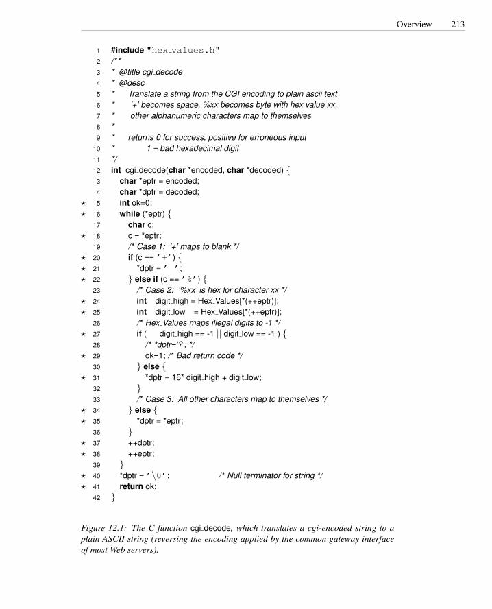
Overview 213
1 #include "hex values.h"2 /**3 * @title cgi decode4 * @desc5 * Translate a string from the CGI encoding to plain ascii text6 * ’+’ becomes space, %xx becomes byte with hex value xx,7 * other alphanumeric characters map to themselves8 *9 * returns 0 for success, positive for erroneous input
10 * 1 = bad hexadecimal digit11 */12 int cgi decode(char *encoded, char *decoded) {13 char *eptr = encoded;14 char *dptr = decoded;
? 15 int ok=0;? 16 while (*eptr) {
17 char c;? 18 c = *eptr;
19 /* Case 1: ’+’ maps to blank */? 20 if (c == ’+’) {? 21 *dptr = ’ ’;? 22 } else if (c == ’%’) {
23 /* Case 2: ’%xx’ is hex for character xx */? 24 int digit high = Hex Values[*(++eptr)];? 25 int digit low = Hex Values[*(++eptr)];
26 /* Hex Values maps illegal digits to -1 */? 27 if ( digit high == -1 || digit low == -1 ) {
28 /* *dptr=’?’; */? 29 ok=1; /* Bad return code */
30 } else {? 31 *dptr = 16* digit high + digit low;
32 }33 /* Case 3: All other characters map to themselves */
? 34 } else {? 35 *dptr = *eptr;
36 }? 37 ++dptr;? 38 ++eptr;
39 }? 40 *dptr = ’\0’; /* Null terminator for string */? 41 return ok;
42 }
Figure 12.1: The C function cgi decode, which translates a cgi-encoded string to aplain ASCII string (reversing the encoding applied by the common gateway interfaceof most Web servers).
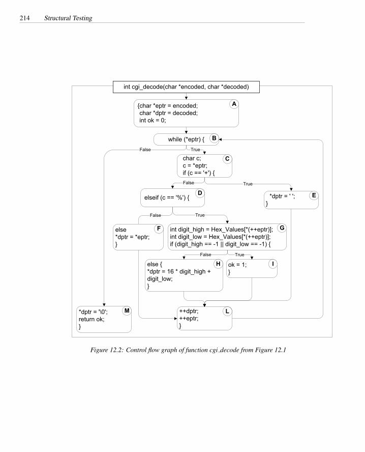
214 Structural Testing
{char *eptr = encoded;char *dptr = decoded;int ok = 0;
char c;c = *eptr;if (c == '+') {
*dptr = ' ';}
while (*eptr) {True
*dptr = '\0';return ok;}
False
True
int digit_high = Hex_Values[*(++eptr)];int digit_low = Hex_Values[*(++eptr)];if (digit_high == -1 || digit_low == -1) {
True
ok = 1;}
True
else {*dptr = 16 * digit_high + digit_low;}
False
++dptr;++eptr;}
False
False
elseif (c == '%') {
else*dptr = *eptr;}
int cgi_decode(char *encoded, char *decoded)
A
C
B
D E
F G
H I
LM
Figure 12.2: Control flow graph of function cgi decode from Figure 12.1

Statement Testing 215
T0 = { “ ”, “test”, “test+case%1Dadequacy” }T1 = { “adequate+test%0Dexecution%7U” }T2 = { “%3D”, “%A”, “a+b”, “test” }T3 = { “ ”, “+%0D+%4J” }T4 = { “first+test%9Ktest%K9” }
Table 12.1: Sample test suites for C function cgi decode from Figure 12.1
plementation of some items in the specification. For example, the program in Figure12.1 transforms all hexadecimal ASCII codes to the corresponding characters. Thus, itis not a correct implementation of a specification that requires control characters to beidentified and skipped. A test suite designed only to adequately cover the control struc-ture of the program will not explicitly include test cases to test for such faults, since noelements of the structure of the program correspond to this feature of the specification.
In practice, control flow testing criteria are used to evaluate the thoroughness of testsuites derived from functional testing criteria by identifying elements of the programsnot adequately exercised. Unexecuted elements may be due to natural differences be-tween specification and implementation, or they may reveal flaws of the software or itsdevelopment process: inadequacy of the specifications that do not include cases presentin the implementation; coding practice that radically diverges from the specification;or inadequate functional test suites.
Control flow adequacy can be easily measured with automatic tools. The degree ofcontrol flow coverage achieved during testing is often used as an indicator of progressand can be used as a criterion of completion of the testing activity.3
12.2 Statement Testing
The most intuitive control flow elements to be exercised are statements, that is, nodesof the control flow graph. The statement coverage criterion requires each statementto be executed at least once, reflecting the idea that a fault in a statement cannot berevealed without executing the faulty statement.
∆ statementadequacycriterion
Let T be a test suite for a program P. T satisfies the statement adequacy criterionfor P, iff, for each statement S of P, there exists at least one test case in T that causesthe execution of S.
This is equivalent to stating that every node in the control flow graph model ofprogram P is visited by some execution path exercised by a test case in T .
∆ statementcoverageThe statement coverage CStatement of T for P is the fraction of statements of program
P executed by at least one test case in T .
CStatement =number of executed statements
number of statements3Application of test adequacy criteria within the testing process is discussed in Chapter 20.

216 Structural Testing
T satisfies the statement adequacy criterion if CStatement = 1. The ratio of visitedcontrol flow graph nodes to total nodes may differ from the ratio of executed statementsto all statements, depending on the granularity of the control flow graph representation.Nodes in a control flow graph often represent basic blocks rather than individual state-∆ basic block
coverage ments, and so some standards (notably DOD-178B) refer to basic block coverage, thusindicating node coverage for a particular granularity of control flow graph. For thestandard control flow graph models discussed in Chapter 5, the relation between cov-erage of statements and coverage of nodes is monotonic: If the statement coverageachieved by test suite T1 is greater than the statement coverage achieved by test suiteT2, then the node coverage is also greater. In the limit, statement coverage is 1 exactlywhen node coverage is 1.
Let us consider, for example, the program of Figure 12.1. The program contains 18statements. A test suite T0
T0 = {“ ”, “test”, “test+case%1Dadequacy”}
does not satisfy the statement adequacy criterion because it does not execute statementok = 1 at line 29. The test suite T0 results in statement coverage of .94 (17/18), ornode coverage of .91 (10/11) relative to the control flow graph of Figure 12.2. On theother hand, a test suite with only test case
T1 = {“adequate+test%0Dexecution%7U”}
causes all statements to be executed and thus satisfies the statement adequacy criterion,reaching a coverage of 1.
Coverage is not monotone with respect to the size of test suites; test suites thatcontain fewer test cases may achieve a higher coverage than test suites that containmore test cases. T1 contains only one test case, while T0 contains three test cases, butT1 achieves a higher coverage than T0. (Test suites used in this chapter are summarizedin Table 12.1.)
Criteria can be satisfied by many test suites of different sizes. A test suite Both T1and Both T1 and
T2 = {“%3D”, “%A”, “a+b”, “test”}
cause all statements to be executed and thus satisfy the statement adequacy criterion forprogram cgi decode, although one consists of a single test case and the other consistsof four test cases.
Notice that while we typically wish to limit the size of test suites, in some cases wemay prefer a larger test suite over a smaller suite that achieves the same coverage. Atest suite with fewer test cases may be more difficult to generate or may be less helpfulin debugging. Let us suppose, for example, that we omitted the 1 in the statement atline 31 of the program in Figure 12.1. Both test suites T1 and T2 would reveal the fault,resulting in a failure, but T2 would provide better information for localizing the fault,since the program fails only for test case “%1D”, the only test case of T2 that exercisesthe statement at line 31.

Branch Testing 217
On the other hand, a test suite obtained by adding test cases to T2 would satisfy thestatement adequacy criterion, but would not have any particular advantage over T2 withrespect to the total effort required to reveal and localize faults. Designing complextest cases that exercise many different elements of a unit is seldom a good way tooptimize a test suite, although it may occasionally be justifiable when there is largeand unavoidable fixed cost (e.g., setting up equipment) for each test case regardless ofcomplexity.
Control flow coverage may be measured incrementally while executing a test suite.In this case, the contribution of a single test case to the overall coverage that has beenachieved depends on the order of execution of test cases. For example, in test suiteT2, execution of test case “%1D” exercises 16 of the 18 statements of the programcgi decode, but it exercises only 1 new statement if executed after “%A.” The incre-ment of coverage due to the execution of a specific test case does not measure theabsolute efficacy of the test case. Measures independent from the order of executionmay be obtained by identifying independent statements. However, in practice we areonly interested in the coverage of the whole test suite, and not in the contribution ofindividual test cases.
12.3 Branch Testing
A test suite can achieve complete statement coverage without executing all the possiblebranches in a program. Consider, for example, a faulty program cgi decode′ obtainedfrom program cgi decode by removing line 34. The control flow graph of programcgi decode′ is shown in Figure 12.3. In the new program there are no statements fol-lowing the false branch exiting node D. Thus, a test suite that tests only translationof specially treated characters but not treatment of strings containing other charactersthat are copied without change satisfies the statement adequacy criterion, but would notreveal the missing code in program cgi decode′. For example, a test suite T3
T3 = {“ ”, “+%0D+%4J”}
satisfies the statement adequacy criterion for program cgi decode′ but does not exercisethe false branch from node D in the control flow graph model of the program.
The branch adequacy criterion requires each branch of the program to be executedby at least one test case.
∆ branchadequacycriterion
Let T be a test suite for a program P. T satisfies the branch adequacy criterionfor P, iff, for each branch B of P, there exists at least one test case in T that causesexecution of B.
This is equivalent to stating that every edge in the control flow graph model ofprogram P belongs to some execution path exercised by a test case in T .
∆ branchcoverageThe branch coverage CBranch of T for P is the fraction of branches of program P
executed by at least one test case in T .
CBranch =number of executed branches
number of branches

218 Structural Testing
{char *eptr = encoded;char *dptr = decoded;int ok = 0;
char c;c = *eptr;if (c == '+') {
*dptr = ' ';}
while (*eptr) {
True
*dptr = '\0';return ok;}
False
True
int digit_high = Hex_Values[*(++eptr)];int digit_low = Hex_Values[*(++eptr)];if (digit_high == -1 || digit_low == -1) {
True
ok = 1;}
True
else {*dptr = 16 * digit_high + digit_low;}
False
++dptr;++eptr;}
False
False
elseif (c == '%') {
else {*dptr = *eptr;}
int cgi_decode(char *encoded, char *decoded)
A
C
B
D E
F G
H I
LM
Figure 12.3: The control flow graph of C function cgi decode′ which is obtained fromthe program of Figure 12.1 after removing node F.

Condition Testing 219
T satisfies the branch adequacy criterion if CBranch = 1.Test suite T3 achieves branch coverage of .88 since it executes 7 of the 8 branches of
program cgi decode′. Test suite T2 satisfies the branch adequacy criterion, and wouldreveal the fault. Intuitively, since traversing all edges of a graph causes all nodes tobe visited, test suites that satisfy the branch adequacy criterion for a program P alsosatisfy the statement adequacy criterion for the same program.4 The contrary is nottrue, as illustrated by test suite T3 for the program cgi decode′ presented earlier.
12.4 Condition Testing
Branch coverage is useful for exercising faults in the way a computation has been de-composed into cases. Condition coverage considers this decomposition in more detail,forcing exploration not only of both possible results of a Boolean expression control-ling a branch, but also of different combinations of the individual conditions in a com-pound Boolean expression.
Assume, for example, that we have forgotten the first operator ‘−’ in the conditionalstatement at line 27 resulting in the faulty expression
(digit high == 1 || digit low == -1).
As trivial as this fault seems, it can easily be overlooked if only the outcomes of com-plete Boolean expressions are explored. The branch adequacy criterion can be satis-fied, and both branches exercised, with test suites in which the first comparison eval-uates always to False and only the second is varied. Such tests do not systematicallyexercise the first comparison and will not reveal the fault in that comparison. Condi-tion adequacy criteria overcome this problem by requiring different basic conditions ofthe decisions to be separately exercised. The basic conditions, sometimes also calledelementary conditions, are comparisons, references to Boolean variables, and otherBoolean-valued expressions whose component subexpressions are not Boolean values.
The simplest condition adequacy criterion, called basic condition coverage requireseach basic condition to be covered. Each basic condition must have a True and a Falseoutcome at least once during the execution of the test suite.
∆ basic conditionadequacycriterion
A test suite T for a program P covers all basic conditions of P, that is, it satisfiesthe basic condition adequacy criterion, iff each basic condition in P has a true outcomein at least one test case in T and a false outcome in at least one test case in T .
∆ basic conditioncoverageThe basic condition coverage CBasic Condition of T for P is the fraction of the to-
tal number of truth values assumed by the basic conditions of program P during theexecution of all test cases in T .
CBasic Condition =total number of truth values assumed by all basic conditions
2 × number of basic conditions4We can consider entry and exit from the control flow graph as branches, so that branch adequacy will
imply statement adequacy even for units with no other control flow.

220 Structural Testing
T satisfies the basic condition adequacy criterion if CBasic Conditions = 1. Noticethat the total number of truth values that the basic conditions can take is twice thenumber of basic conditions, since each basic condition can assume value true or false.For example, the program in Figure 12.1 contains five basic conditions, which in summay take ten possible truth values. Three basic conditions correspond to the simpledecisions at lines 18, 22, and 24 — decisions that each contain only one basic condition.Thus they are covered by any test suite that covers all branches. The remaining twoconditions occur in the compound decision at line 27. In this case, test suites T1 andT3 cover the decisions without covering the basic conditions. Test suite T1 covers thedecision since it has an outcome True for the substring %0D and an outcome False forthe substring %7U of test case “adequate+test%0Dexecution%7U.” However test suiteT1 does not cover the first condition, since it has only outcome True . To satisfy thebasic condition adequacy criterion, we need to add an additional test case that producesoutcome false for the first condition (e.g., test case “basic%K7”).
The basic condition adequacy criterion can be satisfied without satisfying branchcoverage. For example, the test suite
T4 = {“first+test%9Ktest%K9”}
satisfies the basic condition adequacy criterion, but not the branch condition adequacycriterion, since the outcome of the decision at line 27 is always False . Thus branch andbasic condition adequacy criteria are not directly comparable.
An obvious extension that includes both the basic condition and the branch ade-quacy criteria is called branch and condition adequacy criterion, with the obvious def-inition: A test suite satisfies the branch and condition adequacy criterion if it satisfies∆ branch and
condition adequacy both the branch adequacy criterion and the condition adequacy criterion.A more complete extension that includes both the basic condition and the branch
adequacy criteria is the compound condition adequacy criterion,5 which requires a test∆ compoundcondition adequacy for each possible evaluation of compound conditions. It is most natural to visualize
compound condition adequacy as covering paths to leaves of the evaluation tree for theexpression. For example, the compound condition at line 27 would require coveringthe three paths in the following tree:
digit_high == -1
digit_low == 1
true false
FALSE
TRUE
true false
FALSE
Notice that due to the left-to-right evaluation order and short-circuit evaluation oflogical OR expressions in the C language, the value True for the first condition does
5Compound condition adequacy is also known as multiple condition coverage.

Condition Testing 221
not need to be combined with both values False and True for the second condition. Thenumber of test cases required for compound condition adequacy can, in principle, growexponentially with the number of basic conditions in a decision (all 2N combinationsof N basic conditions), which would make compound condition coverage impracticalfor programs with very complex conditions. Short-circuit evaluation is often effectivein reducing this to a more manageable number, but not in every case. The number oftest cases required to achieve compound condition coverage even for expressions builtfrom N basic conditions combined only with short-circuit Boolean operators like the&& and || of C and Java can still be exponential in the worst case.
Consider the number of cases required for compound condition coverage of thefollowing two Boolean expressions, each with five basic conditions. For the expressiona && b && c && d && e, compound condition coverage requires:
Test Case a b c d e(1) True True True True True(2) True True True True False(3) True True True False –(4) True True False – –(5) True False – – –(6) False – – – –
For the expression (((a || b) && c) || d) && e, however, compoundcondition adequacy requires many more combinations:
Test Case a b c d e(1) True – True – True(2) False True True – True(3) True – False True True(4) False True False True True(5) False False – True True(6) True – True – False(7) False True True – False(8) True – False True False(9) False True False True False
(10) False False – True False(11) True – False False –(12) False True False False –(13) False False – False –
An alternative approach that can be satisfied with the same number of test casesfor Boolean expressions of a given length regardless of short-circuit evaluation is themodified condition/decision coverage or MC/DC, also known as the modified condi-tion adequacy criterion. The modified condition/decision criterion requires that each ∆ modified condi-
tion/decisioncoverage(MC/DC)
basic condition be shown to independently affect the outcome of each decision. Thatis, for each basic condition C, there are two test cases in which the truth values of allevaluated conditions except C are the same, and the compound condition as a wholeevaluates to True for one of those test cases and False for the other. The modifiedcondition adequacy criterion can be satisfied with N +1 test cases, making it an attrac-

222 Structural Testing
tive compromise between number of required test cases and thoroughness of the test.It is required by important quality standards in aviation, including RTCA/DO-178B,“Software Considerations in Airborne Systems and Equipment Certification,” and itsEuropean equivalent EUROCAE ED-12B.
Recall the expression (((a || b) && c) || d) && e, which required 13different combinations of condition values for compound condition adequacy. Formodified condition/decision adequacy, only 6 combinations are required. Here theyhave been numbered for easy comparison with the previous table:
a b c d e Decision(1) True – True – True True(2) False True True – True True(3) True – False True True True(6) True – True – False False
(11) True – False False – False(13) False False – False – False
The values underlined in the table independently affect the outcome of the decision.Note that the same test case can cover the values of several basic conditions. Forexample, test case (1) covers value True for the basic conditions a, c and e. Note alsothat this is not the only possible set of test cases to satisfy the criterion; a differentselection of Boolean combinations could be equally effective.
12.5 Path Testing
Decision and condition adequacy criteria force consideration of individual program de-cisions. Sometimes, though, a fault is revealed only through exercise of some sequenceof decisions (i.e., a particular path through the program). It is simple (but impractical,as we will see) to define a coverage criterion based on complete paths rather than indi-vidual program decisions
∆ path adequacycriterion A test suite T for a program P satisfies the path adequacy criterion iff, for each path
p of P, there exists at least one test case in T that causes the execution of p.
This is equivalent to stating that every path in the control flow graph model ofprogram P is exercised by a test case in T .
∆ path coverageThe path coverage CPath of T for P is the fraction of paths of program P executed
by at least one test case in T .
CPath =number of executed paths
number of paths
Unfortunately, the number of paths in a program with loops is unbounded, so thiscriterion cannot be satisfied for any but the most trivial programs. For a program withloops, the denominator in the computation of the path coverage becomes infinite, andthus path coverage is zero no matter how many test cases are executed.
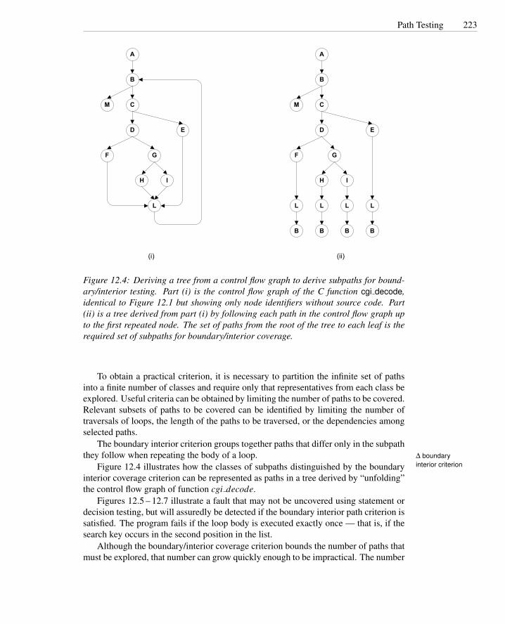
Path Testing 223
A
C
B
D E
F G
H I
L
M
LL
B B B
L
B
A
C
B
D E
F G
H I
L
M
(i) (ii)
Figure 12.4: Deriving a tree from a control flow graph to derive subpaths for bound-ary/interior testing. Part (i) is the control flow graph of the C function cgi decode,identical to Figure 12.1 but showing only node identifiers without source code. Part(ii) is a tree derived from part (i) by following each path in the control flow graph upto the first repeated node. The set of paths from the root of the tree to each leaf is therequired set of subpaths for boundary/interior coverage.
To obtain a practical criterion, it is necessary to partition the infinite set of pathsinto a finite number of classes and require only that representatives from each class beexplored. Useful criteria can be obtained by limiting the number of paths to be covered.Relevant subsets of paths to be covered can be identified by limiting the number oftraversals of loops, the length of the paths to be traversed, or the dependencies amongselected paths.
The boundary interior criterion groups together paths that differ only in the subpaththey follow when repeating the body of a loop. ∆ boundary
interior criterionFigure 12.4 illustrates how the classes of subpaths distinguished by the boundaryinterior coverage criterion can be represented as paths in a tree derived by “unfolding”the control flow graph of function cgi decode.
Figures 12.5 – 12.7 illustrate a fault that may not be uncovered using statement ordecision testing, but will assuredly be detected if the boundary interior path criterion issatisfied. The program fails if the loop body is executed exactly once — that is, if thesearch key occurs in the second position in the list.
Although the boundary/interior coverage criterion bounds the number of paths thatmust be explored, that number can grow quickly enough to be impractical. The number

224 Structural Testing
1 typedef struct cell {2 itemtype itemval;3 struct cell *link;4 } *list;5 #define NIL ((struct cell *) 0)6
7 itemtype search( list *l, keytype k)8 {9 struct cell *p = *l;
10 struct cell *back = NIL;11
12 /* Case 1: List is empty */13 if (p == NIL) {14 return NULLVALUE;15 }16
17 /* Case 2: Key is at front of list */18 if (k == p->itemval) {19 return p->itemval;20 }21
22 /* Default: Simple (but buggy) sequential search */23 p=p->link;24 while (1) {25 if (p == NIL) {26 return NULLVALUE;27 }28 if (k==p->itemval) { /* Move to front */29 back->link = p->link;30 p->link = *l;31 *l = p;32 return p->itemval;33 }34 back=p; p=p->link;35 }36 }
Figure 12.5: A C function for searching and dynamically rearranging a linked list,excerpted from a symbol table package. Initialization of the back pointer is missing,causing a failure only if the search key is found in the second position in the list.
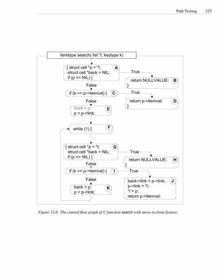
Path Testing 225
itemtype search( list *l, keytype k)
{ struct cell *p = *l; struct cell *back = NIL; if (p == NIL) {
ATrue
return NULLVALUE;}
B
if (k == p->itemval) { C
False
True
return p->itemval;}
D back = p; p = p->link;
E
False
while (1) { F
{ struct cell *p = *l; struct cell *back = NIL; if (p == NIL) {
GTrue
return NULLVALUE;}
H
if (k == p->itemval) { IFalse
True
back->link = p->link; p->link = *l; *l = p; return p->itemval;
J back = p; p = p->link;
K
False
Figure 12.6: The control flow graph of C function search with move-to-front feature.

226 Structural Testing
BC
E
F
H
A
I
JK
D
G
F
Figure 12.7: The boundary/interior subpaths for C function search.
of subpaths that must be covered can grow exponentially in the number of statementsand control flow graph nodes, even without any loops at all. Consider, for example, thefollowing pseudocode:
if (a) {S1;
}if (b) {
S2;}if (c) {
S3;}
...if (x) {
Sn;}
The subpaths through this control flow can include or exclude each of the state-ments Si, so that in total N branches result in 2N paths that must be traversed. Moreover,choosing input data to force execution of one particular path may be very difficult, oreven impossible if the conditions are not independent.6
Since coverage of non-looping paths is expensive, we can consider a variant of
6Section 12.8 discusses infeasible paths.

Path Testing 227
the boundary/interior criterion that treats loop boundaries similarly but is less stringentwith respect to other differences among paths.
∆ loop boundaryadequacycriterion
A test suite T for a program P satisfies the loop boundary adequacy criterion iff,for each loop l in P,
• In at least one execution, control reaches the loop, and then the loop controlcondition evaluates to False the first time it is evaluated.7
• In at least one execution, control reaches the loop, and then the body of the loopis executed exactly once before control leaves the loop.
• In at least one execution, the body of the loop is repeated more than once.
One can define several small variations on the loop boundary criterion. For ex-ample, we might excuse from consideration loops that are always executed a definitenumber of times (e.g., multiplication of fixed-size transformation matrices in a graphicsapplication). In practice we would like the last part of the criterion to be “many timesthrough the loop” or “as many times as possible,” but it is hard to make that precise(how many is “many?”).
It is easy enough to define such a coverage criterion for loops, but how can wejustify it? Why should we believe that these three cases — zero times through, oncethrough, and several times through — will be more effective in revealing faults than,say, requiring an even and an odd number of iterations? The intuition is that the loopboundary coverage criteria reflect a deeper structure in the design of a program. Thiscan be seen by their relation to the reasoning we would apply if we were trying toformally verify the correctness of the loop. The basis case of the proof would showthat the loop is executed zero times only when its postcondition (what should be trueimmediately following the loop) is already true. We would also show that an invariantcondition is established on entry to the loop, that each iteration of the loop maintainsthis invariant condition, and that the invariant together with the negation of the looptest (i.e., the condition on exit) implies the postcondition. The loop boundary criteriondoes not require us to explicitly state the precondition, invariant, and postcondition, butit forces us to exercise essentially the same cases that we would analyze in a proof.
There are additional path-oriented coverage criteria that do not explicitly considerloops. Among these are criteria that consider paths up to a fixed length. The mostcommon such criteria are based on Linear Code Sequence and Jump (LCSAJ). An ∆ linear code
sequence andjump (LCSAJ)
LCSAJ is defined as a body of code through which the flow of control may proceedsequentially, terminated by a jump in the control flow. Coverage of LCSAJ sequencesof length 1 is almost, but not quite, equivalent to branch coverage. Stronger criteria canbe defined by requiring N consecutive LCSAJs to be covered. The resulting criteriaare also referred to as T ERN+2, where N is the number of consecutive LCSAJs to becovered. Conventionally, T ER1 and T ER2 refer to statement and branch coverage,respectively.
The number of paths to be exercised can also be limited by identifying a subsetthat can be combined (in a manner to be described shortly) to form all the others.
7For a while or for loop, this is equivalent to saying that the loop body is executed zero times.

228 Structural Testing
Such a set of paths is called a basis set, and from graph theory we know that everyconnected graph with n nodes, e edges, and c connected components has a basis set ofonly e−n+ c independent subpaths. Producing a single connected component from aprogram flow graph by adding a “virtual edge” from the exit to the entry, the formulabecomes e−n+2, which is called the cyclomatic complexity of the control flow graph.Cyclomatic testing consists of attempting to exercise any set of execution paths that isa basis set for the control flow graph.∆ cyclomatic testing
To be more precise, the sense in which a basis set of paths can be combined to formother paths is to consider each path as a vector of counts indicating how many timeseach edge in the control flow graph was traversed. For example, the third element ofthe vector might be the number of times a particular branch is taken. The basis setis combined by adding or subtracting these vectors (and not, as one might intuitivelyexpect, by concatenating paths). Consider again the pseudocode
if (a) {S1;
}if (b) {
S2;}if (c) {
S3;}
...if (x) {
Sn;}
While the number of distinct paths through this code is exponential in the numberof if statements, the number of basis paths is small: only n + 1 if there are n if state-ments. We can represent one basis set (of many possible) for a sequence of four such ifstatements by indicating whether each predicate evaluates to True or False:
1 False False False False2 True False False False3 False True False False4 False False True False5 False False False True
The path represented as 〈True,False,True,False〉 is formed from these by addingpaths 2 and 4 and then subtracting path 1.
Cyclomatic testing does not require that any particular basis set is covered. Rather,it counts the number of independent paths that have actually been covered (i.e., count-ing a new execution path as progress toward the coverage goal only if it is independentof all the paths previously exercised), and the coverage criterion is satisfied when thiscount reaches the cyclomatic complexity of the code under test.

Procedure Call Testing 229
12.6 Procedure Call Testing
The criteria considered to this point measure coverage of control flow within individualprocedures. They are not well suited to integration testing or system testing. It isdifficult to steer fine-grained control flow decisions of a unit when it is one small partof a larger system, and the cost of achieving fine-grained coverage for a system ormajor component is seldom justifiable. Usually it is more appropriate to choose acoverage granularity commensurate with the granularity of testing. Moreover, if unittesting has been effective, then faults that remain to be found in integration testing willbe primarily interface faults, and testing effort should focus on interfaces between unitsrather than their internal details.
In some programming languages (FORTRAN, for example), a single proceduremay have multiple entry points, and one would want to test invocation through each ofthe entry points. More common are procedures with multiple exit points. For example,the code of Figure 12.5 has four different return statements. One might want to check ∆ procedure
entry and exittesting
that each of the four returns is exercised in the actual context in which the procedure isused. Each of these would have been exercised already if even the simplest statementcoverage criterion were satisfied during unit testing, but perhaps only in the context ofa simple test driver; testing in the real context could reveal interface faults that werepreviously undetected.
Exercising all the entry points of a procedure is not the same as exercising all thecalls. For example, procedure A may call procedure C from two distinct points, andprocedure B may also call procedure C. In this case, coverage of calls of C meansexercising calls at all three points. If the component under test has been constructed ∆ call coverage
in a bottom-up manner, as is common, then unit testing of A and B may already haveexercised calls of C. In that case, even statement coverage of A and B would ensurecoverage of the calls relation (although not in the context of the entire component).
The search function in Figure 12.5 was originally part of a symbol table package ina small compiler. It was called at only one point, from one other C function in the sameunit.8 That C function, in turn, was called from tens of different points in a scanner anda parser. Coverage of calls requires exercising each statement in which the parser andscanner access the symbol table, but this would almost certainly be satisfied by a set oftest cases exercising each production in the grammar accepted by the parser.
When procedures maintain internal state (local variables that persist from call tocall), or when they modify global state, then properties of interfaces may only be re-vealed by sequences of several calls. In object-oriented programming, local state ismanipulated by procedures called methods, and systematic testing necessarily concernssequences of method calls on the same object. Even simple coverage of the “calls” re-lation becomes more challenging in this environment, since a single call point may bedynamically bound to more than one possible procedure (method). While these com-plications may arise even in conventional procedural programs (e.g., using functionpointers in C), they are most prevalent in object-oriented programming. Not surpris-ingly, then, approaches to systematically exercising sequences of procedure calls are
8The “unit” in this case is the C source file, which provided a single data abstraction through severalrelated C functions, much as a C++ or Java class would provide a single abstraction through several methods.The search function was analogous in this case to a private (internal) method of a class.

230 Structural Testing
beginning to emerge mainly in the field of object-oriented testing, and we thereforecover them in Chapter 15.
12.7 Comparing Structural Testing Criteria
The power and cost of the structural test adequacy criteria described in this chaptercan be formally compared using the subsumes relation introduced in Chapter 9. Therelations among these criteria are illustrated in Figure 12.8. They are divided into twobroad categories: practical criteria that can always be satisfied by test sets whose sizeis at most a linear function of program size; and criteria that are of mainly theoreticalinterest because they may require impractically large numbers of test cases or even (inthe case of path coverage) an infinite number of test cases.
The hierarchy can be roughly divided into a part that relates requirements for cov-ering program paths and another part that relates requirements for covering combina-tions of conditions in branch decisions. The two parts come together at branch cov-erage. Above branch coverage, path-oriented criteria and condition-oriented criteriaare generally separate, because there is considerable cost and little apparent benefit incombining them. Statement coverage is at the bottom of the subsumes hierarchy forsystematic coverage of control flow. Applying any of the structural coverage criteria,therefore, implies at least executing all the program statements.
Procedure call coverage criteria are not included in the figure, since they do notconcern internal control flow of procedures and are thus incomparable with the controlflow coverage criteria.
12.8 The Infeasibility Problem
Sometimes no set of test cases is capable of satisfying some test coverage criterion fora particular program, because the criterion requires execution of a program elementthat can never be executed. This is true even for the statement coverage criterion, weakas it is. Unreachable statements can occur as a result of defensive programming (e.g.,checking for error conditions that never occur) and code reuse (reusing code that ismore general than strictly required for the application). Large amounts of “fossil” codemay accumulate when a legacy application becomes unmanageable. In that case, theymay indicate serious maintainability problems, but some unreachable code is commoneven in well-designed, well-maintained systems, and must be accommodated in testingprocesses that otherwise require satisfaction of coverage criteria.
Stronger coverage criteria tend to call for coverage of more elements that may beinfeasible. For example, in discussing multiple condition coverage, we implicitly as-sumed that basic conditions were independent and could therefore occur in any combi-nation. In reality, basic conditions may be comparisons or other relational expressionsand may be interdependent in ways that make certain combinations infeasible. Forexample, in the expression (a > 0 && a < 10), it is not possible for both basic condi-tions to be False . Fortunately, short-circuit evaluation rules ensure that the combination

The Infeasibility Problem 231
Path Testing
Boundary interior testing Compound condition testing
Cyclomatic testing
LCSAJ testing
MC/DC testing
Branch and condition testing
Basic condition testing
Branch testing
Statement testingLoop boundary testing
THEO
RETI
CAL
CRIT
ERIA
PRAC
TICA
L CR
ITER
IA
Figure 12.8: The subsumption relation among structural test adequacy criteria de-scribed in this chapter.

232 Structural Testing
〈False,False〉 is not required for multiple condition coverage of this particular expres-sion in a C or Java program.
The infeasibility problem is most acute for path-based structural coverage criteria,such as the boundary/interior coverage criterion. Consider, for example, the followingsimple code sequence:
if (a < 0) {a = 0;
}if (a > 10) {
a = 10;}
It is not possible to traverse the subpath on which the True branch is taken for both ifstatements. In the trivial case where these if statements occur together, the problem isboth easy to understand and to avoid (by placing the second if within an else clause),but essentially the same interdependence can occur when the decisions are separatedby other code.
An easy but rather unsatisfactory solution to the infeasibility problem is to makeallowances for it by setting a coverage goal less than 100%. For example, we couldrequire 90% coverage of basic blocks, on the grounds that no more than 10% of theblocks in a program should be infeasible. A 10% allowance for infeasible blocks maybe insufficient for some units and too generous for others.
The other main option is requiring justification of each element left uncovered.This is the approach taken in some quality standards, notably RTCA/DO-178B andEUROCAE ED-12B for modified condition/decision coverage (MC/DC). Explainingwhy each element is uncovered has the salutary effect of distinguishing between defen-sive coding and sloppy coding or maintenance, and may also motivate simpler codingstyles. However, it is more expensive (because it requires manual inspection and under-standing of each element left uncovered) and is unlikely to be cost-effective for criteriathat impose test obligations for large numbers of infeasible paths. This problem, evenmore than the large number of test cases that may be required, leads us to conclude thatstringent path-oriented coverage criteria are seldom cost-effective.
Open Research Issues
Devising and comparing structural criteria was a hot topic in the 1980s. It is no longeran active research area for imperative programming, but new programming paradigmsor design techniques present new challenges. Polymorphism, dynamic binding, andobject-oriented and distributed code open new problems and require new techniques, asdiscussed in other chapters. Applicability of structural criteria to architectural designdescriptions is still under investigation. Usefulness of structural criteria for implicitcontrol flow has been addressed only recently.
Early testing research, including research on structural coverage criteria, was con-cerned largely with improving the fault-detection effectiveness of testing. Today, themost pressing issues are cost and schedule. Better automated techniques for identifyinginfeasible paths will be necessary before more stringent structural coverage criteria can

The Infeasibility Problem 233
be seriously considered in any but the most critical of domains. Alternatively, for manyapplications it may be more appropriate to gather evidence of feasibility from actualproduct use; this is called residual test coverage monitoring and is a topic of currentresearch.
Further Reading
The main structural adequacy criteria are presented in Myers’ The Art of Software Test-ing [Mye79], which has been a preeminent source of information for more than twodecades. It is a classic despite its age, which is evident from the limited set of tech-niques addressed and the programming language used in the examples. The excellentsurvey by Adrion et al. [ABC82] remains the best overall survey of testing techniques,despite similar age. Frankl and Weyuker [FW93] provide a modern treatment of thesubsumption hierarchy among structural coverage criteria.
Boundary/interior testing is presented by Howden [How75]. Woodward et al. [WHH80]present LCSAJ testing. Cyclomatic testing is described by McCabe [McC83]. Residualtest coverage measurement is described by Pavlopoulou and Young [PY99].
Related Topics
Readers with a strong interest in coverage criteria should continue with the next chap-ter, which presents data flow testing criteria. Others may wish to proceed to Chapter 15,which addresses testing object-oriented programs. Readers wishing a more compre-hensive view of unit testing may continue with Chapters 17 on test scaffolding and testdata generation. Tool support for structural testing is discussed in Chapter 23.
Exercises
12.1. Let us consider the following loop, which appears in C lexical analyzers gener-ated by the tool flex:9
1 for ( n = 0;2 n < max size && (c = getc( yyin )) != EOF && c != ’\n’;3 ++n )4 buf[n] = (char) c;
Devise a set of test cases that satisfy the compound condition adequacy criterionand a set of test cases that satisfy the modified condition adequacy criterion withrespect to this loop.
9Flex is a widely used generator of lexical analyzers. Flex was written by Vern Paxson and is compatiblewith the original AT&T lex written by M.E. Lesk. This excerpt is from version 2.5.4 of flex, distributed withthe Linux operating system.

234 Structural Testing
12.2. The following if statement appears in the Java source code of Grappa,10 a graphlayout engine distributed by AT&T Laboratories:
1 if(pos < parseArray.length2 && (parseArray[pos] == ’{’3 || parseArray[pos] == ’}’4 || parseArray[pos] == ’|’)) {5 continue;6 }
(a) Derive a set of test case specifications and show that it satisfies the MC/DCcriterion for this statement. For brevity, abbreviate each of the basic condi-tions as follows:
Room for pos < parseArray.length
Open for parseArray[pos] == ’{’Close for parseArray[pos] == ’}’Bar for parseArray[pos] == ’|’
(b) Do the requirements for compound condition coverage and modified condi-tion/decision coverage differ in this case? Aside from increasing the num-ber of test cases, what difference would it make if we attempted to exhaus-tively cover all combinations of truth values for the basic conditions?
12.3. Prove that the number of test cases required to satisfy the modified conditionadequacy criterion for a predicate with N basic conditions is N +1.
12.4. The number of basis paths (cyclomatic complexity) does not depend on whethernodes of the control flow graph are individual statements or basic blocks thatmay contain several statements. Why?
12.5. Derive the subsumption hierarchy for the call graph coverage criteria describedin this chapter, and justify each of the relationships.
12.6. If the modified condition/decision adequacy criterion requires a test case that isnot feasible because of interdependent basic conditions, should this always betaken as an indication of a defect in design or coding? Why or why not?
10The statement appears in file Table.java. This source code is copyright 1996, 1997, 1998 by AT&TCorporation. Grappa is distributed as open source software, available at the time of this writing from http://www.graphviz.org. Formatting of the line has been altered for readability in this printed form.

Chapter 13
Data Flow Testing
Exercising every statement or branch with test cases is a practical goal, but exercisingevery path is impossible. Even the number of simple (that is, loop-free) paths can beexponential in the size of the program. Path-oriented selection and adequacy criteriamust therefore select a tiny fraction of control flow paths. Some control flow adequacycriteria, notably the loop boundary interior condition, do so heuristically. Data flowtest adequacy criteria improve over pure control flow criteria by selecting paths basedon how one syntactic element can affect the computation of another.
Required Background
• Chapter 6
At least the basic data flow models presented in Chapter 6, Section 6.1, are re-quired to understand this chapter, although algorithmic details of data flow anal-ysis can be deferred. Section 6.5 of that chapter is important background forSection 13.4 of the current chapter. The remainder of Chapter 6 is useful back-ground but not strictly necessary to understand and apply data flow testing.
• Chapter 9
The introduction to test case adequacy and test case selection in general sets thecontext for this chapter. It is not strictly required for understanding this chapter,but is helpful for understanding how the techniques described in this chaptershould be applied.
• Chapter 12
The data flow adequacy criteria presented in this chapter complement controlflow adequacy criteria. Knowledge about control flow adequacy criteria is desir-able but not strictly required for understanding this chapter.
235

236 Data Flow Testing
13.1 Overview
We have seen in Chapter 12 that structural testing criteria are practical for single ele-ments of the program, from simple statements to complex combinations of conditions,but become impractical when extended to paths. Even the simplest path testing criteriarequire covering large numbers of paths that tend to quickly grow far beyond test suitesof acceptable size for nontrivial programs.
Close examination of paths that need to be traversed to satisfy a path selectioncriterion often reveals that, among a large set of paths, only a few are likely to uncoverfaults that could have escaped discovery using condition testing coverage. Criteria thatselect paths based on control structure alone (e.g., boundary interior testing) may not beeffective in identifying these few significant paths because their significance dependsnot only on control flow but on data interactions.
Data flow testing is based on the observation that computing the wrong value leadsto a failure only when that value is subsequently used. Focus is therefore moved fromcontrol flow to data flow. Data flow testing criteria pair variable definitions with uses,ensuring that each computed value is actually used, and thus selecting from amongmany execution paths a set that is more likely to propagate the result of erroneouscomputation to the point of an observable failure.
Consider, for example, the C function cgi decode of Figure 13.1, which decodes astring that has been transmitted through the Web’s Common Gateway Interface. Dataflow testing criteria would require one to execute paths that first define (change thevalue of) variable eptr (e.g., by incrementing it at line 37) and then use the new valueof variable eptr (e.g., using variable eptr to update the array indexed by dptr at line 34).Since a value defined in one iteration of the loop is used on a subsequent iteration, weare obliged to execute more than one iteration of the loop to observe the propagationof information from one iteration to the next.
13.2 Definition-Use Associations
Data flow testing criteria are based on data flow information — variable definitions anduses. Table 13.1 shows definitions and uses for the program cgi decode of Figure 13.1.Recall that when a variable occurs on both sides of an assignment, it is first used andthen defined, since the value of the variable before the assignment is used for comput-ing the value of the variable after the assignment. For example, the ++eptr incrementoperation in C is equivalent to the assignment eptr = eptr + 1, and thus first uses andthen defines variable eptr.
We will initially consider treatment of arrays and pointers in the current examplein a somewhat ad hoc fashion and defer discussion of the general problem to Sec-tion 13.4. Variables eptr and dptr are used for indexing the input and output strings.In program cgi decode, we consider the variables as both indexes (eptr and dptr) andstrings (*eptr and *dptr). The assignment *dptr = *eptr is treated as a definition of thestring *dptr as well as a use of the index dptr, the index eptr, and the string *eptr, sincethe result depends on both indexes as well as the contents of the source string. Achange to an index is treated as a definition of both the index and the string, since a

Definition-Use Associations 237
1
2 /* External file hex values.h defines Hex Values[128]3 * with value 0 to 15 for the legal hex digits (case-insensitive)4 * and value -1 for each illegal digit including special characters5 */6
7 #include "hex values.h"
8 /** Translate a string from the CGI encoding to plain ascii text.9 * ’+’ becomes space, %xx becomes byte with hex value xx,
10 * other alphanumeric characters map to themselves.11 * Returns 0 for success, positive for erroneous input12 * 1 = bad hexadecimal digit13 */14 int cgi decode(char *encoded, char *decoded) {15 char *eptr = encoded;16 char *dptr = decoded;17 int ok=0;18 while (*eptr) {19 char c;20 c = *eptr;21
22 if (c == ’+’) { /* Case 1: ’+’ maps to blank */23 *dptr = ’ ’;24 } else if (c == ’%’) { /* Case 2: ’%xx’ is hex for character xx */25 int digit high = Hex Values[*(++eptr)];26 int digit low = Hex Values[*(++eptr)];27 if ( digit high == -1 || digit low == -1 ) {28 /* *dptr=’?’; */29 ok=1; /* Bad return code */30 } else {31 *dptr = 16* digit high + digit low;32 }33 } else { /* Case 3: All other characters map to themselves */34 *dptr = *eptr;35 }36 ++dptr;37 ++eptr;38 }39 *dptr = ’\0’; /* Null terminator for string */40 return ok;41 }
Figure 13.1: The C function cgi decode, which translates a cgi-encoded string to aplain ASCII string (reversing the encoding applied by the common gateway interfaceof most Web servers). This program is also used in Chapter 12 and also presented inFigure 12.1 of Chapter 12.

238 Data Flow Testing
Variable Definitions Usesencoded 14 15decoded 14 16*eptr 15, 25, 26, 37 18, 20, 25, 26, 34eptr 15, 25, 26, 37 15, 18, 20, 25, 26, 34, 37*dptr 16, 23, 31, 34, 36, 39 40dptr 16 36 16, 23, 31, 34, 36, 39ok 17, 29 40c 20 22, 24digit high 25 27, 31digit low 26 27, 31Hex Values – 25, 26
Table 13.1: Definitions and uses for C function cgi decode. *eptr and *dptr indicate thestrings, while eptr and dptr indicate the indexes.
change of the index changes the value accessed by it. For example, in the statement atline 36 (++dptr), we have a use of variable dptr followed by a definition of variables dptrand *dptr.
It is somewhat counterintuitive that we have definitions of the string *eptr, sinceit is easy to see that the program is scanning the encoded string without changingit. For the purposes of data flow testing, though, we are interested in interactionsbetween computation at different points in the program. Incrementing the index eptr isa “definition” of *eptr in the sense that it can affect the value that is next observed by ause of *eptr.
Pairing definitions and uses of the same variable v identifies potential data inter-actions through v — definition-use pairs (DU pairs). Table 13.2 shows the DU pairs∆ DU pair
in program cgi decode of Figure 13.1. Some pairs of definitions and uses from Ta-ble 13.1 do not occur in Table 13.2, since there is no definition-clear path betweenthe two statements. For example, the use of variable eptr at line 15 cannot be reachedfrom the increment at line 37, so there is no DU pair 〈37,15〉. The definitions of vari-ables *eptr and eptr at line 25, are paired only with the respective uses at line 26, sincesuccessive definitions of the two variables at line 26 kill the definition at line 25 andeliminate definition-clear paths to any other use.
A DU pair requires the existence of at least one definition-clear path from definitionto use, but there may be several. Additional uses on a path do not interfere with thepair. We sometimes use the term DU path to indicate a particular definition-clear path∆ DU path
between a definition and a use. For example, let us consider the definition of *eptr atline 37 and the use at line 34. There are infinitely many paths that go from line 37 tothe use at line 34. There is one DU path that does not traverse the loop while goingfrom 37 to 34. There are infinitely many paths from 37 back to 37, but only two DUpaths, because the definition at 37 kills the previous definition at the same point.
Data flow testing, like other structural criteria, is based on information obtainedthrough static analysis of the program. We discard definitions and uses that cannotbe statically paired, but we may select pairs even if none of the statically identifiable

Data Flow Testing Criteria 239
Variable DU Pairs*eptr 〈 15, 18 〉, 〈 15, 20 〉, 〈 15, 25 〉, 〈 15, 34 〉 〈 25, 26 〉, 〈 26, 37 〉
〈 37, 18 〉, 〈 37, 20 〉, 〈 37, 25 〉, 〈 37, 34 〉eptr 〈 15, 15 〉, 〈 15, 18 〉, 〈 15, 20 〉, 〈 15, 25 〉, 〈 15, 34 〉, 〈 15, 37 〉,
〈 25, 26 〉, 〈 26, 37 〉 〈 37, 18 〉, 〈 37, 20 〉, 〈 37, 25 〉, 〈 37, 34 〉, 〈 37, 37 〉*dptr 〈 39, 40 〉dptr 〈 16, 16 〉, 〈 16, 23 〉, 〈 16, 31 〉, 〈 16, 34 〉, 〈 16, 36 〉, 〈 16, 39 〉,
〈 36, 23 〉, 〈 36, 31 〉, 〈 36, 34 〉, 〈 36, 36 〉, 〈 36, 39 〉ok 〈 17, 40 〉, 〈 29, 40 〉c 〈 20, 22 〉, 〈 20 24 〉digit high 〈 25, 27 〉, 〈 25, 31 〉digit low 〈 26, 27 〉, 〈 26, 31 〉encoded 〈 14, 15〉decoded 〈 14, 16〉
Table 13.2: DU pairs for C function cgi decode. Variable Hex Values does not appearbecause it is not defined (modified) within the procedure.
definition-clear paths is actually executable. In the current example, we have madeuse of information that would require a quite sophisticated static data flow analyzer, asdiscussed in Section 13.4.
13.3 Data Flow Testing Criteria
Various data flow testing criteria can be defined by requiring coverage of DU pairs invarious ways.
The All DU pairs adequacy criterion requires each DU pair to be exercised in atleast one program execution, following the idea that an erroneous value produced byone statement (the definition) might be revealed only by its use in another statement.
∆ all DU pairsadequacycriterion
A test suite T for a program P satisfies the all DU pairs adequacy criterion iff, foreach DU pair du of P, at least one test case in T exercises du.
The corresponding coverage measure is the proportion of covered DU pairs:∆ all DU pairscoverageThe all DU pairs coverage CDU pairs of T for P is the fraction of DU pairs of program
P exercised by at least one test case in T .
CDU pairs =number of exercised DU pairs
number of DU pairs
The all DU pairs adequacy criterion assures a finer grain coverage than statementand branch adequacy criteria. If we consider, for example, function cgi decode, we caneasily see that statement and branch coverage can be obtained by traversing the whileloop no more than once, for example, with the test suite Tbranch = {“+”, “%3D”, “%FG”, “t”}while several DU pairs cannot be covered without executing the while loop at least

240 Data Flow Testing
twice. The pairs that may remain uncovered after statement and branch coverage cor-respond to occurrences of different characters within the source string, and not only atthe beginning of the string. For example, the DU pair 〈37, 25〉 for variable *eptr can becovered with a test case TCDU pairs“test%3D” where the hexadecimal escape sequenceoccurs inside the input string, but not with “%3D.” The test suite TDU pairs obtained byadding the test case TCDU pairs to the test suite Tbranch satisfies the all DU pairs ade-quacy criterion, since it adds both the cases of a hexadecimal escape sequence and anASCII character occurring inside the input string.
One DU pair might belong to many different execution paths. The All DU pathsadequacy criterion extends the all DU pairs criterion by requiring each simple (nonlooping) DU path to be traversed at least once, thus including the different ways ofpairing definitions and uses. This can reveal a fault by exercising a path on which adefinition of a variable should have appeared but was omitted.
∆ all DU pathsadequacy criterion A test suite T for a program P satisfies the all DU paths adequacy criterion iff, for
each simple DU path dp of P, there exists at least one test case in T that exercises apath that includes dp.
The corresponding coverage measure is the fraction of covered simple DU paths:∆ all DU pathscoverage The all DU pair coverage CDU paths of T for P is the fraction of simple DU paths of
program P executed by at least one test case in T .
CDU paths =number of exercised simple DU paths
number of simple DU paths
The test suite TDU pairs does not satisfy the all DU paths adequacy criterion, sinceboth DU pairs 〈37,37〉 for variable eptr and 〈36,23〉 for variable dptr correspond eachto two simple DU paths, and in both cases one of the two paths is not covered by testcases in TDU pairs. The uncovered paths correspond to a test case that includes character’+’ occurring within the input string (e.g., test case TCDU paths = “test+case”).
Although the number of simple DU paths is often quite reasonable, in the worstcase it can be exponential in the size of the program unit. This can occur when the codebetween the definition and use of a particular variable is essentially irrelevant to thatvariable, but contains many control paths, as illustrated by the example in Figure 13.2:The code between the definition of ch in line 2 and its use in line 12 does not modifych, but the all DU paths coverage criterion would require that each of the 256 paths beexercised.
We normally consider both All DU paths and All DU pairs adequacy criteria asrelatively powerful and yet practical test adequacy criteria, as depicted in Figure 12.8on page 231. However, in some cases, even the all DU pairs criterion may be too costly.In these cases, we can refer to a coarser grain data flow criterion, the All definitionsadequacy criterion, which requires pairing each definition with at least one use.
∆ all definitionsadequacy criterion A test suite T for a program P satisfies the all definitions adequacy criterion for P
iff, for each definition def of P, there exists at least one test case in T that exercises aDU pair that includes def.

Data Flow Coverage with Complex Structures 241
1
2 void countBits(char ch) {3 int count = 0;4 if (ch & 1) ++count;5 if (ch & 2) ++count;6 if (ch & 4) ++count;7 if (ch & 8) ++count;8 if (ch & 16) ++count;9 if (ch & 32) ++count;
10 if (ch & 64) ++count;11 if (ch & 128) ++count;12 printf("’%c’ (0X%02x) has %d bits set to 1\n",13 ch, ch, count);14 }
Figure 13.2: A C procedure with a large number of DU paths. The number of DUpaths for variable ch is exponential in the number of if statements, because the use ineach increment and in the final print statement can be paired with any of the precedingdefinitions. The number of DU paths for variable count is the same as the number ofDU pairs. For variable ch, there is only one DU pair, matching the procedure headerwith the final print statement, but there are 256 definition-clear paths between thosestatements — exponential in the number of intervening if statements.
The corresponding coverage measure is the proportion of covered definitions, wherewe say a definition is covered only if the value is used before being killed:
∆ all definitionscoverageThe all definitions coverage CDe f of T for P is the fraction of definitions of program
P covered by at least one test case in T .
Cde f s =number of covered definitions
number of definitions
13.4 Data Flow Coverage with Complex Structures
Like all static analysis techniques, data flow analysis approximates the effects of pro-gram executions. It suffers imprecision in modeling dynamic constructs, in particulardynamic access to storage, such as indexed access to array elements or pointer accessto dynamically allocated storage. We have seen in Chapter 6 (page 94) that the propertreatment of potential aliases involving indexes and pointers depends on the use towhich analysis results will be put. For the purpose of choosing test cases, some risk ofunderestimating alias sets may be preferable to gross overestimation or very expensiveanalysis.
The precision of data flow analysis depends on the precision of alias informationused in the analysis. Alias analysis requires a trade-off between precision and compu-

242 Data Flow Testing
1 void pointer abuse() {2 int i=5, j=10, k=20;3 int *p, *q;4 p = &j + 1;5 q = &k;6 *p = 30;7 *q = *q + 55;8 printf("p=%d, q=%d\n", *p, *q);9 }
Figure 13.3: Pointers to objects in the program stack can create essentially arbitrarydefinition-use associations, particularly when combined with pointer arithmetic as inthis example.
tational expense, with significant overestimation of alias sets for approaches that can bepractically applied to real programs. In the case of data flow testing, imprecision canbe mitigated by specializing the alias analysis to identification of definition-clear pathsbetween a potentially matched definition and use. We do not need to compute aliasesfor all possible behaviors, but only along particular control flow paths. The risk of un-derestimating alias sets in a local analysis is acceptable considering the application inchoosing good test cases rather than offering hard guarantees of a property.
In the cgi decode example we have made use of information that would requireeither extra guidance from the test designer or a sophisticated tool for data flow andalias analysis. We may know, from a global analysis, that the parameters encoded anddecoded never refer to the same or overlapping memory regions, and we may infer thatinitially eptr and dptr likewise refer to disjoint regions of memory, over the whole rangeof values that the two pointers take. Lacking this information, a simple static data flowanalysis might consider *dptr a potential alias of *eptr and might therefore consider theassignment *dptr = *eptr a potential definition of both *dptr and *eptr. These spuriousdefinitions would give rise to infeasible DU pairs, which produce test obligations thatcan never be satisfied. A local analysis that instead assumes (without verification) that*eptr and *dptr are distinct could fail to require an important test case if they can bealiases. Such underestimation may be preferable to creating too many infeasible testobligations.
A good alias analysis can greatly improve the applicability of data flow testing butcannot eliminate all problems. Undisciplined use of dynamic access to storage canmake precise alias analysis extremely hard or impossible. For example, the use ofpointer arithmetic in the program fragment of Figure 13.3 results in aliases that dependon the way the compiler arranges variables in memory.

The Infeasibility Problem 243
13.5 The Infeasibility Problem
Not all elements of a program are executable, as discussed in Section 12.8 of Chap-ter 12. The path-oriented nature of data flow testing criteria aggravates the problemsince infeasibility creates test obligations not only for isolated unexecutable elements,but also for infeasible combinations of feasible elements.
Complex data structures may amplify the infeasibility problem by adding infeasiblepaths as a result of alias computation. For example, while we can determine that x[i]is an alias of x[j] exactly when i = j, we may not be able to determine whether i can beequal to j in any possible program execution.
Fortunately, the problem of infeasible paths is usually modest for the all definitionsand all DU pairs adequacy criteria, and one can typically achieve levels of coveragecomparable to those achievable with simpler criteria like statement and branch ade-quacy during unit testing. The all DU paths adequacy criterion, on the other hand,often requires much larger numbers of control flow paths. It presents a greater prob-lem in distinguishing feasible from infeasible paths and should therefore be used withdiscretion.
Open Research Issues
Data flow test adequacy criteria are close to the border between techniques that can beapplied at low cost with simple tools and techniques that offer more power but at muchhigher cost. While in principle data flow test coverage can be applied at modest cost (atleast up to the all DU adequacy criterion), it demands more sophisticated tool supportthan test coverage monitoring tools based on control flow alone.
Fortunately, data flow analysis and alias analysis have other important applications.Improved support for data flow testing may come at least partly as a side benefit of re-search in the programming languages and compilers community. In particular, findinga good balance of cost and precision in data flow and alias analysis across procedureboundaries (interprocedural or “whole program” analysis) is an active area of research.
The problems presented by pointers and complex data structures cannot be ignored.In particular, modern object-oriented languages like Java use reference semantics —an object reference is essentially a pointer — and so alias analysis (preferably inter-procedural) is a prerequisite for applying data flow analysis to object-oriented pro-grams.
Further Reading
The concept of test case selection using data flow information was apparently first sug-gested in 1976 by Herman [Her76], but that original paper is not widely accessible. Themore widely known version of data flow test adequacy criteria was developed indepen-dently by Rapps and Weyuker [RW85] and by Laski and Korel [LK83]. The variety ofdata flow testing criteria is much broader than the handful of criteria described in thischapter; Clarke et al. present a formal comparison of several criteria [CPRZ89]. Frankl

244 Data Flow Testing
and Weyuker consider the problem of infeasible paths and how they affect the relativepower of data flow and other structural test adequacy criteria [FW93].
Marx and Frankl consider the problem of aliases and application of alias analysison individual program paths [MF96]. A good example of modern empirical research oncosts and effectiveness of structural test adequacy criteria, and data flow test coveragein particular, is Frankl and Iakounenko [FI98].
Related Topics
The next chapter discusses model-based testing. Section 14.4 shows how control anddata flow models can be used to derive test cases from specifications. Chapter 15 illus-trates the use of data flow analysis for structural testing of object oriented programs.
Readers interested in the use of data flow for program analysis can proceed withChapter 19.
Exercises
13.1. Sometimes a distinction is made between uses of values in predicates (p-uses)and other “computational” uses in statements (c-uses). New criteria can be de-fined using that distinction, for example:
all p-use some c-use: for all definitions and uses, exercise all (def, p-use) pairsand at least one (def, c-use) pair
all c-use some p-use: for all definitions and uses, exercise all (def, c-use) pairsand at least one (def, p-use) pair
(a) provide a precise definition of these criteria.
(b) describe the differences in the test suites derived applying the different cri-teria to function cgi decode in Figure 13.1.
13.2. Demonstrate the subsume relation between all p-use some c-use, all c-use somep-use, all DU pairs, all DU paths and all definitions.
13.3. How would you treat the buf array in the transduce procedure shown in Fig-ure 16.1?

Chapter 14
Model-Based Testing
Models are often used to express requirements, and embed both structure and fault in-formation that can help generate test case specifications. Control flow and data flowtesting are based on models extracted from program code. Models can also be ex-tracted from specifications and design, allowing us to make use of additional informa-tion about intended behavior. Model-based testing consists in using or deriving modelsof expected behavior to produce test case specifications that can reveal discrepanciesbetween actual program behavior and the model.
Required Background
• Chapter 10The rationale of systematic approaches to functional testing is a key motivationfor the techniques presented in this chapter.
• Chapters 12 and 13The material on control and data flow graphs is required to understand Sec-tion 14.4, but it is not necessary to comprehend the rest of the chapter.
14.1 Overview
Combinatorial approaches to specification-based testing (Chapter 11) primarily se-lect combinations of orthogonal choices. They can accommodate constraints amongchoices, but their strength is in systematically distributing combinations of (purport-edly) independent choices. The human effort in applying those techniques is primarilyin characterizing the elements to be combined and constraints on their combination,often starting from informal or semistructured specifications.
Specifications with more structure can be exploited to help test designers identifyinput elements, constraints, and significant combinations. The structure may be explicitand available in a specification, for example, in the form of a finite state machine orgrammar. It may be derivable from a semiformal model, such as class and object
245
246 Model-Based Testing
diagrams, with some guidance by the designer. Even if the specification is expressedin natural language, it may be worthwhile for the test designer to manually deriveone or more models from it, to make the structure explicit and suitable for automaticderivation of test case specifications.
Models can be expressed in many ways. Formal models (e.g., finite state machinesor grammars) provide enough information to allow one to automatically generate testcases. Semiformal models (e.g, class and object diagrams) may require some humanjudgment to generate test cases. This chapter discusses some of the most commonmodels used to express requirements specifications. Models used for object-orienteddesign are discussed in Chapter 15.
Models can provide two kinds of help. They describe the structure of the inputspace and thus allow test designers to take advantage of work done in software require-ments analysis and design. Moreover, discrepancies from the model can be used as animplicit fault model to help identify boundary and error cases.
The utility of models for generating test cases is an important factor in determiningthe cost-effectiveness of producing formal or semiformal specifications. The returnon investment for model building should be evaluated not only in terms of reducedspecification errors and avoided misinterpretation, but also improved effectiveness andreduced effort and cost in test design.
14.2 Deriving Test Cases from Finite State Machines
Finite state machines are often used to specify sequences of interactions between asystem and its environment. State machine specifications in one form or another arecommon for control and reactive systems, such as embedded systems, communicationprotocols, menu-driven applications, and threads of control in a system with multiplethreads or processes.
Specifications may be expressed directly as some form of finite state machine. Forexample, embedded control systems are frequently specified with Statecharts, com-munication protocols are commonly described with SDL diagrams, and menu drivenapplications are sometimes modeled with simple diagrams representing states and tran-sitions.
Sometimes the finite state essence of systems is left implicit in informal specifica-tions. For instance, the informal specification of feature Maintenance of the ChipmunkWeb site given in Figure 14.1 describes a set of interactions between the maintenancesystem and its environment that can be modeled as transitions through a finite set ofprocess states. The finite state nature of the interaction is made explicit by the finitestate machine shown in Figure 14.2. Note that some transitions appear to be labeled byconditions rather than events, but they can be interpreted as shorthand for an event inwhich the condition becomes true or is discovered (e.g., “lack component” is shorthandfor “discover that a required component is not in stock”).
Many control or interactive systems have a potentially infinite set of states. Fortu-nately, the non-finite state parts of the specification are often simple enough that finitestate machines remain a useful model for testing as well as specification. For exam-ple, communication protocols are frequently specified using finite state machines, often

Deriving Test Cases from Finite State Machines 247
Maintenance: The Maintenance function records the history of items undergoingmaintenance.
If the product is covered by warranty or maintenance contract, maintenance canbe requested either by calling the maintenance toll free number, or through theWeb site, or by bringing the item to a designated maintenance station.
If the maintenance is requested by phone or Web site and the customer is a USor EU resident, the item is picked up at the customer site, otherwise, the customershall ship the item with an express courier.
If the maintenance contract number provided by the customer is not valid, theitem follows the procedure for items not covered by warranty.
If the product is not covered by warranty or maintenance contract, maintenancecan be requested only by bringing the item to a maintenance station. The mainte-nance station informs the customer of the estimated costs for repair. Maintenancestarts only when the customer accepts the estimate. If the customer does not ac-cept the estimate, the product is returned to the customer.
Small problems can be repaired directly at the maintenance station. If the main-tenance station cannot solve the problem, the product is sent to the maintenanceregional headquarters (if in US or EU) or to the maintenance main headquarters(otherwise).
If the maintenance regional headquarters cannot solve the problem, the productis sent to the maintenance main headquarters.
Maintenance is suspended if some components are not available.
Once repaired, the product is returned to the customer.
Figure 14.1: Functional specification of feature Maintenance of the Chipmunk Website.
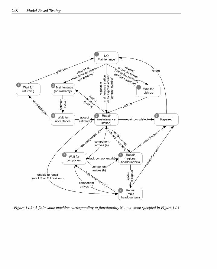
248 Model-Based Testing
NO Maintenance
Maintenance(no warranty)
estim
ate
cost
s
request at
maintenance station
(no warranty)
request by phone or web
[US or EU resident]
(contract number)
Wait forpick up
Repair(maintenance
station)
pick upre
ques
t at
mai
nten
ance
sta
tion
or b
y ex
pres
s co
urie
r(c
ontra
ct n
umbe
r)
Wait for acceptance
acceptestimate
Wait for returning
reject estimate
pick up
Repairedrepair completed
return
Repair(regional
headquarters)
Repair(main
headquarters)
successf
ul repair
unable to repair
(US or EU resident)
succ
essfu
l rep
air
unable to repair
Wait for component
lack co
mponent (a)
lack component (b)
lack component (c)componentarrives (c)
componentarrives (b)
componentarrives (a)
invalidcontractnumber
unable to repair(not US or EU resident)
1 2 3
0
4 5 6
7 8
9
Figure 14.2: A finite state machine corresponding to functionality Maintenance specified in Figure 14.1
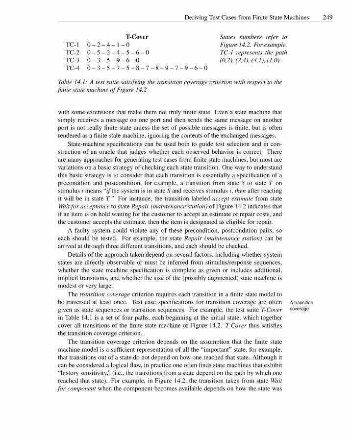
Deriving Test Cases from Finite State Machines 249
T-CoverTC-1 0 – 2 – 4 – 1 – 0TC-2 0 – 5 – 2 – 4 – 5 – 6 – 0TC-3 0 – 3 – 5 – 9 – 6 – 0TC-4 0 – 3 – 5 – 7 – 5 – 8 – 7 – 8 – 9 – 7 – 9 – 6 – 0
States numbers refer toFigure 14.2. For example,TC-1 represents the path(0,2), (2,4), (4,1), (1,0).
Table 14.1: A test suite satisfying the transition coverage criterion with respect to thefinite state machine of Figure 14.2
with some extensions that make them not truly finite state. Even a state machine thatsimply receives a message on one port and then sends the same message on anotherport is not really finite state unless the set of possible messages is finite, but is oftenrendered as a finite state machine, ignoring the contents of the exchanged messages.
State-machine specifications can be used both to guide test selection and in con-struction of an oracle that judges whether each observed behavior is correct. Thereare many approaches for generating test cases from finite state machines, but most arevariations on a basic strategy of checking each state transition. One way to understandthis basic strategy is to consider that each transition is essentially a specification of aprecondition and postcondition, for example, a transition from state S to state T onstimulus i means “if the system is in state S and receives stimulus i, then after reactingit will be in state T .” For instance, the transition labeled accept estimate from stateWait for acceptance to state Repair (maintenance station) of Figure 14.2 indicates thatif an item is on hold waiting for the customer to accept an estimate of repair costs, andthe customer accepts the estimate, then the item is designated as eligible for repair.
A faulty system could violate any of these precondition, postcondition pairs, soeach should be tested. For example, the state Repair (maintenance station) can bearrived at through three different transitions, and each should be checked.
Details of the approach taken depend on several factors, including whether systemstates are directly observable or must be inferred from stimulus/response sequences,whether the state machine specification is complete as given or includes additional,implicit transitions, and whether the size of the (possibly augmented) state machine ismodest or very large.
The transition coverage criterion requires each transition in a finite state model tobe traversed at least once. Test case specifications for transition coverage are often ∆ transition
coveragegiven as state sequences or transition sequences. For example, the test suite T-Coverin Table 14.1 is a set of four paths, each beginning at the initial state, which togethercover all transitions of the finite state machine of Figure 14.2. T-Cover thus satisfiesthe transition coverage criterion.
The transition coverage criterion depends on the assumption that the finite statemachine model is a sufficient representation of all the “important” state, for example,that transitions out of a state do not depend on how one reached that state. Although itcan be considered a logical flaw, in practice one often finds state machines that exhibit“history sensitivity,” (i.e., the transitions from a state depend on the path by which onereached that state). For example, in Figure 14.2, the transition taken from state Waitfor component when the component becomes available depends on how the state was

250 Model-Based Testing
entered. This is a flaw in the model — there really should be three distinct Wait forcomponent states, each with a well-defined action when the component becomes avail-able. However, sometimes it is more expedient to work with a flawed state machinemodel than to repair it, and in that case test suites may be based on more than thesimple transition coverage criterion.
Coverage criteria designed to cope with history sensitivity include single state pathcoverage, single transition path coverage, and boundary interior loop coverage. Eachof these criteria requires execution of paths that include certain subpaths in the FSM.The single state path coverage criterion requires each subpath that traverses states atmost once to be included in a path that is exercised. The single transition path coverage∆ single state path
coverage criterion requires each subpath that traverses transitions at most once to be included ina path that is exercised. The boundary interior loop coverage criterion requires each∆ single transition
path coverage
∆ boundary interiorloop coverage
distinct loop of the state machine to be exercised the minimum, an intermediate, and themaximum or a large number of times1. These criteria may be practical for very smalland simple finite state machine specifications, but since the number of even simplepaths (without repeating states) can grow exponentially with the number of states, theyare often impractical.
Specifications given as finite state machines are typically incomplete: They do notinclude a transition for every possible (state, stimulus) pair. Often the missing transi-tions are implicitly error cases. Depending on the system, the appropriate interpretationmay be that these are don’t care transitions (since no transition is specified, the systemmay do anything or nothing), self transitions (since no transition is specified, the sys-tem should remain in the same state), or (most commonly) error transitions that enter adistinguished state and possibly trigger some error-handling procedure. In at least thelatter two cases, thorough testing includes the implicit as well as the explicit state tran-sitions. No special techniques are required: The implicit transitions are simply addedto the representation before test cases are selected.
The presence of implicit transitions with a don’t care interpretation is typicallyan implicit or explicit statement that those transitions are impossible (e.g., because ofphysical constraints). For example, in the specification of the maintenance procedureof Figure 14.2, the effect of event lack of component is specified only for the states thatrepresent repairs in progress because only in those states might we discover a neededis missing.
Sometimes it is possible to test don’t care transitions even if they are believed tobe impossible in the fielded system, because the system does not prevent the triggeringevent from occurring in a test configuration. If it is not possible to produce test cases forthe don’t care transitions, then it may be appropriate to pass them to other validation orverification activities, for example, by including explicit assumptions in a requirementsor specification document that will undergo inspection.
1The boundary interior path coverage was originally proposed for structural coverage of program controlflow, and is described in Chapter 12.

Testing Decision Structures 251
Terminology: Predicates and ConditionsA predicate is a function with a Boolean (True or False) value. When the input
argument of the predicate is clear, particularly when it describes some property of theinput of a program, we often leave it implicit. For example, the actual representationof account types in an information system might be as three-letter codes, but in a spec-ification we may not be concerned with that representation — we know only that thereis some predicate educational-account that is either True or False .
A basic condition is a single predicate that cannot be decomposed further.A complex condition is made up of basic conditions, combined with Boolean con-
nectives.The Boolean connectives include “and” (∧), “or” (∨), “not” (¬), and several less
common derived connectives such as “implies” and “exclusive or.”
14.3 Testing Decision Structures
Specifications are often expressed as decision structures, such as sets of conditions oninput values and corresponding actions or results. A model of the decision structurecan be used to choose test cases that may reveal discrepancies between the decisionsactually made in the code and the intended decision structure.
The example specification of Figure 14.3 describes outputs that depend on type ofaccount (either educational, or business, or individual), amount of current and yearlypurchases, and availability of special prices. These can be considered as Boolean con-ditions, for example, the condition educational account is either true or false (evenif the type of account is actually represented in some other manner). Outputs can bedescribed as Boolean expressions over the inputs, for example, the output no discountcan be associated with the Boolean expression
( individual account∧¬ current purchase > tier 1 individual threshold∧¬ special offer price < individual scheduled price )
∨ ( business account∧¬ current purchase > tier 1 business threshold∧¬ current purchase > tier 1 business yearly threshold∧¬ special offer price < business scheduled price )
When functional specifications can be given as Boolean expressions, we can applyany of the condition testing approaches described in Chapter 12, Section 12.4. A goodtest suite should at least exercise all elementary conditions occurring in the expression.For simple conditions we might derive test case specifications for all possible combina-tions of truth values of the elementary conditions. For complex formulas, when testingall 2n combinations of n elementary conditions is apt to be too expensive, the modifieddecision/condition coverage criterion (page 12.4) derives a small set of test conditionssuch that each elementary condition independently affects the outcome.
We can produce different models of the decision structure of a specification de-pending on the original specification and on the technique we want to use for deriving

252 Model-Based Testing
Pricing: The pricing function determines the adjusted price of a configuration for a particularcustomer. The scheduled price of a configuration is the sum of the scheduled price ofthe model and the scheduled price of each component in the configuration. The adjustedprice is either the scheduled price, if no discounts are applicable, or the scheduled priceless any applicable discounts.There are three price schedules and three corresponding discount schedules, Business,Educational, and Individual. The Business price and discount schedules apply only if theorder is to be charged to a business account in good standing. The Educational price anddiscount schedules apply to educational institutions. The Individual price and discountschedules apply to all other customers. Account classes and rules for establishing businessand educational accounts are described further in [. . . ].A discount schedule includes up to three discount levels, in addition to the possibility of“no discount.” Each discount level is characterized by two threshold values, a value forthe current purchase (configuration schedule price) and a cumulative value for purchasesover the preceding 12 months (sum of adjusted price).
Educational prices The adjusted price for a purchase charged to an educational account in goodstanding is the scheduled price from the educational price schedule. No further discountsapply.
Business account discounts Business discounts depend on the size of the current purchase aswell as business in the preceding 12 months. A tier 1 discount is applicable if the sched-uled price of the current order exceeds the tier 1 current order threshold, or if total paidinvoices to the account over the preceding 12 months exceeds the tier 1 year cumulativevalue threshold. A tier 2 discount is applicable if the current order exceeds the tier 2 cur-rent order threshold, or if total paid invoices to the account over the preceding 12 monthsexceeds the tier 2 cumulative value threshold. A tier 2 discount is also applicable if boththe current order and 12 month cumulative payments exceed the tier 1 thresholds.
Individual discounts Purchase by individuals and by others without an established account ingood standing is based on current value alone (not on cumulative purchases). A tier 1individual discount is applicable if the scheduled price of the configuration in the currentorder exceeds the tier 1 current order threshold. A tier 2 individual discount is applicableif the scheduled price of the configuration exceeds the tier 2 current order threshold.
Special-price nondiscountable offers Sometimes a complete configuration is offered at a spe-cial, non-discountable price. When a special, nondiscountable price is available for aconfiguration, the adjusted price is the nondiscountable price or the regular price afterany applicable discounts, whichever is less.
Figure 14.3: The functional specification of feature Pricing of the Chipmunk Web site.

Testing Decision Structures 253
test cases. If the original specification is expressed informally as in Figure 14.3, wecan transform it into either a Boolean expression, a graph, or a tabular model beforeapplying a test case generation technique.
Techniques for deriving test case specifications from decision structures were orig-inally developed for graph models, and in particular cause-effect graphs, which havebeen used since the early 1970s. Cause-effect graphs are tedious to derive and do notscale well to complex specifications. Tables, on the other hand, are easy to work withand scale well.
The rows of a decision table represent basic conditions, and columns representcombinations of basic conditions. The last row of the table indicates the expectedoutputs for each combination. Cells of the table are labeled either True , False , ordon’t care (usually written –), to indicate the truth value of the basic condition. Thus,each column is equivalent to a logical expression joining the required values (negated,in the case of False entries) and omitting the basic conditions with don’t care values.2
Decision tables can be augmented with a set of constraints that limit the possiblecombinations of basic conditions. A constraint language can be based on Booleanlogic. Often it is useful to add some shorthand notations for common combinationssuch as at-most-one(C1, . . . , Cn) and exactly-one(C1, . . . , Cn), which are tedious toexpress with the standard Boolean connectives.
Figure 14.4 shows the decision table for the functional specification of feature pric-ing of the Chipmunk Web site presented in Figure 14.3.
The informal specification of Figure 14.3 identifies three customer profiles: ed-ucational, business, and individual. Figure 14.4 has only rows Educational account(EduAc) and Business account (BusAc). The choice individual corresponds to thecombination False , False for choices EduAc and BusAc, and is thus redundant. Theinformal specification of Figure 14.3 indicates different discount policies dependingon the relation between the current purchase and two progressive thresholds for thecurrent purchase and the yearly cumulative purchase. These cases correspond to rows3 through 6 of Figure 14.4. Conditions on thresholds that do not correspond to individ-ual rows in the table can be defined by suitable combinations of values for these rows.Finally, the informal specification of Figure 14.3 distinguishes the cases in which spe-cial offer prices do not exceed either the scheduled or the tier 1 or tier 2 prices. Rows7 through 9 of the table, suitably combined, capture all possible cases of special priceswithout redundancy.
Constraints formalize the compatibility relations among different basic conditionslisted in the table. For example, a cumulative purchase exceeding threshold tier 2 alsoexceeds threshold tier 1.
The basic condition adequacy criterion requires generation of a test case specifi-cation for each column in the table. Don’t care entries of the table can be filled out ∆ basic condition
coveragearbitrarily, as long as constraints are not violated.The compound condition adequacy criterion requires a test case specification for
each combination of truth values of basic conditions. The compound condition ade- ∆ compoundconditioncoverage2The set of columns sharing a label is therefore equivalent to a logical expression in sum-of-products
form.

254 Model-Based Testing
Education IndividualEduAc T T F F F F F FBusAc - - F F F F F FCP > CT1 - - F F T T - -YP > YT1 - - - - - - - -CP > CT2 - - - - F F T TYP > YT2 - - - - - - - -SP > Sc F T F T - - - -SP > T1 - - - - F T - -SP > T2 - - - - - - F TOut Edu SP ND SP T1 SP T2 SP
BusinessEduAc - - - - - - - - - - - -BusAc T T T T T T T T T T T TCP > CT1 F F T T F F T T - - - -YP > YT1 F F F F T T T T - - - -CP > CT2 - - F F - - - - T T - -YP > YT2 - - - - F F - - - - T TSP > Sc F T - - - - - - - - - -SP > T1 - - F T F T - - - - - -SP > T2 - - - - - - F T F T F TOut ND SP T1 SP T1 SP T2 SP T2 SP T2 SP
Constraints
at-most-one(EduAc, BusAc) at-most-one(YP < YT1, YP > YT2)YP > YT2 ⇒ YP > YT1 at-most-one(CP < CT1, CP > CT2)CP > CT2 ⇒ CP > CT1 at-most-one(SP < T1, SP > T2)SP > T2 ⇒ SP > T1
Abbreviations
EduAc Educational account Edu Educational priceBusAc Business account ND No discountCP > CT1 Current purchase greater than threshold 1 T1 Tier 1YP > YT1 Year cumulative purchase greater than threshold 1 T2 Tier 2CP > CT2 Current purchase greater than threshold 2 SP Special PriceYP > YT2 Year cumulative purchase greater than threshold 2SP > Sc Special Price better than scheduled priceSP > T1 Special Price better than tier 1SP > T2 Special Price better than tier 2
Figure 14.4: A decision table for the functional specification of feature Pricing of theChipmunk Web site of Figure 14.3.

Testing Decision Structures 255
quacy criterion generates a number of cases exponential in the number of basic condi-tions (2n combinations for n conditions) and can thus be applied only to small sets ofbasic conditions.
For the modified condition/decision adequacy criterion (MC/DC), each columnin the table represents a test case specification. In addition, for each of the originalcolumns, MC/DC generates new columns by modifying each of the cells containingTrue or False . If modifying a truth value in one column results in a test case specifi- ∆ modified condi-
tion/decisioncoverage
cation consistent with an existing column (agreeing in all places where neither is don’tcare), the two test cases are represented by one merged column, provided they can bemerged without violating constraints.
The MC/DC criterion formalizes the intuitive idea that a thorough test suite wouldnot only test positive combinations of values — combinations that lead to specifiedoutputs — but also negative combinations of values — combinations that differ fromthe specified ones — thus, they should produce different outputs, in some cases amongthe specified ones, in some other cases leading to error conditions.
Applying MC/DC to column 1 of Figure 14.4 generates two additional columns:one for Educational Account = False and Special Price better than scheduled price= False , and the other for Educational Account = True and Special Price better thanscheduled price = True . Both columns are already in the table (columns 3 and 2,respectively) and thus need not be added.
Similarly, from column 2, we generate two additional columns corresponding toEducational Account = False and Special Price better than scheduled price = True ,and Educational Account = True and Special Price better than scheduled price = False ,also already in the table.
Generation of a new column for each possible variation of the Boolean values in thecolumns, varying exactly one value for each new column, produces 78 new columns,21 of which can be merged with columns already in the table. Figure 14.5 shows atable obtained by suitably joining the generated columns with the existing ones. Manydon’t care cells from the original table are assigned either True or False values, toallow merging of different columns or to obey constraints. The few don’t-care entriesleft can be set randomly to obtain a complete test case.
There are many ways of merging columns that generate different tables. The tablein Figure 14.5 may not be the optimal one — the one with the fewest columns. Theobjective in test design is not to find an optimal test suite, but rather to produce acost effective test suite with an acceptable trade-off between the cost of generating andexecuting test cases and the effectiveness of the tests.
The table in Figure 14.5 fixes the entries as required by the constraints, while theinitial table in Figure 14.4 does not. Keeping constraints separate from the table cor-responding to the initial specification increases the number of don’t care entries in theoriginal table, which in turn increases the opportunity for merging columns when gen-erating new cases with the MC/DC criterion. For example, if business account (BusAc)= False , the constraint at-most-one(EduAc, BusAc) can be satisfied by assigning eitherTrue or False to entry educational account. Fixing either choice prematurely may latermake merging with a newly generated column impossible.

256 Model-Based Testing
EduAc T T F F F F F F F F F F F F FBusAc F F F F F F F F T T T T T T TCP > CT1 T T F F T T T T F F T T F F TYP > YT1 F - F - - F T T F F F F T T TCP > CT2 F F F F F F T T F F F F F F FYP > YT2 - - - - - - - - - - - - F F FSP > Sc F T F T F T - - F T F - F T -SP > T1 F T F T F T F T F T F T F T FSP > T2 F - F - F - F T F - F - F - FOut Edu SP ND SP T1 SP T2 SP ND SP T1 SP T1 SP T2
EduAc F F F F F T T T T F -BusAc T T T T T F F F F F FCP > CT1 T T T F F F F T - - FYP > YT1 T F F T T T - - - T TCP > CT2 F T T F F F F T T F FYP > YT2 F - - T T F - - - T FSP > Sc T - T - T F T - - - -SP > T1 T F T F T F - - T T TSP > T2 T F T F T F F F T T -Out SP T2 SP T2 SP Edu SP Edu SP SP SP
Abbreviations
EduAc Educational account Edu Educational priceBusAc Business account ND No discountCP > CT1 Current purchase greater than threshold 1 T1 Tier 1YP > YT1 Year cumulative purchase greater than threshold 1 T2 Tier 2CP > CT2 Current purchase greater than threshold 2 SP Special PriceYP > YT2 Year cumulative purchase greater than threshold 2SP > Sc Special Price better than scheduled priceSP > T1 Special Price better than tier 1SP > T2 Special Price better than tier 2
Figure 14.5: The set of test cases generated for feature Pricing of the Chipmunk Web site applying themodified adequacy criterion.
Deriving Test Cases from Control and Data Flow Graphs 257
14.4 Deriving Test Cases from Control and Data FlowGraphs
Functional specifications are seldom given as control or data flow graphs, but some-times they describe a set of mutually dependent steps to be executed in a given (partial)order, and can thus be modeled with flow graphs.
The specification in Figure 14.6 describes the Chipmunk functionality that preparesorders for shipping. The specification indicates a set of steps to check the validity offields in the order form. Type and validity of some of the values depend on other fieldsin the form. For example, shipping methods are different for domestic and internationalcustomers, and payment methods depend on customer type.
The informal specification in Figure 14.6 can be modeled with a control flow graph,where the nodes represent computations and branches represent control flow consistentwith the dependencies among computations, as illustrated in Figure 14.7. Given acontrol or a data flow graph model, we can generate test case specifications using thecriteria originally devised for structural testing and described in Chapters 12 and 13.
Control flow testing criteria require test cases that exercise all elements of a par-ticular kind in a graph model. The node adequacy criterion requires each node to beexercised at least once, and corresponds to statement testing. It is easy to verify that ∆ node adequacy
criteriontest suite T-node in Figure 14.8, consisting of test case specifications TC-1 and TC-2, causes all nodes of the control flow graph of Figure 14.7 to be traversed, and thusT-node satisfies the node adequacy criterion.
The branch adequacy criterion requires each branch to be exercised at least once:each edge of the graph must be traversed by at least one test case. Test suite T-branch ∆ branch
adequacycriterion
(Figure 14.9) covers all branches of the control flow graph of Figure 14.7 and thussatisfies the branch adequacy criterion.
In principle, other test adequacy criteria described in Chapters 12 and 13 can beapplied to more complex control structures derived from specifications, such as loops.A good functional specification should rarely result in a complex control structure, butdata flow testing may be useful at a much coarser structure (e.g., to test interaction oftransactions through a database).
14.5 Deriving Test Cases from Grammars
Functional specifications for complex documents or domain-specific notations, as wellas for conventional compilers and interpreters, are often structured as an annotatedgrammar or set of regular expressions. Test suites can be systematically derived fromthese grammatical structures.
The informal specification of the Chipmunk Web site advanced search, shown inFigure 14.10, defines the syntax of a search pattern. Not surprisingly, this specificationcan easily be expressed as a grammar. Figure 14.11 expresses the specification as agrammar in Backus Naur Form (BNF).
A second example is given in Figure 14.12, which specifies a product configurationof the Chipmunk Web site. In this case, the syntactic structure of product configuration
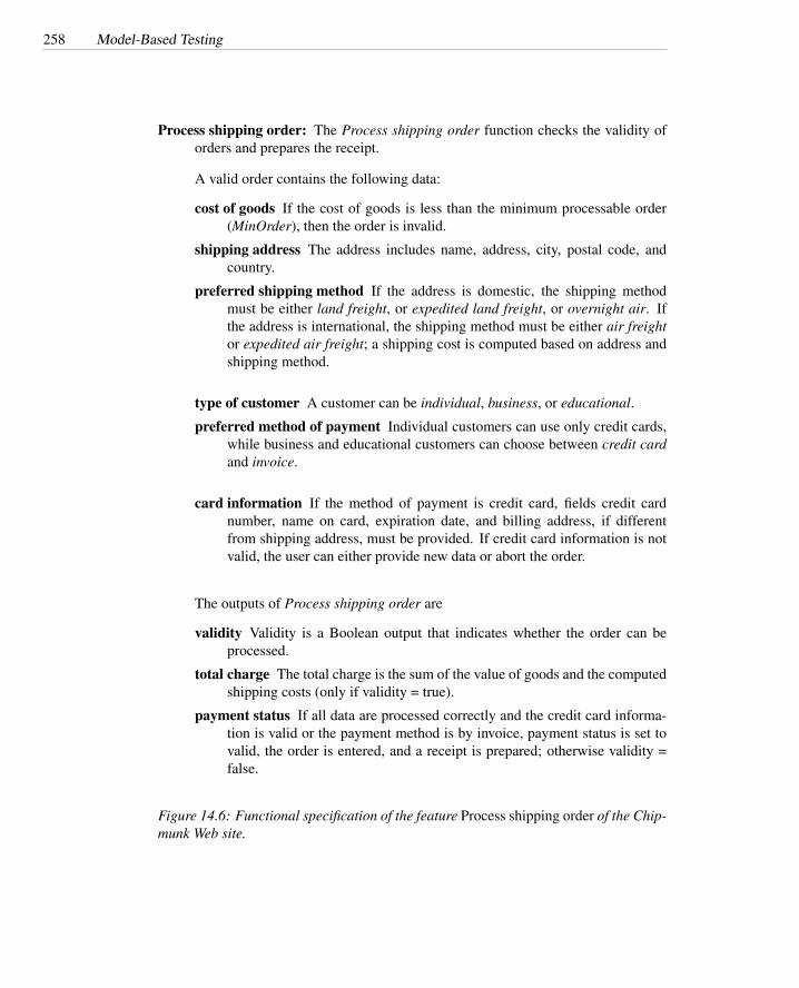
258 Model-Based Testing
Process shipping order: The Process shipping order function checks the validity oforders and prepares the receipt.
A valid order contains the following data:
cost of goods If the cost of goods is less than the minimum processable order(MinOrder), then the order is invalid.
shipping address The address includes name, address, city, postal code, andcountry.
preferred shipping method If the address is domestic, the shipping methodmust be either land freight, or expedited land freight, or overnight air. Ifthe address is international, the shipping method must be either air freightor expedited air freight; a shipping cost is computed based on address andshipping method.
type of customer A customer can be individual, business, or educational.
preferred method of payment Individual customers can use only credit cards,while business and educational customers can choose between credit cardand invoice.
card information If the method of payment is credit card, fields credit cardnumber, name on card, expiration date, and billing address, if differentfrom shipping address, must be provided. If credit card information is notvalid, the user can either provide new data or abort the order.
The outputs of Process shipping order are
validity Validity is a Boolean output that indicates whether the order can beprocessed.
total charge The total charge is the sum of the value of goods and the computedshipping costs (only if validity = true).
payment status If all data are processed correctly and the credit card informa-tion is valid or the payment method is by invoice, payment status is set tovalid, the order is entered, and a receipt is prepared; otherwise validity =false.
Figure 14.6: Functional specification of the feature Process shipping order of the Chip-munk Web site.

Deriving Test Cases from Grammars 259
preferred shipping method = land freight OR expedited land freight OR overnight air
Process shipping order
CostOfGoods < MinOrder
shipping address
no
yes
domestic
preferred shipping method = air freight OR expedited air freight
international
calculate domestic shipping chargecalculate international shipping charge
total charge = goods + shipping
individual customer no
yes
obtain credit card data: number, name on card, expiration date
method of payment
credit card
invoice
billing address = shipping address
obtain billing addressnoyes
valid credit card information
no
yes
payment status = validenter order
prepare receiptinvalid order
nono
abort order?no
yes
Figure 14.7: A control flow graph model corresponding to functionality Process shipping order of Figure14.6.

260 Model-Based Testing
T-node
Case Too Ship Ship Cust Pay Same CCsmall where method type method addr valid
TC-1 No Int Air Bus CC No YesTC-2 No Dom Air Ind CC – No (abort)Abbreviations:Too small CostOfGoods < MinOrder ?Ship where Shipping address, Int = international, Dom = domesticShip how Air = air freight, Land = land freightCust type Bus = business, Edu = educational, Ind = individualPay method CC = credit card, Inv = invoiceSame addr Billing address = shipping address ?CC Valid Credit card information passes validity check?
Figure 14.8: Test suite T-node, comprising test case specifications TC-1 and TC-2,exercises each of the nodes in a control flow graph model of the specification in Fig-ure 14.6.
T-branch
Case Too Ship Ship Cust Pay Same CCsmall where method type method addr valid
TC-1 No Int Air Bus CC No YesTC-2 No Dom Land – – – –TC-3 Yes – – – – – –TC-4 No Dom Air – – – –TC-5 No Int Land – – – –TC-6 No – – Edu Inv – –TC-7 No – – – CC Yes –TC-8 No – – – CC – No (abort)TC-9 No – – – CC – No (no abort)Abbreviations:Too small CostOfGoods < MinOrder ?Ship where Shipping address, Int = international, Dom = domesticShip how Air = air freight, Land = land freightCust type Bus = business, Edu = educational, Ind = individualPay method CC = credit card, Inv = invoiceSame addr Billing address = shipping address ?CC Valid Credit card information passes validity check?
Figure 14.9: Test suite T-branch exercises each of the decision outcomes in a controlflow graph model of the specification in Figure 14.6.

Deriving Test Cases from Grammars 261
Advanced search: The Advanced search function allows for searching elements in the Web sitedatabase.
The key for searching can be:
a simple string, i.e., a simple sequence of characters
a compound string, i.e.,
• a string terminated with character *, used as wild character, or• a string composed of substrings included in braces and separated with com-
mas, used to indicate alternatives
a combination of strings, i.e., a set of strings combined with the Boolean operatorsNOT, AND, OR, and grouped within parentheses to change the priority of oper-ators.
Examples:
laptop The routine searches for string “laptop”
{DVD*,CD*} The routine searches for strings that start with substring “DVD” or “CD”followed by any number of characters.
NOT (C2021*) AND C20* The routine searches for strings that start with substring“C20” followed by any number of characters, except substring “21.”
Figure 14.10: Functional specification of the feature Advanced search of the ChipmunkWeb site.
〈search〉 ::= 〈search〉 〈binop〉 〈term〉 | not 〈search〉 | 〈term〉
〈binop〉 ::= and | or
〈term〉 ::= 〈regexp〉 | ( 〈search〉 )
〈regexp〉 ::= Char 〈regexp〉 | Char | { 〈choices〉 } | *〈choices〉 ::= 〈regexp〉 | 〈regexp〉 , 〈choices〉
Figure 14.11: BNF description of functionality Advanced search.
262 Model-Based Testing
is described by an XML schema, which defines an element Model of type ProductCon-figurationType. XML schemata are essentially a variant of BNF, so it is not difficult torender the schema in the same BNF notation, as shown in Figure 14.11.
Grammars are well suited to represent inputs of varying and unbounded size, withrecursive structures and boundary conditions. These characteristics are not easily ad-dressed with the fixed lists of parameters required by conventional combinatoric tech-niques described in Chapter 11, or by other model-based techniques presented in thischapter.∆ production
coverage criterion Generating test cases from grammar specifications is straightforward and can easilybe automated. Each test case is a string generated from the grammar. To produce astring, we start from a non terminal symbol and progressively apply productions tosubstitute substrings for non terminals occurring in the current string, until we obtain astring composed only of terminal symbols.
In general, we must choose among several applicable production rules at each step.A simple criterion requires each production to be exercised at least once in producinga set of test cases.
The number and complexity of the generated test cases depend on the order ofapplication of the productions. If we first apply productions with non terminals on theright-hand side, we generate a smaller set of large test cases. First applying productionswith only terminals on the right-hand side generates larger sets of smaller test cases.An algorithm that favors non terminals applied to the BNF for advanced search ofFigure 14.10, exercises all the productions to generate the single test case
not Char {*, Char} and (Char or Char)The derivation tree for this test case is given in Figure 14.14. It shows that each
production of the BNF is exercised at least once.∆ boundaryconditiongrammar-basedcriterion
The simple production coverage criterion is subsumed by a richer criterion thatapplies boundary conditions on the number of times each recursive production is ap-plied successively. To generate test cases for boundary conditions we need to choose aminimum and maximum number of applications of each recursive production and thengenerate a test case for the minimum, maximum, one greater than minimum and onesmaller than maximum. The approach is essentially similar to boundary interior pathtesting of program loops (see Section 12.5 of Chapter 12, page 222), where the “loop”in this case is in repeated applications of a production.
To apply the boundary condition criterion, we need to annotate recursive produc-tions with limits. Names and limits are shown in Figure 14.15, which extends thegrammar of Figure 14.13. Alternatives within compound productions are broken outinto individual productions. Production names are added for reference, and limits areadded to recursive productions. In the example of Figure 14.15, the limit of produc-tions compSeq1 and optCompSeq1 is set to 16; we assume that each model can have atmost 16 required and 16 optional components.
The boundary condition grammar-based criterion would extend the minimal set byadding test cases that cover the following choices:
• zero required components (compSeq1 applied 0 times)
• one required component (compSeq1 applied 1 time)

Deriving Test Cases from Grammars 263
1 <?xml version="1.0" encoding="ISO-8859-1" ?>
2 <xsd:schema xmlns:xsd="http://www.w3.org/2000/08/XMLSchema">
3
4 <xsd:annotation>
5 <xsd:documentation>
6 Chipmunk Computers - Product Configuration Schema7 Copyright 2001 D. Seville, Chipmunk Computers Inc.8 </xsd:documentation>
9 </xsd:annotation>
10
11 <xsd:element name="Model" type="ProductConfigurationType"/>12
13 <xsd:complexType name="ProductConfigurationType">
14 <xsd:attribute name="modelNumber"15 type="xsd:string" use="required"/>16 <xsd:element name="Component"17 minoccurs="0" maxoccurs="unbounded">
18 <xsd:sequence>
19 <xsd:element name="ComponentType" type="string"/>20 <xsd:element name="ComponentValue" type="string"/>21 </xsd:sequence>
22 </xsd:element>23 <xsd:element name="OptionalComponent"24 minoccurs="0" maxoccurs="unbounded">
25 <xsd:element name="ComponentType" type="string"/>26 </xsd:element>27 </xsd:complexType>
28 </xsd:schema>
Figure 14.12: An XML schema description of a Product configuration on the Chip-muk Web site. Items are enclosed in matching tags (〈tag〉 text 〈/tag〉) or incorpo-rated in a self-terminating tag (〈tag attribute=”value” /〉). The schema describestype ProductConfigurationType as a tuple composed of a required field modelNumberof type string; a set (possibly empty) of Components, each of which is composed oftwo string-valued fields ComponentType and ComponentValue; and a possibly emptyset of OptionalComponents, each of which is composed of a single string-valuedComponentType.

264 Model-Based Testing
〈Model〉 ::= 〈modelNumber〉 〈compSequence〉 〈optCompSequence〉
〈compSequence〉 ::= 〈Component〉 〈compSequence〉 | empty
〈optCompSequence〉 ::= 〈OptionalComponent〉 〈optCompSequence〉 | empty
〈Component〉 ::= 〈ComponentType〉 〈ComponentValue〉
〈OptionalComponent〉 ::= 〈ComponentType〉
〈modelNumber〉 ::= string
〈ComponentType〉 ::= string
〈ComponentValue〉 ::= string
Figure 14.13: BNF description of Product configuration.
<search>
<search> <binop> <term>
not <search> and (<search>)
<term>
<regexp>
Char <regexp>
<regexp> , <choices>
*
Char
or
{<choices>}
<regexp>
<term>
<search> <binop> <term>
<regexp>
Char
<regexp>
Char
Figure 14.14: The derivation tree of a test case for functionality Advanced Searchderived from the BNF specification of Figure 14.11.
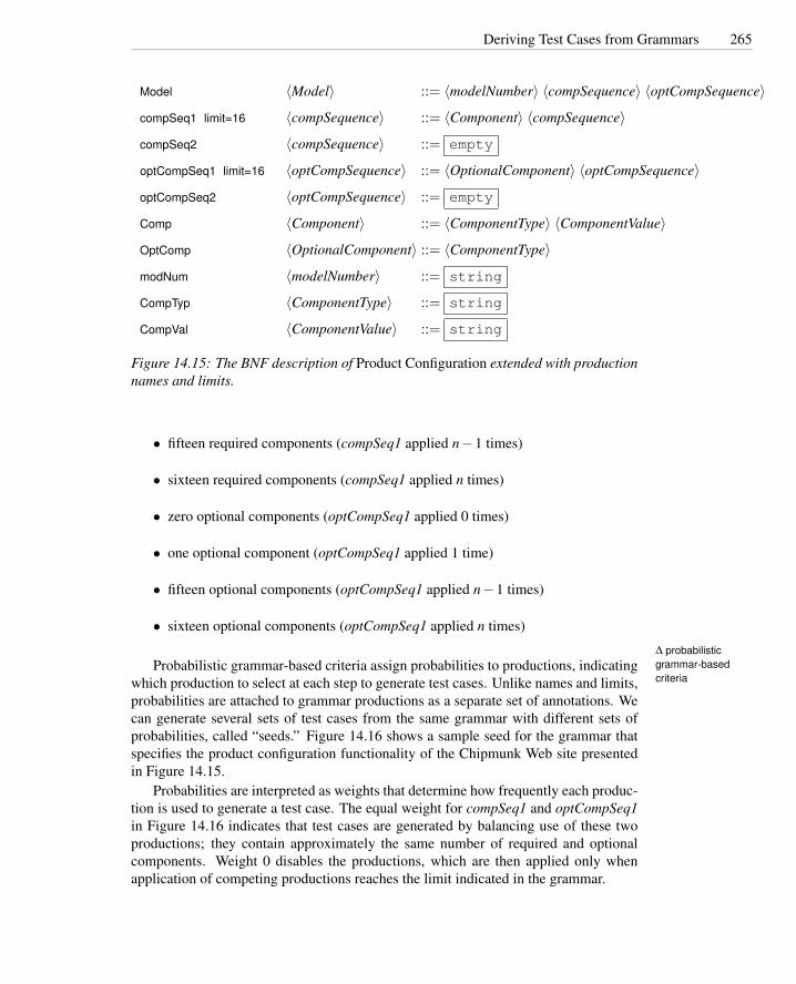
Deriving Test Cases from Grammars 265
Model 〈Model〉 ::= 〈modelNumber〉 〈compSequence〉 〈optCompSequence〉
compSeq1 limit=16 〈compSequence〉 ::= 〈Component〉 〈compSequence〉
compSeq2 〈compSequence〉 ::= empty
optCompSeq1 limit=16 〈optCompSequence〉 ::= 〈OptionalComponent〉 〈optCompSequence〉
optCompSeq2 〈optCompSequence〉 ::= empty
Comp 〈Component〉 ::= 〈ComponentType〉 〈ComponentValue〉
OptComp 〈OptionalComponent〉 ::= 〈ComponentType〉
modNum 〈modelNumber〉 ::= string
CompTyp 〈ComponentType〉 ::= string
CompVal 〈ComponentValue〉 ::= string
Figure 14.15: The BNF description of Product Configuration extended with productionnames and limits.
• fifteen required components (compSeq1 applied n−1 times)
• sixteen required components (compSeq1 applied n times)
• zero optional components (optCompSeq1 applied 0 times)
• one optional component (optCompSeq1 applied 1 time)
• fifteen optional components (optCompSeq1 applied n−1 times)
• sixteen optional components (optCompSeq1 applied n times)
∆ probabilisticgrammar-basedcriteria
Probabilistic grammar-based criteria assign probabilities to productions, indicatingwhich production to select at each step to generate test cases. Unlike names and limits,probabilities are attached to grammar productions as a separate set of annotations. Wecan generate several sets of test cases from the same grammar with different sets ofprobabilities, called “seeds.” Figure 14.16 shows a sample seed for the grammar thatspecifies the product configuration functionality of the Chipmunk Web site presentedin Figure 14.15.
Probabilities are interpreted as weights that determine how frequently each produc-tion is used to generate a test case. The equal weight for compSeq1 and optCompSeq1in Figure 14.16 indicates that test cases are generated by balancing use of these twoproductions; they contain approximately the same number of required and optionalcomponents. Weight 0 disables the productions, which are then applied only whenapplication of competing productions reaches the limit indicated in the grammar.

266 Model-Based Testing
weight Model 1weight compSeq1 10weight compSeq2 0weight optCompSeq1 10weight optCompSeq2 0weight Comp 1weight OptComp 1weight modNum 1weight CompTyp 1weight CompVal 1
Figure 14.16: Sample seed probabilities for BNF productions of Product configuration.
Open Research Issues
As long as there have been models of software, there has been model-based testing.A recent and ongoing ferment of activity in model-based testing is partly the resultof wider use of models throughout software development. Ongoing research will cer-tainly include test design based on software architecture, domain-specific models, andmodels of emerging classes of systems such as service-oriented architectures and adap-tive systems, as well as additional classes of systems and models that we cannot yetanticipate.
As well as following the general trend toward greater use of models in develop-ment, though, research in model-based testing reflects greater understanding of thespecial role that models of software can play in test design and in combining conven-tional testing with analysis. A model is often the best way — perhaps the only way— to divide one property to be verified into two, one part that is best verified withstatic analysis and another part that is best verified with testing. Conformance testingof all kinds exploits models in this way, focusing analysis techniques where they aremost necessary (e.g., nondeterministic scheduling decisions in concurrent software)and using testing to cost-effectively verify consistency between model and program.
Models are also used to specify and describe system structure at levels of orga-nization beyond those that are directly accommodated in conventional programminglanguages (e.g., components and subsystems). Analysis, and to a lesser extent testing,have been explicit concerns in development of architecture description languages. Stillthere remains a divide between models developed primarily for people to communicateand record design decisions (e.g., UML) and models developed primarily for verifica-tion (e.g., various FSM notations). Today we see a good deal of research re-purposingdesign models for test design, which involves adding or disambiguating the semanticsof notations intended for human communication. A challenge for future design nota-tions is to provide a better foundation for analysis and testing without sacrificing thecharacteristics that make them useful for communicating and recording design deci-sions.
An important issue in modeling, and by extension in model-based testing, is how

Deriving Test Cases from Grammars 267
to use multiple model “views” to together form a comprehensive model of a program.More work is needed on test design that uses more than one modeling view, or on thepotential interplay between test specifications derived from different model views ofthe same program.
As with many other areas of software testing and analysis, more empirical researchis also needed to characterize the cost and effectiveness of model-based testing ap-proaches. Perhaps even more than in other areas of testing research, this is not only amatter of carrying out experiments and case studies, but is at least as much a matter ofunderstanding how to pose questions that can be effectively answered by experimentsand whose answers generalize in useful ways.
Further Reading
Myers’ classic text [Mye79] describes a number of techniques for testing decisionstructures. Richardson, O’Malley, and Tittle [ROT89] and Stocks and Carrington[SC96] among others attempt to generate test cases based on the structure of (formal)specifications. Beizer’s Black Box Testing [Bei95] is a popular presentation of tech-niques for testing based on control and data flow structure of (informal) specifications.
Test design based on finite state machines has long been important in the do-main of communication protocol development and conformance testing; Fujiwara, vonBochmann, Amalou, and Ghedamsi [FvBK+91] is a good introduction. Gargantiniand Heitmeyer [GH99] describe a related approach applicable to software systems inwhich the finite state machine is not explicit but can be derived from a requirementsspecification.
Generating test suites from context-free grammars is described by Celentano etal. [CCD+80] and apparently goes back at least to Hanford’s test generator for anIBM PL/I compiler [Han70]. The probabilistic approach to grammar-based testing isdescribed by Sirer and Bershad [SB99], who use annotated grammars to systematicallygenerate tests for Java virtual machine implementations.
Heimdahl et al. [HDW04] provide a cautionary note regarding how naive model-based testing can go wrong, while a case study by Pretschner et al. [PPW+05] suggeststhat model based testing is particularly effective in revealing errors in informal specifi-cations.
Related Topics
Readers interested in testing based on finite state machines may proceed to Chapter 15,in which finite state models are applied to testing object-oriented programs.

268 Model-Based Testing
Exercises
14.1. Derive sets of test cases for functionality Maintenance from the FSM specifica-tion in Figure 14.2.
(a) Derive a test suite that satisfies the Transition Coverage criterion.
(b) Derive a test suite that satisfies the Single State Path Coverage criterion.
(c) Indicate at least one element of the program that must be covered by a testsuite satisfying the Single Transition Path Coverage, but need not be cov-ered by a test suite that satisfies the Single State Path Coverage criterion.Derive a test case that covers that element.
(d) Describe at least one element that must be covered by a test suite that satis-fies both the Single Transition Path Coverage and Boundary Interior LoopCoverage criteria, but need not be covered by a test suite that satisfies theTransition Coverage and Single State Path Coverage criteria. Derive a testcase that covers that element.
14.2. Discuss how the test suite derived for functionality Maintenance applying Tran-sition Coverage to the FSM specification of Figure 14.2 (Exercise 14.1) must bemodified under the following assumptions.
(a) How must it be modified if the implicit transitions ar error conditions?
(b) How must it be modified if the implicit transitions are self-transitions?
14.3. Finite state machine specifications are often augumented with variables that maybe tested and changed by state transitions. The same system can often be de-scribed by a machine with more or fewer states, depending on how much in-formation is represented by the states themselves and how much is representedby extra variables. For example, in Figure 5.9 (page 69), the state of the buffer(empty or not) is represented directly by the states, but we could also representthat information with a variable empty and merge states Empty buffer and Withinline of the finite state machine into a single Gathering state to obtain a morecompact finite state machine, as in this diagram:
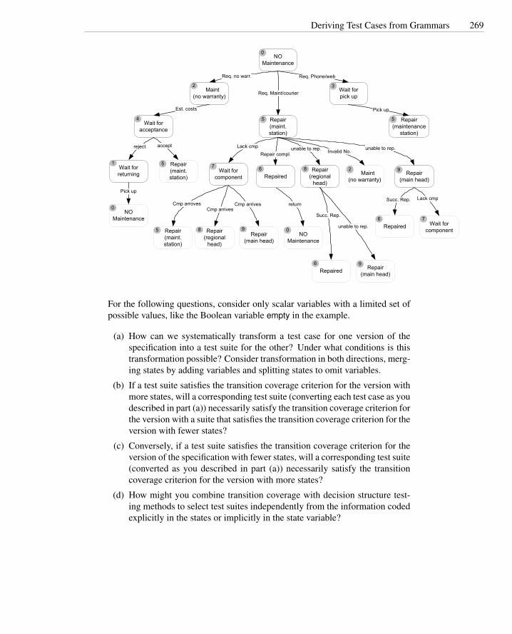
Deriving Test Cases from Grammars 269
returnCmp arrivesCmp arrives
Cmp arroves
unable to rep.
Maint(no warranty)
2
NO Maintenance
0
Wait forpick up
3
Wait for acceptance
4
NO Maintenance
0
Wait for returning
1
Repair(maintenance
station)
5
Repaired6Wait for
component
7Repair
(main head)
9Repair(regional
head)
8
Repair(maint. station)
5
Repair(maint. station)
5
Maint(no warranty)
2
unable to rep.Lack cmp
NO Maintenance
0Repair(maint. station)
5 Repair(regional
head)
8Repair
(main head)
9 Repaired6
Wait for component
7
Invalid No.
Repair(main head)
9Repaired
6
Lack cmpSucc. Rep.
Succ. Rep.
unable to rep.
Pick up
Repair compl.
Pick up
acceptreject
Est. costs
Req. no warr.
Req. Maint/courier
Req. Phone/web
For the following questions, consider only scalar variables with a limited set ofpossible values, like the Boolean variable empty in the example.
(a) How can we systematically transform a test case for one version of thespecification into a test suite for the other? Under what conditions is thistransformation possible? Consider transformation in both directions, merg-ing states by adding variables and splitting states to omit variables.
(b) If a test suite satisfies the transition coverage criterion for the version withmore states, will a corresponding test suite (converting each test case as youdescribed in part (a)) necessarily satisfy the transition coverage criterion forthe version with a suite that satisfies the transition coverage criterion for theversion with fewer states?
(c) Conversely, if a test suite satisfies the transition coverage criterion for theversion of the specification with fewer states, will a corresponding test suite(converted as you described in part (a)) necessarily satisfy the transitioncoverage criterion for the version with more states?
(d) How might you combine transition coverage with decision structure test-ing methods to select test suites independently from the information codedexplicitly in the states or implicitly in the state variable?

270 Model-Based Testing

Chapter 15
Testing Object-OrientedSoftware
Systematic testing of object-oriented software is fundamentally similar to systematictesting approaches for procedural software: We begin with functional tests based onspecification of intended behavior, add selected structural test cases based on the soft-ware structure, and work from unit testing and small-scale integration testing towardlarger integration and then system testing. Nonetheless, the differences between pro-cedural software and object-oriented software are sufficient to make specialized tech-niques appropriate.
Required Background
• Chapters 11, 12, 13, and 14
This chapter builds on basic functional, structural, and model-based testing tech-niques, including data flow testing techniques. Some basic techniques, describedmore thoroughly in earlier chapters, are recapped very briefly here to provideflexibility in reading order.
• Chapter 5
Many of the techniques described here employ finite state machines for modelingobject state.
15.1 Overview
Object-oriented software differs sufficiently from procedural software to justify recon-sidering and adapting approaches to software test and analysis. For example, methodsin object-oriented software are typically shorter than procedures in other software, sofaults in complex intraprocedural logic and control flow occur less often and meritless attention in testing. On the other hand, short methods together with encapsula-tion of object state suggest greater attention to interactions among method calls, while
271

272 Testing Object-Oriented Software
polymorphism, dynamic binding, generics, and increased use of exception handlingintroduce new classes of fault that require attention.
Some traditional test and analysis techniques are easily adapted to object-orientedsoftware. For example, code inspection can be applied to object-oriented softwaremuch as it is to procedural software, albeit with different checklists. In this chapter wewill be concerned mostly with techniques that require more substantial revision (likeconventional structural testing techniques) and with the introduction of new techniquesfor coping with problems associated with object-oriented software.
15.2 Issues in Testing Object-Oriented Software
The characteristics of object-oriented software that impact test design are summarizedin the sidebar on page 273 and discussed in more detail below.
The behavior of object-oriented programs is inherently stateful: The behavior ofstate-dependentbehavior a method depends not only on the parameters passed explicitly to the method, but also
on the state of the object. For example, method CheckConfiguration() of class Model,shown in Figure 15.1, returns True or False depending on whether all components arebound to compatible slots in the current object state.
In object-oriented programs, public and private parts of a class (fields and meth-encapsulation
ods) are distinguished. Private state and methods are inaccessible to external entities,which can only change or inspect private state by invoking public methods.1 For ex-ample, the instance variable modelID of class Model in Figure 15.1 is accessible byexternal entities, but slots and legalConfig are accessible only within methods of thesame class. The constructor Model() and the method checkConfiguration() can be usedby external entities to create new objects and to check the validity of the current con-figuration, while method openDB() can be invoked only by methods of this class.
Encapsulated information creates new problems in designing oracles and test cases.Oracles must identify incorrect (hidden) state, and test cases must exercise objects indifferent (hidden) states.
Object-oriented programs include classes that are defined by extending or spe-inheritance
cializing other classes through inheritance. For example, class Model in Figure 15.1extends class CompositeItem, as indicated in the class declaration. A child class caninherit variables and methods from its ancestors, overwrite others, and add yet oth-ers. For example, the class diagram of Figure 15.3 shows that class Model inherits theinstance variables sku, units and parts, and methods validItem(), getUnitPrice() and ge-tExtendedPrice(). It overwrites methods getHeightCm(), getWidthCm(), getDepthCm()and getWeightGm(). It adds the instance variables baseWeight, modelID, heightCm,widthCm, DepthCm, slots and legalConfig, and the methods selectModel(), deselect-Model(), addComponent(), removeComponent() and isLegalConfiguration().
1Object-oriented languages differ with respect to the categories of accessibility they provide. For exam-ple, nothing in Java corresponds exactly to the “friend” functions in C++ that are permitted to access theprivate state of other objects. But while details vary, encapsulation of state is fundamental to the object-oriented programming paradigm, and all major object-oriented languages have a construct comparable toJava’s private field declarations.

Issues in Testing Object-Oriented Software 273
Summary: Relevant Characteristics of Object-Oriented SoftwareState Dependent Behavior: Testing techniques must consider the state in which
methods are invoked. Testing techniques that are oblivious to state (e.g., tradi-tional coverage of control structure) are not effective in revealing state-dependentfaults.
Encapsulation: The effects of executing object-oriented code may include outputs,modification of object state, or both. Test oracles may require access to private(encapsulated) information to distinguish between correct and incorrect behav-ior.
Inheritance: Test design must consider the effects of new and overridden methods onthe behavior of inherited methods, and distinguish between methods that requirenew test cases, ancestor methods that can be tested by reexecuting existing testcases, and methods that do not need to be retested.
Polymorphism and Dynamic Binding: A single method call may be dynamicallybound to different methods depending on the state of the computation. Testsmust exercise different bindings to reveal failures that depend on a particularbinding or on interactions between bindings for different calls.
Abstract Classes: Abstract classes cannot be directly instantiated and tested, yet theymay be important interface elements in libraries and components. It is necessaryto test them without full knowledge of how they may be instantiated.
Exception Handling: Exception handling is extensively used in modern object-oriented programming. The textual distance between the point where an excep-tion is thrown and the point where it is handled, and the dynamic determinationof the binding, makes it important to explicitly test exceptional as well as normalcontrol flow.
Concurrency: Modern object-oriented languages and toolkits encourage and some-times even require multiple threads of control (e.g., the Java user interface con-struction toolkits AWT and Swing). Concurrency introduces new kinds of pos-sible failures, such as deadlock and race conditions, and makes the behavior of asystem dependent on scheduler decisions that are not under the tester’s control.

274 Testing Object-Oriented Software
1 public class Model extends Orders.CompositeItem {2 public String modelID; // Database key for slots3 private int baseWeight; // Weight excluding optional components4 private int heightCm, widthCm, depthCm; // Dimensions if boxed5 private Slot[] slots; // Component slots6
7 private boolean legalConfig = false; // memoized result of isLegalConf8 private static final String NoModel = "NO MODEL SELECTED";
12 . . .13 /** Constructor, which should be followed by selectModel */14 public Model(Orders.Order order) {15 super( order);16 modelID = NoModel;17 }99 . . .
100 /** Is the current binding of components to slots a legal101 * configuration? Memo-ize the result for repeated calls */102 public boolean isLegalConfiguration() {103 if (! legalConfig) {104 checkConfiguration();105 }106 return legalConfig;107 }108
109 /** Are all required slots filled with compatible components?110 * It is impossible to assign an incompatible component,111 * so just to check that every required slot is filled. */112 private void checkConfiguration() {113 legalConfig = true;114 for (int i=0; i < slots.length; ++i) {115 Slot slot = slots[i];116 if (slot.required && ! slot.isBound()) {117 legalConfig = false;118 }119 }120 }241 . . .242 }
Figure 15.1: Part of a Java implementation of class Model.

Issues in Testing Object-Oriented Software 275
1 public class Model extends Orders.CompositeItem {61 . . .62 /** Bind a component to a slot.63 * @param slotIndex Which slot (integer index)?64 * @param sku Key to component database.65 * Choices should be constrained by web interface, so we don’t66 * need to be graceful in handling bogus parameters.67 */68 public void addComponent(int slotIndex, String sku) {69 Slot slot =slots[slotIndex];70 if (componentDB.contains(sku)) {71 Component comp = new Component(order, sku);72 if (comp.isCompatible(slot.slotID)) {73 slot.bind(comp);74 // Note this cannot have made the75 // configuration illegal.76 } else {77 slot.unbind();78 legalConfig = false;79 }80 } else {81 slot.unbind();82 legalConfig = false;83 }84 }85
86
87 /** Unbind a component from a slot. */88 public void removeComponent(int slotIndex) {89 // assert slotIndex in 0..slots.length90 if (slots[slotIndex].isBound()) {91 slots[slotIndex].unbind();92 }93 legalConfig = false;94 }
215 . . .216 }
Figure 15.2: More of the Java implementation of class Model. Because of the waymethod isLegalConfig is implemented (see Figure 15.1), all methods that modify slotsmust reset the private variable legalConfig.

276 Testing Object-Oriented Software
+selectModel()+deselectModel()+addComponent()+removeComponent()+isLegalConfiguration() : boolean+getHeightCm() : integer+getWidthCm() : integer+getDepthCm() : integer+getWeightGm() : integer
-baseWeight : integer+modelID : string-heightCm : integer-widthCm : integer-depthCm : integer-slots : Slot-legalConfig : boolean
Model
+getWeightCm() : integer+getHeightCm() : integer+getWidthCm() : integer+getDepthCm() : integer+isCompatible() : boolean
-weightGm : integer-heightGm : integer-widthCm : integer-depthCm : integer-slotCompat : string
Component
+validItem() : boolean+getUnitPrice() : integer+getExtendedPrice() : integer+getHeightCm() : integer+getWidthCm() : integer+getDepthCm() : integer+getWeightGm() : integer
+sku : string+units : integer
LineItem
+getUnitPrice() : integer+parts : Vector
CompositeItem
+getUnitPrice() : integer
SimpleItem
Figure 15.3: An excerpt from the class diagram of the Chipmunk Web presence thatshows the hierarchy rooted in class LineItem.

Issues in Testing Object-Oriented Software 277
Inheritance brings in optimization issues. Child classes may share several methodswith their ancestors. Sometimes an inherited method must be retested in the child class,despite not having been directly changed, because of interaction with other parts of theclass that have changed. Many times, though, one can establish conclusively that thebehavior of an inherited method is really unchanged and need not be retested. In othercases, it may be necessary to rerun tests designed for the inherited method, but notnecessary to design new tests.
Most object-oriented languages allow variables to dynamically change their type, polymorphism
dynamic bindingas long as they remain within a hierarchy rooted at the declared type of the variable.For example, variable subsidiary of method getYTDPurchased() in Figure 15.4 can bedynamically bound to different classes of the Account hierarchy, and thus the invoca-tion of method subsidiary.getYTDPurchased() can be bound dynamically to differentmethods.
Dynamic binding to different methods may affect the whole computation. Testing acall by considering only one possible binding may not be enough. Test designers needtesting techniques that select subsets of possible bindings that cover a sufficient rangeof situations to reveal faults in possible combinations of bindings.
Some classes in an object-oriented program are intentionally left incomplete and abstract classes
cannot be directly instantiated. These abstract classes2 must be extended through sub-classes; only subclasses that fill in the missing details (e.g., method bodies) can beinstantiated. For example, both classes LineItem of Figure 15.3 and Account of Fig-ure 15.4 are abstract.
If abstract classes are part of a larger system, such as the Chipmunk Web presence,and if they are not part of the public interface to that system, then they can be testedby testing all their child classes: classes Model, Component, CompositeItem, and Sim-pleItem for class LineItem and classes USAccount, UKAccount, JPAccount, EUAccountand OtherAccount for class Account. However, we may need to test an abstract classeither prior to implementing all child classes, for example if not all child classes will beimplemented by the same engineers in the same time frame, or without knowing all itsimplementations, for example if the class is included in a library whose reuse cannotbe fully foreseen at development time. In these cases, test designers need techniquesfor selecting a representative set of instances for testing the abstract class.
Exceptions were originally introduced in programming languages independently exceptions
of object-oriented features, but they play a central role in modern object-oriented pro-gramming languages and in object-oriented design methods. Their prominent role inobject-oriented programs, and the complexity of propagation and handling of excep-tions during program execution, call for careful attention and specialized techniques intesting.
The absence of a main execution thread in object-oriented programs makes them concurrency
well suited for concurrent and distributed implementations. Although many object-oriented programs are designed for and executed in sequential environments, the design
2Here we include the Java interface construct as a kind of abstract class.

278 Testing Object-Oriented Software
1 public abstract class Account {151 . . .152 /**153 * The YTD Purchased amount for an account is the YTD154 * total of YTD purchases of all customers using this account155 * plus the YTD purchases of all subsidiaries of this account;156 * currency is currency of this account.157 */158 public int getYTDPurchased() {159
160 if (ytdPurchasedValid) { return ytdPurchased; }161
162 int totalPurchased = 0;163 for (Enumeration e = subsidiaries.elements() ; e.hasMoreElements(); )164 {165 Account subsidiary = (Account) e.nextElement();166 totalPurchased += subsidiary.getYTDPurchased();167 }168 for (Enumeration e = customers.elements(); e.hasMoreElements(); )169 {170 Customer aCust = (Customer) e.nextElement();171 totalPurchased += aCust.getYearlyPurchase();172 }173 ytdPurchased = totalPurchased;174 ytdPurchasedValid = true;175 return totalPurchased;176 }332 . . .333 }
Figure 15.4: Part of a Java implementation of Class Account. The abstract class isspecialized by the regional markets served by Chipmunk into USAccount, UKAccount,JPAccount, EUAccount and OtherAccount, which differ with regard to shipping meth-ods, taxes, and currency. A corporate account may be associated with several individ-ual customers, and large companies may have different subsidiaries with accounts indifferent markets. Method getYTDPurchased() sums the year-to-date purchases of allcustomers using the main account and the accounts of all subsidiaries.

Issues in Testing Object-Oriented Software 279
Actual Needs and Constraints
System Test
Integration Test
Module Test
User Acceptance (alpha, beta test)
Rev
iew
Analysis / Review
Analysis / Review
User review of external behavior as it is determined or becomes visible
Unit/Components
Subsystem Design/Specs Subsystem
SystemIntegration
SystemSpecifications
DeliveredPackage
A&T Activities that require specific
approaches for OO SW
Unit/Component Specs
Figure 15.5: The impact of object-oriented design and coding on analysis and testing.
of object-oriented applications for concurrent and distributed environments is becom-ing very frequent.
Object-oriented design and programming greatly impact analysis and testing. How-ever, test designers should not make the mistake of ignoring traditional technology andmethodologies. A specific design approach mainly affects detailed design and code, butthere are many aspects of software development and quality assurance that are largelyindependent of the use of a specific design approach. In particular, aspects related toplanning, requirements analysis, architectural design, deployment and maintenance canbe addressed independently of the design approach. Figure 15.5 indicates the scope ofthe impact of object-oriented design on analysis and testing.

280 Testing Object-Oriented Software
15.3 An Orthogonal Approach to Test
Testing all aspects of object-oriented programs simultaneously would be difficult andexpensive; fortunately it is also unnecessary. It is more cost-effective to address dif-ferent features individually, using appropriate techniques for each, and to explicitlyaddress significant interactions (e.g., between inheritance and state-dependent behav-ior) rather than blindly exploring all different feature combinations.
The proper blend of techniques depends on many factors: application under test,development approach, team organization, application criticality, development envi-ronment and the implementation languages, use of design and language features, andproject timing and resource constraints. Nonetheless, we can outline a general ap-proach that works in stages, from single classes to class and system interactions. Asingle “stage” is actually a set of interrelated test design and test execution activities.The approach is summarized in the sidebar on page 281 and described in more detailin this section in the order that tests related to a particular class would be executed,although test design and execution activities are actually interleaved and distributedthrough development.
The smallest coherent unit for unit testing of object-oriented testing is the class.Test designers can address inheritance, state-dependent behavior and exceptions withintraclass testing. For example, when testing class Model of Figure 15.3, test designersmay first use testing histories (see Section 15.10) to infer that method getExtendedPriceneed not be retested, since it has already been tested in class LineItem. On the otherhand, test designers must derive new test cases for the new methods and for thoseaffected by the modifications introduced in class Model.
After considering individual methods, test designers can proceed to design func-tional test cases from the statechart specification of class Model (see Section 15.5)and structural test cases from data flow information (see Section 15.7). To executetest cases, test designers may decide to use equivalent scenarios as oracles (see Sec-tion 15.8). Test designers will then create test cases for exceptions thrown or handledby the class under test (see Section 15.12). Class Model does not make polymorphiccalls, so no additional test cases need be designed to check behavior with variablebindings to different classes.
Integration (interclass) tests must be added to complete the testing for hierarchy,polymorphism, and exception-related problems. For example, when testing integrationof class Model within the Chipmunk Web presence, test designers will identify classSlot as a predecessor in the integration order and will test it first, before testing itsintegration with class Model (see Sections 15.5 and 15.7). They will also derive testcases for completing the test of exceptions (see Section 15.12) and polymorphism (seeSection 15.9).
System and acceptance testing check overall system behavior against user and sys-tem requirements. Since these requirements are (at least in principle) independent ofthe design approach, system and acceptance testing can be addressed with traditionaltechniques. For example, to test the business logic subsystem of the Chipmunk Webpresence, test designers may decide to derive test cases from functional specificationsusing category-partition and catalog based methods (see Chapter 11).

An Orthogonal Approach to Test 281
Steps in Object-Oriented Software TestingObject-oriented testing can be broken into three phases, progressing from individualclasses toward consideration of integration and interactions.
Intraclass: Testing classes in isolation (unit testing)
1. If the class-under-test is abstract, derive a set of instantiations to cover sig-nificant cases. Instantiations may be taken from the application (if avail-able) and/or created just for the purpose of testing.
2. Design test cases to check correct invocation of inherited and overriddenmethods, including constructors. If the class-under-test extends classes thathave previously been tested, determine which inherited methods need to beretested and which test cases from ancestor classes can be reused.
3. Design a set of intraclass test cases based on a state machine model ofspecified class behavior.
4. Augment the state machine model with structural relations derived fromclass source code and generate additional test cases to cover structural fea-tures.
5. Design an initial set of test cases for exception handling, systematicallyexercising exceptions that should be thrown by methods in the class undertest and exceptions that should be caught and handled by them.
6. Design an initial set of test cases for polymorphic calls (calls to superclassor interface methods that can be bound to different subclass methods de-pending on instance values).
Interclass: Testing class integration (integration testing)
1. Identify a hierarchy of clusters of classes to be tested incrementally.
2. Design a set of functional interclass test cases for the cluster-under-test.
3. Add test cases to cover data flow between method calls.
4. Integrate the intraclass exception-handling test sets with interclassexception-handling test cases for exceptions propagated across classes.
5. Integrate the polymorphism test sets with tests that check for interclassinteractions of polymorphic calls and dynamic bindings.
System and Acceptance: Apply standard functional and acceptance testing tech-niques to larger components and the whole system.

282 Testing Object-Oriented Software
15.4 Intraclass Testing
Unit and integration testing aim to expose faults in individual program units and intheir interactions, respectively. The meaning of “unit” is the smallest developmentwork assignment for a single programmer that can reasonably be planned and tracked.In procedural programs, individual program units might be single functions or smallsets of strongly related functions and procedures, often included in a single file ofsource code. In object-oriented programs, small sets of strongly related functions orprocedures are naturally identified with classes, which are generally the smallest workunits that can be systematically tested.
Treating an individual method as a unit is usually not practical because methods ina single class interact by modifying object state and because the effect of an individualmethod is often visible only through its effect on other methods. For example, methodcheck configuration of class computer, shown in Figure 15.1, can be executed only ifthe object is in a given state, and its result depends on the current configuration. Themethod may execute correctly in a given state (i.e., for a given configuration), butmay not execute correctly in a different state (e.g., accepting malformed configurationsor rejecting acceptable configurations). Moreover, method check configuration mightproduce an apparently correct output (return value) but leave the object in an incorrectstate.
15.5 Testing with State Machine Models
Since the state of an object is implicitly part of the input and output of methods, weneed a way to systematically explore object states and transitions. This can be guidedby a state machine model, which can be derived from module specifications.
A state machine model can be extracted from an informal, natural language speci-fication of intended behavior, even when the specification does not explicitly describestates and transitions. States can be inferred from descriptions of methods that act dif-ferently or return different results, depending on the state of the object; this includesany description of when it is allowable to call a method. Of course, one wants to deriveonly a reasonable number of abstract states as representatives of a much larger numberof concrete states, and some judgment is required to choose the grouping. For example,if an object kept an integer count, we might choose “zero” and “nonzero” as representa-tive states, rather than creating a different state for every possible value. The principleto observe is that we are producing a model of how one method affects another, so thestates should be refined just enough to capture interactions. Extracting a state machinefrom an informal specification, and then creating test cases (sequences of method calls)to cover transitions in that model, are illustrated in the sidebar on page 283.
Sometimes an explicit state machine model is already available as part of a specifi-cation or design. If so, it is likely to be in the form of a statechart (also known as a statestatechart (state
diagram) diagram in the UML family of notations). Statecharts include standard state transitiondiagrams, but also provide hierarchical structuring constructs. The structuring facilitiesof statecharts can be used to organize and hide complexity, but this complexity must beexposed to be tested.

Testing with State Machine Models 283
From Informal Specs to Transition CoverageAn Informal Specification of Class Slot
Slot represents a configuration choice in all instances of a particular model of computer.It may or may not be implemented as a physical slot on a bus. A given model may havezero or more slots, each of which is marked as required or optional. If a slot is marked as“required,” it must be bound to a suitable component in all legal configurations.
Class Slot offers the following services:
Incorporate: Make a slot part of a model, and mark it as either required or optional. Allinstances of a model incorporate the same slots.Example: We can incorporate a required primary battery slot and an optional sec-ondary battery slot on the Chipmunk C20 laptop that includes two battery slots. TheC20 laptop may then be sold with one battery or two batteries, but it is not soldwithout at least the primary battery.
Bind: Associate a compatible component with a slot. Example: We can bind slot primarybattery to a Blt4, Blt6, or Blt8 lithium battery or to a Bcdm4 nickel cadmium battery.We cannot bind a disk drive to the battery slot.
Unbind: The unbind operation breaks the binding of a component to a slot, reversing theeffect of a previous bind operation.
IsBound: Returns true if a component is currently bound to a slot, or false if the slot iscurrently empty.
The Corresponding Finite State Machine
A simple analysis of the informal specification of class Slot allows one to identify states andtransitions. Often an analysis of natural language specifications will reveal ambiguities that mustbe resolved one way or the other in the model; these may suggest additional test cases to checkthe interpretation, or lead to refinement of the specification, or both. For class slot, we infer thatthe bind operation makes sense only after the slot has been incorporated in a model, and that it isinitially empty.
Not present Unbound Bound1 20
isBound
isBound
bind
unBind
unBind
incorporate
The Generated Test Case Specifications
A single test case will be given as a sequence of method calls. For class Slot, the followingtest cases suffice to execute each transition in the state machine model:
TC-1 incorporate, isBound, bind, isBoundTC-2 incorporate, unBind, bind, unBind, isBound

284 Testing Object-Oriented Software
modelSelected
workingConfiguration
noModelSelected
validConfiguration
addComponent(slot, component)_________________________
send modelDB: findComponent()send slot:bind()
removeComponent(slot)_________________________
send slot:unbind()
addComponent(slot, component)_________________________
send modelDB: get_component()send slot:bind
deselectModel()selectModel(model)
_________________send modelDB: getModel(modelID,this)
removeComponent(slot)_________________________
send slot:unbind()
CLASS: ModelCLASS: Model
isLegalConfiguration()[legalConfig = true]
Figure 15.6: Statechart specification of class Model.
The most common structuring mechanism in statecharts is grouping of states insuperstates (also called OR-states). A transition from a superstate is equivalent to asuperstate
(OR-state) transition from every state contained within it. A transition to a superstate is equivalentto a transition to the initial state within the superstate. We can obtain an ordinarystate machine by “flattening” the statechart hierarchy, replacing transitions to and fromsuperstates to transitions among elementary states.
Figure 15.6 shows a statechart specification for class Model of the business logic ofthe Chipmunk Web presence. Class Model provides methods for selecting a computermodel and a set of components to fill logical and physical slots. The state model-Selected is decomposed into its two component states, with entries to modelSelecteddirected to the default initial state workingConfiguration.
Table 15.1 shows a set of test cases that cover all transitions of the finite statemachine of Figure 15.7, a flattened version of the statechart of Figure 15.6. Noticethat transition selectModel of the statechart corresponds to a single transition in theFSM, since entry to the superstate is directed to the default initial state, while transitiondeselectModel of the statechart corresponds to two transitions in the FSM, one for eachof the two children states, since the superstate can be exited while in either componentstate.
In covering the state machine model, we have chosen sets of transition sequencesthat together exercise each individual transition at least once. This is the transitionadequacy criterion introduced in Chapter 14. The stronger history-sensitive criteriadescribed in that chapter are also applicable in principle, but are seldom used because

Testing with State Machine Models 285
workingConfiguration
noModelSelected
validConfiguration
addComponent(slot, component)
removeComponent(slot)addComponent(slot, component)
deselectModel()selectModel(model)
removeComponent(slot)
isLegalConfiguration()[legalConfig=false]
deselectModel()
addComponent(slot, component)
addComponent(slot, component)
removeComponent(slot)
isLegalConfiguration()[legalConfig=true]
Figure 15.7: Finite state machine corresponding to the statechart of Figure 15.6.
Test Case TCAselectModel(M1)addComponent(S1,C1)addComponent(S2,C2)isLegalConfiguration()
Test Case TCBselectModel(M1)deselectModel()selectModel(M2)addComponent(S1,C1)addComponent(S2,C2)removeComponent(S1)isLegalConfiguration()
Test Case TCCselectModel(M1)addComponent(S1,C1)removeComponent(S1)addComponent(S1,C2)isLegalConfiguration()
Test Case TCDselectModel(M1)addComponent(S1,C1)addComponent(S2,C2)addComponent(S3,C3)deselectModel()selectModel(M1)addComponent(S1,C1)isLegalConfiguration()
Test Case TCEselectModel(M1)addComponent(S1,C1)addComponent(S2,C2)addComponent(S3,C3)removeComponent(S2)addComponent(S2,C4)isLegalConfiguration()
Table 15.1: A set of test cases that satisfies the transition coverage criterion for thestatechart of Figure 15.6.
286 Testing Object-Oriented Software
of their cost.Even transition coverage may be impractical for complex statecharts. The number
of states and transitions can explode in “flattening” a statechart that represents multiplethreads of control. Unlike flattening of ordinary superstates, which leaves the numberof elementary states unchanged while replicating some transitions, flattening of concur-rent state machines (so-called AND-states) produces new states that are combinationsof elementary states.
Figure 15.8 shows the statechart specification of class Order of the business logicof the Chipmunk Web presence. Figure 15.9 shows the corresponding “flattened” statemachine. Flattening the AND-state results in a number of states equal to the Carte-sian product of the elementary states (3× 3 = 9 states) and a corresponding numberof transitions. For instance, transition add item that exits state not scheduled of thestatechart corresponds to three transitions exiting the states not schedXcanc no fee,not schedXcanc fee, and not schedXnot canc, respectively. Covering all transitions atleast once may result in a number of test cases that exceeds the budget for testing theclass. In this case, we may forgo flattening and use simpler criteria that take advantageof the hierarchical structure of the statechart.
Table 15.2 shows a test suite that satisfies the simple transition coverage adequacycriterion, which requires the execution of all transitions that appear in the statechart.∆ simple transition
coverage The criterion requires that each statechart transition is exercised at least once, but doesnot guarantee that transitions are exercised in all possible states. For example, transitionadd item, which leaves the initial state, is exercised from at least one substate, but notfrom all possible substates as required by the transition coverage adequacy criterion.
15.6 Interclass Testing
Interclass testing is the first level of integration testing for object-oriented software.While intraclass testing focuses on single classes, interclass testing checks interactionsamong objects of different classes. As in integration testing of imperative programs,test designers proceed incrementally, starting from small clusters of classes.
Since the point of interclass testing is to verify interactions, it is useful to modelpotential interactions through a use/include relation. Classes A and B are related by theuse/include relation if objects of class A make method calls on objects of class B, or ifobjects of class A contain references to objects of class B. Inheritance is ignored (wedo not consider a subclass to use or include its ancestors), and abstract classes, whichcannot directly participate in interactions, are omitted. Derivation of the use/includerelation from a conventional UML class diagram is illustrated in Figures 15.10 and15.11.
Interclass testing strategies usually proceed bottom-up, starting from classes thatdepend on no others. The implementation-level use/include relation among classes typ-ically parallels the more abstract, logical depends relation among modules (see sidebaron page 292), so a bottom-up strategy works well with cluster-based testing. For ex-ample, we can start integrating class SlotDB with class Slot, and class Component withclass ComponentDB, and then proceed incrementally integrating classes ModelDB andModel, up to class Order.

Interclass Testing 287
orderInProgress
OrderPlaced
addItem(item, quantity)
package() send priceDB.getScheduledPrice()
cancellableNoFee
notCancellable
cancelled
5daysBeforeShipping()[5daysBeforeshipping = true]
cancel(no_charge)
cancellableFee
24_hours_after_place()[24_hours_after_place()=True]
notScheduled
scheduled
schedule()
shipping
delivered
ship()
__addressUnknown()__ send customer.undelivered(),
send account.charge()
______deliver()______send account.charge()
orderCompleted
readyForShipping
purchase()[purchase = OK]
removeItem(item, quantity)
computeDiscount_____________________________________send customer.getDiscount(scheduledPrice)
computeShippingCosts____________________________________send priceDB.getShippingCost(shipMeans)
placeOrder() [placeOrder=OK]send order.startTimer()
cancel(shipRestockCharge)
suspend()
addItem(item, quantity)
removeItem(item, quantity)
5daysBeforeshipping()[5daysBeforeShipping = true]
CLASS: OrderCLASS: Order
addressUnknown()
Figure 15.8: Statechart specification of class Order. This is a conceptual model inwhich both methods of class Order and method calls by class Order are representedas transitions with names that differ from method names in the implementation (e.g.,5DaysBeforeShipping is not a legal method or field name).

288 Testing Object-Oriented Software
orderInProgress
additem remove
item
package
cancel(no_charge)
addressunknown
deliver
orderCompleted
readyForShipping
additem
purchase
removeitem
getdiscount
getshippingcost
place_order
cancel(charge)
additem remove
item
additem
removeitem
not_schedXcanc_no_fee
not_schedXcanc_fee
not_schedXnot_canc
schedXcanc_no_fee
schedXcanc_fee
schedXnot_canc
shipXcanc_no_fee
shipXcanc_fee
shipXnot_canc
additem
removeitem
additemremove
item
schedule
schedule
schedule
suspend
suspend
suspend
ship
ship
ship
cancel(no_charge)
cancel(no_charge)
deliver
deliver
cancel(charge)
cancel(charge)
24_hours
24_hours
24_hours
5_days
5_days
5_days
5_days
5_days
5_days
cancelleddelivered
Figure 15.9: Finite state machine corresponding to the statechart of Figure 15.8.

Interclass Testing 289
Test Case TCAadd item()add item()package()get shipping cost()get discount()purchase()place order()24 hours()5 days()schedule()ship()deliver()
Test Case TCBadd item()add item()remove item()add item()package()get shipping cost()get discount()purchase()place order()24 hours()5 days()schedule()ship()deliver()
Test Case TCCadd item()add item()package()get shipping cost()get discount()purchase()place order()add item()package()get shipping cost()get discount()purchase()place order()
24 hours()5 days()schedule()ship()deliver()
Test Case TCDadd item()add item()package()get shipping cost()get discount()purchase()place order()remove item()add item()package()get shipping cost()get discount()
purchase()place order()24 hours()5 days()schedule()ship()deliver()
Test Case TCEadd item()add item()package()get shipping cost()get discount()purchase()place order()schedule()suspend()5 days()schedule()ship()deliver()
Test Case TCFadd item()add item()package()get shipping cost()get discount()purchase()place order()schedule()cancel()
Test Case TCGadd item()add item()package()get shipping cost()get discount()purchase()place order()schedule()ship()address unknown()
Test Case TCHadd item()add item()package()get shipping cost()get discount()purchase()place order()schedule()5 days()address unknown()
Test Case TCIadd item()add item()package()get shipping cost()get discount()purchase()place order()schedule()24 hours()cancel()
Table 15.2: A test suite that satisfies the simple transition coverage adequacy crite-rion for the statechart of Figure 15.8. Transitions are indicated without parameters forsimplicity.

290 Testing Object-Oriented Software
OrderCustomer
1 *
LineItem
1
*
Account
1 0..*
Model Component
Slot
SimpleItem
1 * 1 0..1
USAccount
UKAccountJPAccount EUAccount
OtherAccount
Package
1 *
ModelDB
CompositeItem
PriceList
**
**
*
1
CustomerCare
*
*
CSVdb
ComponentDBSlotDB
*1
*
1
Figure 15.10: Part of a class diagram of the Chipmunk Web presence. Classes Account,LineItem, and CSVdb are abstract.

Interclass Testing 291
Order
Customer
Model Component
Slot
USAccount
UKAccountJPAccount EUAccount
OtherAccount
Package
ModelDB
PriceList
CustomerCare
ComponentDB
SlotDB
Figure 15.11: Use/include relation for the class diagram in Figure 15.10. Abstractclasses are not included. Two classes are related if one uses or includes the other.Classes that are higher in the diagram include or use classes that are lower in thediagram.

292 Testing Object-Oriented Software
DependenceThe hierarchy of clusters for interclass testing is based on a conceptual relation of
dependence, and not directly on concrete relations among implementation classes (orimplementation-level design documentation).
Module A depends on module B if the functionality of B must be present for thefunctionality of A to be provided.
If A and B are implemented as classes or clusters of closely related classes, it islikely that the logical depends relation will be reflected in concrete relations amongthe classes. Typically, the class or classes in A will either call methods in the class orclasses in B, or classes in A will have references to classes in B forming a containsrelation among their respective objects.
Concrete relations among classes do not always indicate dependence. It is commonfor contained objects to have part-of relations with their ancestors in the containmenthierarchy, but the dependence is normally from container to contained object and notvice versa. It is also common to find calls from framework libraries to methods thatuse those libraries. For example, the SAX API for parsing XML is an event-drivenparsing framework, which means the parsing library makes calls (through interfaces)on methods provided by the application. This style of event handling is most familiarto Java programmers through the standard Java graphical user interface libraries. It isclear that the application depends on the library and not vice versa.
The depends relation is as crucial to other software development processes as it isto testing. It is essential to building a system as a set of incremental releases, and toscheduling and managing the construction of each release. The depends relation maybe documented in UML package diagrams, and even if not documented explicitly itis surely manifest in the development build order. Test designers may (and probablyshould) be involved in defining the build order, but should not find themselves in theposition of discovering or re-creating it after the fact.
Well-designed systems normally have nearly acyclic dependence relations, withdependence loops limited to closely related clusters. When there are larger loops inthe relation, or when a use/include relation among classes runs contrary to the dependsrelation (e.g., an “up-call” to an ancestor in the depends relation), the loop can bebroken by substituting a stub for the ancestor class. Thus, we always work with anacyclic graph of clusters.
In principle, while climbing the dependence relation, a thorough interclass testingshould consider all combinations of possible interactions. If, for example, a test casefor class Order includes a call to a method of class Model, and the called method calls amethod of class Slot, each call should be exercised for all relevant states of the differentclasses, as identified during intraclass testing. However, this suffers from the same kindof combinatorial explosion that makes flattening concurrent state diagrams impractical.We need to select a subset of interactions among the possible combinations of methodcalls and class states. An arbitrary or random selection of interactions may be an ac-ceptable solution, but in addition one should explicitly test any significant interactionscenarios that have been previously identified in design and analysis.
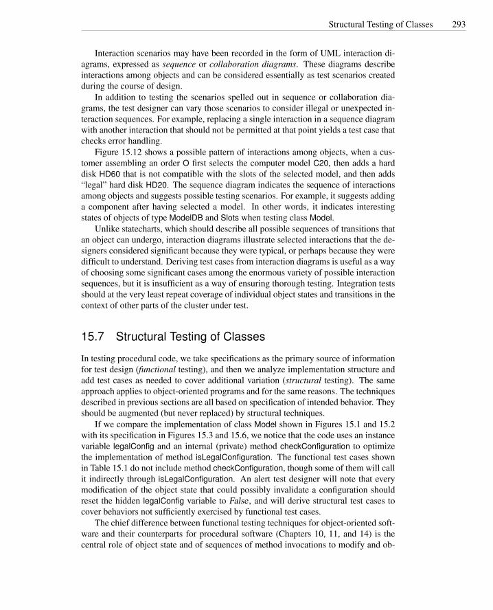
Structural Testing of Classes 293
Interaction scenarios may have been recorded in the form of UML interaction di-agrams, expressed as sequence or collaboration diagrams. These diagrams describeinteractions among objects and can be considered essentially as test scenarios createdduring the course of design.
In addition to testing the scenarios spelled out in sequence or collaboration dia-grams, the test designer can vary those scenarios to consider illegal or unexpected in-teraction sequences. For example, replacing a single interaction in a sequence diagramwith another interaction that should not be permitted at that point yields a test case thatchecks error handling.
Figure 15.12 shows a possible pattern of interactions among objects, when a cus-tomer assembling an order O first selects the computer model C20, then adds a harddisk HD60 that is not compatible with the slots of the selected model, and then adds“legal” hard disk HD20. The sequence diagram indicates the sequence of interactionsamong objects and suggests possible testing scenarios. For example, it suggests addinga component after having selected a model. In other words, it indicates interestingstates of objects of type ModelDB and Slots when testing class Model.
Unlike statecharts, which should describe all possible sequences of transitions thatan object can undergo, interaction diagrams illustrate selected interactions that the de-signers considered significant because they were typical, or perhaps because they weredifficult to understand. Deriving test cases from interaction diagrams is useful as a wayof choosing some significant cases among the enormous variety of possible interactionsequences, but it is insufficient as a way of ensuring thorough testing. Integration testsshould at the very least repeat coverage of individual object states and transitions in thecontext of other parts of the cluster under test.
15.7 Structural Testing of Classes
In testing procedural code, we take specifications as the primary source of informationfor test design (functional testing), and then we analyze implementation structure andadd test cases as needed to cover additional variation (structural testing). The sameapproach applies to object-oriented programs and for the same reasons. The techniquesdescribed in previous sections are all based on specification of intended behavior. Theyshould be augmented (but never replaced) by structural techniques.
If we compare the implementation of class Model shown in Figures 15.1 and 15.2with its specification in Figures 15.3 and 15.6, we notice that the code uses an instancevariable legalConfig and an internal (private) method checkConfiguration to optimizethe implementation of method isLegalConfiguration. The functional test cases shownin Table 15.1 do not include method checkConfiguration, though some of them will callit indirectly through isLegalConfiguration. An alert test designer will note that everymodification of the object state that could possibly invalidate a configuration shouldreset the hidden legalConfig variable to False , and will derive structural test cases tocover behaviors not sufficiently exercised by functional test cases.
The chief difference between functional testing techniques for object-oriented soft-ware and their counterparts for procedural software (Chapters 10, 11, and 14) is thecentral role of object state and of sequences of method invocations to modify and ob-

294 Testing Object-Oriented Software
O:Order C20:Model ChiMod:ModelDB C20Comp:Component ChiSlot:SlotDB ChiComp:ComponentDB
selectModel()
getModel(C20)
extract(C20)
select()
addComponent(HD60)
contains(HD60)
found
isCompatible(HD60)
C20slot:Slots
incompatible
fail
addComponent(HD20)
contains(HD20)
found
isCompatible(HD20)
compatible
success
bind
Figure 15.12: A (partial) sequence diagram that specifies the interactions among ob-jects of type Order, Model, ModelDB, Component, ComponentDB, Slots, and SlotDB,to select a computer, add an illegal component, and then add a legal one.
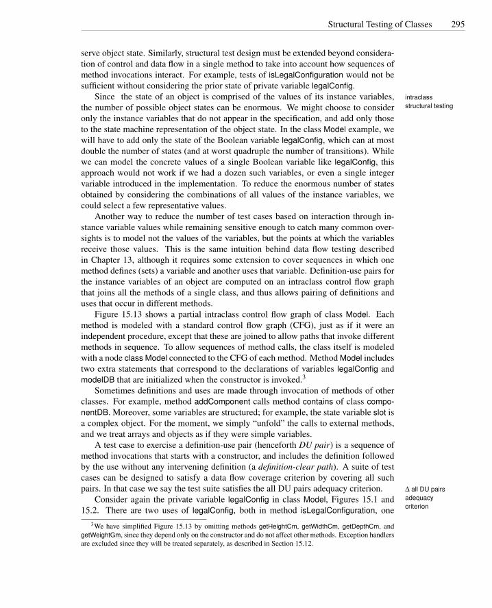
Structural Testing of Classes 295
serve object state. Similarly, structural test design must be extended beyond considera-tion of control and data flow in a single method to take into account how sequences ofmethod invocations interact. For example, tests of isLegalConfiguration would not besufficient without considering the prior state of private variable legalConfig.
Since the state of an object is comprised of the values of its instance variables, intraclassstructural testingthe number of possible object states can be enormous. We might choose to consider
only the instance variables that do not appear in the specification, and add only thoseto the state machine representation of the object state. In the class Model example, wewill have to add only the state of the Boolean variable legalConfig, which can at mostdouble the number of states (and at worst quadruple the number of transitions). Whilewe can model the concrete values of a single Boolean variable like legalConfig, thisapproach would not work if we had a dozen such variables, or even a single integervariable introduced in the implementation. To reduce the enormous number of statesobtained by considering the combinations of all values of the instance variables, wecould select a few representative values.
Another way to reduce the number of test cases based on interaction through in-stance variable values while remaining sensitive enough to catch many common over-sights is to model not the values of the variables, but the points at which the variablesreceive those values. This is the same intuition behind data flow testing describedin Chapter 13, although it requires some extension to cover sequences in which onemethod defines (sets) a variable and another uses that variable. Definition-use pairs forthe instance variables of an object are computed on an intraclass control flow graphthat joins all the methods of a single class, and thus allows pairing of definitions anduses that occur in different methods.
Figure 15.13 shows a partial intraclass control flow graph of class Model. Eachmethod is modeled with a standard control flow graph (CFG), just as if it were anindependent procedure, except that these are joined to allow paths that invoke differentmethods in sequence. To allow sequences of method calls, the class itself is modeledwith a node class Model connected to the CFG of each method. Method Model includestwo extra statements that correspond to the declarations of variables legalConfig andmodelDB that are initialized when the constructor is invoked.3
Sometimes definitions and uses are made through invocation of methods of otherclasses. For example, method addComponent calls method contains of class compo-nentDB. Moreover, some variables are structured; for example, the state variable slot isa complex object. For the moment, we simply “unfold” the calls to external methods,and we treat arrays and objects as if they were simple variables.
A test case to exercise a definition-use pair (henceforth DU pair) is a sequence ofmethod invocations that starts with a constructor, and includes the definition followedby the use without any intervening definition (a definition-clear path). A suite of testcases can be designed to satisfy a data flow coverage criterion by covering all suchpairs. In that case we say the test suite satisfies the all DU pairs adequacy criterion. ∆ all DU pairs
adequacycriterion
Consider again the private variable legalConfig in class Model, Figures 15.1 and15.2. There are two uses of legalConfig, both in method isLegalConfiguration, one
3We have simplified Figure 15.13 by omitting methods getHeightCm, getWidthCm, getDepthCm, andgetWeightGm, since they depend only on the constructor and do not affect other methods. Exception handlersare excluded since they will be treated separately, as described in Section 15.12.

296 Testing Object-Oriented Software
ModelDB modelDB = null
modelDB = NoModel
1.2
Model() 1.1
1.3
1.4
1.5exit Model
3.1
3.2modelID = NoModel
3.3longName = “No...selected”
3.4Slot = null
3.5exit deselectModel
2.1
openDB() 2.2
modelDB getModel(modelID,this) 2.3
exit selectModel 2.4
4.1
4.2
class Model
4.3Component comp = new Component(order,sku)
True
4.4
4.5
False
4.7
True
4.6legalConfig=false
4.10
4.8
False
4.9legalConfig=false;
7.1
7.2
7.3checkConfiguration();
True
7.4return legalConfig
False
5.1void removeComponent (int slotIndex)
5.3slots[slotIndex].unbind
True
5.4legalConfig=false
False
5.2
5.5exit removeComponent
6.1void checkConfiguration()
6.5Slot slot=slots[i]6.9exit checkConfiguration
False
6.2legalConfig=true
6.3int i=0
6.4
6.6++i
6.7
True False
6.8legalConfig=false
True
if(slot.required && !slot.isBound()
if i<slot.length
void deselectModel(String modelID)
void selectModel(String modelID)
void addComponent(int slotIndex, String sku)Slot slot[slotIndex]
if (componentDB contains (sku))
if (Comp.isCompatible(slot,slotID))
exit addComponent
boolean isLegalConfiguratuon()
boolean legalConfig = false
if (!legalConfig)
if (slots[slotIndex].isBound())
slot.unbind();
slot.unbind(); slot.bind(comp);
Figure 15.13: A partial intraclass control flow graph for the implementation of classModel in Figures 15.1 and 15.2.

Structural Testing of Classes 297
in the if and one in the return statement; and there are several definitions in methodsaddComponent, removeComponent, checkConfiguration and in the constructor, whichinitializes legalConfig to False. The all DU pairs adequacy criterion requires a test caseto exercise each definition followed by each use of legalConfig with no interveningdefinitions.
Specifications do not refer to the variable legalConfig and thus do not directly con-sider method interactions through legalConfig or contribute to defining test cases toexercise such interactions. This is the case, for example, in the invocation of methodcheckConfiguration in isLegalConfiguration: The specification suggests that a singleinvocation of method isLegalConfiguration can be sufficient to test the interactions in-volving this method, while calls to method checkConfiguration in isLegalConfigurationindicate possible failures that may be exposed only after two calls of method isLe-galConfiguration. In fact, a first invocation of isLegalConfiguration with value Truefor legalConfig implies a call to checkConfiguration and consequent new definitions oflegalConfig. Only a second call to isLegalConfiguration would exercise the use of thenew value in the if statement, thus revealing failures that may derive from bad updatesof legalConfig in checkConfiguration.
The all DU pairs adequacy criterion ensures that every assignment to a variable istested at each of the uses of that variable, but like other structural coverage criteria itis not particularly good at detecting missing code. For example, if the programmeromitted an assignment to legalConfig, there would be no DU pair connecting the miss-ing assignment to the use. However, assignments to legalConfig are correlated withupdates to slots, and all DU pairs coverage with respect to slots is likely to reveal amissing assignment to the Boolean variable. Correlation among assignments to relatedfields is a common characteristic of the structure of object-oriented software.
Method calls and complex state variables complicate data flow analysis of object-oriented software, as procedure calls and structured variables do in procedural code. interclass
structural testingAs discussed in Chapters 6 and 13, there is no universal recipe to deal with interclasscalls. Test designers must find a suitable balance between costs and benefits.
A possible approach to deal with interclass calls consists in proceeding incremen-tally following the dependence relation, as we did for functional interclass testing.The dependence relation that can be derived from code may differ from the depen-dence relation derived from specifications. However, we can still safely assume thatwell-designed systems present at most a small number of easily breakable cycles. Thedependencies of the implementation and specification of class Model are the same andare shown in Figure 15.11.
Leaf classes of the dependence hierarchy can be analyzed in isolation by identify-ing definitions and uses of instance variables, as just shown. The data flow informationcollected on leaf classes can be summarized by marking methods that access but donot modify the state as Inspectors; methods that modify, but do not otherwise access ∆ inspector
the state, as Modifiers; and methods that both access and modify the state as Inspec- ∆ modifier
tor/Modifiers. ∆ inspector/modifiersWhen identifying inspectors, modifiers and inspector/modifiers, we consider the
whole object state. Thus, we mark a method as inspector/modifier even if it uses justone instance variable and modifies a different one. This simplification is crucial to

298 Testing Object-Oriented Software
scalability, since distinguishing uses and definitions of each individual variable wouldquickly lead to an unmanageable amount of information while climbing the depen-dence hierarchy.
If methods contain more than one execution path, we could summarize the wholemethod as an inspector, modifier, or inspector/modifier, or we could select a subsetof paths to be considered independently. A single method might include Inspector,Modifier, and Inspector/Modifier paths.
Once the data flow information of leaf classes has been summarized, we can pro-ceed with classes that only use or contain leaf classes. Invocations of modifier methodsand inspector/modifiers of leaf classes are considered as definitions. Invocations ofinspectors and inspector/modifiers are treated as uses. When approximating inspec-tor/modifiers as uses, we assume that the method uses the values of the instance vari-ables for computing the new state. This is a common way of designing methods, butsome methods may fall outside this pattern. Again, we trade precision for scalabilityand reduced cost.
We can then proceed incrementally analyzing classes that depend only on classesalready analyzed, until we reach the top of the hierarchy. In this way, each class isalways considered in isolation, and the summary of information at each step preventsexponential growth of information, thus allowing large classes to be analyzed, albeit ata cost in precision.
Figure 15.14 shows the summary information for classes Slot, ModelDB, and Model.The summary information for classes Slot and ModelDB can be used for computingstructural coverage of class Model without unfolding the method calls. The summaryinformation for class Model can be used to compute structural coverage for class Orderwithout knowing the structure of the classes used by class Order. Method checkCon-figuration is not included in the summary information because it is private. The threepaths in checkConfiguration are included in the summary information of the callingmethod isLegalConfiguration.
While summary information is usually derived from child classes, sometimes it isuseful to provide the same information without actually performing the analysis, aswe have done when analyzing class Model. This is useful when we cannot performdata flow analysis on the child classes, as when child classes are delivered as a closedcomponent without source code, or are not available yet because the development isstill in progress.
15.8 Oracles for Classes
Unit (intraclass) and integration (interclass) testing require suitable scaffolding to ex-ercise the classes under test (drivers and stubs) and to inspect the test results (oracles).Constructing stubs and drivers for object-oriented software is essentially similar tothe same task for procedural programs, and as in procedural programs, stubs can beavoided to the extent that the order of test execution is aligned with the build order ofthe software system. Oracles, however, can be more difficult to construct, owing toencapsulation of object state.
The effect of executing a method or a whole sequence of methods in a test case

Oracles for Classes 299
Class SlotSlot() modifierbind() modifierunbind() modifierisBound() inspector
Class ModelDBModelDB() modifiergetModel() inspectorfindModel() inspector
Class ModelModel() modifierselectModel() modifierdeselectModel() modifieraddComponent() [1,2,8,9,10] inspector/modifieraddComponent() [1,2,3,4,5,6,10] inspector/modifieraddComponent() [1,2,3,4,7,10] inspector/modifierremoveComponent() [1,2,3,4,5] inspector/modifierremoveComponent() [1,2,4,5] inspector/modifierisLegalConfiguration() [1,2,3,[1,2,3,4,9],4] inspector/modifierisLegalConfiguration() [1,2,3,[1,2,3,4,5,6,7,4,9],4] inspector/modifierisLegalConfiguration() [1,2,3,[1,2,3,4,5,6,7,8,4,9],4] inspector/modifierisLegalConfiguration() [1,2,4] modifier
Figure 15.14: Summary information for structural interclass testing for classes Slot,ModelDB, and Model. Lists of CFG nodes in square brackets indicate different paths,when methods include more than one part.

300 Testing Object-Oriented Software
is not only the outputs produced, but also the state of the objects after execution. Forexample, if method deselectModel of class Model does not clear the array slots, it iserroneous, even if it produces the expected visible outputs. Thus, oracles need to checkthe validity of both output and state. Unfortunately for the oracle builder, though, thestate of objects may not be directly accessible. For example, variable slots is privateand thus cannot be directly accessed by an oracle outside the class under test.
One approach to building oracles is to break the encapsulation, for example, bymodifying the source code to allow inspection of private variables. If we violate en-capsulation by modifying code just for the purpose of testing, rather than leaving themodifications in the actual delivered code, then we risk differences in behavior betweenwhat is tested and what is used. We may mask faults, or we may inadvertently insertfaults not present in the original code, particularly if we make modifications by hand.Even a small difference in performance can be important in a real-time system or in amulti-threaded system sensitive to scheduler decisions.
Modifications that remain in the code, or (better) design rules that require program-mers to provide observability interfaces, avoid discrepancies between the productioncode and the tested code. This is a particularly attractive option if the interface forobserving object state can be separated from the main class, as one can for exampledo with a C++ friend class.4 An observability interface can be a collection of observermethods, or a single method to produce a representation of the full object state. Oftenan interface that produces a readable, canonical representation of an object value willbe useful in debugging as well as in testing.
A second alternative is not to reveal the internal state of an object per se, but toprovide a way of determining whether two objects are equivalent. Here “equivalent”does not mean that the internal states of two objects are identical, but that they representthe same abstract value. For example, we might consider the Java Vector class asrepresenting a sequence. If so, then not only might two vectors with different capacitiesbe considered equivalent, but we might even consider a vector object and a linked listobject to be equivalent if they contain the same elements in the same order.
An (abstract) check for equivalence can be used in a test oracle if test cases ex-ercise two sequences of method calls that should (or should not) produce the sameequivalent scenarios
object state. Comparing objects using this equivalent scenarios approach is particu-larly suitable when the classes being tested are an instance of a fairly simple abstractdata type, such as a dictionary structure (which includes hash tables, search trees, etc.),or a sequence or collection.
Table 15.3 shows two sequences of method invocations, one equivalent and onenon-equivalent to test case TCE for class Model. The equivalent sequence is obtainedby removing “redundant” method invocations — invocations that brings the system toa previous state. In the example, method deselectModel cancels the effect of previousinvocations of method selectModel and addComponent. The nonequivalent sequenceis obtained by selecting a legal subset of method invocations that bring the object to adifferent state.
4A “friend” class in C++ is permitted direct access to private variables in another class. There is nodirect equivalent in Java or SmallTalk, although in Java one could obtain a somewhat similar effect by usingpackage visibility for variables and placing oracles in the same package.

Polymorphism and Dynamic Binding 301
Test Case TCEselectModel(M1)addComponent(S1,C1)addComponent(S2,C2)isLegalConfiguration()deselectModel()selectModel(M2)addComponent(S1,C1)isLegalConfiguration()
Scenario TCE1selectModel(M2)addComponent(S1,C1)isLegalConfiguration()
EQUIVALENT
Scenario TCE2selectModel(M2)addComponent(S1,C1)addComponent(S2,C2)isLegalConfiguration()
NON-EQUIVALENT
Table 15.3: Equivalent and nonequivalent scenarios (invocation sequences) for test case TCE from Table15.1 for class Model.
Producing equivalent sequences is often quite simple. While finding nonequivalentsequences is even easier, choosing a few good ones is difficult. One approach is tohypothesize a fault in the method that “generated” the test case, and create a sequencethat could be equivalent if the method contained that fault. For example, test case TCEwas designed to test method deselectModel. The nonequivalent sequence of Table 15.3leads to a state that could be produced if method deselectModel did not clear all slots,leaving component C2 bound to slot S2 in the final configuration.
One sequence of method invocations is equivalent to another if the two sequenceslead to the same object state. This does not necessarily mean that their concrete repre-sentation is bit-for-bit equal. For example, method addComponent binds a componentto a slot by creating a new Slot object (Figure 15.2). Starting from two identical Modelobjects, and calling addComponent on both with exactly the same parameters, wouldresult in two objects that represent the same information but that nonetheless wouldcontain references to distinct Slot objects. The default equals method inherited fromclass Object, which makes a bit-for-bit comparison, would not consider them equiva-lent. A good practice is to add a suitable observer method to a class (e.g., by overridingthe default equals method in Java).
15.9 Polymorphism and Dynamic Binding
Limited use of polymorphism and dynamic binding is easily addressed by unfoldingpolymorphic calls, considering each method that can be dynamically bound to eachpolymorphic call. Complete unfolding is impractical when many references may eachbe bound to instances of several subclasses.
Consider, for example, the code fragment in Figure 15.15. Object Account may byan instance of any of the classes USAccount, UKAccount, EUAccount, JPAccount, orOtherAccount. Method validateCredit can be dynamically bound to methods validate-Credit of any of the classes EduCredit, BizCredit, or IndividualCredit, each implementingdifferent credit policies. Parameter creditCard may be dynamically bound to VISACard,
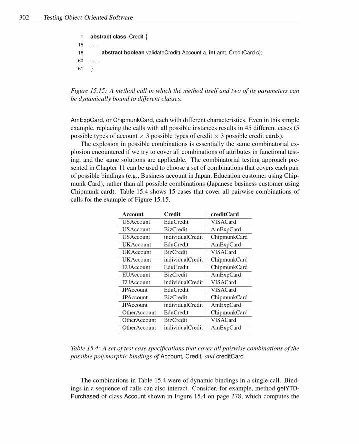
302 Testing Object-Oriented Software
1 abstract class Credit {15 . . .16 abstract boolean validateCredit( Account a, int amt, CreditCard c);60 . . .61 }
Figure 15.15: A method call in which the method itself and two of its parameters canbe dynamically bound to different classes.
AmExpCard, or ChipmunkCard, each with different characteristics. Even in this simpleexample, replacing the calls with all possible instances results in 45 different cases (5possible types of account × 3 possible types of credit × 3 possible credit cards).
The explosion in possible combinations is essentially the same combinatorial ex-plosion encountered if we try to cover all combinations of attributes in functional test-ing, and the same solutions are applicable. The combinatorial testing approach pre-sented in Chapter 11 can be used to choose a set of combinations that covers each pairof possible bindings (e.g., Business account in Japan, Education customer using Chip-munk Card), rather than all possible combinations (Japanese business customer usingChipmunk card). Table 15.4 shows 15 cases that cover all pairwise combinations ofcalls for the example of Figure 15.15.
Account Credit creditCardUSAccount EduCredit VISACardUSAccount BizCredit AmExpCardUSAccount individualCredit ChipmunkCardUKAccount EduCredit AmExpCardUKAccount BizCredit VISACardUKAccount individualCredit ChipmunkCardEUAccount EduCredit ChipmunkCardEUAccount BizCredit AmExpCardEUAccount individualCredit VISACardJPAccount EduCredit VISACardJPAccount BizCredit ChipmunkCardJPAccount individualCredit AmExpCardOtherAccount EduCredit ChipmunkCardOtherAccount BizCredit VISACardOtherAccount individualCredit AmExpCard
Table 15.4: A set of test case specifications that cover all pairwise combinations of thepossible polymorphic bindings of Account, Credit, and creditCard.
The combinations in Table 15.4 were of dynamic bindings in a single call. Bind-ings in a sequence of calls can also interact. Consider, for example, method getYTD-Purchased of class Account shown in Figure 15.4 on page 278, which computes the

Inheritance 303
total yearly purchase associated with one account to determine the applicable discount.Chipmunk offers tiered discounts to customers whose total yearly purchase reaches athreshold, considering all subsidiary accounts.
The total yearly purchase for an account is computed by method getYTDPurchased,which sums purchases by all customers using the account and all subsidiaries. Amountsare always recorded in the local currency of the account, but getYTDPurchased sumsthe purchases of subsidiaries even when they use different currencies (e.g., when someare bound to subclass USAccount and others to EUAccount). The intra- and interclasstesting techniques presented in the previous section may fail to reveal this type of fault.The problem can be addressed by selecting test cases that cover combinations of poly-morphic calls and bindings. To identify sequential combinations of bindings, we mustfirst identify individual polymorphic calls and binding sets, and then select possiblesequences.
Let us consider for simplicity only the method getYTDPurchased. This methodis called once for each customer and once for each subsidiary of the account and inboth cases can be dynamically bound to methods belonging to any of the subclasses ofAccount (UKAccount, EUAccount, and so on). At each of these calls, variable totalPur-chased is used and changed, and at the end of the method it is used twice more (to setan instance variable and to return a value from the method).
Data flow analysis may be used to identify potential interactions between possiblebindings at a point where a variable is modified and points where the same value isused. Any of the standard data flow testing criteria could be extended to consider eachpossible method binding at the point of definition and the point of use. For instance, asingle definition-use pair becomes n×m pairs if the point of definition can be boundin n ways and the point of use can be bound in m ways. If this is impractical, a weakerbut still useful alternative is to vary both bindings independently, which results in m orn pairs (whichever is greater) rather than their product. Note that this weaker criterionwould be very likely to reveal the fault in getYTDPurchased, provided the choices ofbinding at each point are really independent rather than going through the same set ofchoices in lockstep. In many cases, binding sets are not mutually independent, so theselection of combinations is limited.
15.10 Inheritance
Inheritance does not introduce new classes of faults except insofar as it is associatedwith polymorphism and dynamic binding, which we have already discussed, and ex-ception handling, which is discussed in Section 15.12. It does provide an opportunityfor optimization by reusing test cases and even test executions. Subclasses share meth-ods with ancestors. Identifying which methods do not need to be retested and whichtest cases can be reused may significantly reduce testing effort.
Methods of a subclass can be categorized as
New: if they are newly defined in the subclass — that is, they do not occur in the an-cestor. New methods include those with the same name but different parametersthan methods in ancestor classes.

304 Testing Object-Oriented Software
Method Intra funct Intra struct Inter funct Inter structLineItem 〈T SLI1,Y 〉 〈T SLI2,Y 〉 〈T SLI3,Y 〉 〈T SLI4,Y 〉validItem 〈T SvI1,N〉 〈−,−〉 〈−,−〉 〈−,−〉getUnitPrice 〈T SgUP1,N〉 〈−,−〉 〈T SgUP3,N〉 〈−,−〉getExtendedPrice 〈T SgXP1,Y 〉 〈T SgXP2,Y 〉 〈T SgXP3,Y 〉 〈T SgXP4,Y 〉getWeightGm 〈T SgWG1,N〉 〈−,−〉 〈−,−〉 〈−,−〉getHeightCm 〈T SgHC1,N〉 〈−,−〉 〈−,−〉 〈−,−〉getWidthCm 〈T SgWC1,N〉 〈−,−〉 〈−,−〉 〈−,−〉getDepthCm 〈T SgDC1,N〉 〈−,−〉 〈−,−〉 〈−,−〉Legend: 〈T SI ,B〉 refers to test set I, to be executed if B = Y .
〈−,−〉 means no applicable tests.
Table 15.5: Testing history for class LineItem
Recursive: if they are inherited from the ancestor without change — that is, they occuronly in the ancestor.
Redefined: if they are overridden in the subclass, that is, both occur in the subclass.
Abstract new: if they are newly defined and abstract in the subclass.
Abstract recursive: if they are inherited from the ancestor, where they are abstract.
Abstract redefined: if they are redefined in the subclass, and they are abstract in theancestor.
When testing a base class, one that does not specialize a previously tested class,we can summarize the testing information in a simple table that indicates the sets ofgenerated and executed test cases. Such a table is called a testing history.testing history
In general we will have four sets of test cases for a method: intraclass functional,intraclass structural, interclass functional, and interclass structural. For methods thatdo not call methods in other classes, we will have only intraclass test cases, since nointegration test focuses on such methods. For abstract methods, we will only havefunctional test cases, since we do not have the code of the method. Each set of testcases is marked with a flag that indicates whether the test set can be executed.
Table 15.5 shows a testing history for class LineItem, whose code is shown inFigure 15.16. Methods validItem, getWeightGm, getHeightCm, getWidthCm, and get-DepthCm are abstract and do not interact with external classes; thus we only haveintraclass functional test cases that cannot be directly executed. Method getUnitPriceis abstract, but from the specifications (not shown here) we can infer that it interactswith other classes; thus we have both intra- and interclass functional test cases. Boththe constructor and method getExtendedPrice are implemented and interact with otherclasses (Order and AccountType, respectively), and thus we have all four sets of testcases.
New and abstract new methods need to be tested from scratch, thus we need toderive the needed test cases and execute them. We report the testing activity in thetesting history of the new class by adding a new row and new test cases. Recursive and

Inheritance 305
1 /** One line item of a customer order (abstract). */2 public abstract class LineItem {3
4 /** The order this LineItem belongs to. */5 protected Order order;6
7 /** Constructor links item to owning order. Must call in subclasses. */8 public LineItem(Order order) { order = order; }9
10 /** Stock-keeping unit (sku) is unique key to all product databases. */11 public String sku;12
13 /** Number of identical units to be purchased. */14 public int units=1;15
16 /** Has this line item passed all validation tests? */17 public abstract boolean validItem();18
19 /** Price of a single item. */20 public abstract int getUnitPrice(AccountType accountType);21
22 /** Extended price for number of units */23 public int getExtendedPrice(AccountType accountType)24 { return units * this.getUnitPrice(accountType); }25
26 // Dimensions for packing and shipping (required of all top-level items)27 /** Weight in grams */28 public abstract int getWeightGm();29 /** Height in centimeters */30 public abstract int getHeightCm();31 /** Width in Centimeters. */32 public abstract int getWidthCm();33 /** Depth in Centimeters */34 public abstract int getDepthCm();35 }
Figure 15.16: Part of a Java implementation of the abstract class LineItem.

306 Testing Object-Oriented Software
Method Intra funct Intra struct Inter funct Inter structLineItem 〈T SLI1,N〉 〈T SLI2,N〉 〈T SLI3,N〉 〈T SLI4,N〉validItem 〈T SvI1,N〉 〈−,−〉 〈−,−〉 〈−,−〉getUnitPrice 〈T SgUP1,Y 〉 〈T S′gUP2,Y 〉 〈T SgUP3,Y 〉 〈T S′gUP4,Y 〉getExtendedPrice 〈T SgXP1,N〉 〈T SgXP2,N〉 〈T SgXP3,N〉 〈T SgXP4,N〉getWeightGm 〈T SgWG1,N〉 〈−,−〉 〈−,−〉 〈−,−〉getHeightCm 〈T SgHC1,N〉 〈−,−〉 〈−,−〉 〈−,−〉getWidthCm 〈T SgWC1,N〉 〈−,−〉 〈−,−〉 〈−,−〉getDepthCm 〈T SgDC1,N〉 〈−,−〉 〈−,−〉 〈−,−〉CompositeItem 〈T S′CM1,Y 〉 〈T S′CM2,Y 〉 〈T S′CM3,Y 〉 〈T S′CM4,Y 〉
Table 15.6: Testing history for class CompositeItem. New test sets are marked with aprime.
abstract recursive methods do not need to be retested. Thus the old test sets are copiedinto the new table and marked as not-to-be-executed. Redefined and abstract redefinedmethods must be retested, so we add new test cases and mark them to be executed.
Table 15.6 shows the testing history for class CompositeItem that specializes classLineItem. The code of class CompositeItem is shown in Figure 15.17. Class Compos-iteItem adds a constructor, and thus we add a line to the testing history that indicates thefour sets of test cases to be added and executed. It redefines method getUnitPrice, whichwas virtual in class LineItem: the functional test cases derived for class LineItem arethus executed, and new structural test cases are added. All other classes are inherited,and thus the testing history reports all test cases and marks them as not-to-be-executed.
The testing history approach reduces the number of tests to be executed, but re-quires extra effort of keeping track of testing activities. Effort is repaid mainly when itis possible to avoid designing new test cases, but when the cost of executing test casesis high (e.g., because the test requires interaction with an external device or a human)the savings in test execution cost can also be significant. If the cost of executing testcases is negligible, it may be cheaper to simply retest all classes regardless of the testsexecuted on the ancestors.
15.11 Genericity
Generics, also known as parameterized types or (in C++) as templates, are an im-portant tool for building reusable components and libraries. A generic class (say,linked lists) is designed to be instantiated with many different parameter types (e.g.,LinkedList<String> and LinkedList<Integer>). We can test only instantiations, not thegeneric class itself, and we may not know in advance all the different ways a genericclass might be instantiated.
A generic class is typically designed to behave consistently over some set of per-mitted parameter types. Therefore the testing (and analysis) job can be broken intotwo parts: showing that some instantiation is correct and showing that all permittedinstantiations behave identically.

Genericity 307
1 package Orders;2 import Accounts.AccountType;3 import Prices.Pricelist;4 import java.util.*;5
6 /**7 * A composite line item includes a ”wrapper” item for the whole8 * bundle and a set of zero or more component items.9 */
10 public abstract class CompositeItem extends LineItem {11
12 /**13 * A composite item has some unifying name and base price14 * (which might be zero) and has zero or more additional parts,15 * which are themselves line items.16 */17 private Vector parts = new Vector();18
19 /**20 * Constructor from LineItem, links to an encompassing Order.21 */22 public CompositeItem(Order order) {23 super( order);24 }25
26 public int getUnitPrice(AccountType accountType) {27 Pricelist prices = new Pricelist();28 int price = prices.getPrice(sku, accountType);29 for (Enumeration e = parts.elements(); e.hasMoreElements(); )30 {31 LineItem i = (LineItem) e.nextElement();32 price += i.getUnitPrice(accountType);33 }34 return price;35 }36 }37
Figure 15.17: Part of a Java implementation of class CompositeItem.

308 Testing Object-Oriented Software
Testing a single instantiation raises no particular problems, provided we have sourcecode for both the generic class and the parameter class. Roughly speaking, we can de-sign test cases as if the parameter were copied textually into the body of the genericclass.
Consider first the case of a generic class that does not make method calls on, noraccess fields of, its parameters. Ascertaining this property is best done by inspectingthe source code, not by testing it. If we can nonetheless conjecture some ways inwhich the generic and its parameter might interact (e.g., if the generic makes use ofsome service that a parameter type might also make use of, directly or indirectly), thenwe should design test cases aimed specifically at detecting such interaction.
Gaining confidence in an unknowable set of potential instantiations becomes moredifficult when the generic class does interact with the parameter class. For example,Java (since version 1.5) has permitted a declaration like this:
class PriorityQueue<Elem implements Comparable> { . . .}
The generic PriorityQueue class will be able to make calls on the methods of in-terface Comparable. Now the behavior of PriorityQueue<E> is not independent of E,but it should be dependent only in certain very circumscribed ways, and in particular itshould behave correctly whenever E obeys the requirements of the contract implied byComparable.
The contract imposed on permitted parameters is a kind of specification, and spec-ification-based (functional) test selection techniques are an appropriate way to selectrepresentative instantiations of the generic class. For example, if we read the inter-face specification for java.lang.Comparable, we learn that most but not all classes thatimplement Comparable also satisfy the rule
(x.compareTo(y) == 0) == (x.equals(y))
Explicit mention of this condition strongly suggests that test cases should include in-stantiations with classes that do obey this rule (class String, for example) and othersthat do not (e.g., class BigDecimal with two BigDecimal values 4.0 and 4.00).
15.12 Exceptions
Programs in modern object-oriented languages use exceptions to separate handlingof error cases from the primary program logic, thereby simplifying normal controlflow. Exceptions also greatly reduce a common class of faults in languages withoutexception-handling constructs. One of the most common faults in C programs, for ex-ample, is neglecting to check for the error indications returned by a C function. In alanguage like Java, an exception is certain to interrupt normal control flow.
The price of separating exception handling from the primary control flow logic isintroduction of implicit control flows. The point at which an exception is caught andhandled may be far from the point at which it is thrown. Moreover, the association ofexceptions with handlers is dynamic. In most object-oriented languages and procedural

Exceptions 309
languages that provide exception handling, an exception propagates up the stack ofcalling methods until it reaches a matching handler.
Since exceptions introduce a kind of control flow, one might expect that it could betreated like other control flow in constructing program models and deriving test cases.However, treating every possible exception this way would create an unwieldy controlflow graph accounting for potential exceptions at every array subscript reference, everymemory allocation, every cast, and so on, and these would be multiplied by matchingthem to every handler that could appear immediately above them on the call stack.Worse, many of these potential exceptions are actually impossible, so the burden wouldnot be just in designing test cases for each of them but in deciding which can actuallyoccur. It is more practical to consider exceptions separately from normal control flowin test design.
We can dismiss from consideration exceptions triggered by program errors signaledby the underlying system (subscript errors, bad casts, etc.), since exercising these ex-ceptions adds nothing to other efforts to prevent or find the errors themselves. If amethod A throws an exception that indicates a programming error, we can take almostthe same approach. However, if there are exception handlers for these program errorexceptions, such as we may find in fault-tolerant programs or in libraries that attemptto maintain data consistency despite errors in client code, then it is necessary to testthe error recovery code (usually by executing it together with a stub class with theprogramming error). This is different and much less involved than testing the errorrecovery code coupled with every potential point at which the error might be present inactual code.
Exceptions that indicate abnormal cases but not necessarily program errors (e.g.,exhaustion of memory or premature end-of-file) require special treatment. If the han-dler for these is local (e.g., a Java try block with an exception handler around a groupof file operations), then the exception handler itself requires testing. Whether to testeach individual point where exceptions bound to the same handler might be raised (e.g.,each individual file operation within the same try block) is a matter of judgment.
The remaining exceptions are those that are allowed to propagate beyond the localcontext in which they are thrown. For example, suppose method A makes a call tomethod B, within a Java try block with an exception handler for exceptions of class E.Suppose B has no exception handler for E and makes a call to method C, which throwsE. Now the exception will propagate up the chain of method calls until it reaches thehandler in A. There could be many such chains, which depend in part on overridinginherited methods, and it is difficult (sometimes even impossible) to determine all andonly the possible pairings of points where an exception is thrown with handlers in othermethods.
Since testing all chains through which exceptions can propagate is impractical, itis best to make it unnecessary. A reasonable design rule to enforce is that, if a methodpropagates an exception without catching it, the method call should have no other ef-fect. If it is not possible to ensure that method execution interrupted by an exceptionhas no effect, then an exception handler should be present (even if it propagates thesame exception by throwing it again). Then, it should suffice to design test cases toexercise each point at which an exception is explicitly thrown by application code, andeach handler in application code, but not necessarily all their combinations.
310 Testing Object-Oriented Software
Open Research Issues
Many problems involved in test and analysis of object-oriented systems are still open.Most results about functional testing refer to a subset of UML and to algebraic specifi-cations. Additional work is needed to complete the available methods to cope with allaspects of object-oriented systems and different specification approaches.
The few techniques for structural testing disclose a wide set of problems that needadditional investigation. We need additional experimental data about the effectivenessof the available techniques and better ways to cope with interclass testing.
Test and analysis problems of many features that characterize object-oriented sys-tems, such as exceptions, polymorphism, dynamic binding, and inheritance, have beeninvestigated only partially and need additional work. Despite a good deal of experiencewith object-oriented design, we still have little information about common faults, andwe lack fault taxonomies.
Further Reading
Many recent books on software testing and software engineering address object-orientedsoftware to at least some degree. The most complete book-length account of currentmethods is Binder’s Testing Object Oriented Systems [Bin00].
Structural state-based testing is discussed in detail by Buy, Orso, and Pezze [BOP00].The data flow approach to testing software with polymorphism and dynamic bindingwas initially proposed by Orso [Ors98]. Harrold, McGregor, and Fitzpatrick [HMF92]provide a detailed discussion of the use of testing histories for selecting test cases forsubclasses.
Thevenod-Fosse and Waeselynck describe statistical testing using statechart speci-fications [TFW93]. An excellent paper by Doong and Frankl [DF94] introduces equiv-alent scenarios. Although Doong and Frankl discuss their application with algebraicspecifications (which are not much used in practice), the value of the approach doesnot hinge on that detail.
Related Topics
Basic functional and structural testing strategies are treated briefly here, and readerswho have not already read Chapters 10, 11, and 12 will find there a more thorough pre-sentation of the rationale and basic techniques for those approaches. Chapters 13 and14 likewise present the basic data flow and model-based testing approaches in moredetail. As integration testing progresses beyond small clusters of classes to major sub-systems and components, the interclass testing techniques described in this chapter willbecome less relevant, and component testing techniques presented in Chapter 21 moreimportant. The system and acceptance testing techniques described in Chapter 22 areas appropriate to object-oriented software as they are to mixed and purely proceduralsoftware systems.

Exceptions 311
Exercises
15.1. The set of test cases given in Table 15.1 is not the smallest test suite that satis-fies the transition coverage criterion for the finite state machine (FSM) of Fig-ure 15.7.
(a) Derive a smaller set of test cases that satisfy the transition coverage crite-rion for the FSM.
(b) Compare the two sets of test cases. What are the advantages of each?
(c) Derive a suite of test cases that satisfies the simple transition coverage cri-terion but does not satisfy the transition coverage criterion.
15.2. The test cases given in Table 15.1 assume that transitions not given explicitlyare “don’t care,” and thus we do not exercise them. Modify the test suite, firstassuming that omitted transitions are “error” transitions. Next, modify the sametest suite, but instead assuming that the omitted transitions are “self” transitions.Are the two modified test suites different? Why or why not?
15.3. Generate at least one equivalent and one nonequivalent scenario for at least oneof the test cases TCA, . . . ,TCE of Table 15.1.
15.4. A canonical representation is a unique representation of a set of equivalent ob-jects. For example, {a,a,c,b}, {c,b,a}, and {a,b,c} are all representations ofthe same mathematical set object. If we choose a lexicographically sorted rep-resentation without duplicates as a canonical representation, then we will use{a,b,c} as the unique way of writing that set.
Imagine we are using the equivalent scenarios approach to test a hash table class.Why might we want a toString method that returns a canonical representation ofthe table? Give an example of a test case in which you might use it.

312 Testing Object-Oriented Software

Chapter 16
Fault-Based Testing
A model of potential program faults is a valuable source of information for evaluat-ing and designing test suites. Some fault knowledge is commonly used in functionaland structural testing, for example when identifying singleton and error values for pa-rameter characteristics in category-partition testing or when populating catalogs witherroneous values, but a fault model can also be used more directly. Fault-based testinguses a fault model directly to hypothesize potential faults in a program under test, aswell as to create or evaluate test suites based on its efficacy in detecting those hypo-thetical faults.
Required Background
• Chapter 9The introduction to test case selection and adequacy sets the context for thischapter. Though not strictly required, it is helpful in understanding how thetechniques described in this chapter should be applied.
• Chapter 12Some basic knowledge of structural testing criteria is required to understand thecomparison of fault-based with structural testing criteria.
16.1 Overview
Engineers study failures to understand how to prevent similar failures in the future.For example, failure of the Tacoma Narrows Bridge in 1940 led to new understandingof oscillation in high wind and to the introduction of analyses to predict and preventsuch destructive oscillation in subsequent bridge design. The causes of an airline crashare likewise extensively studied, and when traced to a structural failure they frequentlyresult in a directive to apply diagnostic tests to all aircraft considered potentially vul-nerable to similar failures.
313

314 Fault-Based Testing
Experience with common software faults sometimes leads to improvements in de-sign methods and programming languages. For example, the main purpose of auto-matic memory management in Java is not to spare the programmer the trouble ofreleasing unused memory, but to prevent the programmer from making the kind ofmemory management errors (dangling pointers, redundant deallocations, and memoryleaks) that frequently occur in C and C++ programs. Automatic array bounds checkingcannot prevent a programmer from using an index expression outside array bounds,but can make it much less likely that the fault escapes detection in testing, as well aslimiting the damage incurred if it does lead to operational failure (eliminating, in par-ticular, the buffer overflow attack as a means of subverting privileged programs). Typechecking reliably detects many other faults during program translation.
Of course, not all programmer errors fall into classes that can be prevented or stat-ically detected using better programming languages. Some faults must be detectedthrough testing, and there too we can use knowledge about common faults to be moreeffective.
The basic concept of fault-based testing is to select test cases that would distinguishthe program under test from alternative programs that contain hypothetical faults. Thisis usually approached by modifying the program under test to actually produce thehypothetical faulty programs. Fault seeding can be used to evaluate the thoroughnessof a test suite (that is, as an element of a test adequacy criterion), or for selecting testcases to augment a test suite, or to estimate the number of faults in a program.
16.2 Assumptions in Fault-Based Testing
The effectiveness of fault-based testing depends on the quality of the fault model andon some basic assumptions about the relation of the seeded faults to faults that mightactually be present. In practice, the seeded faults are small syntactic changes, likereplacing one variable reference by another in an expression, or changing a comparisonfrom < to <=. We may hypothesize that these are representative of faults actuallypresent in the program.
Put another way, if the program under test has an actual fault, we may hypothe-size that it differs from another, corrected program by only a small textual change. Ifso, then we need merely distinguish the program from all such small variants (by se-lecting test cases for which either the original or the variant program fails) to ensure∆ competent
programmerhypothesis
detection of all such faults. This is known as the competent programmer hypothesis, anassumption that the program under test is “close to” (in the sense of textual difference)a correct program.
Some program faults are indeed simple typographical errors, and others that in-volve deeper errors of logic may nonetheless be manifest in simple textual differences.Sometimes, though, an error of logic will result in much more complex differences inprogram text. This may not invalidate fault-based testing with a simpler fault model,provided test cases sufficient for detecting the simpler faults are sufficient also for de-tecting the more complex fault. This is known as the coupling effect.∆ coupling effect
hypothesis The coupling effect hypothesis may seem odd, but can be justified by appeal to amore plausible hypothesis about interaction of faults. A complex change is equivalent

Mutation Analysis 315
Fault-Based Testing: TerminologyOriginal program: The program unit (e.g., C function or Java class) to be tested.
Program location: A region in the source code. The precise definition is defined rel-ative to the syntax of a particular programming language. Typical locations arestatements, arithmetic and Boolean expressions, and procedure calls.
Alternate expression: Source code text that can be legally substituted for the text at aprogram location. A substitution is legal if the resulting program is syntacticallycorrect (i.e., it compiles without errors).
Alternate program: A program obtained from the original program by substitutingan alternate expression for the text at some program location.
Distinct behavior of an alternate program R for a test t: The behavior of an alter-nate program R is distinct from the behavior of the original program P for a testt, if R and P produce a different result for t, or if the output of R is not definedfor t.
Distinguished set of alternate programs for a test suite T : A set of alternate pro-grams are distinct if each alternate program in the set can be distinguished fromthe original program by at least one test in T .
to several smaller changes in program text. If the effect of one of these small changesis not masked by the effect of others, then a test case that differentiates a variant basedon a single change may also serve to detect the more complex error.
Fault-based testing can guarantee fault detection only if the competent programmerhypothesis and the coupling effect hypothesis hold. But guarantees are more than weexpect from other approaches to designing or evaluating test suites, including the struc-tural and functional test adequacy criteria discussed in earlier chapters. Fault-basedtesting techniques can be useful even if we decline to take the leap of faith requiredto fully accept their underlying assumptions. What is essential is to recognize thedependence of these techniques, and any inferences about software quality based onfault-based testing, on the quality of the fault model. This also implies that developingbetter fault models, based on hard data about real faults rather than guesses, is a goodinvestment of effort.
16.3 Mutation Analysis
Mutation analysis is the most common form of software fault-based testing. A faultmodel is used to produce hypothetical faulty programs by creating variants of the pro-gram under test. Variants are created by “seeding” faults, that is, by making a smallchange to the program under test following a pattern in the fault model. The patterns ∆ mutation
operatorfor changing program text are called mutation operators, and each variant program is∆ mutantcalled a mutant.

316 Fault-Based Testing
Mutation Analysis: TerminologyOriginal program under test: The program or procedure (function) to be tested.
Mutant: A program that differs from the original program for one syntactic element(e.g., a statement, a condition, a variable, a label).
Distinguished mutant: A mutant that can be distinguished for the original programby executing at least one test case.
Equivalent mutant: A mutant that cannot be distinguished from the original program.
Mutation operator: A rule for producing a mutant program by syntactically modify-ing the original program.
Mutants should be plausible as faulty programs. Mutant programs that are rejectedby a compiler, or that fail almost all tests, are not good models of the faults we seek touncover with systematic testing.
We say a mutant is valid if it is syntactically correct. A mutant obtained from∆ valid mutant
the program of Figure 16.1 by substituting while for switch in the statement at line 13would not be valid, since it would result in a compile-time error. We say a mutant isuseful if, in addition to being valid, its behavior differs from the behavior of the original∆ useful mutant
program for no more than a small subset of program test cases. A mutant obtained bysubstituting 0 for 1000 in the statement at line 4 would be valid, but not useful, sincethe mutant would be distinguished from the program under test by all inputs and thuswould not give any useful information on the effectiveness of a test suite. Definingmutation operators that produce valid and useful mutations is a nontrivial task.
Since mutants must be valid, mutation operators are syntactic patterns defined rela-tive to particular programming languages. Figure 16.2 shows some mutation operatorsfor the C language. Constraints are associated with mutation operators to guide selec-tion of test cases likely to distinguish mutants from the original program. For example,the mutation operator svr (scalar variable replacement) can be applied only to variablesof compatible type (to be valid), and a test case that distinguishes the mutant from theoriginal program must execute the modified statement in a state in which the originalvariable and its substitute have different values.
Many of the mutants of Figure 16.2 can be applied equally well to other procedurallanguages, but in general a mutation operator that produces valid and useful mutantsfor a given language may not apply to a different language or may produce invalid oruseless mutants for another language. For example, a mutation operator that removesthe “friend” keyword from the declaration of a C++ class would not be applicable toJava, which does not include friend classes.

Mutation Analysis 317
1
2 /** Convert each line from standard input */3 void transduce() {4 #define BUFLEN 10005 char buf[BUFLEN]; /* Accumulate line into this buffer */6 int pos = 0; /* Index for next character in buffer */7
8 char inChar; /* Next character from input */9
10 int atCR = 0; /* 0=”within line”, 1=”optional DOS LF” */11
12 while ((inChar = getchar()) != EOF ) {13 switch (inChar) {14 case LF:15 if (atCR) { /* Optional DOS LF */16 atCR = 0;17 } else { /* Encountered CR within line */18 emit(buf, pos);19 pos = 0;20 }21 break;22 case CR:23 emit(buf, pos);24 pos = 0;25 atCR = 1;26 break;27 default:28 if (pos >= BUFLEN-2) fail("Buffer overflow");29 buf[pos++] = inChar;30 } /* switch */31 }32 if (pos > 0) {33 emit(buf, pos);34 }35 }
Figure 16.1: Program transduce converts line endings among Unix, DOS, and Mac-intosh conventions. The main procedure, which selects the output line end convention,and the output procedure emit are not shown.

318 Fault-Based Testing
ID Operator Description Constraint
Operand Modificationscrp constant for constant replacement replace constant C1 with constant C2 C1 6= C2scr scalar for constant replacement replace constant C with scalar variable X C 6= Xacr array for constant replacement replace constant C with array reference
A[I]C 6= A[I]
scr struct for constant replacement replace constant C with struct field S C 6= Ssvr scalar variable replacement replace scalar variable X with a scalar
variable YX 6= Y
csr constant for scalar variable replacement replace scalar variable X with a constantC
X 6= C
asr array for scalar variable replacement replace scalar variable X with an arrayreference A[I]
X 6= A[I]
ssr struct for scalar replacement replace scalar variable X with struct fieldS
X 6= S
vie scalar variable initialization elimination remove initialization of a scalar variablecar constant for array replacement replace array reference A[I] with constant
CA[I] 6= C
sar scalar for array replacement replace array reference A[I] with scalarvariable X
A[I] 6= X
cnr comparable array replacement replace array reference with a compara-ble array reference
sar struct for array reference replacement replace array reference A[I] with a structfield S
A[I] 6= S
Expression Modificationsabs absolute value insertion replace e by abs(e) e < 0aor arithmetic operator replacement replace arithmetic operator ψ with arith-
metic operator φ
e1ψe2 6= e1φe2
lcr logical connector replacement replace logical connector ψ with logicalconnector φ
e1ψe2 6= e1φe2
ror relational operator replacement replace relational operator ψ with rela-tional operator φ
e1ψe2 6= e1φe2
uoi unary operator insertion insert unary operatorcpr constant for predicate replacement replace predicate with a constant value
Statement Modificationssdl statement deletion delete a statementsca switch case replacement replace the label of one case with anotherses end block shift move } one statement earlier and later
Figure 16.2: A sample set of mutation operators for the C language, with associated constraints to selecttest cases that distinguish generated mutants from the original program.

Fault-Based Adequacy Criteria 319
16.4 Fault-Based Adequacy Criteria
Given a program and a test suite T , mutation analysis consists of the following steps:
Select mutation operators: If we are interested in specific classes of faults, we mayselect a set of mutation operators relevant to those faults.
Generate mutants: Mutants are generated mechanically by applying mutation opera-tors to the original program.
Distinguish mutants: Execute the original program and each generated mutant withthe test cases in T . A mutant is killed when it can be distinguished from theoriginal program.
Figure 16.3 shows a sample of mutants for program Transduce, obtained by apply-ing the mutant operators in Figure 16.2. Test suite T S
T S = {1U,1D,2U,2D,2M,End,Long}
kills M j, which can be distinguished from the original program by test cases 1D, 2U ,2D, and 2M. Mutants Mi, Mk, and Ml are not distinguished from the original programby any test in T S. We say that mutants not killed by a test suite are live. live mutants
A mutant can remain live for two reasons:
• The mutant can be distinguished from the original program, but the test suiteT does not contain a test case that distinguishes them (i.e., the test suite is notadequate with respect to the mutant).
• The mutant cannot be distinguished from the original program by any test case(i.e., the mutant is equivalent to the original program).
Given a set of mutants SM and a test suite T , the fraction of nonequivalent mutantskilled by T measures the adequacy of T with respect to SM. Unfortunately, the problemof identifying equivalent mutants is undecidable in general, and we could err either byclaiming that a mutant is equivalent to the program under test when it is not or bycounting some equivalent mutants among the remaining live mutants.
The adequacy of the test suite T S evaluated with respect to the four mutants ofFigure 16.3 is 25%. However, we can easily observe that mutant Mi is equivalent tothe original program (i.e., no input would distinguish it). Conversely, mutants Mk andMl seem to be nonequivalent to the original program: There should be at least one testcase that distinguishes each of them from the original program. Thus the adequacy ofT S, measured after eliminating the equivalent mutant Mi, is 33%.
Mutant Ml is killed by test case Mixed, which represents the unusual case of aninput file containing both DOS- and Unix-terminated lines. We would expect thatMixed would also kill Mk, but this does not actually happen: Both Mk and the originalprogram produce the same result for Mixed. This happens because both the mutant andthe original program fail in the same way.1 The use of a simple oracle for checking
1The program was in regular use by one of the authors and was believed to be correct. Discovery of thefault came as a surprise while using it as an example for this chapter.

320 Fault-Based Testing
Mutation Analysis vs. Structural TestingFor typical sets of syntactic mutants, a mutation-adequate test suite will also be
adequate with respect to simple structural criteria such as statement or branch coverage.Mutation adequacy can simulate and subsume a structural coverage criterion if the setof mutants can be killed only by satisfying the corresponding test coverage obligations.
Statement coverage can be simulated by applying the mutation operator sdl (state-ment deletion) to each statement of a program. To kill a mutant whose only differencefrom the program under test is the absence of statement S requires executing the mu-tant and the program under test with a test case that executes S in the original program.Thus to kill all mutants generated by applying the operator sdl to statements of theprogram under test, we need a test suite that causes the execution of each statement inthe original program.
Branch coverage can be simulated by applying the operator cpr (constant for pred-icate replacement) to all predicates of the program under test with constants True andFalse . To kill a mutant that differs from the program under test for a predicate P setto the constant value False , we need to execute the mutant and the program under testwith a test case that causes the execution of the True branch of P. To kill a mutant thatdiffers from the program under test for a predicate P set to the constant value True , weneed to execute the mutant and the program under test with a test case that causes theexecution of the False branch of P.
A test suite that satisfies a structural test adequacy criterion may or may not killall the corresponding mutants. For example, a test suite that satisfies the statementcoverage adequacy criterion might not kill an sdl mutant if the value computed at thestatement does not affect the behavior of the program on some possible executions.
Original/ID Operator line Mutant 1U 1D 2U 2D 2M End Long MixedMi ror 28 (pos >= BUFLEN−2)
(pos == BUFLEN−2)- - - - - - - -
M j ror 32 (pos > 0)(pos >= 0)
- x x x x - - -
Mk sdl 16 atCR = 0nothing
- - - - - - - -
Ml ssr 16 atCR = 0pos = 0
- - - - - - - x
Test case Description1U One line, Unix line-end1D One line, DOS line-end2U Two lines, Unix line-end2D Two lines, DOS line-end
Test case Description2M Two lines, Mac line-endEnd Last line not terminated with line-end sequenceLong Very long line (greater than buffer length)Mixed Mix of DOS and Unix line ends in the same file
Figure 16.3: A sample set of mutants for program Transduce generated with mutation operators fromFigure 16.2. x indicates the mutant is killed by the test case in the column head.

Variations on Mutation Analysis 321
the correctness of the outputs (e.g., checking each output against an expected output)would reveal the fault. The test suite T S2 obtained by adding test case Mixed to T Swould be 100% adequate (relative to this set of mutants) after removing the fault.
16.5 Variations on Mutation Analysis
The mutation analysis process described in the preceding sections, which kills mutantsbased on the outputs produced by execution of test cases, is known as strong mutation.It can generate a number of mutants quadratic in the size of the program. Each mutantmust be compiled and executed with each test case until it is killed. The time and spacerequired for compiling all mutants and for executing all test cases for each mutant maybe impractical.
The computational effort required for mutation analysis can be reduced by decreas-ing the number of mutants generated and the number of test cases to be executed. Weakmutation analysis decreases the number of tests to be executed by killing mutants whenthey produce a different intermediate state, rather than waiting for a difference in thefinal result or observable program behavior. weak mutation
analysisWith weak mutation, a single program can be seeded with many faults. A “meta-mutant” program is divided into segments containing original and mutated source code,with a mechanism to select which segments to execute. Two copies of the meta-mutantare executed in tandem, one with only original program code selected and the otherwith a set of live mutants selected. Execution is paused after each segment to comparethe program state of the two versions. If the state is equivalent, execution resumes withthe next segment of original and mutated code. If the state differs, the mutant is markedas dead, and execution of original and mutated code is restarted with a new selectionof live mutants.
Weak mutation testing does not decrease the number of program mutants that mustbe considered, but it does decrease the number of test executions and compilations.This performance benefit has a cost in accuracy: Weak mutation analysis may “kill”a mutant even if the changed intermediate state would not have an effect on the finaloutput or observable behavior of the program.
Like structural test adequacy criteria, mutation analysis can be used either to judgethe thoroughness of a test suite or to guide selection of additional test cases. If one isdesigning test cases to kill particular mutants, then it may be important to have a com-plete set of mutants generated by a set of mutation operators. If, on the other hand, thegoal is a statistical estimate of the extent to which a test suite distinguishes programswith seeded faults from the original program, then only a much smaller statistical sam-ple of mutants is required. Aside from its limitation to assessment rather than creation statistical
mutation analysisof test suites, the main limitation of statistical mutation analysis is that partial coverageis meaningful only to the extent that the generated mutants are a valid statistical modelof occurrence frequencies of actual faults. To avoid reliance on this implausible as-sumption, the target coverage should be 100% of the sample; statistical sampling maykeep the sample small enough to permit careful examination of equivalent mutants.

322 Fault-Based Testing
Estimating Population Sizes
Counting fish Lake Winnemunchie is inhabited by two kinds of fish, a native troutand an introduced species of chub. The Fish and Wildlife Service wishes to estimatethe populations to evaluate their efforts to eradicate the chub without harming the pop-ulation of native trout.
The population of chub can be estimated statistically as follows. 1000 chub arenetted, their dorsal fins are marked by attaching a tag, then they are released back intothe lake. Over the next weeks, fishermen are asked to report the number of tagged anduntagged chub caught. If 50 tagged chub and 300 untagged chub are caught, we cancalculate
1000untagged chub population
=50300
and thus there are about 6000 untagged chub remaining in the lake.It may be tempting to also ask fishermen to report the number of trout caught and
to perform a similar calculation to estimate the ratio between chub and trout. However,this is valid only if trout and chub are equally easy to catch, or if one can adjust theratio using a known model of trout and chub vulnerability to fishing.
Counting residual faults A similar procedure can be used to estimate the number offaults in a program: Seed a given number S of faults in the program. Test the programwith some test suite and count the number of revealed faults. Measure the number ofseeded faults detected, DS, and also the number of natural faults DN detected. Esti-mate the total number of faults remaining in the program, assuming the test suite is aseffective at finding natural faults as it is at finding seeded faults, using the formula
Stotal natural faults
=DS
DN
If we estimate the number of faults remaining in a program by determining theproportion of seeded faults detected, we must be wary of the pitfall of estimating troutpopulation by counting chub. The seeded faults are chub, the real faults are trout,and we must either have good reason for believing the seeded faults are no easier todetect than real remaining faults, or else make adequate allowances for uncertainty.The difference is that we cannot avoid the problem by repeating the process with trout— once a fault has been detected, our knowledge of its presence cannot be erased. Wedepend, therefore, on a very good fault model, so that the chub are as representativeas possible of trout. Of course, if we use special bait for chub, or design test cases todetect particular seeded faults, then statistical estimation of the total population of fishor errors cannot be justified.

Variations on Mutation Analysis 323
Hardware Fault-based TestingFault-based testing is widely used for semiconductor and hardware system valida-
tion and evaluation both for evaluating the quality of test suites and for evaluating faulttolerance.
Semiconductor testing has conventionally been aimed at detecting random errors infabrication, rather than design faults. Relatively simple fault models have been devel-oped for testing semiconductor memory devices, the prototypical faults being “stuck-at-0” and “stuck-at-1” (a gate, cell, or pin that produces the same logical value re-gardless of inputs). A number of more complex fault models have been developed forparticular kinds of semiconductor devices (e.g., failures of simultaneous access in dual-port memories). A test vector (analogous to a test suite for software) can be judged bythe number of hypothetical faults it can detect, as a fraction of all possible faults underthe model.
Fabrication of a semiconductor device, or assembly of a hardware system, is moreanalogous to copying disk images than to programming. The closest analog of soft-ware is not the hardware device itself, but its design — in fact, a high-level design ofa semiconductor device is essentially a program in a language that is compiled intosilicon. Test and analysis of logic device designs faces the same problems as test andanalysis of software, including the challenge of devising fault models. Hardware de-sign verification also faces the added problem that it is much more expensive to replacefaulty devices that have been delivered to customers than to deliver software patches.
In evaluation of fault tolerance in hardware, the usual approach is to modify thestate or behavior rather than the system under test. Due to a difference in terminol-ogy between hardware and software testing, the corruption of state or modificationof behavior is called a “fault,” and artificially introducing it is called “fault injection.”Pin-level fault injection consists of forcing a stuck-at-0, a stuck-at-1, or an intermediatevoltage level (a level that is neither a logical 0 nor a logical 1) on a pin of a semicon-ductor device. Heavy ion radiation is also used to inject random faults in a runningsystem. A third approach, growing in importance as hardware complexity increases,uses software to modify the state of a running system or to simulate faults in a runningsimulation of hardware logic design.
Fault seeding can be used statistically in another way: To estimate the number offaults remaining in a program. Usually we know only the number of faults that havebeen detected, and not the number that remains. However, again to the extent that thefault model is a valid statistical model of actual fault occurrence, we can estimate thatthe ratio of actual faults found to those still remaining should be similar to the ratio ofseeded faults found to those still remaining.
Once again, the necessary assumptions are troubling, and one would be unwise toplace too much confidence in an estimate of remaining faults. Nonetheless, a predictionwith known weaknesses is better than a seat-of-the-pants guess, and a set of estimatesderived in different ways is probably the best one can hope for.
While the focus of this chapter is on fault-based testing of software, related tech-

324 Fault-Based Testing
niques can be applied to whole systems (hardware and software together) to evaluatefault tolerance. Some aspects of fault-based testing of hardware are discussed in thesidebar on page 323.
Open Research Issues
Fault-based testing has yet to be widely applied in software development, although itis an important research tool for evaluating other test selection techniques. Its limitedimpact on software practice so far can be blamed perhaps partly on computationalexpense and partly on the lack of adequate support by industrial strength tools.
One promising direction in fault-based testing is development of fault models forparticular classes of faults. These could result in more sharply focused fault-basedtechniques, and also partly address concerns about the extent to which the fault modelsconventionally used in mutation testing are representative of real faults. Two areasin which researchers have attempted to develop focused models, expressed as sets ofmutation operators, are component interfaces and concurrency constructs.
Particularly important is development of fault models based on actual, observedfaults in software. These are almost certainly dependent on application domain andperhaps to some extent also vary across software development organizations, but toolittle empirical evidence is available on the degree of variability.
Further Reading
Software testing using fault seeding was developed by Hamlet [Ham77] and indepen-dently by DeMillo, Lipton, and Sayward [DLS78]. Underlying theories for fault-basedtesting, and in particular on the conditions under which a test case can distinguish faultyand correct versions of a program, were developed by Morell [Mor90] and extendedby Thompson, Richardson, and Clarke [TRC93]. Statistical mutation using a Bayesianapproach to grow the sample until sufficient evidence has been collected has been de-scribed by Sahinoglu and Spafford [SS90]. Weak mutation was proposed by Howden[How82]. The sample mutation operators used in this chapter are adapted from theMothra software testing environment [DGK+88].
Exercises
16.1. Consider the C function in Figure 16.4, used to determine whether a misspelledword differs from a dictionary word by at most one character, which may be adeletion, an insertion, or a substitution (e.g., “text” is edit distance 1 from “test”by a substitution, and edit distance 1 from “tests” by deletion of “s”).
Suppose we seed a fault in line 27, replacing s1 +1 by s1 + 0. Is there a test casethat will kill this mutant using weak mutation, but not using strong mutation?Display such a test case if there is one, or explain why there is none.
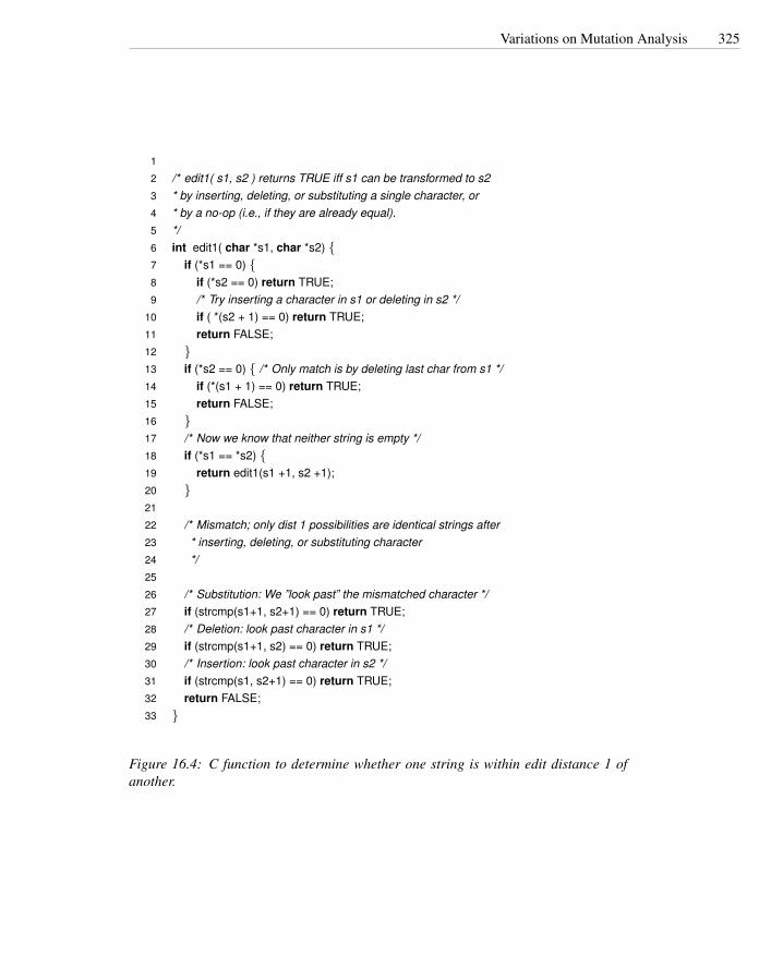
Variations on Mutation Analysis 325
1
2 /* edit1( s1, s2 ) returns TRUE iff s1 can be transformed to s23 * by inserting, deleting, or substituting a single character, or4 * by a no-op (i.e., if they are already equal).5 */6 int edit1( char *s1, char *s2) {7 if (*s1 == 0) {8 if (*s2 == 0) return TRUE;9 /* Try inserting a character in s1 or deleting in s2 */
10 if ( *(s2 + 1) == 0) return TRUE;11 return FALSE;12 }13 if (*s2 == 0) { /* Only match is by deleting last char from s1 */14 if (*(s1 + 1) == 0) return TRUE;15 return FALSE;16 }17 /* Now we know that neither string is empty */18 if (*s1 == *s2) {19 return edit1(s1 +1, s2 +1);20 }21
22 /* Mismatch; only dist 1 possibilities are identical strings after23 * inserting, deleting, or substituting character24 */25
26 /* Substitution: We ”look past” the mismatched character */27 if (strcmp(s1+1, s2+1) == 0) return TRUE;28 /* Deletion: look past character in s1 */29 if (strcmp(s1+1, s2) == 0) return TRUE;30 /* Insertion: look past character in s2 */31 if (strcmp(s1, s2+1) == 0) return TRUE;32 return FALSE;33 }
Figure 16.4: C function to determine whether one string is within edit distance 1 ofanother.

326 Fault-Based Testing
16.2. We have described weak mutation as continuing execution up to the point that amutant is killed, then restarting execution of the original and mutated programfrom the beginning. Why doesn’t execution just continue after killing a mutant?What would be necessary to make continued execution possible?
16.3. Motivate the need for the competent programmer and the coupling effect hy-potheses. Would mutation analysis still make sense if these hypotheses did nothold? Why?
16.4. Generate some invalid, valid-but-not-useful, useful, equivalent and nonequiva-lent mutants for the program in Figure 16.1 using mutant operators from Figure16.2.

Chapter 17
Test Execution
Whereas test design, even when supported by tools, requires insight and ingenuity insimilar measure to other facets of software design, test execution must be sufficientlyautomated for frequent reexecution without little human involvement. This chapter de-scribes approaches for creating the run-time support for generating and managing testdata, creating scaffolding for test execution, and automatically distinguishing betweencorrect and incorrect test case executions.
Required Background
• Chapter 7Reasoning about program correctness is closely related to test oracles that rec-ognize incorrect behavior at run-time.
• Chapters 9 and 10Basic concepts introduced in these chapters are essential background for under-standing the distinction between designing a test case specification and executinga test case.
• Chapters 11 through 16These chapters provide more context and concrete examples for understandingthe material presented here.
17.1 Overview
Designing tests is creative; executing them should be as mechanical as compiling thelatest version of the product, and indeed a product build is not complete until it haspassed a suite of test cases. In many organizations, a complete build-and-test cycleoccurs nightly, with a report of success or problems ready each morning.
The purpose of run-time support for testing is to enable frequent hands-free reexe-cution of a test suite. A large suite of test data may be generated automatically from a
327

328 Test Execution
more compact and abstract set of test case specifications. For unit and integration test-ing, and sometimes for system testing as well, the software under test may be combinedwith additional “scaffolding” code to provide a suitable test environment, which might,for example, include simulations of other software and hardware resources. Executinga large number of test cases is of little use unless the observed behaviors are classifiedas passing or failing. The human eye is a slow, expensive, and unreliable instrumentfor judging test outcomes, so test scaffolding typically includes automated test oracles.The test environment often includes additional support for selecting test cases (e.g.,rotating nightly through portions of a large test suite over the course of a week) and forsummarizing and reporting results.
17.2 From Test Case Specifications to Test Cases
If the test case specifications produced in test design already include concrete inputvalues and expected results, as for example in the category-partition method, then pro-ducing a complete test case may be as simple as filling a template with those values. Amore general test case specification (e.g., one that calls for “a sorted sequence, lengthgreater than 2, with items in ascending order with no duplicates”) may designate manypossible concrete test cases, and it may be desirable to generate just one instance ormany. There is no clear, sharp line between test case design and test case generation. Arule of thumb is that, while test case design involves judgment and creativity, test casegeneration should be a mechanical step.
Automatic generation of concrete test cases from more abstract test case specifi-cations reduces the impact of small interface changes in the course of development.Corresponding changes to the test suite are still required with each program change,but changes to test case specifications are likely to be smaller and more localized thanchanges to the concrete test cases.
Instantiating test cases that satisfy several constraints may be simple if the con-straints are independent (e.g., a constraint on each of several input parameter values),but becomes more difficult to automate when multiple constraints apply to the sameitem. Some well-formed sets of constraints have no solution at all (“an even, positiveinteger that is not the sum of two primes”). Constraints that appear to be independentmay not be. For example, a test case specification that constrains both program inputand output imposes a conjunction of two constraints on output (it conforms to the givenoutput constraint and it is produced by the given input).
General test case specifications that may require considerable computation to pro-duce test data often arise in model-based testing. For example, if a test case calls forprogram execution corresponding to a certain traversal of transitions in a finite statemachine model, the test data must trigger that traversal, which may be quite complexif the model includes computations and semantic constraints (e.g., a protocol model inPromela; see Chapter 8). Fortunately, model-based testing is closely tied to model anal-ysis techniques that can be adapted as test data generation methods. For example, finitestate verification techniques typically have facilities for generating counter-examplesto asserted properties. If one can express the negation of a test case specification, thentreating it as a property to be verified will result in a counter-example from which a

Scaffolding 329
concrete test case can be generated.
17.3 Scaffolding
During much of development, only a portion of the full system is available for test-ing. In modern development methodologies, the partially developed system is likelyto consist of one or more runnable programs and may even be considered a version orprototype of the final system from very early in construction, so it is possible at leastto execute each new portion of the software as it is constructed, but the external inter-faces of the evolving system may not be ideal for testing; often additional code must beadded. For example, even if the actual subsystem for placing an order with a supplier isavailable and fully operational, it is probably not desirable to place a thousand supplyorders each night as part of an automatic test run. More likely a portion of the orderplacement software will be “stubbed out” for most test executions.
Code developed to facilitate testing is called scaffolding, by analogy to the tempo-rary structures erected around a building during construction or maintenance. Scaffold-ing may include test drivers (substituting for a main or calling program), test harnesses test driver
test harness(substituting for parts of the deployment environment), and stubs (substituting for func-stubtionality called or used by the software under test), in addition to program instrumen-
tation and support for recording and managing test execution. A common estimate isthat half of the code developed in a software project is scaffolding of some kind, butthe amount of scaffolding that must be constructed with a software project can varywidely, and depends both on the application domain and the architectural design andbuild plan, which can reduce cost by exposing appropriate interfaces and providingnecessary functionality in a rational order.
The purposes of scaffolding are to provide controllability to execute test cases andobservability to judge the outcome of test execution. Sometimes scaffolding is requiredto simply make a module executable, but even in incremental development with imme-diate integration of each module, scaffolding for controllability and observability maybe required because the external interfaces of the system may not provide sufficientcontrol to drive the module under test through test cases, or sufficient observability ofthe effect. It may be desirable to substitute a separate test “driver” program for the fullsystem, in order to provide more direct control of an interface or to remove dependenceon other subsystems.
Consider, for example, an interactive program that is normally driven through agraphical user interface. Assume that each night the program goes through a fullyautomated and unattended cycle of integration, compilation, and test execution. It isnecessary to perform some testing through the interactive interface, but it is neithernecessary nor efficient to execute all test cases that way. Small driver programs, inde-pendent of the graphical user interface, can drive each module through large test suitesin a short time.
When testability is considered in software architectural design, it often happens thatinterfaces exposed for use in scaffolding have other uses. For example, the interfacesneeded to drive an interactive program without its graphical user interface are likely toserve also as the interface for a scripting facility. A similar phenomenon appears at a

330 Test Execution
finer grain. For example, introducing a Java interface to isolate the public functionalityof a class and hide methods introduced for testing the implementation has a cost, butalso potential side benefits such as making it easier to support multiple implementationsof the interface.
17.4 Generic versus Specific Scaffolding
The simplest form of scaffolding is a driver program that runs a single, specific testcase. If, for example, a test case specification calls for executing method calls in aparticular sequence, this is easy to accomplish by writing the code to make the methodcalls in that sequence. Writing hundreds or thousands of such test-specific drivers, onthe other hand, may be cumbersome and a disincentive to thorough testing. At thevery least one will want to factor out some of the common driver code into reusablemodules. Sometimes it is worthwhile to write more generic test drivers that essentiallyinterpret test case specifications.
At least some level of generic scaffolding support can be used across a fairly wideclass of applications. Such support typically includes, in addition to a standard in-terface for executing a set of test cases, basic support for logging test execution andresults. Figure 17.1 illustrates use of generic test scaffolding in the JFlex lexical ana-lyzer generator.
Fully generic scaffolding may suffice for small numbers of hand-written test cases.For larger test suites, and particularly for those that are generated systematically (e.g.,using the combinatorial techniques described in Chapter 11 or deriving test case spec-ifications from a model as described in Chapter 14), writing each test case by hand isimpractical. Note, however, that the Java code expressing each test case in Figure 17.1follows a simple pattern, and it would not be difficult to write a small program to con-vert a large collection of input, output pairs into procedures following the same pattern.A large suite of automatically generated test cases and a smaller set of hand-written testcases can share the same underlying generic test scaffolding.
Scaffolding to replace portions of the system is somewhat more demanding, andagain both generic and application-specific approaches are possible. The simplest kindof stub, sometimes called a mock, can be generated automatically by analysis of themock
source code. A mock is limited to checking expected invocations and producing pre-computed results that are part of the test case specification or were recorded in a priorexecution. Depending on system build order and the relation of unit testing to integra-tion in a particular process, isolating the module under test is sometimes considered anadvantage of creating mocks, as compared to depending on other parts of the systemthat have already been constructed.
The balance of quality, scope, and cost for a substantial piece of scaffolding soft-ware — say, a network traffic generator for a distributed system or a test harness for acompiler — is essentially similar to the development of any other substantial piece ofsoftware, including similar considerations regarding specialization to a single projector investing more effort to construct a component that can be used in several projects.
The balance is altered in favor of simplicity and quick construction for the manysmall pieces of scaffolding that are typically produced during development to support
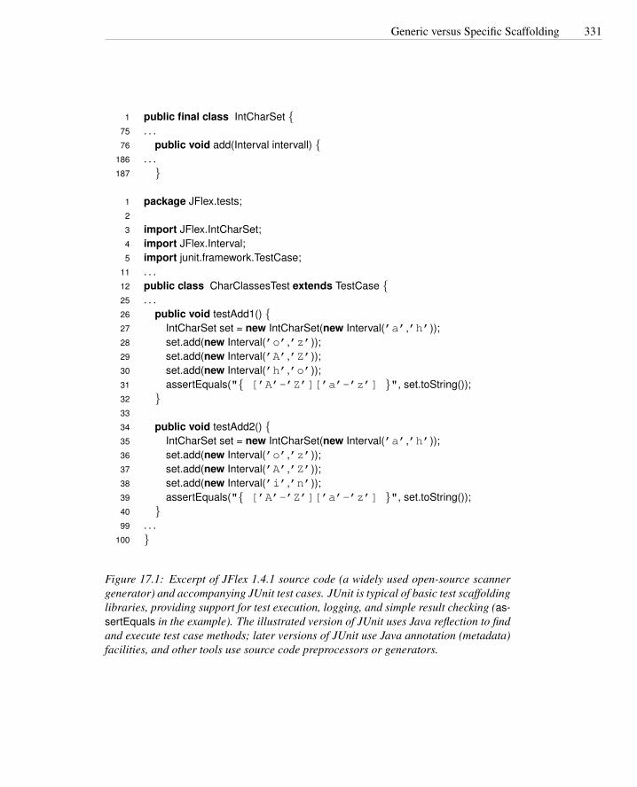
Generic versus Specific Scaffolding 331
1 public final class IntCharSet {75 . . .76 public void add(Interval intervall) {
186 . . .187 }
1 package JFlex.tests;2
3 import JFlex.IntCharSet;4 import JFlex.Interval;5 import junit.framework.TestCase;
11 . . .12 public class CharClassesTest extends TestCase {25 . . .26 public void testAdd1() {27 IntCharSet set = new IntCharSet(new Interval(’a’,’h’));28 set.add(new Interval(’o’,’z’));29 set.add(new Interval(’A’,’Z’));30 set.add(new Interval(’h’,’o’));31 assertEquals("{ [’A’-’Z’][’a’-’z’] }", set.toString());32 }33
34 public void testAdd2() {35 IntCharSet set = new IntCharSet(new Interval(’a’,’h’));36 set.add(new Interval(’o’,’z’));37 set.add(new Interval(’A’,’Z’));38 set.add(new Interval(’i’,’n’));39 assertEquals("{ [’A’-’Z’][’a’-’z’] }", set.toString());40 }99 . . .
100 }
Figure 17.1: Excerpt of JFlex 1.4.1 source code (a widely used open-source scannergenerator) and accompanying JUnit test cases. JUnit is typical of basic test scaffoldinglibraries, providing support for test execution, logging, and simple result checking (as-sertEquals in the example). The illustrated version of JUnit uses Java reflection to findand execute test case methods; later versions of JUnit use Java annotation (metadata)facilities, and other tools use source code preprocessors or generators.

332 Test Execution
unit and small-scale integration testing. For example, a database query may be replacedby a stub that provides only a fixed set of responses to particular query strings.
17.5 Test Oracles
It is little use to execute a test suite automatically if execution results must be manuallyinspected to apply a pass/fail criterion. Relying on human intervention to judge testoutcomes is not merely expensive, but also unreliable. Even the most conscientiousand hard-working person cannot maintain the level of attention required to identify onefailure in a hundred program executions, little more one or ten thousand. That is a jobfor a computer.
Software that applies a pass/fail criterion to a program execution is called a testoracle, often shortened to oracle. In addition to rapidly classifying a large number∆ test oracle
of test case executions, automated test oracles make it possible to classify behaviorsthat exceed human capacity in other ways, such as checking real-time response againstlatency requirements or dealing with voluminous output data in a machine-readablerather than human-readable form.
Ideally, a test oracle would classify every execution of a correct program as passingand would detect every program failure. In practice, the pass/fail criterion is usuallyimperfect. A test oracle may apply a pass/fail criterion that reflects only part of the ac-tual program specification, or is an approximation, and therefore passes some programexecutions it ought to fail. Several partial test oracles (perhaps applied with differentparts of the test suite) may be more cost-effective than one that is more comprehensive.A test oracle may also give false alarms, failing an execution that it ought to pass. Falsealarms in test execution are highly undesirable, not only because of the direct expenseof manually checking them, but because they make it likely that real failures will beoverlooked. Nevertheless sometimes the best we can obtain is an oracle that detectsdeviations from expectation that may or may not be actual failures.
One approach to judging correctness — but not the only one — compares the actualoutput or behavior of a program with predicted output or behavior. A test case with acomparison-based oracle relies on predicted output that is either precomputed as partcomparison-based
oracle of the test case specification or can be derived in some way independent of the programunder test. Precomputing expected test results is reasonable for a small number ofrelatively simple test cases, and is still preferable to manual inspection of programresults because the expense of producing (and debugging) predicted results is incurredonce and amortized over many executions of the test case.
Support for comparison-based test oracles is often included in a test harness pro-gram or testing framework. A harness typically takes two inputs: (1) the input to theprogram under test (or can be mechanically transformed to a well-formed input), and(2) the predicted output. Frameworks for writing test cases as program code likewiseprovide support for comparison-based oracles. The assertEquals method of JUnit, il-lustrated in Figure 17.1, is a simple example of comparison-based oracle support.
Comparison-based oracles are useful mainly for small, simple test cases, but some-times expected outputs can also be produced for complex test cases and large test suites.Capture-replay testing, a special case of this in which the predicted output or behavior

Test Oracles 333
Program Under Test
Test Input
Expected Output Compare
Test Harnesswith Comparison Based
Oracle
Pass/Fail
Test Case
Figure 17.2: A test harness with a comparison-based test oracle processes test casesconsisting of (program input, predicted output) pairs.
is preserved from an earlier execution, is discussed in this chapter. A related approachis to capture the output of a trusted alternate version of the program under test. Forexample, one may produce output from a trusted implementation that is for some rea-son unsuited for production use; it may too slow or may depend on a component that isnot available in the production environment. It is not even necessary that the alternativeimplementation be more reliable than the program under test, as long as it is sufficientlydifferent that the failures of the real and alternate version are likely to be independent,and both are sufficiently reliable that not too much time is wasted determining whichone has failed a particular test case on which they disagree.
A third approach to producing complex (input, output) pairs is sometimes possible:It may be easier to produce program input corresponding to a given output than viceversa. For example, it is simpler to scramble a sorted array than to sort a scrambledarray.
A common misperception is that a test oracle always requires predicted programoutput to compare to the output produced in a test execution. In fact, it is often possibleto judge output or behavior without predicting it. For example, if a program is requiredto find a bus route from station A to station B, a test oracle need not independentlycompute the route to ascertain that it is in fact a valid route that starts at A and ends atB.
Oracles that check results without reference to a predicted output are often partial,in the sense that they can detect some violations of the actual specification but not oth-ers. They check necessary but not sufficient conditions for correctness. For example,if the specification calls for finding the optimum bus route according to some metric, partial oracle
a validity check is only a partial oracle because it does not check optimality. Similarly,checking that a sort routine produces sorted output is simple and cheap, but it is onlya partial oracle because the output is also required to be a permutation of the input. Acheap partial oracle that can be used for a large number of test cases is often combinedwith a more expensive comparison-based oracle that can be used with a smaller set oftest cases for which predicted output has been obtained.
Ideally, a single expression of a specification would serve both as a work assign-ment and as a source from which useful test oracles were automatically derived. Spec-
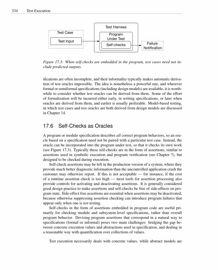
334 Test Execution
Program Under Test
Test InputSelf-checks
Test Harness
Failure Notification
Test Case
Figure 17.3: When self-checks are embedded in the program, test cases need not in-clude predicted outputs.
ifications are often incomplete, and their informality typically makes automatic deriva-tion of test oracles impossible. The idea is nonetheless a powerful one, and whereverformal or semiformal specifications (including design models) are available, it is worth-while to consider whether test oracles can be derived from them. Some of the effortof formalization will be incurred either early, in writing specifications, or later whenoracles are derived from them, and earlier is usually preferable. Model-based testing,in which test cases and test oracles are both derived from design models are discussedin Chapter 14.
17.6 Self-Checks as Oracles
A program or module specification describes all correct program behaviors, so an ora-cle based on a specification need not be paired with a particular test case. Instead, theoracle can be incorporated into the program under test, so that it checks its own work(see Figure 17.3). Typically these self-checks are in the form of assertions, similar toassertions used in symbolic execution and program verification (see Chapter 7), butdesigned to be checked during execution.
Self-check assertions may be left in the production version of a system, where theyprovide much better diagnostic information than the uncontrolled application crash thecustomer may otherwise report. If this is not acceptable — for instance, if the costof a runtime assertion check is too high — most tools for assertion processing alsoprovide controls for activating and deactivating assertions. It is generally consideredgood design practice to make assertions and self-checks be free of side-effects on pro-gram state. Side-effect free assertions are essential when assertions may be deactivated,because otherwise suppressing assertion checking can introduce program failures thatappear only when one is not testing.
Self-checks in the form of assertions embedded in program code are useful pri-marily for checking module and subsystem-level specifications, rather than overallprogram behavior. Devising program assertions that correspond in a natural way tospecifications (formal or informal) poses two main challenges: bridging the gap be-tween concrete execution values and abstractions used in specification, and dealing ina reasonable way with quantification over collections of values.
Test execution necessarily deals with concrete values, while abstract models are

Self-Checks as Oracles 335
indispensable in both formal and informal specifications. Chapter 7 (page 110) de-scribes the role of abstraction functions and structural invariants in specifying concreteoperational behavior based on an abstract model of the internal state of a module. Theintended effect of an operation is described in terms of a precondition (state before theoperation) and postcondition (state after the operation), relating the concrete state tothe abstract model. Consider again a specification of the get method of java.util.Mapfrom Chapter 7, with pre- and postconditions expressed as the Hoare triple
(|〈k,v〉 ∈ φ(dict)|)o = dict.get(k)(|o = v|)
φ is an abstraction function that constructs the abstract model type (sets of key, valuepairs) from the concrete data structure. φ is a logical association that need not beimplemented when reasoning about program correctness. To create a test oracle, it isuseful to have an actual implementation of φ . For this example, we might implementa special observer method that creates a simple textual representation of the set of(key, value) pairs. Assertions used as test oracles can then correspond directly to thespecification. Besides simplifying implementation of oracles by implementing thismapping once and using it in several assertions, structuring test oracles to mirror acorrectness argument is rewarded when a later change to the program invalidates somepart of that argument (e.g., by changing the treatment of duplicates or using a differentdata structure in the implementation).
In addition to an abstraction function, reasoning about the correctness of internalstructures usually involves structural invariants, that is, properties of the data structurethat are preserved by all operations. Structural invariants are good candidates for selfchecks implemented as assertions. They pertain directly to the concrete data structureimplementation, and can be implemented within the module that encapsulates that datastructure. For example, if a dictionary structure is implemented as a red-black tree oran AVL tree, the balance property is an invariant of the structure that can be checkedby an assertion within the module. Figure 17.4 illustrates an invariant check found inthe source code of the Eclipse programming invariant.
There is a natural tension between expressiveness that makes it easier to write andunderstand specifications, and limits on expressiveness to obtain efficient implemen-tations. It is not much of a stretch to say that programming languages are just formalspecification languages in which expressiveness has been purposely limited to ensurethat specifications can be executed with predictable and satisfactory performance. Animportant way in which specifications used for human communication and reasoningabout programs are more expressive and less constrained than programming languagesis that they freely quantify over collections of values. For example, a specification ofdatabase consistency might state that account identifiers are unique; that is, for all ac-count records in the database, there does not exist another account record with the sameidentifier.
It is sometimes straightforward to translate quantification in a specification state-ment into iteration in a program assertion. In fact, some run-time assertion checking
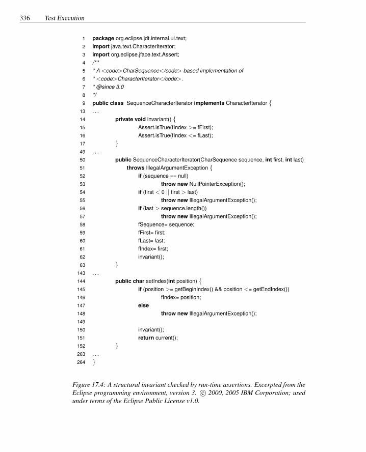
336 Test Execution
1 package org.eclipse.jdt.internal.ui.text;2 import java.text.CharacterIterator;3 import org.eclipse.jface.text.Assert;4 /**5 * A <code>CharSequence</code> based implementation of6 * <code>CharacterIterator</code>.7 * @since 3.08 */9 public class SequenceCharacterIterator implements CharacterIterator {
13 . . .14 private void invariant() {15 Assert.isTrue(fIndex >= fFirst);16 Assert.isTrue(fIndex <= fLast);17 }49 . . .50 public SequenceCharacterIterator(CharSequence sequence, int first, int last)51 throws IllegalArgumentException {52 if (sequence == null)53 throw new NullPointerException();54 if (first < 0 || first > last)55 throw new IllegalArgumentException();56 if (last > sequence.length())57 throw new IllegalArgumentException();58 fSequence= sequence;59 fFirst= first;60 fLast= last;61 fIndex= first;62 invariant();63 }
143 . . .144 public char setIndex(int position) {145 if (position >= getBeginIndex() && position <= getEndIndex())146 fIndex= position;147 else148 throw new IllegalArgumentException();149
150 invariant();151 return current();152 }263 . . .264 }
Figure 17.4: A structural invariant checked by run-time assertions. Excerpted from theEclipse programming environment, version 3. c© 2000, 2005 IBM Corporation; usedunder terms of the Eclipse Public License v1.0.

Capture and Replay 337
systems provide quantifiers that are simply interpreted as loops. This approach canwork when collections are small and quantifiers are not too deeply nested, particu-larly in combination with facilities for selectively disabling assertion checking so thatthe performance cost is incurred only when testing. Treating quantifiers as loops doesnot scale well to large collections and cannot be applied at all when a specificationquantifies over an infinite collection.1 For example, it is perfectly reasonable for aspecification to state that the route found by a trip-planning application is the shortestamong all possible routes between two points, but it is not reasonable for the routeplanning program to check its work by iterating through all possible routes.
The problem of quantification over large sets of values is a variation on the basicproblem of program testing, which is that we cannot exhaustively check all programbehaviors. Instead, we select a tiny fraction of possible program behaviors or inputsas representatives. The same tactic is applicable to quantification in specifications. Ifwe cannot fully evaluate the specified property, we can at least select some elementsto check (though at present we know of no program assertion packages that supportsampling of quantifiers). For example, although we cannot afford to enumerate allpossible paths between two points in a large map, we may be able to compare to asample of other paths found by the same procedure. As with test design, good samplesrequire some insight into the problem, such as recognizing that if the shortest path fromA to C passes through B, it should be the concatenation of the shortest path from A toB and the shortest path from B to C.
A final implementation problem for self-checks is that asserted properties some-times involve values that are either not kept in the program at all (so-called ghost vari-ables) or values that have been replaced (“before” values). A specification of noninter-ference between threads in a concurrent program may use ghost variables to track entryand exit of threads from a critical section. The postcondition of an in-place sort oper-ation will state that the new value is sorted and a permutation of the input value. Thispermutation relation refers to both the “before” and “after” values of the object to besorted. A run-time assertion system must manage ghost variables and retained “before”values and must ensure that they have no side-effects outside assertion checking.
17.7 Capture and Replay
Sometimes it is difficult to either devise a precise description of expected behavioror adequately characterize correct behavior for effective self-checks. For example,while many properties of a program with a graphical interface may be specified in amanner suitable for comparison-based or self-check oracles, some properties are likelyto require a person to interact with the program and judge its behavior. If one cannotcompletely avoid human involvement in test case execution, one can at least avoid
1It may seem unreasonable for a program specification to quantify over an infinite collection, but in fact itcan arise quite naturally when quantifiers are combined with negation. If we say “there is no integer greaterthan 1 that divides k evenly,” we have combined negation with “there exists” to form a statement logicallyequivalent to universal (“for all”) quantification over the integers. We may be clever enough to realize thatit suffices to check integers between 2 and
√k, but that is no longer a direct translation of the specification
statement.

338 Test Execution
unnecessary repetition of this cost and opportunity for error. The principle is simple.The first time such a test case is executed, the oracle function is carried out by a human,and the interaction sequence is captured. Provided the execution was judged (by thehuman tester) to be correct, the captured log now forms an (input, predicted output)pair for subsequent automated retesting.
The savings from automated retesting with a captured log depends on how manybuild-and-test cycles we can continue to use it in, before it is invalidated by somechange to the program. Distinguishing between significant and insignificant variationsfrom predicted behavior, in order to prolong the effective lifetime of a captured log,is a major challenge for capture/replay testing. Capturing events at a more abstractlevel suppresses insignificant changes. For example, if we log only the actual pixels ofwindows and menus, then changing even a typeface or background color can invalidatean entire suite of execution logs.
Mapping from concrete state to an abstract model of interaction sequences is some-times possible but is generally quite limited. A more fruitful approach is capturinginput and output behavior at multiple levels of abstraction within the implementation.We have noted the usefulness of a layer in which abstract input events (e.g., selectionof an object) are captured in place of concrete events (left mouse button depressed withmouse positioned at 235, 718). Typically, there is a similar abstract layer in graphicaloutput, and much of the capture/replay testing can work at this level. Small changesto a program can still invalidate a large number of execution logs, but it is much morelikely that an insignificant detail can either be ignored in comparisons or, even better,the abstract input and output can be systematically transformed to reflect the intendedchange.
Further amplification of the value of a captured log can be obtained by varying thelogged events to obtain additional test cases. Creating meaningful and well-formedvariations also depends on the abstraction level of the log. For example, it is simpler tovary textual content recorded in a log than to make an equivalent change to a recordedbitmap representation of that text.
Open Research Issues
Tools to generate some kinds of scaffolding from program code have been constructed,as have tools to generate some kinds of test oracles from design and specification docu-ments. Fuller support for creating test scaffolding might bring these together, combin-ing information derivable from program code itself with information from design andspecification to create at least test harnesses and oracles. Program transformation andprogram analysis techniques have advanced quickly in the last decade, suggesting thata higher level of automation than in the past should now be attainable.
Further Reading
Techniques for automatically deriving test oracles from formal specifications have beendescribed for a wide variety of specification notations. Good starting points in this lit-

Capture and Replay 339
erature include Peters and Parnas [PP98] on automatic extraction of test oracles from aspecification structured as tables; Gannon et al. [GMH81] and Bernot et al. [BGM91]on derivation of test oracles from algebraic specifications; Doong and Frankl [DF94]on an approach related to algebraic specifications but adapted to object-oriented pro-grams; Bochmann and Petrenko [vBP94] on derivation of test oracles from finite statemodels, particularly (but not only) for communication protocols; and Richardson etal. [RAO92] on a general approach to deriving test oracles from multiple specificationlanguages, including a form of temporal logic and the Z modeling language.
Rosenblum [Ros95] describes a system for writing test oracles in the form of pro-gram assertions and assesses their value. Memon and Soffa [MS03] assesses the impactof test oracles and automation for interactive graphical user interface (GUI) programs.Ostrand et al. [OAFG98] describe capture/replay testing for GUI programs.
Mocks for simulating the environment of a module are described by Saff and Ernst[SE04]. Husted and Massol [HM03] is a guide to the popular JUnit testing framework.Documentation for JUnit and several similar frameworks for various languages andsystems are also widely available on the Web.
Related Topics
Readers interested primarily in test automation or in automation of other aspects ofanalysis and test may wish to continue reading with Chapter 23.
Exercises
17.1. Voluminous output can be a barrier to naive implementations of comparison-based oracles. For example, sometimes we wish to show that some abstractionof program behavior is preserved by a software change. The naive approach isto store a detailed execution log of the original version as predicted output, andcompare that to a detailed execution log of the modified version. Unfortunately,a detailed log of a single execution is quite lengthy, and maintaining detailedlogs of many test case executions may be impractical. Suggest more efficient ap-proaches to implementing comparison-based test oracles when it is not possibleto store the whole output.
17.2. We have described as an ideal but usually unachievable goal that test oraclescould be derived automatically from the same specification statement used torecord and communicate the intended behavior of a program or module. To whatextent does the “test first” approach of extreme programming (XP) achieve thisgoal? Discuss advantages and limitations of using test cases as a specificationstatement.
17.3. Often we can choose between on-line self-checks (recognizing failures as theyoccur) and producing a log of events or states for off-line checking. What con-siderations might motivate one choice or the other?

340 Test Execution
Chapter 18
Inspection
Software inspections are manual, collaborative reviews that can be applied to any soft-ware artifact from requirements documents to source code to test plans. Inspectioncomplements testing by helping check many properties that are hard or impossible toverify dynamically. Their flexibility makes inspection particularly valuable when other,more automated analyses are not applicable.
Required Background
• Chapter 2This chapter discusses complementarities and trade-offs between test and analy-sis, and motivates the need for alternatives to testing.
18.1 Overview
Inspection is a low-tech but effective analysis technique that has been extensively usedin industry since the early 1970s. It is incorporated in many standards, including theCapability Maturity Model (CMM and CMMI) and the ISO 9000 standards, and is akey element of verification- and test-oriented processes such as the Cleanroom, SRETand XP processes.1
Inspection is a systematic, detailed review of artifacts to find defects and assessquality. It can benefit from tool support, but it can also be executed manually. In-spection is most commonly applied to source code, but can be applied to all kinds ofartifacts during the whole development cycle. It is effective in revealing many defectsthat testing cannot reveal or can reveal only later and at higher cost.
Inspection also brings important education and social benefits. Junior developersquickly learn standards for specification and code while working as inspectors, andexpert developers under pressure are less tempted to ignore standards. The sidebar onpage 342 summarizes the chief social and educational benefits of inspection.
1See the sidebars in Chapter 20 for additional information on Cleanroom, SRET, and XP.
341

342 Inspection
Social and Educational Benefits of InspectionWhile the direct goal of inspection is to find and remove defects, social and educa-
tional effects may be equally important.Inspection creates a powerful social incentive to present acceptable work products,
even when there is no direct tie to compensation or performance evaluation. The classicgroup inspection process, in which the author of the work under review is requiredto be a passive participant, answering questions but not volunteering explanation orjustification for the work until asked, especially magnifies the effect; it is not easy tolisten quietly while one’s work is publicly picked apart by peers.
Inspection is also an effective way to form and communicate shared norms in anorganization, not limited to rules that are explicit in checklists. The classic inspectionprocess prohibits problem solving in the inspection meeting itself, but the necessityof such a rule to maintain momentum in the inspection meeting is evidence for thegeneral rule that, given opportunity, developers and other technical professionals arequick to share experience and knowledge relevant to problems found in a colleague’swork. When a new practice or standard is introduced in an organization, inspectionpropagates awareness and shared understanding.
New staff can be almost immediately productive, individually reviewing work prod-ucts against checklists, accelerating their familiarization with organization standardsand practices. Group inspection roles require some experience, but can likewise bemore effective than traditional training in integrating new staff.
The social and educational facets of inspection processes should be taken into ac-count when designing an inspection process or weighing alternatives or variations toan existing process. If the alternatives are weighed by fault-finding effectiveness alone,the organization could make choices that appear to be an improvement on that dimen-sion, but are worse overall.

The Inspection Team 343
18.2 The Inspection Team
Inspections are characterized by roles, process, and reading techniques, i.e., who theinspectors are, how they organize their work and synchronize their activities, and howthey examine the inspected artifacts.
Inspection is not a full-time job: Many studies indicate that inspectors’ productivitydrops dramatically after two hours of work, and suggests no more than two inspectionsessions per day. Thus, inspectors are usually borrowed from other roles: junior andsenior software and test engineers, project and quality managers, software analysts,software architects, and technical writers. The same studies highlight the delicate rela-tion between inspectors and developers: The efficacy of inspection can vanish if devel-opers feel they are being evaluated. In classic approaches to inspection, managers andsenior engineers who participate in inspection sessions are often borrowed from otherprojects to avoid misinterpreting the goals of inspection.
Inspectors must be selected in a way that balances perspectives, background knowl-edge, and cost. A developer is most knowledgeable about his own work, and is aninvaluable resource in inspection, but he cannot forget days or weeks of hard develop-ment work to see clearly all the details that are apparent to someone reading an artifactfor the first time. Inspection can benefit from discussion among many inspectors withdiffering perspectives and expertise, but the cost of inspection grows with the size ofthe inspection team.
Classic inspection postulates groups from four to six inspectors, but recent stud-ies question the efficacy advantages of large groups of inspectors over groups of two.Modern approaches prescribe different levels of inspection: simple checks performedby single inspectors and complex check performed by groups of two inspectors, reserv-ing larger groups for inspections requiring special combinations of expertise.
Single inspectors are usually junior engineers not involved in development of theartifact under inspection. They combine inspection with training, learning basic stan-dards for specification and programming by checking compliance of artifacts withthose standards. Junior engineers are usually paired with senior engineers for checkingcomplex properties. The senior engineer acts as moderator; he or she is in charge oforganizing the inspection process and is responsible for the inspection results, whilethe junior engineer participates in the inspection and the discussion.
Large groups of inspectors (from four to six) balance junior and senior engineers,and may include the developer of the artifact under inspection. A senior engineer,usually a manager borrowed from a different project, plays the role of the moderator,organizing the process and being responsible for the results. Other software and testengineers, both senior and junior, are in charge of reading the inspected artifact, and ofdiscussing the possible problems connected to the relevant elements. The developer ispresent when the inspection requires detailed knowledge that cannot be easily acquiredwithout being involved in the development. This happens for example, when inspectingcomplex modules looking for semantics or integration problems.
Developers must be motivated to collaborate constructively in inspection, ratherthan hiding problems and sabotaging the process. Reward mechanisms can influencethe developers’ attitude and must be carefully designed to avoid perverse effects. Forexample, fault density is sometimes used as a metric of developer performance. An

344 Inspection
assessment of fault density that includes faults revealed by inspection may discouragedevelopers from constructive engagement in the inspection process and encourage themto hide faults during inspection instead of highlighting them. At the very least, faultsthat escape inspection must carry a higher weight than those found during inspection.Naive incentives that reward developers for finding faults during inspection are apt tobe counterproductive because they punish the careful developer for bringing a high-quality code to the inspection.
18.3 The Inspection Process
Inspection is not merely reading, but a systematic process that promotes efficiency andrepeatability. Because inspection is expensive and not incremental (that is, reinspec-tion after a change can be nearly as expensive as inspection of the original artifact), itmust be placed to reveal faults as early as possible, but late enough to avoid excessiverepetition. Consider, for example, source code inspection. Inspecting software still un-der construction may waste inspection effort on elements that are likely to change, butwaiting until after integration and system test wastes testing effort on faults that couldhave been more cost-effectively removed by inspection.
Different inspection activities may be scheduled at distinct development phases.We can for example check for consistency and completeness of comments and codingstandards before testing, and we can check for semantic consistency of the softwareafter testing, to focus on key semantic aspects without being distracted by faults thatcan be easily identified by simple test cases.
The inspection process is usually composed of three main phases: preparatory,review, and follow-up. In the preparatory phase, inspectors check that the artifactsto be inspected are ready, assign inspection roles, acquire the information needed forinspections, plan individual inspection activities, and schedule inspection meetings.
In the review phase, inspectors review the artifact individually and in teams. Re-views follow a systematic and consistent process. The classic and most widely usedinspection technique is based on following a checklist while reading the artifact, asdescribed in Section 18.4. Other approaches include use-case and abstraction-drivenreading techniques, designed to overcome delocalization in object-oriented programs,the many external references that make it difficult to inspect an individual class in anobject-oriented program without global knowledge of the program structure.
In the follow-up phase, inspectors notify developers of inspection results and sched-ule additional inspection activities if needed. The results of the review phase are sum-marized in reports that indicate possible problems. Developers and test designers ex-amine the reports to identify actual defects and schedule their removal. The team mayschedule follow-up checks that could be as simple as ascertaining that a correctionhas been made or as complex as a full re-inspection. Simple checks may use the re-ports themselves as checklists. If, for example, a previous inspection reported missingelements in the code, they may simply check that the elements have been added. Ifthe previous inspection reported logical problems, on the other hand, the team mightschedule a new review after the corrective actions to ensure the quality of the newversion.

Checklists 345
18.4 Checklists
Checklists are a core element of classic inspection. They summarize the experienceaccumulated in previous projects, and drive the review sessions. A checklist containsa set of questions that help identify defects in the inspected artifact, and verify that theartifact complies with company standards. A good checklist should be updated regu-larly to remove obsolete elements and to add new checks suggested by the experienceaccumulated in new projects. We can, for example, remove some simple checks aboutcoding standards after introducing automatic analyzers that enforce the standards, orwe can add specific semantic checks to avoid faults that caused problems in recentprojects.
Checklists may be used to inspect a large variety of artifacts, including require-ments and design specifications, source code, test suites, reports, and manuals. Thecontents of checklists may vary greatly to reflect the different properties of the variousartifacts, but all checklists share a common structure that facilitates their use in reviewsessions. Review sessions must be completed within a relatively short time (no longerthan two hours) and may require teams of different size and expertise (from a singlejunior programmer to teams of senior analysts). Length and complexity of checklistsmust reflect their expected use. We may have fairly long checklists with simple ques-tions for simple syntactic reviews, and short checklists with complex questions forsemantic reviews.
Modern checklists are structured hierarchically and are used incrementally. Check-lists with simple checks are used by individual inspectors in the early stages of inspec-tion, while checklists with complex checks are used in group reviews in later inspectionphases. The preface of a checklist should indicate the type of artifact and inspectionthat can be done with that checklist and the level of expertise required for the inspec-tion.
The sidebar on page 346 shows an excerpt of a checklist for a simple Java codeinspection and the sidebar on page 347 shows an excerpt of a checklist for a morecomplex review of Java programs.
A common checklist organization, used in the examples in this chapter, consistsof a set of features to be inspected and a set of items to be checked for each feature.Organizing the list by features helps direct the reviewers’ attention to the appropriateset of checks during review. For example, the simple checklist on page 346 containschecks for file headers, file footers, import sections, class declarations, classes, andidiomatic methods. Inspectors will scan the Java file and select the appropriate checksfor each feature.
The items to be checked ask whether certain properties hold. For example, the fileheader should indicate the identity of the author and the current maintainer, a crossreference to the design entity corresponding to the code in the file, and an overviewof the structure of the package. All checks are expressed so that a positive answerindicates compliance. This helps the quality manager spot possible problems, whichwill correspond to “no” answers in the inspection reports.
Inspectors check the items, answer “yes” or “no” depending on the status of theinspected feature, and add comments with detailed information. Comments are com-mon when the inspectors identify violations, and they help identify and localize the

346 Inspection
Java Checklist: Level 1 inspection (single-pass read-through, context independent)FEATURES (where to look and how to check):
Item (what to check)FILE HEADER: Are the following items included and consistent? yes no comments
Author and current maintainer identityCross-reference to design entityOverview of package structure, if the class is theprincipal entry point of a package
FILE FOOTER: Does it include the following items? yes no commentsRevision log to minimum of 1 year or at least tomost recent point release, whichever is longer
IMPORT SECTION: Are the following requirements satisfied? yes no commentsBrief comment on each import with the exceptionof standard set: java.io.*, java.util.*Each imported package corresponds to a depen-dence in the design documentation
CLASS DECLARATION: Are the following requirements satisfied? yes no commentsThe visibility marker matches the design documentThe constructor is explicit (if the class is not static)The visibility of the class is consistent with the de-sign document
CLASS DECLARATION JAVADOC: Does the Javadoc header include: yes no commentsOne sentence summary of class functionalityGuaranteed invariants (for data structure classes)Usage instructions
CLASS: Are names compliant with the following rules? yes no commentsClass or interface: CapitalizedWithEachInternal-WordCapitalizedSpecial case: If class and interface have same basename, distinguish as ClassNameIfc and Class-NameImplException: ClassNameEndsWithExceptionConstants (final):ALL CAPS WITH UNDERSCORESField name: capsAfterFirstWord.name must be meaningful outside of context
IDIOMATIC METHODS: Are names compliant with the following rules? yes no commentsMethod name: capsAfterFirstWordLocal variables: capsAfterFirstWord.Name may be short (e.g., i for an integer) if scopeof declaration and use is less than 30 lines.Factory method for X: newXConverter to X: toXGetter for attribute x: getX();Setter for attribute x: void setX

Checklists 347
Java Checklist: Level 2 inspection (comprehensive review in context)FEATURES (where to look and how to check):
Item (what to check)DATA STRUCTURE CLASSES: Are the following require-ments satisfied?
yes no comments
The class keeps a design secretThe substitution principle is respected: Instance of class can be usedin any context allowing instance of superclass or interfaceMethods are correctly classified as constructors, modifiers, and ob-serversThere is an abstract model for understanding behaviorThe structural invariants are documented
FUNCTIONAL (STATELESS) CLASSES: Are the followingrequirements satisfied?
yes no comments
The substitution principle is respected: Instance of class can be usedin any context allowing instance of superclass or interface
METHODS: Are the following requirements satisfied? yes no commentsThe method semantics are consistent with similarly named meth-ods. For example, a “put” method should be semantically consistentwith “put” methods in standard data structure librariesUsage examples are provided for nontrivial methods
FIELDS: Are the following requirements satisfied? yes no commentsThe field is necessary (cannot be a method-local variable)Visibility is protected or private, or there is an adequate and docu-mented rationale for public accessComment describes the purpose and interpretation of the fieldAny constraints or invariants are documented in either field or classcomment header
DESIGN DECISIONS: Are the following requirements satis-fied?
yes no comments
Each design decision is hidden in one class or a minimum numberof closely related and co-located classesClasses encapsulating a design decision do not unnecessarily de-pend on other design decisionsAdequate usage examples are provided, particularly of idiomaticsequences of method callsDesign patterns are used and referenced where appropriateIf a pattern is referenced: The code corresponds to the documentedpattern

348 Inspection
violations. For example, the inspectors may indicate which file headers do not containall the required information and which information is missing. Comments can also beadded when the inspectors do not identify violations, to clarify the performed checks.For example, the inspectors may indicate that they have not been able to check if themaintainer indicated in the header is still a member of the staff of that project.
Checklists should not include items that can be more cost-effectively checked withautomated test or analysis techniques. For example, the checklist at page 346 doesnot include checks for presence in the file header of file title, control identifier, copy-right statement and list of classes, since such information is added automatically andthus does not require manual checks. On the other hand, it asks the inspector to verifythe presence of references to the author and maintainer and of cross reference to thecorresponding design entities, since this checklist is used in a context where such infor-mation is not inserted automatically. When adopting an environment that automaticallyupdates author and maintainer information and checks cross references to design en-tities, we may remove the corresponding checks from the checklist, and increase theamount of code that can be inspected in a session, or add new checks for reducingdifferent problems experienced in new projects.
Properties should be as objective and unambiguous as possible. Complete indepen-dence from subjective judgment may not be possible, but must be pursued. For examplebroad properties like “Comments are complete?” or “Comments are well written?” askfor a subjective judgment, and raise useless and contentious discussions among inspec-tors and the authors of an artifact undergoing inspection. Checklist items like “Briefcomment on each import with the exception of standard set: java.io.*, java.util.*” or“One sentence summary of class functionality” address the same purpose more effec-tively.
Items should also be easy to understand. The excerpts in the sidebars on pages346 and 347 list items to be checked, but for each item, the checklist should provide adescription, motivations, and examples. Figure 18.1 shows a complete description ofone of the items of the sidebars.
Checking for presence of comments is easy to automate, but checking contents formeaning and usefulness is apt to require human judgment. For example, we can easilyautomate a check that there is a comment for each import section or class, but wecannot automatically check that the comment is meaningful and properly summarizesthe need for the import section or the functionality of the class.
Descriptions, motivations and examples may be lengthy, and displaying them di-rectly in the checklist reduces an inspector’s ability to quickly scan through the check-list to identify items relevant to each feature under review. Therefore, explanatory ma-terial is typically provided separately, linked to the inspection checklist by reference(e.g., a page number for printed documentation or a hyperlink in a Web-based display).Inexperienced inspectors and teams reviewing complex items may access the detailsto resolve questions and controversies that arise during inspection, but frequency ofreference declines with experience.
Checklists can be used in many different contexts. The sidebar on page 350 showsan excerpt of a checklist for comprehensive review of test plans. That checklist assumesthat the document includes a standard set of sections, whose presence can be easilychecked automatically, and is suited for experienced testers.
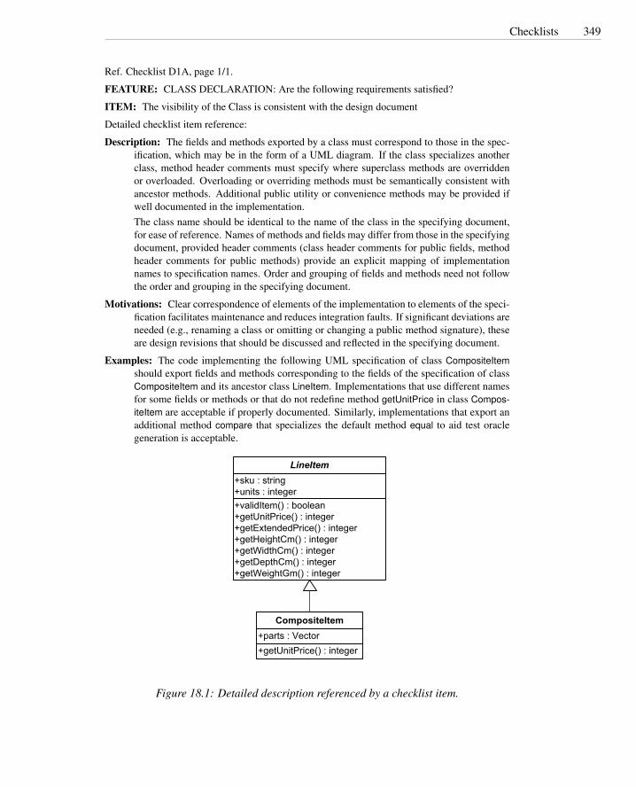
Checklists 349
Ref. Checklist D1A, page 1/1.
FEATURE: CLASS DECLARATION: Are the following requirements satisfied?
ITEM: The visibility of the Class is consistent with the design document
Detailed checklist item reference:
Description: The fields and methods exported by a class must correspond to those in the spec-ification, which may be in the form of a UML diagram. If the class specializes anotherclass, method header comments must specify where superclass methods are overriddenor overloaded. Overloading or overriding methods must be semantically consistent withancestor methods. Additional public utility or convenience methods may be provided ifwell documented in the implementation.The class name should be identical to the name of the class in the specifying document,for ease of reference. Names of methods and fields may differ from those in the specifyingdocument, provided header comments (class header comments for public fields, methodheader comments for public methods) provide an explicit mapping of implementationnames to specification names. Order and grouping of fields and methods need not followthe order and grouping in the specifying document.
Motivations: Clear correspondence of elements of the implementation to elements of the speci-fication facilitates maintenance and reduces integration faults. If significant deviations areneeded (e.g., renaming a class or omitting or changing a public method signature), theseare design revisions that should be discussed and reflected in the specifying document.
Examples: The code implementing the following UML specification of class CompositeItemshould export fields and methods corresponding to the fields of the specification of classCompositeItem and its ancestor class LineItem. Implementations that use different namesfor some fields or methods or that do not redefine method getUnitPrice in class Compos-iteItem are acceptable if properly documented. Similarly, implementations that export anadditional method compare that specializes the default method equal to aid test oraclegeneration is acceptable.
+validItem() : boolean+getUnitPrice() : integer+getExtendedPrice() : integer+getHeightCm() : integer+getWidthCm() : integer+getDepthCm() : integer+getWeightGm() : integer
+sku : string+units : integer
LineItem
+getUnitPrice() : integer+parts : Vector
CompositeItem
Figure 18.1: Detailed description referenced by a checklist item.

350 Inspection
TEST PLAN CHECKLIST: Comprehensive review in contextFEATURES (where to look and how to check):
Item (what to check)ITEMS TO BE TESTED OR ANALYZED: For each item, does theplan include:
yes no comments
A reference to the specification for the itemA reference to installation procedures for the item, if any
TEST AND ANALYSIS APPROACH: Are the following requirementssatisfied?
yes no comments
The test and analysis techniques to be applied are cost-effective foritems of this typeThe test and analysis techniques to be applied cover the relevantproperties cost-effectivelyThe description is sufficiently detailed to identify major tasks andestimate time and resources.
PASS/FAIL CRITERIA: Are the following requirements satisfied? yes no commentsThe criteria clearly indicate the pass/fail conditionsThe criteria are consistent with quality standards specified in thetest and analysis strategy
SUSPEND/RESUME CRITERIA: Are the following requirementssatisfied?
yes no comments
The criteria clearly indicate threshold conditions for suspending testand analysis due to excessive defectsThe criteria clearly indicate conditions for resuming test and analy-sis after suspension and rework
RISKS AND CONTINGENCIES: Are the following risks addressed? yes no commentsPersonnel risks (loss or unavailability of qualified staff)Technology risksSchedule risksDevelopment risksExecution risksRisks from critical requirements
CONTINGENCY PLAN: Are the following requirements satisfied? yes no commentsEach identified risk is adequately considered in the contingencyplan
TASK AND SCHEDULE: Are the following requirements satisfied? yes no commentsThe tasks cover all aspects that ought to be testedThe description of the tasks is completeThe relations among tasks are complete and consistentResource allocation and constraints are adequateThe schedule satisfies all milestonesCritical paths are minimized

Pair Programming 351
18.5 Pair Programming
Pair programming is a practice associated with agile processes, particularly ExtremeProgramming (XP).2 It can be viewed as a variation on program inspection. Two pro-grammers work side-by-side at a computer, continuously collaborating on the samecode. The two programmers alternate at the keyboard: While one programmer typesnew code, the other reviews and inspects the newly typed code. The programmer whois free from typing duties has more time for thinking about design and coding alterna-tives, evaluating the impact of design decisions, and checking for discrepancies withcoding rules. In short, while the code is being written, the programmer who is nottyping inspects the work of the other programmer, highlights possible problems anddiscusses alternative solutions. Thus, pair programming merges coding and inspectionactivities, eliminating the gap between classic coding and inspection phases.
In pair programming, the inspection activities are not driven by checklists, but arebased on shared programming practice and style. Programmers frequently alternateroles, both at a fine grain (inspector and coder) and more generally in working ondifferent parts of the code. Software components are not “owned” by individual pro-grammers, but are the collective responsibility of the team.
The practice of inspection requires an attitude toward the inspected artifacts aspublic documents that must conform to group standards and norms. Pair programmingmakes a shared style and norms a collective asset of the development team. Ideally,this should result in an attitude known as egoless programming, in which criticism ofartifacts is not regarded as criticism of the authors of those artifacts.
Pair programming is tied to a number of other practices that facilitate teamworkand concentration. As in conventional inspection, fatigue limits the amount of timethat a pair can work together effectively, so joint activities are interleaved with pausesand individual activities that may occupy up to half the total programming time. Inaddition, in the XP approach, pair programming is to be carried out in normal (8-hour) work days, without excessive overtime and without severe or unrealistic schedulepressure. It has been observed that longer work days and working weekends do notimprove productivity when extended beyond an occasional, brief “crunch” period, asconcentration waivers and developers spend more time on unproductive activities.
Also as in conventional inspection, a constructive attitude must be nurtured for ef-fective pair programming. In the classical group inspection process, the meeting con-vener acts as a mediator to keep comments constructive and avoid debates in which anauthor defends decisions that have been called into question. Since there is no mediatorin pair programming, responsibility for an open, nonpersonal and nondefensive discus-sion of decisions and alternatives falls to the programmers themselves. Alternation ofroles in pair programming emphasizes shared ownership of the artifact and discussionon the merits rather than on the basis of authority.
A superficial analysis of pair programming would suggest that using two program-mers instead of one should halve productivity. The empirical evidence available so farsuggests compensating effects of better use of time, better design choices and earlierdetection of defects leading to less time lost to rework and overall better quality.
2For additional details on XP see the sidebar on page 381 in Chapter 20.

352 Inspection
Open Research Issues
Active research topics in software inspection include adapting and extending inspectiontechniques for particular artifacts (e.g., object-oriented program code, specifications ofreal-time systems), automation to support inspection (e.g., remote and asynchronousinspections), and variations on process and procedures. Software inspection researchis characterized by an emphasis on empirical research methods, including classic con-trolled experiments.
The most valuable empirical studies do not merely report on whether practice Ais more or less effective than practice B, but rather help build up a more fundamentalmodel of how each practice works. In other words, the empirical research that willmatter in the long term is theory-based. Empirical research that addresses smallerquestions (e.g., the effect of varying some small part of practice A) is likely to havemore lasting value, as it reveals something about a principle that can be applied notonly to A and to B but, at some future time, to a new practice C, and over the long termcontributes to a coherent theory.
We have tried to indicate where some characteristics of effective inspection seem tocut across the particular inspection and review practices in use today, suggesting prin-ciples that will be equally important in variations on these approaches and on futureapproaches to inspection and review. To the extent that a body of general principles fordesigning inspection processes does develop, it will almost certainly draw from cogni-tive and social psychology and from management as well as from software engineeringresearch.
Inspection techniques have an irreducible core of manual effort (otherwise they arereclassified as program analysis), but that does not mean that automated tools are ir-relevant. Previous research on automated support for inspection has included tools tobring appropriate information quickly to hand (e.g., displaying the portions of an in-spection checklist relevant to each portion of a program code as it is being inspected),supporting same-time and asynchronous meetings at a distance, and providing richerinformation about the artifact being inspected through static analyses. We expect re-search on tool support for inspection and review to continue alongside development ofapproaches to inspection and better understanding of the basic principles of inspectionprocesses.
Further Reading
The classic group inspection process is known as Fagan inspections and is described byFagan [Fag86]. Industrial experience with software inspections in a large software de-velopment project is described by Russell [Rus91] and by Grady and van Slack [GS94].Gilb and Graham [GG93] is a widely used guidebook for applying software inspection.
Parnas and Weiss [PW85, HW01] describe a variant process designed to ensurethat every participant in the review process is actively engaged; it is a good exampleof interplay between the technical and social aspects of a process. Knight and Myers’phased inspections [KM93] are an attempt to make a more cost-effective deploymentof personnel in inspections, and they also suggest ways in which automation can be

Pair Programming 353
harnessed to improve efficiency. Perpich et al. [PPP+97] describe automation to facil-itate asynchronous inspection, as an approach to reducing the impact of inspection ontime-to-market.
There is a large research literature on empirical evaluation of the classic group in-spection and variations; Dunsmore, Roper, and Wood [DRW03] and Porter and John-son [PJ97] are notable examples. While there is a rapidly growing literature on em-pirical evaluation of pair programming as a pedagogical method, empirical evaluationsof pair programming in industry are (so far) fewer and decidedly mixed. Hulkko andAbrahamsson [HA05] found no empirical support for common claims of effectivenessand efficiency. Sauer et al. [SJLY00] lay out a behavioral science research programfor determining what makes inspection more or less effective and provide an excellentsurvey of relevant research results up to 2000, with suggestions for practical improve-ments based on those results.
Related Topics
Simple and repetitive checks can sometimes be replaced by automated analyses. Chap-ter 19 presents automated analysis techniques, while Chapter 23 discusses automatiza-tion problems.
Exercises
18.1. Your organization, which develops personal training monitors for runners andcyclists, has a software development team split between offices in Milan, Italy,and Eugene, Oregon. Team member roles (developers, test designers, technicalwriters, etc.) are fairly evenly distributed between locations, but some technicalexpertise is concentrated in one location or another. Expertise in mapping andgeographic information systems, for example, is concentrated mainly in Eugene,and expertise in device communication and GPS hardware mainly in Milan. Youare considering whether to organize inspection of requirements specifications,design documents, and program code primarily on a local, face-to-face basis, ordistributed with teleconference and asynchronous communication support be-tween sites. What are some of the potential advantages and pitfalls of eachchoice?
18.2. You have been asked to prepare a pilot study to measure the potential costs andbenefits of inspection in your organization. You are faced with several questionsin the design of this pilot study. Discuss these two:
(a) What specific costs-and-benefits will you try to measure? How might youmeasure and compare them?
(b) You could make cost-and-benefit comparisons within a single project (e.g.,inspecting some documents and artifacts but not others), or you could com-pare two fairly similar ongoing projects, using inspection in one but not theother. What are the advantages and disadvantages of each approach?

354 Inspection
18.3. Automated analysis should substitute for inspection where it is more cost-effective.How would you evaluate the cost of inspection and analysis to decide whether tosubstitute an analysis tool for a particular set of checklist items?
18.4. Inspection does not require tools but may benefit from tool support. Indicatethree tools that you think can reduce human effort and increase inspectors’ pro-ductivity. List tools in order of importance with respect to effort saving, explainwhy you ranked those tools highest, and indicate the conditions under whicheach tool may be particularly effective.
18.5. In classic inspection, some inspectors may remain silent and may not activelyparticipate in the inspection meeting. How would you modify inspection meet-ings to foster active participation of all inspectors?

Chapter 19
Program Analysis
A number of automated analyses can be applied to software specifications and programsource code. None of them are capable of showing that the specifications and the codeare functionally correct, but they can cost-effectively reveal some common defects, aswell as produce auxiliary information useful in inspections and testing.
Required Background
• Chapter 6This chapter describes data flow analysis, a basic technique used in many staticprogram analyses.
• Chapter 7This chapter introduces symbolic execution and describes how it is used forchecking program properties.
• Chapter 8This chapter discusses finite state verification techniques applicable to models ofprograms. Static analysis of programs is often concerned with extracting modelsto which these techniques can be applied.
19.1 Overview
Automated program analysis techniques complement test and inspection in two ways.First, automated program analyses can exhaustively check some important propertiesof programs, including those for which conventional testing is particularly ill-suited.Second, program analysis can extract and summarize information for inspection andtest design, replacing or augmenting human effort.
Conventional program testing is weak at detecting program faults that cause fail-ures only rarely or only under conditions that are difficult to control. For example,conventional program testing is not an effective way to find race conditions betweenconcurrent threads that interfere only in small critical sections, or to detect memory
355

356 Program Analysis
Concurrency FaultsConcurrent threads are vulnerable to subtle faults, including potential deadlocks
and data races. Deadlocks occur when each of a set of threads is blocked, waiting foranother thread in the set to release a lock. Data races occur when threads concurrentlyaccess shared resources while at least one is modifying that resource.
Concurrency faults are difficult to reveal and reproduce. The nondeterministic na-ture of concurrent programs does not guarantee the same execution sequence betweendifferent program runs. Thus programs that fail during one execution may not failduring other executions with the same input data, due to the different execution orders.
Concurrency faults may be prevented in several ways. Some programming styleseliminate concurrency faults by restricting program constructs. For example, somesafety critical applications do not allow more than one thread to write to any particu-lar shared memory item, eliminating the possibility of concurrent writes (write-writeraces). Other languages provide concurrent programming constructs that enable simplestatic checks. For example, protection of a shared variable in Java synchronized blocksis easy to check statically. Other constructs are more difficult to check statically. Forexample, C and C++ libraries that require individual calls to obtain and release a lockcan be used in ways that resist static verification.
access faults that only occasionally corrupt critical structures.1 These faults lead tofailures that are sparsely scattered in a large space of possible program behaviors, andare difficult to detect by sampling, but can be detected by program analyses that foldthe enormous program state space down to a more manageable representation.
Manual program inspection is also effective in finding some classes of faults thatare difficult to detect with testing. However, humans are not good at repetitive andtedious tasks, or at maintaining large amounts of detail. If program analysis is not ca-pable of completely replacing human inspection for some class of faults, it can at leastsupport inspection by automating extraction, summarization, and navigation throughrelevant information.
Analysis techniques examine either the program source code or program executiontraces. Techniques that work statically on the source code can exhaustively examinethe whole program source code and verify properties of all possible executions, but areprone to false alarms that result from summarizing all possible and some impossiblebehaviors together. Techniques that work dynamically on actual execution states andtraces do not suffer from the infeasible path problem, but cannot examine the executionspace exhaustively.
19.2 Symbolic Execution in Program Analysis
Chapter 7 describes how symbolic execution can prove that a program satisfies spec-ifications expressed in terms of invariants and pre and postconditions. Unfortunately,producing complete formal specifications with all the required pre and postconditions
1Concurrency and memory faults are further discussed in the sidebars on pages 356 and 357.

Symbolic Execution in Program Analysis 357
Memory FaultsDynamic memory access and allocation are vulnerable to program faults, including
null pointer dereference, illegal access, and memory leaks. These faults can lead tomemory corruption, misinterpretation or illegal access to memory structures, or mem-ory exhaustion. Common forms of these faults include the notorious buffer overflowproblem in C programs (whether the dynamic access is through a pointer or an out-of-bounds array index), access through a “dangling” pointer to either dynamically al-located memory or the local memory of a procedure (C function), and slow leakageof memory in shared dynamic data structures where it is difficult to determine whichportions of the structure are still accessible. These faults are difficult to reveal throughtesting because, in many cases, they do not cause immediate or certain failure. Pro-grams may fail only in unusual circumstances (which may be exploited to subvertsecurity), and typically execute without overt problems for some time before failingwhile executing code far from the original fault.
For example, program cgi decode presented in Figure 12.1, page 213 incrementsthe pointer eptr twice consecutively without checking for buffer termination:
1 } else if (c == ’%’) {2 /* Case 2: ’%xx’ is hex for character xx */3 int digit high = Hex Values[*(++eptr)];4 int digit low = Hex Values[*(++eptr)];
If executed with an input string terminated by %x, where x is an hexadecimal digit,the program incorrectly scans beyond the end of the input string and can corrupt mem-ory. However, the failure may occur much after the execution of the faulty statement,when the corrupted memory is used. Because memory corruption may occur rarelyand lead to failure more rarely still, the fault is hard to detect with traditional testingtechniques.
In languages that require (or allow) a programmer to explicitly control deallocationof memory, potential faults include deallocating memory that is still accessible throughpointers (making them dangerous dangling pointers to memory that may be recycledfor other uses, with different data types) or failing to deallocate memory that has be-come inaccessible. The latter problem is known as a memory leak. Memory leaks arepernicious because they do not cause immediate failure and may in fact lead to memoryexhaustion only after long periods of execution; for this reason they often escape unittesting and show up only in integration or system test, or in actual use, as discussed inthe sidebar on page 409. Even when failure is observed, it can be difficult to trace thefailure back to the fault.
Memory access failures can often be prevented by using appropriate program con-structs and analysis tools. The saferC dialect of the C language, used in avionics ap-plications, limits use of dynamic memory allocation (an application of the restrictionprinciple of Chapter 3), eliminating the possibility of dangling pointers and memoryleaks. Java dynamically checks for out-of-bounds array indexing and null pointer deref-erences, throwing an exception immediately if access rules are violated (an applicationof the sensitivity principle). Many modern programming languages employ automaticstorage deallocation (garbage collection), likewise preventing dangling pointers.

358 Program Analysis
is rarely cost-effective. Moreover, even when provided with a complete formal spec-ification, verification through symbolic execution may require solving predicates thatexceed the capacity of modern constraint solvers.
Symbolic execution techniques find wider application in program analysis toolsthat aim at finding particular, limited classes of program faults rather than provingprogram correctness. Typical applications include checking for use of uninitializedmemory, memory leaks, null pointer dereference, and vulnerability to certain classesof attack such as SQL injection or buffer overflow. Tools for statically detecting thesefaults make few demands on programmers. In particular, they do not require com-plete program specifications or pre- and postcondition assertions, and they range frommoderately expensive (suitable for daily or occasional use) to quite cheap (suitable forinstant feedback in a program editor).
In addition to focusing on particular classes of faults, making a static program anal-ysis efficient has a cost in accuracy. As discussed in Chapter 2, the two basic ways inwhich we can trade efficiency for accuracy are abstracting details of execution to foldthe state space or exploring only a sample of the potential program state space. Allsymbolic execution techniques fold the program state space to some extent. Some foldit far enough that it can be exhaustively explored, incurring some pessimistic inaccu-racy but no optimistic inaccuracy. Others maintain a more detailed representation ofprogram states, but explore only a portion of the state space. In that way, they resembleconventional testing.
19.3 Symbolic Testing
The basic technique of executing a program with symbolic values can be applied muchlike program testing. The values of some variables are summarized to elements of asmall set of symbolic values. For example, if analysis is concerned with misuse ofpointers, values for a pointer variable might be taken from the set
{null,notnull, invalid,unknown}
Values of other variables might be represented by a constraint or elided entirely. Sincethe representation of program state may not include enough information to determinethe outcome of a conditional statement, symbolic execution can continue down either orboth branches, possibly accumulating constraints in the program state. Unlike formalprogram verification using symbolic execution, symbolic testing does not follow everypossible program execution path until all representations of all possible program stateshave been visited. It may explore paths to a limited depth or prune exploration bysome other criterion, such as a heuristic regarding the likelihood that a particular pathis really executable and leads to a potential failure.
Symbolic testing is a path-sensitive analysis: We may obtain different symbolicstates by exploring program paths to the same program location. Usually it is also atleast partly context sensitive, exploring execution through different procedure call andreturn sequences. The combination of path and context sensitivity is a key strengthof symbolic testing, which can produce a warning with a detailed description of how aparticular execution sequence leads to a potential failure, but it is also very costly. Often

Summarizing Execution Paths 359
the ways in which the values passed to a procedure can affect execution are limited, andit is possible to build up a model of a procedure’s effects by memoizing entry and exitconditions. A new path need be explored only when symbolic execution encountersan entry condition that differs from previously encountered conditions. Models ofunchanged portions of a system, including external libraries, can be retained for futureanalysis.
Specializing the analysis to detect only a few classes of faults, and exploring a sam-ple of program execution paths rather than attempting to summarize all possible behav-iors, produce error reports that are more precise and focused than those that could beobtained from an attempt to verify program correctness. Nonetheless, abstraction in thesymbolic representation of program state can lead to situations in which an apparentprogram fault is not actually possible. For example, a failure that appears to be possi-ble when a loop body is executed zero times may actually be impossible because theloop always executes at least once. False alarms degrade the value of analysis, and adeveloper or tester who must wade through many false alarms (expending considerableeffort on manually checking each one) will soon abandon the static checking tool. It isparticularly frustrating to users if the same false alarm appears each time a program isre-analyzed; an essential facility of any static checking tool is suppression of warningsthat have previously been marked as false or uninteresting.
A symbolic testing tool can simply prune execution paths whose execution condi-tions involve many constraints, suggesting a high likelihood of infeasibility, or it maysuppress reports depending on a combination of likelihood and severity. A particularlyuseful technique is to order warnings, with those that are almost certainly real programfaults given first. It is then up to the user to decide how far to dig into the warning list.
19.4 Summarizing Execution Paths
If our aim is to find all program faults of a certain kind (again focusing on a limitedclass of faults, such as pointer misuse or race conditions), then we cannot simply pruneexploration of certain program paths as in symbolic testing. We must instead abstractfar enough to fold the state space down to a size that can be exhaustively explored. Thisis essentially the approach taken in flow analysis (Chapter 6) and finite state verification(Chapter 8). A variety of useful and efficient program analyses can be constructed fromthose basic techniques.
A useful class of analyses are those in which all the represented data values canbe modeled by states in a finite state machine (FSM), and operations in the programtext trigger state transitions. For example, a pointer variable can be represented by amachine with three states representing an invalid value, a possibly null value, and avalue that is definitely not null. Deallocation triggers a transition from the non-nullstate to the invalid state. Deallocation in the possibly null state is noted as a potentialmisuse, as is a dereference in the possibly null or invalid states. A conditional branchmay also trigger a state transition. For example, testing a pointer for non-null triggersa transition from the possibly null state to the definitely non-null state.
An important design choice is whether and how to merge states obtained alongdifferent execution paths. Conventional data flow analysis techniques merge all the
360 Program Analysis
states encountered at a particular program location. Where the state obtained alongone execution path is a state of an FSM, a summary of states reachable along all pathscan be represented by a set of FSM states (the powerset lattice construct describedin Chapter 6). Most finite state verification techniques, on the other hand, are pathsensitive and never merge states. In fact, this is the primary difference between finitestate verification and flow analysis.
Once again, modeling procedure call and return is particularly delicate. A completepath- and context-sensitive analysis is likely to be much too expensive, but throwingaway all context information may cause too many false alarms. The compromise ap-proach described here for symbolic testing, in which (entry, exit) state pairs are cachedand reused, is again applicable.
19.5 Memory Analysis
The analyses described in the preceding sections are called static because they do notinvolve conventional program execution (although the line between symbolic testingand conventional testing is fuzzy). While only static analyses can fold the programstate space in a way that makes exhaustive analysis possible, dynamic analyses basedon actual program execution can amplify the usefulness of test execution. An exampleof this is dynamic memory analysis, which amplifies the sensitivity of test executionfor detecting misuse of dynamically allocated or referenced memory structures.
As discussed in the sidebar on page 357, language support and disciplined program-ming can reduce the incidence of memory faults and leaks. Some programming lan-guages, such as C, do not provide run-time protection against prevent memory faults. Inthese languages, faults in management of allocated memory can lead to unpredictablefailures. Failure can occur when corrupted memory or references are used, far fromthe fault, making it difficult to diagnose the failure. Moreover, since observable failuremay or may not occur, memory faults can be difficult to eliminate with testing.
Consider for example the C program in Figure 19.1 that invokes function cgi decodepresented in Figure 12.1 of Chapter 12 (page 213). The program translates cgi-encodedstrings to ASCII strings. It invokes function cgi decode with an output parameter out-buf of fixed length, and can overrun the output buffer if executed with an input pa-rameter that yields an ASCII string longer than outbuf. The corrupted memory doesnot cause immediate or certain failure, and thus the fault can remain uncaught duringtesting.
Memory analysis dynamically traces memory accesses to detect misuse as soon asit occurs, thus making potentially hidden failures visible and facilitating diagnosis. Forexample, Figure 19.2 shows an excerpt of the results of dynamic analysis of programcgi decode with the Purify dynamic memory analysis tool. The result is obtained byexecuting the program with a test case that produces an output longer than 10 ASCIIcharacters. Even if the test case execution would not otherwise cause a visible failure,the dynamic analysis detects an array bounds violation and indicates program locationsrelated to the fault.
Figure 19.3 shows states of a memory location relevant for detecting misuse. Adynamic memory analysis tool modifies the program (usually by instrumenting object

Memory Analysis 361
1 int cgi decode(char *encoded, char *decoded);2 /* Requirement: The caller must allocated adequate space for the output3 * string ”decoded”. Due to the nature of the CGI escaping, it is enough4 * for decoded to have the same size as encoded. Encoded is assumed5 * to be a null-terminated C string.6 */7
8 int main (int argc, char *argv[]) {9 char sentinel pre[] = "2B2B2B2B2B";
10 char subject[] = "AndPlus+%26%2B+%0D%";11 char sentinel post[] = "26262626";12 char *outbuf = (char *) malloc(10); /* And just hope it’s enough ... */13 int return code;14
15 /* stub init table(); */16 printf("First test, subject into outbuf\n");17 return code = cgi decode(subject, outbuf);18 printf("Original: %s\n", subject);19 printf("Decoded: %s\n", outbuf);20 printf("Return code: %d\n", return code);21
22 printf("Second test, argv[1] into outbuf\n");23 printf("Argc is %d\n", argc);24 assert(argc == 2);25 return code = cgi decode(argv[1], outbuf);26 printf("Original: %s\n", argv[1]);27 printf("Decoded: %s\n", outbuf);28 printf("Return code: %d\n", return code);29
30 }
Figure 19.1: A C program that invokes the C function cgi decode of Figure 12.1 withmemory for outbuf allocated from the heap.

362 Program Analysis
[I] Starting main[E] ABR: Array bounds read in printf {1 occurrence}
Reading 11 bytes from 0x00e74af8 (1 byte at 0x00e74b02 illegal)Address 0x00e74af8 is at the beginning of a 10 byte blockAddress 0x00e74af8 points to a malloc’d block in heap 0x00e70000Thread ID: 0xd64
...[E] ABR: Array bounds read in printf {1 occurrence}
Reading 11 bytes from 0x00e74af8 (1 byte at 0x00e74b02 illegal)Address 0x00e74af8 is at the beginning of a 10 byte blockAddress 0x00e74af8 points to a malloc’d block in heap 0x00e70000Thread ID: 0xd64
...[E] ABWL: Late detect array bounds write {1 occurrence}
Memory corruption detected, 14 bytes at 0x00e74b02Address 0x00e74b02 is 1 byte past the end of a 10 byte block at 0x00e74af8Address 0x00e74b02 points to a malloc’d block in heap 0x00e7000063 memory operations and 3 seconds since last-known good heap stateDetection location - error occurred before the following function call
printf [MSVCRT.dll]...
Allocation locationmalloc [MSVCRT.dll]
...[I] Summary of all memory leaks... {482 bytes, 5 blocks}...[I] Exiting with code 0 (0x00000000)
Process time: 50 milliseconds[I] Program terminated ...
Figure 19.2: Excerpts of Purify verification tool transcript. Purify has monitored mem-ory allocation during execution and has detected buffer array out of bounds errors.

Lockset Analysis 363
Unallocated(unwritable and unreadable)allocate
Allocated and uninitialized(writable, but unreadable)
Allocated and initialized(readable and writable)deallocate
deallocate
initialize
Figure 19.3: States of a memory location for dynamic memory analysis (adapted fromHastings and Joyce [HJ92]).
code) to trace memory access. The instrumented program records the state of eachmemory location and detects accesses incompatible with the current state. It detectsattempts to access unallocated memory or read from uninitialized memory locations.For example, array bounds violations can be detected by adding a small set of memorylocations with state unallocated before and after each array. Attempts to access theselocations are detected immediately.
Memory leaks can be detected by running a garbage detector, which is the analysisportion of a garbage collector. Garbage collectors automatically identify unused mem-ory locations and free them. Garbage detection algorithms implement the identificationstep by recursively following potential pointers from the data and stack segments intothe heap, marking all referenced blocks, and thereby identifying allocated blocks thatare no longer referenced by the program. Blocks allocated but no longer directly ortransitively referenced are reported as possible memory leaks.
19.6 Lockset Analysis
Data races are hard to reveal with testing, due to nondeterministic interleaving ofthreads in a concurrent program. Statically exploring the execution space is compu-tationally expensive, and suffers from the approximated model of computation, as dis-cussed in Chapter 8. Dynamic analysis can greatly amplify the sensitivity of testing todetect potential data races, avoiding the pessimistic inaccuracy of finite state verifica-tion while reducing the optimistic inaccuracy of testing.
Data races are commonly prevented by imposing a locking discipline, such as therule every variable shared between threads must be protected by a mutual exclusionlock. Dynamic lockset analysis reveals potential data races by detecting violation ofthe locking discipline.
Lockset analysis identifies the set of mutual exclusion locks held by threads whenaccessing each shared variable. Initially, each shared variable is associated with allavailable locks. When a thread accesses a shared variable v, lockset analysis intersectsthe current set of candidate locks for v with the locks held by that thread. The set ofcandidate locks that remains after executing a set of test cases is the set of locks thatwere always held by threads accessing that variable. An empty set of locks for a sharedvariable v indicates that no lock consistently protects v.

364 Program Analysis
Thread Program trace locks held lockset (x)
{ } {lck1, lck2}thread A lock(lck1)
{lck1}x=x+1;
{lck1}unlock(lck1)
{ }thread B lock(lck2)
{lck2}x=x+1;
{ }unlock(lck2)
{ }
Figure 19.4: Threads accessing the same shared variable with different locks. (Adaptedfrom Savage et al. [SBN+97])
The analysis of the two threads in Figure 19.4 starts with two locks associated withvariable x. When thread A locks lck1 to access x, the lockset of x is intersected with thelocks hold by A. When thread B locks lck2 to access x, the intersection of the locksetof x with the current set of locks becomes empty, indicating that no locks consistentlyprotect x.
This simple locking discipline is violated by some common programming prac-tices: Shared variables are frequently initialized without holding a lock; shared vari-ables written only during initialization can be safely accessed without locks; and mul-tiple readers can be allowed in mutual exclusion with single writers. Lockset analysiscan be extended to accommodate these idioms.
Initialization can be handled by delaying analysis till after initialization. Thereis no easy way of knowing when initialization is complete, but we can consider theinitialization completed when the variable is accessed by a second thread.
Safe simultaneous reads of unprotected shared variables can also be handled verysimply by enabling lockset violations only when the variable is written by more thanone thread. Figure 19.5 shows the state transition diagram that enables lockset analysisand determines race reports. The initial virgin state indicates that the variable hasnot been referenced yet. The first access moves the variable to the exclusive state.Additional accesses by the same thread do not modify the variable state, since theyare considered part of the initialization procedure. Accesses by other threads move tostates shared and shared-modified that record the type of access. The variable locksetis updated in both shared and shared-modified states, but violations of the policy arereported only if they occur in state shared-modified. In this way, read-only concurrentaccesses do not produce warnings.
To allow multiple readers to access a shared variable and still report writers’ dataraces, we can simply distinguish between the set of locks held in all accesses from the

Extracting Behavior Models from Execution 365
read/write/first thread
Virgin
write
Shared
Shared-Modifiedread/new thread
write/new thread
write
Exclusive
read
Figure 19.5: The state transition diagram for lockset analysis with multiple read ac-cesses.
set of locks held in write accesses.
19.7 Extracting Behavior Models from Execution
Executing a test case reveals information about a program. Behavior analysis cangather information from executing several test cases and synthesize a model that char-acterizes those executions and, to the extent that they are representative, other execu-tions as well.
Program executions produce information about the behavior of programs. Testcase execution samples the program behavior but does not produce general models.Behavior analysis generalizes single executions and produces models of the behaviorof the programs. Behavior models summarize the results of the analyzed executions,and approximate the overall behavior of the programs to the extent that the analyzedexecutions sample the execution spaces.
One kind of behavior model can be expressed as predicates on the values of pro-gram variables at selected execution points. For example, a behavior model computedat the exit point of AVL tree method insert, shown in Figure 19.6, could describe thebehavior of the method with the following predicates:
father > leftfather < rightdiffHeight one of {−1,0,1}
These predicates indicate that, in all observed executions of the insert method, theAVL tree properties of node ordering and tree balance were maintained.
A model like this helps test designers understand the behavior of the program andthe completeness of the test suite. We can easily see that the test suite produces AVLtrees unbalanced both to the right and to the left, albeit within the AVL allowance. Apredicate like
diffHeight == 0

366 Program Analysis
would indicate the absence of test cases producing unbalanced trees, and thus possiblyincomplete test suites.
Behavior analysis produces a model by refining an initial set of predicates generatedfrom templates. Figure 19.7 illustrates a sample set of predicate templates. Instanti-ating all templates for all variables at all program points would generate an enormousnumber of initial predicates, many of which are useless. Behavior analysis can be opti-mized by indicating the points in the program at which we would like to extract behav-ior models and the variables of interest at those points. The instruction recordData(t,t.left, t.right) in Figure 19.6 indicates both the point at which variables are monitored(immediately before returning from the method) and the monitored variables (the fieldsof the current node and of its left and right children).
The initial set of predicates is refined by eliminating those violated during exe-cution. Figure 19.9 shows two behavior models for the method insert shown in Fig-ure 19.6. The models were derived by executing the two test cases shown in Figure19.8. The model for test testCaseSingleValues shows the limitations of a test case thatassigns only three values, producing a perfectly balanced tree. The predicates correctlycharacterize that execution, but represent properties of a small subset of AVL trees.The behavioral model obtained with test testCaseRandom provides more informationabout the method. This test case results in 300 invocations of the method with ran-domly generated numbers. The model indicates that the elements are inserted correctlyin the AVL tree (for each node father, left < father < right) and the tree is balancedas expected (diffHeight one of {−1,0,1}). The models provide additional informationabout the test cases. All inserted elements are nonnegative (left >= 0). The model alsoincludes predicates that are not important or can be deduced from others. For exam-ple, fatherHeight >= 0 can easily be deduced from the code, while father >= 0 is aconsequence of left >= 0 and left < father.
As illustrated in the example, the behavior model is neither a specification of theprogram nor a complete description of the program behavior, but rather a representa-tion of the behavior experienced so far. Additional executions can further refine thebehavior model by refining or eliminating predicates.
Some conditions may be coincidental; that is they may happen to be true only of thesmall portion of the program state space that has been explored by particular set of testcases. We can reduce the effect of coincidental conditions by computing a probabilityof coincidence, which can be estimated by counting the number of times the predicateis tested. Conditions are considered valid if their coincidental probability falls belowa threshold. For example, father >= 0 may occur coincidentally with a probability of0.5, if it is verified by a single execution, but the probability decreases to 0.5n, if it isverified by n executions. With a threshold of 0.05%, after two executions with father =7, the analysis will consider valid the predicate father = 7, but not father >= 0 yet, sincethe latter still has a high probability of being coincidental. Two additional executionswith different positive outcomes will invalidate predicate father = 7 and will proposefather >= 0, since its probability will be below the current threshold. The predicatefather >= 0 appears in the model obtained from testCaseRandom, but not in the modelobtained from testCaseSingleValues because it occurred 300 times in the execution oftestCaseRandom but only 3 times in the execution of testCaseSingleValues.
Behavior models may help in many ways: during testing to help validate the thor-

Extracting Behavior Models from Execution 367
1 /**2 * Internal method to insert into a subtree.3 *4 * @param x5 * the item to insert.6 * @param t7 * the node that roots the tree.8 * @return the new root.9 */
10 private AvlNode insert(Comparable x, AvlNode t) {11 if (t == null)12 t = new AvlNode(x, null, null);13 else if (x.compareTo(t.element) < 0) {14 t.left = insert(x, t.left);15 if (height(t.left) - height(t.right) == 2)16 if (x.compareTo(t.left.element) < 0)17 t = rotateWithLeftChild(t);18 else19 t = doubleWithLeftChild(t);20 } else if (x.compareTo(t.element) > 0) {21 t.right = insert(x, t.right);22 if (height(t.right) - height(t.left) == 2)23 if (x.compareTo(t.right.element) > 0)24 t = rotateWithRightChild(t);25 else26 t = doubleWithRightChild(t);27 } else28 ; // Duplicate; do nothing29
30 t.height = max(height(t.left), height(t.right)) + 1;31
32 recordData(t, t.left, t.right);33
34 return t;35 }
Figure 19.6: A Java method for inserting a node into an AVL tree [Wei07].∗
∗Adapted from source code from the text DATA STRUCTURES & ALGORITHM ANALYSIS IN JAVA byWeiss, c© 2007, 1999 Pearson Education, Inc. Reproduced by permission of Pearson Education, Inc. Allrights reserved.

368 Program Analysis
Over any variable x:constant x = auninitialized x = uninitsmall value set x = {a,b,c} for a small set of valuesOver a single numeric variable x:in a range x ≥ a, x ≤ b, a ≤ x ≤ bnonzero x 6= 0modulus x ≡ a (mod b)nonmodulus x¬ ≡ a (mod b)Over two numeric variables x and y:linear relationship y = ax+bordering relationship x ≤ y, x < y, x = y, x 6= yfunctions x = f n(y)Over the sum of two numeric variables x+ y:in a range x+ y ≥ a, x+ y ≤ b, a ≤ x+ y ≤ bnonzero x+ y 6= 0modulus x+ y ≡ a (mod b)nonmodulus x+ y¬ ≡ a (mod b)Over three numeric variables x, y and z:linear relationship z = ax+by+ cfunctions z = f n(x,y)Over a single sequence variable:range minimum and maximum sequence values, ordered lexicographicallyelement ordering non-decreasing, non-increasing, equalOver two sequence variables x and y:linear relationship y = ax+b elementwisecomparison x ≤ y, x < y, x = y, x 6= y performed lexicographicallysubsequence relationship x is a subsequence of yreversal x is the reverse of yOver a sequence of a numeric variable s:membership x ∈ s
where a, b, and c denote constants, f n denotes a built-in function, and uninit denotes an uninitialized value.The name of the variable denotes its value at the considered point of execution; origx indicates the originalvalue of variable x, that is, the value at the beginning of the considered execution.
Figure 19.7: A sample set of predicate patterns implemented by the Daikon behavior analysis tool.
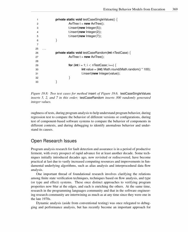
Extracting Behavior Models from Execution 369
1 private static void testCaseSingleValues() {2 AvlTree t = new AvlTree();3 t.insert(new Integer(5));4 t.insert(new Integer(2));5 t.insert(new Integer(7));6 }7
25 . . .26 private static void testCaseRandom(int nTestCase) {27 AvlTree t = new AvlTree();28
29 for (int i = 1; i < nTestCase; i++) {30 int value = (int) Math.round(Math.random() * 100);31 t.insert(new Integer(value));32 }33 }
Figure 19.8: Two test cases for method insert of Figure 19.6. testCaseSingleValuesinserts 5, 2, and 7 in this order; testCaseRandom inserts 300 randomly generatedinteger values.
oughness of tests, during program analysis to help understand program behavior, duringregression test to compare the behavior of different versions or configurations, duringtest of component-based software systems to compare the behavior of components indifferent contexts, and during debugging to identify anomalous behavior and under-stand its causes.
Open Research Issues
Program analysis research for fault detection and assurance is in a period of productiveferment, with every prospect of rapid advance for at least another decade. Some tech-niques initially introduced decades ago, now revisited or rediscovered, have becomepractical at last due to vastly increased computing resources and improvements in fun-damental underlying algorithms, such as alias analysis and interprocedural data flowanalysis.
One important thread of foundational research involves clarifying the relationsamong finite state verification techniques, techniques based on flow analysis, and type(or type and effect) systems. These once distinct approaches to verifying programproperties now blur at the edges, and each is enriching the others. At the same time,research in the programming languages community and that in the software engineer-ing research community are intertwining as much as at any time since they were one inthe late 1970s.
Dynamic analysis (aside from conventional testing) was once relegated to debug-ging and performance analysis, but has recently become an important approach for

370 Program Analysis
Behavior model for testCaseSingleValuesfather one of {2, 5, 7}left == 2right == 7leftHeight == rightHeightrightHeight == diffHeightleftHeight == 0rightHeight == 0fatherHeight one of {0, 1}
Behavior model for testCaseRandomfather >= 0left >= 0father > leftfather < rightleft < rightfatherHeight >= 0leftHeight >= 0rightHeight >= 0fatherHeight > leftHeightfatherHeight > rightHeightfatherHeight > diffHeightrightHeight >= diffHeightdiffHeight one of {−1,0,1}leftHeight - rightHeight + diffHeight == 0
Figure 19.9: The behavioral models for method insert of Figure 19.6. The modelwas obtained using Daikon with test cases testCaseSingleValues and testCaseRan-dom shown in Figure 19.8.

Extracting Behavior Models from Execution 371
constructing and refining models of program behavior. Synergistic combinations ofstatic program analysis, dynamic analysis, and testing are a promising avenue of fur-ther research.
Further Reading
Readings on some of the underlying techniques in program analysis are suggested inChapters 5, 6, 7, and 8. In addition, any good textbook on compiler construction willprovide useful basic background on extracting models from program source code.
A recent application of symbolic testing described by Bush, Pincus, and Sielaff[BPS00] is a good example of the revival of an approach that found little practicalapplication when first introduced in the 1970s. Aside from exploiting vastly greatercomputing capacity, the modern version of the technique improves on the original inseveral ways, most notably better managing communication of analysis results to theuser. Coen-Porisini et al. [CPDGP01] describe a modern application of symbolicexecution in constructing a rigorous demonstration of program properties by exploitinglimitations of an application domain.
Savage et al. [SBN+97] introduced the lockset analysis technique, which has in-fluenced a great deal of subsequent research in both static and dynamic analyses ofmulti-threaded software. The Daikon tool and its approach to behavioral model extrac-tion were introduced by Ernst et al. [ECGN01].
Exercises
19.1. We claimed that Java synchronized(l) { block } is easier to check statically thanseparate lock(l) and unlock(l) operations.
Give an example of how it could be harder to verify that lock(l) and unlock(l)operations protect a particular variable access than to verify that the access isprotected by a synchronized(l) { . . . }.
19.2. Although Java synchronized blocks make analysis of locking easy relative to in-dividual lock(l) and unlock(l) operations, it is still possible to construct Java pro-grams for which a static program analysis will not be able to determine whetheraccess at a particular program location is always protected by the same lock.Give an example of this, with an explanation. (Hint: Each lock in Java is identi-fied by a corresponding object.)
19.3. A fundamental facility for symbolic testing and many other static analysis tech-niques is to allow the user to note that a particular warning or error report isa false alarm, and to suppress it in future runs of the analysis tool. However,it is possible that a report that is a false alarm today might describe a real faultsometime later, due to program changes. How might you support the “revival” ofsuppressed error reports at appropriate times and points? Discuss the advantagesand disadvantages of your approach.
372 Program Analysis
19.4. Suppose we choose to model a program execution state with four pieces of in-formation — the program location (control point) and the states of four Booleanvariables w,x,y,and z — and suppose each of those variables is modeled by afinite state machine (FSM) with three states representing possible values (unini-tialized, true, and false).
If we were modeling just the possible values of w, a natural choice would be to la-bel each program location with an element from a powerset lattice in which eachlattice element represents a subset of automaton states. If we model w,x,y,and z,there are at least two different ways we could represent values at each programlocation: As a set of tuples of FSM states or as a tuple of sets of FSM states. Whatare the advantages and disadvantages of each of these representation choices?How might your choice depend on the property you were attempting to verify?
Part IV
Process
373


Chapter 20
Planning and Monitoring theProcess
Any complex process requires planning and monitoring. The quality process requirescoordination of many different activities over a period that spans a full developmentcycle and beyond. Planning is necessary to order, provision, and coordinate all theactivities that support a quality goal, and monitoring of actual status against a plan isrequired to steer and adjust the process.
Required Background
• Chapter 4Introduction of basic concepts of quality process, goals, and activities providesuseful background for understanding this chapter.
20.1 Overview
Planning involves scheduling activities, allocating resources, and devising observable,unambiguous milestones against which progress and performance can be monitored.Monitoring means answering the question, “How are we doing?”
Quality planning is one aspect of project planning, and quality processes must beclosely coordinated with other development processes. Coordination among qualityand development tasks may constrain ordering (e.g., unit tests are executed after cre-ation of program units). It may shape tasks to facilitate coordination; for example,delivery may be broken into smaller increments to allow early testing. Some aspects ofthe project plan, such as feedback and design for testability, may belong equally to thequality plan and other aspects of the project plan.
Quality planning begins at the inception of a project and is developed with theoverall project plan, instantiating and building on a quality strategy that spans severalprojects. Like the overall project plan, the quality plan is developed incrementally,beginning with the feasibility study and continuing through development and delivery.
375

376 Planning and Monitoring the Process
Formulation of the plan involves risk analysis and contingency planning. Execution ofthe plan involves monitoring, corrective action, and planning for subsequent releasesand projects.
Allocating responsibility among team members is a crucial and difficult part ofplanning. When one person plays multiple roles, explicitly identifying each responsi-bility is still essential for ensuring that none are neglected.
20.2 Quality and Process
A software plan involves many intertwined concerns, from schedule to cost to usabil-ity and dependability. Despite the intertwining, it is useful to distinguish individualconcerns and objectives to lessen the likelihood that they will be neglected, to allocateresponsibilities, and to make the overall planning process more manageable.
For example, a mature software project plan will include architectural design re-views, and the quality plan will allocate effort for reviewing testability aspects of thestructure and build order. Clearly, design for testability is an aspect of software designand cannot be carried out by a separate testing team in isolation. It involves both testdesigners and other software designers in explicitly evaluating testability as one consid-eration in selecting among design alternatives. The objective of incorporating designfor testability in the quality process is primarily to ensure that it is not overlooked andsecondarily to plan activities that address it as effectively as possible.
An appropriate quality process follows a form similar to the overall software pro-cess in which it is embedded. In a strict (and unrealistic) waterfall software process,one would follow the “V model” (Figure 2.1 on page 16) in a sequential manner, be-ginning unit testing only as implementation commenced following completion of thedetailed design phase, and finishing unit testing before integration testing commenced.In the XP “test first” method, unit testing is conflated with subsystem and system test-ing. A cycle of test design and test execution is wrapped around each small-grainincremental development step. The role that inspection and peer reviews would play inother processes is filled in XP largely by pair programming. A typical spiral processmodel lies somewhere between, with distinct planning, design, and implementationsteps in several increments coupled with a similar unfolding of analysis and test activi-ties. Some processes specifically designed around quality activities are briefly outlinedin the sidebars on pages 378, 380, and 381.
A general principle, across all software processes, is that the cost of detecting andrepairing a fault increases as a function of time between committing an error and detect-ing the resultant faults. Thus, whatever the intermediate work products in a softwareplan, an efficient quality plan will include a matched set of intermediate validation andverification activities that detect most faults within a short period of their introduction.Any step in a software process that is not paired with a validation or verification stepis an opportunity for defects to fester, and any milestone in a project plan that does notinclude a quality check is an opportunity for a misleading assessment of progress.
The particular verification or validation step at each stage depends on the natureof the intermediate work product and on the anticipated defects. For example, antic-ipated defects in a requirements statement might include incompleteness, ambiguity,
Test and Analysis Strategies 377
inconsistency, and overambition relative to project goals and resources. A review stepmight address some of these, and automated analyses might help with completenessand consistency checking.
The evolving collection of work products can be viewed as a set of descriptions ofdifferent parts and aspects of the software system, at different levels of detail. Portionsof the implementation have the useful property of being executable in a conventionalsense, and are the traditional subject of testing, but every level of specification anddesign can be both the subject of verification activities and a source of information forverifying other artifacts. A typical intermediate artifact — say, a subsystem interfacedefinition or a database schema — will be subject to the following steps:
Internal consistency check: Check the artifact for compliance with structuring rulesthat define “well-formed” artifacts of that type. An important point of leverageis defining the syntactic and semantic rules thoroughly and precisely enough thatmany common errors result in detectable violations. This is analogous to syn-tax and strong-typing rules in programming languages, which are not enough toguarantee program correctness but effectively guard against many simple errors.
External consistency check: Check the artifact for consistency with related artifacts.Often this means checking for conformance to a “prior” or “higher-level” speci-fication, but consistency checking does not depend on sequential, top-down de-velopment — all that is required is that the related information from two ormore artifacts be defined precisely enough to support detection of discrepancies.Consistency usually proceeds from broad, syntactic checks to more detailed andexpensive semantic checks, and a variety of automated and manual verificationtechniques may be applied.
Generation of correctness conjectures: Correctness conjectures, which can be testoutcomes or other objective criteria, lay the groundwork for external consistencychecks of other work products, particularly those that are yet to be developedor revised. Generating correctness conjectures for other work products will fre-quently motivate refinement of the current product. For example, an interfacedefinition may be elaborated and made more precise so that implementationscan be effectively tested.
20.3 Test and Analysis Strategies
Lessons of past experience are an important asset of organizations that rely heavilyon technical skills. A body of explicit knowledge, shared and refined by the group, ismore valuable than islands of individual competence. Organizational knowledge in ashared and systematic form is more amenable to improvement and less vulnerable toorganizational change, including the loss of key individuals. Capturing the lessons ofexperience in a consistent and repeatable form is essential for avoiding errors, main-taining consistency of the process, and increasing development efficiency.

378 Planning and Monitoring the Process
CleanroomThe Cleanroom process model, introduced by IBM in the late 1980s, pairs develop-
ment with V&V activities and stresses analysis over testing in the early phases. Testingis left for system certification. The Cleanroom process involves two cooperating teams,the development and the quality teams, and five major activities: specification, plan-ning, design and verification, quality certification, and feedback.
UsageFunction
Specification
Customer Requirements
Incremental Development
Planning
Formal DesignCorrectness Verification
Functional Specifications
Statistical Test-Case Generation
Usage Specifications
Statistical Testing
Source Code Test Cases
Quality Certification Model
Interfail Times
ImprovementFeedback
MTTF statistics
In the specification activity, the development team defines the required behaviorof the system, while the quality team defines usage scenarios that are later used forderiving system test suites. The planning activity identifies incremental developmentand certification phases.
After planning, all activities are iterated to produce incremental releases of the sys-tem. Each system increment is fully deployed and certified before the following step.Design and code undergo formal inspection (“Correctness verification”) before release.One of the key premises underpinning the Cleanroom process model is that rigorousdesign and formal inspection produce “nearly fault-free software.”
Usage profiles generated during specification are applied in the statistical testingactivity to gauge quality of each release. Another key assumption of the Cleanroomprocess model is that usage profiles are sufficiently accurate that statistical testing willprovide an accurate measure of quality as perceived by users.a Reliability is measuredin terms of mean time between failures (MTBF) and is constantly controlled after eachrelease. Failures are reported to the development team for correction, and if reliabilityfalls below an acceptable range, failure data is used for process improvement beforethe next incremental release.
aSee Chapter 22 for more detail on statistical testing and usage profiling.

Test and Analysis Strategies 379
Software organizations can develop useful, organization-specific strategies becauseof similarities among projects carried out by a particular organization in a set of relatedapplication domains. Test and analysis strategies capture commonalities across projectsand provide guidelines for maintaining consistency among quality plans.
A strategy is distinguished from a plan in that it is not specific to a single project.Rather, it provides guidance and a general framework for developing quality plans forseveral projects, satisfying organizational quality standards, promoting homogeneityacross projects, and making both the creation and execution of individual project qual-ity plans more efficient.
The quality strategy is an intellectual asset of an individual organization prescribinga set of solutions to problems specific to that organization. Among the factors thatparticularize the strategy are:
Structure and size: Large organizations typically have sharper distinctions betweendevelopment and quality groups, even if testing personnel are assigned to devel-opment teams. In smaller organizations, it is more common for a single person toserve multiple roles. Where responsibility is distributed among more individu-als, the quality strategy will require more elaborate attention to coordination andcommunication, and in general there will be much greater reliance on documentsto carry the collective memory.
In a smaller organization, or an organization that has devolved responsibility tosmall, semi-autonomous teams, there is typically less emphasis on formal com-munication and documents but a greater emphasis on managing and balancingthe multiple roles played by each team member.
Overall process: We have already noted the intertwining of quality process with otheraspects of an overall software process, and this is of course reflected in the qualitystrategy. For example, if an organization follows the Cleanroom methodology,then inspections will be required but unit testing forbidden. An organization thatadopts the XP methodology is likely to follow the “test first” and pair program-ming elements of that approach, and in fact would find a more document-heavyapproach a difficult fit.
Notations, standard process steps, and even tools can be reflected in the qualitystrategy to the extent they are consistent from project to project. For example,if an organization consistently uses a particular combination of UML diagramnotations to document subsystem interfaces, then the quality strategy might in-clude derivation of test designs from those notations, as well as review and anal-ysis steps tailored to detect the most common and important design flaws at thatpoint. If a particular version and configuration control system is woven intoprocess management, the quality strategy will likewise exploit it to support andenforce quality process steps.
Application domain: The domain may impose both particular quality objectives (e.g.,privacy and security in medical records processing), and in some cases particularsteps and documentation required to obtain certification from an external author-ity. For example, the RTCA/DO-178B standard for avionics software requirestesting to the modified condition/decision coverage (MC/DC) criterion.
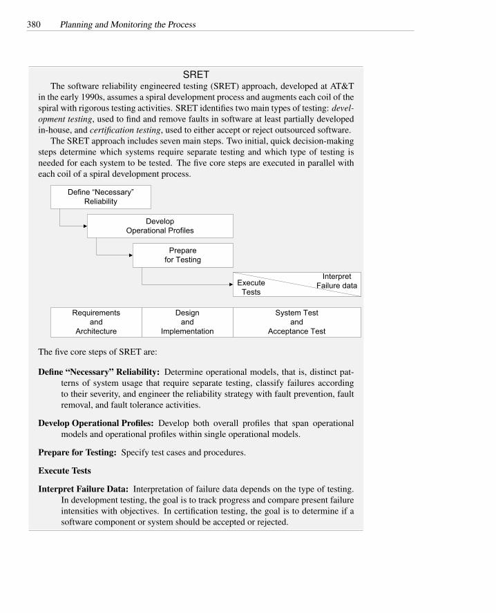
380 Planning and Monitoring the Process
SRETThe software reliability engineered testing (SRET) approach, developed at AT&T
in the early 1990s, assumes a spiral development process and augments each coil of thespiral with rigorous testing activities. SRET identifies two main types of testing: devel-opment testing, used to find and remove faults in software at least partially developedin-house, and certification testing, used to either accept or reject outsourced software.
The SRET approach includes seven main steps. Two initial, quick decision-makingsteps determine which systems require separate testing and which type of testing isneeded for each system to be tested. The five core steps are executed in parallel witheach coil of a spiral development process.
Define “Necessary”Reliability
DevelopOperational Profiles
Requirementsand
Architecture
Designand
Implementation
System Testand
Acceptance Test
Preparefor Testing
InterpretFailure dataExecute
Tests
The five core steps of SRET are:
Define “Necessary” Reliability: Determine operational models, that is, distinct pat-terns of system usage that require separate testing, classify failures accordingto their severity, and engineer the reliability strategy with fault prevention, faultremoval, and fault tolerance activities.
Develop Operational Profiles: Develop both overall profiles that span operationalmodels and operational profiles within single operational models.
Prepare for Testing: Specify test cases and procedures.
Execute Tests
Interpret Failure Data: Interpretation of failure data depends on the type of testing.In development testing, the goal is to track progress and compare present failureintensities with objectives. In certification testing, the goal is to determine if asoftware component or system should be accepted or rejected.

Test and Analysis Strategies 381
Extreme Programming (XP)The extreme programming methodology (XP) emphasizes simplicity over general-
ity, global vision and communication over structured organization, frequent changesover big releases, continuous testing and analysis over separation of roles and respon-sibilities, and continuous feedback over traditional planning.
Customer involvement in an XP project includes requirements analysis (develop-ment, refinement, and prioritization of user stories) and acceptance testing of veryfrequent iterative releases. Planning is based on prioritization of user stories, which areimplemented in short iterations. Test cases corresponding to scenarios in user storiesserve as partial specifications.
Generate User Stories
Create Unit Tests
Review, refine, prioritize
Pair Programming+ Unit testing
Passed all unit tests
Acceptance Testing
Passed allunit tests
Failed acceptance test
IncrementalRelease
Pass
Next version
Create Acceptance
Tests
Test cases suitable for batch execution are part of the system code base and are im-plemented prior to the implementation of features they check (“test-first”). Developerswork in pairs, incrementally developing and testing a module. Pair programming effec-tively conflates a review activity with coding. Each release is checked by running allthe tests devised up to that point of development, thus essentially merging unit testingwith integration and system testing. A failed acceptance test is viewed as an indicationthat additional unit tests are needed.
Although there are no standard templates for analysis and test strategies, we canidentify a few elements that should be part of almost any good strategy. A strategyshould specify common quality requirements that apply to all or most products, pro-moting conventions for unambiguously stating and measuring them, and reducing thelikelihood that they will be overlooked in the quality plan for a particular project. Astrategy should indicate a set of documents that is normally produced during the qualityprocess, and their contents and relationships. It should indicate the activities that areprescribed by the overall process organization. Often a set of standard tools and prac-tices will be prescribed, such as the interplay of a version and configuration controltool with review and testing procedures. In addition, a strategy includes guidelines forproject staffing and assignment of roles and responsibilities. An excerpt of a samplestrategy document is presented in Chapter 24.

382 Planning and Monitoring the Process
20.4 Test and Analysis Plans
An analysis and test plan details the steps to be taken in a particular project. A planshould answer the following questions:
• What quality activities will be carried out?
• What are the dependencies among the quality activities and between quality anddevelopment activities?
• What resources are needed and how will they be allocated?
• How will both the process and the evolving product be monitored to maintainan adequate assessment of quality and early warning of quality and scheduleproblems?
Each of these issues is addressed to some extent in the quality strategy, but mustbe elaborated and particularized. This is typically the responsibility of a quality man-ager, who should participate in the initial feasibility study to identify quality goals andestimate the contribution of test and analysis tasks on project cost and schedule.
To produce a quality plan that adequately addresses the questions above, the qualitymanager must identify the items and features to be verified, the resources and activitiesthat are required, the approaches that should be followed, and criteria for evaluatingthe results.
Items and features to be verified circumscribe the target of the quality plan. Whilethere is an obvious correspondence between items to be developed or modified andthose to undergo testing, they may differ somewhat in detail. For example, overallevaluation of the user interface may be the purview of a separate human factors group.The items to be verified, moreover, include many intermediate artifacts such as require-ments specifications and design documents, in addition to portions of the deliveredsystem. Approaches to be taken in verification and validation may vary among items.For example, the plan may prescribe inspection and testing for all items and additionalstatic analyses for multi-threaded subsystems.
Quality goals must be expressed in terms of properties satisfied by the product andmust be further elaborated with metrics that can be monitored during the course ofthe project. For example, if known failure scenarios are classified as critical, severe,moderate, and minor, then we might decide in advance that a product version mayenter end-user acceptance testing only when it has undergone system testing with nooutstanding critical or severe failures.
Defining quality objectives and process organization in detail requires informationthat is not all available in the early stages of development. Test items depend on de-sign decisions; detailed approaches to evaluation can be defined only after examiningrequirements and design specifications; tasks and schedule can be completed only afterthe design; new risks and contingencies may be introduced by decisions taken duringdevelopment. On the other hand, an early plan is necessary for estimating and control-ling cost and schedule. The quality manager must start with an initial plan based onincomplete and tentative information, and incrementally refine the plan as more andbetter information becomes available during the project.

Test and Analysis Plans 383
After capturing goals as well as possible, the next step in construction of a qualityplan is to produce an overall rough list of tasks. The quality strategy and past expe-rience provide a basis for customizing the list to the current project and for scalingtasks appropriately. For example, experience (preferably in the form of collected andanalyzed data from past projects, rather than personal memory) might suggest a ratioof 3:5 for person-months of effort devoted to integration test relative to coding effort.Historical data may also provide scaling factors for the application domain, interfaceswith externally developed software, and experience of the quality staff. To the extentpossible, the quality manager must break large tasks into component subtasks to ob-tain better estimates, but it is inevitable that some task breakdown must await furtherelaboration of the overall project design and schedule.
The manager can start noting dependencies among the quality activities and be-tween them and other activities in the overall project, and exploring arrangements oftasks over time. The main objective at this point is to schedule quality activities so thatassessment data are provided continuously throughout the project, without unneces-sary delay of other development activities. For example, the quality manager may notethat the design and implementation of different subsystems are scheduled in differentphases, and may plan subsystem testing accordingly.
Where there is a choice between scheduling a quality activity earlier or later, theearliest point possible is always preferable. However, the demand on resources (stafftime, primarily) must be leveled over time, and often one must carefully schedule theavailability of particular critical resources, such as an individual test designer with ex-pertise in a particular technology. Maintaining a consistent level of effort limits thenumber of activities that can be carried on concurrently, and resource constraints to-gether with the objective of minimizing project delays tends to force particular order-ings on tasks.
If one has a choice between completing two tasks in four months, or completingthe first task in two months and then the second in another two months, the schedulethat brings one task to completion earlier is generally advantageous from the perspec-tive of process visibility, as well as reduced coordination overhead. However, manyactivities demand a fraction of a person’s attention over a longer period and cannot becompressed. For example, participation in design and code inspection requires a sub-stantial investment of effort, but typically falls short of a full-time assignment. Sincedelayed inspections can be a bottleneck in progress of a project, they should have ahigh priority when they can be carried out, and are best interleaved with tasks that canbe more flexibly scheduled.
While the project plan shows the expected schedule of tasks, the arrangement andordering of tasks are also driven by risk. The quality plan, like the overall projectplan, should include an explicit risk plan that lists major risks and contingencies, asdiscussed in the next section.
A key tactic for controlling the impact of risk in the project schedule is to minimizethe likelihood that unexpected delay in one task propagates through the whole scheduleand delays project completion. One first identifies the critical paths through the projectschedule. Critical paths are chains of activities that must be completed in sequence andthat have maximum overall duration. Tasks on the critical path have a high priority critical paths
for early scheduling, and likewise the tasks on which they depend (which may not

384 Planning and Monitoring the Process
themselves be on the critical path) should be scheduled early enough to provide someschedule slack and prevent delay in the inception of the critical tasks.
A critical dependence occurs when a task on a critical path is scheduled immedi-ately after some other task on the critical path, particularly if the length of the criticalpath is close to the length of the project. Critical dependence may occur with taskscritical dependence
outside the quality plan part of the overall project plan.The primary tactic available for reducing the schedule risk of a critical dependence
is to decompose a task on the critical path, factoring out subtasks that can be performedearlier. For example, an acceptance test phase late in a project is likely to have a criticaldependence on development and system integration. One cannot entirely remove thisdependence, but its potential to delay project completion is reduced by factoring testdesign from test execution.
Figure 20.1 shows alternative schedules for a simple project that starts at the be-ginning of January and must be completed by the end of May. In the top schedule,indicated as CRITICAL SCHEDULE, the tasks Analysis and design, Code and Integra-tion, Design and execute subsystem tests, and Design and execute system tests form acritical path that spans the duration of the entire project. A delay in any of the activitieswill result in late delivery. In this schedule, only the Produce user documentation taskdoes not belong to the critical path, and thus only delays of this task can be tolerated.
In the middle schedule, marked as UNLIMITED RESOURCES, the test design andexecution activities are separated into distinct tasks. Test design tasks are scheduledearly, right after analysis and design, and only test execution is scheduled after Codeand integration. In this way the tasks Design subsystem tests and Design system testsare removed from the critical path, which now spans 16 weeks with a tolerance of 5weeks with respect to the expected termination of the project. This schedule assumesenough resources for running Code and integration, Production of user documentation,Design of subsystem tests, and Design of system tests.
The LIMITED RESOURCES schedule at the bottom of Figure 20.1 rearranges tasksto meet resource constraints. In this case we assume that test design and execution, andproduction of user documentation share the same resources and thus cannot be exe-cuted in parallel. We can see that, despite the limited parallelism, decomposing testingactivities and scheduling test design earlier results in a critical path of 17 weeks, 4weeks earlier than the expected termination of the project. Notice that in the example,the critical path is formed by the tasks Analysis and design, Design subsystem tests,Design system tests, Produce user documentation, Execute subsystem tests, and Exe-cute system tests. In fact, the limited availability of resources results in dependenciesamong Design subsystem tests, Design system tests and Produce user documentationthat last longer than the parallel task Code and integration.
The completed plan must include frequent milestones for assessing progress. Arule of thumb is that, for projects of a year or more, milestones for assessing progressshould occur at least every three months. For shorter projects, a reasonable maximuminterval for assessment is one quarter of project duration.
Figure 20.2 shows a possible schedule for the initial analysis and test plan for thebusiness logic of the Chipmunk Web presence in the form of a GANTT diagram. Inthe initial plan, the manager has allocated time and effort to inspections of all majorartifacts, as well as test design as early as practical and ongoing test execution dur-

Test and Analysis Plans 385
ID Task NameDec 2006 Jan 2007 Feb 2007 Mar 2007 Apr 2007
3 Analysis and design
4 Code and integration
5 Design and execute subsystem tests
6 Design and execute system tests
7 Produce user documentation
9 UNLIMITED RESOURCES
11 Analysis and design
12 Code and integration
13 Design subsystem tests
14 Design system tests
15 Produce user documentation
16 Execute subsystem tests
17 Execute system tests
19 LIMITED RESOURCES
21 Analysis and design
22 Code and integration
23 Design subsystem tests
24 Design system tests
25 Produce user documentation
26 Execute subystem tests
27 Execute system tests
2 Project start
8 Product delivery
Project start10
18 Product delivery
20 Project start
1 CRITICAL SCHEDULE
28 Product delivery
Figure 20.1: Three possible simple schedules with different risks and resource alloca-tion. The bars indicate the duration of the tasks. Diamonds indicate milestones, andarrows between bars indicate precedence between tasks.

386 Planning and Monitoring the Process
ing development. Division of the project into major parts is reflected in the plan, butfurther elaboration of tasks associated with units and smaller subsystems must awaitcorresponding elaboration of the architectural design. Thus, for example, inspectionof the shopping facilities code and the unit test suites is shown as a single aggregatetask. Even this initial plan does reflect the usual Chipmunk development strategy ofregular “synch and stabilize” periods punctuating development, and the initial qualityplan reflects the Chipmunk strategy of assigning responsibility for producing unit testsuites to developers, with review by a member of the quality team.
The GANTT diagram shows four main groups of analysis and test activities: de-sign inspection, code inspection, test design, and test execution. The distribution ofactivities over time is constrained by resources and dependence among activities. Forexample, system test execution starts after completion of system test design and cannotfinish before system integration (the sync and stablize elements of development frame-work) is complete. Inspection activities are constrained by specification and designactivities. Test design activities are constrained by limited resources. Late schedulingof the design of integration tests for the administrative business logic subsystem is nec-essary to avoid overlap with design of tests for the shopping functionality subsystem.
The GANTT diagram does not highlight intermediate milestones, but we can easilyidentify two in April and July, thus dividing the development into three main phases.The first phase (January to April) corresponds to requirements analysis and architec-tural design activities and terminates with the architectural design baseline. In thisphase, the quality team focuses on design inspection and on the design of acceptanceand system tests. The second phase (May to July) corresponds to subsystem design andto the implementation of the first complete version of the system. It terminates withthe first stabilization of the administrative business logic subsystem. In this phase, thequality team completes the design inspection and the design of test cases. In the finalstage, the development team produces the final version, while the quality team focuseson code inspection and test execution.
Absence of test design activities in the last phase results from careful identificationof activities that allowed early planning of critical tasks.
20.5 Risk Planning
Risk is an inevitable part of every project, and so risk planning must be a part of everyplan. Risks cannot be eliminated, but they can be assessed, controlled, and monitored.
The risk plan component of the quality plan is concerned primarily with personnelrisks, technology risks, and schedule risk. Personnel risk is any contingency that maymake a qualified staff member unavailable when needed. For example, the reassign-ment of a key test designer cannot always be avoided, but the possible consequencescan be analyzed in advance and minimized by careful organization of the work. Tech-nology risks in the quality plan include risks of technology used specifically by thequality team and risks of quality problems involving other technology used in the prod-uct or project. For example, changes in the target platform or in the testing environ-ment, due to new releases of the operating system or to the adoption of a new testingtool suite, may not be schedulable in advance, but may be taken into account in the

Risk Planning 387
IDTa
sk N
ame
1st q
uarte
r2n
d qu
arte
r3r
d qu
arte
r
1/7
2/4
1D
evel
opm
ent f
ram
ewor
k
2R
equi
rem
ents
spe
cific
atio
ns
3Ar
chite
ctur
al d
esig
n
4D
etai
led
desi
gn o
f sho
ppin
g fa
cilit
y su
bsys
.
5D
etai
led
desi
gn o
f ad
min
istra
tive
biz
logi
c
7Sy
nc a
nd s
tabi
lize
shop
ping
fa
c.
8Ad
min
biz
logi
c co
de a
nd
inte
grat
ion
(incl
udin
g un
it te
st)
9Sy
nc a
nd s
tabi
lize
adm
inis
trativ
e bi
z lo
gic
10D
esig
n in
spec
tion
11In
spec
tion
of re
quire
men
ts
spec
s.
12In
spec
tion
of a
rchi
tect
ural
de
sign
13In
spec
tion
of d
et. D
esig
n of
sh
op. f
acili
ties
14In
spec
tion
of d
etai
led
desi
gn
of a
dmin
logi
c15
Cod
e in
spec
tion
16In
spec
tion
of s
hop.
Fun
. Cor
e co
de a
nd u
nit t
ests
17In
spec
tion
of a
dmin
. Biz
. Log
. C
ode
code
and
uni
t tes
ts
18D
esig
n te
sts
19D
esig
n ac
cept
ance
test
s
20D
esig
n sy
stem
test
s
21D
esig
n sh
op fu
n su
bsys
tem
in
tegr
atio
n te
st
22D
esig
n ad
min
bix
log
subs
yste
m in
tegr
atio
n te
sts
23Te
st e
xecu
tion
24Ex
ec in
tegr
atio
n te
sts
25Ex
ec s
yste
m te
sts
26Ex
ec a
ccep
tanc
e te
sts
6Sh
oppi
ng fa
c co
de a
nd
inte
grat
ion
(incl
uni
t tes
t)
Figu
re20
.2:
Initi
alsc
hedu
lefo
rqu
ality
activ
ities
inde
velo
pmen
toft
hebu
sine
sslo
gic
subs
yste
mof
the
Chi
pmun
kW
ebpr
esen
ce,p
rese
nted
asa
GA
NTT
diag
ram
.

388 Planning and Monitoring the Process
organization of the testing environment. Schedule risk arises primarily from optimisticassumptions in the quality plan. For example, underestimating scaffolding design andmaintenance is a common mistake that cannot always be avoided, but consequencescan be mitigated (e.g., by allowing for a reasonable slack time that can absorb possibledelays). Many risks and the tactics for controlling them are generic to project manage-ment (e.g., cross-training to reduce the impact of losing a key staff member). Here wefocus on risks that are specific to quality planning or for which risk control measuresplay a special role in the quality plan.
The duration of integration, system, and acceptance test execution depends to alarge extent on the quality of software under test. Software that is sloppily constructedor that undergoes inadequate analysis and test before commitment to the code basewill slow testing progress. Even if responsibility for diagnosing test failures lies withdevelopers and not with the testing group, a test execution session that results in manyfailures and generates many failure reports is inherently more time consuming than exe-cuting a suite of tests with few or no failures. This schedule vulnerability is yet anotherreason to emphasize earlier activities, in particular those that provide early indicationsof quality problems. Inspection of design and code (with quality team participation)can help control this risk, and also serves to communicate quality standards and bestpractices among the team.
If unit testing is the responsibility of developers, test suites are part of the unit deliv-erable and should undergo inspection for correctness, thoroughness, and automation.While functional and structural coverage criteria are no panacea for measuring testthoroughness, it is reasonable to require that deviations from basic coverage criteria bejustified on a case-by-case basis. A substantial deviation from the structural coverageobserved in similar products may be due to many causes, including inadequate testing,incomplete specifications, unusual design, or implementation decisions. The modulesthat present unusually low structural coverage should be inspected to identify the cause.
The cost of analysis and test is multiplied when some requirements demand a veryhigh level of assurance. For example, if a system that has previously been used inbiological research is modified or redeveloped for clinical use, one should anticipatethat all development costs, and particularly costs of analysis and test, will be an orderof magnitude higher. In addition to the risk of underestimating the cost and sched-ule impact of stringent quality requirements, the risk of failing to achieve the requireddependability increases. One important tactic for controlling this risk is isolating crit-ical properties as far as possible in small, simple components. Of course these aspectsof system specification and architectural design are not entirely within control of thequality team; it is crucial that at least the quality manager, and possibly other mem-bers of the quality team, participate in specification and design activities to assess andcommunicate the impact of design alternatives on cost and schedule.
Architectural design is also the primary point of leverage to control cost and risks oftesting systems with complex external interfaces. For example, the hardware platformon which an embedded system must be tested may be a scarce resource, in demand fordebugging as well as testing. Preparing and executing a test case on that platform maybe time-consuming, magnifying the risk that system and operational testing may goover schedule and delay software delivery. This risk may be reduced by careful consid-eration of design-for-testability in architectural design. A testable design isolates and

Monitoring the Process 389
minimizes platform dependencies, reducing the portion of testing that requires accessto the platform. It will typically provide additional interfaces to enhance controllabil-ity and observability in testing. A considerable investment in test scaffolding, fromself-diagnosis to platform simulators, may also be warranted.
Risks related both to critical requirements and limitations on testability can be par-tially addressed in system specifications and programming standards. For example,it is notoriously difficult to detect race conditions by testing multi-threaded software.However, one may impose a design and programming discipline that prevents raceconditions, such as a simple monitor discipline with resource ordering. Detecting vi-olations of that discipline, statically and dynamically, is much simpler than detectingactual data races. This tactic may be reflected in several places in the project plan, fromsettling on the programming discipline in architectural design to checking for properuse of the discipline in code and design inspections, to implementation or purchase oftools to automate compliance checking.
The sidebars on page 390 and 391 summarize a set of risks both generic to processmanagement and specific to quality control that a quality manager must consider whendefining a quality plan.
20.6 Monitoring the Process
The quality manager monitors progress of quality activities, including results as well asschedule, to identify deviations from the quality plan as early as possible and take cor-rective action. Effective monitoring, naturally, depends on a plan that is realistic, wellorganized, and sufficiently detailed with clear, unambiguous milestones and criteria.We say a process is visible to the extent that it can be effectively monitored.
Successful completion of a planned activity must be distinguished from mere ter-mination, as otherwise it is too tempting to meet an impending deadline by omittingsome planned work. Skipping planned verification activities or addressing them su-perficially can seem to accelerate a late project, but the boost is only apparent; the realeffect is to postpone detection of more faults to later stages in development, where theirdetection and removal will be far more threatening to project success.
For example, suppose a developer is expected to deliver unit test cases as part of awork unit. If project deadlines are slipping, the developer is tempted to scrimp on de-signing unit tests and writing supporting code, perhaps dashing off a few superficial testcases so that the unit can be committed to the code base. The rushed development andinadequate unit testing are nearly guaranteed to leave bugs that surface later, perhapsin integration or system testing, where they will have a far greater impact on projectschedule. Worst of all, they might be first detected in operational use, reducing the realand perceived quality of the delivered product. In monitoring progress, therefore, itis essential to include appropriate metrics of the thoroughness or completeness of theactivity.
Monitoring produces a surfeit of detail about individual activities. Managers needto make decisions based on an overall understanding of project status, so raw monitor-ing information must be aggregated in ways that provide an overall picture.

390 Planning and Monitoring the Process
Risk Management in the Quality Plan: Risks Generic to Process ManagementThe quality plan must identify potential risks and define appropriate control tactics. Some risks
and control tactics are generic to process management, while others are specific to the quality process.Here we provide a brief overview of some risks generic to process management. Risks specific to thequality process are summarized in the sidebar on page 391.
Personnel Risks Example Control TacticsA staff member is lost (becomes ill, changes em-ployer, etc.) or is underqualified for task (theproject plan assumed a level of skill or familiar-ity that the assigned member did not have).
Cross train to avoid overdependence on individ-uals; encourage and schedule continuous educa-tion; provide open communication with oppor-tunities for staff self-assessment and identifica-tion of skills gaps early in the project; providecompetitive compensation and promotion poli-cies and a rewarding work environment to re-tain staff; include training time in the projectschedule.
Technology Risks Example Control TacticsMany faults are introduced interfacing to an un-familiar commercial off-the-shelf (COTS) com-ponent.
Anticipate and schedule extra time for testingunfamiliar interfaces; invest training time forCOTS components and for training with newtools; monitor, document, and publicize com-mon errors and correct idioms; introduce newtools in lower-risk pilot projects or prototypingexercises.
Test and analysis automation tools do not meetexpectations.
Introduce new tools in lower-risk pilot projectsor prototyping exercises; anticipate and scheduletime for training with new tools.
COTS components do not meet quality expecta-tions.
Include COTS component qualification testingearly in project plan; introduce new COTS com-ponents in lower-risk pilot projects or prototyp-ing exercises.
Schedule Risks Example Control TacticsInadequate unit testing leads to unanticipated ex-pense and delays in integration testing.
Track and reward quality unit testing as evi-denced by low-fault densities in integration.
Difficulty of scheduling meetings makes inspec-tion a bottleneck in development.
Set aside times in a weekly schedule in whichinspections take precedence over other meetingsand other work; try distributed and asynchronousinspection techniques, with a lower frequency offace-to-face inspection meetings.

Monitoring the Process 391
Risk Management in the Quality Plan: Risks Specific to Quality ManagementHere we provide a brief overview of some risks specific to the quality process. Risks generic to
process management are summarized in the sidebar at page 390.
Development Risks Example Control TacticsPoor quality software delivered to testing groupor inadequate unit test and analysis before com-mitting to the code base.
Provide early warning and feedback; scheduleinspection of design, code and test suites; con-nect development and inspection to the rewardsystem; increase training through inspection; re-quire coverage or other criteria at unit test level.
Executions Risks Example Control TacticsExecution costs higher than planned; scarce re-sources available for testing (testing requires ex-pensive or complex machines or systems not eas-ily available.)
Minimize parts that require full system to be exe-cuted; inspect architecture to assess and improvetestability; increase intermediate feedback; in-vest in scaffolding.
Requirements Risks Example Control TacticsHigh assurance critical requirements. Compare planned testing effort with former
projects with similar criticality level to avoidunderestimating testing effort; balance test andanalysis; isolate critical parts, concerns andproperties.
One key aggregate measure is the number of faults that have been revealed andremoved, which can be compared to data obtained from similar past projects. Faultdetection and removal can be tracked against time and will typically follow a charac-teristic distribution similar to that shown in Figure 20.3. The number of faults detectedper time unit tends to grow across several system builds, then to decrease at a muchlower rate (usually half the growth rate) until it stabilizes.
An unexpected pattern in fault detection may be a symptom of problems. If de-tected faults stop growing earlier than expected, one might hope it indicates exception-ally high quality, but it would be wise to consider the alternative hypothesis that faultdetection efforts are ineffective. A growth rate that remains high through more thanhalf the planned system builds is a warning that quality goals may be met late or not atall, and may indicate weaknesses in fault removal or lack of discipline in development(e.g., a rush to add features before delivery, with a consequent deemphasis on qualitycontrol).
A second indicator of problems in the quality process is faults that remain openlonger than expected. Quality problems are confirmed when the number of open faultsdoes not stabilize at a level acceptable to stakeholders.
The accuracy with which we can predict fault data and diagnose deviations fromexpectation depends on the stability of the software development and quality processes,and on availability of data from similar projects. Differences between organizationsand across application domains are wide, so by far the most valuable data is from
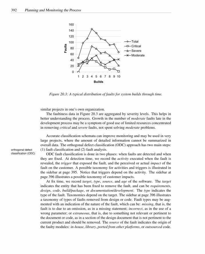
392 Planning and Monitoring the Process
0
20
40
60
80
100
120
140
160
1 2 3 4 5 6 7 8 9 10
Builds
Faults
TotalCriticalSevereModerate
Figure 20.3: A typical distribution of faults for system builds through time.
similar projects in one’s own organization.The faultiness data in Figure 20.3 are aggregated by severity levels. This helps in
better understanding the process. Growth in the number of moderate faults late in thedevelopment process may be a symptom of good use of limited resources concentratedin removing critical and severe faults, not spent solving moderate problems.
Accurate classification schemata can improve monitoring and may be used in verylarge projects, where the amount of detailed information cannot be summarized inoverall data. The orthogonal defect classification (ODC) approach has two main steps:(1) fault classification and (2) fault analysis.orthogonal defect
classification (ODC) ODC fault classification is done in two phases: when faults are detected and whenthey are fixed. At detection time, we record the activity executed when the fault isrevealed, the trigger that exposed the fault, and the perceived or actual impact of thefault on the customer. A possible taxonomy for activities and triggers is illustrated inthe sidebar at page 395. Notice that triggers depend on the activity. The sidebar atpage 396 illustrates a possible taxonomy of customer impacts.
At fix time, we record target, type, source, and age of the software. The targetindicates the entity that has been fixed to remove the fault, and can be requirements,design, code, build/package, or documentation/development. The type indicates thetype of the fault. Taxonomies depend on the target. The sidebar at page 396 illustratesa taxonomy of types of faults removed from design or code. Fault types may be aug-mented with an indication of the nature of the fault, which can be: missing, that is, thefault is to due to an omission, as in a missing statement; incorrect, as in the use of awrong parameter; or extraneous, that is, due to something not relevant or pertinent tothe document or code, as in a section of the design document that is not pertinent to thecurrent product and should be removed. The source of the fault indicates the origin ofthe faulty modules: in-house, library, ported from other platforms, or outsourced code.

Monitoring the Process 393
The age indicates the age of the faulty element — whether the fault was found in new,old (base), rewritten, or re-fixed code.
The detailed information on faults allows for many analyses that can provide in-formation on the development and the quality process. As in the case of analysis ofsimple faultiness data, the interpretation depends on the process and the product, andshould be based on past experience. The taxonomy of faults, as well as the analysis offaultiness data, should be refined while applying the method.
When we first apply the ODC method, we can perform some preliminary analysisusing only part of the collected information:
Distribution of fault types versus activities: Different quality activities target differ-ent classes of faults. For example, algorithmic (that is, local) faults are targetedprimarily by unit testing, and we expect a high proportion of faults detected byunit testing to be in this class. If the proportion of algorithmic faults found duringunit testing is unusually small, or a larger than normal proportion of algorithmicfaults are found during integration testing, then one may reasonably suspect thatunit tests have not been well designed. If the mix of faults found during inte-gration testing contains an unusually high proportion of algorithmic faults, it isalso possible that integration testing has not focused strongly enough on interfacefaults.
Distribution of triggers over time during field test: Faults corresponding to simpleusage should arise early during field test, while faults corresponding to complexusage should arise late. In both cases, the rate of disclosure of new faults shouldasymptotically decrease. Unexpected distributions of triggers over time mayindicate poor system or acceptance test. If triggers that correspond to simpleusage reveal many faults late in acceptance testing, we may have chosen a samplethat is not representative of the user population. If faults continue growing duringacceptance test, system testing may have failed, and we may decide to resume itbefore continuing with acceptance testing.
Age distribution over target code: Most faults should be located in new and rewrit-ten code, while few faults should be found in base or re-fixed code, since base andre-fixed code has already been tested and corrected. Moreover, the proportion offaults in new and rewritten code with respect to base and re-fixed code shouldgradually increase. Different patterns may indicate holes in the fault tracking andremoval process or may be a symptom of inadequate test and analysis that failedin revealing faults early (in previous tests of base or re-fixed code). For example,an increase of faults located in base code after porting to a new platform mayindicate inadequate tests for portability.
Distribution of fault classes over time: The proportion of missing code faults shouldgradually decrease, while the percentage of extraneous faults may slowly in-crease, because missing functionality should be revealed with use and repaired,while extraneous code or documentation may be produced by updates. An in-creasing number of missing faults may be a symptom of instability of the prod-uct, while a sudden sharp increase in extraneous faults may indicate maintenanceproblems.

394 Planning and Monitoring the Process
20.7 Improving the Process
Many classes of faults that occur frequently are rooted in process and developmentflaws. For example, a shallow architectural design that does not take into accountresource allocation can lead to resource allocation faults. Lack of experience withthe development environment, which leads to misunderstandings between analysts andprogrammers on rare and exceptional cases, can result in faults in exception handling.A performance assessment system that rewards faster coding without regard to qualityis likely to promote low quality code.
The occurrence of many such faults can be reduced by modifying the process andenvironment. For example, resource allocation faults resulting from shallow architec-tural design can be reduced by introducing specific inspection tasks. Faults attributableto inexperience with the development environment can be reduced with focused train-ing sessions. Persistently poor programming practices may require modification of thereward system.
Often, focused changes in the process can lead to product improvement and signif-icant cost reduction. Unfortunately, identifying the weak aspects of a process can beextremely difficult, and often the results of process analysis surprise even expert man-agers. The analysis of the fault history can help software engineers build a feedbackmechanism to track relevant faults to their root causes, thus providing vital informa-tion for improving the process. In some cases, information can be fed back directlyinto the current product development, but more often it helps software engineers im-prove the development of future products. For example, if analysis of faults revealsfrequent occurrence of severe memory management faults in C programs, we mightrevise inspection checklists and introduce dynamic analysis tools, but it may be toolate to change early design decisions or select a different programming language in theproject underway. More fundamental changes may be made in future projects.
Root cause analysis (RCA) is a technique for identifying and eliminating processfaults. RCA was first developed in the nuclear power industry and later extended tosoftware analysis. It consists of four main steps to select significant classes of faults∆ root cause
analysis and track them back to their original causes: What, When, Why, and How.
What are the faults? The goal of this first step is to identify a class of importantfaults. Faults are categorized by severity and kind. The severity of faults characterizesthe impact of the fault on the product. Although different methodologies use slightlydifferent scales and terms, all of them identify a few standard levels, described in Ta-ble 20.1.
The RCA approach to categorizing faults, in contrast to ODC, does not use a pre-defined set of categories. The objective of RCA is not to compare different classes offaults over time, or to analyze and eliminate all possible faults, but rather to identify thefew most important classes of faults and remove their causes. Successful application ofRCA progressively eliminates the causes of the currently most important faults, whichlose importance over time, so applying a static predefined classification would be use-less. Moreover, the precision with which we identify faults depends on the specificproject and process and varies over time.

Improving the Process 395
ODC Classification of Triggers Listed by Activity
Design Review and Code Inspection
Design Conformance A discrepancy between the reviewed artifact and a prior-stage artifactthat serves as its specification.
Logic/Flow An algorithmic or logic flaw.
Backward Compatibility A difference between the current and earlier versions of an artifactthat could be perceived by the customer as a failure.
Internal Document An internal inconsistency in the artifact (e.g., inconsistency between codeand comments).
Lateral Compatibility An incompatibility between the artifact and some other system or mod-ule with which it should interoperate.
Concurrency A fault in interaction of concurrent processes or threads.
Language Dependency A violation of language-specific rules, standards, or best practices.
Side Effects A potential undesired interaction between the reviewed artifact and some other partof the system.
Rare Situation An inappropriate response to a situation that is not anticipated in the artifact.(Error handling as specified in a prior artifact design conformance, not rare situation.)
Structural (White-Box) Test
Simple Path The fault is detected by a test case derived to cover a single program element.
Complex Path The fault is detected by a test case derived to cover a combination of programelements.
Functional (Black-Box) Test
Coverage The fault is detected by a test case derived for testing a single procedure (e.g., C func-tion or Java method), without considering combination of values for possible parameters.
Variation The fault is detected by a test case derived to exercise a particular combination ofparameters for a single procedure.
Sequencing The fault is detected by a test case derived for testing a sequence of procedure calls.
Interaction The fault is detected by a test case derived for testing procedure interactions.
System Test
Workload/Stress The fault is detected during workload or stress testing.
Recovery/Exception The fault is detected while testing exceptions and recovery procedures.
Startup/Restart The fault is detected while testing initialization conditions during start up orafter possibly faulty shutdowns.
Hardware Configuration The fault is detected while testing specific hardware configurations.
Software Configuration The fault is detected while testing specific software configurations.
Blocked Test Failure occurred in setting up the test scenario.

396 Planning and Monitoring the Process
ODC Classification of Customer ImpactInstallability Ability of the customer to place the software into actual use. (Usability of the
installed software is not included.)
Integrity/Security Protection of programs and data from either accidental or malicious destruc-tion or alteration, and from unauthorized disclosure.
Performance The perceived and actual impact of the software on the time required for thecustomer and customer end users to complete their tasks.
Maintenance The ability to correct, adapt, or enhance the software system quickly and at min-imal cost.
Serviceability Timely detection and diagnosis of failures, with minimal customer impact.
Migration Ease of upgrading to a new system release with minimal disruption to existing cus-tomer data and operations.
Documentation Degree to which provided documents (in all forms, including electronic) com-pletely and correctly describe the structure and intended uses of the software.
Usability The degree to which the software and accompanying documents can be understoodand effectively employed by the end user.
Standards The degree to which the software complies with applicable standards.
Reliability The ability of the software to perform its intended function without unplanned in-terruption or failure.
Accessibility The degree to which persons with disabilities can obtain the full benefit of thesoftware system.
Capability The degree to which the software performs its intended functions consistently withdocumented system requirements.
Requirements The degree to which the system, in complying with document requirements,actually meets customer expectations
ODC Classification of Defect Types for Targets Design and CodeAssignment/Initialization A variable was not assigned the correct initial value or was not as-
signed any initial value.
Checking Procedure parameters or variables were not properly validated before use.
Algorithm/Method A correctness or efficiency problem that can be fixed by reimplementing asingle procedure or local data structure, without a design change.
Function/Class/Object A change to the documented design is required to conform to productrequirements or interface specifications.
Timing/Synchronization The implementation omits necessary synchronization of shared re-sources, or violates the prescribed synchronization protocol.
Interface/Object-Oriented Messages Module interfaces are incompatible; this can includesyntactically compatible interfaces that differ in semantic interpretation of communicateddata.
Relationship Potentially problematic interactions among procedures, possibly involving differ-ent assumptions but not involving interface incompatibility.
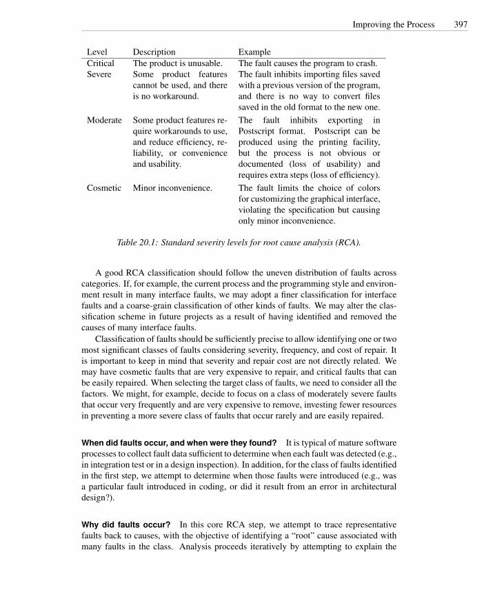
Improving the Process 397
Level Description ExampleCritical The product is unusable. The fault causes the program to crash.Severe Some product features
cannot be used, and thereis no workaround.
The fault inhibits importing files savedwith a previous version of the program,and there is no way to convert filessaved in the old format to the new one.
Moderate Some product features re-quire workarounds to use,and reduce efficiency, re-liability, or convenienceand usability.
The fault inhibits exporting inPostscript format. Postscript can beproduced using the printing facility,but the process is not obvious ordocumented (loss of usability) andrequires extra steps (loss of efficiency).
Cosmetic Minor inconvenience. The fault limits the choice of colorsfor customizing the graphical interface,violating the specification but causingonly minor inconvenience.
Table 20.1: Standard severity levels for root cause analysis (RCA).
A good RCA classification should follow the uneven distribution of faults acrosscategories. If, for example, the current process and the programming style and environ-ment result in many interface faults, we may adopt a finer classification for interfacefaults and a coarse-grain classification of other kinds of faults. We may alter the clas-sification scheme in future projects as a result of having identified and removed thecauses of many interface faults.
Classification of faults should be sufficiently precise to allow identifying one or twomost significant classes of faults considering severity, frequency, and cost of repair. Itis important to keep in mind that severity and repair cost are not directly related. Wemay have cosmetic faults that are very expensive to repair, and critical faults that canbe easily repaired. When selecting the target class of faults, we need to consider all thefactors. We might, for example, decide to focus on a class of moderately severe faultsthat occur very frequently and are very expensive to remove, investing fewer resourcesin preventing a more severe class of faults that occur rarely and are easily repaired.
When did faults occur, and when were they found? It is typical of mature softwareprocesses to collect fault data sufficient to determine when each fault was detected (e.g.,in integration test or in a design inspection). In addition, for the class of faults identifiedin the first step, we attempt to determine when those faults were introduced (e.g., wasa particular fault introduced in coding, or did it result from an error in architecturaldesign?).
Why did faults occur? In this core RCA step, we attempt to trace representativefaults back to causes, with the objective of identifying a “root” cause associated withmany faults in the class. Analysis proceeds iteratively by attempting to explain the
398 Planning and Monitoring the Process
The 80/20 or Pareto RuleFault classification in root cause analysis is justified by the so-called 80/20 or Pareto
rule. The Pareto rule is named for the Italian economist Vilfredo Pareto, who in theearly nineteenth century proposed a mathematical power law formula to describe theunequal distribution of wealth in his country, observing that 20% of the people owned80% of the wealth.
Pareto observed that in many populations, a few (20%) are vital and many (80%) aretrivial. In fault analysis, the Pareto rule postulates that 20% of the code is responsiblefor 80% of the faults. Although proportions may vary, the rule captures two importantfacts:
1. Faults tend to accumulate in a few modules, so identifying potentially faultymodules can improve the cost effectiveness of fault detection.
2. Some classes of faults predominate, so removing the causes of a predominantclass of faults can have a major impact on the quality of the process and of theresulting product.
The predominance of a few classes of faults justifies focusing on one class at a time.
error that led to the fault, then the cause of that error, the cause of that cause, and soon. The rule of thumb “ask why six times” does not provide a precise stopping rule forthe analysis, but suggests that several steps may be needed to find a cause in commonamong a large fraction of the fault class under consideration.
Tracing the causes of faults requires experience, judgment, and knowledge of thedevelopment process. We illustrate with a simple example. Imagine that the first RCAstep identified memory leaks as the most significant class of faults, combining a mod-erate frequency of occurrence with severe impact and high cost to diagnose and repair.The group carrying out RCA will try to identify the cause of memory leaks and mayconclude that many of them result from forgetting to release memory in exception han-dlers. The RCA group may trace this problem in exception handling to lack of infor-mation: Programmers can’t easily determine what needs to be cleaned up in exceptionhandlers. The RCA group will ask why once more and may go back to a design error:The resource management scheme assumes normal flow of control and thus does notprovide enough information to guide implementation of exception handlers. Finally,the RCA group may identify the root problem in an early design problem: Exceptionalconditions were an afterthought dealt with late in design.
Each step requires information about the class of faults and about the developmentprocess that can be acquired through inspection of the documentation and interviewswith developers and testers, but the key to success is curious probing through severallevels of cause and effect.
How could faults be prevented? The final step of RCA is improving the process byremoving root causes or making early detection likely. The measures taken may have

The Quality Team 399
a minor impact on the development process (e.g., adding consideration of exceptionalconditions to a design inspection checklist), or may involve a substantial modificationof the process (e.g., making explicit consideration of exceptional conditions a part of allrequirements analysis and design steps). As in tracing causes, prescribing preventativeor detection measures requires judgment, keeping in mind that the goal is not perfectionbut cost-effective improvement.
ODC and RCA are two examples of feedback and improvement, which are an im-portant dimension of most good software processes. Explicit process improvementsteps are, for example, featured in both SRET (sidebar on page 380) and Cleanroom(sidebar on page 378).
20.8 The Quality Team
The quality plan must assign roles and responsibilities to people. As with other aspectsof planning, assignment of responsibility occurs at a strategic level and a tactical level.The tactical level, represented directly in the project plan, assigns responsibility to in-dividuals in accordance with the general strategy. It involves balancing level of effortacross time and carefully managing personal interactions. The strategic level of orga-nization is represented not only in the quality strategy document, but in the structure ofthe organization itself.
The strategy for assigning responsibility may be partly driven by external require-ments. For example, independent quality teams may be required by certification agen-cies or by a client organization. Additional objectives include ensuring sufficient ac-countability that quality tasks are not easily overlooked; encouraging objective judg-ment of quality and preventing it from being subverted by schedule pressure; fosteringshared commitment to quality among all team members; and developing and commu-nicating shared knowledge and values regarding quality.
Measures taken to attain some objectives (e.g., autonomy to ensure objective as-sessment) are in tension with others (e.g., cooperation to meet overall project objec-tives). It is therefore not surprising to find that different organizations structure rolesand responsibilities in a wide variety of different ways. The same individuals can playthe roles of developer and tester, or most testing responsibility can be assigned to mem-bers of a distinct group, and some may even be assigned to a distinct organization ona contractual basis. Oversight and accountability for approving the work product of atask are sometimes distinguished from responsibility for actually performing a task, sothe team organization is somewhat intertwined with the task breakdown.
Each of the possible organizations of quality roles makes some objectives easierto achieve and some more challenging. Conflict of one kind or another is inevitable,and therefore in organizing the team it is important to recognize the conflicts and takemeasures to control adverse consequences. If an individual plays two roles in potentialconflict (e.g., a developer responsible for delivering a unit on schedule is also respon-sible for integration testing that could reveal faults that delay delivery), there must becountermeasures to control the risks inherent in that conflict. If roles are assigned todifferent individuals, then the corresponding risk is conflict between the individuals

400 Planning and Monitoring the Process
(e.g., if a developer and a tester do not adequately share motivation to deliver a qualityproduct on schedule).
An independent and autonomous testing team lies at one end of the spectrum ofpossible team organizations. One can make that team organizationally independentso that, for example, a project manager with schedule pressures can neither bypassquality activities or standards, nor reallocate people from testing to development, norpostpone quality activities until too late in the project. Separating quality roles fromdevelopment roles minimizes the risk of conflict between roles played by an individual,and thus makes most sense for roles in which independence is paramount, such as finalsystem and acceptance testing. An independent team devoted to quality activities alsohas an advantage in building specific expertise, such as test design. The primary riskarising from separation is in conflict between goals of the independent quality teamand the developers.
When quality tasks are distributed among groups or organizations, the plan shouldinclude specific checks to ensure successful completion of quality activities. For ex-ample, when module testing is performed by developers and integration and systemtesting is performed by an independent quality team, the quality team should check thecompleteness of module tests performed by developers, for example, by requiring sat-isfaction of coverage criteria or inspecting module test suites. If testing is performed byan independent organization under contract, the contract should carefully describe thetesting process and its results and documentation, and the client organization shouldverify satisfactory completion of the contracted tasks.
Existence of a testing team must not be perceived as relieving developers from re-sponsibility for quality, nor is it healthy for the testing team to be completely obliviousto other pressures, including schedule pressure. The testing team and developmentteam, if separate, must at least share the goal of shipping a high-quality product onschedule.
Independent quality teams require a mature development process to minimize com-munication and coordination overhead. Test designers must be able to work on suffi-ciently precise specifications and must be able to execute tests in a controllable testenvironment. Versions and configurations must be well defined, and failures and faultsmust be suitably tracked and monitored across versions.
It may be logistically impossible to maintain an independent quality group, espe-cially in small projects and organizations, where flexibility in assignments is essentialfor resource management. Aside from the logistical issues, division of responsibilitycreates additional work in communication and coordination. Finally, quality activitiesoften demand deep knowledge of the project, particularly at detailed levels (e.g., unitand early integration test). An outsider will have less insight into how and what totest, and may be unable to effectively carry out the crucial earlier activities, such asestablishing acceptance criteria and reviewing architectural design for testability. Forall these reasons, even organizations that rely on an independent verification and val-idation (IV&V) group for final product qualification allocate other responsibilities todevelopers and to quality professionals working more closely with the developmentteam.
At the polar opposite from a completely independent quality team is full integra-tion of quality activities with development, as in some “agile” processes including XP.

The Quality Team 401
Communication and coordination overhead is minimized this way, and developers takefull responsibility for the quality of their work product. Moreover, technology and ap-plication expertise for quality tasks will match the expertise available for developmenttasks, although the developer may have less specific expertise in skills such as testdesign.
The more development and quality roles are combined and intermixed, the moreimportant it is to build into the plan checks and balances to be certain that qualityactivities and objective assessment are not easily tossed aside as deadlines loom. Forexample, XP practices like “test first” together with pair programming (sidebar on page381) guard against some of the inherent risks of mixing roles.
Separate roles do not necessarily imply segregation of quality activities to distinctindividuals. It is possible to assign both development and quality responsibility to de-velopers, but assign two individuals distinct responsibilities for each development workproduct. Peer review is an example of mixing roles while maintaining independenceon an item-by-item basis. It is also possible for developers and testers to participatetogether in some activities.
Many variations and hybrid models of organization can be designed. Some orga-nizations have obtained a good balance of benefits by rotating responsibilities. Forexample, a developer may move into a role primarily responsible for quality in oneproject and move back into a regular development role in the next. In organizationslarge enough to have a distinct quality or testing group, an appropriate balance betweenindependence and integration typically varies across levels of project organization. Atsome levels, an appropriate balance can be struck by giving responsibility for an ac-tivity (e.g., unit testing) to developers who know the code best, but with a separateoversight responsibility shared by members of the quality team. For example, unit testsmay be designed and implemented by developers, but reviewed by a member of thequality team for effective automation (particularly, suitability for automated regressiontest execution as the product evolves) as well as thoroughness. The balance tips furthertoward independence at higher levels of granularity, such as in system and acceptancetesting, where at least some tests should be designed independently by members of thequality team.
Outsourcing test and analysis activities is sometimes motivated by the perceptionthat testing is less technically demanding than development and can be carried out bylower-paid and lower-skilled individuals. This confuses test execution, which should infact be straightforward, with analysis and test design, which are as demanding as designand programming tasks in development. Of course, less skilled individuals can designand carry out tests, just as less skilled individuals can design and write programs, butin both cases the results are unlikely to be satisfactory.
Outsourcing can be a reasonable approach when its objectives are not merely min-imizing cost, but maximizing independence. For example, an independent judgmentof quality may be particularly valuable for final system and acceptance testing, andmay be essential for measuring a product against an independent quality standard (e.g.,qualifying a product for medical or avionic use). Just as an organization with mixedroles requires special attention to avoid the conflicts between roles played by an indi-vidual, radical separation of responsibility requires special attention to control conflicts

402 Planning and Monitoring the Process
between the quality assessment team and the development team.The plan must clearly define milestones and delivery for outsourced activities, as
well as checks on the quality of delivery in both directions: Test organizations usuallyperform quick checks to verify the consistency of the software to be tested with respectto some minimal “testability” requirements; clients usually check the completeness andconsistency of test results. For example, test organizations may ask for the results ofinspections on the delivered artifact before they start testing, and may include somequick tests to verify the installability and testability of the artifact. Clients may checkthat tests satisfy specified functional and structural coverage criteria, and may inspectthe test documentation to check its quality. Although the contract should detail therelation between the development and the testing groups, ultimately, outsourcing relieson mutual trust between organizations.
Open Research Issues
Orthogonal defect classification (introduced in the 1990s) and root cause analysis (in-troduced in the 1980s) remain key techniques for deriving useful guidance from expe-rience. Considering widespread agreement on the importance of continuous processimprovement, we should expect innovation and adaptation of these key techniques forcurrent conditions. An example is the renewed interest in fault-proneness models, ex-ploiting the rich historical data available in version control systems and bug trackingdatabases.
Globally distributed software teams and teams that span multiple companies andorganizations pose many interesting challenges for software development in generaland test and analysis in particular. We expect that both technical and managementinnovations will adapt to these important trends, with increasing interplay betweenresearch in software test and analysis and research in computer-supported collaborativework (CSCW).
Further Reading
IEEE publishes a standard for software quality assurance plans [Ins02], which servesas a good starting point. The plan outline in this chapter is based loosely on the IEEEstandard. Jaaksi [Jaa03] provides a useful discussion of decision making based on dis-tribution of fault discovery and resolution over the course of a project, drawn fromexperience at Nokia. Chaar et al. [CHBC93] describe the orthogonal defect clas-sification technique, and Bhandari et al. [BHC+94] provide practical details useful inimplementing it. Leszak et al. [LPS02] describe a retrospective process with root causeanalysis, process compliance analysis, and software complexity analysis. Denaro andPezze [DP02] describe fault-proneness models for allocating effort in a test plan. De-Marco and Lister [DL99] is a popular guide to the human dimensions of managingsoftware teams.
The Quality Team 403
Exercises
20.1. Testing compatibility with a variety of device drivers is a significant cost andschedule factor in some projects. For example, a well-known developer of desk-top publishing software maintains a test laboratory containing dozens of currentand outdated models of Macintosh computer, running several operating systemversions.
Put yourself in the place of the quality manager for a new version of this desktoppublishing software, and consider in particular the printing subsystem of thesoftware package. Your goal is to minimize the schedule impact of testing thesoftware against a large number of printers, and in particular to reduce the riskthat serious problems in the printing subsystem surface late in the project, or thattesting on the actual hardware delays product release.
How can the software architectural design be organized to serve your goals ofreducing cost and risk? Do you expect your needs in this regard will be alignedwith those of the development manager, or in conflict? What other measuresmight you take in project planning, and in particular in the project schedule, tominimize risks of problems arising when the software is tested in an operationalenvironment? Be as specific as possible, and avoid simply restating the generalstrategies presented in this chapter.
20.2. Chipmunk Computers has signed an agreement with a software house for soft-ware development under contract. Project leaders are encouraged to take advan-tage of this agreement to outsource development of some modules and therebyreduce project cost. Your project manager asks you to analyze the risks thatmay result from this choice and propose approaches to reduce the impact of theidentified risks. What would you suggest?
20.3. Suppose a project applied orthogonal defect classification and analyzed corre-lation between fault types and fault triggers, as well as between fault types andimpact. What useful information could be derived from cross-correlating thoseclassifications, beyond the information available from each classification alone?
20.4. ODC attributes have been adapted and extended in several ways, one of which isincluding fault qualifier, which distinguishes whether the fault is due to missing,incorrect, or extraneous code. What attributes might fault qualifier be correlatedwith, and what useful information might thereby be obtained?

404 Planning and Monitoring the Process

Chapter 21
Integration andComponent-basedSoftware Testing
Problems arise in integration even of well-designed modules and components. Integra-tion testing aims to uncover interaction and compatibility problems as early as possible.This chapter presents integration testing strategies, including the increasingly impor-tant problem of testing integration with commercial off-the-shelf (COTS) components,libraries, and frameworks.
Required Background
• Chapter 4Basic concepts of quality process, goals, and activities are important for under-standing this chapter.
• Chapter 17Scaffolding is a key cost element of integration testing. Some knowledge aboutscaffolding design and implementation is important to fully understand an essen-tial dimension of integration testing.
21.1 Overview
The traditional V model introduced in Chapter 2 divides testing into four main levelsof granularity: module, integration, system, and acceptance test. Module or unit testchecks module behavior against specifications or expectations; integration test checksmodule compatibility; system and acceptance tests check behavior of the whole systemwith respect to specifications and user needs, respectively.
An effective integration test is built on a foundation of thorough module testing andinspection. Module test maximizes controllability and observability of an individual
405
406 Integration and Component-based Software Testing
unit, and is more effective in exercising the full range of module behaviors, rather thanjust those that are easy to trigger and observe in a particular context of other modules.While integration testing may to some extent act as a process check on module testing(i.e., faults revealed during integration test can be taken as a signal of unsatisfactoryunit testing), thorough integration testing cannot fully compensate for sloppiness at themodule level. In fact, the quality of a system is limited by the quality of the modulesand components from which it is built, and even apparently noncritical modules canhave widespread effects. For example, in 2004 a buffer overflow vulnerability in asingle, widely used library for reading Portable Network Graphics (PNG) files causedsecurity vulnerabilities in Windows, Linux, and Mac OS X Web browsers and emailclients.
On the other hand, some unintended side-effects of module faults may becomeapparent only in integration test (see sidebar on page 409), and even a module thatsatisfies its interface specification may be incompatible because of errors introducedin design decomposition. Integration tests therefore focus on checking compatibilitybetween module interfaces.
Integration faults are ultimately caused by incomplete specifications or faulty im-plementations of interfaces, resource usage, or required properties. Unfortunately, itmay be difficult or not cost-effective to anticipate and completely specify all moduleinteractions. For example, it may be very difficult to anticipate interactions betweenremote and apparently unrelated modules through sharing a temporary hidden file thatjust happens to be given the same name by two modules, particularly if the name clashappears rarely and only in some installation configurations. Some of the possible man-ifestations of incomplete specifications and faulty implementations are summarized inTable 21.1.
The official investigation of the Ariane 5 accident that led to the loss of the rocketon July 4, 1996 concluded that the accident was caused by incompatibility of a soft-ware module with the Ariane 5 requirements. The software module was in charge ofcomputing the horizontal bias, a value related to the horizontal velocity sensed by theplatform that is calculated as an indicator of alignment precision. The module had func-tioned correctly for Ariane 4 rockets, which were smaller than the Ariane 5, and thushad a substantially lower horizontal velocity. It produced an overflow when integratedinto the Ariane 5 software. The overflow started a series of events that terminated withself-destruction of the launcher. The problem was not revealed during testing becauseof incomplete specifications:
The specification of the inertial reference system and the tests performedat equipment level did not specifically include the Ariane 5 trajectory data.Consequently the realignment function was not tested under simulated Ar-iane 5 flight conditions, and the design error was not discovered. [Fromthe official investigation report]
As with most software problems, integration problems may be attacked at manylevels. Good design and programming practice and suitable choice of design andprogramming environment can reduce or even eliminate some classes of integrationproblems. For example, in applications demanding management of complex, shared

Overview 407
Integration fault ExampleInconsistent interpretation ofparameters or valuesEach module’s interpretation maybe reasonable, but they areincompatible.
Unit mismatch: A mix of metric and British measures (meters andyards) is believed to have led to loss of the Mars Climate Orbiterin September 1999.
Violations of value domains orof capacity or size limitsImplicit assumptions on ranges ofvalues or sizes.
Buffer overflow, in which an implicit (unchecked) capacity boundimposed by one module is violated by another, has become notori-ous as a security vulnerability. For example, some versions of theApache 2 Web server between 2.0.35 and 2.0.50 could overflowa buffer while expanding environment variables during configura-tion file parsing.
Side-effects on parameters orresources
A module often uses resources that are not explicitly mentioned inits interface. Integration problems arise when these implicit effectsof one module interfere with those of another. For example, usinga temporary file “tmp” may be invisible until integration with an-other module that also attempts to use a temporary file “tmp” inthe same directory of scratch files.
Missing or misunderstoodfunctionalityUnderspecification offunctionality may lead toincorrect assumptions aboutexpected results.
Counting hits on Web sites may be done in many different ways:per unique IP address, per hit, including or excluding spiders, andso on. Problems arise if the interpretation assumed in the countingmodule differs from that of its clients.
Nonfunctional problems Nonfunctional properties like performance are typically specifiedexplicitly only when they are expected to be an issue. Even whenperformance is not explicitly specified, we expect that softwareprovides results in a reasonable time. Interference between mod-ules may reduce performance below an acceptable threshold.
Dynamic mismatchesMany languages and frameworksallow for dynamic binding.Problems may be caused byfailures in matchings whenmodules are integrated.
Polymorphic calls may be dynamically bound to incompatiblemethods, as discussed in Chapter 15.
This core taxonomy can be extended to effectively classify important or frequently occurring integrationfaults in particular domains.
Table 21.1: Integration faults.

408 Integration and Component-based Software Testing
structures, choosing a language with automatic storage management and garbage col-lection greatly reduces memory disposal errors such as dangling pointers and redundantdeallocations (“double frees”).
Even if the programming language choice is determined by other factors, manyerrors can be avoided by choosing patterns and enforcing coding standards across theentire code base; the standards can be designed in such a way that violations are easyto detect manually or with tools. For example, many projects using C or C++ requireuse of “safe” alternatives to unchecked procedures, such as requiring strncpy or strlcpy(string copy procedures less vulnerable to buffer overflow) in place of strcpy. Check-ing for the mere presence of strcpy is much easier (and more easily automated) thanchecking for its safe use. These measures do not eliminate the possibility of error, butintegration testing is more effective when focused on finding faults that slip throughthese design measures.
21.2 Integration Testing Strategies
Integration testing proceeds incrementally with assembly of modules into successivelylarger subsystems. Incremental testing is preferred, first, to provide the earliest possiblefeedback on integration problems. In addition, controlling and observing the behaviorof an integrated collection of modules grows in complexity with the number of mod-ules and the complexity of their interactions. Complex interactions may hide faults,and failures that are manifested may propagate across many modules, making fault lo-calization difficult. Therefore it is worthwhile to thoroughly test a small collection ofmodules before adding more.
A strategy for integration testing of successive partial subsystems is driven by theorder in which modules are constructed (the build plan), which is an aspect of thesystem architecture. The build plan, in turn, is driven partly by the needs of test. Designand integration testing are so tightly coupled that in many companies the integrationand the testing groups are merged in a single group in charge of both design and testintegration.
Since incremental assemblies of modules are incomplete, one must often constructscaffolding — drivers, stubs, and various kinds of instrumentation — to effectively testthem. This can be a major cost of integration testing, and it depends to a large extenton the order in which modules are assembled and tested.
One extreme approach is to avoid the cost of scaffolding by waiting until all mod-ules are integrated, and testing them together — essentially merging integration test-ing into system testing. In this big bang approach, neither stubs nor drivers need bebig bang testing
constructed, nor must the development be carefully planned to expose well-specifiedinterfaces to each subsystem. These savings are more than offset by losses in observ-ability, diagnosability, and feedback. Delaying integration testing hides faults whoseeffects do not always propagate outward to visible failures (violating the principle thatfailing always is better than failing sometimes) and impedes fault localization and di-agnosis because the failures that are visible may be far removed from their causes.Requiring the whole system to be available before integration does not allow early testand feedback, and so faults that are detected are much more costly to repair. Big bang

Integration Testing Strategies 409
Memory Leaks
Memory leaks are typical of program faults that often escape module testing. Theymay be detected in integration testing, but often escape further and are discovered onlyin actual system operation.
The Apache Web server, version 2.0.48, contained the following code for reactingto normal Web page requests that arrived on the secure (https) server port:
1 static void ssl io filter disable(ap filter t *f)2 {3 bio filter in ctx t *inctx = f->ctx;4 inctx->ssl = NULL;5 inctx->filter ctx->pssl = NULL;6 }
This code fails to reclaim some dynamically allocated memory, causing the Webserver to “leak” memory at run-time. Over a long period of use, or over a shorterperiod if the fault is exploited in a denial-of-service attack, this version of the ApacheWeb server will allocate and fail to reclaim more and more memory, eventually slowingto the point of unusability or simply crashing.
The fault is nearly impossible to see in this code. The memory that should bedeallocated here is part of a structure defined and created elsewhere, in the SSL (securesockets layer) subsystem, written and maintained by a different set of developers. Evenreading the definition of the ap filter t structure, which occurs in a different part of theApache Web server source code, doesn’t help, since the ctx field is an opaque pointer(type void * in C) . The repair, applied in version 2.0.49 of the server, is:
1 static void ssl io filter disable(SSLConnRec *sslconn, ap filter t *f)2 {3 bio filter in ctx t *inctx = f->ctx;4 SSL free(inctx->ssl);5 sslconn->ssl = NULL;6 inctx->ssl = NULL;7 inctx->filter ctx->pssl = NULL;8 }
This memory leak illustrates several properties typical of integration faults. In prin-ciple, it stems from incomplete knowledge of the protocol required to interact withsome other portion of the code, either because the specification is (inevitably) incom-plete or because it is not humanly possible to remember everything. The problem isdue at least in part to a weakness of the programming language — it would not have oc-curred in a language with automatic garbage collection, such as Java. Finally, althoughthe fault would be very difficult to detect with conventional unit testing techniques,there do exist both static and dynamic analysis techniques that could have made earlydetection much more likely, as discussed in Chapter 18.

410 Integration and Component-based Software Testing
integration testing is less a rational strategy than an attempt to recover from a lack ofplanning; it is therefore also known as the desperate tester strategy.
Among strategies for incrementally testing partially assembled systems, we can dis-tinguish two main classes: structural and feature oriented. In a structural approach,structural integration
test strategy modules are constructed, assembled, and tested together in an order based on hierarchi-cal structure in the design. Structural approaches include bottom-up, top-down, and acombination sometimes referred to as sandwich or backbone strategy. Feature-orientedstrategies derive the order of integration from characteristics of the application, andinclude threads and critical modules strategies.
Top-down and bottom-up strategies are classic alternatives in system constructionand incremental integration testing as modules accumulate. They consist in sortingtop-down and
bottom-up testing modules according to the use/include relation (see Chapter 15, page 286), and in start-ing testing from the top or from the bottom of the hierarchy, respectively.
A top-down integration strategy begins at the top of the uses hierarchy, includingthe interfaces exposed through a user interface or top-level application program inter-face (API). The need for drivers is reduced or eliminated while descending the hierar-chy, since at each stage the already tested modules can be used as drivers while testingthe next layer. For example, referring to the excerpt of the Chipmunk Web presenceshown in Figure 21.1, we can start by integrating CustomerCare with Customer, whilestubbing Account and Order. We could then add either Account or Order and Package,stubbing Model and Component in the last case. We would finally add Model, Slot, andComponent in this order, without needing any driver.
Bottom-up integration similarly reduces the need to develop stubs, except for break-ing circular relations. Referring again to the example in Figure 21.1, we can startbottom-up by integrating Slot with Component, using drivers for Model and Order. Wecan then incrementally add Model and Order. We can finally add either Package orAccount and Customer, before integrating CustomerCare, without constructing stubs.
Top-down and bottom-up approaches to integration testing can be applied earlyin the development if paired with similar design strategies: If modules are deliveredfollowing the hierarchy, either top-down or bottom-up, they can be integrated and testedas soon as they are delivered, thus providing early feedback to the developers. Bothapproaches increase controllability and diagnosability, since failures are likely causedby interactions with the newly integrated modules.
In practice, software systems are rarely developed strictly top-down or bottom-up.Design and integration strategies are driven by other factors, like reuse of existing mod-ules or commercial off-the-shelf (COTS) components, or the need to develop early pro-totypes for user feedback. Integration may combine elements of the two approaches,starting from both ends of the hierarchy and proceeding toward the middle. An earlytop-down approach may result from developing prototypes for early user feedback,while existing modules may be integrated bottom-up. This is known as the sandwichor backbone strategy. For example, referring once more to the small system of Fig-sandwich or
backbone ure 21.1, let us imagine reusing existing modules for Model, Slot, and Component, anddeveloping CustomerCare and Customer as part of an early prototype. We can start in-tegrating CustomerCare and Customer top down, while stubbing Account and Order.Meanwhile, we can integrate bottom-up Model, Slot, and Component with Order, us-ing drivers for Customer and Package. We can then integrate Account with Customer,

Integration Testing Strategies 411
Order
Customer
Model
Component
Slot
Account
Package
CustomerCare
1*
1*1
*
1
Figure 21.1: An excerpt of the class diagram of the Chipmunk Web presence. Modulesare sorted from the top to the bottom according to the use/include relation. The topmostmodules are not used or included in any other module, while the bottom-most modulesdo not include or use other modules.

412 Integration and Component-based Software Testing
and Package with Order, before finally integrating the whole prototype system.
The price of flexibility and adaptability in the sandwich strategy is complex plan-ning and monitoring. While top-down and bottom-up are straightforward to plan andmonitor, a sandwich approach requires extra coordination between development andtest.
In contrast to structural integration testing strategies, feature-driven strategies se-lect an order of integration that depends on the dynamic collaboration patterns amongmodules regardless of the static structure of the system. The thread integration test-ing strategy integrates modules according to system features. Test designers identifythread testing
threads of execution that correspond to system features, and they incrementally testeach thread. The thread integration strategy emphasizes module interplay for specificfunctionality.
Referring to the Chipmunk Web presence, we can identify feature threads for as-sembling models, finalizing orders, completing payments, packaging and shipping, andso on. Feature thread integration fits well with software processes that emphasize in-cremental delivery of user-visible functionality. Even when threads do not correspondto usable end-user features, ordering integration by functional threads is a useful tacticto make flaws in integration externally visible.
Incremental delivery of usable features is not the only possible consideration inchoosing the order in which functional threads are integrated and tested. Risk reductionis also a driving force in many software processes. Critical module integration testingfocuses on modules that pose the greatest risk to the project. Modules are sorted andcritical module
incrementally integrated according to the associated risk factor that characterizes thecriticality of each module. Both external risks (such as safety) and project risks (suchas schedule) can be considered.
A risk-based approach is particularly appropriate when the development team doesnot have extensive experience with some aspect of the system under development. Con-sider once more the Chipmunk Web presence. If Chipmunk has not previously con-structed software that interacts directly with shipping services, those interface moduleswill be critical because of the inherent risks of interacting with externally providedsubsystems, which may be inadequately documented or misunderstood and which mayalso change.
Feature-driven test strategies usually require more complex planning and manage-ment than structural strategies. Thus, we adopt them only when their advantages ex-ceed the extra management costs. For small systems a structural strategy is usuallysufficient, but for large systems feature-driven strategies are usually preferred. Oftenlarge projects require combinations of development strategies that do not fit any singletest integration strategies. In these cases, quality managers would combine differentstrategies: top-down, bottom-up, and sandwich strategies for small subsystems, and ablend of threads and critical module strategies at a higher level.

Testing Components and Assemblies 413
21.3 Testing Components and Assemblies
Many software products are constructed, partly or wholly, from assemblies of prebuiltsoftware components.1 A key characteristic of software components is that the orga-nization that develops a component is distinct from the (several) groups of developerswho use it to construct systems. The component developers cannot completely antici-pate the uses to which a component will be put, and the system developers have limitedknowledge of the component. Testing components (by the component developers) andassemblies (by system developers) therefore brings some challenges and constraintsthat differ from testing other kinds of module.
Reusable components are often more dependable than software developed for a sin-gle application. More effort can be invested in improving the quality of a componentwhen the cost is amortized across many applications. Moreover, when reusing a com-ponent that has been in use in other applications for some time, one obtains the benefitnot only of test and analysis by component developers, but also of actual operationaluse.
The advantages of component reuse for quality are not automatic. They do not ap-ply to code that was developed for a single application and then scavenged for use inanother. The benefit of operational experience as a kind of in vivo testing, moreover, isobtained only to the extent that previous uses of the component are quite similar to thenew use. These advantages are balanced against two considerable disadvantages. First,a component designed for wide reuse will usually be much more complex than a mod-ule designed for a single use; a rule of thumb is that the development effort (includinganalysis and test) for a widely usable component is at least twice that for a modulethat provides equivalent functionality for a single application. In addition, a reusablecomponent is by definition developed without full knowledge of the environment inwhich it will be used, and it is exceptionally difficult to fully and clearly describe allthe assumptions, dependencies, and limitations that might impinge upon its use in aparticular application.
In general, a software component is characterized by a contract or application pro-gram interface (API) distinct from its implementation. Where a mature market hasdeveloped for components addressing a particular need, a single interface specification(e.g., SQL for database access or document object model (DOM) for access and traver-sal of XML data) can have several distinct implementations. The contract describes thecomponent by specifying access points of the component, such as procedures (meth-ods) and their parameters, possible exceptions, global variables, and input and outputnetwork connections. Even when the interface specification is bound to a single im-plementation, the logical distinction between interface and implementation is crucialto effective use and testing.
The interface specification of a component should provide all the information re-quired for reusing the component, including so-called nonfunctional properties such asperformance or capacity limits, in addition to functional behavior. All dependence ofthe component on the environment in which it executes should also be specified. In
1The term component is used loosely and often inconsistently in different contexts. Our working defini-tion and related terms are explained in the sidebar on page 414.

414 Integration and Component-based Software Testing
Terminology for Components and FrameworksComponent A software component is a reusable unit of deployment and composition
that is deployed and integrated multiple times and usually by different teams.Components are characterized by a contract or interface and may or may nothave state.
Components are often confused with objects, and a component can be encapsu-lated by an object or a set of objects, but they typically differ in many respects:
• Components typically use persistent storage, while objects usually haveonly local state.
• Components may be accessed by an extensive set of communication mech-anisms, while objects are activated through method calls.
• Components are usually larger grain subsystems than objects.
Component contract or interface The component contract describes the accesspoints and parameters of the component, and specifies functional and nonfunc-tional behavior and any conditions required for using the component.
Framework A framework is a micro-architecture or a skeleton of an application, withhooks for attaching application-specific functionality or configuration-specificcomponents. A framework can be seen as a circuit board with empty slots forcomponents.
Frameworks and design patterns Patterns are logical design fragments, whileframeworks are concrete elements of the application. Frameworks often imple-ment patterns.
Component-based system A component-based system is a system built primarily byassembling software components (and perhaps a small amount of application-specific code) connected through a framework or ad hoc “glue code.”
COTS The term commercial off-the-shelf, or COTS, indicates components developedfor the sale to other organizations.

Testing Components and Assemblies 415
practice, few component specifications are complete in every detail, and even detailsthat are specified precisely can easily be overlooked or misunderstood when embeddedin a complex specification document.
The main problem facing test designers in the organization that produces a com-ponent is lack of information about the ways in which the component will be used. Acomponent may be reused in many different contexts, including applications for whichits functionality is an imperfect fit. A general component will typically provide manymore features and options than are used by any particular application.
A good deal of functional and structural testing of a component, focused on findingand removing as many program faults as possible, can be oblivious to the context ofactual use. As with system and acceptance testing of complete applications, it is thennecessary to move to test suites that are more reflective of actual use. Testing withusage scenarios places a higher priority on finding faults most likely to be encounteredin use and is needed to gain confidence that the component will be perceived by itsusers (that is, by developers who employ it as part of larger systems) as sufficientlydependable.
Test designers cannot anticipate all possible uses of a component under test, butthey can design test suites for classes of use in the form of scenarios. Test scenarios areclosely related to scenarios or use cases in requirements analysis and design.
Sometimes different classes of use are clearly evident in the component specifica-tion. For example, the W3 Document Object Model (DOM) specification has parts thatdeal exclusively with HTML markup and parts that deal with XML; these correspondto different uses to which a component implementing the DOM may be put. The DOMspecification further provides two “views” of the component interface. In the flat view,all traversal and inspection operations are provided on node objects, without regard tosubclass. In the structured view, each subclass of node offers traversal and inspectionoperations specific to that variety of node. For example, an Element node has methodsto get and set attributes, but a Text node (which represents simple textual data withinXML or HTML) does not.
Open Research Issues
Ensuring quality of components and of component-based systems remains a challeng-ing problem and a topic of current research. One research thread considers how dy-namic analysis of components and component-based systems in one environment canproduce useful information for assessing likely suitability for using some of the samecomponents in another environment (by characterizing the contexts in which a com-ponent has been used successfully). A related approach of characterizing a set ofbehaviors and recognizing changes or differences (whether or not those differencesare failures) may be applicable in the increasingly important context of dynamicallyconfigurable and field-upgradable systems, which pose all the problems of component-based systems with the additional complication of performing integration in deployedsystems rather than in the development environment. For these and other systems, self-monitoring and postdeployment testing in the field are likely to play an increasingly

416 Integration and Component-based Software Testing
important role in the future.Software design for testability is an important factor in the cost and effectiveness
of test and analysis, particularly for module and component integration. To some ex-tent model-based testing (Chapter 14) is progress toward producing modules and com-ponents with well-specified and testable interfaces, but much remains to be done incharacterizing and supporting testability. Design for testability should be an impor-tant factor in the evolution of architectural design approaches and notations, includingarchitecture design languages.
Further Reading
The buffer overflow problem in libpng, which caused security vulnerabilities in majorWindows, Linux, and Mac OS X Web browsers and e-mail clients, was discoveredin 2004 and documented by the United States Computer Emergency Readiness Team(CERT) in Vulnerability Note VU#388984 [Uni04]. The full report on the famousAriane 5 failure [Lio96] is available from several sources on the Web. The NASAreport on loss of the Mars Climate Orbiter [Ste99] is also available on the Web. Leveson[Lev04] describes the role of software in the Ariane failure, loss of the Mars ClimateOrbiter, and other spacecraft losses. Weyuker [Wey98] describes challenges of testingcomponent-based systems.
Exercises
21.1. When developing a graphical editor, we used a COTS component for saving andreading files in XML format. During integration testing, the program failed whenreading an empty file and when reading a file containing a syntax error.
Try to classify the corresponding faults according to the taxonomy described inTable 21.1.
21.2. The Chipmunk quality team decided to use both thread and critical module in-tegration testing strategies for the Chipmunk Web presence. Envisage at leastone situation in which thread integration should be preferred over critical mod-ule and one in which critical module testing should be preferred over thread, andmotivate the choice.
21.3. Can a backbone testing strategy yield savings in the cost of producing test scaf-folding, relative to other structural integration testing strategies? If so, how andunder what conditions? If not, why not?

Chapter 22
System, Acceptance, andRegression Testing
System testing can be considered a final step in integration testing, but encompassingsystemwide properties against a system specification. Acceptance testing abandonsspecifications in favor of users, and measures how the final system meets users’ expec-tations. Regression testing checks for faults introduced during evolution.
Required Background
• Chapter 4
The concepts of dependability, reliability, availability and mean time to failureare important for understanding the difference between system and acceptancetesting.
• Chapter 17
Generating reusable scaffolding and test cases is a foundation for regression test-ing. Some knowledge about the scaffolding and test case generation problem,though not strictly required, may be useful for understanding regression testingproblems.
22.1 Overview
System, acceptance, and regression testing are all concerned with the behavior of asoftware system as a whole, but they differ in purpose.
System testing is a check of consistency between the software system and its spec-ification (it is a verification activity). Like unit and integration testing, system testingis primarily aimed at uncovering faults, but unlike testing activities at finer granularitylevels, system testing focuses on system-level properties. System testing together withacceptance testing also serves an important role in assessing whether a product can be
417

418 System, Acceptance, and Regression Testing
System, Acceptance, and Regression TestingSystem test Acceptance test Regression testChecks against requirementsspecifications
Checks suitability for userneeds
Rechecks test cases passed byprevious production versions
Performed by developmenttest group
Performed by test group withuser involvement
Performed by developmenttest group
Verifies correctness and com-pletion of the product
Validates usefulness and satis-faction with the product
Guards against unintendedchanges
released to customers, which is distinct from its role in exposing faults to be removedto improve the product.
Flaws in specifications and in development, as well as changes in users’ expecta-tions, may result in products that do not fully meet users’ needs despite passing systemtests. Acceptance testing, as its name implies, is a validation activity aimed primarilyat the acceptability of the product, and it includes judgments of actual usefulness andusability rather than conformance to a requirements specification.
Regression testing is specialized to the problem of efficiently checking for unin-tended effects of software changes. New functionality and modification of existingcode may introduce unexpected interactions and lead latent faults to produce failuresnot experienced in previous releases.
22.2 System Testing
The essential characteristics of system testing are that it is comprehensive, based ona specification of observable behavior, and independent of design and implementationdecisions. System testing can be considered the culmination of integration testing, andpassing all system tests is tantamount to being complete and free of known bugs. Thesystem test suite may share some test cases with test suites used in integration and evenunit testing, particularly when a thread-based or spiral model of development has beentaken and subsystem correctness has been tested primarily through externally visiblefeatures and behavior. However, the essential characteristic of independence impliesthat test cases developed in close coordination with design and implementation may beunsuitable. The overlap, if any, should result from using system test cases early, ratherthan reusing unit and integration test cases in the system test suite.
Independence in system testing avoids repeating software design errors in test de-sign. This danger exists to some extent at all stages of development, but always in tradefor some advantage in designing effective test cases based on familiarity with the soft-ware design and its potential pitfalls. The balance between these considerations shiftsat different levels of granularity, and it is essential that independence take priority atsome level to obtain a credible assessment of quality.
In some organizations, responsibility for test design and execution shifts at a dis-crete point from the development team to an independent verification and validationteam that is organizationally isolated from developers. More often the shift in empha-

System Testing 419
sis is gradual, without a corresponding shift in responsible personnel.Particularly when system test designers are developers or attached to the develop-
ment team, the most effective way to ensure that the system test suite is not undulyinfluenced by design decisions is to design most system test cases as early as possible.Even in agile development processes, in which requirements engineering is tightly in-terwoven with development, it is considered good practice to design test cases for a newfeature before implementing the feature. When the time between specifying a featureand implementing it is longer, early design of system tests facilitates risk-driven strate-gies that expose critical behaviors to system test cases as early as possible, avoidingunpleasant surprises as deployment nears.
For example, in the (imaginary) Chipmunk development of Web-based purchas-ing, some questions were raised during requirements specification regarding the pointat which a price change becomes effective. For example, if an item’s catalog price israised or lowered between the time it is added to the shopping cart and the time ofactual purchase, which price is the customer charged? The requirement was clarifiedand documented with a set of use cases in which outcomes of various interleavings ofcustomer actions and price changes were specified, and each of these scenarios becamea system test case specification. Moreover, since this was recognized as a critical prop-erty with many opportunities for failure, the system architecture and build-plan for theChipmunk Web presence was structured with interfaces that could be artificially driventhrough various scenarios early in development, and with several of the system testscenarios simulated in earlier integration tests.
The appropriate notions of thoroughness in system testing are with respect to thesystem specification and potential usage scenarios, rather than code or design. Eachfeature or specified behavior of the system should be accounted for in one or severaltest cases. In addition to facilitating design for test, designing system test cases to-gether with the system requirements specification document helps expose ambiguityand refine specifications.
The set of feature tests passed by the current partial implementation is often usedas a gauge of progress. Interpreting a count of failing feature-based system tests isdiscussed in Chapter 20, Section 20.6.
Additional test cases can be devised during development to check for observablesymptoms of failures that were not anticipated in the initial system specification. Theymay also be based on failures observed and reported by actual users, either in accep-tance testing or from previous versions of a system. These are in addition to a thoroughspecification-based test suite, so they do not compromise independence of the qualityassessment.
Some system properties, including performance properties like latency between anevent and system response and reliability properties like mean time between failures,are inherently global. While one certainly should aim to provide estimates of theseproperties as early as practical, they are vulnerable to unplanned interactions amongparts of a complex system and its environment. The importance of such global proper-ties is therefore magnified in system testing.

420 System, Acceptance, and Regression Testing
Global properties like performance, security, and safety are difficult to specify pre-cisely and operationally, and they depend not only on many parts of the system undertest, but also on its environment and use. For example, U.S. HIPAA regulations gov-erning privacy of medical records require appropriate administrative, technical, andphysical safeguards to protect the privacy of health information, further specified asfollows:
Implementation specification: safeguards. A covered entity must reason-ably safeguard protected health information from any intentional or unin-tentional use or disclosure that is in violation of the standards, implemen-tation specifications or other requirements of this subpart. [Uni00, sec.164.530(c)(2)]
It is unlikely that any precise operational specification can fully capture the HIPAArequirement as it applies to an automated medical records system. One must considerthe whole context of use, including, for example, which personnel have access to thesystem and how unauthorized personnel are prevented from gaining access.
Some global properties may be defined operationally, but parameterized by use.For example, a hard-real-time system must meet deadlines, but cannot do so in a com-pletely arbitrary environment; its performance specification is parameterized by eventfrequency and minimum inter-arrival times. An e-commerce system may be expectedto provide a certain level of responsiveness up to a certain number of transactions persecond and to degrade gracefully up to a second rate. A key step is identifying the“operational envelope” of the system, and testing both near the edges of that envelope(to assess compliance with specified goals) and well beyond it (to ensure the systemdegrades or fails gracefully). Defining borderline and extreme cases is logically partof requirements engineering, but as with precise specification of features, test designoften reveals gaps and ambiguities.
Not all global properties will be amenable to dynamic testing at all, at least in theconventional sense. One may specify a number of properties that a secure computersystem should have, and some of these may be amenable to testing. Others can beaddressed only through inspection and analysis techniques, and ultimately one doesnot trust the security of a system at least until an adversarial team has tried and failedto subvert it. Similarly, there is no set of test cases that can establish software safety,in part because safety is a property of a larger system and environment of which thesoftware is only part. Rather, one must consider the safety of the overall system, andassess aspects of the software that are critical to that overall assessment. Some but notall of those claims may be amenable to testing.
Testing global system properties may require extensive simulation of the executionenvironment. Creating accurate models of the operational environment requires sub-stantial human resources, and executing them can require substantial time and machineresources. Usually this implies that “stress” testing is a separate activity from frequentrepetition of feature tests. For example, a large suite of system test cases might wellrun each night or several times a week, but a substantial stress test to measure robustperformance under heavy load might take hours to set up and days or weeks to run.
A test case that can be run automatically with few human or machine resourcesshould generally focus on one purpose: to make diagnosis of failed test executions as
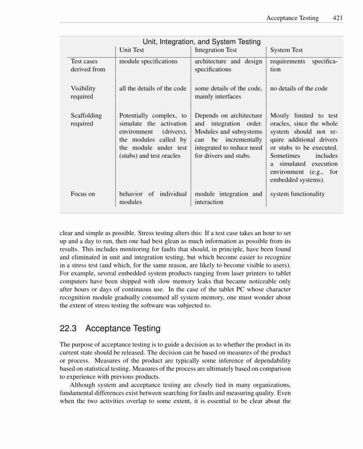
Acceptance Testing 421
Unit, Integration, and System TestingUnit Test Integration Test System Test
Test casesderived from
module specifications architecture and designspecifications
requirements specifica-tion
Visibilityrequired
all the details of the code some details of the code,mainly interfaces
no details of the code
Scaffoldingrequired
Potentially complex, tosimulate the activationenvironment (drivers),the modules called bythe module under test(stubs) and test oracles
Depends on architectureand integration order.Modules and subsystemscan be incrementallyintegrated to reduce needfor drivers and stubs.
Mostly limited to testoracles, since the wholesystem should not re-quire additional driversor stubs to be executed.Sometimes includesa simulated executionenvironment (e.g., forembedded systems).
Focus on behavior of individualmodules
module integration andinteraction
system functionality
clear and simple as possible. Stress testing alters this: If a test case takes an hour to setup and a day to run, then one had best glean as much information as possible from itsresults. This includes monitoring for faults that should, in principle, have been foundand eliminated in unit and integration testing, but which become easier to recognizein a stress test (and which, for the same reason, are likely to become visible to users).For example, several embedded system products ranging from laser printers to tabletcomputers have been shipped with slow memory leaks that became noticeable onlyafter hours or days of continuous use. In the case of the tablet PC whose characterrecognition module gradually consumed all system memory, one must wonder aboutthe extent of stress testing the software was subjected to.
22.3 Acceptance Testing
The purpose of acceptance testing is to guide a decision as to whether the product in itscurrent state should be released. The decision can be based on measures of the productor process. Measures of the product are typically some inference of dependabilitybased on statistical testing. Measures of the process are ultimately based on comparisonto experience with previous products.
Although system and acceptance testing are closely tied in many organizations,fundamental differences exist between searching for faults and measuring quality. Evenwhen the two activities overlap to some extent, it is essential to be clear about the

422 System, Acceptance, and Regression Testing
distinction, in order to avoid drawing unjustified conclusions.Quantitative goals for dependability, including reliability, availability, and mean
time between failures, were introduced in Chapter 4. These are essentially statisti-cal measures and depend on a statistically valid approach to drawing a representativesample of test executions from a population of program behaviors. Systematic testing,which includes all of the testing techniques presented heretofore in this book, doesnot draw statistically representative samples. Their purpose is not to fail at a “typical”rate, but to exhibit as many failures as possible. They are thus unsuitable for statisticaltesting.
The first requirement for valid statistical testing is a precise definition of what is be-ing measured and for what population. If system operation involves transactions, eachof which consists of several operations, a failure rate of one operation in a thousand isquite different from a failure rate of one transaction in a thousand. In addition, the fail-ure rate may vary depending on the mix of transaction types, or the failure rate may behigher when one million transactions occur in an hour than when the same transactionsare spread across a day. Statistical modeling therefore necessarily involves constructionof a model of usage, and the results are relative to that model.
Suppose, for example, that a typical session using the Chipmunk Web sales facilityconsists of 50 interactions, the last of which is a single operation in which the creditcard is charged and the order recorded. Suppose the Chipmunk software always op-erates flawlessly up to the point that a credit card is to be charged, but on half theattempts it charges the wrong amount. What is the reliability of the system? If wecount the fraction of individual interactions that are correctly carried out, we concludethat only one operation in 100 fails, so the system is 99% reliable. If we instead countentire sessions, then it is only 50% reliable, since half the sessions result in an impropercredit card charge.
Statistical models of usage, or operational profiles, may be available from measure-operational profile
ment of actual use of prior, similar systems. For example, use of a current telephonehandset may be a reasonably good model of how a new handset will be used. Goodmodels may also be obtained in embedded systems whose environment is primarilymade up of predictable devices rather than unpredictable humans. In other cases onecannot justify high confidence in a model, but one can limit the uncertainty to a smallnumber of parameters. One can perform sensitivity testing to determine which pa-sensitivity testing
rameters are critical. Sensitivity testing consists of repeating statistical tests while sys-tematically varying parameters to note the effect of each parameter on the output. Aparticular parameter may have little effect on outcomes over the entire range of plausi-ble values, or there may be an effect that varies smoothly over the range. If the effectof a given parameter is either large or varies discontinuously (e.g., performance fallsprecipitously when system load crosses some threshold), then one may need to makedistinct predictions for different value ranges.
A second problem faced by statistical testing, particularly for reliability, is that itmay take a very great deal of testing to obtain evidence of a sufficient level of relia-bility. Consider that a system that executes once per second, with a failure rate of oneexecution in a million, or 99.9999% reliability, fails about 31 times each year; this mayrequire a great testing effort and still not be adequate if each failure could result indeath or a lawsuit. For critical systems, one may insist on software failure rates that are

Usability 423
an insignificant fraction of total failures. For many other systems, statistical measuresof reliability may simply not be worth the trouble.
A less formal, but frequently used approach to acceptance testing is testing withusers. An early version of the product is delivered to a sample of users who providefeedback on failures and usability. Such tests are often called alpha and beta tests. alpha and beta
testThe two terms distinguish between testing phases. Often the early or alpha phasesare performed within the developing organization, while the later or beta phases areperformed at users’ sites.
In alpha and beta testing, the user sample determines the operational profile. Agood sample of users should include representatives of each distinct category of users,grouped by operational profile and significance. Suppose, for example, Chipmunkplans to provide Web-based sales facilities to dealers, industrial customers, and indi-viduals. A good sample should include both users from each of those three categoriesand a range of usage in each category. In the industrial user category, large customerswho frequently issue complex orders as well as small companies who typically order asmall number of units should be represented, as the difference in their usage may leadto different failure rates. We may weigh differently the frequency of failure reportsfrom dealers and from direct customers, to reflect either the expected mix of usage inthe full population or the difference in consequence of failure.
22.4 Usability
A usable product is quickly learned, allows users to work efficiently, and is pleasantto use. Usability involves objective criteria such as the time and number of operationsrequired to perform tasks and the frequency of user error, in addition to the overall,subjective satisfaction of users.
For test and analysis, it is useful to distinguish attributes that are uniquely associ-ated with usability from other aspects of software quality (dependability, performance,security, etc.). Other software qualities may be necessary for usability; for example, aprogram that often fails to satisfy its functional requirements or that presents securityholes is likely to suffer poor usability as a consequence. Distinguishing primary us-ability properties from other software qualities allows responsibility for each class ofproperties to be allocated to the most appropriate personnel, at the most cost-effectivepoints in the project schedule.
Even if usability is largely based on user perception and thus is validated based onuser feedback, it can be verified early in the design and through the whole software lifecycle. The process of verifying and validating usability includes the following mainsteps:
Inspecting specifications with usability checklists. Inspection provides early feed-back on usability.
Testing early prototypes with end users to explore their mental model (exploratorytest), evaluate alternatives (comparison test), and validate software usability. Aprototype for early assessment of usability may not include any functioning soft-

424 System, Acceptance, and Regression Testing
ware; a cardboard prototype may be as simple as a sequence of static imagespresented to users by the usability tester.
Testing incremental releases with both usability experts and end users to monitorprogress and anticipate usability problems.
System and acceptance testing that includes expert-based inspection and testing, user-based testing, comparison testing against competitors, and analysis and checksoften done automatically, such as a check of link connectivity and verification ofbrowser compatibility.
User-based testing (i.e., testing with representatives of the actual end-user popula-tion) is particularly important for validating software usability. It can be applied at dif-ferent stages, from early prototyping through incremental releases of the final system,and can be used with different goals: exploring the mental model of the user, evalu-ating design alternatives, and validating against established usability requirements andstandards.
The purpose of exploratory testing is to investigate the mental model of end users.It consists of asking users about their approach to interactions with the system. Forexploratory testing
example, during an exploratory test for the Chipmunk Web presence, we may provideusers with a generic interface for choosing the model they would like to buy, in or-der to understand how users will interact with the system. A generic interface couldpresent information about all laptop computer characteristics uniformly to see whichare examined first by the sample users, and thereby to determine the set of characteris-tics that should belong to the summary in the menu list of laptops. Exploratory test isusually performed early in design, especially when designing a system for a new targetpopulation.
The purpose of comparison testing is evaluating options. It consists of observ-ing user reactions to alternative interaction patterns. During comparison test we can,for example, provide users with different facilities to assemble the desired Chipmunklaptop configuration, and to identify patterns that facilitate users’ interactions. Com-parison test is usually applied when the general interaction patterns are clear and needto be refined. It can substitute for exploratory testing if initial knowledge about targetusers is sufficient to construct a range of alternatives, or otherwise follows exploratorytesting.
The purpose of validation testing is assessing overall usability. It includes identi-fying difficulties and obstacles that users encounter while interacting with the system,as well as measuring characteristics such as error rate and time to perform a task.
A well-executed design and organization of usability testing can produce resultsthat are objective and accurately predict usability in the target user population. The us-ability test design includes selecting suitable representatives of the target users and or-ganizing sessions that guide the test toward interpretable results. A common approachis divided into preparation, execution, and analysis phases. During the preparationphase, test designers define the objectives of the session, identify the items to be tested,select a representative population of end users, and plan the required actions. Duringexecution, users are monitored as they execute the planned actions in a controlled envi-

Usability 425
ronment. During analysis, results are evaluated, and changes to the software interfacesor new testing sessions are planned, if required.
Each phase must be carefully executed to ensure success of the testing session.User time is a valuable and limited resource. Well-focused test objectives should notbe too narrow, to avoid useless waste of resources, nor too wide, to avoid scatteringresources without obtaining useful data. Focusing on specific interactions is usuallymore effective than attempting to assess the usability of a whole program at once.For example, the Chipmunk usability test team independently assesses interactions forcatalog browsing, order definition and purchase, and repair service.
The larger the population sample, the more precise the results, but the cost of verylarge samples is prohibitive; selecting a small but representative sample is thereforecritical. A good practice is to identify homogeneous classes of users and select a setof representatives from each class. Classes of users depend on the kind of applicationto be tested and may be categorized by role, social characteristics, age, and so on. Atypical compromise between cost and accuracy for a well-designed test session is fiveusers from a unique class of homogeneous users, four users from each of two classes, orthree users for each of three or more classes. Questionnaires should be prepared for theselected users to verify their membership in their respective classes. Some approachesalso assign a weight to each class, according to their importance to the business. Forexample, Chipmunk can identify three main classes of users: individual, business, andeducation customers. Each of the main classes is further divided. Individual customersare distinguished by education level; business customers by role; and academic cus-tomers by size of the institution. Altogether, six putatively homogeneous classes areobtained: Individual customers with and without at least a bachelor degree, managersand staff of commercial customers, and customers at small and large education institu-tions.
Users are asked to execute a planned set of actions that are identified as typicaluses of the tested feature. For example, the Chipmunk usability assessment team mayask users to configure a product, modify the configuration to take advantage of somespecial offers, and place an order with overnight delivery.
Users should perform tasks independently, without help or influence from the test-ing staff. User actions are recorded, and comments and impressions are collected witha post-activity questionnaire. Activity monitoring can be very simple, such as record-ing sequences of mouse clicks to perform each action. More sophisticated monitoringcan include recording mouse or eye movements. Timing should also be recorded andmay sometimes be used for driving the sessions (e.g., fixing a maximum time for thesession or for each set of actions).
An important aspect of usability is accessibility to all users, including those withdisabilities. Accessibility testing is legally required in some application domains. Forexample, some governments impose specific accessibility rules for Web applications ofpublic institutions. The set of Web Content Accessibility Guidelines (WCAG) definedby the World Wide Web Consortium are becoming an important standard reference.The WCAG guidelines are summarized in the sidebar on page 426.

426 System, Acceptance, and Regression Testing
Web Content Accessibility Guidelines (WCAG)a
1. Provide equivalent alternatives to auditory and visual content that convey essen-tially the same function or purpose.
2. Ensure that text and graphics are understandable when viewed without color.
3. Mark up documents with the proper structural elements, controlling presentationwith style sheets rather than presentation elements and attributes.
4. Use markup that facilitates pronunciation or interpretation of abbreviated or for-eign text.
5. Ensure that tables have necessary markup to be transformed by accessiblebrowsers and other user agents.
6. Ensure that pages are accessible even when newer technologies are not supportedor are turned off.
7. Ensure that moving, blinking, scrolling, or auto-updating objects or pages maybe paused or stopped.
8. Ensure that the user interface, including embedded user interface elements, fol-lows principles of accessible design: device-independent access to functionality,keyboard operability, self-voicing, and so on.
9. Use features that enable activation of page elements via a variety of input de-vices.
10. Use interim accessibility so that assisting technologies and older browsers willoperate correctly.
11. Where technologies outside of W3C specifications is used (e.g, Flash), providealternative versions to ensure accessibility to standard user agents and assistivetechnologies (e.g., screen readers).
12. Provide context and orientation information to help users understand complexpages or elements.
13. Provide clear and consistent navigation mechanisms to increase the likelihoodthat a person will find what they are looking for at a site.
14. Ensure that documents are clear and simple, so they may be more easily under-stood.
aExcerpted and adapted from Web Content Accessibility Guidelines 1.0, W3C Recommendation 5-May1999; used by permission. The current version is distributed by W3C at http://www.w3.org/TR/WAI-WEBCONTENT.

Regression Testing 427
22.5 Regression Testing
When building a new version of a system (e.g., by removing faults, changing or addingfunctionality, porting the system to a new platform, or extending interoperability), wemay also change existing functionality in unintended ways. Sometimes even smallchanges can produce unforeseen effects that lead to new failures. For example, a guardadded to an array to fix an overflow problem may cause a failure when the array is usedin other contexts, or porting the software to a new platform may expose a latent faultin creating and modifying temporary files.
When a new version of software no longer correctly provides functionality thatshould be preserved, we say that the new version regresses with respect to formerversions. The nonregression of new versions (i.e., preservation of functionality), is abasic quality requirement. Disciplined design and development techniques, includingprecise specification and modularity that encapsulates independent design decisions,improves the likelihood of achieving nonregression. Testing activities that focus onregression problems are called (non) regression testing. Usually “non” is omitted andwe commonly say regression testing.
A simple approach to regression testing consists of reexecuting all test cases de-signed for previous versions. Even this simple retest all approach may present nontriv- retest all
ial problems and costs. Former test cases may not be reexecutable on the new versionwithout modification, and rerunning all test cases may be too expensive and unneces-sary. A good quality test suite must be maintained across system versions.
Changes in the new software version may impact the format of inputs and outputs,and test cases may not be executable without corresponding changes. Even simple test case
maintenancemodifications of the data structures, such as the addition of a field or small change ofdata types, may invalidate former test cases, or outputs comparable with the new ones.Moreover, some test cases may be obsolete, since they test features of the software thathave been modified, substituted, or removed from the new version.
Scaffolding that interprets test case specifications, rather than fully concrete testdata, can reduce the impact of input and output format changes on regression testing,as discussed in Chapter 17. Test case specifications and oracles that capture essentialcorrectness properties, abstracting from arbitrary details of behavior, likewise reducethe likelihood that a large portion of a regression test suite will be invalidated by aminor change.
High-quality test suites can be maintained across versions by identifying and re-moving obsolete test cases, and by revealing and suitably marking redundant test cases.Redundant cases differ from obsolete, being executable but not important with respectto the considered testing criteria. For example, test cases that cover the same path aremutually redundant with respect to structural criteria, while test cases that match thesame partition are mutually redundant with respect to functional criteria. Redundanttest cases may be introduced in the test suites due to concurrent work of different testdesigners or to changes in the code. Redundant test cases do not reduce the overalleffectiveness of tests, but impact on the cost-benefits trade-off: They are unlikely toreveal faults, but they augment the costs of test execution and maintenance. Obsoletetest cases are removed because they are no longer useful, while redundant test casesare kept because they may become helpful in successive versions of the software.

428 System, Acceptance, and Regression Testing
Good test documentation is particularly important. As we will see in Chapter 24,test specifications define the features to be tested, the corresponding test cases, theinputs and expected outputs, as well as the execution conditions for all cases, whilereporting documents indicate the results of the test executions, the open faults, andtheir relation to the test cases. This information is essential for tracking faults and foridentifying test cases to be reexecuted after fault removal.
22.6 Regression Test Selection Techniques
Even when we can identify and eliminate obsolete test cases, the number of tests tobe reexecuted may be large, especially for legacy software. Executing all test casesfor large software products may require many hours or days of execution and maydepend on scarce resources such as an expensive hardware test harness. For example,some mass market software systems must be tested for compatibility with hundredsof different hardware configurations and thousands of drivers. Many test cases mayhave been designed to exercise parts of the software that cannot be affected by thechanges in the version under test. Test cases designed to check the behavior of the filemanagement system of an operating system is unlikely to provide useful informationwhen reexecuted after changes of the window manager. The cost of reexecuting atest suite can be reduced by selecting a subset of test cases to be reexecuted, omittingirrelevant test cases or prioritizing execution of subsets of the test suite by their relationto changes.
Test case prioritization orders frequency of test case execution, executing all ofthem eventually but reducing the frequency of those deemed least likely to reveal faultsby some criterion. Alternate execution is a variant on prioritization for environmentswith frequent releases and small incremental changes; it selects a subset of regressiontest cases for each software version. Prioritization can be based on the specificationand code-based regression test selection techniques described later in this chapter. Inaddition, test histories and fault-proneness models can be incorporated in prioritizationschemes. For example, a test case that has previously revealed a fault in a module thathas recently undergone change would receive a very high priority, while a test casethat has never failed (yet) would receive a lower priority, particularly if it primarilyconcerns a feature that was not the focus of recent changes.
Regression test selection techniques are based on either code or specifications.Code-based selection techniques select a test case for execution if it exercises a portionof the code that has been modified. Specification-based criteria select a test case forexecution if it is relevant to a portion of the specification that has been changed. Code-based regression test techniques can be supported by relatively simple tools. Theywork even when specifications are not properly maintained. However, like code-basedtest techniques in general, they do not scale well from unit testing to integration andsystem testing. In contrast, specification-based criteria scale well and are easier to ap-ply to changes that cut across several modules. However, they are more challenging toautomate and require carefully structured and well-maintained specifications.
Among code-based test selection techniques, control-based techniques rely on arecord of program elements executed by each test case, which may be gathered from

Regression Test Selection Techniques 429
an instrumented version of the program. The structure of the new and old versionsof the program are compared, and test cases that exercise added, modified, or deletedelements are selected for reexecution. Different criteria are obtained depending on theprogram model on which the version comparison is based (e.g., control flow or dataflow graph models).
Control flow graph (CFG) regression techniques are based on the differences be-tween the CFGs of the new and old versions of the software. Let us consider, for control flow
graph (CFG)regression test
example, the C function cgi decode from Chapter 12. Figure 22.1 shows the originalfunction as presented in Chapter 12, while Figure 22.2 shows a revison of the program.We refer to these two versions as 1.0 and 2.0, respectively. Version 2.0 adds code tofix a fault in interpreting hexadecimal sequences ’%xy’. The fault was revealed bytesting version 1.0 with input terminated by an erroneous subsequence ’%x’, causingversion 1.0 to read past the end of the input buffer and possibly overflow the outputbuffer. Version 2.0 contains a new branch to map the unterminated sequence to a ques-tion mark.
Let us consider all structural test cases derived for cgi decode in Chapter 12, andassume we have recorded the paths exercised by the different test cases as shown inFigure 22.3. Recording paths executed by test cases can be done automatically withmodest space and time overhead, since what must be captured is only the set of programelements exercised rather than the full history.
CFG regression testing techniques compare the annotated control flow graphs of thetwo program versions to identify a subset of test cases that traverse modified parts ofthe graphs. The graph nodes are annotated with corresponding program statements, sothat comparison of the annotated CFGs detects not only new or missing nodes and arcs,but also nodes whose changed annotations correspond to small, but possibly relevant,changes in statements.
The CFG for version 2.0 of cgi decode is given in Figure 22.4. Differences betweenversion 2.0 and 1.0 are indicated in gray. In the example, we have new nodes, arcs andpaths. In general, some nodes or arcs may be missing (e.g., when part of the program isremoved in the new version), and some other nodes may differ only in the annotations(e.g., when we modify a condition in the new version).
CFG criteria select all test cases that exercise paths through changed portions ofthe CFG, including CFG structure changes and node annotations. In the example, wewould select all test cases that pass through node D and proceed toward node G andall test cases that reach node L, that is, all test cases except TC1. In this example, thecriterion is not very effective in reducing the size of the test suite because modifiedstatements affect almost all paths.
If we consider only the corrective modification (nodes X and Y ), the criterion ismore effective. The modification affects only the paths that traverse the edge betweenD and G, so the CFG regression testing criterion would select only test cases traversingthose nodes (i.e., TC2, TC3, TC4, TC5, TC8 and TC9). In this case the size of the testsuite to be reexecuted includes two-thirds of the test cases of the original test suite.
In general, the CFG regression testing criterion is effective only when the changesaffect a relatively small subset of the paths of the original program, as in the latter case.It becomes almost useless when the changes affect most paths, as in version 2.0.
Data flow (DF) regression testing techniques select test cases for new and modi-

430 System, Acceptance, and Regression Testing
1 #include "hex values.h"
2 /** Translate a string from the CGI encoding to plain ascii text.3 * ’+’ becomes space, %xx becomes byte with hex value xx,4 * other alphanumeric characters map to themselves.5 * Returns 0 for success, positive for erroneous input6 * 1 = bad hexadecimal digit7 */8 int cgi decode(char *encoded, char *decoded) {9 char *eptr = encoded;
10 char *dptr = decoded;11 int ok=0;12 while (*eptr) {13 char c;14 c = *eptr;15 if (c == ’+’) { /* Case 1: ’+’ maps to blank */16 *dptr = ’ ’;17 } else if (c == ’%’) { /* Case 2: ’%xx’ is hex for character xx */18 int digit high = Hex Values[*(++eptr)]; /* note illegal => -1 */19 int digit low = Hex Values[*(++eptr)];20 if ( digit high == -1 || digit low == -1 ) {21 /* *dptr=’?’; */22 ok=1; /* Bad return code */23 } else {24 *dptr = 16* digit high + digit low;25 }26 } else { /* Case 3: Other characters map to themselves */27 *dptr = *eptr;28 }29 ++dptr;30 ++eptr;31 }32 *dptr = ’\0’; /* Null terminator for string */33 return ok;34 }
Figure 22.1: C function cgi decode version 1.0. The C function cgi decode translates acgi-encoded string to a plain ASCII string, reversing the encoding applied by the com-mon gateway interface of most Web servers. Repeated from Figure 12.1 in Chapter 12.
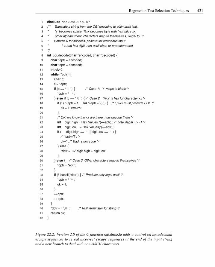
Regression Test Selection Techniques 431
1 #include "hex values.h"
2 /** Translate a string from the CGI encoding to plain ascii text.3 * ’+’ becomes space, %xx becomes byte with hex value xx,4 * other alphanumeric characters map to themselves, illegal to ’?’.5 * Returns 0 for success, positive for erroneous input6 * 1 = bad hex digit, non-ascii char, or premature end.7 */8 int cgi decode(char *encoded, char *decoded) {9 char *eptr = encoded;
10 char *dptr = decoded;11 int ok=0;12 while (*eptr) {13 char c;14 c = *eptr;15 if (c == ’+’) { /* Case 1: ’+’ maps to blank */16 *dptr = ’ ’;17 } else if (c == ’%’) { /* Case 2: ’%xx’ is hex for character xx */18 if (! ( *(eptr + 1) && *(eptr + 2) )) { /* \%xx must precede EOL */19 ok = 1; return;20 }21 /* OK, we know the xx are there, now decode them */22 int digit high = Hex Values[*(++eptr)]; /* note illegal => -1 */23 int digit low = Hex Values[*(++eptr)];24 if ( digit high == -1 || digit low == -1 ) {25 /* *dptr=’?’; */26 ok=1; /* Bad return code */27 } else {28 *dptr = 16* digit high + digit low;29 }30 } else { /* Case 3: Other characters map to themselves */31 *dptr = *eptr;32 }33 if (! isascii(*dptr)) { /* Produce only legal ascii */34 *dptr = ’?’;35 ok = 1;36 }37 ++dptr;38 ++eptr;39 }40 *dptr = ’\0’; /* Null terminator for string */41 return ok;42 }
Figure 22.2: Version 2.0 of the C function cgi decode adds a control on hexadecimalescape sequences to reveal incorrect escape sequences at the end of the input stringand a new branch to deal with non-ASCII characters.

432 System, Acceptance, and Regression Testing
Id Test case PathTC1 “ ” A B MTC2 “test+case%1Dadequacy” A B C D F L ... B MTC3 “adequate+test%0Dexecution%7U” A B C D F L ... B MTC4 “%3D” A B C D G H L B MTC5 “%A” A B C D G I L B MTC6 “a+b” A B C D F L B C E L B C D F L B MTC7 “test” A B C D F L B C D F L B C D F L B C D F L B MTC8 “+%0D+%4J” A B C E L B C D G I L ... B MTC9 “first+test%9Ktest%K9” A B C D F L ... B M
Figure 22.3: Paths covered by the structural test cases derived for version 1.0 of func-tion cgi decode. Paths are given referring to the nodes of the control flow graph ofFigure 22.4.
fied pairs of definitions with uses (DU pairs, cf. Sections 6.1, page 77 and 13.2, page236). DF regression selection techniques reexecute test cases that, when executed ondata flow (DF)
regression test the original program, exercise DU pairs that were deleted or modified in the revisedprogram. Test cases that executed a conditional statement whose predicate was alteredare also selected, since the changed predicate could alter some old definition-use asso-ciations. Figure 22.5 shows the new definitions and uses introduced by modificationsto cgi decode.1 These new definitions and uses introduce new DU pairs and removeothers.
In contrast to code-based techniques, specification-based test selection techniquesdo not require recording the control flow paths executed by tests. Regression test casescan be identified from correspondence between test cases and specification items. Forexample, when using category partition, test cases correspond to sets of choices, whilein finite state machine model-based approaches, test cases cover states and transitions.Where test case specifications and test data are generated automatically from a spec-ification or model, generation can simply be repeated each time the specification ormodel changes.
Code-based regression test selection criteria can be adapted for model-based re-gression test selection. Consider, for example, the control flow graph derived from theprocess shipping order specification in Chapter 14. We add the following item to thatspecification:
Restricted countries: A set of restricted destination countries is maintained, based oncurrent trade restrictions. If the shipping address contains a restricted destina-tion country, only credit card payments are accepted for that order, and shipping
1When dealing with arrays, we follow the criteria discussed in Chapter 13: A change of an array valueis a definition of the array and a use of the index. A use of an array value is a use of both the array and theindex.

Regression Test Selection Techniques 433
True
*dptr = '\0';return ok;}
False
True
int digit_high = Hex_Values[*(++eptr)];int digit_low = Hex_Values[*(++eptr)];if (digit_high == -1 || digit_low == -1) {
True
ok = 1;}
Trueelse {*dptr = 16 * digit_high + digit_low;}
False
False
False
else*dptr = *eptr;}
int cgi_decode(char *encoded, char *decoded)
F G
H I
M
{ char *eptr = encoded;char *dptr = decoded;int ok = 0;
A
while (*eptr) { B
char c;c = *eptr;if (c == '+') {
C
*dptr = ' ';}
E elseif (c == '%') {D
ok = 1; return; }
if (! ( *(eptr + 1) && *(eptr + 2) )) { X
YTrue False
if (! isascii(*dptr)) { W
*dptr = '?'; ok = 1; }
Z
++dptr;++eptr;}
L
True
False
Figure 22.4: The control flow graph of function cgi decode version 2.0. Gray back-ground indicates the changes from the former version.

434 System, Acceptance, and Regression Testing
Variable Definitions Uses*eptr Xeptr Xdptr Z Wdptr Z Wok Y Z
Figure 22.5: Definitions and uses introduced by changes in cgi decode. Labels refer tothe nodes in the control flow graph of Figure 22.4.
proceeds only after approval by a designated company officer responsible forchecking that the goods ordered may be legally exported to that country.
The new requirement can be added to the flow graph model of the specification asillustrated in Figure 22.6.
We can identify regression test cases with the CFG criterion that selects all casesthat correspond to international shipping addresses (i.e., test cases TC-1 and TC-5 fromthe following table). The table corresponds to the functional test cases derived using tothe method described in Chapter 14 on page 259.
Case Too Ship Ship Cust Pay Same CCsmall where method type method addr valid
TC-1 No Int Air Bus CC No YesTC-2 No Dom Land – – – –TC-3 Yes – – – – – –TC-4 No Dom Air – – – –TC-5 No Int Land – – – –TC-6 No – – Edu Inv – –TC-7 No – – – CC Yes –TC-8 No – – – CC – No (abort)TC-9 No – – – CC – No (no abort)
Models derived for testing can be used not only for selecting regression test cases,but also for generating test cases for the new code. In the preceding example, we canuse the model not only to identify the test cases that should be reused, but also to gen-erate new test cases for the new functionality, following the combinatorial approachesdescribed in Chapter 11.
22.7 Test Case Prioritization and Selective Execution
Regression testing criteria may select a large portion of a test suite. When a regressiontest suite is too large, we must further reduce the set of test cases to be executed.
Random sampling is a simple way to reduce the size of the regression test suite.Better approaches prioritize test cases to reflect their predicted usefulness. In a con-

Test Case Prioritization and Selective Execution 435
preferred shipping method = land freight, OR expedited land freight OR overnight air
Process shipping order
CostOfGoods < MinOrder
shipping addressno
yes
domestic
preferred shipping method = air freight OR expedited air freight
international
calculate domestic shipping charge
calculate international shipping charge
total charge = goods + shipping
individual customer no
yes
obtain credit card data: number, name on card, expiration date
method of payementcredit card
invoice
billing address = shipping address
obtain billing address
noyes
valid credit card information
no
yes
payement status = validenter order
prepare receipt
invalid order
no
no
abort order?
no
yes
Shipping address in {restricted countries}
order in {allowed goods}noyes
noyes
Figure 22.6: A flow graph model of the specification of the shipping order functionalitypresented in Chapter 14, augmented with the “restricted country” requirement. Thechanges in the flow graph are indicated in black.

436 System, Acceptance, and Regression Testing
tinuous cycle of retesting as the product evolves, high-priority test cases are selectedmore often than low-priority test cases. With a good selection strategy, all test cases areexecuted sooner or later, but the varying periods result in an efficient rotation in whichthe cases most likely to reveal faults are executed most frequently.
Priorities can be assigned in many ways. A simple priority scheme assigns priorityaccording to the execution history: Recently executed test cases are given low priority,while test cases that have not been recently executed are given high priority. In theexecution history
priority schema extreme, heavily weighting execution history approximates round robin selection.Other history-based priority schemes predict fault detection effectiveness. Test
cases that have revealed faults in recent versions are given high priority. Faults arefault revealingpriority schema not evenly distributed, but tend to accumulate in particular parts of the code or around
particular functionality. Test cases that exercised faulty parts of the program in the pastoften exercise faulty portions of subsequent revisions.
Structural coverage leads to a set of priority schemes based on the elements coveredby a test case. We can give high priority to test cases that exercise elements that havestructural priority
schema not recently been exercised. Both the number of elements covered and the “age” ofeach element (time since that element was covered by a test case) can contribute to theprioritization.
Structural priority schemes produce several criteria depending on which elementswe consider: statements, conditions, decisions, functions, files, and so on. The choiceof the element of interest is usually driven by the testing level. Fine-grain elementssuch as statements and conditions are typically used in unit testing, while in integrationor system testing one can consider coarser grain elements such as methods, features,and files.
Open Research Issues
System requirements include many nonfunctional behavioral properties. While there isan active research community in reliability testing, in general, assessment of nonfunc-tional properties is not as well-studied as testing for correctness. Moreover, as trendsin software develop, new problems for test and analysis are following the emphasis onparticular nonfunctional properties. A prominent example of this over the last severalyears, and with much left to do, is test and analysis to assess and improve security.
Selective regression test selection based on analysis of source code is now well-studied. There remains need and opportunity for improvement in techniques that giveup the safety guarantee (selecting all test cases that might be affected by a softwarechange) to obtain more significant test suite reductions. Specification-based regressiontest selection is a promising avenue of research, particularly as more systems incorpo-rate components without full source code.
Increasingly ubiquitous network access is blurring the once-clear lines betweenalpha and beta testing and opening possibilities for gathering much more informationfrom execution of deployed software. We expect to see advances in approaches to gath-ering information (both from failures and from normal execution) as well as exploitingpotentially large amounts of gathered information. Privacy and confidentiality are animportant research challenge in postdeployment monitoring.

Test Case Prioritization and Selective Execution 437
Further Reading
Musa [Mus04] is a guide to reliability engineering from a pioneer in the field; ongoingresearch appears in the International Symposium on Software Reliability Engineer-ing (ISSRE) conference series. Graves et al. [GHK+98] and Rothermel and Har-rold [RH97] provide useful overviews of selective regression testing. Kim and Porter[KP02] describe history-based test prioritization. Barnum [Bar01] is a well-regardedtext on usability testing; Nielsen [Nie00] is a broader popular introduction to usabilityengineering, with a chapter on usability testing.
Exercises
22.1. Consider the Chipmunk Computer Web presence. Define at least one test casethat may serve both during final integration and early system testing, at least onethat serves only as an integration test case, and at least one that is more suitableas a system test case than as a final integration test case. Explain your choices.
22.2. When and why should testing responsibilities shift from the development team toan independent quality team? In what circumstances might using an independentquality team be impractical?
22.3. Identify some kinds of properties that cannot be efficiently verified with systemtesting, and indicate how you would verify them.
22.4. Provide two or more examples of resource limitations that may impact systemtest more than module and integration test. Explain the difference in impact.
22.5. Consider the following required property of the Chipmunk Computer Web pres-ence:
Customers should perceive that purchasing a computer using the Chip-munk Web presence is at least as convenient, fast, and intuitive aspurchasing a computer in an off-line retail store.
Would you check it as part of system or acceptance testing? Reformulate theproperty to allow test designers to check it in a different testing phase (systemtesting, if you consider the property checkable as part of acceptance testing, orvice versa).

438 System, Acceptance, and Regression Testing

Chapter 23
Automating Analysis andTest
Automation can improve the efficiency of some quality activities and is a necessity forimplementing others. While a greater degree of automation can never substitute fora rational, well-organized quality process, considerations of what can and should beautomated play an important part in devising and incrementally improving a processthat makes the best use of human resources. This chapter discusses some of the waysthat automation can be employed, as well as its costs and limitations, and the maturityof the required technology. The focus is not on choosing one particular set of “best”tools for all times and situations, but on a continuing rational process of identifyingand deploying automation to best effect as the organization, process, and availabletechnology evolve.
Required Background
• Chapter 20Some knowledge about planning and monitoring, though not strictly required,can be useful to understand the need for automated management support.
• Chapter 17Some knowledge about execution and scaffolding is useful to appreciate the im-pact of tools for scaffolding generation and test execution.
• Chapter 19Some knowledge about program analysis is useful to understand the need toautomate analysis techniques.
23.1 Overview
A rational approach to automating test and analysis proceeds incrementally, prioritiz-ing the next steps based on variations in potential impact, variations in the maturity,
439

440 Automating Analysis and Test
cost, and scope of the applicable technology, and fit and impact on the organizationand process. The potential role of automation in test and analysis activities can be con-sidered along three nonorthogonal dimensions: the value of the activity and its currentcost, the extent to which the activity requires or is made less expensive by automation,and the cost of obtaining or constructing tool support.
Some test and analysis tasks depend so heavily on automation that a decision toemploy a technique is tantamount to a decision to use tools. For example, employingstructural coverage criteria in program testing necessarily means using coverage mea-surement tools. In other cases, an activity may be carried out manually, but automationreduces cost or improves effectiveness. For example, tools for capturing and replayingexecutions reduce the costs of reexecuting test suites and enable testing strategies thatwould be otherwise impractical. Even tasks that appear to be inherently manual maybe enhanced with automation. For example, although software inspection is a manualactivity at its core, a variety of tools have been developed to organize and present infor-mation and manage communication for software inspection, improving the efficiencyof inspectors.
The difficulty and cost of automating test and analysis vary enormously, rangingfrom tools that are so simple to develop that they are justifiable even if their benefitsare modest to tools that would be enormously valuable but are simply impossible. Forexample, if we have specification models structured as finite state machines, automaticgeneration of test case specifications from the finite state model is a sufficiently simpleand well-understood technique that obtaining or building suitable tools should not be anobstacle. At the other extreme, as we have seen in Chapter 2, many important problemsregarding programs are undecidable. For example, no matter how much value we mightderive from a tool that infallibly distinguishes executable from nonexecutable programpaths, no such tool can exist. We must therefore weigh the difficulty or expense ofautomation together with potential benefits, including costs of training and integration.
Difficulty and cost are typically entangled with scope and accuracy. Sometimesa general-purpose tool (e.g., capture and replay for Windows applications) is onlymarginally more difficult to produce than a tool specialized for one project (e.g., cap-ture and replay for a specific Windows application). Investment in the general-purposetool, whether to build it or to buy it, can be amortized across projects. In other cases, itmay be much more cost-effective to create simple, project-specific tools that sidestepthe complexity of more generic tools.
However industrious and well-intentioned, humans are slow and error-prone whendealing with repetitive tasks. Conversely, simple repetitive tasks are often straightfor-ward to automate, while judgment and creative problem solving remain outside thedomain of automation. Human beings are very good at identifying the relevant exe-cution scenarios that correspond to test case specifications (for example, by specifyingthe execution space of the program under test with a finite state machine), but are veryinefficient in generating large volumes of test cases (for example, by clicking combi-nations of menus in graphic interfaces), or identifying erroneous results within a largeset of outputs produced when executing regression tests. Automating the repetitiveportions of the task not only reduces costs, but improves accuracy as well.
Automation and Planning 441
23.2 Automation and Planning
One important role of a test strategy is to prescribe tools for key elements of the qualityprocess used in the organization. Analysis and test strategies can include very detailedprocess and tool prescriptions, particularly in critical application domains where qual-ity assurance procedures are imposed by certification agencies, as in avionics software.In general, however, a single detailed process and its supporting tools will not be auniformly good fit for a diverse set of software projects. Rather, an analysis and testingstrategy can recommend different tools contingent on aspects of a project includingapplication domain, development languages, and size. Overall quality strategies oftenindicate tools for organizing test design and execution and for generating quality doc-uments, for collecting metrics, and for managing regression test suites. They less oftenindicate tools for generating test cases from requirement and design specifications, orfor dynamic analysis.
The quality plan for a particular project indicates tools inherited from the strategyas well as additional tools selected for that project. The quality manager should alsoevaluate needs and opportunities for acquiring or customizing existing tools or develop-ing ad hoc solutions. For both organization-standard and project-specific tool choices,the plan must include related costs such as training, implied activities, and potentialrisks.
The quality strategy and plan must position tools within a development process andan analysis and test methodology. Tools are worthless and even harmful if not properlycontextualized. For example, while tools for measuring code coverage are simple andinexpensive, if not preceded by careful consideration of the role of coverage metricsin the test process, they are at best an annoyance, producing data that are not put toproductive use, and at worst a distorting influence that steers the process in unplannedways.
23.3 Process Management
Managing a quality process involves planning a set of activities with appropriate costand quality trade-offs, monitoring progress to identify risks as early as possible and toavoid delays, and adjusting the plan as needed. These tasks require human creativityand insight for which no tool can substitute. Nonetheless, tools can support processmanagement, improving decision making by organizing and monitoring activities andresults, facilitating group interaction, managing quality documents, and tracking costs.
Classic planning tools facilitate task scheduling, resource allocation, and cost es-timation by arranging tasks according to resource and time constraints. They can bespecialized to analysis and test management with features for automatically derivingrelations among tasks, launching tasks, and monitoring completion of activities. Forexample, quality planning tools can schedule test generation and execution activitiesconsistent with dependence among quality activities and between quality and develop-ment activities. They can recognize delivery of a given artifact, automatically scheduleexecution of a corresponding test suite, notify the test designer of test results, recordthe actual execution time of the activity, and signal schedule deviations to the qual-

442 Automating Analysis and Test
ity manager. Quality planning tools are most useful when integrated in the analysisand test environment to react automatically to events with activation of other tools andprocedures.
Analysis and testing involve complex relations among a large number of artifacts.A failure of a particular test case may be specific to a particular version of a modulein some configurations of a system and to portions of a design specification that isin turn tied back to product requirements. An inspection may detect a fault indicatedby a particular checklist item, which is applied by inspectors when they recognizea particular software design pattern, and that fault is also related to elements of theprogram, design, and version and configuration information. In most developmentprojects, managing those relations, deriving useful information from them, and takingappropriate action are major tasks themselves.
Fortunately, managing the Web of relations among artifacts can be automated andmanaged by version control tools. Version and configuration control tools relate ver-sions of software artifacts and are often used to trigger consistency checks and otheractivities. They can support analysis and testing activities in much the same manner asthey control assembly and compilation of related modules, for example, triggering exe-cution of the appropriate test suites for each software modification, associating versionstatus with test reports, and tracking completion of follow-up activities for detectedfailures. In other words, artifacts and tasks related to quality are simply part of theproduct and development process, with the same requirements and opportunities forautomated support. Also like other aspects of a development environment, integratedquality tracking improves efficiency in a well-structured process, but does not by itselfbring order out of chaos.
Process management includes monitoring progress in terms of both schedule (com-paring actual effort and completion times to a plan) and level of quality. Quality of thefinal product cannot be directly measured before its completion, but useful indicationscan be derived, for example, using the orthogonal defect classification discussed inChapter 20. For both schedule and quality, the essential function of tracking is to rec-ognize deviations from expectation, so that an alert manager can direct attention tounderstanding and dealing with problems before they are insurmountable.
Essential tasks that require human ingenuity include selecting or designing proxymeasures that can be computed early, and interpreting those measures in a way thatavoids misleading conclusions or distorted incentives. For example, counting lines ofcode is sometimes useful as a simple proxy for productivity, but must be carefully inter-preted to avoid creating an incentive for verbosity or a disincentive for effective reuseof components. Similarly, the number of faults detected is a useful proxy measure if thegoal is simply to detect deviations from the norm, but one should be as concerned aboutthe causes of abnormally low numbers as high. Collection, summary, and presentationof data can be automated; design and interpretation cannot.
Effective management also involves coordinating people, who may work in dif-ferent groups or even different companies, possibly distributed across time zones andcontinents. Several studies have indicated that a large proportion of a software engi-neer’s time is devoted to communication. It is therefore important both to facilitateeffective communication and to limit disruptions and distractions of unmanaged com-munication.

Static Metrics 443
Where simple general-purpose tools like e-mail, chats, and forums are employed,a key factor in their efficiency is appropriately matching synchronous communicationor asynchronous communication to tasks. When excessive interruptions slow progress,replacing synchronous communication by asynchronous or scheduled communicationmay be indicated. Conversely, asynchronous communication may be replaced or aug-mented with synchronous communication (e.g., messaging or chat) to improve the effi-ciency of discussions that have been splintered into many small exchanges punctuatedby waits for reply.
Communication is most effective when all parties have immediate access to rele-vant information. In this regard, task-specific tools can improve on general-purposecommunication support. For example, tools for distributed software inspections extendthe familiar interfaces for chat (for synchronous inspection) or forum (for asynchronousinspection), adding managed presentation of the artifact to be inspected and appropriateportions of checklists and automated analysis results.
23.4 Static Metrics
Static metrics measure software properties, often to estimate other properties. Amongthe most basic properties of software is size, which is strongly correlated to scheduleand cost, including the cost of testing. Even something as straightforward as countinglines of code turns out to have several possible variations, depending on whether andhow one filters out variations in white space, comments, and programming style. Com-mon metrics of code size include:
Size Size of the source file, measured in bytesLines All-inclusive count of lines in source code fileLOC Lines of code, excluding comment and blank lineseLOC Effective lines of code, excluding comments, blank lines, and stand-alone
braces or parenthesislLOC Logical lines of code, that is, statements as identified by logical separa-
tors such as semicolons
Every programmer knows that there are variations in complexity between differentpieces of code and that this complexity may be as important as sheer size. A numberof attempts have been made to quantify aspects of complexity and readability:
CDENS Comment density (i.e., comment lines/eLOC)Blocks Number of basic blocks (i.e., sequences of statements with one entry
point, one exit point, and no internal branches)AveBlockL Average number of lines per basic blockNEST Control structure nesting level (minimum, maximum, and average)Loops Number of loopsLCSAJ Number of linear code sequences; see Chapter 5BRANCH Number of branches in the control flow graph
Size and complexity may also be estimated on a coarser scale, considering only inter-faces between units:

444 Automating Analysis and Test
Cyclomatic ComplexityCyclomatic complexity is measured as e−n+2, where e is the number of edges of
the control flow graph and n is the number of nodes in the graph.Cyclomatic complexity does not depend on the size of the code but on branching
in the control structure. For example, graphs CFG1 and CFG2, as follow, have thesame cyclomatic complexity, despite their different sizes, while the cyclomatic com-plexity of CFG3 is higher than that of CFG2 despite having the same number of nodes.
V(g) = 1 - 2 + 2 = 1
V(g) = 5 - 6 + 2 = 1
CFG1 CFG2 CFG3
V(g) = 8 - 6 + 2 = 4
Low to moderate cyclomatic complexity (below 20) is interpreted as indicating asimple program; high cyclomatic complexity (above 20) indicates complex programs;very high cyclomatic complexity (above 50) characterizes programs that may be verydifficult or impossible to thoroughly test.
Cyclomatic complexity is certainly a sign of complex control flow structure, butit does not capture other aspects of logical complexity that can lead to difficulty intesting. There is little evidence that cyclomatic complexity is a more reliable predictorof testing effort or quality than lines of code.
Functions Number of defined functions (or methods, procedures, etc.)FPar Number of formal parameters of functionsFRet Number of return points of functionsIComplex Interface complexity (i.e., FPar +FRet)
All these metrics are proxies for size and complexity. Despite several attempts begin-ning in the 1970s, no proposed metric has succeeded in capturing intrinsic complexityin a manner that robustly correlates with effort or quality. Lines of code, despite its ob-vious shortcomings, is not much worse than other measures of size. Among attemptsto measure complexity, only cyclomatic complexity (V (g)) is still commonly collectedby many tools (see sidebar). Cyclomatic complexity is defined as the number of inde-pendent paths through the control flow graph.
Additional metrics have been introduced to capture complexity in structures uniqueto object-oriented programming:

Test Case Generation and Execution 445
WMC Weighted methods per class, the sum of the complexities of methods inall classes, divided by the number of classes. This metric is parametricwith respect to a measure of complexity in methods
DIT Depth of the inheritance tree of a classNOC Number of children (subclasses) of a classRFC Response for a class, the number of methods that may be executed in re-
sponse to a method call to an object of the class. The size of the transitiveclosure of the calling relation rooted at a class
CBO Coupling between object classes, the number of classes with which theclass is coupled through any relation (e.g., containment, method calls,subclassing)
LCOM Lack of cohesion in methods, the number of methods with pairwise dis-joint sets of instance variables referenced within their respective methodbodies
All metrics discussed so far focus on code structure and can be measured onlywhen the code is available, often late in the development process. A subset of theobject-oriented metrics can be derived from detailed design, which still may be too latefor many purposes.
Many standards define metrics. The well-known ISO/IEC 9126 standard (sidebaron page 446) suggests a hierarchy of properties to measure the quality of software.The six main high-level quality dimensions identified by the ISO/IEC 9126 standarddescribe quality properties as perceived by users.
23.5 Test Case Generation and Execution
Test case generation and execution can be a large fraction of overall cost for test andanalysis, and if done poorly can become a scheduling bottleneck near product deliverydeadlines. Although designing a test suite involves human creativity in the same degreeas other kinds of design, instantiating and executing test cases is a repetitive and tedioustask that can be largely automated, reducing overall cost and accelerating the test cycle.
Technical aspects of test case generation and execution are discussed in Chapter 17and are not repeated here. Strategic aspects of automating test case generation andexecution are much as for other quality activities: Essentially mechanical tasks shouldbe factored out and automated, and essentially intellectual and creative tasks should besupported through cognitive aids, bookkeeping support, and communication support.
23.6 Static Analysis and Proof
Analysis of specifications and proof of properties span activities from simple checksto full proof of program correctness. Although analysis and proof are often relatedto formal methods, we can also analyze several aspects of semiformal and informalspecifications, if they are precisely defined. For example, we can automatically checkimportant syntactic properties of informal textual and diagrammatic notations.

446 Automating Analysis and Test
ISO/IEC 9126 PropertiesThe ISO/IEC 9126 standard requires estimation of user-perceived quality on several
dimensions. The standard defines only qualitative and subjective measures, but anorganization can obtain more useful values by mapping them to objectively measurablecriteria.
Functionality Ability to meet explicit and implicit functional require-ments
Suitability Ability to provide functionality required to satisfy usergoals
Accuracy Ability to provide correct resultsInteroperability Ability to interact with other productsSecurity Ability to protect access to private data and guarantee a
level of service, preventing denial of serviceReliability Ability to provide the required level of service when the
software is used under appropriate conditionsMaturity Ability to avoid failures that result from software faultsFault Tolerance Ability to maintain a suitable level of functionality even in
the presence of external failuresRecoverability Ability to recover data and resume function after a failure
Usability Ease of understanding, teaching and using the softwareUnderstandability Ease of understanding the productLearnability Ease of training usersOperability Ease of working with the productAttractiveness Degree of appreciation by users
Efficiency Ability to guarantee required performance under given con-ditions
Time Behavior Ability to satisfy average and maximum response time re-quirements
ResourceUtilization
Amount of resources needed for executing the software
Maintainability Ability to be updated, corrected, and modifiedAnalyzability Ease of analyzing the software to reveal faultsChangeability Ease of changing the software to remove faults and change
existing and add new functionalityStability Ability to minimize the effects of changes on normal be-
haviorTestability Ease of testing the software
Portability Ability to be executed in different environments and inter-operate with other software
Adaptability Ability to be adapted to new operating environmentsInstallability Ease of installing the software in different environmentsCo-existence Ability to share resources with other productsReplaceability Ability to be replaced by other products

Static Analysis and Proof 447
Automated analysis is effective both for quickly and cheaply checking simple prop-erties, and for more expensive checks that are necessary for critical properties that resistcheaper forms of verification. For example, simple data flow analyses can almost in-stantaneously identify anomalous patterns (e.g., computing a value that is never used)that are often symptoms of other problems (perhaps using the wrong value at a dif-ferent point in a program). At the other extreme, using a finite state verification toolto find subtle synchronization faults in interface protocols requires a considerable in-vestment in constructing a model and formalizing the properties to be verified, but thiseffort is justified by the cost of failure and the inadequacy of conventional testing tofind timing-dependent faults.
It may be practical to verify some critical properties only if the program to bechecked conforms to certain design rules. The problem of verifying critical propertiesis then decomposed into a design step and a proof step. In the design step, software en-gineers select and enforce design rules to accommodate analysis, encapsulating criticalparts of the code and selecting a well-understood design idiom for which suitable anal-ysis techniques are known. Test designers can then focus on the encapsulated or sim-plified property. For example, it is common practice to encapsulate safety-critical prop-erties into a safety kernel. In this way, the hard problem of proving the safety-criticalproperties of a complex system is decomposed into two simpler problems: Prove safetyproperties of the (small) kernel, and check that all safety-related actions are mediatedby the kernel.
Tools for verifying a wide class of properties, like program verifiers based on the-orem proving, require extensive human interaction and guidance. Other tools with amore restricted focus, including finite state verification tools, typically execute com-pletely automatically but almost always require several rounds of revision to properlyformalize a model and property to be checked. The least burdensome of tools are re-stricted to checking a fixed set of simple properties, which (being fixed) do not requireany additional effort for specification. These featherweight analysis tools include typecheckers, data flow analyzers, and checkers of domain specific properties, such as Website link checkers.
Type-checking techniques are typically applied to properties that are syntactic inthe sense that they enforce a simple well-formedness rule. Violations are easy to diag-nose and repair even if the rules are stricter than one would like. Data flow analyzers,which are more sensitive to program control and data flow, are often used to identifyanomalies rather than simple, unambiguous faults. For example, assigning a value to avariable that is not subsequently used suggests that either the wrong variable was set oran intended subsequent use is missing, but the program must be inspected to determinewhether the anomaly corresponds to a real fault. Approximation in data flow analysis,resulting from summarization of execution on different control flow paths, can alsonecessitate interpretation of results.
Tools for more sophisticated analysis of programs are, like data flow analyses, ul-timately limited by the undecidability of program properties. Some report false alarmsin addition to real violations of the properties they check; others avoid false alarmsbut may also fail to detect all violations. Such “bug finders,” though imperfect, maynonetheless be very cost-effective compared to alternatives that require more interac-tion.

448 Automating Analysis and Test
Tools that provide strong assurance of important general properties, including modelcheckers and theorem provers, are much more “heavyweight” with respect to require-ment for skilled human interaction and guidance. Finite state verification systems (of-ten called model checkers) can verify conformance between a model of a system anda specified property, but require construction of the model and careful statement of theproperty. Although the verification tool may execute completely automatically, in prac-tice it is run over and over again between manual revisions of the model and propertyspecification or, in the case of model checkers for programs, revision of the propertyspecification and guidance on program abstraction. Direct verification of software hasproved effective, despite this cost, for some critical properties of relatively small pro-grams such as device drivers. Otherwise, finite state verification technology is bestapplied to specification and design models.
The most general (but also the most expensive) static analysis tools execute withinteractive guidance. The symbolic execution techniques described in Chapter 7, to-gether with sophisticated constraint solvers, can be used to construct formal proofs thata program satisfies a wide class of formally specified properties. Interactive theoremproving requires specialists with a strong mathematical background to formulate theproblem and the property and interactively select proof strategies. The cost of semi-automated formal verification can be justified for a high level algorithm that will beused in many applications, or at a more detailed level to prove a few crucial propertiesof safety-critical applications.
23.7 Cognitive Aids
Quality activities often require examining and understanding complex artifacts, fromrequirements statements to program code to test execution logs. Information clutterand nonlocality increase the cognitive burden of these tasks, decreasing effectivenessand efficiency. Even inherently manual tasks that depend on human judgment andcreativity can be made more effective by cognitive aids that reduce cognitive burdenby gathering and presenting relevant information in a task-appropriate manner, with aminimum of irrelevant and distracting details.
Information that requires a shift of attention (e.g., following a reference in one fileor page to a definition on another) is said to be nonlocal. Nonlocality creates opportu-nities for human error, which lead to software faults, such as inconsistent uses of datavalues in a program, or inconsistent use of technical terms in a specification document.Not surprisingly, then, quality tasks often involve gathering and analyzing nonlocalinformation. Human analysis capability is amplified by bringing relevant informationtogether. For example, where a human may be required to make a judgment aboutconsistent use of technical terms, tools can support that judgment by gathering uses ofterms together. Often tools synthesize a global view from scattered local information,as, for example, displaying a call graph extracted from many source code files.
Information required for a quality task is often obscured by a mass of distract-ing irrelevant detail. Tool support for focus and abstraction, delivering and drawingattention to relevant information while suppressing irrelevant detail, improve humaneffectiveness by reducing clutter and distraction. For example, an inspection tool that

Version Control 449
displays just the checklist items relevant to a particular inspection task and location inthe artifact under inspection increases the efficiency and thoroughness of the humaninspector. Similarly, an effective summary report of automated test executions quicklyfocuses attention on deviations from expected test behavior.
Cognitive aids for browsing and visualization are sometimes available as separatetools, but more often their features are embedded in other tools and customized tosupport particular tasks. Pretty-printing and program slicing,1 for example, improvecode readability and make it easier to identify elements of interest. Diagrammaticrepresentations condense presentation of code properties, providing a summary viewof nonlocal information.
Diagrammatic and graphical representations are often used to present the resultsof program analysis, such as data and control flow relations, structural test coverage,distribution of faults and corrections in a program, and source code metrics. Figure 23.1shows a sample screen shot that visualizes some characteristics of a program. Nodesrepresent classes and edges inheritance between classes. Node size and backgroundsummarize various metrics of the corresponding class. In the diagram of Figure 23.1,width indicates the number of attributes of the class, height indicates the number ofmethods, and color indicates lines of code, where white represents the smallest classes,black represents the largest, and intermediate sizes are represented by shades of gray.The graphic provides no more information than a table of values, but it facilitates aquicker and fuller grasp of how those values are distributed.
23.8 Version Control
The quality process can exploit many general development tools not specifically de-signed for quality activities. Most fundamental among these are version control sys-tems, which record versions and releases of each part of an evolving software system.In addition to maintaining test artifacts (plans, test cases, logs, etc.), the historical in-formation kept in version control systems is useful for tracing faults across versionsand collecting data for improving the process.
Test cases, scaffolding, and oracles are bound to the code: Changes in the codemay result in incompatibilities with scaffolding and oracles, and test cases may notexercise new relevant behaviors. Thus, test suites must evolve with code. Test designersuse version control systems to coordinate evolution of test artifacts with associatedprogram artifacts. In addition to test and program artifacts, the status and history offaults is essential to project management, and many version control systems includefunctionality for supporting fault tracking.
23.9 Debugging
Detecting the presence of software faults is logically distinct from the subsequent tasksof locating, diagnosing, and repairing faults. Testing is concerned with fault detection,
1Program slicing is an application of static or dynamic dependence analysis (see Chapter 6) to identifyportions of a program relevant to the current focus.

450 Automating Analysis and Test
Figure 23.1: Visualization tools can summarize non-local information to facilitate un-derstanding and navigation. The CodeCrawler tool, shown here, uses color, width,and height to represent three static measures of size (number of attributes, number ofmethods, and lines of code) with connections representing inheritance relations.
while locating and diagnosing faults fall under the rubric of debugging. Responsibilityfor testing and debugging typically fall to different individuals. Nonetheless, since thebeginning point for debugging is often a set of test cases, their relation is important,and good test automation derives as much value as possible for debugging.
A small, simple test case that invariably fails is far more valuable in debugging thana complex scenario, particularly one that may fail or succeed depending on unspecifiedconditions. This is one reason test case generators usually produce larger suites ofsingle-purpose test cases rather than a smaller number of more comprehensive testcases.
Typical run-time debugging tools allow inspection of program state and controlsto pause execution at selected points (breakpoints), or when certain conditions occur(watchpoints), or after a fixed number of execution steps. Modern debugging tools al-most always provide display and control at the level of program source code, althoughcompiler transformations of object code cannot always be hidden (e.g., order of exe-cution may differ from the order of source code). Specialized debugging support mayinclude visualization (e.g., of thread and process interactions) and animation of datastructures; some environments permit a running program to be paused, modified, andcontinued.
When failures are encountered in stress testing or operational use, the “test case”is likely to be an unwieldy scenario with many irrelevant details, and possibly withoutenough information to reliably trigger failure. Sometimes the scenario can be automat-ically reduced to a smaller test case. A test data reduction tool executes many variations

Choosing and Integrating Tools 451
on a test case, omitting portions of the input for each trial, in order to discover whichparts contain the core information that triggers failure. The technique is not universallyapplicable, and meaningful subdivisions of input data may be application-specific, butit is an invaluable aid to dealing with large data sets. While the purpose of test datareduction is to aid debugging, it may also produce a useful regression test case to guardagainst reintroduction of the same program fault.
Not only the test case or cases that trigger failure but also those that execute cor-rectly are valuable. Differential debugging compares a set of failing executions to otherexecutions that do not fail, focusing attention on parts of the program that are alwaysor often executed on failures and less often executed when the program completessuccessfully. Variations on this approach include varying portions of a program (to de-termine which of several recent changes is at fault), varying thread schedules (to isolatewhich context switch triggers a fatal race condition), and even modifying program datastate during execution.
23.10 Choosing and Integrating Tools
Automation is a key lever for reducing cost and improving the effectiveness of testand analysis, but only if tools and approaches are a good fit with the developmentorganization, process, application domain, and suitable test and analysis techniques.
A large software development organization in which a single software project isspread across several teams and functional areas has foremost a requirement for coor-dination and communication. We would typically expect to see process managementand version and configuration control in a central role, with automation of other activ-ities from programming to inspection to system testing arranged to fit smoothly intoit. A large organization can typically afford to establish and maintain such a system,as well as to orient new employees to it. A smaller organization, or one divided intoautonomous groups along project rather than functional lines, still benefits from inte-gration of test and analysis tools with process management, but can afford to place ahigher priority on other aspects of test and analysis automation.
A simple and obvious rule for automating test and analysis activities is to selecttools that improve the efficiency of tasks that are significant costs (in money or sched-ule) for the organization and projects in question. For example, automated moduletesting is of little use for an organization using the Cleanroom process, but is likely tobe important to an organization using XP. An organization building safety-critical soft-ware can justify investment (including training) in sophisticated tools for verifying theproperties of specifications and design, but an organization that builds rapidly evolvingmass market applications is more likely to benefit from good support for automatedregression testing.
While automating what one is already doing manually is easiest to justify, oneshould not fail to consider activities that are simply impossible without automation.For example, if static source code analysis can efficiently detect a class of softwarefaults that requires considerable testing effort, then acquiring or constructing tools toperform that analysis may be more cost-effective than automation to make the testingeffort more efficient.

452 Automating Analysis and Test
Investments in automation must be evaluated in a scope that extends beyond a sin-gle project and beyond the quality team. The advantage of reusing common toolsacross projects is savings not only in the cost of acquiring and installing tools, but alsoin the cost of learning to use them effectively and the consequent impact on projectschedule. A continuing benefit for a one-time or declining investment becomes moreattractive when tool use is considered over the longer term. Often a quality tool willhave costs and benefits for other parts of the software organization (e.g., in the qualityof diagnostic information produced), and the most successful tool adoptions are thosethat produce visible benefits for all parties.
Consider, for example, adoption of tools for recording and tracking faults. Track-ing reported failures from the field and from system testing is easy to justify in mostorganizations, as it has immediate visible benefits for everyone who must deal withfailure reports. Collecting additional information to enable fault classification and pro-cess improvement has at least equal benefits in the long term, but is more challengingbecause the payoff is not immediate.
Open Research Issues
Tools and automation are likely to remain an important part of research in all subareasof software analysis and test, particularly but not only for techniques that are essentiallyimpossible to carry out manually. Where manual effort is central, as, for example, insoftware inspection or project planning, automation is equally important but dependsmore critically on fitting into the overall process and project context and human factors.For example, with version and configuration control systems playing a central role inteam coordination and communication, we can expect to see innovations in the waytest and analysis tasks exploit and are integrated with versioning repositories.
Nearly universal network connectivity has enabled a related trend, expanding theiterative cycle of software development and evolution beyond deployment. Regularlyscheduled software field updates and automated transmission of crash logs and bugreports to developers is already commonplace for so-called desktop computers andseems inevitable for the growing tide of embedded systems. Research in software testand analysis is just beginning to address the kinds of automation this expansion en-ables and, in some cases, necessitates, such as rapid classification of error and crashlogs. A natural extension into more sophisticated self-monitoring, diagnosis, and au-tomatic adaptation in deployed software is sometimes included under the rubric ofself-managed computing.
The current generation of integrated development environments is an architecturalimprovement of over its predecessors, particularly in provision of plug-in frameworksfor tools. Nevertheless the distance from devising a useful technique to fielding a usefuland well-integrated tool, particularly one with rich visualization capabilities, remainslarge. There is still a good deal of room for progress in approaches and techniques forquickly generating and integrating tools.

Choosing and Integrating Tools 453
Further Reading
Surveys of currently available tools are available commercially, and reviews of manytools can be found in trade magazines and books. Since tools are constantly evolving,the research literature and other archival publications are less useful for determiningwhat is immediately available. The research literature is more useful for understand-ing basic problems and approaches in automation to guide the development and useof tools. Zeller [Zel05] is a good modern reference on program debugging, with anemphasis on recent advances in automated debugging. A series of books by Tufte[Tuf01, Tuf97, Tuf90, Tuf06] are useful reading for anyone designing information-dense displays, and Nielsen [Nie00] is an introduction to usability that, though special-ized to Web applications, describes more generally useful principles. Norman [Nor90]is an excellent and entertaining introduction to fundamental principles of usability thatapply to software tools as well as many other designed artifacts. The example in Fig-ure 23.1 is taken from Lanza and Ducasse [LD03], who describe a simple and adaptableapproach to depicting program attributes using multiple graphical dimensions.
Related Topics
Chapter 19 describes program analysis tools in more detail.
Exercises
23.1. Appropriate choice of tools may vary between projects depending, among otherfactors, on application domain, development language(s), and project size. De-scribe possible differences in A&T tool choices for the following:
• Program analysis tools for a project with Java as the only developmentlanguage, and for another project with major components in Java, SQL,and Python, and a variety of other scripting and special-purpose languagesin other roles.
• Planning and monitoring tools for a three-month, three-person project inwhich all but acceptance testing is designed and carried out by developers,and for a two-year project carried out by a seven-person team including twofull-time testers.
• A testing framework for an information system that archives internationalweather data, and for a weather forecasting system based on computer sim-ulation.
23.2. Consider the following design rule: All user text (prompts, error messages, etal.) are made indirectly through tables, so that a table of messages in anotherlanguage can be substituted at run-time. How would you go about partly orwholly automating a check of this property?

454 Automating Analysis and Test
23.3. Suppose two kinds of fault are equally common and equally costly, but one islocal (entirely within a module) and the other is inherently nonlocal (e.g., it couldinvolve incompatibility between modules). If your project budget is enough toautomate detection of either the local or the nonlocal property, but not both,which will you automate? Why?

Chapter 24
Documenting Analysis andTest
Mature software processes include documentation standards for all the activities ofthe software process, including test and analysis activities. Documentation can be in-spected to verify progress against schedule and quality goals and to identify problems,supporting process visibility, monitoring, and replicability.
Required Background
• Chapter 20This chapter describes test and analysis strategy and plans, which are intertwinedwith documentation. Plans and strategy documents are part of quality documen-tation, and quality documents are used in process monitoring.
24.1 Overview
Documentation is an important element of the software development process, includingthe quality process. Complete and well-structured documents increase the reusabilityof test suites within and across projects. Documents are essential for maintaining abody of knowledge that can be reused across projects. Consistent documents provide abasis for monitoring and assessing the process, both internally and for external author-ities where certification is desired. Finally, documentation includes summarizing andpresenting data that forms the basis for process improvement. Test and analysis docu-mentation includes summary documents designed primarily for human comprehensionand details accessible to the human reviewer but designed primarily for automatedanalysis.
Documents are divided into three main categories: planning, specification, andreporting. Planning documents describe the organization of the quality process andinclude strategies and plans for the division or the company, and plans for individualprojects. Specification documents describe test suites and test cases. A complete set of
455

456 Documenting Analysis and Test
W B XX - YY ZZ
“W” for Web Presence
“B” for Business Logic
item type
alphanumeric identifier within a type
version number (if applicable)
analysis and test documentationWB05-YYZZ analysis and test strategyWB06-YYZZ analysis and test planWB07-YYZZ test design specificationsWB08-YYZZ test case specificationWB09-YYZZ checklistsWB10-YYZZ analysis and test logsWB11-YYZZ analysis and test summary reportsWB12-YYZZ other analysis and test documents
Figure 24.1: Sample document naming conventions, compliant with IEEE standards.
analysis and test specification documents include test design specifications, test casespecification, checklists, and analysis procedure specifications. Reporting documentsinclude details and summary of analysis and test results.
24.2 Organizing Documents
In a small project with a sufficiently small set of documents, the arrangement of otherproject artifacts (e.g., requirements and design documents) together with standard con-tent (e.g., mapping of subsystem test suites to the build schedule) provides sufficientorganization to navigate through the collection of test and analysis documentation. Inlarger projects, it is common practice to produce and regularly update a global guidefor navigating among individual documents.
Mature processes require all documents to contain metadata that facilitate theirmanagement. Documents must include some basic information about its context inorder to make the document self-contained, approval indicating the persons responsiblefor the document and document history, as illustrated in the template on page 457.
Naming conventions help in quickly identifying documents. A typical standard fordocument names would include keywords indicating the general scope of the docu-ment, its nature, the specific document, and its version, as in Figure 24.1.

Organizing Documents 457
Chipmunk Document Template
Document TitleApprovals
issued by name signature dateapproved by name signature datedistribution status (internal use only, restricted, ...)distribution list (people to whom the document must be sent)
Historyversion description
Table of ContentsList of sections.
SummarySummarize the contents of the document. The summary should clearly explain the
relevance of the document to its possible uses.
Goals of the documentDescribe the purpose of this document: Who should read it, and why?
Required documents and referencesProvide a reference to other documents and artifacts needed for understanding and
exploiting this document. Provide a rationale for the provided references.
GlossaryProvide a glossary of terms required to understand this document.
Section 1. . .
Section N. . .

458 Documenting Analysis and Test
24.3 Test Strategy Document
Analysis and test strategies (Chapter 20) describe quality guidelines for sets of projects,usually for an entire company or organization. Strategies, and therefore strategy docu-ments, vary widely among organizations, but we can identify a few key elements thatshould be included in almost any well-designed strategy document. These are illus-trated in the document excerpt on page 459.
Strategy documents indicate common quality requirements across products. Re-overall quality
quirements may depend on business conditions. For example, a company that producessafety-critical software may need to satisfy minimum dependability requirements de-fined by a certification authority, while a department that designs software embeddedin hardware products may need to ensure portability across product lines. Some re-quirements on dependability and usability may be necessary to maintain brand imageand market position. For example, a company might decide to require conformance toW3C-WAI accessibility standards (see Chapter 22) uniformly across the product line.
The strategy document sets out requirements on other quality documents, typicallyincluding an analysis and test plan, test design specifications, test case specifications,test logs, and test summary reports. Basic document requirements, such as naming anddocumentation
quality versioning, follow standards for other project documentation, but quality documentsmay have additional, specialized requirements. For example, testing logs for avionicssoftware may be required to contain references to the version of the simulator used forexecuting the test before installing the software on board the aircraft.
24.4 Analysis and Test Plan
While the format of an analysis and test strategy vary from company to company, thestructure of an analysis and test plan is more standardized. A typical structure of a testand analysis plan includes information about items to be verified, features to be tested,the testing approach, pass and fail criteria, test deliverables, tasks, responsibilities andresources, and environment constraints. Basic elements are described in the sidebar onpage 461.
The overall quality plan usually comprises several individual plans of limited scope.Each test and analysis plan should indicate the items to be verified through analysis ortesting. They may include specifications or documents to be inspected, code to beitems to be verified
analyzed or tested, and interface specifications to undergo consistency analysis. Theymay refer to the whole system or part of it — like a subsystem or a set of units. Wherethe project plan includes planned development increments, the analysis and test planindicates the applicable versions of items to be verified.
For each item, the plan should indicate any special hardware or external softwarerequired for testing. For example, the plan might indicate that one suite of subsystemtests for a security package can be executed with a software simulation of a smartcard reader, while another suite requires access to the physical device. Finally, for eachitem, the plan should reference related documentation, such as requirements and designspecifications, and user, installation, and operations guides.
A test and analysis plan may not address all aspects of software quality and testing

Analysis and Test Plan 459
An Excerpt of the Chipmunk Analysis and Test StrategyDocument CP05-14.03: Analysis and Test Strategy. . .
Applicable Standards and ProceduresArtifact Applicable Standards and GuidelinesWeb application Accessibility: W3C-WAI . . .Reusable component(internally developed)
Inspection procedure: [WB12-03.12]
External component Qualification procedure: [WB12-22.04]. . .
Documentation StandardsProject documents must be archived according to the standard Chipmunk archive procedure[WB02-01.02]. Standard required documents include
Document Content & Organization StandardQuality plan [WB06-01.03]Test design specifications [WB07-01.01] (per test suite)Test case specifications [WB08-01.07] (per test suite)Test logs [WB10-02.13]Test summary reports [WB11-01.11]Inspection reports [WB12-09.01]
. . .
Analysis and Test Activities. . .
ToolsThe following tools are approved and should be used in all development projects. Exceptionsrequire configuration committee approval and must be documented in the project plan.
Fault logging Chipmunk BgT [WB10-23.01]. . .
. . .
Staff and RolesA development work unit consists of unit source code, including unit test cases, stubs, and har-nesses, and unit test documentation. A unit may be committed to the project baseline when thesource code, test cases, and test results have passed peer review.. . .
References[WB02-01.02] Archive Procedure [WB06-01.03] Quality Plan Guidelines[WB07-01.01] Test Design SpecificationsGuidelines
[WB08-01.07] Test Case SpecificationsGuidelines
[WB11-01.11] Summary Reports Template [WB10-02.13] Test Log Template[WB11-09.01] Inspection Report Template [WB12-03.12] Standard Inspection Proce-
dures[WB12-22.04] Quality Procedures for Soft-ware Developed by Third Parties
[WB12-23.01] BgT Installation Manual andUser Guide
. . .

460 Documenting Analysis and Test
activities. It should indicate the features to be verified and those that are excludedfrom consideration (usually because responsibility for them is placed elsewhere). Forfeatures to be
analyzed or tested example, if the item to be verified includes a graphical user interface, the test andanalysis plan might state that it deals only with functional properties and not withusability, which is to be verified separately by a usability and human interface designteam.
Explicit indication of features not to be tested, as well as those included in ananalysis and test plan, is important for assessing completeness of the overall set ofanalysis and test activities. Assumption that a feature not considered in the current planis covered at another point is a major cause of missing verification in large projects.
The quality plan must clearly indicate criteria for deciding the success or failure ofeach planned activity, as well as the conditions for suspending and resuming analysisand test.suspend and
resume criteria Plans define items and documents that must be produced during verification. Testtest deliverables deliverables are particularly important for regression testing, certification, and process
improvement. We will see the details of analysis and test documentation in the nextsection.
The core of an analysis and test plan is a detailed schedule of tasks. The scheduletasks and schedule
is usually illustrated with GANTT and PERT diagrams showing the relation amongtasks as well as their relation to other project milestones.1 The schedule includes theallocation of limited resources (particularly staff) and indicates responsibility for re-resources and
responsibilities sults.A quality plan document should also include an explicit risk plan with contingen-
cies. As far as possible, contingencies should include unambiguous triggers (e.g., adate on which a contingency is activated if a particular task has not be completed) aswell as recovery procedures.
Finally, the test and analysis plan should indicate scaffolding, oracles, and anyenvironmentalneeds other software or hardware support required for test and analysis activities.
24.5 Test Design Specification Documents
Design documentation for test suites and test cases serve essentially the same purposeas other software design documentation, guiding further development and preparing formaintenance. Test suite design must include all the information needed for initial se-lection of test cases and maintenance of the test suite over time, including rationale andanticipated evolution. Specification of individual test cases includes purpose, usage,and anticipated changes.
Test design specification documents describe complete test suites (i.e., sets of testcases that focus on particular aspects, elements, or phases of a software project). Theymay be divided into unit, integration, system, and acceptance test suites, if we orga-nize them by the granularity of the tests, or functional, structural, and performance testsuites, if the primary organization is based on test objectives. A large project may in-clude many test design specifications for test suites of different kinds and granularity,
1Project scheduling is discussed in more detail in Chapter 20.

Test Design Specification Documents 461
A Standard Organization of an Analysis and Test Plan
Analysis and test items:The items to be tested or analyzed. The description of each item indicates version and instal-
lation procedures that may be required.
Features to be tested:The features considered in the plan.
Features not to be tested:Features not considered in the current plan.
Approach:The overall analysis and test approach, sufficiently detailed to permit identification of the major
test and analysis tasks and estimation of time and resources.
Pass/Fail criteria:Rules that determine the status of an artifact subjected to analysis and test.
Suspension and resumption criteria:Conditions to trigger suspension of test and analysis activities (e.g., an excessive failure rate)
and conditions for restarting or resuming an activity.
Risks and contingencies:Risks foreseen when designing the plan and a contingency plan for each of the identified
risks.
Deliverables:A list all A&T artifacts and documents that must be produced.
Task and schedule:A complete description of analysis and test tasks, relations among them, and relations be-
tween A&T and development tasks, with resource allocation and constraints. A task scheduleusually includes GANTT and PERT diagrams.
Staff and responsibilities:Staff required for performing analysis and test activities, the required skills, and the allocation
of responsibilities among groups and individuals. Allocation of resources to tasks is described inthe schedule.
Environmental needs:Hardware and software required to perform analysis or testing activities.
462 Documenting Analysis and Test
and for different versions or configurations of the system and its components. Eachspecification should be uniquely identified and related to corresponding project docu-ments, as illustrated in the sidebar on page 463.
Test design specifications identify the features they are intended to verify and theapproach used to select test cases. Features to be tested should be cross-referenced torelevant parts of a software specification or design document. The test case selectionapproach will typically be one of the test selection techniques described in Chapters 10through 16 with documentation on how the technique has been applied.
A test design specification also includes description of the testing procedure andpass/fail criteria. The procedure indicates steps required to set up the testing environ-ment and perform the tests, and includes references to scaffolding and oracles. Pass/failcriteria distinguish success from failure of a test suite as a whole. In the simplest casea test suite execution may be determined to have failed if any individual test case exe-cution fails, but in system and acceptance testing it is common to set a tolerance levelthat may depend on the number and severity of failures.
A test design specification logically includes a list of test cases. Test case speci-fications may be physically included in the test design specification document, or thelogical inclusion may be implemented by some form of automated navigation. Forexample, a navigational index can be constructed from references in test case specifi-cations.
Individual test case specifications elaborate the test design for each individual testcase, defining test inputs, required environmental conditions and procedures for testexecution, as well as expected outputs or behavior. The environmental conditions mayinclude hardware and software as well as any other requirements. For example, whilemost tests should be executed automatically without human interaction, intervention ofpersonnel with certain special skills (e.g., a device operator) may be an environmentalrequirement for some.
A test case specification indicates the item to be tested, such as a particular moduleor product feature. It includes a reference to the corresponding test design documentand describes any dependence on execution of other test cases. Like any standarddocument, a test case specification is labeled with a unique identifier. A sample testcase specification is provided on page 464.
24.6 Test and Analysis Reports
Reports of test and analysis results serve both developers and test designers. Theyidentify open faults for developers and aid in scheduling fixes and revisions. They helptest designers assess and refine their approach, for example, noting when some class offaults is escaping early test and analysis and showing up only in subsystem and systemtesting (see Section 20.6, page 389).
A prioritized list of open faults is the core of an effective fault handling and repairprocedure. Failure reports must be consolidated and categorized so that repair effortcan be managed systematically, rather than jumping erratically from problem to prob-lem and wasting time on duplicate reports. They must be prioritized so that effort is not

Test and Analysis Reports 463
Functional Test Design Specification of check configuration
Test Suite IdentifierWB07-15.01
Features to Be TestedFunctional test for check configuration, module specification WB02-15.32.a
ApproachCombinatorial functional test of feature parameters, enumerated by category-
partition method over parameter table on page 3 of this document.b
ProcedureDesigned for conditional inclusion in nightly test run. Build target T02 15 32 11 includesJUnit harness and oracles, with test reports directed to standard test log. Test environ-ment includes table MDB 15 32 03 for loading initial test database state.
Test casesc
WB07-15.01.C01 malformed model numberWB07-15.01.C02 model number not in DB... ...WB07-15.01.C09d valid model number with all legal required slots
and some legal optional slots... ...WB07-15.01.C19 empty model DBWB07-15.01.C23 model DB with a single elementWB07-15.01.C24 empty component DBWB07-15.01.C29 component DB with a single element
Pass/Fail CriterionSuccessful completion requires correct execution of all test cases with no violations intest log.
aAn excerpt of specification WB02-15.32 is presented in Figure 11.1, page 182.bReproduced in Table 11.1, page 187.cThe detailed list of test cases is produced automatically from the test case file, which in turn is generated
from the specification of categories and partitions. The test suite is implicitly referenced by individual testcase numbers (e.g., WB07-15.01.C09 is a test case in test suite WB07-15.01).
dSee sample test case specification, page 464.

464 Documenting Analysis and Test
Test Case Specification for check configuration
Test Case IdentifierWB07-15.01.C09a
Test itemsModule check configuration of the Chipmunk Web presence system, business logic subsystem.
Input specificationTest Case Specification:
Model No. validNo. of required slots for selected model (#SMRS) manyNo. of optional slots for selected model (#SMOS) manyCorrespondence of selection with model slots completeNo. of required components with selection 6= empty = No. of required slotsNo. of optional components with select 6= empty < No. of optional slotsRequired component selection all validOptional component selection all validNo. of models in DB manyNo. of components in DB many
Test case:Model number Chipmunk C20#SMRS 5Screen 13”Processor Chipmunk II plusHard disk 30 GBRAM 512 MBOS RodentOS 3.2 Personal Edition#SMOS 4External storage device DVD player
Output Specificationreturn value valid
Environment NeedsExecute with ChipmunkDBM v3.4 database initialized from table MDB 15 32 03.
Special Procedural Requirementsnone
Intercase Dependenciesnone
aThe prefix WB07-15.01 implicitly references a test suite to which this test case directly belongs. Thattest suite may itself be a component of higher level test suites, so logically the test case also belongs to anyof those test suites. Furthermore, some additional test suites may be composed of selections from other testsuites.
Test and Analysis Reports 465
squandered on faults of relatively minor importance while critical faults are neglectedor even forgotten.
Other reports should be crafted to suit the particular needs of an organization andproject, including process improvement as described in Chapter 23. Summary reportsserve primarily to track progress and status. They may be as simple as confirmationthat the nightly build-and-test cycle ran successfully with no new failures, or they mayprovide somewhat more information to guide attention to potential trouble spots. De-tailed test logs are designed for selective reading, and include summary tables thattypically include the test suites executed, the number of failures, and a breakdown offailures into those repeated from prior test execution, new failures, and test cases thatpreviously failed but now execute correctly.
In some domains, such as medicine or avionics, the content and form of test logsmay be prescribed by a certifying authority. For example, some certifications requiretest execution logs signed by both the person who performed the test and a qualityinspector, who ascertains conformance of the test execution with test specifications.
Open Research Issues
Many available tools generate documentation from test execution records and the tablesused to generate test specifications, minimizing the extra effort of producing documentsin a useful form. Test design derived automatically or semiautomatically from designmodels is growing in importance, as is close linking of program documentation withsource code, ranging from simple comment extraction and indexing like Javadoc tosophisticated hypermedia systems. In the future we should see these trends converge,and expect to see test documentation fit in an overall framework for managing andnavigating information on a software product and project.
Further Reading
The guidelines in this chapter are based partly on IEEE Standard 829-1998 [Ins98].Summary reports must convey information efficiently, managing both overview andaccess to details. Tufte’s books on information design are useful sources of principlesand examples. The second [Tuf90] and fourth [Tuf06] volumes in the series are partic-ularly relevant. Experimental hypermedia software documentation systems [ATWJ00]hint at possible future systems that incorporate test documentation with other views ofan evolving software product.
Exercises
24.1. Agile software development methods (XP, Scrum, etc.) typically minimize doc-umentation written during software development. Referring to the sidebar onpage 381, identify standard analysis and test documents that could be generatedautomatically or semiautomatically or replaced with functionally equivalent, au-tomatically generated documentation during an XP project.

466 Documenting Analysis and Test
24.2. Test documents may become very large and unwieldy. Sometimes a more com-pact specification of several test cases together is more useful than individualspecifications of each test case. Referring to the test case specification on page464, design a tabular form to compactly document a suite of similar test casespecifications.
24.3. Design a checklist for inspecting test design specification documents.
24.4. The Chipmunk Web presence project is starting up, and it has been decided thatall project artifacts, including requirements documents, documentation in En-glish, Italian, French, and German, source code, test plans, and test suites, willbe managed in one or more CVS repositories.2 The project team is dividedbetween Milan, Italy, and Eugene, Oregon. What are the main design choicesand issues you will consider in designing the organization of the version controlrepositories?
2If you are more familiar with another version control system, such as Subversion or Perforce, you maysubstitute it for CVS.

Bibliography
[ABC82] Richards W. Adrion, Martha A. Branstad, and John C. Cherniavsky. Val-idation, verification, and testing of computer software. ACM ComputingSurveys, 14(2):159–192, June 1982.
[ASU86] Alfred V. Aho, Ravi Sethi, and Jeffrey D. Ullman. Compilers: Principles,Techniques, and Tools. Addison-Wesley Longman, Boston, 1986.
[ATWJ00] Kenneth M. Anderson, Richard N. Taylor, and E. James Whitehead Jr.Chimera: Hypermedia for heterogeneous software development environ-ments. ACM Transactions on Information Systems, 18(3):211–245, July2000.
[Bar01] Carol M. Barnum. Usability Testing and Research. Allyn & Bacon,Needham Heights, MA, 2001.
[Bei95] Boris Beizer. Black-Box Testing: Techniques for Functional Testing ofSoftware and Systems. John Wiley and Sons, New York, 1995.
[BGM91] Gilles Bernot, Marie Claude Gaudel, and Bruno Marre. Software testingbased on formal specifications: A theory and a tool. Software Engineer-ing Journal, 6(6):387–405, November 1991.
[BHC+94] Inderpal Bhandari, Michael J. Halliday, Jarir Chaar, Kevin Jones,Janette S. Atkinson, Clotilde Lepori-Costello, Pamela Y. Jasper, Eric D.Tarver, Cecilia Carranza Lewis, and Masato Yonezawa. In-process im-provement through defect data interpretation. IBM Systems Journal,33(1):182–214, 1994.
[BHG87] Philip A. Bernstein, Vassos Hadzilacos, and Nathan Goodman. Con-currency Control and Recovery in Database Systems. Addison-Wesley,Boston, 1987.
[Bin00] Robert V. Binder. Testing Object-Oriented Systems, Models, Patterns,and Tools. Addison-Wesley, Boston, 2000.
[Bis02] Matt Bishop. Computer Security: Art and Science. Addison-WesleyProfessional, Boston, 2002.
467

468 BIBLIOGRAPHY
[Boe81] Barry W. Boehm. Software Engineering Economics. Prentice Hall, En-glewood Cliffs, NJ, 1981.
[BOP00] Ugo Buy, Alessandro Orso, and Mauro Pezze. Automated testing ofclasses. In Proceedings of the International Symposium on Software Test-ing and Analysis (ISSTA), pages 39–48, Portland, OR, 2000.
[BPS00] William R. Bush, Jonathan D. Pincus, and David J. Sielaff. A static an-alyzer for finding dynamic programming errors. Software: Practice &Experience, 30:775–802, 2000.
[BR01a] Thomas Ball and Sriram K. Rajamani. Automatically validating temporalsafety properties of interfaces. In SPIN ’01: Proceedings of the 8th Inter-national SPIN Workshop on Model Checking of Software, pages 103–122,Toronto, Ontario, Canada, 2001. Springer-Verlag.
[BR01b] Thomas Ball and Sriram K. Rajamani. Bebop: a path-sensitive interpro-cedural dataflow engine. In PASTE ’01: Proceedings of the 2001 ACMSIGPLAN-SIGSOFT Workshop on Program Analysis for Software Toolsand Engineering, pages 97–103, Snowbird, UT, 2001.
[Bry86] Randal E. Bryant. Graph-based algorithms for boolean function manipu-lation. IEEE Transactions on Computers, 35(8):677–691, 1986.
[Bry92] Randal E. Bryant. Symbolic boolean manipulation with ordered binary-decision diagrams. ACM Computing Surveys, 24(3):293–318, 1992.
[BSW69] K. A. Bartlett, R. A. Scantlebury, and P. T. Wilkinson. A note on reliablefull-duplex transmission over half-duplex lines. Communications of theACM, 12(5):260–261, May 1969.
[CBC+92] Ram Chillarege, Inderpal S. Bhandari, Jarir K. Chaar, Michael J. Halli-day, Diane S. Moebus, Bonnie K. Ray, and Man-Yuen Wong. Orthogo-nal defect classification—A concept for in-process measurements. IEEETransactions on Software Engineering, 18(11):943–956, 1992.
[CC77] Patrick Cousot and Radhia Cousot. Abstract interpretation: A unifiedlattice model for static analysis of programs by construction of approxi-mation of fixpoints. In ACM Symposium on Principles of ProgrammingLanguages, pages 238–252, Los Angeles, CA, January 1977.
[CCD+80] Augusto Celentano, Stefano Crespi Reghizzi, Pier Luigi Della Vigna,Carlo Ghezzi, G. Granata, and F. Savoretti. Compiler testing using a sen-tence generator. Software — Practice & Experience, 10:897–918, 1980.
[CDFP97] David M. Cohen, Siddhartha R. Dalal, Michael L. Fredman, and Gard-ner C. Patton. The AETG system: An approach to testing based oncombinatiorial design. IEEE Transactions on Software Engineering,23(7):437–444, July 1997.
BIBLIOGRAPHY 469
[CHBC93] Jarir Chaar, Michael J. Halliday, Inderpal S. Bhandari, and RamChillarege. In-process evaluation for software inspection and test. IEEETransactions on Software Engineering, 19(11):1055–1070, November1993.
[Cla76] Lori A. Clarke. A system to generate test data and symbolically executeprograms. IEEE Transactions on Software Engineering, SE-2(3):215–222, September 1976.
[CPDGP01] Alberto Coen-Porisini, Giovanni Denaro, Carlo Ghezzi, and MauroPezze. Using symbolic execution for verifying safety-critical systems. InProceedings of the 8th European Software Engineering Conference heldjointly with the 9th ACM SIGSOFT International Symposium on Foun-dations of Software Engineering (ESEC/FSE-9), pages 142–151, Vienna,Austria, 2001.
[CPRZ89] Lori Clarke, Andy Podgurski, Debra Richardson, and Steven J. Zeil. Aformal evaluation of data flow path selection criteria. IEEE Transactionson Software Engineering, 15(11):1318–1332, 1989.
[DCCN04] Matthew B. Dwyer, Lori A. Clarke, Jamieson M. Cobleigh, and GlebNaumovich. Flow analysis for verifying properties of concurrent soft-ware systems. ACM Transactions on Software Engineering and Method-ologies, 13(4):359–430, 2004.
[DF94] Roong-Ko Doong and Phyllis G. Frankl. The ASTOOT approach to test-ing object-oriented programs. ACM Transactions on Software Engineer-ing and Methodology, 3(2):101–130, April 1994.
[DGK+88] Richard A. DeMillo, D.S. Guindi, Kim King, Mike M. McCracken, andA. Jefferson Offut. An extended overview of the Mothra software testingenvironment. In Proceedings of the 2nd Workshop on Software Testing,Verification, and Analysis (TAV), Banff, Alberta, 1988.
[Dij72] Edsgar W. Dijkstra. Notes on structured programming. In O. J. Dahl,E. W. Dijkstra, and C. A. R. Hoare, editors, Structured Programming.Academic Press, London, 1972.
[DL99] Tom DeMarco and Timothy Lister. Peopleware (2nd ed.): ProductiveProjects and Teams. Dorset House, New York, 1999.
[DLS78] Richard A. DeMillo, Richard J. Lipton, and Frederick G. Sayward. Hintson test data selection: Help for the practicing programmer. IEEE Com-puter, 11(4):34–41, 1978.
[DN81] Joe W. Duran and Simeon Ntafos. A report on random testing. In ICSE’81: Proceedings of the 5th International Conference on Software Engi-neering, pages 179–183, San Diego, CA, 1981.

470 BIBLIOGRAPHY
[DP02] Giovanni Denaro and Mauro Pezze;. An empirical evaluation of fault-proneness models. In Proceedings of the 24th International Conferenceon Software Engineering (ICSE), pages 241–251, Orlando, Florida, 2002.
[DRW03] Alastair Dunsmore, Marc Roper, and Murray Wood. The developmentand evaluation of three diverse techniques for object-oriented code in-spection. IEEE Transactions on Software Engineering, 29(8):677–686,2003.
[ECGN01] Michael D. Ernst, Jake Cockrell, William G. Griswold, and David Notkin.Dynamically discovering likely program invariants to support programevolution. IEEE Transactions on Software Engineering, 27(2):99–123,February 2001.
[Fag86] Michal E. Fagan. Advances in software inspections. IEEE Transactionson Software Engineering, 12(7):744–751, 1986.
[FHLS98] Phyllis Frankl, Richard Hamlet, Bev Littlewood, and Lorenzo Strigini.Evaluating Testing methods by Delivered Reliability. IEEE Transactionson Software Engineering, 24(8):586–601, 1998.
[FI98] Phyllis G. Frankl and Oleg Iakounenko. Further empirical studies of testeffectiveness. In Proceedings of the ACM SIGSOFT 6th InternationalSymposium on the Foundations of Software Engineering (FSE), volume23, 6 of Software Engineering Notes, pages 153–162, New York, Novem-ber 3–5 1998. ACM Press.
[Flo67] Robert W. Floyd. Assigning meanings to programs. In Proceedings ofthe Symposium on Applied Mathematics, volume 19, pages 19–32, Prov-idence, RI, 1967. American Mathematical Society.
[FO76] Lloyd D. Fosdick and Leon J. Osterweil. Data flow analysis in softwarereliability. ACM Computing Surveys, 8(3):305–330, 1976.
[FvBK+91] Susumu Fujiwara, Gregor von Bochmann, Ferhat Khendek, MokhtarAmalou, and Abderrazak Ghedamsi. Test selection based on finite statemodels. IEEE Transactions on Software Engineering, 17(6):591–603,June 1991.
[FW93] Phyllis. G. Frankl and Elaine G. Weyuker. Provable improvements onbranch testing. IEEE Transactions on Software Engineering, 19(10):962–975, October 1993.
[GG75] John B. Goodenough and Susan L. Gerhart. Toward a theory of test dataselection. IEEE Transactions on Software Engineering, 1(2):156–173,1975.
[GG93] Tom Gilb and Dorothy Graham. Software Inspection. Addison-WesleyLongman, Boston, 1993.

BIBLIOGRAPHY 471
[GH99] Angelo Gargantini and Connie Heitmeyer. Using model checking togenerate tests from requirements specifications. In Proceedings of the7th European Software Engineering Conference held jointly with the7th ACM SIGSOFT Symposium on Foundations of Software Engineering(ESEC/FSE), pages 146–162, Toulouse, France, September 6–10 1999.
[GHK+98] Todd Graves, Mary Jean Harrold, Jung-Min Kim, Adam Porter, andGregg Rothermel. An empirical study of regression test selection tech-niques. In Proceedings of the 20th International Conference on Soft-ware Engineering (ICSE), pages 188–197. IEEE Computer Society Press,April 1998.
[GJM02] Carlo Gezzi, Mehdi Jazayeri, and Dino Mandrioli. Fundamentals of Soft-ware Engineering. Prentice Hall PTR, Upper Saddle River, NJ, 2nd edi-tion, 2002.
[GMH81] John Gannon, Paul McMullin, and Richard Hamlet. Data abstraction,implementation, specification, and testing. ACM Transactions on Pro-gramming Languages and Systems, 3(3):211–223, 1981.
[Gou83] John S. Gourlay. A mathematical framework for the investigation oftesting. IEEE Transactions on Software Engineering, 6(11):086–709,November 1983.
[GS94] Robert B. Grady and Tom Van Slack. Key lessons in achievingwidespread inspection use. IEEE Software, 11(4):46–57, 1994.
[Gut77] John Guttag. Abstract data types and the development of data structures.Communications of the ACM, 20(6):396–404, 1977.
[HA05] Hanna Hulkko and Pekka Abrahamsson. A multiple case study on theimpact of pair programming on product quality. In Proceedings of the27th International Conference on Software Engineering (ICSE), pages495–504, St. Louis, MO, 2005.
[Ham77] Richard G. Hamlet. Testing programs with the aid of a compiler. IEEETransactions on Software Engineering, 3(4):279–290, July 1977.
[Han70] Kenneth V. Hanford. Automatic generation of test cases. IBM SystemsJournal, 4:242–257, 1970.
[HDW04] Mats P.E. Heimdahl, George Devaraj, and Robert J. Weber. Specificationtest coverage adequacy criteria = specification test generation inadequacycriteria? In Proceedings of the Eighth IEEE International Symposium onHigh Assurance Systems Engineering (HASE), pages 178–186, Tampa,Florida, March 2004.
[Her76] P. Herman. A data flow analysis approach to program testing. The Aus-tralian Computer Journal, November 1976.

472 BIBLIOGRAPHY
[Hin01] Michael Hind. Pointer analysis: haven’t we solved this problem yet?In Proceedings of the ACM SIGPLAN-SIGSOFT workshop on Programanalysis for software tools and engineering, pages 54–61, Snowbird, UT,2001.
[HJ92] Reed Hastings and Bob Joyce. Purify: Fast detection of memory leaksand access errors. In Proceedings of the Winter USENIX Conference,pages 125–136. USENIX Association, January 1992.
[HJMS03] Thomas A. Henzinger, Ranjit Jhala, Rupak Majumdar, and GregoireSutre. Software verification with blast. In Proceedings of the Tenth Inter-national Workshop on Model Checking of Software (SPIN), volume 2648of Lecture Notes in Computer Science, pages 235–239. Springer-Verlag,2003.
[HK76] Sidney L. Hantler and James C. King. An introduction to proving thecorrectness of programs. ACM Computing Surveys, 8(3):331–353, 1976.
[HM03] Ted Husted and Vincent Massol. JUnit in Action. Manning Publications,Greenwich, CT, 2003.
[HMF92] Mary Jean Harrold, John D. McGregor, and Kevin J. Fitzpatrick. Incre-mental Testing of Object-Oriented Class Structures. In Proceedings ofthe 14th International Conference on Software Engineering, pages 68–80, Melbourne, Australia, May 1992.
[Hoa69] C. A. R. Hoare. An axiomatic basis for computer programming. Com-munications of the ACM, 12(10):576–580, 1969.
[Hol97] Gerard J. Holzmann. The model checker SPIN. IEEE Transactions onSoftware Engineering, 23(5):279–295, 1997.
[Hol03] Gerard J. Holzmann. The SPIN Model Checker: Primer and ReferenceManual. Addison-Wesley Professional, Boston, 2003.
[How75] William E. Howden. Methodology for the generation of program testdata. IEEE Transactions on Computers, 24(5):554–560, May 1975.
[How76] William E. Howden. Reliability of the path analysis testing strategy. IEEETransactions on Software Engineering, 2(3):208–215, 1976.
[How77] William E. Howden. Symbolic testing and the DISSECT symbolic evalu-ation system. IEEE Transactions on Software Engineering, SE–3(4):266–278, July 1977.
[How78] William E. Howden. An evaluation of the effectiveness of symbolic test-ing. Software: Practice & Experience, 8:381–397, 1978.
[How82] William E. Howden. Weak mutation testing and completeness of test sets.IEEE Transactions on Software Engineering, 8(4):371–379, July 1982.

BIBLIOGRAPHY 473
[HR00] Michael R. A. Huth and Mark D. Ryan. Logic in Computer Science:Modelling and Reasoning about Systems. Cambridge University Press,2000.
[HT90] Richard Hamlet and Ross Taylor. Partition testing does not inspire con-fidence. IEEE Transactions on Software Engineering, 16(12):206–215,December 1990.
[HW01] Daniel M. Hoffman and David M. Weiss, editors. Software Fundamen-tals: Collected Papers by David L. Parnas. Addison-Wesley Longman,Boston, 2001.
[Ins98] Institute of Electrical and Electronics Engineers. Software test documen-tation — IEEE Std 829-1998. Technical report, IEEE, New York, 1998.
[Ins02] Institute of Electrical and Electronics Engineers. IEEE standard for soft-ware quality assurance plans — IEEE Std 730-2002. Technical report,IEEE, New York, 2002.
[Jaa03] Ari Jaaksi. Assessing software projects: Tools for business owners. InProceedings of the 9th European Software Engineering Conference heldjointly with 10th ACM SIGSOFT International Symposium on Founda-tions of Software Engineering (ESEC/FSE), pages 15–18, Helsinki, Fin-land, September 2003.
[Jac02] Daniel Jackson. Alloy: a lightweight object modelling notation. ACMTransactions on Software Engineering and Methodology, 11(2):256–290,2002.
[JN95] Neil D. Jones and Flemming Nielson. Abstract interpretation: Asemantics-based tool for program analysis. In S. Abramsky, Dov M. Gab-bay, and T.S.E. Maibaum, editors, Handbook of Logic in Computer Sci-ence, volume 4, Semantic Modelling, pages 527–636. Clarendon Press,Oxford, UK, 1995.
[KE85] Richard A. Kemmerer and Steven T. Eckman. UNISEX: A UNIX-based symbolic EXecutor for Pascal. Software: Practice & Experience,15(5):439–458, 1985.
[KM93] John C. Knight and E. Ann Myers. An improved inspection technique.Commununications of the ACM, 36(11):51–61, 1993.
[KP02] Jung-Min Kim and Adam Porter. A history-based test prioritization tech-nique for regression testing in resource constrained environments. In Pro-ceedings of the 24th International Conference on Software Engineering,pages 119–129, Orlando, FL, 2002.
[Lam89] Leslie Lamport. A simple approach to specifying concurrent systems.Commununications of the ACM, 32(1):32–45, 1989.

474 BIBLIOGRAPHY
[LD03] Michele Lanza and Stephane Ducasse. Polymetric views - a lightweightvisual approach to reverse engineering. IEEE Transactions on SoftwareEngineering, 29(9):782–795, September 2003.
[Lev95] Nancy G. Leveson. Safeware: System Safety and Computers. Addison-Wesley, Boston, 1995.
[Lev04] Nancy G. Leveson. Role of software in spacecraft accidents. Journal ofSpacecraft and Rockets, 41(4), July-August 2004.
[Lio96] Jacques-Louis Lions. ARIANE 5 flight 501 failure: Report of theinquiry board. European Space Agency press release. Originally ap-peared at http://www.esrin.esa.it/htdocs/tidc/Press/Press96/ariane5rep.html. Reproduced at http://www.cs.berkeley.edu/∼demmel/ma221/ariane5rep.html, July1996.
[LK83] Janusz Laski and Bogdan Korel. A data flow oriented program testingstrategy. IEEE Transactions on Software Engineering, 9(5):33–43, 1983.
[LPS02] Marek Leszak, Dewayne E. Perry, and Dieter Stoll. Classification andevaluation of defects in a project retrospective. The Journal of Systemsand Software, 61(3):173–187, April 2002.
[Mar97] Brian Marick. The Craft of Software Testing: Subsystems Testing In-cluding Object-Based and Object-Oriented Testing. Prentice-Hall, En-glewood Cliffs, NJ, 1997.
[McC83] Thomas McCabe. Structured Testing. IEEE Computer Society Press,1983.
[Mea55] George H. Mealy. A method for synthesizing sequential circuits. BellSystem Technical Journal, 34:1045–1079, 1955.
[MF96] Delia I. S. Marx and Phyllis G. Frankl. The path-wise approach to dataflow testing with pointer variables. In Proceedings of the 1996 Interna-tional Symposium on Software Testing and analysis, pages 135–146, NewYork, January 8–10 1996. ACM Press.
[Moo56] Edward F. Moore. Gedanken experiments on sequential machines. InAutomata Studies, pages 129–153. Princeton University Press, Princeton,NJ, 1956.
[Mor90] Larry J. Morell. A theory of fault-based testing. IEEE Transactions onSoftware Engineering, 16(8):844–857, August 1990.
[MP43] Warren Sturgis McCulloch and Walter Harry Pitts. A logical calculus ofthe ideas immanent in nervous activity. Bulletin of Mathematical Bio-physics, 5(115), 1943. Reprinted in Neurocomputing: Foundations ofResearch, 1988, MIT Press, Cambridge MA.

BIBLIOGRAPHY 475
[MS03] Atif M. Memon and Mary Lou Soffa. Regression testing of GUIs. InProceedings of the 9th European Software Engineering Conference heldjointly with 11th ACM SIGSOFT International Symposium on Founda-tions of Software Engineering (ESEC/FSE), pages 118–127, Helsinki,Finland, 2003.
[Mus04] John D. Musa. Software Reliability Engineering: More Reliable SoftwareFaster And Cheaper. Authorhouse, second edition, 2004.
[Mye79] Glenford Myers. The Art of Software Testing. John Wiley and Sons, NewYork, 1979.
[Nie00] Jakob Nielsen. Designing Web Usability: The Practice of Simplicity. NewRiders Publishing, Indianapolis, IN, 2000.
[Nor90] Donald A. Norman. The Design of Everyday Things. Double-day/Currency ed., 1990.
[OAFG98] Thomas Ostrand, Aaron Anodide, Herbert Foster, and Tarak Goradia.A visual test development environment for GUI systems. In Proceed-ings of the ACM SIGSOFT International Symposium on Software Testingand Analysis (ISSTA), volume 23,2 of ACM Software Engineering Notes,pages 82–92, New York, March 2–5 1998. ACM Press.
[OB88] Thomas J. Ostrand and Marc J. Balcer. The category-partition method forspecifying and generating functional tests. Communications of the ACM,31(6):676–686, June 1988.
[OO90] Kurt M. Olender and Leon J. Osterweil. Cecil: A sequencing constraintlanguage for automatic static analysis generation. IEEE Transactions onSoftware Engineering, 16(3):268–280, 1990.
[OO92] Kurt M. Olender and Leon J. Osterweil. Interprocedural static analysis ofsequencing constraints. ACM Transactions on Software Engineering andMethodologies, 1(1):21–52, 1992.
[Ors98] Alessandro Orso. Integration Testing of Object-Oriented Software. PhDthesis, Politecnico di Milano, 1998.
[PJ97] Adam A. Porter and Philip M. Johnson. Assessing software review meet-ings: Results of a comparative analysis of two experimental studies. IEEETransactions on Software Engineering, 23(3):129–145, March 1997.
[PP98] Dennis K. Peters and David L. Parnas. Using Test Oracles Generatedfrom Program Documentation. IEEE Transactions on Software Engineer-ing, 24(3):161–173, 1998.
[PPP+97] James M. Perpich, Dewayne E. Perry, Adam A. Porter, Lawrence G.Votta, and Michael W. Wade. Anywhere, anytime code inspections: Us-ing the web to remove inspection bottlenecks in large-scale software de-velopment. In Proceedings of the International Conference on SoftwareEngineering (ICSE), Boston, Massachusetts, 1997.

476 BIBLIOGRAPHY
[PPW+05] Alexander Pretschner, Wolfgang Prenninger, Stefan Wagner, ChristianKuhnel, M. Baumgartner, B. Sostawa, R. Zolch, and T. Stauner. Oneevaluation of model-based testing and its automation. In Proceedings ofthe 27th international Conference on Software Engineering (ICSE), pages392–401, St. Louis, MO, 2005.
[PTY95] Mauro Pezze, Richard Taylor, and Michal Young. Graph models forreachability analysis of concurrent programs. ACM Transactions on Soft-ware Engineering and Methodologies, 4(2):171–213, April 1995.
[PW85] David L. Parnas and David M. Weiss. Active design reviews: principlesand practices. In Proceedings of the 8th International Conference onSoftware Engineering (ICSE), pages 132–136, London, England, 1985.
[PY99] Christina Pavlopoulou and Michal Young. Residual test coverage moni-toring. In Proceedings of the International Conference on Software En-gineering (ICSE), pages 277–284, 1999.
[RAO92] Debra J. Richardson, Stephanie Leif Aha, and T. Owen O’Malley.Specification-based test oracles for reactive systems. In Proceedingsof the 14th International Conference on Software Engineering (ICSE),pages 105–118, Melbourne, Australia, 1992.
[RH97] Gregg Rothermel and Mary Jean Harrold. A safe, efficient regression testselection technique. ACM Transactions on Software Engineering andMethodology, 6(2):173–210, April 1997.
[Ros95] David S. Rosenblum. A practical approach to programming with asser-tions. IEEE Transactions on Software Engineering, 21(1):19–31, 1995.
[ROT89] Debra J. Richardson, Owen O’Malley, and Cynthia Tittle. Approaches tospecification-based testing. In Proceedings of the ACM SIGSOFT Sym-posium on Software Testing, Analysis, and Verification (ISSTA 89), 1989.
[RRL99] Atanas Rountev, Barbara G. Ryder, and William Landi. Data-flow anal-ysis of program fragments. In Proceedings of the 7th European SoftwareEngineering Conference held jointly with the 7th ACM International Sym-posium on Foundations of Software Engineering(ESEC/FSE), pages 235–252, Toulouse, France, 1999. Springer-Verlag.
[Rus91] Glen W. Russell. Experience with inspection in ultralarge-scale develop-ment. IEEE Software, 8(1):25–31, 1991.
[RW85] Sandra Rapps and Elaine Weyuker. Selecting software test data usingdata flow information. IEEE Transactions on Software Engineering,11(4):367–375, April 1985.
[SB99] Emin Gun Sirer and Brian N. Bershad. Using production grammars insoftware testing. In Proceedings of the 2nd Conference on Domain-Specific Languages (DSL ’99), pages 1–14, Austin, Texas, October 1999.USENIX, ACM Press.

BIBLIOGRAPHY 477
[SBN+97] Stefan Savage, Michael Burrows, Greg Nelson, Patrick Sobalvarro, andThomas Anderson. Eraser: A dynamic data race detector for multi-threaded programs. ACM Transactions on Computer Systems, 15(4):391–411, 1997.
[SC96] Phil Stocks and David Carrington. A framework for specification-basedtesting. IEEE Transactions on Software Engineering, 22(11):777–793,1996.
[SE04] David Saff and Michael D. Ernst. Mock object creation for test factoring.In Proceedings of the Workshop on Program Analysis for Software Toolsand Engineering (PASTE ’04), pages 49–51, Washington DC, 2004.
[SJLY00] Chris Sauer, D. Ross Jeffery, Lesley Land, and Philip Yetton. The ef-fectiveness of software development technical reviews: A behaviorallymotivated program of research. IEEE Transactions on Software Engi-neering, 26(1):1–14, 2000.
[SS90] Mehmet Sahinoglu and Eugene Spafford. Sequential statistical proce-dure in mutation-based testing. In Proceedings of the 28th Annual SpringReliability Seminar, pages 127–148, Boston, April 1990. Central NewEngland Council of IEEE.
[Ste96] Bjarne Steensgaard. Points-to analysis in almost linear time. In Proceed-ings of the Symposium on Principles of Programming Languages, pages32–41, 1996.
[Ste99] Arthur G. Stephenson. Mars climate orbiter: Mishap investigation boardreport. Technical report, NASA, November 1999.
[TFW93] Pascale Thevenod-Fosse and Helene Waeselynck. Statemate applied tostatistical software testing. In Proceedings of the International Sympo-sium on Software Testing and Analysis (ISSTA), pages 99–109, Cam-bridge, MA, 1993.
[TRC93] Margaret C. Thompson, Debra J. Richardson, and Lori A. Clarke. Aninformation flow model of fault detection. In Proceedings of the Interna-tional Symposium on Software Testing and Analysis (ISSTA), pages 182–192, 1993.
[Tuf90] Edward R. Tufte. Envisioning Information. Graphic Press, Cheshire CT,1990.
[Tuf97] Edward R. Tufte. Visual Explanations: Images and Quantities, Evidenceand Narrative. Graphic Press, Cheshire CT, 1997.
[Tuf01] Edward R. Tufte. The Visual Display of Quantitative Information.Graphic Press, Cheshire CT, 2nd edition, 2001.
[Tuf06] Edward R. Tufte. Beautiful Evidence. Graphic Press, Cheshire CT, 2006.

478 BIBLIOGRAPHY
[Uni00] United State Department of Health and Human Services. Standards forprivacy of individually identifiable health information (regulations per-taining to entities by the Health Insurance Portability and Accountabil-ity Act of 1996 (HIPAA). Text and commentary available at http://www.hhs.gov/ocr/hipaa/finalreg.html, Dec 2000.
[Uni04] United States Computer Emergency Response Team (CERT). libpng failsto properly check length of transparency chunk (tRNS) data. Vulnerabil-ity Note VU#388984, available at http://www.kb.cert.org/vuls/id/388984,November 2004.
[vBDZ89] Gregor von Bochman, Rachida Dssouli, and J. R. Zhao. Trace analysisfor conformance and arbitration testing. IEEE Transactions on SoftwareEngineering, 15(11):1347–1356, November 1989.
[vBP94] Gregor von Bochmann and Alexandre Petrenko. Protocol Testing: Re-view of Methods and Relevance for Software Testing. Technical ReportIRO-923, Department d’Informatique et de Recherche Operationnelle,Universite de Montreal, 1994.
[Wei07] Mark Allen Weiss. Data Structures and Algorithm Analysis in Java.Addison-Wesley, Boston, 2nd edition, 2007.
[Wey98] Elaine J. Weyuker. Testing component-based software: A cautionary tale.IEEE Software, 15(5):54–59, September/October 1998.
[WHH80] Martin R. Woodward, David Hedley, and Michael A. Hennell. Experi-ence with path analysis and testing of programs. IEEE Transactions onSoftware Engineering, 6(3):278–286, May 1980.
[WO80] Elaine J. Weyuker and Thomas J. Ostrand. Theories of program testingand the the application of revealing subdomains. IEEE Transactions onSoftware Engineering, 6(3):236–246, May 1980.
[YT89] Michal Young and Richard N. Taylor. Rethinking the taxonomy of faultdetection techniques. In Proceedings of the International Conference onSoftware Engineering (ICSE), pages 53–62, Pittsburgh, May 1989.
[Zel05] Andreas Zeller. Why Programs Fail: A Guide to Systematic Debugging.Morgan Kaufmann, San Francisco, 2005.

Index
A&T plan, 458abstract classes, 277
testing, 281abstraction function, 58, 110abstraction in finite state models, 138acceptance testing, 421–423accessibility
W3C Web content accessibility guidelines, 426adaptive systems, 452adequacy
fault-based, 319of test suites, 151
algebraic lawsfor data model verification, 144
alias, 94–96in data flow testing, 241interprocedural analysis, 97
all definitions adequacy criterion, 240all definitions coverage, 241all DU pairs adequacy criterion, 239, 295all DU pairs coverage, 239all DU paths adequacy criterion, 240all DU paths coverage, 240all-paths analysis, 85Alloy finite state verification tool, 144alpha and beta test, 10, 423alpha test, 10alternate expression, alternate program
in fault-based testing, 315analysis of dynamic memory use, 360–363analysis plan, 382–386AND-states
in statecharts, 286any-path analysis, 85API (application program interface), 413architectural design, 6
impact on static analysis and test, 40argument
in data flow analysis, 94Ariane 5 incident, 406array
in data flow analysis, 94, 236in data flow testing, 241
assembly testing, 413–415assertion
in symbolic execution, 105
assumed precondition, 194, 199atomic blocks
in Promela, 122atomic operation, 132atomic transaction
serializability, 34automating analysis and test, 439availability, 10, 44available expressions
data flow analysis, 85
Buchi automaton, 125backbone strategy, 410Backus Naur Form (BNF), 257backward data flow analysis, 87basic block, 60
coverage, 216basic condition, 219, 251
coverage, 253basic condition adequacy criterion, 219basic condition coverage, 219basis set of a graph, 228BDD, see ordered binary decision diagram (OBDD)behavior models
extracting from execution, 365–369beta test, 10, 423bias
in test case selection, 164big bang testing, 408binary decision diagram, see ordered binary decision
diagram (OBDD)black-box testing, 154, 161, 162BNF, see Backus Naur FormBoolean connective, 251Boolean expression, 251bottom-up integration testing, 410boundary condition grammar-based criterion, 262boundary interior criterion, 223boundary interior loop coverage, 250boundary value testing, 185, 194boundary values, 172branch adequacy criterion, 217, 257branch and condition adequacy, 220branch coverage, 217, 227
simulated with mutation, 320brute force test case generation, 167
479

480 INDEX
buffer overflow, 30, 50build plan, 6, 408build-and-test cycle, 327
call coverage, 229call graph, 63–65
analysis of Java throws clause, 65Capability Maturity Model (CMM), 341capture and replay, 337catalog-based testing, 194–204category-partition testing, 180–188
category, 180, 181error constraints, 186property constraints, 186regression test selection, 432
cause-effect graphs, 253certification testing
in SRET, 380CFG, see control flow graphcharacteristic function, 135checklist, 37, 344–348
for Java source code, 346, 347choice
in category partition, 180class
reasoning about, 109classes of values, 180, 185, 194Cleanroom process, 378, 399CMM, see Capability Maturity Modelcode generation
from finite state models, 130cognitive burden and aids, 448–449collaboration diagram, 293collective code ownership, 351combinatorial testing, 179
for polymorphism, 302combining techniques, 7commercial off-the-shelf components (COTS), 414
in integration testing, 410communication protocol, 246, 249comparing testing criteria, 230comparison-based oracle, 332competent programmer hypothesis, 314compiler
grammar-based testing, 257complete
state transition relation, 70complete analysis, 21completeness
structuring quality process for, 40complex condition, 251complex document structure
grammar-based testing, 257component, 414
component and assembly testing, 413–415component-based system, 414component-based testing, 405
compositional reasoning, 108compound condition adequacy, 220compound condition coverage, 253conclusion of inference rule, 109concurrency, 277
concurrency fault, 356specifying properties, 24
concurrency control protocol, 35condition testing, 219–222conformance testing, 116, 130conservative analysis, 20, 21, 91consistency checks
internal and external, 377consistent
self-consistency, 17constraint
in decision tables, 253context independence
in interprocedural analysis, 97context-sensitive analysis, 65, 96contract, 413, 415
as precondition, postcondition pair, 105interface of component, 414monitoring satisfactory completion, 400of procedure as Hoare triple, 109
control dependence graph, 80control flow graph, 59–63control flow testing, 212
model-based, 257regression testing, 429
controllability, 329correctness, 43
and operating conditions, 45correctness conjectures, 377cost
depends on time between error and fault de-tection, 29, 376
estimating and controlling, 382of faults, 49verification vs. development cost, 4
cost-effectivenessstructuring quality process for, 40
COTS, see commercial off-the-shelf componentscounting residual faults, 322coupling effect hypothesis, 314critical dependence, 384critical module, 412critical paths, 383critical systems, 44cross-quality requirements, 6CSP
basis of Spin guarded commands, 122cyclomatic complexity, 444cyclomatic testing, 228
dangling pointer, 357data collection, 49

INDEX 481
data dependence graph, 80data flow (DF) regression test, 432data flow adequacy criterion, 239data flow analysis, 447
with arrays and pointers, 94, 236data flow analysis algorithm, 82–84data flow equation, 83data flow graph
deriving test cases from, 257data flow model, 77data flow testing
for object-oriented programs, 295data model verification, 140–146data race, 356data structure
in data flow testing, 241reasoning about, 109
databaseproblem tracking, 11
deadlock, 32, 356debugging, 449–451decision structure, 251–255decision table, 253defect
repair cost predictor, 40defensive programming, 33
leads to unreachable code, 230definition
in a data flow model, 77in catalog-based testing, 194, 199
definition-clear path, 78definition-use association, see definition-use pairdefinition-use pair (DU pair), 77, 82, 236, 238definition-use path (DU path), 238delocalization
inspection techniques to deal with, 344dependability, 10, 15, 43, 421
measures of, 10vs. time-to-market, 40
dependable, 16dependence, 77design
activities paired with verification, 3architectural, 6feasibility study, 5test design vs. test execution, 5
design for test, 35, 330, 375, 376, 389risk-driven strategy, 419system architecture and build plan, 408
design patternvs. framework, 414
design ruleto simplify verification, 447
design secretand modular reasoning, 109
desperate tester strategy, 410deterministic, 24
state transition relation, 70development risk, 391development testing
in SRET, 380diagnosability, 408digraph, see directed graphdirect data dependence, 78directed graph, 57distraction
cognitive burden, 448distributed
specifying properties, 24distributed systems
finite state verification applicable to, 121divide and conquer, 35document object model (DOM), 415
as a component interface contract, 415documentation, 455documentation quality, 458DOM, see document object modeldomain-specific language
grammar-based testing, 257dominator, 80double-checked locking idiom, 117, 130driver, 408DU pair, see definition-use pairDU path, see defintion-use pathdual
of a directed graph, 68dynamic analysis, 355dynamic binding, 277, 301–303dynamic memory allocation faults, 357dynamic memory analysis, 360–363dynamic method dispatch
representation in call graph, 63
egoless programming, 351elementary condition, 219elementary items
identifying, 194embedded control system, 246encapsulation, 272
and test oracles, 300modular reasoning, 109
entry and exit testing (procedure call testing), 229environment, 328environmental needs, 460equivalent mutant, 319equivalent scenarios, 300erroneous condition testing, 185, 194error
off-by-one, 185error propagation, 236error values, 172estimating population sizes, 322exception, 277, 308–309
analysis in Java, 97

482 INDEX
as implicit control flow, 60, 309test cases for, 281
executing test cases, 327execution history priority schema, 436execution risk, 391exhaustive testing, 20explicit model checking
vs. symbolic model checking, 138explicit requirement
vs. implicit requirement, 43exploratory testing, 424extensional representation, 134external and internal qualities, 42extreme programming (XP), 351, 381, 401
fail-fast, 30failure
critical vs. noncritical, 44fairness properties, 125false alarms, 129fault
analysis, 12categorization, 49distribution, 391injection, 323localization, 408model, 314–316propagation to failure, 212revealing priority schema, 436seeding, 154, 314, 315
fault-based testing, 154, 313adequacy criterion, 156, 319of hardware, 323vs. functional testing, 163
feasibility study, 5, 46, 382feature-oriented integration strategy, 412features to be analyzed or tested, 460feedback, 36–37, 399, 408
in the Cleanroom process, 378feedback loop, 49finite models of software, 55finite state machine (FSM), 65–73, 359
conformance testing, 130correctness relations, 70deriving test cases from, 246–250don’t care transition, 250error transition, 250model derived from class specification, 282self transition, 250
finite state verification, 113, 360, 447FLAVERS finite state verification tool, 139flow analysis, 359
vs. finite state verification, 113flow-insensitive, 97formal specification
for symbolic execution, 356forward, any-path analysis
static taint analysis, 92forward data flow analysis, 85, 90fossil code, 230framework, 414FSM, see finite state machinefunction (mathematics vs. programs), 170functional specification, 162functional testing, 154, 161, 166
garbage detector, 363gen set
in data flow analysis, 85varying, 92
generating test cases, 327generating test case specifications, 172generating test data, 328–329generics, 306–308glass-box testing, see structural testingglobal property, 420graceful degradation, 45grammars
deriving tests from, 257–265graphical user interface
specifying properties, 24guarded commands
in Promela, 122
halting problem, 18hazards, 44hierarchical (compositional) reasoning, 108hierarchical interprocedural analysis, 97HIPAA safeguards, 420Hoare triple, 108
in test oracle, 335HTML
DOM model, 415HTTP, see Hypertext Transport ProtocolHypertext Transport Protocol (HTTP), 35, 36
immediate dominator, 80implementation, 17implicit control flow, 60, 309implicit requirement, 43incident
Apache 2 buffer overflow, 407Apache 2.0.48 memory leak, 409Ariane 5 failure, 406libPNG buffer overflow, 406loss of Mars Climate Orbiter, 407
incremental developmentand scaffolding, 329
independent verification and validation (IV&V), 400,419
independently testable feature (ITF), 170indivisible action, 132inevitability
flow analysis, 90

INDEX 483
infeasibilityidentifying infeasible paths with symbolic ex-
ecution, 102infeasible path, 105problem in test coverage, 230–232, 243unsatisfiable test obligations, 156
inference rule, 109information clutter
cognitive burden, 448information hiding
and modular reasoning, 109inheritance, 272
in object-oriented testing, 303–306representation in call graph, 63testing inherited and overridden methods, 281
inspection, 37, 341benefits and bottlenecks, 46
inspection process, 344inspector, 297inspector/modifiers, 297instruction reordering, 132integration faults
taxonomy, 407integration strategies
feature-oriented, 412integration testing, 405
for object-oriented programs, 286–293strategies, 408–412
intensional model, 134–138interclass structural testing, 297interclass testing, 286–293interface contract of component, 414interface specification, 413, 415internal and external qualities, 42interpreter
grammar-based testing, 257interprocedural control flow (call graph), 63interprocedural data flow analysis, 96intraclass structural testing, 295intraclass testing, 281–286intraprocedural control flow graph, 59invariant, 358
assertion, 105preserved in a loop, 106structural, 335
ISO/IEC 9126 standardquality metrics, 445
items to be verified, 458ITF, see independently testable featureIV&V, see independent verification and validation
Java inspection checklist, 346, 347JUnit, 330, 331
kill, 78in data flow analysis, 82mutation analysis, 319
kill setin data flow analysis, 85varying, 92
lattice, 93LCSAJ, see linear code sequence and jumplibPNG buffer overflow incident, 406linear code sequence and jump (LCSAJ), 60, 227lines of code
static metric, 443live mutants, 319live variables
data flow analysis, 85liveness properties, 125LOC
source lines of code, 443lock, 356lockset analysis, 363–365loop boundary adequacy criterion, 227loop invariant, 105lost update problem, 132
may immediately precede (MIP) relation, 139MC/DC, see modified condition/decision coverageMealy machine, 65mean time between failures (MTBF), 10, 44, 378memory
analysis, 360–363fault, 357, 360leak, 357, 360, 409
metrics, 389MIP, see may immediately precede relationmissing code fault, 163missing path faults, 215misspelled variable, 90mock, 330model, 55
correspondence, 129–134extraction, 129granularity, 131–134important attributes of, 55intensional, 134refinement, 138–140
model checking, see finite state verification, 447model-based testing, 154, 171, 245
regression test selection, 432modified condition/decision coverage (MC/DC), 221,
255required by RTCA/DO-178B standard, 222, 379
modifier, 297modular specifications and reasoning, 109module and unit testing, 405monitoring and planning, 41monitoring the quality process, 389–394MTBF, see mean time between failuresmultiple condition coverage, 220mutant, 315

484 INDEX
mutation analysis, 315–324vs. structural testing, 320
mutation operator, 315, 316, 318
necessary condition, 22nightly build-and-test cycle, 327, 420node adequacy criterion, 257nondeterministic, 24nonfunctional properties
in component interface contract, 415nonlinearity, 4nonlocality
cognitive burden, 448normal conditions
selected in catalog-based testing, 194
OBDD, see ordered binary decision diagramobject reference
in data flow analysis, 94object-oriented method dispatch
representation in call graph, 63object-oriented software
issues in testing, 272orthogonal approach to testing, 280testing, 271
observability, 36, 329, 408OCL
assertions about data models, 140ODC, see orthogonal defect classificationoperation
in catalog-based testing, 194operational profile, 422
in SRET, 380optimistic inaccuracy, 20, 21OR-state
in statechart, 284oracle, 8, 328, 332–338
for object-oriented programs, 298–301from finite state machine, 249
ordered binary decision diagram (OBDD), 135orthogonal defect classification (ODC), 392outsourcing, 401overall quality, 458
pair programming, 351, 381, 401pairwise combination testing, 188–194parameter characteristic, 180, 181parameterized type, 306–308partial functionality, 45partial oracle, 333partial order reduction, 134, 138partition, 35–36
categories into choices, 180, 185partition testing, 162–167patch level, 11patch level release, 11path adequacy criterion, 222
path coverage, 222path testing, 222–228
and data interactions, 236peer review, 401performance, 419Perl
taint mode, 91personnel risk, 386, 390pessimistic inaccuracy, 20, 21plan, 41
analysis and test plan, 8analysis and test plan document, 458–460monitoring, 8relation to strategy, 379selecting analysis and test tools, 441test and analysis, 382
planning and monitoring, 41sandwich integration strategy, 412
planning tools, 441–443point release, 11pointer
in data flow analysis, 94, 236in data flow testing, 241
pointer arithmeticin data flow analysis, 94
polymorphism, 277, 301–303post-dominator, 81postcondition, 105, 358
in catalog-based testing, 194, 199in test oracle, 335of state transition, 249
powerset lattice, 93pre-dominator, 81precondition, 105, 358
in catalog-based testing, 194, 197in test oracle, 335of state transition, 249
predicate, 251premise of inference rule, 109preserving an invariant, 106principles of test and analysis, 29prioritization
of regression test cases, 434–436probabilistic grammar-based criteria, 265problem tracking database, 11procedure call testing, 229–230procedure entry and exit testing, 229process
improvement, 12, 49, 394–399management, 441monitoring, 389–394visibility, 36, 41, 383, 389
process qualitiesvs. product qualities, 42
production coverage criterion, 262program
generation, 130

INDEX 485
generic term for artifact under test, 161verifier, 447
program analysis, 355program dependence
graph representation of, 80program location
in fault-based testing, 315Promela (Spin input language), 121, 122, 129
test case generation, 329propagation from fault to failure, 212protocol, 246, 249proxy measure, 41
test coverage, 156
qualitycross-quality requirements, 6goal, 42manager, 382plan, 8, 376, 458process, 39, 376–377team, 399–402
quantifierin assertions, 337
race condition, 32, 117, 132random testing, 162RCA, see root cause analysisreaching definition, 82
data flow equation, 83reading techniques in inspection, 344redundancy, 32–33reference
in data flow analysis, 94refining finite state models, 138–140region
in control flow analysis, 59regression test, 11, 418, 427–436
prioritization, 434–436selection, 428–434
regular expressionsderiving tests from, 257–265
relational algebra, 144for data model verification, 140
releasepoint release vs. patch, 11
reliability, 10, 44, 45, 419report, 462–465representative value classes, 171representative values, 180, 185requirement
engineering, 420implicit vs. explicit, 43risk, 391specification, 16, 162
residual faultsstatistical estimation, 322
resources and responsibilities, 460
responsibilitiesallocating, 50
restriction, 33–35retest all, 427reuse
unreachable code in, 230review
phase in inspection, 344risk
generic to process management, 390planning, 386–389specific to quality management, 391
robustness, 45root cause analysis (RCA), 37, 49, 394RTCA/DO-178B standard, 379run-time support for testing, 327
safeanalysis, 21
safety, 44, 45, 420properties, 125property of system and environment, 420specification, 45
sandwich or backbone, 410scaffolding, 8, 328–332, 408
generic vs. specific, 330scalability
of finite state verification techniques, 114scenarios, 415schedule risk, 386, 390schedule visibility, 36scripting rule
grammar-based testing, 257SDL, 246security, 420
finite state verification applicable to, 121security hazard
preventing with Perl taint mode, 91seeded faults, 154, 314, 315selection
of test cases, 151selective regression test execution, 434–436self-monitoring and adaptive systems, 452semantic constraints
in category-partition method, 180, 186sensitivity, 29–32sensitivity testing, 422sequence diagram, 293sequencing properties, 125serializability, 34severity levels
in fault classification, 392, 397short-circuit evaluation, 221Simple Mail Transport Protocol (SMTP), 36simple transition coverage, 286single state path coverage, 250single transition path coverage, 250

486 INDEX
singularity in input space, 164SMTP, see Simple Mail Transport Protocolsoftware reliability engineered testing (SRET), 380,
399sound
analysis, 21special value testing, 164specification, 17
as precondition and postcondition assertions,105
correctness relative to, 44decomposing for category-partition testing, 180,
181requirement, 16
specification-based testing, 154, 161, 166regression test selection, 432
Spin finite state verification tool, 121spiral process
in SRET approach, 380spiral process model, 376spurious reports
in finite state verification, 138SQL
as a component interface contract, 415SRET, see software reliability engineered testingstate transition table
representation of finite state machine, 70state diagram, see statechartstate space, 58state space exploration, 116–134state space explosion problem, 126state transition diagram
representation of finite state machine, 70state transition table
representation of finite state machine, 69state-based intraclass testing, 281state-based testing
object state, 282state-dependent behavior, 272statechart, 246, 282
of object behavior, 284stateless component interfaces, 35statement adequacy criterion, 215statement coverage, 156, 215, 227
simulated with mutation, 320static analysis, 48, 341, 355
automation, 445–448static metrics, 443–445statistical approximation, 45statistical estimation of population sizes, 322statistical mutation analysis, 321statistical testing, 378, 421
vs. systematic testing, 422strategy, 41, 377–381
document, 458relation to plan, 379
stress testing, 420
strong mutation, 321structural integration test strategy, 410structural invariant, 110, 335structural priority schema, 436structural testing, 154, 211
of classes, 293–298vs. functional testing, 161, 163vs. mutation analysis, 320
stub, 329, 408subsumes, 157sufficient condition, 22, 23summary information in symbolic execution, 104superstate
in statechart, 284suspend and resume criteria, 460symbolic execution, 101, 356–359
vs. finite state verification, 113symbolic model checking, 134, 135, 138symbolic testing, 358–359symbolic values
for variables in symbolic execution, 106synchronized block (in Java), 356syntax
grammar-based testing, 257system integration, 408system testing, 418–421systematic test case generation, 167
taint mode in Perl, 91tasks and schedule, 460technology risk, 386, 390template, 306–308temporal logic, 125T ERk coverage, 227test
adequacy criterion, 153deliverable, 460driver, 329execution, 48, 153harness, 329input, 152obligation, 153, 154oracle, 332–338pass/fail criterion, 152plan, 382–386scenarios, 415specification, 153strategy document, 458
test case, 153maintenance, 427
test case specification, 172document, 462generating, 180, 186
test coverageas proxy measure for thoroughness, 156
test designearly, 48

INDEX 487
specification document, 460–462test first
in XP, 381, 401testability
design for, 330, 375, 376, 389testing history, 304testing team, 400theorem prover, 447, 448
in symbolic execution, 107thread, 116
dynamic analysis of locks, 363–365testing, 412
throws clause check, 65, 97time-to-market
vs. dependability, 40timeliness
structuring quality process for, 40top-down and bottom-up testing, 410trade-offs
among goals, 42transition coverage, 249transition table
representation of finite state machine, 69type checking, 33, 447
UMLdata models, 140sequence and collaboration diagrams, 293statechart, 284
undecidability, 18, 113undecidability and unsatisfiable test obligations, 156unit
work assignment, 170unit and integration test suites
unsuitable for system testing, 418unit testing
for object-oriented programs, 282–286unreachable code, 230usability, 423–425
specifying and verifying properties, 24usability testing, 6
assigned to separate team, 460usage profile, 44, 378use
in a data flow model, 77use/include relation, 286useful
distinct from dependable, 16useful mutant, 316usefulness, 43, 418useless definition, 90user stories, 381
V model, 17, 376, 405V&V, see verification and validationvalid mutant, 316validated precondition, 194, 197, 199
validation, 15, 17acceptance testing as, 418vs. verification, 7
variablein catalog-based testing, 194initialization analysis, 87
verification, 16of self-consistency and well-formedness, 17purpose of functional testing, 162system testing as, 418vs. validation, 7
verification and validation (V&V), 6version control, 449visibility, 36, 41, 383, 389
W3C Web content accessibility guidelines, 426waterfall process model, 376WCAG
W3C Web content accessibility guidelines, 426weak mutation analysis, 321weakening a predicate, 104well-formedness and self-consistency, 17white-box testing, see structural testing
XMLas a component interface contract, 415DOM model, 415
XML schemagrammar-based testing, 262
XP, see extreme programming

488 INDEX

Solutions to Exercises
Chapter 1
1.1. One can imagine some advantages for “just-in-time” test design. For example, itmay be easier to design test cases for which oracles and other test scaffolding are easyto construct. It will place a great deal of test design at the end of a development cycle,where it slows product delivery and places tremendous pressure on test designers torush and short-cut their work. Overall, it is likely to be a disaster for project schedule,or quality, or both.
1.2. The feasibility study estimates the complexity of the project and its impact on re-sources and scheduling. Quality requirements have a conceivable impact on the projectcomplexity, the required effort and the overall schedule. Ignoring or badly estimatingquality requirements may increase the estimation of errors, and cause losing the con-tract, in case of large overestimation of resources needed for quality (which is rarelythe case), or, more often, economical losses, in case of underestimation of resourcesfor quality. The experience of the quality manager can reduce the estimation error ofquality resources and thus the risks of contract or economical losses.
1.3. A test case is designed (and inspected) once, but it is likely to be executed manytimes. Scaffolding, likewise, is used each time the tests are re-executed. Since re-inspection is much more expensive than re-executing test cases, it is likely that testswill be re-executed much more often than inspection is repeated.
1.4. Prototyping in the spiral model is a risk assessment activity, and measurementand evaluation are vital parts of risk assessment. Designing components or subsystemsfor incremental measurement and evaluation, with a build plan that permits assessmentof each major risk in turn, will (often, but not always) also result in a build plan andmajor interfaces that support testing each major subsystem at its interfaces. This com-plementarity can break down, and even become a conflict, when the risks to be resolvedare diffused across many parts of the system. For example, a turn of the spiral devotedto assessing performance issues may not help at all in establishing interfaces and buildorder suitable for testing functional correctness.
489

490 Solutions to Exercises
1.5. Consider an off-peak period during which about 10 customers are engaged in adownload; they must be arriving at a rate around 1 per six minutes. A single 3-minuteoutage will cause about 10 customers to have to restart a download, and there is about a50% chance that another arriving customer will be unable to connect. In a given week,approximately 21 customers experience a failure.
If we double availability without changing mean time between failures, then we canexpect in the same period a single 1.5 minute outage — forcing the same 10 customersto restart the download but reducing the likelihood of inconveniencing an arriving cus-tomer. If we double MTBF without changing availability, then we should expect asingle 6-minute outage about once a week. On average we will interrupt those 10downloads only once a week instead of twice, while on average one arriving customerwill be unable to connect. In a given week, approximately 11 customers experience afailure. Clearly, under these assumptions it is better to improve MTBF and sacrificeavailability.
Does the situation change if we assume 150 customers are connected when eachfailure occurs? Now about 2.5 customers arrive each minute, so two 3-minute down-time per week causes approximately 315 customers to experience failure. One 6-minute outage causes 180 customers to experience failure, while two 1.5 minute out-ages cause 307 customers to experience failure. The heavier the load, the more theadvantage of improving MTBF at the expense of availability.
One can easily imagine scenarios in which availability is more important. The keyhere is that the transactions — 60 minute downloads — are very long. If the transac-tions are short relative to the down-time, availability will become more important andMTBF less.
1.6. In-store use of the software may differ markedly from using a Web interface athome or in the office. For example, in an in-store environment, one may be less likelyto begin a session, take a lunch break, and then finish the session an hour later. Itis even less likely that use by store personnel is an accurate model of use by actualcustomers. Reliability estimates based on this beta testing experience could thereforebe misleading.
For a more accurate usage profile, there is simply no replacement for observationof the software in its target environment. This might be obtained, for example, by asecond beta release for home use by a small number of users, prior to public release.But since this small sample is likely to be at least partly self-selected, even it maynot perfectly reflect use by a wider customer base. Considering that even the “real”customer base can shift or change behavior over time, Chipmunk may never be able toobtain a stable and accurate usage profile.
If Chipmunk developers anticipate some particular differences between observeduse and likely use by the target audience, and if sufficient information about observeduse and failures can be gathered during beta test, Chipmunk may be able to adjust re-liability estimates by weighting behavior under different circumstances. For example,if purchasing on corporate accounts is expected to be more common in the public re-lease than in the in-store beta test period, then use involving corporate accounts maybe weighted more heavily in calculating reliability during beta test. One may likewise

491
factors in uncertainty, experimenting with several different weighting schemes to de-termine whether reliability would be acceptable under each of several plausible usagepatterns.
1.7. The quality manager can offer several arguments in favor of storing completetest data and producing good test documentation.
The main motivation stems from regression testing: test cases are used not onlyduring development, but also after delivery to test new releases. Test cases must bemaintained to adapt to changes in the program and in its specifications. Storing onlythe essential information for automatically re-executing test cases during developmentmay be enough to reduce the test re-execution effort during development, if the size ofthe project is small enough to allow single test designers to manage test cases withoutcomplete documentation, but is insufficient during regression testing, since test casesmust be adapted and modified in a long time frame and will be soon impossible torecall motivations and structure of the test suites.
Complete test documentation may also be useful for reusing test cases across dif-ferent projects. Test reuse may be cost effective especially for large system test suitesdeigned for general requirements. For example, many financial applications share sev-eral general requirements that may call for test reuse.
Finally, complete test documentation may turn useful in case of legal problemswith the use of the software, to demonstrate the quality of the test executed beforereleasing the product. Thorough test documentation is the first requirements of manycertification agencies, but may be of general use for any legal dispute.
Chapter 2
2.1. The requirement is not verifiable because it is expressed referring to a subjectivesensation (”annoy”), which cannot be measured without referring to actual users.
A simple way to turn the requirement into a verifiable one would be to bind theoverall start-up time to a value small enough to avoid users to get annoyed (e.g., 5seconds). Unfortunately, an upper bound too small may be impossible to satisfy with-out violating technology and budget constraints, while an upper bound too high mayviolate the initial requirement.
A better way of formulating the requirement in a verifiable (and satisfiable) waywould be to require (1) the identification of a minimum set of functionalities that canbe initialized within a short upper bound (e.g., 5 seconds), and that can allow users tostart working in quick-mode while to operating is still completing the start-up, and (2)a set of functions that inform the users about the status of the start-up and the time stillneeded for the system to be operating in quick- and full-mode.
2.2. An SL function F is connected to the diagram with a set IF of input and a setOF of output flows. A diagrams D that substitute a function F is also connected to theoriginal diagram with a set ID of input and a set OD of output flows. Since input andoutput flows represent data flow between program transformations, we expect some

492 Solutions to Exercises
consistency between the flows entering and exiting corresponding elements, functionF and diagram D in this case.
A simple self-consistency check could verify that all flows entering (exiting) Fenter (exit) also D and vice versa, i.e., for each flow fI in IF thee exists a flow dI in DIwith the same label of fI and vice versa, and similarly for for O f and OI .
A more sophisticated self check could admit some refinement between F and D,i.e., it would require that all flows in FI find a flow in DI with the same label, andthat all flows in FO find a flow in DO with the same label, but not vice-versa, i.e., thediagram D corresponds to F , but can consume/produce additional data.
2.3. Target times for reminders (e.g., 15 minutes before a meeting, 2 days beforea project due-date) might be settable by the user, and/or default target values mightbe set by the human factors team or a requirements specialist. Additionally, somelevel of acceptable precision should be set — for example, if the target time is 15minutes before an event, is 14 minutes acceptable? 22 minutes? When the windowof acceptable times is set, we have a testable dependability property in place of theusefulness property.
2.4. Coarse grain locking is farthest out on the “simplified properties” axis. It haslittle optimistic or pessimistic inaccuracy because it is very simple to check (althoughit is common for programmers to omit locks because they simply did not anticipatemulti-threading problems).
The static check for serializability, without imposing a concurrency control proto-col, can be viewed in two ways. If we consider that it is really a check for serializability,then it is at the extreme (no simplification) of the “simplified properties” axis, but it hasa great deal of pessimistic inaccuracy. On the other hand, in most cases such a staticcheck will accept programs that obey certain simple syntactic rules, and if those rulesare made explicit for the programmer to follow,then we again minimize pessimisticinaccuracy by moving further out on the “simplified properties” axis — but not as faras simple coarse-grain locking. Imposing a particular concurrency control protocol,such as two-phase locking, is identical to this latter possibility: No optimistic inaccu-racy, little or no pessimistic inaccuracy, and considerable loss of generality (but lessthan requiring coarse-grain locking, which can be thought of as the simplest and worstconcurrency control protocol).
None of the approaches considered above have any optimistic inaccuracy: If theyverify serializable access, we can count on it. Constructing a serializability graph atrun-time, on the other hand, is a “perfect” verification only for that particular execu-tion. We might observe thousands or millions of serializable executions during test-ing, and yet under different execution conditions (e.g., in the user’s environment) non-serializable executions might be frequent. Serializability graph testing does not involveproperty simplification nor pessimistic inaccuracy (it never rejects a serializable execu-tion), but it has the usual optimistic inaccuracy of any method that depends on a finitenumber of test executions to predict the outcome of future executions.

493
2.5. The property is a safety property, in fact it is expressed in a negative form (”not toexclude any test that may reveal a possible fault.”), and indicates what cannot happen.
Chapter 3
3.1.
1. Use of an externally readable format also for internal files, when possible. Itis an application of the visibility and the sensitivity principles to program exe-cution: it makes intermediate results easily observable (visibility), and allowsto distinguish executions that differ only for the internal state represented in theinternal files (sensitivity)
2. collect and analyze data about faults revealed and removed from the code. It isan application of the feedback principle, since the collected information can helptune the development and quality process.
3. separate test and debugging activities. It is an application of the partition prin-ciple.
4. distinguish test case design from execution. It is an application of the partitionprinciple.
5. produce complete fault reports. It is an applications of the feedback and the visi-bility principles: reports can be analyzed for tuning the development and qualityprocess (feedback), and allow to inspect the results of test execution (processvisibility).
6. use information from test case design to improve requirements and design spec-ifications. It is an application of the feedback principle.
7. provide interfaces for fully inspecting the internal state of a class. It is an appli-cation of the visibility principle to the program, since it increases the observabil-ity of the code.
3.2. Redundancy for fault tolerance is not an application of the redundancy principle.The principle suggests redundant checks to increase the opportunities of reveal possiblefaults; redundancy for fault tolerance is a mechanism for increasing fault tolerance andas such is an integral part of the solution, and not a redundant aspect added to increasethe probability of detecting fault during test and analysis.
3.3. Safety properties exclude the occurrence of critical failures. Such failures are notpart of the software requirements and are thus excluded from correct implementations.Safety properties are thus redundant with respect to requirements specifications.

494 Solutions to Exercises
3.4. Visibility can be applied to process in many intuitive ways by making progressesvisible: analysis and test reports, complexity measures, progress reports are simpleimplementations of the visibility principle that, when applied, can simplify the man-agement of the analysis and test process.
Chapter 4
4.1. To be correct, software must behave correctly in all circumstances allowed byits specification. A single incorrect behavior makes the program incorrect, even ifthat incorrect behavior may never be observed in actual use. For example, supposea transaction-logging subsystem of an automatic bank teller machine (ATM) workscorrectly only when each individual withdrawal is less than $5000 USD. It might be100% reliable in its current environment, because withdrawals are normally limited tomuch less than $5000 USD, but it could still be incorrect if this limitation is not part ofits specification. An implication is that reliability, being relative to use, is also subjectto change when the way it is used changes. If a round of currency devaluation makesit necessary to permit individual withdrawals greater than $5000 USD, the previouslyreliable logging module could become unreliable.
4.2. Reliability measured as the fraction of all packets correctly routed could differfrom reliability measured as the fraction of total service time if the behavior of therouter is sensitive to traffic, e.g., if it is more likely to drop or misroute packets duringperiods of heavy load.
4.3. If I am downloading a very large file over a slow modem, I am likely to care moreabout mean time between failures (MTBF) than availability, particularly if the MTBFfalls below the time required to complete the download. For example, availability is thesame whether the internet service provider is down for one hour of the day (MTBF ≈11.5 hours), 2.5 minutes of every hour (MTBF ≈ 28 minutes), or 2.5 seconds of everyminute (MTBF ≈ 28 seconds).
4.4. Since correctness is relative to a specification, a system can be correct but unsafedue to oversights in the specification. Requirements specification, including hazardanalysis, plays an even more critical role in safety-critical software than in other kindsof software.
4.5. It is often the case that a system can be made more safe by making it less reliable.In general, this will be the case whenever the system has a “safe state” that is notfunctional. For example, if an automobile will not start, it is in a safe state. Supposethe automobile performs a self-check of brakes and steering, and will start only if theself-check is satisfactory. Moreover, the self-check itself is not perfect; sometimesa satisfactory result is not obtainable, even though the brakes and steering are fullyfunctional. The car will then be safer, but it will be somewhat less reliable, because on

495
some occasions it will refuse to start when a car without the self-check functionalitywould have functioned satisfactorily.
4.6. Responses will vary among students, depending on the application domains withwhich they are familiar. Some possible answers would include:
• Medical devices: Software safety is paramount, and reliability requirements arevery high. Cost and schedule are secondary.
• Productivity software on personal computers: All three factors are roughly inbalance, or dependability may be marginally less critical than schedule.
4.7. We can easily refine this specification by giving a concrete time limit, e.g., wemight decide that 0.1 seconds is fast enough to consider “instantaneous.” However,some users might be quite satisfied with longer latencies, and the simple time boundmay make the specification impossible to satisfy in some environments (e.g., over aheavily loaded trans-Atlantic network link). At the same time, while truly instanta-neous transmission would guarantee display of messages in the same order they aresent, an implementation that satisfies the latency specification of 0.1 seconds coulddisplay nearly-simultaneous messages out of order, and might even jumble portionsof near-simultaneous messages on the screen. Thus we may both want to relax thespecification (for example by making the latency requirement depend on underlyingnetwork conditions) and further constrain it (for example by specifying that messagesbe displayed in some consistent order to all users).
4.8. Correctness properties refer to expected behavior, e.g., the expected results offormatting commands, such as boldface text as a result of a command that turns text toboldface.
Robustness properties refers to behaviors in unexpected conditions, e.g., specifica-tions of the behavior of the wordprocessor when the file system is full, the memoryis exhausted or the user recover from a system error that caused the wordprocessor tocrash. We can for instance require the wordprocessor to revert to the last saved versionof the open documents.
Safety properties are usually given as negative properties that forbid hazardousstates. We can for example forbid modifications to files not opened in the session.
Chapter 5
5.1. Application of model compactness, predictiveness, semantic meaningfulness,and sufficient generality to approaches for modularizing models of programs couldinclude the following:
Compactness: Compactness applies to any representation that must be constructed touse an individual “module” of the design. It is desirable that its size be propor-tional to the size of the module, and not proportional to the size of the system as

496 Solutions to Exercises
a whole. For example, a context insensitive call graph is compact in this sense,but a context sensitive call graph is not.
Predictiveness: The requirement of predictiveness constrains the approaches we canuse to attain compactness. For example, while a context insensitive call graph ismore compact, it may be less predictive than a context sensitive call graph.
Semantic meaningfulness: Like predictiveness, semantic meaningfulness is in ten-sion with compactness. If an explanation involves details in several differentmodules, we will be able to produce it only by considering multiple modules indetail. Thus, to achieve semantic meaningfulness and compactness together, it isnecessary to summarize in some way just the “interface behavior” of each mod-ule, and to form explanations from these summaries. Designing a truly modularform of analysis or testing inevitably involves adapting or inventing some formof module interface specifications or descriptions. For example, Java analysisof exceptions (enforcing the rule that each method declare the exceptions thatit may raise or propagate) can proceed modularly because the only “external”information needed to analyze any method is the list of exceptions that may bethrown by methods at the next level in the call hierarchy.
Sufficiently general: We may need to impose some constraints on systems to achievecompactness together with predictiveness and semantic meaningfulness, but theconstraints should not rule out too many of the systems we wish to analyze.For example, constructing a call graph is made considerably easier if we imposesome constraints on the way function pointers are used in C and C++. On theother hand, if we ruled out dynamic method invocation, our approach would notbe sufficiently general for C++ and Java programs.
5.2. The importance of a carefully defined model is primarily in the specificationand design of an analysis technique, and only secondarily in its implementation. Forexample, it would be difficult to state clearly and unambiguously what the methodoverloading analysis should do without describing the call graph and class hierarchy.These models may actually exist as data structures, to decouple the first part of theanalysis from the second part. They would be no less important, though, if they were apurely mental tool and were never realized as data structures.
5.3. If we consider only analysis of models directly to find program faults, it is hardto find a justification for distinguishing sequential control flow from other control flowin LCSAJs. However, LCSAJs are actually used to guide selection of tests. It is quiteplausible that sequential control flow and other control flow differ with respect to dif-ficulty of understanding and the likelihood that some program path will fail. In thissense, the distinction could be justifiable with respect to the predictiveness criterion.
5.4. A simple bound on the number of basic blocks is that it cannot exceed the num-ber of characters in the program (assuming a typical procedural or object-oriented pro-gramming language such as Java, C, C++, Perl, Python, etc.). It is difficult to obtain atighter bound without introducing a much more complicated notion of program size.

497
5.5.
1. If we consider a directed graph as a representation of a relation, we can neverhave two distinct edges from one node to another, because a set cannot haveduplicate elements.
2. The nodes in a directed graph represent the domain and codomain of a relation.While we informally say that a relation is a set of ordered pairs, some carefuldefinitions say that a relation is a domain set A, a codomain set B, and a set ofordered pairs (a,b) such that a ∈ A and b ∈ B. Some elements in the domain andcodomain sets may not appear in any of the pairs. In this case, the “extra” nodeswould not be connected by any edges. Thus we can say that the set of nodes issuperfluous only if we limit ourselves to connected graphs, or equivalently thatthe set of nodes is not superfluous when the graph is disconnected.
5.6. We can still have an abstraction function from concrete states to model states,even if some of the model states are infeasible. There are two possible ways to defineit. First, note that a function must map every element of the domain to an element ofthe codomain, but it does not require that every element of the codomain be accountedfor. Therefore we could simply say that the domain of the abstraction function is theset of concrete program states that can really occur, and the infeasible states in the statemachine model are not associated with any domain element. A second approach, whichis usually more convenient, is to define the abstraction function from a larger domainset of “well-formed” program states to model states. The well-formed states includeeverything that fit the description of a concrete program state, regardless of whether itcan actually occur in any program execution.
5.7. The number of basic blocks can exceed the number of program statements whenindividual program statements contain internal control flow. There are several cases inwhich this occurs in Java, C, and C++:
• Short-circuit evaluation of conditions. For example, the single expression
( a < 10 || b < 10 || c < 10 || d < 10 )
is broken into four different basic blocks, with the last test (d < 10) executedonly if all three of the prior tests evaluate to False .
• Conditional expressions like a < 10 ? 20 : 30, which might be nested toany depth, e.g., a < 10 ? (b < 10 ? 30 : 20) : 10).
• Complex statements like the head of a for loop, which contains a loop initializa-tion expression, a loop continuation test, and a loop increment expression, all ofwhich appear in different basic blocks.

498 Solutions to Exercises
Chapter 6
6.1.
1. Dominance is a forward, all-paths flow problem. It is a forward analysis becausewe propagate values (dominators) forward to a node from its predecessors. It isan all-paths problem because m dominates n only if all paths from the root to npass through m.
Since the dominators of a node are other nodes, the tokens that we will propagatethrough the graph are nodes.
All paths through node n pass through node n, i.e., each node n dominates itself.Using this fact, we will let the gen set of n be {n}. The kill sets will be empty.
2. For any non-root node n,
Dom(n) = (⋂
m∈pred(n)
Dom(m))∪{n}
3. Since it is an all-paths problem, and the flow equation therefore intersects sets oftokens propagated from predecessors, we must initialize Dom(n) to the set of allnodes. If we started with the empty set, as we would for an any-path problem,the algorithm might converge prematurely and omit some of the dominators.
4. A sample implementation is available from the authors.
5. This may be the trickiest part of the problem, although the solution is actually notdifficult. The authors know of no reasonably simple way to define the immediatedominators relation directly using flow equations. However, it is simple to definethe set of dominators that are themselves dominated by other dominators:
Indirect(n) =⋃
m∈Dom(n)
Dom(m)
The direct dominators can then be obtained simply by removing the indirectdominators from the set of all dominators:
DirectDom(n) = Dom(n)\ Indirect(n)
6.2. Since inevitability is a backward analysis, we propagate values to a node fromits successors. Since it is an all-paths analysis, we intersect sets of tokens. Thus:
Inev(n) =⋂
m∈succ(n)
InevOut(m)
InevOut(n) = (Inev(n)\ kill(n))∪Gen(n)

499
6.3. A local data flow analysis is sufficient to check compliance with the initializationrule for local variables in a method. Determining whether an object field is initializedbefore it is read, however, would require an inter-procedural analysis to determine thepossible order of accesses, whether those accesses are through method calls or directaccess to a public field.
6.4. We start by building the program cfg annotated with definitions and uses. Thepresence of the arrays dictKeys[] and dictValues[] requires some attention. In this pro-gram the two arrays, as well as the variable key are used, but never defined within thescope of the program, and can thus be considered constants when analyzing this pro-gram:
char *binarySearch( char *key, char *dictKeys[ ], char *dictValues[ ], int dictSize) {
while (high >= low) {
int low = 0; int high = dictSize - 1; int mid; int comparison;
return 0;}
True
mid = (high + low) / 2; comparison = strcmp( dictKeys[mid], key );
if (comparison < 0) {
char *binarySearch
A
C
B
D
E
L
False
def = {}use = {}
def = {low, high}use = {}
def = {}use = {low, high}
def = {mid, comparison}use = {low, high, mid}
def = {}use = {comparison}
def = {}use = {}
False True
else if ( comparison > 0 ) { Fdef = {}use = {comparison}
low = mid + 1; Fdef = {low}use = {mid}
high = mid - 1; Idef = {high}use = {mid}
else { return dictValues[mid];
Hdef = {}use = {mid}
TrueFalse
G

500 Solutions to Exercises
The data dependence graph can be built straightforwardly by walking through theannotated cfg:
char *binarySearch( char *key, char *dictKeys[ ], char *dictValues[ ], int dictSize) {
while (high >= low) {
int low = 0; int high = dictSize - 1; int mid; int comparison;
return 0;}
mid = (high + low) / 2; comparison = strcmp( dictKeys[mid], key );
if (comparison < 0) {
A
C
B
D
E
L
else if ( comparison > 0 ) {
Flow = mid + 1; F
high = mid - 1; Ielse { return dictValues[mid];
H
G
high low
low
high
high
low
low
high
comparison
comparison
mid
mid
mid
mid
The self-loop on node D describes the data dependence of the second statementfrom the former one. The two isolated nodes (A and L) do not contain definitions noruses relevant in the scope of the analysis.
The control dependence is straightforward for all nodes, except node C, whichdepends from node E.
Chapter 7
7.1. If a variable can be bound to more than one value, symbols are required to rep-resent the value it had at a particular point in execution. For example, if we assign thevalue of x to y, and then change x, y still holds a representation o the previous value ofx rather than its new value. If we never change x, then we never need to represent priorvalues.
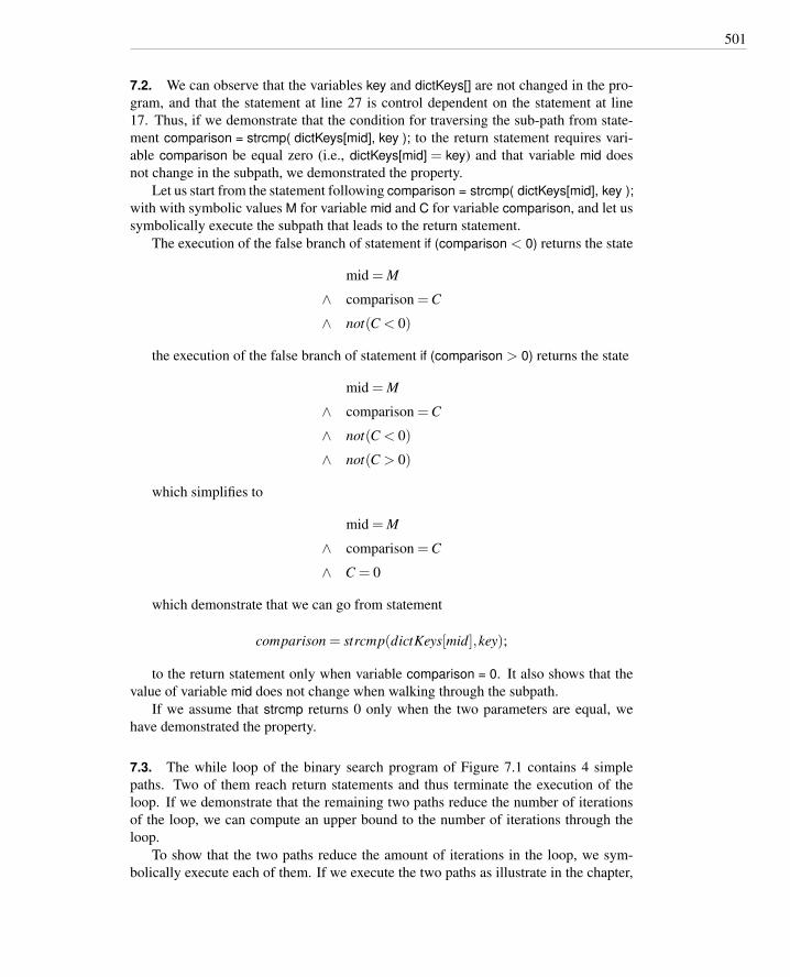
501
7.2. We can observe that the variables key and dictKeys[] are not changed in the pro-gram, and that the statement at line 27 is control dependent on the statement at line17. Thus, if we demonstrate that the condition for traversing the sub-path from state-ment comparison = strcmp( dictKeys[mid], key ); to the return statement requires vari-able comparison be equal zero (i.e., dictKeys[mid] = key) and that variable mid doesnot change in the subpath, we demonstrated the property.
Let us start from the statement following comparison = strcmp( dictKeys[mid], key );with with symbolic values M for variable mid and C for variable comparison, and let ussymbolically execute the subpath that leads to the return statement.
The execution of the false branch of statement if (comparison < 0) returns the state
mid = M
∧ comparison = C
∧ not(C < 0)
the execution of the false branch of statement if (comparison > 0) returns the state
mid = M
∧ comparison = C
∧ not(C < 0)
∧ not(C > 0)
which simplifies to
mid = M
∧ comparison = C
∧ C = 0
which demonstrate that we can go from statement
comparison = strcmp(dictKeys[mid],key);
to the return statement only when variable comparison = 0. It also shows that thevalue of variable mid does not change when walking through the subpath.
If we assume that strcmp returns 0 only when the two parameters are equal, wehave demonstrated the property.
7.3. The while loop of the binary search program of Figure 7.1 contains 4 simplepaths. Two of them reach return statements and thus terminate the execution of theloop. If we demonstrate that the remaining two paths reduce the number of iterationsof the loop, we can compute an upper bound to the number of iterations through theloop.
To show that the two paths reduce the amount of iterations in the loop, we sym-bolically execute each of them. If we execute the two paths as illustrate in the chapter,
502 Solutions to Exercises
starting with symbolic values L and H for variables low and high, we obtain the follow-ing states for the two paths, respectively:
low = L+H2 +1
∧ high = H
∧ mid = L+H2
and
low = L
∧ high = (L+H2 )−1
∧ mid = L+H2
We can thus conclude that each iteration of the loop either terminates (the two pathsthat lead to a return statement) or reduces the distance between the values of variableslow and high by 1
2 (the paths executed symbolically).If we consider that the execution condition of the loop depends only from the rel-
ative values of variables low and high, we can conclude that the iterations of the loopwill terminate when the value of variable low exceeds the value of high, and this hap-pen after a number of iterations sufficient to eliminate the distance between two integervalues iteratively dividing it by a factor of 2, i.e., log2(H−L).
7.4. We can execute the path starting with symbolic values C, L, H and M for variablescomparison, low, high and mid, respectively.
The execution of the false branch of the first if statement leads to the symbolic state:
low = L
∧ high = H
∧ mid = M
∧ comparison = C
∧ not(C < 0)
the execution of the false branch of the second if statement leads to the symbolicstate:
low = L
∧ high = H
∧ mid = M
∧ comparison = C
∧ not(C < 0)
∧ not(C > 0)
the false branch of the third if statement cannot be executed under these conditions,in fact the condition: comparison =C∧not(C < 0)∧not(C > 0) implies comparison =0 and thus prevents the execution of the false branch, which is infeasible.

503
7.5. The precondition must indicate that the array is not empty, as required by thespecification. If we assume that initial value of setSize indicates the size of the array,we will have the term (setSize > 0).
We must also decide if to interpret the word set in a strict mathematical sense, i.e.,without repeated elements, or not. In the first case, we must add the term:
∀i, j 0 ≤ i < j < setSize : set[i] 6= set[ j]
The postcondition must indicate that the result is the index of the maximum value.If we indicate the result with result, the condition can be expressed as:
∀i 0 ≤ i < setSize : set[result]≥ set[ j]
notice that the condition of non-empty set is required for the validity of the pred-icate. Notice also that in case of repeated elements, we do not indicate a privilegedindex as result.
This term can be expressed also as:
∀i 0 ≤ i < setSize, i 6= result : set[result] > set[ j]
but in this case the condition holds only if the set does not contain repeated ele-ments.
The condition should be completed asserting that the result belongs to the array:0 ≤ result < setSize
To avoid undesirable side effects, the postcondition should also state that the set isnot changed by the method:
∀i 0 ≤ i < setSize : set[i] > set’[i]
Chapter 8
8.1. The statements are consistent. A conservative or safe finite state verificationtechnique really is tantamount to formal proof that a certain model has the verifiedproperty when it “succeeds” in the sense of finding no violations of the property. It isless powerful than formal verification, nonetheless, because the properties it can verifyare more limited, the models it can verify those properties against are likewise morelimited, and it may fail (often producing spurious error reports) in cases where a moreexpensive formal verification could have succeeded. In terms of Figure 2.2, page 19,such a technique has no optimistic inaccuracy, but it has greater pessimistic inaccuracy(but less cost) than theorem proving.

504 Solutions to Exercises
8.2. The OBDD for x ⇒ y∨ z is shown below with variable ordering x,y,z.
xF T
F T
yF T
zF T
8.3.
(a) The OBDD is larger when z is first in the variable ordering than when x or y isfirst.
xF T
F T
yF T
zF T
yF T
zF T
xF T
yF T
F T
xF T
yF T
Since x and y appear only together with commutative operations (logical and andor), there is no difference in shape between the OBDD in which x precedes y andthe OBDD in which y precedes x; we can just swap variable labels in the OBDDdiagram.
(b) In the expression(x∨ y∨ z)∧¬(x∧ y∧ z)
the variables always appear together in the same combinations with commutativeoperators (logical and and logical or), so their ordering cannot matter.
8.4. A safety property asserts that “nothing bad happens,” while a liveness propertyasserts that “something good eventually happens.” The real-time property (“within 30seconds”) creates a “bad” thing that can happen, in this case passage of 30 secondsbefore arrival of the elevator.
For readers familiar with Buchi automata, a more formal and precise characteri-zation follows the same outline but characterizes “good things” and “bad things” interms of recognizing infinite strings. Violation of a safety property is recognized by

505
transition to a trap state (once the transition on the “bad thing” is made, no transitionto an accepting state is possible). Violation of a liveness property corresponds to aninfinite loop through a set of non-accepting states. Linear temporal logic (LTL) model-checking tools, including Spin, typically construct and interpret Buchi automata, andviolation of liveness properties are reported as “non-progress cycles.”
Chapter 9
9.1. Transition coverage subsumes state coverage, under the (reasonable) assumptionthat all FSM states are reachable.
Path coverage subsumes transition coverage, under the slightly stronger (but stillreasonable) assumption that all states are reachable on paths from the distinguishedstart state. (A model that violates this assumption is not very useful.)
Path coverage also subsumes state-pair coverage: At least one of the sub-pathsfrom r to s must be covered. However, state-pair coverage does not subsume transitioncoverage, nor vice versa, as illustrated by the following simple example.3
paths
states
transitions state pairs
For this FSM, each of the labeled states is reachable from all other labeled states,so there are 32 = 9 state pairs, including pairs like 〈r,r〉 and 〈s,s〉. All of these statepairs can be covered with one looping path, so we can satisfy the state-pairs criterionwith a test suite containing just one test case:
{〈t1, t3, t4, t1, t3〉}
This test suite does not satisfy the transition coverage criterion, since transition t2is not covered. Therefore state-pair coverage does not subsume transition coverage.
On the other hand, we can satisfy the transition coverage criterion with the follow-ing test suite containing just two test cases:
{〈t2, t4, t2〉,〈t1, t3〉}
This second test suite does not cover several of the state-pairs, such as 〈s,x〉, 〈x,x〉,and 〈x,r〉. Therefore transition coverage does not subsume state-pair coverage.
We conclude that the subsumes hierarchy, for these criteria, is
3We are using notational conventions as in UML statecharts to mark the initial and final state as if startingand ending were special transitions, but they do not correspond to program inputs and so are not consideredin the adequacy criterion.

506 Solutions to Exercises
paths
states
transitions State pairs
9.2. The feasibility of logical conditions is undecidable in general, as long as termsin our specification language are at least rich enough to describe integer arithmetic orsomething equivalent to it. Therefore we cannot escape the infeasibility problem evenwith adequacy criteria based on specifications.
One might reasonably argue, however, that the practical impact of the infeasibilityproblem is smaller with logical specifications, because
• A well-crafted logical specification should be smaller and simpler than the pro-gram it specifies (though this is not always true in practice).
• A test obligation based on a specification is typically a fairly simple combinationof parts of the specification, while the logical conditions under which a programelement executes can be extremely complex.
9.3. We cannot be certain that faults revealed by A are also revealed by B. In fact, asthe question is stated, it is even possible that A also satisfies the stronger criterion C2,or an even stronger criterion C3. Even if we knew that A did not satisfy C2, it wouldnot follow that all the faults revealed by A would also be revealed by B. A might bean exceptionally good test suite for reasons unrelated to the adequacy criterion, or wemight just have been lucky.
Chapter 10
10.1. This aspect of the XP does not contradict the assertion that test cases are aformalization of specifications. On the contrary, in XP the role of test cases as a formof requirements statement is explicit.
10.2.
(a) The fault is revealed if q = 0∧ a = 0; this will be true only if both a and b arezero. The probability of either being zero is 1 in 232. The probability of bothbeing zero is the product of the individual probabilities, 1 in 232 × 232, or 1 in264.
(b) When a is zero, q must be greater than or equal to zero; therefore the fault will berevealed whenever a = 0. The probability of a being zero in a randomly selectedset of values is 1 in 232.

507
10.3. One potential breakdown is to separate the graphical interface, the textual in-terface, and the core functionality. It may be difficult to test core functionality apartfrom one of the interfaces, though. If core functionality is grouped with one of theinterfaces, for practical reasons it is better to group it with the textual interface, keep-ing the graphical interface separate because of the greater expense of producing andinitially executing test cases for the graphical interaction. (Capture and replay toolscan automate re-execution of a test case involving graphical interaction, but manualoperation is typically required the first time a test case involving graphical interactionis executed.)
The core functionality could be further divided into basic arithmetic functions andthe memory functions (including with the memory functions checks that the arithmeticfunctions operate on the the correct values).
Chapter 11
11.1.
(a) If parameter characteristics and value classes are given without constraints, thenumber of test case specifications is the product of the number of value classesin each category. For example, if the categories are A, B, and C, category A has5 value classes, category B has 6, and category C has 3, then the number of testcases is 5×3×6.
(b) If only error and single clauses are used, we just treat value classes with thoseconstraints separately from unconstrained value classes. The number of test casespecifications is the sum of the error and single classes, plus the product of thenumbers of unconstrained value classes in each category. For example, if againthe categories are A, B, and C, and A has 5 values classes, 1 of which is an errorclass, B has 6, 1 of which is an error class and 1 of which is a single class, andC has 3 classes, all unconstrained, then the number of test case specifications is(1+2+0)+(5−1)× (6−2)×3.
(c) First, we separate single and error choices from other parameters. Each single orerror choice contributes exactly one test case (and we do not use them to coverother combinations).
For the remaining enumeration, we consider a set P of parameters (categories)whose remaining choices may have if and if-property constraints. Let N be thenumber of parameters, and let n1 . . .nN be the number of (non-error, non-single)choices in each category P1 . . .Pn.
Our approach is a simple recursive enumeration of possibilities, essentially sim-ilar to what we would use to generate a set of test case specifications. For eachpossible property, we need two flags: One to indicate if the property must bea constraint associated with one of the value choices (because it appears in anif-property constraint associated with another value choice) and another flag toindicate if the property has been indicated in a property constraint on a value

508 Solutions to Exercises
choice.4 We begin with an empty set of constraints, and add to it as we traversea tree of possibilities:
1 /** Count the number of test cases specifications2 * that would be generated from N categories, where3 * the value choices in each category may have4 * ”property p” or ”ifproperty p” constraints (but5 * with no ”single” or ”error” constraints.6 */7 def enumerate( int i, constraints c ) is8 if i > N then9 /* Tuple is complete. Is it consistent? */
10 for each "must p" constraint in c do11 /* Consistent only if another value12 * had property p13 */14 if "has p" not in c then return 0;15 od;16 /* If all the ”ifproperty p” constraints were matched17 * by ”property p” constraints, then the case is ok.18 */19 return 1;20 fi;21 /* Still need to fill in choices for categories i..N.22 * For each choice in category i, we’ll count the ways23 * to fill in categories i+1 .. N.24 */25 count = 0;26 for each choice v in P[i] do27 childConstraints = c;28 for each [property p] constraint on v do29 add "has p" to childConstraints;30 od;31 for each [if p] constraint on v do32 add "must p" to childConstraints;33 od;34 count = count + enumerate ( i+1, childConstraints );35 od;36 return count;37 end enumerate;38
4Note that we cannot be certain of encountering the categories with property constraints before havingto select among choices for another category with corresponding if-property choices. If we could (e.g., ifwe accepted only specifications with parameters that could be sorted so that no property is tested before itis set), then only one flag per property would be needed, and the enumerative algorithm could be somewhatfaster.

509
11.2. No, pairwise coverage will never produce a larger test suite than category par-tition testing, provided properties, constraints, and single and error cases are treatedthe same in both approaches. Both approaches should generate the same number oferror and single cases (though they may choose other values in the single and errortest case specifications differently). For cases made up of normal (that is, not error orsingle) values, every test case specification that can be created by a pairwise combina-torial testing tool is also a combination of values that should be created by the categorypartition testing tool.
11.3.
(a) The value V5 is not possible because it conflicts with V2. The value V6 is notpossible because it conflicts with V3. After eliminating incompatible choicesfrom category C3, there are no choices available.
(b) We should not treat erroneous values as candidates for completing a normal testcase specification. The point of testing each pairing of normal values is to checkfor interactions between particularly pairs, and errror handling is likely to maskany such interaction.
(c) If we marked V7 as single because it is (or should be) treated as a special case,then the same argument applies as in part (b): The single value is a poor choice tocomplete a test case specification. If single has been specified simply to reducethe size of a generated test suite, then we might be willing to relax this rule.One might also reasonably argue, though, that undisciplined use of single is asymptom of sloppy test design, and that it is therefore better to receive a warningabout pairs that cannot be covered than to supporess that warning by overridingthe single constraint.
11.4. Acceptable answers can vary. A good answer should describe parameter char-acteristics, not concrete values. Note, for example, that in our sample solution, timesof the outbound departure are classified by their relation to the inbound arrival, ratherthan being selected from a set of concrete times. The distinction between parametervalues and parameter characteristics may be slight when parameters are orthogonalor nearly so, but becomes important when the specification describes relations amongparameters.
Parameter: Arriving flight
Arriving flight codemalformed [error]not in database [error]valid

510 Solutions to Exercises
Originating airport codemalformed [error]not in database [error]foreign city (relative to transfer airport)domestic city (relative to transfer airport)
Scheduled departure timesyntactically malformed [error]out of legal range [error]legal
Destination airport (transfer airport)malformed [error]not in database [error]valid city
Note: we are using the destination aiport of the first flight as a base for callingother airports “domestic” or “foreign,” so we don’t classify the destination airportitself except as to being domestic or foreign.
Scheduled arrival time (t0)syntactically malformed [error]out of legal range [error]legal
Parameter: Departing flight
Departing flight codemalformed [error]not in database [error]valid
Originating airport codemalformed [error]not in database [error]differs from transfer airport [error]same as transfer airport
Scheduled departure timesyntactically malformed [error]out of legal range [error]before arriving flight time (t0)between t0 and t0 + DCT [if ICT-greater]between DCT and t0 + ICT [if ICT-greater]more than t0 + max(ICT,DCT)equal to t0 + DCTequal to t0 + ICT

511
Destination airport codemalformed [error]not in database [error]foreign city (relative to transfer airport)domestic city (relative to transfer airport)
Here “foreign” means the two cities (transfer airport and destination airport) haveunequal zones, and “domestic” means they have the same zone.
Scheduled arrival time
syntactically malformed [error]out of legal range [error]legal
Parameter: Airport connect time record
This parameter refers to the domestic and international connect time record corre-sponding to the transfer airport.
Domestic connect time (DCT)not found [error]invalid [error]valid
International connect time (ICT)not found [error]invalid [error]not allowedless than domestic [single]same as domesticgreater than domestic [property ICT-greater]
11.5. As in the previous exercise, acceptable answers can vary. Function AirportConnection Check involves two flights which are composed of two airports, a departingand an arrival time. Here we consider only the inputs used by the function. Othersolutions may consider all the details.
New catalog entries The specification refers to universal and connecting time.
Time[in/out] valid[in] invalid
Step 1: Identify elementary items
Validated preconditions
pre-1 arr fl.dest.code is valid
pre-2 dep fl.orig.code is valid
512 Solutions to Exercises
Assumed preconditions
pre-3 arr fl.arr time is a valid universal time
pre-4 dep fl.dep time is a valid universal time
Postconditions
post-1 if arr fl.dest.code == dep fl.orig.code and [(arr fl.dest.zone == dep fl.orig.zone implyarr fl.arr time - dep fl.dep time≥ arr fl.dest.dom conn time) or (arr fl.dest.zone 6= dep fl.orig.zoneimply arr fl.arr time - dep fl.dep time ≥ arr fl.dest.int conn time)], then val code == 0
post-2 if arr fl.arr.code is not in Airport DB, then val code == 10
post-3 if dep fl.dep.code is not in Airport DB, then val code == 10
post-4 if arr fl.arr.zone == dep fl.dep.zone and arr fl.arr time - dep fl.Dep time < arr fl.dest.dom conn time,then val code == 15
post-5 if arr fl.arr.zone 6= dep fl.dep.zone and arr fl.arr time - dep fl.Dep time < arr fl.dest.int conn time,then val code == 15
post-6 if arr fl.arr.code 6= dep fl.dep.code, then val code == 16
post-7 if other error, then val code == 20
Variables
var-1 arr fl is a flight
var-2 dep fl is a flight
var-3 val code is a validity code
Definitions
def-1 flight is a tuple 〈 f l id,orig,dest,dep time,arr time〉def-2 orig is an airport
def-3 dest is an airport
def-4 dep time is a universal time
def-5 arr time is a universal time
def-6 airport is a tuple 〈code,zone,dom conn time, int conn time〉def-7 code is a string of three alphanumeric characters
def-8 zone is a string or two alphanumeric characters
def-9 dom conn time is a connecting time
def-10 int conn time is a connecting time
def-11 validity code can be {0, 10, 15, 16, 20}We do not consider fl id (the flight identifier), since it is not used by the valid connection
function.
Operations none
Step 2: Derive a first set of test case specifications from preconditions, postcon-ditions and definitions

513
Validated preconditions
TC-pre-1.1 arr fl.dest.code: valid code
TC-pre-1.2 arr fl.dest.code: not valid code
TC-pre-2.1 dep fl.orig.code: valid code
TC-pre-2.2 dep fl.orig.code: not valid code
Assumed preconditions no test cases
Postconditions
TC-post-1.1 arr fl.dest.code == dep fl.orig.code and arr fl.dest.zone == dep fl.orig.zone andarr fl.arr time - dep fl.dep time ≥ arr fl.dest.dom conn time
TC-post-1.2 arr fl.dest.code == dep fl.orig.code and arr fl.dest.zone 6= dep fl.orig.zone and arr fl.arr time- dep fl.dep time ≥ arr fl.dest.int conn time
TC-post-1.3 arr fl.dest.code 6= dep fl.orig.code
TC-post-1.4 arr fl.dest.code == dep fl.orig.code and arr fl.dest.zone == dep fl.orig.zone andarr fl.arr time - dep fl.dep time < arr fl.dest.dom conn time
TC-post-1.5 arr fl.dest.code == dep fl.orig.code and arr fl.dest.zone 6= dep fl.orig.zone and arr fl.arr time- dep fl.dep time < arr fl.dest.int conn time
TC-post-1.6 arr fl.arr.code 6= dep fl.dep.code
TC-post-2.1 arr fl.arr.code not in Airport DB
TC-post-3.1 dep fl.dep.code not in Airport DB
TC-post-7.1 other error
We do not explicitly add redundant test cases
Definitions no test cases
STEP 3: Complete the test case specifications using catalogs We use the catalogfrom Table 11.7 augmented with entry time.
Boolean no test cases
Enumeration it applies to def-11 (validity code), but value outside the enumerated setdoes not apply, since validity code is only an output value and all other test cases are redundant
Range L . . .U no test cases
Numeric Constant C no test cases
Non-Numeric Constant C no test cases
Sequence no test cases
Scan with action on elements P no test cases

514 Solutions to Exercises
Time
TC-pre-3.1 arr fl.arr time: invalid time
TC-pre-4.1 dep fl.dep time: invalid time
Chapter 12
12.1. The compound condition adequacy criterion and the modified condition ade-quacy criterion would both be satisfied by the following set of test cases:
Test Case n < max size c = getc(yyin) != EOF c != ’\n’(1) False – –(2) True False –(3) True True False(4) True True True
12.2.
(a) The following set of test case specifications satisfies the MC/DC criterion for thestatement. Underlined values indicate the values covered by each test case, i.e.,the values that modify the decision outcome if changed.
Room Open Close Bar Decision(1) True True False False True(2) True False True False True(3) True False False True True(4) False True False False False(5) True False False False False
Notice that test case specification (4) requires a combination of values for termsOpen, Close and Bar that produces a True result. We can chose combinationswhere only Close is True, or only Bar is True. Other combinations may be possi-ble when considering the expressions as Boolean combinations of uninterpretedterms, but are impossible when we consider the semantic interpretation of thoseterms (see next item).
(b) The compound condition coverage would require all 24 = 16 combinations ofBoolean values, some of which are not compatible with the semantics of theterms occurring in the condition. In particular all combinations where more thanone of the terms Open, Close and Bar is True are impossible, since parseAr-ray[pos] cannot be ‘}’ and ‘{’ and ‘|’ at the same time.
12.3. The number of test cases required to satisfy the modified condition/decisioncoverage criterion (MC/DC) can be calculated by induction on the number of elemen-tary conditions.
If there is only one element, then the minimum and maximum number of test casesrequired is 2, one evaluating to True and one evaluating to False .

515
Suppose the predicate is E1∨E2 (or, in C notation, E1 || E2). Let N1 be the numberof elementary conditions in E1, and let N2 be the number of elementary conditions inE2. Assume (by the induction hypothesis) the number of test cases required to satisfythe modified condition coverage criterion for E1 alone is N1 + 1, and similarly N2 + 1for E2. Let T1 be a test suite which would be adequate for the predicate E1 alone, andlet T2 be a test suite which would be adequate for the predicate E2 alone, and let T1 andT2 each be as small as possible, i.e., N1 +1 and N2 +1 test cases respectively. Now wewill construct a satisfactory test suite T for E by combining T1 and T2.
At least one of the test cases in T1 causes E1 to evaluate to True , and at least oneof the test cases in T1 causes E1 to evaluate to False; T2 likewise contains test casesthat evaluate to True and False for E2, else it would not demonstrate the effect of theelementary conditions.
For each test case in T1, we construct a corresponding test case in T by combiningit with a case from T2 that causes E2 evaluate to False . The overall truth value of E foreach of these constructed test cases is the same as the value of E1 for the correspondingtest case, and pairs of test cases in T1 that showed the effective of elementary conditione in E1 correspond to pairs of test cases that show the effectiveness of e in E. Notethat we can always use the same test case from T2 to extend each of the cases in T1; wenever have to extend some test case in more than one way. We similarly extend the testcases T2 for E, using some test case in T1 that causes E1 to evaluate to False .
The total number of test cases produced by extending cases in T1 and T2 is N1 +N2 +2. However, note that one test case, which evaluates to False for both E1 and E2,has been introduced twice. Removing this redundant test case, the number of test casesrequired to satisfy modified condition coverage for E is N1 +N2 +1 = N +1.
Test cases for E1∧E2 can be constructed similarly, except that we extend T1 and T2with partial truth-value assignments that evaluate to True rather than false.
12.4. Splitting a single node n into a series of nodes and edges n1e1n2e2n3 . . .nk addsk nodes and k edges to the graph, leaving the total e−n+2 unchanged. Therefore thecyclomatic complexity is the same whether the nodes are basic blocks or individualstatements. This is intuitively consistent with the idea of using the cyclomatic numberas a kind of “complexity” measure for program source code.
12.5. The two call graph coverage criteria described in this chapter (procedure entryand exit testing and procedure call testing) are not ordered by the subsume relation.Procedure entry and exit testing requires us to exercise all entry and exit points of theprocedure, while procedure call testing requires us to exercise all entry points of theprocedure in all the actual contexts in which the procedure is used. Let us considera procedure P with two return statements R1 and R2, and suppose P is called fromtwo different points within Q. Some test suites might exercise all entry points in allactual contexts without exercising all exit points (P is called from both places in Q, butalways returns throuugh R1), thus satisfying procedure call testing, but not procedureentry and exit testing. Other test suites can exercise all entry and exit points of theprocedure without calling the procedure in all contexts (all calls from the same pointin Q, with some returning through R1 and some returning through R2), thus satisfying
516 Solutions to Exercises
procedure entry and exit testing, but not procedure call testing.Procedure call testing subsumes procedure entry and exit testing for programs that
do not have multiple exit points, since exercising all entry points in all contexts, exer-cises all entry points and the only exit point.
12.6. The MC/DC criterion will demand an infeasible test case when there is a basiccondition that is always True or always False when evaluated in a larger conditionalexpression. In many cases, one might reasonably argue that such an expression oughtto be simplified, omitting the useless part. However, reasonable defensive program-ming practices may also lead one to use conditions that should always evaluate to thesame value. For example, we might be able to reason from program logic and fromknowledge of the problem domain that a door is closed, and yet choose to test that it isclosed before engaging a motor to move the vehicle, as defense against a future changeelsewhere in the program or in its environment.
Chapter 13
13.1.
(a) all p-use some c-use: A test suite T for a program P satisfies the all p-use somec-use adequacy criterion iff, for each (def, p-use) pair d pu of P, at least onetest case in T exercises d pu, and for each set of (def, c-use) pairs dcu withthe same definition as first element, at least one test case in T exercises dcu.
all c-use some p-use: A test suite T for a program P satisfies the all c-use somep-use adequacy criterion iff, for each (def, c-use) pair dcu of P, at least onetest case in T exercises dcu, and for each set of (def, p-use) pairs d pu withthe same definition as first element, at least one test case in T exercisesd pu.
(b) The two criteria do not differ with respect to covering def-use pairs involvingvariables encoded, decoded, dptr*, digit high, or digit low, since for each defi-nition of those variables, there is at most one c-use and one p-use (see Table13.2).
Variable ok is used only in computational statements (c-uses), while variable cis used only in predicates (p-uses). Thus, the all-c-use some-p-use criterion willrequire the same elements as the all-def-use-pairs criterion with respect to ok,while the all-p-use, some-c-use criterion will permit fewer pairs to be covered.The converse holds for variable c, with the all-p-use, some-c-use criterion requir-ing all def-use pairs and the all-c-use, some-p-use criterion permitting smallertest suites.
Variables eptr and *eptr are used in multiple computational statements and eachis used in two predicates. The all c-uses some p-uses criterion requires coveringall but one def-use pair for each of the two variables, since only one of the twop-uses must be covered. The all p-uses, some c-uses criterion requires covering

517
at least three pairs for each variable: the two pairs that include a p-use and atleast one of the pairs that include a c-use.
13.2. All p-use some c-use, all c-use some p-use, all DU pairs, all DU paths and alldefinitions are related in the following subsumption hierarchy.
all definitions
all c-uses some p-uses
all DU pairs
all DU paths
all p-uses some c-uses
Both “all p-uses some c-uses” and “all c-uses some p-uses” criteria subsume “alldefinitions,” because both criteria include at least one DU pair for each definition.Strictly speaking, the subsume relation does not hold for definitions that do not be-long to any DU pair. However, such definitions represent anomalous situations (usuallyfaults) that can be easily identified and removed statically.
The “all p-uses some c-uses” and “all c-uses some p-uses” criteria select differ-ent subsets of DU pairs and thus neither subsumes the other, as shown in the formerexercise.
The “all p-uses some c-uses” and “all c-uses some p-uses” criteria select subsets ofDU pairs, so they are subsumed by the The “all DU pairs” criterion, which covers allof them.
The “all DU paths” criterion covers all simple DU paths, and thus includes all DUpairs, but a test suite satisfying the “all DU pairs” criterion may not satisfy “all DUpaths” when there is more than one simple path from a definition to a use.
13.3. It would be too expensive to treat each element of the buf data structure as aseparate variable for definitions and uses, so (as with most composite data structures)we will treat it as a single object.
One approach would be to consider definitions and uses in terms of a logical“value” consisting of pos and buf together, even though they are not grouped as a Clanguage struct (the closest C equivalent of records or objects in other languages). It isclear that reading or writing either of these two physical variables is essentially a reador write of this logical value, e.g., setting pos to zero makes the effective content of buf

518 Solutions to Exercises
be the empty string, even though no characters are changed. We would treat buf[pos++]= inChar as both a use and a definition, since it is creating a new logical value from theold logical value. In this program, treating buf and pos together in this way for dataflow testing will have the same effect as data flow testing with respect to pos alone.
If we treat pos and buf as separate variables, the emit function is a use, and thestatement buf[pos++] = inChar can be treated as both a use and a definition, or as adefinition that does not “kill” (in the dataflow analysis sense) preceding definitions.

519
Chapter 14
14.1. Test cases for the FSM specification of Figure 14.2.
(a) Transition Coverage The test cases must collectively traverse each transition atleast once. The following set of test cases satisfy the criterion (States numbersrefer to Figure 14.2)
TC-t1 0 – 2 – 4 – 1 – 0TC-t2 0 – 2 – 4 – 5 – 6 – 0TC-t3 0 – 5 – 7 – 9 – 7 – 8 – 6 – 0TC-t4 0 – 3 – 5 – 8 – 9 – 6 – 0TC-t5 0 – 5 – 9 – 6 – 0TC-t6 0 – 5 – 7 – 5 – 8 – 7 – 9 – 6 –0
(b) Single State Path Coverage The test cases must collectively include each subpaththat traverses states at most once in a path that is exercised. The following treeincludes all subpaths that traverse different states at least once. A set of testcases that contains all subpaths from the root to the leaves of the tree satisfies thecriterion.
returnCmp arrivesCmp arrives
Cmp arroves
unable to rep.
Maint(no warranty)
2
NO Maintenance
0
Wait forpick up
3
Wait for acceptance
4
NO Maintenance
0
Wait for returning
1
Repair(maintenance
station)
5
Repaired6Wait for
component
7Repair
(main head)
9Repair(regional
head)
8
Repair(maint. station)
5
Repair(maint. station)
5
Maint(no warranty)
2
unable to rep.Lack cmp
NO Maintenance
0Repair(maint. station)
5 Repair(regional
head)
8Repair
(main head)
9 Repaired6
Wait for component
7
Invalid No.
Repair(main head)
9Repaired
6
Lack cmpSucc. Rep.
Succ. Rep.
unable to rep.
Pick up
Repair compl.
Pick up
acceptreject
Est. costs
Req. no warr.
Req. Maint/courier
Req. Phone/web
(c) Single transition path coverage must include each subpath that traverses transi-tions at most once. A subpath that traverses both transitions 〈5,7〉 and 〈7,5〉need not be included in a test suite satisfying single state path coverage, since itreaches the same states twice, but such a subpath must be included in a test suitesatisfying single transition path coverage. One possible test case covering sucha subpath is TC-t7:

520 Solutions to Exercises
TC-t7 0 – 5 – 7 – 5 – 7 – 9 – 7 – 9 – 6 – 0
(d) The Boundary Interior Loop Coverage criterion exercises each distinct loop ofthe state machine the minimum, an intermediate, and the maximum or a largenumber of times. This should include covering the loop 〈5,7,5〉 an intermediatenumber of times, which can be accomplished with the test case TC-t8:
TC-t8 0 – 5 – 7 – 5 – 7 – 5 – 7 – 9 – 6 – 0
14.2.
(a) Assuming that implicit transitions are error transitions is equivalent to adding toeach state of the FSM of Figure 14.2, page 248, the transitions not already exitingthat state. Each added transition leads to the the same new error state. To satisfythe Transition Coverage criterion, we need to add a new test case for each newtransition.
(b) If we assume that implicit transitions are self transitions, we can satisfy the Tran-sition Coverage criterion by extending test cases already in the suite with selftransitions. With this approach, we do not need to add new test cases, since selftransitions do not lead to a terminal error state, but leave the state unchanged.
14.3.
(a) A sequence of inputs and observable actions for one version of the finite statemachine should correspond to a sequence of inputs and observable actions for theother. State and transition labels may differ, but we can simply trace equivalentpaths by considering the event sequence. This procedure should always work ifboth versions of the state machine are deterministic. If one or both versions arenondeterministic, a test case for one version may not map uniquely to a test casein the other, although there should be at least one corresponding test case.
(b) A test suite that exercises all transitions in a version of the test suite with fewervariables and more states will also cover all the transitions in the more compactstate machine description with variables. The transformation in part (a) induces amapping from states and transitions in the former model to states and transitionsin the latter, more compact model, and this mapping is onto (surjective).
(c) If we map test cases the other direction, from the more compact state machinemodel to the machine in which more states are distinguished, a test suite thatsatisfies the transition coverage criterion for the former may be transformed to atest suite that does not satisfy the transition coverage criterion for the latter. Forexample, consider this test suite for the compact FSM:
Case state-(input)-state . . .Tc-1 p –(f)– p –(a)– p –(c)– l –(a)– p –(c)– l –(f)– p –(e)– dTc-2 p –(c)– l –(e)– d
Key: (f) = LF, (c) = CR, (e) = EOF, (a) = other character

521
This test suite never makes a transition from state l to state d with empty = True,i.e., it never exercises a scenario in which the file does not end with a carriagereturn or line feed. The corresponding test suite for the original state machinewould not satisfy the transition coverage criterion, because it would not exercisethe transition from state w to state d.
(d) Combining FSM coverage with MC/DC will generate test suites that do not de-pend on the number of explicit states. For example, in the case of transition EOFfrom Gathering to Done, MC/DC requires covering both True and False outcomeof predicate not empty, thus covering the cases represented with two transitionsin the original FSM. For this simple machine, the same effect could be obtainedwith a test suite that covers branches; need and usefulness of more complexstructural coverage criteria like MC/DC depends on the way extra variables areused in state transitions.
Chapter 15
15.1.
(a) The transition coverage criterion for the Statechart of Table 15.1 can be satisfiedby test suites with a single test case that traverses all transitions, for example:
Display Modefull-graphicstext-onlylimited-bandwidth
Test Case TCXselect model(M1)deselect model()select model(M2)add component(S1,C1) from workingConfiguration to workingConfigurationremove component(S1) from workingConfiguration to workingConfigurationisLegalConfiguration()add component(S2,C2) from workingConfiguration to validConfigurationisLegalConfiguration()add component(S1,C3) from validConfiguration to validConfigurationremove component(S1) from validConfiguration to validConfigurationadd component(S3,C4) from validConfiguration to workingConfigurationadd component(S1,C5) from workingConfiguration to validConfigurationremove component(S2) from validConfiguration to workingConfigurationadd component(S2,C6) from workingConfiguration to validConfigurationdeselect model()select model(M2)add component(S2,C2) from workingConfiguration to validConfigurationisLegalConfiguration()
Notice that the structure of the test case depends on the test environment, which

522 Solutions to Exercises
determines whether a configuration is valid. The annotations indicate the as-sumptions for the selected case.
(b) The smaller test suite executes faster than the larger one, but the larger test suiteprovides additional information to localize faults, and reduces the likelihood ofmasking faults. A failure of the only test case indicates a fault somewhere inthe code, while a failure of a simple test case, e.g., TCA of Table 15.1, indicatesthat the fault is probably located in one of the three methods called by the testcase. Moreover, a failure of a method called in a specific state may be maskedby following calls in the big test case.
(c) We can transform the test suite in Table 15.1 into a suite that satisfies the thesimple transition coverage but not the the transition coverage criterion, by sub-stituting test case TCB with:
Test Case TCB′
selectModel(M2)addComponent(S1,C1)addComponent(S2,C2)removeComponent(S1)isLegalConfiguration()
obtained from TCB by removing the first two calls to selectModel(M1) and dese-lectModel(). The new test suite covers all transitions covered by the test suite inTable 15.1, except for transition deselectModel() from workingConfiguration tonoModelSelected, which was covered only by the initial calls of test case TCB.
15.2. To cover “error” transitions, we need to add test cases that cover calls of meth-ods deselectModel(), addComponent(), removeComponent() and isLegalConfiguration()in state noModelSelected, and calls to method selectModel() in both states working-Configuration and legalConfiguration, e.g. by adding the test cases:
Test Case TCErr1addComponent(S1,C1)
Test Case TCErr2removeComponent(S1)
Test Case TCErr3isLegalConfiguration()
Test Case TCErr4deSelectModel(M1)
Test Case TCErr5selectModel(M1)selectModel(M2)
Test Case TCErr6selectModel(M1)addComponent(S1,C1)selectModel(M2)
Since these test cases exercise “error” transitions, we expect that the executionswill reach a final error state and stop. When considering the omitted transitions as“self” transitions, they will not necessarily lead to a terminal state, and thus we need tocomplete the call with a sequence that leads to a terminal state. We can complete theset of test cases of Table 15.1 with the following cases:

523
Test Case TCSel f 1addComponent(S1,C1)selectModel(M1)addComponent(S2,C2)isLegalConfiguration()
Test Case TCSel f 2removeComponent(S1)selectModel(M1)addComponent(S1,C1)addComponent(S2,C2)isLegalConfiguration()
Test CaseTCSel f 3
isLegalConfiguration()selectModel(M1)addComponent(S1,C1)addComponent(S2,C2)isLegalConfiguration()
Test Case TCSel f 4deSelectModel(M1)selectModel(M1)addComponent(S1,C1)addComponent(S2,C2)isLegalConfiguration()
Test Case TCErr5selectModel(M1)selectModel(M2)addComponent(S1,C1)addComponent(S2,C2)isLegalConfiguration()
Test Case TCErr6selectModel(M1)addComponent(S1,C1)selectModel(M2)addComponent(S1,C1)addComponent(S2,C2)isLegalConfiguration()
15.3. Here we have an equivalent and non-equivalent scenario for each of the testcases in Table 15.1.
524 Solutions to Exercises
Test Case TC=A
selectModel(M1)addComponent(S1,C1)addComponent(S2,C2)addComponent(S3,C3)removeComponent(S3)isLegalConfiguration()
Test Case TC 6=A
selectModel(M1)addComponent(S1,C1)addComponent(S2,C2)addComponent(S3,C3)isLegalConfiguration()
Test Case TC=B
selectModel(M2)addComponent(S2,C2)isLegalConfiguration()
Test Case TC 6=B
selectModel(M1)addComponent(S1,C1)addComponent(S2,C2)removeComponent(S1)isLegalConfiguration()
Test Case TC=C
selectModel(M1)addComponent(S1,C2)isLegalConfiguration()
Test Case TC 6=C
selectModel(M1)addComponent(S1,C1)addComponent(S1,C2)removeComponent(S1)isLegalConfiguration()
Test Case TC=D
selectModel(M1)addComponent(S1,C1)isLegalConfiguration()
Test Case TC 6=D
selectModel(M1)addComponent(S1,C1)addComponent(S2,C2)addComponent(S3,C3)isLegalConfiguration()
Test Case TC=E
selectModel(M1)addComponent(S1,C1)addComponent(S3,C3)addComponent(S2,C4)isLegalConfiguration()
Test Case TC 6=E
selectModel(M1)addComponent(S1,C1)addComponent(S2,C2)addComponent(S3,C3)removeComponent(S2)isLegalConfiguration()
15.4. If we are using the equivalent scenarios approach to test a hash table, among theproperties that we will test is that, for distinct keys j and k, the state of the table doesnot depend on whether we first add j with value v and then k with value w, or first addk with value w and then j with value v. Although we might devise scenarios to checkequivalence of behavior without making inspecting the abstract state, it is convenientto be able to write a pair of test cases like the following:

525
Test Case order1T1 = HTable.new()T1.add(“k1”, “v”)T1.add(“k2”, “w”)
Test Case order2T1 = HTable.new()T1.add(“k2”, “w”)T1.add(“k1”, “v”)
The equivalence of the two scenarios could be established by calling an equalmethod that compares the canonical representation of T1 at the end of each test case.
Chapter 16
16.1. Weak mutation “kills” a mutant when a difference between the state of the orig-inal and mutated program is detected, whether or not this difference would eventuallyshow up in program output. Strong mutation succeeds in “killing” a mutation onlywhen program output is different. Therefore, a test case that kills this mutant underweak mutation but not under strong mutation is one that causes some differences ininternal state but eventually produces the same output as the original program.
In the example program, mutation of the first of three if statements has made itidentical in effect to the third if statement. A test case that should return True from thethird if statement, but instead returns True from the first if statement, will therefore killthe mutant under weak mutation but not under strong mutation. If s1 is “cat” and s2 is“caat” we will obtain this outcome, because we cannot observe from the output that theprogram correctly judged that “cat” is within edit distance 1 of “caat” by incorrectlyconcluding that “cat” is transformed to “caat” by substituting one letter for another.
16.2. Weak mutation kills a mutant when it detects inconsistencies in the programstate. The corrupted state invalidates the execution that follows the corruption. Tocontinue to execute safely, we would need to save a consistent state and resume theexecution from it.
16.3. Mutation analysis works with small syntactic differences, which mimic the ef-fects of small design and implementation errors. The competent programmer hypoth-esis states that these are reasonably representative of actual faults found in programs.Rejection of the competent programmer hypothesis would mean that these syntacticvariants are not sufficiently similar to faults produced by programmers. The couplingeffect hypothesis states that a test suite thorough enough to detect all or most of one setof faults is also thorough enough to detect all or most of another set of faults; in par-ticular, a test suite thorough enough to detect all or most faults introduced by programmutation is also thorough enough to detect all or most real program faults introducedby programmers. Mutation analysis could still make sense to the extent that either ofthese two hypotheses held, or each held to some extent. If both were utterly false — ifsyntactic mutants were utterly unrepresentative of real faults, and effective detection ofthese unrepresentative faults indicated nothing about effective detection of real faults— then the approach would be without merit.
16.4.

526 Solutions to Exercises
Invalid: Mutants that are not syntactically correct. For example, we can apply theoperator sdl (statement deletion) to remove the declaration int pos = 0, makinguses of of pos syntactically incorrect.
Valid but not useful: Mutants whose behavior differs in a large fraction of possibleexecutions, so that they are killed almost immmediately even with very weaktest suites. For example the mutant obtained by applying the operator aor (arith-metic operator replacement) to transform the statement pos++, into pos−−, orthe mutant obtained by applying the operator ror (relational operator replace-ment) to transform statement pos>0 into pos<0, will not be useful in gaugingor improving thoroughness of the test suite.
Valid and equivalent: Mutants that cannot be distinguished from the original pro-gram by any execution. For example, we can apply the operator abs (absolutevalue insertion) to replace pos (which is always non-negative) with abs(pos), sothat if (pos > 0) becomes if (abs(pos) > 0).
Valid and non-equivalent: Useful mutants, which are valid and not equivalent to theoriginal program, have behaviors that differ from the original program in onlya small fraction of possible executions. For example the mutant obtained byapplying the operator sdl (statement deletion) to remove the statement if (pos>= BUFLEN−2) fail(”Buffer overflow”); will fail in where the buffer overflowcheck should be triggered, and is therefore useful in determining whether thetest suite includes this important case.
Chapter 17
17.1. Two possible approaches, each appropriate in some circumstances, are finger-prints and on-line comparison.
The fingerprint approach stores a value computed from the output, rather than theoutput itself. Cryptographic hash functions such as MD5, for example, produce a com-pact and seemingly random signature corresponding to an arbitrary length text block,such as a suitable text representation of the output of a trusted implementation. If thesame signature is obtained by applying the cryptographic hash function to the programunder test, with very high probability the complete outputs are identical. It does notmatter whether the hash function is secure in the sense that it is difficult for an adversaryto purposely produce a hash collision, so cheap and common cryptographic hashes areapt to be perfectly adequate even if they are obsolete for applications in computer secu-rity. A weakness of this approach is that a test failure (a difference between computedhashes) provides very little diagnostic information. It does not, for example, indicatewhether the difference between predicted and observed output is small or large, orwhether it appears near the beginning of the output or near the end.
An on-line comparison oracle does not store the output of the trusted alternateversion, but rather runs the trusted version in tandem with the version under test, incre-mentally comparing output as it is produced. All but a small portion of the output can

527
be discarded as soon as it has been used in the comparison. On-line comparison ora-cles avoid some of the shortcomings of fingerprints, and in particular they can providebetter diagnostic information from a failed test case. However, they are considerablymore complex to implement, and require more execution resources (which is seldoma property if the only resources required are memory and computation time, but be-comes more problematic if the necessary resources include an external device such asa robotic arm).
17.2. The “test first” approach associated with extreme programming aligns test ora-cles with program specification by using test cases (which include pass/fail criteria) asa form of specification. In this sense it meets our stated goal of unifying specificationand test oracle. However, it bridges the gap in expressiveness by imposing the limita-tions of run-time checking on the specification statement. Thus the underlying problemof tension between expressiveness and efficient checking has not really gone away, butits cost has been moved from a gap between specification and oracle to a gap betweenthe specification we would prefer to state and the specification we can express throughtest cases.
17.3. Advantages of off-line checks may include:
• A computationally expensive analysis may be performed with limited perturba-tion of the running program.
• The same event log may be used for several different checks.
• Because logs may be retained between runs, it is possible to design a test case thatinvolves more than one execution, e.g., comparing logs produced under differentcircumstances.
• Some problems of on-line self-checks (e.g., retention of “before” values) becometrivial when analyzing a log file.
Advantages of on-line self-checks over off-line log analysis may include:
• Direct access to program state is sometimes much simpler and more efficientthan recording an adequate log record. For example, recording the state of acollection data structure after each operation is likely to be much more expensivethan checking a structural invariant during execution.
• Production of a log record is essentially a side effect of program execution. Logrecording may itself cause program failure, for example when available storagefor log retention is exhausted. If logging is activated for testing and disabled inthe production environment, we have introduced a potentially significant differ-ence between the tested program and the program in use.

528 Solutions to Exercises
Chapter 18
18.1. Local face-to-face meetings are easier to organize. Asynchronous “meetings”(really an exchange of messages) are less dynamic and sometimes less efficient thansynchronous communication, but opportunity for synchronous meetings at a distance(teleconferencing) may be limited by time zone differences (e.g., 8am in Eugene is 5pmin Milan) and are more dependent than local meetings on communication technology(which may range from instant messaging or telephone to video conferencing). Thus,distributed inspection requires careful organization of synchronous and asynchronouswork to use meeting opportunities and support effectively.
Distributed meetings are also more taxing and than face-to-face meetings, and lesseffective at building and maintaining personal relationships among team members,though the gap is likely to narrow as communication technology support improves.Even the best technology support is unlikely to completely erase the difference; forexample, cookies brought in by one team member cannot be effectively shared throughan audio or video link.
On the other hand, local inspection can take advantage only of the personnel at asingle location, while the most appropriate personnel may be distributed across loca-tions. A local inspection meeting in Eugene would not be able to include experts indevice interfacing situated in Milan, and the Milan team would be without the map-ping and geographic information system expertise of their Eugene teammates. Thisis particularly apt to be problematic for inspection of requirements and overall designdocuments, which are typically wider in scope than detailed design and code. Andwhile a face-to-face local meeting may be more effective than meeting at a distancefor team-building, the need for building and maintaining camaraderie may be greaterbetween members across sites, e.g., between test designers in Eugene and Milan.
Because both local and distributed forms of meetings have value and limitations,a hybrid approach may be employed. Simple inspection sessions may be carried outasynchronously by individual inspectors without regard to location, with local localface-to-face meetings for checking complex properties when the necessary expertise isavailable locally, and distributed asynchronous work and synchronous meetings for thechecks that involve experts spread across locations.
18.2.
1. A useful study would focus on the ongoing cost of inspection. Start-up costs ofdesigning the inspection process, acquiring tools, constructing initial checklists,training, etc., are less significant if amortized over the long term, and can beignored in an initial evaluation. The most significant costs by far are human re-source (time spent by people on inspections and preparation for inspections) and,in some cases, impact on project schedule (where difficulty scheduling meetingsleads to a schedule impact out of proportion to the actual time spent on inspec-tion). Time spent in inspection meetings and on particular inspection activities(e.g., individual reading and review) is an incomplete record of cost, but is nottoo difficult to measure in most organizations, and is a reasonable choice for apilot study.

529
While we may anticipate long term benefits like spread of knowledge throughthe organization, we should concentrate on the most unambiguous and easilymeasurable benefits in the pilot study. Faults found in inspection can be counted,and we may characterize them depending on whether and how they would havebeen detected without inspection. We may look for these effects in the numberand kinds of faults found in each stage of testing and in bug reports for a fieldedsystem. We may observe an actual decrease in testing effort, or we may be ableto impute a potential decrease in testing effort if the number and seriousness ofsome class of faults is decreased far enough to justify a reduction in testing forthat class of faults. Where inspection at an early stage reduces faults detectedat a later stage, we can also infer a benefit in the difference between the cost ofearly repair and the much higher cost of repairing that fault later.To quantify benefits of revealing faults that would otherwise remain undiscov-ered until the product is delivered, we need to take into account both the effortsaved in fixing the faults (analogous to the difference between the cost of a faultdiscovered during unit development and test and a similar fault discovered duringsystem test), and the impact on customers. Assessing potential impact on cus-tomers may be difficult to do with much precision and credibility. An alternativeis to characterize the cost of detection in some other manner. For example, if in-spection reveals some deadlocks that would otherwise go uncaught, we could tryto identify the same class of faults with another technique such as model check-ing, and evaluate the benefit of inspection as the difference in effort betweeninspection and the other technique.
2. It is notoriously difficult to perform sound studies of human performance in awork setting. Projects are never identical (particularly in software, which doesnot involve people in the mass duplication portion of manufacturing), individualsand teams are never identical in skills and background, and performance maydepend on novelty and practice. With unlimited resources, we might control forindividual and project variation by having each of several teams perform each ofseveral projects under different conditions.Since we never have the luxury of running each of several real projects sev-eral times, we must try to obtain credible comparison within or across projectsand control as well as possible for confounding effects, knowing that both ap-proaches have certain risks (or “threats to validity”). These include positive andnegative effects of change (the Hawthorne effect, in which novelty leads to ex-pectation and realization of improvement, and learning effects, in which peoplebecome better at an activity through practice and familiarity). We can typicallydo a little better at controlling for these effects across projects than within a sin-gle project, where for example the costs and benefits of inspection might varygreatly between the business logic subsystem and the human interface, and theexperience of an individual with inspection in one part of the system might laterimpact that person’s performance on another part. On the other hand, the costof a project-to-project comparison may be higher, and in smaller organizationswe may seldom have two sufficiently similar projects, with sufficiently similarteams, running concurrently. A typical approach (also imperfect but sometimes
530 Solutions to Exercises
the best we can do, at least initially) is to compare a pilot project to the record ofa similar project in the recent past.
18.3. The cost of inspection can be approximated as the effort required for inspectionand meetings. The cost of an analysis tool includes costs of purchasing, personnel,formalization of properties, execution of analysis and interpretation of results. Thepurchasing cost is the cost of the licences. Personnel cost may derive from the need ofhiring people with specific skills. Formalization cost is the effort to express propertiesas required by the analysis tools. Execution cost is the effort required to execute theanalysis. Interpretation cost is the effort required to interpret the results of analysis andidentify the related faults.
Some costs may be negligible, depending on the analysis. For example, a simplelockset analyzer described in the next chapter does not require specific skills, the def-inition of the properties to be checked is built in the tool and interpretation of errormessages is easy. Thus relevant costs are purchasing and execution. On the other hand,model checkers ask for specific skills that impact on the costs of the personnel involvedin the analysis, require properties to be formalized in a specific way, and results maynot be easily interpreted in terms of source code.
18.4. Variations on the following list are possible. A good solution to this exerciseshould have good justifications for the selected ...
The three classes of tools that can optimize inspection effort are:
Feature Highlighter that scans the checklist and identifies and highlights the part ofthe artifact that correspond to the features and the items currently inspected. Forexample, when using the Java checklist in Table 18.4 at page 346, a FeatureHighlighter would highlight the header of the files, when considering the entryFILE HEADER of the checklist, the footer of the file when considering the entryFILE FOOTER, etc.
A Feature Highlighter reduces the inspection and meeting overhead, and main-tains the focus of the inspectors on the creative aspects of the inspection (checkif items are satisfied and not look for items in the artifact to be inspected).
Result Tracker: A Result Tracker keeps track of the results of the inspection and re-lates them to the inspected artifact. For example, referring to the Java checklist inTable 18.4, a Result Tracker Would indicate the parts of the code that violate theitems of the checklist, and would link them to the comments of the inspectors.
A Result Tracker help both inspector and developers to quickly locate problems,identify faults and keep track of progresses.
Meeting Manager: A Meeting Manager supports meeting organization and execu-tion with features to quickly plan meetings according to the schedules of theparticipants, automatically distribute information required for meetings, meetsynchronously and asynchronously in local or distributed environments.
A Meeting Manager reduces the effort waste in organizing meetings and avoidinconveniences that may derive from distraction.

531
18.5. We can turn on the attention and participation of inspectors by (1) making themactive part of the process and (2) define suitable rewarding mechanisms. Passive partic-ipation of inspectors can be avoided by assigning inspector specific (individual) rolesaccording to their expertise, and giving them responsibility for the assigned roles. Wecan for example identify the expert of some classes of design patterns, who will be incharge of double checking items related to those patterns, and of speaking up whensuch items occur in the artifact to be inspected. The necessity of triggering the dis-cussion according to the assigned role forces inspectors to pay attention to the wholeinspection sessions, and increases active participation in the process. Passive partic-ipation of inspectors to meetings can also be discouraged by rewarding mechanismsthat for example depend on the contribution of inspectors to fault identification. Asoften happens, rewarding mechanisms may bring unexpected side-effects in the overallprocess, and must be carefully evaluated in the specific context.
Chapter 19
19.1. A variety of examples are possible.If we consider only intraprocedural analysis, then one way that lock(l) . . . unlockl
might present extra challenges is by involving control flow, especially with correlationof conditions:
if (i < 20) {lock(l);
}...if (i <= 21) {
x = f(y); // x is variable to be protected}...if (i <= 21) {
unlock(l);}
Because synchronized blocks are syntactic structures, the locking and unlockingoperations they imply cannot be intermixed with conditional control flow in this man-ner, and it is simple to determine that the lock is held everywhere within the block.
Another problem that arises when lock(l) and unlock(l) are not grouped togethersyntactically is that they might not appear in the same procedure (method or function).Rather, the lock is acquired in one procedure, and then control is passed to anotherprocedure which is required to release the lock after accessing the object. For example,code that attempts to implement the two-phase locking protocol to ensure serializabletransactions may acquire a lock for each data item before accessing it, but defer releas-ing those locks until a transaction unit is committed.
19.2. A lock is identified with an object, but it is referenced through a variable, sodetermining whether the same lock is always held at a particular program point re-

532 Solutions to Exercises
quires determining whether the lock variable l in a surrounding synchronized(l) { . . .}always refers to the same object. This can be arbitrarily hard (i.e., undecidable in gen-eral), because the variable binding may be determined through an arbitrarily complexcomputation:
l = f( v, w, x );synchronized(l) {
x = g(v, w);}
19.3. The simplest approach may be to provide a user option to revive all previouslysuppressed error reports. The advantage of simplicity is balanced against the seri-ous disadvantage that this approach is unselective, and lets the user see potentiallyimportant error reports only at the cost of wading through many reports that remainirrelevant. Allowing the user to indicate particular error reports that should no longerbe suppressed does not solve this dilemma, because the user gains no information ifreactivating error reports X, Y, and Z results in seeing error reports X, Y, and Z.
More value may be obtained by letting reactivation be triggered (always, or onlyoptionally) by conditions. For example, when suppressing a particular error report, theuser might be given a chance to provide rationale in the form of a program assertion,and the error report might be revived when violations of the assertion are observed.An approach that would place less burden on the user would be to revive suppressederror reports only when surrounding code has been changed in certain ways. Triggeringchanges could be detected statically (e.g., checking at a statement might be reactivatedif another statement on which it is directly control or data dependent has been changed),or dynamic (e.g., using a run-time analysis tool like Daikon to note that a relevantcondition that used to be always true is now sometimes violated).
19.4. For four variables, with three possible values each, there are (23)4 = 4096 pos-sible tuples of sets of FSM states; each possible value is representable in 12 bits. Thereare 2(34) = 281 possible sets of tuples of FSM states; each set is representable in 81bits, around 7 times as large as the tuples-of-sets representation. Solution times arealso likely to be larger for the sets-of-tuples representation, not only because of morework in each step to manipulate the larger representation, but also because the numberof computational steps is related to the number of different approximations encounteredbefore reaching a final value, which is likely to be much greater for the sets-of-tuplesrepresentation.5
The extra cost of the sets-of-tuples representation buys the ability to correlate valuesof the variables. For example, suppose we were attempting to verify (w∨x)⇒¬(y∨z).Suppose x is sometimes true and y is sometimes true, but they are never true at the same
5When a powerset lattice is used to iteratively find a fixed point solution, the number of steps is propor-tional to the height of the lattice, which is equal to the number of bits in the representation. We can think ofeach refinement to the approximation as flipping at least one bit from zero to one; monotonicity guaranteesthat we never flip bits from one to zero.

533
time. Analysis using the tuple-of-sets representation might encounter the values
〈{False},{True},{False},{False}〉
at some program point, and later encounter
〈{False},{False},{True},{False}〉
at the same program point, and merge them to
〈{False},{False,True},{False,True},{False}〉
The fact that the True values of x and y were encountered at different times is lost, andthe analysis inaccurately reports the possibility of x and y being simultaneously trueand violating the property. The more expensive sets-of-tuples representation avoidsthis inaccuracy.
Given these trade-offs, it is clear that we should prefer the tuples-of-sets represen-tation whenever we do not depend on corrrelating values, but may be forced to usethe sets-of-tuples representation when we require its precision in correlating values. Apractical application arises in lockset analysis, where we sometimes need to know thatread accesses to a variable are protected by at least one of several locks, while writeaccesses are protected by all of those locks.
Chapter 20
20.1. The architectural design will minimize risk to the extent it separates questionsabout particular printers or printer drivers from questions about the behavior of thesoftware. All printing functionality must be through a small subsystem with very well-defined interfaces, both the interface to other parts of the software (call it the clientinterface) and interfaces to printers or printer drivers (call it the printer interface).Moreover, those interface definitions must be independent, meaning that one can ef-fectively make a judgment about correct use of the client interface without referenceto the printer interface, and vice versa. With this decomposition, construction and test-ing of the printing subsystem can be scheduled earlier in the project, and testing withactual printers can begin earlier, long before access to the physical printers becomesa resource bottleneck. If the two interfaces are well-enough specified, risk of findingserious problems when the completed software is tested with actual printers should begreatly reduced.
This modularization is generally in line with good software engineering principles,and should align well with the needs of the development manager. For example, thesame separation of concerns protects the development manager from risks associatedwith requirements changes. However, the degree of specification detail and program-ming discipline required is likely to be more than would otherwise be justified, andsome negotiation and compromise may be required.

534 Solutions to Exercises
20.2. Externalizing software development reduces the control over progress, deliverytime and quality. This leads to risks of missing deadlines and delivery of poor qualitysoftware. We can reduce the impact of these risks by externalizing the development ofmodules with low impact on critical paths, anticipate test and analysis activities, agreewith the external development team on measurable test and analysis activities to beexecuted before delivery, define acceptance test suites to be executed on the deliveredmodules, schedule activities to allow for some extra time to recover from unexpecteddelays.
20.3. The distribution of fault types versus triggers indicates which types of test casesreveal the different classes of faults. Unexpected distribution of fault types vs triggersmay derive from bad design of test cases or erroneous classification of test cases. Iftest cases are badly designed, test designers should add appropriate test cases; if testcases are badly classified, test designers may revise the test documentation, and definean incentive structure to avoid erroneous classifications.
The distribution of fault types versus impact indicates the impact of the differenttypes of faults on the customers. Test designers may revise the plan, so that test casesthat reveal fault types with severe impact are executed early.
20.4. Fault qualifier may be correlated with age and defect type. Test designers cananalyze age versus qualifier to monitor development progresses: an increasing numberof faults due to missing code in base code may for example indicate problems in spec-ifications and design. Test designers may analyze defect type versus qualifier to relatespecific development phases to classes of faults: if for example some defect types relatemostly to missing code, they may derive from poor specifications or design.
Chapter 21
21.1. Failures when attempting to read from an empty file may be violations of valuedomains or of capacity or size limits, caused by implicit assumptions about files. Fail-ures when reading a file containing a syntax error could also be violations of valuedomains, but are probably better classified as missing or misunderstood functionality,since the most likely cause is wrongly assuming that files are always checked beforebeing read, e.g., when generated.
21.2. Thread integration is preferable when we can easily identify self-containedfunctionality that includes many modules, for example, maintenance management,configuration management, customer management, etc. Critical module integrationtesting is preferable when implementation risks are concentrated in particular compo-nents or modules. For example, if we use new technology, e.g., a new middlewarelayer, or if failures may cause severe damage, e.g., in the security kernel.
21.3. If bottom-up portions of the backbone strategy are in places where stubs wouldbe more expensive to build than drivers, and top-down portions are in places where

535
drivers are more expensive than stubs, then the overall cost of producing scaffoldingmay be reduced.
Chapter 22
22.1. Test cases that may serve both during final integration and early system test-ing typically refer to end-to-end behavior checked while integrating subsystems. Forexample, many test cases of the test suite designed for the integration of the humaninterface with the business logic of the Chipmunk Web presence may serve both pur-poses. Such test cases may be be executed with a partially stubbed infrastructure asintegration test cases, and with the whole system as system test cases. For example, wemight define a test case for the “check configuration” functionality of the “build yourown computer” feature, use it to test integration of the user interface, business logic,and database components, and continue using it in early system testing.
Integration-only test cases typically check interactions of internal subsystems thatdo not correspond directly to end-to-end behavior. For example, we might define anintegration test case that involves adding to a computer a component not found in thedatabase, requiring the check configuration function to react robustly to that situation,though the we also ensure with client-side and server-side data validation that the situ-ation can never arise in actual system execution.
System-only test cases check global properties that characterize the system as awhole, but not partial integration of subsystems. This is the case of many nonfunc-tional properties, e.g., performance properties that depend on the behavior of the wholesystem. For example, although we would design module and integration test cases re-lated to response time design goals, the ultimate check of overall response time boundswould be from system-only test cases.
22.2. Testing responsibility should typically be shifted from the development to anindependent quality team when it becomes necessary avoid a predominance of devel-opment over quality issues as time and effort become critical, and pressure on devel-opers mounts. Training issues may also impact the decision: Not all good developersmay have good testing skills or vice versa, so dividing responsibility may simplifyidentification of staff with suitable skills.
Shifting testing responsibility from a development to a quality team becomes cost-effective when test case design does not require deep knowledge of implementationdetails. This usually happens when moving from unit and early integration testingto subsystem and system testing. Thus it is often wise to shift responsibility whenmoving to subsystem integration testing. Quality teams may also be responsible formonitoring early testing performed by developers, e.g., by checking unit test coverageand inspecting the results of early testing.
Shifting testing responsibility to a quality team may be impractical when the sizeof the project or organization is small or the cost of shifting in terms of training on theproduct and the process is higher than the anticipated benefits.

536 Solutions to Exercises
22.3. Properties that cannot be efficiently verified with system testing include thosethat refer to users’ perception, those that refer to unexpected behaviors, and many in-ternal properties. The first category, user perceptions, includes many usefulness prop-erties such as ease of reaching some information or navigating in the application, aswell as some dependability properties, such as mean time between failure and avail-ability, which depend on usage. The second category, unexpected behaviors, includessecurity properties regarding protection of the system from malicious attacks. Thethird category, internal properties, includes maintainability, modularity, etc, which arenot primarily properties of system behavior and for which testing is therefore not theappropriate assessment.
For a property of user perception (e.g., ease of navigation), we try to establish aset of concrete and testable conditions early with usability prototyping and assessment,preferably performed by a human interface team. Some of those conditions may beverified through inspection (e.g., checks for compliance with standards for meaningfullabels and ordering of fields on a screen), and some through automated testing (e.g.,bounds on response latency). The actual usability properties would meanwhile be val-idated in an ongoing series of user assessments, from the earliest interface mock-upsthrough the actual system.
Dependability properties like mean time to failure and availability are statistical innature, and must be measured relative to profiles of actual or presumed usage. Randomtests, distinct from systematic system tests, are generated from usage profiles and usedto derive statistical estimates and confidence.
One can never thoroughly test for response to completely unexpected events, butone can often make useful assessments of likely response to rare and undesired events.Security testing, for example, is always relative to a threat model which gives somecharacteristics of the nature of a possible attack. A combination of inspection, staticanalysis, and testing under extreme or unusual conditions can be used. For security, a“red team” may be employed to devise attacks, enriching the threat model as well asdirectly testing protection.
Internal properties such as modularity and maintainability may be assessed in de-sign and code inspections and, to some extent, with static program analyses (althoughone must avoid confusing proxy measures such as coupling and module size with theactual properties of interest).
22.4. A typical case of resource limitations that impact system more than module orintegration testing is that of some embedded software systems that execute on expen-sive equipment. If, for example, we consider the software that drives an aircraft flightsimulator, we may be able to run most module and integration test cases with a scaf-folding of average complexity, but we may need expensive flight simulator hardwareto run many system tests, and scheduling of system testing may suffer much more thanmodule or unit testing from limited availability of the hardware platform. Similarly,software than runs on large and expensive networks may suffer from resource limita-tions during system testing, but not during module or integration testing. This is thecase, for example, of the software of a mobile phone network that needs a whole net-work for final system testing, but whose modules can be tested with suitable scaffolding

537
and a small or simulated network.
22.5. The property must be checked as part of acceptance and not system testing,since it is refers to qualitative measures that depend on customers’ feelings (“perceive”,“convenient”, “fast”, “intuitive”).
To check the property as part of system testing, we would need to reformulate it re-ferring to quantitative metrics strongly associated with customers’ perception, but thatcan be measured independently from them. To formulate the property in quantitativeterms, we can rely on usability principles that relate measurable characteristics of theinterface to perception and reaction time, e.g., by limiting the choices in each page ofthe Web application, steps required to complete an operation, and response latency.
Each window of the purchasing application must include no more than tenchoices. Choices must be highlighted always with the same style, whichmust conform to W3C guidelines. Users must be able to purchase prod-ucts in any legal configuration in less than 5 steps, where a step involvesinteraction with a single screen layout. Erroneous choices must be sig-nalled explicitly to users and must indicate possible recovery actions. Theresponse time of the application to each user choice must not exceed 100milliseconds under peak traffic, where peak traffic is simultaneous accessof up to 1000 customers.
The reader should notice that the reformulation is not perfectly equivalent to theoriginal property, and do not substitute for a final acceptance testing phase, but allowsmany checks to be performed earlier at interface design time and during subsystem andsystem testing, to reduce testing and rework costs.
Chapter 23
23.1. Some of the possible differences in tooling for each of the pairs of projects arerather obvious, but some less obvious differences are also possible.
• Java-only versus mixed language development: The obvious difference is that wemay have tools specific to each development language. For example, we mightuse one testing framework for Java, and another for Python, even if they pro-vided essentially similar functionality. A more interesting difference is in single-language versus multi-language development — integrating analysis across lan-guages is likely to be a larger challenge than providing analysis for each of thelanguages individually.
• Larger and longer projects require more thorough (and, unavoidably, more bu-reaucratic) process and documentation than shorter, smaller projects. This isequally true for managing the quality process as for managing development ofproduct code. Tool support for the larger project will almost certainly involvecollecting and integrating much more information, in greater detail, than for the

538 Solutions to Exercises
smaller project. Also, the larger project may reasonably make larger invest-ments in tools specialized to that project than would be justifiable for the smallerproject.
• Tooling for the information system will be similar to other information systems.The interesting part of the question is tool support for testing the weather sim-ulation. Test oracles for simulation software pose a challenge in distinguishingcorrect behavior from other, plausible-looking but flawed results. A typical ap-proach to validation is to “predict the past” by running a model of past knownbehavior. This is particularly appropriate for weather simulation, and we wouldexpect a testing framework that allowed replaying of models with past data andcomparison to a record of actual weather in that period.
23.2. One simple approach is to forbid (and scan for) string constants in source code,or string constants of more than n alphabetic characters. A simple script in Awk, Perl,or Lex can be written to perform this check. Since quoted strings might still be neededin some contexts, one could either provide a way to indicate strings that will definitelynot appear in messages, or one could partly automate that task with interprocedural dataflow analysis to distinguish string constants that definitely will, may, and definitely willnot be propagated to user messages.
23.3. Limitations of human memory make us very bad at the sort of mental bookkeep-ing needed to check non-local properties, so automating that check is almost certainlythe better investment. Exceptions are possible, for example if the local property issafety critical and violations of the global property are merely annoying.
Chapter 24
24.1. Agile software development methods prescribe a precise set of test cases thatmust be executed during development. For instance, the sidebar on page 381 requiresexecuting unit and integration test suites at each development step. We can derive ananalysis and test strategy template from the description of our favorite agile method,and instantiate the template for the specific organization or project. (Readers familiarwith a particular agile software method are encouraged to produce an analysis and teststrategy template for that method.)
Some elements of a standard test plan can be derived from the organization of theproject according to the adopted method: items to be verified (all units correspondingto user stories), suspend/resume criteria (usually all tests must be passed, but we mayadopt different criteria in specific cases) and test deliverables (at least the ones thatcan be produced automatically). Other elements may be deduced only partially. Theoverall process includes information about resources and responsibilities, but we mayneed to refine the preliminary information for some methods. Features to be tested,tasks and schedule are partially implied by the method, but may need to be adapted tothe specific situation.

539
A typical test tool, such as JUnit, provides information that could be used to auto-matically produce test suite and test case specifications as well as detailed test reports.It may be useful to add Javadoc comments to link JUnit tests to user stories (and therebyto the test plan). Summary reports may be generated automatically from detailed re-ports.
24.2. To define a tabular specification of a suite of test cases, we can distinguish be-tween information common to the whole suite, and information that characterizes eachtest case. We can keep the information common to the whole suite as ”global informa-tion” outside the table, and we can define a column for each item that characterizes thetest cases.
Referring to the test case specification at page 464, Test Item is common to all thecases of the suite, and can be kept outside the table. All other items vary among testcases and thus will correspond to columns of the table.
We will have simple columns for Test Case Identifier (TC id.), Output Specifica-tion (Output), Environmental Needs (Env. Needs), Special Procedural Requirements(Special Proc. Req.), and Intercase Dependencies (Intercase Dep.)
The input specification will correspond to a set of columns, one for each input item:Model number (Model No.), Number of required slots for selected model (#SMRS),Number of optional slots for selected model (#SMOS), . . . , Number of components inDB (No. Comp. in DB). Each input item is characterized by a Test case specification(Spec) and a Test case (Value), and we will thus have two columns for each of theitems that characterize the input. Some items may not be required: In our example,correspondence of selection with model slots is not necessary, since it can be deducedfrom the other fields, and we thus did not include it in the table.
Even in a more compact format, tables may grow fairly large. Test Designers willtypically use spreadsheets, which can easily accommodate tables larger than a printedpage. On the following page we present the table in two levels to fit the page size.
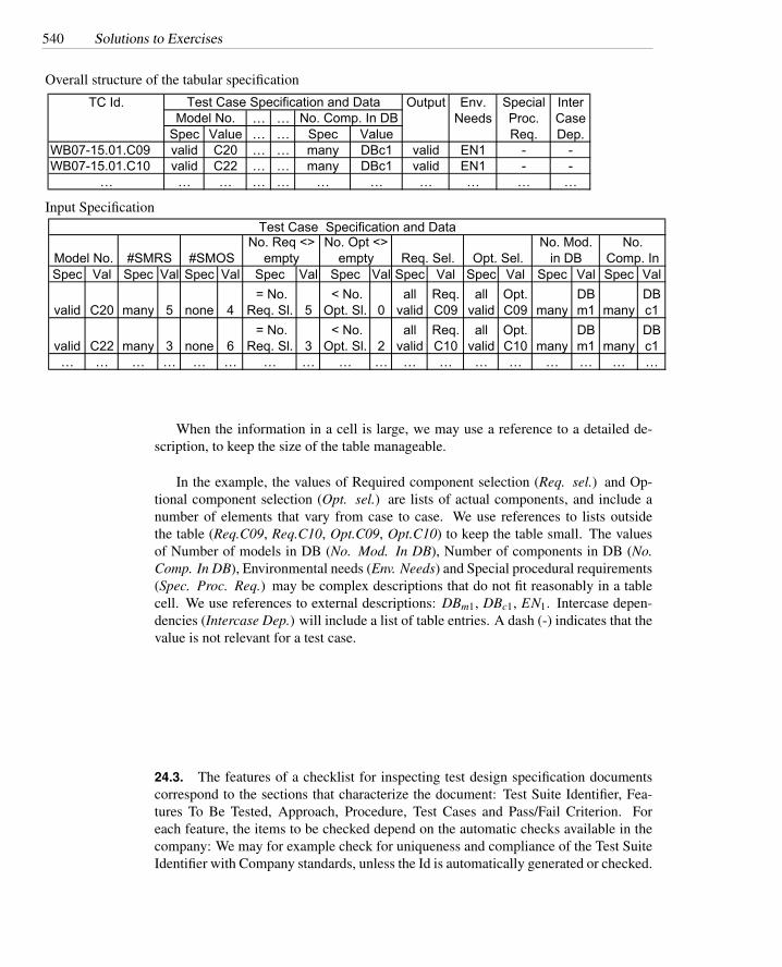
540 Solutions to Exercises
Overall structure of the tabular specification
… …Spec Value … … Spec Value
WB07-15.01.C09 valid C20 … … many DBc1 valid EN1 - -WB07-15.01.C10 valid C22 … … many DBc1 valid EN1 - -
… … … … … … … … … … …
Env. Needs
Special Proc. Req.
Inter Case Dep.
Test Case Specification and DataTC Id. OutputNo. Comp. In DBModel No.
Input Specification
Spec Val Spec Val Spec Val Spec Val Spec Val Spec Val Spec Val Spec Val Spec Val
valid C20 many 5 none 4 = No.
Req. Sl. 5 < No.
Opt. Sl. 0all
validReq.C09
all valid
Opt.C09 many
DBm1 many
DBc1
valid C22 many 3 none 6 = No.
Req. Sl. 3 < No.
Opt. Sl. 2all
validReq.C10
all valid
Opt.C10 many
DBm1 many
DBc1
… … … … … … … … … … … … … … … … … …
Model No. #SMRS
Test Case Specification and DataNo. Mod.
in DBNo.
Comp. In Opt. Sel.#SMOSNo. Req <>
emptyNo. Opt <>
empty Req. Sel.
When the information in a cell is large, we may use a reference to a detailed de-scription, to keep the size of the table manageable.
In the example, the values of Required component selection (Req. sel.) and Op-tional component selection (Opt. sel.) are lists of actual components, and include anumber of elements that vary from case to case. We use references to lists outsidethe table (Req.C09, Req.C10, Opt.C09, Opt.C10) to keep the table small. The valuesof Number of models in DB (No. Mod. In DB), Number of components in DB (No.Comp. In DB), Environmental needs (Env. Needs) and Special procedural requirements(Spec. Proc. Req.) may be complex descriptions that do not fit reasonably in a tablecell. We use references to external descriptions: DBm1, DBc1, EN1. Intercase depen-dencies (Intercase Dep.) will include a list of table entries. A dash (-) indicates that thevalue is not relevant for a test case.
24.3. The features of a checklist for inspecting test design specification documentscorrespond to the sections that characterize the document: Test Suite Identifier, Fea-tures To Be Tested, Approach, Procedure, Test Cases and Pass/Fail Criterion. Foreach feature, the items to be checked depend on the automatic checks available in thecompany: We may for example check for uniqueness and compliance of the Test SuiteIdentifier with Company standards, unless the Id is automatically generated or checked.

541
FEATURES (where to look and how to check):item (what to check)
TEST SUITE IDENTIFIER: is the ID ...? yes no commentscompliant with Company standardsunique
FEATURES TO BE TESTED: is the feature ...? yes no commentsclearly identified or specified
APPROACH: is the approach...? yes no commentsclearly specifiedcompliant with applicable test strategy and standardsappropriate for application domain and feature to betestedapplicable with the available tools and knowledge
PROCEDURE yes no commentsprocedure is executableprocedure is automated to the extent possibledescription is unambiguousdescription is complete and self-contained
TEST CASES: does the set of test cases satisfy the following properties? yes no commentsmeets criterion imposed by the test approach
PASS/FAIL CRITERION: is the criterion ...? yes no commentscompliant with applicable strategy and standardsunambiguouseasily verifiable
Checks on single test cases do not belong to this checklist, but to a checklist for testcase specification documents.
The checklist does not includes checks of sections common to all technical docu-mentation (Title, Approval, History, Table of Contents, Summary, etc), which belong toa general checklist for inspecting documents and not to a checklist to inspect a specificclass of documents. (In some cases, general and specific checklists may be merged ina single checklist for practical purposes, but the checklists are conceptually distinct).
24.4. Some design decisions and considerations include
1. A single top-level repository or multiple repositories?
Distributed development (Milan and Eugene) suggests posssibly using dis-tinct top-level CVS repositories, which are more difficult to manage but mayavoid performance and availability issues for distant users. The choicemay depend on whether other aspects of the repository organization tendto break down along geographic lines. We could even choose to arbitrar-ily divide the repository along geographic lines (all Milano-based artifactsin one repository, and all Eugene-based artifacts in another, regardless ofdocument kind or role), but this is likely to conflict with other considera-tions.

542 Solutions to Exercises
2. Break down by artifact kind (e.g., design document versus source code) or bysubsystem (e.g., business logic versus Web interface)? There will be breakdownby several criteria, but which divisions are subordinate to which others?
Where two sub-hierarchies should mirror each other (e.g., unit test suitesassociated with source code units), it is helpful for them to be near eachother in the organization; inconsistencies are harder to avoid and repairwhen they involve parts scattered throughout the organization.
3. Separate sub-hierarchies for documentation in each language, or one hierarchyof documents with different language versions kept together.
This decision has elements of the previous one. It is likely that the or-ganization of documents mirror each other (e.g., chapter 3 of the English-language user manual probably corresponds to chapter 3 of the Italian usermanual), which suggests keeping them close together in the organization.
Other design choices and considerations are also possible.