Embed Size (px)
Citation preview

DECEMBER 2004 IEEE Robotics & Automation Magazine 791070-9932/04/$20.00©2004 IEEE
bandoned mines pose significant threats to society,yet a large fraction of them lack accurate maps.This article discusses the software architecture ofan autonomous robotic system designed toexplore and map abandoned mines. A new set
of software tools is presented, enabling robots to acquire mapsof unprecedented size and accuracy. On 30 May 2003, ourrobot “Groundhog” successfully explored and mapped a maincorridor of the abandoned Mathies mine near Courtney,Pennsylvania. This article also discusses some of the challengesthat arise in the subterranean environments and some the dif-ficulties of building truly autonomous robots.
In recent years, the quest to find and explore new, unex-plored terrain has led to the deployment of more and moresophisticated robotic systems, designed to traverse increasinglyremote locations. Robotic systems have successfully exploredvolcanoes [5], searched meteorites in Antarctica [1], [44], tra-versed deserts [3], explored and mapped the sea bed [12], andeven explored other planets [26]. This article presents a robotsystem designed to explore spaces much closer to us: aban-doned underground mines.
According to a recent survey [6], “tens of thousands, per-haps even hundreds of thousands, of abandoned mines existtoday in the United States. Not even the U.S. Bureau ofMines knows the exact number, because federal recording ofmining claims was not required until 1976.” Shockingly, weare unaware of the location of many mines; despite the factthat most mines were built just a few generations ago! A
Software Architecture of an Autonomous Robotic System
©E
YE
WIR
E
BY SEBASTIAN THRUN, SCOTT THAYER, WILLIAM WHITTAKER,CHRISTOPHER BAKER, WOLFRAM BURGARD, DAVID FERGUSON, DIRK HÄHNEL, MICHAEL MONTEMERLO, AARON MORRIS, ZACHARY OMOHUNDRO, CHARLIE REVERTE, AND WARREN WHITTAKER
A

IEEE Robotics & Automation Magazine DECEMBER 200480
recent near-fatal accident in Somerset, Pennsylvania, speaks tothis end: When miners in their routine work accidentallybreached a nearby abandoned mine, 50 million gallons ofwater poured upon them, cutting off nine miners and almostburying them alive. The cause of this accident was officiallydetermined to be a lack of accurate mine maps; the breachedand flooded mine had been suspected to be several hundredfeet away [35].
Even if accurate mine maps exist, those are usually justidealized two-dimensional (2-D) drawings. Little can beinferred from such sketches with regard to critical measures,such as the volume and the structural soundness of an aban-doned mine. Accurate models of abandoned mines would beof great relevance to a number of problems that directly affectthe people who live or work near them. One is subsidence:structural shifts can cause collapse on the surface above.Ground water contamination is another problem of greatimportance; and knowing the location, volume, and condi-tion of an abandoned mine can be highly informative in plan-ning and performing interventions. Accurate volumetric mapsare also of great commercial interest. Knowing the volume ofthe material already removed from a mine is of critical interestwhen assessing the profitability of remining a previouslymined mine.
Abandoned mines are usually not accessible to people.Lack of structural soundness is one reason; another is theharshness of the environment (e.g., low oxygen levels orflooding) and the danger of explosion of methane, a gas thatfrequently accumulates when mines are no longer ventilated.This makes mines a superb target domain for autonomousrobots. However, mapping a mine with a robotic vehicle is achallenge. The vehicle must be rugged enough to survive theharsh environmental conditions inside the mine; it must beable to perceive and negotiate major obstacles. Unfortunately,existing wireless communication techniques are unfit for
mines, so the robot must operate autonomously.This article reports experiments with a robotic system
designed to autonomously explore and acquire three-dimen-sional (3-D) maps of abandoned mines. A detailed descriptionof the hardware for the 1,500 pound vehicle, nicknamed“Groundhog” (Figure 1) can be found in [2]. Groundhog isessentially built out of the front halves of two all terrain vehi-cles (ATVs), endowing it with identical steering mechanismson either end. While the exact configuration of the robotvaried from experiment to experiment, in its final configura-tion, Groundhog was essentially symmetrical, enabling it toretract without having to turn around. For acquiring 3-Dmaps, Groundhog is equipped with tiltable SICK laser rangefinders on either end. It also carries two mine-certifiedportable gas detectors to enable it to detect methane andother combustible gases. To navigate, Groundhog analyzeslocal 3-D scans with regard to traversibility. A fast configura-tion space (C-space) planner determines whether the terrainahead can be negotiated, and if so, identifies suitable paths.Those are then executed via PD control, using fast 2-D scanmatching to keep the vehicle localized. Failure to find a suit-able path leads Groundhog to retract in reverse motion.
Groundhog’s development began in the fall of 2002.Approximately a dozen test runs were carried out in a well-maintained inactive coal mine accessible to people: theBruceton Research Mine located near Pittsburgh, Pennsylva-nia. Mining was discontinued in the early 1940s, but sincethat time, the mine had been maintained in a state safe forpeople to enter. The mine features hallways several hundredmeters long, putting to a test the vehicle’s physical enduranceand its ability to manage large amounts of data. However, thismine is technically not abandoned and, therefore, not subjectto collapse and deterioration. On 27 October 2002, Ground-hog descended for the first time into an abandoned mineinaccessible to people. This mine, the Florence Mine near
Figure 1. (a) The Groundhog robot is a 1,500 pound custom-built vehicle equipped with onboard computing, laser range sensing,gas and sinkage sensors, and video recording equipment. (b) Testing the system inside the Bruceton Research Mine, a well-main-tained mine accessible to research teams.

DECEMBER 2004 IEEE Robotics & Automation Magazine 81
Pittsburgh, had been abandoned and flooded for manydecades. Before the robot’s entry, the mine was mostlydrained, leaving behind acidic mud that miners refer to as“yellow boy.” Figure 2 depicts the vehicle after descendingapproximately 30 meters into the mine, operating on a tetherand under remote control. On May 30, 2003, after a longseries of test runs carried out in the Bruceton Research Mine,Groundhog finally entered an inaccessible abandoned mine infully autonomous mode. The mine is known as the Mathiesmine and is located in the same geographic area as the othermines. The core of this surface-accessible mine consists of two1.5 km long corridors, which branch into numerous side cor-ridors and are accessible at both ends. This was an importantfeature of this mine, as it provided natural ventilation andthereby reduced the chances of encountering combustiblegases inside the mine. Figure 3 depicts both portals of themine. A map of the mine, provided to us by the Mine Safetyand Health Administration and the mine owner, is shown inFigure 4; apparently this is the most accurate map on recordfor this mine. To acquire a more accurate map of one of themain corridors, the robot was programmed to autonomouslynavigate through the corridor. 308 meters into the mine, therobot encountered a broken ceiling bar draping diagonallyacross its path. The robot made the correct decision to retract.
The data acquired on these runs has provided us withmodels of unprecedented detail and accuracy, of subterraneanspaces that may forever remain off limits for people. This arti-cle provides a comprehensive description of Groundhog’s soft-ware architecture. It offers visualizations of 2-D and 3-D mapsof some of the mines mapped by the vehicle. We discuss someof the shortcomings of the present system and lay out a roadmap to future research based on the challenges that remain.
Chassis and ElectronicsGroundhog’s chassis unites the front halves of two ATVs,
Figure 2. On 27 October 2002, Groundhog was deployed intothe Florence mine near Pittsburgh. This experiment is a first ina series in which the robot navigates an environment inacces-sible to people, but still under remote control.
Figure 3. On 30 May 2003, Groundhog enters the Mathies mine near Courtney. For the first time, Groundhog operates in fullyautonomous mode, beyond the reach of our wireless communication link. It autonomously descended 308 meters into the minebefore making the correct decision to turn around after sensing a nonnegotiable ceiling beam draped diagonally across therobot’s path. These photographs show the two entrances to the mile-long corridor system.

IEEE Robotics & Automation Magazine DECEMBER 200482
allowing all four of Groundhog’s wheels to be both driven andsteered. The two Ackerman steering columns are linked inopposition, reducing Groundhog’s outside turning radius toapproximately 2.44 m. A hydraulic cylinder drives the steeringlinkage, with potentiometer feedback providing closed-loopcontrol of wheel angle. Two hydraulic motors coupled into thefront and rear stock ATV differentials via 3:1 chain drives resultin a constant 28.5 0.145 m/s velocity. When in motion,Groundhog consumes upwards of 1 kW, where processing andsensing only draw 25 W and 75 W, respectively. Therefore,time spent sensing and processing has minimal impact on theoperational range of the robot. The high power throughput,combined with the low speed of the robot, means thatGroundhog has the torque necessary to overcome the railways,fallen timbers, and other rubble commonly found in aban-doned mines. Equipped with six deep-cycle lead-acid batter-ies, and in later experiments with eight such batteries,Groundhog has a locomotive range greater than 3 km.
Mine safety regulations require that all electronics either beintrinsically safe or be encased in an explosion proof enclosure.An intrinsically safe device may not, through capacitance orinductance, discharge enough energy into a spark to ignite anexplosive atmosphere. Groundhog’s enclosure is designed toprevent an interior explosion from transferring enough energyto the external environment to trigger an explosion of thatenvironment. To satisfy this requirement, Groundhog was fit-ted with a 225 kg steel enclosure. To compensate for this loadand keep the ground clearance of the robot above 25 cm, thesuspension was re-mounted in a precompressed configuration.
The explosion-proof enclosure houses a 24 Vdc, 90 A,electric motor that drives the pump for the hydraulic system.The 300 MHz PC/104+ CPU and associated I/O electronicsalso occupy the enclosure along with the hydraulic manifoldand its six solenoid actuators. All outgoing power lines arecomputer-controlled and individually fused on both the posi-tive and negative terminals. In addition to being able toexplicitly cut power to external devices, Groundhog’s CPU isequipped with a watchdog timer that automatically disablesexternal power in the event of a computer failure.
Coal mine corridors average 1–2 m tall and 3–6 m wide.At 1 m tall and 1.2 m wide, Groundhog is able to operate inall but the shortest of coal mines with room to maneuver inall but the thinnest. The original dimensions of Groundhogwere engineered to accommodate the constraints at thebreach between the Quecreek and Saxman mines. Thisbreach was 2 m wide by 1.2 m tall, 1.2 m deep, with a 30 cmstep on either side. While Groundhog was denied the chanceto explore this breach, the configuration and dimensions cho-sen have proven effective in the experiments reported here.
In Groundhog’s landmark exploration of the Matthiesmine, which was our only experiment so far in which therobot was truly autonomous, the worst-case scenario was forGroundhog to traverse almost the whole 1.5 km, then have totraverse an additional 1.5 km back out of the mine, for a totalof 3 km, which was determined to be within the operationalrange of the robot. Periodic messages were sent to the base ofoperations via a simple user datagram protocol (UDP) broad-cast message over an 802.11 wireless link, indicating that therobot was alive and working.
Simultaneous Localization and MappingThe core of the Groundhog navigation system is comprised ofa software package that solves the simultaneous localization andmapping (SLAM) problem by acquiring 2-D maps. TheSLAM problem [11] arises when a vehicle attempts to build amap while simultaneously localizing itself relative to this map.On the surface, mobile robots can often use a global position-ing system (GPS) to acquire absolute position information.Underground, we do not have the luxury of GPS localization.
At the lowest level of processing, Groundhog’s mapping sys-tem uses a real-time scan matching technique for registeringconsecutive scans [16], [19]. Scans are acquired using a laserrange finder pointed forward. As is common in the scan regis-tration literature, our algorithm aligns scans by iteratively iden-
Figure 4. The best existing map on record of the Mathiesmine. It shows, at the center, two parallel vertical corridors, ofwhich the robot entered the left corridor from the supply yardend shown towards the bottom. This map is obviously incor-rect: the two corridors do not connect properly towards thetop of this map.
DECEMBER 2004 IEEE Robotics & Automation Magazine 83
tifying nearby points in pairs of consecutive range scans. It thencalculates the relative displacement and orientation of thesescans by minimizing the quadratic distance of all pairs of points[7]. In our implementation, all calculations are carried out inreal-time at 75 Hz, the data rate of the SICK scanner [19].
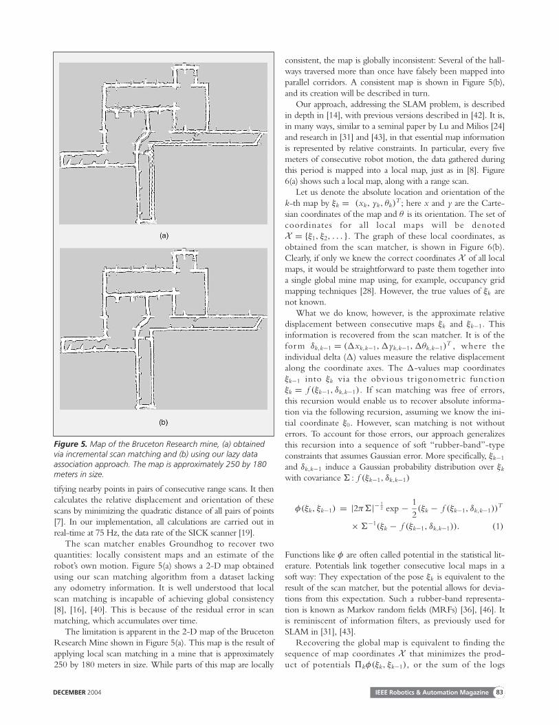
The scan matcher enables Groundhog to recover twoquantities: locally consistent maps and an estimate of therobot’s own motion. Figure 5(a) shows a 2-D map obtainedusing our scan matching algorithm from a dataset lackingany odometry information. It is well understood that localscan matching is incapable of achieving global consistency[8], [16], [40]. This is because of the residual error in scanmatching, which accumulates over time.
The limitation is apparent in the 2-D map of the BrucetonResearch Mine shown in Figure 5(a). This map is the result ofapplying local scan matching in a mine that is approximately250 by 180 meters in size. While parts of this map are locally
consistent, the map is globally inconsistent: Several of the hall-ways traversed more than once have falsely been mapped intoparallel corridors. A consistent map is shown in Figure 5(b),and its creation will be described in turn.
Our approach, addressing the SLAM problem, is describedin depth in [14], with previous versions described in [42]. It is,in many ways, similar to a seminal paper by Lu and Milios [24]and research in [31] and [43], in that essential map informationis represented by relative constraints. In particular, every fivemeters of consecutive robot motion, the data gathered duringthis period is mapped into a local map, just as in [8]. Figure6(a) shows such a local map, along with a range scan.
Let us denote the absolute location and orientation of thek-th map by ξk = (xk, yk, θk)
T ; here x and y are the Carte-sian coordinates of the map and θ is its orientation. The set ofcoordinates for all local maps will be denotedX = {ξ1, ξ2, . . . }. The graph of these local coordinates, asobtained from the scan matcher, is shown in Figure 6(b).Clearly, if only we knew the correct coordinates X of all localmaps, it would be straightforward to paste them together intoa single global mine map using, for example, occupancy gridmapping techniques [28]. However, the true values of ξk arenot known.
What we do know, however, is the approximate relativedisplacement between consecutive maps ξk and ξk−1. Thisinformation is recovered from the scan matcher. It is of theform δk,k−1 = (�xk,k−1,�yk,k−1,�θk,k−1)
T , where theindividual delta (�) values measure the relative displacementalong the coordinate axes. The �-values map coordinatesξk−1 into ξk via the obvious tr igonometr ic functionξk = f (ξk−1, δk,k−1). If scan matching was free of errors,this recursion would enable us to recover absolute informa-tion via the following recursion, assuming we know the ini-tial coordinate ξ0. However, scan matching is not withouterrors. To account for those errors, our approach generalizesthis recursion into a sequence of soft “rubber-band”-typeconstraints that assumes Gaussian error. More specifically, ξk−1
and δk,k−1 induce a Gaussian probability distribution over ξk
with covariance � : f (ξk−1, δk,k−1)
φ(ξk, ξk−1) = |2π�|− 12 exp − 1
2(ξk − f (ξk−1, δk,k−1))
T
× �−1(ξk − f (ξk−1, δk,k−1)). (1)
Functions like φ are often called potential in the statistical lit-erature. Potentials link together consecutive local maps in asoft way: They expectation of the pose ξk is equivalent to theresult of the scan matcher, but the potential allows for devia-tions from this expectation. Such a rubber-band representa-tion is known as Markov random fields (MRFs) [36], [46]. Itis reminiscent of information filters, as previously used forSLAM in [31], [43].
Recovering the global map is equivalent to finding thesequence of map coordinates X that minimizes the prod-uct of potentials �kφ(ξk, ξk−1), or the sum of the logs
Figure 5. Map of the Bruceton Research mine, (a) obtainedvia incremental scan matching and (b) using our lazy dataassociation approach. The map is approximately 250 by 180meters in size.

IEEE Robotics & Automation Magazine DECEMBER 200484
�k log φ(ξk, ξk−1).The key advantage of the MRF repre-
sentation is that it encompasses the resid-ual uncertainty in local scan matching.This enables us to alter the shape of themap in accordance with global consisten-cy constraints. Suppose we know that thek-th map overlaps with some mapj < k − 1, acquired at an earlier point intime, and suppose we have a good esti-mate of the relative displacement betweenthese maps. To incorporate this into theglobal map definition, we define a poten-tial φ(ξk, ξ j) between the coordinates ofthose maps ξk and ξ j. This potential, orconsistency constraint, is of the sameform as the local constraints in (1), butusually with a tighter covariance �. Byadding this potential φ(ξk, ξ j) to the setof potentials, we softly enforce the known displacementbetween ξk and ξ j. Thus, the language of potentials is richenough to add additional nonlocal constraints that can improvethe global consistency of the map.
For any fixed set of potentials � = {φ(ξk, ξ j)}, whichincludes both the original potentials between consecutivemaps and the new potentials, the resulting MRF is describedthrough the following function. This function can be thoughtof as a nonnormalized probability over the joint global loca-tions of all submaps:
p (X ) ∝∏
k, j
exp − 12(ξk − f (ξ j, δk, j))
T
× �−1(ξk − f (ξ j, δk, j)), (2)
where X = ξ1, ξ2, . . . is the set of all map poses. The globalmap is now recovered by minimizing this expression over thethe locations X of all submaps. The negative log-likelihood−log p(X ) is quadratic in the ξ and f -values, but the factthat f is nonlinear makes it impossible to minimize thisexpression in closed form. The classical approach to minimiz-ing such functions is to approximate f by its Taylor expan-sion. This turns −log p(X ) into a quadratic function over thevariables X . Setting the first derivative to zero yields thedesired minimum in closed form, as described in more detailin [17]. We also note that there are a number of alternativetechniques for minimizing −log p(X ), some of which exploitthe sparse nature of the potentials [15], [30], [45].
Data AssociationThe remaining question for building consistent maps is wheredo the consistency constraints come from? Clearly, theapproach described thus far leads only to a consistent global
map when the constraints φ(ξk, ξ j), obtained after loop clo-sure, are qualitatively correct.
Finding the correct consistency constraints is an instanceof a more general problem known as the data associationproblem [4], [10]. The data association problem comesabout when a robot has to decide whether two measure-ments, taken at different points in time, correspond to the
Figure 6. (a) Example of a local map and a single 2-D range scan. (b) The resultingMarkov random field: Each node is the center of a local map, acquired when tra-versing the Bruceton Research Mine near Pittsburgh.
Figure 7. Example of our data association technique: Whenclosing a large loop, the robot first erroneously assumes theexistence of a second, parallel hallway. However, this modelleads to a gross inconsistency, as the robot encounters a corri-dor at a right angle. At this point, our approach recursivelysearches for improved data association decisions, arriving atthe map shown in (b).
Direction of Travel
Direction of Travel
3 (Conflict)
1 (Start)
2 (Cycle)
(a)
(b)
Map After Adjustment

DECEMBER 2004 IEEE Robotics & Automation Magazine 85
same object. The scan matcher already addresses the data asso-ciation problems when aligning scans. However, here the spa-tial error between consecutive scans is typically small, andsimple heuristics such as nearest neighbor work well [7].When closing loops, however, the error may be large, andnearest neighbor may be misleading. Such a situation is shownin Figure 7(a), where a localization error induces a data associ-ation error which, in turn, leads to a broken map. Theimportance of this problem has been pointed out by a num-ber of authors, who have proposed a flurry of techniques forhandling them [8], [13], [18], [27], [38]. The importance ofrobust data association cannot be overemphasized. Minesoften contain numerous loops. Mismapping even a single loopcan have a devastating effect on the overall map, and as a
result, the vehicle may get lost in the mine and never return.Our approach performs likelihood maximization through
a lazy search of the data association tree. The data associationtree is a tree of all discrete data association decisions that canbe made when building a global map; its size is exponentialon the length of the data sequence. An example tree isvisualized in Figure 8(a), which depicts the sequential dataassociation process as new local maps are being acquired.For each new map, a decision is to be weather to introducea consistency constraint, and what the value of this con-straint may be. A consistency constraint is introduced if themap overlaps, with sufficient probability, with a previouslyacquired local map. Localizing the new local map relative tothis previous map, however, may yield more than just one
Figure 8. Searching the data association tree. (a) The tree and a path chosen by locally determining the most likely data associa-tion. (b) The associated log-likelihoods. The arrow indicates an opportunity to increase the log-likelihood by revising past dataassociation decisions. (c) The result of the search for an improved data association, which provides a map of increased likelihood.
5
6
7
8
( 1, 2)
= a?
= c?
= b?
(a)
6
2
44
1
= d?
3
ξ
ξ
2
4
5
7
8
666 6
5
4
log p = −2
log p = −4
log p = −6
log p = −8
log p = −200log p = −10
log p = −12
log p = −300log p = −28
log p = −26
log p = −24
log p = −22
log p = −20
log p = −200
(c)
log p = −2
log p = −4
log p = −6
log p = −8
log p = −200
log p = −300
log p = −12
log p = −10
log p = −20
(b)
1
1
2
3
4 4
5
6 6
7
8
3
8
7
ξξ ξ
ξ
ξ
ξ ξ
ξ
ξ ξ
ξ
ξ
ξ
ξ
ξ
ξ
ξ
ξ ξ
ξ
ξ ξ
ξ
ξ ξ
ξ
ξ
ξ ξ
ξ
ξφ
( 2, 3)ξ ξφ
( 1, 4)ξ ξφ( 1, 4)ξ ξφ
( 4, 5)ξ ξφ
( 3, 4)ξ ξφ
( 6, 2)ξ ξφ ( 6, 2)ξ
ξξ
ξ
ξ
ξφ( 5, 6)ξ ξφ
( 6, 7)ξ ξφ
( 7, 8)ξ ξφ

IEEE Robotics & Automation Magazine DECEMBER 200486
possible alignment, and each such alignment may give riseto a different value for the relative displacement between thecorresponding maps. In Figure 8(a), such a decision is madefor map ξ4, and then again for map ξ6. The map ξ4 overlapswith map ξ1, and localizing ξ4 relative to ξ1 leads to twopossible displacements, labeled a and b in this diagram. Theconstraint that maximizes the log-likelihood function hap-pens to be b in this example, so the corresponding con-straints φ(ξ1, ξ4) = b is added to the set of constraints.Similarly, ξ6 overlaps with ξ2, and d appears to be the morelikely value of the resulting constraint. The gray path in Fig-ure 8(a) illustrates the resulting sequence of data associationdecisions and the affiliated potentials.
However, maximum likelihood data association is proneto errors, and sometimes such errors become only evident inretrospect. An example of this, taken from actual mine data,is depicted in Figure 7(a): The misalignment happens whenthe cycle is first closed, at the location labeled “2” in Figure7(a). However, the inconsistency caused by this misalignmentis not detected until the robot reaches the end of the corri-dor, labeled “3” in that figure. Figure 8(b) illustrates such asituation in the data association tree: For each node in thetree, it depicts the log-likelihood of the map (the sum of log-potentials and all log-probabilities obtained by matchingmaps). When adding the map ξ8, the log-likelihood takes adip, indicating that the map is perceptually highly inconsis-tent. The key idea for recovering from our situation is tomemorize not only the log-likelihood along the chosen path,but also for the entire frontier of the tree. The frontier is the
set of all leaf nodes of the tree at the present state of expan-sion: Frontiers nodes are shaded gray in Figure 8(b). If thelog-likelihood of a node on the frontier is larger than thelog-likelihood of presently chosen leaf in the tree—whichhappens to be the case for the left branch in Figure 8(b)—arevision of past data association decisions may potentiallyincrease the overall log-likelihood, thereby improving themap. Our approach then simply starts expanding all nodes onthe frontiers whose log-likelihood exceeds the log-likelihoodof the chosen leaf. If a new leaf yields a higher likelihood,this leaf is chosen and the consistency constraints are modi-fied accordingly. Figure 8(c) illustrates the potential outcomeof this approach: in this example, a different sequence of dataassociation decisions yields a better map. As described indetail in [17], adding and removing consistency constraintscan be done efficiently, and calculating the resulting configu-ration X does not require a full solution of the optimizationproblem.
Our approach is guaranteed to find the best data associa-tion sequence. Most of the time, it simply follows the locallybest strategy; however, once in a while it is forced to back-track. Figure 7 illustrates such a situation: Here the initialmine map is false, in that the robot erroneously assumes thatthe bottom area of the map consists of two parallel hallways.This decision, whose fallacy is not obvious at the time of loopclosure, leads to a gross inconsistency later on, as indicated inFigure 7. Our approach then revises its data associations andyields the map shown in Figure 7(b). This map is part of thelarger map shown in Figure 5(b).
Figure 9. (a) A local 3-D model of the mine corridor, obtained by a scanning laser range finder. (b) The corresponding 2.5-D ter-rain map extracted from this 3-D snapshot: the brighter a location, the easier it is to navigate. (c) Kernels for generating direc-tional C-space maps from the 2.5-D terrain map. The two black bars in each kernel correspond to the vehicle’s tires. Planning inthese C-space maps ensures that the terrain under the tires is maximally navigable.
(a) (b) (c)

DECEMBER 2004 IEEE Robotics & Automation Magazine 87
Configuration Space ModelsTo make navigation decisions, the robot maps its sensor datainto a configuration space representation [23], in whichplanning amounts to finding a trajectory for a point object.In indoor mobile robotics, it is common to navigate using2-D maps [21], a strategy that has been reported to workeven for active underground mines [25]. In abandoned mines,however, the robot needs richer information than the 2-Dinformation used for acquiring large-scale maps. This isbecause holes and debris on the ground may easily createinsurmountable obstacles. Other obstacles may reduce the freespace above the ground, such as low-hanging wires and par-tially collapsed roof structures. These challenges tend not topose problems in active mines, which are typically kept free ofdebris. They are, however, paramount in abandoned mines.For exploring abandoned mines, it is therefore imperative thatthe vehicle analyzes the full 3-D structure of what lies ahead.
Our solution to this problem is based on the growing liter-ature on rough terrain navigation [20]. In periodic intervals,Groundhog employs its tilting mechanism to acquire 3-Drange scans of the area ahead of the robot. The resulting 3-Dscans are transformed into a 3-D point cloud, of the typeshown in Figure 9(a). The point cloud captures the groundsurface, the ceiling and, most importantly, the free-space inbetween. Groundhog then transforms these point clouds intotwo and one-half-dimension (2.5-D) terrain maps. The 2.5-Dmap captures the traversibility of the local area: the lower thevalue (cost) at an (x, y) position, the easier it is to navigate.Figure 9(b) shows an example terrain map. The gray-level inthis map illustrates the degree at which the map is traversable:the brighter a 2-D location, the lower its terrain cost, and thebetter suited it is for navigation.
The terrain map is obtained by analyzing all measurements〈x, y, z〉 in the 3-D scan (where z is the vertical dimension).For each rectangular surface region {xmin; xmax}×{ymin; ymax}, it identifies the minimum z-value, denoted z. Itthen searches for the largest z value in this region whose dis-tance to z does not exceed the vehicle’s height (plus a safetymargin); this value will be called z̄. The difference z̄ − z isthe navigational coefficient: it loosely corresponds to theruggedness of the terrain under the height of the robot. If nomeasurement is available for the target region {xmin; xmax}×{ymin; ymax}, the region is marked as unknown. For safetyreasons, multiple regions {xmin; xmax} × {ymin; ymax} overlapwhen building the terrain map. Features like railway lines rep-resent sharp changes in height between two potentially flatsurfaces (the rail and the adjacent floor), and without incor-porating overlap between regions, it is possible to produceterrain maps oblivious to these artifacts.
The 2.5-D map is mapped into a configuration space rep-resentation that permits for efficient path planning and robotcontrol. The C-space is the 3-D space of poses that the vehi-cle can assume; it comprises the vehicle’s x-y location alongwith the vehicle’s orientation θ . Groundhog obtains its C-space maps by convolving the terrain map with oriented ker-nels that describe the robot’s footprint. Figure 9(c) shows
some of these kernels: they consist of two rectangular regionsof high cost, which enclose a rectangular region with lowercosts. The intuition behind this approach is quite straightfor-ward: the robot is composed of two pairs of wheels on eachside. Clearly, the ruggedness of the terrain matters the mostunder the wheels, since this is the place where the robotestablishes ground contact. However, in between the wheels,there is a good chance the robot may touch tall obstacles;hence the convolution kernel also incorporates the rugged-ness of the terrain in between. This kernel has the nice prop-erty that it makes the robot avoid small obstacles, such asrailroad tracks. Abandoned mines often possess an abundanceof railroad tracks. While it is perfectly acceptable to navigatewith a track between the wheels, traversing or riding thesetracks causes unnecessary damage to the tires and increases theoverall energy consumption.
The result of the convolution is a 3-D representation ofthe C-space, where two coordinates correspond to the robot’sx-y location relative to its environment, the third to its orien-tation. Each point in the space measures the “costs” of assum-ing the corresponding coordinates with the robot. TheC-space representation enables us to solve all planning andcontrol problems by treating the robot as a point object.
NavigationThe remaining major software component pertains to theproblem of navigation. The task here is to make control deci-sions so as to best explore and map an abandoned mine. Mostof our expeditions involved a remotely controlled robot;hence all navigation decisions were made by the human oper-ator. In our experiment on 30 May 2003, in which Ground-hog explored the Mathies Mine near Pittsburgh, PA, therobot made all navigation decisions by itself and navigatedtruly autonomously. In this case, however, the explorationinvolved following, essentially, a straight corridor with a slightright bent, which is significantly simpler than the generalexploration problem of exploring many different hallways.Literature on the latter is manifold [9], [22], [37], [39], [47].
Our first processing step pertained to finding a path throughC-space. For that, the robot devises a goal function, whosecenter is a location in the desired travel direction (e.g., 5 mstraight ahead in the mine). Because even roughly straight pas-sages in mines can have several cross-cuts, it is important for therobot to be able to distinguish the current corridor from a side-hall. This can be difficult if only the current sensor information
Groundhog's success in exploringand mapping abandoned mines
opens a world of opportunities forsubterranean robotic exploration.

IEEE Robotics & Automation Magazine DECEMBER 200488
is taken into account, since the robot may be angled relative tothe current corridor (as a result of avoiding an obstacle, etc).Therefore, a number of previous robot positions are combinedin a linear estimator to produce an estimate of the generaldirection of the mine corridor.
Once the goal region has been determined, control is gen-erated by applying the A∗ algorithm [34] in C-space. Initially,the goal region is kept small; however, if planning fails to finda path below a certain cost threshold, the goal region is grad-ually increased. In this way, Groundhog favors trajectories thatgo through the center of the mine corridor; however, if thecenter is not navigable, the robot is able to take local detoursaround possible obstacles. If no navigable path can be foundto any of the goal points, the robot concludes that the corri-dor is unnavigable and initiates a high-level decision toreverse. On the reverse journey, the robot uses the exactsame navigation routines, exploiting the fact that from anavigational standpoint of view, the robot is symmetric.However, to avoid getting stuck on its journey back, the safe-
ty diameter is reduced. The path found by A∗ is executedusing a PD controller.
Results and Lessons LearnedGroundhog was tested in a number of experiments, some tak-ing place in laboratory settings, others in actual mines. Asdescribed earlier in this article, Groundhog navigated andmapped three different mines, all with vastly different charac-teristics. The Bruceton research mine enabled us to performlarge-scale experiments, testing the vehicle’s endurance andability to acquire large mine maps with many cycles. Howev-er, our tests in this mine focused on the ability to acquirelarge-scale maps, not on autonomous navigation. The Flo-rence mine enabled us, for the first time, to acquire a 3-Dmap of an environment truly inaccessible to people. The factthat is was partially flooded limited the operational range ofthe robot. So far, our only autonomous run was performed inthe Mathies mine, where the robot operated partially outsidethe range of our wireless communication link.
Figure 10. (a) A small 2-D map acquired by Groundhog in theFlorence Mine near Burgettstown, Pennsylvania. This remote-control mission was aborted when the robot’s computer wasflooded by water and mud in the mine. (b) View of a local 3-Dmap of the ceiling.
(a)
(b)
Figure 11. Camera images recorded while autonomouslyexploring the Mathies mine. Both image shows signs ofdegradation characteristic of abandoned mines, enablingmine safety personnel to assess the degree of deterioration.

DECEMBER 2004 IEEE Robotics & Automation Magazine 89
Figure 10 depicts the map of the Florence mine (Figure 2).Here the robot’s configuration involved a forward-pointed laserfor 2-D mapping and an upwards pointed laser to map the ceil-ing structure; no sensor was available to map the ground. Whilethis configuration is insufficient for autonomous navigation, ithas the nice advantage that the 3-D map can be constructedeasily from the 2-D map as the robot moves [41].
Groundhog entered the Mathies mine autonomously on 30May 2003 at 10:55 a.m., EST. Shortly thereafter, it lost radiocontact with the ground station. One hour and 308 m intothe mine, the robot encountered a roof-fall, including asteel support beam that draped diagonally across the corri-dor and blocked further progress. The machine made theappropriate decision to retract and begun to back out of themine at approximately 12:00 p.m., but encountered soft-ware difficulties starting at approximately 12:20 p.m. Afteranother 30 minutes, the system had not resolved its problems,and it was decided to try to intervene over the weak wirelesslink at 12:56 p.m. Under the strain of teleoperation, the wire-less link locked up shortly thereafter, stranding the robot anestimated 200 m inside the mine at 1:04 p.m. Subsequentefforts to reestablish the link failed, and at 3:30 p.m., two minesafety inspectors received permission to suit up and proceedinto the mine to try to manually reset Groundhog’s wirelesslink. The link was successfully reestablished at 3:50 p.m. andthe robot exited the mine under manual control at 4:02 p.m.
Figure 11 depicts imagery acquired inside the Mathiesmine. These images were recorded with a low-light camera,using the robot’s active infrared (IR) light source for illumina-
tion. The 2-D map of the Mathies mine is shown in Figure12. This 308 m-long map shows the obstruction on its rightend. In 2-D, the obstruction appears to be small and naviga-ble. In 3-D, however, it becomes apparent that the obstacle isnot navigable. The robot’s 3-D map of the situation is shownin Figure 13, along with the image.
The resulting 2-D map and the corresponding 3-D mapswere found to provided an unprecedented glimpse into theinterior of this quickly deteriorating environment. A subse-quent debrief with members of mine safety and environmen-tal protection agencies confirmed that the level of detailprovided by these models opens up unprecedented opportu-nities to understand the situation inside an abandoned mineand to target corrective actions.
Shortcomings and Future ChallengesWe have described the software architecture of a deployed sys-tem for robotic mine mapping. The most important algorith-mic innovations of our approach are new, lazy techniques fordata association and a fast technique for navigating rugged ter-rain. The system has been tested under extreme conditions,and generated accurate maps of abandoned mines that areinaccessible to people. Our research demonstrates that theautonomous acquisition of maps of abandoned mines isindeed feasible with autonomous robotic systems.
Our extensive experimentation with the Groundhog sys-tem suggests a number of opportunities for further research.Chief among them is to develop systems that canautonomously map entire mines, not just fractions thereof.
Figure 12. (a) 2-D map of the Mathies mine. This 308 m long map has been acquired autonomously: A world’s first in successfulautonomous mine exploration. (b) The final few meters of this map, with the vantage points at which the robot chose to acquire a3-D scan. The protruding obstacle, which ultimately led the robot to back up, shows up as a small dot-like obstacle in the 2-D map.
56
78
9 10 11 12 1314 15 16 17 18 19
20 21 22 23 24 25 26 27 28 29 30 3132
3334
3536
3738
3940
4142
4344
4546
4748 49 50 51
52
(a)
(b)
3637
3839
4041
4243
4445
4647
4849
50 5152

IEEE Robotics & Automation Magazine DECEMBER 200490
Difficulties in this task arise from the fact that side corridorswere frequently closed before miners abandoned them, tostop the flow of gases from inactive into the active parts of amine. Such closures pose insurmountable obstacles to ourpresent system, but might be surmountable given appropriatemeans of environment modification. In a parallel effort, wehave investigated the feasibility of building borehole-deploy-able robotic systems [29], which can be placed in deep minesfrom the surface. However, the small radii of conventionalboreholes makes it difficult to lower a vehicle large enough tonegotiate the rough ground terrain.
A second limitation of the present system is its inability tonegotiate water and heavy mud. A good fraction of mines inthe United States is flooded. This creates an opportunity tobuild submersible mine mapping robots, which would havethe advantage of not being forced to the ground of a mine.Another possibility would be an amphibious vehicle forexploring partially flooded mines.
Finally, being able to communicate with a robot whileinside a mine would have great operational benefits, bothwith regard to trouble shooting and for assisting the robot inits exploration decisions. At present, there are only low-band-width technologies for communicating directly through solidmatter. Establishing a network of wireless repeater stations, asproposed in [32] and [33], would be a viable extension tomine mapping robots, which could critically enhance theoperational capabilities of future mine-exploring robots.
Despite these limitations, Groundhog's success in explor-ing and mapping abandoned mines opens a world of oppor-tunities for subterranean robotic exploration. While thesurface of the planet has been mapped with great detail,most underground voids lack accurate maps, often to thedetriment of the people who live or work nearby. Thisapplies not just to man-made voids, such as mines. It equallyapplies to natural voids such as caves. For the first time in his-tory, we now begin to have means to explore and map voidsinaccessible to people.
AcknowledgmentsWe acknowledge the contributions of the students of the class16-861 Mobile Robot Development at CMU who helpedbuild Groundhog. We also acknowledge the assistance provid-ed by Bruceton Research Mine (Paul Stefko), MSHA, andPA-DEP, and the various people people of agencies, miningindustry and Workhorse, LLC., who supported this work.
This research has been sponsored by DARPA’s MARS Pro-gram (contracts N66001-01-C-6018 and NBCH1020014),which is gratefully acknowledged. We also gratefully acknowl-edge financial support from the State of Pennsylvania.
References[1] D. Apostolopoulos, L. Pedersen, B. Shamah, K. Shillcutt, M.D.
Wagner, and W.R. Whittaker, “Robotic antarctic meteorite search:Outcomes,” in Proc. IEEE Int. Conf. Robotics and Automation (ICRA),2001, pp. 4174–4179.
[2] C. Baker, Z. Omohundro, S. Thayer, W. Whittaker, M. Montemerlo,and S. Thrun, “A case study in robotic mapping of abandoned mines,”in Proc. Int. Conf. Field and Service Robotics, Lake Yamanaka, Japan, 2003.
[3] D. Bapna, E. Rollins, J. Murphy, M. Maimone, W.L. Whittaker, andD. Wettergreen, “The Atacama desert trek: Outcomes,” in Proc. IEEEInt. Conf. Robotics and Automation (ICRA), vol. 1, 1998, pp. 597–604.
[4] Y. Bar-Shalom and X.-R. Li, Estimation and Tracking: Principles, Tech-niques, and Software. Danvers, MA: YBS, 1998.
[5] J. Bares and D. Wettergreen, “Dante II : Technical description, results andlessons learned,” Int. J. Robot. Res., vol. 18, no. 7, pp. 621–649, 1999.
[6] J.J. Belwood and R.J. Waugh, “Bats and mines: Abandoned does notalways mean empty,” Bats, vol. 9, no. 3, pp. 13–16, 1991.
[7] P. Besl and N. McKay, “A method for registration of 3d shapes,” Trans.Pattern Anal. Mach. Intell., vol. 14, no. 2, pp. 239–256, 1992.
[8] M. Bosse, P. Newman, M. Soika, W. Feiten, J. Leonard, and S. Teller,“An atlas framework for scalable mapping,” in Proc. 2003 IEEE Int.Conf. Robotics and Automation (ICRA) [CD-ROM].
[9] W. Burgard, D. Fox, M. Moors, R. Simmons, and S. Thrun, “Collabo-rative multi-robot exploration,” in Proc. IEEE Int. Conf. on Robotics andAutomation (ICRA), San Francisco, CA, 2000, pp. 476–471.
[10] J.C. Cox, “A review of statistical data association techniques formotion correspondence,” Int. J. Computer Vision, vol. 10, no. 1, pp.53–66, 1993.
[11] G. Dissanayake, H. Durrant-Whyte, and T. Bailey, “A computationallyefficient solution to the simultaneous localisation and map building
Figure 13. (a) Local 3-D map and (b) image of a broken ceiling bar that renders the corridor segment unnavigable. This obstaclewas encountered 308 m into the abandoned Mathies mine. It led Groundhog to the correct decision to retract.
(a) (b)
DECEMBER 2004 IEEE Robotics & Automation Magazine 91
(SLAM) problem,” Working notes ICRA’2000 Workshop W4: MobileRobot Navigation and Mapping, April 2000.
[12] H. Durrant-Whyte, S. Majumder, S. Thrun, M. de Battista, and S. Scheding, “A Bayesian algorithm for simultaneous localizationand map building,” in Proc. 10th Int. Symp. Robotics Research(ISRR’01), Lorne, Australia, 2001 [Online].
[13] A. Eliazar and R. Parr, “DP-SLAM : Fast, robust simultaneouslocalization and mapping without predetermined landmarks,” inProc. Sixteenth Int. Joint Conf. Artificial Intelligence (IJCAI), Acapulco,Mexico, 2003. pp. 1135–1142.
[14] D. Ferguson, A. Morris, D. Hähnel, C. Baker, Z. Omohundro, C. Reverte, S. Thayer, W. Whittaker, W. Whittaker, W. Burgard,and S. Thrun, “An autonomous robotic system for mapping aban-doned mines,” in S. Thrun, L. Saul, and B. Schölkopf, eds., Proc.Conf. Neural Information Processing Systems (NIPS). Cambridge, MA:MIT Press, 2003.
[15] Anshul Gupta, George Karypis, and Vipin Kumar, “Highly scalableparallel algorithms for sparse matrix factorization,” IEEE Trans. Par-allel Distributed Syst., vol. 8, no. 5, pp. 502–520, 1997.
[16] J.-S. Gutmann and K. Konolige, “Incremental mapping of largecyclic environments,” in Proc. IEEE Int. Symp. Computational Intelli-gence in Robotics and Automation (CIRA), 2000, pp. 318–325.
[17] D. Hähnel, W. Burgard, B. Wegbreit, and S. Thrun, “Towards lazydata association in SLAM,” in Proc. 11th Int. Symp. Robotics Research(ISRR’03), Sienna, Italy, 2003 [CD-ROM].
[18] D. Hähnel, D. Fox, W. Burgard, and S. Thrun, “A highly efficientFastSLAM algorithm for generating cyclic maps of large-scale envi-ronments from raw laser range measurements,” in Proc. Conf. Intelli-gent Robots and Systems (IROS), 2003 [CD-ROM].
[19] D. Hähnel, D. Schulz, and W. Burgard, “Map building with mobilerobots in populated environments,” in Proc. Conf. Intelligent Robotsand Systems (IROS), Lausanne, Switzerland, 2002 [CD-ROM].
[20] K. Hashimoto and S. Yuta, “Autonomous detection of untraversa-bility of the path on rough terrain for the remote controlled mobilerobots,” in Proc. Int. Conf. Field and Service Robotics, Lake Yamanaka,Japan, 2003 [CD-ROM].
[21] D. Kortenkamp, R.P. Bonasso, and R. Murphy, eds., AI-basedMobile Robots: Case Studies Successful Robot Systems. Cambridge, MA:MIT Press, 1998.
[22] B. Kuipers and Y.-T. Byun, “A robot exploration and mappingstrategy based on a semantic hierarchy of spatial representations,” J.Robot. Autonomous Syst., vol. 8, pp. 47–63, 1991.
[23] J.-C. Latombe, Robot Motion Planning. Boston, MA: Kluwer Acade-mic Publishers, 1991.
[24] F. Lu and E. Milios, “Globally consistent range scan alignment forenvironment mapping,” Autonomous Robots, vol. 4, no. 4, pp.333–349, 1997.
[25] R. Madhavan, G. Dissanayake, H. Durrant-Whyte, J. Roberts, P. Corke, and J. Cunningham, “Issues in autonomous navigation ofunderground vehicles,” J. Mineral Resources Eng., vol. 8, no. 3, pp.313–324, 1999.
[26] L. Matthies, E. Gat, R. Harrison, B. Wilcox, R. Volpe, and T.Litwin, “Mars microrover navigation: Performance evaluation andenhancement,” Autonomous Robots, vol. 2, no. 4, pp. 291–311, 1995.
[27] M. Montemerlo, S. Thrun, D. Koller, and B. Wegbreit, “FastSLAM2.0: An improved particle filtering algorithm for simultaneous local-ization and mapping that provably converges,” in Proc. 16th Int. JointConf. Artificial Intelligence (IJCAI), Acapulco, Mexico, 2003. IJCAI[CD-ROM].
[28] H.P. Moravec, “Sensor fusion in certainty grids for mobile robots,”AI Mag., vol. 9, no. 2, pp. 61–74, 1988.
[29] A. Morris, D. Kurth, W. Whittaker, and S. Thayer, “Case studies ofa borehole deployable robot for limestone mine profiling and map-ping,” in Proc. Int. Conf. Field and Service Robotics, Lake Yamanaka,Japan, 2003, [CD-ROM].
[30] K.P. Murphy, Y. Weiss, and M.I. Jordan, “Loopy belief propagation
for approximate inference: An empirical study,” in Proc. Conf. Uncer-tainty AI (UAI), 1999, pp. 467–475.
[31] P. Newman, “On the structure and solution of the simultaneouslocalisation and map building problem,” Ph.D. dissertation, AustralianCentre for Field Robotics, Univ. Sydney, Sydney, Australia, 2000.
[32] H.G. Nguyen, H.R. Everett , N. Manouk, and A. Verma,“Autonomous mobile communication relays,” in Proc. SPIE Symp.AeroSense/Unmanned Ground Vehicle Technology IV, Orlando, FL,2002.
[33] H.G. Nguyen, N. Pezeshkian, M. Raymond, A. Gupta, and J.M.Spector, “Autonomous communication relays for tactical robots,”in Proc. 11th Int. Conf. Advanced Robotics (ICAR), Coimbra, Portu-gal, 2003, [CD-ROM].
[34] N.J. Nilsson, Principles of Artificial Intelligence. Berlin, New York:Springer Publisher, 1982.
[35] E. Pauley, T. Shumaker, and B. Cole, “Preliminary report of inves-tigation: Underground bituminous coal mine,” in Noninjury mineinundation accident (entrapment), Black Wolf Coal Company, Inc. forthe PA Bureau of Deep Mine Safety, Quecreek, Pennsylvania, 2002.
[36] J. Pearl, Probabilistic Reasoning in Intelligent Systems: Networks of Plau-sible Inference. San Mateo, CA: Morgan Kaufmann Publishers, 1988.
[37] R. Simmons, D. Apfelbaum, W. Burgard, M. Fox, D. Moors, S. Thrun, and H. Younes, “Coordination for multi-robot explo-ration and mapping,” in Proc. AAAI National Conf. Artificial Intelli-gence, Austin, TX, 2000, pp. 852–858.
[38] J.D. Tardós, J. Neira, P. Newman, and J. Leonard, “Robust map-ping and localization in indoor environments using sonar data,”Technical Report TM 2001-04, MIT Marine Robotics Lab, 2001.
[39] S. Thrun, “Exploration and model building in mobile robotdomains,” in E. Ruspini, ed., in Proc. IEEE Int. Conf. Neural Net-works, San Francisco, CA, 1993, pp. 175–180.
[40] S. Thrun, “A probabilistic online mapping algorithm for teams ofmobile robots,” Int. J. Robot. Res., vol. 20, no. 5, pp. 335–363, 2001.
[41] S. Thrun, W. Burgard, and D. Fox, “A real-time algorithm formobile robot mapping with applications to multi-robot and 3Dmapping,” in Proc. IEEE Int. Conf. Robotics and Automation (ICRA),San Francisco, CA, 2000, pp. 321–328.
[42] S. Thrun, D. Hähnel, D. Ferguson, M. Montemerlo, R. Triebel, W. Burgard, C. Baker, Z. Omohundro, S. Thayer, and W.Whittaker, “A system for volumetric robotic mapping of abandonedmines,” in Proc. IEEE Int. Conf. Robotics Automation (ICRA), 2003,[CD-ROM].
[43] S. Thrun, D. Koller, Z. Ghahramani, H. Durrant-Whyte, and A.Y.Ng, “Simultaneous mapping and localization with sparse extendedinformation filters,” in J.-D. Boissonnat, J. Burdick, K. Goldberg, and S. Hutchinson, eds., Proc. 5th Int. Workshop Algorithmic FoundationsRobotics, Nice, France, 2002, [CD-ROM].
[44] C. Urmson, B. Shamah, J. Teza, M.D. Wagner, D. Apostolopoulos,and W.R. Whittaker, “A sensor arm for robotic antarctic meteoritesearch,” in Proc. 3rd Int. Conf. Field Service Robotics, Helsinki, Fin-land, 2001.
[45] M.J. Wainwright, “Stochastic processes on graphs with cycles:Geometric and variational approaches,” Ph.D. thesis, Dept. Elect.Eng. Comput. Sci., MIT, Cambridge, MA, 2002.
[46] Y. Weiss and W.T. Freeman, “Correctness of belief propagation ingaussian graphical models of arbitrary topology,” Neural Computation,vol. 13, no. 10, pp. 2173–2200, 2001.
[47] B. Yamauchi, “A frontier-based approach for autonomous explo-ration,” in Proc. IEEE Int. Symp. Computational Intelligence RoboticsAutomation, Monterey, CA, 1997, pp. 146–151.
Address for Correspondence: Sebastian Thrun, Computer Sci-ence Department, Stanford University, 353 Serra Mall, GatesBuilding 154, Stanford, CA 94305-9010 USA. E-mail:[email protected].