Embed Size (px)
Citation preview

Abstract— Soft actuators made of highly elastic polymers allow novel robotic system designs, yet application-specific soft robotic systems are rarely reported. Taking notice of the characteristics of soft pneumatic actuators (SPAs) such as high customizability and low inherent stiffness, we report in this work the use of soft pneumatic actuators for a biomedical use – the development of a soft robot for rodents, aimed to provide a physical assistance during gait rehabilitation of a spinalized animal. The design requirements to perform this unconventional task are introduced. Customized soft actuators, soft joints and soft couplings for the robot are presented. Live animal experiment was performed to evaluate and show the potential of SPAs for their use in the current and future biomedical applications.
I. INTRODUCTION
Soft mechanisms, whether it is a sensor [1, 2], an actuator [3-6] or a gripper [7], show possibilities of robotic systems made almost entirely out of compliant materials. Specifically, polymer-based soft pneumatic actuators with embedded air chambers show simple fabrication process and great degree of customization, from a single degree- of-freedom movement to a low-profile robot with multiple modes of gait [3-5]. While highly customizable beyond typical McKibben actuators, the full potentials of this new family of pneumatic actuators in real-world applications have not been fully explored. For example, these actuators may be used in applications requiring high safety/comfort levels. Furthermore, its innately low passive stiffness is advantageous in biomedical applications involving physical interaction with delicate body parts, where the impedance of the machine, either passive or actively modulated, is required to be sufficiently low at times [8-10]. The high customizability can be exploited further to produce different geometries of actuators as well as unique interfacing methods, while the ease of fabrication enables fine-tuning the geometries and parameters in a short time. Provided that other characteristics such as force, range of motion or bandwidth also meet the task-specific requirements, these multi-chambered soft pneumatic actuators may enable development of new devices with unique characteristics not seen in conventional robotic systems.
In this work, we present an application-driven design project; a soft robot for rodents for lower-limb gait rehabilitation using multi-chambered soft pneumatic actuators (SPAs). After the introduction in section II, current design
1Reconfigurable Robotics Laboratory, École Polytechnique Fédérale de
Lausanne (EPFL), CH1015, Lausanne, Switzerland. 2Courtine-lab, EPFL. 3Translational Neural Engineering Laboratory, EPFL. Correspondance to: Yun Seong Song, [email protected], or Jamie Paik,
e-mail: [email protected].
evolution of the robot is presented with the customized SPAs. Further discussion on the current prototype following live animal experiments is then presented.
II. DESIGN CONSIDERATION
A. Gait Rehabilitation of Spinalized Rodents Spinal cord injury (SCI) is a disturbance to the spinal cord
that results in the loss of sensation and/or mobility. Treatments for human patients are mostly limited to physical therapy [11], whereas other treatment options are pursued extensively using animal models. In particular, rodents are widely used test subjects in SCI research [12-16]. Recently, a study showed that spinal cord stimulations (such as electrical epidural stimulation and/or pharmacological agents injection) combined with voluntary gait training restores locomotion in spinalized rodents [15]. It is reported that the animals can
Soft Robot for Gait Rehabilitation of Spinalized Rodents Yun Seong Song1, Yi Sun1, Rubia van den Brand2, Joachim von Zitzewitz2, Silvestro Micera3,
Grégoire Courtine2 and Jamie Paik1, Member, IEEE
Figure 1. Top: Spinalized rat on a treadmill shown with assistance from human researcher. Middle: Joints and their range of motion during a typical overground gait. The travel of the knee joint position, D, is less than 15 mm. Bottom: Gait cycle and the timings of assistance given by human researchers.
Backrest
Jacket harness
Human hand giving assistanceon the left leg
Vertical weight support system
Automated treadmill
Hip jointKnee
Ankle
Ankle
Iliac Crest
D
Femur
Terminal stanceMid swing
Terminal stance Mid swing
gait cycle100%50%0%
Left hindlimb foot contactRight hindlimb foot contact
Provide assistanceStop assistance
LR
2013 IEEE/RSJ International Conference onIntelligent Robots and Systems (IROS)November 3-7, 2013. Tokyo, Japan
978-1-4673-6357-0/13/$31.00 ©2013 IEEE 971

produce voluntary hindlimb gait from as early as 2-3 weeks into the training. During these 2-3 weeks, the animal is still able to show a crude but gait-like movement of less than 1 Hz on an automated treadmill with body weight support. While this movement is mostly a result of spinal reflex instead of cortically modulated voluntary stepping, the researchers provide mechanical stimulations to the animal to further provide the spinal cord with appropriately timed relevant sensory inputs until a more visible voluntary stepping is observed. Specifically, as the animal produces gait-like movement, the researchers assist this movement by pushing on the animal’s femur bone just before foot contact (at the end of the swing phase) in order to provide sufficient loading input to the paws. The researchers keep this assistance to both legs until the end of stance phase to further provide hip extension sensory input. As the swing phase is initiated, the researchers release their thumbs from the hindlimbs to allow hip flexion to occur for the next swing phase. The assistance provided by human hands is synchronized with the gait cycle of the animal as shown in Fig. 1. This program is analogous to the physical therapy on human spinal cord injury patients [11].
The goal of this work is to replace the human labor with an identical assistance to the animal using a multi-DOF, compliant soft robot built around soft pneumatic actuators.
B. Functional Requirements In engineering terms, the human assistance described
above can be specified as follows:
• The goal is to facilitate hip joint movement.
• During stance, provide sufficient force to interact with the hindlimb (~ 2.0 N [8]).
• During swing, impose negligible torsional resistance to the animal’s hip joint, which is less than 0.13 N imposed near the ankle joint [8]. Equivalent force exerted near the knee joint to impose similar resistance to the hip joint would be less than 0.25 N.
• Approximately linear displacement of 15 mm.
• Complete a cycle of actuation/deactivation at 1 Hz.
The robot with soft actuators is expected to meet the above criteria. The intrinsic softness of the actuator is particularly of interest in realizing the low impedance requirement during swing.
Another issue to consider is that the designed robot should add nicely onto the existing gait training system which consists of an automated treadmill and a weight-supporting arm (Robomedica®, Fig. 1 top). Also, the animal should not be disturbed by the presence of the soft robot around it.
III. CURRENT DESIGN EVOLUTION
Figure 2 shows the general concept of the soft robot for rodents. It consists of three parts: the main frame with adjustable arms, soft actuators for physical interaction with the animal’s hindlimbs, and the couplings to secure one end of the actuator onto the lower part of the femur bone just above the knee joint. Supporting hardware include pressure source and manually controlled valves. The design emphasis is not only on creating a new type of actuation system but also on taking advantage of the inherent material property such as the low passive stiffness.
A. Customized Soft Actuators The soft actuator design that meets the requirement is not
unique. In this work, the current design is a silicone-rubber structure (Ecoflex® 00-30, Smooth-On, Inc., tensile modulus of 69 kPa) fabricated using 3D-printed ABS plastic molds (Hewlett-Packard®, Designjet 3D), with a series of embedded air chambers that inflate to produce an overall linear motion (Fig. 3). The size of the actuator is 30 × 10 × 10, where the air chambers are 2 × 6 × 6 (length × width × height, [mm]). The
Figure 2. Overall design schematic of the soft robot for rodents. The main frame of the robot (black) allows fixing the location of the soft actuators with respect to the animal’s trunk. The two arms position the ground-end of the actuators (blue oval) with respect to the animal’s hindlimbs. The other end of the actuator is coupled to the lower femur of the animal using soft couplings (brown hatch).
Sagittal Plane
Soft Actuators
Couplings
Adjustible arms
Rigid frame
Frontal Plane
Figure 3. A silicone-rubber based soft actuator. Top: Fabrication procedure. Bottom: Elongation from 30 mm to 60 mm at ΔP = 25 kPa. Dimensions (mm) are provided in the text.
TABLE I. LINEAR SOFT ACTUATOR CHARACTERISTICS
Length 30 mm Block Force 3.5 N at 20 kPa Width 10 mm Stiffness 200 N/m Height 10 mm Speed of
actuation > 1 Hz at ΔP > 40 kPa
De-gasCure
Silicone-Rubber
Bond
w
h
l
air chambers
Air channelABS Plastic mold
flip
Silicone-Rubber
ΔP
Mai
n di
rect
ion
of a
ctua
tion
ΔP = 25 kPa
972

air channel is 2 × 2 (width × height, [mm]). The actuator is 3.7 g in weight. At an additional pressure (ΔP) of only 40 kPa, the actuator reaches the linear displacement of 20 mm in 0.37 s, where larger displacement is possible with more time or higher pressure. For example, at ΔP = 60 kPa, the same displacement is reached in 0.25 s. Deactivation (depressurization) took no more than twice the time required for activation [17]. Hence the linear actuator is capable of actuation/deactivation cycle for 20 mm displacement of at least 1 Hz at ΔP > 40 kPa.
The force in length-direction exerted by the actuator at its original length can be estimated by multiplying ΔP by the cross-sectional area of the inflated air chamber (A). For the particular actuator shown in Fig. 3, the air chambers can easily achieve A > 10-4 m2 when given ΔP > 20 kPa. The force required to block the elongation would be at least 2.0 N, satisfying the design requirement stated previously. In fact, the blocking force measured using a measurement setup developed in [17] was 3.5 N at 20 kPa, which is only 20% more pressure than the atmospheric pressure which is roughly 100 kPa. Note that the pressure given to these actuators is far less than what typical pneumatic actuators operate with, which is typically 1 MPa.
The overall stiffness of the actuator can be found as the stiffness of 'springs' in series, where the 'springs' are each sections of the actuator in length direction with varying cross-sectional area. For the actuator in Fig. 3, the passive stiffness is calculated to be roughly 200 N/m. Unfortunately, this value is too high – it would require about 3 N to back-drive the actuator for 15 mm. This does not meet the requirement of imposing less than 0.25 N to the animal near the knee joint when the actuator is turned off during swing. To address this issue, several design considerations were applied to the main frame of the robot.
B. The Main Frame of the Robot Figure 4 shows the robot’s main frame fabricated in ABS
plastic using 3D-printing. The purpose of this module is to allow positioning the ‘actuating-end’ of the soft actuators with respect to the musculoskeletal point of interest on the animal – in this work, above the two knees. (Note that the orientation of the actuator with respect to the femur bone is not specified.) The backrest is attached to the back panel of the body-weight support arm using Velcro® (Fig. 1). The two passive 2 degrees of freedom (DoF) arms extending from the two sides of the backrest can be adjusted to position the ground-end of the soft actuator approximately 40 mm from the position of the knee joints.
To allow room for tolerance in the position and orientation of the actuators with respect to the femur bone (mainly caused by the large relative movement of the animal’s skin with respect to its bones and joints) and to accommodate for the small variability in the animal sizes, the actuators are mounted onto the passive arms through the soft joints (Fig. 4). These joints are custom-fabricated by molding silicone-rubber cylinders with embodied bolts that thread in to the ground-end of the soft actuators. The bolts embedded within the soft joints can make an angular displacement from the centerline of the silicone-rubber cylinder of ~15°, and an axial displacement of ~3 mm. Because the actuator is connected to the main frame through this joint in series, it also functions to reduce the apparent passive stiffness of the actuator as seen by the animal.
The arms of the main frame are adjusted to orient the actuators 10-20° off from being perpendicular to the femur bone in the sagittal plane. Combined with the soft joint mentioned above, this allows the actuator to appear more compliant when pushed against during voluntary swing.
C. Soft Couplings In order to provide extension to the hip joint, the actuator is
expected to push on to the femur bone close to the knee joint: the position of the actuating-end of the actuator must remain slightly above the knee joint. However, several aspects of the animal’s body complicate the issue. First of all, the animal’s skin is very soft, and it can be displaced over the musculoskeletal structure underneath it for over 10 mm. Hence secure attachment onto the skin does not guarantee secure attachment to the bones. Secondly, the shape of the thigh of the animal is such that it resembles a conical shape that is thick near the hip joint and thin near the knee. Unless sufficiently tight, any string wrapped around the thigh is likely to slip down towards the knee joint.
Figure 4. Left: The current prototype of the main frame. The DoFs on the arms are shown. The bottom three boxes show the range of movement of the soft joints. Right: Side view of the main frame along with the sagittal plane movement of the animal’s hindlimb.
Figure 5. Soft ring-type coupling. When pressurized, the structure expands to increase the inner diameter as well as the ring thickness. (ΔP = 25 kPa.)
1 cm
Terminal stanceMid swing
Soft Actuator
Soft Joint
FemurSoft Joints
Rat’s body
973

To ensure secure coupling, several options were considered, including using medical tape and Velcro® [8] or bone pins [18]. While the Velcro® attachment simplifies the design, it lacks the integrity of the attachment because the position of the Velcro® can vary largely with respect to the femur bone. Bone pins ensure rigid mechanical coupling between the soft actuators and the femur bones, but complicates the animal preparation and increases the risk of having animal safety issues.
In this work, we have tested an alternative method of using yet another custom soft actuator for coupling (Fig. 5). When passive, this ring-type soft actuator is simply an elastic rubber band that applies pressure around the lower thigh area of the animal. The soft coupling is 5 mm in width to provide ample contact area on the skin of the animal to reduce the occurrence of slippage. When actuated, the ring expands radially to reduce or completely remove the pressure exerted on the animal’s skin. This feature allows the experimenter to control the tightness of the coupling around the animal’s hindlimbs. Eventually, this design could modulate the tightness of the
coupling according to the gait cycle. For example, the coupling can be tighter (depressurized) at the end of the stance phase to pull on the hamstring tendon behind the knee join to facilitate swing [11].
The actuating-end of the soft actuator is attached to the soft coupling using an epoxy glue.
D. The Complete System Figure 6 shows the overall system architecture including
add-ons that will complete the system as a full neuroprosthetics system. From a pressure source (0-50% of atmospheric pressure only), a number of flexible PVC tubes (inner diameter of 1 mm) are connected to the soft actuators and the soft couplings. Valves can be opened to pressurize the silicone-rubber structure, or closed to exhaust the pressure. At the current stage, the valves are manually controlled using a pressure regulator. In the near future, the solenoid valves will be electrically controlled using signals provided by various sensors.
IV. EVALUATION WITH A LIVE ANIMAL
The purpose of the animal experiment was to evaluate the kinematic aspect of the soft robot, such as the size and orientation of the actuator or the integrity of the coupling. The reaction from the animal to the soft robot was also of high interest, because it is critical for the animal to feel comfortable to address the efficacy and usability of the device. Figure 7 shows the photos from a series of live animal experiments using an adult female Lewis rat (~ 230 grams), 8-days past partial spinal cord transection [15]. The animal was awake with no other external perturbations except for being mounted on the weight support arm while the treadmill belt was stationary. Because the treadmill was not turned on, the animal showed no signs of hindlimb movements induced by spinal reflex. The soft robot was attached to the end of the bodyweight support arm, and the soft couplings were applied to the appropriate sites. The weight-support arm was adjusted to support nearly the full weight of the animal plus the weight
Figure 6. The soft robotic system is supplied with compressed air through valves from a pressure source. Future add-ons to the system are shown in dotted lines.
Pressure Source
Valve control system
Data Acquisition
Force Plate
Video Camera
3-way valves
Figure 7. Live animal experiment. Left: The animal wearing the soft robot with soft couplings on both hindlimbs. The robot is not actuated. Middle: ΔP = 20 kPa is applied to the soft actuator only. Right: ΔP = 20 kPa is applied to the soft coupling only.
Adjustablearms
Soft Joints
Soft Actuators
Soft Couplings
Weight-supportarm
Air tubes
Ball-socketjoint
1 cm 1 cm 1 cm
974
of the soft robot.
The soft robot integrated well with the existing animal gait training setup as well as the animal. In particular, the animal showed no signs of anxiety or discomfort such as squeaking, shivering, or excretion. Occasional, reflexive flexion of the hindlimbs was observed while pulling the coupling proximal to the body. This behavior stopped occurring when the couplings were in place, regardless of whether the soft actuator and/or the soft couplings were pressurized.
The soft couplings maintained its position around the lower femur bone when the robot was not actuated. When the coupling alone was pressurized (Fig. 7, right), the inner diameter of the ring increased large enough (from 15 mm to 25 mm) to release itself from the skin of the animal. This enabled simple don/doff of the robot to/from the animal. When the soft actuator was pressurized, the coupling sometimes slipped down towards the knee joint. When there was little slip-down of the coupling, the hindlimb could be pushed back by the soft actuator as intended (Fig. 7, middle). However, occasionally the couplings slipped further down below the knee. In these events, the hindlimb was not pushed back by the pressurized actuator.
In summary, the current design integrates well to the setup and the animal. The experiment demonstrated how the soft robot will be used, as well as provided directions for future modifications to the soft robot such as the need to improve the integrity of the coupling.
V. DISCUSSION This work demonstrates a direct application of soft
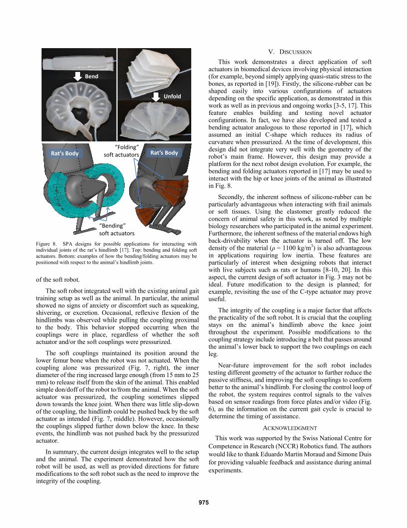
actuators in biomedical devices involving physical interaction (for example, beyond simply applying quasi-static stress to the bones, as reported in [19]). Firstly, the silicone-rubber can be shaped easily into various configurations of actuators depending on the specific application, as demonstrated in this work as well as in previous and ongoing works [3-5, 17]. This feature enables building and testing novel actuator configurations. In fact, we have also developed and tested a bending actuator analogous to those reported in [17], which assumed an initial C-shape which reduces its radius of curvature when pressurized. At the time of development, this design did not integrate very well with the geometry of the robot’s main frame. However, this design may provide a platform for the next robot design evolution. For example, the bending and folding actuators reported in [17] may be used to interact with the hip or knee joints of the animal as illustrated in Fig. 8.
Secondly, the inherent softness of silicone-rubber can be particularly advantageous when interacting with frail animals or soft tissues. Using the elastomer greatly reduced the concern of animal safety in this work, as noted by multiple biology researchers who participated in the animal experiment. Furthermore, the inherent softness of the material endows high back-drivability when the actuator is turned off. The low density of the material (ρ = 1100 kg/m3) is also advantageous in applications requiring low inertia. These features are particularly of interest when designing robots that interact with live subjects such as rats or humans [8-10, 20]. In this aspect, the current design of soft actuator in Fig. 3 may not be ideal. Future modification to the design is planned; for example, revisiting the use of the C-type actuator may prove useful.
The integrity of the coupling is a major factor that affects the practicality of the soft robot. It is crucial that the coupling stays on the animal’s hindlimb above the knee joint throughout the experiment. Possible modifications to the coupling strategy include introducing a belt that passes around the animal’s lower back to support the two couplings on each leg.
Near-future improvement for the soft robot includes testing different geometry of the actuator to further reduce the passive stiffness, and improving the soft couplings to conform better to the animal’s hindlimb. For closing the control loop of the robot, the system requires control signals to the valves based on sensor readings from force plates and/or video (Fig. 6), as the information on the current gait cycle is crucial to determine the timing of assistance.
ACKNOWLEDGMENT This work was supported by the Swiss National Centre for
Competence in Research (NCCR) Robotics fund. The authors would like to thank Eduardo Martin Moraud and Simone Duis for providing valuable feedback and assistance during animal experiments.
Figure 8. SPA designs for possible applications for interacting with individual joints of the rat’s hindlimb [17]. Top: bending and folding soft actuators. Bottom: examples of how the bending/folding actuators may be positioned with respect to the animal’s hindlimb joints.
Bend
Unfold
Rat’s Body Rat’s Body“Folding”
soft actuators
“Bending” soft actuators
975

REFERENCES [1] Y.-L. Park, C. Majidi, R. Kramer, P. Bérard, and R. J. Wood,
"Hyperelastic pressure sensing with a liquid-embedded elastomer," Journal of Micromechanics and Microengineering, vol. 20, p. 125029, 2010.
[2] C. Majidi, R. Kramer, and R. Wood, "A non-differential elastomer curvature sensor for softer-than-skin electronics," Smart Materials and Structures, vol. 20, p. 105017, 2011.
[3] F. Ilievski, A. D. Mazzeo, R. F. Shepherd, X. Chen, and G. M. Whitesides, "Soft Robotics for Chemists," Angewandte Chemie, vol. 123, pp. 1930-1935, 2011.
[4] R. V. Martinez, J. L. Branch, C. R. Fish, L. Jin, R. F. Shepherd, R. M. D. Nunes, Z. Suo, and G. M. Whitesides, "Robotic Tentacles with Three-Dimensional Mobility Based on Flexible Elastomers," Advanced Materials, vol. 25, pp. 205-212, 2013.
[5] R. F. Shepherd, F. Ilievski, W. Choi, S. A. Morin, A. A. Stokes, A. D. Mazzeo, X. Chen, M. Wang, and G. M. Whitesides, "Multigait soft robot," Proceedings of the National Academy of Sciences, November 28 2011.
[6] R. F. Shepherd, A. A. Stokes, J. Freake, J. Barber, P. W. Snyder, A. D. Mazzeo, L. Cademartiri, S. A. Morin, and G. M. Whitesides, "Using Explosions to Power a Soft Robot," Angewandte Chemie, vol. 125, pp. 2964-2968, 2013.
[7] J. R. Amend, E. M. Brown, N. Rodenberg, H. M. Jaeger, and H. Lipson, "A Positive Pressure Universal Gripper Based on the Jamming of Granular Material," Robotics, IEEE Transactions on, vol. 28, pp. 341-350, 2012.
[8] Y. S. Song, "Design, Implementation and Validation of an Exoskeletal Robot for Locomotion Studies in Rodents," Massachusetts Institute of Technology, 2012.
[9] N. Dominici, U. Keller, H. Vallery, L. Friedli, R. Van Den Brand, M. L. Starkey, P. Musienko, R. Riener, and G. Courtine, "Versatile robotic interface to evaluate, enable and train locomotion and balance after neuromotor disorders," Nature Medicine, vol. 18, pp. 1142-1147, 2012.
[10] A. Roy, H. I. Krebs, S. L. Patterson, T. N. Judkins, I. Khanna, L. W. Forrester, R. M. Macko, and N. Hogan, "Measurement of Human Ankle Stiffness Using the Anklebot," in IEEE 10th International Conference on Rehabilitation Robotics (ICORR), 2007, pp. 356-363.
[11] A. L. Behrman and S. J. Harkema, "Locomotor Training After Human Spinal Cord Injury: A Series of Case Studies," Physical Therapy, vol. 80, pp. 688-700, July 2000.
[12] G. Courtine, Y. Gerasimenko, R. van den Brand, A. Yew, P. Musienko, H. Zhong, B. Song, Y. Ao, R. M. Ichiyama, and I. Lavrov, "Transformation of nonfunctional spinal circuits into functional states after the loss of brain input," Nature neuroscience, vol. 12, pp. 1333-1342, 2009.
[13] J. Cha, C. Heng, D. J. Reinkensmeyer, R. R. Roy, V. R. Edgerton, and R. D. De Leon, "Locomotor ability in spinal rats is dependent on the amount of activity imposed on the hindlimbs during treadmill training," Journal of neurotrauma, vol. 24, pp. 1000-1012, 2007.
[14] S. F. Giszter, M. R. Davies, and V. Graziani, "Motor strategies used by rats spinalized at birth to maintain stance in response to imposed perturbations," Journal of neurophysiology, vol. 97, pp. 2663-2675, 2007.
[15] R. van den Brand, J. Heutschi, Q. Barraud, J. DiGiovanna, K. Bartholdi, M. Huerlimann, L. Friedli, I. Vollenweider, E. M. Moraud, S. Duis, N. Dominici, S. Micera, P. Musienko, and G. Courtine, "Restoring Voluntary Control of Locomotion after Paralyzing Spinal Cord Injury," Science, vol. 336, pp. 1182-1185, June 1 2012.
[16] C. Heng and R. D. de Leon, "The rodent lumbar spinal cord learns to correct errors in hindlimb coordination caused by viscous force perturbations during stepping," The Journal of neuroscience, vol. 27, pp. 8558-8562, 2007.
[17] Y. Sun, Y. S. Song, and J. Paik, "Characterization of Silicone Rubber Based Soft Pneumatic Actuator," in IEEE/RSJ International Conference on Intelligent Robots and Systems (IROS), Tokyo, Japan, 2013.
[18] U. I. Udoekwere, A. Ramakrishnan, L. Mbi, and S. F. Giszter, "Robot Application of Elastic Fields to the Pelvis of the Spinal Transected Rat: a Tool for Detailed Assessment and Rehabilitation," in 28th Annual International Conference of the IEEE Engineering in Medicine and Biology Society (EMBS), 2006, pp. 3684-3687.
[19] B. Valteau, G. Grimard, I. Londono, F. Moldovan, and I. Villemure, "In vivo dynamic bone growth modulation is less detrimental but as effective as static growth modulation," Bone, vol. 49, pp. 996-1004, 2011.
[20] S. Hussain, S. Q. Xie, and G. Liu, "Robot assisted treadmill training: Mechanisms and training strategies," Medical Engineering & Physics, vol. 33, pp. 527-533, 2011.
976