Embed Size (px)
Citation preview

Abstract— This paper proposes a new method to estimate the
3D motion of a vehicle based on car-like structured motion
model using an omnidirectional camera and a laser
rangefinder. In recent years, motion estimation using vision
sensor has improved by assuming planar motion in most
conventional research to reduce requirement parameters and
computational cost. However, for real applications in
environment of outdoor terrain, the motion does not satisfy this
condition. In contrast, our proposed method uses one
corresponding image point and motion orientation to estimate
the vehicle motion in 3D. In order to reduce requirement
parameters for speedup computational systems, the vehicle
moves under car-like structured motion model assumption. The
system consists of a camera and a laser rangefinder mounted
on the vehicle. The laser rangefinder is used to estimate motion
orientation and absolute translation of the vehicle. An
omnidirectional image-based one-point correspondence is used
for combining with motion orientation and absolute translation
to estimate rotation components of yaw, pitch angles and three
translation components of Tx, Ty, and Tz. Real experiments in
sloping terrain demonstrate the accuracy of vehicle localization
estimation using the proposed method. The error at the end of
travel position of our method, one-point RANSAC are 1.1%,
5.1%, respectively.
Index Terms— 3D motion estimation, fusion multiple
sensors, laser range finder, omnidirectional camera, one-point
correspondence.
I. INTRODUCTION
Motion estimation, path planning and mapping are
important areas of research with various applications in autonomous vehicles, intelligent transport systems, security
and surveillance, process control, remote sensing, robotics,
and aerospace. Despite considerable researches during the
last few years, there are now many investigations to improve
accuracy and reduce computational cost as well as makes
reliability of estimative results in long travelling distances
under different kinds of complex terrain.
In recent years, many methods have been developed for
vehicle navigation, including visual odometry [1], which can
be divided into several categories. The first group of
methods uses only vision systems, e.g., monocular camera, stereo cameras, and catadioptric cameras. The second group
This work was supported by the National Research Foundation of
Korea (NRF) Grant funded by the Korean Government (MOE) (2013R1A1A2009984).
Authors are with School of Electrical Engineering, University of Ulsan,
680-749 Korea (phone: +82-52-259-1664; e-mail: [email protected],
{hvzung, danilo, lemyha}@islab.ulsan.ac.kr).
uses other electromagnetic devices without vision, e.g.,
Global Positioning System (GPS), Inertial Measurement
Unit (IMU), wheel odometers, and laser rangefinder (LRF).
The third method group combines electromagnetic devices
and vision systems.
This paper proposes a new method to integrate the vision and LRF devices for 3D motion and localization estimation during vehicle motion. The nonholonomic system constraints of car-like structure motion, epipolar geometry are used to restrict the motion model, which minimizes the motion parameters, and reduce computational time. The model requires only one-point correspondence and motion orientation, absolute translation for solving problem.
This paper consists of seven sections. Section 2 summarizes related works and proposes the scheme method. Next, section 3 describes the epipolar geometry constraint. The motion model will be analyzed in section 4. In the next step, section 5 presents motion estimation. Section 6 presents the experiments. Finally, conclusions for future work are drawn in section 7.
II. RELATED WORK AND METHOD PROPOSAL
In recent years, in the localization and mapping field, the combination of vision systems and other electromagnetic devices has been considered as a solution for the accumulated error problem. Related works are separated into several categories. In the first group, the early research on vision-based odometry used a single perspective camera [2, 3]. Other authors proposed methods using a binocular camera [4, 5]. Because of field of view limitations, some author groups proposed methods using an omnidirectional camera. Typical omnidirectional vision-based odometry systems are presented in [6-10]. The basic principles of these approaches are feature correspondence and epipolar geometry constraints. The difficult problem of feature matching is most applicable to the high outliers. Therefore, the results often have large errors. The final trajectory is acceptable if the vehicle moves in an indoor environment, over a short distance, or in a special outdoor terrain. The trajectory will diverge comparing with ground truth when the vehicle moves over a large distance or in a complex outdoor terrain. This is also the challenge of incremental methods of visual odometry, simultaneous localization and mapping (SLAM). Moreover, the scale of trajectories is ambiguous if only a monocular vision system is used. In the second group, multiple magnetic sensors are integrated in the system [11-14]. On the other work, [15] proposed the method using rotation multiple 2D laser rangefinders system for constructing maps of large-scale areas with almost planar motion assumption under the fairly flat road. The GPS
3D Motion Estimation Based on Pitch and Azimuth from Respective
Camera and Laser Rangefinder Sensing*
Van-Dung Hoang, Danilo Cáceres Hernández, My-Ha Le, Kang-Hyun Jo, Senior Member, IEEE
2013 IEEE/RSJ International Conference onIntelligent Robots and Systems (IROS)November 3-7, 2013. Tokyo, Japan
978-1-4673-6357-0/13/$31.00 ©2013 IEEE 735

receiver devices are used for global positioning, and IMU or wheel odometers are used for local position estimation. These methods often yield an acceptable result on a large-scale. However, the final trajectories often drift, and GPS is not always correct in an urban scene. This is also the challenge of localization and navigation without vision systems.
Other methods, combining the two groups of methodologies mentioned above, have been considered as a solution to overcome these disadvantages. Some author groups, as in [16-19] have proposed a method using a vision system and other electromagnetic devices. The proposed method combines CCD camera with laser sensors for reconstruction scene and used other kind of sensors for motion estimation in [20]. The results are significantly improved. However, the vehicle motion in most conventional research is assumed planar. This is not always true in the real world. When the vehicle moves along slope road, the trajectory and position is inaccurate.
Based on the above analysis, a method combining an omnidirectional camera and LRF device is proposed. The advantage of the omnidirectional camera is the large field of view, since the 3600 view produces rich information of a surrounding scene. Even when the vehicle rotates with a large angle, landmarks are still tracked. Using information from the LRF device, the absolute trajectories and orientation of motion can be rapidly computed.
The overview of this proposed method for 3D motion estimation is shown in Fig. 1. There are two kinds of information to be determined including translation components [TX, TY, TZ]T and rotation components of pitch
(E), yaw (.), and roll (J). In order to estimate rotation angles, some authors have proposed using feature point-based methods for calculating geometry constraints [3, 4, 7]. Others have proposed using appearance-based methods [8, 21]. Whereas, the paper [13] proposed method for
integrating magnetic devices. In this paper, at the first position of vehicle, the motion orientation is determined. Successive laser scans is used to estimate the absolute translational and motion orientation of the vehicle by using the Iterative Closest Point (ICP) method [22]. Correspondence points are extracted from successive sequence images by using the scale invariant feature transform (SIFT) method [23]. Essential matrixes between consecutive images are computed based on epipolar geometry properties to estimate the vehicle motion. Laser scans and omnidirectional images are simultaneously collected as synchronized for processing.
III. CAMERA POSES CONSTRAINT
The visual odometry system is composed of consecutive image pair constraints. Those constraints are analyzed directly from the epipolar constraint using the essential matrix. Fig. 2 shows a 3D point P with respect to two correspondence reprojection rays of r and r' from the focal point of the hyperboloid mirror to P. The rays of r and r’ are observed from two camera poses, whose relative constraint can be described as follows:
0' Err T (1)
where the essential matrix E is defined as E=[T]uR. The
matrix [T]u is a skewed symmetric matrix of translation vector T=[TX,TY,TZ]T. Rotation matrix R=RYRZRX, where RY,
RZ, RX are pitch E , yaw D, and roll J rotation matrix, respectively.
> @0
0
0
Z Y
Z X
Y X
T T
T T T
T Tu
�ª º« » �« »« »�¬ ¼
(2)
The attention should be paid about the joint rotation matrix. The multiplication of matrix according to X, Y, Z is not commutative in algebra. The designer also can impose these orders, for example, Z-Y-X, Y-Z-X, X-Y-Z… Here, the Y-Z-X system is select because of its convention using in this experiments system setup. Three rotational and three translational components of the camera in sequential camera positions can be estimated by solving (1). Several methods
Fig. 1. The method proposed for vehicle motion estimation
Fig.2. Epipolar geometry
(3)
736
have been applied to solve this problem. Among them, the eight-point [24], five-point algorithms [2] were represented and is applied to the perspective camera. Recently, one-point RANSAC [7] has been considered as a typical algorithm to reduce the number of point correspondence using the car-like structure motion model. The limitations of this method are planar motion assumption and ambiguity translation due to the constant velocity assumption. This hypothesis is not always true in reality. This paper solves 3D motion problem using one-point image correspondence from camera, and motion orientation, translation from laser rangefinder.
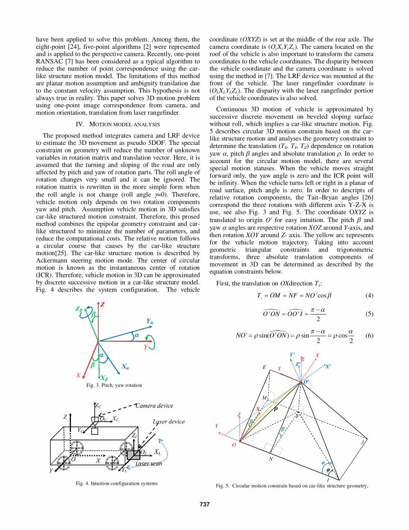
IV. MOTION MODEL ANALYSIS
The proposed method integrates camera and LRF device to estimate the 3D movement as pseudo 5DOF. The special constraint on geometry will reduce the number of unknown variables in rotation matrix and translation vector. Here, it is assumed that the turning and sloping of the road are only affected by pitch and yaw of rotation parts. The roll angle of rotation changes very small and it can be ignored. The rotation matrix is rewritten in the more simple form when
the roll angle is not change (roll angle J=0). Therefore, vehicle motion only depends on two rotation components yaw and pitch. Assumption vehicle motion in 3D satisfies car-like structured motion constraint. Therefore, this prosed method combines the epipolar geometry constraint and car-like structured to minimize the number of parameters, and reduce the computational costs. The relative motion follows a circular course that causes by the car-like structure motion[25]. The car-like structure motion is described by Ackermann steering motion mode. The center of circular motion is known as the instantaneous center of rotation (ICR). Therefore, vehicle motion in 3D can be approximated by discrete successive motion in a car-like structure model. Fig. 4 describes the system configuration. The vehicle
coordinate (OXYZ) is set at the middle of the rear axle. The camera coordinate is (OcXcYcZc). The camera located on the roof of the vehicle is also important to transform the camera coordinates to the vehicle coordinates. The disparity between the vehicle coordinate and the camera coordinate is solved using the method in [7]. The LRF device was mounted at the front of the vehicle. The laser rangefinder coordinate is (OLXLYLZL). The disparity with the laser rangefinder portion of the vehicle coordinates is also solved.
Continuous 3D motion of vehicle is approximated by successive discrete movement on beveled sloping surface without roll, which implies a car-like structure motion. Fig. 5 describes circular 3D motion constrain based on the car-like structure motion and analyses the geometry constraint to determine the translation (TX, TY, TZ) dependence on rotation
yaw D, pitch E angles and absolute translation U. In order to account for the circular motion model, there are several special motion statuses. When the vehicle moves straight forward only, the yaw angle is zero and the ICR point will be infinity. When the vehicle turns left or right in a planar of road surface, pitch angle is zero. In order to descripts of relative rotation components, the Tait–Bryan angles [26] correspond the three rotations with different axis Y-Z-X is use, see also Fig. 3 and Fig. 5. The coordinate OXYZ is
translated to origin O' for easy intuition. The pitch E and
yaw D angles are respective rotation XOZ around Y-axis, and then rotation XOY around Z- axis. The yellow arc represents for the vehicle motion trajectory. Taking into account geometric triangular constraints and trigonometric transforms, three absolute translation components of movement in 3D can be determined as described by the equation constraints below.
First, the translation on OXdirection Tx:
'cos
xT OM NF NO E
(4)
n n' '2
O ON OO IS D�
(5)
n' sin( ' ) sin cos
2 2NO O ON
S D DU U U
�
(6)
Fig. 4. Intuition configuration systems
Fig. 3. Pitch, yaw rotation
Fig. 5. Circular motion constrain based on car-like structure geometry,
737

Substituting (6) into (4), the result is
cos cos
2x
TD
U E (7)
Second, translation on OY direction:
cos sin
2 2y
T ONS D D
U U�
(8)
Third, translation on OZ direction:
' 'sin
zT FO NO E (9)
The result is substitution (6) into (9)
' cos sin
2z
T FOD
U E
(10)
V. MOTION ESTIMATION
The motion estimation is equivalent five components-transformation solution, with roll angle is ignored. To find the solution, substituting TX, TY, TZ into translation
expression give the result (11), J=0 is substituted into (3) giving the result (12).
cos( / 2) cos
sin( / 2)
cos( / 2) sin
X
Y
Z
T
T T
T
D E
U D
D E
ª º ª º« » « » « » « »« » « »¬ ¼¬ ¼
(11)
cos cos sin cos sin
sin cos 0
-cos sin sin sin cos
Y ZR R R
D E D E E
D D
D E D E E
�ª º« » « »« »¬ ¼
(12)
The expression essential matrix E=[T]xR is substituted into (1) to solve the problem. Now, equation (1) is only
dependent on three unknown variables of E, D, U. As
mentioned above, D and U are estimated using LRF information. Therefore, the final solution requires one corresponding image point. In addition, the problem can be also solved by two corresponding image points without LRF in scale motion.
A. Computing rotation angle and absolute translation U
The LRF measures distances from the laser device center to scan points on landmarks. Two laser scans are collected from two successive device positions. They provide the distance capture on the horizontal cross-section of the same world landmarks. The solution of the laser scans matching problem implies rigid-body transformation of the device, which is represented by rotation and translation. The ICP algorithm [22] is used for laser scans matching to estimate rotation angle and absolution translation. They are
approximated for yaw angle D as directional motion and
module translation U of vehicle motion. This work assumes the transformation of the LRF with respect to camera transformation.
B. Computing E angle
Since D angle and module U are known, the corresponding rays of r and r' from the two image sequence are require to
solve (1) computing E angle. To solve this problem,
corresponding points between images in the omnidirectional successive sequence image are extracted by the SIFT method [23]. Then the method in [27] is used to construct the reflection ray from the center of the mirror to a point in 3D space, see also Fig. 2. The refection ray r is computed based on the image point.
r=[su, sv, sf-2c]T where
2 2 22
2 2 2 2 2( )
fc b u v fs a
a f b u v
� � �
� � (13)
(u, v) is the image coordinate, a and b are parameters of the
mirror, c2=a2+b
2, and f is the focal length of the camera. The
parameters a, b and f are computed based on intrinsic camera information that is extracted by the toolbox for calibration
omnidirectional camera [28].
Now, one variable E is determined using one correspondence image point. To deal with outliers, RANSAC has been established as the standard method for outlier removal. The histogram method [7] has also been considered for this paper. In RANSAC theoretical, it is unnecessary to try all possible samples to find the best corresponding points to estimate the relative transformation. The iterative number of RANSAC depends on the number of corresponding points [24], which are required to estimate vehicle motion. The number of iterations is computed by following
log(1 )
log(1 (1 ) )n
pk
w
�
� � (14)
where w is percentage of choosing inliers in data points of
any selection that is the quotient of inliers number and all
corresponding points. Therefore, (1-w)n is the probability for
n all points are inliers. The probability p to insure at least
one random selected corresponding point is successful,
which does not include an outlier. For example, an inliers
ratio w=0.5 and a success solution probability p=0.99, the
number of iteration of eight-point, five-point, and one-point RANSAC are 1177, 147 and 7, respectively. Therefore, it is
extremely importance to minimize parameters for motion
estimation to reduce computational cost of outliers filter.
VI. EXPERIMENTS
In this section, experiments are presented to describe the effectiveness of the proposed method. Images and laser measurements are acquired by a hyperbolic omnidirectional camera and LRF device mounted on a vehicle as shown in Fig. 6. The experiments also compare with the global motion trajectory and final error of this method and the one-point RANSAC method proposed by [7]. In order to estimate the motion in absolute distance (definite measurement unit), the absolute translation from LRF is also used in one-point method. Both methods also assume the motion under car-like structure motion model. The vehicle moved in the campus with large slope terrain. The maximum slope of the road is about 30 degree, the maximum of road curvature is about 100 degrees, and the disparate elevation is about 3.4 meters. The travel distance is 645 meters, which consists of 929 frame images and laser scans. The maximum speed is 20 km/h. It is not necessary to maintain a constant speed. The
738

road on Google map is considered as the ground truth trajectory for comparison.
Fig. 7 (a) plots the top view of estimative result on aerial image from Google map. The ground truth is indicated by a dashed yellow line. The blue, green, and red curves are
motion trajectories based on the proposed method, the one-point method, and the GPS receiver, respectively. The one-point RANSAC method estimates the motion under flat surface of the road assumption. Therefore, a large error result when the vehicle moves on a large sloping road, see also Fig. 7 (b, c), and Table I.
Table I shows comparing the errors given by our proposed method as well one-point RANSAC and GPS data. The criteria for comparison are the starting position based on Google map and an average of GPS measures. The start position is located at (35.544427o, 129.256436o, 69.8m), and the end travel is located at (35.544232o, 129.256438o, 68.5m). Information at the start location is used for all methods.
Fig. 8 shows the changes of yaw, pitch angle over successive frames. The yaw angle depends on the steering wheel. The large pitch angle at several positions depends on large slope of road surface. Experimental results also indicate that GPS has not accumulative global error. However, the partial error is quite large. In contrast, the vision and laser rangefinder can deal with partial errors. However, the method is also contracted with the traditional problem that is accumulated global error. The error at the end of travel from GPS receiver, proposed method, and one-point RANSAC are 0.7%, 1.1%, and 5.1%, respectively.
Fig. 9 presents trajectory of about 3,982 meters distance of travel. In this experiment, vehicle moved in long distance under difference terrain condition. Therefore, the LRF
Fig. 6. Vehicle equipped with multiple devices
(a)
(b)
(c)
Fig. 7. Plot trajectory comparing results: (a) top view on Google map, (b) side view and real scenes, (c) 3D view.
Fig. 9. Travelling localization estimation in long-distance
Fig. 8. Plot the value of yaw, pitch, roll rotation angle
739
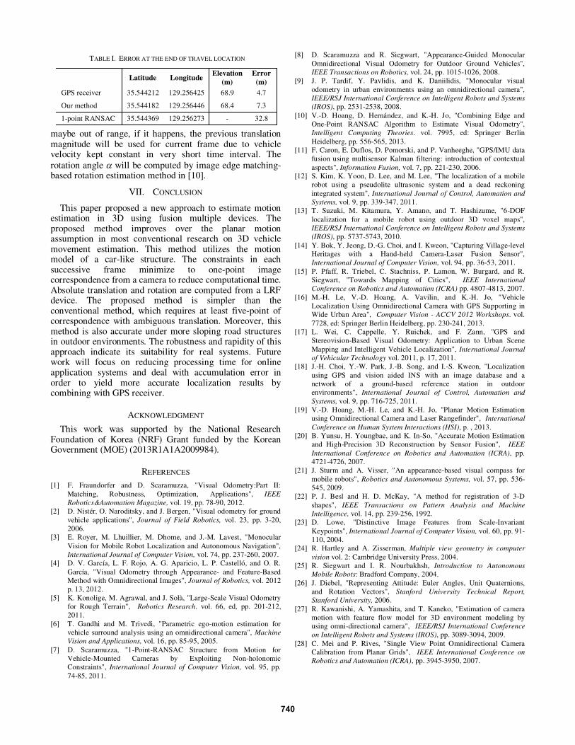
maybe out of range, if it happens, the previous translation magnitude will be used for current frame due to vehicle velocity kept constant in very short time interval. The
rotation angle D will be computed by image edge matching- based rotation estimation method in [10].
VII. CONCLUSION
This paper proposed a new approach to estimate motion estimation in 3D using fusion multiple devices. The proposed method improves over the planar motion assumption in most conventional research on 3D vehicle movement estimation. This method utilizes the motion model of a car-like structure. The constraints in each successive frame minimize to one-point image correspondence from a camera to reduce computational time. Absolute translation and rotation are computed from a LRF device. The proposed method is simpler than the conventional method, which requires at least five-point of correspondence with ambiguous translation. Moreover, this method is also accurate under more sloping road structures in outdoor environments. The robustness and rapidity of this approach indicate its suitability for real systems. Future work will focus on reducing processing time for online application systems and deal with accumulation error in order to yield more accurate localization results by combining with GPS receiver.
ACKNOWLEDGMENT
This work was supported by the National Research Foundation of Korea (NRF) Grant funded by the Korean Government (MOE) (2013R1A1A2009984).
REFERENCES
[1] F. Fraundorfer and D. Scaramuzza, "Visual Odometry:Part II:
Matching, Robustness, Optimization, Applications", IEEE
Robotics&Automation Magazine, vol. 19, pp. 78-90, 2012.
[2] D. Nistér, O. Naroditsky, and J. Bergen, "Visual odometry for ground
vehicle applications", Journal of Field Robotics, vol. 23, pp. 3-20,
2006.
[3] E. Royer, M. Lhuillier, M. Dhome, and J.-M. Lavest, "Monocular
Vision for Mobile Robot Localization and Autonomous Navigation",
International Journal of Computer Vision, vol. 74, pp. 237-260, 2007.
[4] D. V. García, L. F. Rojo, A. G. Aparicio, L. P. Castelló, and O. R.
García, "Visual Odometry through Appearance- and Feature-Based
Method with Omnidirectional Images", Journal of Robotics, vol. 2012
p. 13, 2012.
[5] K. Konolige, M. Agrawal, and J. Solà, "Large-Scale Visual Odometry
for Rough Terrain", Robotics Research. vol. 66, ed, pp. 201-212,
2011.
[6] T. Gandhi and M. Trivedi, "Parametric ego-motion estimation for
vehicle surround analysis using an omnidirectional camera", Machine
Vision and Applications, vol. 16, pp. 85-95, 2005.
[7] D. Scaramuzza, "1-Point-RANSAC Structure from Motion for
Vehicle-Mounted Cameras by Exploiting Non-holonomic
Constraints", International Journal of Computer Vision, vol. 95, pp.
74-85, 2011.
[8] D. Scaramuzza and R. Siegwart, "Appearance-Guided Monocular
Omnidirectional Visual Odometry for Outdoor Ground Vehicles",
IEEE Transactions on Robotics, vol. 24, pp. 1015-1026, 2008.
[9] J. P. Tardif, Y. Pavlidis, and K. Daniilidis, "Monocular visual
odometry in urban environments using an omnidirectional camera",
IEEE/RSJ International Conference on Intelligent Robots and Systems
(IROS), pp. 2531-2538, 2008.
[10] V.-D. Hoang, D. Hernández, and K.-H. Jo, "Combining Edge and
One-Point RANSAC Algorithm to Estimate Visual Odometry",
Intelligent Computing Theories. vol. 7995, ed: Springer Berlin
Heidelberg, pp. 556-565, 2013.
[11] F. Caron, E. Duflos, D. Pomorski, and P. Vanheeghe, "GPS/IMU data
fusion using multisensor Kalman filtering: introduction of contextual
aspects", Information Fusion, vol. 7, pp. 221-230, 2006.
[12] S. Kim, K. Yoon, D. Lee, and M. Lee, "The localization of a mobile
robot using a pseudolite ultrasonic system and a dead reckoning
integrated system", International Journal of Control, Automation and
Systems, vol. 9, pp. 339-347, 2011.
[13] T. Suzuki, M. Kitamura, Y. Amano, and T. Hashizume, "6-DOF
localization for a mobile robot using outdoor 3D voxel maps",
IEEE/RSJ International Conference on Intelligent Robots and Systems
(IROS), pp. 5737-5743, 2010.
[14] Y. Bok, Y. Jeong, D.-G. Choi, and I. Kweon, "Capturing Village-level
Heritages with a Hand-held Camera-Laser Fusion Sensor",
International Journal of Computer Vision, vol. 94, pp. 36-53, 2011.
[15] P. Pfaff, R. Triebel, C. Stachniss, P. Lamon, W. Burgard, and R.
Siegwart, "Towards Mapping of Cities", IEEE International
Conference on Robotics and Automation (ICRA) pp. 4807-4813, 2007.
[16] M.-H. Le, V.-D. Hoang, A. Vavilin, and K.-H. Jo, "Vehicle
Localization Using Omnidirectional Camera with GPS Supporting in
Wide Urban Area", Computer Vision - ACCV 2012 Workshops. vol.
7728, ed: Springer Berlin Heidelberg, pp. 230-241, 2013.
[17] L. Wei, C. Cappelle, Y. Ruichek, and F. Zann, "GPS and
Stereovision-Based Visual Odometry: Application to Urban Scene
Mapping and Intelligent Vehicle Localization", International Journal
of Vehicular Technology vol. 2011, p. 17, 2011.
[18] J.-H. Choi, Y.-W. Park, J.-B. Song, and I.-S. Kweon, "Localization
using GPS and vision aided INS with an image database and a
network of a ground-based reference station in outdoor
environments", International Journal of Control, Automation and
Systems, vol. 9, pp. 716-725, 2011.
[19] V.-D. Hoang, M.-H. Le, and K.-H. Jo, "Planar Motion Estimation
using Omnidirectional Camera and Laser Rangefinder", International
Conference on Human System Interactions (HSI), p. , 2013.
[20] B. Yunsu, H. Youngbae, and K. In-So, "Accurate Motion Estimation
and High-Precision 3D Reconstruction by Sensor Fusion", IEEE
International Conference on Robotics and Automation (ICRA), pp.
4721-4726, 2007.
[21] J. Sturm and A. Visser, "An appearance-based visual compass for
mobile robots", Robotics and Autonomous Systems, vol. 57, pp. 536-
545, 2009.
[22] P. J. Besl and H. D. McKay, "A method for registration of 3-D
shapes", IEEE Transactions on Pattern Analysis and Machine
Intelligence, vol. 14, pp. 239-256, 1992.
[23] D. Lowe, "Distinctive Image Features from Scale-Invariant
Keypoints", International Journal of Computer Vision, vol. 60, pp. 91-
110, 2004.
[24] R. Hartley and A. Zisserman, Multiple view geometry in computer
vision vol. 2: Cambridge University Press, 2004.
[25] R. Siegwart and I. R. Nourbakhsh, Introduction to Autonomous
Mobile Robots: Bradford Company, 2004.
[26] J. Diebel, "Representing Attitude: Euler Angles, Unit Quaternions,
and Rotation Vectors", Stanford University Technical Report,
Stanford University, 2006.
[27] R. Kawanishi, A. Yamashita, and T. Kaneko, "Estimation of camera
motion with feature flow model for 3D environment modeling by
using omni-directional camera", IEEE/RSJ International Conference
on Intelligent Robots and Systems (IROS), pp. 3089-3094, 2009.
[28] C. Mei and P. Rives, "Single View Point Omnidirectional Camera
Calibration from Planar Grids", IEEE International Conference on
Robotics and Automation (ICRA), pp. 3945-3950, 2007.
TABLE I. ERROR AT THE END OF TRAVEL LOCATION
Latitude Longitude Elevation
(m)
Error
(m)
GPS receiver 35.544212 129.256425 68.9 4.7
Our method 35.544182 129.256446 68.4 7.3
1-point RANSAC 35.544369 129.256273 - 32.8
740