Embed Size (px)
Citation preview

Akseli Kelloniemi
Social Devices Client for Arduino
Master of Science Thesis
Examiner: Prof. Tommi Mikkonen
Subject approved by Faculty of Compu-
ting and Electrical on Council meeting
on 5th of May 2014
I
TIIVISTELMÄ
TAMPEREEN TEKNILLINEN YLIOPISTO
Signaalinkäsittelyn ja tietoliikennetekniikan koulutusohjelma
AKSELI KELLONIEMI: Social Devices Client for Arduino
Diplomityö, 46 sivua
Joulukuu 2014
Pääaine: Sulautetut järjestelmät
Tarkastajat: Prof. Tommi Mikkonen, DI Niko Mäkitalo, TkT Timo Aaltonen
Avainsanat: Social Devices, Arduino, Social Devices Platform, OrchestratorJS
Viime vuosikymmeninä älylaitteiden kehitys on edennyt suurin harppauksin. Samal-
la Internetin mahdollistamat sosiaaliset palvelut, kuten Facebook tai Twitter, ovat
tulleet osaksi arkipäiväistä elämäämme. Tämän diplomityön kirjallisuuskatsaukses-
sa on esitelty Social Devices -konsepti, joka vie sosiaalisten palvelujen ideaa vielä
pidemmälle: konsepti ehdottaa uutta lähestysmistapaa, jossa älylaitteet ja ihmiset
keskenään muodostavat uudenlaisen sosiodigitaalisen järjestelmän. Tässä järjestel-
mässä laitteiden on tarkoitus osallistua ennakoivasti sosiaalisiin tilanteisiin rikas-
tuttamalla niitä jollakin tavalla. Konseptin mukaan laitteet pystyisivät esimerkiksi
osallistumaan keskusteluun tai tuottamaan sellaisia palveluita, jotka rohkaisevat so-
siaaliseen kanssakäymiseen.
Tämän diplomityön tarkoituksena on tutkia onko resurssivajavaisen sulautetun jär-
jestelmän, kuten Arduinon, mahdollista toimia osana Social Devices -järjestelmää.
Jotta laite voi toimia osana Social Devices -konseptia, sen äytyy omata asiakasoh-
jelma, jollainen tässä työssä on yritetty myös toteuttaa. Tämän lisäksi kirjallisuus-
katsauksessa on tarkoitus tutustua Social Devices -käsitteeseen tarkemmin.
Kirjallisuuskatsauksessa läpikävimme Social Devices -konseptin vaatimuksia sekä
ominaisuuksia. Lisäksi esittelimme konseptille kaksi eri toteutusta, Social Devices
Platformin sekä OrchestratorJS:n. Tutustuimme myös näiden arkkitehtuureihin ja
komponentteihin. Ohessa esittelimme myös aihetta sivuavia kommunikaatioproto-
kollia sekä alustan, jolle toteutettu asiakasohjelma on tehty.
Toteutusosuudessa toteutimme asiakasohjelman Arduinolle sekä käsittelimme asia-
kasohjelman suunnitteluun liittyviä asioita sekä niihin vaikuttaneita haasteita. Li-
säksi esittelimme ohjelman muodostaneet komponentit ja lopuksi kokeilimme asia-
kasohjelman toimivuutta Sovial Devices -rajapintaohjelmalla.
Totesimme, että toteutettu asiakasohjelma kykenee toimimaan osana Social Devices
-järjestelmää. Se täyttää sille asetetut vaatimukset, kuten itsensä rekisteröinnin pal-
II
velimelle sekä kommunikoinnin palvelimen kanssa. Lisäksi se osaa päivittää tilansa
ja lähettää RSSI-arvoja lähellä olevista laitteista palvelimelle. Tunnustimme myös,
että on tilanteita, jolloin laite ei kykene vastaamaan palvelinkutsuihin luotettavasti.
Suorituskyvyltään asiakasohjelma täyttää tiettyjen ohjelmien vaatimukset, mutta
tiukkoihin reaaliaikavaatimuksiin se ei pysty vastaamaan.

III
ABSTRACT
TAMPERE UNIVERSITY OF TECHNOLOGY
Master's Degree Programme in Signal Processing and Communications
AKSELI KELLONIEMI : Social Devices Client for Arduino
Master of Science Thesis, 46 pages
December 2014
Major: Embedded Systems
Examiners: Prof. Tommi Mikkonen, M.Sc. Niko Mäkitalo, D.Sc. Timo Aaltonen
Keywords: Social Devices, Arduino, Social Devices Platform, OrchestratorJS
In the last few decades we have been witnessing great technology advancements re-
garding smart devices. At the same time we have accepted few social web services,
such as Facebook or Twitter, to become a part of our everyday lives. Social De-
vices takes a step further regarding social services and proposes a new approach
where people and devices would form together a new socio-digital system. In this
system devices could participate proactively in social situations by enriching them
somehow. According to the concept, the devices could, for instance, participate in a
conversation or enable certain services that would encourage socialising.
This thesis' research question is to �nd out if a modest embedded system, such as
Arduino, is capable of functioning as a Social Device. For a device to function as
a part Social Devices, it needs to have a client software that is tried to be imple-
mented in this thesis. In addition, the Social Devices concept is introduced in the
literature review part.
In the literature review part we discussed about requirements and characteristics of
Social Devices. Additionally, we presented two implementations, the Social Devices
Platform and OrchestratorJS, and introduced their architecture and components.
Furthermore, relating communication protocols and the target platform were pre-
sented.
In the implementation part, we designed a client software that is compatible with the
two implementations of the Social Devices. Additionally, general design paradigms
and matters that in�uenced the design were introduced. Furthermore, the architec-
ture and the components that the client consists of were presented as well. Final-
ly, an example of Social Devices application that demonstrates the client was shown.
We concluded that the implemented client functions as a proof of concept for Social
Devices. The client ful�ls the requirements as it is capable of registering itself to
the server and communicating with it. In addition, the client is able to update its
IV
state values and informing RSSI values of nearby devices to the server. However,
we acknowledged that there are speci�c circumstances where the client can not
respond reliably. Performance-wise we stated that the client is fast enough for certain
applications but can not meet the requirements of an application that needs real-
time responsiveness.
V
PREFACE
This thesis has been made possible by the Tampere University of Technology and
its department of Pervasive Computing. The thesis was funded by Tekes as a part
of Cloud program.
I would like to express my gratitude towards my supervisor, Prof. Tommi Mikkonen
and M.Sc. Niko Mäkitalo who have guided me through the writing process and gi-
ven me excellent advice.
Most of all, I would also like to thank my girlfriend Niina, mother Anne and father
Arto for their continuous and endless support throughout the years.
Tampere, December 3, 2014.

VI
SISÄLTÖ
1. Introduction . . . . . . . . . . . . . . . . . . . . . . . . . . . . . . . . . . . 1
2. Social Devices . . . . . . . . . . . . . . . . . . . . . . . . . . . . . . . . . . 3
2.1 Social Devices concept overview . . . . . . . . . . . . . . . . . . . . . 3
2.2 Action-Oriented Programming . . . . . . . . . . . . . . . . . . . . . . 4
2.3 Requirements and Characteristics . . . . . . . . . . . . . . . . . . . . 6
2.4 Social Devices Platform . . . . . . . . . . . . . . . . . . . . . . . . . 8
2.4.1 Architecture . . . . . . . . . . . . . . . . . . . . . . . . . . . . . 8
2.4.2 Social Devices Platform Client . . . . . . . . . . . . . . . . . . . 9
2.4.3 Controller Component . . . . . . . . . . . . . . . . . . . . . . . . 11
2.4.4 Con�gurator Component . . . . . . . . . . . . . . . . . . . . . . 12
2.4.5 Orchestrator Component . . . . . . . . . . . . . . . . . . . . . . 13
2.5 Orchestrator.js . . . . . . . . . . . . . . . . . . . . . . . . . . . . . . 14
2.6 Related Work . . . . . . . . . . . . . . . . . . . . . . . . . . . . . . . 16
3. Communication Protocols in the Social Devices Platform . . . . . . . . . . 17
3.1 Transmission Control Protocol . . . . . . . . . . . . . . . . . . . . . . 18
3.2 Hypertext Transfer Protocol . . . . . . . . . . . . . . . . . . . . . . . 18
3.3 Websocket . . . . . . . . . . . . . . . . . . . . . . . . . . . . . . . . . 18
3.4 Socket.IO protocol . . . . . . . . . . . . . . . . . . . . . . . . . . . . 19
3.5 Implementation of the SDP Communication Protocol . . . . . . . . . 19
4. Arduino platform . . . . . . . . . . . . . . . . . . . . . . . . . . . . . . . . 22
4.1 Motivation . . . . . . . . . . . . . . . . . . . . . . . . . . . . . . . . . 22
4.2 Arduino Mega . . . . . . . . . . . . . . . . . . . . . . . . . . . . . . . 23
4.3 WiFi Shield . . . . . . . . . . . . . . . . . . . . . . . . . . . . . . . . 24
4.4 Bluetooth Module . . . . . . . . . . . . . . . . . . . . . . . . . . . . . 25
5. Social Devices client for Arduino . . . . . . . . . . . . . . . . . . . . . . . 27
5.1 General design paradigms . . . . . . . . . . . . . . . . . . . . . . . . 27
5.2 Client architecture and implementation . . . . . . . . . . . . . . . . . 29
5.2.1 Client class . . . . . . . . . . . . . . . . . . . . . . . . . . . . . . 30
5.2.2 Initializer class . . . . . . . . . . . . . . . . . . . . . . . . . . . . 31
5.2.3 Orchestrator class . . . . . . . . . . . . . . . . . . . . . . . . . . 31
5.2.4 Proximity class . . . . . . . . . . . . . . . . . . . . . . . . . . . . 32
5.2.5 State class . . . . . . . . . . . . . . . . . . . . . . . . . . . . . . 33
5.3 TalkingDevice interface . . . . . . . . . . . . . . . . . . . . . . . . . . 34
5.4 Future work . . . . . . . . . . . . . . . . . . . . . . . . . . . . . . . . 36
5.5 Summary . . . . . . . . . . . . . . . . . . . . . . . . . . . . . . . . . 37
6. Evaluation . . . . . . . . . . . . . . . . . . . . . . . . . . . . . . . . . . . . 39
6.1 Performance . . . . . . . . . . . . . . . . . . . . . . . . . . . . . . . . 39

VII
6.2 Overall evaluation . . . . . . . . . . . . . . . . . . . . . . . . . . . . . 42
7. Conclusion . . . . . . . . . . . . . . . . . . . . . . . . . . . . . . . . . . . . 43
References . . . . . . . . . . . . . . . . . . . . . . . . . . . . . . . . . . . . . . 45

VIII
LIST OF ABBREVIATIONS
AcOP Action-oriented Programming Model
API Application Programming Interface
HTML Hypertext Markup Language
HTTP Hypertext Transfer Protocol
JSON JavaScript Object Notation
OS Operating System
OSI Open Systems Interconnection
REST Representational State Transfer
RSS Really Simple Syndication
RSSI Received Signal Strength Indicator
SD Social Devices
SDP Social Devices Platform
SOA Service-Oriented Architecture
TCP Transmission Control Protocol
UDP User Datagram Protocol
URI Uniform Resource Identi�er
RAM Random Access Memory
SRAM Static Random Access Memory
WLAN Wireless Local Area Network
1
1. INTRODUCTION
In the last few decades we have been witnessing great technology advancements
regarding smart devices. Nowadays, mobile phones or tablets are more powerful
than 1990s supercomputers [1]. The trend of making devices smart does not just
involve mobile phones but other everyday devices as well: televisions, car computers
or even watches are equipped with capable hardware and networking capabilities for
example.
At the same time when devices have gotten smarter, we have accepted web ser-
vices to become a part of our everyday lives: e.g. Facebook, Twitter and Instagram
have hundreds of millions monthly active users. The aforementioned services have
something in common: they thrive from humans' need to socialize. In one way or
another, these web services o�er a way to share experiences and feelings and means
to stay in touch.
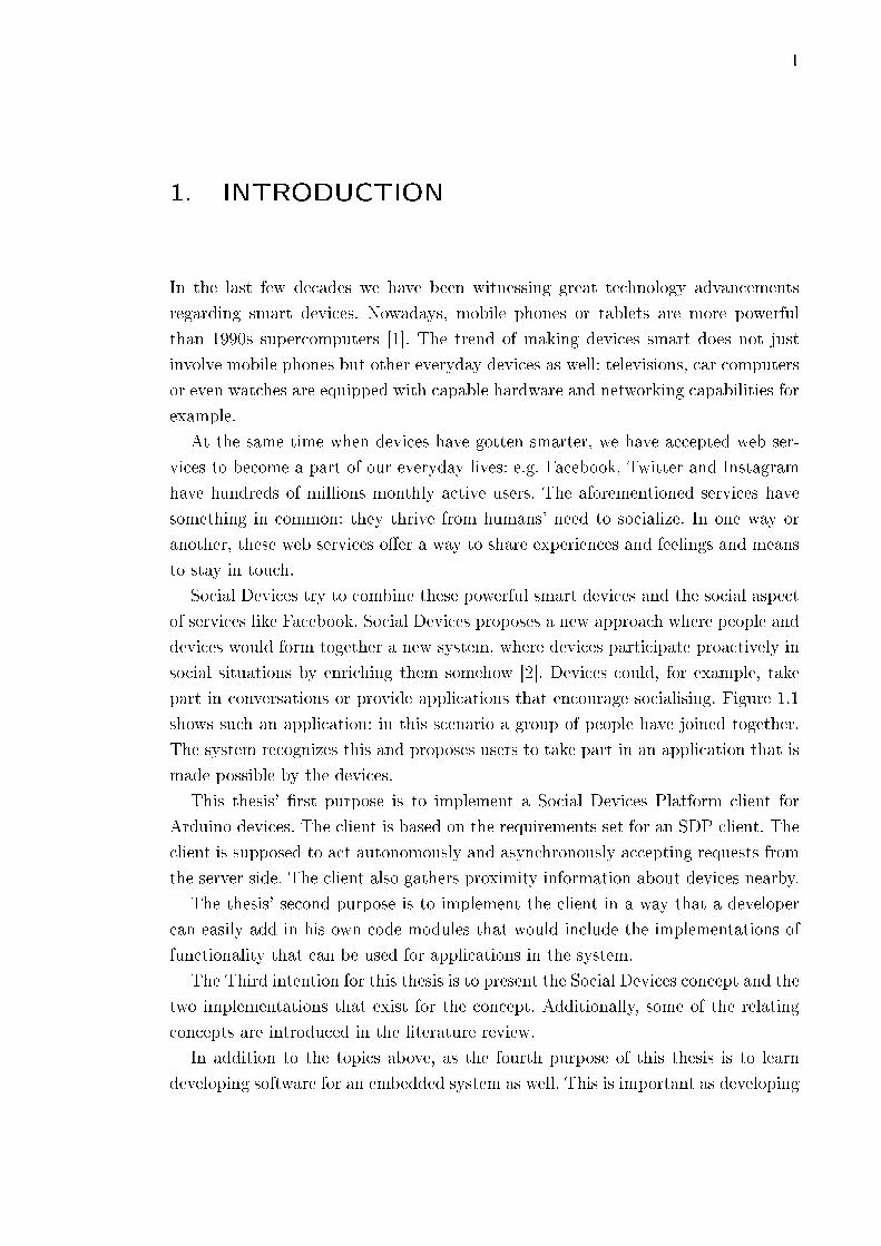
Social Devices try to combine these powerful smart devices and the social aspect
of services like Facebook. Social Devices proposes a new approach where people and
devices would form together a new system, where devices participate proactively in
social situations by enriching them somehow [2]. Devices could, for example, take
part in conversations or provide applications that encourage socialising. Figure 1.1
shows such an application: in this scenario a group of people have joined together.
The system recognizes this and proposes users to take part in an application that is
made possible by the devices.
This thesis' �rst purpose is to implement a Social Devices Platform client for
Arduino devices. The client is based on the requirements set for an SDP client. The
client is supposed to act autonomously and asynchronously accepting requests from
the server side. The client also gathers proximity information about devices nearby.
The thesis' second purpose is to implement the client in a way that a developer
can easily add in his own code modules that would include the implementations of
functionality that can be used for applications in the system.
The Third intention for this thesis is to present the Social Devices concept and the
two implementations that exist for the concept. Additionally, some of the relating
concepts are introduced in the literature review.
In addition to the topics above, as the fourth purpose of this thesis is to learn
developing software for an embedded system as well. This is important as developing

1. Introduction 2
Kuva 1.1: Social Devices use case [2].
software for embedded systems usually involves speci�c problems that usually are
not typical when it comes to regular desktop softwares.
Chapter 2 introduces the Social Devices (SD) concept that is the base idea for
the implementations, the Social Devices Platform (SDP) and OrchestratorJS. The
chapter also elaborates the implementations' architecture and explains the functions
of related components.
In Chapter 3, the communication protocol between the client and the server is
explained more thoroughly. In addition to the actual protocol used in SDP, the
sections in the chapter clarify few underlying protocols as well.
Chapter 4 presents the Arduino platform. First the discussion about why Ar-
duino platform was chosen is rationalized and the latter sections introduce all the
subcomponents needed for the device to function as an SDP client.
The actual implementation is shown in Chapter 5. The chapter consists of sec-
tions where general designs paradigms are presented and sections to introduce the
components that the client consists of. In the latter sections, examples of using the
client and performance evaluation are shown as well.
Chapter 6 presents overall evaluation of the client. In addition, the client is evalua-
ted performance-wise. For instance, response times and discussion how they might
in�uence the user-experience is presented.
Finally, Chapter 7 sums up the thesis by discussing about conclusions.
3
2. SOCIAL DEVICES
In this chapter Social Devices concept is introduced along with two prototype imple-
mentations called Social Devices Platform and Orchestrator.js. Section 2.1 includes
general overview and needs of Social Devices. Section 2.2 elaborates implementa-
tions' underlying programming model and Section 2.3 discusses the needs and cha-
racteristics for the implementations. Implementation and architecture of Social De-
vices Platform are explained in Section 2.4 and Section 2.5 for Orchestrator.js res-
pectively. Related work is presented in Section 2.6. This chapter is based on the
reference [2] unless stated otherwise.
2.1 Social Devices concept overview
Mäkitalo et al. introduce the concept Social Devices in [2]. Social Devices aim at
enriching the interaction between devices or between the user and device by means
of technology. According to the concept, context aware and proactive devices form
together with users a new kind of a socio-digital system. In this system it is possible
for each participant, including devices, start an interaction with devices or people.
In situations where people meet face to face, Social Devices can enrich the inte-
raction and at the same time enrich the interaction between devices. It is possible,
e.g., make the device-to-device interaction explicit to the users.
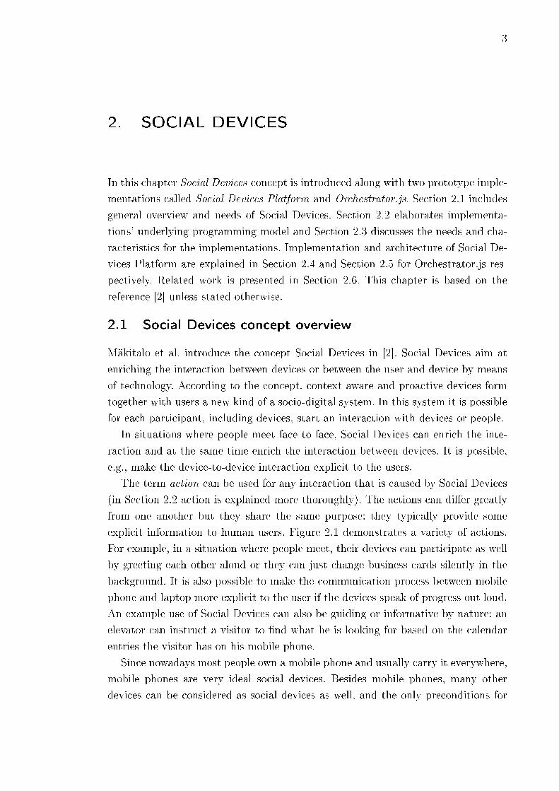
The term action can be used for any interaction that is caused by Social Devices
(in Section 2.2 action is explained more thoroughly). The actions can di�er greatly
from one another but they share the same purpose: they typically provide some
explicit information to human users. Figure 2.1 demonstrates a variety of actions.
For example, in a situation where people meet, their devices can participate as well
by greeting each other aloud or they can just change business cards silently in the
background. It is also possible to make the communication process between mobile
phone and laptop more explicit to the user if the devices speak of progress out loud.
An example use of Social Devices can also be guiding or informative by nature: an
elevator can instruct a visitor to �nd what he is looking for based on the calendar
entries the visitor has on his mobile phone.
Since nowadays most people own a mobile phone and usually carry it everywhere,
mobile phones are very ideal social devices. Besides mobile phones, many other
devices can be considered as social devices as well, and the only preconditions for
2. Social Devices 4
Kuva 2.1: Example uses of Social Devices Platform [2].
Social Devices are computational capability and ability to be aware of and interact
with surrounding devices. This means Social Devices can be very heterogeneous and
include, for example, devices which are highly personal like mobile phones. However,
devices can be impersonal and stationary and possibly located in public places like
an elevator or a screen in a meeting room. Furthermore, heterogeneity is also visible
in devices' di�erent resources, such as speakers, microphones or screens.
Regarding Social Devices, the environment in which actions are executed can be
very dynamic as people do their daily tasks. Sporadic nature of social situations
might lead into a situation where devices, like mobile phones, move in and out of
range of each other so the devices that are able to take part in an action, change
constantly. Considering the devices' state, such as battery level or other modes, are
also notable factor for making the environment more dynamic.
2.2 Action-Oriented Programming
Aaltonen et. al. introduce a paradigm action-oriented programming model (AcOP)
in [3]. The paradigm suggests a new model for programs that involve multiple devices
that function in a cooperative way. The Socials Device Platform and OrchestratorJS
implementations are based on Action-Oriented programming (AcOP) model that
this section discusses in more depth. This section references to [3].
Typically traditional programming languages do not support multi-device pro-
grams by nature. For instance, they do not have the primitives to support synchro-
nized and coordinated activities between multiple devices. Next, the key concepts
that AcOP consists of are introduced.
Devices and Capabilities. In this context multi-device programs consist of
actions as their basic building blocks. Actions, in turn, rely on devices and capabilities
2. Social Devices 5
that the devices o�er. A capability refers to an operation related to a capability that
device is able to perform. It is also expected that the device provides means to use
its capabilities. Additionally, capabilities function as indicators for an ability to
participate in an action: if user has installed a capability on his device, the device
is able to join in an action that utilizes the capability in question.
At the implementation level capabilities are manifested as interfaces. that consist
of operations. In other words, interface is a contract of operations that are related
to a speci�c device and its capability. For instance, later presented (Section 5.3)
TalkingDevice capability's interface contains operation say(). Listing 2.1 shows an
example how interface can be used.
AcOP model does not de�ne which programming language interfaces should be
implemented in. For example, the client presented in this document and its interfaces
are implemented as C++ classes. In practice, communication protocol between the
server and a client abstracts di�erences in programming languages.
Device capabilities or the number of interfaces are not de�ned by the program-
ming model. Since a device can only be invoked through its interfaces, a device with
no capability cannot participate in an action. Furthermore, capabilities are reusable
across di�erent actions and therefore a developer can write new actions without
having to implement device-speci�c programming code.
Actions. An action is the basic unit of modularity, encapsulating the joint beha-
viour of several devices, and de�ning roles, parameters, preconditions, and a body.
Roles are used to determine what roles the participating devices will be a part of.
For instance, in an imaginary action PhotoSharing users can share photos between
each other and roles can be used to de�ne which device shares photos and which
devices can only view the photos.
Parameters include action-speci�c information. In the case of PhotoSharing, pa-
rameter can contain, e.g., �le path or URI to a website where photos are stored. In
TalkingDevice example (Listing 2.1), strings are passed as parameters.
Precondition is a part of an action as well. Precondition de�nes what is expected
from devices that are participating in an action and it must evaluate as boolean
value true. Again when considering PhotoSharing as an action, system could check
if participating devices' owners are Facebook friends for example. TalkingDevice
example on the other hand expects that the devices are near of each other and their
users are friends.
In the body part of an action is de�ned what devices will do during an action
and in which order. Listing 2.1 shows an example of an action body: as a result of
execution of the body two devices will talk to each other.
Triggers and Scheduling. Triggers are AcOP model's manner to initiate ac-
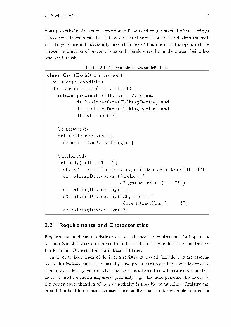
2. Social Devices 6
tions proactively. An action execution will be tried to get started when a trigger
is received. Triggers can be sent by dedicated service or by the devices themsel-
ves. Triggers are not necessarily needed in AcOP but the use of triggers reduces
constant evaluation of preconditions and therefore results in the system being less
resource-intensive.
Listing 2.1: An example of Action de�nition.
class GreetEachOther ( Action )
@act ionprecond i t ion
def pre cond i t i on ( s e l f , d1 , d2 ) :
return proximity ( [ d1 , d2 ] , 2 . 0 ) and
d1 . h a s I n t e r f a c e ( TalkingDevice ) and
d2 . h a s I n t e r f a c e ( TalkingDevice ) and
d1 . i sF r i end ( d2 )
@classmethod
def ge tTr i gg e r s ( c l s ) :
return [ ' GetCloseTr igger ' ]
@actionbody
def body ( s e l f , d1 , d2 ) :
s1 , s2 = smal lTa lkServer . getSentenceAndReply (d1 , d2 )
d1 . t a l k ingDev i c e . say ( "Hel lo , " +
d2 . getOwnerName ( ) + " ! " )
d1 . t a l k ingDev i c e . say ( s1 )
d2 . t a l k ingDev i c e . say ( "Oh, h e l l o " +
d1 . getOwnerName ( ) + " ! " )
d2 . t a l k ingDev i c e . say ( s2 )
2.3 Requirements and Characteristics
Requirements and characteristics are essential since the requirements for implemen-
tation of Social Devices are derived from these. The prototypes for the Social Devices
Platform and OrchestratorJS are described later.
In order to keep track of devices, a registry is needed. The devices are associa-
ted with identities since users usually have preferences regarding their devices and
therefore an identity can tell what the device is allowed to do. Identities can further-
more be used for indicating users' proximity e.g., the more personal the device is,
the better approximation of user's proximity is possible to calculate. Registry can
in addition hold information on users' personality that can for example be used for
2. Social Devices 7
suggesting actions in di�erent contexts.
As precondition for Social Devices suggests, proximity of users and their devices
is needed for social interaction. Proximity is calculated, by each device, with respect
to each device that is supposed to participate in an action. The devices report the
proximity information to the centralized server, which maintains proximity informa-
tion of each device. From the information, the SDP forms a mathematical graph,
where nodes denote devices and edges denote the mutual distance of the devices.
The advantage of such a procedure is that this reduces the required computing on
the devices.
In addition to registering and reporting proximity of other devices, devices have to
inform the server necessary information for action precondition. Action precondition
de�nes what is expected from the participants for the action. Action precondition is
a part of action description along with action body, which de�nes what participant
devices should do during an action. In action preconditions the term interface is used
to characterize the precondition, for example, a device with interface TalkingDevice
has the ability to talk. The owner of a social device can enable and install multiple
interfaces, capabilities, to his liking and by modifying interfaces, user can choose
which privileges SDP can have access to. In case of interface CalendarDevice, user
can give SDP rights to use work calendar in actions with colleagues.
Furthermore, the system needs a mean to determine which devices can and are
willing to participate in an action. This is solved by including information on de-
vices' logical expression in the precondition part of the action description. Interface
itself can function as a logical expression: an action involving a dialog may require
capability to talk; thus participant devices have to implement TalkingDevice inter-
face. Since the environment is usually fairly dynamic, more information is needed
from the devices. For example, a device might be able to talk but in case it is located
in a silent environment it may not be willing to talk. This is handled by monitoring
devices' states. States can vary from boolean-value to any more abstract value which
can indicate, for instance, speci�c state as if device is turned to silent mode or not.
Operations regarding when and if actions are to be executed are decided auto-
matically at runtime. Requests for initiating an action are handled with triggers.
Using of triggers prevents perpetual searching of devices which can be computatio-
nally hard. When certain trigger is received, corresponding action is attempted to
be scheduled. Triggers can also hold update to a state value of a device, an external
event, or change in the proximity group. The decision which action and whether the
action is launched is up to the centralized server that also receives the triggers. This
type of procedure further reduces the computing load of the devices and enables
concentrating functionality to one location.
In addition to scheduling an action, a decision must be made concerning which
2. Social Devices 8
concrete devices are to participate in the action. For example, it may be the case
that after a trigger, there may be several potential actions and several devices that
possibly meet the action preconditions. This leads to a con�guration problem: decide
the action corresponding the trigger, �nd a set of devices and device roles that ful�l
the action preconditions. In practice, problem gets simpli�ed when it is required
that the device, which raised the trigger, �lls a certain role in the action and other
participating devices are in its proximity.
Finally, executing the action requires additional coordination and orchestration
for the devices since they have been designed to run their own software regardless of
other devices. This is solved by using a coordination approach by de�ning a platform
into which coordination is built in. Platform will take care of the control �ow for
the independently operating devices.
The goal of the design approach is to rely on concentrating functionality on the
server side rather than on device autonomy and intelligence. This shows in proximity
management and decision making about actions and device con�gurations that are
not handled by the devices themselves. Hence, rather modest devices can act as
social devices which this thesis arguments about as well.
2.4 Social Devices Platform
Above we introduced the concept of Social Devices and described the characteris-
tics and requirements of Social Devices. This section suggests an answer to these
requirements by showing the architecture and implementation philosophies of Social
Devices Platform. This section is based on the reference [2] unless stated otherwise.
The following subsections �rst introduce the architecture roughly and in the fol-
lowing subsections the necessary components for SDP are presented. The compo-
nents can be categorized as server side components and client component also known
as SDP Client. Server side components include Controller, Orchestrator and Con�-
gurator components.
2.4.1 Architecture
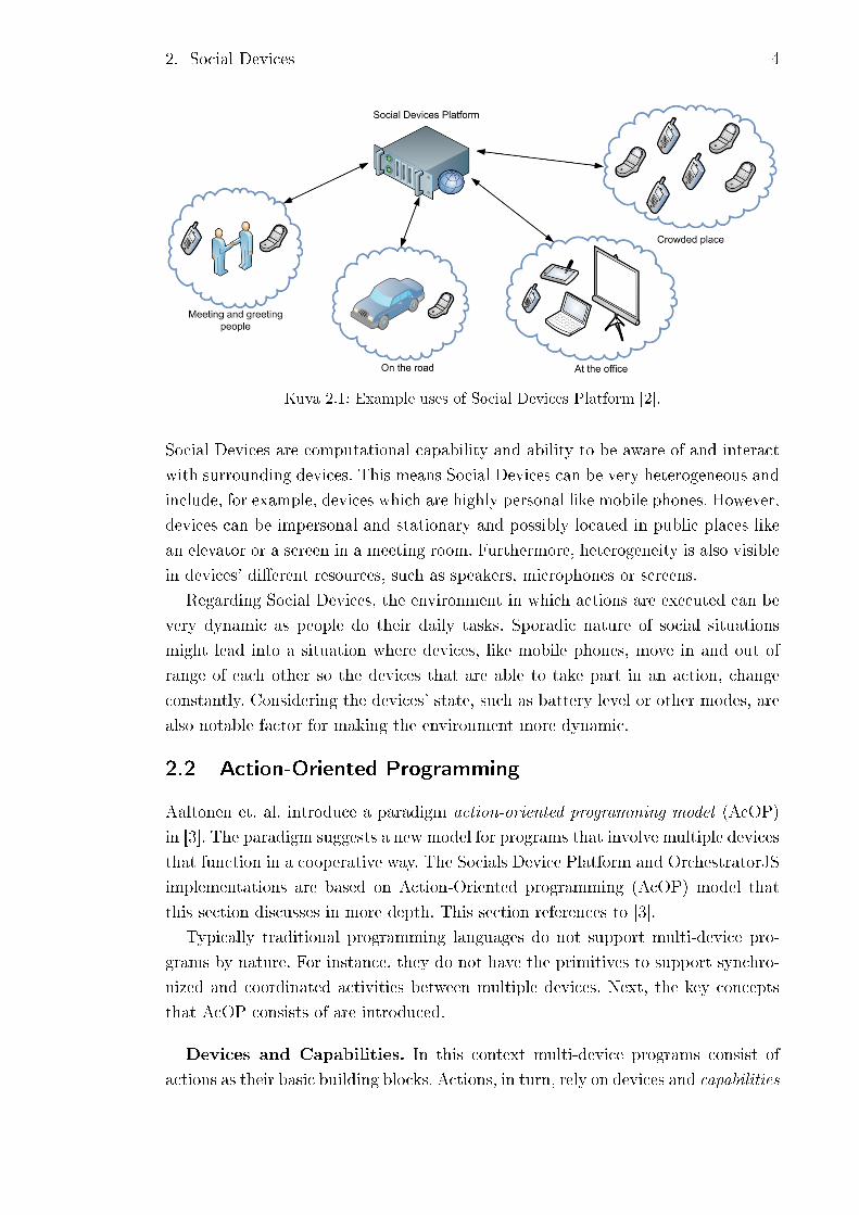
Figure 2.2 illustrates the SDP architecture. Architecture is divided into device side
and server side, which consists of Controller with Proximity subcomponent, as well
as the Con�gurator and the Orchestrator. Client component is a software that is
installed on devices.
Figure 2.2 introduces typical steps required running an action successfully among
devices. Step 1 involves pre-preparations: possible interfaces and actions have to be
de�ned �rst for the Controller and this is done by a developer. Next, users register
their devices and install new capabilities by installing interface implementations

2. Social Devices 9
Kuva 2.2: An overview of the SDP architecture [2].
(Steps 2 and 3). Furthermore, in order to maintain proximity graph and information
about devices' states, devices report their proximities to other devices and state
values (Step 4). Step 5 presents a situation, where a device recognizes a potential
need for an action and raises a trigger. System responds to the trigger by �nding
corresponding action and suitable set of devices for action's preconditions (Steps 6,
7). Finally, if preconditions are met, the execution of the action is started and the
execution is orchestrated among devices (Steps 8 and 9).
2.4.2 Social Devices Platform Client
The SDP Client's main task is to handle device's communication between Controller
and Orchestrator. As Figure 2.2 suggested, �rstly client handles the registration to
the Controller and publishes the installed interfaces. By publishing interfaces the
device indicates that it implements operations regarding the interface. To ensure
that privacy concerns are handled properly, the user can at this point de�ne what
operations are allowed and which preferences are used. After publishing an interface,
2. Social Devices 10
the device can participate in action that requires the respective interface.
The ongoing task of SDP Client is to keep its device's state values up to date and
informing the Controller about the changes. This is important as state values are
part of action precondition that de�nes, for example, which devices can participate
in an action.
The number of interfaces is not necessarily �xed since the SDP Client allows
users to install and enable new interfaces on a device. Information about the new
interfaces is sent to Controller after installing and enabling an interface.
SDP Client takes care of collecting proximity info. The Current implementation
approximates closeness of devices by the Bluetooth received signal strength indicator
(RSSI) value. Therefore the SDP Client devices keep their Bluetooth turned on and
they periodically search for other devices. Information of found devices and the
respective signal strengths are sent to the server, where the proximity graph is
formed. Since the proximity is calculated as symmetric relations, it is not requisite
that every device collects the proximity information.
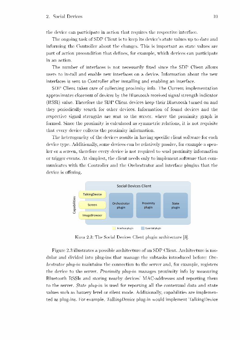
The heterogeneity of the devices results in having speci�c client software for each
device type. Additionally, some devices can be relatively passive, for example a spea-
ker or a screen, therefore every device is not required to send proximity information
or trigger events. At simplest, the client needs only to implement software that com-
municates with the Controller and the Orchestrator and interface plugins that the
device is o�ering.
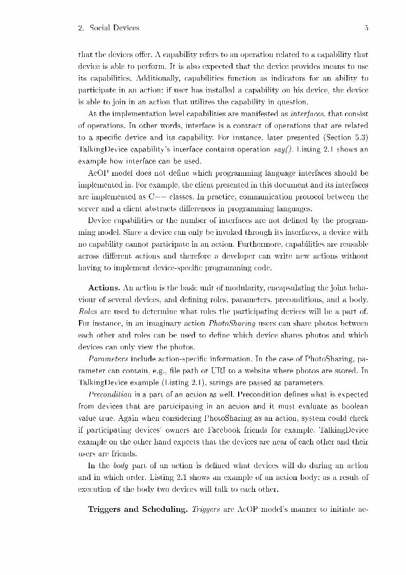
Kuva 2.3: The Social Devices Client plugin architecture [3].
Figure 2.3 illustrates a possible architecture of an SDP Client. Architecture is mo-
dular and divided into plug-ins that manage the subtasks introduced before: Orc-
hestrator plug-in maintains the connection to the server and, for example, registers
the device to the server. Proximity plug-in manages proximity info by measuring
Bluetooth RSSIs and storing nearby devices' MAC-addresses and reporting them
to the server. State plug-in is used for reporting all the contextual data and state
values such as battery level or silent mode. Additionally, capabilities are implemen-
ted as plug-ins. For example, TalkingDevice plug-in would implement TalkingDevice

2. Social Devices 11
interface. The implementation of the SDP Client for an embedded system that is
introduced in this paper somewhat follows the architecture seen in Figure 2.3.
2.4.3 Controller Component
The Controller acts as a front-end for the SDP meaning it provides all the neces-
sary interfaces for accessing and modifying data on the server side. For example, it
provides a REST (Representational state transfer) API but a web user interface as
well. Furthermore, the Controller manages data such as actions, interfaces, triggers,
devices and user model, within the server side. Managing proximity information is
decentralized for the Proximity subcomponent.
As seen in Figure 2.2, the developer de�nes new interfaces and actions. This is
done in Python, and new code can be uploaded either using a REST API or a
web user interface. The Controller parses the interfaces and action descriptions and
stores them in a database. Furthermore, user can download the SDP client from
the Controller and register their devices to the Controller. The state values, which
indicated device's role in an action, are also stored in the Controller.
The Proximity subcomponent maintains the proximity information of the devices
registered to the SDP. Information is stored as mathematical graph V = (N,E),
where N is a set of nodes and E is a set of edges. Graph gets updated when devices
send their RSSI values and by using these signal strengths the Proximity component
calculates new distances that are attached to the edges between the nodes. To know
how old the proximity information is, distance is tagged with a timestamp, which
indicates when node was created or refreshed.
Utilizing REST, the Proximity subcomponent o�ers interface for querying proxi-
mities with respect to a speci�c device. For example, it is possible to search devices
around a device within a given radius. In practice, such subgraph is only an approxi-
mation: all the nodes are not always connected and devices might be closer than
subgraph indicates.
Additionally, the Controller provides a REST API for the SDP Client to update
its device's proximity data and state values. Correspondingly a similar REST API
is used for triggers as well. When the Controller receives a trigger, it processes it
and forms a request that is sent to the Con�gurator. The request holds information
on con�guration model and state values of all the devices including the ones within
the proximity of the device that sent the trigger. The Con�gurator processes the
request and chooses an action and assigns action-speci�c roles to each participating
device. The Con�gurator component and its tasks are explained more thoroughly in
the following subsection.

2. Social Devices 12
2.4.4 Con�gurator Component
The decision whether an action can be executed for a set of devices is up to the
Con�gurator Component. The Con�gurator Component needs to consider several
issues when making the decision: Devices need to implement certain interfaces for
a speci�c role and state value conditions must be met as well. In addition, the
Con�gurator Component must assign roles in an action for each device. This set
of decisions can be formulated as a con�guration problem where certain action and
con�guration model, the task is to �nd a valid con�guration of devices and their
assignments to the action roles. The con�guration model includes, for example,
action preconditions and interface de�nitions.
The group of devices that are close to each other is dynamic since devices may
be constantly moving. Therefore the con�guration model needs to be generated at
runtime based on the information of the triggered actions and participating devices.
In addition to the con�guration model, the �nal con�guration depends on the con�-
guration selections as well. The con�guration selections consist of devices' state va-
lues. The Con�gurator acts as a service that �nds a valid con�guration based on the
con�guration model and selections and returns the con�guration to the Controller.
Kuva 2.4: An illustration of the con�guration model generation process [2].
Kuva 2.5: An illustration of the con�guration selection generation process [2].
To produce a valid con�guration, the Con�gurator utilizes the smodels inference
2. Social Devices 13
engine. Smodels is a general-purpose inference tool based on stable model semantics
of logic programs [4]. As Figure 2.4 illustrates, the tool takes action preconditions
and proximity devices as input and generates Weight Constraint Rule Language
(WCRL, a general-purpose knowledge presentation language) con�guration model
using WCRL con�guration model template. WCRL con�guration selections are pro-
duced similarly using state values of proximity devices as input and utilizing WCRL
con�guration selection template as seen in Figure 2.5. The Con�gurator uses both,
WRCL con�guration model and selections, to form a valid con�guration that results
in assigning speci�c devices for speci�c roles of the action.
2.4.5 Orchestrator Component
Devices in the same proximity set can be considered as actors in an action. Actors
are responsible for their own local operations regarding an action but coordination
between actors is up to the server side, the Orchestrator Component to be exact.
The Orchestrator acts as centralized server that handles executing the actions.
The actual code to be executed is described in the action body part of the action
description. Executing actions utilizes services of the devices that the Controller
has selected. Services have interfaces for operations that de�ne what the device is
capable to do when an operation is invoked.
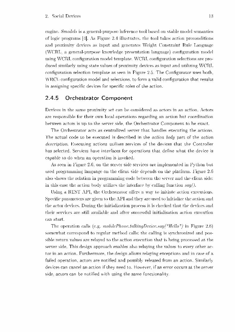
As seen in Figure 2.6, on the server side services are implemented in Python but
used programming language on the client side depends on the platform. Figure 2.6
also shows the relation in programming code between the server and the client side:
in this case the action body utilizes the interface by calling function say().
Using a REST API, the Orchestrator o�ers a way to initiate action executions.
Speci�c parameters are given to the API and they are used to initialize the action and
the actor devices. During the initialization process it is checked that the devices and
their services are still available and after successful initialization action execution
can start.
The operation calls (e.g. mobilePhone.talkingDevice.say("Hello") in Figure 2.6)
somewhat correspond to regular method calls: the calling is synchronized and pos-
sible return values are relayed to the action execution that is being processed at the
server side. This design approach enables also relaying the values to every other ac-
tor in an action. Furthermore, the design allows relaying exceptions and in case of a
failed operation, actors are noti�ed and possibly released from an action. Similarly
devices can cancel an action if they need to. However, if an error occurs at the server
side, actors can be noti�ed with using the same functionality.
2. Social Devices 14
Kuva 2.6: Execution of service operations. [2].
2.5 Orchestrator.js
This section presents an alternative implementation for the SDP that supports Social
Devices. Orchestrator.js is the next iteration of the SDP that, for example, is imple-
mented in a cloud service unlike the SDP [5]. Additionally, Orchestrator.js midd-
leware is designed to reduce the complexity of the architecture to improve compa-
tibility with embedded devices and to improve prototyping abilities [5]. Next, the
architecture of Orchestrator.js is presented.
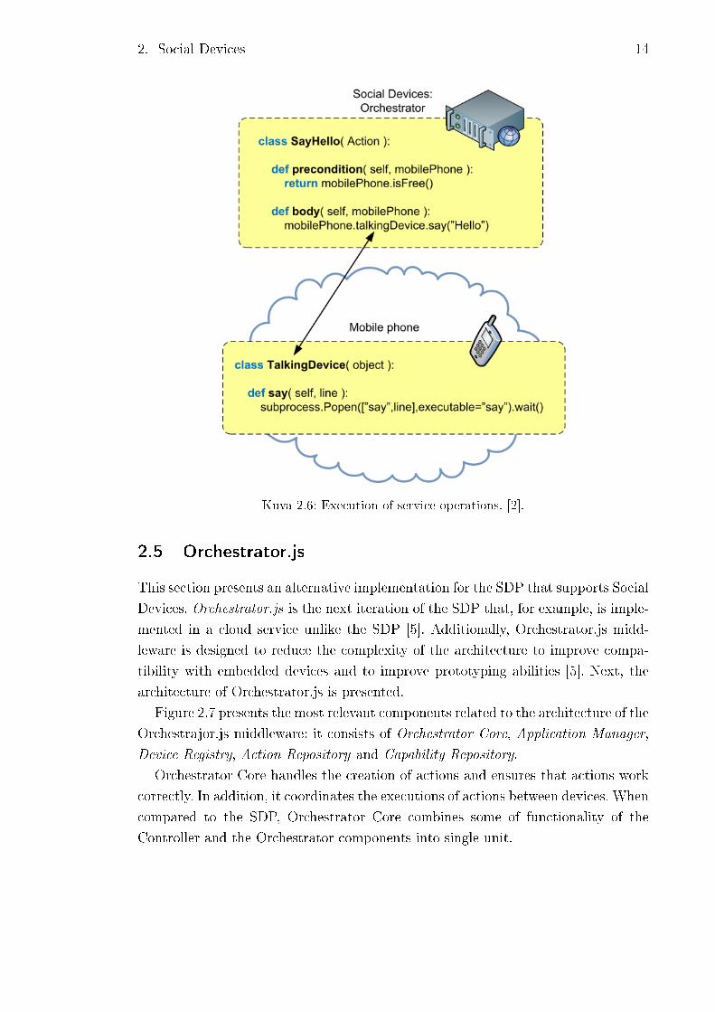
Figure 2.7 presents the most relevant components related to the architecture of the
Orchestrajor.js middleware: it consists of Orchestrator Core, Application Manager,
Device Registry, Action Repository and Capability Repository.
Orchestrator Core handles the creation of actions and ensures that actions work
correctly. In addition, it coordinates the executions of actions between devices. When
compared to the SDP, Orchestrator Core combines some of functionality of the
Controller and the Orchestrator components into single unit.
2. Social Devices 15
Kuva 2.7: Orchestrator.js middleware.
The Application Manager stores and executes applications and provides user
interface for starting and stopping applications. The application utilizes the help
of observers that monitor changes in various sources. These sources can be, for
example, websites or RSS feeds.
The Device Registry functions similarly as the Controller component in the SDP:
it preserves contextual information about devices and keeps proximity graph up to
date. In addition, it provides suitable API that o�ers noti�cations about devices'
context data.
The Action Repository is reserved for storing the action de�nitions. In this imple-
mentation de�nitions are written in JavaScript holding preconditions and error hand-
ling. Additionally program code includes description how the devices function toget-
her. In contrast to the SDP, the Orchestrator component was used to contain action
de�nitions.
The Capability Repository includes descriptions for each capability. In practice,
descriptions only de�ne what methods (and parameters) need to be implemented.
The actual implementation depends on the device and the language used and it is
up to the developer how the implementation is done. This kind of approach can
simplify designing new applications when there's explicit agreement which methods
certain capability requires, which was not the case in the SDP.

2. Social Devices 16
2.6 Related Work
Various other research �elds are somewhat related to Social Devices. For example,
smart spaces resembles Social Devices as they both make use of the proximity of
devices when providing services. Especially social devices, which are stationary, func-
tion as smart spaces like elevator or meeting room screen. What distinguishes these
two, is that Social Devices are not tied to a speci�c location nor speci�c devices.
The philosophy behind the actions is also rather di�erent: Social Devices tend to
provide more user-visible behaviour instead of just background services. This is also
in contrary to pervasive computing and Internet of Things which intend to minimize
user distraction [6]. For example, Social Devices precisely might interrupt social in-
teractions and therefore is in contrast to pervasive computing that has the vision of
indistinguishable form or minimal user distraction [6].
In comparison to Web Services or Service-Oriented Architectures (SOAs) [7],
Social Devices utilizes resources and capabilities of various physically co-located
devices and the proximity of the devices in a user observable manner rather relying
services that are produced on the server side.
17
3. COMMUNICATION PROTOCOLS IN THE
SOCIAL DEVICES PLATFORM
This chapter aims at clarifying the communication between the client and the server.
The sections introduce few key concepts and explain their reliance to the software.
Kuva 3.1: OSI model.
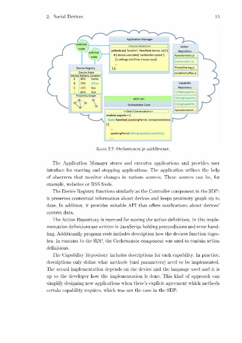
The concepts of this chapter are mainly related to the Open Systems Intercon-
nection (OSI) model. OSI model (Figure 3.1) is a conceptual model that divides
internal functions of a communication system into abstraction layers [8]. Abstrac-
tion layers are grouped into seven logical layers that provide services for the layer
above it and it uses services provided by the layer under. The following sections int-
roduce protocols that belong to transport, session and application layers of the OSI
model. Sections 3.1, 3.2,3.3 and 3.4 discuss Transmission Control Protocol, Hyper-
text Transfer Protocol, Websocket and Socket.IO protocol, respectively. Section 3.5
is reserved for presenting the protocol that is used in OrchestratorJS.
3. Communication Protocols in the Social Devices Platform 18
3.1 Transmission Control Protocol
Transmission Control Protocol, commonly known as TCP, belongs to the core pro-
tocols of the Internet protocol suite (IP). TCP is a part of transport layer and it
provides reliable, ordered and error-checked transferring of packets between pro-
grams that run on di�erent computers and that are connected through a network.
Packets consists of data and of header that describes packet's source, destination
and control information. [9]
TCP acts between IP and application layer. It accepts any data sent from an
application. TCP takes care of sending data by breaking it into appropriate pieces
suitable for IP. When receiving data, TCP makes sure, for example, that the data
is in right order and the passes the data for the right target application.
3.2 Hypertext Transfer Protocol
The Hypertext Transfer Protocol (HTTP) is an application-level protocol for di-
stributed, collaborative, hypermedia information systems that is layered on top of
TCP [10]. It is widely used protocol for data communication for the World Wide Web
(WWW). HTTP is the actual protocol for exchanging or transferring hypertext that
usually carries information of websites in the form of HTML-�les. In this context,
hypertext includes information about SDP-speci�c communication protocol.
Hypertext and its contents di�er from the normal use but HTTP still functions in
traditional way as a request-response protocol. Request-response is a basic method
used for computers to communicate with each other, which works as follows: a
computer shows interested in some data by sending a request and a target computer
simply responds to the request. In the case of HTTP, normally a computer sends
a request for a server for an HTML-�le and if the request is successful, the server
responses by sending the requested HTML-�le. Similarly in the SDP if, for example,
device wants to register itself to the server, it sends a request holding information
about the device and the server responds to the request.
Comet is an application model that allows a web server to push data to a client
without the browser explicitly requesting it [11]. This can done by AJAX Long-
Polling that functions as follows. A client requests normally but the response is put
on hold until there is new information available. The server responds when there is
new information available and the client immediately responds starting a new cycle.
The approach described is used in the Social Devices Platform.
3.3 Websocket
Websocket is rather new protocol that provides, unlike HTTP, full-duplex (simul-
taneous communication in both directions) communication over a single TCP con-
3. Communication Protocols in the Social Devices Platform 19
nection [12]. Websocket was developed mainly to answer real-time requirements of
various applications. The client and the server are able to send messages at any time
and they must handle message receiving asynchronously.
The advantage of Websocket connection over HTTP connection is that after initial
handshake, which is done over HTTP, Websocket has lower overhead per message.
Additionally, the transmission of packets is faster as one data frame can be sent as
soon as one frame is �lled and there's no need to know the complete length of data
beforehand.
3.4 Socket.IO protocol
Socket IO adds another abstraction layer on top of Websocket and HTTP. Socket IO
functions nearly similarly to Websocket but adds some additional features: It o�ers
disconnection detection through heartbeats and enables optional acknowledgements.
Socket IO also has reconnection support with bu�ering. [13]
As Socket IO protocol works typically on top of Websocket, connection is started
with handshake, which is done over HTTP. After the handshake, a client receives a
session id that will be used for opening connections. Client also receives information
about how often heartbeats are sent and when socket is considered disconnected
after transport connection has closed.
After the initial handshake, the actual payload consists of messages that imple-
ment the protocol in question. The messages can be seen in Table 3.1.
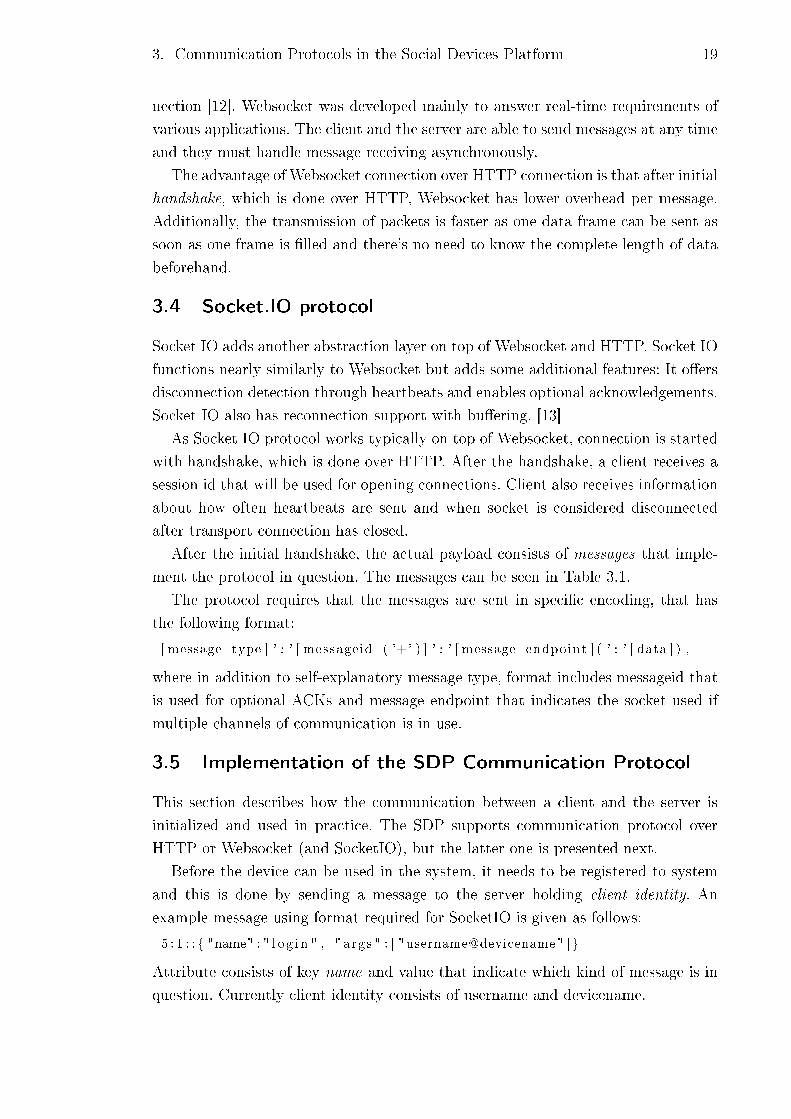
The protocol requires that the messages are sent in speci�c encoding, that has
the following format:
[ message type ] ' : ' [ messageid ( '+' ) ] ' : ' [ message endpoint ] ( ' : ' [ data ] ) ,
where in addition to self-explanatory message type, format includes messageid that
is used for optional ACKs and message endpoint that indicates the socket used if
multiple channels of communication is in use.
3.5 Implementation of the SDP Communication Protocol
This section describes how the communication between a client and the server is
initialized and used in practice. The SDP supports communication protocol over
HTTP or Websocket (and SocketIO), but the latter one is presented next.
Before the device can be used in the system, it needs to be registered to system
and this is done by sending a message to the server holding client identity. An
example message using format required for SocketIO is given as follows:
5 : 1 : : { "name" : " l o g i n " , " args " : [ "username@devicename" ] }
Attribute consists of key name and value that indicate which kind of message is in
question. Currently client identity consists of username and devicename.

3. Communication Protocols in the Social Devices Platform 20
Taulukko 3.1: The messages in Socket.IO protocol [13].
Type Explanation(0) Disconnect Signals disconnection. If no endpoint is speci�ed, discon-
nects the entire socket.(1) Connect Only used for multiple sockets. Signals a connection to
the endpoint. Once the server receives it, it is echoedback to the client.
(2) Heartbeat Sends a heartbeat. Heartbeats must be sent within theinterval negotiated with the server. It is up to the clientto decide the padding (for example, if the heartbeat ti-meout negotiated with the server is 20s, the client mightwant to send a heartbeat every 15s).
(3) Message Regular message.(4) JSON Message A JSON encoded message.(5) Event An event is like a json message, but has mandatory name
and args �elds. name is a string and args an array.(6) ACK An acknowledgment contains the message id as the mes-
sage data. If a + sign follows the message id, it is treatedas an event message packet.
(7) Error Error message.(8) Noop No operation. Used for example to close a poll after the
polling duration times out.
After initializations are done, a device starts to listen if there has an action
started. A method invocation by server has the following format:
5 : 1 : : { "name" : "methodcal l " , " args " : [
action_id , methodcal l Id , capabil ityName , methodcallName ,
[ arguments ] ] }
Before the device can join in an action, it is checked that the device meets capability
requirements (capabilityName) and if it does, the device changes its method call id
to match the current method call id received in the message. Method call id is used
to keep track of the execution status of an action. In other words, it keeps all of
the participating devices synchronized regarding an action. When the action execu-
tion continues, the device updates its method call id accordingly. MethodcallName
is rather self-explanatory, arguments on the other hand includes method-speci�c
parameters.
Responsing to a method call has same attributes as the request but also includes
return value:
5 : 1 : : { "name" : "methodca l l r e sponse " , " args " : [
action_id , methodcal l Id , re turnva lue , re turnva luetype ,
[ arguments ] ] }

3. Communication Protocols in the Social Devices Platform 21
Return value can be of any type but the type must be informed in the corresponding
parameter. If action execution fails or the client wants to raise an exception for
another reason, it is done with following message:
5 : 1 : : { "name" : " except ion " , " args " : [
action_id , methodcal l Id , c l i e n t i d e n t i t y , reason ] }
When the device changes its state, the information is sent to the server with
context message:
5 : 1 : : { "name" : " context_data" , " args " : [
action_id , c l i e n t i d e n t i t y , [ medata ] ] }
Metadata includes necessary state changes.
For instance, when running an example that involves a device registering itself,
the server invoking a method and the device responding to the request, messages
are as following:
1. 5:1::{"name":"login", "args":["akseli@arduino"]}
2. 5:2::{"name":"methodcall","args":[78,47,"TalkingCapability","say",["Hi"]]}
3. 5:3::{"name":"methodcallresponse","args":[121,47,"TRUE","BOOLEAN"]}
In step 1, the device gets registered with speci�c identity. The device's capability's
method say() is invoked with a string parameter in step 2. In the response message,
the device has updated its action id and method id to match the invocation (step 3).
Additionally, the response has a return value, simply a boolean value in this case.
22
4. ARDUINO PLATFORM
In this chapter the Arduino platform is introduced and some argumentation is shown.
Additionally, the platform and all the related components are introduced. Further-
more, some key concepts regarding designing software for an embedded systems are
presented as well.
Section 4.1 discusses about why Arduino platform was chosen over other options
and which components developing toolchain consists of. In Section 4.2, the target de-
vice for the client software is presented. The components WiFi Shield and Bluetooth
module are introduced in Sections 4.3 and 4.4, respectively.
4.1 Motivation
Arduino platform is intended to make the development of interactive objects or en-
vironments more accessible [14]. The hardware consists of components that are open
source, meaning their circuit diagrams or drivers for example, are freely available.
Arduino has its own programming language (based on Wiring) that simpli�es
many functions like input or output operations in a user friendly way without con-
�guring microcontroller's registries for instance. As a toolchain, Arduino uses GNU
and AVR Libc to compile programs. Avrdude is an utility for uploading the actual
programming code into the program memory. [14]
Arduino was chosen as a target embedded system mainly due to easy prototyping
and open source nature of the platform. The availability of the accessories such as
WiFi-shield was also a key factor. Another embedded system would have been, for
example, very popular Raspberry Pi : the device is capable of running a Linux, has
networking capabilities and enough amount of general IO-ports. Development of
the client would have been also as straightforward as developing for any desktop
computer. Still Raspberry Pi was left out, since developing a software for Raspberry
Pi would have been "too straightforward"and would not have served one of the
purposes this thesis has learning developing a software for an embedded system.
Raspberry Pi o�ers much more powerful hardware and it has, for instance, roughly
50 times faster processor and 50 000 times more RAM than average Arduino board.
As developing software for an embedded system usually involves challenges regarding
performance and memory consumption, Raspberry Pi would easily handle this sort
of software.
4. Arduino platform 23
Arduino o�ers several prototyping boards that di�er in various ways. For instance,
microprocessor, amount of analog and digital ports and amount of SRAM or Flash
memories each depend on the Arduino board. Almost every Arduino is suitable to
run the Social Devices client, but currently the amount of RAM is the deciding
factor.
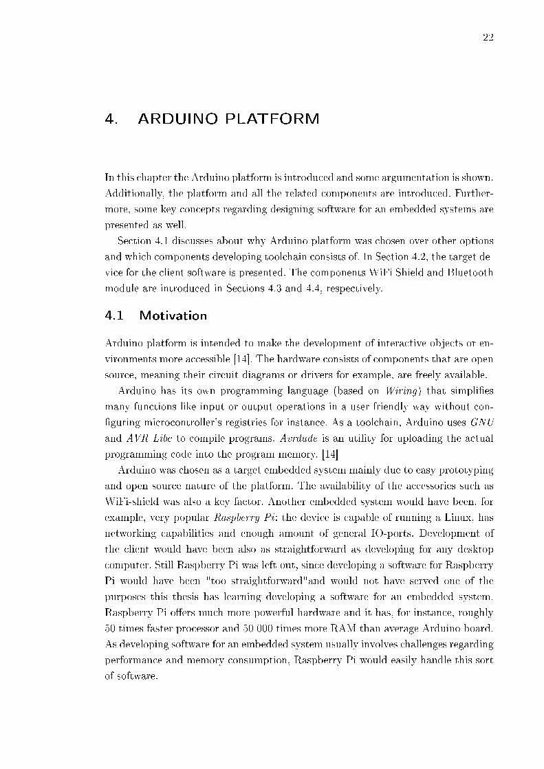
Usually embedded systems like an Arduino board and its microprocessor are de-
signed with Harvard architecture. As Figure 4.1 illustrates, in Harvard architecture
instructions and data are stored in di�erent physical memories. For example, the
microprocessor ATmega1280, used in the Arduino Mega, utilizes Harvard architec-
ture and uses di�erent memory technologies for data and program memory. Atmega
1280 stores the actual executable code in the program memory, which in this ca-
se is implemented with Flash technology. Correspondingly, SRAM (Static Random
Access Memory) is used for data memory. Data memory consists mainly of data
that is manipulated during run-time.
Kuva 4.1: Harvard architecture.
4.2 Arduino Mega
This section introduces the Arduino Mega that was chosen as the prototype board
mainly due to having the largest RAM amount in the Arduino family. Like most of
the Arduino boards, Mega is also equipped with Atmel's 8-bit microprosessor. Table
4.1 lists few features of Arduino Mega.
To highlight some of these, the size of SRAM is rather high since typically Arduino
boards have an average of 1 KB SRAM and therefore our program is easily �t into
the SRAM [14]. Operating voltage is ideal considering that it can be powered by a
regular battery and no external power source is necessarily needed. For prototyping
purposes the amount of analog or digital input pins suits rather well. Considering
that by attaching, for instance, a simple LCD panel can take up to 10 pins so more
modest Arduinos will have issues with the lack of pins. Processor's clock speed of
16 MHz turned out to be more than enough as our program does not include any
intensive processing.
4. Arduino platform 24
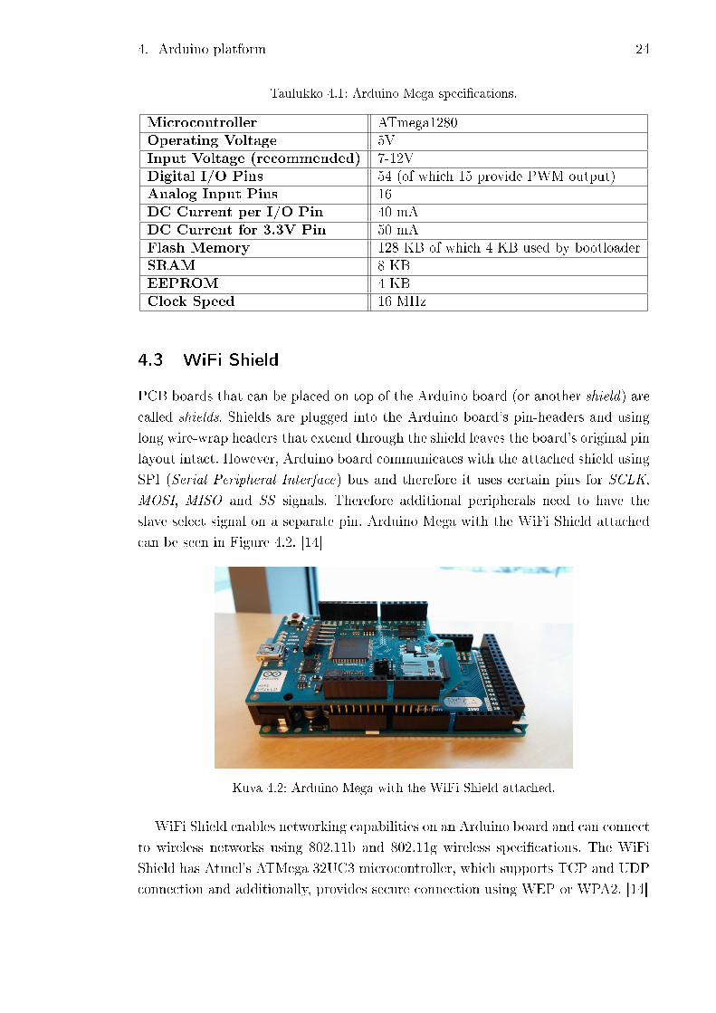
Taulukko 4.1: Arduino Mega speci�cations.
Microcontroller ATmega1280Operating Voltage 5VInput Voltage (recommended) 7-12VDigital I/O Pins 54 (of which 15 provide PWM output)Analog Input Pins 16DC Current per I/O Pin 40 mADC Current for 3.3V Pin 50 mAFlash Memory 128 KB of which 4 KB used by bootloaderSRAM 8 KBEEPROM 4 KBClock Speed 16 MHz
4.3 WiFi Shield
PCB boards that can be placed on top of the Arduino board (or another shield) are
called shields. Shields are plugged into the Arduino board's pin-headers and using
long wire-wrap headers that extend through the shield leaves the board's original pin
layout intact. However, Arduino board communicates with the attached shield using
SPI (Serial Peripheral Interface) bus and therefore it uses certain pins for SCLK,
MOSI, MISO and SS signals. Therefore additional peripherals need to have the
slave select signal on a separate pin. Arduino Mega with the WiFi Shield attached
can be seen in Figure 4.2. [14]
Kuva 4.2: Arduino Mega with the WiFi Shield attached.
WiFi Shield enables networking capabilities on an Arduino board and can connect
to wireless networks using 802.11b and 802.11g wireless speci�cations. The WiFi
Shield has Atmel's ATMega 32UC3 microcontroller, which supports TCP and UDP
connection and additionally, provides secure connection using WEP or WPA2. [14]
4. Arduino platform 25
Arduino provides a library that has all the necessary classes to scan available
networks, connecting to a network and to establish a connection to a server and
exchange data with it. Using of WiFi Shield is rather straightforward:
• scanNetworks() looks for networks around and returns their SSIDs,
• begin(ssid, pass) is used for connecting to certain network,
• disconnect() disconnects from the current network,
• connect(URL, port makes TCP connection to an URL or IP,
• connected() used to check if the client is connected,
• available() turns boolean-value indicating if there is data available to read,
• write(data) writes data to the server the client is connected to.
Besides WiFi Shield, Arduino can be connected to the Internet using Ethernet
Shield.
4.4 Bluetooth Module
The SDP concept presumes that devices are locally aware of each other. At the
current moment Bluetooth technology is used for sensing other, nearby devices.
The Bluetooth module used in the project was RN-42 manufactured by Roving
Networks. The module is compatible with Bluetooth standards 2.1, 2.0, 1.2 and 1.1,
therefore it was quali�ed enough for the purpose as the module is discoverable and
is capable of scanning other devices [15]. The module is rather energy e�cient as
it consumes only 26 µA while idling (still staying discoverable) and 30 mA while
transmitting data. Low power consumption can be very important issue since em-
bedded systems used for the SDP are not necessarily stationed and therefore they
are usually powered by a battery [15].
The actual Bluetooth module is soldered onto a PCB board that o�ers voltage
regulators and connectors for example. The schema can be seen in Figure 4.3. The
module communicates through serial connection and therefore it needs its trans-
mit and receive pins attached to the other device's corresponding pins. In this case
Arduino Mega o�ers hardware serial port on pins 0-1, 14-15, 16-17 and 18-19. Ty-
pically for Arduino boards, the amount of hardware serial ports is very limited and
it might be the case that hardware serial is not available. To avoid this problem, it
is possible to communicate with the module through software serial, which means
that hardware connection is being emulated by software. This was also tested but
resulted in having more unstable and slower connection.

4. Arduino platform 26
Kuva 4.3: Schema of Bluetooth module and Arduino Mega hooked up.
In the schema (Figure 4.3), the Bluetooth module is powered through Arduino
but to reduce the load on the board, external power source could be useful. CTS
(Clear To Send) and RTS (Request To Send) pins are normally used for hardware
�ow control but they were not needed so they were short circuited to avoid any noise
that could be interpret as a signal.

27
5. SOCIAL DEVICES CLIENT FOR ARDUINO
In this chapter an implementation of the Social Devices Platform -client for the Ar-
duino platform is introduced. The chapter is divided followingly: Section 5.1 discus-
ses about general design methods and how the client is implemented to be as easy
as possible to use in developer's point of view. The actual implementation is shown
in Section 5.2. In the later part of the chapter an implementation of TalkingDevice
interface and how the client can be utilized in practice are shown in Section 5.3.
Future work is presented in Section 5.4 and the chapter is summarized in Section
5.5.
5.1 General design paradigms
One of the �rst design decisions was considering whether to use an operating system
or not. An operating system would have allowed, for example, using of tasks that
would suit well with the Social Devices architecture: typical scenario would include,
for instance, an Orchestrator, a Proximity and State modules that have their own
speci�c task and they run parallel. Additionally, if the device is involved in an action,
the execution of the code related to the implementation of an interface would have
to be handled as well. Executing parallel code led to a problem: will the performance
be enough? For example, in the case of capability TalkingDevice (see Section 5.3),
users expect nearly instant response and slow execution hinders the user experience.
Keeping mind that the coordination of the devices is cloud-based that adds latency
in itself, therefore the execution of the device needed to be as fast as possible. This
resulted in making the execution sequential rather than parallel, so the need of an
operating system became obsolete. Additionally, RAM is a valuable resource in an
embedded system and considering an operating system always utilizes some of the
RAM, it was deciced to implement the system without an operating system.
In contrast to an ideal solution where updating proximity info, connection to the
server and possible execution of an action happen parallel, the current implementa-
tion behaves as follows (Figure 5.1). After booting, the device is initialized and it
connects to a network and possibly initializes any attached peripherals. Initializa-
tion is followed by registering the device to the server side and at the same time
the device publishes its interfaces. At this point proximity data is gathered via the
Proximity plug-in and state values are updated by the State plug-in. Next, the client
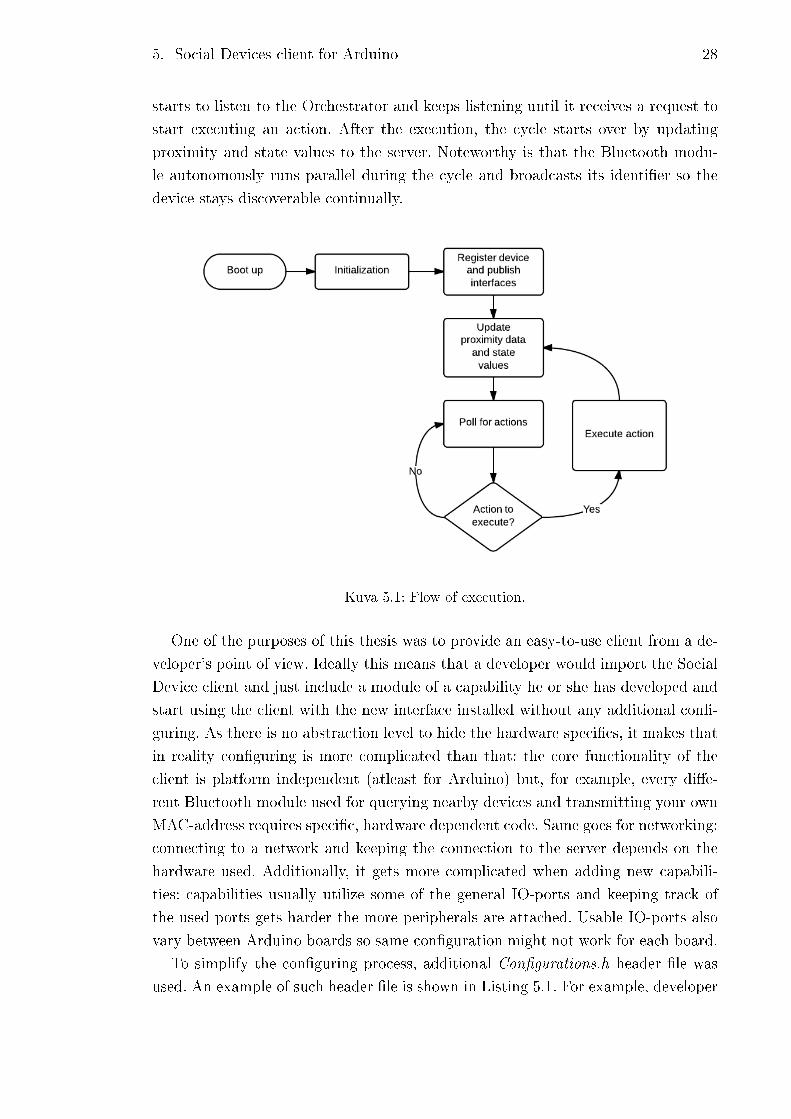
5. Social Devices client for Arduino 28
starts to listen to the Orchestrator and keeps listening until it receives a request to
start executing an action. After the execution, the cycle starts over by updating
proximity and state values to the server. Noteworthy is that the Bluetooth modu-
le autonomously runs parallel during the cycle and broadcasts its identi�er so the
device stays discoverable continually.
Kuva 5.1: Flow of execution.
One of the purposes of this thesis was to provide an easy-to-use client from a de-
veloper's point of view. Ideally this means that a developer would import the Social
Device client and just include a module of a capability he or she has developed and
start using the client with the new interface installed without any additional con�-
guring. As there is no abstraction level to hide the hardware speci�cs, it makes that
in reality con�guring is more complicated than that: the core functionality of the
client is platform independent (atleast for Arduino) but, for example, every di�e-
rent Bluetooth module used for querying nearby devices and transmitting your own
MAC-address requires speci�c, hardware dependent code. Same goes for networking:
connecting to a network and keeping the connection to the server depends on the
hardware used. Additionally, it gets more complicated when adding new capabili-
ties: capabilities usually utilize some of the general IO-ports and keeping track of
the used ports gets harder the more peripherals are attached. Usable IO-ports also
vary between Arduino boards so same con�guration might not work for each board.
To simplify the con�guring process, additional Con�gurations.h header �le was
used. An example of such header �le is shown in Listing 5.1. For example, developer

5. Social Devices client for Arduino 29
instantly sees what ports are already used and can check if the selected ports meet
the board requirements. Additionally, a developer can disable or enable an interface
easily: in the example con�g header, commenting out the line #de�ne TALKING-
DEVICE would leave out the implementation from the build in case it is not needed.
Listing 5.1: Con�gurations.h
#ifndef CONFIGS_h
#define CONFIGS_h
#define BLUETOOTHMODULE
#ifde f BLUETOOTHMODULE
#de f i n e PORTRX 8
#de f i n e PORTTX 9
#endif
#define WIFISHIELD
//#de f i n e ETHERNETSHIELD
#define TALKINGDEVICE
#ifde f TALKINGDEVICE
#de f i n e BEAKPORT 2
#de f i n e LEFTWINGPORT 3
#de f i n e RIGHTWINGPORT 4
#define DEVICENAME " akse l i@ardu ino "
#define ORCHESTRATORADDRESS " s o c i a l . c s . tut . f i : 8000 "
#endif
#endif
Additionally developer can modify this �le if, e.g., the address of the server chan-
ges or developer wants to change other attributes. This approach simpli�es the work
needed by the developer as there is no need to edit the actual programming code
�les.
5.2 Client architecture and implementation
The client architecture loosely follows the architecture seen in Figure 2.3. In contrast
to the plug-in architecture, the separate modules can not be considered as plug-ins
as they are tightly coupled with each other and can not be removed from the build.
Arduino platform provides the necessary tools to implement the program either
in C or in C++. The most intuitive approach was to implement the needed modules
as classes and therefore the program is written in C++. Figure 5.2 includes the
class diagram. The client architecture is divided into �ve classes: Client, Initializer,
Orchestrator, Proximity and State.
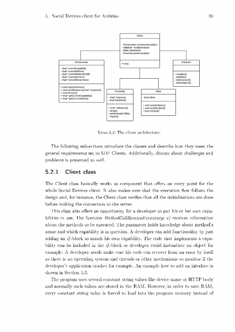
5. Social Devices client for Arduino 30
Kuva 5.2: The client architecture.
The following subsections introduce the classes and describe how they meet the
general requirements set to SDP Clients. Additionally, discuss about challenges and
problems is presented as well.
5.2.1 Client class
The Client class basically works as component that o�ers an entry point for the
whole Social Devices client. It also makes sure that the execution �ow follows the
design and, for instance, the Client class veri�es that all the initializations are done
before making the connection to the server.
This class also o�ers an opportunity for a developer to put his or her own capa-
bilities in use. The function MethodCallReceived(eventargs e) receives information
about the methods to be executed. The parameter holds knowledge about method's
name and which capability is in question. A developer can add functionality by just
adding an if -block to match his own capability. The code that implements a capa-
bility can be included in the if -block or developer could instantiate an object for
example. A developer needs make sure his code can recover from an error by itself
as there is no operating system and threads or other mechanisms to monitor if the
developer's application crashes for example. An example how to add an interface is
shown in Section 5.3.
The program uses several constant string values like device name or HTTP body
and normally such values are stored in the RAM. However, in order to save RAM,
every constant string value is forced to load into the program memory instead of

5. Social Devices client for Arduino 31
the data memory. This is done in the Client class by using various keywords that
are de�ned in a special library:
prog_uchar variableName [ ] PROGMEM = {"Example s t r i n g . " } ,
where prog_uchar indicates that the variable's (variableName, in this case) data-
type is an unsigned char. The keyword PROGMEM can only be used with certain
datatypes and its sole purpose is to tell the compiler to put the variable into program
memory instead of data memory. The logic behind all this is to save data memory
as Arduino boards have typically more (atleast 16 times) program memory space.
In the example variable, transferring the variable into program memory would save
15+1 bytes, which does not sound much but is almost one percent of Arduino Uno's
RAM for example. Considering that this program has dozens of similar constant
strings, this sort of approach was very e�ective way to save data memory.
5.2.2 Initializer class
Embedded systems usually involve many peripherals and it is hardly ever a case
where processor acts alone. Like in this project, there are many devices attached
that each one has its unique way of con�guring and initialising. This class' main
purpose was to o�er a single place where the devices get initialised and con�gured.
First of all, sometimes it matters when and in what order the devices get initialised
and by putting them in the same place reduces possible misbehaviours. Secondly,
gathering all the initialisations to the same place in the code helps the developer to
add new devices as it is rather explicit where he or she has to modify the code to
get the device working.
The class interface can be seen in the Figure 5.2 that shows the class diagram. To
keep it as simple as possible for the class' user, using the class is very straightforward:
I n i t i a l i z e r . I n i t i a l i z e ( )
does all the necessary initialisations. The implementation part takes care of all the
above mentioned requirements so users do not have to worry about anything. The
actual initializations are done in the private functions of the class, which are then
called in the function Initialize() in the right order.
Device-speci�c initializers depend heavily on used ports for example. In the cur-
rent implementation, constants, like port numbers, are not relayed as function para-
meters but they can be found from Con�gs.h-header �le that was introduced before.
5.2.3 Orchestrator class
This section introduces the implementation of the Orchestrator class. The imple-
mentation aims at ful�lling all the requirements set for an SDP Client, that can be
reviewed in Subection 2.4.2.
5. Social Devices client for Arduino 32
As Orchestrator class' main task was to communicate with the server, it was
intuitive to derive the class from the class that implemented the communication
protocol. In this project, the underlying communication protocols were HTTP and
SocketIO and therefore two implementations exist.
The version that was built on HTTP used a library by Adrian McEwen that
implemented the protocol in question [16]. SocketIO version was based on Bill Roy's
library of SocketIO protocol [17]. In both cases, Orchestrator class o�ers the same
interface to work with but the underlying components are di�erent.
Before making a connection to the Orchestrator, the Orchestrator class assumes
that the Arduino is already con�gured properly. After registering the device, Orc-
hestrator keeps monitoring the connection and if it receives information e.g. about
methods, that information is passed to the Client class where it can be handled. Ad-
ditionally, Orchestrator o�ers interfaces to pass information, return values or excep-
tions from the current actions to the server side. Orchestrator also makes sure that
the connection does not die while there is not any communication for a while by
sending heartbeats.
According to the Socket.IO protocol, the messages between client and the server
consist of JSON messages. Normally handling JSON messages is rather stress free
but when it comes to embedded systems, used libraries need a little more atten-
tion. Due to fragmentation (discussed more deeply in the Section 5.5), at one point
dynamic memory allocations needed to be removed and therefore traditional JSON
libraries could not be used. In the �nal version, Benoit Blanchon's JSON parser [19]
for Arduino that did not rely on malloc(), was used.
5.2.4 Proximity class
As stated before, Proximity class keeps track of surrounding devices by using Blue-
tooth. When a device is in discoverable mode it transmits the following information:
• Device name.
• Device class.
• List of services.
• Technical information (e.g. MAC-address).
We are interested in devices' names and Bluetooth MAC-address that are used for
identifying users and their devices respectively in an action for instance.
To keep it as simple as possible, Proximity class o�ers only one method to use.
Inquiry() executes an inquiry to scan around devices and passes the information
including the devices' MAC-addresses and their names to the server. Worth mentio-
ning is that the method call is synchronous meaning that the execution continues
5. Social Devices client for Arduino 33
after the method has �nished its own execution. In practice this can lead to problems
as scanning the devices is relatively slow operation (2-10 seconds) and during this
the system does not respond to action triggers for example. The SDP does not neces-
sarily require continuous scanning of the devices so in the current implementation
scanning is done only once after the boot up.
Each Bluetooth module needs to handled di�erently so the current version of
Proximity class supports only Roving Network's RN-42 -Bluetooth module. The
following pseudocode is used in the implementation:
1. Set up communication. This step is required for the communication between
the module and Arduino. In order for serial communication to work, both
devices need to be con�gured properly. Con�guring involves setting baud rates
to match and informing both devices that parity bit is not used.
2. Put the module in command mode. During this step, speci�c strings are
sent that will put the module in a mode where it accepts commands
3. Execute scan. The Bluetooth module starts scanning nearby devices.
4. Read and parse the scan results. If the scanning is successful, the module
responds with a result and the result is parsed in step 4.
5. Send results to server. Finally, the values including devices' MAC-addresses
and names are passed to the function that sends the information to the server.
Noteworthy is that the communication needed special attention: �rst the serial
communication was done programmatically but it had poor results as communica-
tion was slow and some times data got corrupted. Even though hardware serial was
used, data corruption still happened randomly for unknown reason. This was hand-
led by sending commands until the command was processed successfully. Another
issue was related to timings since the module could handle only one command at a
time so consecutive commands needed to be delayed by certain duration.
5.2.5 State class
State class' purpose is to keep states up to date. Additionally, it provides interfaces
to check what states the device currently has and o�ers methods to change them. An
example interface to handle device's state concerning silent mode is the following:
• bool isSilent()
• void setSilent(bool)
• void updateStates()
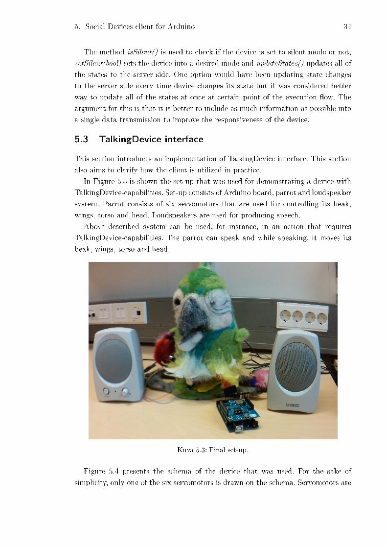
5. Social Devices client for Arduino 34
The method isSilent() is used to check if the device is set to silent mode or not,
setSilent(bool) sets the device into a desired mode and updateStates() updates all of
the states to the server side. One option would have been updating state changes
to the server side every time device changes its state but it was considered better
way to update all of the states at once at certain point of the execution �ow. The
argument for this is that it is better to include as much information as possible into
a single data transmission to improve the responsiveness of the device.
5.3 TalkingDevice interface
This section introduces an implementation of TalkingDevice interface. This section
also aims to clarify how the client is utilized in practice.
In Figure 5.3 is shown the set-up that was used for demonstrating a device with
TalkingDevice-capabilities. Set-up consists of Arduino board, parrot and loudspeaker
system. Parrot consists of six servomotors that are used for controlling its beak,
wings, torso and head. Loudspeakers are used for producing speech.
Above described system can be used, for instance, in an action that requires
TalkingDevice-capabilities. The parrot can speak and while speaking, it moves its
beak, wings, torso and head.
Kuva 5.3: Final set-up.
Figure 5.4 presents the schema of the device that was used. For the sake of
simplicity, only one of the six servomotors is drawn on the schema. Servomotors are
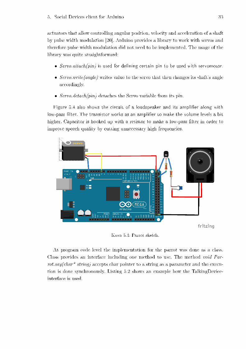
5. Social Devices client for Arduino 35
actuators that allow controlling angular position, velocity and acceleration of a shaft
by pulse width modulation [20]. Arduino provides a library to work with servos and
therefore pulse width modulation did not need to be implemented. The usage of the
library was quite straightforward:
• Servo.attach(pin) is used for de�ning certain pin to be used with servomotor.
• Servo.write(angle) writes value to the servo that then changes its shaft's angle
accordingly.
• Servo.detach(pin) detaches the Servo variable from its pin.
Figure 5.4 also shows the circuit of a loudspeaker and its ampli�er along with
low-pass �lter. The transistor works as an ampli�er to make the volume levels a bit
higher. Capacitor is hooked up with a resistor to make a low-pass �lter in order to
improve speech quality by cutting unnecessary high frequencies.
Kuva 5.4: Parrot sketch.
At program code level the implementation for the parrot was done as a class.
Class provides an interface including one method to use. The method void Par-
rot.say(char* string) accepts char pointer to a string as a parameter and the execu-
tion is done synchronously. Listing 5.2 shows an example how the TalkingDevice-
interface is used.
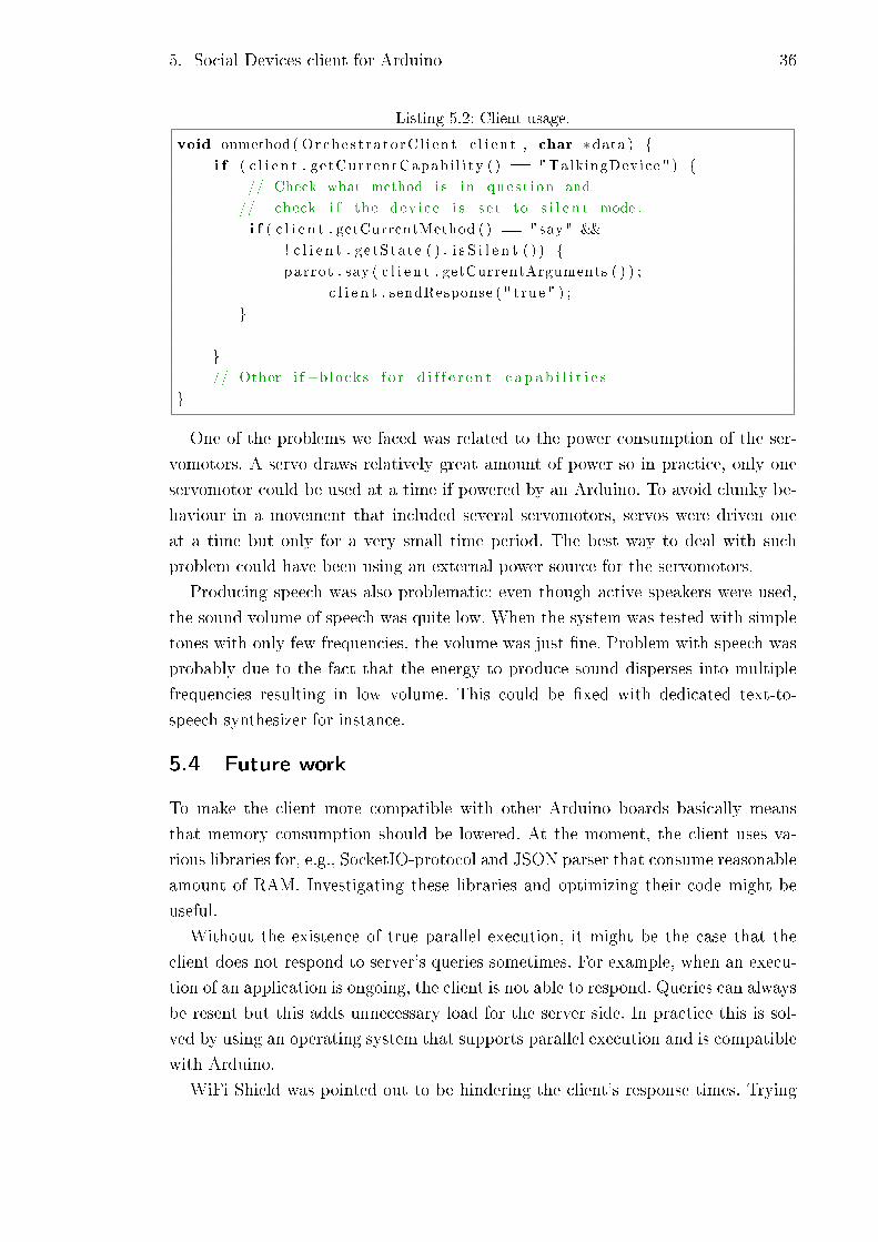
5. Social Devices client for Arduino 36
Listing 5.2: Client usage.
void onmethod ( Orche s t ra to rC l i en t c l i e n t , char ∗data ) {
i f ( c l i e n t . ge tCurrentCapab i l i ty ( ) == "TalkingDevice " ) {
// Check what method i s in ques t i on and
// check i f the dev i ce i s s e t to s i l e n t mode .
i f ( c l i e n t . getCurrentMethod ( ) == "say" &&
! c l i e n t . g e tS ta t e ( ) . i s S i l e n t ( ) ) {
parrot . say ( c l i e n t . getCurrentArguments ( ) ) ;
c l i e n t . sendResponse ( " t rue " ) ;
}
}
// Other i f−b locks f o r d i f f e r e n t c a p a b i l i t i e s
}
One of the problems we faced was related to the power consumption of the ser-
vomotors. A servo draws relatively great amount of power so in practice, only one
servomotor could be used at a time if powered by an Arduino. To avoid clunky be-
haviour in a movement that included several servomotors, servos were driven one
at a time but only for a very small time period. The best way to deal with such
problem could have been using an external power source for the servomotors.
Producing speech was also problematic: even though active speakers were used,
the sound volume of speech was quite low. When the system was tested with simple
tones with only few frequencies, the volume was just �ne. Problem with speech was
probably due to the fact that the energy to produce sound disperses into multiple
frequencies resulting in low volume. This could be �xed with dedicated text-to-
speech synthesizer for instance.
5.4 Future work
To make the client more compatible with other Arduino boards basically means
that memory consumption should be lowered. At the moment, the client uses va-
rious libraries for, e.g., SocketIO-protocol and JSON parser that consume reasonable
amount of RAM. Investigating these libraries and optimizing their code might be
useful.
Without the existence of true parallel execution, it might be the case that the
client does not respond to server's queries sometimes. For example, when an execu-
tion of an application is ongoing, the client is not able to respond. Queries can always
be resent but this adds unnecessary load for the server side. In practice this is sol-
ved by using an operating system that supports parallel execution and is compatible
with Arduino.
WiFi Shield was pointed out to be hindering the client's response times. Trying

5. Social Devices client for Arduino 37
di�erent network enabling shields could perhaps perform better. Another option
could be optimizing the WiFi Shield's drivers as they are open source.
5.5 Summary
One of the worst problems during development was fragmentation related to dynamic
memory allocation. Fragmentation means that after memory has been allocated and
freed dynamically multiple times, the memory is �lled with di�erent sizes of free or
allocated memory slots [18]. Figure 5.5 gives an example of fragmentation: system
has unallocated space available but it is distributed into three smaller chunks. This
can lead into a situation where free slots can not satisfy the application's demands
anymore. Typically the problem is related to memory allocation routines and there
is not much developer can do to avoid it [18].
Kuva 5.5: Memory fragmentation due to dynamic memory allocation.
Problems occurred when client had run successfully for a 5 to 10 minutes: �rst
the debug messages into terminal got corrupted and then the whole program cras-
hed which resulted in Arduino booting itself. Fragmentation was detected after out-
putting free memory into terminal after certain time intervals. The amount of free
memory decreased in every cycle even though reserved memory slots were freed after
they were used. This was clear indication of memory fragmentation. To solve this,
every dynamic memory allocation was removed from the program code.
Networking, the lag issue aside, worked mostly �awlessly: the client stayed con-
nected for long time periods. Sometimes transmitting data was troublesome as WiFi
Shield stopped responding. This was resolved by delaying data and splitting it into
smaller pieces before sending it to the Wi� Shield.
During the development, the backend implementation was changed as the next
iteration (OrchestratorJS) of the SDP was published. The development started using
the SDP but was changed to OrchestratorJS at one point. The main reason for this

5. Social Devices client for Arduino 38
was the protocol change from HTTP to Websocket (and Socket.IO): this reduced the
response times greatly due to Websocket's technology. Secondly, along with HTTP
came relatively huge overhead since each message between the client and the server
needed to be included in the HTTP request. This meant that with each message,
the mandatory headers need to be sent as well, which could take up to 500 KB. For
embedded systems this may lead to problems as memory is valuable resource like in
this case. Each HTTP request from WiFi Shield had to be read as small chunks and
sometimes this lead to weird behaviour of the system. This was probably caused by
WiFi Shield's bu�er over�ow since Arduino handled reading the messages too slow.
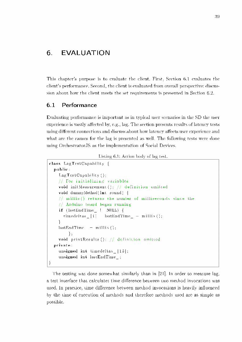
39
6. EVALUATION
This chapter's purpose is to evaluate the client. First, Section 6.1 evaluates the
client's performance. Second, the client is evaluated from overall perspective: discus-
sion about how the client meets the set requirements is presented in Section 6.2.
6.1 Performance
Evaluating performance is important as in typical user scenarios in the SD the user
experience is vastly a�ected by, e.g., lag. The section presents results of latency tests
using di�erent connections and discuss about how latency a�ects user experience and
what are the causes for the lag is presented as well. The following tests were done
using OrchestratorJS as the implementation of Social Devices.
Listing 6.1: Action body of lag test.
class LagTestCapabi l i ty {
public :
LagTestCapabi l i ty ( ) ;
// For i n i t i a l i z i n g v a r i a b l e s
void initMeasurement ( ) ; // d e f i n i t i o n omitted
void dummyMethod( int round ) {
// m i l l i s ( ) r e tu rn s the number o f m i l l i s e c ond s s i n c e the
// Arduino board began running
i f ( lastEndTime_ != NULL) {
t imedeltas_ [ i ] = lastEndTime_ − m i l l i s ( ) ;
}
lastEndTime_ = m i l l i s ( ) ;
} ;
void pr i n tRe su l t s ( ) ; // d e f i n i t i o n omitted
private :
unsigned int t imedeltas_ [ 1 5 ] ;
unsigned int lastEndTime_ ;
}
The testing was done somewhat similarly than in [21]. In order to measure lag,
a test interface that calculates time di�erence between two method invocations was
used. In practice, time di�erence between method invocations is heavily in�uenced
by the time of execution of methods and therefore methods used are as simple as
possible.

6. Evaluation 40
Test interface used for lag test is presented in Listing 6.1 as a C++ class. Test
interface consists of method initMeasurement() which initializes the needed variables
and dummyMethod(int round) which calculates time deltas between invocations and
stores them in a table. The method dummyMethod(int round) was invoked 16 times
in a row resulting in 15 time delta values. The method printResults() was used to
print all the values at once through serial port.
Taulukko 6.1: Communication latency between the client and the server using di�erentconnections. In the case of 3G and 4G, the test results include the latency to the router.
∆ti WLAN (ms) 4G (+ WLAN) (ms) 3G (+ WLAN) (ms)
1 2028 2059 2310
2 2031 2055 2285
3 2036 2060 2292
4 2026 2061 2341
5 2034 2056 2311
6 2039 2058 2309
7 2032 2060 2315
8 2029 2058 2286
9 2031 2057 2290
10 2037 2059 2303
11 2027 2062 2295
12 2029 2054 2290
13 2030 2053 2302
14 2031 2058 2289
15 2033 2055 2337
∆t 2032 2058 2304
σ 3.7 2.6 17.4
Results are presented in Table 6.1. In addition to time deltas, average and mean
values are calculated as well. WLAN measurements were done using high quality
Internet connection provided by Finnish University and Research Network (Funet).
In measurements for 3G and 4G, connections were provided by Finnish network
provider Saunalahti. During testing server side components were located in Ireland
on Amazon servers meaning "base latency"was around 70-80 milliseconds.
Latency is roughly around two seconds for each connection type. Latency mainly
consists of time that it takes the Arduino to handle the method invoking and sending
the response. Noteworthy is that the standard deviation of the latencies using WLAN
and 4G is quite low. Latency with 3G on the other hand, is much more unsteady
due to its technology. In comparison to [21] where similar latency test was made,

6. Evaluation 41
a modern mobile phone performed roughly 20 times faster. Interesting observation
was that the standard deviations were clearly higher in [21] than values seen in this
test. One of the reasons might be related to the mobile phone used in [21]: mobile
phone uses OS that supports parallel execution using threads which can result in
nondeterministic behaviour. Arduino in turn, o�ers more deterministic processing.
Miller [22] has categorized system's responsing times followingly from user expe-
rience perspective:
1. 0.1 seconds is about the time limit for having the user feel that the system is
reacting instantaneously.
2. 1.0 second is about the time limit for the user's �ow of thought to stay unin-
terrupted.
3. 10 seconds is about the time limit for keeping the user's attention focused on
the dialogue. For longer delays, users will want to perform other tasks while
waiting on the computer to �nish.
When compared to Miller's guideline, our system does not respond fast enough to
make end-users feel like the system responds instantaneously. When coordination is
done over cloud service, like in this case, it will be impossible to make the system
react in 0.1 second due to base latency. 1.0 second mark on the other hand, might
be reachable if certain optimizations were done. Last stage, 10 seconds, is ful�lled
rather easily: even if methods used are more complexed and computing intensive,
they will most likely be handled under 10 seconds. Miller does not discuss about how
stable responsive time re�ects to user experience but as we have seen, response times
are rather stable which makes the behaviour more predictable resulting perhaps in
better user experience.
Sources for the latency were investigated as well. It turned out that only minor
part (~150ms) of the latency was caused by the execution of the programming
code itself. It makes sense as the programming code does not include any intensive
calculating and the amount of slow memory operations (RAM) is relatively low.
The only major component for the lag seemed to be related to the WiFi Shield. The
execution of the program code part where the client asks (method WiFi.available(),
see Section 4.3) the WiFi Shield if the server has responded or not, was clearly the
most time consuming. Typically waiting time was around 1.5 seconds, although this
time period includes base latency and the time that it takes the server to handle the
client's response and send a new invocation.

6. Evaluation 42
6.2 Overall evaluation
The SD client is required to communicate with the server. In practice this means
that the client needs to register itself and be able to respond to requests from the
server. As we have seen, our client ful�ls these requirements mostly: the client is able
to register itself and responds to the requests. However, we might face a situation
where the client is processing previous request and can not respond. Additionally,
while scanning nearby devices the client can not respond either but this can be easily
solved as continuous scanning is not necessarily needed.
One of the necessities for a SD client was updating state values to the server
as well. Currently the client is capable of updating and posting its state values. In
reality, the client implementation has a component to update state values to the
server and a developer needs to add his own functionality to add desired states and
keep them updated (internally).
As said, the client is expected to send RSSI values to the server to keep the
proximity graph up to date. In our client implementation we added a functionality
that serves this purpose. However, without proper hardware abstraction layer the
implementation is only compatible with speci�c Bluetooth module.
Finally, we are safe to say that the client can act as Social Devices client or atleast
is a proof of concept.
43
7. CONCLUSION
As a part of this Master's Thesis a Social Devices client was developed for Arduino
platform. The client ful�ls the necessary requirements to act as Social Devices client.
The client also functions as a proof of concept for Social Devices. A modest device,
such as Arduino, is capable of functioning as a part of Social Devices and provides
an ideal platform for developers to design certain applications for Social Devices
that are not possible with more traditional devices like mobile phones for example.
In addition, our client was an example how diverse the devices in Social Devices
can be: Social Devices' implementations function as an abstraction layer for all
di�erent devices. As a future work we discussed about improving the performance:
we might face situations where the client can not respond to requests from the
server and this may lead to problems. This could be solved with a thread-supporting
OS. Additionally, performance-wise we concluded that the performance of the client
satis�es the needs of most applications. However, in applications that require real-
time responsiveness, our client does not function fast enough and this might result
in hindered user-experience, for instance.
The secondary purpose was to implement the client a way that a developer can
easily attach his own program code modules that would include the implementations
of functionality that can be used for application in the system. To serve this purpose,
a hardware abstraction layer was implemented. In practice, a developer can edit a
con�guration �le that holds information which interface implementations the build
will include. In addition, the con�guration �le also helps setting up an embedded
system since it is easier to see which resources are currently in use. Finally, adding
own programming code is rather simple as you need include your own if -block in a
certain source �le.
In the literature review part Social Devices concept was introduced. Social De-
vices presents a new kind of sociodigital system where humans and devices both par-
ticipate in. We also presented two implementations for Social Devices and became
familiar with their architecture and components. Both implementations, the Social
Devices Platform and OrchestratorJS, try to �ll the requirements for Social Devices
in practice. For instance, the implementations take care of keeping track of the close-
ness of the devices and �nd a suitable con�guration for devices that are near of each
other. Additionally, the implementations orchestrate operation execution between
7. Conclusion 44
the devices.
During the development of the client we faced many typical challenges regarding
developing software for an embedded system. Rather modest resources, such as RAM
memory, lead to a di�erent set of problems: issues like fragmentation and the lack
of memory had to be taken into account when designing the software. Matters like
these were good examples of challenges that are related to developing software for
embedded systems. Therefore, we can agree that implementing the client provided
valuable insight, which was also one of the thesis' purposes.
45
REFERENCES
[1] Phonearena [WWW]. [referenced: 11.9.2014]. Available:
http://www.phonearena.com/news/A-modern-smartphone-or-a-vintage-
supercomputer-which-is-more-powerful_id57149
[2] N. Mäkitalo, J. Pääkkö, M. Raatikainen, V. Myllarniemi, T. Aaltonen, T.
Leppanen, T. Mannisto, and T. Mikkonen. Social Devices: collaborative co-
located interactions in a mobile cloud. In International Conference on Mobile
and Ubiquitous Multimedia. ACM, 2012.
[3] T. Aaltonen, V. Myllärniemi, M. Raatikainen, N. Mäkitalo, J. Pääkkö, An
Action-Oriented Programming Model for Pervasive Computing in a Device
Cloud. In Proceedings of APSEC'2013, 2013.
[4] P. Simons, I. Niemelä, and T. Soininen. Extending and implementing the stable
model semantics. Arti�cial Intelligence, 138(1?2):181?234, June 2002.
[5] N. Mäkitalo, "Building and Programming Ubiquitous Social Devices". ACM,
2014.
[6] M. Satyanarayanan. Pervasive computing: Vision and challenges. IEEE Perso-
nal communications, 8(4):10?17, Aug. 2001.
[7] M. Papazoglou. Extending the service-oriented architecture. Business Integra-
tion Journal, 7(1):18?21, Feb. 2005.
[8] Wikipedia [WWW]. [referenced: 13.7.2014]. Available:
http://en.wikipedia.org/wiki/OSI_model
[9] Postel, J., "Transmission Control Protocol", STD 7, RFC 793, September 1981.
[10] Fielding, R., Gettys, J., Mogul, J., Frystyk, H., and T. Berners-Lee, "Hypertext
Transfer Protocol � HTTP/1.1", RFC 2068, January 1997.
[11] Wikipedia [WWW]. [referenced: 10.11.2014]. Available:
http://en.wikipedia.org/wiki/Comet_(programming)
[12] Fette, I. and A. Melnikov, "The WebSocket Protocol", RFC 6455, December
2011.
[13] Guillermo Rauch, Socket IO, (2012), GitHub repository,
https://github.com/LearnBoost/socket.io-spec .
REFERENCES 46
[14] Arduino - open-source electronis prototyping platform [WWW]. [accessed on
15.1.2014]. Available at: http://arduino.cc/ .
[15] Roving Networks, "RN-42 Class 2 Bluetooth Module"DS-RN42-V1.0 datasheet,
12/6/2010.
[16] Adrian McEwen, HTTP client for Arduino, (2013), GitHub repository,
https://github.com/amcewen/HttpClient .
[17] Bill Roy, SocketIO client for Arduino, (2013), GitHub repository,
https://github.com/billroy/socket.io-arduino-client.
[18] Järvinen, H-M. Mikkonen, T., Sulautettu Ohjelmointi, 1. edition. Tampere,
Kopio Niini Oy, 2012. 206 s.
[19] Benoit Blanchon, Arduino JSON library, (2014), GitHub repository,
https://github.com/bblanchon/ArduinoJson .
[20] Wikipedia [WWW]. [referenced: 13.7.2014]. Available:
http://en.wikipedia.org/wiki/Servomotor .
[21] N. Mäkitalo, T. Mikkonen , "At the Edge of the Cloud: Improving the Coordi-
nation of Proactive Social Devices". AIS, 2014.
[22] R., Miller, Response time in man-computer conversational transactions, Proc.
AFIPS Spring Joint Computer Conference Vol 33, 267-277, 1968.