Embed Size (px)
Citation preview
SENSE SNS 200
Ver. 2016-12-10
OPERATING MANUAL
Locating system for horizontal
directional drilling
SNS 200
Technical support, warranty, training and sales:
MARPOL Trenchless Technology 05-830 Nadarzyn
Stara Wies, Grodziska 7, Warsaw, Poland
www.marpol.com.pl
tel. +48506160094, +48227983490, [email protected]
SENSE SNS 200
Operating manual ofSNS 200 locating system
3
The present manual is meant for reviewing the safety instructions, standard operating procedures, box contents and the configuration of the locating system for horizontal directional drilling – SNS 200 (system SNS 200).
The operating manual for SNS 200 system is the main document for training the operating staff who execute the work of horizontal directional drilling in accordance with the specified project with the use of SNS 200 locating system.
The technical information and recommendations outlined in the present manual fully comply with the current modification of SNS 200 system and its software version and apply neither to any other current modifications of the system configurations and its software implemented by the operator without any relevant approval of LLC SENSE nor to any work-piece executed by the third party.
None of the provisions of the present document constitute to the warranty obligations of LLC SENSE and cannot be regarded as the conditions for altering the terms of the existing limited warranty of LLC SENSE which applies to all the products of the company.
SENSE SNS 200
Operating manual ofSNS 200 locating system
4
Contents
CONTENTS 4
ABOUT COMPANY 5
ОБРАЩЕНИЕ КЗАКАЗЧИКУ 5
SAFETY INSTRUCTIONS 6
INTRODUCTION 8
RECEIVER 9
CORRECT USE 9
TECHNICAL SPECIFICATIONS 9
Setting a set of batteries 11
Main menu 11
Calibration 15
‘Location’ mode 16
Sondes 18
Technical specifications 18
Batteries(switch on/off the sonde power) 19
Requirements to the head drill case 20
Information about sonde condition 21
DRILL MASTER’S CONTROL 22
General description 22
Power supply 23
Main menu of the drill master’s control 24
TRANSMITTER 26
General description 26
Technical specifications 26
WARNINGS AND CAUSIONS 28
LOCATION 29
General description 29
Correct use 29
Interference–description and ways of avoidance 31
Allowance evaluation of the sonde inclination`s angle 32
PROGRAM PACK SNS 200 34
Software and driver COM-USB installation 34
Summary 35
1. Preparation for work 35
1.1Preparing the receiver for work with the program 35
1.2Preparating program for work with the receiver 38
2. Uploading tables of protocols from the receiver, their editing and saving tables into the file 41
2.1Editing tables 42
2.2Saving tables into file 43
OPERATING AND SERVICE PROCEDURES 45

SENSE SNS 200
Operating manual ofSNS 200 locating system
5
About company
LLC SENSE company has been developing and producing locating systems for horizontal directional drilling (HDD) since 1994. Creative approach at all the stages of production process, thorough choice of and careful attention to the demand of the HDD technology - these are base principles of the company’s work. Nowadays LLC SENSE has rich experience of cooperation with leading foreign producers and national operators of locating systems and its components. The present experience together with creativity and personnel potential of competent professionals ensures a high competitiveness for the company’s products in comparison with foreign counterparts for the best value for money.
Addressing the cusomer
Dear user, We would like to thank you for the fact that you have chosen our SNS 200 locating system. We are very proud of our equipment and hope that you will fully evaluate its advantages. Our main company mission is the creation of the unique highly qualified equipment and e\relevant service support from the customer service department, also training the staff to work with the equipment. If any questions arise you are always welcome to contact our representatives by one of the phone numbers stated on the front page of the present manual. We attentively take care of all scientific developments in the sphere of horizontal directional drilling with the purpose of creating new equipment which can assist in speeding and making the work easier.you can follow the new by yourselves on our website: www.sense- inc.ru or by calling us. We are always ready to respond to all your questions and hear your remarks and suggestions.
SENSE SNS 200
Operating manual ofSNS 200 locating system
6
Safety instructions
Reviewing the safety instructions is obligatory for the staff of the drilling rig and following them guarantee avoidance of injuries and brackage of high-priced equipment and surrounding objects.
1. Avoid the contact of the underground drilling equipment with underground utilities, HV or gas pipelines. 2. The operators of the horizontal directional drilling shall meet the following requirements: • know the methods of safe and proper service of drilling and steering equipment including using insulating mats and relevant methods of equipment grounding; • before the start of drilling make sure that all the underground utilities and communication networks are allocated, identified and correctly specified; • use the relevant uniform – helmet and contrasting jackets; • precisely and correctly do the locating and following the sondes which were installed in the boring head while drilling; • meet the requirements of national and local governmental regulations; • fulfill all the other corporate requirements of the safety instructions. 3. SNS 200 steering system can’t be used for localizing utilities. 4. The continuous use in conditions of high temperatures which are caused by the heating of the boring head is unacceptable. 5. Steering equipment mustn’t be operated near highly flammable and explosive materials. 6. In case of long distance transporting or long-term storage the batteries must be taken out from all the nodes of the system.
7. Before every drilling session in case of the precise and correct installation of the sonde it is necessary to do the calibration of SNS 200 system in order to prove its correct work and passing precise information in respect of the location and guidance of the drill head.
SENSE SNS 200
Operating manual ofSNS 200 locating system
7
8. To obtain accurate readings about the depth of the drill head while boring the main requirement shall be met: the receiver should be positioned above the sonde, installed under the drill head underground.
9. After any breaks in the process of drilling calibration check of the equipment shall be
performed every time.
10. To avoid obtaining inaccurate parametres or loss of information about the sonde location it is necessary to do the check-up if there is electromagnetic interference:
traffic signal loops, inconspicious dog fences, cathodic protection, radio communication devices, high frequency installations, TV cables, digital utility networks, security systems, telephone cables, conductive earth, telephone cables, salty water, HF radiation and other interference sources;
interference sources in case of the use of the repeater can be other sources of radiation working on the same frequency near the display (E.g. system of distant car registering of other locating equipment of HDD));
On performing any location operations the interference level should be minimal.
SENSE SNS 200
Operating manual ofSNS 200 locating system
8
Introduction
SNS 200 locating system is used in the process of horizontal directional drilling for spotting the location of the sonde installed under the drill head underground. The system consists of the receiver, sonde, drill master’s control (repeater) with cable and battery supply, the transmitter, set of batteries and antennae for all the devices of the system, USB-radiomodem for the computer and software of the system.
SNS 200locating system can be equipped by several sondes of various use, depth and usage period. The standard pack includes a wireless sonde – transmitter with the fixed depth of 15 m. The pack can be additionally equipped with other sondes for the depth of 20,25 and 30 m (wire sonde). SNS 200 locating system has a function of recording pieces of data of boring while sinking. Boring data can be uploaded on the computer with the software program that goes with the system.
The present manual has information about each component of the SNS 200 system: the receiver, the control, the sonde, the transmitter and the software. In the following chapters there is a description of the preparing the components of the system before drilling and its proper use while drilling
.
SENSE SNS 200
Operating manual ofSNS 200 locating system
9
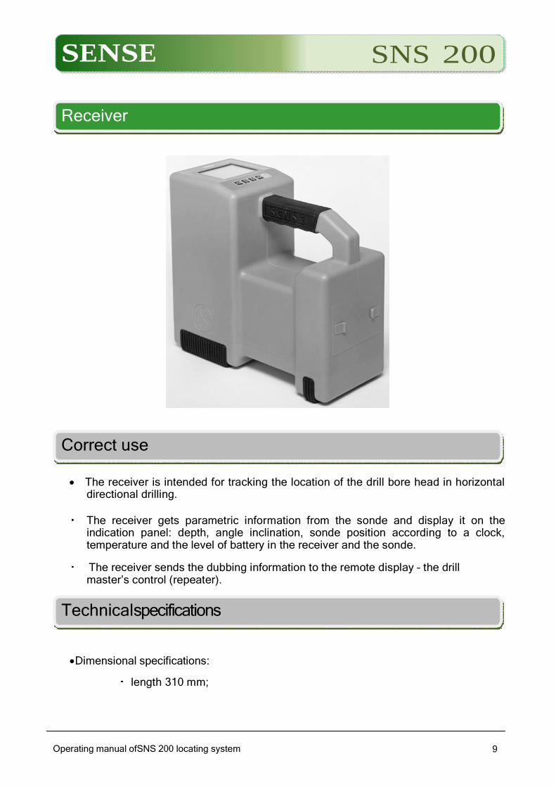
Receiver
Correct use
The receiver is intended for tracking the location of the drill bore head in horizontal directional drilling.
The receiver gets parametric information from the sonde and display it on the
indication panel: depth, angle inclination, sonde position according to a clock, temperature and the level of battery in the receiver and the sonde.
The receiver sends the dubbing information to the remote display – the drill master’s control (repeater).
Technicalspecifications
Dimensional specifications:
length 310 mm;

SENSE SNS 200
Operating manual ofSNS 200 1010
width140mm;
height 285mm.
Net weight:not more than4kg. Power supply:6batteries LR14 type,size С,orNiMHaccumulators of the same size,
capacity– not less than 4500 мА*hour.
Duration of the constant work from one battery set –more than 10hours.
Information indication:graphic LCD monitor.
Menu in Russian. Possibility to enter and save the current information in the process of drilling and
making a drilling route. The distance of the radio coverage to the drill master’s control (in direct visibility), not
less than:
0m without transmitter;
0 m with one transmitter. If several transmitters are used the distance is getting bigger in proportion to their quantity at increment of 500m.
Range of working temperatures: from − 20 up to relative humidity up to
98 %.
SENSE SNS 200
Operating manual ofSNS 200 1111
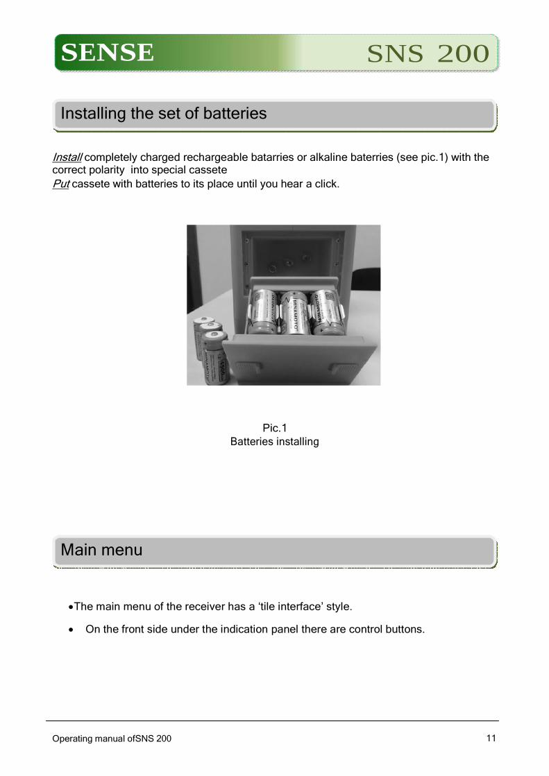
Installing the set of batteries
Install completely charged rechargeable batarries or alkaline baterries (see pic.1) with the correct polarity into special cassete
Put cassete with batteries to its place until you hear a click.
Pic.1
Batteries installing
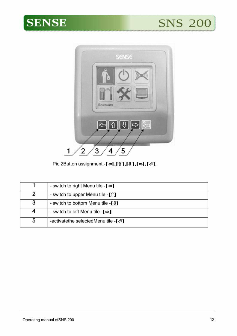
Main menu
The main menu of the receiver has a ‘tile interface’ style.
On the front side under the indication panel there are control buttons.
SENSE SNS 200
Operating manual ofSNS 200 1212
Pic.2Button assignment:-[⇦],[⇧],[⇩],[⇨],[⏎].
1 – switch to right Menu tile -[⇦]
2 – switch to upper Menu tile -[⇧]
3 – switch to bottom Menu tile -[⇩]
4 – switch to left Menu tile -[⇨]
5 -activatethe selectedMenu tile -[⏎]
SENSE SNS 200
Operating manual ofSNS 200 1313
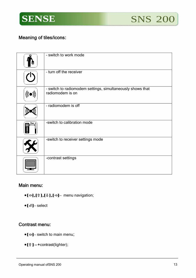
Meaning of tiles/icons:
– switch to work mode
– turn off the receiver
– switch to radiomodem settings, simultaneously shows that radiomodem is on
– radiomodem is off
-switch to calibration mode
-switch to receiver settings mode
-contrast settings
Main menu:
[⇦],[⇧],[⇩],[⇨]– menu navigation;
[⏎]– select
Contrast menu:
[⇦]– switch to main menu;
[⇧]-+contrast(lighter);
SENSE SNS 200
Operating manual ofSNS 200 1414
[⇩]- contrast(darker);
[⇨]-switch to main menu
Location:
[⇦]– exit the menu;
[⇧]– Точ/Сбр.– Updating the depth readings.Сбр.– cancel updating mode.
Updating is used only in motionless position of the receiver and the sondes.
[⇩]– Зам.– measure– measuring the angle nd the depth for the current drill bar
in a protocol table.(Protocol table shall be made in advance)
[⇨]– RLF–manual setting the location zone of the receiver regarding the sondes:-
R–in front of sonde,L–above sonde,F –behind zonde
[⏎]– exit the menu
Менюнастройкирадиомодема:
[⇧],[⇩],[⏎]-select the radio channel(0,1,2,3)
[⇧],[⇩],[⏎]-select the commumication– without transmitter, with one or
two transmitter, switch off the modem
Settings Menu:
Current drilling bar number:-[⇧],[⇩],[⏎]– set up;
Managing protocol tables:-[⏎]– select;
Select units of display of the sonde’s angle inclination (℃,%):-[⇧],[⇩],[⏎]–
set up;
Select angle displacement of the sonde’s rotation(clock):-[⇧],[⇩],[⏎]–
set up;
Select allowances for displaying the receiver’s depth-height: - [⇧] ,
[⇩],[⏎]– set up
SENSE SNS 200
Operating manual ofSNS 200 1515
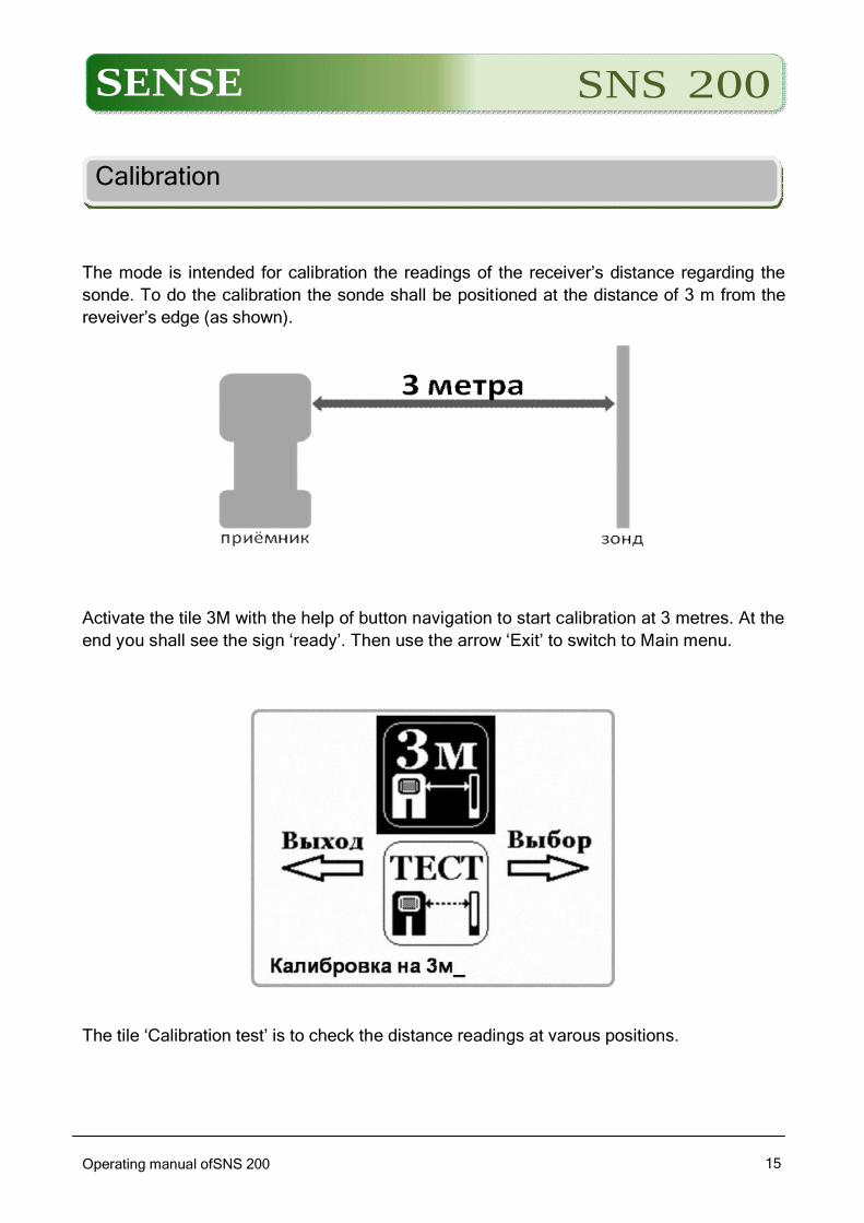
Calibration
The mode is intended for calibration the readings of the receiver’s distance regarding the
sonde. To do the calibration the sonde shall be positioned at the distance of 3 m from the
reveiver’s edge (as shown).
Activate the tile 3M with the help of button navigation to start calibration at 3 metres. At the
end you shall see the sign ‘ready’. Then use the arrow ‘Exit’ to switch to Main menu.
The tile ‘Calibration test’ is to check the distance readings at varous positions.
SENSE SNS 200
Operating manual ofSNS 200 1616
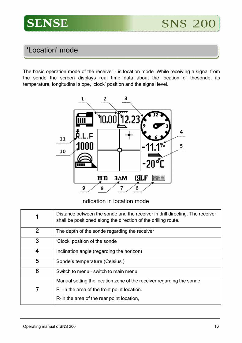
‘Location’ mode
The basic operation mode of the receiver - is location mode. While receiving a signal from
the sonde the screen displays real time data about the location of thesonde, its
temperature, longitudinal slope, ‘clock’ position and the signal level.
Indication in location mode
1 Distance between the sonde and the receiver in drill directing. The receiver
shall be positioned along the direction of the drilling route.
2 The depth of the sonde regarding the receiver
3 ‘Clock’ position of the sonde
4 Inclination angle (regarding the horizon)
5 Sonde’s temperature (Celsius )
6 Switch to menu – switch to main menu
7
Manual setting the location zone of the receiver regarding the sonde
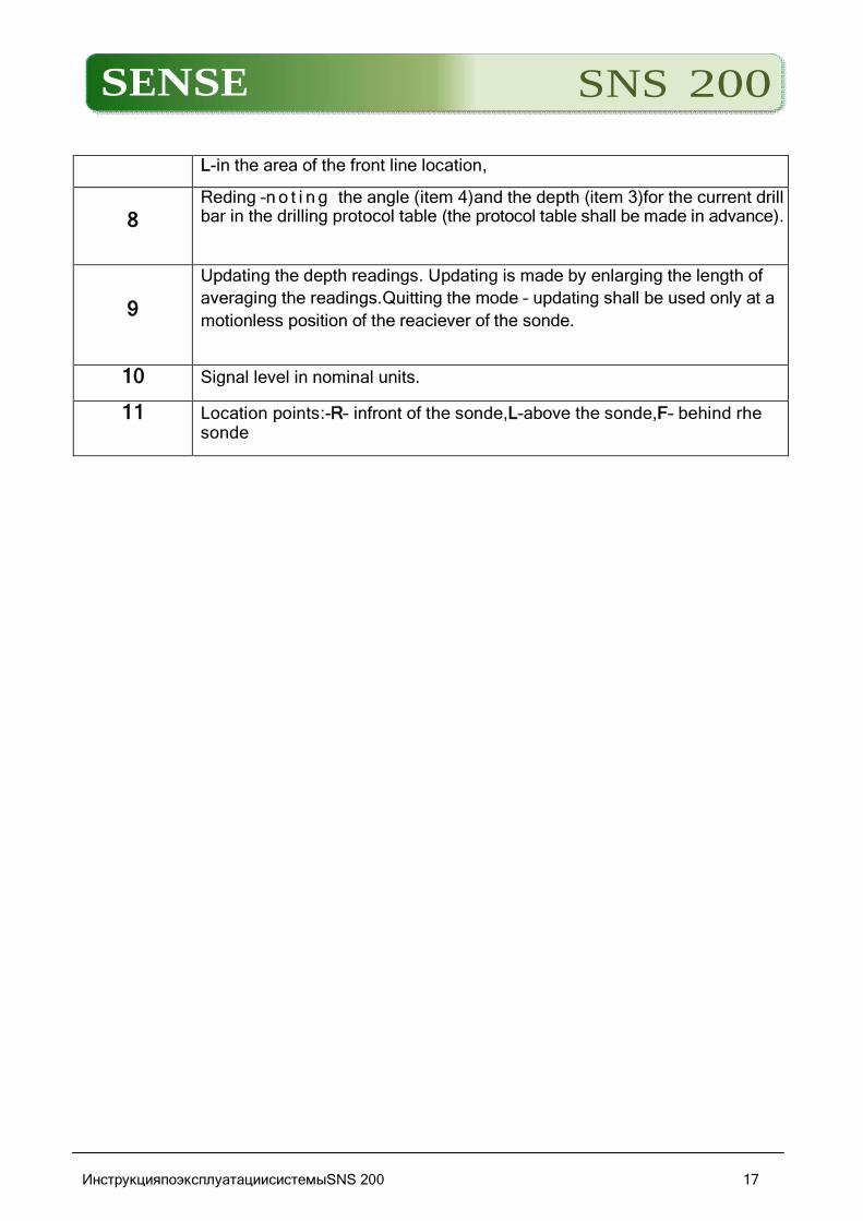
F – in the area of the front point location.
R-in the area of the rear point location,
SENSE SNS 200
L-in the area of the front line location,
8 Reding –n o t i n g the angle (item 4)and the depth (item 3)for the current drill bar in the drilling protocol table (the protocol table shall be made in advance).
9
Updating the depth readings. Updating is made by enlarging the length of
averaging the readings.Quitting the mode – updating shall be used only at a
motionless position of the reaciever of the sonde.
10 Signal level in nominal units.
11 Location points:-R– infront of the sonde,L–above the sonde,F– behind rhe sonde
ИнструкцияпоэксплуатациисистемыSNS 200 17
SENSE SNS 200
Operating manual of SNS 200 system
1818
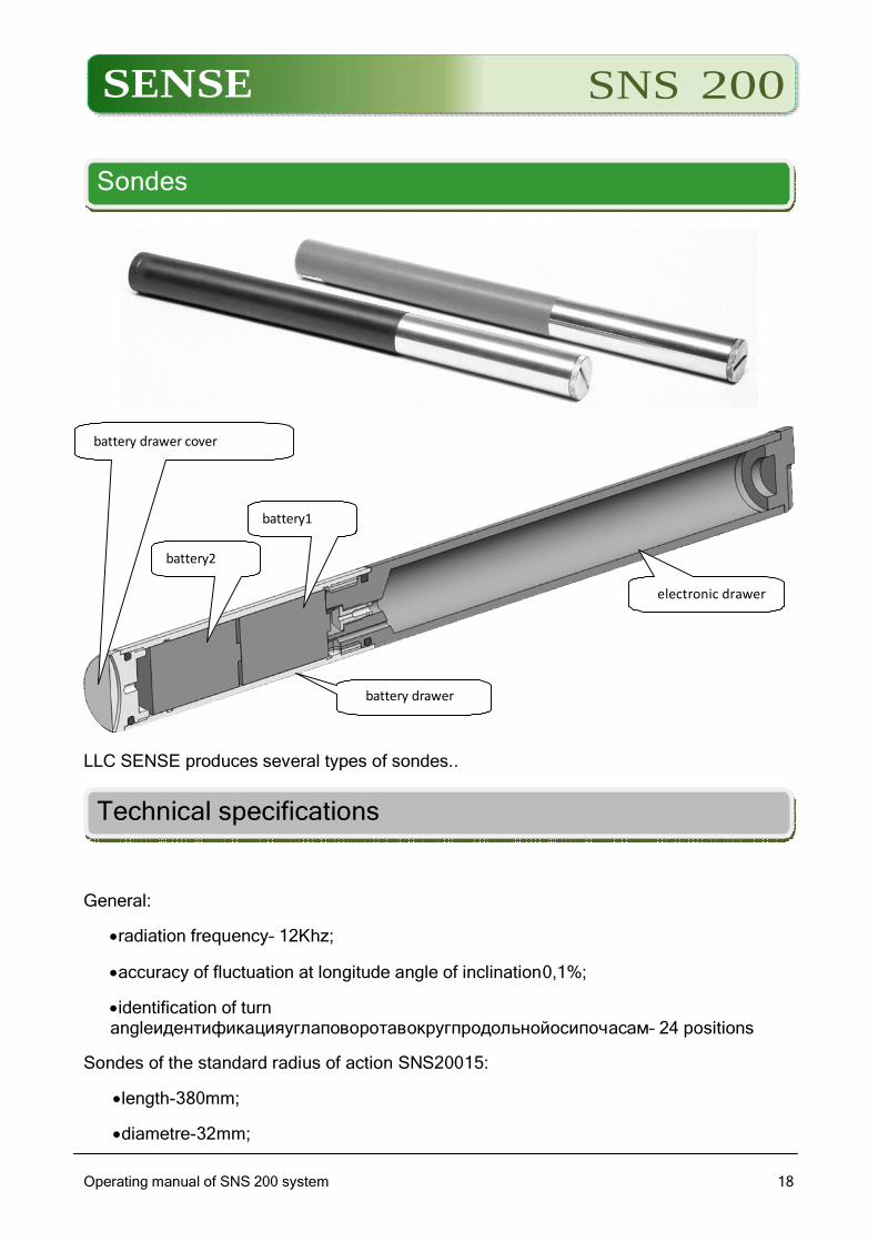
Sondes
battery drawer cover
battery1
battery2
electronic drawer
battery drawer
LLC SENSE produces several types of sondes..
Technical specifications
General:
radiation frequency– 12Khz;
accuracy of fluctuation at longitude angle of inclination0,1%;
identification of turn angleидентификацияуглаповоротавокругпродольнойосипочасам– 24 positions
Sondes of the standard radius of action SNS20015:
length-380mm;
diametre-32mm;
SENSE SNS 200
Operating manual of SNS 200 system
1919
operational depth-up to 15 metres.
Sondes of wide coverage SNS20020,30:
length-480mm;
diametre -32mm;
operational depth– from20 m up to30m.
Operational range of any sonde used with the reciever SNS300 mainly depends
on the background interference range at drilling site.The operational range of
the sonde reduces as the enterference range rising.
Batteries (on/off the sonde power)
For a standard range (PRO 15) sonde’s operation two working alkaline batteries C or one
lithium battery (SuperCell USA) are required. When working with long-range sonde (PRO
25) it is highly recommended to use only lithium (alkaline batteries work only for a few
hours).
It is forbidden to use damaged lithium batteries or lithium batteries manufactured by other
companies. Use of damaged or poor-quality lithium batteries may damage the sonde and /
or the case and will invalidate the warranty of the manufacturer.
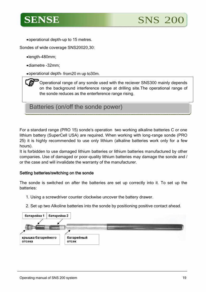
Setting batteries/switching on the sonde
The sonde is switched on after the batteries are set up correctly into it. To set up the
batteries:
1. Using a screwdriver counter clockwise uncover the battery drawer.
2. Set up two Alkoline batteries into the sonde by positioning positive contact ahead.
SENSE SNS 200
Operating manual ofSNS 200 system
2020
Check the signal of the sonde with the help of the relevant receiver.
Charge level of the sonde’s batteries
When using alkaline batteries their level of charge is shown at the bottom right part of the
screen in locating receiver mode. In the case of using with sondes 15 PRO or PRO lithium
battery 25, a charge indication will remain at the maximum level until they discharge
completely.
As the charge level indication will remain at the maximum level until the
complete discharge you shall carry out the registration of the operational period
of the sonde with the lithium battery.
Standby mode (automatic switch off/switch off the sonde)
In order to save battery power, the sondes PRO 15 and PRO 25 automatically switch to
standby mode and stop sending a signal if they are in a motionless position for more than
15 minutes. In order to bring the sonde from the standby mode, you simply rotate the drill
head.
In standby mode, the sonde continues to consume a small amount of battery power. To
prevent battery discharge, do not leave batteries in the transmitter when they can be easily
removed from it, and make sure to remove the batteries if you do not intend to use the
sonde.
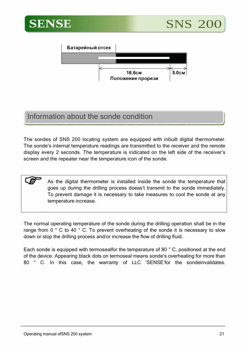
Requirements to the drill head case
To obtain the maximum range of the sonde’s action and extend the life span of the
batteries there shall be slots that meet the requirements for the minimum length, width,
and location on the case of the drill head. LLC ‘SENSE’ recommends having at least three
slots which have a width of at least 1.6 mm and are spaced evenly around the
circumference of the case. The size of the slot should always be measured at the inner
surface of the case.
SENSE SNS 200
Operating manual ofSNS 200 system
2121
Information about the sonde condition
The sondes of SNS 200 locating system are equipped with inbuilt digital thermometer.
The sonde’s internal temperature readings are transmitted to the receiver and the remote
display every 2 seconds. The temperature is indicated on the left side of the receiver’s
screen and the repeater near the temperature icon of the sonde.
As the digital thermometer is installed inside the sonde the temperature that
goes up during the drilling process doeas’t transmit to the sonde immediately.
To prevent damage it is necessary to take measures to cool the sonde at any
temperature increase.
The normal operating temperature of the sonde during the drilling operation shall be in the
range from 0 ° C to 40 ° C. To prevent overheating of the sonde it is necessary to slow
down or stop the drilling process and/or increase the flow of drilling fluid.
Each sonde is equipped with termosealfor the temperature of 80 ° C, positioned at the end
of the device. Appearing black dots on termoseal means sonde’s overheating for more than
80 ° C. In this case, the warranty of LLC ‘SENSE’for the sondeinvalidates.
SENSE SNS 200
Operating manual ofSNS 200 system
2222
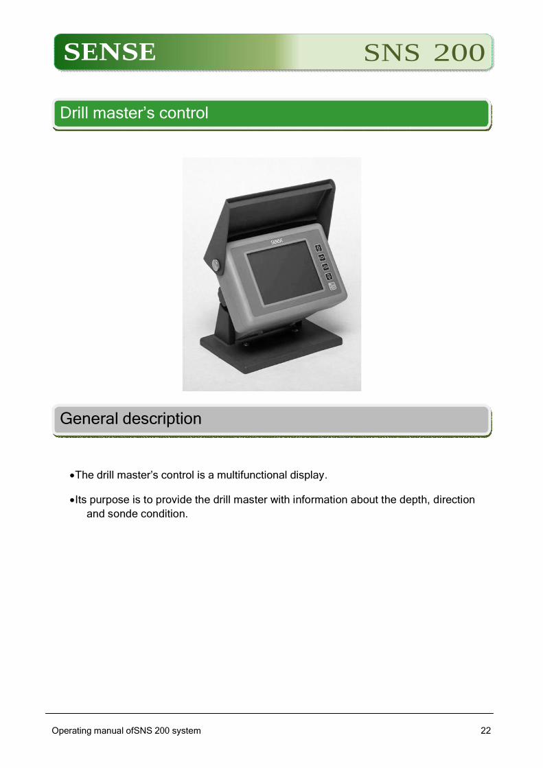
Drill master’s control
General description
The drill master’s control is a multifunctional display.
Its purpose is to provide the drill master with information about the depth, direction
and sonde condition.
SENSE SNS 200
Operating manual ofSNS 200 system
2323
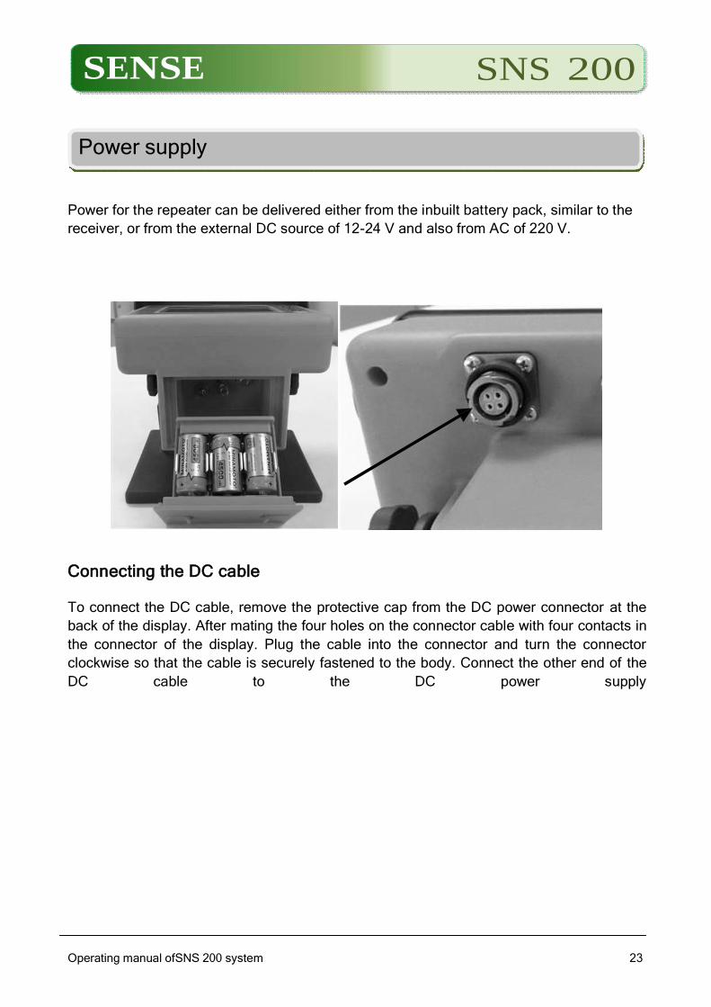
Power supply
Power for the repeater can be delivered either from the inbuilt battery pack, similar to the
receiver, or from the external DC source of 12-24 V and also from AC of 220 V.
Connecting the DC cable
To connect the DC cable, remove the protective cap from the DC power connector at the
back of the display. After mating the four holes on the connector cable with four contacts in
the connector of the display. Plug the cable into the connector and turn the connector
clockwise so that the cable is securely fastened to the body. Connect the other end of the
DC cable to the DC power supply

SENSE SNS 200
Operating manual ofSNS 200 system
2424
Main menu of the drill master’s control
1 – switch to upper tile menu
2 – switch to right tile menu
3 – switch to left tile menu
4 – switch to low tile menu
5 -activate the chosen tile of menu
The meaning of icons/tiles:
– switch to work mode
– turn off the receiver

SENSE SNS 200
– switch to radiomodem settings menu
-contrast settings
-switch to wiresonde work mode
Operating manual ofSNS 200 system
25
SENSE SNS 200
Operating manual ofSNS 200 locating system
2626
Transmitter
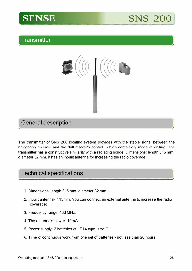
General description
The transmitter of SNS 200 locating system provides with the stable signal between the
navigation receiver and the drill master’s control in high complexity mode of drilling. The
transmitter has a constructive similarity with a radiating sonde. Dimensions: length 315 mm,
diameter 32 mm. It has an inbuilt antenna for increasing the radio coverage.
Technical specifications
1. Dimensions: length 315 mm, diameter 32 mm;
2. Inbuilt antenna– 115mm. You can connect an external antenna to increase the radio
coverage;
3. Frequency range: 433 MHz;
4. The antenna’s power– 10mW;
5. Power supply: 2 batteries of LR14 type, size C;
6. Time of continuous work from one set of batteries - not less than 20 hours;
SENSE SNS 200
Operating manual ofSNS 200 locating system
2727
7. Indication: LED. Indicates the presence of datatransmission and the end of life of the
battery power.
Please note that the standard supply goes without a tripod. Tripod can be
ordered further if necessary
SENSE SNS 200
Operating manual ofSNS 200 locating system
2828
Warnings and Cautions
LLC ‘SENSE’ is not responsible for any problems that may used by any violation of these
warnings, as well as the general recommendations in Warnings and Cautions in Safety
Instructions chapter.
Warning: All the batteries for the system modules are designed with protection from shock
and other hazards in case the operation of this device is carried out in accordance with the
rules outlined in this manual. Violation of the operation rules for the batteries stated in this
document may result in deteriorating the level of protection provided. Before using the
battery, please, read the manual.
Warning: when transporting system modules it is highly recommended to remove the
batteries from the receiver, sonde and transmitter and disconnect the wires from the driller
master’s control to secureoperating performance both of the equipment and batteries.
SENSE SNS 200
Operating manual ofSNS 200 locating system
2929
Locating
General description
Locating with SNS200 system is not a difficult and preparation-consuming operation.
In the present chapter there is a description of the location points and location line, the
geometrical layout of these elements regarding the sonde that appear on the receiver’s
display while locating and relevant methods of marking location points after their
identification. After that the standard rules of locating are given including an ‘operational’
method of tracking and the method of tracking the sonde without access to the ground
surface above the sonde which is called ‘remote location’.
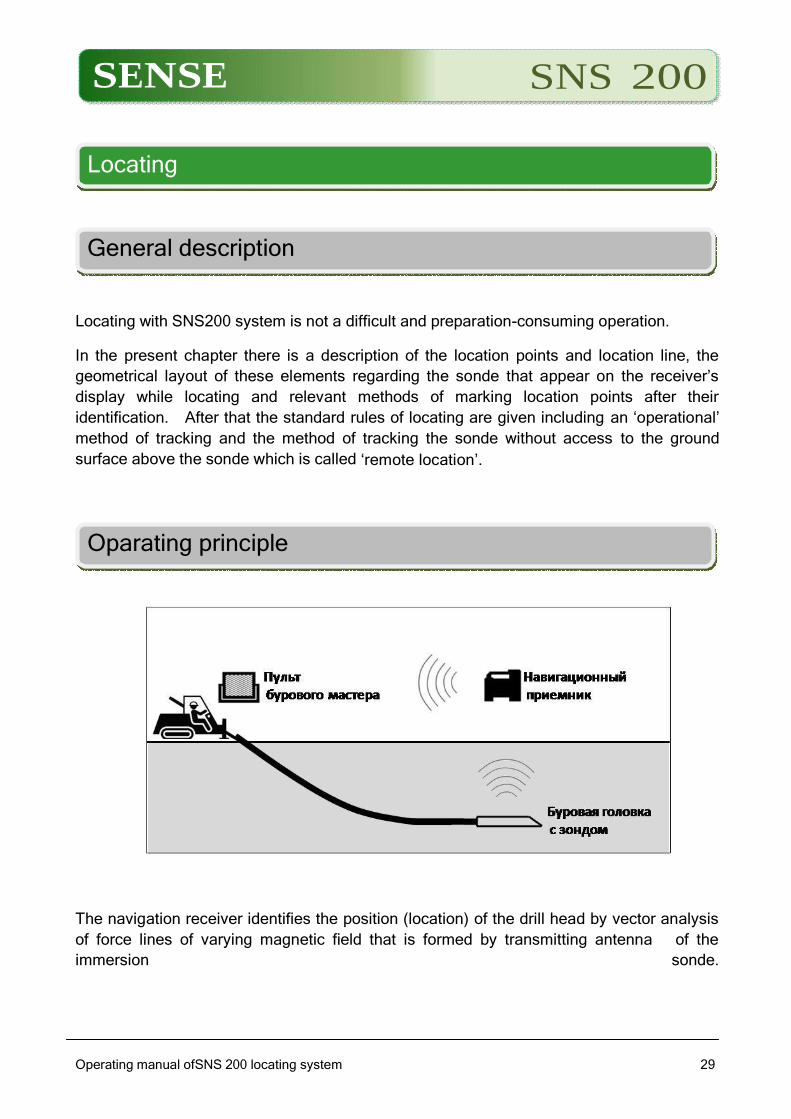
Oparating principle
The navigation receiver identifies the position (location) of the drill head by vector analysis
of force lines of varying magnetic field that is formed by transmitting antenna of the
immersion sonde.
SENSE SNS 200
Operating manual ofSNS 200 locating system
3030
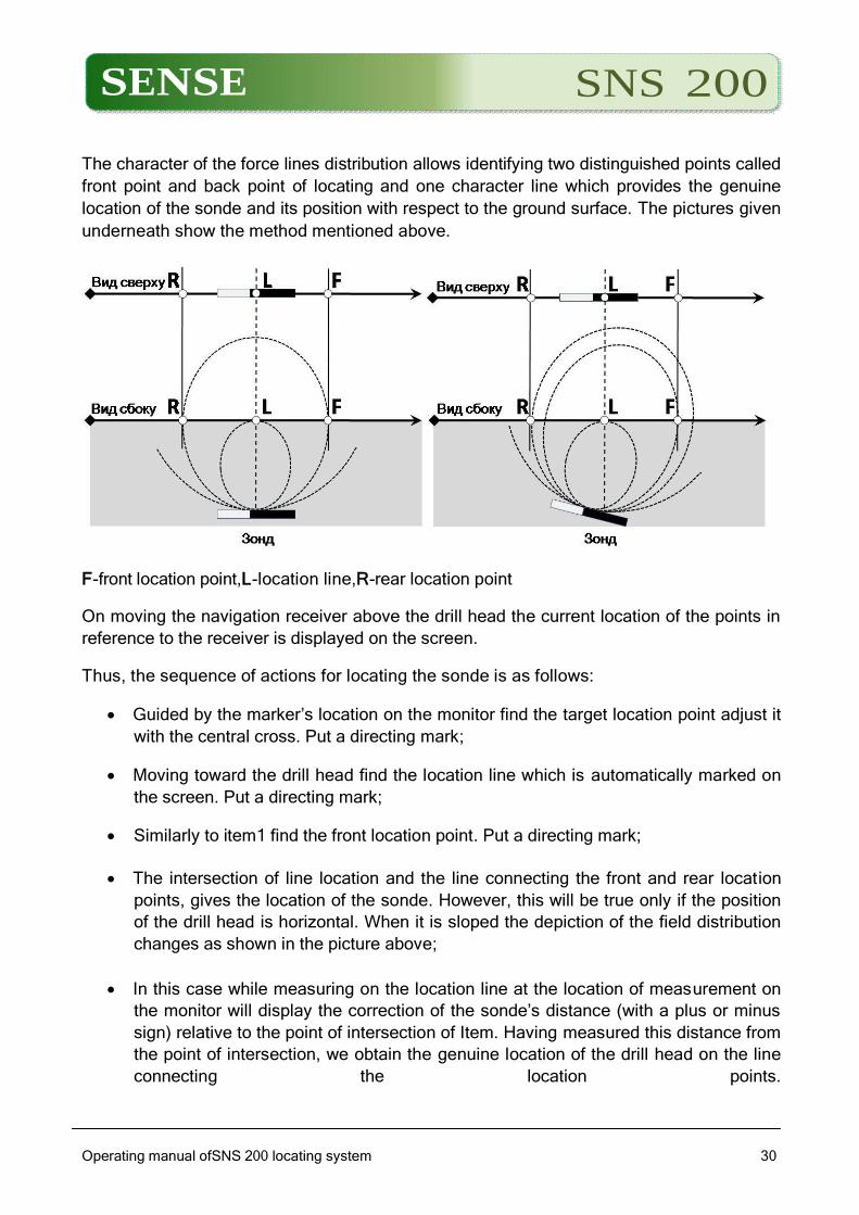
The character of the force lines distribution allows identifying two distinguished points called
front point and back point of locating and one character line which provides the genuine
location of the sonde and its position with respect to the ground surface. The pictures given
underneath show the method mentioned above.
F-front location point,L-location line,R-rear location point
On moving the navigation receiver above the drill head the current location of the points in
reference to the receiver is displayed on the screen.
Thus, the sequence of actions for locating the sonde is as follows:
Guided by the marker’s location on the monitor find the target location point adjust it
with the central cross. Put a directing mark;
Moving toward the drill head find the location line which is automatically marked on
the screen. Put a directing mark;
Similarly to item1 find the front location point. Put a directing mark;
The intersection of line location and the line connecting the front and rear location
points, gives the location of the sonde. However, this will be true only if the position
of the drill head is horizontal. When it is sloped the depiction of the field distribution
changes as shown in the picture above;
In this case while measuring on the location line at the location of measurement on
the monitor will display the correction of the sonde’s distance (with a plus or minus
sign) relative to the point of intersection of Item. Having measured this distance from
the point of intersection, we obtain the genuine location of the drill head on the line
connecting the location points.
SENSE SNS 200
Operating manual ofSNS 200 locating system
3131
Together with formation of varying magnetic field for determining the coordinates the sonde
passes the following information to the navigation receiver::
1. The inclination angle of the sonde in vertical plane;
2. The angle of turn to the longitudinal axis of rotation;
3. The sonde’s temperature;
4. Residual capacity of the power batteries.
The information is constantly displayed on the receiver’s screen and transmitted via the
radio to the drill master’s control.
Interference – description and ways of their withdrawal
Before drilling you need to evaluate the interference potential at the working site. Interference
can reduce the range of the sonde or result in inaccurate measurements and may cause
reduction in work dinamics. Interference comes from two different types of sources: active and
passive.
Active interference is also known as electromagnetic interference or background noise can
impact SNS 200 system and cause various effects. Most electric devices emit signals that
can affect the ability to accurately locate the sonde or to obtain qualified information about
the sonde slope. Some examples of active interference among others are traffic signal
loops, buried dog fences, cathodic protection, radio communication devices, high frequency
installations, TV cables, fiber optic cables, digital utility networks, security systems,
electrical cables, telephone cables.
Passive interference can reduce the quality of the signal from the sonde, resulting in a
greater than expected depth readings or a completely blockage of signal. Examples of
passive interference are metal objects (such as pipes, rebar, trench plate, metal fences or
cars). Two other examples of passive interference are salty water / salt domes and
conductive earth, such as iron ore. The best method of identifying passive interference
sources is a thorough site investigation prior to drilling.

SENSE SNS 200
Operating manual ofSNS 200 locating system
3232
SENSE SNS 200
Operating manual ofSNS 200 locating system
3333
The first step is to check the calculated direction for the presence of potential sources of
interference. The next step is to check for the presence of electromagnetic interference /
background noise.
Allowance evaluation of the sonde inclination`s angle
When routing communications requiring high accuracy of the angles` inclination one should
make allowances of the angle inclination readings depending on the rotation angle of the
device.
This allowance is caused by the sonde itself, it`s installation under the drill head and
allowances of the drilling string.
To compensate these allowances the following method is suggested.
1. The drill head with the sonde installed should be rotated all-around, at the same
time one should take the readings of the angle inclination every 30 degrees or 1 hour
mark.
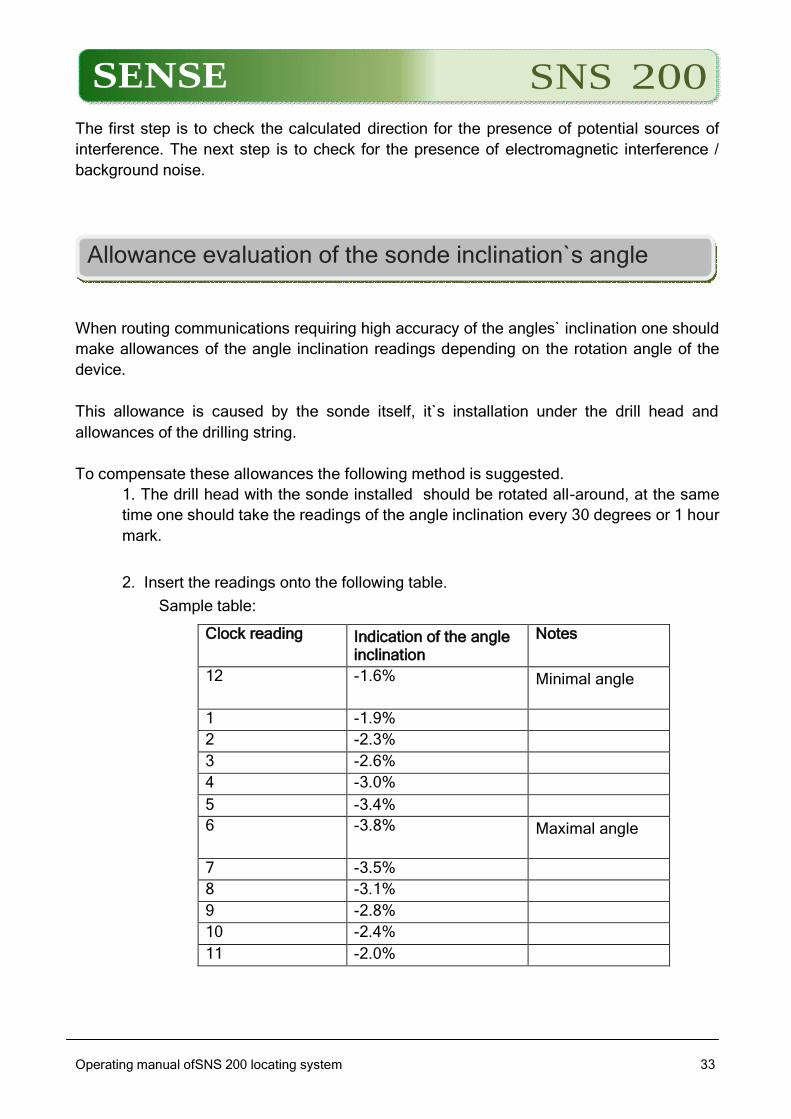
2. Insert the readings onto the following table.
Sample table:
Clock reading Indication of the angle inclination
Notes
12 -1.6% Minimal angle
1 -1.9%
2 -2.3%
3 -2.6%
4 -3.0%
5 -3.4%
6 -3.8% Maximal angle
7 -3.5%
8 -3.1%
9 -2.8%
10 -2.4%
11 -2.0%
SENSE SNS 200
Operating manual ofSNS 200 locating system
3434
3. Choose in the table the lines with the minimum and maximum reading of the angle
inclination (in the example lines 12 and 6 hours)
4. Find the everage angle of these two readings (sum two readings and devide by
two: -1.6+(-3.8)=-5.4; -5.4/2= -2.7%).This very angle (-2.7%)is anupdated
inclination angle.
5. There are two ways to use the present calculation in considiration of the angle
inclination in drilling:
To determine using the table the clock position which gives the clousest reading to the updated angle (in our example it`s 3 and9o`clock).Furthermore take the readings of the angle inclination in this position of the device. Put the device in this position and make sure thet the reading of the angle inclination is equal to the updated angle.
Another way is to determine the allowance for 12 o`clock.
To do this you need to deduct the updated angle from the angle reading at 12 o`clock. (in our example -1.6-(-2.7)=1.1%). Furthermore take the angle readings at 12 o`clock and deduct the allowance. E.g. while drilling we took the angle reading 1.5 % (1.5-1.1=0.4)–the updated reading will be 0.4%.
The rotation of the drill head for allowance evaluation can be done at the beginning when
the head drill is installed into the machine with the first drill bar. Also you can determine the
allowance at control points of the bore pit. To make the evaluation more precise it is
necessary to take readings at the angle equal to zero.
SNS 200 program package
Software and driverCOM-USB installation
Program installation
Move the directory SNSPROfrom the installation CD into the desirable place of your PC
and to start work launch the file from the derictory Sns-Reader.exe.
Installation theCOM-USBdriver and connecting the radiomodem.
SNS-PRO device is connected to a PC on the radio interface via the radiomodem. There is
a driver on the CD. From directory COMUSB-STLab(or TRENDnet) launch the file
Setup.exe.(STLab–if the radiomodem wire is black).
After the driver installation the radiomodem can be connected. Windows system finds a
new device and prepare it for work. For Windows XP system restarting is needed.
SENSE SNS 200
Operating manual ofSNS 200 locating system
3535
The port number given by the system can be seen in ‘Device manager’ – go to Ports Tab
‘COM and LPT’ (while the radiomodem is connected), where there is a line similar to:
‘ProlificUSBto SerialCommport(COM5)’.
The last number in the line must be remembered.While launchingПри запуске
программы Sns-Reader.exe program go to program upper menu Connections-
Parameters and choose the necessary port. It can be done only once. Connect the
radiomodem to a USB connector. If different connectors are used the system gives
different numbers to them and every time the necessary port is to be chosen.
Contents of the installation CD.
DOC–documentation(Program description,Operating manual ofSNS200- PROn).
SNSPRO –program catalogue Sns-Reader. COMUSB–the catalogue contains an installation file of the driver for connecting the radiomodem
SENSE SNS 200
Operating manual ofSNS 200 locating system
3636
Summary
SNS-Reader program is intended for uploading, editing and saving the tables of the
protocols which were obtained while working with SNS200-PROn system.
1.Preparation for work.
Before commencing connect the radiomodem to the computer. If it is the first time that the
radiomodem has been connected to the computer wait until the drivers have been installed.
1.1.Preparing the receiver for work with the program.
The work with the program is carried out in ‘Work with PC’ receiver’s mode. In order to
change for this mode, switch on the receiver, wait until the display on the receiver will show
the main menu and do the following:
SENSE SNS 200
Operating manual ofSNS 200 locating system
3737
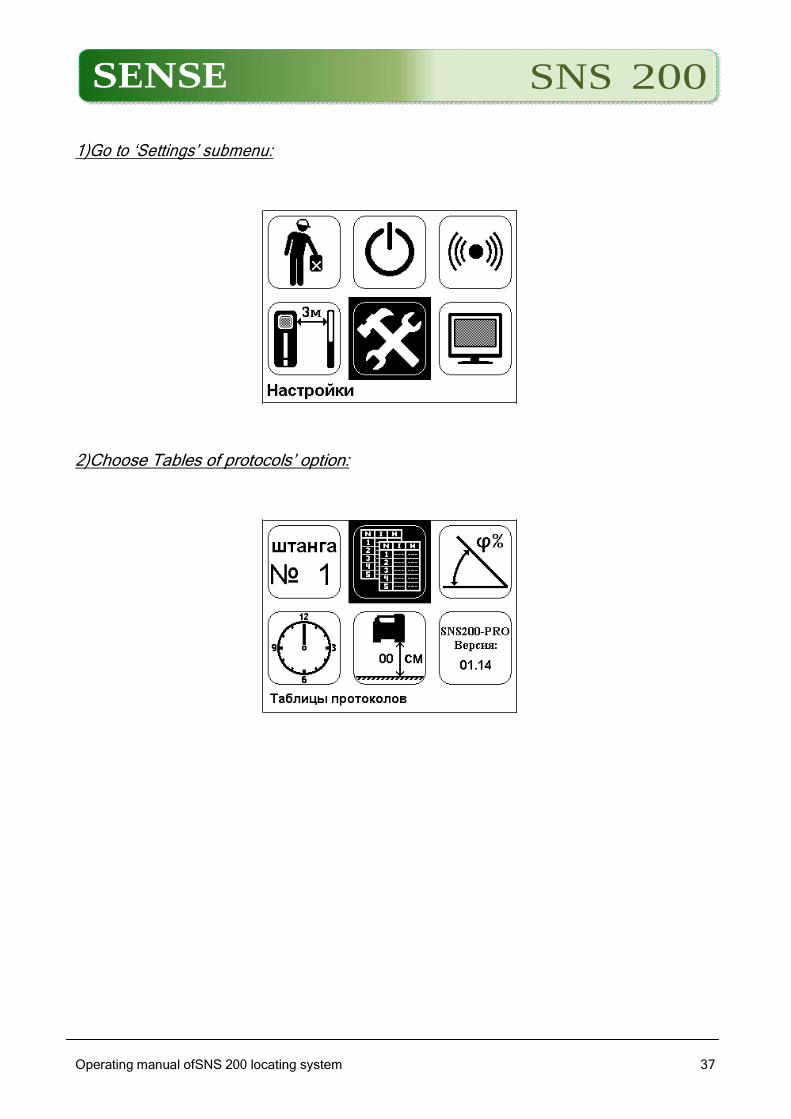
1)Go to ‘Settings’ submenu:
2)Choose Tables of protocols’ option:
SENSE SNS 200
Operating manual ofSNS 200 locating system
3838
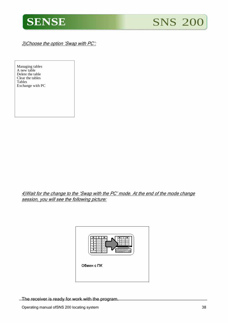
3)Choose the option ‘Swap with PC’:
4)Wait for the change to the ‘Swap with the PC’ mode. At the end of the mode change session, you will see the following picture:
The receiver is ready for work with the program.
Managing tables A new table Delete the table Clear the tables Tables Exchange with PC
SENSE SNS 200
Operating manual ofSNS 200 locating system
3939
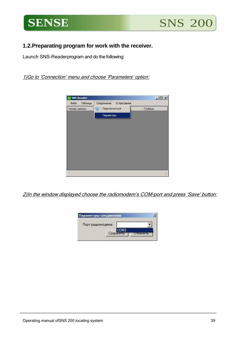
1.2.Preparating program for work with the receiver.
Launch SNS-Readerprogram and do the following:
1)Go to ‘Connection’ menu and choose ‘Parameters’ option:
2)In the window displayed choose the radiomodem’s COM-port and press ‘Save’ button:
SENSE SNS 200
Operating manual ofSNS 200 locating system
4040
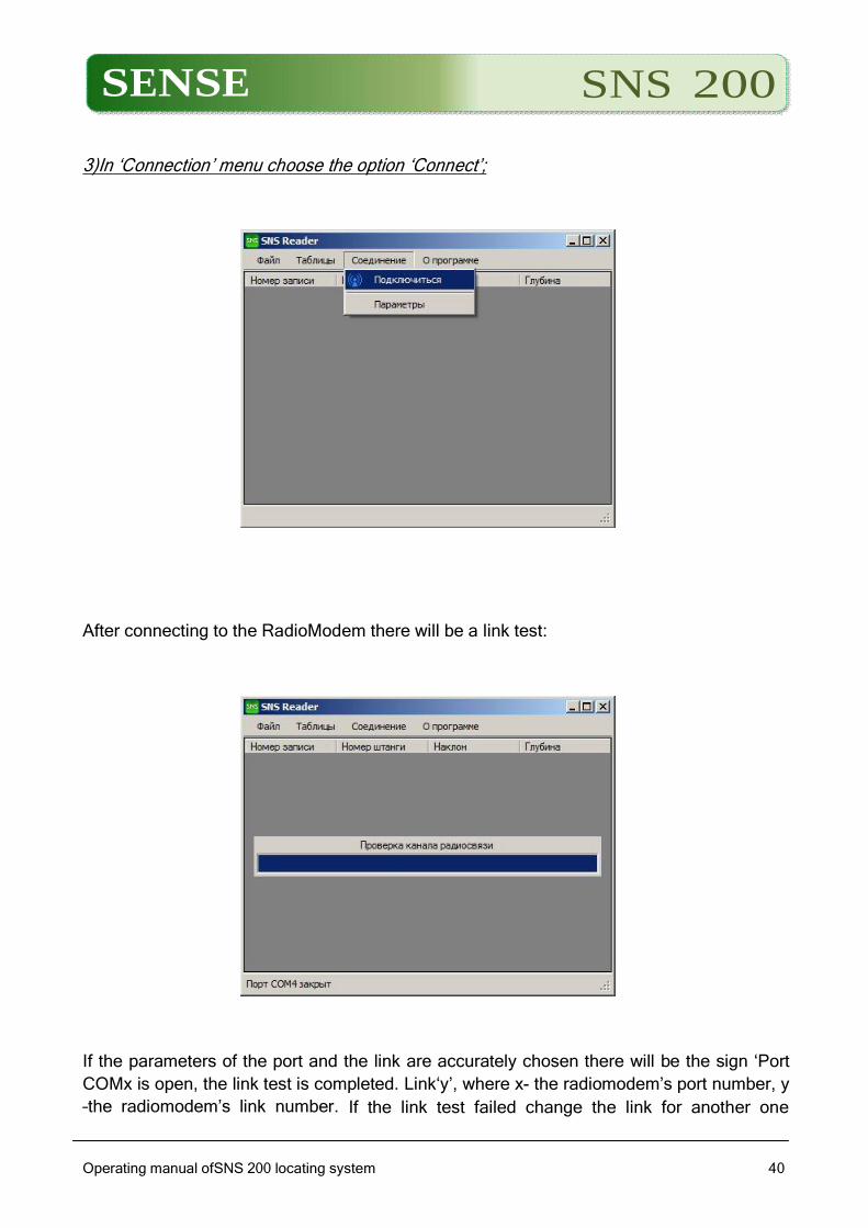
3)In ‘Connection’ menu choose the option ‘Connect’;
After connecting to the RadioModem there will be a link test:
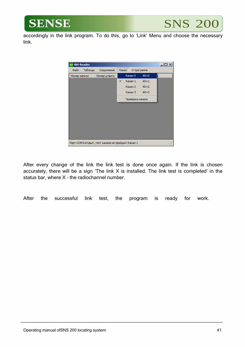
If the parameters of the port and the link are accurately chosen there will be the sign ‘Port
COMx is open, the link test is completed. Link‘y’, where x- the radiomodem’s port number, y
–the radiomodem’s link number. If the link test failed change the link for another one
SENSE SNS 200
Operating manual ofSNS 200 locating system
4141
accordingly in the link program. To do this, go to ‘Link’ Menu and choose the necessary
link.
After every change of the link the link test is done once again. If the link is chosen
accurately, there will be a sign ‘The link X is installed. The link test is completed’ in the
status bar, where X – the radiochannel number.
After the successful link test, the program is ready for work.
SENSE SNS 200
Operating manual ofSNS 200 locating system
4242
2.Uploading tables of protocols from the receiver, their editing and
saving tables into the file.
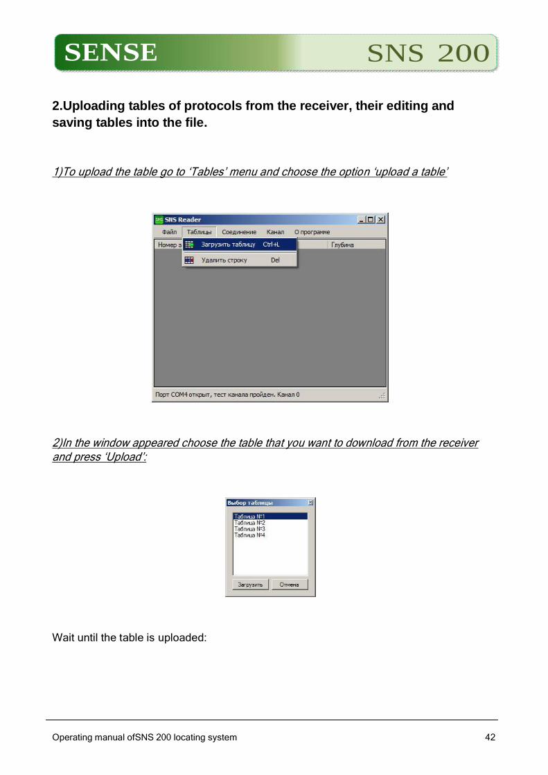
1)To upload the table go to ‘Tables’ menu and choose the option ‘upload a table’
2)In the window appeared choose the table that you want to download from the receiver and press ‘Upload’:
Wait until the table is uploaded:
SENSE SNS 200
Operating manual ofSNS 200 locating system
4343
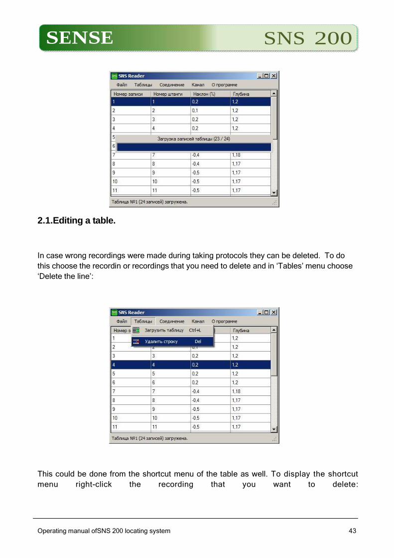
2.1.Editing a table.
In case wrong recordings were made during taking protocols they can be deleted. To do
this choose the recordin or recordings that you need to delete and in ‘Tables’ menu choose
‘Delete the line’:
This could be done from the shortcut menu of the table as well. To display the shortcut
menu right-click the recording that you want to delete:
SENSE SNS 200
Operating manual ofSNS 200 locating system
4444
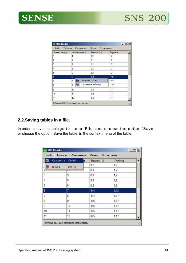
2.2.Saving tables in a file.
In order to save the table,go to menu ‘F i le’ and choose the opt ion ‘Save’
or choose the option ‘Save the table’ in the context menu of the table:
SENSE SNS 200
Operating manual ofSNS 200 locating system
4545
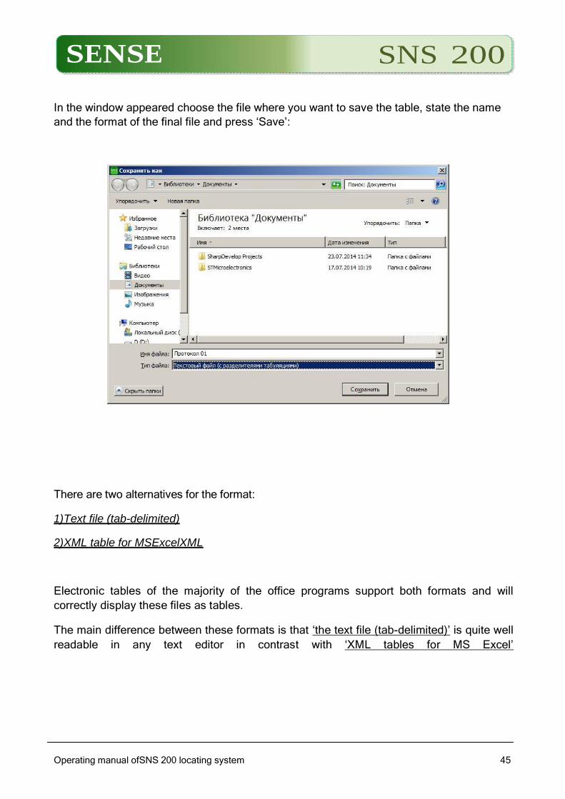
In the window appeared choose the file where you want to save the table, state the name
and the format of the final file and press ‘Save’:
There are two alternatives for the format:
1)Text file (tab-delimited)
2)XML table for MSExcelXML
Electronic tables of the majority of the office programs support both formats and will
correctly display these files as tables.
The main difference between these formats is that ‘the text file (tab-delimited)’ is quite well
readable in any text editor in contrast with ‘XML tables for MS Excel’

SENSE SNS 200
Operating manual ofSNS 200 locating system
4646
Operating and services procedures
Avoid both shocks and vibrations and also the possibility of downfall and external
mechanical damages of the devices.
It is FORBIDDEN for operators to open any device from SNS200 system.
Services procedures are to inspect visually the devices in order to identify mechanical
damages, external cleaning. In case of identifying inconspicuous mechanical damages on
the devices it is necessary to carry out a thorough inspection of its operational
performance.
If there is no opportunity for troubleshooting issues in the system work on your own, one
should contact LLC SENSE, Client service Department maintaining (phone+7(8422)45-72-
00 or45-80-79), where you can get assistance for solving this kind of problems.