Embed Size (px)
Citation preview

ENGLI
SH
DEUTS
CH
Submersible electric pumps with closedsingle- and double-channel impeller
Tauchpumpenmit geschlossenemEinzel- und Doppelkanal-Laufrad
Designed specifically for heavy duty uses in the civil and industrial sectorsSpezifikationen für den Gebrauch unter erschwerten Bedingungen imGewerbe- und Industriebereich
Motors from 18.5 to 37 kw, with 4 and 6 poles4- und 6- polige Motoren von 18,5 bis 37 kW
Set-up for cooling jacketVorrüstung für Kühlmantel
Hydraulics with wide, clear passagesMit großzügig dimensionierten Durchgängen
SMN - SBN

www.zenit.com2
Oil seals’ sensorThis indicates the wear of the first mechanicalseal when the second is still intactÖlprüfsonde DichtungenSignalisiert den Verschleiß der erstenmechanischen Dichtung, wenn die zweite nochunversehrt ist
ImpellerDesigned to prevent cloggingLaufradZum Schutz vor Verstopfungen konzipiert
Electric pumps SMN and SBNDie Elektropumpen SMN und SBN
Double power supply cable Standard length 10 mDoppeltes Stromkabel Standardlänge 10 m
Additional cable for thermistors and oilpurity sensor Standard length 10 mZusatzkabel für Thermistoren undÖlprüfsonde Standardlänge 10 m
Easy maintenanceSpecial design contrivances facilitate impeller removal andmaintenance operationsLeichtere InstandhaltungDie besonderen Konstruktionsmerkmale erleichtern denAusbau des Laufrad und die Instandhaltungsmaßnahmen
Cable clampwith GAS thread, set up for cable ductingKabelniederhaltermit GAS-Gewinde, zum Verrohren des Kabelsvorgerüstet
Lifting handleIn microcast steelHebegriffStahl-Präzisionsguss
Submersible electric pumps with closed single- and double-channel impellerTauchpumpenmit geschlossenem Einzel- und Doppelkanal-Laufrad
Reference legislation:Presidential Decree 459 dated 1996; MACHINE DIRECTIVE 98/37/CE; LOW VOLTAGE DIRECTIVE 73/23/CEE;DIRECTIVE ON ELECTROMAGNETIC COMPATIBILITY 89/336/CEEApplicable standards:EN ISO 12100-1; EN ISO 12100-2; UNI EN 414 CEI EN 60529; CEI EN 60034-1; CEI EN 60034-2; CEI EN 60335-1; CEI EN 60335-2-41 UNI EN 9906;CEI EN 60204; UNI EN 1561; UNI EN 1563; UNI EN 614.Procedures required by Quality System certificate UNI EN 9001:2000, DNV certificate no. CERT 00660-95-AQ-BOL-SINCERTBezugsnormen:DPR 459 von 1996; MASCHINENRICHTLINIE 98/37/EWG; NIEDERSPANNUNGSRICHTLINIE 73/23/EWG;RICHTLINIE ZUR ELEKTROMAGNETISCHEN KOMPATIBILITÄT89/336/EWGangewendete Normen:EN ISO 12100-1; EN ISO 12100-2; UNI EN 414 CEI EN 60529; CEI EN 60034-1; CEI EN 60034-2; CEI EN 60335-1; CEI EN 60335-2-41 UNI EN 9906;CEI EN 60204; UNI EN 1561; UNI EN 1563; UNI EN 614.Vom Qualitätssystem vorgesehene Verfahren UNI EN 9001:2000-Zertifizierung, DNV Nr. CERT 00660-95-AQ-BOL-SINCERT-Zertifizierung
www.zenit.com 3
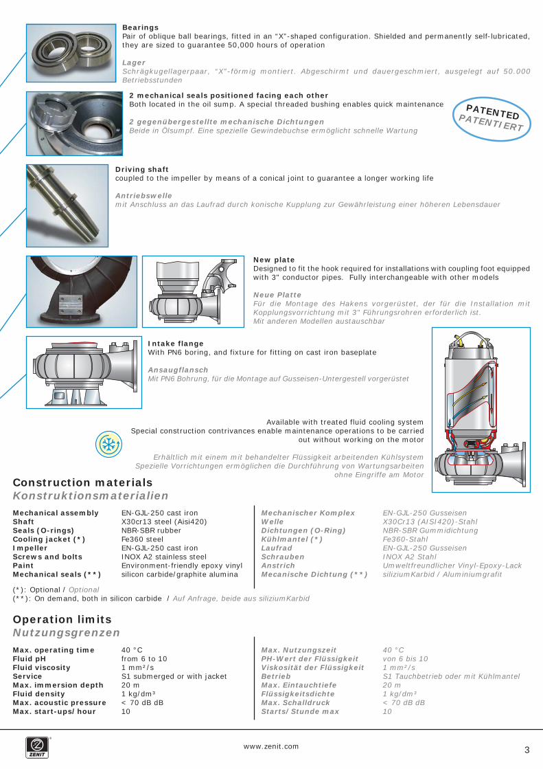
New plateDesigned to fit the hook required for installations with coupling foot equippedwith 3" conductor pipes. Fully interchangeable with other models
Neue PlatteFür die Montage des Hakens vorgerüstet, der für die Installation mitKopplungsvorrichtung mit 3" Führungsrohren erforderlich ist.Mit anderen Modellen austauschbar
2 mechanical seals positioned facing each otherBoth located in the oil sump. A special threaded bushing enables quick maintenance
2 gegenübergestellte mechanische DichtungenBeide in Ölsumpf. Eine spezielle Gewindebuchse ermöglicht schnelle Wartung
Driving shaftcoupled to the impeller by means of a conical joint to guarantee a longer working life
Antriebswellemit Anschluss an das Laufrad durch konische Kupplung zur Gewährleistung einer höheren Lebensdauer
BearingsPair of oblique ball bearings, fitted in an “X”-shaped configuration. Shielded and permanently self-lubricated,they are sized to guarantee 50,000 hours of operation
LagerSchrägkugellagerpaar, “X”-förmig montiert. Abgeschirmt und dauergeschmiert, ausgelegt auf 50.000Betriebsstunden
Intake flangeWith PN6 boring, and fixture for fitting on cast iron baseplate
AnsaugflanschMit PN6 Bohrung, für die Montage auf Gusseisen-Untergestell vorgerüstet
Available with treated fluid cooling systemSpecial construction contrivances enable maintenance operations to be carried
out without working on the motor
Erhältlich mit einem mit behandelter Flüssigkeit arbeitenden KühlsystemSpezielle Vorrichtungen ermöglichen die Durchführung von Wartungsarbeiten
ohne Eingriffe am Motor
PATENTEDPATENTIERT
Mechanical assemblyShaftSeals (O-rings)Cooling jacket (*)ImpellerScrews and boltsPaintMechanical seals (**)
EN-GJL-250 cast ironX30cr13 steel (Aisi420)NBR-SBR rubberFe360 steelEN-GJL-250 cast ironINOX A2 stainless steelEnvironment-friendly epoxy vinylsilicon carbide/graphite alumina
Mechanischer KomplexWelleDichtungen (O-Ring)Kühlmantel (*)LaufradSchraubenAnstrichMecanische Dichtung (**)
EN-GJL-250 GusseisenX30Cr13 (AISI420)-StahlNBR-SBR GummidichtungFe360-StahlEN-GJL-250 GusseisenINOX A2 StahlUmweltfreundlicher Vinyl-Epoxy-LacksiliziumKarbid / Aluminiumgrafit
Construction materialsKonstruktionsmaterialien
Operation limitsNutzungsgrenzen
(*): Optional / Optional(**): On demand, both in silicon carbide / Auf Anfrage, beide aus siliziumKarbid
Max. operating timeFluid pHFluid viscosityServiceMax. immersion depthFluid densityMax. acoustic pressureMax. start-ups/hour
40 °Cfrom 6 to 101 mm²/sS1 submerged or with jacket20 m1 kg/dm³< 70 dB dB10
Max. NutzungszeitPH-Wert der FlüssigkeitViskosität der FlüssigkeitBetriebMax. EintauchtiefeFlüssigkeitsdichteMax. SchalldruckStarts/Stunde max
40 °Cvon 6 bis 101 mm²/sS1 Tauchbetrieb oder mit Kühlmantel20 m1 kg/dm³< 70 dB dB10

www.zenit.com4
B
A
22 4 150-200-250
22÷37 4 150
Closed mono-channelTyp einkanalig
Closed two-channelTyp zweikanalig
Capacity (Q)Durchfluß (Q)
Head (
H)
Förd
erh
öhe (
H)
Capacity (Q)Durchfluß (Q)
Head (
H)
Förd
erh
öhe (
H)
Curve groupingsZusammenstellung der Kennlinien
GR
OU
PIN
GZU
SA
MM
EN
STELLU
NG
GR
OU
PIN
GZU
SA
MM
EN
STELLU
NG
ImpellerLaufrad
kWkW
PolesPole
Ø Outlet (mm)Ø Vorlaufs (mm)
ImpellerLaufrad
kWkW
Ø Outlet (mm)Ø Vorlaufs (mm)
PolesPolos

www.zenit.com 5
D
C
4 200
22÷37 4 250
22÷37
6 150-250-30018.5÷22
E
Capacity (Q)Durchfluß (Q)
Head (
H)
Förd
erh
öhe (
H)
Capacity (Q)Durchfluß (Q)
Head (
H)
Förd
erh
öhe (
H)
Capacity (Q)Durchfluß (Q)
Head (
H)
Förd
erh
öhe (
H)
GR
OU
PIN
GZU
SA
MM
EN
STELLU
NG
GR
OU
PIN
GZU
SA
MM
EN
STELLU
NG
GR
OU
PIN
GZU
SA
MM
EN
STELLU
NG
ImpellerLaufrad
kWkW
PolesPole
Ø Outlet (mm)Ø Vorlaufs (mm)
ImpellerLaufrad
kWkW
PolesPole
Ø Outlet (mm)Ø Vorlaufs (mm)
ImpellerLaufrad
kWkW
PolesPole
Ø Outlet (mm)Ø Vorlaufs (mm)

www.zenit.com6
SBN 3000/4/150 F1LT-E
SMN 3000/4/150 A1LT-E SMN 3000/4/200 A1LT-E
SBN 4000/4/150 G1LT-E SBN 3000/4/150 A1LT-E
SMN 3000/4/250 A1LT-EA3
A1 A2
B1
B2 B3
Capacity (Q) Durchfluß (Q)
Head (
H)
F
örd
erh
öhe (
H)
Pow
er
L
eis
tung
Eff
icie
ncy
(r)
Le
istu
ngsg
rad (
r)
Capacity (Q) Durchfluß (Q)
Head (
H)
F
örd
erh
öhe (
H)
Pow
er
L
eis
tung
Eff
icie
ncy
(r)
Le
istu
ngsg
rad (
r)
Capacity (Q) Durchfluß (Q)
Head (
H)
F
örd
erh
öhe (
H)
Pow
er
L
eis
tung
Eff
icie
ncy
(r)
Le
istu
ngsg
rad (
r)
Capacity (Q) Durchfluß (Q)
Head (
H)
F
örd
erh
öhe (
H)
Pow
er
L
eis
tung
Eff
icie
ncy
(r)
Le
istu
ngsg
rad (
r)
Capacity (Q) Durchfluß (Q)
Head (
H)
F
örd
erh
öhe (
H)
Pow
er
L
eis
tung
Eff
icie
ncy
(r)
Le
istu
ngsg
rad (
r)
Capacity (Q) Durchfluß (Q)
Head (
H)
F
örd
erh
öhe (
H)
Pow
er
L
eis
tung
Eff
icie
ncy
(r)
Le
istu
ngsg
rad (
r)
Hydraulic curvesHydraulische Kennlinien

www.zenit.com7
SBN 4000/4/150 F1LT-E
SBN 5000/4/150 A1LT-ESBN 5000/4/150 F1LT-E
SBN 5000/4/150 H1LT-E SBN 5000/4/150 G1LT-E
SBN 4000/4/150 A1LT-EB4 B5
B6 B7
B8 B9
Capacity (Q) Durchfluß (Q)
Head (
H)
F
örd
erh
öhe (
H)
Pow
er
L
eis
tung
Eff
icie
ncy
(r)
Le
istu
ngsg
rad (
r)
Capacity (Q) Durchfluß (Q)H
ead (
H)
F
örd
erh
öhe (
H)
Pow
er
L
eis
tung
Eff
icie
ncy
(r)
Le
istu
ngsg
rad (
r)
Capacity (Q) Durchfluß (Q)
Head (
H)
F
örd
erh
öhe (
H)
Pow
er
L
eis
tung
Eff
icie
ncy
(r)
Le
istu
ngsg
rad (
r)
Capacity (Q) Durchfluß (Q)
Head (
H)
F
örd
erh
öhe (
H)
Pow
er
L
eis
tung
Eff
icie
ncy
(r)
Le
istu
ngsg
rad (
r)
Capacity (Q) Durchfluß (Q)
Head (
H)
F
örd
erh
öhe (
H)
Pow
er
L
eis
tung
Eff
icie
ncy
(r)
Le
istu
ngsg
rad (
r)
Capacity (Q) Durchfluß (Q)
Head (
H)
F
örd
erh
öhe (
H)
Pow
er
L
eis
tung
Eff
icie
ncy
(r)
Le
istu
ngsg
rad (
r)

www.zenit.com8
SBN 3000/4/250 A1LT-E
SBN 4000/4/250 A1LT-E SBN 5000/4/250 A1LT-E
SBN 3000/4/200 A1LT-E SBN 4000/4/200 A1LT-E
SBN 5000/4/200 A1LT-E
C2
D3
D1
D2
C3
C1
Capacity (Q) Durchfluß (Q)
Head (
H)
F
örd
erh
öhe (
H)
Pow
er
L
eis
tung
Eff
icie
ncy
(r)
Le
istu
ngsg
rad (
r)
Capacity (Q) Durchfluß (Q)
Head (
H)
F
örd
erh
öhe (
H)
Pow
er
L
eis
tung
Eff
icie
ncy
(r)
Le
istu
ngsg
rad (
r)
Capacity (Q) Durchfluß (Q)
Head (
H)
F
örd
erh
öhe (
H)
Pow
er
L
eis
tung
Eff
icie
ncy
(r)
Le
istu
ngsg
rad (
r)
Capacity (Q) Durchfluß (Q)
Head (
H)
F
örd
erh
öhe (
H)
Pow
er
L
eis
tung
Eff
icie
ncy
(r)
Le
istu
ngsg
rad (
r)
Capacity (Q) Durchfluß (Q)
Head (
H)
F
örd
erh
öhe (
H)
Pow
er
L
eis
tung
Eff
icie
ncy
(r)
Le
istu
ngsg
rad (
r)
Capacity (Q) Durchfluß (Q)
Head (
H)
F
örd
erh
öhe (
H)
Pow
er
L
eis
tung
Eff
icie
ncy
(r)
Le
istu
ngsg
rad (
r)

www.zenit.com 9
SBN 2500/6/150 A1LT-E
SBN 3000/6/300 A1LT-E
SBN 2500/6/300 A1LT-E
E1
E3
E4 E5SBN 3000/6/250 A2LT-E
SBN 5000/4/250 B1LT-E
E2 SBN 2500/6/250 A2LT-E
D4
Capacity (Q) Durchfluß (Q)
Head (
H)
F
örd
erh
öhe (
H)
Pow
er
L
eis
tung
Eff
icie
ncy
(r)
Le
istu
ngsg
rad (
r)
Capacity (Q) Durchfluß (Q)
Head (
H)
F
örd
erh
öhe (
H)
Pow
er
L
eis
tung
Eff
icie
ncy
(r)
Le
istu
ngsg
rad (
r)
Capacity (Q) Durchfluß (Q)
Head (
H)
F
örd
erh
öhe (
H)
Pow
er
L
eis
tung
Eff
icie
ncy
(r)
Le
istu
ngsg
rad (
r)
Capacity (Q) Durchfluß (Q)
Head (
H)
F
örd
erh
öhe (
H)
Pow
er
L
eis
tung
Eff
icie
ncy
(r)
Le
istu
ngsg
rad (
r)
Capacity (Q) Durchfluß (Q)
Head (
H)
F
örd
erh
öhe (
H)
Pow
er
L
eis
tung
Eff
icie
ncy
(r)
Le
istu
ngsg
rad (
r)
Capacity (Q) Durchfluß (Q)
Head (
H)
F
örd
erh
öhe (
H)
Pow
er
L
eis
tung
Eff
icie
ncy
(r)
Le
istu
ngsg
rad (
r)

www.zenit.com10
SpecificationsTechnische Daten
Power supply voltage: 3~ 400/ 700VStar/Triangle start-upMax. start-ups per hour: 10Service: S1Protection: IP 68Insulation class: HImpeller: a = closed single-channel
b = closed double-channel(*)Cable: c = H07RN-F 2x4G6 10 mt + H07RN-F 4G1,5 10 mt
d = H07RN-F 2x4G10 10 mt + + H07RN-F 4G1,5 10 mt
Speisespannung: 3~ 400/700VAnlassen Stern/Dreieckmax. Starts pro Stunde: 10Betrieb: S1Schutzgrad: IP 68Isolierungsklasse: HLaufrad: a = geschlossener Einzelkanal
b = geschlossener Doppelkanal(*)Kabel: c = H07RN-F 2x4G6 10 mt + H07RN-F 4G1,5 10 mt
d = H07RN-F 2x4G10 10 mt + + H07RN-F 4G1,5 10 mt
392393402385385410410410423423423423385410423393418431520410480520520540
A1A2A3B1B2B3B4B5B6B7B8B9C1C2C3D1D2D3D4E1E2E3E4E5
aaabbbbbbbbbbbbbbbbbbbbb
DN 150DN 200DN 250DN 150DN 150DN 150DN 150DN 150DN 150DN 150DN 150DN 150DN 200DN 200DN 200DN 250DN 250DN 250DN 250DN 150DN 250DN 300DN 250DN 300
100x130100x130100x13082x9082x9082x9082x9082x9082x9082x9082x9082x90
105x140105x140105x140105x140105x140105x140
13582x90130130130130
2626262626363636
44.544.544.544.52636
44.52636
44.544.522.822.822.826.726.7
22222222223030303737373722303722303737
18.518.518.52222
444444444444444444466666
43.543.543.543.543.561616176767676
43.56176
43.56176764040404646
193193193193193271271271337337337337193271337193271337337177177177204204
cccccdddddddcddcdddccccc
Hydraulic dataHydraulik-Daten
CurveKennlinie
CodeCode
ModelModell
ImpellerLaufrad
DeliveryFörderleistung
(PN10)
Free passageFreier Durchfluss
(mm)
Power (kW)Leistung (kW) Poles
PoleP1 P2
Current (A)Strom (A) Cable(*)
Kabel(*) KgRun Start
SMN 3000/4/150 A1LTSMN 3000/4/200 A1LTSMN 3000/4/250 A1LT
---
000
10600
36
201200
72
301800
108
402400
144
503000
180
603600
216
704200
252
804800
288
905400
324
1006000
360
1207200
432
1408400
504
17010200
612
---
---
24.525.526.7
22.423.525.2
2122.123.7
19.921
22.2
18.719.620.8
17.218
19.4
15.616.417.9
13.815
16.4
1012.213.3
5.48.410
2.54.2
l/sl/minm3/h
A1A2A3
l/sl/minm3/h
000
201200
72
402400
144
603600
216
804800
288
1006000
360
1207200
432
1408400
504
1609600
576
18010800
648
20012000
720
24014400
864
280168001008
320192001152
340204001224
B1B2B3B4B5B6B7B8B9C1C2C3D1D2D3D4E1E2E3E4E5
3224.422.821.6
4641.6
3624.5
2453
50.547
41.832.230.4
2823.615.2
1617.217.5
26.520.821.620.438.535.229.222.7
2246.2
4339.534.929.828.125.120.614.614.816.416.6
24.51920
18.935.532.526.521.220.342.439.436.132.127.6
2623.518.213.813.815.515.7
2216.718.217.233.530.5
2520
18.739.536.933.8
3025.824.222.116.312.912.914.7
15
14.216.215.6
26.622.518.717.5
33.630.4
2724
22.621
14.512
12.214
14.1
11.314.4
14
19.517.516.2
2722.122.521.120.412.611.211.513.213.3
7.212.512.4
16.21615
18.520.819.619.5
1010.510.812.712.5
2.711
10.9
14.513.8
1918.118.45.79.51012
11.6
9.29.4
12.812.5
17.216.7
17
99.2
11.310.7
7.47.7
11.311.2
15.51516
8.28.4
10.59.8
5.26
9.59.8
13.713.514.8
7.27.49.68.9
66.8
109.5
12.1
3.65.27.6
7
3.1
5.85
9.3
3.25.6
5
6
3.42.5
3.8
2.31
048804890490048404850491049204930496049704980499048604940500048704950501094005020847050408480506
SBN 3000/4/150 F1LTSBN 3000/4/150 A1LTSBN 3000/4/200 A1LTSBN 3000/4/250 A1LTSBN 4000/4/150 G1LTSBN 4000/4/150 F1LTSBN 4000/4/150 A1LTSBN 4000/4/200 A1LTSBN 4000/4/250 A1LTSBN 5000/4/150 H1LTSBN 5000/4/150 G1LTSBN 5000/4/150 F1LTSBN 5000/4/150 A1LTSBN 5000/4/200 A1LTSBN 5000/4/250 A1LTSBN 5000/4/250 B1LTSBN 2500/6/150 A1LTSBN 2500/6/250 A2LTSBN 2500/6/300 A1LTSBN 3000/6/250 A2LTSBN 3000/6/300 A1LT
SMN 3000/4/150 A1LTSMN 3000/4/200 A1LTSMN 3000/4/250 A1LTSBN 3000/4/150 F1LTSBN 3000/4/150 A1LTSBN 4000/4/150 G1LTSBN 4000/4/150 F1LTSBN 4000/4/150 A1LTSBN 5000/4/150 H1LTSBN 5000/4/150 G1LTSBN 5000/4/150 F1LTSBN 5000/4/150 A1LTSBN 3000/4/200 A1LTSBN 4000/4/200 A1LTSBN 5000/4/200 A1LTSBN 3000/4/250 A1LTSBN 4000/4/250 A1LTSBN 5000/4/250 A1LTSBN 5000/4/250 B1LTSBN 2500/6/150 A1LTSBN 2500/6/250 A2LTSBN 2500/6/300 A1LTSBN 3000/6/250 A2LTSBN 3000/6/300 A1LT

www.zenit.com 11
FREE INSTALLATIONFREIE INSTALLATION
Nodular cast iron baseplateUntergestell aus Sphäroguss
OutletVorlauföffnung
InletAnsaugöffnung
A(mm)649700787698700787698700787698700787698878941878941
Dmin(mm)68074083672674083672674083672674083672693010029301002
DNm(mm)150200250150200250150200250150200250150250300250300
H(mm)11991201123111571201123111571206123111571206123111571275129812751298
H1(mm)173173173173173173173173173173173173173173173173173
P1(mm)285340395285340395285340395285340395285445445445445
Q2(mm)280280280225295295225295295225295295225395395395395
R2(mm)192192192150216216150216216150216216150300300300300
S1°
4545304545304545304545304530303030
S2°
4545454530304530304530304530303030
T1(mm)
2222242422242422242422242422222222
T2(mm)M16M16M16M16M20M20M16M20M20M16M20M20M16M20M20M20M20
Overall dimensionsAbmessungen
SMN 3000/4/150 A1LTSMN 3000/4/200 A1LTSMN 3000/4/250 A1LTSBN 3000/4/150 F(A)1LTSBN 3000/4/200 A1LTSBN 3000/4/250 A1LTSBN 4000/4/150 G(F)(A)1LTSBN 4000/4/200 A1LTSBN 4000/4/250 A1LTSBN 5000/4/150 H(H)(F)(A)1LTSBN 5000/4/200 A1LTSBN 5000/4/250 A(B)1LTSBN 2500/6/150 A1LTSBN 2500/6/250 A2LTSBN 2500/6/300 A1LTSBN 3000/6/250 A2LTSBN 3000/6/300 A1LT

www.zenit.com12
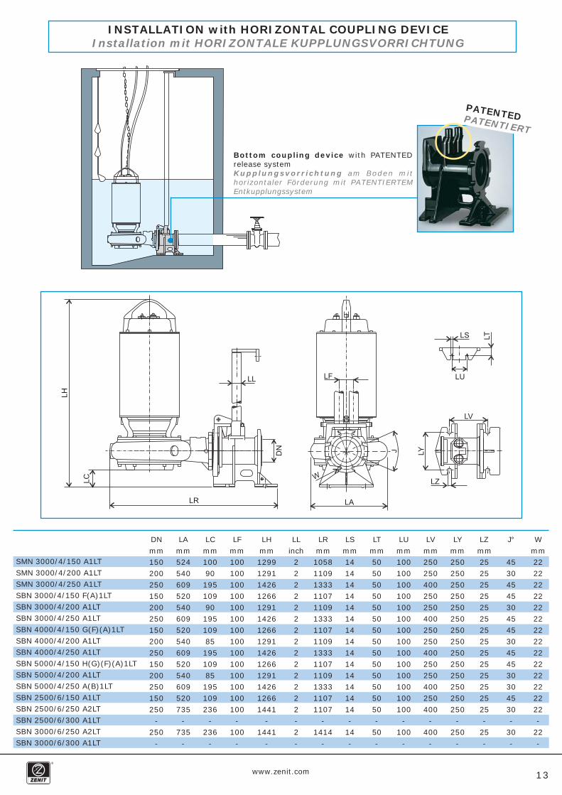
Bottom-fitted coupling devicewith vertical delivery and PATENTED release systemKupplungsvorrichtung am Boden mit vertikalerFörderung mit PATENTIERTEM Entkupplungssystem
No step is required at the bottom of the tankEs ist keine Stufe auf dem Beckenboden erforderlich
ShutterAbsperrschieber
INSTALLATION with VERTICAL COUPLING DEVICEInstallation mit VERTIKALE KUPPLUNGSVORRICHTUNG
DNmm200250300200250300200250300200250300200300350300350
FAmm524540609520540609520540609520540609520735787735787
FFmm100100100100100100100100100100100100100100130100130
FHmm14671422157614341422157614341422157614341422157614341646157116461571
FLinch
22222222222222323
FPmm603605803603605803603605803603605803603803850803850
FRmm12801409160213291409160213291409160213291409160213291514177115141771
FSmm1414141414141414141414141414201420
FTmm5050505050505050505050505050755075
FUmm100100100100100100100100100100100100100100180100180
FVmm280500500280500500280500500280500500280500500500500
FYmm250250250250250250250250250250250250250250460250460
FZmm2525252525252525252525252525252525
J°
4530304530304530304530304530223022
Wmm2222222222222222222222222222222222
FCmm268221345277221345277216345277216345277
272371272
SMN 3000/4/150 A1LTSMN 3000/4/200 A1LTSMN 3000/4/250 A1LTSBN 3000/4/150 F(A)1LTSBN 3000/4/200 A1LTSBN 3000/4/250 A1LTSBN 4000/4/150 G(F)(A)1LTSBN 4000/4/200 A1LTSBN 4000/4/250 A1LTSBN 5000/4/150 H(G)(F)(A)1LTSBN 5000/4/200 A1LTSBN 5000/4/250 A(B)1LTSBN 2500/6/150 A1LTSBN 2500/6/250 A2LTSBN 2500/6/300 A1LTSBN 3000/6/250 A2LTSBN 3000/6/300 A1LT
www.zenit.com 13
Bottom coupling device with PATENTEDrelease systemKupplungsvorrichtung am Boden mithorizontaler Förderung mit PATENTIERTEMEntkupplungssystem
PATENTEDPATENTIERT
INSTALLATION with HORIZONTAL COUPLING DEVICEInstallation mit HORIZONTALE KUPPLUNGSVORRICHTUNG
DNmm150200250150200250150200250150200250150250
-250
-
LFmm100100100100100100100100100100100100100100
-100
-
LRmm10581109133311071109133311071109133311071109133311071107
-1414
-
LAmm524540609520540609520540609520540609520735
-735
-
LHmm12991291142612661291142612661291142612661291142612661441
-1441
-
LCmm10090195109901951098519510985195109236
-236
-
LLinch
22222222222222-2-
LSmm1414141414141414141414141414-
14-
Wmm2222222222222222222222222222-
22-
J°
4530454530454530454530304530-
30-
LTmm5050505050505050505050505050-
50-
LUmm100100100100100100100100100100100100100100
-100
-
LVmm250250400250250400250250400250250400250400
-400
-
LYmm250250250250250250250250250250250250250250
-250
-
LZmm2525252525252525252525252525-
25-
SMN 3000/4/150 A1LTSMN 3000/4/200 A1LTSMN 3000/4/250 A1LTSBN 3000/4/150 F(A)1LTSBN 3000/4/200 A1LTSBN 3000/4/250 A1LTSBN 4000/4/150 G(F)(A)1LTSBN 4000/4/200 A1LTSBN 4000/4/250 A1LTSBN 5000/4/150 H(G)(F)(A)1LTSBN 5000/4/200 A1LTSBN 5000/4/250 A(B)1LTSBN 2500/6/150 A1LTSBN 2500/6/250 A2LTSBN 2500/6/300 A1LTSBN 3000/6/250 A2LTSBN 3000/6/300 A1LT
www.zenit.com14
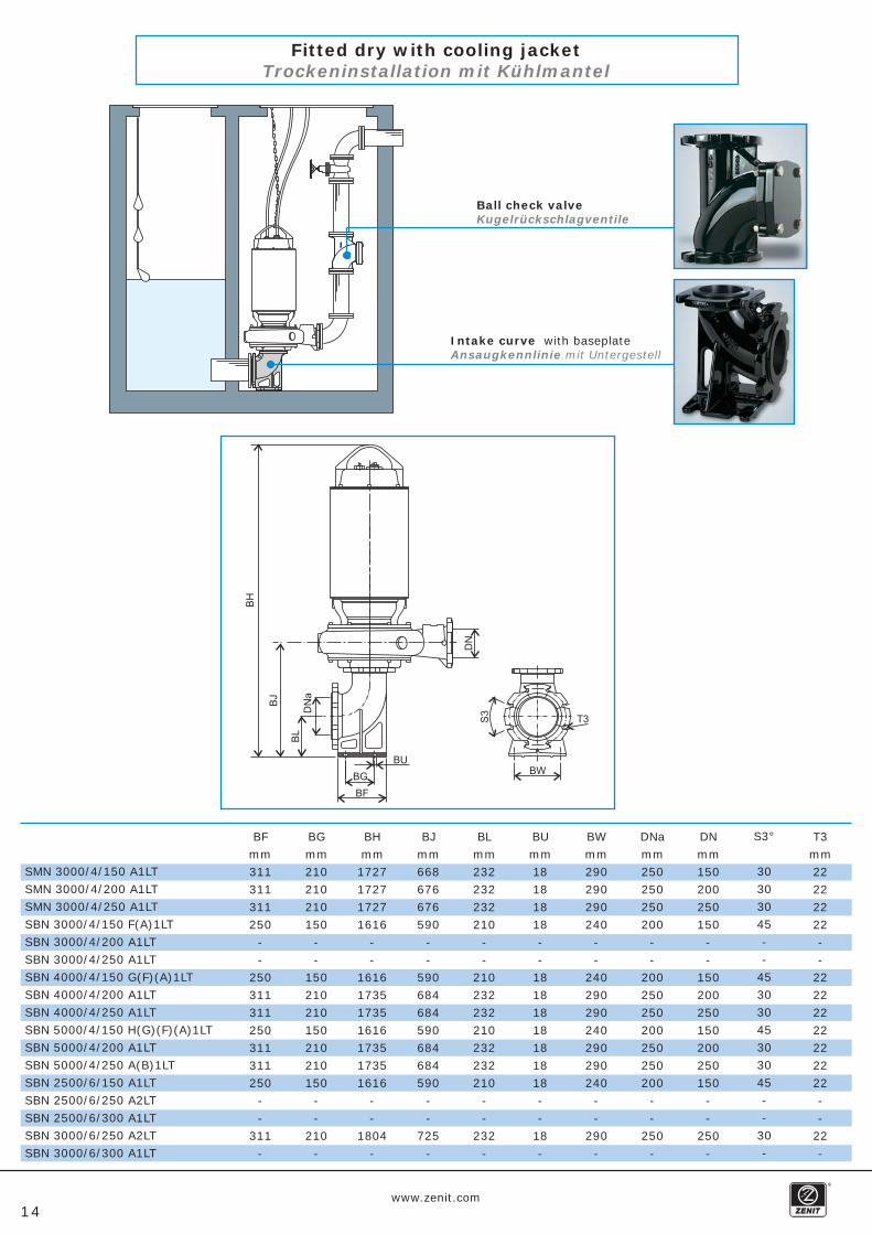
Fitted dry with cooling jacketTrockeninstallation mit Kühlmantel
Intake curve with baseplateAnsaugkennlinie mit Untergestell
Ball check valveKugelrückschlagventile
BFmm311311311250
--
250311311250311311250
--
311-
BGmm210210210150
--
150210210150210210150
--
210-
BHmm1727172717271616
--
1616173517351616173517351616
--
1804-
BLmm232232232210
--
210232232210232232210
--
232-
BUmm18181818--
18181818181818--
18-
BWmm290290290240
--
240290290240290290240
--
290-
DNamm250250250200
--
200250250200250250200
--
250-
DNmm150200250150
--
150200250150200250150
--
250-
S3°
30303045--
45303045303045--
30-
T3mm22222222--
22222222222222--
22-
BJmm668676676590
--
590684684590684684590
--
725-
SMN 3000/4/150 A1LTSMN 3000/4/200 A1LTSMN 3000/4/250 A1LTSBN 3000/4/150 F(A)1LTSBN 3000/4/200 A1LTSBN 3000/4/250 A1LTSBN 4000/4/150 G(F)(A)1LTSBN 4000/4/200 A1LTSBN 4000/4/250 A1LTSBN 5000/4/150 H(G)(F)(A)1LTSBN 5000/4/200 A1LTSBN 5000/4/250 A(B)1LTSBN 2500/6/150 A1LTSBN 2500/6/250 A2LTSBN 2500/6/300 A1LTSBN 3000/6/250 A2LTSBN 3000/6/300 A1LT

www.zenit.com15
Complementary productsErgänzende Produkte
Disk and tubular bottom diffusersSuitable for installations in industrial and civil ventilation systems, they can be supplied with a
drilled membrane for small or large bubbles.The accessories supplied with the system have been designed to reduce assembly times and to
guarantee high level performances over time.
Bodendiffusoren in Scheiben- und RöhrenformSie eignen sich zur Installation in gewerblichen und industriellen Belüftungssystemen und können
mit Membran mit Öffnungen für feine oder große Blasen ausgestattet werden.Die Zubehörelemente wurden zur Verringerung der Montagezeiten und Garantie konstant hoher
Leistungen konzipiert.
OXYGEN oxygenation systemsThe OXYGEN 80, 100 and 150 ejectors feature an interchangeable screen with apolyurethane coating (Vulkollan), which is highly corrosion-resistant and, securedwith screws, can be quickly replaced, facilitating plant calibration and any maintenanceinterventions that may be required.
Sauerstoffaufnahmesystem OXYGENDie OXYGEN-Ejektorvorrichtungen 80, 100 und 150 besitzen ein austauschbares Diaphragma, dasmit hochkorrosionsbeständigem Polyurethanmaterial (Vulkollan) beschichtet ist. Es wird mit Schraubenbefestigt und kann schnell ausgewechselt werden, wodurch die Anlageneichung und eventuelleWartungsarbeiten erleichtert werden.
Submerged electric mixersSubmerged mixers represent essential components in modern water treatment plants. Availablemodels range from 1.1 to 15 kw, with 4 and 6 poles.They come complete with installation accessories in a galvanised or stainless steel structuralwork and hoisting winch.
ElektrotauchmischerTauchmischer sind wesentliche Bestandteile moderner Wasseraufbereitungsanlagen. Erhältlichsind 4- und 6-polige Modelle von 1,1 bis 15 kW.Komplett mit Installationszubehör aus verzinktem Metall oder Nirosta und Hubwinde.
Flow valveSet-up for easy installation on the Zenit SMN and SBN electric pumps. Every time the system is started up, itensures the water from the collection tank is stirred up to prevent any generation of sediment. Equipped with
an opening cycle timer.
DurchflussventilDas leicht an den Elektropumpen SMN und SBN installierbare Ventil ermöglicht bei jedem Start die Bewegungdes Wassers im Sammelbecken, wodurch die Sedimentbildung verhindert wird. Mit Öffnungszeit-Regulierung
ausgestattet.
Commander 20 and Commander 50Control unit for automated plant management. Up to 5 pumps can be monitored, by setting start-uptimes and operating thresholds. In addition to the standard visual alarms and buzzers, it also signalsfailures or malfunctions remotely, via SMS text messages.
Commander 20 und Commander 50Steuergerät für die automatische Anlagensteuerung. Kontrollmöglichkeit für bis zu 5 Pumpen durchEinstellen der Starts und Eingriffsschwellen. Außer normalen akustischen und visuellen Warnsystemensignalisiert es Betriebsstörungen auch auf Distanz per SMS.
Electric equipmentA wide range of electric panels and accessories is available to customers
on request
Elektrische GeräteAuf Anfrage des Kunden ist eine umfangreiche Palette von Schalttafeln
und Zubehör erhältlich
PATENTED
PATENTIERT
The information contained herein is not binding.Zenit reserves the right to alter the product without prior notice
Die aufgeführten Daten sind nicht als verbindlich anzusehen.Zenit behält sich das Recht auf Abänderung des Produktes ohne Vorankündigung vor
Cod. 29040060341200000_3Rev. 3 - 30/12/06
www.zenit.com [email protected]