Embed Size (px)
Citation preview

Chapter 12
Smart Technical Textiles Based on Fiber Optic Sensors
Katerina Krebber
Additional information is available at the end of the chapter
http://dx.doi.org/10.5772/54244
1. Introduction
Smart technical textiles are by definition textiles that can interact with their environment.They can sense and react to environmental conditions and external stimuli from mechanical,thermal, chemical or other sources. Such textiles are multifunctional or even “intelligent”which is fulfilled by a number of sensors incorporated in the textiles. The embedded sensorsare sensitive to various parameters such as temperature, strain, chemical, biological and oth‐er substances.
Technical textiles are commonly used within several industrial sectors ranging from medi‐cal, healthcare, earthworks, construction, civil engineering, transport, to name a few. Europehas driven substantial developments in technical textile technologies[1]. Smart technical tex‐tiles are going to stimulate the European engineering, transportation and construction in‐dustry and to improve human performance and health. For example, technical textiles areextensively used in construction in form of geotextiles for the reinforcement of earthworksand masonry structures. The retrofitting of existing masonry walls and soils structures bytechnical textiles gains more and more importance especially in connection with earthquakeprotection of historic buildings and protection of roads and railway embankments againstlandslides. Wearable health systems and protective clothing have been recognized as keytechnologies to improve the personal protection and health care of Europe’s citizens[2].Smart biomedical garments and clothing act as “a second skin” and detect, for instance, vitalsignals of the wearer’s body or changes in the wearer’s environment.
The most effort in the past was made to integrate non-optical sensors into textiles. Opticalfibers integrated in textiles were mostly explored for illumination or luminescent purposes.Smart technical textiles containing fiber optic sensors are still an exception. When integra‐tion of sensors into textiles is considered, optical fibers have a serious advantage over otherkinds of sensors due to their fibrous nature. The optical fiber is similar to textile fibers and
© 2013 Krebber; licensee InTech. This is an open access article distributed under the terms of the CreativeCommons Attribution License (http://creativecommons.org/licenses/by/3.0), which permits unrestricted use,distribution, and reproduction in any medium, provided the original work is properly cited.

can be ideally processed like standard textile yarns. Particularly, the integration of polymeroptical fibers (POF), with their outstanding material properties, into technical textiles hasnot seriously been considered, until now. POF offer additional benefits to users. They arelightweight, robust, cheap and easy to handle. Especially because of their high elasticity andhigh breakdown strain POF are ideally suited for integration into technical textiles[3].
2. Geotextiles based on distributed fiber optic sensors for structuralhealth monitoring
For stabilization and reinforcement of geotechnical structures like dikes, dams, railways,embankments, landfills and slopes geotextiles are commonly used. The incorporation of op‐tical fibers in geotextiles leads to additional functionalities of the textiles, e.g. monitoring ofmechanical deformation, strain, temperature, humidity, pore pressure, detection of chemi‐cals, measurement of the structural integrity and the health of the geotechnical structure(structural health monitoring). Especially solutions for distributed measurement of mechani‐cal deformations over extended areas of some hundred meters up to some kilometers are ur‐gently needed. Textile-integrated distributed fiber optic sensors can provide for any positionof extended geotechnical structures information about critical soil displacement or slopeslides via distributed strain measurement along the fiber with a high spatial resolution ofless than 1 m. So an early detection of failures and damages in geotechnical structures ofhigh risk potential can be ensured.
Geotextiles with incorporated fiber optic sensors based on fiber Bragg gratins (FBG) weredemonstrated in the past[4]. Monitoring systems based on such geotextiles can only meas‐ure quasi-distributed strain over limited lengths and the relative high price of the FBG-equipped geotextiles might be an additional drawback of the systems. The monitoring ofextended geotechnical structures like dikes, dams, railways, embankments or slopes re‐quires sensor technologies with gauge lengths of some hundred meters or even more. Sen‐sor systems based on the stimulated Brillouin scattering in silica fibers have been used forsuch monitoring purposes. It was reported in the past about a geotextile-based monitoringsystem using the Brillouin optical-fiber frequency-domain analysis (BOFDA) for measure‐ments of critical soil displacements of dikes[5]. However, the excellent measurement techni‐que based on Brillouin scattering in silica fibers reaches its limits when strong mechanicaldeformations, i.e. strain of more than 1 % occurs. In such a case sensors based on silica fiberscannot be reliably used. Furthermore, silica fibers are very fragile when installing on con‐struction sites and, therefore, special robust and expensive glass fiber cables have to be used.For that reason, the integration of POF as a sensor into geotextiles has become very attrac‐tive because of the high elasticity, high breakdown strain and the capability of POF of meas‐uring strain of more than 40 %. Especially the monitoring of relative small areas with anexpected high mechanical deformation such as endangered slopes takes advantage of theoutstanding mechanical properties of POF. The monitoring of slopes is a very importanttask in the geotechnical engineering for prevention of landslide disasters and no reliablesensor methods exist, so far. To overcome the limit of glass-fiber-based geotextiles, a novel
Current Developments in Optical Fiber Technology320

distributed fiber optic sensor based on low-priced standard POF and using the OTDR (opti‐cal time-domain reflectometry) which is suitable for integration in technical textiles has beendeveloped and demonstrated[6].
Such innovative textile-integrated distributed Brillouin and POF OTDR sensors for theabove mentioned monitoring purposes have been developed within several Germanprojects and the European project POLYTECT. The POLYTECT project has particularly fo‐cused on the development of polyfunctional technical textiles against natural hazards. Theaim of POLYTECT has been to develop and investigate new multifunctional textile struc‐tures for the application in construction for the retrofitting of masonry structures and earth‐works. The retrofitting of existing masonry walls and soil structures is particularlyimportant for earthquake protection of historic buildings and protection of earthworksagainst landslides. The new and advanced textile structures containing optical fibers as sen‐sors will be able to increase the ductility and the structural strength of masonry and geo‐technical structures and to prevent structural damage[6]. For this, the sensors incorporatedinto the textile structures will monitor strain, deformation, humidity and will detect pres‐ence of chemicals. The development of the sensors carried out within the above mentionedprojects has advanced and a number of field tests using distributed Brillouin and POFOTDR sensors have successfully been conducted.
2.1. Monitoring of geotechnical structures using distributed Brillouin sensors embeddedin geotextiles
The use of stimulated Brillouin scattering (SBS) for distributed measurement of temperatureand strain was already demonstrated 20 years ago[7]. The SBS is the most dominant nonlin‐ear effect in single-mode silica fibers and can be described as a three-wave-interaction oftwo contra-propagating light waves and an acoustic wave in the fiber. Because of the strainand temperature dependence of the Brillouin frequency shift of the scattered light, sensorsystems based on this effect can be used for distributed strain and temperature measure‐ments. The first distributed Brillouin sensing systems named Brillouin optical-fiber time-do‐main analysis (BOTDA) operated in a time-domain, which means that a short pulse is sentalong the fiber and the backscattered light is recorded over time and contains informationabout the strain or temperature along the fiber[8]. During the last two decades the perform‐ance of BOTDA sensor systems has improved steadily. The operating range of these sensorsis typically in the order of 20-30 km for 2-3 m spatial resolution. Today, several devisesbased on this technique are commercially available.
In 1996 an alternative approach named Brillouin optical-fiber frequency-domain analysis(BOFDA) was introduced[9]. The BOFDA operates with sinusoidally amplitude-modulatedlight and is based on the measurement of a baseband transfer function in frequency domainby a network analyzer (NWA). A signal processor calculates the inverse fast Fourier trans‐form (IFFT) of the baseband transfer function. In a linear system this IFFT is a good approxi‐mation of the pulse response of the sensor and resembles the strain and temperaturedistribution along the fiber (Fig. 1). The frequency-domain method offers some advantagescompared to the BOTDA concept. One important aspect is the possibility of a narrow-band‐
Smart Technical Textiles Based on Fiber Optic Sensorshttp://dx.doi.org/10.5772/54244
321

width operation in the case of BOFDA. In a BOTDA system broadband measurements arenecessary to record very short pulses, but in a BOFDA system the baseband transfer func‐tion is determined point-wise for each modulation frequency, so only one frequency compo‐nent has to be measured by NWA with a narrow resolution bandwidth. The use of a narrowbandwidth operation (detectors) improves the signal-to-noise ratio and the dynamic rangecompared to those of a BOTDA sensor without increasing the measurement time. Anotherimportant advantage of a BOFDA sensor is that no fast sampling and data acquisition tech‐niques are used. This reduces costs. Particularly, the low-cost-potential of BOFDA sensors isvery attractive for industrial applications.
200 250 300 350 400 4500
1000
2000
3000
4000
5000
6000
z [m]
stra
in [ ]
applied strainmeasured strain
Figure 1. Distributed strain profile measured on a single-mode silica fiber using BOFDA.
As already pointed out, distributed Brillouin sensors are well qualified for the distributedmonitoring of mechanical deformation (strain) of extended geotechnical structures likedikes, dams and highways of lengths of some hundred meters up to some kilometers and noalternative sensor techniques for such monitoring purposes exist so far. To push the devel‐opment of such sensor systems in connection with innovative monitoring solutions based onsmart technical textiles, several research projects have been running in Germany and Eu‐rope. The German research program RIMAX (Risk Management of Extreme Flood Events)has mainly focused on the development of intelligent monitoring systems for dike protec‐tion and was launched as a consequence of extreme floods in Germany in the past decade. Alow-cost monitoring system based on the BOFDA technique and geotextiles containing silicafibers as distributed Brillouin sensors have been developed within the program[10].
Geotextiles are commonly used in dikes for reinforcement of the dike body and erosion pre‐vention. By embedding sensing optical fibers in the textiles, distributed measurements ofcritical mechanical deformations/soil displacements of dikes of several kilometers can be re‐
Current Developments in Optical Fiber Technology322

alized. So an early detection of failures in dikes, dams and other large geotechnical struc‐tures can be ensured in order to prevent a total collapse of these structures in case of naturaldisasters. An important task when considering integration of optical fibers in geotextiles isto ensure an accurate transfer of the mechanical quantities to be measured, i.e. of strain,from the soil to the textile and so to the fiber. For this, a stable and damage-free integrationof the optical fibers in the geomats is of essential importance. The Saxon Textile ResearchInstitute (STFI) e.V., Chemnitz, Germany has developed a technology to integrate optical fi‐bers into geotextiles so that the sensing fiber is well affixed onto the textile and the integra‐tion procedure does not affect the optical and sensing properties of the fibers. Also the useof special coating and cable materials are of crucial importance to protect the fragile single-mode silica fibers against fiber-breakage during the integration into the textiles and the in‐stallation on construction sites. For that, a novel glass fiber cable was developed andmanufactured by Fiberware, Mittweida, Germany to fulfill the above mentioned require‐ments on robustness and to assure accurate strain transfer to the sensing fibers[11]. Fig. 2shows the special cable as well as different types of geotextiles with embedded glass fibercables.
Figure 2. Special glass fiber cable for strain sensing manufactured by Fiberware, Germany (left) and two differenttypes of geotextiles (middle: nonwoven geotextile, right: geogrid) manufactured by STFI, Germany with embeddedglass fiber cables.
The BOFDA monitoring system has been optimized to fit the demands on dike monitoring:detection of mechanical deformation (strain) with a spatial resolution of 5 m over a distancerange of up to 10 km. The functionality of the monitoring system and the fiber-sensors-equipped geotextiles has been proven in several installations and field tests in dikes anddams. For example, Fig. 3 shows the installation of geotextiles with embedded Brillouinsensing fibers in a gravity dam in Solina, Poland. A thin soil layer of several 10 cm put ontothe geomats after installation has been proven to be a sufficient protection of the textile-inte‐grated glass fiber cables against heavy machinery and construction work.
An application-like test was carried out at a laboratory dike (15 m long) at the UniversityHannover, Germany[11]. A sensor-based geotextile was installed on top of the dike and wascovered with a thin soil layer. To simulate a mechanical deformation/soil displacement, alifting bag was embedded into the soil and was inflated by air pressure. This induced abreak of the inner slope of the dike and a soil displacement (Fig. 4). The soil displacementwas clearly detected and localized by the BOFDA system. Fig. 5 shows the distribution of
Smart Technical Textiles Based on Fiber Optic Sensorshttp://dx.doi.org/10.5772/54244
323
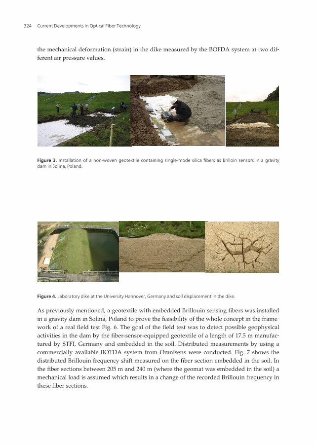
the mechanical deformation (strain) in the dike measured by the BOFDA system at two dif‐ferent air pressure values.
Figure 3. Installation of a non-woven geotextile containing single-mode silica fibers as Brilloin sensors in a gravitydam in Solina, Poland.
Figure 4. Laboratory dike at the University Hannover, Germany and soil displacement in the dike.
As previously mentioned, a geotextile with embedded Brillouin sensing fibers was installedin a gravity dam in Solina, Poland to prove the feasibility of the whole concept in the frame‐work of a real field test Fig. 6. The goal of the field test was to detect possible geophysicalactivities in the dam by the fiber-sensor-equipped geotextile of a length of 17.5 m manufac‐tured by STFI, Germany and embedded in the soil. Distributed measurements by using acommercially available BOTDA system from Omnisens were conducted. Fig. 7 shows thedistributed Brillouin frequency shift measured on the fiber section embedded in the soil. Inthe fiber sections between 205 m and 240 m (where the geomat was embedded in the soil) amechanical load is assumed which results in a change of the recorded Brillouin frequency inthese fiber sections.
Current Developments in Optical Fiber Technology324

Figure 5. Detection of a soil displacement (strain) in the laboratory dike shown in Fig. 4 using the BOFDA system.
Figure 6. Gravity dam in Solina, Poland (left) and the construction site with the sensor-based non-woven geotextilebefore embedding in the soil and 3 years later (right).
Smart Technical Textiles Based on Fiber Optic Sensorshttp://dx.doi.org/10.5772/54244
325

Figure 7. Distributed Brillouin frequency shift measured on the fiber section embedded in the soil (between 205 mand 240 m) 3 years after installation of the geomat.
With the objective of a cost-effective optimization of the BOFDA system a novel measure‐ment concept based on a digital signal processing has been realized[11]. This concept em‐ploys a novel digital data acquisition technique, which takes advantage of the reducedbandwidth required in BOFDA sensor systems. The backscattered optical signals can be dig‐itally sampled using state-of-the-art analog-to-digital converters and is processed off-line bymeans of modern digital signal processing methods, avoiding complex and expensive ana‐log components such as filters, oscillators and circuitry for signal analysis. The digital opti‐cal signal processing features several advantages compared to the measurement processusing NWA: less hardware is required, an increase of the dynamic range due to the offlinesignal processing and improvement of the data acquisition time is expected.
2.2. Monitoring of geotechnical structures using distributed POF OTDR sensorsembedded in geotextiles
To overcome the limit of silica-fiber-based distributed sensors, a novel distributed strainsensor based on low-priced standard POF and using the OTDR technique for monitoring ofmechanical deformations of geotechnical structures has been developed. Already publishedresults showed that it is possible to measure distributed strain in POF using the OTDR tech‐
Current Developments in Optical Fiber Technology326

nique[12]. In the framework of the German research project “Sensitive textile structures”(within the German program “ZUTECH” – “Future technologies”) and the European projectPOLYTECT further investigations of this effect with respect to the development of a new,distributed POF sensor embedded in technical textiles have been performed[6], [13].
The functional principle of the POF OTDR technique is very simple. An optical pulse islaunched into the fiber and the backscattered light mainly caused by Rayleigh scattering isrecorded as a function of time. The time interval from launching the pulse into the fiber untilthe return of the backscattered light (pulse response) depends linearly on the distance of thescattering location. The level of the backscattered light increases at locations where strain isapplied to the POF. Fig. 8 (left) shows the OTDR response of an unstretched POF (solid line)and of a stretched POF (broken line) which is stretched at about 42 m on a 1.4 m long sectionby 16 %. Fig. 8 (right) shows the relative change of scattering of the stretched POF section atdifferent strain values between 0 % and 16 % (calculated relative to the scattering of the un‐stretched fiber). The scattered light increases steadily with applied strain. Today, severalOTDR devices for POF are commercially available on the market. In the described investiga‐tions a photon counting OTDR device from Sunrise Luciol has been used. The device oper‐ates at 650 nm, has a dynamic range of 35 dB and allows a measurement of Rayleighscattering along a length of more than 100 m. The photon counting technique is ideal forachieving high dynamic range on very short sensing lengths. The two-point spatial resolu‐tion of the OTDR device is limited to 10 cm. An additional solution to evaluate the strain orlength change of a fiber section is to evaluate the shift of reflection peaks along the fiber (seeFig. 8, left). Such peaks originate for example from Fresnel reflections at the fiber end or fi‐ber connectors. This technique provides an absolute length change measurement with a res‐olution of up to 1.5 mm.
6
POF. Fig. 8 (left) shows the OTDR response of an unstretched POF (solid line) and of a stretched POF (broken line)
which is stretched at about 42 m on a 1.4 m long section by 16 %. Fig. 8 (right) shows the relative change of scattering of
the stretched POF section at different strain values between 0 % and 16 % (calculated relative to the scattering of the
unstretched fiber). The scattered light increases steadily with applied strain. Today, several OTDR devices for POF are
commercially available on the market. In the described investigations a photon counting OTDR device from Sunrise
Luciol has been used. The device operates at 650 nm, has a dynamic range of 35 dB and allows a measurement of
Rayleigh scattering along a length of more than 100 m. The photon counting technique is ideal for achieving high
dynamic range on very short sensing lengths. The two-point spatial resolution of the OTDR device is limited to 10 cm.
An additional solution to evaluate the strain or length change of a fiber section is to evaluate the shift of reflection peaks
along the fiber (see Fig. 8, left). Such peaks originate for example from Fresnel reflections at the fiber end or fiber
connectors. This technique provides an absolute length change measurement with a resolution of up to 1.5 mm.
Figure 8. Left: OTDR trace of POF in unstretched condition (solid line) and of POF with a stretched fiber section at about 42 m (broken line). Right: Change of the scattering along a 1.4 m long POF section that is stretched from 0 to 16 % in steps of 1 %.
Fig. 9 shows the increase of the scattered light versus applied strain. A non-linear dependence between the OTDR signal
(the backscattering) and the applied strain in the whole strain range was obtained. Strain of up to 45 % was measured
using standard PMMA POF.
Figure 9. Change of the backscattering as a function of strain measured on standard PMMA POF.
The attenuation of standard PMMA POF limits the distance range of distributed POF OTDR sensors to about 100 m.
Low-loss perfluorinated POF show a big potential as distributed strain sensors for long distances14. It has been shown
that using perfluorinated POF it is possible to monitor fiber lengths of more than 500 m (Fig. 10, left). Recent research
has demonstrated, that perfluorinated POF allow the measurement of very high strain values of up to 100 % (Fig. 10,
right).
Figure 8. Left: OTDR trace of POF in unstretched condition (solid line) and of POF with a stretched fiber section atabout 42 m (broken line). Right: Change of the scattering along a 1.4 m long POF section that is stretched from 0 to 16% in steps of 1 %.
Smart Technical Textiles Based on Fiber Optic Sensorshttp://dx.doi.org/10.5772/54244
327
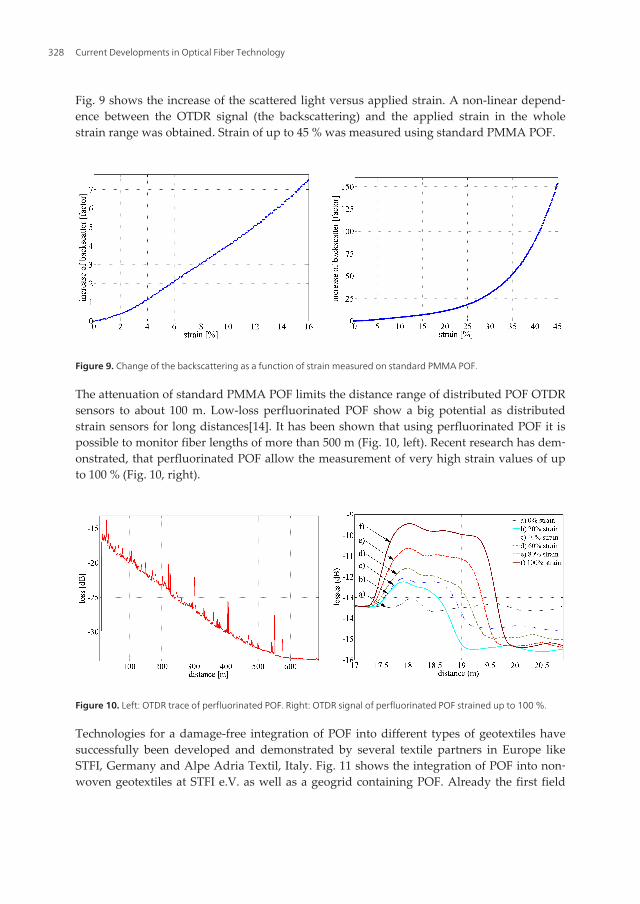
Fig. 9 shows the increase of the scattered light versus applied strain. A non-linear depend‐ence between the OTDR signal (the backscattering) and the applied strain in the wholestrain range was obtained. Strain of up to 45 % was measured using standard PMMA POF.
6
POF. Fig. 8 (left) shows the OTDR response of an unstretched POF (solid line) and of a stretched POF (broken line)
which is stretched at about 42 m on a 1.4 m long section by 16 %. Fig. 8 (right) shows the relative change of scattering of
the stretched POF section at different strain values between 0 % and 16 % (calculated relative to the scattering of the
unstretched fiber). The scattered light increases steadily with applied strain. Today, several OTDR devices for POF are
commercially available on the market. In the described investigations a photon counting OTDR device from Sunrise
Luciol has been used. The device operates at 650 nm, has a dynamic range of 35 dB and allows a measurement of
Rayleigh scattering along a length of more than 100 m. The photon counting technique is ideal for achieving high
dynamic range on very short sensing lengths. The two-point spatial resolution of the OTDR device is limited to 10 cm.
An additional solution to evaluate the strain or length change of a fiber section is to evaluate the shift of reflection peaks
along the fiber (see Fig. 8, left). Such peaks originate for example from Fresnel reflections at the fiber end or fiber
connectors. This technique provides an absolute length change measurement with a resolution of up to 1.5 mm.
Figure 8. Left: OTDR trace of POF in unstretched condition (solid line) and of POF with a stretched fiber section at about 42 m (broken line). Right: Change of the scattering along a 1.4 m long POF section that is stretched from 0 to 16 % in steps of 1 %.
Fig. 9 shows the increase of the scattered light versus applied strain. A non-linear dependence between the OTDR signal
(the backscattering) and the applied strain in the whole strain range was obtained. Strain of up to 45 % was measured
using standard PMMA POF.
Figure 9. Change of the backscattering as a function of strain measured on standard PMMA POF.
The attenuation of standard PMMA POF limits the distance range of distributed POF OTDR sensors to about 100 m.
Low-loss perfluorinated POF show a big potential as distributed strain sensors for long distances14. It has been shown
that using perfluorinated POF it is possible to monitor fiber lengths of more than 500 m (Fig. 10, left). Recent research
has demonstrated, that perfluorinated POF allow the measurement of very high strain values of up to 100 % (Fig. 10,
right).
Figure 9. Change of the backscattering as a function of strain measured on standard PMMA POF.
The attenuation of standard PMMA POF limits the distance range of distributed POF OTDRsensors to about 100 m. Low-loss perfluorinated POF show a big potential as distributedstrain sensors for long distances[14]. It has been shown that using perfluorinated POF it ispossible to monitor fiber lengths of more than 500 m (Fig. 10, left). Recent research has dem‐onstrated, that perfluorinated POF allow the measurement of very high strain values of upto 100 % (Fig. 10, right).
7
Figure 10. Left: OTDR trace of perfluorinated POF. Right: OTDR signal of perfluorinated POF strained up to 100 %.
Technologies for a damage-free integration of POF into different types of geotextiles have successfully been developed
and demonstrated by several textile partners in Europe like STFI, Germany and Alpe Adria Textil, Italy. Fig. 11 shows
the integration of POF into nonwoven geotextiles at STFI e.V. as well as a geogrid containing POF. Already the first
field tests proved that the POF-equipped geotextiles are suited for installation on construction sites. POF-based geomats
have successfully been installed in a railway embankment near Chemnitz, Germany (Fig. 12)6. All POF sensors have
survived the installation on construction site without any damage. Their functionality has been regularly tested (Fig. 12,
right).
Figure 11. Integration of POF into nonwoven geotextiles at STFI e.V. (left) and a geogrid containing POF (right).
Figure 12. Installation of POF-equipped geotextiles in a railway embankment near Chemnitz, Germany (left and middle) and OTDR traces measured on the textile-integrated POF (right).
During the last years, the POF-equipped geotextiles have successfully moved from the laboratory to the field.
Several field tests have successfully been conducted, e.g. in an open brown coal pit near Belchatow, Poland15. The
test was initiated, organized and supervised by Gloetzl Baumesstechnik GmbH, Germany in close cooperation with
Budokop, Poland and the owner of the coal pit. A sensor-equipped geogrid was installed directly on top of a
creeping slope. The 10 m long geogrid was manufactured by Alpe Adria Textil, Italy and comprised one standard
PMMA POF. Fig. 13 shows the installation of the sensor textile on top of the slope. It is covered with a 10 cm thick
sand layer. The textile is installed with the POF sensor bridging the cleft perpendicular to the opening. The geogrid
was installed in a slightly corrugated way simulating realistic installation conditions.
Figure 10. Left: OTDR trace of perfluorinated POF. Right: OTDR signal of perfluorinated POF strained up to 100 %.
Technologies for a damage-free integration of POF into different types of geotextiles havesuccessfully been developed and demonstrated by several textile partners in Europe likeSTFI, Germany and Alpe Adria Textil, Italy. Fig. 11 shows the integration of POF into non‐woven geotextiles at STFI e.V. as well as a geogrid containing POF. Already the first field
Current Developments in Optical Fiber Technology328

tests proved that the POF-equipped geotextiles are suited for installation on constructionsites. POF-based geomats have successfully been installed in a railway embankment nearChemnitz, Germany (Fig. 12)[6]. All POF sensors have survived the installation on construc‐tion site without any damage. Their functionality has been regularly tested (Fig. 12, right).
Figure 11. Integration of POF into nonwoven geotextiles at STFI e.V. (left) and a geogrid containing POF (right).
Figure 12. Installation of POF-equipped geotextiles in a railway embankment near Chemnitz, Germany (left and mid‐dle) and OTDR traces measured on the textile-integrated POF (right).
During the last years, the POF-equipped geotextiles have successfully moved from the labo‐ratory to the field. Several field tests have successfully been conducted, e.g. in an openbrown coal pit near Belchatow, Poland[15]. The test was initiated, organized and supervisedby Gloetzl Baumesstechnik GmbH, Germany in close cooperation with Budokop, Polandand the owner of the coal pit. A sensor-equipped geogrid was installed directly on top of acreeping slope. The 10 m long geogrid was manufactured by Alpe Adria Textil, Italy andcomprised one standard PMMA POF. Fig. 13 shows the installation of the sensor textile ontop of the slope. It is covered with a 10 cm thick sand layer. The textile is installed with thePOF sensor bridging the cleft perpendicular to the opening. The geogrid was installed in aslightly corrugated way simulating realistic installation conditions.
Smart Technical Textiles Based on Fiber Optic Sensorshttp://dx.doi.org/10.5772/54244
329

Figure 13. Installation of a geogrid containing PMMA POF at a creeping slope in a brown coal pit near Belchatow,Poland.
Measurements were conducted before and after installation. Fig. 14 (left) shows the OTDRtraces of the sensor fiber section (the magnitude of the backscatter increase relative to a refer‐ence measurement) in the middle of the textile where the fiber bridges the cleft. The figure clear‐ly shows a backscatter increase due to strain in the fiber at the position where the cleft wasopening. The high peak at about 35 m is caused by a very high and confined strain in the sensorfiber and textile. The magnitude of the backscatter increase corresponds to a maximum strain inthe fiber of more than 10 %. Such high strain values can only be measured by POF sensors. Silicafiber-based sensor systems would have failed at a strain exceeding about 1 %.
Due to the gradual increase of cleft width, the overlying textile and therefore the sensor fiberchange their absolute length. By evaluating the relative shift of the reflection peaks at bothends of the textile-integrated fiber, the values of the total elongation of the fiber sensor indi‐cating the width of the cleft was obtained. Fig. 14 (right) shows a relative linear increase ofthe POF length with time. The measurements indicate that the creep velocity of the slopewas constant during the time of observation with an average rate of about 2 mm per day.
Figure 14. POF OTDR traces at the position of the cleft (left) and total elongation of the POF obtained by a peak-shiftevaluation (right).
Current Developments in Optical Fiber Technology330

Recently, novel geogrids containing low-loss perfluorinated POF (PF POF) have been devel‐oped and manufactured by Alpe Adria Textil. Already the first field test has proved that thePF POF-equipped geotextiles are suited for installation on construction sites. PF POF-basedgeomats have successfully been installed at the creeping slope Kap Arkona at the GermanBaltic coast (Fig. 15, left). All PF POF sensors have survived the installation on constructionsite without any damage. At present, their functionality has been regularly tested by usingthe POF OTDR technique (Fig. 15, right).
9
Figure 15. Left: Installation of PF POF-equipped geotextiles at the creeping slope Kap Arkona at the German Baltic coast. Right: OTDR traces measured on the textile-integrated PF POF after installation.
The successful demonstration of the distributed POF OTDR sensors in the field and the huge interest of the geotechnical
industry in these sensors resulted in the development of the first commercially available product based on distributed
POF sensors – GEDISE: Distributed Sensor Technique in Geotextiles using POF (Fig. 16). GEDISE is commercially
available by Glötzl GmbH, Germany.
Figure 16. Leaflet of GEDISE: Distributed Sensor Technique in Geotextiles using POF (www.gloetzl.de).
2.3 Monitoring of masonry structures using distributed POF OTDR sensors embedded in technical textiles
The motivation to monitor masonry structures by sensor-equipped technical textiles is to strengthen the masonry
body and enhance the ductility of the structures and at the same time to monitor the structural health and detect any
damage of the structures, e.g. due to earthquakes. The development of sensor-based technical textiles containing
fiber optic sensors for the retrofitting of masonry structures is an innovative task of the European project
POLYTECT. The targeted applications are masonry and heritage structures that are structurally vulnerable, for
example in earthquake regions. Typical structural damages that have to be detected are vertical cracks. POF sensors
are very promising for that since they not only enable distributed strain measurement, they are also appropriate to
detect very short strained fiber sections of a few millimeters that will occur in case of cracks. For example, Fig. 17
shows the monitoring of a crack opening in a masonry structure using a POF OTDR sensor. A technical textile
containing POF was applied to the surface of the masonry sample6. Using the POF OTDR technique it was possible
to detect a crack opening of 1 mm and also the increase of the crack width up to 20 mm in steps of 2 mm (Fig. 17,
right).
Using the POF OTDR technique a field test was conducted on an one-storey brick building on a seismic shaking
table16. The test was organized and supervised by the Institute of Mechanics of Materials and Geostructures
(IMMG), Greece. Fig. 18 shows the POF sensors bonded to the wall with a cementitious resin matrix. The testing
procedure included several strong shocks, which resulted in structural damage of the building. The task of the
distributed POF sensors was to provide information about the existence and location of cracks in the structures. The
Figure 15. Left: Installation of PF POF-equipped geotextiles at the creeping slope Kap Arkona at the German Balticcoast. Right: OTDR traces measured on the textile-integrated PF POF after installation.
The successful demonstration of the distributed POF OTDR sensors in the field and the hugeinterest of the geotechnical industry in these sensors resulted in the development of the firstcommercially available product based on distributed POF sensors – GEDISE: DistributedSensor Technique in Geotextiles using POF (Fig. 16). GEDISE is commercially available byGlötzl GmbH, Germany.
Figure 16. Leaflet of GEDISE: Distributed Sensor Technique in Geotextiles using POF (www.gloetzl.de).
Smart Technical Textiles Based on Fiber Optic Sensorshttp://dx.doi.org/10.5772/54244
331
2.3. Monitoring of masonry structures using distributed POF OTDR sensors embedded intechnical textiles
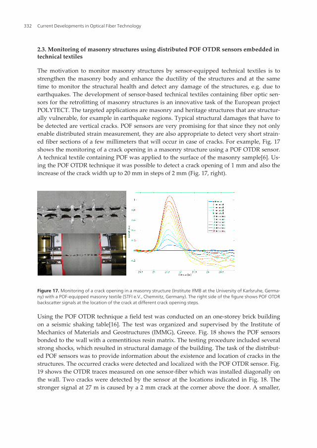
The motivation to monitor masonry structures by sensor-equipped technical textiles is tostrengthen the masonry body and enhance the ductility of the structures and at the sametime to monitor the structural health and detect any damage of the structures, e.g. due toearthquakes. The development of sensor-based technical textiles containing fiber optic sen‐sors for the retrofitting of masonry structures is an innovative task of the European projectPOLYTECT. The targeted applications are masonry and heritage structures that are structur‐ally vulnerable, for example in earthquake regions. Typical structural damages that have tobe detected are vertical cracks. POF sensors are very promising for that since they not onlyenable distributed strain measurement, they are also appropriate to detect very short strain‐ed fiber sections of a few millimeters that will occur in case of cracks. For example, Fig. 17shows the monitoring of a crack opening in a masonry structure using a POF OTDR sensor.A technical textile containing POF was applied to the surface of the masonry sample[6]. Us‐ing the POF OTDR technique it was possible to detect a crack opening of 1 mm and also theincrease of the crack width up to 20 mm in steps of 2 mm (Fig. 17, right).
Figure 17. Monitoring of a crack opening in a masonry structure (Institute IfMB at the University of Karlsruhe, Germa‐ny) with a POF-equipped masonry textile (STFI e.V., Chemnitz, Germany). The right side of the figure shows POF OTDRbackscatter signals at the location of the crack at different crack opening steps.
Using the POF OTDR technique a field test was conducted on an one-storey brick buildingon a seismic shaking table[16]. The test was organized and supervised by the Institute ofMechanics of Materials and Geostructures (IMMG), Greece. Fig. 18 shows the POF sensorsbonded to the wall with a cementitious resin matrix. The testing procedure included severalstrong shocks, which resulted in structural damage of the building. The task of the distribut‐ed POF sensors was to provide information about the existence and location of cracks in thestructures. The occurred cracks were detected and localized with the POF OTDR sensor. Fig.19 shows the OTDR traces measured on one sensor-fiber which was installed diagonally onthe wall. Two cracks were detected by the sensor at the locations indicated in Fig. 18. Thestronger signal at 27 m is caused by a 2 mm crack at the corner above the door. A smaller,
Current Developments in Optical Fiber Technology332

almost invisible crack has been detected at 150 cm distance from the first crack at the lowerright corner of the wall.
10
occurred cracks were detected and localized with the POF OTDR sensor. Fig. 19 shows the OTDR traces measured on one sensor-fiber which was installed diagonally on the wall. Two cracks were detected by the sensor at the locations indicated in Fig. 18. The stronger signal at 27 m is caused by a 2 mm crack at the corner above the door. A smaller, almost invisible crack has been detected at 150 cm distance from the first crack at the lower right corner of the wall.
Figure 17. Monitoring of a crack opening in a masonry structure (Institute IfMB at the University of Karlsruhe, Germany) with a POF-equipped masonry textile (STFI e.V., Chemnitz, Germany). The right side of the figure shows POF OTDR backscatter signals at the location of the crack at different crack opening steps.
Figure 18. Brick building on a shaking table with POF sensors installed horizontally and diagonally.
Figure 19. POF OTDR trace showing two cracks at 27.0 m and 28.5 m (left) and the corresponding first crack at 27.0 m of a
width of 2 mm (right).
During the last years, several field tests have successfully been conducted on real masonry buildings reinforced by POF-sensors-based technical textiles, one of them on a masonry house at the Eucentre in Pavia, Italy (Fig. 20). The testing
crack 1
POF sensor
crack 1
crack 2
POF sensors crack 1
crack 2
Figure 18. Brick building on a shaking table with POF sensors installed horizontally and diagonally.
10
occurred cracks were detected and localized with the POF OTDR sensor. Fig. 19 shows the OTDR traces measured on one sensor-fiber which was installed diagonally on the wall. Two cracks were detected by the sensor at the locations indicated in Fig. 18. The stronger signal at 27 m is caused by a 2 mm crack at the corner above the door. A smaller, almost invisible crack has been detected at 150 cm distance from the first crack at the lower right corner of the wall.
Figure 17. Monitoring of a crack opening in a masonry structure (Institute IfMB at the University of Karlsruhe, Germany) with a POF-equipped masonry textile (STFI e.V., Chemnitz, Germany). The right side of the figure shows POF OTDR backscatter signals at the location of the crack at different crack opening steps.
Figure 18. Brick building on a shaking table with POF sensors installed horizontally and diagonally.
Figure 19. POF OTDR trace showing two cracks at 27.0 m and 28.5 m (left) and the corresponding first crack at 27.0 m of a
width of 2 mm (right).
During the last years, several field tests have successfully been conducted on real masonry buildings reinforced by POF-sensors-based technical textiles, one of them on a masonry house at the Eucentre in Pavia, Italy (Fig. 20). The testing
crack 1
POF sensor
crack 1
crack 2
POF sensors crack 1
crack 2
Figure 19. POF OTDR trace showing two cracks at 27.0 m and 28.5 m (left) and the corresponding first crack at 27.0 mof a width of 2 mm (right).
During the last years, several field tests have successfully been conducted on real masonrybuildings reinforced by POF-sensors-based technical textiles, one of them on a masonryhouse at the Eucentre in Pavia, Italy (Fig. 20). The testing procedures of the textile-equippedmasonry building included several strong seismic shocks (simulating earthquakes) that re‐sulted in several cracks in the masonry walls. The occurred cracks were clearly detected andlocalized by the distributed POF OTDR sensor (Fig. 21) which demonstrated the potential ofthis technique to be used also for damage detection of masonry and heritage structures.
Smart Technical Textiles Based on Fiber Optic Sensorshttp://dx.doi.org/10.5772/54244
333

Figure 20. Application of technical textiles containing POF on a masonry building at the Eucentre in Pavia, Italy.
Figure 21. Detection of cracks in a masonry wall by a textile-embedded distributed POF OTDR sensor after several seis‐mic shocks applied to the building.
3. Medical textiles based on fiber optic sensors for healthcare monitoring
Healthcare monitoring of patients and old people who require a continuous medical assis‐tance and treatment is a subject of a number of research activities in Europe. In order to in‐crease the mobility of such patients, the development of wearable monitoring systems ableto measure important physiological parameters of the patients is targeted. Europe has con‐siderably pushed the developments of such wearable biomedical clothing containing differ‐ent types of sensors by a number of research projects.
The European project OFSETH (optical fiber sensors embedded into technical textile forhealthcare) supported by the 6th European framework program, has investigated how vari‐ous vital parameters such as respiratory movement, cardiac rate and pulse oxymetry can be
Current Developments in Optical Fiber Technology334

measured by fiber optic sensors based on silica and polymer optical fibers, embedded intomedical textiles. As a result, wearable solutions for healthcare monitoring, for patients re‐quiring a continuous medical assistance and treatment, are available. Despite of already ex‐isting electrical and also fiber optic sensors, OFSETH has achieved a breakthrough in thehealthcare monitoring by combining the advantages of pure fiber optic sensor technologiesand wearability of the textiles and so increasing the functionality of the sensor and the com‐fort of the system.
The OFSETH developments have targeted in the first place on the monitoring of sedated oranaesthetized patients under Medical Resonance Imaging (MRI)[17]. In this case electricalsensors cannot play a role; fiber optic sensors are advantageous because of their electromag‐netic compatibility. The use of fiber optic sensors instead of electrical sensors will reduce theelectromagnetic disturbance of the MRI field. Additionally, metallic parts and conductivewires of electrical sensors cause burns on the patient’s skin in the MRI field. Fiber optic sen‐sors are free from such metallic components and so burning hazard for the patients can beprevented. Besides, fiber optic sensors offer the advantage that the monitoring unit can beplaced out of the MRI field and can be connected to the sensor by a fiber cable of some fiveor ten meters.
Anaesthetized patients are usually transferred from the induction room to the MRI roomand back under anesthesia. A continuous monitoring of the patients from the induction tothe end of the anesthesia is required but in fact the medical staff usually uses different moni‐toring devices during the whole procedure, because the most standard monitoring devicesare not transportable or not MRI compatible. After the MRI examination, the patient is trans‐ferred back, still anesthetized, in the worst case without any monitoring system which putsthe patients at risk of anesthetic complications. Therefore, a transportable monitoring sys‐tem, able to follow the patients from the induction room to the MRI room and back withoutbeing removed is needed. The wearability of such a system will increase its functionalityand the comfort to the user. Wearable monitoring systems can also be used in the ambulato‐ry healthcare monitoring and the monitoring of Sudden Infant Death Syndrome. Therefore,OFSETH has mainly addressed the textile integration issues and in this context has extendedthe capability of wearable solutions for healthcare monitoring.
For MRI applications there is especially need to monitor the patients’ respiratory parame‐ters: respiratory movement and respiratory rate. Therefore, OFSETH has focused, amongother things, on the investigation of textile-integrated fiber optic sensors for respiratorymonitoring of patients during MRI examinations. For this purpose, medical textiles that in‐corporate silica and polymer optical fibers have been investigated where a wearable, adapt‐able and MRI compatible monitoring system has been targeted.
The feasibility of using fiber optic sensors for respiratory monitoring was demonstrated inthe past. It has been reported on fiber sensors woven into bandages or attached onto gar‐ments mainly using FBG (fiber Bragg gratings) and LPG (long period gratings) based on sili‐ca fibers[18], [19]. However, the poor compatibility of these sensors with industrial textileprocesses limits their flexibility and use for medical monitoring purposes.
Smart Technical Textiles Based on Fiber Optic Sensorshttp://dx.doi.org/10.5772/54244
335

Human breathing movement causes typical elongations of the abdominal circumference ofadults of up to 3 %. Using silica fibers, limited strain values of up to 1 % can be measured.Therefore, with a special focus on using POF instead of silica fibers, OFSETH has investigat‐ed different fiber sensor techniques for respiratory monitoring[20], [21]. A highly importantcriterion for selecting POF as medical sensor is its biocompatibility, especially in case of fiberbreakage.
3.1. POF OTDR sensor embedded in medical textiles for monitoring of the respiratorymovement
For the respiratory monitoring, there is an interest for the doctors to take information fromboth abdominal (for spontaneous ventilation) and thoracic (for intubated patients) move‐ment[17]. Therefore, a distributed measurement of the respiratory signal, using only onemonitor and one sensor fiber would be advantageous. Using an OTDR technique, it is possi‐ble to focus on a special part of the fiber and so to differentiate between abdominal andthoracic respiration. A distributed OTDR measurement makes possible to get only the re‐quired sensor information and to neglect loss contributions from non-sensing parts. In addi‐tion, an OTDR sensor system has the advantage of requiring only one fiber connection,which enables a quicker installation of the system on the patient.
A textile sample based on an elastic fabric containing a POF and manufactured by Centexbeland Elasta, Belgium was tested for the purposes of the respiratory movement monitoring bythe OTDR technique. Since it was difficult to integrate a straight optical fiber into an elasticfabric, the textile sample uses a special macrobending sensor design developed by Multitel,Belgium (Fig. 22)[21]. The textile is divided in two sections: a short elastic part of about 10cm whose length changes during the respiration and a longer non-elastic part. The POF isintegrated into the elastic section to measure the elongation of the fabric due to the respira‐tory movement of the thorax or abdomen. The macrobending sensor design (described moredetailed in Chapter 3.2) increases the sensitivity of the POF to the textile elongation andmakes possible to detect small changes in the amplitude of the respiratory movement by theOTDR technique. Macrobending effects in POF induce changes of the backscattering in thecorresponding area of the fiber that can be easily detected by the OTDR technique.
13
Fig. 22. Textile sample containing a POF and based on the macrobending sensor design (textile: Centexbel & Elasta, Belgium; sensor design: Multitel, Belgium).
The feasibility of measuring the respiratory waveform and rate in real time by the POF OTDR technique was demonstrated on a healthy adult during normal breathing21, 22. The textile sample was attached around the abdomen of the adult and the elastic part of the textile was placed in the area experiencing the most elongation due to the breathing movement (Fig. 23). The sensor signal was acquired by a fast OTDR device produced by Tempo (OFM20), which operates at 650 nm wavelength, allows a two-point spatial resolution of 5 cm and has a dynamic range of > 20 dB. The device makes possible to measure an OTDR trace in less than 1 s with a sufficient SNR. This acquisition time is fast enough to measure normal human breathing. The changes of the abdominal circumference due to the breathing movement were recorded simultaneously. Fig. 23 shows the result and demonstrates the high potential of the POF OTDR technique for the considered monitoring purposes.
Fig. 23. Monitoring of the respiratory abdominal movement of a human adult by POF OTDR sensor embedded in medical textiles (the OTDR sensor signal was compared with the signal measured by a spirometer).
3.2 Sensing harness for monitoring of the respiratory movement
Considering the influence of different patient’s morphology as well as textile integration issues to let free all vital organs for medical staff actions during incident or respiratory accidents, different fiber optic sensors have been integrated into a harness allowing an efficient handling and continuous measurement of the respiratory movement22. European norms in
Elastic fabric
Non-elastic fabric
Figure 22. Textile sample containing a POF and based on the macrobending sensor design (textile: Centexbel & Elasta,Belgium; sensor design: Multitel, Belgium).
Current Developments in Optical Fiber Technology336

The feasibility of measuring the respiratory waveform and rate in real time by the POFOTDR technique was demonstrated on a healthy adult during normal breathing[21], [22].The textile sample was attached around the abdomen of the adult and the elastic part of thetextile was placed in the area experiencing the most elongation due to the breathing move‐ment (Fig. 23). The sensor signal was acquired by a fast OTDR device produced by Tempo(OFM20), which operates at 650 nm wavelength, allows a two-point spatial resolution of 5cm and has a dynamic range of > 20 dB. The device makes possible to measure an OTDRtrace in less than 1 s with a sufficient SNR. This acquisition time is fast enough to measurenormal human breathing. The changes of the abdominal circumference due to the breathingmovement were recorded simultaneously. Fig. 23 shows the result and demonstrates thehigh potential of the POF OTDR technique for the considered monitoring purposes.
Figure 23. Monitoring of the respiratory abdominal movement of a human adult by POF OTDR sensor embedded inmedical textiles (the OTDR sensor signal was compared with the signal measured by a spirometer).
3.2. Sensing harness for monitoring of the respiratory movement
Considering the influence of different patient’s morphology as well as textile integration is‐sues to let free all vital organs for medical staff actions during incident or respiratory acci‐dents, different fiber optic sensors have been integrated into a harness allowing an efficienthandling and continuous measurement of the respiratory movement[22]. European normsin terms of textile and the medical specification have been taken into account for the designof the sensing harness where the fiber optic sensors are strategically placed for measurementof thoracic and abdominal movements caused by the breathing activity without corruption
Smart Technical Textiles Based on Fiber Optic Sensorshttp://dx.doi.org/10.5772/54244
337

of one signal by another (Fig. 24). This design is composed of adjustable parts in order to fitthe maximum of morphologies and to be worn both by men and women. The harness de‐sign keeps some places free, like the pre-cordium in order to facilitate resuscitation in case ofcardiac arrest or hemodynamical failure, and give vital information on hemodynamical sta‐tus during resuscitation. Access to the intra-venous infusion line has also been kept clear, foreasy access during anesthesia or for resuscitation purpose. It has been ensured that there isno pressure on venous or arterial blood vessels which could obstruct the regular blood flow.
Figure 24. Sensing harness containing fiber optic sensors for the monitoring of patients under MRI. A thoracic respira‐tion sensor is integrated in the black part (upper right); an abdominal respiration sensor is integrated in the white part(lower middle).
The elongation of the harness belt caused by the respiratory movement is measured usingdifferent fiber optic sensing principles based on FBGs and macrobending effects. The ab‐dominal movement causes elongations of about 1-3%, which is much higher than for thethoracic movement which causes only a fractional percentage change. Therefore an FBG sen‐sor which has high accuracy but a low strain limit is used for the thorax while for the abdo‐men a less accurate macrobending sensor is used which has a much higher strain limit.
The macrobending sensor developed by Multitel (Belgium) is based on bending effect of op‐tical fibers (Fig. 25, left)[22]. Bends cause light coupling from guided modes into radiationmodes and thus some power is lost. When the sensor textile is stretched, the curvature radi‐us increases, and the bending loss decreases. Therefore the intensity variations at the outputof the optical fiber will reflect the changes of the textile length, due to the respiratory move‐ment. Macrobending sensors have the advantages that their interrogation is very simple:they require measurement of intensity changes, so the main components needed are an LEDsource and a photodiode. Standard single-mode silica fibers have been integrated into elas‐tic fabrics, manufactured by Elasta (Belgium) during an industrial crochet fabrication proc‐ess. The bending textile design has the advantage that the integration of the optical fibers
Current Developments in Optical Fiber Technology338

into textiles is relatively simple. The bending design also ensures that the optical fiber is notdamaged at high strain during integration. Due to the relatively high amplitude of the ab‐dominal movement the signal-to-noise ratio is high enough to monitor the respiratory rate.
For the monitoring of the thoracic respiration movement an FBG sensor developed by Cen‐texbel (Belgium) and Multitel is used. Due to the FBG inscription process the fiber sensor isweakened, which reduces facilities for integration of the fiber into the textiles. For this rea‐son, only optical fibers with sufficient robustness should be used and conventional textilefabrication processes as opted for the macrobending sensor are inadequate for the FBG inte‐gration. The optical fiber containing the FBG was thus stitched directly onto an elastic fab‐ric[22]. The robustness of the sensor is guaranteed by an additional silicone coating andpolymer attachment points on both sides of the FBG are glued around the fiber for a betteradhesion of the sensor onto the fabric and easy stitching without impairing the sensor prop‐erties (Fig. 25, right).
Moulded attachment
Elasticbandage FBG sensor in a
moulded coating
Figure 25. Left: Design of the macrobending sensor. A silica optical fiber was embedded into an elastic fabric duringan industrial crochet fabrication process. Right: Design of the FBG sensor. A silica optical fiber containing an FBG wasstitched onto an elastic textile.
The harness based on the macrobending and FBG sensor was validated on a simulator inMRI environment[22]. A simulator based on a movable table was used (Fig. 26, left). Thedisplacement of the table was realized by a balloon connected to the medical respirator al‐lowing air-flow circulation by controlling the amplitude and frequency of the movementthrough the volume or air injected. The signals of the respirator, the fiber sensor responseand the gradient signals emitted by the MRI were measured in real-time. Several configura‐tions in terms of volume and/or frequency, in or out of the MRI tube and in presence of orwithout the MRI gradient were simulated and tested. As a result, it was demonstrated thatthe displacement of the movable table is detected in terms of amplitude and frequency. Thesignals of the fiber sensors were not degraded even when the system was submitted to thegradient of the MRI equipment in and out of the magnetic field (inside and outside the MRItube respectively), as shown in Fig. 26 (right, large picture). At the same time, a clinical vali‐dation of the system was carried out at a hospital of Lille, France on several healthy volun‐teers and patients of the hospital’s intensive care unit. Fig 26 (right, small picture) shows the
Smart Technical Textiles Based on Fiber Optic Sensorshttp://dx.doi.org/10.5772/54244
339

typical signal patterns for both thoracic and abdominal movement detected by the textile-embedded FBG and macrobending sensor on healthy adults.
Figure 26. Left: Set-up of the MRI-compatible simulator of CIC-IT de Nancy, France. Right, large picture: Test of theFBG sensor in MRI environment. The first two curves are related to the respiration simulator, the third curve shows theFBG sensor response and the last three curves are related to the magnetic gradients of the MRI equipment. Right,small picture: Abdominal and thoracic respiration signals detected by the textile-embedded macrobending and FBGsensor during a clinical test on healthy volunteers.
3.3. Fiber optic sensors for personal protective equipment
The European project i-Protect (intelligent PPE system for personnel in high-risk and com‐plex environments) develops an advanced personal protective equipment (PPE) system thatwill ensure active protection and information support for personnel operating in high-riskand complex environments in firefighting, chemical and mining rescue operations[23]. ThePPE system will be ergonomically designed and fully adapted to end-users’ needs as well asto working conditions. The core of the project is the development of advanced materials andsensors to be used for a multi-functional PPE. This includes a real-time monitoring of riskfactors (temperature, gas, oxygen level), users’ health status (body temperature, respiratoryrate, heart rate) and important protection parameters (end-of-service-life, air pressure incompressed units). The PPE will be wireless connected to a rescue command center.
For the monitoring of the users’ health status smart underwear containing fiber optic sen‐sors is being developed. Special attention is paid to the development of a heart rate sensor tobe used as a textile-integrated sensor in underwear. A first sensor prototype is based onmacrobending effects in POF[23]. The POF macrobending sensor is stitched onto an elasticfabric (the design is similar to this shown in Fig. 25, left) and measures the small elongationsof the textile which is caused by the heart movement. To increase the sensitivity of the sen‐sor, the cladding of the POF was treated[23]. A sensor belt containing the POF sensor wastested on a healthy volunteer to measure the circumference changes due to the heart move‐ment. The belt was wrapped around the chest of the volunteer close to the heart. Since thetextile design is also sensitive to the respiratory movement, the POF macrobending sensordetects both the respiratory and heart rate at the same time (Fig. 27). A signal processingshould be performed to filter the weak heart beats signals. It is expected that by using a
Current Developments in Optical Fiber Technology340

modified textile and sensor design it must be possible to improve the sensitivity of the POFmacrobending sensor to the heart movement. Alternatively, conventional monitoring techni‐ques like plethysmography could be adapted for the purpose of such applications.
Figure 27. Monitoring of the heart rate of a healthy volunteer by using a textile-embedded POF macrobending sen‐sor.
4. Conclusion
A number of research activities considering the development of novel smart technical tex‐tiles based on fiber optic sensors are running in Europe. Such smart technical textiles withembedded optical fibers are a potential new market niche for fiber optic sensors.
Several German projects and the European project POLYTECT have developed novel ge‐otextiles with embedded distributed Brillouin and POF OTDR sensors for monitoring ofgeotechnical and masonry structures, providing an alarm signal in case of structuraldamage. Particularly sensors based on POF take advantage of the high robustness, highelasticity and high break-down strain of POF allowing distributed sensing of strong me‐chanical deformations of soil and masonry walls. Multifunctional, smart technical textilesincorporating fiber optics sensors are a cost-effective solution to increase the structuralsafety of such structures. The breakthroughs include the use of such textiles for rein‐forcement and at the same time for monitoring of earthworks and masonry walls, givingonline information on the state and the performance of the structures and so preventinga total collapse. Such on-line and long-term monitoring systems will improve the chance
Smart Technical Textiles Based on Fiber Optic Sensorshttp://dx.doi.org/10.5772/54244
341

of an early detection and the location of “weak points” and damages, and will make itpossible to react rapidly and to control damages.
Novel monitoring systems based on medical textiles with embedded fiber optic sensors willbe used at medium-term in the healthcare monitoring and for personal protection of rescuesin high-risk environments where standard, non-optical monitoring systems show significantlimits. Such medical textiles containing fiber optic sensors have been developed in the Euro‐pean projects OFSETH and i-Protect for the monitoring of the respiratory movement of an‐aesthetized patients under MRI and for the monitoring of the health status of rescues.Especially for MRI applications where transportable and MRI compatible devices are need‐ed, pure fiber optic sensor solutions and the wearability of the textiles are advantageous.The design and comfort of such sensor systems will extend their use from hospitalization tothe ambulatory healthcare monitoring and homecare.
Acknowledgements
The research has been carried out in the framework of the German projects "SensorbasierteGeotextilien zur Deichertuechtigung” (FKZ 02WH0573) and “Sensitive Textilstrukturen”(AiF-Nr. 192 ZBG 1) as well as within the European projects POLYTECT (NMP2-CT-2006-026789), OFSETH (IST-2004-027869) and i-Protect (NMP2-SE-2010-229275). Theprojects have received research funding from the Federal Ministry of Education and Re‐search (BMBF), the Federal Ministry of Economics and Technology (BMWi) and the Europe‐an Commission within the European 6th and 7th Framework Programs. The authors arethankful for the financial support and the fruitful cooperation with the project partners.
Author details
Katerina Krebber
Federal Institute for Materials Research and Testing (BAM) Berlin, Germany
References
[1] “The future is Textiles”. Strategic Research Agenda of the European Technology Plat‐form for the future of textiles and clothing, EURATEX (2006).
[2] Lymberis, A. and A. Dittmar, A., “Advanced Wearable Health Systems and Applica‐tions”, IEEE Engineering in medicine and biology, pp. 29-33 (2007).
[3] Krebber, K., Lenke, P., Liehr, S., Witt, J. and Schukar, M., “Smart technical textileswith integrated POF sensors”, Proc. SPIE 6933, 69330V-1 – 69330V-15 (2008).
Current Developments in Optical Fiber Technology342

[4] Voet, M. R., Nances, A. and Vlekken, J., “Geodetect: a new step for the use of FibreBragg Grating technology in soil engineering”, Proc. of the 17th International Confer‐ence on Optical Fibre Sensors, 5855 (1), 214-217 (2005).
[5] Noether, N., Wosniok, A., Krebber, K. and Thiele, E., “A distributed fiber optic sen‐sor system for dike monitoring using Brillouin optical frequency domain analysis”,Proc. SPIE 6933, 69330T-1 – 69330T-9 (2008).
[6] Liehr, S., Lenke, P., Wendt, M., Krebber, K., Seeger, M., Thiele, E., Metschies, H., Ge‐breselassie, B. and Muenich, J. C., “Polymer Optical Fibre Sensor for DistributedStrain Measurement and Application in Structural Health Monitoring”, IEEE SensorsJ., 9 (11), 1330-1338 (2009).
[7] Kurashima, T., Horiguchi, T. and Tateda, M., “Distributed-temperature sensing us‐ing stimulated Brillouin scattering in optical silica fibers”, Optics Letters 15 (18),1038-1040 (1990).
[8] Bao, X., Webb, D.J. and Jackson, D.A., “32-km distributed temperature sensor basedon Brillouin loss in an optical fiber”, Optics Letters 18 (18), 1561-1563 (1993).
[9] Garus, D., Krebber, K., Schliep, F. and Gogolla, T., “Distributed sensing techniquebased on Brillouin optical-fiber frequency-domain analysis”, Optics Letters 21(17),1402-1404 (1996).
[10] Noether, N., Wosniok, A., Krebber, K. and Thiele, E., ”A Distributed fiber optic sen‐sor system for dike monitoring using Brillouin frequency domain analysis,” Proc.SPIE 7003, 700303 (2008).
[11] Noether, N., Wosniok, A., Krebber, K. and Thiele, E., “A distributed fiber-optic sen‐sor system for monitoring of large geotechnical strutures”, Proc. of the 4th Interna‐tional Conference on Structural Health Monitoring on Intelligent Infrastructure(SHMII-4) (2009).
[12] Husdi, I. R., Nakamura, K. and Ueha, S., ”Sensing characteristics of plastic optical fi‐bres measured by optical time-domain refelectometry”, Meas. Sci. Technol. 15,1553-1559 (2004).
[13] Lenke, P., Liehr, S. and Krebber, K., „Improvement of the distributed strain sensorbased on optical time domain reflectometry measurement in polymer optical fibers”,Proc. of the 17th International Conference on Plastic Optical Fibre, (2008).
[14] Liehr, S., Wendt, M., and Krebber, K., “Distributed strain measurement in perfluori‐nated polymer optical fibres using optical frequency domain reflectometry,” Meas‐urement Science and Technology 21(9), 094023–1 – 094023–6 (2010).
[15] Liehr, S., Lenke, P., Wendt, M., Krebber, K., Gloetzl, R., Schneider-Gloetzl, J., Gabino,L. and Krywult, L., „Distributed Polymer Optical Fiber Sensors in Geotextiles forMonitoring of Earthwork Strutures”, Proc. of the 4th International Conference onStructural Health Monitoring on Intelligent Infrastructure (SHMII-4) (2009).
Smart Technical Textiles Based on Fiber Optic Sensorshttp://dx.doi.org/10.5772/54244
343

[16] Liehr, S., Wendt, M., Krebber, Muenich, J. C., Stempniewski, L. and Metschies, H.,„Distributed polymer optical fiber sensors integrated in technical textiles for moni‐toring of masonry structures”, Proc. of the 4th International Conference on StructuralHealth Monitoring on Intelligent Infrastructure (SHMII-4) (2009).
[17] De jonckheere, J., Jeanne, M., Grillet, A., Weber, S., Chaud, P., Logier, R. and Weber,J. L., “OFSETH: Optical Fibre Embedded into technical Textile for Healthcare, an effi‐cient way to monitor patient under magnetic resonance imaging”, Proc. IEEE EMBCconference Engineering in Medicine and Biology Society (2007).
[18] Wehrle, G., Nohama, P., Kalinowski, H.J., Torres, P.I. and Valente, L.C.G., “A fibreoptic Bragg grating strain sensor for monitoring ventilatory movements”, Meas. Sci.Technol. 12, 805-809 (2001).
[19] Allsop, T., Revees, R., Webb, D. J. and Bennion, I., “Respiratory monitoring using fi‐bre long period grating sensors”, Novel Optical Instrumentation for Biomedical Ap‐plications II, SPIE-OSA Biomedical Optics, SPIE 5864, Q1-Q6 (2005).
[20] Grillet, A., Kinet, D., Witt, J., Schukar, M., Krebber, K., Pirotte, F. and Depré, A., “Op‐tical Fiber Sensors Embedded into Medical Textiles for Healthcare Monitoring”, IEEESensors J., 8 (7), 1215-1222 (2008).
[21] Krebber, K., Grillet, A., Witt, J., Schukar, M., Kinet, D., Thiel, T., Pirotte, F. and Depré,A., “Optical fibre sensors embedded into technical textile for healthcare (OFSETH)”,Proc. of the 16th International Conference on Plastic Optical Fibre, 227-233 (2007).
[22] Witt, J., Narbonneau, F., Schukar, M., Krebber, K., De Jonckheere, J., Jeanne, M., Ki‐net, D., Paquet, B., Depré, A., D´Angelo, L.T., Thiel, T. and Logier, R., “Medical tex‐tiles with embedded fiber optic sensors for monitoring of respiratory movement”,IEEE Sensors J., 12 (1), 246-254 (2012).
[23] Witt, J., Krebber, K., Demuth, J. and Sasek, L., “Fiber optic heart rate sensor for inte‐gration into personal protective equipment”, Proc. of International Workshop Bio‐Photonics 2011, Th6.26, 1-3 (2011).
Current Developments in Optical Fiber Technology344