Embed Size (px)
Citation preview
Small Cell and Indoor Cables for 5G
800-867-2629
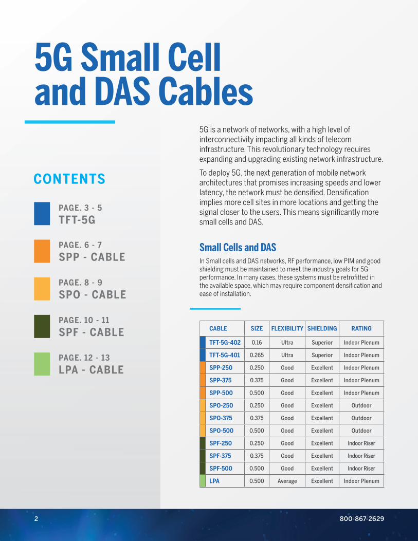
5G is a network of networks, with a high level of interconnectivity impacting all kinds of telecom infrastructure. This revolutionary technology requires expanding and upgrading existing network infrastructure.
To deploy 5G, the next generation of mobile network architectures that promises increasing speeds and lower latency, the network must be densified. Densification implies more cell sites in more locations and getting the signal closer to the users. This means significantly more small cells and DAS.
Small Cells and DASIn Small cells and DAS networks, RF performance, low PIM and good shielding must be maintained to meet the industry goals for 5G performance. In many cases, these systems must be retrofitted in the available space, which may require component densification and ease of installation.
CABLE SIZE FLEXIBILITY SHIELDING RATING
TFT-5G-402 0.16 Ultra Superior Indoor Plenum
TFT-5G-401 0.265 Ultra Superior Indoor Plenum
SPP-250 0.250 Good Excellent Indoor Plenum
SPP-375 0.375 Good Excellent Indoor Plenum
SPP-500 0.500 Good Excellent Indoor Plenum
SPO-250 0.250 Good Excellent Outdoor
SPO-375 0.375 Good Excellent Outdoor
SPO-500 0.500 Good Excellent Outdoor
SPF-250 0.250 Good Excellent Indoor Riser
SPF-375 0.375 Good Excellent Indoor Riser
SPF-500 0.500 Good Excellent Indoor Riser
LPA 0.500 Average Excellent Indoor Plenum
5G Small Cell and DAS Cables
CONTENTS
PAGE. 3 - 5
TFT-5G
PAGE. 6 - 7
SPP - CABLE
PAGE. 8 - 9
SPO - CABLE
PAGE. 10 - 11
SPF - CABLE
PAGE. 12 - 13
LPA - CABLE
2
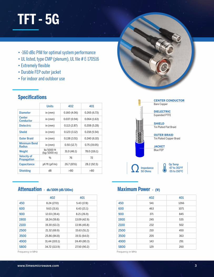
• -160 dBc PIM for optimal system performance• UL listed, type CMP (plenum), UL file # E-170516• Extremely flexible• Durable FEP outer jacket• For indoor and outdoor use
Specifications
Attenuation - db/100ft (dB/100m) Maximum Power - (W)
Units 402 401
Diameter in (mm) 0.160 (4.06) 0.265 (6.73)
Center Conductor in (mm) 0.037 (0.94) 0.064 (1.63)
Dielectric in (mm) 0.113 (2.87) 0.208 (5.28)
Sheild in (mm) 0.123 (3.12) 0.218 (5.54)
Outer Braid in (mm) 0.138 (3.51) 0.240 (6.10)
Minimum Bend Radius in (mm) 0.50 (12.7) 0.75 (19.05)
Weight lb/1000 ft (kg/1000 m) 31.0 (46.1) 78.0 (116.1)
Velocity of Propagation % 76 72
Capacitance pF/ft (pF/m) 26.7 (87.6) 28.2 (92.5)
Shielding dB >80 >80
402 401
450 8.24 (27.0) 5.43 (17.8)
600 9.63 (31.6) 6.43 (21.1)
900 12.03 (39.4) 8.21 (26.9)
1900 18.24 (59.8) 13.09 (42.9)
2100 19.30 (63.3) 13.96 (45.8)
2500 21.32 (69.9) 15.63 (51.2)
3500 25.86 (84.8) 19.51 (64.0)
4900 31.44 (103.1) 24.49 (80.3)
5800 34.72 (113.9) 27.50 (90.2)
402 401
450 541 1266
600 463 1071
900 371 845
1900 245 535
2100 232 502
2500 210 450
3500 205 363
4900 143 291
5800 129 260
Op Temp-67 to 302ºF-55 to 150ºC
Impedance50 Ohms
DIELECTRIC Expanded PTFE
OUTER BRAID Tin Plated Copper Braid
JACKETBlue FEP
CENTER CONDUCTORBare Copper
SHIELD Tin Plated Flat Braid
3www.timesmicrowave.com
Frequency in MHz Frequency in MHz
TFT - 5G

TFT - 5G
800-867-26294
Code Description
10M 1.0/2.3 mini DIN Male
225F 2.2/5 Female (jack)
225M 2.2/5 Male (plug)
41F 4.1/9.5 mini DIN Female
41M 4.1/9.5 mini DIN Male
43F 4.3/10 Female (jack)
43FB 4.3/10 Female (jack) bulkhead
43M 4.3/10 Male (plug)
43MR 4.3/10 Male (plug) right angle
43MS 4.3/10 Male (plug) snap-on
DF 7/16 Female (jack)
DFP 7/16-Female (jack) panel mount
DM 7/16-Male (plug)
DMR 7/16-Male (plug) right angle
NF N-Female (jack)
NFB N-Female (jack) bulkhead
NM N-Male (plug)
NMR N-Male (plug) right angle
NXFB Nex10 Female (jack) bulkhead
NXM Nex10 Male (plug)
NXMR Nex10 Male (plug) right angle
QM QMA-Male (plug)
QMR QMA-Male (plug) right angle
SM SMA-Male (plug)
SMR SMA-Male (plug) right angle
USE CODES FROM THE CHART BELOW.
How to order
T F T 4 0 2 - C O D E C O D E - 1 0 . 0 F
- Connector A Connector B - Length / 3 dig F = feetM = metersI = inches
Code Description Weather Boot - WPB (Y/N) See page 13 for details
225M 2.2/5 Male (plug) N
41F 4.1/9.5 mini DIN Female N
41MR 4.1/9.5 mini DIN Male right angle Y
43F 4.3/10 Female (jack) N
43FB 4.3/10 Female (jack) bulkhead N
43M 4.3/10 Male (plug) Y
43MR 4.3/10 Male (plug) right angle Y
43MS 4.3/10 Male (plug) snap-on Y
DF 7/16 DIN female (jack) N
DM 7/16 DIN Male (plug) Y
DMR 7/16 DIN Male (plug) right angle Y
NFB N-Female (jack) bulkhead N
NF N-Female (jack) N
NM N-Male (plug) Y
NMR N-Male (plug) right angle Y
NXFB Nex10 Female (jack) bulkhead N
NXM Nex10 Male (plug) Y
NXMS Nex10 Male (plug) snap-on Y
NXMR Nex10 Male (plug) right angle N
QM QMA-Male (plug) N
QMR QMA-Male (plug) right angle N
SM SMA-Male (plug) N
SMR SMA-Male (plug) right angle N
5www.timesmicrowave.com
USE CODES FROM THE CHART BELOW.
How to order
T F T 4 0 1 - C O D E C O D E - 1 0 . 0 F
- Connector A Connector B - Length / 3 dig F = feetM = metersI = inches
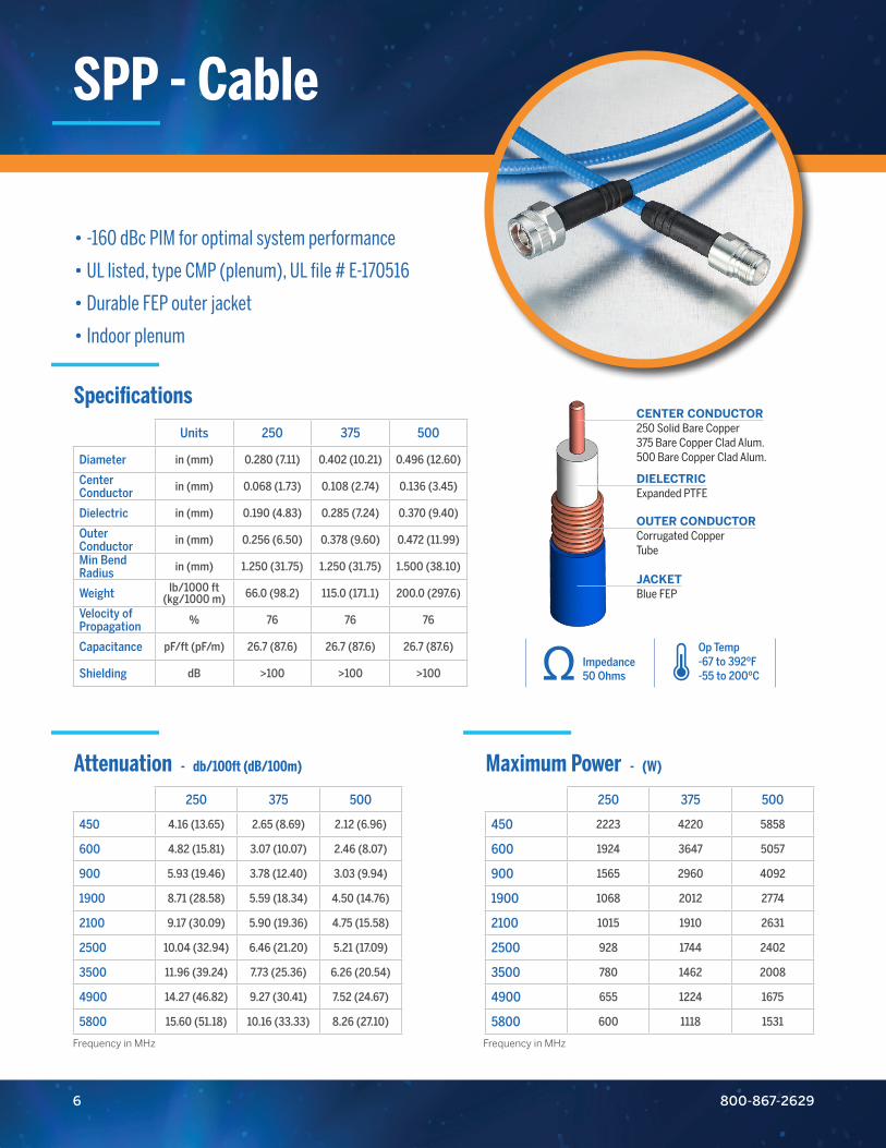
• -160 dBc PIM for optimal system performance
• UL listed, type CMP (plenum), UL file # E-170516
• Durable FEP outer jacket
• Indoor plenum
SPP - Cable
Specifications
Attenuation - db/100ft (dB/100m) Maximum Power - (W)
Units 250 375 500
Diameter in (mm) 0.280 (7.11) 0.402 (10.21) 0.496 (12.60)
Center Conductor in (mm) 0.068 (1.73) 0.108 (2.74) 0.136 (3.45)
Dielectric in (mm) 0.190 (4.83) 0.285 (7.24) 0.370 (9.40)
Outer Conductor in (mm) 0.256 (6.50) 0.378 (9.60) 0.472 (11.99)
Min Bend Radius in (mm) 1.250 (31.75) 1.250 (31.75) 1.500 (38.10)
Weight lb/1000 ft (kg/1000 m) 66.0 (98.2) 115.0 (171.1) 200.0 (297.6)
Velocity of Propagation % 76 76 76
Capacitance pF/ft (pF/m) 26.7 (87.6) 26.7 (87.6) 26.7 (87.6)
Shielding dB >100 >100 >100
250 375 500
450 4.16 (13.65) 2.65 (8.69) 2.12 (6.96)
600 4.82 (15.81) 3.07 (10.07) 2.46 (8.07)
900 5.93 (19.46) 3.78 (12.40) 3.03 (9.94)
1900 8.71 (28.58) 5.59 (18.34) 4.50 (14.76)
2100 9.17 (30.09) 5.90 (19.36) 4.75 (15.58)
2500 10.04 (32.94) 6.46 (21.20) 5.21 (17.09)
3500 11.96 (39.24) 7.73 (25.36) 6.26 (20.54)
4900 14.27 (46.82) 9.27 (30.41) 7.52 (24.67)
5800 15.60 (51.18) 10.16 (33.33) 8.26 (27.10)
250 375 500
450 2223 4220 5858
600 1924 3647 5057
900 1565 2960 4092
1900 1068 2012 2774
2100 1015 1910 2631
2500 928 1744 2402
3500 780 1462 2008
4900 655 1224 1675
5800 600 1118 1531
Op Temp-67 to 392ºF-55 to 200ºC
Impedance50 Ohms
DIELECTRIC Expanded PTFE
OUTER CONDUCTOR Corrugated CopperTube
JACKETBlue FEP
CENTER CONDUCTOR250 Solid Bare Copper375 Bare Copper Clad Alum.500 Bare Copper Clad Alum.
800-867-26296
Frequency in MHz Frequency in MHz
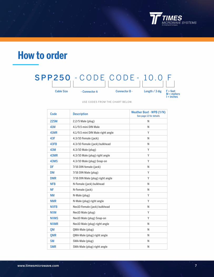
Code Description Weather Boot - WPB (Y/N) See page 13 for details
225M 2.2/5 Male (plug) N
41M 4.1/9.5 mini DIN Male N
41MR 4.1/9.5 mini DIN Male right angle Y
43F 4.3/10 Female (jack) N
43FB 4.3/10 Female (jack) bulkhead N
43M 4.3/10 Male (plug) Y
43MR 4.3/10 Male (plug) right angle Y
43MS 4.3/10 Male (plug) Snap-on Y
DF 7/16 DIN female (jack) N
DM 7/16 DIN Male (plug) Y
DMR 7/16 DIN Male (plug) right angle Y
NFB N-Female (jack) bulkhead N
NF N-Female (jack) N
NM N-Male (plug) Y
NMR N-Male (plug) right angle Y
NXFB Nex10 Female (jack) bulkhead N
NXM Nex10 Male (plug) Y
NXMS Nex10 Male (plug) Snap-on Y
NXMR Nex10 Male (plug) right angle N
QM QMA-Male (plug) N
QMR QMA-Male (plug) right angle N
SM SMA-Male (plug) N
SMR SMA-Male (plug) right angle N
7www.timesmicrowave.com
USE CODES FROM THE CHART BELOW.
How to order
S P P 2 5 0 - C O D E C O D E - 1 0 . 0 F
Cable Size Connector B -- Connector A Length / 3 dig F = feetM = metersI = inches
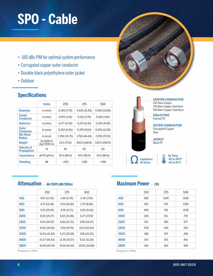
• -160 dBc PIM for optimal system performance
• Corrugated copper outer conductor
• Durable black polyethylene outer jacket
• Outdoor
SPO - Cable
Specifications
Attenuation - db/100ft (dB/100m) Maximum Power - (W)
Units 250 375 500
Diameter in (mm) 0.303 (7.70) 0.435 (11.05) 0.545 (13.84)
Center Conductor in (mm) 0.075 (1.91) 0.110 (2.79) 0.142 (3.61)
Dielectric in (mm) 0.177 (4.50) 0.272 (6.91) 0.354 (8.99)
Outer Conductor in (mm) 0.252 (6.40) 0.378 (9.60) 0.476 (12.09)
Min Bend Radius in (mm) 1.250 (31.75) 1.750 (44.45) 2.250 (57.15)
Weight lb/1000 ft (kg/1000 m) 51.0 (75.9) 100.0 (148.8) 135.0 (200.9)
Velocity of Propagation % 83 83 83
Capacitance pF/ft (pF/m) 24.5 (80.4) 24.5 (80.4) 24.5 (80.4)
Shielding dB >100 >100 >100
250 375 500
450 4.07 (13.35) 2.85 (9.35) 2.30 (7.55)
600 4.75 (15.58) 3.34 (10.96) 2.70 (8.86)
900 5.91 (19.39) 4.18 (13.71) 3.40 (11.16)
1900 8.92 (29.27) 6.42 (21.06) 5.27 (17.29)
2100 9.44 (30.97) 6.80 (22.31) 5.60 (18.37)
2500 10.41 (34.16) 7.54 (24.74) 6.23 (20.44)
3500 12.63 (41.44) 9.23 (30.28) 7.68 (25.20)
4900 15.37 (50.43) 11.36 (37.27) 9.52 (31.24)
5800 16.99 (55.74) 12.62 (41.41) 10.63 (34.88)
250 375 500
450 580 1140 1636
600 497 975 1396
900 400 781 1108
1900 266 511 719
2100 251 482 677
2500 228 436 610
3500 188 357 496
4900 155 291 401
5800 140 262 360
800-867-26298
Frequency in MHz Frequency in MHz
DIELECTRIC Foamed PE
OUTER CONDUCTOR Corrugated CopperTube
JACKETBlack PE
CENTER CONDUCTOR250 Bare Copper375 Bare Copper Clad Alum500 Bare Copper Clad Alum
Op Temp-40 to 185ºF-40 to 85ºC
Impedance50 Ohms
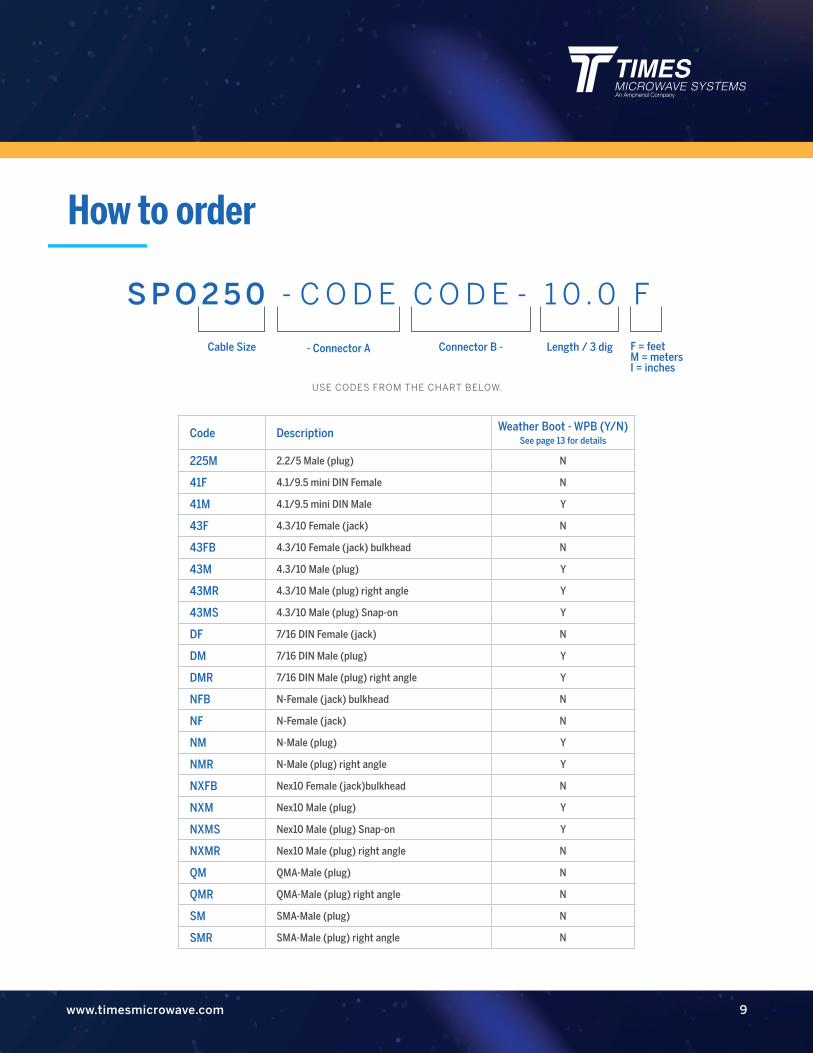
Code Description Weather Boot - WPB (Y/N) See page 13 for details
225M 2.2/5 Male (plug) N
41F 4.1/9.5 mini DIN Female N
41M 4.1/9.5 mini DIN Male Y
43F 4.3/10 Female (jack) N
43FB 4.3/10 Female (jack) bulkhead N
43M 4.3/10 Male (plug) Y
43MR 4.3/10 Male (plug) right angle Y
43MS 4.3/10 Male (plug) Snap-on Y
DF 7/16 DIN Female (jack) N
DM 7/16 DIN Male (plug) Y
DMR 7/16 DIN Male (plug) right angle Y
NFB N-Female (jack) bulkhead N
NF N-Female (jack) N
NM N-Male (plug) Y
NMR N-Male (plug) right angle Y
NXFB Nex10 Female (jack)bulkhead N
NXM Nex10 Male (plug) Y
NXMS Nex10 Male (plug) Snap-on Y
NXMR Nex10 Male (plug) right angle N
QM QMA-Male (plug) N
QMR QMA-Male (plug) right angle N
SM SMA-Male (plug) N
SMR SMA-Male (plug) right angle N
9www.timesmicrowave.com
USE CODES FROM THE CHART BELOW.
How to order
S P O 2 5 0 - C O D E C O D E - 1 0 . 0 F
Cable Size Connector B -- Connector A Length / 3 dig F = feetM = metersI = inches
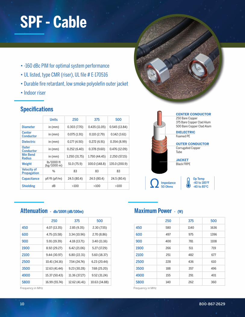
• -160 dBc PIM for optimal system performance
• UL listed, type CMR (riser), UL file # E-170516
• Durable fire retardant, low smoke polyolefin outer jacket
• Indoor riser
SPF - Cable
Specifications
Attenuation - db/100ft (dB/100m) Maximum Power - (W)
Units 250 375 500
Diameter in (mm) 0.303 (7.70) 0.435 (11.05) 0.545 (13.84)
Center Conductor in (mm) 0.075 (1.91) 0.110 (2.79) 0.142 (3.61)
Dielectric in (mm) 0.177 (4.50) 0.272 (6.91) 0.354 (8.99)
Outer Conductor in (mm) 0.252 (6.40) 0.378 (9.60) 0.476 (12.09)
Min Bend Radius in (mm) 1.250 (31.75) 1.750 (44.45) 2.250 (57.15)
Weight lb/1000 ft (kg/1000 m) 51.0 (75.9) 100.0 (148.8) 135.0 (200.9)
Velocity of Propagation % 83 83 83
Capacitance pF/ft (pF/m) 24.5 (80.4) 24.5 (80.4) 24.5 (80.4)
Shielding dB >100 >100 >100
250 375 500
450 4.07 (13.35) 2.85 (9.35) 2.30 (7.55)
600 4.75 (15.58) 3.34 (10.96) 2.70 (8.86)
900 5.91 (19.39) 4.18 (13.71) 3.40 (11.16)
1900 8.92 (29.27) 6.42 (21.06) 5.27 (17.29)
2100 9.44 (30.97) 6.80 (22.31) 5.60 (18.37)
2500 10.41 (34.16) 7.54 (24.74) 6.23 (20.44)
3500 12.63 (41.44) 9.23 (30.28) 7.68 (25.20)
4900 15.37 (50.43) 11.36 (37.27) 9.52 (31.24)
5800 16.99 (55.74) 12.62 (41.41) 10.63 (34.88)
250 375 500
450 580 1140 1636
600 497 975 1396
900 400 781 1108
1900 266 511 719
2100 251 482 677
2500 228 436 610
3500 188 357 496
4900 155 291 401
5800 140 262 360
Op Temp-40 to 185ºF-40 to 85ºC
Impedance50 Ohms
DIELECTRIC Foamed PE
OUTER CONDUCTOR Corrugated CopperTube
JACKETBlack FRPE
CENTER CONDUCTOR250 Bare Copper375 Bare Copper Clad Alum500 Bare Copper Clad Alum
800-867-262910
Frequency in MHz Frequency in MHz

Code Description Weather Boot - WPB (Y/N) See page 13 for details
225M 2.2/5 Male(plug) N
41M 4.1/9.5 mini DIN Male N
41MR 4.1/9.5 mini DIN Male right angle Y
43F 4.3/10 Female (jack) N
43FB 4.3/10 Female (jack) bulkhead N
43M 4.3/10 Male (plug) Y
43MR 4.3/10 Male (plug) right angle Y
43MS 4.3/10 Male (plug) Snap-on Y
DF 7/16 DIN female (jack) N
DM 7/16 DIN Male (plug) Y
DMR 7/16 DIN Male (plug) right angle Y
NFB N-Female (jack) bulkhead N
NF N-Female (jack) N
NM N-Male (plug) Y
NMR N-Male (plug) right angle Y
NXFB Nex10 Female(jack)bulkhead N
NXM Nex10 Male(plug) Y
NXMS Nex10 Male(plug) snap-on Y
NXMR Nex10 Male(plug) right angle N
QM QMA-Male (plug) N
QMR QMA-Male (plug)right angle N
SM SMA-Male (plug) N
SMR SMA-Male (plug) right angle N
11www.timesmicrowave.com
USE CODES FROM THE CHART BELOW.
How to order
S P F 2 5 0 - C O D E C O D E - 1 0 . 0 F
- Connector ACable Size Connector B - Length / 3 dig F = feetM = metersI = inches

• Listed type CMP plenum cable
• Low loss indoor plenum feeder cable
• Excellent shielding effectiveness
• Outstanding intermodulation performance
• Indoor plenum
Specifications
Attenuation - db/100ft (dB/100m) Maximum Power - (W)
Units 250
Diameter in (mm) 0.620 (15.75)
Center Conductor in (mm) 0.189 (4.80)
Dielectric in (mm) 0.469 (11.9)
Outer Conductor in (mm) 0.539 (13.6)
Min Bend Radius in (mm) 5.0 (127)
Weight lb/1000 ft (kg/1000 m) 163.3 (243.0)
Velocity of Propagation % 86
Capacitance pF/ft (pF/m) 23.6 (77.4)
Shielding dB >100
450 1.73 (5.68)
600 2.03 (6.66)
900 2.56 (8.40)
1900 3.97 (13.03)
2100 4.22 (13.85)
2500 4.70 (15.42)
3500 5.80 (19.03)
4900 7.19 (23.59)
5800 8.03 (26.35)
450 2366
600 2013
900 1606
1900 1037
2100 978
2500 879
3500 715
4900 578
5800 518
Op Temp14 to 167ºF-10 to 75ºC
Impedance50 Ohms
DIELECTRIC AIR SPACED Polyethylene
OUTER CONDUCTOR Corrugated Copper
JACKETRed FR-PVC
CENTER CONDUCTORCopper Clad Aluminum
800-867-262912
LPA 1/2” Plenum
Frequency in MHz Frequency in MHz
P/N: LPA-500

Available Connectors
Stock Code Interface Part Number
3190 - 6344 N-Male EZ-LP500-NMC-LP
3190 - 6857 N-Male-RA EZ-LP500-NMC-RA-LP
3190 - 6346 4.3-10 Male EZ-LP500-4310MC-LP
3190 - 6350 7-16M EZ-LP-500-716MC-LP
3190 - 6799 N-Female EZ-LP-500-NFC-LP
www.timesmicrowave.com 13
LPA Connectors and Installation Tools
FT-540 Flaring ToolUsed for flaring the outer sheath once the back nut has been installed on the cable. Part number: FT-540.
ST-LPA-500 Installation ToolAll in one prep tool for the LPA-500-LLPL. Can be used by hand or drill mounted. Part Number: ST-LPA-500.

Times Microwave Systems358 Hall Avenue
Wallingford, CT 06492
USA
T 800. 867.2629
F 203. 949.8423