Embed Size (px)
Citation preview

M e r c e d e s - B e n z S L R M c L a r e n .O p e r a t o r ’ s M a n u a l .
Mer
cede
s-B
enz
SLR
McL
aren
Ope
rato
r’s
Man
ual
Mercedes-Benz SLR McLaren. Operator ’s Manual .

SLR. UNLIMITED.

Thank you for choosing Mercedes-Benz
Our company and staff congratulate you on the purchase of your new Mercedes-Benz SLR McLaren.
Your selection of our product is a demonstration of your trust in our company name. Furthermore, it exemplifies your desire to own
an automobile that will be as easy as possible to operate and provide years of service.
Should you have any questions, please contact your dealer contact for your Mercedes-Benz SLR McLaren or call us at
1-800-FOR-MERCedes (in the USA) or 1-888-881-6611 (in Canada). Your dealer contact will co-ordinate appointments for servicing of
your vehicle and clarify any issues arising from the use of your Mercedes-Benz SLR McLaren.
Your Mercedes-Benz represents the efforts of many skilled engineers and craftsmen. To help assure your driving pleasure, and also
the safety of you and your passengers, we ask you to make a small investment of time:
� Please read this manual carefully, then return it to your vehicle where it will be handy for your reference.
� Please follow the recommendations contained in this manual. They are designed to acquaint you with the operation of your
Mercedes-Benz SLR McLaren.
� Please pay attention to the warnings and cautions contained in this manual. They are designed to help improve the safety of the
vehicle operator and occupants.
We extend our best wishes for many miles of safe, pleasurable driving.
Mercedes-Benz USA, LLC
A DaimlerChrysler Company

Contents
Contents
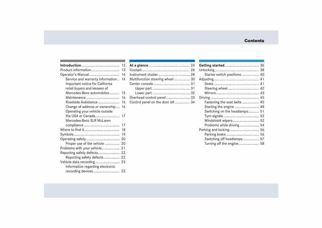
Introduction ....................................... 12Product information............................. 13Operator’s Manual ............................... 14
Service and warranty information .. 14Important notice for California retail buyers and lessees of Mercedes-Benz automobiles .......... 15Maintenance .................................. 16Roadside Assistance ...................... 16Change of address or ownership.... 16Operating your vehicle outside the USA or Canada......................... 17Mercedes-Benz SLR McLaren compliance .................................... 17
Where to find it .................................... 18Symbols............................................... 19Operating safety .................................. 20
Proper use of the vehicle ............... 20Problems with your vehicle.................. 21Reporting safety defects...................... 22
Reporting safety defects ................ 22Vehicle data recording......................... 23
Information regarding electronic recording devices........................... 23
At a glance .......................................... 24Cockpit................................................. 26Instrument cluster ................................ 28Multifunction steering wheel ................ 30Center console ..................................... 31
Upper part ...................................... 31Lower part ...................................... 32
Overhead control panel ........................ 33Control panel on the door sill ............... 34
Getting started ................................... 36Unlocking ............................................. 38
Starter switch positions.................. 40Adjusting .............................................. 41
Seats .............................................. 41Steering wheel................................ 42Mirrors............................................ 43
Driving.................................................. 45Fastening the seat belts ................. 45Starting the engine ......................... 48Switching on the headlamps........... 51Turn signals .................................... 52Windshield wipers........................... 52Problems while driving.................... 54
Parking and locking.............................. 56Parking brake ................................. 56Switching off headlamps................. 57Turning off the engine..................... 58
Contents
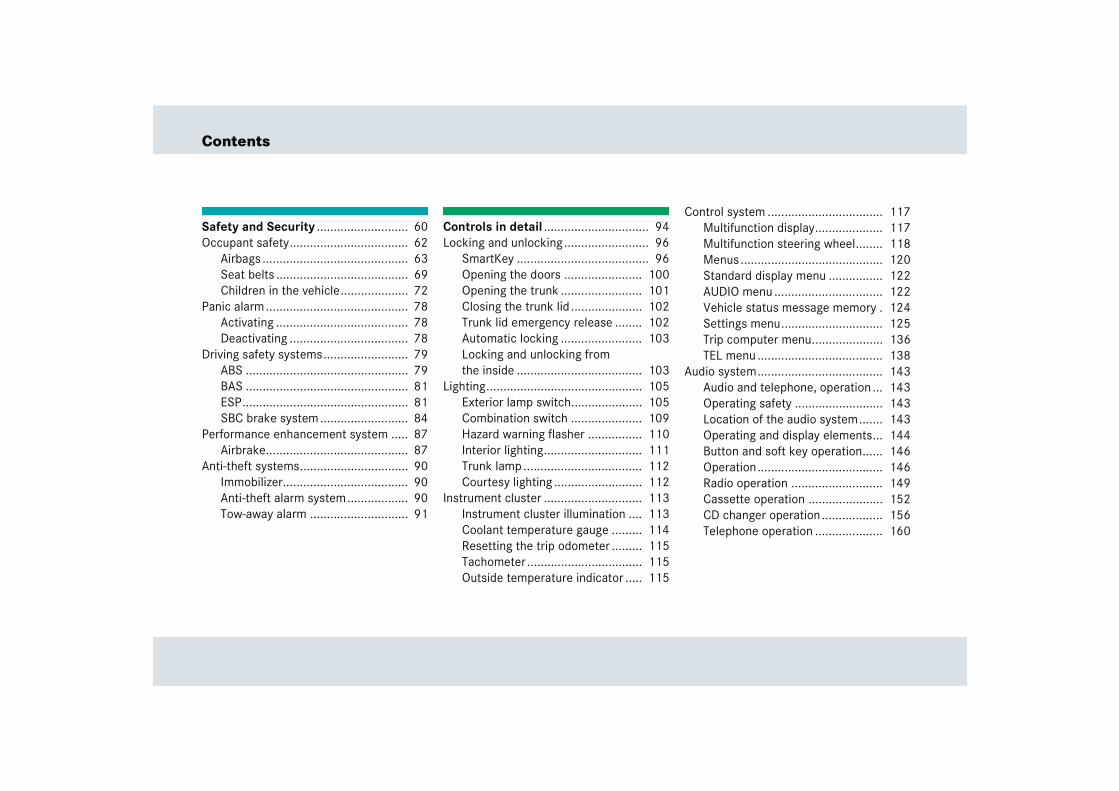
Safety and Security ........................... 60Occupant safety................................... 62
Airbags ........................................... 63Seat belts ....................................... 69Children in the vehicle.................... 72
Panic alarm.......................................... 78Activating ....................................... 78Deactivating ................................... 78
Driving safety systems......................... 79ABS ................................................ 79BAS ................................................ 81ESP................................................. 81SBC brake system .......................... 84
Performance enhancement system ..... 87Airbrake.......................................... 87
Anti-theft systems................................ 90Immobilizer..................................... 90Anti-theft alarm system.................. 90Tow-away alarm ............................. 91
Controls in detail ............................... 94Locking and unlocking ......................... 96
SmartKey ....................................... 96Opening the doors ....................... 100Opening the trunk ........................ 101Closing the trunk lid ..................... 102Trunk lid emergency release ........ 102Automatic locking ........................ 103Locking and unlocking from the inside ..................................... 103
Lighting.............................................. 105Exterior lamp switch..................... 105Combination switch ..................... 109Hazard warning flasher ................ 110Interior lighting............................. 111Trunk lamp ................................... 112Courtesy lighting .......................... 112
Instrument cluster ............................. 113Instrument cluster illumination .... 113Coolant temperature gauge ......... 114Resetting the trip odometer ......... 115Tachometer.................................. 115Outside temperature indicator ..... 115
Control system .................................. 117Multifunction display.................... 117Multifunction steering wheel........ 118Menus.......................................... 120Standard display menu ................ 122AUDIO menu ................................ 122Vehicle status message memory . 124Settings menu.............................. 125Trip computer menu..................... 136TEL menu ..................................... 138
Audio system..................................... 143Audio and telephone, operation ... 143Operating safety .......................... 143Location of the audio system....... 143Operating and display elements... 144Button and soft key operation...... 146Operation..................................... 146Radio operation ........................... 149Cassette operation ...................... 152CD changer operation.................. 156Telephone operation .................... 160
Contents
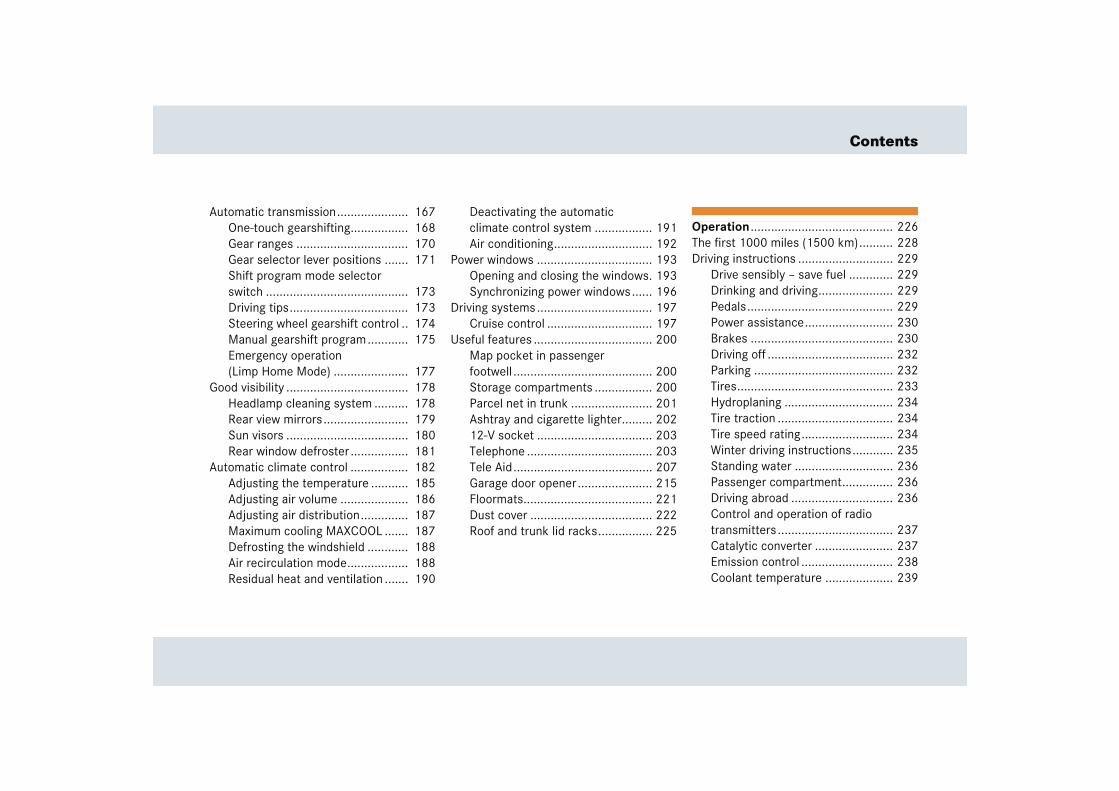
Automatic transmission..................... 167One-touch gearshifting................. 168Gear ranges ................................. 170Gear selector lever positions ....... 171Shift program mode selector switch .......................................... 173Driving tips................................... 173Steering wheel gearshift control .. 174Manual gearshift program............ 175Emergency operation (Limp Home Mode) ...................... 177
Good visibility .................................... 178Headlamp cleaning system .......... 178Rear view mirrors......................... 179Sun visors .................................... 180Rear window defroster ................. 181
Automatic climate control ................. 182Adjusting the temperature ........... 185Adjusting air volume .................... 186Adjusting air distribution.............. 187Maximum cooling MAXCOOL ....... 187Defrosting the windshield ............ 188Air recirculation mode.................. 188Residual heat and ventilation ....... 190
Deactivating the automatic climate control system ................. 191Air conditioning............................. 192
Power windows .................................. 193Opening and closing the windows. 193Synchronizing power windows...... 196
Driving systems .................................. 197Cruise control ............................... 197
Useful features ................................... 200Map pocket in passenger footwell ......................................... 200Storage compartments ................. 200Parcel net in trunk ........................ 201Ashtray and cigarette lighter......... 20212-V socket .................................. 203Telephone ..................................... 203Tele Aid......................................... 207Garage door opener...................... 215Floormats...................................... 221Dust cover .................................... 222Roof and trunk lid racks................ 225
Operation .......................................... 226The first 1000 miles (1500 km).......... 228Driving instructions ............................ 229
Drive sensibly – save fuel ............. 229Drinking and driving...................... 229Pedals........................................... 229Power assistance.......................... 230Brakes .......................................... 230Driving off ..................................... 232Parking ......................................... 232Tires.............................................. 233Hydroplaning ................................ 234Tire traction .................................. 234Tire speed rating........................... 234Winter driving instructions............ 235Standing water ............................. 236Passenger compartment............... 236Driving abroad .............................. 236Control and operation of radio transmitters .................................. 237Catalytic converter ....................... 237Emission control ........................... 238Coolant temperature .................... 239

Contents
At the gas station............................... 240Refueling ...................................... 240Check regularly and before a long trip ..................................... 241
Engine compartment.......................... 243Hood ............................................ 243Engine oil...................................... 246Transmission fluid level ................ 248Coolant......................................... 249
Trunk ................................................. 250Batteries....................................... 250Windshield washer system and headlamp cleaning system........... 251
Tires and wheels ................................ 253Important guidelines .................... 253Tire care and maintenance........... 254Direction of rotation ..................... 256Loading the vehicle ...................... 256Recommended tire inflation pressure ....................................... 262Checking tire inflation pressure ... 264Tire labeling.................................. 268Load identification........................ 272DOT, Tire Identification Number (TIN) ............................................. 273
Maximum tire load ....................... 274Maximum tire inflation pressure .. 275Uniform Tire Quality Grading Standards (U.S. vehicles) ............. 276Tire ply material ........................... 278Tire and loading terminology........ 278Rotating tires ............................... 281Anti-theft wheel nuts.................... 282
Winter driving .................................... 284Winter tires* ................................ 284Snow chains................................. 285
Maintenance...................................... 286Clearing the maintenance service indicator........................... 286Maintenance service term exceeded ..................................... 287Calling up the service due date .... 287Resetting the maintenance service indicator........................... 288
Vehicle care....................................... 289Cleaning and care of the vehicle .. 289Vehicle washing ........................... 290
Practical hints ................................. 294What to do if ... .................................. 296
Lamps in instrument cluster ........ 296Lamp in center console................ 303Vehicle status messages in the multifunction display.................... 304Symbol messages ........................ 309
Where will I find ...? ........................... 340First aid kit................................... 340TIREFIT kit, electric air pump, towing eye bolt and vehicle literature portfolio........................ 340
Locking/unlocking in an emergency . 342Unlocking the vehicle................... 342
Replacing SmartKey batteries ........... 344SmartKey ..................................... 345
Replacing bulbs ................................. 346Front lamps.................................. 347Rear lamps................................... 347
Replacing the wiper blades................ 348Removing wiper blades ................ 348Installing wiper blades ................. 348

Contents
Flat tire .............................................. 349Preparing the vehicle ................... 349Sealing tires with TIREFIT kit........ 349
Batteries ............................................ 354Charging the batteries ................. 355
Towing the vehicle ............................. 357Installing/reinstalling towing eye bolt ........................................ 359Points to bear in mind.................. 360Transporting the vehicle............... 360
Fuses ................................................. 361
Technical data .................................. 362Spare parts service............................. 364Warranty coverage ............................. 365
Loss of Service and Warranty Information Booklet ...................... 365
Identification labels ............................ 366Engine number.............................. 366
Layout of poly-V-belt drive.................. 367Engine ................................................ 368Rims and tires .................................... 369
Mixed size tires............................. 370Winter tires* ................................. 371
Electrical system ................................ 372Main dimensions ................................ 373Weights .............................................. 374
Fuels, coolants, lubricants, etc........... 375Capacities..................................... 375Engine oils .................................... 377Engine oil additives....................... 377Air conditioner refrigerant ............ 377Brake fluid .................................... 378Premium unleaded gasoline.......... 378Fuel requirements......................... 378Gasoline additives......................... 379Coolants ....................................... 380Windshield and headlamp washer system.............................. 382
Technical terms ............................... 384
Index ................................................. 390

Introduct ion
13
Introduction
Product information
� Product informationPlease observe the following in your own best interest:
We recommend using genuine Mercedes-Benz parts as well as conversion parts and accessories explicitly approved by us for your vehicle model.
We have tested these parts to determine their reliability, safety and special suitabili-ty for Mercedes-Benz vehicles.
We are unable to make an assessment for other products and therefore cannot be held responsible for them, even if in indi-vidual cases an official approval or authori-zation by governmental or other agencies should exist. Use of such parts and acces-sories could adversely affect the safety, performance or reliability of your vehicle. Please do not use them.
Genuine Mercedes-Benz parts as well as conversion parts and accessories ap-proved by us are available at an authorized Mercedes-Benz Center where you will re-ceive comprehensive information, also on permissible technical modifications, and where proper installation will be per-formed.
14
Introduction
Operator’s Manual
This Operator’s Manual contains a great deal of useful information. We urge you to read it carefully and familiarize yourself with the vehicle before driving.
For your own safety and longer service life of the vehicle, we urge you to follow the in-structions and warnings contained in this manual. Ignoring them could result in dam-age to the vehicle or personal injury to you or others. Vehicle damage caused by fail-ure to follow instructions is not covered by the Mercedes-Benz Limited Warranty.
Your vehicle may have some or all of the equipment described in this manual. Therefore, you may find explanations for optional equipment not installed in your vehicle. If you have any questions about the operation of any equipment, your au-thorized Mercedes-Benz Center will be glad to demonstrate the proper proce-dures.
We continuously strive to improve our product, and ask for your understanding that we reserve the right to make changes in design and equipment. Therefore, infor-mation, illustrations, and descriptions in this Operator’s Manual might differ from your vehicle.
Optional equipment is also described in this manual, including operating instruc-tions wherever necessary. Since they are special-order items, the descriptions and illustrations herein may vary slightly from the actual equipment of your vehicle.
If there are any equipment details that are not shown or described in this Operator’s Manual, an authorized Mercedes-Benz Center will be glad to inform you of correct care and operating procedures.
The Operator’s Manual and Maintenance Booklet are important documents and should be kept with the vehicle.
Service and warranty information
The Service and Warranty Information Booklet contains detailed information about the warranties covering your Mercedes-Benz, including:
� New Car Limited Warranty,
� Emission System Warranty,
� Emission Performance Warranty,
� California, Maine, Massachusetts and Vermont1 Emission Control System Warranty (California, Maine, Massa-chusetts and Vermont1 only),
� State Warranty Enforcement Laws (Lemon Laws).
1 At time of printing, the decision regarding compli-ance with Vermont certification regulations was still pending. The vehicle may not be permitted to be registered in Vermont. Check with an autho-rized Mercedes-Benz Center for details.
15
Introduction
Operator’s Manual
Important notice for California retail buyers and lessees of Mercedes-Benz automobiles
Under California law you may be entitled to a replacement of your vehicle or a refund of the purchase price or lease price, if Mercedes-Benz USA, LLC and/or its au-thorized repair or service facilities fail to fix one or more substantial defects or mal-functions in the vehicle that are covered by its express warranty after a reasonable number of repair attempts. During the pe-riod of 18 months from original delivery of the vehicle or the accumulation of 18000 miles (approx. 29000 km) on the odometer of the vehicle, whichever occurs first, a reasonable number of repair at-tempts is presumed for a retail buyer or lessee if one or more of the following oc-curs:
(1) the same substantial defect or mal-function results in a condition that is likely to cause death or serious bodily injury if the vehicle is driven, that de-fect or malfunction has been subject to repair two or more times, and you have directly notified Mercedes-Benz USA, LLC in writing of the need for its repair,
(2) the same substantial defect or mal-function of a less serious nature than category (1) has been subject to repair four or more times and you have direct-ly notified us in writing of the need for its repair, or
(3) the vehicle is out of service by reason of repair of the same or different sub-stantial defects or malfunctions for a cumulative total of more than 30 calendar days.
Written notification should be sent to us, not a dealer, at Mercedes-Benz USA, LLC, Customer Assistance Center, Attn: SLR Liaison, Three Paragon Drive, Montvale, NJ 07645-0350.
16
Introduction
Operator’s Manual
Maintenance
The Maintenance Booklet describes all the necessary maintenance work which should be performed at regular intervals.
Always have the Maintenance Booklet with you when you take the vehicle to your au-thorized Mercedes-Benz Center for ser-vice. The service advisor will record each service in the booklet for you.
Roadside Assistance
The Mercedes-Benz Roadside Assistance Program provides factory trained technical help in the event of a breakdown. Calls to the toll-free Roadside Assistance number:
1-800-FOR-MERCedes (in the USA)1-888-881-6611 (in Canada)
will be answered by Mercedes-Benz Customer Assistance Representatives 24 hours a day, 365 days a year.
For additional information refer to the Mercedes-Benz Roadside Assistance Program brochure in your vehicle literature portfolio.
Change of address or ownership
If you change your address, be sure to send in the “Change of Address Notice” found in the Service and Warranty Informa-tion Booklet, or simply call the Mercedes-Benz Customer Assistance Center (in the USA) at 1-800-FOR-MERCedes, or Customer Service (in Canada) at 1-888-881-6611. It is in your own interest that we can contact you should the need arise.
If you sell your Mercedes, please leave all literature with the vehicle to make it avail-able to the next operator.
If you bought this vehicle used, be sure to send in the “Notice of Purchase of Used Car” found in the Service and Warranty In-formation Booklet, or call the Mercedes-Benz Customer Assistance Cen-ter (in the USA) at 1-800-FOR-MERCedes, or Customer Service (in Canada) at 1-888-881-6611.

17
Introduction
Operator’s Manual
Operating your vehicle outside the USA or Canada
If you plan to operate your vehicle in for-eign countries, please be aware that:
� service facilities or replacement parts may not be readily available,
� unleaded gasoline for vehicles with cat-alytic converters may not be available; the use of leaded fuels will damage the catalysts,
� gasoline may have a considerably low-er octane rating, and improper fuel can cause engine damage.
Mercedes-Benz SLR McLaren compliance
The Mercedes-Benz SLR McLaren vehicle does not comply with the state certifica-tion regulations of select states. It is not permitted to register the vehicle in such states. Check with an authorized Mercedes-Benz Center for details.
18
Introduction
Where to find it
This Operator’s Manual is designed to pro-vide comprehensive support information for you, the vehicle operator. For you to find information quickly each section has its own reference color:
At a glance
Here you will find an overview of all the controls that can be operated from the driver’s seat.
Getting started
Here you will find all the information you need for your first drive. You should read this section first if this is your first Mercedes-Benz vehicle or if you are rent-ing or borrowing this vehicle.
Safety and Security
Here you will find descriptions of the safety and security features in your vehicle.
Controls in detail
Here you will find detailed information about the equipment installed on your ve-hicle. This section expands on the “Getting started” section and also describes techni-cal innovations. If you are already familiar with the basic functions of your vehicle, this section will be of particular interest to you.
Operation
Here you will find all the information you need for the proper operation of your vehi-cle.
Practical hints
This section provides fast assistance for dealing with problems you may encounter.
Technical data
All important technical data for your vehi-cle can be found in this section.
Indexes
The glossary provides explanations of the most important technical terms.
The table of contents and the index are de-signed to help you find information quickly and easily.
The following publications are part of your vehicle documentation:
� this Operator’s Manual
� the Maintenance Booklet
Separate operating instructions will be provided as required depending on the equipment options installed in your vehi-cle.
19
Introduction
Symbols
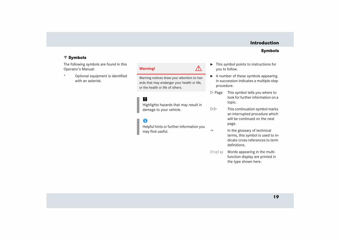
� SymbolsThe following symbols are found in this Operator’s Manual:
* Optional equipment is identified with an asterisk.
� This symbol points to instructions for you to follow.
� A number of these symbols appearing in succession indicates a multiple-step procedure.
� Page This symbol tells you where to look for further information on a topic.
�� This continuation symbol marks an interrupted procedure which will be continued on the next page.
-> In the glossary of technical terms, this symbol is used to in-dicate cross-references to term definitions.
Display Words appearing in the multi-function display are printed in the type shown here.
Warning! G
Warning notices draw your attention to haz-ards that may endanger your health or life, or the health or life of others.
!Highlights hazards that may result in damage to your vehicle.
iHelpful hints or further information you may find useful.

20
Introduction
Operating safety
Proper use of the vehicle
Proper use of the vehicle requires that you are familiar with the following information and rules:
� the safety precautions in this manual
� the “Technical data” section in this manual
� traffic rules and regulations
� motor vehicle laws and safety stan-dards
Warning! G
Work improperly carried out on electronic components and associated software could cause them to cease functioning. Because the vehicle’s electronic components are in-terconnected, any modifications made may produce an undesired effect on other sys-tems. Electronic malfunctions could seri-ously impair the operating safety of your vehicle.
See an authorized Mercedes-Benz Center for repairs or modifications to electronic components.
Other improper work or modifications on the vehicle could also have a negative impact on the operating safety of the vehicle.
Some safety systems only function while the engine is running. You should therefore nev-er turn off the engine while driving.
Warning! G
Heavy blows against the vehicle underbody or tires/wheels, for example when running over an obstacle, road debris or a pothole, may cause serious damage and impair the operating safety of your vehicle. If you feel a sudden significant vibration or ride distur-bance, or you suspect that damage to your vehicle has occurred, you should turn on your hazard warning flashers, carefully slow down, and drive with caution to an area which is a safe distance from the road.
Inspect the vehicle underbody and tires/wheels for possible damage. If the ve-hicle appears unsafe, have it towed to the nearest authorized Mercedes-Benz Center or other qualified maintenance or repair fa-cility for further inspection or repairs.
Warning G
Various warning labels are attached to your vehicle. These warning labels are intended to make you and others aware of various risks. You should not remove any of these warning labels unless explicitly instructed to do so by information on the label itself. Re-moval of any of these labels may cause you and others to be unaware of certain risks which may result in an accident and/or per-sonal injury.
21
Introduction
Problems with your vehicle
� Problems with your vehicleIf you should experience a problem with your vehicle, particularly one that you believe may affect its safe operation, we urge you to immediately contact an authorized Mercedes-Benz Center to have the problem diagnosed and corrected if required. If the matter is not handled to your satisfaction, please discuss the problem with the Mercedes-Benz Center management, or if necessary contact us at one of the following addresses:
In the USA:
Customer Assistance CenterAttn: SLR LiaisonMercedes-Benz USA, LLCThree Paragon Drive Montvale, NJ 07645-0350
In Canada:
Customer Relations DepartmentMercedes-Benz Canada, Inc.98 Vanderhoof AvenueToronto, Ontario M4G 4C9

22
Introduction
Reporting safety defects
For the USA only:The following text is published as required of manufacturers under Title 49, Code of U.S. Federal Regulations, Part 575 pursuant to the “National Traffic and Motor Vehicle Safety Act of 1966”.
Reporting safety defects
If you believe that your vehicle has a defect which could cause a crash or could cause injury or death, you should immediately inform the National Highway Traffic Safety Administration (NHTSA) in addition to notifying Mercedes-Benz USA, LLC.
If NHTSA receives similar complaints, it may open an investigation, and if it finds that a safety defect exists in a group of vehicles, it may order a recall and remedy campaign. However, NHTSA cannot become involved in individual problems between you, your dealer, or Mercedes-Benz USA, LLC.
To contact NHTSA, you may either call the Auto Safety Hotline toll-free at 1-888-327-4236 (or 366-0123 in Washington, D.C. area) or write to: NHTSA, U.S. Department of Transportation, Washington, D.C. 20590. You can also obtain other information about motor ve-hicle safety from the Hotline.
23
Introduction
Vehicle data recording
� Vehicle data recordingInformation regarding electronic recording devices
(Including notice pursuant to California Code § 9951)
Please note that your vehicle is equipped with devices that can record vehicle systems data and, if equipped with the Tele Aid system, may transmit some data in certain accidents.
This information helps, for example, to diagnose vehicle systems after a collision and to continuously improve vehicle safety. DaimlerChrysler may access the information and share it with others
� for safety research or vehicle diagnosis purposes
� with the consent of the vehicle owner or lessee
� in response to an official request by law enforcement or other government agency
� for use in dispute resolution involving DaimlerChrysler, its affiliates or sales/service organization and/or
� as otherwise required or permitted by law.
Please check the Tele Aid subscription service agreement for details regarding the information that may be recorded or transmitted via that system.
At a glance
Cockpit
Instrument cluster
Multifunction steering wheel
Center console
Overhead control panel
Control panel on the door sill
26
At a glance
Cockpit
27
At a glance
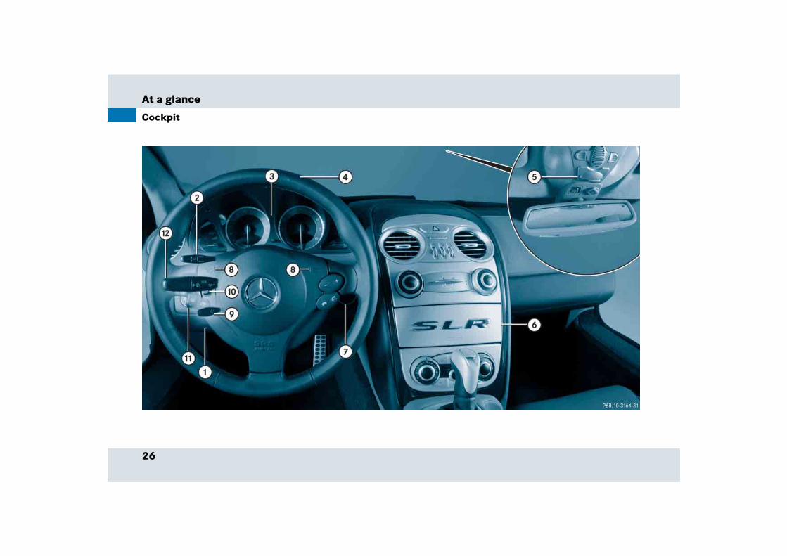
Cockpit
Item Page
1 Hood lock release 243
2 Cruise control lever 197
3 Instrument cluster 28,113
4 Multifunction steering wheel 30,118
5 Overhead control panel 33
6 Center console 31, 32
7 Starter switch 40
8 Horn
Item Page
9 Steering wheel adjustment stalk
42
a Headlamp washer button 178
b Exterior lamp switch 51,105
c Combination switch
� Turn signals
� Windshield wipers
� High beam
52
53
109
28
At a glance
Instrument cluster
29
At a glance
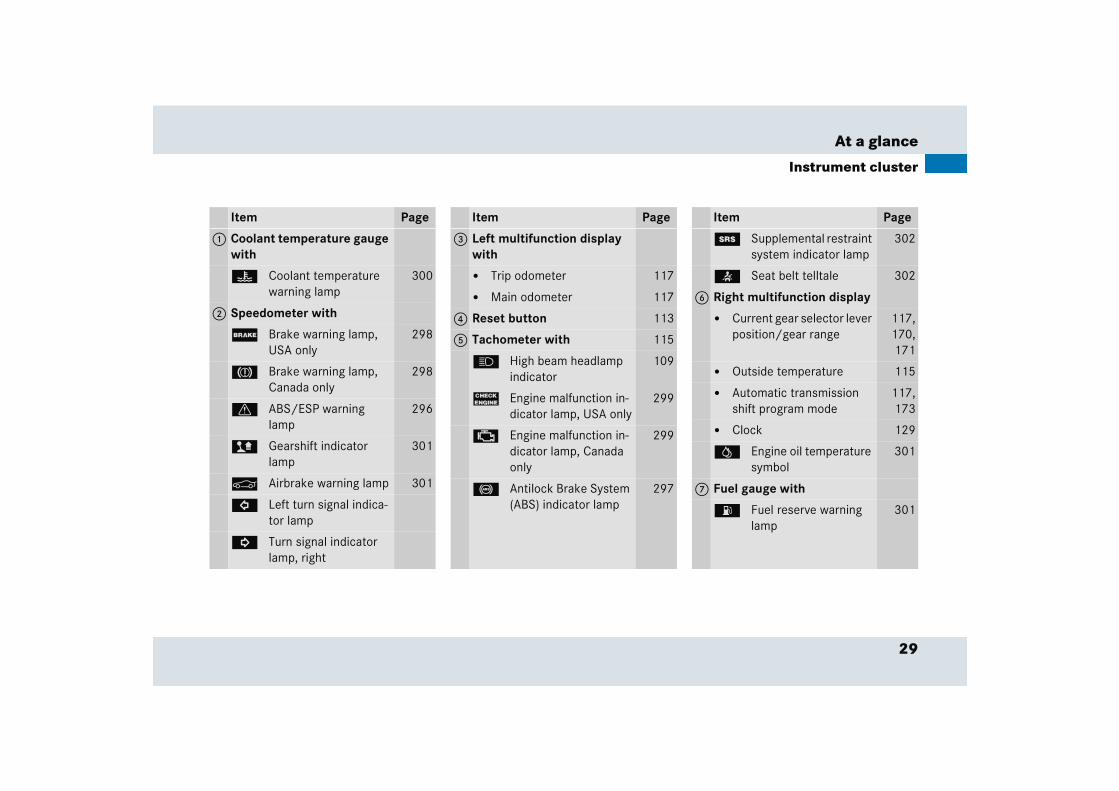
Instrument cluster
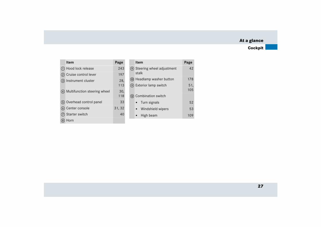
Item Page
1 Coolant temperature gauge with
D Coolant temperature warning lamp
300
2 Speedometer with
; Brake warning lamp, USA only
298
3 Brake warning lamp, Canada only
298
v ABS/ESP warning lamp
296
> Gearshift indicator lamp
301
< Airbrake warning lamp 301
L Left turn signal indica-tor lamp
K Turn signal indicator lamp, right
Item Page
3 Left multifunction display with
� Trip odometer 117
� Main odometer 117
4 Reset button 113
5 Tachometer with 115
A High beam headlamp indicator
109
? Engine malfunction in-dicator lamp, USA only
299
± Engine malfunction in-dicator lamp, Canada only
299
- Antilock Brake System (ABS) indicator lamp
297
Item Page
1 Supplemental restraint system indicator lamp
302
< Seat belt telltale 302
6 Right multifunction display
� Current gear selector lever position/gear range
117,170,171
� Outside temperature 115
� Automatic transmission shift program mode
117,173
� Clock 129
= Engine oil temperature symbol
301
7 Fuel gauge with
A Fuel reserve warning lamp
301
30
At a glance
Multifunction steering wheel
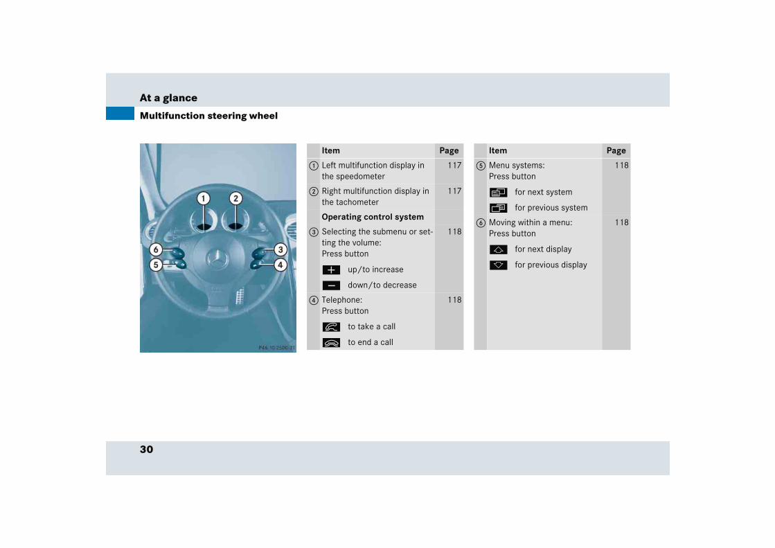
Item Page
1 Left multifunction display in the speedometer
117
2 Right multifunction display in the tachometer
117
Operating control system
3 Selecting the submenu or set-ting the volume:Press button
æ up/to increase
ç down/to decrease
118
4 Telephone:Press button
í to take a call
ì to end a call
118
Item Page
5 Menu systems:Press button
è for next system
ÿ for previous system
118
6 Moving within a menu:Press button
j for next display
k for previous display
118
31
At a glance
Center console
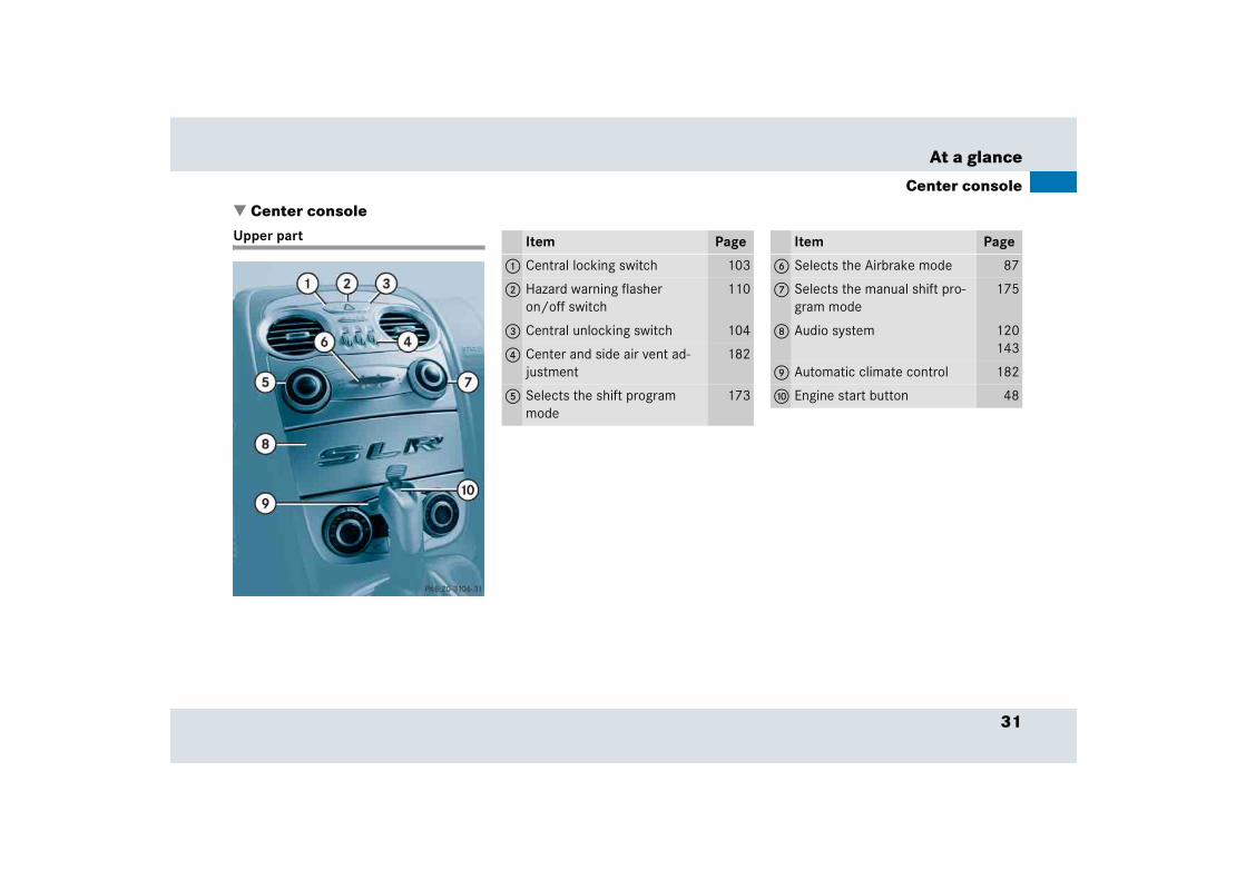
� Center consoleUpper part Item Page
1 Central locking switch 103
2 Hazard warning flasher on/off switch
110
3 Central unlocking switch 104
4 Center and side air vent ad-justment
182
5 Selects the shift program mode
173
Item Page
6 Selects the Airbrake mode 87
7 Selects the manual shift pro-gram mode
175
8 Audio system 120143
9 Automatic climate control 182
a Engine start button 48
32
At a glance
Center console
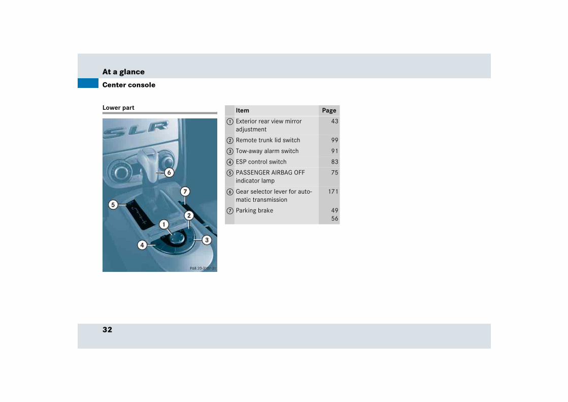
Lower part Item Page
1 Exterior rear view mirror adjustment
43
2 Remote trunk lid switch 99
3 Tow-away alarm switch 91
4 ESP control switch 83
5 PASSENGER AIRBAG OFF indicator lamp
75
6 Gear selector lever for auto-matic transmission
171
7 Parking brake 4956

33
At a glance
Overhead control panel
� Overhead control panel
Item Page
1 Left reading lamp on/off 111
2 Temperature sensor for auto-matic climate control
182
3 Right reading lamp on/off 111
4 Interior lighting control 111
5 Hands-free microphone for Tele Aid (emergency call system) and telephone (see separate operating instructions)
203
6 Interior rear view mirror 43,179
7 Garage door opener 215
8 Tele Aid (emergency call system) button
207
34
At a glance
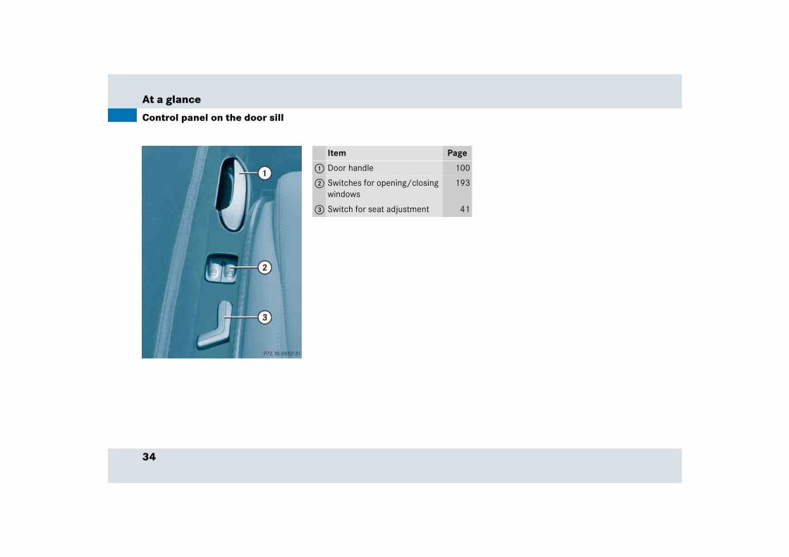
Control panel on the door sill
Item Page
1 Door handle 100
2 Switches for opening/closing windows
193
3 Switch for seat adjustment 41

35

Getting started
Unlocking
Adjusting
Driving
Parking and locking
38
Getting started
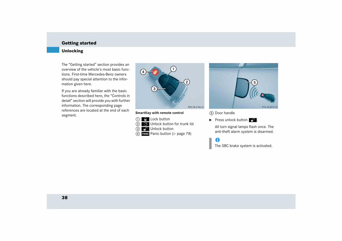
The “Getting started” section provides an overview of the vehicle’s most basic func-tions. First-time Mercedes-Benz owners should pay special attention to the infor-mation given here.
If you are already familiar with the basic functions described here, the “Controls in detail” section will provide you with further information. The corresponding page references are located at the end of each segment.
Unlocking
SmartKey with remote control
1 ‹ Lock button2 Š Unlock button for trunk lid3 Œ Unlock button4  Panic button (� page 78)
5 Door handle
� Press unlock button Œ.
All turn signal lamps flash once. The anti-theft alarm system is disarmed.
iThe SBC brake system is activated.
39
Getting started
Unlocking
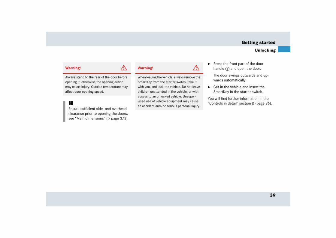
� Press the front part of the door handle 5 and open the door.
The door swings outwards and up-wards automatically.
� Get in the vehicle and insert the SmartKey in the starter switch.
You will find further information in the “Controls in detail” section (� page 96).
Warning! G
Always stand to the rear of the door before opening it, otherwise the opening action may cause injury. Outside temperature may affect door opening speed.
!Ensure sufficient side- and overhead clearance prior to opening the doors, see “Main dimensions” (� page 373).
Warning! G
When leaving the vehicle, always remove the SmartKey from the starter switch, take it with you, and lock the vehicle. Do not leave children unattended in the vehicle, or with access to an unlocked vehicle. Unsuper-vised use of vehicle equipment may cause an accident and/or serious personal injury.
40
Getting started
Unlocking
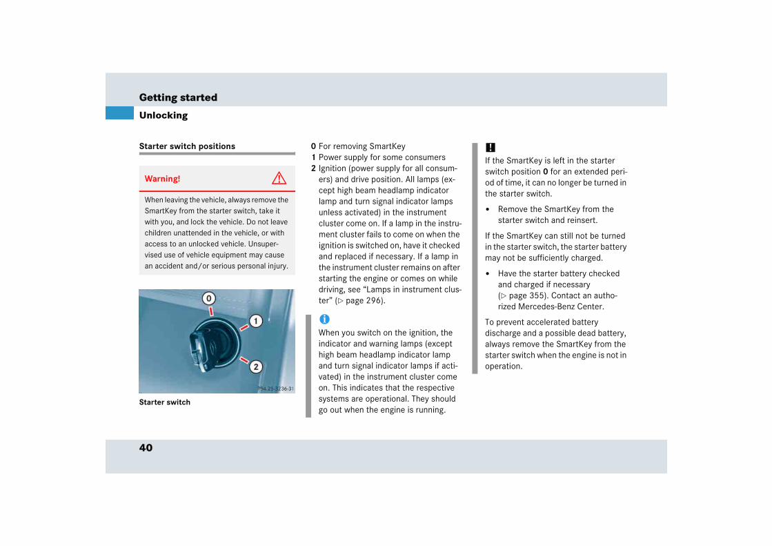
Starter switch positions
Starter switch
0 For removing SmartKey1 Power supply for some consumers 2 Ignition (power supply for all consum-
ers) and drive position. All lamps (ex-cept high beam headlamp indicator lamp and turn signal indicator lamps unless activated) in the instrument cluster come on. If a lamp in the instru-ment cluster fails to come on when the ignition is switched on, have it checked and replaced if necessary. If a lamp in the instrument cluster remains on after starting the engine or comes on while driving, see “Lamps in instrument clus-ter” (� page 296).
Warning! G
When leaving the vehicle, always remove the SmartKey from the starter switch, take it with you, and lock the vehicle. Do not leave children unattended in the vehicle, or with access to an unlocked vehicle. Unsuper-vised use of vehicle equipment may cause an accident and/or serious personal injury.
iWhen you switch on the ignition, the indicator and warning lamps (except high beam headlamp indicator lamp and turn signal indicator lamps if acti-vated) in the instrument cluster come on. This indicates that the respective systems are operational. They should go out when the engine is running.
!If the SmartKey is left in the starter switch position 0 for an extended peri-od of time, it can no longer be turned in the starter switch.
� Remove the SmartKey from the starter switch and reinsert.
If the SmartKey can still not be turned in the starter switch, the starter battery may not be sufficiently charged.
� Have the starter battery checked and charged if necessary (� page 355). Contact an autho-rized Mercedes-Benz Center.
To prevent accelerated battery discharge and a possible dead battery, always remove the SmartKey from the starter switch when the engine is not in operation.

41
Getting started
Adjusting
� Adjusting
Seats
The seat adjustment switch is located on the door sill.
1 Seat fore and aft adjustment2 Seat height3 Seat angle
Warning! G
All seat, steering wheel, and rear view mirror adjustments, as well as fastening of seat belts, must be done before the vehicle is put into motion.
Warning! G
Do not adjust the driver’s seat while driving. Adjusting the seat while driving could cause the driver to lose control of the vehicle.
Never place hands under the seat or near any moving parts while a seat is being ad-justed.
Never ride in a moving vehicle with the seat back in an excessively reclined position as this can be dangerous. You could slide un-der the seat belt in a collision. If you slide under it, the belt would apply force at the ab-domen or neck.
That could cause serious or fatal injuries. The seat back and seat belts provide the best restraint when the wearer is in a nearly upright position and belts are properly posi-tioned on the body. Your seat must be ad-justed so that you can correctly fasten your seat belt (� page 45).
Warning! G
When leaving the vehicle, always remove the SmartKey from the starter switch, take it with you, and lock the vehicle.
Even with the SmartKey removed from the starter switch or the vehicle, the seats can be operated. Therefore, do not leave chil-dren unattended in the vehicle, or with ac-cess to an unlocked vehicle. Unsupervised use of vehicle equipment may cause an ac-cident and/or serious personal injury.
42
Getting started
Adjusting
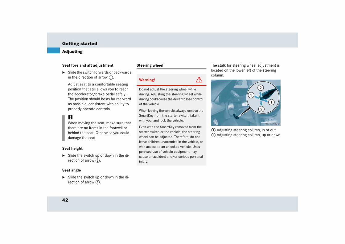
Seat fore and aft adjustment
� Slide the switch forwards or backwards in the direction of arrow 1.
Adjust seat to a comfortable seating position that still allows you to reach the accelerator/brake pedal safely. The position should be as far rearward as possible, consistent with ability to properly operate controls.
Seat height
� Slide the switch up or down in the di-rection of arrow 2.
Seat angle
� Slide the switch up or down in the di-rection of arrow 3.
Steering wheel The stalk for steering wheel adjustment is located on the lower left of the steering column.
1 Adjusting steering column, in or out2 Adjusting steering column, up or down
!When moving the seat, make sure that there are no items in the footwell or behind the seat. Otherwise you could damage the seat.
Warning! G
Do not adjust the steering wheel while driving. Adjusting the steering wheel while driving could cause the driver to lose control of the vehicle.
When leaving the vehicle, always remove the SmartKey from the starter switch, take it with you, and lock the vehicle.
Even with the SmartKey removed from the starter switch or the vehicle, the steering wheel can be adjusted. Therefore, do not leave children unattended in the vehicle, or with access to an unlocked vehicle. Unsu-pervised use of vehicle equipment may cause an accident and/or serious personal injury.
43
Getting started
Adjusting
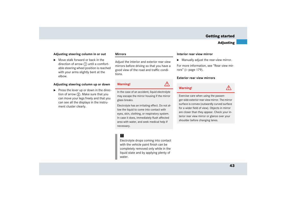
Adjusting steering column in or out
� Move stalk forward or back in the direction of arrow 1 until a comfort-able steering wheel position is reached with your arms slightly bent at the elbow.
Adjusting steering column up or down
� Press the lever up or down in the direc-tion of arrow 2. Make sure that you can move your legs freely and that you can see all the displays in the instru-ment cluster clearly.
Mirrors
Adjust the interior and exterior rear view mirrors before driving so that you have a good view of the road and traffic condi-tions.
Interior rear view mirror
� Manually adjust the rear-view mirror.
For more information, see “Rear view mir-rors” (� page 179).
Exterior rear view mirrors
Warning! G
In the case of an accident, liquid electrolyte may escape the mirror housing if the mirror glass breaks.
Electrolyte has an irritating effect. Do not al-low the liquid to come into contact with eyes, skin, clothing, or respiratory system. In case it does, immediately flush affected area with water, and seek medical help if necessary.
!Electrolyte drops coming into contact with the vehicle paint finish can be completely removed only while in the liquid state and by applying plenty of water.
Warning! G
Exercise care when using the passen-ger-side exterior rear view mirror. The mirror surface is convex (outwardly curved surface for a wider field of view). Objects in mirror are closer than they appear. Check your in-terior rear view mirror or glance over your shoulder before changing lanes.
44
Getting started
Adjusting
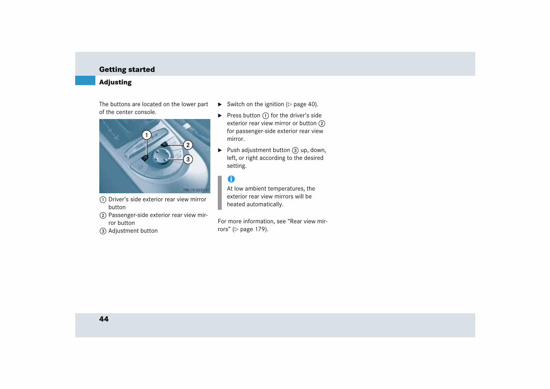
The buttons are located on the lower part of the center console.
1 Driver’s side exterior rear view mirror button
2 Passenger-side exterior rear view mir-ror button
3 Adjustment button
� Switch on the ignition (� page 40).
� Press button 1 for the driver’s side exterior rear view mirror or button 2 for passenger-side exterior rear view mirror.
� Push adjustment button 3 up, down, left, or right according to the desired setting.
For more information, see “Rear view mir-rors” (� page 179).
iAt low ambient temperatures, the exterior rear view mirrors will be heated automatically.
45
Getting started
Driving
� Driving
Fastening the seat belts
Warning! G
Do not lay any objects in the driver’s foot-well. Be careful that floor mats or carpets in the driver’s footwell have sufficient clear-ance for the pedals.
During sudden driving or braking maneuvers the objects could get caught between the pedals. You could then no longer brake or accelerate.
Warning! G
Always fasten your seat belt before driving off. Always make sure your passenger is properly restrained, even pregnant women.
Failure to wear and properly fasten and po-sition your seat belt greatly increases your risk of injuries and their likely severity in an accident. You and your passenger should al-ways wear seat belts.
If you are ever in an accident, your injuries can be considerably more severe without your seat belt properly buckled. Without your seat belt buckled, you are much more likely to hit the interior of the vehicle or be ejected from it. You can be seriously injured or killed.
In the same crash, the possibility of injury or death is lessened if you are wearing your seat belt. The airbags can only provide the protection they were designed to afford if the occupants are using their seat belts (� page 69).
Warning! G
Children 12 years old and under must never ride in this vehicle, except in a Mercedes-Benz authorized BabySmartTM1 compatible child seat, which operates with the BabySmartTM system installed in the ve-hicle to deactivate the passenger front air-bag when it is properly installed. Otherwise they will be struck by the airbag when it in-flates in a crash. If this happens, serious or fatal injury will result.
Infants and small children must be seated in an appropriate BabySmartTM compatible in-fant or child restraint system, which is prop-erly secured with the vehicle’s seat belt and top tether strap, fully in accordance with the child seat manufacturer’s instructions.
1 BabySmartTM is a trademark of Siemens Automotive Corp.
��
46
Getting started
Driving
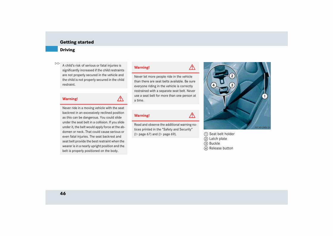
1 Seat belt holder 2 Latch plate 3 Buckle4 Release button
A child’s risk of serious or fatal injuries is significantly increased if the child restraints are not properly secured in the vehicle and the child is not properly secured in the child restraint.
Warning! G
Never ride in a moving vehicle with the seat backrest in an excessively reclined position as this can be dangerous. You could slide under the seat belt in a collision. If you slide under it, the belt would apply force at the ab-domen or neck. That could cause serious or even fatal injuries. The seat backrest and seat belt provide the best restraint when the wearer is in a nearly upright position and the belt is properly positioned on the body.
Warning! G
Never let more people ride in the vehicle than there are seat belts available. Be sure everyone riding in the vehicle is correctly restrained with a separate seat belt. Never use a seat belt for more than one person at a time.
Warning! G
Read and observe the additional warning no-tices printed in the “Safety and Security” (� page 67) and (� page 69).
��
47
Getting started
Driving
� Pull the belt smoothly from seat belt holder 1.
� Place the shoulder portion of the belt across the top of your shoulder and the lap portion across your hips.
� Push latch plate 2 into buckle 3 until it clicks.
� If necessary, tighten the lap portion to a snug fit by pulling shoulder portion up.
Proper use of seat belts
� Do not twist the belt when fastening.
� Adjust seat belt so that the shoulder portion is located as close as possible to the middle of the shoulder (it should not touch the neck). Never pass the shoulder portion of the belt under your arm.
� Position the lap belt as low as possible on your hips (over hip joint) and not across the abdomen.
� Place the seat backrest in a nearly up-right position.
� Never use a seat belt for more than one person at a time.
� Do not fasten a seat belt around a per-son and another object at the same time. When using a seat belt to secure infant or toddler restraints or children in booster seats, always follow the child seat manufacturer’s instructions.
� Check your seat belt during travel to make sure that it is properly positioned.
� Make sure that the seat belt is always fitted snugly. Take special care of this when wearing loose clothing.
Warning! G
Do not pass belts over sharp edges. They could tear.
Do not allow the belt to get caught in the door or in the seat adjustment mechanism. This could damage the belt.
Never attempt to make modifications to seat belts. This could impair the effective-ness of the belts.
Do not bleach or dye seat belts as this may severely weaken them. In a crash, they may not be able to provide adequate protection.
Damaged seat belts or belts that were highly stressed in an accident must be replaced. Contact an authorized Mercedes-Benz Center.
48
Getting started
Driving
Starting the engine
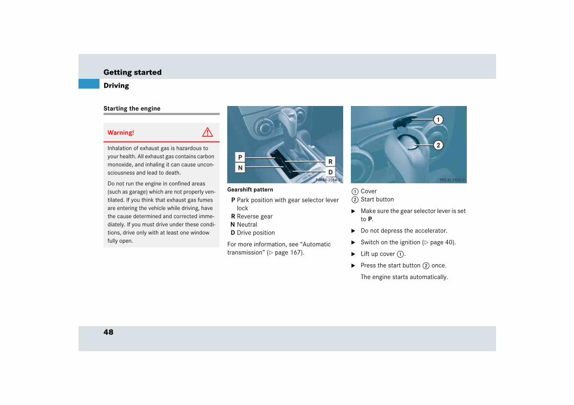
Gearshift pattern
P Park position with gear selector lever lock
R Reverse gearN NeutralD Drive position
For more information, see “Automatic transmission” (� page 167).
1 Cover2 Start button
� Make sure the gear selector lever is set to P.
� Do not depress the accelerator.
� Switch on the ignition (� page 40).
� Lift up cover 1.
� Press the start button 2 once.
The engine starts automatically.
Warning! G
Inhalation of exhaust gas is hazardous to your health. All exhaust gas contains carbon monoxide, and inhaling it can cause uncon-sciousness and lead to death.
Do not run the engine in confined areas (such as garage) which are not properly ven-tilated. If you think that exhaust gas fumes are entering the vehicle while driving, have the cause determined and corrected imme-diately. If you must drive under these condi-tions, drive only with at least one window fully open.
49
Getting started
Driving
� Close cover 1.
� Depress the brake pedal.
The gear selector lever lock is released.
For information on turning off the engine, see “Turning off the engine” (� page 58).
Starting difficulties
If the engine does not start as described, carry out the following steps:
� Turn the SmartKey in the starter switch to position 0 and repeat starting procedure (� page 48).
� Remember that extended starting at-tempts can drain the battery.
If the engine does not start after several starting attempts, there could be a mal-function in the engine electronics or in the fuel supply system.
� Notify an authorized Mercedes-Benz Center.
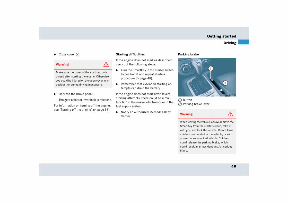
Parking brake
1 Button2 Parking brake lever
Warning! G
Make sure the cover of the start button is closed after starting the engine. Otherwise you could be injured on the open cover in an accident or during driving maneuvers.
Warning! G
When leaving the vehicle, always remove the SmartKey from the starter switch, take it with you, and lock the vehicle. Do not leave children unattended in the vehicle, or with access to an unlocked vehicle. Children could release the parking brake, which could result in an accident and/or serious injury.
50
Getting started
Driving
� Pull lever 2 upwards slightly, press re-lease knob 1 and move the lever down to the stop.
The warning lamp ; (USA only) or 3 (Canada only) in the instrument cluster goes out.
Driving
� Depress the brake pedal.
� Place the gear selector lever in position D or R.
� Release the brake pedal.
� Carefully depress the accelerator pedal.
Once the vehicle is in motion, the automat-ic central locking system engages.
After a cold start, the transmission engag-es at a higher revolution. This allows the catalytic converter to reach its operating temperature earlier.
Warning! G
It is dangerous to shift the gear selector le-ver out of P or N if the engine speed is high-er than idle speed. If your foot is not firmly on the brake pedal, the vehicle could accel-erate quickly forward or in reverse. You could lose control of the vehicle and hit someone or something. Only shift into gear when the engine is idling normally and when your right foot is firmly on the brake pedal.
Warning! G
On slippery road surfaces, never downshift in order to obtain braking action. This could result in drive wheel slip and reduced vehi-cle control. Your vehicle’s ABS will not pre-vent this type of loss of control.
!In order to avoid damage to the trans-mission:
� Wait for the gear selection process to complete before setting the vehi-cle in motion.
� Place the gear selector lever in position R or P only when the vehi-cle is stopped.
!If you hear a warning signal when driv-ing off, you have forgotten to release the parking brake.
Release the parking brake.
!Do not run cold engine at high engine speed. Running a cold engine at high engine speed may shorten the service life of the engine.

51
Getting started
Driving
Switching on the headlamps
Low beam headlamps
The exterior lamp switch is located on the dashboard to the left of the steering wheel.
Exterior lamp switch
1 Lights off2 Low beam headlamps on
� Turn switch to B.
For more information on headlamps, see “Lighting” (� page 105).
High beam
The combination switch is located on the left of the steering column.
Combination switch
1 High beam2 High beam flasher
� Push combination switch in direction of arrow 1.
The high beam indicator A in the instrument cluster comes on.
For more information on high beam, see “Combination switch” (� page 109).
!Simultaneously depressing the acceler-ator pedal and applying the brake re-duces engine performance and causes premature brake and drivetrain wear.
iYou can open a locked door from the inside. Open door only when conditions are safe to do so.
You can deactivate the automatic lock-ing using the control system (� page 135).
52
Getting started
Driving
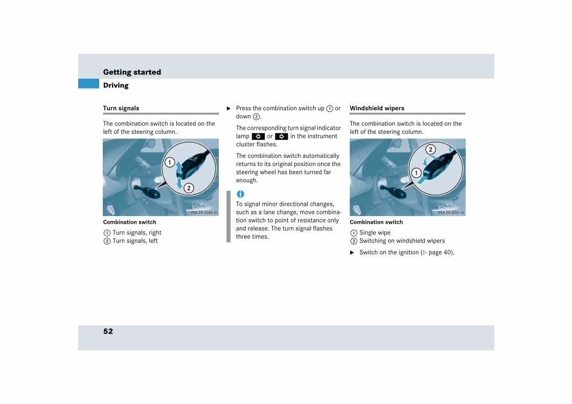
Turn signals
The combination switch is located on the left of the steering column.
Combination switch
1 Turn signals, right2 Turn signals, left
� Press the combination switch up 1 or down 2.
The corresponding turn signal indicator lamp L or K in the instrument cluster flashes.
The combination switch automatically returns to its original position once the steering wheel has been turned far enough.
Windshield wipers
The combination switch is located on the left of the steering column.
Combination switch
1 Single wipe2 Switching on windshield wipers
� Switch on the ignition (� page 40).
iTo signal minor directional changes, such as a lane change, move combina-tion switch to point of resistance only and release. The turn signal flashes three times.
53
Getting started
Driving
Switching on windshield wipers
� Turn the combination switch to the desired position depending on the intensity of the rain.
0 Windshield wipers off
I Intermittent wiping
II Normal wiper speed (goes to setting I when the car is standing still)
III Fast wiper speed (goes to setting I when the car is standing still)
Intermittent wiping
� Set the wiper switch to position I.
Single wipe
� Press combination switch briefly in direction of arrow 1.
The windshield wipers wipe one time without washer fluid.
Wiping with windshield washer fluid
� Push combination switch in direction of arrow 1 past the resistance point.
The windshield wipers operate with washer fluid.
For information on filling up the washer reservoir, see “Windshield washer system and headlamp cleaning system” (� page 251).
iIntermittent wiping interval is dependent on wetness of windshield. After the initial wipe, pauses between wipes are automatically controlled by the rain sensor.
!Do not leave windshield wipers in intermittent setting when the vehicle is taken to an automatic car wash or during windshield cleaning. Wipers will operate in the presence of water sprayed on the windshield, and wipers may be damaged as a result.
The switch should not be left in intermittent setting as the wipers will wipe the windshield once every time the engine is started. Dust that accumulates on the windshield might scratch the glass and/or damage the wiper blades when wiping occurs on a dry windshield.

54
Getting started
Driving
Problems while driving
The engine runs erratically and misfires
� An ignition cable may be damaged.
� The engine electronics may not be op-erating properly.
� Unburned gasoline may have entered the catalytic converter and damaged it.
� Give very little gas.
� Have the problem repaired by an au-thorized Mercedes-Benz Center as soon as possible.
!If anything blocks the windshield wipers (leaves, snow, etc.), switch them off immediately.
� For safety reasons, withdraw SmartKey from starter switch before attempting to remove any blockage.
� The hood must be opened (� page 243) before folding the wiper arms away from the wind-screen. You could otherwise dam-age the hood and/or the wiper arm.
� Remove blockage.
� Turn the windshield wipers on again.
If windshield wipers fail to function at all in switch position I,
� set the combination switch to the next highest wiper speed
� have the windshield wipers checked at the nearest authorized Mercedes-Benz Center
55
Getting started
Driving
The coolant temperature is above 248°F (120°C)
The coolant is too hot and is no longer cooling the engine.
� Stop the vehicle as soon as possible and turn off the engine. Allow engine and coolant to cool.
� Check the coolant level and add cool-ant if necessary (� page 249).
In case of accident
If the vehicle is leaking gasoline:
� Do not start the engine under any cir-cumstances.
� Notify local fire and/or police authori-ties.
If the extent of the damage cannot be de-termined:
� Notify an authorized Mercedes-Benz Center.
If no damage can be determined on the
� major assemblies
� fuel system
� engine mount:
� Start the engine in the usual manner.

56
Getting started
Parking and locking
You have now completed your first drive. You have properly stopped and parked your vehicle. End your drive as follows.
Parking brake
1 Parking brake lever
� Pull parking brake lever 1 up as many notches as possible.
When the engine is running, the warning lamp ; (USA only) or 3 (Canada only) in the instrument cluster will be illuminated.
Warning! G
With the engine not running, there is no power assistance for the brake and steering system. In this case, it is important to keep in mind that a considerably higher degree of effort is necessary to brake and steer the vehicle.
Warning! G
Do not park this vehicle in areas where com-bustible materials such as grass, hay or leaves can come into contact with the hot exhaust system, as these materials could be ignited and cause a vehicle fire.
To reduce the risk of personal injury as a re-sult of vehicle movement, before turning off the engine and leaving the vehicle always:
� Keep right foot on brake pedal.
� Pull the parking brake lever up as many notches as possible.
� Move the gear selector lever to position P.
� Slowly release brake pedal.
� When parked on an incline, turn front wheels towards the road curb.
� Turn the SmartKey in the starter switch to position 0 and remove the SmartKey from the starter switch.
� Take the SmartKey and lock the vehicle when leaving.
57
Getting started
Parking and locking
Switching off headlamps
� Turn the exterior lamp switch to M (� page 51).
For more information on headlamps, see “Lighting” (� page 105).
Warning! G
When leaving the vehicle, always remove the SmartKey from the starter switch, take it with you, and lock the vehicle. Do not leave children unattended in the vehicle, or with access to an unlocked vehicle. Children could release the parking brake and/or move the gear selector lever from position P, either of which could result in an accident and/or serious injury.
Warning! G
Getting out of your vehicle with the gear se-lector lever not fully engaged in position P is dangerous. Also, when parked on an incline, position P alone may not prevent your vehi-cle from moving, possibly hitting people or objects.
Always set the parking brake in addition to shifting to position P (� page 48).
When parked on an incline, turn front wheels towards the road curb.
58
Getting started
Parking and locking
Turning off the engine
� Place the gear selector lever in position P.
� Turn the SmartKey in the starter switch to position 0 and remove the SmartKey from the starter switch.
The immobilizer is activated.
� Press the seat belt release button (� page 46).
Allow the retractor to completely rewind the seat belt by guiding the latch plate.
� After exiting the vehicle, press the lock button ‹ on the SmartKey (� page 38).
With the hood, trunk and all doors closed, all turn signal lamps flash three times. The anti-theft alarm system is armed.
For more information, see “Locking and unlocking” (� page 96).
iAlways set the parking brake in addi-tion to shifting to position P.
On slopes, turn the front wheels to-wards the road curb.
iThe SmartKey can only be removed from the starter switch with the gear selector lever in position P.
iWith the SmartKey removed and the driver’s door open, a warning sounds if the vehicle’s exterior lamps are not switched off.
Warning! G
To prevent possible personal injury, always keep hands and fingers away from the door openings when closing the doors. Be espe-cially careful when small children are around.
Before closing doors, make sure there is no possibility of someone getting caught in a door during closing.
Warning! G
When leaving the vehicle, always remove the SmartKey from the starter switch, take it with you, and lock the vehicle. Do not leave children unattended in the vehicle, or with access to an unlocked vehicle. Unsuper-vised use of vehicle equipment may cause an accident and/or serious personal injury.

59
Safety and Security
Occupant safety
Panic alarm
Driving safety systems
Performance enhancement system
Anti-theft systems

62
Safety and Security
Occupant safety
In this section you will learn the most im-portant facts about the restraint systems of the vehicle.
The restraint systems are
� Seat belts
� Emergency tensioning device
� Airbags
� Child seats
� Child seat recognition
As independent systems, their protective effects work in conjunction with each other.
The 1 indicator lamp in the instrument cluster comes on
� for about four seconds when you turn the SmartKey in the starter switch to position 1. It then goes out briefly, comes on again and remains lit until you start the engine or turn the SmartKey to position 2.
� for about four seconds when you turn the SmartKey in the starter switch to position 2.
� for about four seconds when you start the engine using the start button (� page 48).
The 1 indicator lamp goes out shortly after you start the engine. This shows that the restraint systems are operational.
A malfunction in the system has been detected if the 1 indicator lamp
� fails to go out after approximately four seconds
� does not come on at all
� comes on after the engine was started or while driving
For more information, see the “Practical hints” section (� page 302).
iFor information on infants and children traveling with you in the vehicle and re-straint systems for infants and chil-dren, see “Children in the vehicle” (� page 72).
63
Safety and Security
Occupant safety
AirbagsWarning! G
In the event that the 1 indicator lamp comes on during driving or does not come on at all, the SRS self-check has detected a malfunction. For your safety, we strongly recommend that you visit an authorized Mercedes-Benz Center immediately to have the system checked, otherwise the SRS may not be activated when needed in an acci-dent, which could result in serious or fatal injury, or it might deploy unexpectedly and unnecessarily which could also result in injury.
In addition, improper repair work creates a risk of rendering the SRS inoperative or causing unintended airbag deployment. Work on the SRS must therefore only be per-formed by qualified technicians. Contact an authorized Mercedes-Benz Center.
Warning! G
Airbags are designed to reduce the potential of injury and fatality in certain frontal im-pacts (front airbags, knee airbags) or side impacts (head-thorax airbags). However, no system available today can totally eliminate injuries and fatalities.
The activation of the airbags temporarily re-leases a small amount of dust from the air-bags. This dust, however, is neither injurious to your health, nor does it indicate a fire in the vehicle. The dust might cause some tem-porary breathing difficulty for people with asthma or other breathing trouble. To avoid this, you may wish to get out of the vehicle as soon as it is safe to do so. If you have any breathing difficulty but cannot get out of the vehicle after the airbag inflates, then get fresh air by opening a window or door.
Warning! G
To reduce the risk of injury when the front airbags inflate, it is very important for the driver and front passenger to always be in a properly seated position and to wear your seat belts.
For maximum protection in the event of a collision always be in normal seated position with your back against the backrest. Fasten your seat belt and make sure that it is prop-erly positioned on your body (� page 45).
Since the airbag inflates with considerable speed and force, a proper seating and hands on steering wheel position will help to keep you at a safe distance from the airbag. Occupants who are unbelted, out of position or too close to the airbag can be seriously in-jured by an airbag as it inflates with great force in the blink of an eye:
� Sit properly belted in a nearly upright position with your back against the seat backrest. ��
64
Safety and Security
Occupant safety
� Adjust the driver seat as far as possible rearward, still permitting proper opera-tion of vehicle controls. The distance from the center of the driver’s breast-bone to the center of the airbag cover on the steering wheel must be at least ten inches (25 cm) or more. You should be able to accomplish this by a combina-tion of adjustments to the seat and steering wheel. If you have any prob-lems, please see an authorized Mercedes-Benz Center.
� Do not lean with your head or chest close to the steering wheel or dash-board.
� Keep hands on the outside of steering wheel rim. Placing hands and arms in-side the rim can increase the risk and potential severity of hand/arm injury when driver front airbag inflates.
� Adjust the front passenger seat as far as possible rearward from the dashboard when the seat is occupied.
� Occupants, especially children, should never lean their heads in the area of the door where the head-thorax airbag in-flates. This could result in serious inju-ries or death should the airbag be triggered. Always sit nearly upright, properly use the seat belts and appropri-ate size infant or child restraint system.
� Children 12 years old and under must never ride in this vehicle, except in a Mercedes-Benz authorized BabySmartTM1 compatible child seat, which operates with the BabySmartTM system installed in the vehicle to deacti-vate the passenger front airbag when it is properly installed. Otherwise they will be struck by the airbag when it inflates in a crash. If this happens, serious or fa-tal injury will result.
1 BabySmartTM is a trademark of Siemens Automotive Corp.
Failure to follow these instructions can result in severe injuries to you or other occupants.
If you sell your vehicle, it is important that you make the buyer aware of this safety information. Be sure to give the buyer this Operator’s Manual.
��
65
Safety and Security
Occupant safety
Warning! G
Should you choose to place a child 12 years old or under in the passenger seat of your vehicle, you must properly use a BabySmartTM child restraint which will turn off the passenger front airbag (� page 72). BabySmartTM will not, however, turn off any side impact airbag.
It should be noted, however, that there is a possibility for a head-thorax airbag related injury if occupants, especially children, are not properly seated or restrained when next to a head-thorax airbag which needs to de-ploy rapidly in a side impact in order to do its job.
To help avoid the possibility of injury, please follow these guidelines:
(1) Occupants, especially children, should never place their bodies or lean their heads in the area of the door where the head-thorax airbag inflates. This could result in serious injuries or death should the head-thorax airbag be activated.
(2) Always sit nearly upright, properly use the seat belts and use an appropriately sized infant or child restraint system for all children 12 years old or under.
(3) Always wear seat belts properly.
If you believe that, even with the use of these guidelines, it would be safer for your passenger seat occupants to have the pas-senger side head-thorax airbag deactivated, then deactivation can be accomplished upon your written election to do so at an au-thorized Mercedes-Benz Center at an addi-tional cost. Please contact your local authorized Mercedes-Benz Center or call our Customer Assistance Center at 1-800-FOR-MERCedes (1-800-367-6372) for details.

66
Safety and Security
Occupant safety
iAirbags are designed to activate only in certain frontal impacts (front airbags, knee airbags) and side impacts (head-thorax airbags) which exceed preset thresholds. Only during these types of impacts, if of sufficient severi-ty to meet the deployment threshold, will they provide their supplemental protection.
The driver and passengers should al-ways wear their seat belts. Otherwise it is not possible for the airbags to pro-vide their intended supplemental pro-tection.
In cases of other frontal impacts, an-gled impacts, roll-overs, other side im-pacts, rear collisions, or other accidents and impacts below airbag deployment thresholds, the airbags will not be activated. The driver and pas-senger will then be protected to the ex-tent possible by a properly fastened seat belt.
We caution you not to rely on the pres-ence of the airbags in order to avoid wearing your seat belt.
Your vehicle was originally equipped with airbags which are designed to ac-tivate in certain impacts exceeding a preset threshold to reduce the poten-tial and severity of injury. It is important to your safety and that of your passen-ger that you replace deployed airbags and repair any malfunctioning airbags to ensure that the vehicle will continue to provide supplemental crash protec-tion for occupants.
67
Safety and Security
Occupant safety
Safety guidelines for the seat belt, emergency tensioning device and airbag
When you sell your vehicle, we strongly urge you to give notice to the subsequent owner that it is equipped with an SRS by alerting them to the applicable section in the Operator’s Manual.
Warning! G
� Damaged seat belts or belts that were highly stressed in an accident must be replaced and their anchoring points must also be checked. Only use belts in-stalled or supplied by an authorized Mercedes-Benz Center.
� Airbags and ETDs (Emergency Tension-ing Devices) are designed to function on a one-time-only basis. An airbag or ETD that was activated must be replaced.
� No modifications of any kind may be made to any components or wiring of the SRS. This includes changing or re-moving any component or part of the SRS, the installation of additional trim material, badges, etc. over the steering wheel hub, passenger front airbag cov-er, knee airbag covers or door trim pan-els, and installation of additional
electrical/electronic equipment on or near SRS components and wiring. Keep area between airbags and occupants free from objects (e.g. packages, purs-es, umbrellas, etc.).
� Do not pass belts over sharp edges. They could tear.
� Do not make any modification that could change the effectiveness of the belts.
� Do not bleach or dye seat belts as this may severely weaken them. In a crash, they may not be able to provide adequate protection.
� Airbag system components will be hot after an airbag has inflated. Do not touch.
� Never place your feet on the instrument panel, dashboard, or on the seat. Always keep both feet on the floor in front of the seat.
� In addition, improper repair work on the SRS creates a risk of rendering the SRS inoperative or causing unintended air-bag deployment. Work on the SRS must therefore only be performed by qualified technicians. Contact an authorized Mercedes-Benz Center.
� For your protection and the protection of others, when scrapping the airbag unit or emergency tensioning device, our safety instructions must be fol-lowed. These instructions are available from your authorized Mercedes-Benz Center.
� Given the considerable deployment speed and the textile structure of the airbags, there is the possibility of abra-sions or other injuries resulting from air-bag deployment.
68
Safety and Security
Occupant safety
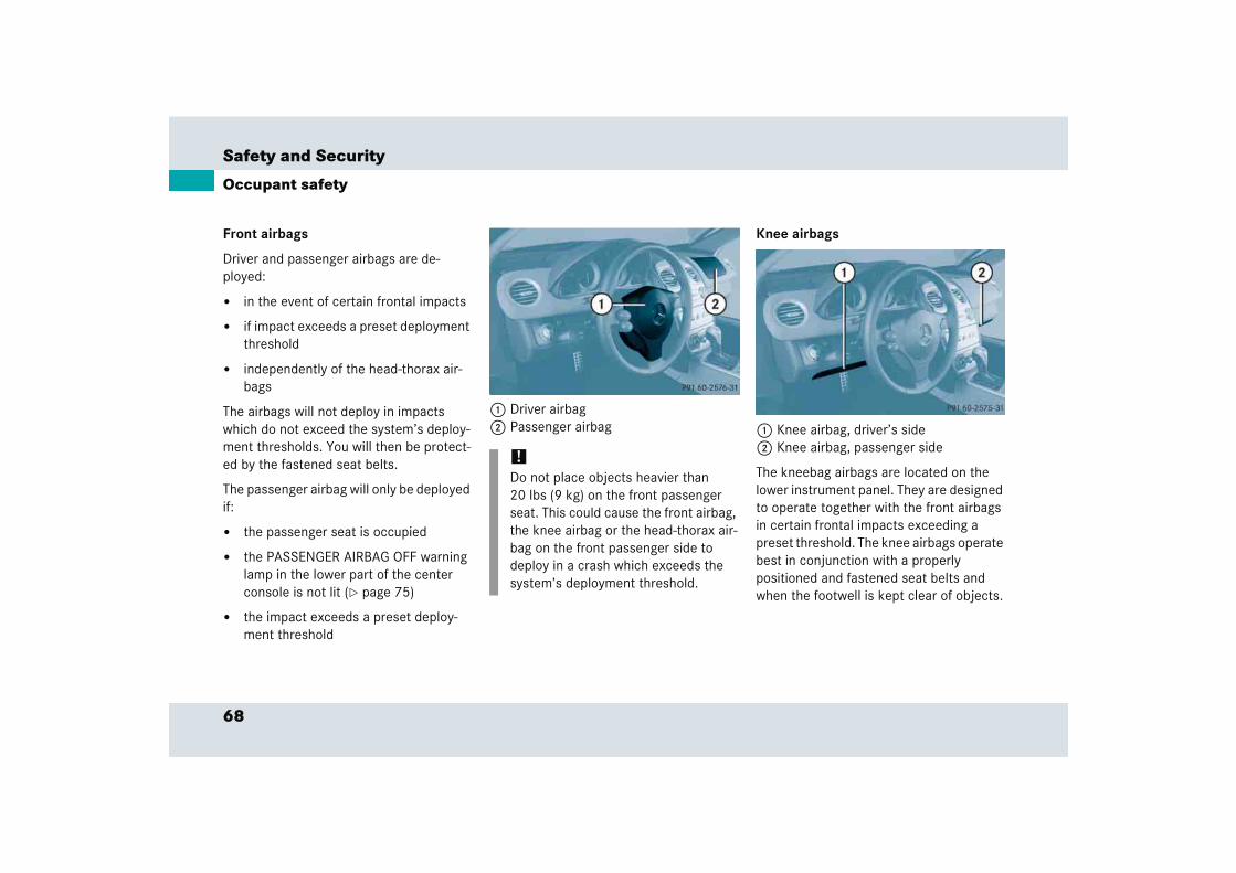
Front airbags
Driver and passenger airbags are de-ployed:
� in the event of certain frontal impacts
� if impact exceeds a preset deployment threshold
� independently of the head-thorax air-bags
The airbags will not deploy in impacts which do not exceed the system’s deploy-ment thresholds. You will then be protect-ed by the fastened seat belts.
The passenger airbag will only be deployed if:
� the passenger seat is occupied
� the PASSENGER AIRBAG OFF warning lamp in the lower part of the center console is not lit (� page 75)
� the impact exceeds a preset deploy-ment threshold
1 Driver airbag2 Passenger airbag
Knee airbags
1 Knee airbag, driver’s side2 Knee airbag, passenger side
The kneebag airbags are located on the lower instrument panel. They are designed to operate together with the front airbags in certain frontal impacts exceeding a preset threshold. The knee airbags operate best in conjunction with a properly positioned and fastened seat belts and when the footwell is kept clear of objects.
!Do not place objects heavier than 20 lbs (9 kg) on the front passenger seat. This could cause the front airbag, the knee airbag or the head-thorax air-bag on the front passenger side to deploy in a crash which exceeds the system’s deployment threshold.
69
Safety and Security
Occupant safety
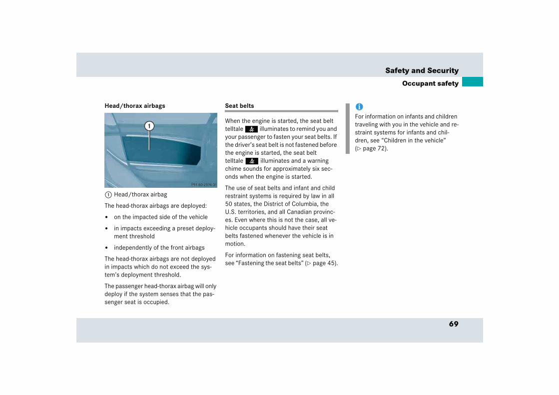
Head/thorax airbags
1 Head/thorax airbag
The head-thorax airbags are deployed:
� on the impacted side of the vehicle
� in impacts exceeding a preset deploy-ment threshold
� independently of the front airbags
The head-thorax airbags are not deployed in impacts which do not exceed the sys-tem’s deployment threshold.
The passenger head-thorax airbag will only deploy if the system senses that the pas-senger seat is occupied.
Seat belts
When the engine is started, the seat belt telltale < illuminates to remind you and your passenger to fasten your seat belts. If the driver’s seat belt is not fastened before the engine is started, the seat belt telltale < illuminates and a warning chime sounds for approximately six sec-onds when the engine is started.
The use of seat belts and infant and child restraint systems is required by law in all 50 states, the District of Columbia, the U.S. territories, and all Canadian provinc-es. Even where this is not the case, all ve-hicle occupants should have their seat belts fastened whenever the vehicle is in motion.
For information on fastening seat belts, see “Fastening the seat belts” (� page 45).
iFor information on infants and children traveling with you in the vehicle and re-straint systems for infants and chil-dren, see “Children in the vehicle” (� page 72).
70
Safety and Security
Occupant safety
Warning! G
Always fasten your seat belt before driving off. Always make sure your passenger is properly restrained, even pregnant women.
Failure to wear and properly fasten and po-sition your seat belt greatly increases your risk of injuries and their likely severity in an accident. You and your passenger should al-ways wear seat belts.
If you are ever in an accident, your injuries can be considerably more severe without your seat belt properly buckled. Without your seat belt buckled, you are much more likely to hit the interior of the vehicle or be ejected from it. You can be seriously injured or killed.
In the same crash, the possibility of injury or death is lessened if you are wearing your seat belt. The airbags can only provide the protection they were designed to afford if the occupants are using their seat belts (� page 69).
Warning! G
Never ride in a moving vehicle with the seat backrest in an excessively reclined position as this can be dangerous. You could slide under the seat belt in a collision. If you slide under it, the belt would apply force at the ab-domen or neck. That could cause serious or even fatal injuries. The seat backrest and seat belt provide the best restraint when the wearer is in a nearly upright position and the belt is properly positioned on the body.
Warning! G
Never let more people ride in the vehicle than there are seat belts available. Be sure everyone riding in the vehicle is correctly re-strained with a separate seat belt. Never use a seat belt for more than one person at a time.
Warning! G
Damaged seat belts or belts that were highly stressed in an accident must be replaced and their anchoring points must also be checked.
Only use seat belts which have been ap-proved by Mercedes-Benz.
Do not make any modifications to the seat belts. This can lead to failure of the seat belts.
Do not bleach or dye seat belts as this may severely weaken them. In a crash, they may not be able to provide adequate protection.
Have all work carried out only by qualified technicians. Contact an authorized Mercedes-Benz Center.
71
Safety and Security
Occupant safety
Warning! G
USE SEAT BELTS PROPERLY
� Seat belts can only work when used properly. Never wear seat belts in any other way than as described in this sec-tion, as that could result in serious inju-ries in case of an accident.
� Each occupant should wear their seat belt at all times, because seat belts help reduce the likelihood of and potential severity of injuries in accidents, includ-ing rollovers. The integrated restraint system includes SRS (driver airbag, pas-senger airbag, knee airbags, head-tho-rax airbags) and ETD (seat belt emergency tensioning device). The sys-tem is designed to enhance the protec-tion offered to properly belted occupants in certain frontal (front air-bags, knee airbags and ETD) and side (head-thorax airbags and ETD) impacts which exceed preset deployment thresholds.
� Never wear the shoulder belt under your arm, against your neck or off your shoul-der. In a crash, your body would move too far forward. That would increase the chance of head and neck injuries. The belt would also apply too much force to the ribs or abdomen, which could se-verely injure internal organs such as your liver or spleen.
� Never wear belts over rigid or breakable objects in or on your clothing, such as eyeglasses, pens, keys, etc., as these might cause injuries.
� Position the lap belt as low as possible on your hips and not across the abdo-men. If the belt is positioned across your abdomen, it could cause serious injuries in a crash.
� Never use a seat belt for more than one person at a time. Do not fasten a seat belt around a person and another per-son or other objects.
� Belts should not be worn twisted. In a crash, you wouldn’t have the full width of the belt to manage impact forces. The twisted belt against your body could cause injuries.
� Pregnant women should also use a lap-shoulder belt. The lap belt portion should be positioned as low as possible on the hips to avoid any possible pres-sure on the abdomen.
� Never place your feet on the instrument panel, dashboard or on the seat. Always keep both feet on the floor in front of the seat.
72
Safety and Security
Occupant safety
Emergency tensioning device (ETD), seat belt force limiter
The seat belts are equipped with emergency tensioning devices and belt force limiters.
The ETD is designed to activate in the following cases when the seat belts are fastened:
� in frontal or rear-end impacts exceed-ing a preset severity level
� if the restraint systems are operational and functioning correctly, see 1 in-dicator lamp (� page 62).
In an impact, emergency tensioning devic-es remove slack from the belts in such a way that the seat belts fit more snugly against the body. Belt force limiters reduce the force exerted by the seat belts on occupants during a crash.
Children in the vehicle
If an infant or child is traveling with you in the vehicle:
� Secure the child using an infant or child restraint appropriate to the age and size of the child.
� Make sure the infant or child is proper-ly secured at all times while the vehicle is in motion.
Infant and child restraint seats and infor-mation on choosing an appropriate re-straint system can be obtained from any Mercedes-Benz Center.
Warning! G
An emergency tensioning device (ETD) that was activated must be replaced.
When disposing of the emergency tension-ing device, our safety instructions must be followed. These are available at your autho-rized Mercedes-Benz Center.
!Do not place objects heavier than 20 lbs (9 kg) on the front passenger seat. This could cause the front or side impact airbag on the passenger side and, with the seat belt fastened to se-cure the object, the ETD to deploy in a crash which exceeds the system’s de-ployment threshold.
73
Safety and Security
Occupant safety
Infant and child restraint systems
Only use a BabySmartTM1compatible child restraint for the front passenger seat in this vehicle.
We recommend all infants and children be properly restrained at all times while the vehicle is in motion.
The passenger lap-shoulder belt has a spe-cial seat belt retractor for the secure fas-tening of child restraints.
To fasten a child restraint follow child re-straint instructions for mounting. Then pull the shoulder belt out completely and let it retract. During the seat belt retraction a ratcheting sound can be heard to indicate that the special seat belt retractor is acti-vated. The belt is now locked. Push down on child restraint to take up any slack.
To deactivate, release seat belt buckle and let seat belt retract completely. The seat belt can again be used in the usual manner.
1 BabySmartTM is a trademark of Siemens Automotive Corp.
Warning! G
Never release the seat belt buckle while the vehicle is in motion, since the special seat belt retractor will be deactivated.
!The use of infant or child restraints is required by law in all 50 states, the Dis-trict of Columbia, the U.S. territories, and all Canadian provinces.
Infants and small children should be seated in an appropriate infant or child restraint system which is properly secured by a lap-shoulder belt and top tether strap that complies with U.S. Federal Motor Vehicle Safety Standard 213 and Canadian Motor Vehicle Safety Standard 213.
A statement by the child restraint man-ufacturer of compliance with this stan-dard can be found on the instruction label on the restraint and in the instruc-tion manual provided with the restraint.
74
Safety and Security
Occupant safety
When using any infant or child restraint system, be sure to carefully read and follow all manufacturer’s instructions for installation and use.
Please read and observe warning labels affixed to inside of vehicle and to infant or child restraints.
Warning! G
Children 12 years old and under must never ride in this vehicle, except in a Mercedes-Benz authorized BabySmartTM compatible child seat, which operates with the BabySmartTM system installed in the ve-hicle to deactivate the passenger front air-bag when it is properly installed. Otherwise they will be struck by the airbag when it in-flates in a crash. If this happens, serious or fatal injury will result.
Infants and small children must be seated in an appropriate BabySmartTM compatible in-fant or child restraint system, which is prop-erly secured with the vehicle’s seat belt and top tether strap, fully in accordance with the child seat manufacturer’s instructions.
Infants and small children should never share a seat belt with another occupant. During an accident, they could be crushed between the occupant and seat belt.
A child’s risk of serious or fatal injuries is significantly increased if the child restraints are not properly secured in the vehicle and the child is not properly secured in the child restraint.
Adjust the passenger seat as far as possible rearward from the dashboard when the seat is occupied.
Warning! G
Children too big for child restraint systems should use regular seat belts. Position the shoulder belt across chest and shoulder, not face or neck. A booster seat may be neces-sary to achieve proper belt positioning for children from 41 lbs until they reach a height where a lap/shoulder belt fits properly without a booster.
When the child restraint is not in use, re-move it from the vehicle or secure it with the seat belt to prevent the child restraint from becoming a projectile in the event of an accident.
Do not leave children unattended in the vehicle; even if the children are secured in a child restraint system. Unsupervised children in a child restraint system may use vehicle equipment and cause an accident and/or serious personal injury.

75
Safety and Security
Occupant safety
BabySmartTM1 airbag deactivation system
1 PASSENGER AIRBAG OFF indicator lamp
Special BabySmartTM compatible child seats, designed for use with the Mercedes-Benz system and available at any authorized Mercedes-Benz Center, are required for use with the BabySmartTM air-bag deactivation system. With the special child seat properly installed, the passenger front airbag and the passenger knee airbag will not deploy.
The PASSENGER AIRBAG OFF indicator lamp 1 located on the lower part of the center console will be illuminated, except with the SmartKey removed or in starter switch position 0.
Self-test BabySmartTM without special child seat installed
After turning the SmartKey in the starter switch to position 1 or 2, the PASSENGER AIRBAG OFF indicator lamp comes on for approximately six seconds and then goes out.
If the PASSENGER AIRBAG OFF indicator lamp should not come on or is continuous-ly lit, the system is not functioning. You must see an authorized Mercedes-Benz Center before seating any child on the front passenger seat.
1 BabySmartTM is a trademark of Siemens Automotive Corp.
iThe system does not deactivate the head-thorax airbag and the emergency tensioning device.
76
Safety and Security
Occupant safety
Warning! G
The BabySmartTM1 airbag deactivation sys-tem will ONLY work with a special child seat designed to operate with it. It will not work with child seats which are not BabySmartTM compatible.
Never place anything between seat cushion and child seat (e.g. pillow), since it reduces the effectiveness of the deactivation sys-tem. The bottom of the child seat must make full contact with the passenger seat cushion. An incorrectly mounted child seat could cause injuries to the child in case of an accident, instead of protecting the child.
Follow the manufacturer’s instructions for installation of special child seats.
1 BabySmartTM is a trademark of Siemens Automotive Corp.
Warning! G
When using a BabySmartTM compatible child seat on the passenger seat, the pas-senger front airbag will not deploy only if the PASSENGER AIRBAG OFF indicator lamp (� page 75) remains illuminated.
Please be sure to check the PASSENGER AIRBAG OFF indicator lamp every time you use the special system child seat. Should the PASSENGER AIRBAG OFF indicator lamp go out while the restraint is installed, please check installation. If the PASSENGER AIR-BAG OFF indicator lamp remains out, do not use the BabySmartTM restraint to transport children on the passenger seat until the sys-tem has been repaired.
Warning! G
Do not place powered-on laptops, cell phones and like electronic devices on the front passenger seat. Signals from such de-vices may interfere with the BabySmartTM system. Such signal interference may cause the PASSENGER AIRBAG OFF indicator lamp (� page 75) not to come on during self-test or be continuously lit, indicating that the system is not functioning.

77
Safety and Security
Occupant safety
Installation of infant and child restraint systems
This vehicle is equipped with a tether an-chorage for a top tether strap behind the passenger seat.
1 Cover of anchorage ring
� To have better access to the anchorage ring, move the passenger seat forward (� page 42).
� Remove cover 1 in direction of the ar-row from anchorage ring 3.
� Guide tether strap according to the child restraint manufacturer’s instruc-tions.
Make sure the tether strap is not twisted.
2 Hook3 Anchorage ring
� Securely fasten hook 2, which is part of the tether strap, to anchorage ring 3.
� Move the passenger seat back as far to the rear as possible.
Once the top tether anchorage hook is attached, the child restraint itself can be secured.
� Properly secure the child restraint us-ing the passenger seat lap/shoulder belt (� page 73) and tether anchorage for top tether strap, fully in accordance with the child restraint manufacturer’s instructions.
� Tighten the top tether strap according to the child restraint manufacturer’s in-structions.
� Reinstall cover 1 after removing the tether strap.
iFor safety, make sure the hook has attached to the ring beyond the safety catch, as illustrated.

78
Safety and Security
Panic alarm
An audible alarm and flashing exterior lamps will operate for approximately 3 minutes.
1 Â button
Activating
� Press and hold button 1 for at least one second.
Deactivating
� Press button 1 again.
or
� Insert SmartKey in starter switch.
iUSA only: This device complies with Part 15 of the FCC Rules. Operation is subject to the following two conditions:
(1) This device may not cause harmful interference, and
(2) this device must accept any inter-ference received, including interfer-ence that may cause undesired operation.
Any unauthorized modification to this device could void the user’s authority to operate the equipment.
iCanada only:This device complies with RSS-210 of Industry Canada. Operation is subject to the following two conditions:
(1) This device may not cause interfer-ence, and
(2) this device must accept any inter-ference received, including interfer-ence that may cause undesired operation of the device.
Any unauthorized modification to this device could void the user’s authority to operate the equipment.

79
Safety and Security
Driving safety systems
� Driving safety systemsIn this section you will find information on the following driving safety systems:
� ABS (Antilock Brake System)
� BAS (Brake Assist System)
� ESP (Electronic Stability Program)
� SBC (Sensotronic Brake Control)
ABS
The Antilock Brake System (ABS) regulates the brake pressure so that the wheels do not lock during braking. This allows you to maintain the ability to steer your vehicle.
The ABS is functional above a speed of ap-proximately 5 mph (8 km/h) independent of road surface conditions.
On slippery road surfaces, the ABS will re-spond even to light brake pressure.
iIn winter operation, the maximum ef-fectiveness of the ABS, the BAS, the ESP, and the SBC is only achieved with winter tires (M+S tires) or snow chains as required.
Warning! G
The following factors increase the risk of ac-cidents:
� Excessive speed, especially in turns
� Wet and slippery road surfaces
� Following another vehicle too closely
The ABS, BAS, ESP, and SBC cannot reduce this risk.
Always adjust your driving style to the pre-vailing road and weather conditions.
Warning! G
Do not pump the brake pedal. Use firm, steady brake pedal pressure instead. Pump-ing the brake pedal defeats the purpose of the ABS and significantly reduces braking effectiveness.
80
Safety and Security
Driving safety systems
The - indicator lamp in the instrument cluster comes on (� page 29) when you switch on the ignition. It goes out when the engine is running.
Braking
If the ABS activates during braking, the ABS/ESP warning lamp v in the instru-ment cluster dial flashes. Because of the SBC brake system, you will not feel any pulsation in the brake pedal.
� Keep firm and steady pressure on the brake pedal.
Continuous, steady brake pedal pressure yields the advantages provided by the ABS, namely braking power and the ability to steer the vehicle.
The ABS/ESP warning lamp v flashes whenever the ABS is activated which can be an indication of hazardous road condi-tions and functions as a reminder to take extra care while driving.
Emergency brake maneuver
� Keep continuous, full pressure on the brake pedal.
For more information, see the “Practical hints” section (� page 297).
Warning! G
The ABS cannot prevent the natural laws of physics from acting on the vehicle, nor can it increase braking or steering efficiency be-yond that afforded by the condition of the vehicle brakes and tires or the traction. The ABS cannot prevent accidents, including those resulting from excessive speed in turns, following another vehicle too closely, or hydroplaning. Only a safe, attentive, and skillful driver can prevent accidents. The ca-pabilities of an ABS equipped vehicle must never be exploited in a reckless or danger-ous manner which could jeopardize the us-er’s safety or the safety of others.

81
Safety and Security
Driving safety systems
BAS
The Brake Assist System (BAS) operates in emergency situations. If you apply the brakes very quickly, the BAS automatically provides full brake boost thereby potential-ly reducing the braking distance. Apply continuous full braking pressure until the emergency braking situation is over. The ABS will prevent the wheels from locking.
When you release the brake pedal the brakes function again as normal. The BAS is then deactivated.
ESP
The Electronic Stability Program (ESP) is operational as soon as the engine is run-ning and monitors the vehicle’s traction (force of adhesive friction between the tires and the road surface) and handling.
The ESP recognizes when a wheel is spinning or if the vehicle starts to skid. By applying brakes to the appropriate wheel and by limiting the engine output, the ESP works to stabilize the vehicle. The ESP is especially useful while driving off and on wet or slippery road surfaces. The ESP also stabilizes the vehicle during braking ma-neuvers.
The ABS/ESP warning lamp v in the in-strument cluster (� page 29) flashes when the ESP is engaged.
The ABS/ESP warning lamp v in the instrument (� page 28) cluster comes on when you switch on the ignition. It goes out when the engine is running.
Warning! G
BAS cannot prevent the natural laws of physics from acting on the vehicle, nor can it increase braking efficiency beyond that af-forded by the condition of the vehicle brakes and tires or the traction. The BAS cannot prevent accidents, including those resulting from excessive speed in turns, following an-other vehicle too closely, or hydroplaning. Only a safe, attentive, and skillful driver can prevent accidents. The capabilities of a BAS equipped vehicle must never be exploited in a reckless or dangerous manner which could jeopardize the user’s safety or the safety of others.
82
Safety and Security
Driving safety systems
For more information, see the “Practical hints” section (� page 297).
Warning! G
Never switch off the ESP when you see the ABS/ESP warning lamp v flashing in the instrument cluster. In this case proceed as follows:
� While driving off, apply as little throttle as possible.
� While driving, ease up on the accelera-tor.
� Adapt your speed and driving style to the prevailing road conditions.
Failure to observe these guidelines could cause the vehicle to skid.
The ESP cannot prevent accidents resulting from excessive speed.
Warning! G
The ESP cannot prevent the natural laws of physics from acting on the vehicle, nor can it increase the traction afforded. The ESP cannot prevent accidents, including those resulting from excessive speed in turns, or hydroplaning. Only a safe, attentive, and skillful driver can prevent accidents. The ca-pabilities of an ESP equipped vehicle must never be exploited in a reckless or danger-ous manner which could jeopardize the user’s safety or the safety of others.
!Because of the ESP’s automatic opera-tion, the engine must be shut off (SmartKey in starter switch position 0 or 1) when
� the parking brake is being tested on a brake test dynamometer
� the vehicle is towed with the front axle raised
Active braking action through the ESP may otherwise seriously damage the brake system.
The ESP will only function properly if you use wheels of the recommended tire size (� page 369).
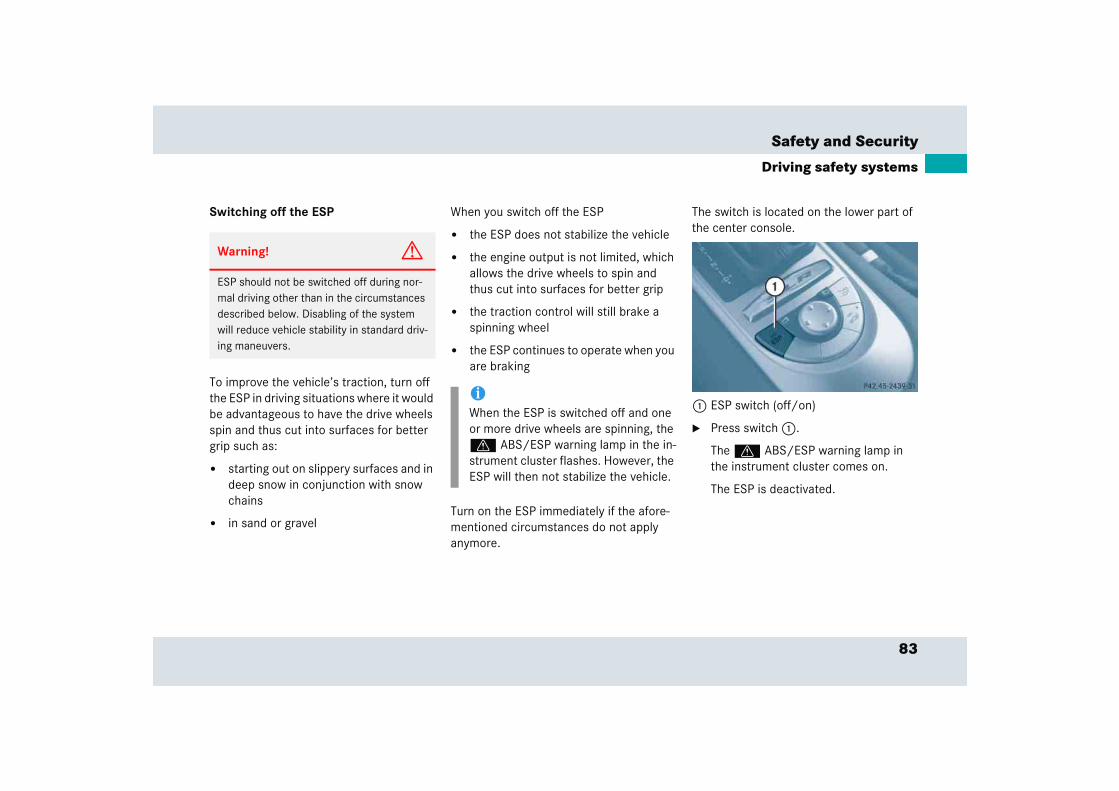
83
Safety and Security
Driving safety systems
Switching off the ESP
To improve the vehicle’s traction, turn off the ESP in driving situations where it would be advantageous to have the drive wheels spin and thus cut into surfaces for better grip such as:
� starting out on slippery surfaces and in deep snow in conjunction with snow chains
� in sand or gravel
When you switch off the ESP
� the ESP does not stabilize the vehicle
� the engine output is not limited, which allows the drive wheels to spin and thus cut into surfaces for better grip
� the traction control will still brake a spinning wheel
� the ESP continues to operate when you are braking
Turn on the ESP immediately if the afore-mentioned circumstances do not apply anymore.
The switch is located on the lower part of the center console.
1 ESP switch (off/on)
� Press switch 1.
The v ABS/ESP warning lamp in the instrument cluster comes on.
The ESP is deactivated.
Warning! G
ESP should not be switched off during nor-mal driving other than in the circumstances described below. Disabling of the system will reduce vehicle stability in standard driv-ing maneuvers.
iWhen the ESP is switched off and one or more drive wheels are spinning, the v ABS/ESP warning lamp in the in-strument cluster flashes. However, the ESP will then not stabilize the vehicle.
84
Safety and Security
Driving safety systems
Switching on the ESP
� Press switch 1 again.
The ESP warning lamp v in the speedometer goes out.
You are now again in normal driving mode with the ESP switched on.
SBC brake system
The SBC brake system combines a hydrau-lic brake circuit with electronically con-trolled brake servo assistance. You have increased braking safety and improved braking comfort.
Warning! G
When the v ABS/ESP warning lamp is illuminated continuously, the ESP is switched off.
Adapt your speed and driving to the prevail-ing road conditions and to the non-operating status of the ESP.
!Avoid spinning of a drive wheel for an extended period with the ESP switched off. This may cause serious damage to the drivetrain which is not covered by the Mercedes-Benz Limited Warranty.
Warning! G
Never ignore a brake malfunction indicated in the speedometer display, for example by the ; (USA only) or 3 (Canada only) indicator lamp. Refer to the “Practical hints” section (� page 298). Also read and ob-serve the messages in the instrument clus-ter multifunction display (� page 312).
Warning! G
The SBC brake system requires electrical power to operate.
A malfunction in the vehicle’s power supply or electrical system may impair brake sys-tem operation and switch it into its emer-gency operation mode. In such a case, the red brake warning lamp (� page 298) comes on and warning messages (� page 312) appear in the multifunction display while driving. To brake, the driver must then apply significantly greater brake pedal pressure and depress the pedal much further to obtain the expected braking ef-fect. If necessary, apply full pressure to the brake pedal. Stopping distance is increased!
85
Safety and Security
Driving safety systems
The SBC brake system is automatically ac-tivated when you
� unlock the vehicle with the SmartKey
� open the driver’s or passenger door
� turn the SmartKey in the starter switch to position 1
� depress the brake pedal
� release the parking brakeIf there is a malfunction in the SBC brake system, we recommend that the vehicle be transported with all wheels off the ground using flatbed or appropriate wheel lift/dolly equipment.
A tow bar must be used if circumstances do not permit the use of the recommended towing methods and the vehicle requires towing with all four wheels on the ground. Towing the vehicle with all four wheels on the ground is only permissible for distances up to 30 miles (50 km) and at a speed not to exceed 30 mph (50 km/h). For more infor-mation, see “Towing the vehicle” (� page 357).
iIf the SBC brake system is activated as the brake pedal is first depressed, you may feel a reduced pedal resistance and longer pedal travel than normal. When releasing the pedal, you may also feel the brake pedal pulsate and you may hear a sound which is caused by the activation of the SBC pump. This is normal and not an indication of a mal-function. Pedal travel returns to normal when you release the brake pedal and the sound soon ceases.
If you experience the above while driv-ing and the red brake warning lamp (� page 298) illuminates and/or warn-ing messages appear in the multifunc-tion display (� page 312), the brake system is malfunctioning. Follow the in-structions of the warning message(s) and have the brake system checked immediately.
Warning! G
Have brake pad replacement and other work on the SBC brake system carried out by qualified technicians only. Contact your Mercedes-Benz Center for further informa-tion. The SBC brake system must be deacti-vated prior to working on the system. High pressure is intermittently built up in the sys-tem as part of its automatic self-test. In ad-dition, the system is automatically activated when the vehicle is unlocked by remote con-trol, when the driver or passenger door is opened, when the SmartKey in the starter switch is turned to position 1, when the brake pedal is depressed or when the park-ing brake is released. Failure to deactivate the system prior to maintenance will cause brake pistons to extend and brake fluid to leak, which may result in injuries (contu-sions and acid burns). Extended brake pistons may also cause injury.

86
Safety and Security
Driving safety systems
The SBC brake servo assistance switches off automatically
� approximately two minutes after you turned the SmartKey in the starter switch to position 0 or removed the SmartKey
� approximately 20 seconds after you locked the vehicle from outside
Note on driving with SBC
� Following extended periods of only mi-nor loads to your brake system, you should occasionally apply the brakes when traveling at high speeds. This im-proves the grip of the brake pads and prevents possible brake noise.
� After driving on wet or snow-covered roads, you should apply your brakes firmly before parking your vehicle. This produces heat which serves to dry the brake disks.
� On long and steep grades, shift to a lower gear (gear range 1, 2, or 3) to prevent the brakes from overheating and to reduce brake wear.
� After hard braking, it is advisable to drive on for some time so that the air stream will cool down the brakes fast-er.
� Only Mercedes-Benz approved compo-nents (e.g. brake pads) should be in-stalled on your vehicle. Brake pads not approved by Mercedes-Benz may im-pair the safety of your vehicle.
Warning! G
Make sure not to endanger any other road users when carrying out these braking maneuvers.
87
Safety and Security
Performance enhancement system
� Performance enhancement systemAirbrake
The Airbrake enhances the vehicle’s driv-ing stability. It adapts the aerodynamics of the vehicle to the driving conditions ac-cording to the speed and the mode set.
This is achieved using a moveable spoiler.
The Airbrake is located at the rear edge of the trunk lid.
Warning! G
When operating the Airbrake, make sure there is no danger of anyone being harmed by the Airbrake operation (i.e. raising and lowering of flap). Be especially careful when small children are around.
Warning! G
The following factors increase the risk of ac-cidents:
� Excessive speed, especially in turns
� Wet and slippery road surfaces
� Following another vehicle too closely
The Airbrake cannot reduce this risk.
Always adjust your driving style to the pre-vailing road and weather conditions.
iIf the ESP is active, the Airbrake is automatically deactivated.
iIn winter operation, the maximum ef-fectiveness of the Airbrake is only achieved with winter tires (M+S tires) or snow chains as required.
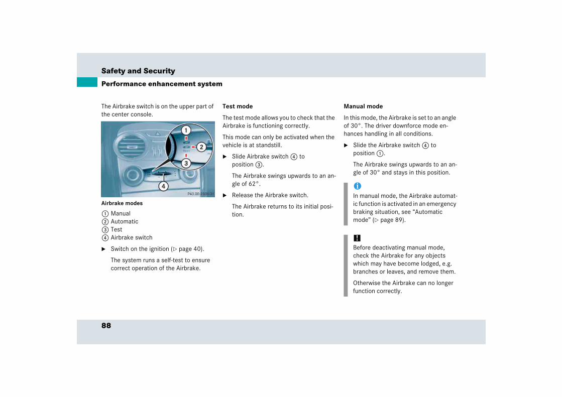
88
Safety and Security
Performance enhancement system
The Airbrake switch is on the upper part of the center console.
Airbrake modes
1 Manual 2 Automatic 3 Test 4 Airbrake switch
� Switch on the ignition (� page 40).
The system runs a self-test to ensure correct operation of the Airbrake.
Test mode
The test mode allows you to check that the Airbrake is functioning correctly.
This mode can only be activated when the vehicle is at standstill.
� Slide Airbrake switch 4 to position 3.
The Airbrake swings upwards to an an-gle of 62°.
� Release the Airbrake switch.
The Airbrake returns to its initial posi-tion.
Manual mode
In this mode, the Airbrake is set to an angle of 30°. The driver downforce mode en-hances handling in all conditions.
� Slide the Airbrake switch 4 to position 1.
The Airbrake swings upwards to an an-gle of 30° and stays in this position.
iIn manual mode, the Airbrake automat-ic function is activated in an emergency braking situation, see “Automatic mode” (� page 89).
!Before deactivating manual mode, check the Airbrake for any objects which may have become lodged, e.g. branches or leaves, and remove them.
Otherwise the Airbrake can no longer function correctly.
89
Safety and Security
Performance enhancement system
Automatic mode
This mode should be used for normal driv-ing conditions.
� Slide the Airbrake switch 4 to position 2.
With the ignition on the Airbrake swings upwards to an angle of 5° and then returns to its initial position.
When the vehicle exceeds a speed of 60 mph (95 km/h), the Airbrake swings up to an angle of 10°.
Rapid braking
If you need to brake in an emergency from a speed of more than 60 mph (95 km/h), the Airbrake automatically swings upwards to an angle of 62°.
This allows you to achieve the best possi-ble braking performance in an emergency.
Warning! G
Hard braking activates the Airbrake which may block the view through the interior rear view mirror. In this case, monitor the traffic behind you through the exterior rear view mirrors.

90
Safety and Security
Anti-theft systems
Immobilizer
The immobilizer prevents unauthorized persons from starting your vehicle.
Activating
Removing the SmartKey from the starter switch activates the immobilizer.
Deactivating
Inserting the SmartKey in the starter switch deactivates the immobilizer.
Anti-theft alarm system
Once the alarm system has been armed, a visual and audible alarm is triggered when someone opens
� a door
� the trunk lid
� the hood
� a storage compartment in the rear
� the storage compartment under the armrest
is opened.
The alarm system will also be triggered when
� someone attempts to raise the vehicle
� someone opens a door from the inside if the vehicle was locked from the out-side with the SmartKey
� someone opens the trunk lid with the emergency release button
iIn case the engine cannot be started (yet the vehicle’s battery is charged), the system is not operational. Contact an authorized Mercedes-Benz Center or call 1-800-FOR-MERCedes (in the USA), or 1-888-881-6611 (in Canada).
iThe alarm will stay on, even if the acti-vating element (a door, for example) is immediately closed.
If the alarm stays on for more than 30 seconds, a call to the Response Center is initiated automatically by the Tele Aid system (� page 215) provided Tele Aid service was subscribed to and properly activated, and that necessary cellular service and GPS coverage are available.
91
Safety and Security
Anti-theft systems
Arming the alarm system
� Lock the vehicle with the SmartKey.
The turn signal lamps flash three times to indicate that the alarm system is activated. The indicator lamp in the central locking switch (� page 104) be-gins to flash after arming the alarm system.
Disarming the alarm system
� Unlock your vehicle with the SmartKey.
The turn signal lamps flash once to indicate that the alarm system is deactivated.
Canceling the alarm
To cancel the alarm:
� Press the Œ or ‹ button on the SmartKey.
or
� Insert the SmartKey in the starter switch.
Tow-away alarm
Once the tow-away alarm is armed, a visual and audible alarm will be triggered when someone attempts to raise the vehicle.
iIf the turn signal lamps do not flash three times, one of the following elements may not be properly closed:
� a door
� the trunk
� the hood
Close the respective element and lock the vehicle again.
iThe alarm system will rearm automati-cally after approximately 40 seconds if neither a door nor the trunk lid was opened.
iThe tow-away protection alarm is triggered, for example, if the vehicle is lifted on one side.
If the alarm stays on for more than 30 seconds, a call to the Response Center is initiated automatically by the Tele Aid system (� page 215) provided Tele Aid service was subscribed to and properly activated, and that necessary cellular service and GPS coverage are available.
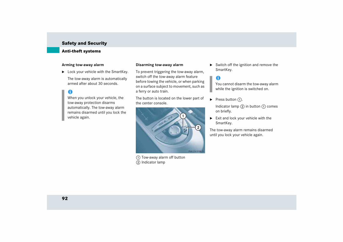
92
Safety and Security
Anti-theft systems
Arming tow-away alarm
� Lock your vehicle with the SmartKey.
The tow-away alarm is automatically armed after about 30 seconds.
Disarming tow-away alarm
To prevent triggering the tow-away alarm, switch off the tow-away alarm feature before towing the vehicle, or when parking on a surface subject to movement, such as a ferry or auto train.
The button is located on the lower part of the center console.
1 Tow-away alarm off button2 Indicator lamp
� Switch off the ignition and remove the SmartKey.
� Press button 1.
Indicator lamp 2 in button 1 comes on briefly.
� Exit and lock your vehicle with the SmartKey.
The tow-away alarm remains disarmed until you lock your vehicle again.
iWhen you unlock your vehicle, the tow-away protection disarms automatically. The tow-away alarm remains disarmed until you lock the vehicle again.
iYou cannot disarm the tow-away alarm while the ignition is switched on.
93
Safety and Security
Anti-theft systems
Canceling the alarm
To cancel the alarm:
� Press the Œ or ‹ button on the SmartKey.
or
� Insert the SmartKey in the starter switch.
Controls in detail
Locking and unlocking
Lighting
Instrument cluster
Control system
Audio system
Automatic transmission
Good visibility
Automatic climate control
Power windows
Driving systems
Useful features

96
Controls in detail
In the “Controls in detail” section you will find detailed information on how to oper-ate the equipment installed on your vehi-cle. If you are already familiar with the basic functions of your vehicle, this section will be of particular interest to you.
To quickly familiarize yourself with the ba-sic functions of the vehicle, refer to the “Getting started” section of this manual. The corresponding page numbers are giv-en at the beginning of each segment.
Locking and unlocking
SmartKey
Your vehicle comes supplied with two SmartKeys, each with remote control and a removable mechanical key.
The SmartKey provides an extended oper-ating range. To prevent theft, however, it is advisable to only unlock the vehicle when you are in close proximity to it.
The SmartKey centrally locks and unlocks:
� the doors
� the trunk
� the fuel filler flap
Key with remote control
1 ‹ Lock button2 Š Unlock button for the trunk lid3 Mechanical key locking tab4 Œ Unlock button5 Battery check lamp6  Panic button
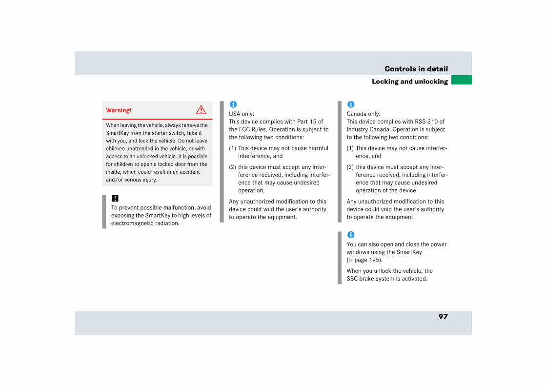
97
Controls in detail
Locking and unlocking
Warning! G
When leaving the vehicle, always remove the SmartKey from the starter switch, take it with you, and lock the vehicle. Do not leave children unattended in the vehicle, or with access to an unlocked vehicle. It is possible for children to open a locked door from the inside, which could result in an accident and/or serious injury.
!To prevent possible malfunction, avoid exposing the SmartKey to high levels of electromagnetic radiation.
iUSA only: This device complies with Part 15 of the FCC Rules. Operation is subject to the following two conditions:
(1) This device may not cause harmful interference, and
(2) this device must accept any inter-ference received, including interfer-ence that may cause undesired operation.
Any unauthorized modification to this device could void the user’s authority to operate the equipment.
iCanada only:This device complies with RSS-210 of Industry Canada. Operation is subject to the following two conditions:
(1) This device may not cause interfer-ence, and
(2) this device must accept any inter-ference received, including interfer-ence that may cause undesired operation of the device.
Any unauthorized modification to this device could void the user’s authority to operate the equipment.
iYou can also open and close the power windows using the SmartKey (� page 195).
When you unlock the vehicle, the SBC brake system is activated.
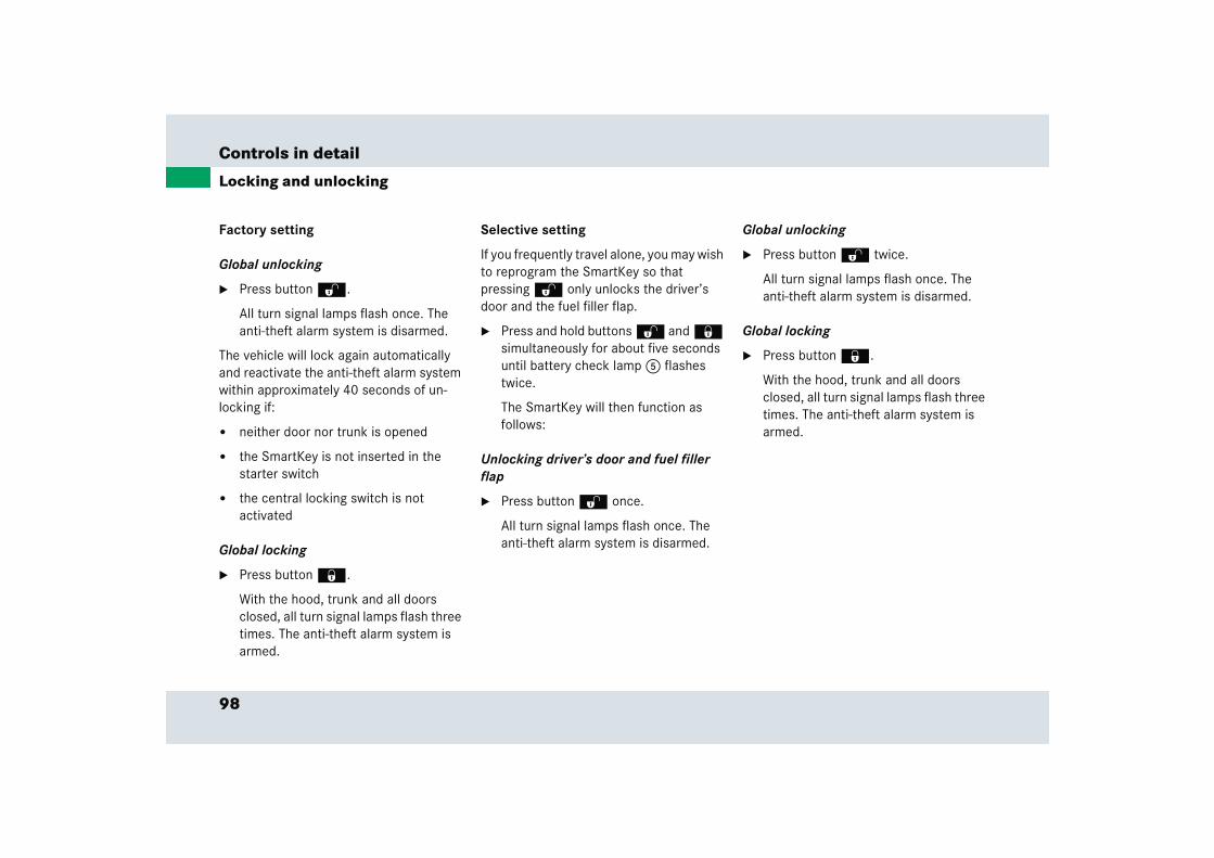
98
Controls in detail
Locking and unlocking
Factory setting
Global unlocking
� Press button Œ.
All turn signal lamps flash once. The anti-theft alarm system is disarmed.
The vehicle will lock again automatically and reactivate the anti-theft alarm system within approximately 40 seconds of un-locking if:
� neither door nor trunk is opened
� the SmartKey is not inserted in the starter switch
� the central locking switch is not activated
Global locking
� Press button ‹.
With the hood, trunk and all doors closed, all turn signal lamps flash three times. The anti-theft alarm system is armed.
Selective setting
If you frequently travel alone, you may wish to reprogram the SmartKey so that pressing Œ only unlocks the driver’s door and the fuel filler flap.
� Press and hold buttons Œ and ‹ simultaneously for about five seconds until battery check lamp 5 flashes twice.
The SmartKey will then function as follows:
Unlocking driver’s door and fuel filler flap
� Press button Œ once.
All turn signal lamps flash once. The anti-theft alarm system is disarmed.
Global unlocking
� Press button Œ twice.
All turn signal lamps flash once. The anti-theft alarm system is disarmed.
Global locking
� Press button ‹.
With the hood, trunk and all doors closed, all turn signal lamps flash three times. The anti-theft alarm system is armed.
99
Controls in detail
Locking and unlocking
Restoring to factory setting
� Press and hold buttons Œ and ‹ simultaneously for about six seconds until battery check lamp 5 (� page 96) flashes twice.
Checking the batteries
� Press button ‹ or Œ.
Battery check lamp 5 (� page 96) comes on briefly to indicate that the SmartKey batteries are in order.
Unlocking and opening the trunk lid
You can unlock the trunk separately.
A minimum height clearance of 5.5 ft (1.65 m) is required to open the trunk lid.
� Press and hold button Š until the trunk unlocks and opens slightly.
!If you can no longer lock or unlock the vehicle with the SmartKey, then either the batteries in the SmartKey are dis-charged, the SmartKey is malfunction-ing or the vehicle battery is drained.
� Check the batteries in the SmartKey (� page 99) and replace them if necessary (� page 344).
� Use the mechanical key to unlock the vehicle (� page 342).
� Have the vehicle battery and the battery connections checked. Con-tact an authorized Mercedes-Benz Center.
If the SmartKey is malfunctioning, contact an authorized Mercedes-Benz Center.
!If battery check lamp 5 does not come on briefly during check, then the SmartKey batteries are discharged.
� Replace the batteries (� page 344).
You can obtain the required batteries at any authorized Mercedes-Benz Center.
iIf the batteries are checked within signal range of the vehicle, pressing the ‹ or Œ button will lock or unlock the vehicle accordingly.
iIf the vehicle was previously centrally locked, the trunk lid will lock automati-cally when closed. The turn signals will flash three times to confirm locking.

100
Controls in detail
Locking and unlocking
Loss of SmartKey or mechanical key
If you lose a SmartKey or mechanical key, you should do the following:
� Have the SmartKey deactivated by an authorized Mercedes-Benz Center.
� Report the loss of the SmartKey or the mechanical key immediately to your car insurance company.
� If necessary, have the trunk lock replaced.
Your authorized Mercedes-Benz Center will be glad to supply you with a replace-ment.
Opening the doors
Opening from the outside
For information on opening the doors from the outside, see “Getting started” (� page 38).
Opening from the inside
You can open a locked door from the in-side. Open the door only if the vehicle is stationary and when conditions are safe to do so.
1 Inside door handle
� Pull on door handle 1.
The door swings outwards and up-wards automatically.
!Ensure sufficient side- and overhead clearance prior to opening the doors, see “Main dimensions” (� page 373).
iIf the vehicle has previously been locked from the outside with the SmartKey, opening a door from the inside will trigger the anti-theft alarm system.
To cancel the alarm, do one of the following:
� Press button Œ or ‹ on the SmartKey.
� Insert the SmartKey in the starter switch.

101
Controls in detail
Locking and unlocking
Opening the trunk
Opening the trunk from the outside
A minimum height clearance of 5.5 ft (1.65 m) is required to open the trunk lid.
The handle is located above the rear license plate recess.
1 Trunk lock2 Handle
The vehicle must be unlocked.
� Pull on handle 2 and lift the trunk lid.
The trunk can also be opened using button Š on the SmartKey or from its inside in an emergency, see “Trunk lid emergency release” (� page 102).
Opening the trunk from the inside
You can open the trunk from the inside if the vehicle is stationary.
A minimum height clearance of 5.5 ft (1.65 m) is required to open the trunk lid.
The switch is located on the lower part of the center console.
1 Remote trunk lid release switch
� Press remote trunk lid release switch 1 until the trunk lid unlocks.
� Lift the trunk lid.
The trunk can also be opened using button Š on the SmartKey or from its inside in an emergency, see “Trunk lid emergency release” (� page 102).
!Always make sure that there is suffi-cient overhead clearance.
!Always make sure that there is suffi-cient overhead clearance.
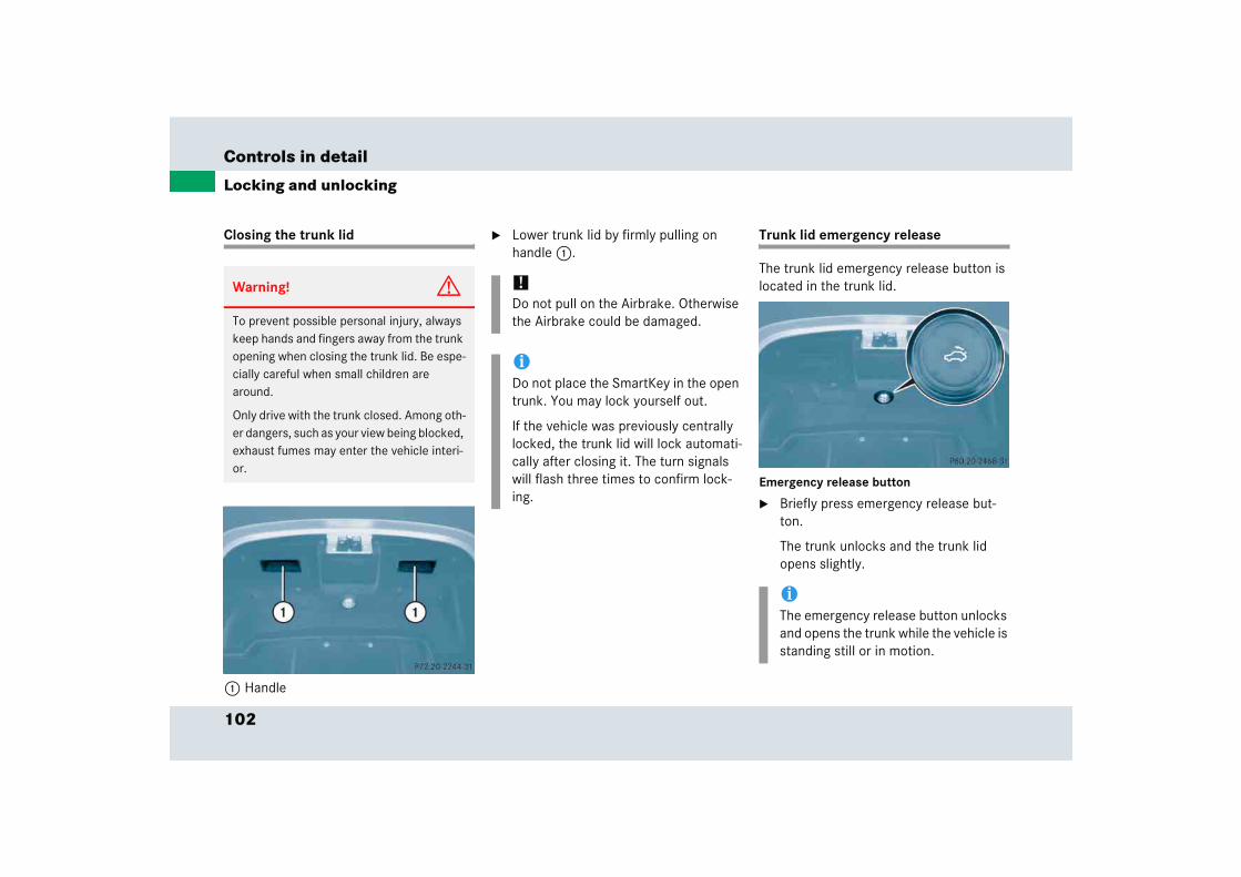
102
Controls in detail
Locking and unlocking
Closing the trunk lid
1 Handle
� Lower trunk lid by firmly pulling on handle 1.
Trunk lid emergency release
The trunk lid emergency release button is located in the trunk lid.
Emergency release button
� Briefly press emergency release but-ton.
The trunk unlocks and the trunk lid opens slightly.
Warning! G
To prevent possible personal injury, always keep hands and fingers away from the trunk opening when closing the trunk lid. Be espe-cially careful when small children are around.
Only drive with the trunk closed. Among oth-er dangers, such as your view being blocked, exhaust fumes may enter the vehicle interi-or.
!Do not pull on the Airbrake. Otherwise the Airbrake could be damaged.
iDo not place the SmartKey in the open trunk. You may lock yourself out.
If the vehicle was previously centrally locked, the trunk lid will lock automati-cally after closing it. The turn signals will flash three times to confirm lock-ing.
iThe emergency release button unlocks and opens the trunk while the vehicle is standing still or in motion.
103
Controls in detail
Locking and unlocking
Illumination of the emergency release button:
� The button will flash for 30 minutes after opening the trunk.
� The button will flash for 60 minutes after closing the trunk.
Automatic locking
The doors and the trunk lid lock automati-cally when the vehicle is set into motion.
You can open a locked door from the in-side. Open door only when conditions are safe to do so.
You can deactivate the automatic locking using the control system (� page 135).
Locking and unlocking from the inside
You can lock or unlock the vehicle from in-side using the central locking switches. This can be useful, for example, if you want to unlock the passenger door from the in-side or want to lock the vehicle before starting to drive.
The central locking switch does not lock or unlock the fuel filler flap.
iThe emergency release button does not open the trunk lid if the vehicle battery is discharged or disconnected.
If the vehicle has previously been locked from the outside with the SmartKey, opening the trunk from the inside using the emergency release button will trigger the anti-theft alarm system.
To cancel the alarm, do one of the following:
� Press button Œ or ‹ on the SmartKey.
� Insert the SmartKey in the starter switch.
iThe doors unlock automatically after an accident if the force of the impact ex-ceeds a preset threshold.
The vehicle locks automatically when the ignition is switched on and the wheels are turning at vehicle speeds of approximately 9 mph (15 km/h) or more. You could therefore lock yourself out when the vehicle
� is pushed
� is on a test stand
Warning! G
When leaving the vehicle, always remove the SmartKey from the starter switch, take it with you, and lock the vehicle. Do not leave children unattended in the vehicle, or with access to an unlocked vehicle. Unsuper-vised use of vehicle equipment may cause an accident and/or serious personal injury.
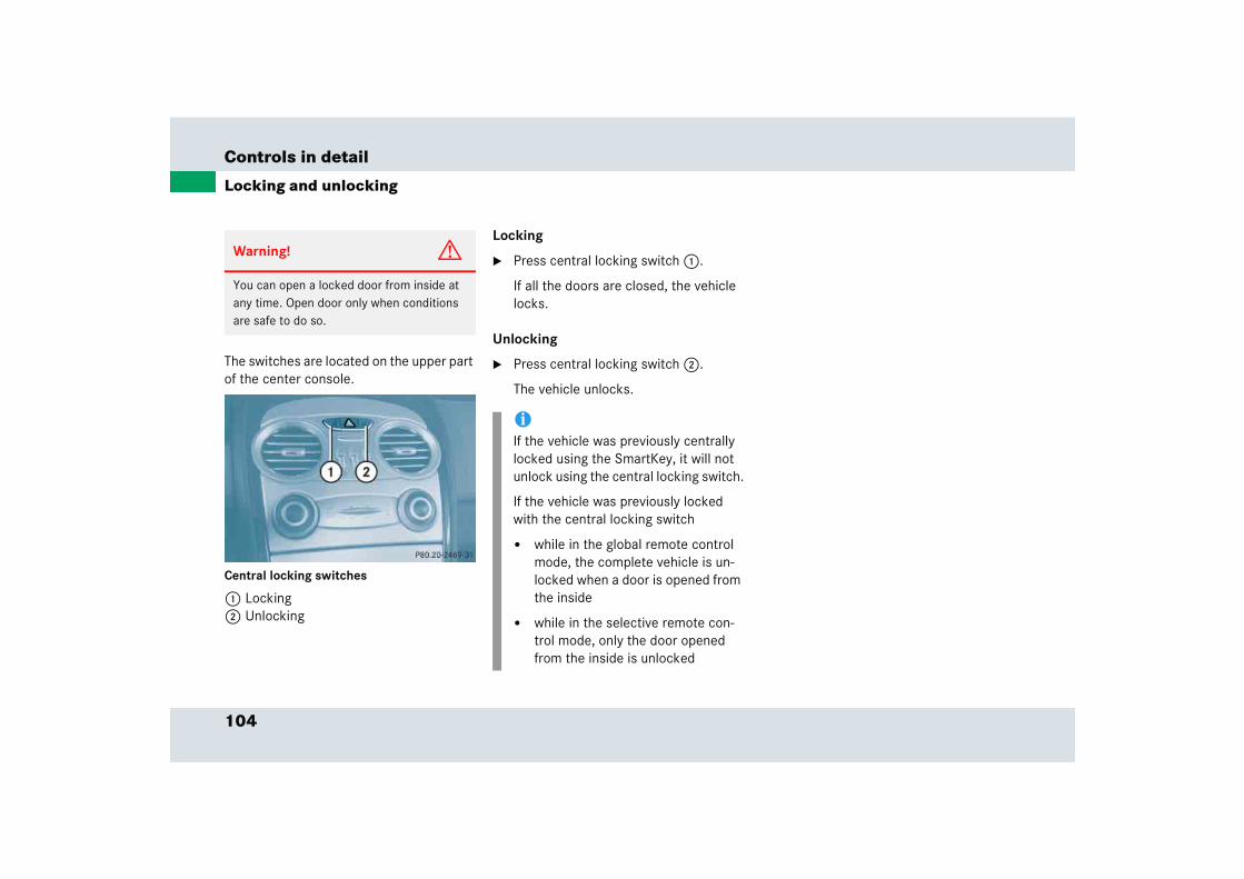
104
Controls in detail
Locking and unlocking
The switches are located on the upper part of the center console.
Central locking switches
1 Locking2 Unlocking
Locking
� Press central locking switch 1.
If all the doors are closed, the vehicle locks.
Unlocking
� Press central locking switch 2.
The vehicle unlocks.
Warning! G
You can open a locked door from inside at any time. Open door only when conditions are safe to do so.
iIf the vehicle was previously centrally locked using the SmartKey, it will not unlock using the central locking switch.
If the vehicle was previously locked with the central locking switch
� while in the global remote control mode, the complete vehicle is un-locked when a door is opened from the inside
� while in the selective remote con-trol mode, only the door opened from the inside is unlocked
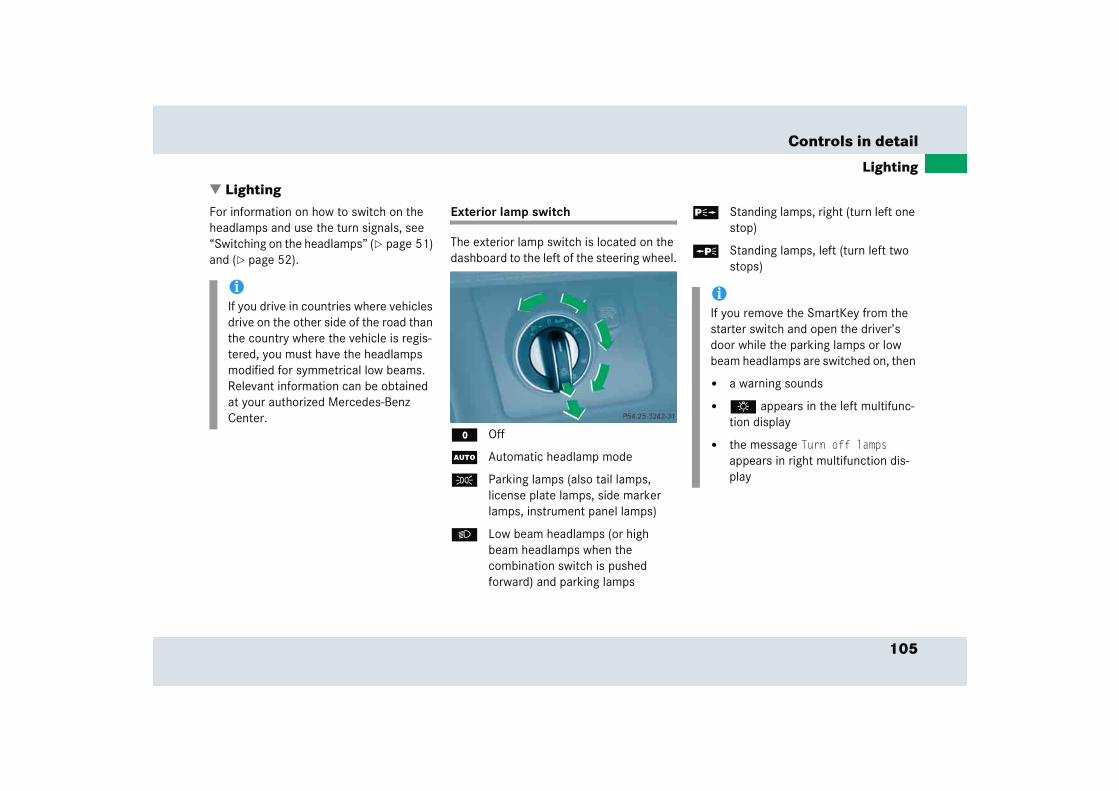
105
Controls in detail
Lighting
� LightingFor information on how to switch on the headlamps and use the turn signals, see “Switching on the headlamps” (� page 51) and (� page 52).
Exterior lamp switch
The exterior lamp switch is located on the dashboard to the left of the steering wheel.
M Off
U Automatic headlamp mode
C Parking lamps (also tail lamps, license plate lamps, side marker lamps, instrument panel lamps)
B Low beam headlamps (or high beam headlamps when the combination switch is pushed forward) and parking lamps
ˆ Standing lamps, right (turn left one stop)
‚ Standing lamps, left (turn left two stops)
iIf you drive in countries where vehicles drive on the other side of the road than the country where the vehicle is regis-tered, you must have the headlamps modified for symmetrical low beams. Relevant information can be obtained at your authorized Mercedes-Benz Center.
iIf you remove the SmartKey from the starter switch and open the driver’s door while the parking lamps or low beam headlamps are switched on, then
� a warning sounds
� $ appears in the left multifunc-tion display
� the message Turn off lamps appears in right multifunction dis-play
106
Controls in detail
Lighting
Manual headlamp mode
The low beam headlamps and the parking lamps can be switched on and off with the exterior lamp switch.
Automatic headlamp mode
The following lamps switch on and off automatically depending on the brightness of the ambient light:
� Low beam headlamps
� Tail and parking lamps
� License plate lamps
� Side marker lamps
� Turn the exterior lamp switch to position U.
With the SmartKey in starter switch position 1, only the parking lamps will switch on and off automatically.
When the engine is running, the low beam headlamps, the tail and parking lamps, the license plate lamps, and the side marker lamps will switch on and off automatically.
Warning! G
If the exterior lamp switch is set to U,
� the headlamps may switch off unexpect-edly when the system senses bright ambient light, for example light from oncoming traffic.
� the headlamps will not be automatically switched on under foggy conditions.
To minimize risk to you and to others, activate headlamps by turning exterior lamp switch to B when driving or when traffic and/or ambient lighting conditions require you to do so.
In low ambient lighting conditions, only switch from position U to B with the vehicle at a standstill. Switching from U to B will briefly switch off the headlamps. Doing so while driving in low ambient lighting conditions may result in an accident.
The automatic headlamp feature is only an aid to the driver. The driver is responsible for the operation of the vehicle's lights at all times.
iFog lamps cannot be switched on with the exterior lamp switch in position U. For switching on the fog lamps, turn the exterior lamp switch to position B first.
107
Controls in detail
Lighting
Daytime running lamp mode
� Turn the exterior lamp switch to position M or U.
When the engine is running, the low beam headlamps are switched on.
In low ambient light conditions, the following lamps will switch on additionally:
� Tail and parking lamps
� License plate lamps
� Side marker lamps
For nighttime driving you should turn the exterior lamp switch to position B to permit activation of the high beam head-lamps.
Canada only:
The daytime running lamp mode is manda-tory and therefore in a constant mode.
When the engine is running, and you shift from a driving position to position N or P, the low beam headlamps will switch off with a three-minute delay.
When the engine is running, and you
� turn the exterior lamp switch to position C, the parking lamps switch on additionally.
� turn the exterior lamp switch to position B, the manual headlamp mode has priority over the daytime running lamp mode.
The corresponding exterior lamps switch on (� page 105).
USA only:
By default, the daytime running lamp mode is deactivated. Activate the daytime running lamp mode using the control system, see “Setting daytime running lamp mode (USA only)” (� page 131).
When the engine is running, and you turn the exterior lamp switch to position C or B, the manual headlamp mode has priority over the daytime running lamp mode.
The corresponding exterior lamps switch on (� page 105).
iWith the daytime running lamp mode activated and the exterior lamp switch in position M, the high beam head-lamps cannot be switched on.
The high beam flasher is available at all times.

108
Controls in detail
Lighting
Locator lighting and night security illumination
The locator lighting and the night security illumination are described in the “Control system” section, see “Setting locator light-ing” (� page 132) and “Setting night secu-rity illumination” (� page 132).
Fog lamps
Front fog lamps
� Switch on the low beam headlamps (� page 105).
� Pull out the exterior lamp switch to first stop.
The front fog lamps switch on.
The green indicator lamp ‡ in the exterior lamp switch comes on.
� Push in the exterior lamp switch.
The front fog lamps switch off.
The green indicator lamp ‡ in the exterior lamp switch goes out.
Warning! G
In low ambient lighting or foggy conditions, only switch from position U to B with the vehicle at a standstill. Switching from U to B will briefly switch off the headlamps. Doing so while driving in low ambient lighting conditions may result in an accident.
iFog lamps will operate with the parking lamps and/or the low beam headlamps on. Fog lamps should only be used in conjunction with low beam headlamps. Consult your State or Province Motor Vehicle Regulations regarding permis-sible lamp operation.
iFog lamps cannot be switched on with the exterior lamp switch in position U. For switching on the fog lamps, turn the exterior lamp switch to position B first.
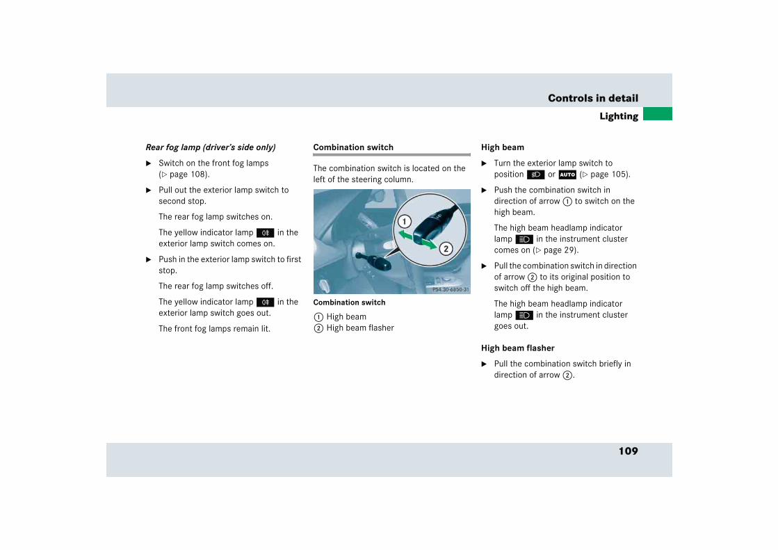
109
Controls in detail
Lighting
Rear fog lamp (driver’s side only)
� Switch on the front fog lamps (� page 108).
� Pull out the exterior lamp switch to second stop.
The rear fog lamp switches on.
The yellow indicator lamp † in the exterior lamp switch comes on.
� Push in the exterior lamp switch to first stop.
The rear fog lamp switches off.
The yellow indicator lamp † in the exterior lamp switch goes out.
The front fog lamps remain lit.
Combination switch
The combination switch is located on the left of the steering column.
Combination switch
1 High beam2 High beam flasher
High beam
� Turn the exterior lamp switch to position B or U (� page 105).
� Push the combination switch in direction of arrow 1 to switch on the high beam.
The high beam headlamp indicator lamp A in the instrument cluster comes on (� page 29).
� Pull the combination switch in direction of arrow 2 to its original position to switch off the high beam.
The high beam headlamp indicator lamp A in the instrument cluster goes out.
High beam flasher
� Pull the combination switch briefly in direction of arrow 2.
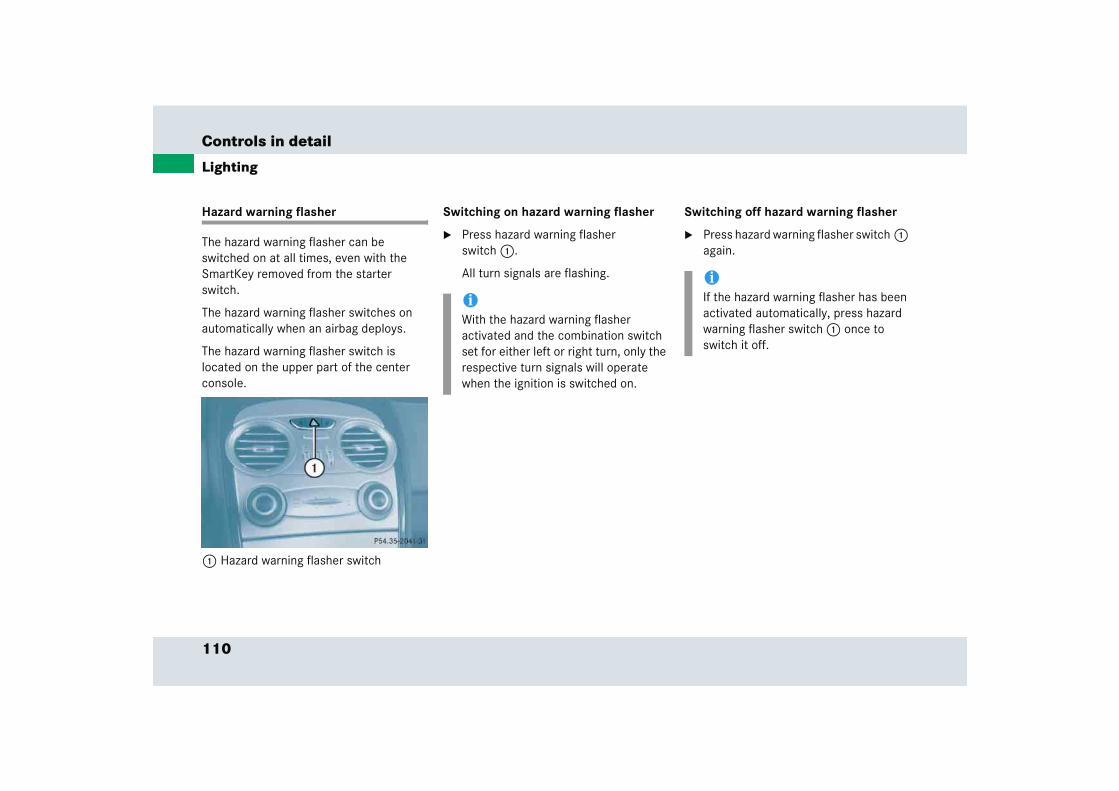
110
Controls in detail
Lighting
Hazard warning flasher
The hazard warning flasher can be switched on at all times, even with the SmartKey removed from the starter switch.
The hazard warning flasher switches on automatically when an airbag deploys.
The hazard warning flasher switch is located on the upper part of the center console.
1 Hazard warning flasher switch
Switching on hazard warning flasher
� Press hazard warning flasher switch 1.
All turn signals are flashing.
Switching off hazard warning flasher
� Press hazard warning flasher switch 1 again.
iWith the hazard warning flasher activated and the combination switch set for either left or right turn, only the respective turn signals will operate when the ignition is switched on.
iIf the hazard warning flasher has been activated automatically, press hazard warning flasher switch 1 once to switch it off.
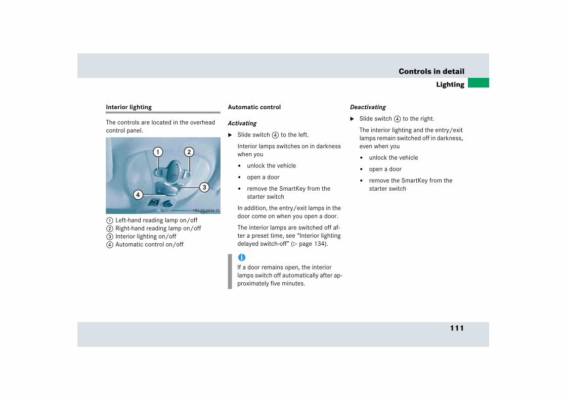
111
Controls in detail
Lighting
Interior lighting
The controls are located in the overhead control panel.
1 Left-hand reading lamp on/off2 Right-hand reading lamp on/off3 Interior lighting on/off4 Automatic control on/off
Automatic control
Activating
� Slide switch 4 to the left.
Interior lamps switches on in darkness when you
� unlock the vehicle
� open a door
� remove the SmartKey from the starter switch
In addition, the entry/exit lamps in the door come on when you open a door.
The interior lamps are switched off af-ter a preset time, see “Interior lighting delayed switch-off” (� page 134).
Deactivating
� Slide switch 4 to the right.
The interior lighting and the entry/exit lamps remain switched off in darkness, even when you
� unlock the vehicle
� open a door
� remove the SmartKey from the starter switch
iIf a door remains open, the interior lamps switch off automatically after ap-proximately five minutes.
112
Controls in detail
Lighting
Manual control
Switching lamps on
� Press switch 3.
The interior lighting switches on.
Switching lamps off
� Press switch 3 again.
The interior lighting switches off.
Trunk lamp
The trunk lamp switches on if the trunk lid is opened.
If you leave the trunk open for an extended period of time, the trunk lamp will switch off automatically after approximately ten minutes.
Courtesy lighting
For better orientation in the dark, courtesy lamps will illuminate the interior of your vehicle.
When you open a door:
� the driver’s and passenger’s footwells
If the SmartKey is in starter switch position 1:
� the center console
!Make sure the interior lighting is switched off when leaving the vehicle. i
The setting selected for the interior lighting is used for the trunk lighting as well. i
The center console is lit from the interior rear view mirror.
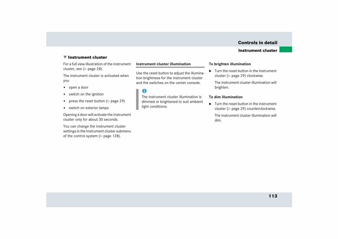
113
Controls in detail
Instrument cluster
� Instrument clusterFor a full view illustration of the instrument cluster, see (� page 28).
The instrument cluster is activated when you
� open a door
� switch on the ignition
� press the reset button (� page 29)
� switch on exterior lamps
Opening a door will activate the instrument cluster only for about 30 seconds.
You can change the instrument cluster settings in the Instrument cluster submenu of the control system (� page 128).
Instrument cluster illumination
Use the reset button to adjust the illumina-tion brightness for the instrument cluster and the switches on the center console.
To brighten illumination
� Turn the reset button in the instrument cluster (� page 29) clockwise.
The instrument cluster illumination will brighten.
To dim illumination
� Turn the reset button in the instrument cluster (� page 29) counterclockwise.
The instrument cluster illumination will dim.
iThe instrument cluster illumination is dimmed or brightened to suit ambient light conditions.
114
Controls in detail
Instrument cluster
Coolant temperature gauge During severe operating conditions, e.g. stop-and-go traffic, the coolant tempera-ture may rise close to 248°F (120°C).
The engine should not be operated with the coolant temperature above 248°F (120°C). Doing so may cause serious en-gine damage which is not covered by the Mercedes-Benz Limited Warranty.
Warning G
� Driving when your engine is badly over-heated can cause some fluids which may have leaked into the engine com-partment to catch fire. You could be se-riously burned.
� Steam from an overheated engine can cause serious burns an can occur just by opening the hood. Stay away from the engine if you see or hear steam coming from it.
Turn off the engine, get out of the vehicle and do not stand near the vehicle until the engine has cooled down.
!Excessive coolant temperature triggers the coolant temperature warning lamp (� page 300) and a warning in the multifunction display (� page 320).
115
Controls in detail
Instrument cluster
Resetting the trip odometer
� Make sure you are viewing the trip odometer and main odometer in the right multifunction display (� page 117).
� If it is not displayed, press button è or ÿ on the multifunction steering wheel until the trip odometer appears in the right multifunction display.
� Press and hold reset button 4 (� page 29) until the trip odometer is reset.
Tachometer
The red marking on the tachometer (� page 29) denotes excessive engine speed.
To help protect the engine, the fuel supply is interrupted if the engine is operated within the red marking.
Outside temperature indicator
The outside temperature is displayed in the right multifunction display (� page 29). For information on how to se-lect the unit of the displayed temperature, i.e. degrees Celsius (°C) or degrees Fahr-enheit (°F), see “Selecting temperature display mode” (� page 129).
!Avoid driving at excessive engine speeds, as it may result in serious engine damage that is not covered by the Mercedes-Benz Limited Warranty.
Warning! G
The outside temperature indicator is not de-signed to serve as an ice-warning device and is therefore unsuitable for that purpose.
Indicated temperatures just above the freez-ing point do not guarantee that the road sur-face is free of ice. The road may still be icy, especially in wooded areas or on bridges.
116
Controls in detail
Instrument cluster
The temperature sensor is located in the front bumper area. Due to its location, the sensor can be affected by road or engine heat during idling or slow driving. There-fore, the accuracy of the displayed temper-ature can only be verified by comparison to a thermometer placed next the sensor, not by comparison to external displays, e.g. bank signs, etc.
When moving the vehicle into colder ambi-ent temperatures (e.g. when leaving your garage), you will notice a delay before the lower temperature is displayed.
A delay also occurs when ambient temper-atures rise. This prevents inaccurate tem-perature indications caused by heat radiated from the engine during idling or slow driving.
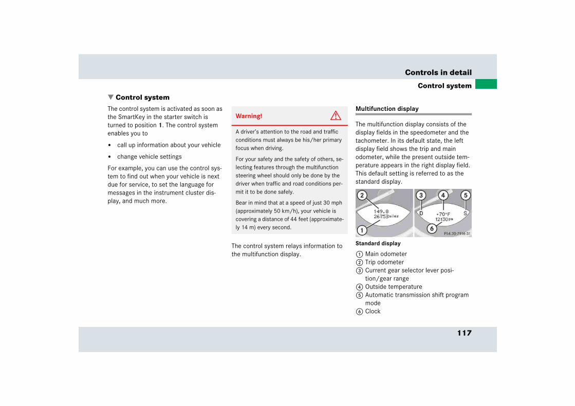
117
Controls in detail
Control system
� Control systemThe control system is activated as soon as the SmartKey in the starter switch is turned to position 1. The control system enables you to
� call up information about your vehicle
� change vehicle settings
For example, you can use the control sys-tem to find out when your vehicle is next due for service, to set the language for messages in the instrument cluster dis-play, and much more.
The control system relays information to the multifunction display.
Multifunction display
The multifunction display consists of the display fields in the speedometer and the tachometer. In its default state, the left display field shows the trip and main odometer, while the present outside tem-perature appears in the right display field. This default setting is referred to as the standard display.
Standard display
1 Main odometer2 Trip odometer3 Current gear selector lever posi-
tion/gear range4 Outside temperature5 Automatic transmission shift program
mode6 Clock
Warning! G
A driver’s attention to the road and traffic conditions must always be his/her primary focus when driving.
For your safety and the safety of others, se-lecting features through the multifunction steering wheel should only be done by the driver when traffic and road conditions per-mit it to be done safely.
Bear in mind that at a speed of just 30 mph (approximately 50 km/h), your vehicle is covering a distance of 44 feet (approximate-ly 14 m) every second.
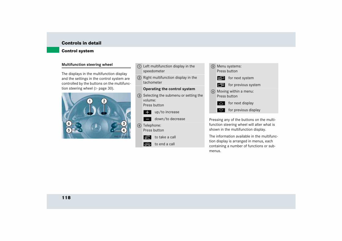
118
Controls in detail
Control system
Multifunction steering wheel
The displays in the multifunction display and the settings in the control system are controlled by the buttons on the multifunc-tion steering wheel (� page 30).
Pressing any of the buttons on the multi-function steering wheel will alter what is shown in the multifunction display.
The information available in the multifunc-tion display is arranged in menus, each containing a number of functions or sub-menus.
1 Left multifunction display in the speedometer
2 Right multifunction display in the tachometer
Operating the control system
3 Selecting the submenu or setting the volume:Press button
æ up/to increase
ç down/to decrease
4 Telephone:Press button
í to take a call
ì to end a call
5 Menu systems:Press button
è for next system
ÿ for previous system
6 Moving within a menu:Press button
j for next display
k for previous display

119
Controls in detail
Control system
The individual functions are then found within the relevant menu (radio or CD op-erations under AUDIO, for example). These functions serve to call up relevant informa-tion or to customize the settings for your vehicle.
It is helpful to think of the menus, and the functions within each menu, as being arranged in a circular pattern.
� If you press button è or ÿ repeatedly, you will pass through each menu one after the other.
� If you press button k or j repeatedly, you will pass through each function display, one after the other, in the current menu.
In the Settings menu, instead of functions you will find a number of submenus for calling up and changing settings. For instructions on using these submenus, see “Settings menu” (� page 125).
The number of menus available in the sys-tem depends on which optional equipment is installed in your vehicle.
The menus are described on the following pages.
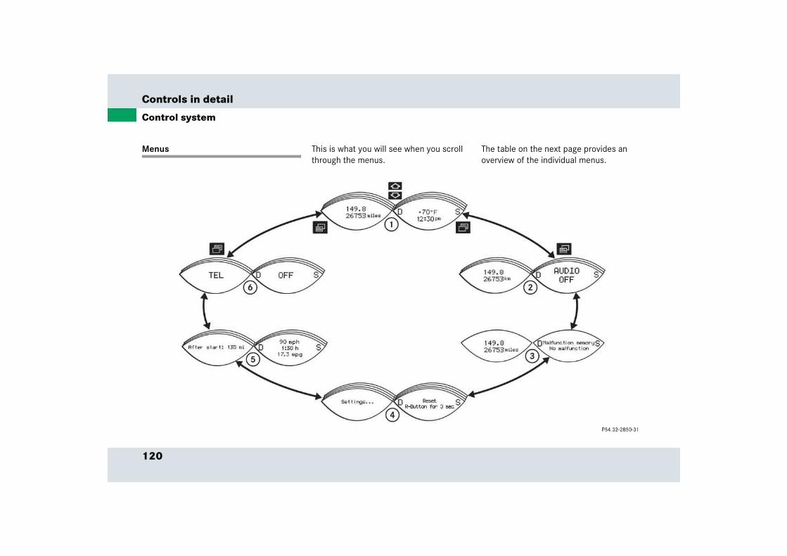
120
Controls in detail
Control system
Menus This is what you will see when you scroll through the menus.
The table on the next page provides an overview of the individual menus.

121
Controls in detail
Control system
Menus, submenus and functions
Menu 1 Menu 2 Menu 3 Menu 4 Menu 5 Menu 6
Standard display AUDIO Vehicle status message memory
Settings Trip computer Telephone
(� page 122) (� page 122) (� page 124) (� page 125) (� page 136) (� page 138)
Com
man
ds/s
ubm
enus
Digital speedometer Select radio station Call up vehicle mal-function, warning and system status messages stored in memory
Reset to factory set-tings
Fuel consumption statistics after start
Load phone book
Call up maintenance service display
Operate the CD player
Instrument cluster submenu
Fuel consumption statistics since the last reset
Search for name in phone book
Check tire inflation pressure
Lighting submenu Call up range
Vehicle submenu
122
Controls in detail
Control system
Standard display menu
You can select the functions in the stan-dard display menu with button k or j .
The following functions are available:
Display digital speedometer
� Press button j once.
The current vehicle speed is shown in the multifunction display.
AUDIO menu
The functions in the AUDIO menu operate the audio equipment which you currently have turned on.
If no audio equipment is currently turned on, the message AUDIO OFF appears in the multifunction display.
The following functions are available:
iThe headings used in the menus table are designed to facilitate navigation within the system and are not neces-sarily identical to those shown in the control system displays.
The first function displayed in each menu will automatically show you which part of the system you are in.
Function Page
Call up digital speedometer 122
Call up maintenance service dis-play
286
Check tire inflation pressure 264
Function Page
Select radio station 123
Operate CD player 123
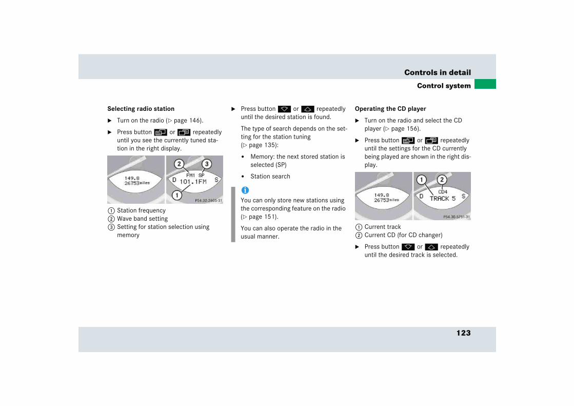
123
Controls in detail
Control system
Selecting radio station
� Turn on the radio (� page 146).
� Press button è or ÿ repeatedly until you see the currently tuned sta-tion in the right display.
1 Station frequency2 Wave band setting3 Setting for station selection using
memory
� Press button k or j repeatedly until the desired station is found.
The type of search depends on the set-ting for the station tuning (� page 135):
� Memory: the next stored station is selected (SP)
� Station search
Operating the CD player
� Turn on the radio and select the CD player (� page 156).
� Press button è or ÿ repeatedly until the settings for the CD currently being played are shown in the right dis-play.
1 Current track2 Current CD (for CD changer)
� Press button k or j repeatedly until the desired track is selected.
iYou can only store new stations using the corresponding feature on the radio (� page 151).
You can also operate the radio in the usual manner.
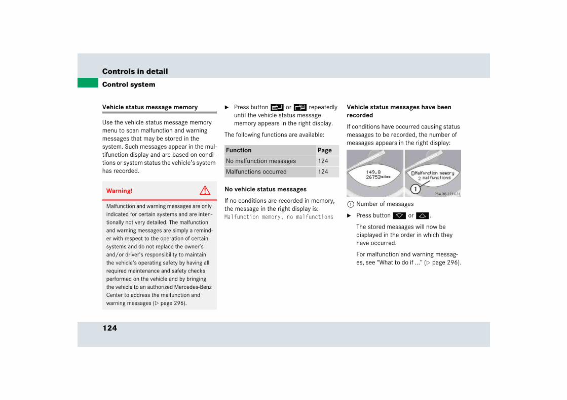
124
Controls in detail
Control system
Vehicle status message memory
Use the vehicle status message memory menu to scan malfunction and warning messages that may be stored in the system. Such messages appear in the mul-tifunction display and are based on condi-tions or system status the vehicle’s system has recorded.
� Press button è or ÿ repeatedly until the vehicle status message memory appears in the right display.
The following functions are available:
No vehicle status messages
If no conditions are recorded in memory, the message in the right display is: Malfunction memory, no malfunctions
Vehicle status messages have been recorded
If conditions have occurred causing status messages to be recorded, the number of messages appears in the right display:
1 Number of messages
� Press button k or j.
The stored messages will now be displayed in the order in which they have occurred.
For malfunction and warning messag-es, see “What to do if ...” (� page 296).
Warning! G
Malfunction and warning messages are only indicated for certain systems and are inten-tionally not very detailed. The malfunction and warning messages are simply a remind-er with respect to the operation of certain systems and do not replace the owner’s and/or driver’s responsibility to maintain the vehicle’s operating safety by having all required maintenance and safety checks performed on the vehicle and by bringing the vehicle to an authorized Mercedes-Benz Center to address the malfunction and warning messages (� page 296).
Function Page
No malfunction messages 124
Malfunctions occurred 124
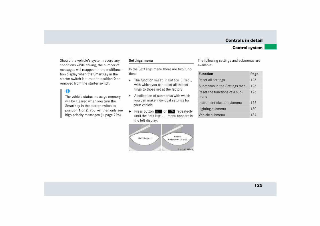
125
Controls in detail
Control system
Should the vehicle’s system record any conditions while driving, the number of messages will reappear in the multifunc-tion display when the SmartKey in the starter switch is turned to position 0 or removed from the starter switch.
Settings menu
In the Settings menu there are two func-tions:
� The function Reset R-Button 3 sec., with which you can reset all the set-tings to those set at the factory.
� A collection of submenus with which you can make individual settings for your vehicle.
� Press button è or ÿ repeatedly until the Settings... menu appears in the left display.
The following settings and submenus are available:
iThe vehicle status message memory will be cleared when you turn the SmartKey in the starter switch to position 1 or 2. You will then only see high-priority messages (� page 296).
Function Page
Reset all settings 126
Submenus in the Settings menu 126
Reset the functions of a sub-menu
126
Instrument cluster submenu 128
Lighting submenu 130
Vehicle submenu 134
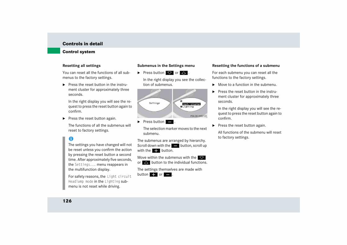
126
Controls in detail
Control system
Resetting all settings
You can reset all the functions of all sub-menus to the factory settings.
� Press the reset button in the instru-ment cluster for approximately three seconds.
In the right display you will see the re-quest to press the reset button again to confirm.
� Press the reset button again.
The functions of all the submenus will reset to factory settings.
Submenus in the Settings menu
� Press button k or j .
In the right display you see the collec-tion of submenus.
� Press button ç .
The selection marker moves to the next submenu.
The submenus are arranged by hierarchy. Scroll down with the ç button, scroll up with the æ button.
Move within the submenus with the k or j button to the individual functions.
The settings themselves are made with button æ or ç.
Resetting the functions of a submenu
For each submenu you can reset all the functions to the factory settings.
� Move to a function in the submenu.
� Press the reset button in the instru-ment cluster for approximately three seconds.
In the right display you will see the re-quest to press the reset button again to confirm.
� Press the reset button again.
All functions of the submenu will reset to factory settings.i
The settings you have changed will not be reset unless you confirm the action by pressing the reset button a second time. After approximately five seconds, the Settings... menu reappears in the multifunction display.
For safety reasons, the Light circuit Headlamp mode in the Lighting sub-menu is not reset while driving.

127
Controls in detail
Control system
The table below shows what settings can be changed within the various menus. De-tailed instructions on making individual settings can be found on the following pag-es.
Instrument cluster Lighting Vehicle
Set time (hours) Set daytime running lamp mode (USA only) Set station selection mode (radio)
Set time (minutes) Set locator lighting Set automatic locking
Select time display mode Exterior lamps delayed switch-off Tire inflation pressure display
Select temperature display mode Interior lighting delayed switch-off
Select speedometer display mode
Select language
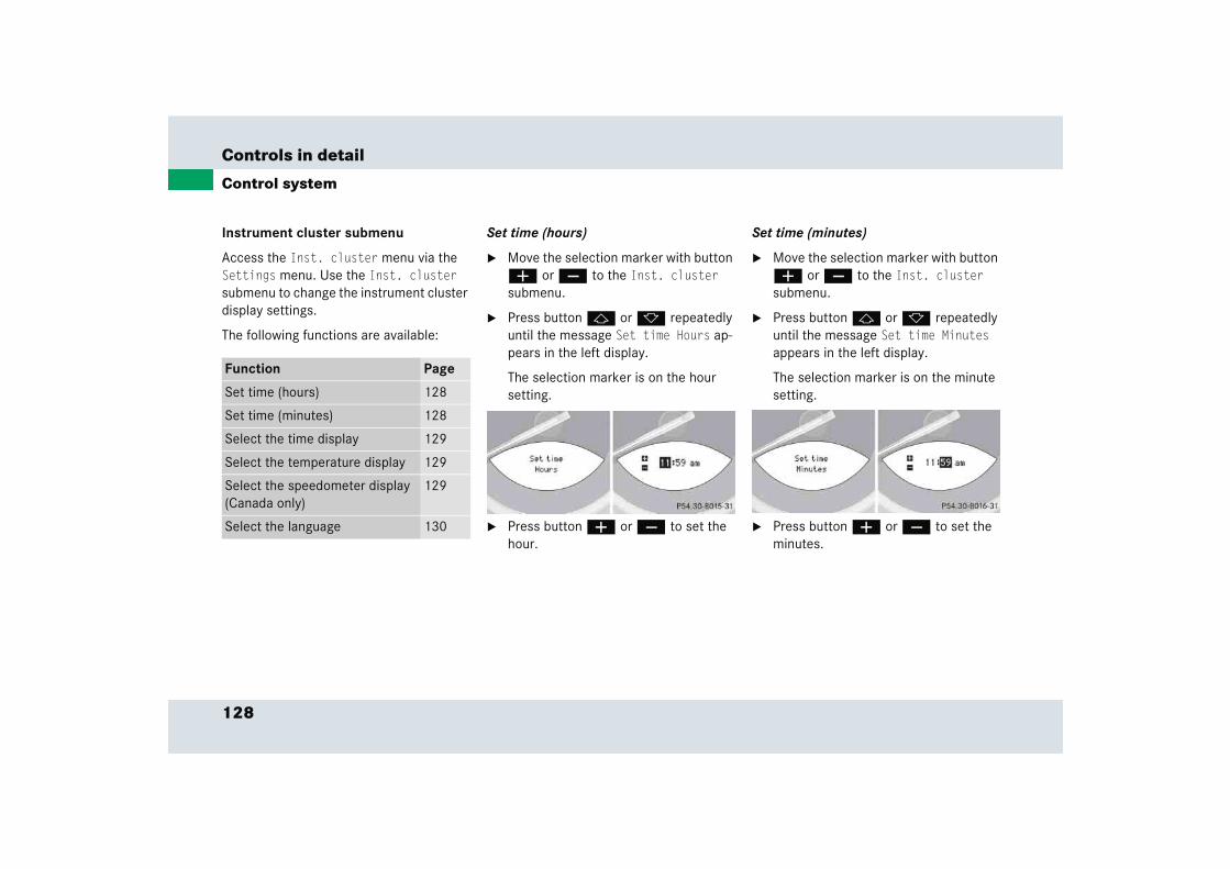
128
Controls in detail
Control system
Instrument cluster submenu
Access the Inst. cluster menu via the Settings menu. Use the Inst. cluster submenu to change the instrument cluster display settings.
The following functions are available:
Set time (hours)
� Move the selection marker with button æ or ç to the Inst. cluster submenu.
� Press button j or k repeatedly until the message Set time Hours ap-pears in the left display.
The selection marker is on the hour setting.
� Press button æ or ç to set the hour.
Set time (minutes)
� Move the selection marker with button æ or ç to the Inst. cluster submenu.
� Press button j or k repeatedly until the message Set time Minutes appears in the left display.
The selection marker is on the minute setting.
� Press button æ or ç to set the minutes.
Function Page
Set time (hours) 128
Set time (minutes) 128
Select the time display 129
Select the temperature display 129
Select the speedometer display (Canada only)
129
Select the language 130

129
Controls in detail
Control system
Selecting time display
� Move the selection marker with the æ or ç button to the Inst. cluster submenu.
� Press button j or k repeatedly until you see this message in the left display: Clock.
The selection marker is on the current setting.
� Press æ or ç to set the 12-hour or 24-hour time display mode.
Selecting temperature display mode
� Move the selection marker with button æ or ç to the Inst. cluster submenu.
� Press button j or k repeatedly until you see this message in the left display: Temp. indicator.
The selection marker is on the current setting.
� Press æ or ç to set temperature unit to degrees Celsius (°C) or degrees Fahrenheit (°F).
Selecting the speedometer display (Canada only)
� Move the selection marker with button æ or ç to the Inst. cluster submenu.
� Press button j or k repeatedly until you see this message in the left display: Speedometer.
The selection marker is on the current setting.
� Press æ or ç to set the speed-ometer units to Kilometres or Miles.
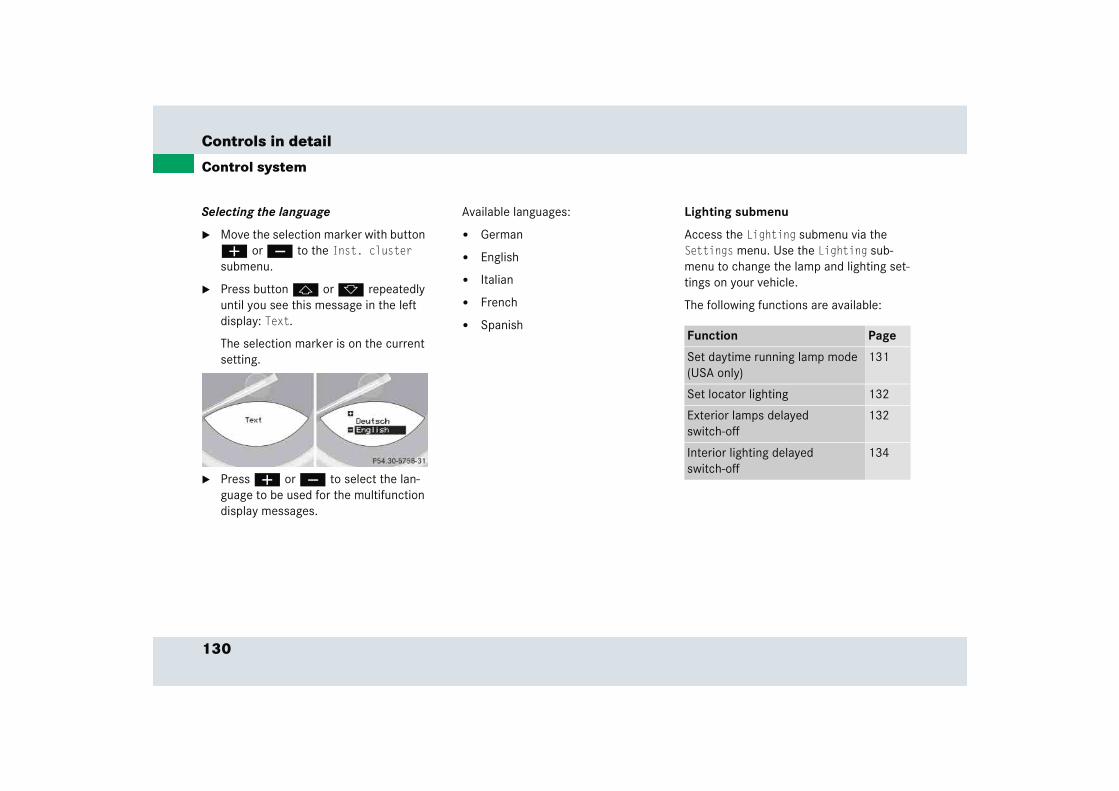
130
Controls in detail
Control system
Selecting the language
� Move the selection marker with button æ or ç to the Inst. cluster submenu.
� Press button j or k repeatedly until you see this message in the left display: Text.
The selection marker is on the current setting.
� Press æ or ç to select the lan-guage to be used for the multifunction display messages.
Available languages:
� German
� English
� Italian
� French
� Spanish
Lighting submenu
Access the Lighting submenu via the Settings menu. Use the Lighting sub-menu to change the lamp and lighting set-tings on your vehicle.
The following functions are available:
Function Page
Set daytime running lamp mode (USA only)
131
Set locator lighting 132
Exterior lamps delayed switch-off
132
Interior lighting delayed switch-off
134
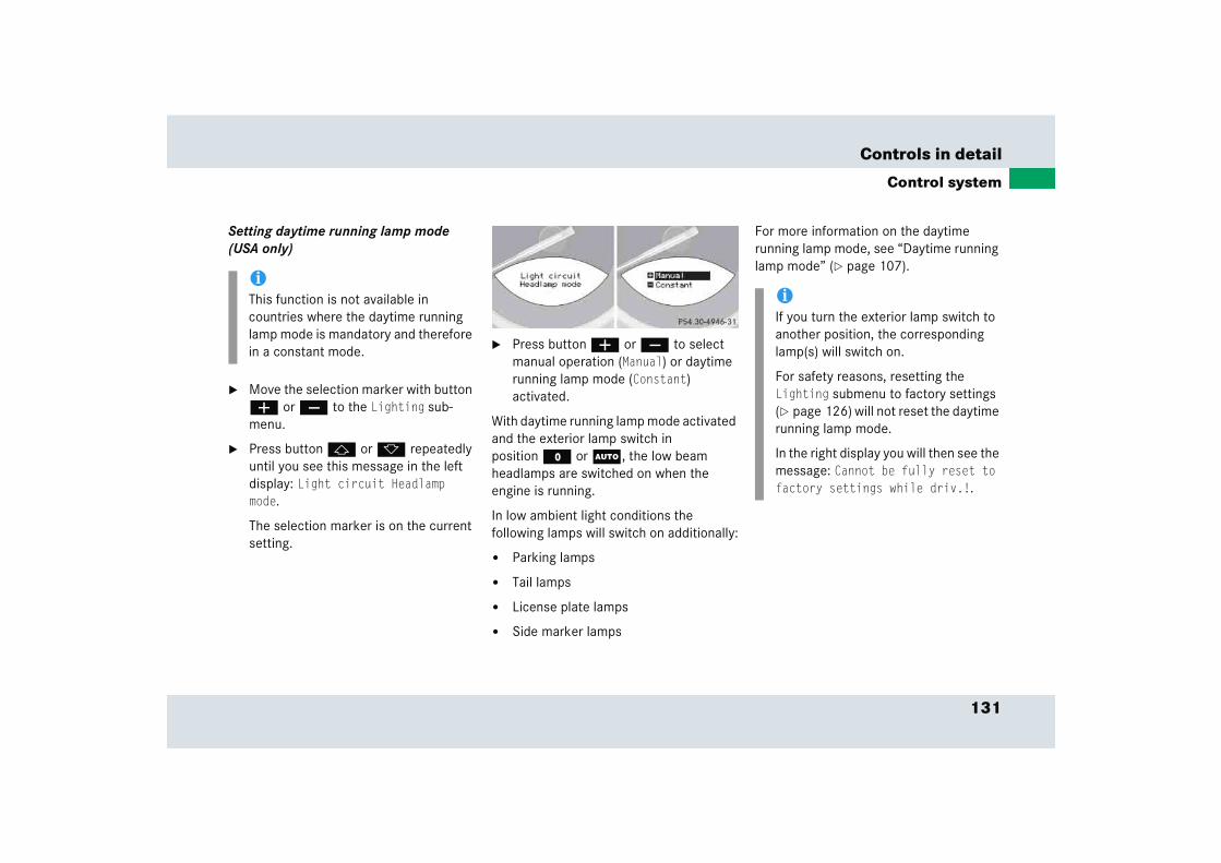
131
Controls in detail
Control system
Setting daytime running lamp mode (USA only)
� Move the selection marker with button æ or ç to the Lighting sub-menu.
� Press button j or k repeatedly until you see this message in the left display: Light circuit Headlamp mode.
The selection marker is on the current setting.
� Press button æ or ç to select manual operation (Manual) or daytime running lamp mode (Constant) activated.
With daytime running lamp mode activated and the exterior lamp switch in position M or U, the low beam headlamps are switched on when the engine is running.
In low ambient light conditions the following lamps will switch on additionally:
� Parking lamps
� Tail lamps
� License plate lamps
� Side marker lamps
For more information on the daytime running lamp mode, see “Daytime running lamp mode” (� page 107).
iThis function is not available in countries where the daytime running lamp mode is mandatory and therefore in a constant mode.
iIf you turn the exterior lamp switch to another position, the corresponding lamp(s) will switch on.
For safety reasons, resetting the Lighting submenu to factory settings (� page 126) will not reset the daytime running lamp mode.
In the right display you will then see the message: Cannot be fully reset to factory settings while driv.!.
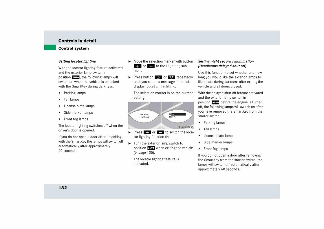
132
Controls in detail
Control system
Setting locator lighting
With the locator lighting feature activated and the exterior lamp switch in position U, the following lamps will switch on when the vehicle is unlocked with the SmartKey during darkness:
� Parking lamps
� Tail lamps
� License plate lamps
� Side marker lamps
� Front fog lamps
The locator lighting switches off when the driver’s door is opened.
If you do not open a door after unlocking with the SmartKey the lamps will switch off automatically after approximately 40 seconds.
� Move the selection marker with button æ or ç to the Lighting sub-menu.
� Press button j or k repeatedly until you see this message in the left display: Locator lighting.
The selection marker is on the current setting.
� Press æ or ç to switch the loca-tor lighting function On.
� Turn the exterior lamp switch to position U when exiting the vehicle (� page 105).
The locator lighting feature is activated.
Setting night security illumination (Headlamps delayed shut-off)
Use this function to set whether and how long you would like the exterior lamps to illuminate during darkness after exiting the vehicle and all doors closed.
With the delayed shut-off feature activated and the exterior lamp switch in position U before the engine is turned off, the following lamps will switch on after you have removed the SmartKey from the starter switch:
� Parking lamps
� Tail lamps
� License plate lamps
� Side marker lamps
� Front fog lamps
If you do not open a door after removing the SmartKey from the starter switch, the lamps will switch off automatically after approximately 60 seconds.

133
Controls in detail
Control system
� Move the selection marker with button æ or ç to the Lighting sub-menu.
� Press button j or k repeatedly until you see this message in the left display: Headlamps delayed switch-off.
The selection marker is on the current setting.
� Press æ or ç to select the de-sired lamp-on period.
You can select:
� 0 s, the delayed switch-off feature is deactivated
� 15 s, 30 s, 45 s or 60 s, the delayed switch-off feature is activated
� Turn the exterior lamp switch to position U before turning off the en-gine (� page 105).
The headlamps delayed switch-off fea-ture is activated
You can temporarily deactivate the de-layed switch-off feature:
� Before leaving the vehicle turn the SmartKey in the starter switch to position 0.
� Then turn it to position 2 and back to 0.
The delayed switch-off feature is deac-tivated. It will reactivate as soon as you reinsert the SmartKey in the starter switch.
iYou can reactivate this function within ten minutes by opening a door.
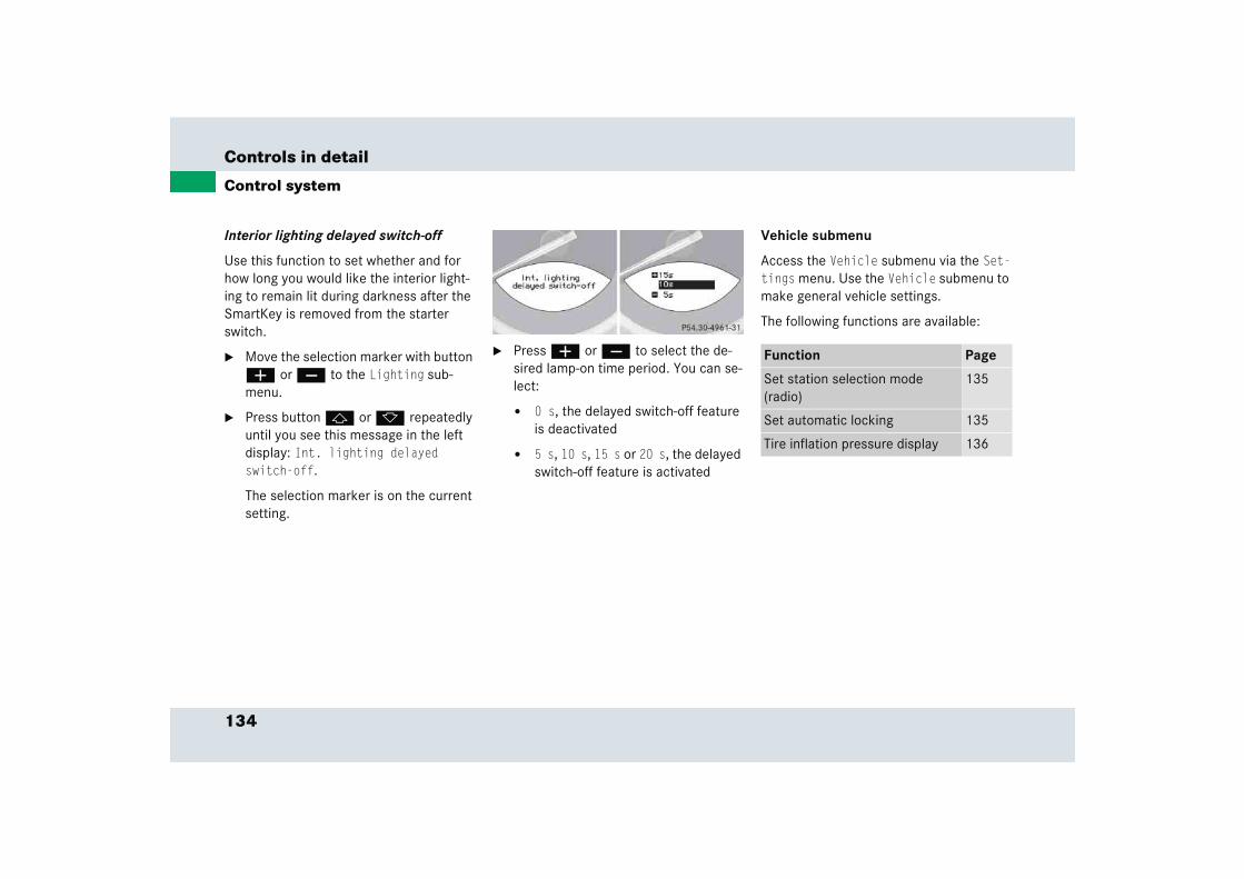
134
Controls in detail
Control system
Interior lighting delayed switch-off
Use this function to set whether and for how long you would like the interior light-ing to remain lit during darkness after the SmartKey is removed from the starter switch.
� Move the selection marker with button æ or ç to the Lighting sub-menu.
� Press button j or k repeatedly until you see this message in the left display: Int. lighting delayed switch-off.
The selection marker is on the current setting.
� Press æ or ç to select the de-sired lamp-on time period. You can se-lect:
� 0 s, the delayed switch-off feature is deactivated
� 5 s, 10 s, 15 s or 20 s, the delayed switch-off feature is activated
Vehicle submenu
Access the Vehicle submenu via the Set-tings menu. Use the Vehicle submenu to make general vehicle settings.
The following functions are available:
Function Page
Set station selection mode (radio)
135
Set automatic locking 135
Tire inflation pressure display 136
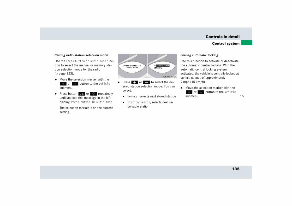
135
Controls in detail
Control system
Setting radio station selection mode
Use the Press button in audio mode func-tion to select the manual or memory sta-tion selection mode for the radio (� page 123).
� Move the selection marker with the æ or ç button to the Vehicle submenu.
� Press button j or k repeatedly until you see this message in the left display: Press button in audio mode.
The selection marker is on the current setting.
� Press æ or ç to select the de-sired station selection mode. You can select:
� Memory, selects next stored station
� Station search, selects next re-ceivable station
Setting automatic locking
Use this function to activate or deactivate the automatic central locking. With the automatic central locking system activated, the vehicle is centrally locked at vehicle speeds of approximately 9 mph (15 km/h).
� Move the selection marker with the æ or ç button to the Vehicle submenu. ��

136
Controls in detail
Control system
� Press button j or k repeatedly until you see this message in the left display: Automatic Door lock.
The selection marker is on the current setting.
� Press æ or ç to switch Automatic Door lock On or Off.
Tire inflation pressure display
Use this function to set the unit for the tire inflation pressure display.
� Move the selection marker with the æ or ç button to the Vehicle submenu.
� Press button j or k repeatedly until you see this message in the left display: Tire press. display.
The selection marker is on the current setting.
� Press æ or ç to select the de-sired tire inflation pressure unit.
Trip computer menu
Use the trip computer menu to call up statistical data on your vehicle.
The following information is available:
Function Page
Fuel consumption statistics after start
137
Fuel consumption statistics since last reset
137
Call up range (distance to empty) 138
iThe last function called up will reap-pear the next time you enter the trip computer menu.
��
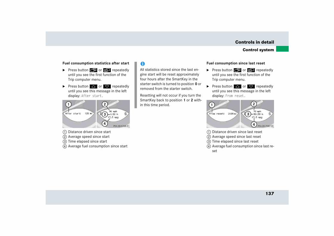
137
Controls in detail
Control system
Fuel consumption statistics after start
� Press button ÿ or è repeatedly until you see the first function of the Trip computer menu.
� Press button j or k repeatedly until you see this message in the left display: After start.
1 Distance driven since start2 Average speed since start3 Time elapsed since start4 Average fuel consumption since start
Fuel consumption since last reset
� Press button ÿ or è repeatedly until you see the first function of the Trip computer menu.
� Press button j or k repeatedly until you see this message in the left display: From reset.
1 Distance driven since last reset2 Average speed since last reset3 Time elapsed since last reset4 Average fuel consumption since last re-
set
iAll statistics stored since the last en-gine start will be reset approximately four hours after the SmartKey in the starter switch is turned to position 0 or removed from the starter switch.
Resetting will not occur if you turn the SmartKey back to position 1 or 2 with-in this time period.
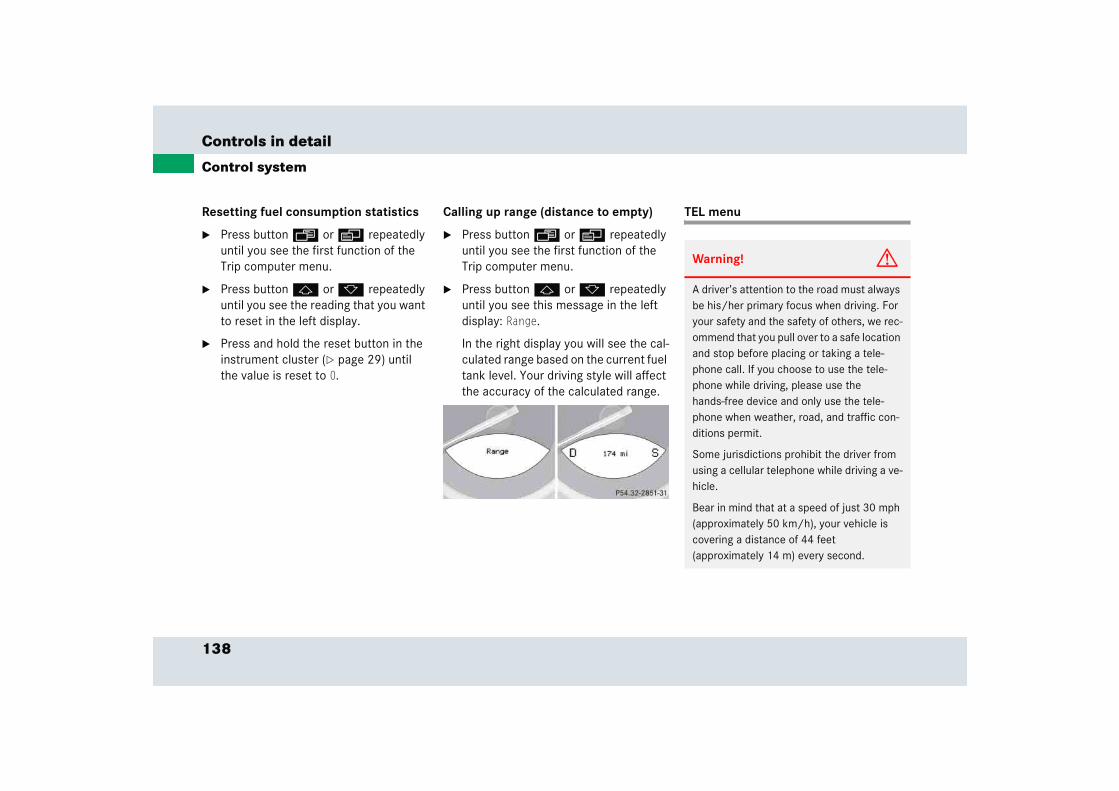
138
Controls in detail
Control system
Resetting fuel consumption statistics
� Press button ÿ or è repeatedly until you see the first function of the Trip computer menu.
� Press button j or k repeatedly until you see the reading that you want to reset in the left display.
� Press and hold the reset button in the instrument cluster (� page 29) until the value is reset to 0.
Calling up range (distance to empty)
� Press button ÿ or è repeatedly until you see the first function of the Trip computer menu.
� Press button j or k repeatedly until you see this message in the left display: Range.
In the right display you will see the cal-culated range based on the current fuel tank level. Your driving style will affect the accuracy of the calculated range.
TEL menu
Warning! G
A driver’s attention to the road must always be his/her primary focus when driving. For your safety and the safety of others, we rec-ommend that you pull over to a safe location and stop before placing or taking a tele-phone call. If you choose to use the tele-phone while driving, please use the hands-free device and only use the tele-phone when weather, road, and traffic con-ditions permit.
Some jurisdictions prohibit the driver from using a cellular telephone while driving a ve-hicle.
Bear in mind that at a speed of just 30 mph (approximately 50 km/h), your vehicle is covering a distance of 44 feet (approximately 14 m) every second.
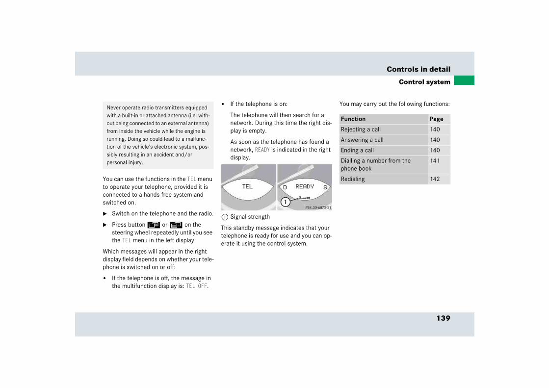
139
Controls in detail
Control system
You can use the functions in the TEL menu to operate your telephone, provided it is connected to a hands-free system and switched on.
� Switch on the telephone and the radio.
� Press button ÿ or è on the steering wheel repeatedly until you see the TEL menu in the left display.
Which messages will appear in the right display field depends on whether your tele-phone is switched on or off:
� If the telephone is off, the message in the multifunction display is: TEL OFF.
� If the telephone is on:
The telephone will then search for a network. During this time the right dis-play is empty.
As soon as the telephone has found a network, READY is indicated in the right display.
1 Signal strength
This standby message indicates that your telephone is ready for use and you can op-erate it using the control system.
You may carry out the following functions:Never operate radio transmitters equipped with a built-in or attached antenna (i.e. with-out being connected to an external antenna) from inside the vehicle while the engine is running. Doing so could lead to a malfunc-tion of the vehicle’s electronic system, pos-sibly resulting in an accident and/or personal injury.
Function Page
Rejecting a call 140
Answering a call 140
Ending a call 140
Dialling a number from the phone book
141
Redialing 142
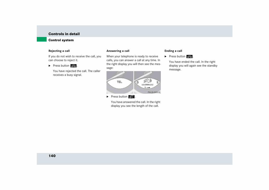
140
Controls in detail
Control system
Rejecting a call
If you do not wish to receive the call, you can choose to reject it.
� Press button ì.
You have rejected the call. The caller receives a busy signal.
Answering a call
When your telephone is ready to receive calls, you can answer a call at any time. In the right display you will then see the mes-sage:
� Press button í .
You have answered the call. In the right display you see the length of the call.
Ending a call
� Press button ì.
You have ended the call. In the right display you will again see the standby message.
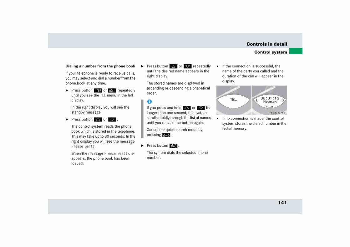
141
Controls in detail
Control system
Dialing a number from the phone book
If your telephone is ready to receive calls, you may select and dial a number from the phone book at any time.
� Press button ÿ or è repeatedly until you see the TEL menu in the left display.
In the right display you will see the standby message.
� Press button j or k .
The control system reads the phone book which is stored in the telephone. This may take up to 30 seconds. In the right display you will see the message Please wait!.
When the message Please wait! dis-appears, the phone book has been loaded.
� Press button j or k repeatedly until the desired name appears in the right display.
The stored names are displayed in ascending or descending alphabetical order.
� Press button í .
The system dials the selected phone number.
� If the connection is successful, the name of the party you called and the duration of the call will appear in the display.
� If no connection is made, the control system stores the dialed number in the redial memory.
iIf you press and hold j or k for longer than one second, the system scrolls rapidly through the list of names until you release the button again.
Cancel the quick search mode by pressing ì.

142
Controls in detail
Control system
Redialing
The control system stores the most recent-ly dialed phone numbers. This eliminates the need to search through your entire phone book.
� Press button ÿ or è repeatedly until you see the TEL menu in the left display.
In the right display you will see the standby message.
� Press button í .
In the right display you see the first number in the redial memory.
� Press button j or k repeatedly until the desired name appears in the right display.
� Press button í .
The control system dials the selected phone number.
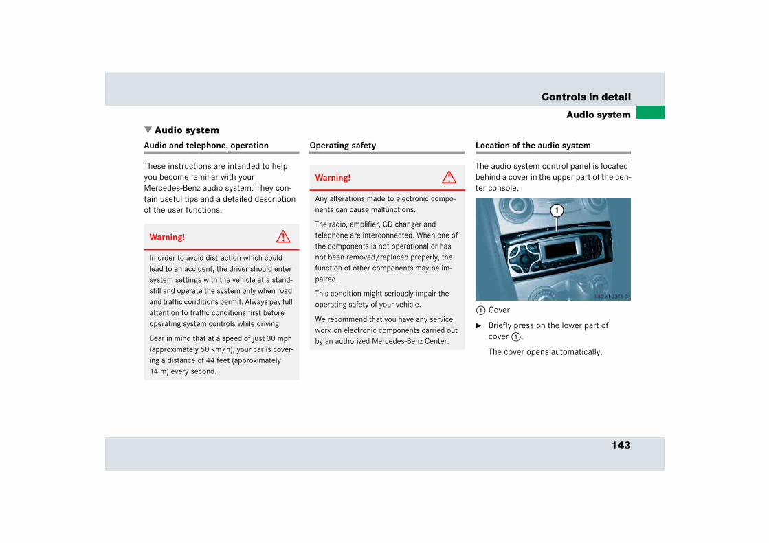
143
Controls in detail
Audio system
� Audio systemAudio and telephone, operation
These instructions are intended to help you become familiar with your Mercedes-Benz audio system. They con-tain useful tips and a detailed description of the user functions.
Operating safety Location of the audio system
The audio system control panel is located behind a cover in the upper part of the cen-ter console.
1 Cover
� Briefly press on the lower part of cover 1.
The cover opens automatically.
Warning! G
In order to avoid distraction which could lead to an accident, the driver should enter system settings with the vehicle at a stand-still and operate the system only when road and traffic conditions permit. Always pay full attention to traffic conditions first before operating system controls while driving.
Bear in mind that at a speed of just 30 mph (approximately 50 km/h), your car is cover-ing a distance of 44 feet (approximately 14 m) every second.
Warning! G
Any alterations made to electronic compo-nents can cause malfunctions.
The radio, amplifier, CD changer and telephone are interconnected. When one of the components is not operational or has not been removed/replaced properly, the function of other components may be im-paired.
This condition might seriously impair the operating safety of your vehicle.
We recommend that you have any service work on electronic components carried out by an authorized Mercedes-Benz Center.
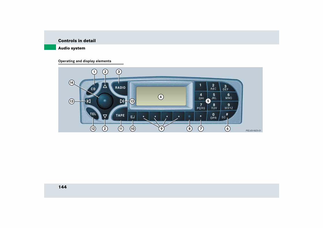
144
Controls in detail
Audio system
Operating and display elements
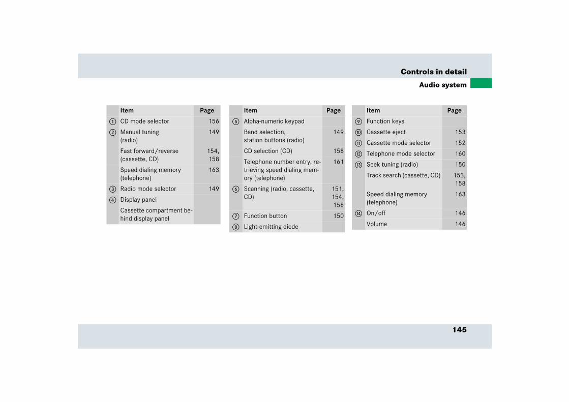
145
Controls in detail
Audio system
Item Page
1 CD mode selector 156
2 Manual tuning(radio)
149
Fast forward/reverse (cassette, CD)
154,158
Speed dialing memory (telephone)
163
3 Radio mode selector 149
4 Display panel
Cassette compartment be-hind display panel
Item Page
5 Alpha-numeric keypad
Band selection, station buttons (radio)
149
CD selection (CD) 158
Telephone number entry, re-trieving speed dialing mem-ory (telephone)
161
6 Scanning (radio, cassette, CD)
151,154,158
7 Function button 150
8 Light-emitting diode
Item Page
9 Function keys
a Cassette eject 153
b Cassette mode selector 152
c Telephone mode selector 160
d Seek tuning (radio) 150
Track search (cassette, CD) 153,158
Speed dialing memory(telephone)
163
e On/off 146
Volume 146
146
Controls in detail
Audio system
Button and soft key operation
In these instructions, the alpha-numeric keypad (right side of radio panel) and the function buttons (left side of radio panel) are referred to as “buttons”. The four keys below the display panel are referred to as “soft keys”.
Operation
Switching on/off
Switching on:
� Turn SmartKey in starter switch to position 1 or 2.
or
� Press control knob a.
Switching off:
� Remove SmartKey from starter switch.
or
� Press control knob a.
Adjusting the volume
� Turn control knob a.
The volume will increase or decrease depending on the direction turned.
Adjusting audio functions
Press the AUD key to call up the bass, tre-ble, balance and fader functions in the var-ious operating modes. Settings for bass and treble are stored separately for the AM and FM frequency bands, cassette mode and CD mode.
!Do not press directly on the display face. Otherwise the display will be damaged.
iIf the radio is switched on without the SmartKey in the starter switch, it will automatically switch off again after ap-proximately 30 minutes.
iThe volume setting can be selected separately for the telephone and audio system.
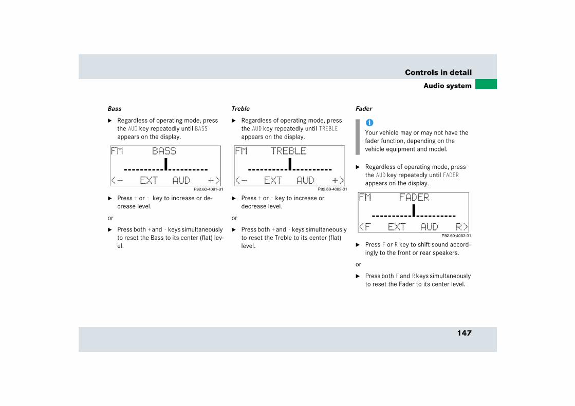
147
Controls in detail
Audio system
Bass
� Regardless of operating mode, press the AUD key repeatedly until BASS appears on the display.
� Press + or - key to increase or de-crease level.
or
� Press both + and - keys simultaneously to reset the Bass to its center (flat) lev-el.
Treble
� Regardless of operating mode, press the AUD key repeatedly until TREBLE appears on the display.
� Press + or - key to increase or decrease level.
or
� Press both + and - keys simultaneously to reset the Treble to its center (flat) level.
Fader
� Regardless of operating mode, press the AUD key repeatedly until FADER appears on the display.
� Press F or R key to shift sound accord-ingly to the front or rear speakers.
or
� Press both F and R keys simultaneously to reset the Fader to its center level.
iYour vehicle may or may not have the fader function, depending on the vehicle equipment and model.
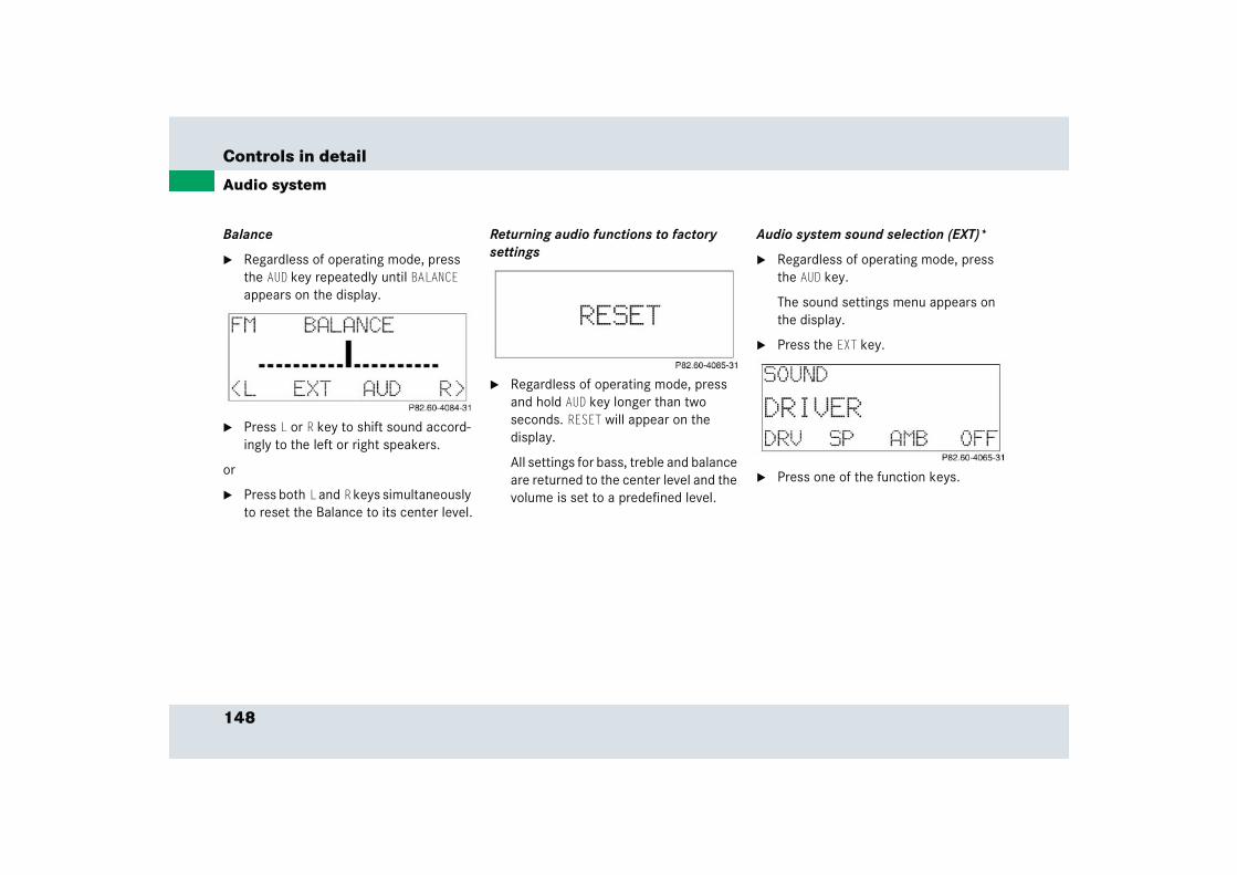
148
Controls in detail
Audio system
Balance
� Regardless of operating mode, press the AUD key repeatedly until BALANCE appears on the display.
� Press L or R key to shift sound accord-ingly to the left or right speakers.
or
� Press both L and R keys simultaneously to reset the Balance to its center level.
Returning audio functions to factory settings
� Regardless of operating mode, press and hold AUD key longer than two seconds. RESET will appear on the display.
All settings for bass, treble and balance are returned to the center level and the volume is set to a predefined level.
Audio system sound selection (EXT)*
� Regardless of operating mode, press the AUD key.
The sound settings menu appears on the display.
� Press the EXT key.
� Press one of the function keys.
149
Controls in detail
Audio system
You can select from among the following settings:
� DRV: The tone level is set to the Driver position; sound is directed toward the passengers.
� SP: The tone level is set for Speech, optimizing the sound for the spoken word.
� AMB: The tone level is set for Ambience, producing a three-dimensional sound.
� OFF: The audio system sound selection is turned off.
Telephone muting
The radio will switch to telephone mode when a call is incoming. The current audio source is muted.
Radio operation
Selecting radio mode
� Press b button.
� You can now receive radio stations over the analog FM, AM or WB station frequencies.
Analog station frequencies
Selecting the band
You can select from among FM, AM or WB frequency bands.
Weather band (� page 152).
� Press FM, AM or WB key repeatedly un-til desired band has been selected.
The FM, AM and WB frequency bands are called up one after the other.
The frequency band currently selected appears in the upper left-hand corner of the display.
Selecting a station
The following options are available for selecting a station:
� Direct frequency band input (� page 150)
� Manual tuning (� page 150)
� Automatic seek tuning (� page 150)
� Scan tuning (� page 151)
� Preset buttons (� page 151)
� Automatic station memory (Autostore) (� page 151)
iFM frequency band:FM 87.7......107.9 MHz
AM frequency band:MW (medium wave) 530......1710 KHz
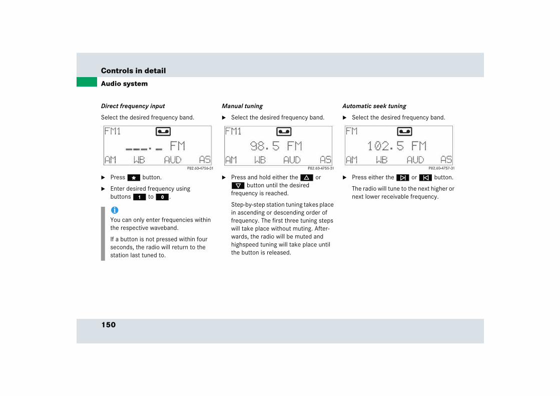
150
Controls in detail
Audio system
Direct frequency input
Select the desired frequency band.
� Press “ button.
� Enter desired frequency using buttons 4 to M.
Manual tuning
� Select the desired frequency band.
� Press and hold either the d or c button until the desired frequency is reached.
Step-by-step station tuning takes place in ascending or descending order of frequency. The first three tuning steps will take place without muting. After-wards, the radio will be muted and highspeed tuning will take place until the button is released.
Automatic seek tuning
� Select the desired frequency band.
� Press either the f or e button.
The radio will tune to the next higher or next lower receivable frequency.
iYou can only enter frequencies within the respective waveband.
If a button is not pressed within four seconds, the radio will return to the station last tuned to.
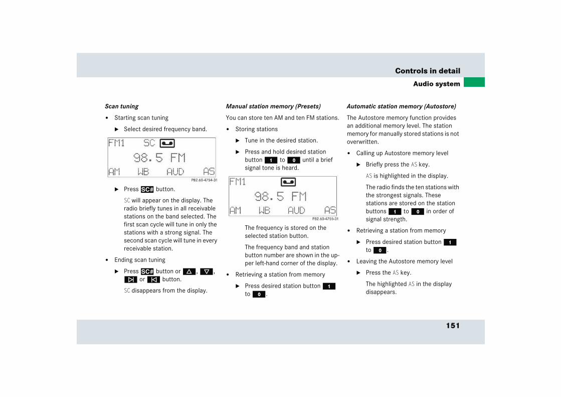
151
Controls in detail
Audio system
Scan tuning
� Starting scan tuning
� Select desired frequency band.
� Press2 button.
SC will appear on the display. The radio briefly tunes in all receivable stations on the band selected. The first scan cycle will tune in only the stations with a strong signal. The second scan cycle will tune in every receivable station.
� Ending scan tuning
� Press2 button or d, c, f or e button.
SC disappears from the display.
Manual station memory (Presets)
You can store ten AM and ten FM stations.
� Storing stations
� Tune in the desired station.
� Press and hold desired station button 4 to M until a brief signal tone is heard.
The frequency is stored on the selected station button.
The frequency band and station button number are shown in the up-per left-hand corner of the display.
� Retrieving a station from memory
� Press desired station button 4 to M.
Automatic station memory (Autostore)
The Autostore memory function provides an additional memory level. The station memory for manually stored stations is not overwritten.
� Calling up Autostore memory level
� Briefly press the AS key.
AS is highlighted in the display.
The radio finds the ten stations with the strongest signals. These stations are stored on the station buttons 4 to M in order of signal strength.
� Retrieving a station from memory
� Press desired station button 4 to M.
� Leaving the Autostore memory level
� Press the AS key.
The highlighted AS in the display disappears.
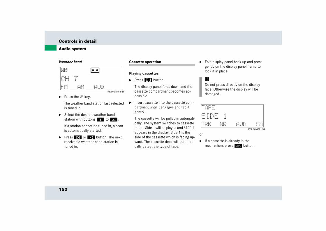
152
Controls in detail
Audio system
Weather band
� Press the WB key.
The weather band station last selected is tuned in.
� Select the desired weather band station with buttons 4 to 7.
If a station cannot be tuned in, a scan is automatically started.
� Press f or e button. The next receivable weather band station is tuned in.
Cassette operation
Playing cassettes
� Press3 button.
The display panel folds down and the cassette compartment becomes ac-cessible.
� Insert cassette into the cassette com-partment until it engages and tap it gently.
The cassette will be pulled in automati-cally. The system switches to cassette mode. Side 1 will be played and SIDE 1 appears in the display. Side 1 is the side of the cassette which is facing up-ward. The cassette deck will automati-cally detect the type of tape.
� Fold display panel back up and press gently on the display panel frame to lock it in place.
or
� If a cassette is already in the mechanism, press j button.
!Do not press directly on the display face. Otherwise the display will be damaged.

153
Controls in detail
Audio system
Track selection
� Press the TRK key.
The current track will be displayed as SIDE 1 or SIDE 2.
� You can switch sides at any time.The side will be changed automatically at the end of the tape.
Cassette eject
� Press eject button3.
The display folds down and the cas-sette is ejected. The system will switch back to radio mode automatically.
� Fold display panel back up and press gently on the display panel frame to lock it.
Track search
Track search forward
� Press f button.
SEEK FWD will appear in the display. Track search will run the tape forward to the start of the next track and switch to Play.
iA warning signal will sound after 20 seconds if the display panel is left in the down position. Fold display panel back up. If the display panel is not closed, a warning signal will sound and the radio will be muted.
!Do not press directly on the display face. Otherwise the display will be damaged.
iThe cassette will not be ejected when the system is switched off or switched to another operating mode.
iThe beginning of a track can only be found if there is pause of at least four seconds between tracks.
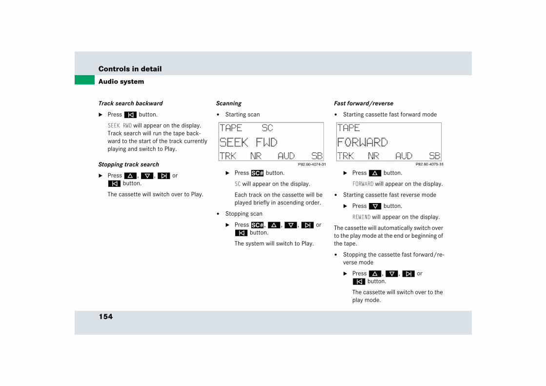
154
Controls in detail
Audio system
Track search backward
� Press e button.
SEEK RWD will appear on the display. Track search will run the tape back-ward to the start of the track currently playing and switch to Play.
Stopping track search
� Press d, c, f or e button.
The cassette will switch over to Play.
Scanning
� Starting scan
� Press2 button.
SC will appear on the display.
Each track on the cassette will be played briefly in ascending order.
� Stopping scan
� Press2, d, c, f or e button.
The system will switch to Play.
Fast forward/reverse
� Starting cassette fast forward mode
� Press d button.
FORWARD will appear on the display.
� Starting cassette fast reverse mode
� Press c button.
REWIND will appear on the display.
The cassette will automatically switch over to the play mode at the end or beginning of the tape.
� Stopping the cassette fast forward/re-verse mode
� Press d, c, f or e button.
The cassette will switch over to the play mode.
155
Controls in detail
Audio system
Skipping blank sections (skip blank)
Switching on the skip blank function
� Press the SB key.
SB is highlighted in the display.
If the system does not detect a sound signal, the cassette will automatically fast forward to the next sound signal.
Switching off the skip blank function
� Press the SB key.
The highlighted SB in the display disap-pears.
Dolby NR1 (noise reduction system)
To enable optimum sound reproduction of cassettes recorded using Dolby B NR, the Dolby NR system should be switched on.
Switching on
� Press the NR key.
NR is highlighted in the display.
Switching off
� Press the NR key.
The highlighted NR in the display disap-pears.
1 DOLBY and the double-D symbol Ù are trade-marks of Dolby Laboratories Licensing Corpora-tion.The Dolby noise reduction system is manufactured under license from Dolby Laboratories Licensing Corporation.
iThe Dolby NR function should be switched off when playing cassettes not recorded with Dolby B NR.
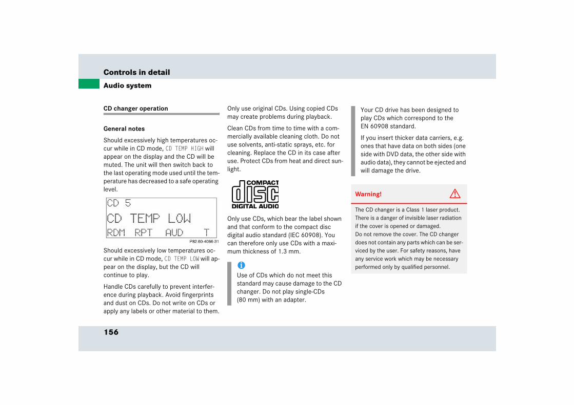
156
Controls in detail
Audio system
CD changer operation
General notes
Should excessively high temperatures oc-cur while in CD mode, CD TEMP HIGH will appear on the display and the CD will be muted. The unit will then switch back to the last operating mode used until the tem-perature has decreased to a safe operating level.
Should excessively low temperatures oc-cur while in CD mode, CD TEMP LOW will ap-pear on the display, but the CD will continue to play.
Handle CDs carefully to prevent interfer-ence during playback. Avoid fingerprints and dust on CDs. Do not write on CDs or apply any labels or other material to them.
Only use original CDs. Using copied CDs may create problems during playback.
Clean CDs from time to time with a com-mercially available cleaning cloth. Do not use solvents, anti-static sprays, etc. for cleaning. Replace the CD in its case after use. Protect CDs from heat and direct sun-light.
Only use CDs, which bear the label shown and that conform to the compact disc digital audio standard (IEC 60908). You can therefore only use CDs with a maxi-mum thickness of 1.3 mm.
iUse of CDs which do not meet this standard may cause damage to the CD changer. Do not play single-CDs (80 mm) with an adapter.
Your CD drive has been designed to play CDs which correspond to the EN 60908 standard.
If you insert thicker data carriers, e.g. ones that have data on both sides (one side with DVD data, the other side with audio data), they cannot be ejected and will damage the drive.
Warning! G
The CD changer is a Class 1 laser product. There is a danger of invisible laser radiation if the cover is opened or damaged.Do not remove the cover. The CD changer does not contain any parts which can be ser-viced by the user. For safety reasons, have any service work which may be necessary performed only by qualified personnel.
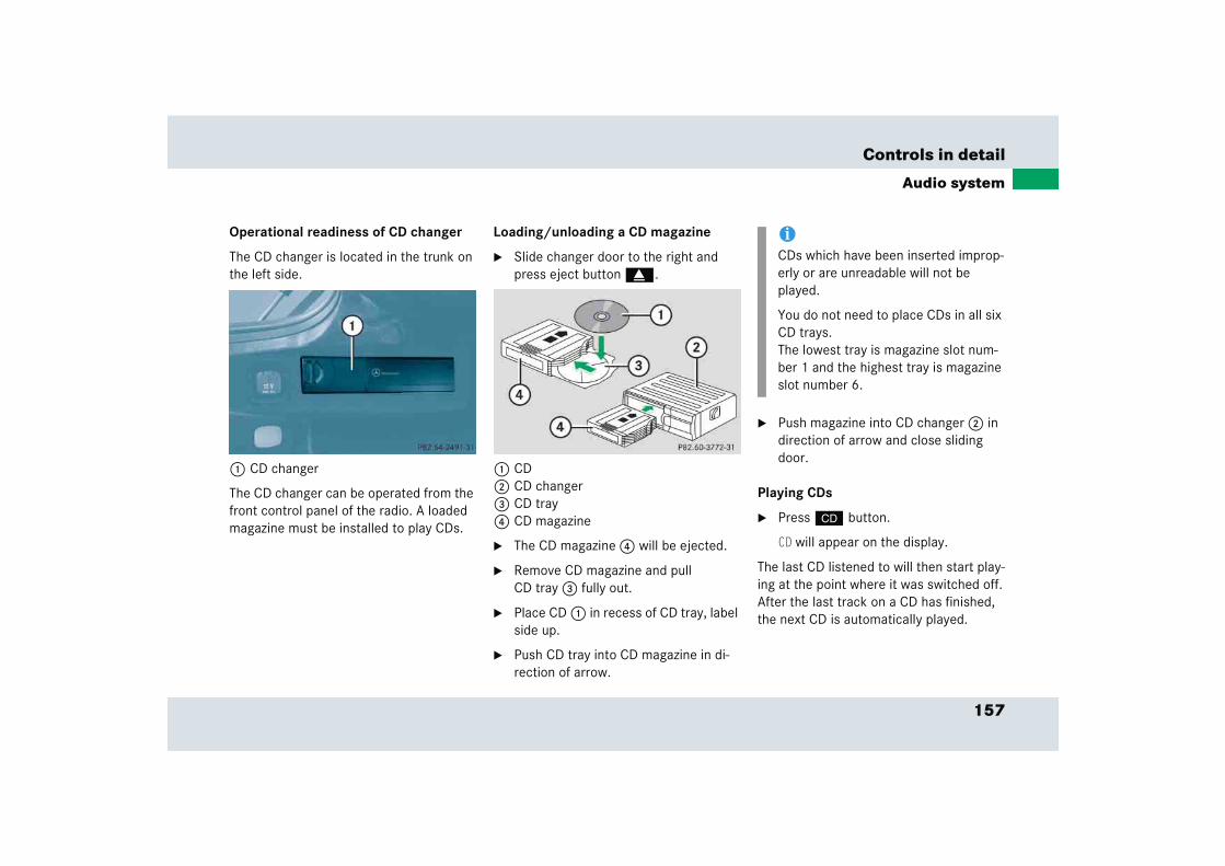
157
Controls in detail
Audio system
Operational readiness of CD changer
The CD changer is located in the trunk on the left side.
1 CD changer
The CD changer can be operated from the front control panel of the radio. A loaded magazine must be installed to play CDs.
Loading/unloading a CD magazine
� Slide changer door to the right and press eject button g.
1 CD2 CD changer3 CD tray4 CD magazine
� The CD magazine 4 will be ejected.
� Remove CD magazine and pull CD tray 3 fully out.
� Place CD 1 in recess of CD tray, label side up.
� Push CD tray into CD magazine in di-rection of arrow.
� Push magazine into CD changer 2 in direction of arrow and close sliding door.
Playing CDs
� Press i button.
CD will appear on the display.
The last CD listened to will then start play-ing at the point where it was switched off.After the last track on a CD has finished, the next CD is automatically played.
iCDs which have been inserted improp-erly or are unreadable will not be played.
You do not need to place CDs in all six CD trays.The lowest tray is magazine slot num-ber 1 and the highest tray is magazine slot number 6.
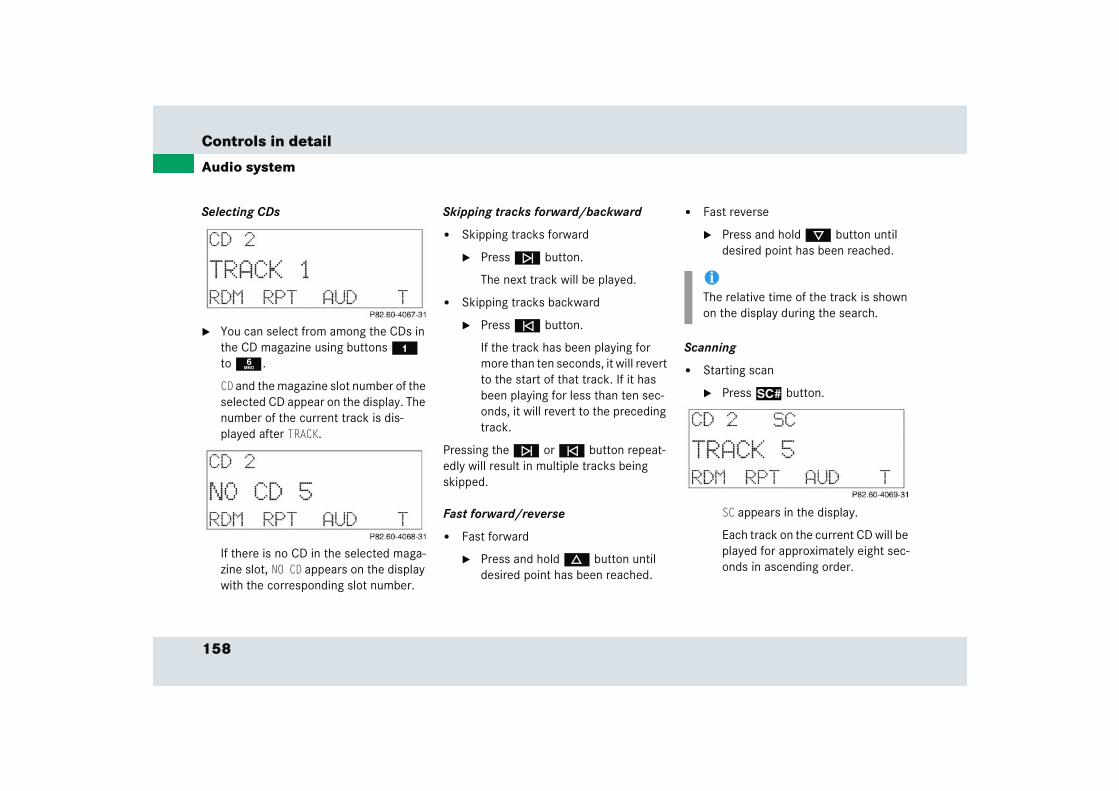
158
Controls in detail
Audio system
Selecting CDs
� You can select from among the CDs in the CD magazine using buttons 4 to 6.
CD and the magazine slot number of the selected CD appear on the display. The number of the current track is dis-played after TRACK.
If there is no CD in the selected maga-zine slot, NO CD appears on the display with the corresponding slot number.
Skipping tracks forward/backward
� Skipping tracks forward
� Press f button.
The next track will be played.
� Skipping tracks backward
� Press e button.
If the track has been playing for more than ten seconds, it will revert to the start of that track. If it has been playing for less than ten sec-onds, it will revert to the preceding track.
Pressing the f or e button repeat-edly will result in multiple tracks being skipped.
Fast forward/reverse
� Fast forward
� Press and hold d button until desired point has been reached.
� Fast reverse
� Press and hold c button until desired point has been reached.
Scanning
� Starting scan
� Press2 button.
SC appears in the display.
Each track on the current CD will be played for approximately eight sec-onds in ascending order.
iThe relative time of the track is shown on the display during the search.

159
Controls in detail
Audio system
� Ending scan
� Press2, d, c, f or e button.
Random play
The random play function (RDM) plays the tracks on the current CD in random order.
� Switching on random play
� Press the RDM key.
RDM is highlighted in the display.
� Switching off random play
� Press the RDM key.
The highlighted RDM in the display disappears.
Repeat
The repeat function (RPT) repeats the cur-rent track.
� Switching on repeat:
� Press the RPT key.
RPT is highlighted in the display.
� Switching off repeat:
� Press the RPT key.
The highlighted RPT in the display disappears.
Track and time display
� Press the T key.
The number of the track being played and the elapsed playing time appear in the display.
� Press the T key.
The total number of tracks and the total playing time of the CD appear in the display.
The CD main menu appears again after eight seconds.
iThe Random play and Repeat function cannot be used simultaneously.

160
Controls in detail
Audio system
Telephone operation Various car telephone functions and oper-ating steps for the car telephone can be performed and displayed via the audio sys-tem.
Further operating instructions not covered here can be found in the operating instructions for the multifunction steering wheel and the telephone.
Switching on the telephone
� Press h button.
If you have programmed an unlock code for the telephone, you must enter the code now.
� Enter the code using buttons 4 to M.
� If necessary, correct number entered with the CLR key. Press key briefly to delete the last digit entered; press key and hold to delete the complete num-ber.
� Press the OK key after entering correct code.
The telephone is unlocked. If you have entered the wrong code, you must re-peat the entering procedure with the correct code.
Switching off the telephone
� Press h button repeatedly until PHONE OFF appears in the display.
The receiving symbol in the display disappears.
Adjusting the volume
� Turn control knob a during tele-phone operation.
The volume increases or decreases de-pending on the direction in which the knob is turned.
Warning! G
Please do not forget that your primary re-sponsibility is to drive the vehicle. A driver’s attention to the road must always be his/her primary focus when driving. For your safety and the safety of others, we rec-ommend that you pull over to a safe location and stop before placing or taking a tele-phone call.
If you choose to use the telephone1 while driving, please use the hands-free device and only use the telephone when road, weather and traffic conditions permit. Some jurisdictions prohibit the driver from using a cellular telephone while driving a vehicle.
Bear in mind that at a speed of just 30 mph (approximately 50 km/h), your vehicle is covering a distance of 44 feet (approximately 14 m) every second.
1 Observe all legal requirements.
iThe volume can be adjusted separately for the telephone and radio.
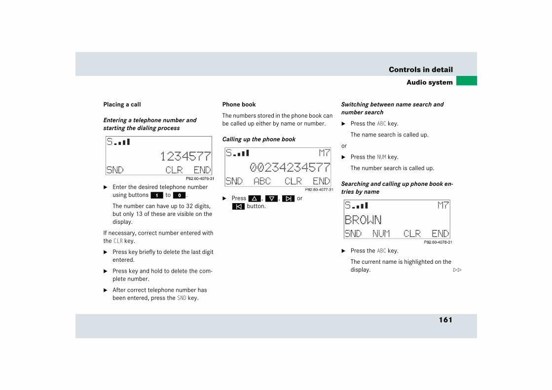
161
Controls in detail
Audio system
Placing a call
Entering a telephone number and starting the dialing process
� Enter the desired telephone number using buttons 4 to M.
The number can have up to 32 digits, but only 13 of these are visible on the display.
If necessary, correct number entered with the CLR key.
� Press key briefly to delete the last digit entered.
� Press key and hold to delete the com-plete number.
� After correct telephone number has been entered, press the SND key.
Phone book
The numbers stored in the phone book can be called up either by name or number.
Calling up the phone book
� Press d, c, f or e button.
Switching between name search and number search
� Press the ABC key.
The name search is called up.
or
� Press the NUM key.
The number search is called up.
Searching and calling up phone book en-tries by name
� Press the ABC key.
The current name is highlighted on the display. ��
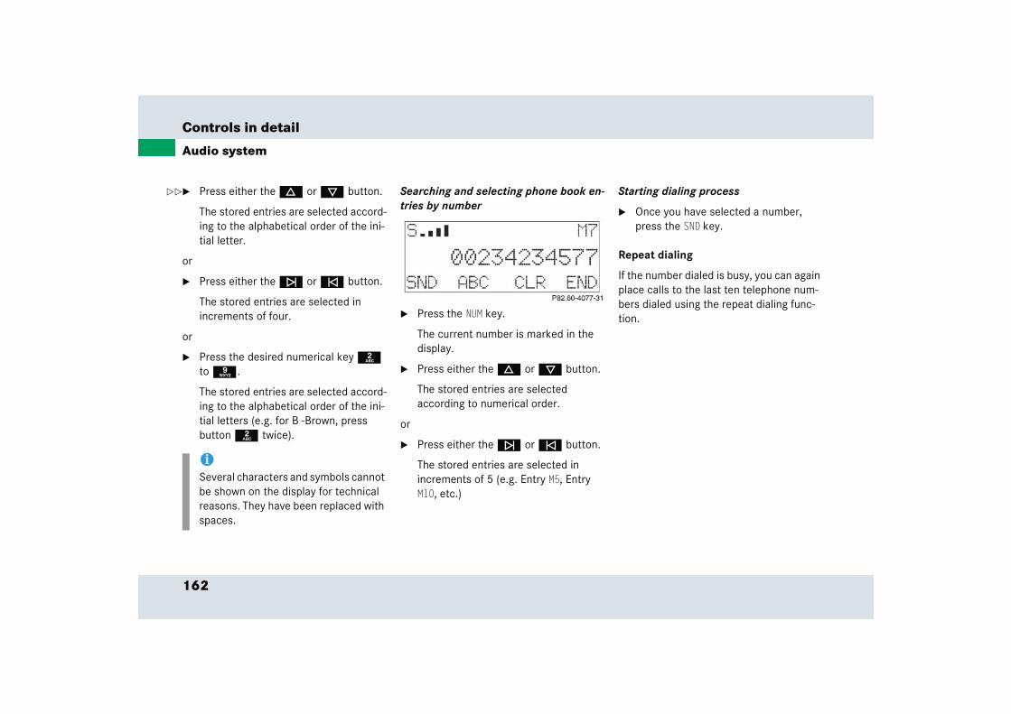
162
Controls in detail
Audio system
� Press either the d or c button.
The stored entries are selected accord-ing to the alphabetical order of the ini-tial letter.
or
� Press either the f or e button.
The stored entries are selected in increments of four.
or
� Press the desired numerical key 2 to 9.
The stored entries are selected accord-ing to the alphabetical order of the ini-tial letters (e.g. for B -Brown, press button 2 twice).
Searching and selecting phone book en-tries by number
� Press the NUM key.
The current number is marked in the display.
� Press either the d or c button.
The stored entries are selected according to numerical order.
or
� Press either the f or e button.
The stored entries are selected in increments of 5 (e.g. Entry M5, Entry M10, etc.)
Starting dialing process
� Once you have selected a number, press the SND key.
Repeat dialing
If the number dialed is busy, you can again place calls to the last ten telephone num-bers dialed using the repeat dialing func-tion.
iSeveral characters and symbols cannot be shown on the display for technical reasons. They have been replaced with spaces.
��
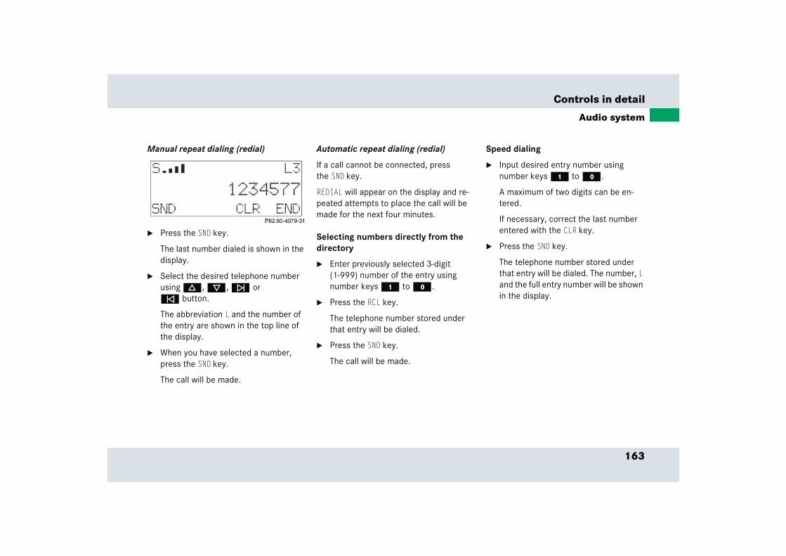
163
Controls in detail
Audio system
Manual repeat dialing (redial)
� Press the SND key.
The last number dialed is shown in the display.
� Select the desired telephone number using d, c, f or e button.
The abbreviation L and the number of the entry are shown in the top line of the display.
� When you have selected a number, press the SND key.
The call will be made.
Automatic repeat dialing (redial)
If a call cannot be connected, press the SND key.
REDIAL will appear on the display and re-peated attempts to place the call will be made for the next four minutes.
Selecting numbers directly from the directory
� Enter previously selected 3-digit (1-999) number of the entry using number keys 4 to M.
� Press the RCL key.
The telephone number stored under that entry will be dialed.
� Press the SND key.
The call will be made.
Speed dialing
� Input desired entry number using number keys 4 to M.
A maximum of two digits can be en-tered.
If necessary, correct the last number entered with the CLR key.
� Press the SND key.
The telephone number stored under that entry will be dialed. The number, L and the full entry number will be shown in the display.
164
Controls in detail
Audio system
Quick-dialing
� Press one of the desired number buttons 4 to M longer than one second.
The telephone number saved under that number will be dialed.
Emergency calls “911”
The following describes how to dial a “911” emergency call using the audio system head unit when a Mercedes-Benz specified mobile phone is inserted in the phone cra-dle. Unless otherwise specified, the de-scriptions refer to the audio system head unit.
Consult the separate telephone operating instructions that came with your mobile phone for information on how to place a “911” emergency call on the mobile phone.
The following conditions must be met for a “911” emergency call:
� Telephone must be switched on.
� The corresponding mobile communica-tions network must be available.
If you cannot make an emergency call, you will have to initiate rescue measures yourself.
!Please be aware that button 4 might already be reserved for an emer-gency call number.
Warning! G
The “911” emergency call system is a public service. Using it without due cause is a crim-inal offense.
iEmergency calls may not be possible with all telephone networks or if certain network services and/or telephone functions are active. Check with your local service providers.
165
Controls in detail
Audio system
Placing a “911” emergency call using audio head unit with the phone locked
� Press h button to switch to telephone operation.
CODE? appears in the audio display.
� Press button 4 on the audio head unit until 911 appears in the audio dis-play.
911 appears in the audio display while the telephone establishes the connec-tion.
� Wait until the emergency call center answers, then describe the emergency.
Placing a “911” emergency call using audio head unit with the phone unlocked
� Press h button to switch to telephone operation.
� Enter 911 using the number keypad on the audio head unit.
� Press the SND key for dialing to begin.
The telephone establishes the connec-tion.
� Wait until the emergency call center answers, then describe the emergency.
Accepting an incoming call
Accepting an incoming call in telephone mode
With an incoming call, a ringing tone can be heard and the caller’s telephone num-ber, or the name under which this tele-phone number has been saved in the telephone book, appears on the display. If the caller’s number is not transmitted, CALL will appear in the display.
� Press the SND key to accept call.

166
Controls in detail
Audio system
Accepting an incoming call in cassette, CD or radio mode
If the telephone is activated in the back-ground (receiving symbol S visible on dis-play), the audio source is muted when a call is received. The ringing tone is heard and the caller’s telephone number or the name under which this telephone number has been saved in the telephone book ap-pears on the display. If the caller’s number is not transmitted, CALL appears in the dis-play.
� Press the SND key to accept the call.
Muting a call
It is possible to mute a call; the caller is then no longer able to hear you.
Mute on
� Press the MUT key.
Mute off
� Press the MUT key.
Terminating a call
� Press the END key.
The current call is terminated.
Call waiting
If you receive another call during an al-ready active call, you can accept the sec-ond call and switch between the two.
Accepting a second call
� Press the SND key.
You are connected with the second caller, the first call is muted.
Switching between the calls
� Press the SND key.
Terminating the second call
� Press the END key.
The current call will be terminated. You are connected with the muted call again.
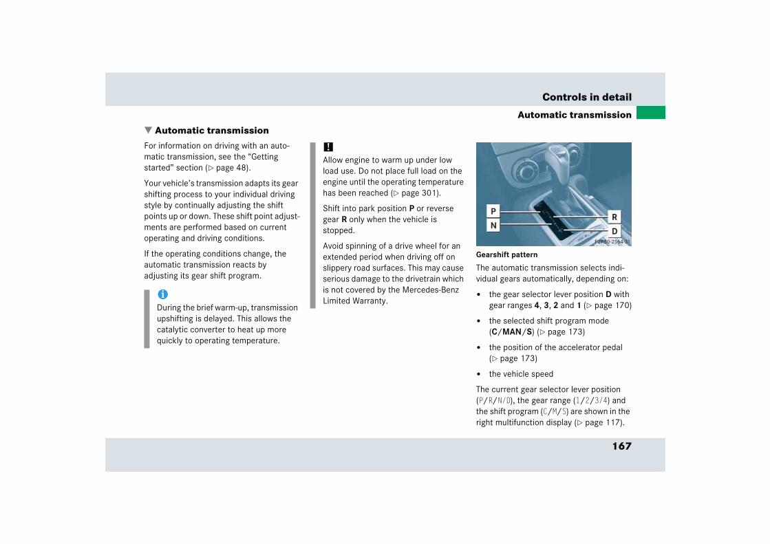
167
Controls in detail
Automatic transmission
� Automatic transmissionFor information on driving with an auto-matic transmission, see the “Getting started” section (� page 48).
Your vehicle’s transmission adapts its gear shifting process to your individual driving style by continually adjusting the shift points up or down. These shift point adjust-ments are performed based on current operating and driving conditions.
If the operating conditions change, the automatic transmission reacts by adjusting its gear shift program.
Gearshift pattern
The automatic transmission selects indi-vidual gears automatically, depending on:
� the gear selector lever position D with gear ranges 4, 3, 2 and 1 (� page 170)
� the selected shift program mode (C/MAN/S) (� page 173)
� the position of the accelerator pedal (� page 173)
� the vehicle speed
The current gear selector lever position (P/R/N/D), the gear range (1/2/3/4) and the shift program (C/M/S) are shown in the right multifunction display (� page 117).
iDuring the brief warm-up, transmission upshifting is delayed. This allows the catalytic converter to heat up more quickly to operating temperature.
!Allow engine to warm up under low load use. Do not place full load on the engine until the operating temperature has been reached (� page 301).
Shift into park position P or reverse gear R only when the vehicle is stopped.
Avoid spinning of a drive wheel for an extended period when driving off on slippery road surfaces. This may cause serious damage to the drivetrain which is not covered by the Mercedes-Benz Limited Warranty.
168
Controls in detail
Automatic transmission
An additional indication of the current gear selector lever position can be found on the cover of the shifting-gate.
When the gear selector lever is in position D, you can influence transmission shifting by
� limiting the shift range
� changing gears manually
One-touch gearshifting
Even with an automatic transmission you can change the gears manually when the gear selector lever is in position D.
Downshifting
� Briefly press the gear selector lever to the left in the D- direction.
The transmission will shift from the cur-rent gear to the next lower gear. This action simultaneously limits the gear range of the transmission (� page 170).
Warning! G
It is dangerous to shift the gear selector lever out of P or N if the engine speed is higher than idle speed. If your foot is not firmly on the brake pedal, the vehicle could accelerate quickly forward or reverse. You could lose control of the vehicle and hit someone or something. Only shift into gear when the engine is idling normally and when your right foot is firmly on the brake pedal.
169
Controls in detail
Automatic transmission
Upshifting
� Briefly press the gear selector lever to the right in the D+ direction.
The transmission will shift from the current gear to the next higher gear as permitted by the shift program. This action simul-taneously extends the gear range of the transmission.
Canceling gear range limit
� Press and hold the gear selector lever in the D+ direction until D reappears in the right multifunction display.
The transmission will shift from the current gear range directly to gear range D.
Shifting into optimal gear range
� Press and hold the gear selector lever in the D- direction.
The transmission will automatically select the gear range suited for optimal acceleration and deceleration. This will involve shifting down one or more gears.
Warning! G
On slippery road surfaces, never downshift in order to obtain braking action. This could result in drive wheel slip and reduced vehicle control. Your vehicle’s ABS will not prevent this type of loss of control.
iTo avoid overrevving the engine when the gear selector lever is moved to the D- direction, the transmission will not shift to a lower gear if the engine’s max. speed would be exceeded.

170
Controls in detail
Automatic transmission
Gear ranges
With the gear selector lever in position D, you can limit the transmission’s gear range by pressing the gear selector lever to the left (D-), and reverse the gear range limit by pressing the gear selector lever to the right (D+).
The selected gear range appears in the right multifunction display (� page 117). If you press on the accelerator when the en-gine has reached its rpm limit, the trans-mission will upshift beyond any gear range limit selected.
iIf, when driving in shift program mode C and S the maximum engine speed for the gear range has been reached, the transmission shifts up automatically, even if the gear range is restricted. In shift program MAN the transmission will not shift up automatically.
Effect
é The transmission shifts through fourth gear only.
è The transmission shifts through third gear only.
With this selection you can use the braking effect of the engine.
Effect
ç The transmission shifts through second gear only.
Allows the use of engine’s braking power when driving:
� on steep downgrades
� in mountainous regions
� under extreme operating con-ditions
æ The transmission operates in the first gear only.
For maximum use of engine’s braking effect on very steep or lengthy downgrades.
171
Controls in detail
Automatic transmission
Gear selector lever positions
Effect
ì Park position
Gear selector lever position when the vehicle is parked. Place gear selector lever in position P only when vehicle is stopped. The park position is not intended to serve as a brake when the vehicle is parked. Rather, the driver should always set the parking brake in addition to placing the gear selector lever in position P to secure the vehicle.
Effect
The SmartKey can only be removed from the starter switch with the gear selector lever in position P. With the SmartKey removed, the gear selector lever is locked in position P.
If the vehicle’s electrical system is malfunctioning, the gear selector lever could remain locked in position P.
í Reverse gear
Place gear selector lever in position R only when vehicle is stopped.
Effect
ë Neutral
No power is transmitted from the engine to the drive axle. When the brakes are released, the vehicle can be moved freely (pushed or towed).
To avoid damage to the trans-mission, never engage N while driving.
If the ESP is deactivated or malfunctioning:Move gear selector lever to N only if the vehicle is in danger of skidding, e.g. on icy roads.
ê Drive
The transmission shifts automatically. All five forward gears are available.
172
Controls in detail
Automatic transmission
!Coasting the vehicle, or driving for any other reason with gear selector lever in N can result in transmission damage that is not covered by the Mercedes-Benz Limited Warranty.
Warning! G
Getting out of your vehicle with the gear selector lever not fully engaged in position P is dangerous. Also, position P alone is not intended to or capable of preventing your vehicle from moving, possibly hitting people or objects.
Always set the parking brake in addition to shifting to position P (� page 56).
When parked on an incline, turn the front wheels towards the road curb.
Do not park this vehicle in areas where combustible materials such as grass, hay or leaves can come into contact with the hot exhaust system, as these materials could be ignited and cause a vehicle fire.
Warning! G
When leaving the vehicle, always remove the SmartKey from the starter switch, take it with you, and lock the vehicle. Do not leave children unattended in the vehicle, or with access to an unlocked vehicle. Children could move the gear selector lever from position P, which could result in an accident and/or serious personal injury.

173
Controls in detail
Automatic transmission
Shift program mode selector switch
1 Program mode selector switch
C Comfort For comfort driving
MAN Manual For manual gearshift program
S Sport For standard driving
� Turn the program selector switch to the desired setting.
Select C for comfort operation:
� The vehicle starts out in second gear for gentler starts. This does not apply if full throttle is applied or gear range 1 is selected.
� Traction and driving stability are improved on icy roads.
� Upshifts occur earlier even when you give more gas. The engine then operates at lower rpms and the wheels are less likely to spin.
Select MAN for the manual gearshift pro-gram. This program allows you to perform manual gearshifts (� page 175).
Driving tips
Accelerator position
Your driving style influences the transmission’s shifting behavior:
Less throttle Earlier upshifting
More throttle Later upshifting
Kickdown
Use kickdown when you want maximum acceleration.
� Press the accelerator past the point of resistance.
The transmission shifts into a lower gear.
� Ease on the accelerator when you have reached the desired speed.
The transmission shifts up again.
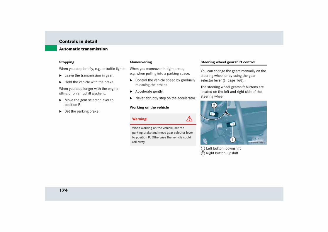
174
Controls in detail
Automatic transmission
Stopping
When you stop briefly, e.g. at traffic lights:
� Leave the transmission in gear.
� Hold the vehicle with the brake.
When you stop longer with the engine idling or on an uphill gradient:
� Move the gear selector lever to position P.
� Set the parking brake.
Maneuvering
When you maneuver in tight areas, e.g. when pulling into a parking space:
� Control the vehicle speed by gradually releasing the brakes.
� Accelerate gently.
� Never abruptly step on the accelerator.
Working on the vehicle
Steering wheel gearshift control
You can change the gears manually on the steering wheel or by using the gear selector lever (� page 168).
The steering wheel gearshift buttons are located on the left and right side of the steering wheel.
1 Left button: downshift2 Right button: upshift
Warning! G
When working on the vehicle, set the parking brake and move gear selector lever to position P. Otherwise the vehicle could roll away.
175
Controls in detail
Automatic transmission
Downshifting
� Press button 1 on the left side of the steering wheel.
The transmission shifts to the next low-er gear.
The current gear selector position ap-pears in the right multifunction display (� page 117).
The gear range (� page 170) is limited when you are not driving in the manual gearshift program mode M (� page 175).
Upshifting
� Press button 2 on the right side of the steering wheel.
The transmission shifts to the next higher gear.
The current gear selector position ap-pears in the right multifunction display (� page 117).
The gear range (� page 170) is extended when you are not driving in the manual gearshift program mode M (� page 175).
Manual gearshift program
In the manual gearshift program M you can change the gears manually on the steering wheel (� page 174) or by using the gear selector lever (� page 168).
Activating manual gearshift program
� Turn program mode selector switch 1 (� page 173) to the MAN setting.
The transmission switches to the manual program mode M. The letter M appears in the right multifunction dis-play and the lamp in program mode se-lector switch 3 (� page 176) comes on. Automatic shifting is switched off. The gear range is not limited.
iYou can change gears using the steer-ing wheel gearshift buttons indepen-dent of the currently selected gearshift program (C/MAN/S).
You cannot shift with the steering wheel gearshift buttons when the gear selector lever is in position P, N or R.
Warning! G
On slippery road surfaces, never downshift in order to obtain braking action. This could result in drive wheel slip and reduced vehicle control. Your vehicle’s ABS will not prevent this type of loss of control.
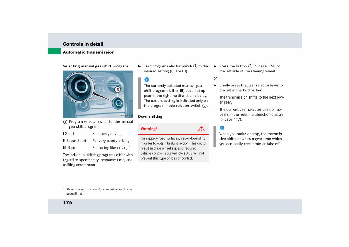
176
Controls in detail
Automatic transmission
Selecting manual gearshift program
3 Program selector switch for the manual gearshift program
I Sport For sporty driving
II Super Sport For very sporty driving
III Race For racing-like driving1
The individual shifting programs differ with regard to spontaneity, response time, and shifting smoothness.
� Turn program selector switch 3 to the desired setting (I, II or III).
Downshifting
� Press the button 1 (� page 174) on the left side of the steering wheel.
or
� Briefly press the gear selector lever to the left in the D- direction.
The transmission shifts to the next low-er gear.
The current gear selector position ap-pears in the right multifunction display (� page 117).
1 Please always drive carefully and obey applicable speed limits.
iThe currently selected manual gear-shift program (I, II or III) does not ap-pear in the right multifunction display. The current setting is indicated only on the program mode selector switch 3.
Warning! G
On slippery road surfaces, never downshift in order to obtain braking action. This could result in drive wheel slip and reduced vehicle control. Your vehicle’s ABS will not prevent this type of loss of control.
iWhen you brake or stop, the transmis-sion shifts down to a gear from which you can easily accelerate or take off.
177
Controls in detail
Automatic transmission
Upshifting � Press the button 2 (� page 174) on the right side of the steering wheel.
or
� Briefly press the gear selector lever to the right in the D+ direction.
The transmission shifts to the next higher gear.
The current gear selector position ap-pears in the right multifunction display (� page 117).
If the red gearshift indicator lamp > comes on in the speedometer display (� page 29), shift to the next higher gear. The fuel supply will otherwise be interrupt-ed to prevent the engine from overrevving.
Deactivating manual gearshift program
� Turn program mode selector switch 1 (� page 173) to the C or S setting.
The selected gearshift program ap-pears in the right multifunction display.
Emergency operation (Limp Home Mode)
If vehicle acceleration worsens or the transmission no longer shifts, the trans-mission is most likely operating in limp home (emergency operation) mode. In this mode only second gear and reverse gear can be activated.
� Stop the vehicle.
� Move gear selector lever to P.
� Turn off the engine.
� Wait at least ten seconds before restarting.
� Restart the engine.
� Move gear selector lever to position D (for second gear) or R.
� Have the transmission checked at an authorized Mercedes-Benz Center as soon as possible.
!In the manual program mode M, the transmission will not upshift, even if the engine has reached its overrevving range. Shift up to the next gear before the engine has reached its overrevving range. Make absolutely certain that the engine speed does not reach the red marking on the tachometer (� page 28). Otherwise the engine could be damaged which is not covered by the Mercedes-Benz Limited Warranty.
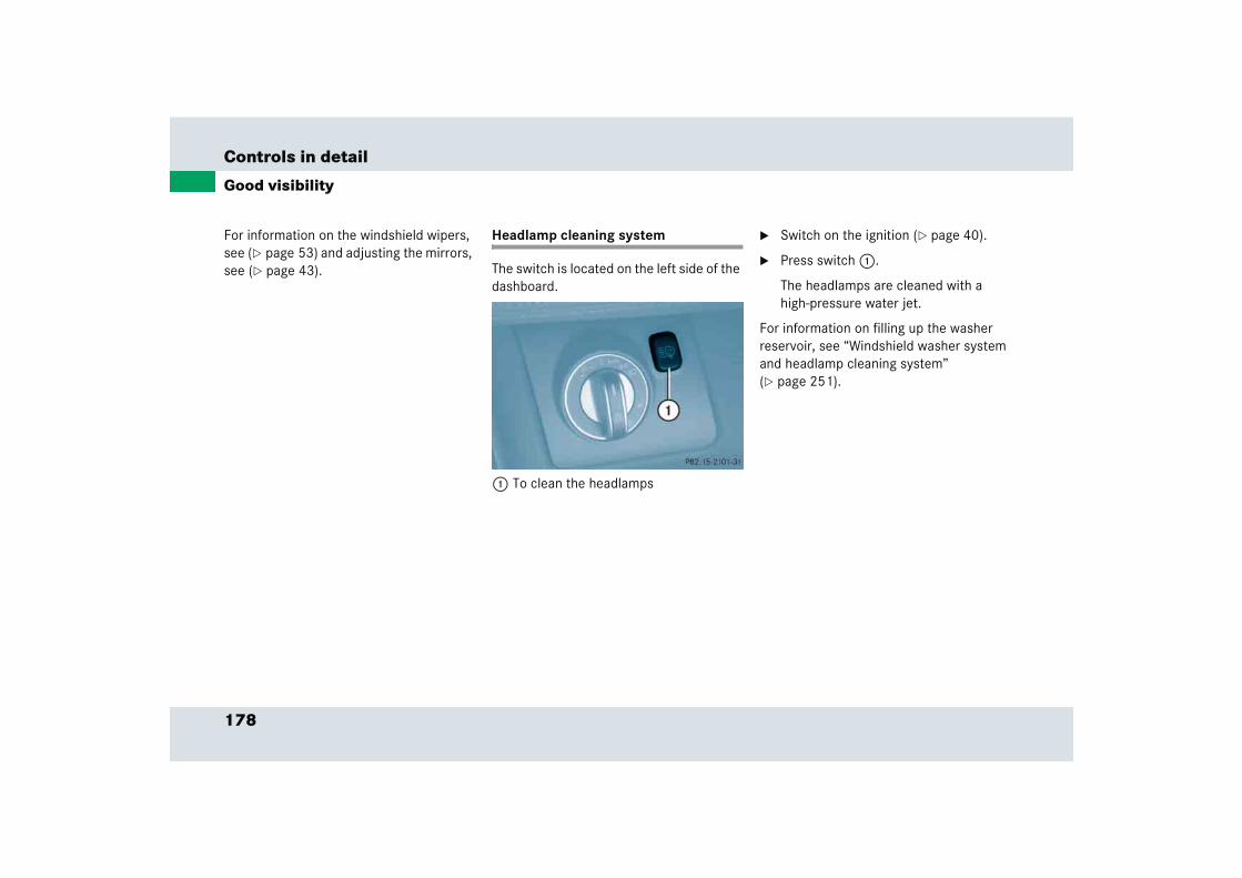
178
Controls in detail
Good visibility
For information on the windshield wipers, see (� page 53) and adjusting the mirrors, see (� page 43).
Headlamp cleaning system
The switch is located on the left side of the dashboard.
1 To clean the headlamps
� Switch on the ignition (� page 40).
� Press switch 1.
The headlamps are cleaned with a high-pressure water jet.
For information on filling up the washer reservoir, see “Windshield washer system and headlamp cleaning system” (� page 251).
179
Controls in detail
Good visibility
Rear view mirrors
For more information on setting the rear view mirrors, see “Mirrors” (� page 43).
Auto-dimming mirror
The reflection brightness of the interior rear view mirror will respond automatically to glare when
� the ignition is switched on
and
� incoming light from headlamps falls on the sensor in the interior rear view mirror.
The rear view mirror will not react if
� reverse gear R is engaged
� the interior lighting is turned on
Warning! G
The auto-dimming function does not react if incoming light is not aimed directly at sen-sors in the interior rear view mirror.
Glare can endanger you and others.
Warning! G
In the case of an accident liquid electrolyte may escape from the mirror housing if the mirror glass breaks.
Electrolyte has an irritating effect. Do not allow the liquid to come into contact with eyes, skin, clothing, or respiratory system. In case it does, immediately flush affected area with water, and seek medical help if necessary.
!Electrolyte drops coming into contact with the vehicle paint finish can be completely removed only while in the liquid state and by applying plenty of water.
Warning! G
Exercise care when using the passen-ger-side exterior rear view mirror. The mirror surface is convex (outwardly curved surface for a wider field of view). Objects in mirror are closer than they appear. Check your interior rear view mirror or glance over your shoulder before changing lanes.
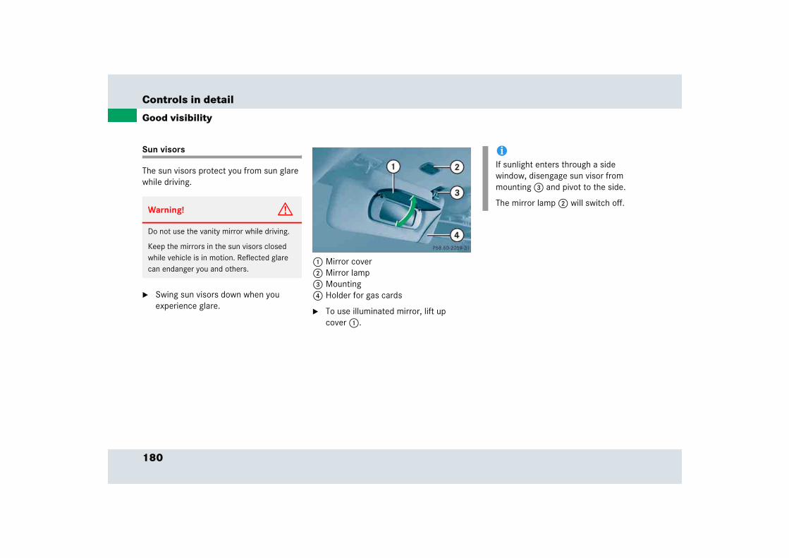
180
Controls in detail
Good visibility
Sun visors
The sun visors protect you from sun glare while driving.
� Swing sun visors down when you experience glare.
1 Mirror cover2 Mirror lamp3 Mounting4 Holder for gas cards
� To use illuminated mirror, lift up cover 1.
Warning! G
Do not use the vanity mirror while driving.
Keep the mirrors in the sun visors closed while vehicle is in motion. Reflected glare can endanger you and others.
iIf sunlight enters through a side window, disengage sun visor from mounting 3 and pivot to the side.
The mirror lamp 2 will switch off.
181
Controls in detail
Good visibility
Rear window defroster
The rear window defroster uses a large amount of power. To keep the battery drain to a minimum, switch off the defroster as soon as the rear window is clear. The defroster is automatically deactivated after approximately 6 to 17 minutes of operation depending on the outside temperature.
Activating
� Press button F in the climate control panel (� page 184).
The indicator lamp on the button comes on.
Deactivating
� Press button F again.
The indicator lamp on the button goes out.
Warning! G
Any accumulation of snow and ice should be removed from the rear window before driving. Visibility could otherwise be impaired, endangering you and others.
!If the rear window defroster switches off too soon and the indicator lamp starts flashing, this means that too many electrical consumers are operating simultaneously and there is insufficient voltage in the battery. The system responds automatically by deactivating the rear window defroster.
As soon as the battery has sufficient voltage, the rear window defroster automatically turns itself back on.
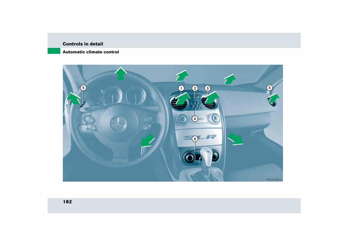
182
Controls in detail
Automatic climate control
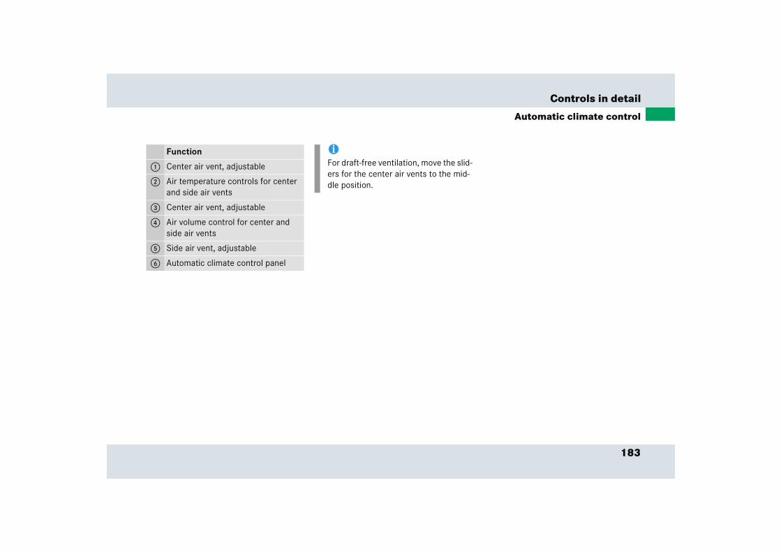
183
Controls in detail
Automatic climate control
Function
1 Center air vent, adjustable
2 Air temperature controls for center and side air vents
3 Center air vent, adjustable
4 Air volume control for center and side air vents
5 Side air vent, adjustable
6 Automatic climate control panel
iFor draft-free ventilation, move the slid-ers for the center air vents to the mid-dle position.
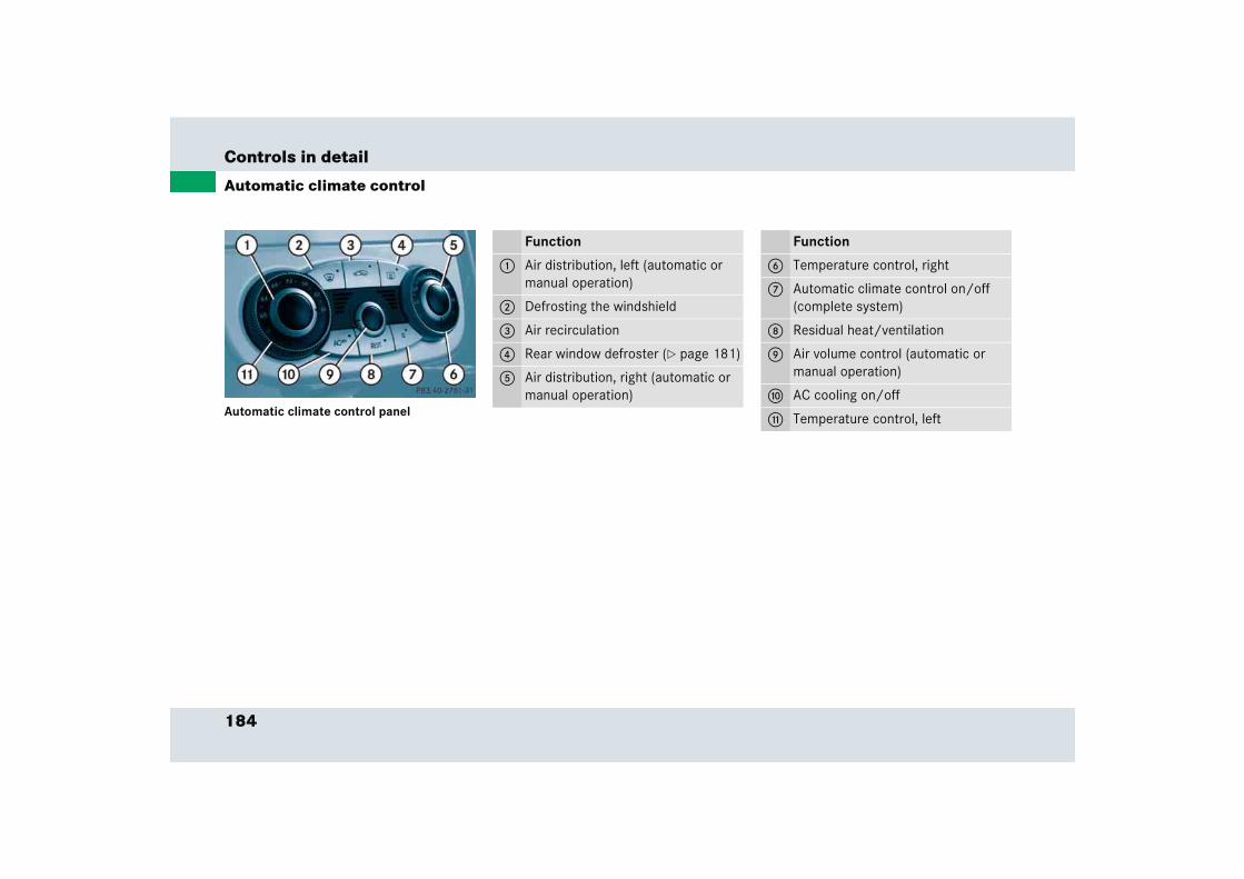
184
Controls in detail
Automatic climate control
Automatic climate control panel
Function
1 Air distribution, left (automatic or manual operation)
2 Defrosting the windshield
3 Air recirculation
4 Rear window defroster (� page 181)
5 Air distribution, right (automatic or manual operation)
Function
6 Temperature control, right
7 Automatic climate control on/off (complete system)
8 Residual heat/ventilation
9 Air volume control (automatic or manual operation)
a AC cooling on/off
b Temperature control, left
185
Controls in detail
Automatic climate control
The automatic climate control is operation-al whenever the engine is running. You can operate the climate control system in ei-ther the automatic or manual mode. The system cools or heats the interior depend-ing on the selected interior temperature and the current outside temperature.
Nearly all dust particles, pollutants and odors are filtered out before outside air en-ters the passenger compartment through the air distribution system.
Adjusting the temperature
Use temperature controls 6 and b to separately adjust the air temperature on each side of the passenger compartment. You should raise or lower the temperature setting in small increments, preferably starting at 72°F (22°C).
Increasing
� Turn the outer adjustment ring slightly to the right.
The automatic climate control system will correspondingly adjust the interior air temperature.
Warning! G
When operating the automatic climate con-trol, the air that enters the passenger com-partment through the air vents in the footwell can be very hot or very cold (de-pending on the set temperature). This may cause burns or frostbite on unprotected skin in the immediate area of the air vents. Al-ways keep sufficient distance between un-protected parts of the body and the footwell air vents. If necessary change the air flow using the air distribution controls to direct the air away from the footwell air vents (� page 187).
Warning! G
Follow the recommended settings for heat-ing and cooling given on the following pag-es. Otherwise the windows could fog up, impairing visibility and endangering you and others.
iIf the vehicle interior is hot, ventilate the interior before driving off.
Keep the air intake grille in front of the windshield free of snow and debris.
iWhen operating the climate control system in automatic mode, you will only rarely need to adjust the tempera-ture, air volume and air distribution.
186
Controls in detail
Automatic climate control
Decreasing
� Turn the outer adjustment ring slightly to the left.
The automatic climate control system will correspondingly adjust the interior air temperature.
Adjusting the temperature for the center and side air vents
When outside temperatures are low, you can manually raise the air temperature for the center and side air vents. The controls 2 are located between the cen-ter air vents (� page 182).
Turning on warm air
� Press the left button (red).
The indicator lamp on the button comes on. Warm air will enter from the center and side air vents.
Turning off warm air
� Press the left button (red).
The indicator lamp on the button goes out. The air from the outlets will return to the temperature set in the system.
Turning on cooler air
� Press the right button (blue).
The indicator lamp on the button comes on. Cooler air will enter from the center and side air vents.
Turning off cooler air
� Press the right button (blue).
The indicator lamp on the button goes out. The air from the outlets will return to the temperature set in the system.
Adjusting air volume
Use air volume control knob 9 (� page 184) for both automatic and man-ual air volume adjustment.
Adjusting manually
� Press the control knob.
The U light on the control knob goes out. You can now select one of nine air volume settings.
Adjusting automatically
� Press the control knob.
The U light on the control knob comes on. The airflow is adjusted auto-matically.
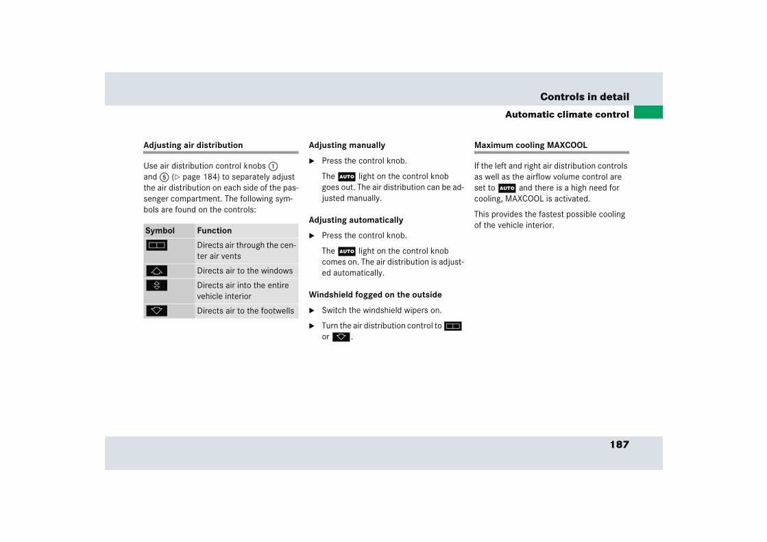
187
Controls in detail
Automatic climate control
Adjusting air distribution
Use air distribution control knobs 1 and 5 (� page 184) to separately adjust the air distribution on each side of the pas-senger compartment. The following sym-bols are found on the controls:
Adjusting manually
� Press the control knob.
The U light on the control knob goes out. The air distribution can be ad-justed manually.
Adjusting automatically
� Press the control knob.
The U light on the control knob comes on. The air distribution is adjust-ed automatically.
Windshield fogged on the outside
� Switch the windshield wipers on.
� Turn the air distribution control to h or k.
Maximum cooling MAXCOOL
If the left and right air distribution controls as well as the airflow volume control are set to U and there is a high need for cooling, MAXCOOL is activated.
This provides the fastest possible cooling of the vehicle interior.
Symbol Function
h Directs air through the cen-ter air vents
j Directs air to the windows
V Directs air into the entire vehicle interior
k Directs air to the footwells
188
Controls in detail
Automatic climate control
Defrosting the windshield
Activating
� Press button P (� page 184).
The indicator lamp on the button comes on.
Deactivating
� Press button P (� page 184).
The indicator lamp on the button goes out. Defrosting is turned off.
Air recirculation mode
Switch to air recirculation mode to prevent unpleasant odors from entering the vehicle from the outside. This setting cuts off the intake of outside air and recirculates the air in the passenger compartment.
Activating
� Press button , (� page 184).
The indicator lamp on the button comes on.
iThese settings should only be selected for a short time.
Warning! G
When the outside temperature is below 41°F (5°C), only switch to air recirculation mode for short periods to prevent window fogging.
Warning! G
Never operate the windows if there is the possibility of anyone being harmed by the closing procedure.
In the event that the procedure causes po-tential danger, the closing of the windows can be immediately halted by releasing the , button or by pressing or pulling the re-spective window switch.

189
Controls in detail
Automatic climate control
Deactivating
� Press button , (� page 184).
The indicator lamp on the button goes out.
The air recirculation mode is deactivated automatically
� after five minutes if the outside temper-ature is below approximately 41°F (5°C)
� after five minutes if the air conditioner is turned off
� after 30 minutes if the outside temper-ature is above approximately 41°F (5°C)
At outside temperatures above 79°F (26°C) the system will not automatically switch back to outside air. A quantity of outside air is added after approximately 30 minutes.
iIf you keep button , pressed, the windows will close.
The air recirculation mode is activated automatically
� at high outside temperatures
� if the concentration of carbon mon-oxide and nitrogen oxide in the out-side air increases, for example in a tunnel
If you have turned off the air condition-er (� page 192) or the outside temperature is below 41°F (5°C), the air recirculation mode will not switch on automatically.
iIf you keep button , pressed, the windows will return to their previous position.
190
Controls in detail
Automatic climate control
Residual heat and ventilation
With the engine switched off, it is possible to continue to heat or ventilate the interior for up to 30 minutes. This feature makes use of the residual heat produced by the engine.
Activating
� Turn the SmartKey in the starter switch to position 1 or 0 or remove it from the starter switch.
� Press button T (� page 184).
The indicator lamp on button T comes on.
Deactivating
� Press button T (� page 184).
The indicator lamp on button T goes out.
The residual heat is automatically turned off:
� when the ignition is switched on
� after about 30 minutes
� if the battery voltage drops
iHow long the system will provide heat-ing depends on the coolant tempera-ture and the temperature set by the operator. The blower will run at speed setting 1 regardless of the air distribu-tion control setting.
191
Controls in detail
Automatic climate control
Deactivating the automatic climate control system
Deactivating
It is possible to completely deactivate the automatic climate control system.
� Press button M (� page 184).
The indicator lamp on button M comes on.
Reactivating
There are several ways to reactivate the automatic climate control system:
� Press any button on the automatic cli-mate control panel (� page 184).
The indicator lamp on button M switches off.
or
� Turn one of the control knobs on the automatic climate control.
The indicator lamp on button M switches off.
iWhen the air conditioning is switched off, the outside air supply and circula-tion are also switched off. Only choose this setting for a short time. Otherwise the windows could fog up. i
Under certain circumstances, e.g. when the fuel system is too hot and needs to be cooled, the cooling switch-es on again automatically. The red lamp on the ± button the automatic cli-mate control panel flashes.
After cooling the fuel system sufficient-ly, the air conditioning switches off again and the red lamp stops flashing.
192
Controls in detail
Automatic climate control
Air conditioning
The air conditioning is operational while the engine is running and cools the interior air to the temperature set by the operator.
Deactivating
It is possible to deactivate the air condi-tioning (cooling) function of the automatic climate control system. The air in the vehi-cle will then no longer be cooled or dehu-midified.
� Press ± button (� page 184).
The indicator lamp on the ± button comes on.
Activating
Moist air can fog up the windows. You can dehumidify the air with the air condition-ing.
� Press ± button again (� page 184).
The indicator lamp on the ± button goes out.
The air conditioning uses the refrigerant R134A. This refrigerant is free of CFCs which are harmful to the ozone layer.
iCondensation may drip out from under-neath the vehicle. This is normal and not an indication of a malfunction.
iUnder certain circumstances, e.g. when the fuel system is too hot and needs to be cooled, the cooling switch-es on again automatically. The red lamp on the ± button the automatic cli-mate control panel flashes.
After cooling the fuel system sufficient-ly, the air conditioning switches off again and the red lamp stops flashing.
!If you press the ± button on the au-tomatic climate control panel and it starts to flash, this indicates that the air conditioning is losing refrigerant. The compressor has turned off. The air conditioning cannot be turned on again.
Have the air conditioning checked at the nearest authorized Mercedes-Benz Center.

193
Controls in detail
Power windows
� Power windowsOpening and closing the windows
The windows are opened and closed elec-trically. The switches for the windows are located on the door sill on the driver’s side (� page 34). The switch for the passenger side is located on the door sill on the pas-senger side.
1 Left window 2 Right window
� Switch on the ignition (� page 40).
Warning! G
When closing the windows, make sure there is no danger of anyone being harmed by the closing procedure.
The closing of the windows can be immedi-ately halted by releasing the switch or, if switch was pulled past the resistance point and released, by either pressing or pulling the respective switch.
If the window encounters an obstruction that blocks its path in a circumstance where you pulled the switch past the resistance point and released it to close the window, the automatic reversal function will stop the window and open it slightly.
If the window encounters an obstruction that blocks its path in a circumstance where you are closing the window by pulling and holding the switch, or by pressing and hold-ing button ‹ on the SmartKey, the auto-matic reversal function will not operate.
When leaving the vehicle, always remove the SmartKey from starter switch, take it with you, and lock the vehicle. Do not leave children unattended in the vehicle, or with access to an unlocked vehicle. Unsuper-vised use of vehicle equipment can cause an accident and/or serious personal injury.

194
Controls in detail
Power windows
Opening the windows
� Press switch 1 or 2 to the resistance point.
The corresponding window will move downwards until you release the switch.
Closing the windows
� Pull switch 1 or 2 to the resistance point.
The corresponding window will move upwards until you release the switch.
Fully opening the windows (Express-open)
� Press switch 1 or 2 past the resis-tance point and release.
The corresponding window opens com-pletely.
Fully closing the windows (Express-close)
� Pull switch 1 to 4 past the resistance point and release.
The corresponding window closes completely.
Warning! G
If you pull and hold the switch up when closing the window, and upward movement of the window is blocked by some obstruc-tion including but not limited to arms, hands, fingers, etc., the automatic reversal will not operate.
!If the upward movement of the window is blocked during the closing procedure, the window will stop and open slightly.
Remove the obstruction, pull the switch again past the resistance point and release.
If the window still does not close when there is no obstruction, then pull and hold the switch again. The window will then close without the obstruction sen-sor function.
Warning! G
Driver’s door only:If within five seconds you again pull the switch past the resistance point and release, the automatic reversal will not function.
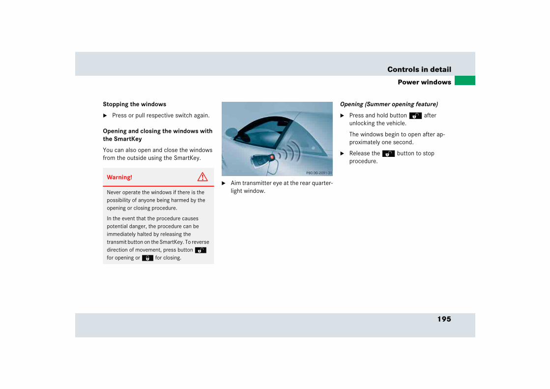
195
Controls in detail
Power windows
Stopping the windows
� Press or pull respective switch again.
Opening and closing the windows with the SmartKey
You can also open and close the windows from the outside using the SmartKey.
� Aim transmitter eye at the rear quarter-light window.
Opening (Summer opening feature)
� Press and hold button Œ after unlocking the vehicle.
The windows begin to open after ap-proximately one second.
� Release the Œ button to stop procedure.
Warning! G
Never operate the windows if there is the possibility of anyone being harmed by the opening or closing procedure.
In the event that the procedure causes potential danger, the procedure can be immediately halted by releasing the transmit button on the SmartKey. To reverse direction of movement, press button Œ
for opening or ‹ for closing.
196
Controls in detail
Power windows
Closing (Convenience feature)
� Press and hold button ‹ after locking the vehicle.
The windows begin to close after ap-proximately one second.
� Release the ‹ button to stop procedure.
Make sure all windows are properly closed before leaving the vehicle.
Synchronizing power windows
The power windows must be resynchronized each time
� after the battery has been disconnected.
� if the power windows cannot be fully opened (Express-open) or closed (Express-close).
� Switch on the ignition (� page 40).
� Pull the power window switches until the windows are closed.
Hold the switches for approximately one second.
The power windows are synchronized.
197
Controls in detail
Driving systems
� Driving systemsThe driving system of your vehicle is described on the following pages:
� Cruise control, with which the vehicle can maintain a preset speed
For information on the BAS, ABS and ESP driving systems, (� page 79).
Cruise control
Cruise control automatically maintains the speed you set for your vehicle.
Use of cruise control is recommended for driving at a constant speed for extended periods of time. You can set or resume cruise control at any speed over 20 mph (30 km/h).
The cruise control function is operated by means of the cruise control lever.
The cruise control lever is the uppermost lever on the left-hand side of the steering column (� page 30).
Warning! G
Cruise control is a convenience system de-signed to assist the driver during vehicle op-eration. The driver is and must remain at all times responsible for the vehicle speed and for safe brake operation.
Only use cruise control if the road, traffic and weather conditions make it advisable to travel at a steady speed.
� The use of cruise control can be danger-ous on winding roads or in heavy traffic because conditions do not allow safe driving at a steady speed.
� The use of cruise control can be danger-ous on slippery roads. Rapid changes in tire traction can result in wheel spin and loss of control.
� Deactivate cruise control when driving in fog.
The “Resume” function should only be oper-ated if the driver is fully aware of the previ-ously set speed and wishes to resume this particular preset speed.

198
Controls in detail
Driving systems
1 Sets current or higher speed2 Sets current or lower speed3 Cancels cruise control4 Resumes at last set speed
Setting current speed
� Accelerate or decelerate to the desired speed.
� Briefly lift 1 or depress 2 the cruise control lever.
The current speed is set.
� Remove your foot from the accelerator pedal.
Cruise control is activated.
Canceling cruise control
There are several ways to cancel cruise control:
� Step on the brake pedal.
Cruise control is canceled. The last speed set is stored for later use.
or
� Briefly push the cruise control lever to position 3.
Cruise control is canceled. The last speed set is stored for later use.
The cruise control is automatically can-celled, when
� ESP works to stabilize the vehicle
� you move the gear selector lever to position N
iOn uphill or downhill grades, cruise control may not be able to maintain the set speed. Once the grade eases, the set speed will be resumed.
!However, the gear selector lever should not be moved to position N while driving, except to coast when the vehicle is in danger of skidding (e.g. on icy roads).
iThe last stored speed is canceled when you turn off the engine.
199
Controls in detail
Driving systems
Setting a higher speed
� Lift cruise control lever to position 1 and hold it up until the desired speed is reached.
� Release cruise control lever.
The new speed is set.
Setting a lower speed
� Depress cruise control lever to position 2 and hold it down until the desired speed is reached.
� Release cruise control lever.
The new speed is set.
Fine adjustment in 1 mph (Canada: 1 km/h) increments
Faster
� Briefly tip cruise control lever in direction of arrow 1.
Slower
� Briefly tip cruise control lever in direction of arrow 2.
Setting to last stored speed (“Resume” function)
� Briefly push cruise control lever to position 4.
The cruise control resumes the last set speed.
� Remove your foot from the accelerator pedal.
iDepressing the accelerator pedal does not deactivate cruise control. After brief acceleration (e.g. for passing), cruise control will resume the last speed set.
iWhen you use the cruise control lever to decelerate, the transmission will automatically downshift if the engine’s braking power does not brake the vehicle sufficiently.
Warning! G
The speed stored in memory should only be set again if prevailing road conditions per-mit. Possible acceleration or deceleration differences arising from returning to preset speed could cause an accident and/or seri-ous injury to you and others.

200
Controls in detail
Useful features
Map pocket in passenger footwell Storage compartments Armrest storage compartment
� Reach into the recess and lift armrest.
The armrest opens automatically.
Warning! G
Do not place heavy or fragile objects, or ob-jects having sharp edges, in the map pocket.
In an accident, during hard braking or sud-den maneuvers, they could be thrown around inside the vehicle, and cause injury to vehicle occupants.
Warning! G
To help avoid personal injury during a colli-sion or sudden maneuver, exercise care when stowing objects in the vehicle. Put lug-gage or cargo in the trunk. Do not pile lug-gage or cargo higher than the seat backs. Do not place anything on the shelf below the rear window.
Luggage nets cannot secure hard or heavy objects.
Keep compartment lids closed. This will help to prevent stored objects from being thrown about and injuring vehicle occupants during an accident.

201
Controls in detail
Useful features
Center storage compartment
1 Release button2 Cover
� Press release button 1.
Cover 2 opens automatically.
The telephone is installed in the cover of the storage compartment.
Rear storage compartment
1 Release button2 Cover
� Press release button 1.
Cover 2 opens automatically.
Parcel net in trunk
There is a net available in the trunk to se-cure loads:
� Pull the trunk floor net from the trunk back wall towards the front over the luggage.
� Hang the hooks of the net on the eyes on the trunk floor.
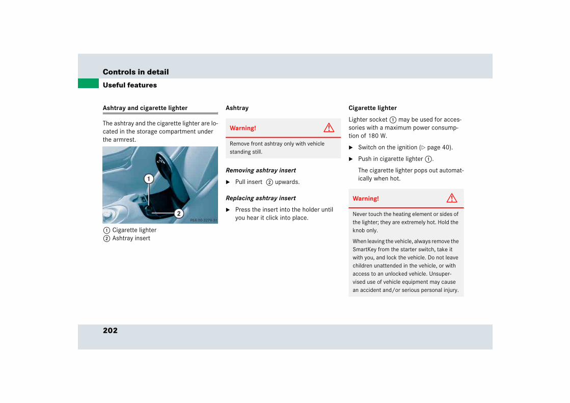
202
Controls in detail
Useful features
Ashtray and cigarette lighter
The ashtray and the cigarette lighter are lo-cated in the storage compartment under the armrest.
1 Cigarette lighter2 Ashtray insert
Ashtray
Removing ashtray insert
� Pull insert 2 upwards.
Replacing ashtray insert
� Press the insert into the holder until you hear it click into place.
Cigarette lighter
Lighter socket 1 may be used for acces-sories with a maximum power consump-tion of 180 W.
� Switch on the ignition (� page 40).
� Push in cigarette lighter 1.
The cigarette lighter pops out automat-ically when hot.
Warning! G
Remove front ashtray only with vehicle standing still.
Warning! G
Never touch the heating element or sides of the lighter; they are extremely hot. Hold the knob only.
When leaving the vehicle, always remove the SmartKey from the starter switch, take it with you, and lock the vehicle. Do not leave children unattended in the vehicle, or with access to an unlocked vehicle. Unsuper-vised use of vehicle equipment may cause an accident and/or serious personal injury.
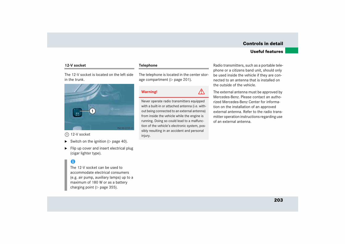
203
Controls in detail
Useful features
12-V socket
The 12-V socket is located on the left side in the trunk.
1 12-V socket
� Switch on the ignition (� page 40).
� Flip up cover and insert electrical plug (cigar lighter type).
Telephone
The telephone is located in the center stor-age compartment (� page 201).
Radio transmitters, such as a portable tele-phone or a citizens band unit, should only be used inside the vehicle if they are con-nected to an antenna that is installed on the outside of the vehicle.
The external antenna must be approved by Mercedes-Benz. Please contact an autho-rized Mercedes-Benz Center for informa-tion on the installation of an approved external antenna. Refer to the radio trans-mitter operation instructions regarding use of an external antenna.
iThe 12-V socket can be used to accommodate electrical consumers (e.g. air pump, auxiliary lamps) up to a maximum of 180 W or as a battery charging point (� page 355).
Warning! G
Never operate radio transmitters equipped with a built-in or attached antenna (i.e. with-out being connected to an external antenna) from inside the vehicle while the engine is running. Doing so could lead to a malfunc-tion of the vehicle’s electronic system, pos-sibly resulting in an accident and personal injury.

204
Controls in detail
Useful features
You can take and place telephone calls us-ing the í and ì buttons on the steering wheel. To carry out other tele-phone functions, use the control system (� page 138).
See separate instruction manual for in-structions on how to operate the tele-phone.
Removing the cellular phone from the cellular phone cradle
1 Release button2 Remove the cellular phone
� Press the release button 1 and re-move the cellular phone in direction of arrow 2 from the cellular phone cradle.
Warning! G
Please do not forget that your primary re-sponsibility is to drive the vehicle. A driver’s attention to the road must always be his/her primary focus when driving. For your safety and the safety of others, we rec-ommend that you pull over to a safe location and stop before placing or taking a tele-phone call.
If you choose to use the telephone1 while driving, please use the hands-free device and only use the telephone when road, weather and traffic conditions permit. Some jurisdictions prohibit the driver from using a cellular telephone while driving a vehicle.
Bear in mind that at a speed of just 30 mph (approximately 50 km/h), your vehicle is covering a distance of 44 feet (approximately 14 m) every second.
1 Observe all legal requirements.
iFor additional information on operating the telephone using the audio system head unit, see “Telephone operation” (� page 160).
iStandard Mercedes-Benz cellular phone design shown, SLR phone de-sign may vary.
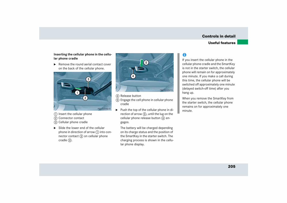
205
Controls in detail
Useful features
Inserting the cellular phone in the cellu-lar phone cradle
� Remove the round aerial contact cover on the back of the cellular phone.
1 Insert the cellular phone2 Connector contact3 Cellular phone cradle
� Slide the lower end of the cellular phone in direction of arrow 1 into con-nector contact 2 on cellular phone cradle 3.
4 Release button5 Engage the cell phone in cellular phone
cradle
� Push the top of the cellular phone in di-rection of arrow 5, until the lug on the cellular phone release button 4 en-gages.
The battery will be charged depending on its charge status and the position of the SmartKey in the starter switch. The charging process is shown in the cellu-lar phone display.
iIf you insert the cellular phone in the cellular phone cradle and the SmartKey is not in the starter switch, the cellular phone will remain on for approximately one minute. If you make a call during this time, the cellular phone will be switched off approximately one minute (delayed switch-off time) after you hang up.
When you remove the SmartKey from the starter switch, the cellular phone remains on for approximately one minute.
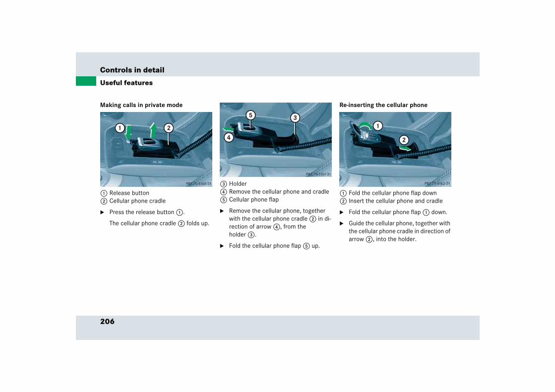
206
Controls in detail
Useful features
Making calls in private mode
1 Release button2 Cellular phone cradle
� Press the release button 1.
The cellular phone cradle 2 folds up.
3 Holder4 Remove the cellular phone and cradle5 Cellular phone flap
� Remove the cellular phone, together with the cellular phone cradle 2 in di-rection of arrow 4, from the holder 3.
� Fold the cellular phone flap 5 up.
Re-inserting the cellular phone
1 Fold the cellular phone flap down2 Insert the cellular phone and cradle
� Fold the cellular phone flap 1 down.
� Guide the cellular phone, together with the cellular phone cradle in direction of arrow 2, into the holder.

207
Controls in detail
Useful features
3 Engage cellular phone cradle
� Push the top of the cellular phone in di-rection of arrow 3, until the cellular phone cradle engages in the holder.
Making calls in hands-free mode
� Open the cellular phone flap.
� Either accept the call or dial the desired number.
� Close the cellular phone flap.
Hands-free mode is selected.
If you wish to change back to private mode:
� Open the cellular phone flap.
� Remove the cellular phone from the holder (� page 206).
Tele Aid
!To prevent any damage, the cellular phone flap must be folded down before closing the telephone compartment.
iFor additional information on operating the telephone using the audio system head unit, refer to “Telephone opera-tion” (� page 160) in chapter “Audio system”.
For additional information on operating the telephone using the multifunction steering wheel, refer to “Control sys-tem” (� page 138).
!The initial activation of the Tele Aid sys-tem may only be performed by com-pleting the subscriber agreement and placing an acquaintance call using the ¡ button. Failure to complete either of these steps will result in a system that is not activated.
If you have any questions regarding ac-tivation, please call the Response Center at 1-800-756-9018 (in the USA) or 1-888-881-6611 (in Canada).

208
Controls in detail
Useful features
The Tele Aid system
(Telematic Alarm Identification on De-mand)
The Tele Aid system consists of three types of response:
� automatic and manual emergency
� Roadside assistance
� information
The Tele Aid system is operational provid-ing that the vehicle’s battery is charged, properly connected, not damaged and cel-lular and GPS coverage is available.
The speaker volume of a Tele Aid call can be adjusted when using the volume control on the multifunction steering wheel. To raise, press button æ and to lower, press button ç.
� To activate, press the SOS button, the Roadside Assistance button • or the Information button ¡, depend-ing on the type of response required.
Shortly after the completion of your Tele Aid acquaintance call, you will receive a user ID and password. By visiting www.mbusa.com and selecting “Tele Aid” (USA only), you will have access to account information, remote door unlock, and more.
System self-check
Initially, after switching on the ignition, malfunctions are detected and indicated (the indicator lamps in the SOS button, the Roadside Assistance button • and the Information button ¡ stay on longer than ten seconds or do not come on). The message Tele Aid – Drive to workshop! appears for approximately ten seconds in the multifunction display.
iThe SOS button is located above the in-side rear view mirror.
The Roadside Assistance button • and the Information button ¡ are located in the center storage compart-ment (� page 201).
!The Tele Aid system utilizes the cellular network for communication and the GPS (Global Positioning System) satel-lites for vehicle location. If either of these signals are unavailable, the Tele Aid system may not function and if this occurs, assistance must be summoned by other means.
209
Controls in detail
Useful features
Emergency calls
An emergency call is initiated automatically following an accident in which the emergency tensioning devices (ETDs) or airbags have deployed.
An emergency call can also be initiated manually by opening the cover next to the inside rear view mirror labeled SOS, then briefly pressing the button located under the cover.
For more information, see “Initiating an emergency call manually” (� page 210).
Once the emergency call is in progress, the indicator lamp in the SOS button will begin to flash. The message Connecting call appears in the multifunction display. When the connection is established, the mes-sage Call connected appears in the multi-function display. All information relevant to the emergency, such as the location of the vehicle (determined by the GPS satellite lo-cation system), vehicle model, identifica-tion number and color are generated.
A voice connection between the Response Center and the occupants of the vehicle will be established automatically soon af-ter the emergency call has been initiated. The Response Center will attempt to deter-mine more precisely the nature of the acci-dent provided they can speak to an occupant of the vehicle.
Warning! G
If the indicator lamps in the SOS button, in the Roadside Assistance button, and/or in the Information button do not come on dur-ing the system self-check, or if any of these indicators remain illuminated continuously in red and/or the message Tele Aid - Drive to workshop! is displayed in the multifunction display after the system self-check, a malfunction in the system has been detected.
If a malfunction is indicated as outlined above, the system may not operate as ex-pected. Have the system checked at the nearest Mercedes-Benz Center as soon as possible.

210
Controls in detail
Useful features
The Tele Aid system is available if
� it has been activated and is operation-al. Activation requires a subscription for monitoring services, connection and cellular air time
� the relevant cellular phone network and GPS signals are available and pass the information on to the Response Center
Initiating an emergency call manually
1 Cover2 SOS button
� Briefly press on cover 1.
The cover will open.
� Press SOS button 2 briefly.
The indicator lamp in SOS button 2 will flash until the emergency call is concluded.
� Wait for a voice connection to the Re-sponse Center.
� Close cover 1 after the emergency call is concluded.
iLocation of the vehicle on a map is only possible if the vehicle is able to receive signals from the GPS satellite network and pass the information on to the Re-sponse Center.
Warning! G
If the indicator lamp in the SOS button is flashing continuously and there was no voice connection to the Response Center established, then the Tele Aid system could not initiate an emergency call (e.g. the rele-vant cellular phone network is not available). The message Call failed appears in the multifunction display for approximately ten seconds.
Should this occur, assistance must be sum-moned by other means.
211
Controls in detail
Useful features
Roadside Assistance button •
The Roadside Assistance button • is located below the center armrest cover.
� Press and hold the button (for longer than two seconds)
A call to a Mercedes-Benz Roadside Assistance dispatcher will be initiated. The button will flash while the call is in progress. The message Connecting call will appear in the multifunction display.
When the connection is established, the message Call connected appears in the multifunction display. The Tele Aid system will transmit data generating the vehicle identification number, model, color and lo-cation (subject to availability of cellular and GPS signals).
A voice connection between the Roadside Assistance dispatcher and the occupants of the vehicle will be established.
� Describe the nature of the need for as-sistance.
The Mercedes-Benz Roadside Assistance dispatcher will either dispatch a qualified Mercedes-Benz technician or arrange to tow your vehicle to the nearest authorized Mercedes-Benz Center. For services such as labor and/or towing, charges may ap-ply. Refer to the Roadside Assistance Man-ual for more information.
These programs are only available in the USA:
� Sign and Drive services: Services such as jump start, a few gallons of fuel or the replacement of a flat tire are ob-tainable.
Warning! G
If you feel at any way in jeopardy when in the vehicle (e.g. smoke or fire in the vehicle, ve-hicle in a dangerous road location), please do not wait for voice contact after you have pressed the emergency button. Carefully leave the vehicle and move to a safe loca-tion. The Response Center will automatically contact local emergency officials with the vehicle’s approximate location if they re-ceive an automatic SOS signal and cannot make voice contact with the vehicle occu-pants.
212
Controls in detail
Useful features
Information button ¡
The Information button ¡ is located be-low the center armrest cover.
� Press and hold the button (for longer than two seconds).
A call to the Customer Assistance Cen-ter will be initiated. The button will flash while the call is in progress. The message Connecting call will appear in the multifunction display.
When the connection is established, the message Call connected appears in the multifunction display. The Tele Aid system will transmit data generating the vehicle identification number, model, color and lo-cation (subject to availability of cellular and GPS signals).
A voice connection between the Customer Assistance Center representative and the occupants of the vehicle will be estab-lished. Information regarding the operation of your vehicle, the nearest Mercedes-Benz Center or Mercedes-Benz USA products and services is available to you.
For more details concerning the Tele Aid system, please visit www.mbusa.com and use your ID and password (sent to you sep-arately) to learn more (USA only).
iThe indicator lamp in the Roadside Assistance button • remains illumi-nated in red for approximately ten sec-onds during the system self-check after switching on the ignition (together with the SOS button and the Information button ¡).
See system self-check (� page 208) if the indicator lamp does not come on in red or stays on longer than approxi-mately ten seconds.
If the indicator lamp in the Roadside Assistance button • is illuminated continuously and there was no voice connection to the Response Center es-tablished, then the Tele Aid system could not initiate a Roadside Assis-tance call (e.g. the relevant cellular phone network is not available). The message Call failed appears in the multifunction display.
Roadside Assistance calls can be ter-minated using the ì button on the multifunction steering wheel.

213
Controls in detail
Useful features
Upgrade scenario
An emergency call is possible even if other services are active.
iThe indicator lamp in the Information button ¡ remains illuminated in red for approximately ten seconds during the system self-check after switching on the ignition (together with the SOS button and the Roadside Assistance button •).
See system self-check (� page 208) if the indicator lamp does not come on in red or stays on longer than approxi-mately ten seconds.
If the indicator lamp in the Information button ¡ is illuminated continuous-ly and no voice connection to the Re-sponse Center was established, then the Tele Aid system could not initiate an Information call (e.g. the relevant cellular phone network is not avail-able). The message Call failed ap-pears in the multifunction display.
Information calls can be terminated us-ing the ì button on the multifunc-tion steering wheel.
!If the indicator lamps do not start flash-ing after pressing one of the buttons or remain illuminated (in red) at any time, the Tele Aid system has detected a malfunction or the service is currently not active, and may not initiate a call. Visit your Mercedes-Benz Center and have the system checked or contact the Response Center at 1-800-756-9018 (in the USA) or 1-888-881-6611 (in Canada) as soon as possible.
!If the indicator lamp continues to flash or the system does not reset, contact the Response Center at 1-800-756-9018 (in the USA) or 1-888-881-6611 (in Canada), or Mercedes-Benz Customer Assistance at 1-800-FOR-MERCedes (1-800-367-6372) in the USA or Customer Service at 1-888-881-6611 in Canada.
214
Controls in detail
Useful features
Remote door unlock
In case you have locked your vehicle unin-tentionally (e.g. SmartKey inside vehicle), and the reserve SmartKey is not handy:
� Contact the Mercedes-Benz Response Center at 1-800-756-9018 (in the USA) or 1-888-881-6611 (in Canada).
You will be asked to provide your pass-word which you provided when you completed the subscriber agreement.
� Then return to your vehicle and pull the trunk recessed handle for a minimum of 20 seconds until the SOS button is flashing.
The message Connecting call ap-pears in the multifunction display.
As an alternative, you may unlock the vehi-cle via Internet using the ID and password sent to you shortly after the completion of your acquaintance call.
The Response Center will then unlock your vehicle with the remote door unlocking feature.
iThe indicator lamp in the respective button flashes until the call is conclud-ed. Calls can only be terminated by a Response Center or Customer Assis-tance Center representative except Roadside Assistance and Information calls, which can also be terminated by pressing button ì on the multifunc-tion steering wheel.
iWhen a Tele Aid call has been initiated, the audio system is muted and the se-lected mode (radio or CD) pauses. The cellular phone (if installed) switches off. If you must use this phone, the ve-hicle must be parked. Disconnect the coiled cord and place the call. The dis-play in the instrument cluster is avail-able for use.
iThe remote door unlock feature is avail-able if the relevant cellular phone net-work is available.
The SOS button will flash and the mes-sage Connecting call will appear in the multifunction display to indicate re-ceipt of the door unlock command.
Once the vehicle is unlocked, a Re-sponse Center specialist will attempt to establish voice contact with the ve-hicle occupants.
If the trunk recessed handle was pulled for more than 20 seconds before door unlock authorization was received by the Response Center, you must wait 15 minutes before pulling the trunk re-cessed handle again.
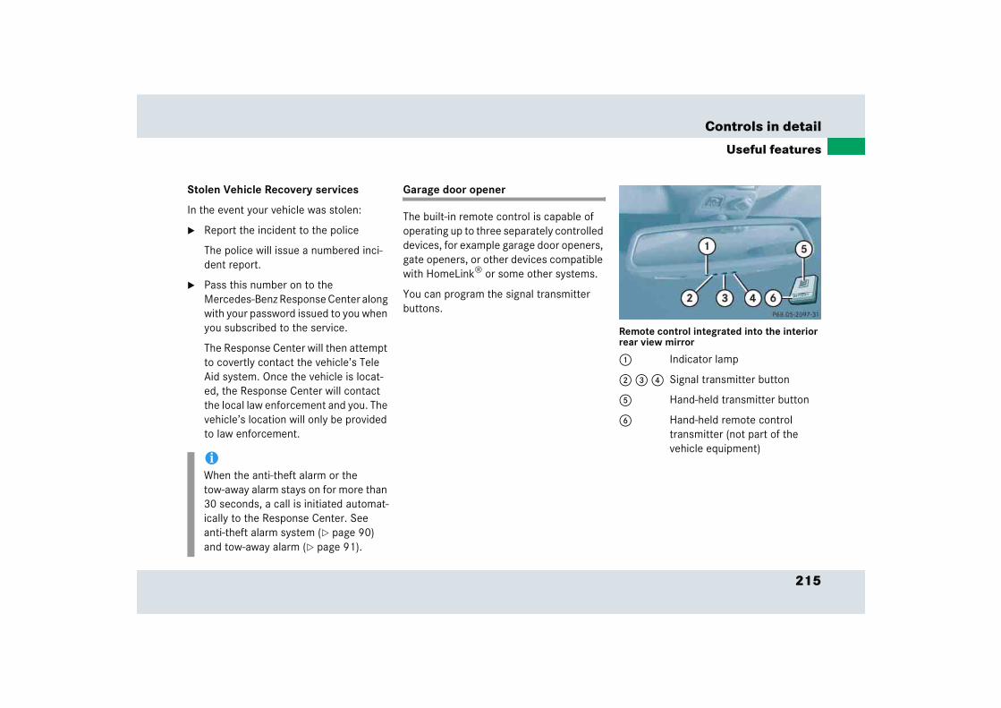
215
Controls in detail
Useful features
Stolen Vehicle Recovery services
In the event your vehicle was stolen:
� Report the incident to the police
The police will issue a numbered inci-dent report.
� Pass this number on to the Mercedes-Benz Response Center along with your password issued to you when you subscribed to the service.
The Response Center will then attempt to covertly contact the vehicle’s Tele Aid system. Once the vehicle is locat-ed, the Response Center will contact the local law enforcement and you. The vehicle’s location will only be provided to law enforcement.
Garage door opener
The built-in remote control is capable of operating up to three separately controlled devices, for example garage door openers, gate openers, or other devices compatible with HomeLink® or some other systems.
You can program the signal transmitter buttons.
Remote control integrated into the interior rear view mirror
1 Indicator lamp
2 3 4 Signal transmitter button
5 Hand-held transmitter button
6 Hand-held remote control transmitter (not part of the vehicle equipment)
iWhen the anti-theft alarm or the tow-away alarm stays on for more than 30 seconds, a call is initiated automat-ically to the Response Center. See anti-theft alarm system (� page 90) and tow-away alarm (� page 91).
216
Controls in detail
Useful features
Warning! G
Before programming the integrated remote control to a garage door opener or gate operator, make sure people and objects are out of the way of the device to prevent po-tential harm or damage. When programming a garage door opener, the door moves up or down. When programming a gate operator, the gate opens or closes.
Do not use the integrated remote control with any garage door opener that lacks safety stop and reverse features as required by U.S. federal safety standards (this includes any garage door opener model manufactured before April 1, 1982). A garage door that cannot detect an object - signaling the door to stop and reverse - does not meet current U.S. federal safety standards.
iCertain types of garage door openers are incompatible with the integrated opener. If you should experience difficulties with programming the transmitter, contact an authorized Mercedes-Benz Center, or call Mercedes-Benz Customer Assistance Center (in the USA) at 1-800-FOR-MERCedes, or Customer Service (in Canada) at 1-888-881-6611.
iUSA only: This device complies with Part 15 of the FCC Rules. Operation is subject to the following two conditions:
(1) This device may not cause harmful interference, and
(2) this device must accept any inter-ference received, including interfer-ence that may cause undesired operation.
Any unauthorized modification to this device could void the user’s authority to operate the equipment.
217
Controls in detail
Useful features
Programming or reprogramming the integrated remote control
Step 1:
� Switch on the ignition (� page 40).
Step 2:
� If you have previously programmed an integrated signal transmitter button and wish to retain its programming, proceed to step 3. Otherwise press and hold the two outer signal transmitter buttons 2 and 4 and release them only when the indicator lamp 1 begins to flash after approximately 20 seconds (do not hold the button for longer than 30 seconds). This proce-dure erases any previous settings for all three channels and initializes the memory. If you later wish to program a second and/or third hand-held trans-mitter to the remaining two signal transmitter buttons, do not repeat this step and begin directly with step 3.
Step 3:
� Hold the end of the hand-held remote control transmitter 6 of the device you wish to train approximately 2 to 5 in (5 to12 cm) away from the surface of the integrated remote control located on the interior rear view mirror, keeping the indicator lamp 1 in view.
Step 4:
� Using both hands, simultaneously press the hand-held transmitter button 5 and the desired integrated signal transmitter button (2, 3 or 4). Do not release the buttons until completing step 5.
The indicator lamp 1 on the integrated remote control will flash, first slowly and then rapidly.
iCanada only:This device complies with RSS-210 of Industry Canada. Operation is subject to the following two conditions:
(1) This device may not cause interfer-ence, and
(2) this device must accept any inter-ference received, including interfer-ence that may cause undesired operation of the device.
Any unauthorized modification to this device could void the user’s authority to operate the equipment.
��

218
Controls in detail
Useful features
Step 5:
� When the indicator lamp 1 flashes rapidly, release both buttons.
Step 6:
� Press and hold the just-trained integrated signal transmitter button and observe the indicator lamp 1.
If the indicator lamp 1 stays on constantly, programming is complete and your device should activate when the integrated signal transmitter button is pressed and released.
Step 7:
� To program the remaining two buttons, repeat the steps above starting with step 3.
Rolling code programming
To train a garage door opener (or other rolling code devices) with the rolling code feature, follow these instructions after completing the “Programming” portion (steps 1 through 6) of this text. (A second person may make the following training procedures quicker and easier.)
Step 8:
� Locate “training” button on the garage door opener motor head unit.
Exact location and color of the button may vary by garage door opener brand. Depending on manufacturer, the “training” button may also be referred to as “learn” or “smart” button. If there is difficulty locating the transmitting button, refer to the garage door opener operator’s manual.
iThe indicator lamp 1 flashes the first time the signal transmitter button is programmed. If this button has already been programmed, the indicator lamp will only start flashing after 20 seconds.
iIf the indicator lamp 1 flashes rapidly for about two seconds and then turns to a constant light, continue with programming steps 8 through 12 as your garage door opener may be equipped with the “rolling code” feature.
��

219
Controls in detail
Useful features
Step 9:
� Press “training” button on the garage door opener motor head unit.
The “training light” is activated.
You have 30 seconds to initiate the following step.
Step 10:
� Firmly press, hold for two seconds and release the programmed integrated signal transmitter button (2, 3 or 4).
Step 11:
� Press, hold for two seconds and release same button a second time to complete the training process.
Some garage door openers (or other rolling code equipped devices) may require you to perform this procedure a third time to complete the training.
Step 12:
� Confirm the garage door operation by pressing the programmed integrated signal transmitter button (2, 3 or 4).
Step 13:
� To program the remaining two buttons, repeat the steps above starting with step 3.
Gate operator/Canadian programming
Canadian radio-frequency laws require transmitter signals to “time-out” (or quit) after several seconds of transmission which may not be long enough for the integrated signal transmitter to pick up the signal during programming. Similar to this Canadian law, some U.S. gate operators are designed to “time-out” in the same manner.
If you live in Canada or if you are having difficulties programming a gate operator (regardless of where you live) by using the programming procedures, replace step 4 with the following:
Step 4:
� Continue to press and hold the integrated signal transmitter button (2, 3 or 4) while you press and re-press (“cycle”) your hand-held remote control transmitter 6 every two seconds until the frequency signal has been learned. Upon successful training, the indicator lamp 1 will flash slowly and then rapidly after several seconds.
� Proceed with programming step 5 and step 6 to complete.
220
Controls in detail
Useful features
Operation of integrated remote control
� Switch on the ignition (� page 40).
� Select and press the appropriate integrated signal transmitter button (2, 3 or 4) to activate the remote controlled device.
The integrated remote control trans-mitter continues to send the signal as long as the button is pressed – up to 20 seconds.
Erasing the integrated remote control memory
� Switch on the ignition (� page 40).
� Simultaneously hold down the signal transmitter buttons 2 and 4, for approximately 20 seconds, until the indicator lamp 1 flashes rapidly. Do not hold for longer than 30 seconds.
The codes of all three channels are erased.
Reprogramming a single integrated signal transmitter button
To program a device using a signal trans-mitter button previously trained, follow these steps:
� Press and hold the desired signal transmitter button (2, 3 or 4). Do not release the button.
� The indicator lamp will begin to flash after 20 seconds. Without releasing the integrated signal transmitter button, proceed with programming starting with step 3.
iIf you sell your vehicle, erase the codes of all three channels.
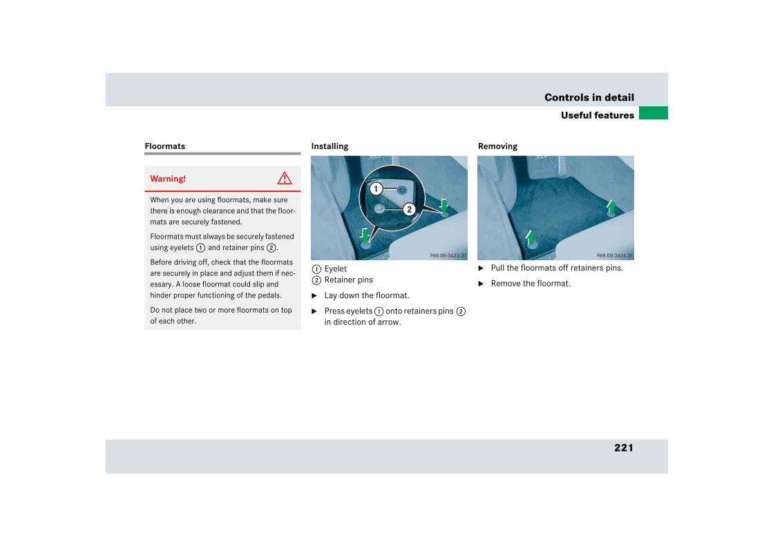
221
Controls in detail
Useful features
Floormats Installing
1 Eyelet2 Retainer pins
� Lay down the floormat.
� Press eyelets 1 onto retainers pins 2 in direction of arrow.
Removing
� Pull the floormats off retainers pins.
� Remove the floormat.
Warning! G
When you are using floormats, make sure there is enough clearance and that the floor-mats are securely fastened.
Floormats must always be securely fastened using eyelets 1 and retainer pins 2.
Before driving off, check that the floormats are securely in place and adjust them if nec-essary. A loose floormat could slip and hinder proper functioning of the pedals.
Do not place two or more floormats on top of each other.
222
Controls in detail
Useful features
Dust cover
Warning! G
Allow the engine to cool down completely before slipping the dust cover on your vehi-cle. Otherwise you could be seriously burned when coming into contact with the hot exhaust system.
!To avoid damage to the vehicle and the dust cover, observe the following:
� Use the dust cover only when the vehicle is garaged.
� Cover the vehicle only when the en-gine has cooled down completely.
� The vehicle as well as the dust cov-er must be dry before slipping the dust cover on the vehicle.
� Remove the padlock that serves as an antitheft device before slipping the dust cover on or off (� page 224).
� To avoid scratches, make sure the zip fastener and the steel cable do not come into contact with the vehi-cle (� page 224).
� Make sure the dust cover is clean and dry before inserting it in the bag provided with the dust cover.
iClean the dust cover according to the care label on the inside of the dust cov-er.
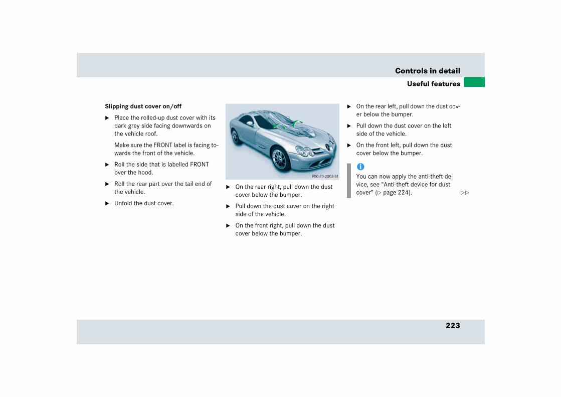
223
Controls in detail
Useful features
Slipping dust cover on/off
� Place the rolled-up dust cover with its dark grey side facing downwards on the vehicle roof.
Make sure the FRONT label is facing to-wards the front of the vehicle.
� Roll the side that is labelled FRONT over the hood.
� Roll the rear part over the tail end of the vehicle.
� Unfold the dust cover.
� On the rear right, pull down the dust cover below the bumper.
� Pull down the dust cover on the right side of the vehicle.
� On the front right, pull down the dust cover below the bumper.
� On the rear left, pull down the dust cov-er below the bumper.
� Pull down the dust cover on the left side of the vehicle.
� On the front left, pull down the dust cover below the bumper.
iYou can now apply the anti-theft de-vice, see “Anti-theft device for dust cover” (� page 224). ��

224
Controls in detail
Useful features
� To remove the dust cover, follow the above steps in reverse order.
Anti-theft device for dust cover
The anti-theft device is located on the low-er edge of the dust cover on the left side of the vehicle.
1 Hook and loop fastener with fabric bor-der
2 Zip fastener3 Elastic band and steel cable4 Eyes5 Padlock1
� Open hook and loop fastener 1.
� Open zip fastener 2.
� Tighten the steel cable by pulling elas-tic band 3.
� Secure both eyes 4 of the steel cable with a padlock 5.
� Close zip fastener 2.
� Close fabric border using hook and loop fastener 1.
1 Not included.
��
225
Controls in detail
Useful features
Roof and trunk lid racks!To avoid damage to the vehicle and the dust cover, observe the following:
� Once you have secured the dust cover with the anti-theft device, the dust cover can be removed only by using force. This can cause damage to the dust cover (tearing) or to the paintwork.
� The dust cover anti-theft device will not prevent burglary or vehicle theft.
Warning! G
This vehicle has not been designed to accommodate any type of roof or trunk lid rack. Therefore do not fit such accessories. Otherwise the rack could fall off and cause serious personal injury.
!Do not use any type of roof or trunk lid rack. Otherwise you will damage the bodywork or paintwork of your SLR.

Operation
The first 1000 miles (1500 km)
Driving instructions
At the gas station
Engine compartment
Trunk
Tires and wheels
Winter driving
Maintenance
Vehicle care

228
Operation
In the “Operation” section you will find detailed information on operating, main-taining and caring for your vehicle.
The first 1000 miles (1500 km)
The more cautiously you treat your vehicle during the break-in period, the more satis-fied you will be with its performance later on. You should therefore observe the fol-lowing for the first 1000 miles (1500 km):
� Drive at varying but moderate road and engine speeds.
� Do not drive faster than 150 mph (240 km/h).
� Break in new tires for the first 100 miles (160 km), therefore avoid high-speed cornering. Do not exceed a speed of 125 mph (200 km/h).
� Do not drive at engine speeds above 4500 rpm.
� Try to avoid heavy load on the engine (driving at full throttle) and driving at high engine speeds (maximum of 2/3 of top speed of each gear) during this break-in period.
� Avoid accelerating by kick-down.
� Change gears in good time.
� Do not attempt to slow the vehicle down by shifting to a lower gear using the gear selector lever.
� Select positions 3, 2 or 1 only when driving at moderate speeds (for hill driving).
� Select C as the preferred shift program (� page 173) for the first 1000 miles 1500 km).
After 1000 miles (1500 km), you may grad-ually bring the vehicle up to full road and engine speed.
All of the above instructions also apply when driving the first 1000 miles (1500 km) after the engine or the rear dif-ferential has been replaced.
iAlways obey applicable speed limits.

229
Operation
Driving instructions
� Driving instructionsDrive sensibly – save fuel
Fuel consumption, to a great extent, depends on driving habits and operating conditions.
To save fuel you should:
� Keep tires at the recommended tire inflation pressures.
� Remove unnecessary loads.
� Allow engine to warm up under low load use.
� Avoid frequent acceleration and decel-eration.
� Have all maintenance work performed at the intervals specified in the Maintenance Booklet and as required by the maintenance service display. Contact an authorized Mercedes-Benz Center.
Fuel consumption is also increased by driving in cold weather, in stop-and-go traffic, on short trips and in hilly area.
Drinking and driving Pedals
Warning! G
Drinking and driving and/or taking drugs and driving are very dangerous combina-tions. Even a small amount of alcohol or drugs can affect your reflexes, perceptions and judgement.
The possibility of a serious or even fatal accident are greatly increased when you drink or take drugs and drive.
Do not drink or take drugs and drive or allow anyone to drive who has been drinking or taking drugs.
Warning! G
Keep driver’s foot area clear at all times. Objects stored in this area may impair pedal movement.
230
Operation
Driving instructions
Power assistance Brakes
Warning! G
The brake system requires electrical energy for operation.
A malfunction in the vehicle’s power supply or electrical system may impair brake sys-tem operation and switch it into its emer-gency operation mode. In such a case, the red brake warning lamp (� page 298) and warning messages (� page 304) in the in-strument cluster come on while driving. To brake, the driver must then apply signifi-cantly greater brake pedal pressure and de-press the pedal much further to obtain the expected braking effect. If necessary, apply full pressure to the brake pedal. Brakes are only applied to the front wheels. Stopping distance is increased! If there is a malfunc-tion in the SBC brake system, we recom-mend that the vehicle be transported with all wheels off the ground using flatbed or ap-propriate wheel lift/dolly equipment.
A tow bar must be used if circumstances do not permit the use of the recommended towing methods and the vehicle requires towing with all four wheels on the ground. Towing the vehicle with all four wheels on the ground is only permissible for distances up to 30 miles (50 km) and at a speed not to exceed 30 mph (50 km/h). For more infor-mation, see “Towing the vehicle” (� page 357).
With the engine not running, there is no power assistance for the brake and steering systems. In this case, it is important to keep in mind that a considerably higher degree of effort is necessary to brake and steer the ve-hicle.
Warning! G
After driving in heavy rain for some time without applying the brakes or through wa-ter deep enough to wet brake components, the first braking action may be somewhat reduced and increased pedal pressure may be necessary to obtain expected braking ef-fect. Maintain a safe distance from vehicles in front.
Resting your foot on the brake pedal will cause excessive and premature wear of the brake pads.
It can also result in the brakes overheating thereby significantly reducing their effec-tiveness. It may not be possible to stop the vehicle in sufficient time to avoid an acci-dent.

231
Operation
Driving instructions
After driving on wet or snow-covered roads, you should apply your brakes firmly before parking your vehicle. This produces heat which serves to dry the brake disks.
If the parking brake is released and the red brake warning lamp in the instrument clus-ter stays on, there is a malfunction in the SBC brake system (� page 298) or the brake fluid level in the reservoir is too low.
Brake pad wear or a leak in the system may be the reason for low brake fluid in the res-ervoir.
Have the brake system inspected immedi-ately.
All checks and service work on the brake system should be carried out by qualified technicians only. Contact an authorized Mercedes-Benz Center.
Only install brake pads and brake fluid rec-ommended by Mercedes-Benz.
After hard braking, it is advisable to drive on for some time, rather than immediately park the vehicle, so the air stream will cool down the brakes faster.
iThe brake system is designed to decel-erate your SLR from high speeds at the best possible rate. Depending on the applied brake force, speed, and ambi-ent conditions, the brake system may produce a squeak-type noise when you apply the brakes at a moderate rate. If you experience this noise, you should occasionally test the effectiveness of the brakes by applying above-normal braking pressure at high speeds. This will also enhance the grip of the brake pads.
Warning! G
Make sure not to endanger any other road users when carrying out these braking maneuvers.
!Refer to the description of the Brake Assist System (BAS) (� page 81).
Warning! G
If other than recommended brake pads are installed, or other than recommended brake fluid is used, the braking properties of the vehicle can be degraded to an extent that safe braking is substantially impaired. This could result in an accident.
Be certain to read and observe the warning notices on brake pad replacement (� page 85).
!When driving down long and steep grades, relieve the load on the brakes by shifting into a lower gear to use the engine’s braking power. This helps pre-vent overheating of the brakes and re-duces brake pad wear.
232
Operation
Driving instructions
Driving off
Apply the brakes to test them briefly after driving off. Perform this procedure only when the road is clear of other traffic.
Warm up the engine smoothly. Do not place full load on the engine until the operating temperature has been reached (� page 301).
When starting off on a slippery surface, do not allow a drive wheel to spin for an extended period with the ESP switched off. Doing so may cause serious damage to the drivetrain which is not covered by the Mercedes-Benz Limited Warranty.
Parking
!Simultaneously depressing the accelerator pedal and applying the brake reduces engine performance and causes premature brake and drivetrain wear.
!Set the parking brake whenever park-ing or leaving the vehicle. In addition, move gear selector lever to position P.
When parking on hills, always turn front wheels towards the road curb.
Warning! G
Do not park this vehicle in areas where com-bustible materials such as grass, hay or leaves can come into contact with the hot exhaust system, as these materials could be ignited and cause a vehicle fire.
To reduce the risk of personal injury as a re-sult of vehicle movement, before turning off the engine and leaving the vehicle always:
� Keep right foot on brake pedal.
� Pull the parking brake lever up as many notches as possible.
� Move the gear selector lever to position P.
� Slowly release brake pedal.
� When parked on an incline, turn front wheels towards the road curb.
� Turn the SmartKey in the starter switch to position 0 and remove the SmartKey from the starter switch.
� Take the SmartKey with you and lock the vehicle when leaving.
233
Operation
Driving instructions
Tires
Treadwear indicators (TWI) are required by law. These indicators are located in six places on the tread circumference and become visible at a tread depth of approximately 1/16 in (1.6 mm), at which point the tire is considered worn and should be replaced.
The treadwear indicator appears as a solid band across the tread.
Specified tire inflation pressures must be maintained. This applies particularly if the tires are subjected to high loads (e.g. high speeds, heavy loads, high ambient temper-atures).
Warning! G
If you feel a sudden significant vibration or ride disturbance, or you suspect that possi-ble damage to your vehicle has occurred, you should turn on the hazard warning flash-ers, carefully slow down, and drive with cau-tion to an area which is a safe distance from the road.
Inspect the tires and the vehicle underbody for possible damage. If the vehicle or tires appear unsafe, have it towed to the nearest Mercedes-Benz Center or tire dealer for repairs.
Warning! G
Although the applicable federal motor vehicle safety laws consider a tire to be worn when the treadwear indicators (TWI) become visible at approximately 1/16 in (1.6 mm), we recommend that you do not allow your tires to wear down to that level. As tread depth approaches 1/8 in (3 mm), the adhesion properties on a wet road are sharply reduced.
Depending upon the weather and/or road surface (conditions), the tire traction varies widely.
Have worn tires replaced in pairs (front pair or rear pair). Otherwise the driving stability of the vehicle will be adversely affected.
Warning! G
Do not drive with a flat tire. A flat tire affects the ability to steer or brake the vehicle. You may lose control of the vehicle. Continued driving with a flat tire or driving at high speed with a flat tire will cause excessive heat build-up and possibly a fire.
!A wheel change should only be carried out at an authorized Mercedes-Benz Center. Otherwise there is a danger of damaging the vehicle by jacking it up incorrectly.
234
Operation
Driving instructions
Hydroplaning
Depending on the depth of the water layer on the road, hydroplaning may occur, even at low speeds and with new tires. Reduce vehicle speed, avoid track grooves in the road and apply brakes cautiously in the rain.
Tire traction
The safe speed on a wet, snow covered or icy road is always lower than on a dry road.
You should pay particular attention to the condition of the road whenever the outside temperatures are close to the freezing point.
Mercedes-Benz recommends M+S rated radial-ply tires with a minimum tread depth of approximately 1/6 in (4 mm) on all four wheels for the winter season to ensure normal balanced handling characteristics. On packed snow, they can reduce your stopping distance compared to summer tires. Stopping distance, however, is still
considerably greater than when the road is not covered with snow or ice. Exercise ap-propriate caution.
Tire speed rating
Regardless of the tire speed rating, local speed limits should be obeyed. Use prudent driving speeds appropriate to prevailing conditions.
Warning! G
If ice has formed on the road, tire traction will be substantially reduced. Under such weather conditions, drive, steer and brake with extreme caution.
!Avoid spinning of a drive wheel. This may cause serious damage to the drivetrain which is not covered by the Mercedes-Benz Limited Warranty.
235
Operation
Driving instructions
Your vehicle is factory equipped with “(Y)”-rated tires, which have a speed rating of over 186 mph (300 km/h).
Winter driving instructions
The most important rule for slippery or icy roads is to drive sensibly and to avoid abrupt acceleration, braking and steering maneuvers. Do not use the cruise control system under such conditions.
When the vehicle is in danger of skidding, move gear selector lever to position N. Try to keep the vehicle under control by corrective steering action.
Road salts and chemicals can adversely affect braking efficiency. Increased pedal force may become necessary to produce the normal braking effect.
Depressing the brake pedal periodically when traveling at length on salt-strewn roads can bring road-salt-impaired braking efficiency back to normal.
If the vehicle is parked after being driven on salt-treated roads, the braking efficiency should be tested as soon as possible after driving is resumed.
Warning! G
Even when permitted by law, never operate a vehicle at speeds greater than the maxi-mum speed rating of the tires.
Exceeding the maximum speed for which tires are rated can lead to sudden tire failure, causing loss of vehicle control and possibly resulting in an accident and/or personal injury and possible death, for you and for others.
iFor information on tire speed rating for winter tires, see “Winter tires*” (� page 284).
For additional general information on tire speed markings on tire sidewall, see “Tire speed rating” (� page 271).
iFor information on driving with snow chains, see “Snow chains” (� page 285).
Warning! G
On slippery road surfaces, never downshift in order to obtain braking action. This could result in drive wheel slip and reduced vehicle control. Your vehicle’s ABS will not prevent this type of control loss.
Warning! G
Make sure not to endanger any other road users when carrying out these braking maneuvers.
236
Operation
Driving instructions
For more information, see “Winter driving” (� page 284).
Standing water Passenger compartment
Driving abroad
Abroad, there is an extensive Mercedes-Benz service network at your disposal. If you plan to drive into areas which are not listed in the index of your Mercedes-Benz Center directory, you should request pertinent information from an authorized Mercedes-Benz Center.
Warning! G
If the vehicle becomes stuck in snow, make sure snow is kept clear of the exhaust pipe and from around the vehicle with the engine running. Otherwise deadly carbon monoxide (CO) gases may enter vehicle interior result-ing in unconsciousness and death.
To assure sufficient fresh air ventilation, open a window slightly on the side of the vehicle not facing the wind.
Warning! G
The outside temperature indicator is not designed to serve as an ice-warning device and is therefore unsuitable for that purpose. Indicated temperatures just above the freezing point do not guarantee that the road surface is free of ice.
!Do not drive through flooded areas or water of unknown depth. Before driving through water, determine its depth. Never accelerate before driving into water. The bow wave could force water into the engine and auxiliary equip-ment, thus damaging them.
If you must drive through standing wa-ter, drive slowly to prevent water from entering the passenger compartment or the engine compartment. Water in these areas could cause damage to electrical components or wiring of the engine or transmission, or could result in water being ingested by the engine through the air intake causing severe internal engine damage. Any such damage is not covered by the Mercedes-Benz Limited Warranty.
Warning! G
Always fasten items being carried as securely as possible.
In an accident, during hard braking or sud-den maneuvers, loose items will be thrown around inside the vehicle, and cause injury to vehicle occupants unless the items are securely fastened in the vehicle.
The trunk is the preferred place to carry objects.
237
Operation
Driving instructions
Control and operation of radio transmitters
Radio and telephone
Telephones and two-way radios
Radio transmitters, such as a portable telephone or a citizens band unit should only be used inside the vehicle if they are connected to an antenna that is installed on the outside of the vehicle.
Refer to the radio transmitter operation instructions regarding use of an external antenna.
Catalytic converter
Your Mercedes-Benz is equipped with monolithic-type catalytic converters, an important element in conjunction with the oxygen sensors to achieve substantial control of the pollutants in the exhaust emissions. Keep your vehicle in proper operating condition by following our recommended maintenance instructions as outlined in your Maintenance Booklet.
Warning! G
Please do not forget that your primary responsibility is to drive the vehicle safely. Only operate the radio or telephone1 if road, weather and traffic conditions permit.
Bear in mind that at a speed of just 30 mph (approximately 50 km/h), your vehicle is covering a distance of 44 feet (approximately 14 m) every second.
1 Observe all legal requirements.
Warning! G
Never operate radio transmitters equipped with a built-in or attached antenna (i.e. with-out being connected to an external antenna) from inside the vehicle while the engine is running. Doing so could lead to a malfunc-tion of the vehicle’s electronic system, possibly resulting in an accident and personal injury. !
To prevent damage to the catalytic converters, only use premium unleaded gasoline in this vehicle.
Any noticeable irregularities in engine operation should be repaired promptly. Otherwise excessive unburned fuel may reach the catalytic converter, causing it to overheat and potentially start a fire.
238
Operation
Driving instructions
Emission control
Certain systems of the engine serve to keep the toxic components of the exhaust gases within permissible limits required by law.
These systems, of course, will function properly only when maintained strictly according to factory specifications. Any adjustments on the engine should, therefore, be carried out only by qualified Mercedes-Benz Center authorized techni-cians. Engine adjustments should not be altered in any way. Moreover, the specified service jobs must be carried out regularly according to Mercedes-Benz servicing requirements. For details refer to the Maintenance Booklet.
Warning! G
As with any vehicle, do not idle, park or operate this vehicle in areas where combus-tible materials such as grass, hay or leaves can come into contact with the hot exhaust system, as these materials could be ignited and cause a vehicle fire.
Warning! G
The exhaust areas on the engine hood and between the doors and front wheels get very hot. Avoid contact with them, otherwise there is the risk of severe burns.
Warning! G
Inhalation of exhaust gas is hazardous to your health. All exhaust gas contains carbon monoxide, and inhaling it can cause unconsciousness and lead to death.
Do not run the engine in confined areas (such as a garage) which are not properly ventilated. If you think that exhaust gas fumes are entering the vehicle while driving, have the cause determined and corrected immediately. If you must drive under these conditions, drive only with at least one window fully open at all times.

239
Operation
Driving instructions
Coolant temperature
During severe operating conditions and stop-and-go city traffic, the coolant temperature may rise close to approximately 248°F (120°C).
The engine should not be operated with the coolant temperature over 248°F (120°C). Doing so may cause serious engine damage which is not covered by the Mercedes-Benz Limited Warranty.
Warning! G
� Driving when your engine is badly overheated can cause some fluids, which may have leaked into the engine compartment, to catch fire. You could be seriously burned.
� Steam from an overheated engine can cause serious burns and can occur just by opening the hood. Stay away from the engine if you see or hear steam com-ing from it.
Turn off the engine, get out of the vehicle and do not stand near the vehicle until the engine has cooled down.
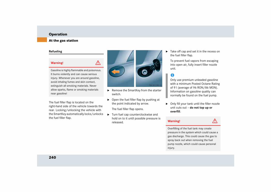
240
Operation
At the gas station
Refueling
The fuel filler flap is located on the right-hand side of the vehicle towards the rear. Locking/unlocking the vehicle with the SmartKey automatically locks/unlocks the fuel filler flap.
� Remove the SmartKey from the starter switch.
� Open the fuel filler flap by pushing at the point indicated by arrow.
The fuel filler flap opens.
� Turn fuel cap counterclockwise and hold on to it until possible pressure is released.
� Take off cap and set it in the recess on the fuel filler flap.
To prevent fuel vapors from escaping into open air, fully insert filler nozzle unit.
� Only fill your tank until the filler nozzle unit cuts out – do not top up or overfill.
Warning! G
Gasoline is highly flammable and poisonous. It burns violently and can cause serious injury. Whenever you are around gasoline, avoid inhaling fumes and skin contact, extinguish all smoking materials. Never allow sparks, flame or smoking materials near gasoline!
iOnly use premium unleaded gasoline with a minimum Posted Octane Rating of 91 (average of 96 RON/86 MON). Information on gasoline quality can normally be found on the fuel pump.
Warning! G
Overfilling of the fuel tank may create pressure in the system which could cause a gas discharge. This could cause the gas to spray back out when removing the fuel pump nozzle, which could cause personal injury.

241
Operation
At the gas station
� Replace fuel cap by turning it clockwise.
You will hear when fuel cap is tightened.
� Close the fuel filler flap until you hear the latch close shut.
Check regularly and before a long trip
1 Coolant2 Engine oil3 Brake fluid
Coolant
For normal replenishing, use water (pota-ble water quality). For more information, see “Coolant” (� page 249) and see “Fu-els, coolants, lubricants, etc.” (� page 375).
Engine oil level
For more information on engine oil level, see “Engine oil” (� page 246).
Brake fluid
iMore information on gasoline can be found in the Factory Approved Service Products pamphlet.
Leaving the engine running and the fuel cap open can cause the ú malfunc-tion indicator lamp (USA only) or the ± malfunction indicator lamp (Canada only) to illuminate.
For more information, see “Practical hints” (� page 299).
iOpening the hood, see (� page 243).
!If you find that the brake fluid in the brake fluid reservoir has fallen to the minimum mark or below, have the brake system checked for brake pad thickness and leaks immediately. Notify an authorized Mercedes-Benz Center immediately. Do not add brake fluid as this will not solve the problem. For more information, see “Practical hints” (� page 298).
242
Operation
At the gas station
Windshield washer and headlamp cleaning system
For more information on filling up the washer reservoir, see “Windshield washer system and headlamp cleaning system” (� page 251).
Vehicle lighting
Check function and cleanliness. For more information on replacing light bulbs, see “Replacing bulbs” (� page 346).
Exterior lamp switch (� page 105).
Tire inflation pressure
For more information on tire inflation pres-sure, see “Checking tire inflation pressure manually” (� page 264).
243
Operation
Engine compartment
� Engine compartmentHood Opening
Warning! G
Do not pull the release lever while the vehicle is in motion. Otherwise the hood could be forced open by passing air flow.
Warning! G
The exhaust areas on the engine hood and between the doors and front wheels get very hot. Avoid contact with them, otherwise there is the risk of severe burns.
Warning! G
To help prevent personal injury, stay clear of moving parts when the hood is open and the engine is running. Make sure the hood is properly closed before driving. When closing the hood, use extreme caution not to catch hands or fingers.
The radiator fan may also start at any time automatically, even after the SmartKey has been removed from the starter switch. Stay clear of fan blades.
Warning! G
Engine components may become very hot. Avoid contact with them, otherwise there is the risk of severe burns.
Warning! G
The engine is equipped with a transistorized ignition system. Because of the high voltage it is dangerous to touch any components (ignition coils, spark plug sockets, diagnos-tic socket) of the ignition system
� with the engine running
� while starting the engine
� if ignition is “on” and the engine is turned manually

244
Operation
Engine compartment
The release lever is located in the driver's footwell.
1 Release lever
The hood folding mechanism is disengaged in two stages.
� Pull release lever 1 downwards.
This completes the first stage.
!Make sure the windshield wipers are not folded away from the windshield. Otherwise the windshield wipers or the hood could be damaged.
Make sure there is sufficient clearance before opening the hood. A minimum clearance in front of the vehicle of 3/4 ft (25 cm) is required.
iIf it was not possible to release the hood, pull the release lever downwards more firmly.
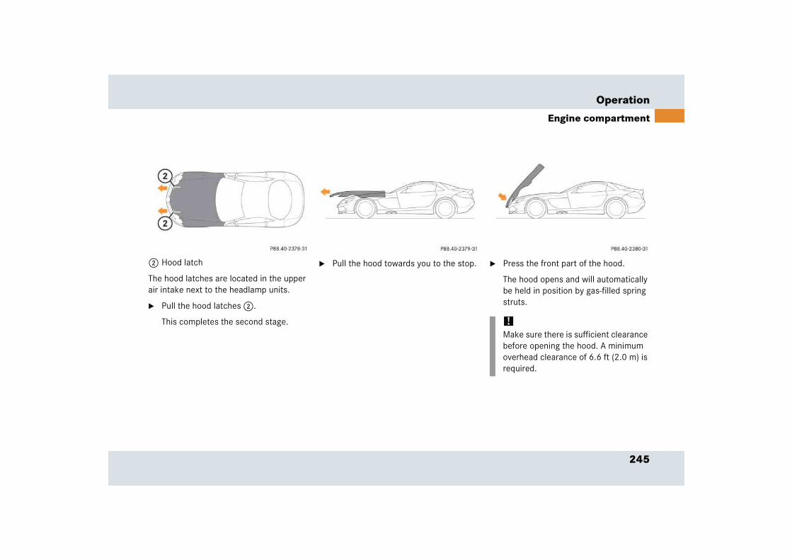
245
Operation
Engine compartment
2 Hood latch
The hood latches are located in the upper air intake next to the headlamp units.
� Pull the hood latches 2.
This completes the second stage.
� Pull the hood towards you to the stop. � Press the front part of the hood.
The hood opens and will automatically be held in position by gas-filled spring struts.
!Make sure there is sufficient clearance before opening the hood. A minimum overhead clearance of 6.6 ft (2.0 m) is required.
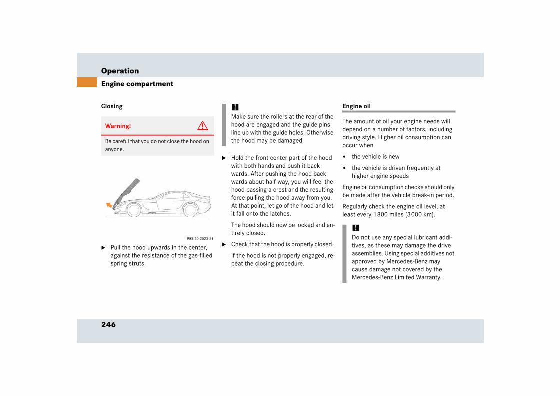
246
Operation
Engine compartment
Closing
� Pull the hood upwards in the center, against the resistance of the gas-filled spring struts.
� Hold the front center part of the hood with both hands and push it back-wards. After pushing the hood back-wards about half-way, you will feel the hood passing a crest and the resulting force pulling the hood away from you. At that point, let go of the hood and let it fall onto the latches.
The hood should now be locked and en-tirely closed.
� Check that the hood is properly closed.
If the hood is not properly engaged, re-peat the closing procedure.
Engine oil
The amount of oil your engine needs will depend on a number of factors, including driving style. Higher oil consumption can occur when
� the vehicle is new
� the vehicle is driven frequently at higher engine speeds
Engine oil consumption checks should only be made after the vehicle break-in period.
Regularly check the engine oil level, at least every 1800 miles (3000 km).
Warning! G
Be careful that you do not close the hood on anyone.
!Make sure the rollers at the rear of the hood are engaged and the guide pins line up with the guide holes. Otherwise the hood may be damaged.
!Do not use any special lubricant addi-tives, as these may damage the drive assemblies. Using special additives not approved by Mercedes-Benz may cause damage not covered by the Mercedes-Benz Limited Warranty.
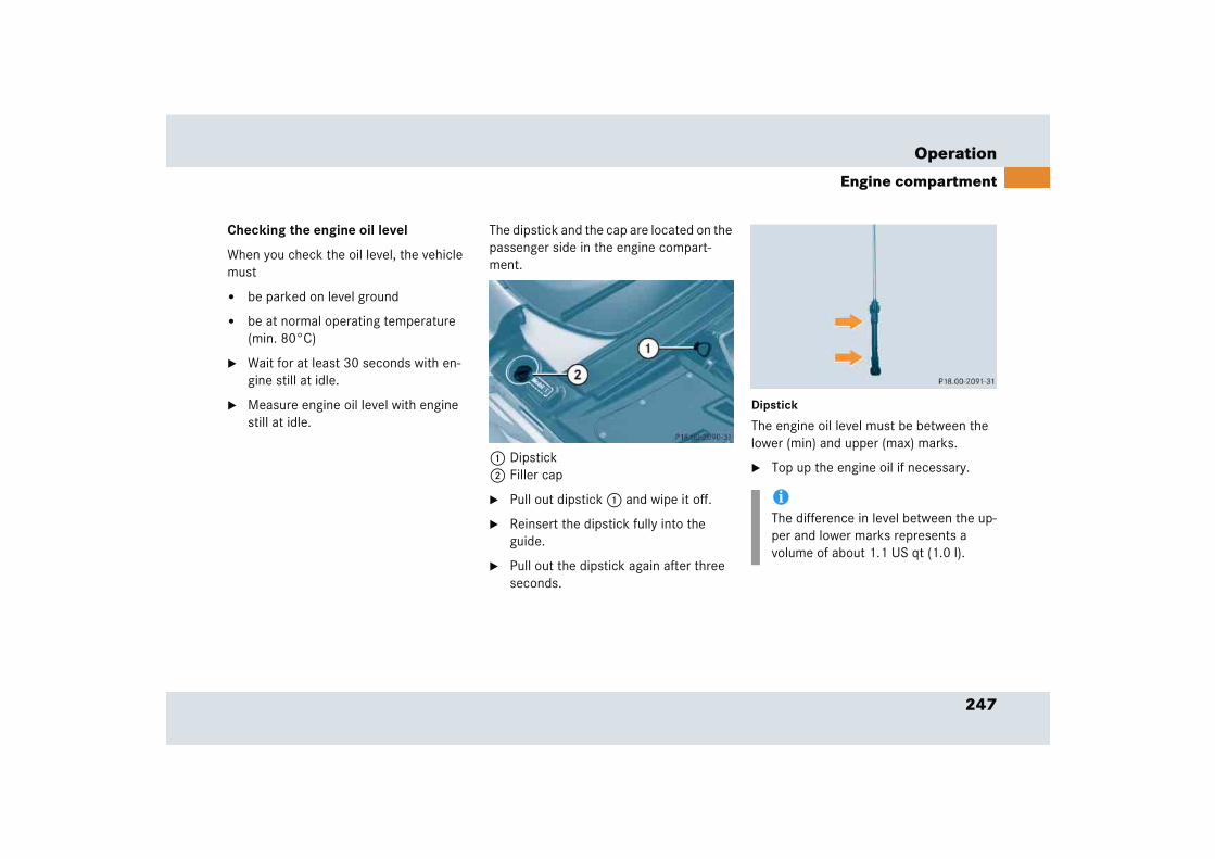
247
Operation
Engine compartment
Checking the engine oil level
When you check the oil level, the vehicle must
� be parked on level ground
� be at normal operating temperature (min. 80°C)
� Wait for at least 30 seconds with en-gine still at idle.
� Measure engine oil level with engine still at idle.
The dipstick and the cap are located on the passenger side in the engine compart-ment.
1 Dipstick2 Filler cap
� Pull out dipstick 1 and wipe it off.
� Reinsert the dipstick fully into the guide.
� Pull out the dipstick again after three seconds.
Dipstick
The engine oil level must be between the lower (min) and upper (max) marks.
� Top up the engine oil if necessary.
iThe difference in level between the up-per and lower marks represents a volume of about 1.1 US qt (1.0 l).

248
Operation
Engine compartment
Adding engine oil
� Using a rag, unscrew filler cap 2 from filler neck.
� Add engine oil as required. Be careful not to overfill with oil.
Be careful not to spill any oil when adding. Avoid environmental damage caused by oil entering the ground or water.
� Screw the filler cap back on filler neck.
You will find further information about en-gine oil in the “Technical data” section (� page 377) and (� page 375).
Transmission fluid level
The transmission fluid level does not need to be checked. If you notice transmission fluid loss or gear shifting malfunctions, have an authorized Mercedes-Benz Center check the transmission.
Warning! G
The filler cap on the filler neck could be hot.
Use a rag when you unscrew the filler cap. Otherwise you could burn yourself.
!Only use approved engine oils and oil filters required for vehicles with Maintenance System. For a listing of approved engine oils and oil filters, refer to the Factory Approved Service Products pamphlet in your vehicle literature portfolio, or contact an authorized Mercedes-Benz Center.
Using engine oils and oil filters of specification other than those expressly required for the Maintenance System, or changing of oil and oil filter at change intervals longer than those called for by the Maintenance System will result in engine damage not cov-ered by the Mercedes-Benz Limited Warranty.
!Excess oil must be siphoned or drained off. It could cause damage to the engine and catalytic converter not covered by the Mercedes-Benz Limited Warranty.
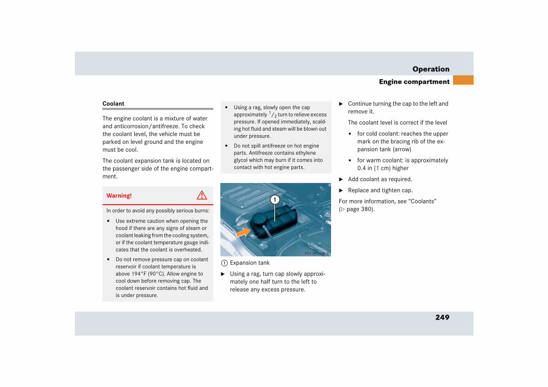
249
Operation
Engine compartment
Coolant
The engine coolant is a mixture of water and anticorrosion/antifreeze. To check the coolant level, the vehicle must be parked on level ground and the engine must be cool.
The coolant expansion tank is located on the passenger side of the engine compart-ment.
1 Expansion tank
� Using a rag, turn cap slowly approxi-mately one half turn to the left to release any excess pressure.
� Continue turning the cap to the left and remove it.
The coolant level is correct if the level
� for cold coolant: reaches the upper mark on the bracing rib of the ex-pansion tank (arrow)
� for warm coolant: is approximately 0.4 in (1 cm) higher
� Add coolant as required.
� Replace and tighten cap.
For more information, see “Coolants” (� page 380).
Warning! G
In order to avoid any possibly serious burns:
� Use extreme caution when opening the hood if there are any signs of steam or coolant leaking from the cooling system, or if the coolant temperature gauge indi-cates that the coolant is overheated.
� Do not remove pressure cap on coolant reservoir if coolant temperature is above 194°F (90°C). Allow engine to cool down before removing cap. The coolant reservoir contains hot fluid and is under pressure.
� Using a rag, slowly open the cap approximately 1/2 turn to relieve excess pressure. If opened immediately, scald-ing hot fluid and steam will be blown out under pressure.
� Do not spill antifreeze on hot engine parts. Antifreeze contains ethylene glycol which may burn if it comes into contact with hot engine parts.
250
Operation
Trunk
Batteries
Your vehicle is equipped with two batter-ies.
� Starter battery in the trunk
� Consumer battery in the trunk
These batteries should always be suffi-ciently charged in order to achieve its rat-ed service life. A flat battery must be fully recharged. Refer to Maintenance Booklet for battery maintenance intervals.
If you use your vehicle mostly for short-distance trips, you will need to have the battery charge checked more frequently.
When replacing batteries, always use bat-teries approved by Mercedes-Benz. Have this work only carried out by an authorized Mercedes-Benz Center.
If you do not intend to operate your vehicle for an extended period of time, consult an authorized Mercedes-Benz Center about steps you need to observe.
For more information on battery mainte-nance, see “Batteries” (� page 354).
GObserve all safety instructions and precautions when handling automotive batteries.
A Risk of explosion
D Keep flames or sparks away from battery. Do not smoke.
B Battery acid is caustic. Do not allow it to come into contact with skin, eyes or clothing.
In case it does, immediately flush affected area with clean water and seek medical help if necessary.
E Wear eye protection.
C Keep children away.
F Follow the instructions in thisOperator’s Manual.
!You must not jump start the vehicle, otherwise the vehicle electrical sys-tems could be damaged.
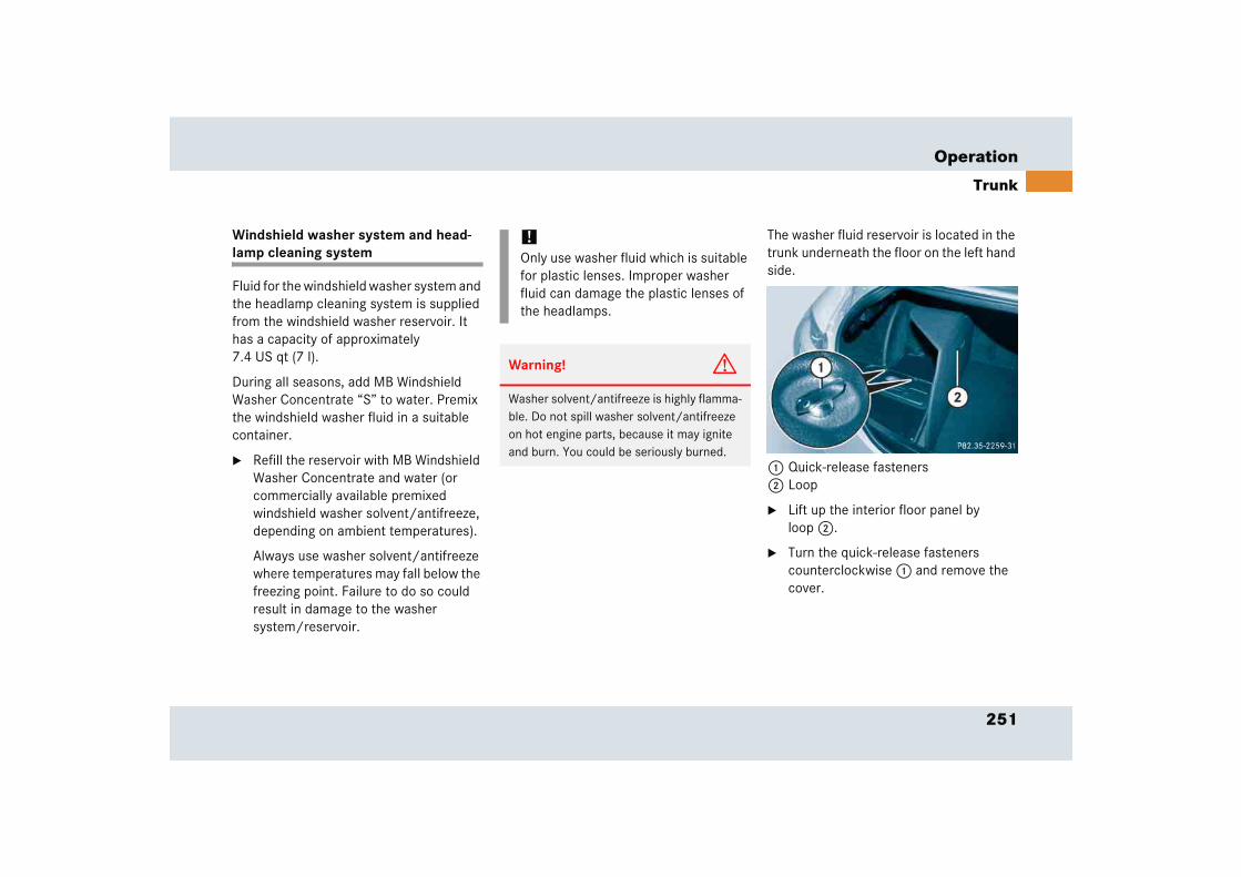
251
Operation
Trunk
Windshield washer system and head-lamp cleaning system
Fluid for the windshield washer system and the headlamp cleaning system is supplied from the windshield washer reservoir. It has a capacity of approximately 7.4 US qt (7 l).
During all seasons, add MB Windshield Washer Concentrate “S” to water. Premix the windshield washer fluid in a suitable container.
� Refill the reservoir with MB Windshield Washer Concentrate and water (or commercially available premixed windshield washer solvent/antifreeze, depending on ambient temperatures).
Always use washer solvent/antifreeze where temperatures may fall below the freezing point. Failure to do so could result in damage to the washer system/reservoir.
The washer fluid reservoir is located in the trunk underneath the floor on the left hand side.
1 Quick-release fasteners2 Loop
� Lift up the interior floor panel by loop 2.
� Turn the quick-release fasteners counterclockwise 1 and remove the cover.
!Only use washer fluid which is suitable for plastic lenses. Improper washer fluid can damage the plastic lenses of the headlamps.
Warning! G
Washer solvent/antifreeze is highly flamma-ble. Do not spill washer solvent/antifreeze on hot engine parts, because it may ignite and burn. You could be seriously burned.

252
Operation
Trunk
3 Cap for windshield washer reservoir
Opening washer fluid reservoir
� Pull up cap 3 by the tab.
Closing washer fluid reservoir
� Press cap 3 on to the filler neck until it engages fully.
For more information, see “Windshield and headlamp washer system” (� page 382).
253
Operation
Tires and wheels
� Tires and wheelsFor safety reasons, Mercedes-Benz recom-mends that you only use tires approved by Mercedes-Benz for use on SLR vehicles.
See an authorized Mercedes-Benz Center for information on tested and recommended rims and tires for summer and winter operation. They can also offer advice concerning tire service and purchase.
Retreaded tires are not tested or recom-mended by Mercedes-Benz, since previous damage cannot always be recognized on retreads. The operating safety of the vehicle cannot be assured when such tires are used.
Important guidelines
� For the first 100 miles (160 km) avoid high-speed cornering. Do not exceed a speed of 125 mph (200 km/h).1
� Only use sets of tires and rims of the same type and make.
� Tires must be of the correct size for the rim.
� Regularly check the tires and rims for damage. Dented or bent rims can cause tire inflation pressure loss and damage to the tire beads.
Warning! G
Replace rims or tires with the same designa-tion, manufacturer and type as shown on the original part. See an authorized Mercedes-Benz Center for further informa-tion. If incorrectly sized rims and tires are mounted:
� The wheel brakes or suspension components can be damaged.
� The operating clearance of the wheels and the tires may no longer be correct.
Warning! G
Worn, old tires can cause accidents. If the tire tread is badly worn, or if the tires have sustained damage, replace them.
When replacing rims, only use genuine Mercedes-Benz wheel bolts specified for the particular rim type. Failure to do so can result in the bolts loosening and possibly an accident.
!A wheel change should only be carried out at an authorized Mercedes-Benz Center. Otherwise there is a danger of damaging the vehicle by jacking it up incorrectly.
1 Please always drive carefully and obey applicable speed limits.

254
Operation
Tires and wheels
� If vehicle is heavily loaded, check tire inflation pressure and correct as required.
� Do not allow your tires to wear down too far. Adhesion properties on wet roads are sharply reduced at tread depths under 1/8 in (3 mm).
� When replacing individual tires, you should mount new tires on the front wheels first (on vehicles with same-sized wheels all around).
Tire care and maintenance
Regularly check your tire inflation pressure at least once a month. For more informa-tion on checking tire inflation pressure, see “Recommended tire inflation pres-sure” (� page 262).
Tire inspection
Every time you check your tire inflation pressure, you should also inspect your tires for the following:
� excessive treadwear (� page 255)
� cord or fabric showing through the tire’s rubber
� bumps, bulges, cuts, cracks or splits in the tread or side of the tire
Replace the tire if you find any of the above conditions.
Life of tire
The service life of a tire is dependent upon varying factors including but not limited to:
� Driving style
� Tire inflation pressure
� Distance drivenWarning! G
Regularly check the tires for damage. Dam-aged tires can cause tire inflation pressure loss. As a result, you could lose control of your vehicle.
Worn, old tires can cause accidents. If the tire tread is badly worn, or if the tires have sustained damage, replace them.
Have worn or damaged tires replaced in pairs (front pair or rear pair). Otherwise the driving stability of the vehicle will be ad-versely affected.
Warning! G
Have worn or damaged tires replaced in pairs (front pair or rear pair). Otherwise, the driving stability of the vehicle will be ad-versely affected.
Warning! G
Tires should be replaced after six years, regardless of the remaining tread.

255
Operation
Tires and wheels
Tread depth
Do not allow your tires to wear down too far. Adhesion properties on wet roads are sharply reduced at tread depths under 1/8 in (3 mm).
Treadwear indicators (TWI) are required by law. These indicators are located in six places on the tread circumference and become visible at a tread depth of approx-imately 1/16 in (1.6 mm), at which point the tire is considered worn and should be replaced.
Recommended minimum tire tread depth:
� Summer tires 1/8 in (3 mm)
� Winter tires 1/6 in (4 mm)
1 TWI (TreadWear Indicator)
The treadwear indicator appears as a solid band across the tread.
Storing tires
Cleaning tires
Warning! G
Although the applicable federal motor safety laws consider a tire to be worn when the treadwear indicators (TWI) become visible at approximately 1/16 in (1.6 mm), we recom-mend that you do not allow your tires
to wear down to that level. As tread depth approaches 1/8 in (3 mm), the adhesion properties on a wet road are sharply reduced.
Depending upon the weather and/or road surface (conditions), the tire traction varies widely.
!Keep unmounted tires in a cool, dry place with as little exposure to light as possible. Protect tires from contact with oil, grease and gasoline.
!Never use a round nozzle to power wash tires. The intense jet of water can result in damage to the tire.
Always replace a damaged tire.
Warning! G
Have worn or damaged tires replaced in pairs (front pair or rear pair). Otherwise, the driving stability of the vehicle will be ad-versely affected.
256
Operation
Tires and wheels
Direction of rotation
Unidirectional tires offer added advan-tages, such as better hydroplaning perfor-mance. To benefit, however, you must make sure the tires rotate in the direction specified.
An arrow on the sidewall indicates the intended direction of rotation (spinning) of the tire.
Loading the vehicle
Two labels on your vehicle show how much weight it may properly carry.
� The Tire and Loading Information placard (Example A) or the Vehicle Tire Information placard (Example B) can be found on the driver's door B-pillar. This placard tells you important information about the number of people that can be in the vehicle and the total weight that can be carried in the vehicle. It also contains information on the proper size and recommended tire inflation pressures for the original equipment tires on your vehicle.
� The Certification label, also found on the driver’s door B-pillar tells you about the gross weight capacity of your vehi-cle, called the Gross Vehicle Weight Rating (GVWR). The GVWR includes the weight of the vehicle, all occupants, fuel and cargo. The Certification label also tells you about the front and rear axle weight capacity, called the Gross Axle Weight Rating (GAWR). The GAWR is the total allowable weight that can be carried by a single axle (front or rear). Never exceed the GVWR or GAWR for either the front axle or rear axle.
Warning G
19" turbine-style wheels:The wheels must be mounted corresponding to the labelling on the inside of the rim, where LEFT refers to the left-hand side of the vehicle and RIGHT to the right-hand side of the vehicle, both seen in direction of trav-el. Otherwise the driving stability of the vehi-cle will be adversely affected.
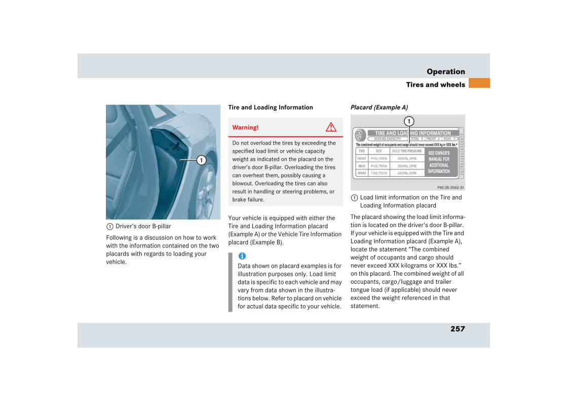
257
Operation
Tires and wheels
1 Driver’s door B-pillar
Following is a discussion on how to work with the information contained on the two placards with regards to loading your vehicle.
Tire and Loading Information
Your vehicle is equipped with either the Tire and Loading Information placard (Example A) or the Vehicle Tire Information placard (Example B).
Placard (Example A)
1 Load limit information on the Tire and Loading Information placard
The placard showing the load limit informa-tion is located on the driver's door B-pillar. If your vehicle is equipped with the Tire and Loading Information placard (Example A), locate the statement “The combined weight of occupants and cargo should never exceed XXX kilograms or XXX lbs.” on this placard. The combined weight of all occupants, cargo/luggage and trailer tongue load (if applicable) should never exceed the weight referenced in that statement.
Warning! G
Do not overload the tires by exceeding the specified load limit or vehicle capacity weight as indicated on the placard on the driver’s door B-pillar. Overloading the tires can overheat them, possibly causing a blowout. Overloading the tires can also result in handling or steering problems, or brake failure.
iData shown on placard examples is for illustration purposes only. Load limit data is specific to each vehicle and may vary from data shown in the illustra-tions below. Refer to placard on vehicle for actual data specific to your vehicle.
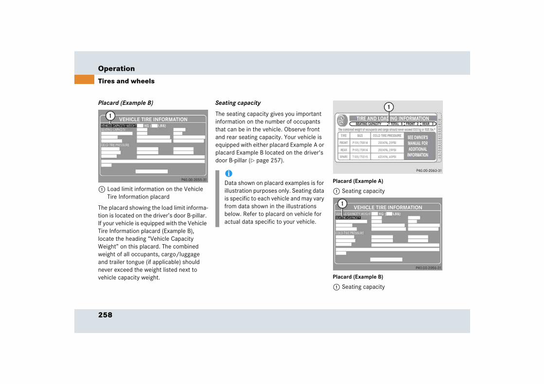
258
Operation
Tires and wheels
Placard (Example B)
1 Load limit information on the Vehicle Tire Information placard
The placard showing the load limit informa-tion is located on the driver’s door B-pillar. If your vehicle is equipped with the Vehicle Tire Information placard (Example B), locate the heading “Vehicle Capacity Weight” on this placard. The combined weight of all occupants, cargo/luggage and trailer tongue (if applicable) should never exceed the weight listed next to vehicle capacity weight.
Seating capacity
The seating capacity gives you important information on the number of occupants that can be in the vehicle. Observe front and rear seating capacity. Your vehicle is equipped with either placard Example A or placard Example B located on the driver's door B-pillar (� page 257).
Placard (Example A)
1 Seating capacity
Placard (Example B)
1 Seating capacity
iData shown on placard examples is for illustration purposes only. Seating data is specific to each vehicle and may vary from data shown in the illustrations below. Refer to placard on vehicle for actual data specific to your vehicle.

259
Operation
Tires and wheels
Steps for determining correct load limit
The following steps have been developed as required of all manufacturers under Title 49, Code of U.S. Federal Regulations, Part 575 pursuant to the “National Traffic and Motor Vehicle Safety Act of 1966”.
Step 1 (Vehicles equipped with placard Example A)
� Locate the statement “The combined weight of occupants and cargo should never exceed XXX kg or XXX lbs.” on your vehicle’s placard.
Step 1 (Vehicles equipped with placard Example B)
� Locate the heading “Vehicle Capacity Weight” on your vehicle’s placard.
Step 2
� Determine the combined weight of the driver and passengers that will be riding in your vehicle.
Step 3
� Subtract the combined weight of the driver and passengers from XXX kilo-grams or XXX lbs.
Step 4
� The resulting figure equals the avail-able amount of cargo and luggage load capacity. For example, if the “XXX” amount equals 1400 lbs. and there will be five 150 lbs. passengers in your vehicle, the amount of available cargo and luggage load capacity is 650 lbs. (1400-750 (5 x150) = 650 lbs.)
Step 5
� Determine the combined weight of luggage and cargo being loaded on the vehicle. That weight may not safely exceed the available cargo and luggage load capacity calculated in step 4.
Step 6 (if applicable)
� If your vehicle will be towing a trailer, load from your trailer will be trans-ferred to your vehicle. Consult this manual to determine how this reduces the available cargo and luggage load capacity of your vehicle (� page 261).
The following table shows examples on how to calculate total and cargo load capacities with varying seating configura-tions and number and size of occupants. The following examples use a load limit of 1500 lbs. This is for illustration purposes only. Make sure you are using the actual load limit for your vehicle stated on the vehicle’s placard (� page 257).
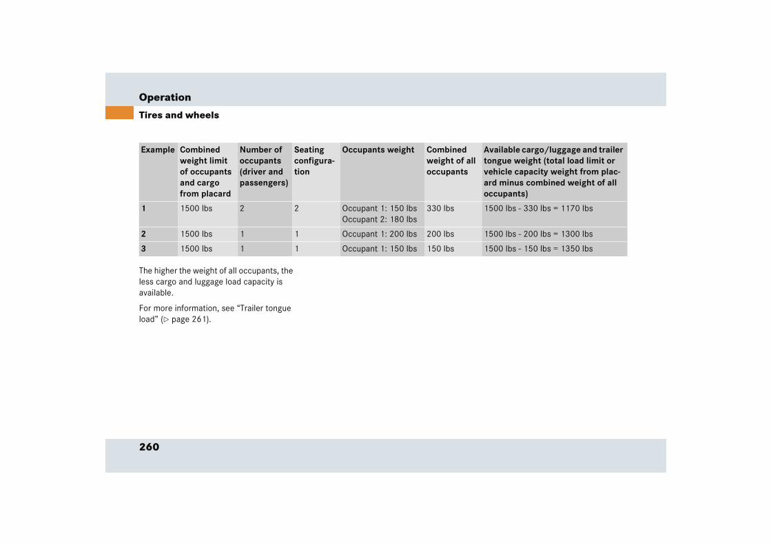
260
Operation
Tires and wheels
The higher the weight of all occupants, the less cargo and luggage load capacity is available.
For more information, see “Trailer tongue load” (� page 261).
Example Combined weight limit of occupants and cargo from placard
Number of occupants (driver and passengers)
Seating configura-tion
Occupants weight Combined weight of all occupants
Available cargo/luggage and trailer tongue weight (total load limit or vehicle capacity weight from plac-ard minus combined weight of all occupants)
1 1500 lbs 2 2 Occupant 1: 150 lbsOccupant 2: 180 lbs
330 lbs 1500 lbs - 330 lbs = 1170 lbs
2 1500 lbs 1 1 Occupant 1: 200 lbs 200 lbs 1500 lbs - 200 lbs = 1300 lbs
3 1500 lbs 1 1 Occupant 1: 150 lbs 150 lbs 1500 lbs - 150 lbs = 1350 lbs

261
Operation
Tires and wheels
Certification label
Even after careful determination of the combined weight of all occupants, cargo and the trailer tongue load (if applicable) (� page 261) as to not exceed the permis-sible load limit, you must make sure that your vehicle never exceeds the Gross Vehi-cle Weight Rating (GVWR) and the Gross Axle Weight Rating (GAWR) for either the front or rear axle. You can obtain the GVWR and GAWR from the Certification la-bel. The Certification Label can be found on the driver’s door B-pillar, see “Technical data” (� page 366).
Gross Vehicle Weight Rating (GVWR): The total weight of the vehicle, all occupants, all cargo, and the trailer tongue load (� page 261) must never exceed the GVWR.
Gross Axle Weight Rating (GAWR): The to-tal allowable weight that can be carried by a single axle (front or rear).
To assure that your vehicle does not ex-ceed the maximum permissible weight limits (GVWR and GAWR for front and rear axle), have the loaded vehicle (including driver, passengers and all cargo and, if ap-plicable, trailer fully loaded) weighed on a suitable commercial scale.
Trailer tongue load
The tongue load of any trailer is an impor-tant weight to measure because it affects the load you can carry in your vehicle. If a trailer is towed, the tongue load must be added to the weight of all occupants riding and any cargo you are carrying in the vehicle. The tongue load typically is ten percent of the trailer weight and every-thing loaded in it.
Your Mercedes-Benz has been designed primarily to carry passengers and their cargo. Mercedes-Benz does not recom-mend trailer towing with your vehicle.
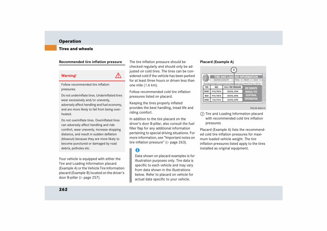
262
Operation
Tires and wheels
Recommended tire inflation pressure
Your vehicle is equipped with either the Tire and Loading Information placard (Example A) or the Vehicle Tire Information placard (Example B) located on the driver's door B-pillar (� page 257).
The tire inflation pressure should be checked regularly and should only be ad-justed on cold tires. The tires can be con-sidered cold if the vehicle has been parked for at least three hours or driven less than one mile (1.6 km).
Follow recommended cold tire inflation pressures listed on placard.
Keeping the tires properly inflated provides the best handling, tread life and riding comfort.
In addition to the tire placard on the driver’s door B-pillar, also consult the fuel filler flap for any additional information pertaining to special driving situations. For more information, see “Important notes on tire inflation pressure” (� page 263).
Placard (Example A)
1 Tire and Loading Information placard with recommended cold tire inflation pressures
Placard (Example A) lists the recommend-ed cold tire inflation pressures for maxi-mum loaded vehicle weight. The tire inflation pressures listed apply to the tires installed as original equipment.
Warning! G
Follow recommended tire inflation pressures.
Do not underinflate tires. Underinflated tires wear excessively and/or unevenly, adversely affect handling and fuel economy, and are more likely to fail from being over-heated.
Do not overinflate tires. Overinflated tires can adversely affect handling and ride comfort, wear unevenly, increase stopping distance, and result in sudden deflation (blowout) because they are more likely to become punctured or damaged by road debris, potholes etc. i
Data shown on placard examples is for illustration purposes only. Tire data is specific to each vehicle and may vary from data shown in the illustrations below. Refer to placard on vehicle for actual data specific to your vehicle.
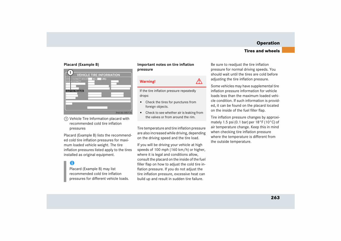
263
Operation
Tires and wheels
Placard (Example B)
1 Vehicle Tire Information placard with recommended cold tire inflation pressures
Placard (Example B) lists the recommend-ed cold tire inflation pressures for maxi-mum loaded vehicle weight. The tire inflation pressures listed apply to the tires installed as original equipment.
Important notes on tire inflation pressure
Tire temperature and tire inflation pressure are also increased while driving, depending on the driving speed and the tire load.
If you will be driving your vehicle at high speeds of 100 mph (160 km/h) or higher, where it is legal and conditions allow, consult the placard on the inside of the fuel filler flap on how to adjust the cold tire in-flation pressure. If you do not adjust the tire inflation pressure, excessive heat can build up and result in sudden tire failure.
Be sure to readjust the tire inflation pressure for normal driving speeds. You should wait until the tires are cold before adjusting the tire inflation pressure.
Some vehicles may have supplemental tire inflation pressure information for vehicle loads less than the maximum loaded vehi-cle condition. If such information is provid-ed, it can be found on the placard located on the inside of the fuel filler flap.
Tire inflation pressure changes by approxi-mately 1.5 psi (0.1 bar) per 18°F (10°C) of air temperature change. Keep this in mind when checking tire inflation pressure where the temperature is different from the outside temperature.
iPlacard (Example B) may list recommended cold tire inflation pressures for different vehicle loads.
Warning! G
If the tire inflation pressure repeatedly drops:
� Check the tires for punctures from foreign objects.
� Check to see whether air is leaking from the valves or from around the rim.

264
Operation
Tires and wheels
Checking tire inflation pressure
Regularly check your tire inflation pressure at least once a month.
Check and adjust the tire inflation pressure when the tires are cold. The tires can be considered cold if the vehicle has been parked for at least three hours or driven less than one mile (1.6 km).
If you check the tire inflation pressure when the tires are warm (the vehicle has been driven for several miles or sitting less than three hours), the reading will be approximately 4 psi (0.3 bar) higher than the cold reading. This is normal. Do not let air out to match the specified cold tire in-flation pressure. Otherwise the tire will be underinflated.
Checking tire inflation pressure manually
Follow the steps below to achieve correct tire inflation pressure:
� Remove the cap from the valve on one tire.
� Firmly press a tire gauge onto the valve.
� Read tire inflation pressure on tire gauge and check against the recom-mended tire inflation pressure on the placard on the driver’s door B-pillar (� page 262). If necessary, add air to achieve the recommended tire inflation pressure.
� Install the valve cap.
� Repeat this procedure for each tire.
iIf you have overfilled the tire, release tire inflation pressure by pushing the metal stem of the valve with e.g. a tip of a pen. Then recheck the tire inflation pressure with the tire gauge.

265
Operation
Tires and wheels
Checking tire inflation pressure electronically
The tire inflation pressure monitor only functions on wheels that are equipped with the proper electronic sensors. It monitors the tire inflation pressure, as selected by the driver, in all four tires. A warning is is-sued to alert you to a decrease in pressure in one or more of the tires.
Tire inflation pressure inquiries are made using the multifunction display (� page 117). The present inflation pres-sures are displayed only after a few min-utes travel time.
� Switch on the ignition (� page 40).
� Make sure you are viewing the stan-dard display menu (� page 117).
� Press k button until the current in-flation pressures for each tire appear in the tachometer display field.
iPossible differences between the read-ings of a tire inflation pressure gauge of an air hose, e.g. gas station equipment, and the vehicle’s control system can occur. The readings issued by the con-trol system are more precise.
iYou can select the unit of measure (bar/psi) used for the tire inflation pressure by changing the setting in the control system (� page 136).
Warning! G
When the tire inflation pressure monitoring system warning light is lit, one or more of your tires is significantly under-inflated. You should stop and check your tires as soon as possible, and inflate them to the proper tire inflation pressure as indicated on the vehi-cle’s tire information placard. Driving on a significantly under-inflated tire causes the tire to overheat and can lead to tire failure. Under-inflation also reduces fuel efficiency and tire tread life, and may affect the vehi-cle’s handling and stopping ability. Each tire, including the spare, should be checked monthly when cold and set to the recom-mended tire inflation pressure as specified in the vehicle placard and owner’s manual. ��
266
Operation
Tires and wheels
Activating the tire inflation pressure monitor
You must activate the tire inflation pres-sure monitor in the following cases:
� if you have changed the tire inflation pressure
� if you have replaced the wheels or tires
� if you have installed new wheels or tires
� Make sure the tire inflation pressure is set correctly.
� Press the k button on the multi-function steering wheel until the infla-tion pressure of each tire appears in the right display field.
iThe recommended tire inflation pres-sures for your vehicle can be found on the tire placard located on the driver’s door B-pillar. The tire inflation pres-sures are not listed in the owner’s man-ual.
Warning! G
The tire inflation pressure monitor does not indicate a warning for wrongly selected tire inflation pressures. Always adjust tire infla-tion pressure according to the placard on the driver’s door B-pillar or, if available, the inside of the fuel filler flap.
The tire inflation pressure monitor is not able to issue a warning due to a sudden dra-matic loss of tire inflation pressure (e.g. tire blowout caused by a foreign object). In this case bring the vehicle to a halt by carefully applying the brakes and avoiding abrupt steering maneuvers.
iOperating radio transmission equip-ment (e.g. wireless headsets, two-way radios) in or near the vehicle could cause the tire inflation pressure moni-tor to malfunction.
Warning! G
Follow recommend tire inflation pressures.
Do not underinflate tires. Underinflated tires wear excessively and/or unevenly, adversely affect handling and fuel economy, and are more likely to fail from being over-heated.
Do not overinflate tires. Overinflated tires can adversely affect handling and ride comfort, wear unevenly, increase stopping distance, and result in sudden deflation (blowout) because they are more likely to become punctured or damaged by road debris, potholes etc.
Do not overload the tires by exceeding the specified load limit or vehicle capacity weight as indicated on the placard on the driver’s door B-pillar. Overloading the tires can overheat them, possibly causing a blowout.
��
267
Operation
Tires and wheels
� Press the reset button (� page 29).
The following message will appear in the speedometer display field: Monitor current tire pressure?
� Press æ button.
The following message will appear in the speedometer display field:Tire pressure displayedafterdriving a few mins.Reactivate w/R-button
If you wish to cancel activation:
� Press ç button.
If the following message appears in the speedometer display field:Reactivate tire press. monit.
� Re-start the activation of the tire infla-tion pressure monitor.
If the following message appears in the speedometer display field:Tire pressure Check tires!
� Re-start the activation of the tire infla-tion pressure monitor.
Potential problems associated with underinflated and overinflated tires
Underinflated tire inflation pressure
Underinflated tires can:
� cause excessive and uneven tire wear
� adversely affect fuel economy
� lead to tire failure from being overheated
� adversely affect handling characteristics
iIf transporting a deflated road wheel or additional wheel sensors in the vehicle, the tire inflation pressure monitor should not be reactivated until the de-flated wheel or additional wheel sen-sors have been removed from the vehicle. Otherwise the deflated wheel or additional sensors could confuse the tire inflation pressure monitor system and cause it to malfunction.
Warning! G
Follow recommended tire inflation pressures.
Do not underinflate tires. Underinflated tires wear excessively and/or unevenly, adversely affect handling and fuel economy, and are more likely to fail from being overheated.
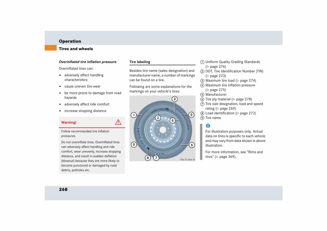
268
Operation
Tires and wheels
Overinflated tire inflation pressure
Overinflated tires can:
� adversely affect handling characteristics
� cause uneven tire wear
� be more prone to damage from road hazards
� adversely affect ride comfort
� increase stopping distance
Tire labeling
Besides tire name (sales designation) and manufacturer name, a number of markings can be found on a tire.
Following are some explanations for the markings on your vehicle's tires:
1 Uniform Quality Grading Standards (� page 276)
2 DOT, Tire Identification Number (TIN) (� page 273)
3 Maximum tire load (� page 274)4 Maximum tire inflation pressure
(� page 275)5 Manufacturer6 Tire ply material (� page 278)7 Tire size designation, load and speed
rating (� page 269)8 Load identification (� page 272)9 Tire name
Warning! G
Follow recommended tire inflation pressures.
Do not overinflate tires. Overinflated tires can adversely affect handling and ride comfort, wear unevenly, increase stopping distance, and result in sudden deflation (blowout) because they are more likely to become punctured or damaged by road debris, potholes etc.
iFor illustration purposes only. Actual data on tires is specific to each vehicle and may vary from data shown in above illustration.
For more information, see “Rims and tires” (� page 369).
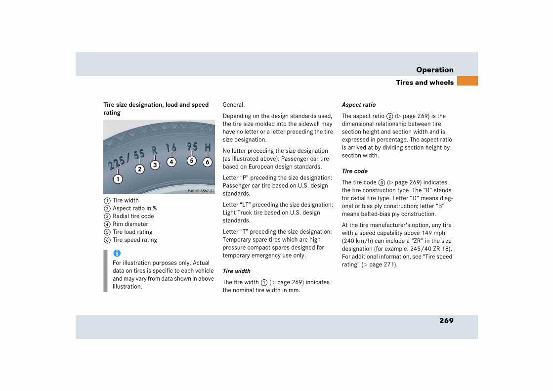
269
Operation
Tires and wheels
Tire size designation, load and speed rating
1 Tire width 2 Aspect ratio in %3 Radial tire code4 Rim diameter5 Tire load rating6 Tire speed rating
General:
Depending on the design standards used, the tire size molded into the sidewall may have no letter or a letter preceding the tire size designation.
No letter preceding the size designation (as illustrated above): Passenger car tire based on European design standards.
Letter “P” preceding the size designation: Passenger car tire based on U.S. design standards.
Letter “LT” preceding the size designation: Light Truck tire based on U.S. design standards.
Letter “T” preceding the size designation: Temporary spare tires which are high pressure compact spares designed for temporary emergency use only.
Tire width
The tire width 1 (� page 269) indicates the nominal tire width in mm.
Aspect ratio
The aspect ratio 2 (� page 269) is the dimensional relationship between tire section height and section width and is expressed in percentage. The aspect ratio is arrived at by dividing section height by section width.
Tire code
The tire code 3 (� page 269) indicates the tire construction type. The “R” stands for radial tire type. Letter “D” means diag-onal or bias ply construction; letter “B” means belted-bias ply construction.
At the tire manufacturer's option, any tire with a speed capability above 149 mph (240 km/h) can include a “ZR” in the size designation (for example: 245/40 ZR 18). For additional information, see “Tire speed rating” (� page 271).
iFor illustration purposes only. Actual data on tires is specific to each vehicle and may vary from data shown in above illustration.
270
Operation
Tires and wheels
Rim diameter
The rim diameter 4 (� page 269) is the diameter of the bead seat, not the diameter of the rim edge. Rim diameter is indicated in inches (in).
Tire load rating
The tire load rating 5 (� page 269) is a numerical code associated with the maximum load a tire can support.
For example, a load rating of 91 corre-sponds to a maximum load of 1356 lbs (615 kg) the tire is designed to support. See also “Maximum tire load” (� page 274) where the maximum load as-sociated with the load index is indicated in kilograms and lbs.
For additional information on tire load rating, see “Load identification” (� page 272).
Warning G
The tire load rating must always be at least half of the GAWR (� page 279) of your vehi-cle. Otherwise tire failure may be the result which may cause an accident and/or seri-ous personal injury to you or others.
Always replace rims and tires with the same designation, manufacturer and type as shown on the original part.
Warning! G
Do not overload the tires by exceeding the specified load limit or vehicle capacity weight as indicated on the placard located on the driver's door B-pillar. Overloading the tires can overheat them, possibly causing a blowout. Overloading the tires can also result in handling or steering problems, or brake failure.
iTire load rating 5 (� page 269) and Tire speed rating 6 (� page 269) are also referred to as “service descrip-tion”.
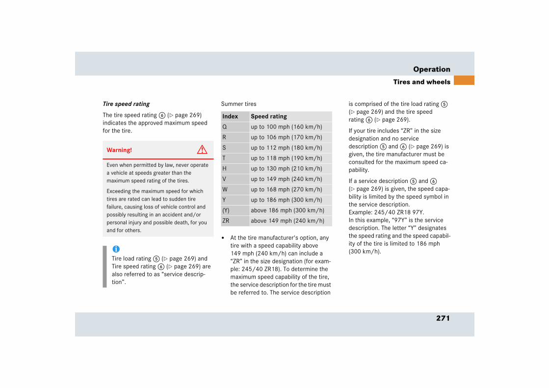
271
Operation
Tires and wheels
Tire speed rating
The tire speed rating 6 (� page 269) indicates the approved maximum speed for the tire.
Summer tires
� At the tire manufacturer's option, any tire with a speed capability above 149 mph (240 km/h) can include a “ZR” in the size designation (for exam-ple: 245/40 ZR18). To determine the maximum speed capability of the tire, the service description for the tire must be referred to. The service description
is comprised of the tire load rating 5 (� page 269) and the tire speed rating 6 (� page 269).
If your tire includes “ZR” in the size designation and no service description 5 and 6 (� page 269) is given, the tire manufacturer must be consulted for the maximum speed ca-pability.
If a service description 5 and 6 (� page 269) is given, the speed capa-bility is limited by the speed symbol in the service description. Example: 245/40 ZR18 97Y. In this example, “97Y” is the service description. The letter “Y” designates the speed rating and the speed capabil-ity of the tire is limited to 186 mph (300 km/h).
Warning! G
Even when permitted by law, never operate a vehicle at speeds greater than the maximum speed rating of the tires.
Exceeding the maximum speed for which tires are rated can lead to sudden tire failure, causing loss of vehicle control and possibly resulting in an accident and/or personal injury and possible death, for you and for others.
iTire load rating 5 (� page 269) and Tire speed rating 6 (� page 269) are also referred to as “service descrip-tion”.
Index Speed rating
Q up to 100 mph (160 km/h)
R up to 106 mph (170 km/h)
S up to 112 mph (180 km/h)
T up to 118 mph (190 km/h)
H up to 130 mph (210 km/h)
V up to 149 mph (240 km/h)
W up to 168 mph (270 km/h)
Y up to 186 mph (300 km/h)
(Y) above 186 mph (300 km/h)
ZR above 149 mph (240 km/h)
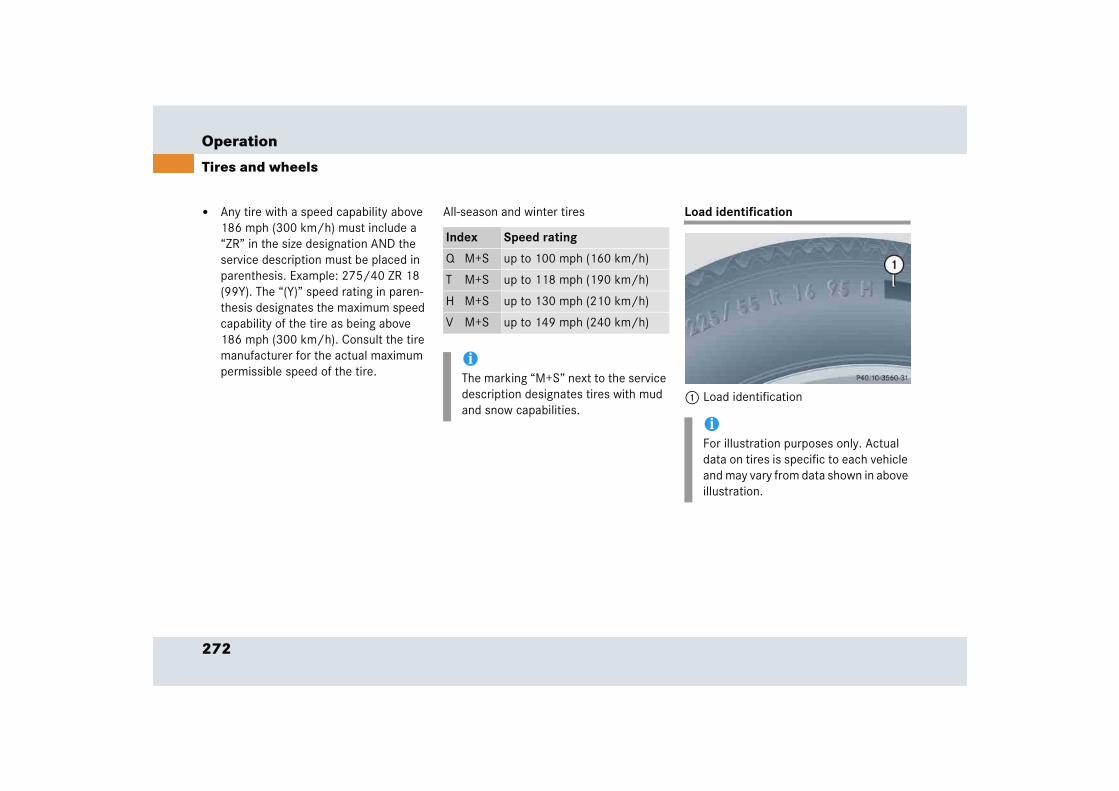
272
Operation
Tires and wheels
� Any tire with a speed capability above 186 mph (300 km/h) must include a “ZR” in the size designation AND the service description must be placed in parenthesis. Example: 275/40 ZR 18 (99Y). The “(Y)” speed rating in paren-thesis designates the maximum speed capability of the tire as being above 186 mph (300 km/h). Consult the tire manufacturer for the actual maximum permissible speed of the tire.
All-season and winter tires Load identification
1 Load identification
Index Speed rating
Q M+S up to 100 mph (160 km/h)
T M+S up to 118 mph (190 km/h)
H M+S up to 130 mph (210 km/h)
V M+S up to 149 mph (240 km/h)
iThe marking “M+S” next to the service description designates tires with mud and snow capabilities.
iFor illustration purposes only. Actual data on tires is specific to each vehicle and may vary from data shown in above illustration.
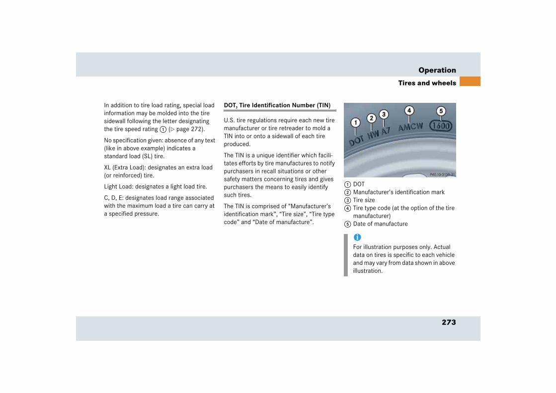
273
Operation
Tires and wheels
In addition to tire load rating, special load information may be molded into the tire sidewall following the letter designating the tire speed rating 1 (� page 272).
No specification given: absence of any text (like in above example) indicates a standard load (SL) tire.
XL (Extra Load): designates an extra load (or reinforced) tire.
Light Load: designates a light load tire.
C, D, E: designates load range associated with the maximum load a tire can carry at a specified pressure.
DOT, Tire Identification Number (TIN)
U.S. tire regulations require each new tire manufacturer or tire retreader to mold a TIN into or onto a sidewall of each tire produced.
The TIN is a unique identifier which facili-tates efforts by tire manufactures to notify purchasers in recall situations or other safety matters concerning tires and gives purchasers the means to easily identify such tires.
The TIN is comprised of “Manufacturer’s identification mark”, “Tire size”, “Tire type code” and “Date of manufacture”.
1 DOT 2 Manufacturer’s identification mark3 Tire size4 Tire type code (at the option of the tire
manufacturer)5 Date of manufacture
iFor illustration purposes only. Actual data on tires is specific to each vehicle and may vary from data shown in above illustration.

274
Operation
Tires and wheels
DOT (Department of Transportation)
A tire branding symbol 1 (� page 273) which denotes the tire meets require-ments of the U.S. Department of Transpor-tation.
Manufacturer’s identification mark
The manufacturer’s identification mark 2 (� page 273) denotes the tire manufacturer.
New tires have a mark with two symbols.
Retreaded tires have a mark with four sym-bols. For more information on retreaded tires, see (� page 253).
Tire size
The code 3 (� page 273) indicates the tire size.
Tire type code
The code 4 (� page 273) may, at the option of the manufacturer, be used as a descriptive code for identifying significant characteristics of the tire.
Date of manufacture
The date of manufacture 5 (� page 273) identifies the week and year of manufac-ture.
The first two figures identify the week, starting with “01” to represent the first full week of the calendar year. The second two figures represent the year.
For example, “3202” represents the 32nd week of 2002.
Maximum tire load
1 Maximum tire load rating
The maximum tire load is the maximum weight the tires are designed to support.
iFor illustration purposes only. Actual data on tires is specific to each vehicle and may vary from data shown in above illustration.
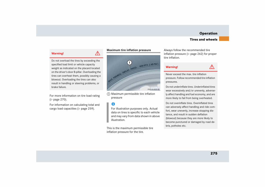
275
Operation
Tires and wheels
For more information on tire load rating (� page 270).
For information on calculating total and cargo load capacities (� page 259).
Maximum tire inflation pressure
1 Maximum permissible tire inflation pressure
This is the maximum permissible tire inflation pressure for the tire.
Always follow the recommended tire inflation pressure (� page 262) for proper tire inflation.
Warning! G
Do not overload the tires by exceeding the specified load limit or vehicle capacity weight as indicated on the placard located on the driver’s door B-pillar. Overloading the tires can overheat them, possibly causing a blowout. Overloading the tires can also result in handling or steering problems, or brake failure.
iFor illustration purposes only. Actual data on tires is specific to each vehicle and may vary from data shown in above illustration.
Warning! G
Never exceed the max. tire inflation pressure. Follow recommended tire inflation pressures.
Do not underinflate tires. Underinflated tires wear excessively and/or unevenly, adverse-ly affect handling and fuel economy, and are more likely to fail from being overheated.
Do not overinflate tires. Overinflated tires can adversely affect handling and ride com-fort, wear unevenly, increase stopping dis-tance, and result in sudden deflation (blowout) because they are more likely to become punctured or damaged by road de-bris, potholes etc.
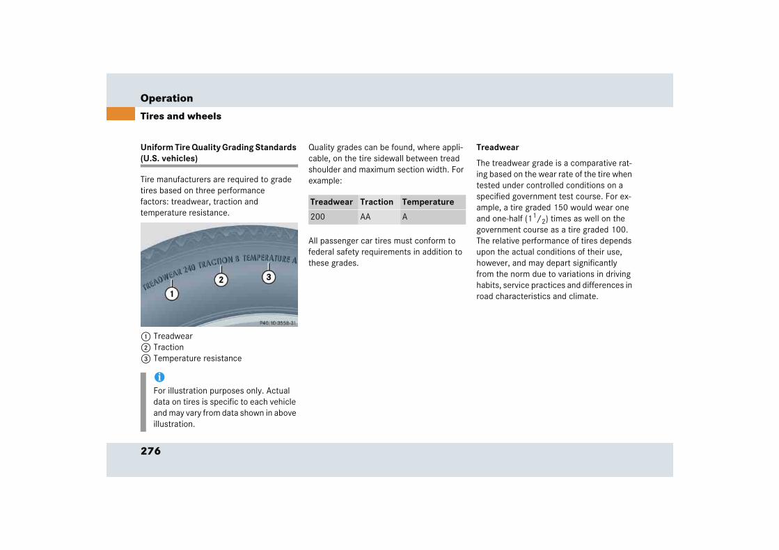
276
Operation
Tires and wheels
Uniform Tire Quality Grading Standards (U.S. vehicles)
Tire manufacturers are required to grade tires based on three performance factors: treadwear, traction and temperature resistance.
1 Treadwear2 Traction3 Temperature resistance
Quality grades can be found, where appli-cable, on the tire sidewall between tread shoulder and maximum section width. For example:
All passenger car tires must conform to federal safety requirements in addition to these grades.
Treadwear
The treadwear grade is a comparative rat-ing based on the wear rate of the tire when tested under controlled conditions on a specified government test course. For ex-ample, a tire graded 150 would wear one and one-half (11/2) times as well on the government course as a tire graded 100. The relative performance of tires depends upon the actual conditions of their use, however, and may depart significantly from the norm due to variations in driving habits, service practices and differences in road characteristics and climate.
iFor illustration purposes only. Actual data on tires is specific to each vehicle and may vary from data shown in above illustration.
Treadwear Traction Temperature
200 AA A
277
Operation
Tires and wheels
Traction
The traction grades, from highest to low-est, are AA, A, B, and C. Those grades rep-resent the tire’s ability to stop on wet pavement as measured under controlled conditions on specified government test surfaces of asphalt and concrete. A tire marked C may have poor traction perfor-mance.
Temperature
The temperature grades are A (the high-est), B, and C, representing the tire’s resis-tance to the generation of heat and its ability to dissipate heat when tested under controlled conditions on a specified indoor laboratory test wheel. Sustained high tem-perature can cause the material of the tire to degenerate and reduce tire life, and ex-cessive temperature can lead to sudden tire failure. The grade C corresponds to a level of performance which all passenger car tires must meet under the Federal Mo-tor Vehicle Safety Standard No. 109. Grades B and A represent higher levels of performance on the laboratory test wheel than the minimum required by law.
Warning! G
The traction grade assigned to this tire is based on straight-ahead braking traction tests, and does not include acceleration, cornering, hydroplaning, or peak traction characteristics.
Warning! G
The temperature grade for this tire is established for a tire that is properly inflated and not overloaded. Excessive speed, underinflation, or excessive loading, either separately or in combination, can cause excessive heat build-up and possible tire failure.

278
Operation
Tires and wheels
Tire ply material
1 Plies in sidewall2 Plies under tread
This marking tells you about the type of cord and number of plies in the sidewall and under the tread.
Tire and loading terminology
Accessory weight
The combined weight (in excess of those standard items which may be replaced) of automatic transmission, power steering, power brakes, power windows, power seats, radio, and heater, to the extent that these items are available as factory-installed equipment (whether installed or not).
Air pressure
The amount of air inside the tire pressing outward on each square inch of the tire. Air pressure is expressed in pounds per square inch (psi), or kilopascal (kPa) or bars.
Aspect ratio
Dimensional relationship between tire section height and section width expressed in percentage.
Bar
Another metric unit for air pressure. There are 14.5038 pounds per square inch (psi) to 1 bar; there are 100 kilopascals (kPa) to 1 bar.
Bead
The tire bead contains steel wires wrapped by steel cords that hold the tire onto the rim.
Cold tire inflation pressure
Tire inflation pressure when your vehicle has been sitting for at least three hours or driven no more than one mile (1.6 km).
Curb weight
The weight of a motor vehicle with stan-dard equipment including the maximum capacity of fuel, oil, and coolant, and, if so equipped, air conditioning and additional optional equipment, but without passen-gers and cargo.
iFor illustration purposes only. Actual data on tires is specific to each vehicle and may vary from data shown in above illustration.
279
Operation
Tires and wheels
DOT (Department of Transportation)
A tire branding symbol which denotes the tire meets requirements of the U.S. Department of Transportation.
GAWR (Gross Axle Weight Rating)
The GAWR is the maximum permissible axle weight. The gross vehicle weight on each axle must never exceed the GAWR for the front and rear axle indicated on the Certification label located on the driver's door B-pillar.
GVW (Gross Vehicle Weight)
The GVW comprises the weight of the vehicle including fuel, tools, spare wheel, installed accessories, passengers and cargo and, if applicable, trailer tongue load. The GWV must never exceed the GWVR indicated on the Certification label located on the driver's door B-pillar.
GVWR (Gross Vehicle Weight Rating)
This is the maximum permissible vehicle weight of the fully loaded vehicle (weight of the vehicle including all options, passen-gers, fuel, and cargo and, if applicable, trailer tongue load). It is indicated on Certification label located on the driver's door B-pillar.
Kilopascal (kPa)
The metric unit for air pressure. There are 6.9 kPa to one psi; another metric unit for air pressure is bars. There are 100 kilopascals (kPa) to one bar.
Maximum load rating
The maximum load in kilograms and pounds that can be carried by the tire.
Maximum loaded vehicle weight
The sum of curb weight, accessory weight, vehicle capacity weight and production options weight.
Maximum tire inflation pressure
This number is the greatest amount of air pressure that should ever be put in the tire under normal driving conditions.
Normal occupant weight
The number of occupants the vehicle is designed to seat, multiplied by 68 kilograms (150 lbs).
Occupant distribution
The distribution of occupants in a vehicle at their designated seating positions.
Production options weight
The combined weight of those installed regular production options weighing over 5 lbs (2.3 kilograms) in excess of those standard items which they replace, not previously considered in curb weight or accessory weight, including heavy duty brakes, ride levelers, roof rack, heavy duty battery, and special trim.
280
Operation
Tires and wheels
PSI (Pounds per square inch)
A standard unit of measure for air pressure -> bar, kilopascal (kPa).
Recommended tire inflation pressure
Recommended tire inflation pressure listed on placard located on driver's door B-pillar for normal driving conditions. Provides best handling, tread life and riding comfort.
Rim
A metal support for a tire or a tire and tube assembly upon which the tire beads are seated.
Sidewall
The portion of a tire between the tread and the bead.
TIN (Tire Identification Number)
Unique identifier which facilitates efforts by tire manufacturers to notify purchasers in recall situations or other safety matters concerning tires and gives purchases the means to easily identify such tires. The TIN is comprised of “Manufacturer's identifica-tion mark”, “Tire size”, “Tire type code” and “Date of manufacture”.
Tire load rating
Numerical code associated with the maximum load a tire can support.
Tire ply composition and material used
This indicates the number of plies or the number of layers of rubber-coated fabric in the tire tread and sidewall. Tire manufac-turers also must indicate the ply materials in the tire and sidewall, which include steel, nylon, polyester, and others.
Tire speed rating
Part of tire designation; indicates the speed range for which a tire is approved.
Traction
Force exerted by the vehicle on the road via the tires. The amount of grip provided.
Tread
The portion of a tire that comes into contact with the road.
Treadwear indicators
Narrow bands, sometimes called “wear bars” that show across the tread of a tire when only 1/6 in (1.6 mm) of tread remains.
281
Operation
Tires and wheels
Uniform Tire Quality Grading Standards
A tire information system that provides consumers with ratings for a tire’s traction, temperature and treadwear. Ratings are determined by tire manufacturers using government testing procedures. The ratings are molded into the sidewall of the tire.
Vehicle capacity weight
Rated cargo and luggage load plus 68 kilograms (150 lbs) times the vehicle’s designated seating capacity.
Vehicle maximum load on the tire
Load on an individual tire that is determined by distributing to each axle its share of the maximum loaded vehicle weight and dividing it by two.
Rotating tires
Tire rotation can be performed on vehicles with tires of the same dimension all around. If your vehicle is equipped with tires of the same dimension all around, tires can be rotated, observing a
front-to-rear rotation pattern that will maintain the intended rotation (spinning) direction of the tire (� page 256).
In some cases, such as when your vehicle is equipped with mixed-size tires (different tire dimension front vs. rear), tire rotation is not possible.
If applicable to your vehicle's tire configu-ration, tires can be rotated according to the tire manufacturer's recommended in-tervals in the tire manufacturer's warranty pamphlet located in your vehicle literature portfolio. If none is available, tires should be rotated every 3000 to 6000 miles (5000 to 10000 km), or sooner if neces-sary, according to the degree of tire wear. The same rotation (spinning) direction must be maintained (� page 256).
Rotate tires before the characteristic tire wear pattern becomes visible (shoulder wear on front tires and tread center wear on rear tires).
!A wheel change should only be carried out at an authorized Mercedes-Benz Center. Otherwise there is a danger of damaging the vehicle by jacking it up incorrectly.
Warning! G
Rotate front and rear wheels only if the tires are of the same dimension.
If your vehicle is equipped with mixed-size tires (different tire dimensions front vs. rear), tire rotation is not possible.
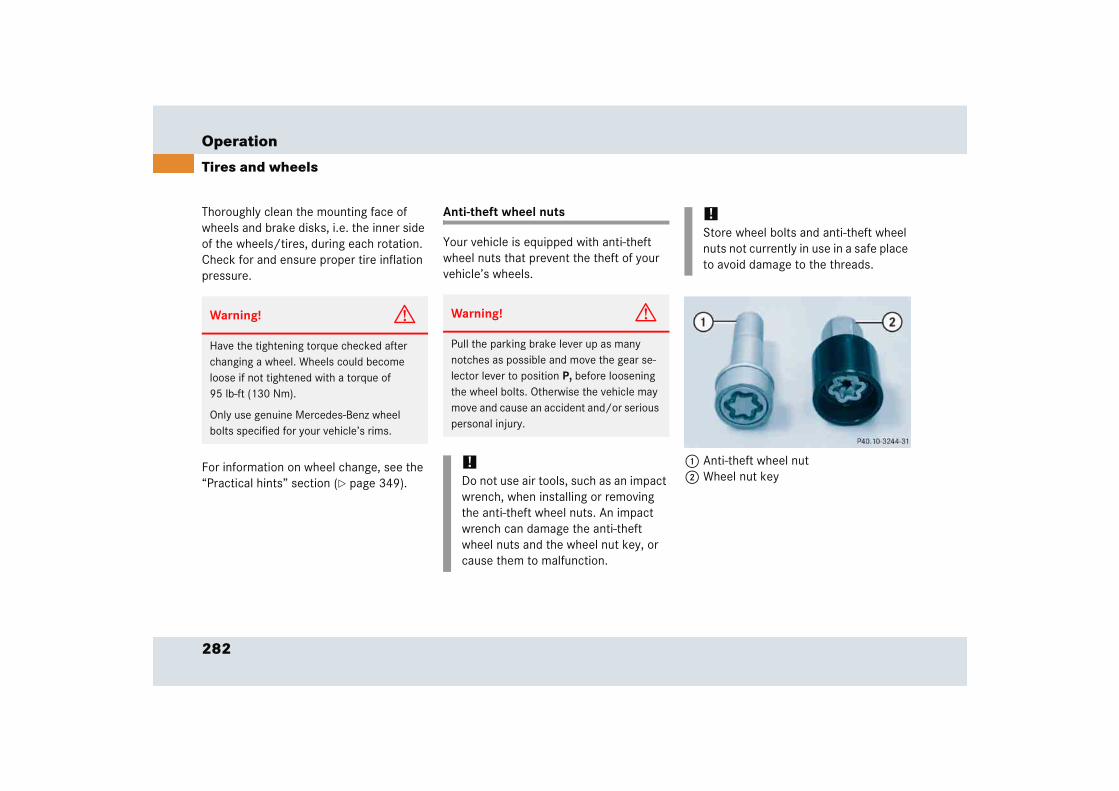
282
Operation
Tires and wheels
Thoroughly clean the mounting face of wheels and brake disks, i.e. the inner side of the wheels/tires, during each rotation. Check for and ensure proper tire inflation pressure.
For information on wheel change, see the “Practical hints” section (� page 349).
Anti-theft wheel nuts
Your vehicle is equipped with anti-theft wheel nuts that prevent the theft of your vehicle’s wheels.
1 Anti-theft wheel nut2 Wheel nut key
Warning! G
Have the tightening torque checked after changing a wheel. Wheels could become loose if not tightened with a torque of 95 lb-ft (130 Nm).
Only use genuine Mercedes-Benz wheel bolts specified for your vehicle’s rims.
Warning! G
Pull the parking brake lever up as many notches as possible and move the gear se-lector lever to position P, before loosening the wheel bolts. Otherwise the vehicle may move and cause an accident and/or serious personal injury.
!Do not use air tools, such as an impact wrench, when installing or removing the anti-theft wheel nuts. An impact wrench can damage the anti-theft wheel nuts and the wheel nut key, or cause them to malfunction.
!Store wheel bolts and anti-theft wheel nuts not currently in use in a safe place to avoid damage to the threads.
283
Operation
Tires and wheels
Removing anti-theft wheel nuts
� Unscrew anti-theft wheel nut 1 using wheel nut key 2.
� Replace anti-theft wheel nut 1 with one of the regular wheel bolts.
� Fasten the wheel bolt and tighten it with a torque wrench to a tightening torque of 95 lb-ft (130 Nm).
Fitting anti-theft wheel nuts
� Unscrew a wheel bolt from one of the wheels.
� Replace that wheel bolt with one of the anti-theft wheel nuts 1 delivered with your vehicle.
� Fasten anti-theft wheel nut 1 using wheel nut key 2 and tighten with a torque wrench to a tightening torque of 95 lb-ft (130 Nm).Warning! G
The wheels could come loose if the wheel bolts are not tightened to a torque of 95 lb-ft (130 Nm). Have the tightening torque checked after changing a wheel.
Warning! G
The wheels could come loose if the wheel bolts are not tightened to a torque of 95 lb-ft (130 Nm). Have the tightening torque checked after changing a wheel.
iKeep the anti-theft wheel nut key in a convenient place in your vehicle where you and service personnel can always find it easily when it is needed.
iIf you should lose the anti-theft wheel nut key or one of the anti-theft wheel nuts, please contact an authorized Mercedes-Benz Center for a replace-ment.
284
Operation
Winter driving
Before the onset of winter, have your vehicle winterized at an authorized Mercedes-Benz Center. This service includes:
� Check of anticorrosion and antifreeze concentration.
� Addition of cleaning concentrate to the water of the windshield and headlamp cleaning system. Add MB Concentrate “S” to a premixed windshield washer solvent/antifreeze which is formulated for below freezing temperatures (� page 382).
� Battery test. Battery capacity drops with decreasing ambient temperature. A well charged battery helps to make sure that the engine can be started, even at low ambient temperatures.
� Tire change. Mercedes-Benz recom-mends M+S rated radial-ply tires with a minimum tread depth of approximately 1/6 in (4 mm) on all four wheels for the winter season.
Winter tires*
Always use winter tires at temperatures below 45°F (7°C) and whenever wintry road conditions prevail. Use of winter tires is the only way to achieve the maximum effectiveness of the ABS and ESP in winter operation.
For safe handling, make sure that all mounted winter tires are of the same make and have the same tread design.
Always observe the speed rating of the winter tires installed on your vehicle. If the maximum speed for which your tires are rated is below the speed rating of your vehicle, you must place a notice to this effect where it will be seen by the driver. Such notices are available from your tire dealer or from any authorized Mercedes-Benz Center.
!A wheel change should only be carried out at an authorized Mercedes-Benz Center. Otherwise there is a danger of damaging the vehicle by jacking it up incorrectly.
Warning! G
Winter tires with a tread depth under 1/6 in (4 mm) must be replaced. They are no longer suitable for winter operation.
285
Operation
Winter driving
Snow chains
Snow chains should only be driven on snow-covered roads at speeds not to exceed 30 mph (50 km/h). Remove chains as soon as possible when driving on roads without snow.
Please observe the following guidelines when using snow chains:
� Use of snow chains is not permissible with all wheel/tire combinations.
� Snow chains should only be used on the rear wheels. Follow the manufac-turer’s mounting instructions.
� Only use snow chains that are approved by Mercedes-Benz. Your authorized Mercedes-Benz Center will be glad to advise you on this subject.
� Use of snow chains may be prohibited depending on location. Always check local and state laws before installing snow chains.
iWhen driving with snow chains, you may wish to deactivate the ESP (� page 83) before setting the vehicle in motion. This will improve the vehicle’s traction.
!Use of snow chains is not permissible with tire sizes:
� 255/35 ZR19 (96Y) XL
� 295/30 ZR19 (100Y) XL
� 295/35 ZR18 (99Y)
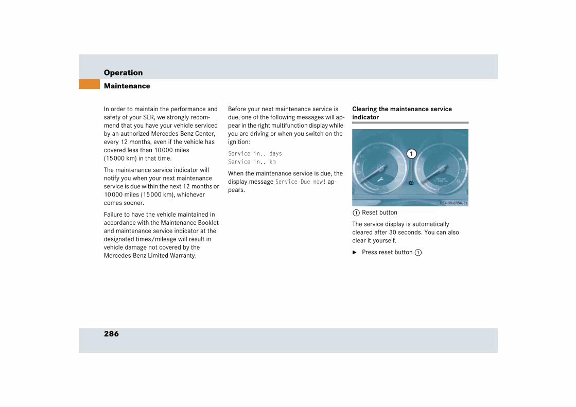
286
Operation
Maintenance
In order to maintain the performance and safety of your SLR, we strongly recom-mend that you have your vehicle serviced by an authorized Mercedes-Benz Center, every 12 months, even if the vehicle has covered less than 10000 miles (15000 km) in that time.
The maintenance service indicator will notify you when your next maintenance service is due within the next 12 months or 10000 miles (15000 km), whichever comes sooner.
Failure to have the vehicle maintained in accordance with the Maintenance Booklet and maintenance service indicator at the designated times/mileage will result in vehicle damage not covered by the Mercedes-Benz Limited Warranty.
Before your next maintenance service is due, one of the following messages will ap-pear in the right multifunction display while you are driving or when you switch on the ignition:
Service in.. daysService in.. km
When the maintenance service is due, the display message Service Due now! ap-pears.
Clearing the maintenance service indicator
1 Reset button
The service display is automatically cleared after 30 seconds. You can also clear it yourself.
� Press reset button 1.
287
Operation
Maintenance
Maintenance service term exceeded
If you have exceeded the suggested ser-vice term, you will see the following mes-sage in the right multifunction display:
Service exceeded by .. daysService exceeded by .. km
Any authorized Mercedes-Benz Center will reset the maintenance service indicator following a completed maintenance service.
Calling up the service due date
� Switch on the ignition (� page 40).
The standard display of the control system appears (� page 117).
� Press button k or j on the multifunction steering wheel until the maintenance service indicator service symbol 9 appears in the left multi-function display and the service dead-line appears in the right multifunction display.
iYou should not disconnect the consum-er battery if you do not intend to use your SLR for a longer period. Instead, maintain the condition of the battery by using the battery charger approved by Mercedes-Benz for use on the SLR and supplied with the car (� page 356). This charger automatically controls the charge rate, and can be left connected to the car for long periods without dam-age to the battery.
If the battery supplying the vehicle’s electrical consumers is disconnected, the days of disconnection will not be in-cluded in the count shown by the ser-vice indicator. To arrive at the true service deadline, you will need to sub-tract these days from the days shown in the service indicator.
Do not confuse the maintenance service indicator with the engine oil level indicator :.

288
Operation
Maintenance
Resetting the maintenance service indicator
In the event that the maintenance service on your vehicle is not carried out by an authorized Mercedes-Benz Center, you can have the maintenance service indicator reset. The automotive maintenance facility carrying out the maintenance service will find the information for resetting the maintenance service indicator in the maintenance-relevant information for your vehicle. Such information is available from either your authorized Mercedes-Benz Center or directly from Mercedes-Benz.
iIf the maintenance service indicator was inadvertently reset, have an authorized Mercedes-Benz Center correct it.
Only reset if the proper maintenance service has been performed. Resetting the system without performing the proper service as called for by the maintenance service indicator will result in engine damage and/or other vehicle damage not covered by the Mercedes-Benz Limited Warranty.
289
Operation
Vehicle care
� Vehicle careCleaning and care of the vehicle
If you have any questions about proper care of your SLR, please contact an autho-rized Mercedes-Benz Center.
Depending on body color the characteris-tic carbon structure of the body surface may become visible due to high ambient temperatures and humidity. This phenom-enon is related to the technology and con-cept of the vehicle’s body.
While in operation, even while parked, your vehicle is subjected to varying external influences which, if gone unchecked, can attack the paintwork as well as the under-body and cause lasting damage.
Such damage is caused not only by extreme and varying climatic conditions, but also by:
� Air pollution
� Road salt
� Tar
� Gravel and stone chipping
To avoid paint damage, you should immediately remove:
� Grease and oil
� Fuel
� Coolant
� Brake fluid
� Bird droppings
� Insects
� Tree resins, etc.
Frequent washing reduces and/or elimi-nates the aggressiveness and potency of the above adverse influences.
More frequent washings are necessary to deal with unfavorable conditions:
� near the ocean
� in industrial areas (smoke, exhaust emissions)
� during winter operation
You should check your vehicle from time to time for stone chipping or other damage. Any damage should be repaired as soon as possible to prevent corrosion.
Warning! G
Many cleaning products can be hazardous. Some are poisonous, others are flammable. Always follow the instructions on the partic-ular container. Always open your vehicle’s doors or windows when cleaning the inside.
Never use fluids or solvents that are not designed for cleaning your vehicle.
iMercedes-Benz recommends that you use Mercedes-Benz care products. These have been specially developed to suit Mercedes-Benz vehicles and are state of the art. Mercedes-Benz care products are available from any Mercedes-Benz Center.
290
Operation
Vehicle care
Vehicle washing To wash the car, use:
� a car shampoo, which is recommended by Mercedes-Benz
� a soft sponge or a washing brush
� plenty of water
� Spray the car down thoroughly using plenty of water.
� Wash out the sponge and chamois fre-quently.
� Rinse off with clean water.
� Dry the car well with a chamois.
Power washer
!When washing the vehicle, fine and rig-id particles in sponges or brushes could scratch or otherwise damage the paint. This applies to both, hand-wash or automatic car wash. Mercedes-Benz recommends you to have your vehicle cleaned at an automatic car wash from the start, preferably one without brush-es, or to use plenty of water when hand-washing your vehicle.
Do not wash the car in direct sunlight and when the body surface is hot.
In the winter, remove salt residue quickly and thoroughly.
!Do not use power washer to clean your vehicle or the engine.
291
Operation
Vehicle care
Wiper blades � Remove the SmartKey from the starter switch.
� Fold the wiper arm away from the wind-shield (� page 348).
You must feel the wiper arm engage in position. You can now clean the wiper blade.
� Clean the wiper blade insert with a clean cloth and detergent solution.
� After cleaning the wiper blade, fold the windshield wipers back again before turning the SmartKey in the starter switch.
!The hood must be opened (� page 243) before folding the wiper arm away from the windshield. You could otherwise damage the hood and/or the wiper arms.
!Never open or close the hood when the wiper arms are folded away from the windshield. You could otherwise dam-age the hood and/or the wiper arm.
Warning! G
For safety reasons, switch off wipers and remove SmartKey from starter switch before cleaning the wiper blades. Otherwise the wiper motor could suddenly turn on and cause injury.
!Fold the windshield wiper arms back onto the windshield before turning the SmartKey in the starter switch.
Hold on to the wiper when folding the wiper arm back. If released, the force of the impact from the tensioning spring could crack the windshield.
292
Operation
Vehicle care
Window cleaning � Remove the SmartKey from the starter switch.
� Fold the wiper arm away from the wind-shield (� page 348).
You must feel the wiper arm engage in position. You can now clean the wind-shield.
� Use a window cleaning solution on all glass surfaces.
An automotive glass cleaner is recom-mended.
� After cleaning the windshield, fold the windshield wipers back again before turning the SmartKey in the starter switch.
!The hood must be opened (� page 243) before folding the wiper arm away from the windshield. You could otherwise damage the hood and/or the wiper arms.
!Never open or close the hood when the wiper arms are folded away from the windshield. You could otherwise dam-age the hood and/or the wiper arm.
Warning! G
For safety reasons, switch off wipers and remove SmartKey from starter switch before cleaning the windshield. Otherwise the wiper motor could suddenly turn on and cause injury.
!Fold the windshield wiper arms back onto the windshield before turning the SmartKey in the starter switch.
Hold on to the wiper when folding the wiper arm back. If released, the force of the impact from the tensioning spring could crack the windshield.

293
Operation
Vehicle care
Cleaning the headlamps
� Wipe the headlamp lens with a damp sponge.
!Use only windshield washer fluid suit-able for plastic lamp lenses. Unsuitable windshield washer fluid may cause damage to the plastic lenses of the headlamps.
Do not use
� a dry cloth
� abrasive products
� solvents
� cleaning agents containing solvents
You could otherwise scratch or damage the lens surface.

Practical hints
What to do if ...
Where will I find ...?
Locking/unlocking in an emergency
Replacing SmartKey batteries
Replacing bulbs
Replacing the wiper blades
Flat tire
Batteries
Towing the vehicle
Fuses

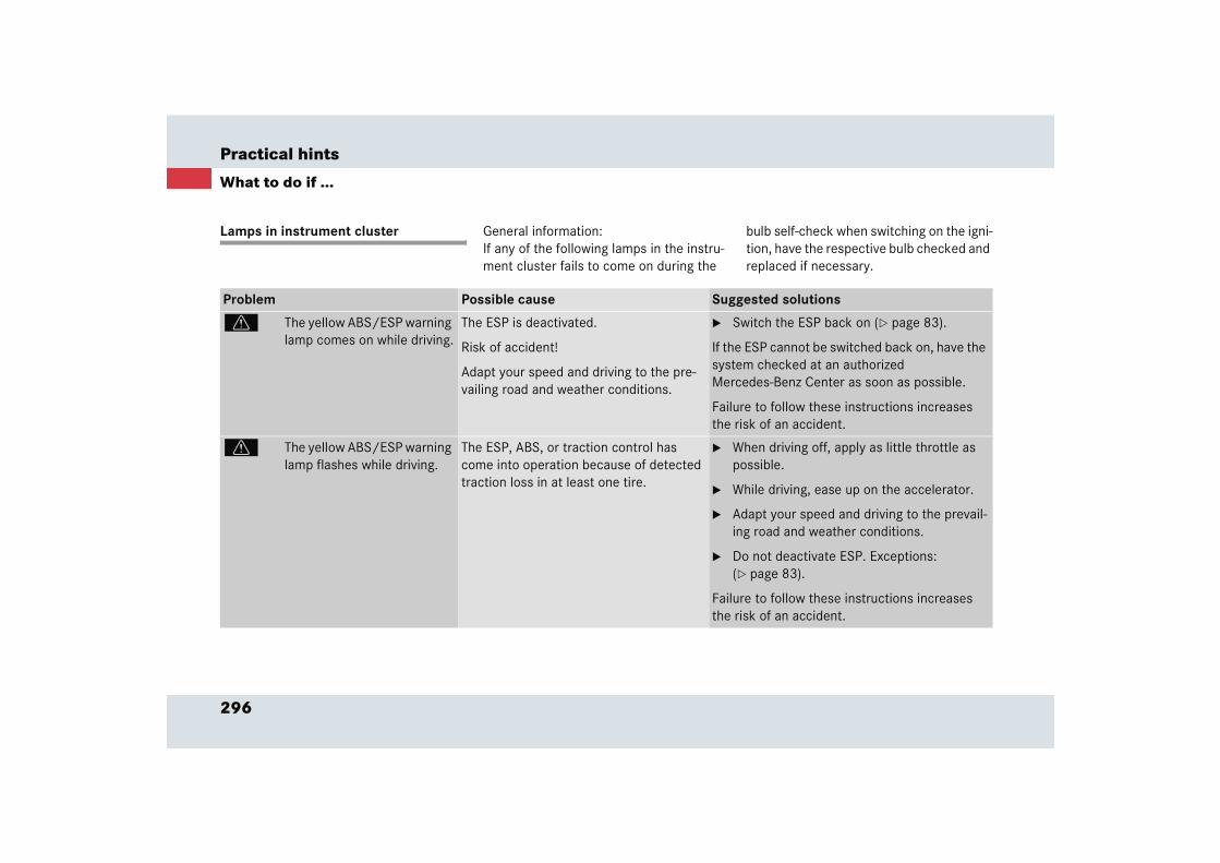
296
Practical hints
What to do if ...
Lamps in instrument cluster General information: If any of the following lamps in the instru-ment cluster fails to come on during the
bulb self-check when switching on the igni-tion, have the respective bulb checked and replaced if necessary.
Problem Possible cause Suggested solutions
v The yellow ABS/ESP warning lamp comes on while driving.
The ESP is deactivated.
Risk of accident!
Adapt your speed and driving to the pre-vailing road and weather conditions.
� Switch the ESP back on (� page 83).
If the ESP cannot be switched back on, have the system checked at an authorized Mercedes-Benz Center as soon as possible.
Failure to follow these instructions increases the risk of an accident.
v The yellow ABS/ESP warning lamp flashes while driving.
The ESP, ABS, or traction control has come into operation because of detected traction loss in at least one tire.
� When driving off, apply as little throttle as possible.
� While driving, ease up on the accelerator.
� Adapt your speed and driving to the prevail-ing road and weather conditions.
� Do not deactivate ESP. Exceptions: (� page 83).
Failure to follow these instructions increases the risk of an accident.
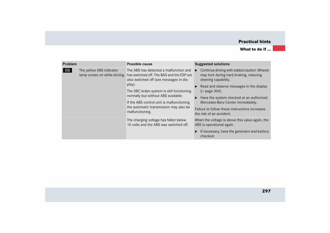
297
Practical hints
What to do if ...
Problem Possible cause Suggested solutions
- The yellow ABS indicator lamp comes on while driving.
The ABS has detected a malfunction and has switched off. The BAS and the ESP are also switched off (see messages in dis-play).
The SBC brake system is still functioning normally but without ABS available.
If the ABS control unit is malfunctioning the automatic transmission may also be malfunctioning.
� Continue driving with added caution. Wheels may lock during hard braking, reducing steering capability.
� Read and observe messages in the display (� page 304).
� Have the system checked at an authorized Mercedes-Benz Center immediately.
Failure to follow these instructions increases the risk of an accident.
The charging voltage has fallen below 10 volts and the ABS was switched off.
When the voltage is above this value again, the ABS is operational again.
� If necessary, have the generator and battery checked.
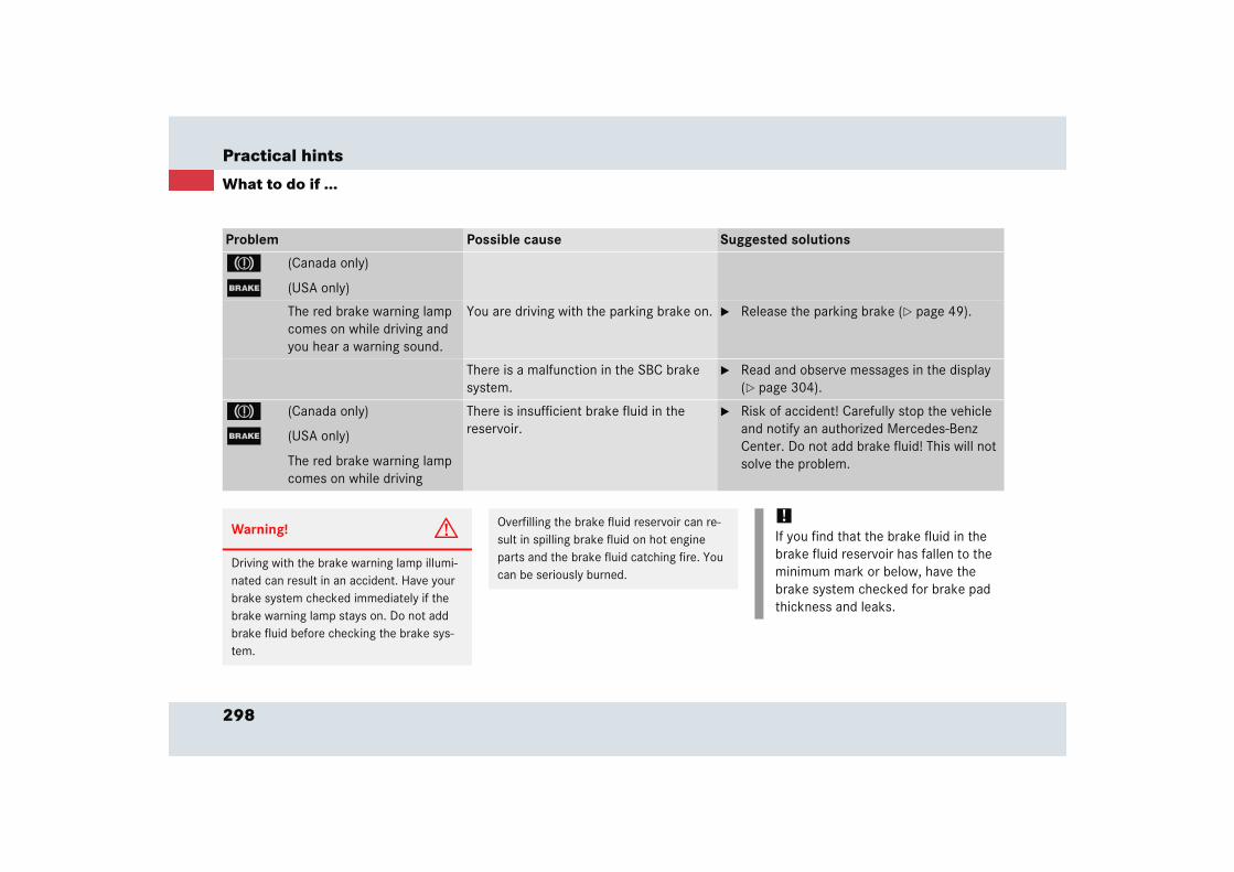
298
Practical hints
What to do if ...
Problem Possible cause Suggested solutions
3 (Canada only)
; (USA only)
The red brake warning lamp comes on while driving and you hear a warning sound.
You are driving with the parking brake on. � Release the parking brake (� page 49).
There is a malfunction in the SBC brake system.
� Read and observe messages in the display (� page 304).
3 (Canada only)
; (USA only)
The red brake warning lamp comes on while driving
There is insufficient brake fluid in the reservoir.
� Risk of accident! Carefully stop the vehicle and notify an authorized Mercedes-Benz Center. Do not add brake fluid! This will not solve the problem.
Warning! G
Driving with the brake warning lamp illumi-nated can result in an accident. Have your brake system checked immediately if the brake warning lamp stays on. Do not add brake fluid before checking the brake sys-tem.
Overfilling the brake fluid reservoir can re-sult in spilling brake fluid on hot engine parts and the brake fluid catching fire. You can be seriously burned.
!If you find that the brake fluid in the brake fluid reservoir has fallen to the minimum mark or below, have the brake system checked for brake pad thickness and leaks.
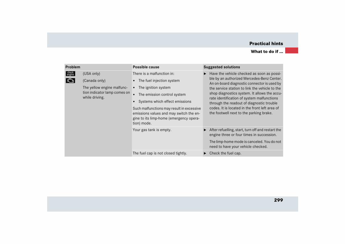
299
Practical hints
What to do if ...
Problem Possible cause Suggested solutions
ú (USA only)
± (Canada only)
The yellow engine malfunc-tion indicator lamp comes on while driving.
There is a malfunction in:
� The fuel injection system
� The ignition system
� The emission control system
� Systems which effect emissions
Such malfunctions may result in excessive emissions values and may switch the en-gine to its limp-home (emergency opera-tion) mode.
� Have the vehicle checked as soon as possi-ble by an authorized Mercedes-Benz Center.An on-board diagnostic connector is used by the service station to link the vehicle to the shop diagnostics system. It allows the accu-rate identification of system malfunctions through the readout of diagnostic trouble codes. It is located in the front left area of the footwell next to the parking brake.
Your gas tank is empty. � After refuelling, start, turn off and restart the engine three or four times in succession.
The limp-home mode is canceled. You do not need to have your vehicle checked.
The fuel cap is not closed tightly. � Check the fuel cap.
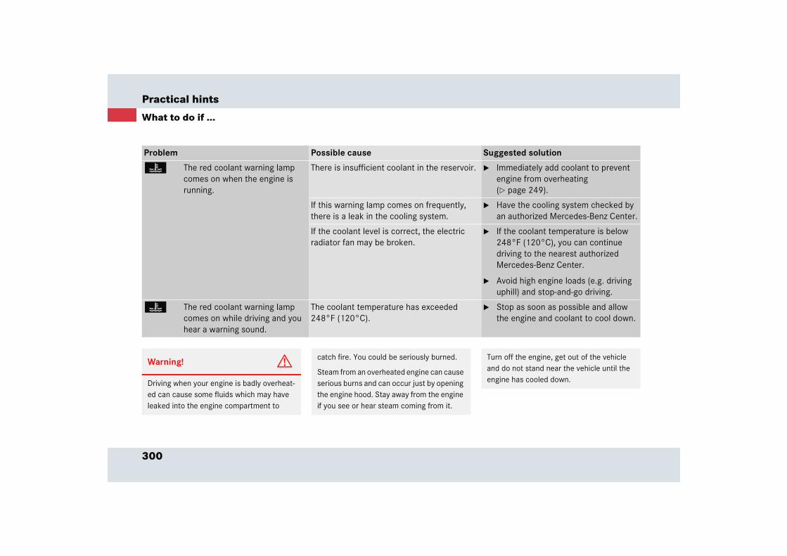
300
Practical hints
What to do if ...
Problem Possible cause Suggested solution
D The red coolant warning lamp comes on when the engine is running.
There is insufficient coolant in the reservoir. � Immediately add coolant to prevent engine from overheating (� page 249).
If this warning lamp comes on frequently, there is a leak in the cooling system.
� Have the cooling system checked by an authorized Mercedes-Benz Center.
If the coolant level is correct, the electric radiator fan may be broken.
� If the coolant temperature is below 248°F (120°C), you can continue driving to the nearest authorized Mercedes-Benz Center.
� Avoid high engine loads (e.g. driving uphill) and stop-and-go driving.
D The red coolant warning lamp comes on while driving and you hear a warning sound.
The coolant temperature has exceeded 248°F (120°C).
� Stop as soon as possible and allow the engine and coolant to cool down.
Warning! G
Driving when your engine is badly overheat-ed can cause some fluids which may have leaked into the engine compartment to
catch fire. You could be seriously burned.
Steam from an overheated engine can cause serious burns and can occur just by opening the engine hood. Stay away from the engine if you see or hear steam coming from it.
Turn off the engine, get out of the vehicle and do not stand near the vehicle until the engine has cooled down.
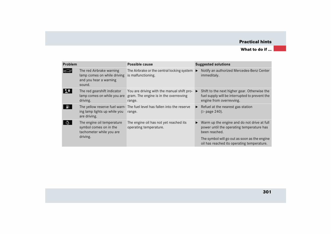
301
Practical hints
What to do if ...
Problem Possible cause Suggested solutions
< The red Airbrake warning lamp comes on while driving and you hear a warning sound.
The Airbrake or the central locking system is malfunctioning.
� Notify an authorized Mercedes-Benz Center immeditaly.
> The red gearshift indicator lamp comes on while you are driving.
You are driving with the manual shift pro-gram. The engine is in the overrevving range.
� Shift to the next higher gear. Otherwise the fuel supply will be interrupted to prevent the engine from overrevving.
A The yellow reserve fuel warn-ing lamp lights up while you are driving.
The fuel level has fallen into the reserve range.
� Refuel at the nearest gas station (� page 240).
= The engine oil temperature symbol comes on in the tachometer while you are driving.
The engine oil has not yet reached its operating temperature.
� Warm up the engine and do not drive at full power until the operating temperature has been reached.
The symbol will go out as soon as the engine oil has reached its operating temperature.
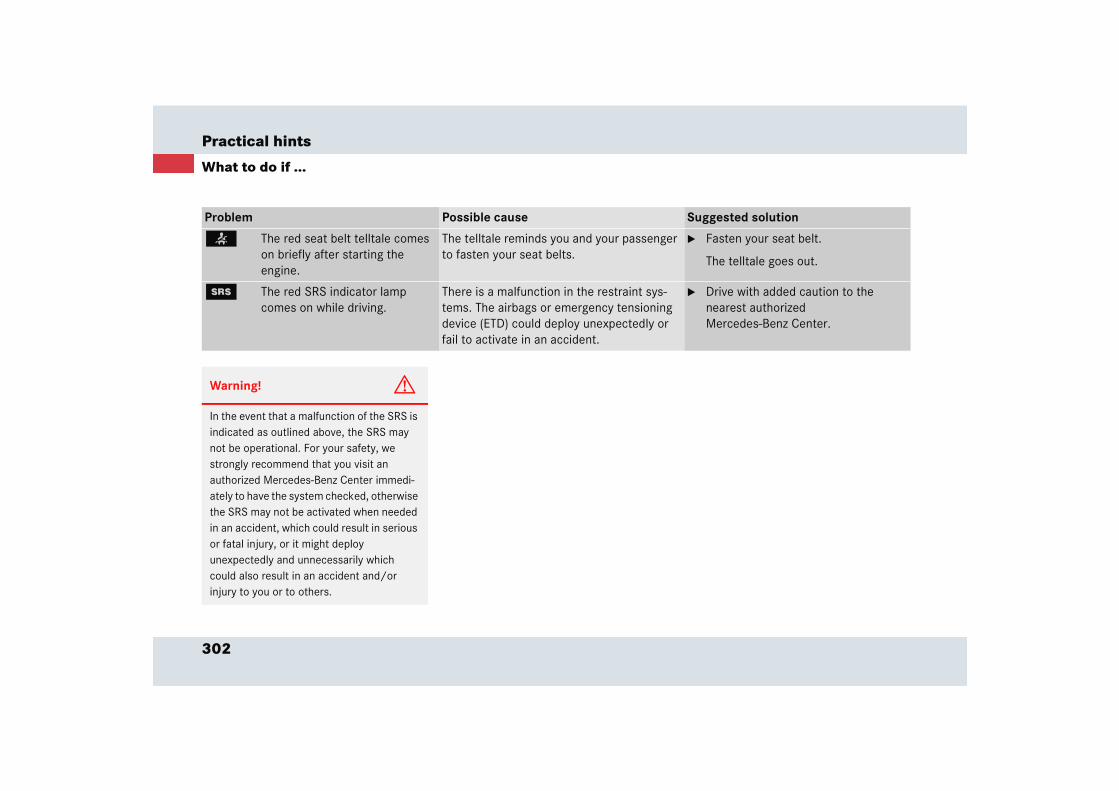
302
Practical hints
What to do if ...
Problem Possible cause Suggested solution
< The red seat belt telltale comes on briefly after starting the engine.
The telltale reminds you and your passenger to fasten your seat belts.
� Fasten your seat belt.
The telltale goes out.
1 The red SRS indicator lamp comes on while driving.
There is a malfunction in the restraint sys-tems. The airbags or emergency tensioning device (ETD) could deploy unexpectedly or fail to activate in an accident.
� Drive with added caution to the nearest authorized Mercedes-Benz Center.
Warning! G
In the event that a malfunction of the SRS is indicated as outlined above, the SRS may not be operational. For your safety, we strongly recommend that you visit an authorized Mercedes-Benz Center immedi-ately to have the system checked, otherwise the SRS may not be activated when needed in an accident, which could result in serious or fatal injury, or it might deploy unexpectedly and unnecessarily which could also result in an accident and/or injury to you or to others.
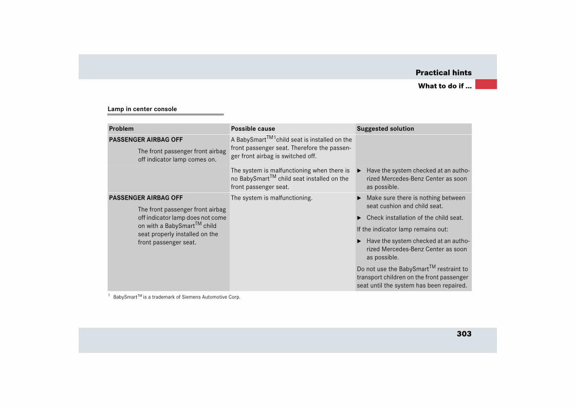
303
Practical hints
What to do if ...
Lamp in center console
Problem Possible cause Suggested solution
PASSENGER AIRBAG OFF
The front passenger front airbag off indicator lamp comes on.
A BabySmartTM1child seat is installed on the front passenger seat. Therefore the passen-ger front airbag is switched off.
1 BabySmartTM is a trademark of Siemens Automotive Corp.
The system is malfunctioning when there is no BabySmartTM child seat installed on the front passenger seat.
� Have the system checked at an autho-rized Mercedes-Benz Center as soon as possible.
PASSENGER AIRBAG OFF
The front passenger front airbag off indicator lamp does not come on with a BabySmartTM child seat properly installed on the front passenger seat.
The system is malfunctioning. � Make sure there is nothing between seat cushion and child seat.
� Check installation of the child seat.
If the indicator lamp remains out:
� Have the system checked at an autho-rized Mercedes-Benz Center as soon as possible.
Do not use the BabySmartTM restraint to transport children on the front passenger seat until the system has been repaired.
304
Practical hints
What to do if ...
Vehicle status messages in the multifunction display
Warning and malfunction messages appear in the multifunction display located in the instrument cluster.
Certain warning and malfunction messag-es are accompanied by an audible signal.
Address these messages accordingly and follow the additional instructions given in this Operator’s Manual.
Selecting the vehicle status message memory menu in the control system (� page 124) displays both cleared and uncleared messages.
High-priority messages appear in the multifunction display in red color.
Certain messages of high priority cannot be cleared from the multifunction display using the reset button (� page 29).
Other messages of high priority and messages of less immediate priority can be cleared from the multifunction display using the reset button. They are then stored in the vehicle status message mem-ory (� page 124). Remember that clearing a message will only make the message dis-appear. Clearing a message will not cor-rect the condition that caused the message to appear.
Warning! G
All categories of messages contain important information which should be taken note of and, where a malfunction is indicated, addressed as soon as possible at an authorized Mercedes-Benz Center.
Failure to repair condition noted may cause damage not covered by the Mercedes-Benz Limited Warranty, or result in property damage or personal injury.
Warning! G
No messages will be displayed if either the instrument cluster or the multifunction display is inoperative.
Contact your nearest authorized Mercedes-Benz Center.
iSwitching on the ignition causes all in-strument cluster lamps (except high beam headlamp indicator lamp and turn signal indicator lamps unless acti-vated) as well as the multifunction dis-play to come on. Make sure the lamps and multifunction display are in work-ing order before starting your journey.
305
Practical hints
What to do if ...
On the pages that follow, you will find a compilation of the most important warning and malfunction messages that may appear in the multifunction display. High priority messages appear in red color.
For your convenience the messages are di-vided into two sections:
� Text messages (� page 306)
� Symbol messages (� page 309)

306
Practical hints
What to do if ...
Text messages
Left display Right display Possible cause Possible solution
ABS malfunction!Visitworkshop!
The ABS has detected a mal-function and has switched off. The ESP and the BAS are also deactivated.
The SBC brake system is still functioning normally but with-out the ABS available.
� Continue driving with added caution.Wheels may lock during hard braking, reducing steering capability.
� Have the system checked at an authorized Mercedes-Benz Center immediately.
Failure to follow these instructions increases the risk of an accident.
Display malfunc-tionVisitworkshop!
The ABS or the ABS display is malfunctioning.
� Continue driving with added caution.Wheels may lock during hard braking, reducing steering capability.
� Have the system checked at an authorized Mercedes-Benz Center immediately.
Failure to follow these instructions increases the risk of an accident.

307
Practical hints
What to do if ...
Left display Right display Possible cause Possible solution
ESP malfunction!Visitworkshop!
The ESP has detected a mal-function and switched off. The SBC brake system is still func-tioning normally. The ABS may still be operational.
� Continue driving with added caution.
� Have the system checked at an authorized Mercedes-Benz Center immediately.
Failure to follow these instructions increases the risk of an accident.
Unavailable! See Oper.'s Man.
The ESP is deactivated because the power supply has been in-terrupted. The SBC brake sys-tem is still functioning normally.
� Synchronize the ESP. With the vehicle stationary, turn the steering wheel completely to the left and then to the right.
Ensure that you can turn the steering wheel to the stop without the wheels touching an object (e.g. the road curb).
If the ESP message does not go out:
� Continue driving with added caution.
� Have the system checked at an authorized Mercedes-Benz Center immediately.
Failure to follow these instructions increases the risk of an accident.
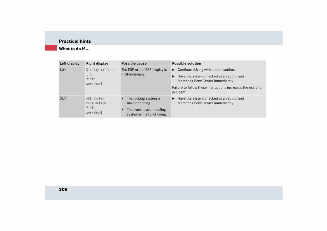
308
Practical hints
What to do if ...
Left display Right display Possible cause Possible solution
ESP Display malfunc-tionVisitworkshop!
The ESP or the ESP display is malfunctioning.
� Continue driving with added caution.
� Have the system checked at an authorized Mercedes-Benz Center immediately.
Failure to follow these instructions increases the risk of an accident.
SLR ACL systemmalfunctionVisitworkshop!
� The locking system is malfunctioning.
� The transmission cooling system is malfunctioning.
� Have the system checked at an authorized Mercedes-Benz Center immediately.
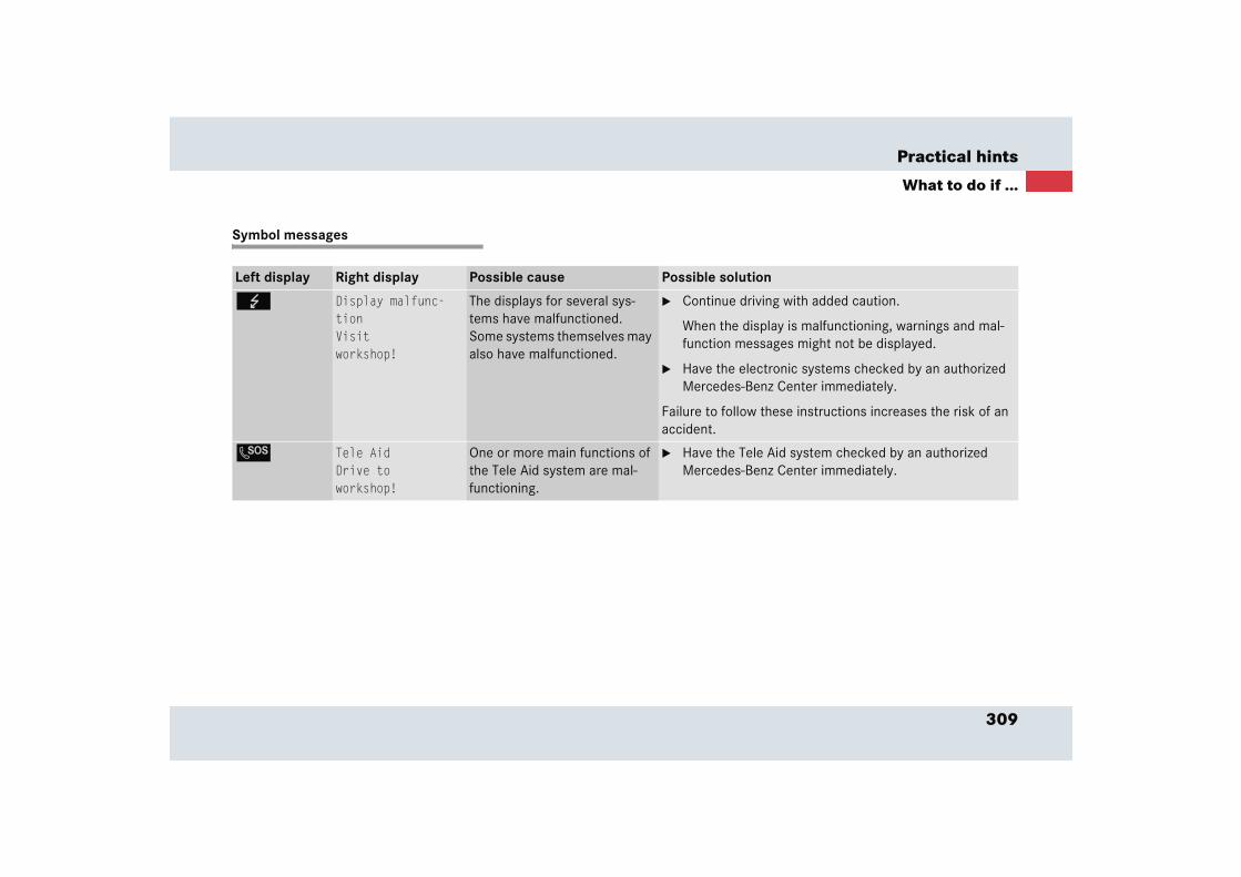
309
Practical hints
What to do if ...
Symbol messages
Left display Right display Possible cause Possible solution
G Display malfunc-tionVisitworkshop!
The displays for several sys-tems have malfunctioned. Some systems themselves may also have malfunctioned.
� Continue driving with added caution.
When the display is malfunctioning, warnings and mal-function messages might not be displayed.
� Have the electronic systems checked by an authorized Mercedes-Benz Center immediately.
Failure to follow these instructions increases the risk of an accident.
L Tele AidDrive toworkshop!
One or more main functions of the Tele Aid system are mal-functioning.
� Have the Tele Aid system checked by an authorized Mercedes-Benz Center immediately.

310
Practical hints
What to do if ...
Left display Right display Possible cause Possible solution
# Electricconsumersoffline!
The consumer battery has in-sufficient voltage and can no longer supply the convenience functions.
The electrical consumers will come back online as soon as on-board voltage is sufficient.
Battery/ Alternator Stop vehicle!
The battery or the alternator is malfunctioning.
The SBC brake system requires electrical energy and therefore has only limited operation. Considerably greater brake pedal force is required and the stopping distance is increased.
� Stop the vehicle as soon as it is safe to do so. Adjust driv-ing to be consistent with reduced braking responsive-ness.
� Notify an authorized Mercedes-Benz Center immediate-ly.
� Observe the additional messages in the instrument clus-ter.
Failure to follow these instructions increases the risk of an accident.
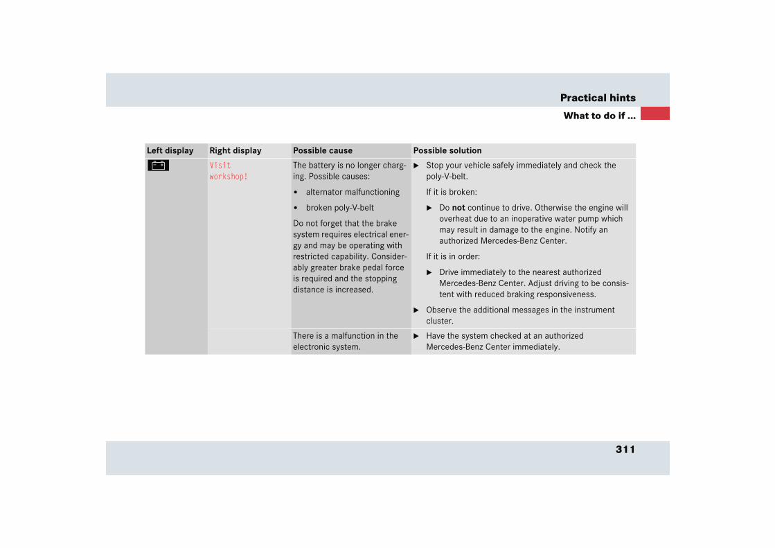
311
Practical hints
What to do if ...
Left display Right display Possible cause Possible solution
# Visitworkshop!
The battery is no longer charg-ing. Possible causes:
� alternator malfunctioning
� broken poly-V-belt
Do not forget that the brake system requires electrical ener-gy and may be operating with restricted capability. Consider-ably greater brake pedal force is required and the stopping distance is increased.
� Stop your vehicle safely immediately and check the poly-V-belt.
If it is broken:
� Do not continue to drive. Otherwise the engine will overheat due to an inoperative water pump which may result in damage to the engine. Notify an authorized Mercedes-Benz Center.
If it is in order:
� Drive immediately to the nearest authorized Mercedes-Benz Center. Adjust driving to be consis-tent with reduced braking responsiveness.
� Observe the additional messages in the instrument cluster.
There is a malfunction in the electronic system.
� Have the system checked at an authorized Mercedes-Benz Center immediately.
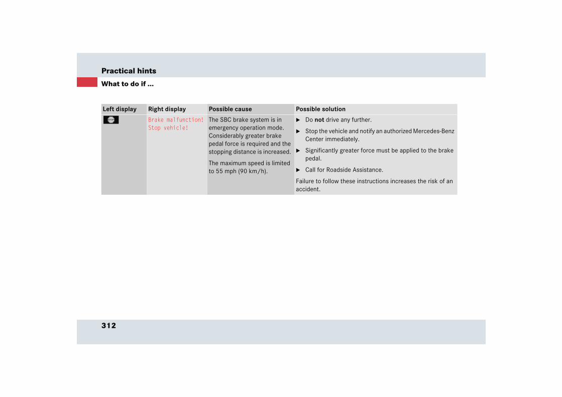
312
Practical hints
What to do if ...
Left display Right display Possible cause Possible solution
T Brake malfunction!Stop vehicle!
The SBC brake system is in emergency operation mode. Considerably greater brake pedal force is required and the stopping distance is increased.
The maximum speed is limited to 55 mph (90 km/h).
� Do not drive any further.
� Stop the vehicle and notify an authorized Mercedes-Benz Center immediately.
� Significantly greater force must be applied to the brake pedal.
� Call for Roadside Assistance.
Failure to follow these instructions increases the risk of an accident.

313
Practical hints
What to do if ...
Left display Right display Possible cause Possible solution
; (USA only)
3 (Canada only)
Reducedbrake effectVisitworkshop!
The SBC brake system is in emergency operation mode. Considerable brake pedal force is re-quired and the stopping distance is increased.
� Continue driving with added caution.
� Visit an authorized Mercedes-Benz Center immedi-ately. Adjust driving to be consistent with reduced braking responsiveness.
Failure to follow these instructions increases the risk of an accident.
Increasedbraking distanceVisitworkshop!
Warning! G
Driving while these messages are displayed can result in an accident. Have your brake system checked immediately.
If there is a malfunction in the SBC brake system, we recommend that the vehicle be transported with all wheels off the ground using flatbed or appropriate wheel lift/dolly equipment.
A tow bar must be used if circumstances do not permit the use of the recommended towing methods and the vehicle requires towing with all four wheels on the ground.
Towing the vehicle with all four wheels on the ground is only permissible for distances up to 30 miles (50 km) and at a speed not to exceed 30 mph (50 km/h). For more infor-mation, see “Towing the vehicle” (� page 357).
If the SBC brake system enters its emergen-cy operation mode, the driver must apply significantly greater brake pedal pressure and depress the pedal much further than normal to obtain braking effect.
If necessary, apply full pressure to the brake pedal. Stopping distance is increased!
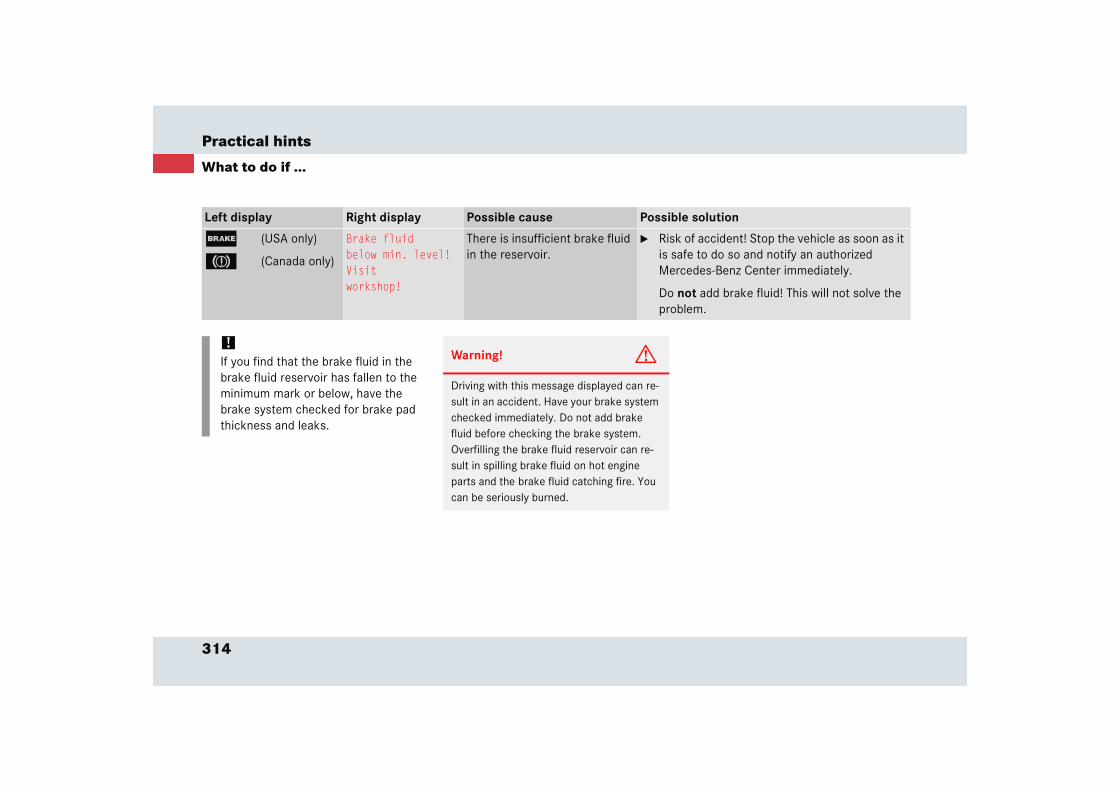
314
Practical hints
What to do if ...
Left display Right display Possible cause Possible solution
; (USA only)
3 (Canada only)
Brake fluidbelow min. level!Visitworkshop!
There is insufficient brake fluid in the reservoir.
� Risk of accident! Stop the vehicle as soon as it is safe to do so and notify an authorized Mercedes-Benz Center immediately.
Do not add brake fluid! This will not solve the problem.
!If you find that the brake fluid in the brake fluid reservoir has fallen to the minimum mark or below, have the brake system checked for brake pad thickness and leaks.
Warning! G
Driving with this message displayed can re-sult in an accident. Have your brake system checked immediately. Do not add brake fluid before checking the brake system. Overfilling the brake fluid reservoir can re-sult in spilling brake fluid on hot engine parts and the brake fluid catching fire. You can be seriously burned.

315
Practical hints
What to do if ...
Left display Right display Possible cause Possible solution
; (USA only)
3 (Canada only)
Reducedbrake effectStart engine!
The battery has insufficient voltage and cannot supply suffi-cient power to the SBC brake system.
� Start the engine.
As soon as the engine is running, the message disappears.
Increasedbraking distanceStart engine!
Warning! G
Inhalation of exhaust gas is hazardous to your health. All exhaust gas contains carbon monoxide, and inhaling it can cause uncon-sciousness and lead to death.
Do not run the engine in confined areas (such as a garage) which are not properly ventilated.

316
Practical hints
What to do if ...
Left display Right display Possible cause Possible solution
; (USA only)
3 (Canada only)
Brakes overheated!Drive carefully
The brake system is overheated due to an excessive load on the brakes.
� Relieve the load on the brake system.
� Drive more smoothly and think ahead to avoid unnecessary braking.
� When driving down steep grades, shift into a lower gear to use the engine’s braking power (� page 170).
� Cautiously continue driving so that the air stream will cool down the brakes.
Releaseparking brake!
You are driving with the parking brake set.
� Release the parking brake (� page 49).
Service brakeVisitworkshop!
There are malfunctions, but the SBC brake system is operating normally.
� Visit an authorized Mercedes-Benz Center im-mediately.
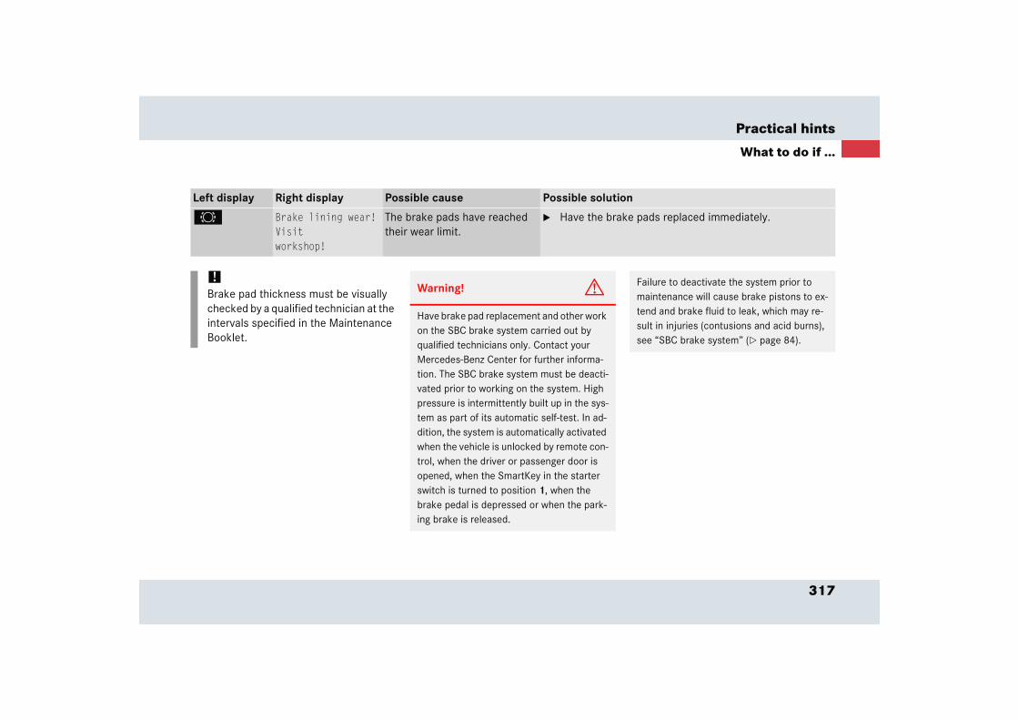
317
Practical hints
What to do if ...
Left display Right display Possible cause Possible solution
2 Brake lining wear!Visitworkshop!
The brake pads have reached their wear limit.
� Have the brake pads replaced immediately.
!Brake pad thickness must be visually checked by a qualified technician at the intervals specified in the Maintenance Booklet.
Warning! G
Have brake pad replacement and other work on the SBC brake system carried out by qualified technicians only. Contact your Mercedes-Benz Center for further informa-tion. The SBC brake system must be deacti-vated prior to working on the system. High pressure is intermittently built up in the sys-tem as part of its automatic self-test. In ad-dition, the system is automatically activated when the vehicle is unlocked by remote con-trol, when the driver or passenger door is opened, when the SmartKey in the starter switch is turned to position 1, when the brake pedal is depressed or when the park-ing brake is released.
Failure to deactivate the system prior to maintenance will cause brake pistons to ex-tend and brake fluid to leak, which may re-sult in injuries (contusions and acid burns), see “SBC brake system” (� page 84).
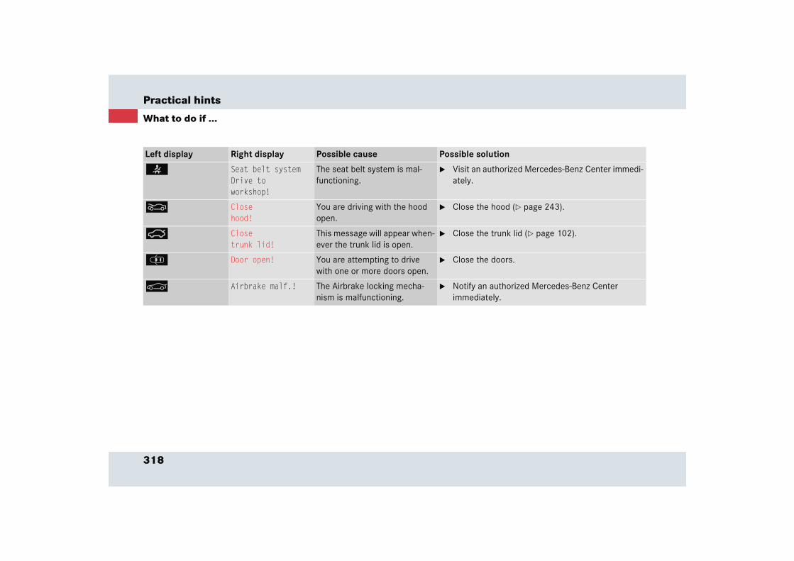
318
Practical hints
What to do if ...
Left display Right display Possible cause Possible solution
< Seat belt systemDrive toworkshop!
The seat belt system is mal-functioning.
� Visit an authorized Mercedes-Benz Center immedi-ately.
O Closehood!
You are driving with the hood open.
� Close the hood (� page 243).
Ê Closetrunk lid!
This message will appear when-ever the trunk lid is open.
� Close the trunk lid (� page 102).
J Door open! You are attempting to drive with one or more doors open.
� Close the doors.
< Airbrake malf.! The Airbrake locking mecha-nism is malfunctioning.
� Notify an authorized Mercedes-Benz Center immediately.
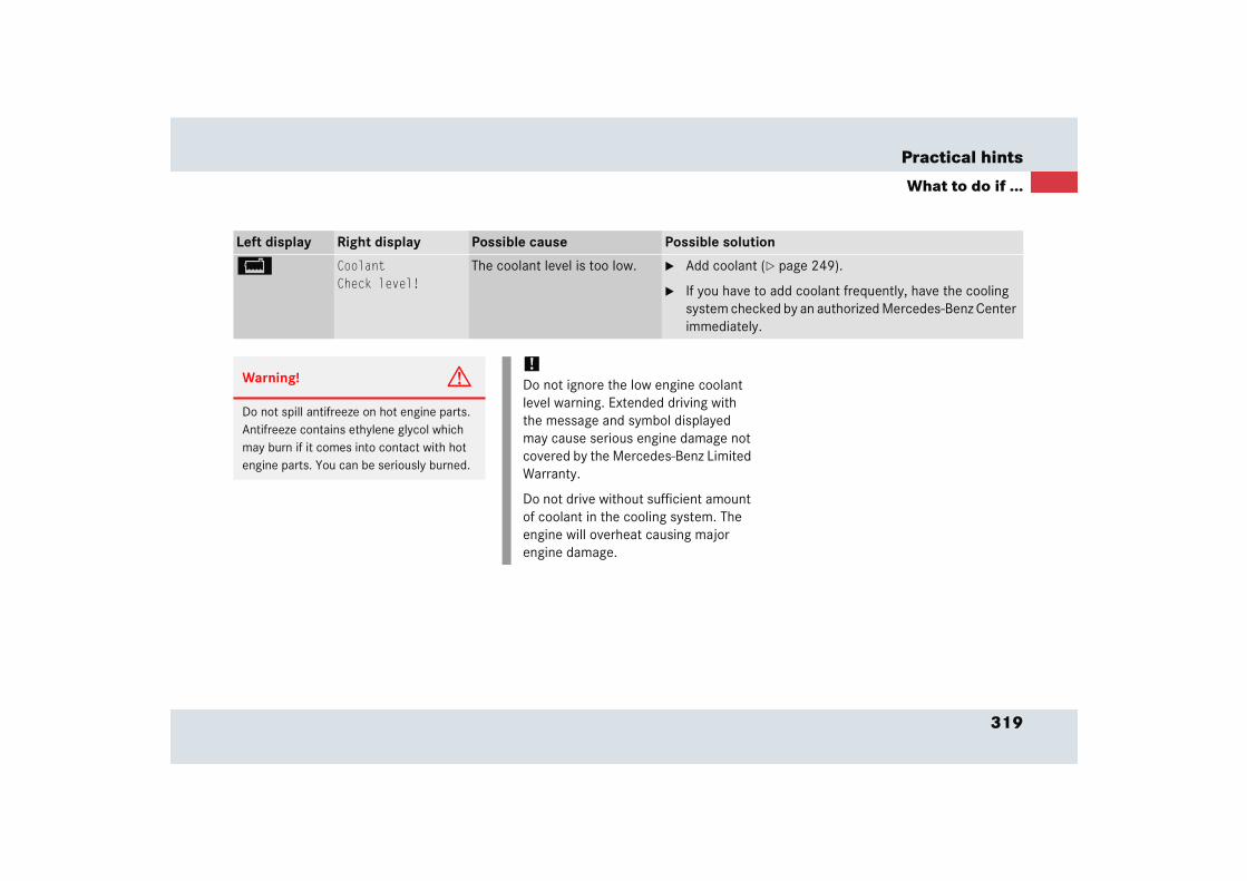
319
Practical hints
What to do if ...
Left display Right display Possible cause Possible solution
B CoolantCheck level!
The coolant level is too low. � Add coolant (� page 249).
� If you have to add coolant frequently, have the cooling system checked by an authorized Mercedes-Benz Center immediately.
Warning! G
Do not spill antifreeze on hot engine parts. Antifreeze contains ethylene glycol which may burn if it comes into contact with hot engine parts. You can be seriously burned.
!Do not ignore the low engine coolant level warning. Extended driving with the message and symbol displayed may cause serious engine damage not covered by the Mercedes-Benz Limited Warranty.
Do not drive without sufficient amount of coolant in the cooling system. The engine will overheat causing major engine damage.
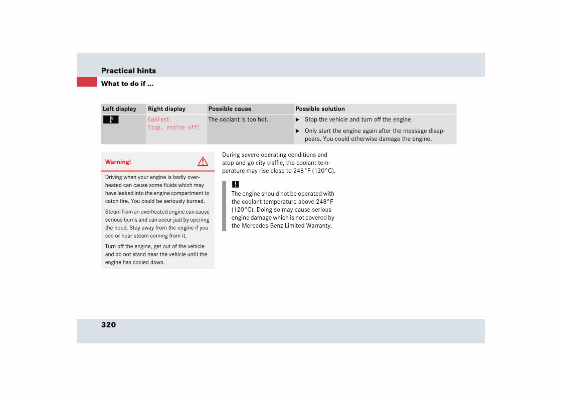
320
Practical hints
What to do if ...
During severe operating conditions and stop-and-go city traffic, the coolant tem-perature may rise close to 248°F (120°C).
Left display Right display Possible cause Possible solution
Ï CoolantStop, engine off!
The coolant is too hot. � Stop the vehicle and turn off the engine.
� Only start the engine again after the message disap-pears. You could otherwise damage the engine.
Warning! G
Driving when your engine is badly over-heated can cause some fluids which may have leaked into the engine compartment to catch fire. You could be seriously burned.
Steam from an overheated engine can cause serious burns and can occur just by opening the hood. Stay away from the engine if you see or hear steam coming from it.
Turn off the engine, get out of the vehicle and do not stand near the vehicle until the engine has cooled down.
!The engine should not be operated with the coolant temperature above 248°F (120°C). Doing so may cause serious engine damage which is not covered by the Mercedes-Benz Limited Warranty.
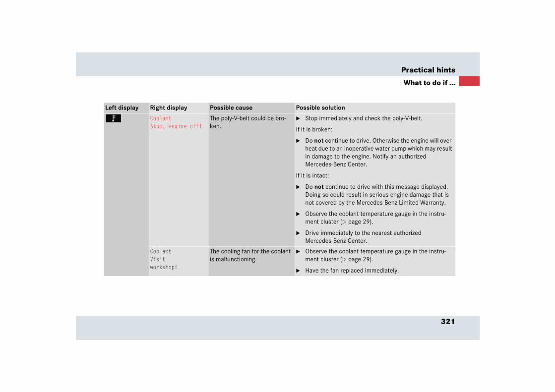
321
Practical hints
What to do if ...
Left display Right display Possible cause Possible solution
Ï CoolantStop, engine off!
The poly-V-belt could be bro-ken.
� Stop immediately and check the poly-V-belt.
If it is broken:
� Do not continue to drive. Otherwise the engine will over-heat due to an inoperative water pump which may result in damage to the engine. Notify an authorized Mercedes-Benz Center.
If it is intact:
� Do not continue to drive with this message displayed. Doing so could result in serious engine damage that is not covered by the Mercedes-Benz Limited Warranty.
� Observe the coolant temperature gauge in the instru-ment cluster (� page 29).
� Drive immediately to the nearest authorized Mercedes-Benz Center.
CoolantVisitworkshop!
The cooling fan for the coolant is malfunctioning.
� Observe the coolant temperature gauge in the instru-ment cluster (� page 29).
� Have the fan replaced immediately.
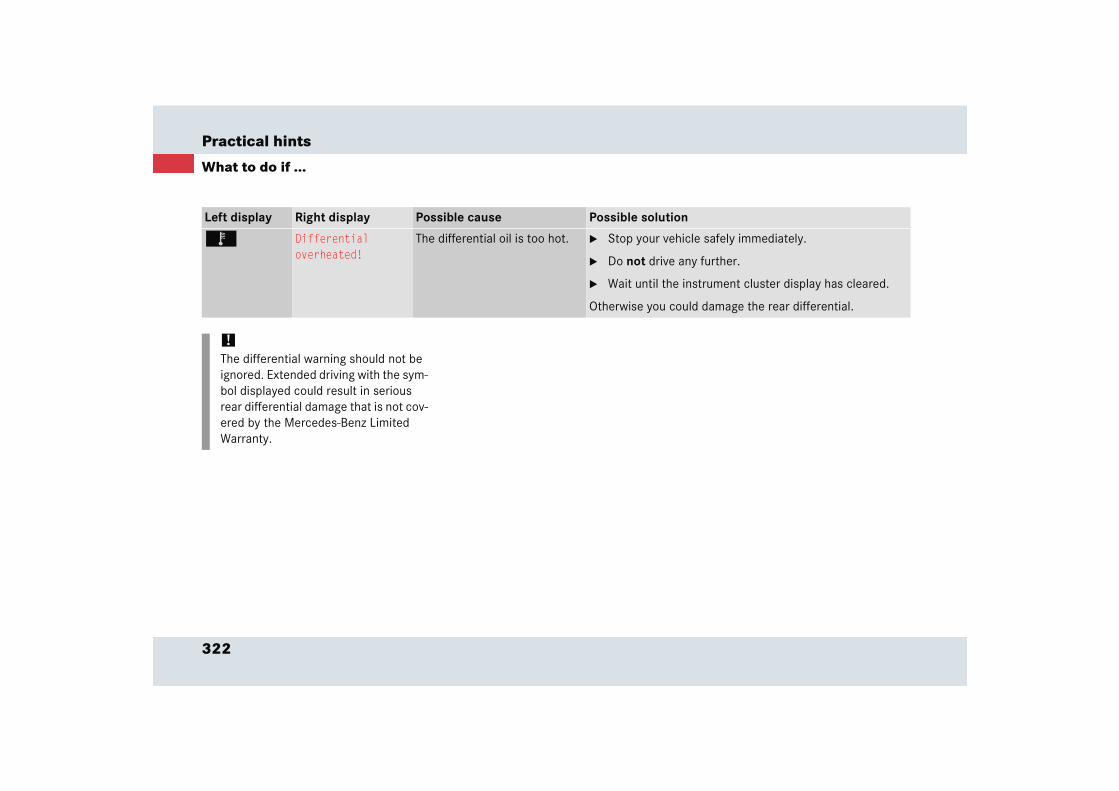
322
Practical hints
What to do if ...
Left display Right display Possible cause Possible solution
Ï Differentialoverheated!
The differential oil is too hot. � Stop your vehicle safely immediately.
� Do not drive any further.
� Wait until the instrument cluster display has cleared.
Otherwise you could damage the rear differential.
!The differential warning should not be ignored. Extended driving with the sym-bol displayed could result in serious rear differential damage that is not cov-ered by the Mercedes-Benz Limited Warranty.

323
Practical hints
What to do if ...
Left display Right display Possible cause Possible solution
. Low beamLeft
The left low beam lamp is mal-functioning.
� Visit an authorized Mercedes-Benz Center as soon as possible.
Low beamRight
The right low beam lamp is mal-functioning.
� Visit an authorized Mercedes-Benz Center as soon as possible.
High beamLeft
The left high beam lamp is mal-functioning.
� Visit an authorized Mercedes-Benz Center as soon as possible.
High beamRight
The right high beam lamp is malfunctioning.
� Visit an authorized Mercedes-Benz Center as soon as possible.
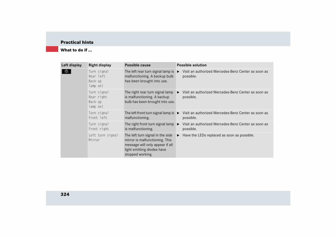
324
Practical hints
What to do if ...
Left display Right display Possible cause Possible solution
. Turn signalRear leftBack-uplamp on!
The left rear turn signal lamp is malfunctioning. A backup bulb has been brought into use.
� Visit an authorized Mercedes-Benz Center as soon as possible.
Turn signalRear rightBack-uplamp on!
The right rear turn signal lamp is malfunctioning. A backup bulb has been brought into use.
� Visit an authorized Mercedes-Benz Center as soon as possible.
Turn signalFront left
The left front turn signal lamp is malfunctioning.
� Visit an authorized Mercedes-Benz Center as soon as possible.
Turn signalFront right
The right front turn signal lamp is malfunctioning.
� Visit an authorized Mercedes-Benz Center as soon as possible.
Left turn signalMirror
The left turn signal in the side mirror is malfunctioning. This message will only appear if all light emitting diodes have stopped working.
� Have the LEDs replaced as soon as possible.

325
Practical hints
What to do if ...
Left display Right display Possible cause Possible solution
. Marker lampFront left
The front left side marker lamp is malfunctioning.
� Replace the bulb as soon as possible.
Marker lampFront right
The front right side marker lamp is malfunctioning.
� Replace the bulb as soon as possible.
Marker lampRear left
The rear left side marker lamp is malfunctioning.
� Replace the bulb as soon as possible.
Marker lampRear right
The rear right side marker lamp is malfunctioning.
� Replace the bulb as soon as possible.
Right turn signalMirror
The right turn signal in the side mirror is malfunctioning. This message will only appear if all light emitting diodes have stopped working.
� Have the LEDs replaced as soon as possible.
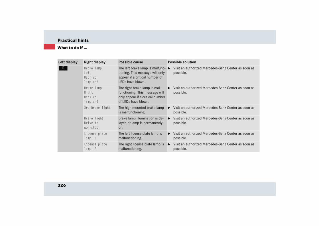
326
Practical hints
What to do if ...
Left display Right display Possible cause Possible solution
. Brake lampLeftBack-uplamp on!
The left brake lamp is malfunc-tioning. This message will only appear if a critical number of LEDs have blown.
� Visit an authorized Mercedes-Benz Center as soon as possible.
Brake lampRightBack-uplamp on!
The right brake lamp is mal-functioning. This message will only appear if a critical number of LEDs have blown.
� Visit an authorized Mercedes-Benz Center as soon as possible.
3rd brake light The high mounted brake lamp is malfunctioning.
� Visit an authorized Mercedes-Benz Center as soon as possible.
Brake lightDrive toworkshop!
Brake lamp illumination is de-layed or lamp is permanently on.
� Visit an authorized Mercedes-Benz Center as soon as possible.
License platelamp, L
The left license plate lamp is malfunctioning.
� Visit an authorized Mercedes-Benz Center as soon as possible.
License platelamp, R
The right license plate lamp is malfunctioning.
� Visit an authorized Mercedes-Benz Center as soon as possible.
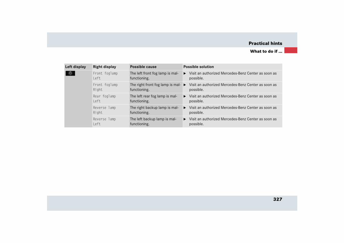
327
Practical hints
What to do if ...
Left display Right display Possible cause Possible solution
. Front foglampLeft
The left front fog lamp is mal-functioning.
� Visit an authorized Mercedes-Benz Center as soon as possible.
Front foglampRight
The right front fog lamp is mal-functioning.
� Visit an authorized Mercedes-Benz Center as soon as possible.
Rear foglampLeft
The left rear fog lamp is mal-functioning.
� Visit an authorized Mercedes-Benz Center as soon as possible.
Reverse lampRight
The right backup lamp is mal-functioning.
� Visit an authorized Mercedes-Benz Center as soon as possible.
Reverse lampLeft
The left backup lamp is mal-functioning.
� Visit an authorized Mercedes-Benz Center as soon as possible.
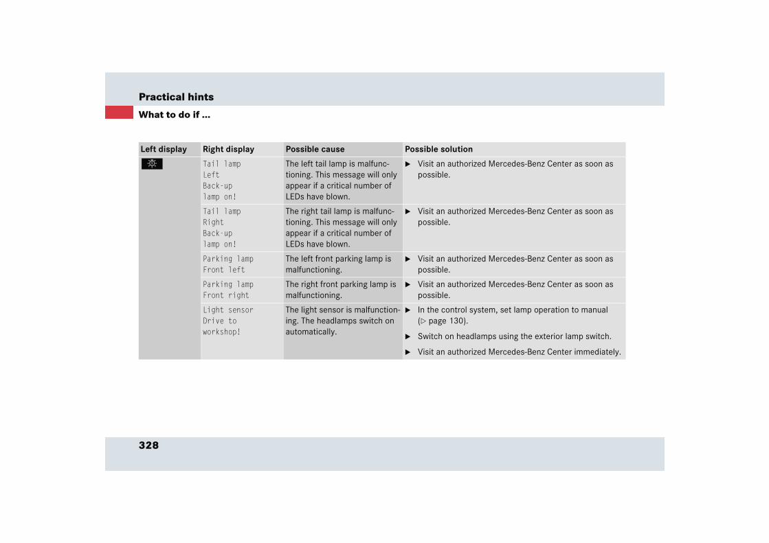
328
Practical hints
What to do if ...
Left display Right display Possible cause Possible solution
. Tail lampLeftBack-uplamp on!
The left tail lamp is malfunc-tioning. This message will only appear if a critical number of LEDs have blown.
� Visit an authorized Mercedes-Benz Center as soon as possible.
Tail lampRightBack-uplamp on!
The right tail lamp is malfunc-tioning. This message will only appear if a critical number of LEDs have blown.
� Visit an authorized Mercedes-Benz Center as soon as possible.
Parking lampFront left
The left front parking lamp is malfunctioning.
� Visit an authorized Mercedes-Benz Center as soon as possible.
Parking lampFront right
The right front parking lamp is malfunctioning.
� Visit an authorized Mercedes-Benz Center as soon as possible.
Light sensorDrive toworkshop!
The light sensor is malfunction-ing. The headlamps switch on automatically.
� In the control system, set lamp operation to manual (� page 130).
� Switch on headlamps using the exterior lamp switch.
� Visit an authorized Mercedes-Benz Center immediately.

329
Practical hints
What to do if ...
Left display Right display Possible cause Possible solution
± Display malfunc-tionVisitworkshop!
Certain electronic systems are unable to relay information to the control system. The follow-ing systems may have failed:
� Coolant temperature gauge
� Tachometer
� Cruise control display
� Have the electronic systems checked by an authorized Mercedes-Benz Center immediately.
Fuel systemmalfunctionVisitworkshop!
The fuel cooling system is malfunctioning.
� Visit an authorized Mercedes-Benz Center immediately.
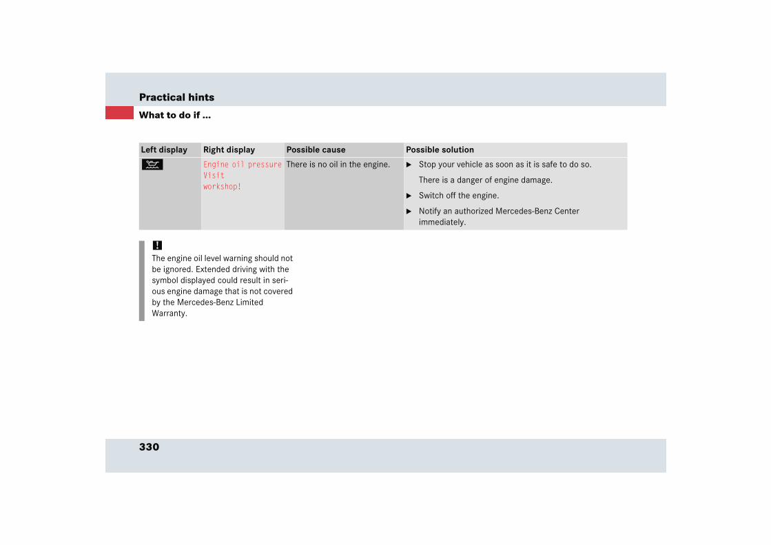
330
Practical hints
What to do if ...
Left display Right display Possible cause Possible solution
: Engine oil pressureVisitworkshop!
There is no oil in the engine. � Stop your vehicle as soon as it is safe to do so.
There is a danger of engine damage.
� Switch off the engine.
� Notify an authorized Mercedes-Benz Center immediately.
!The engine oil level warning should not be ignored. Extended driving with the symbol displayed could result in seri-ous engine damage that is not covered by the Mercedes-Benz Limited Warranty.

331
Practical hints
What to do if ...
Left display Right display Possible cause Possible solution
H Tire pressureCautiontire defect!
The tire inflation pressure in one or more tires is dropping.
� Carefully bring the vehicle to a halt, avoiding abrupt steering and braking maneuvers. Observe the traffic situation around you.
� Temporarily repair tire using TIREFIT (� page 349) or contact Roadside Assistance. If tire cannot be tempo-rarily repaired using TIREFIT, contact Roadside Assis-tance.
� Have the damaged wheel repaired or replaced at an authorized Mercedes-Benz Center.
Warning! G
Do not drive with a flat tire. A flat tire affects the ability to steer or brake the vehicle. You may lose control of the vehicle.
Continued driving with a flat tire will cause excessive heat build-up and possibly a fire.
Warning! G
Have worn or damaged tires replaced in pairs (front pair or rear pair). Otherwise the driving stability of the vehicle will be ad-versely affected.
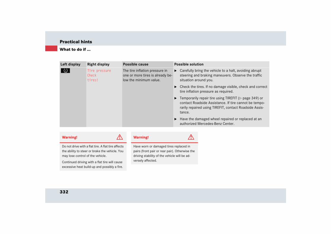
332
Practical hints
What to do if ...
Left display Right display Possible cause Possible solution
H Tire pressureChecktires!
The tire inflation pressure in one or more tires is already be-low the minimum value.
� Carefully bring the vehicle to a halt, avoiding abrupt steering and braking maneuvers. Observe the traffic situation around you.
� Check the tires. If no damage visible, check and correct tire inflation pressure as required.
� Temporarily repair tire using TIREFIT (� page 349) or contact Roadside Assistance. If tire cannot be tempo-rarily repaired using TIREFIT, contact Roadside Assis-tance.
� Have the damaged wheel repaired or replaced at an authorized Mercedes-Benz Center.
Warning! G
Do not drive with a flat tire. A flat tire affects the ability to steer or brake the vehicle. You may lose control of the vehicle.
Continued driving with a flat tire will cause excessive heat build-up and possibly a fire.
Warning! G
Have worn or damaged tires replaced in pairs (front pair or rear pair). Otherwise the driving stability of the vehicle will be ad-versely affected.
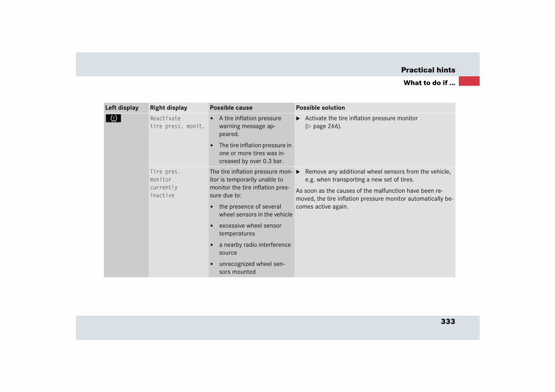
333
Practical hints
What to do if ...
Left display Right display Possible cause Possible solution
H Reactivatetire press. monit.
� A tire inflation pressure warning message ap-peared.
� The tire inflation pressure in one or more tires was in-creased by over 0.3 bar.
� Activate the tire inflation pressure monitor (� page 266).
Tire pres.monitorcurrentlyinactive
The tire inflation pressure mon-itor is temporarily unable to monitor the tire inflation pres-sure due to:
� the presence of several wheel sensors in the vehicle
� excessive wheel sensor temperatures
� a nearby radio interference source
� unrecognized wheel sen-sors mounted
� Remove any additional wheel sensors from the vehicle, e.g. when transporting a new set of tires.
As soon as the causes of the malfunction have been re-moved, the tire inflation pressure monitor automatically be-comes active again.

334
Practical hints
What to do if ...
Left display Right display Possible cause Possible solution
H Tire pres.monitorVisitworkshop!
The tire inflation pressure mon-itor is malfunctioning or one of the wheel sensors is malfunc-tioning.
� Have the tire inflation pressure monitor checked by an authorized Mercedes-Benz Center.
A wheel without proper sensor was installed.
� Have the wheels checked.

335
Practical hints
What to do if ...
Left display Right display Possible cause Possible solution
H Tire pressure, RLCautiontire defect!
The left rear tire is rapidly de-flating.
� Carefully bring the vehicle to a halt, avoiding abrupt steering and braking maneuvers. Observe the traffic situation around you.
� Temporarily repair tire using TIREFIT (� page 349) or contact Roadside Assistance. If tire cannot be tempo-rarily repaired using TIREFIT, contact Roadside Assis-tance.
� Have the damaged wheel repaired or replaced at an authorized Mercedes-Benz Center.
Tire pressure, RLChecktires!
The left rear tire inflation pres-sure is low.
� Carefully bring the vehicle to a halt.
� Check the tires. If no damage visible, check and correct tire inflation pressure as required.
� If necessary, have the wheel repaired or replaced at an authorized Mercedes-Benz Center.
Warning! G
Do not drive with a flat tire. A flat tire affects the ability to steer or brake the vehicle. You may lose control of the vehicle.
Continued driving with a flat tire will cause excessive heat build-up and possibly a fire.
Warning! G
Have worn or damaged tires replaced in pairs (front pair or rear pair). Otherwise the driving stability of the vehicle will be ad-versely affected.

336
Practical hints
What to do if ...
Left display Right display Possible cause Possible solution
H Tire pressure, RRCautiontire defect!
The right rear tire is rapidly de-flating.
� Carefully bring the vehicle to a halt, avoiding abrupt steering and braking maneuvers. Observe the traffic situation around you.
� Temporarily repair tire using TIREFIT (� page 349) or contact Roadside Assistance. If tire cannot be tempo-rarily repaired using TIREFIT, contact Roadside Assis-tance.
� Have the damaged wheel repaired or replaced at an authorized Mercedes-Benz Center.
Tire pressure, RRChecktires!
The right rear tire inflation pres-sure is low.
� Carefully bring the vehicle to a halt.
� Check the tires. If no damage visible, check and correct tire inflation pressure as required.
� If necessary, have the wheel repaired or replaced at an authorized Mercedes-Benz Center.
Warning! G
Do not drive with a flat tire. A flat tire affects the ability to steer or brake the vehicle. You may lose control of the vehicle.
Continued driving with a flat tire will cause excessive heat build-up and possibly a fire.
Warning! G
Have worn or damaged tires replaced in pairs (front pair or rear pair). Otherwise the driving stability of the vehicle will be ad-versely affected.
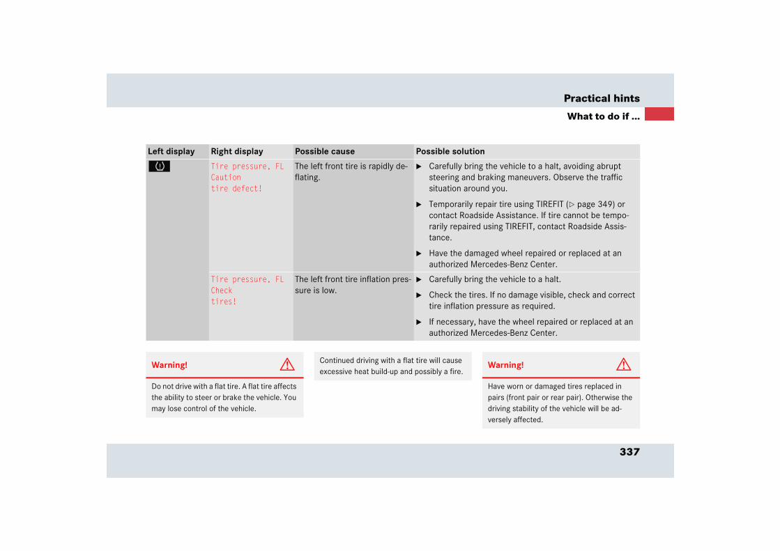
337
Practical hints
What to do if ...
Left display Right display Possible cause Possible solution
H Tire pressure, FLCautiontire defect!
The left front tire is rapidly de-flating.
� Carefully bring the vehicle to a halt, avoiding abrupt steering and braking maneuvers. Observe the traffic situation around you.
� Temporarily repair tire using TIREFIT (� page 349) or contact Roadside Assistance. If tire cannot be tempo-rarily repaired using TIREFIT, contact Roadside Assis-tance.
� Have the damaged wheel repaired or replaced at an authorized Mercedes-Benz Center.
Tire pressure, FLChecktires!
The left front tire inflation pres-sure is low.
� Carefully bring the vehicle to a halt.
� Check the tires. If no damage visible, check and correct tire inflation pressure as required.
� If necessary, have the wheel repaired or replaced at an authorized Mercedes-Benz Center.
Warning! G
Do not drive with a flat tire. A flat tire affects the ability to steer or brake the vehicle. You may lose control of the vehicle.
Continued driving with a flat tire will cause excessive heat build-up and possibly a fire.
Warning! G
Have worn or damaged tires replaced in pairs (front pair or rear pair). Otherwise the driving stability of the vehicle will be ad-versely affected.
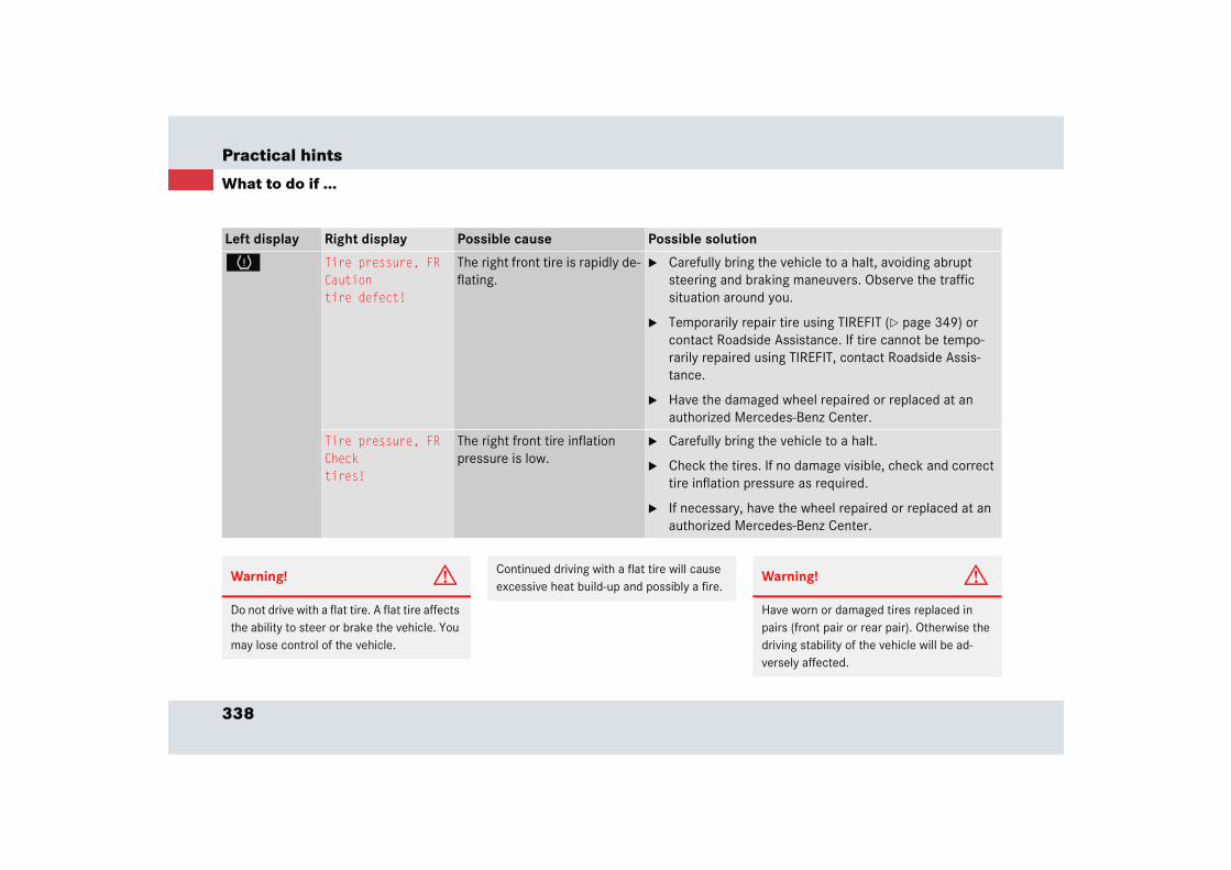
338
Practical hints
What to do if ...
Left display Right display Possible cause Possible solution
H Tire pressure, FRCautiontire defect!
The right front tire is rapidly de-flating.
� Carefully bring the vehicle to a halt, avoiding abrupt steering and braking maneuvers. Observe the traffic situation around you.
� Temporarily repair tire using TIREFIT (� page 349) or contact Roadside Assistance. If tire cannot be tempo-rarily repaired using TIREFIT, contact Roadside Assis-tance.
� Have the damaged wheel repaired or replaced at an authorized Mercedes-Benz Center.
Tire pressure, FRChecktires!
The right front tire inflation pressure is low.
� Carefully bring the vehicle to a halt.
� Check the tires. If no damage visible, check and correct tire inflation pressure as required.
� If necessary, have the wheel repaired or replaced at an authorized Mercedes-Benz Center.
Warning! G
Do not drive with a flat tire. A flat tire affects the ability to steer or brake the vehicle. You may lose control of the vehicle.
Continued driving with a flat tire will cause excessive heat build-up and possibly a fire.
Warning! G
Have worn or damaged tires replaced in pairs (front pair or rear pair). Otherwise the driving stability of the vehicle will be ad-versely affected.

339
Practical hints
What to do if ...
Left display Right display Possible cause Possible solution
A Reserve fuel The fuel level has fallen into the reserve range.
� Refuel at the next gas station (� page 240).
I Removekey!
You have forgotten to remove the SmartKey.
� Remove the SmartKey from the starter switch.
Replacekey
No additional code available for the SmartKey.
� Have the SmartKey checked. Notify an authorized Mercedes-Benz Center.
W Washer fluidCheck level!
The washer fluid level has dropped to about 1/3 of total reservoir capacity.
� Add washer fluid (� page 251).
N Closecenter compart.
The interior motion sensor is only activated when the stor-age compartment under the armrest is closed.
� Close the storage compartment under the armrest (� page 200).
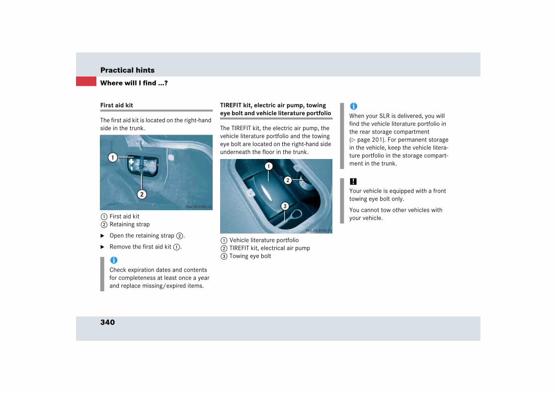
340
Practical hints
Where will I find ...?
First aid kit
The first aid kit is located on the right-hand side in the trunk.
1 First aid kit2 Retaining strap
� Open the retaining strap 2.
� Remove the first aid kit 1.
TIREFIT kit, electric air pump, towing eye bolt and vehicle literature portfolio
The TIREFIT kit, the electric air pump, the vehicle literature portfolio and the towing eye bolt are located on the right-hand side underneath the floor in the trunk.
1 Vehicle literature portfolio 2 TIREFIT kit, electrical air pump3 Towing eye bolt
iCheck expiration dates and contents for completeness at least once a year and replace missing/expired items.
iWhen your SLR is delivered, you will find the vehicle literature portfolio in the rear storage compartment (� page 201). For permanent storage in the vehicle, keep the vehicle litera-ture portfolio in the storage compart-ment in the trunk.
!Your vehicle is equipped with a front towing eye bolt only.
You cannot tow other vehicles with your vehicle.

341
Practical hints
Where will I find ...?
Compact guide (Canada only)
The compact guide is located in the rear storage compartment.
1 Storage compartment

342
Practical hints
Locking/unlocking in an emergency
Unlocking the vehicle
Unlocking the trunk
If you are unable to unlock the trunk with the SmartKey, open the trunk with the mechanical key.
The handle is located above the rear license plate recess.
1 Mechanical key locking tab2 Mechanical key
� Move locking tab 1 in the direction of arrow.
� Slide mechanical key 2 out of the housing.
Trunk lid lock
3 Unlocking
� Insert the mechanical key in the trunk lid lock.
� Perform the following two steps simul-taneously:
� Turn the mechanical key counterclockwise to the stop, to position 3.
� Pull the trunk lid handle and lift the trunk lid.
iUnlocking the trunk with the mechani-cal key will trigger the anti-theft alarm system when the door is opened.
To cancel the alarm, insert the SmartKey in the starter switch.
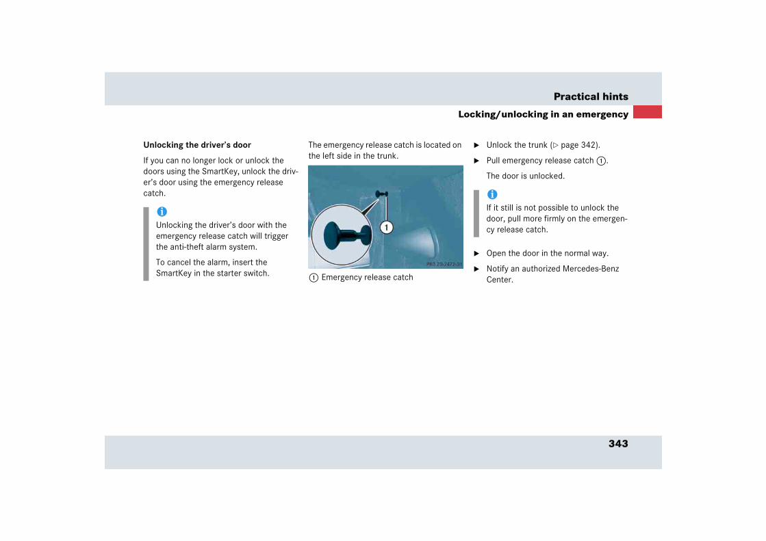
343
Practical hints
Locking/unlocking in an emergency
Unlocking the driver’s door
If you can no longer lock or unlock the doors using the SmartKey, unlock the driv-er’s door using the emergency release catch.
The emergency release catch is located on the left side in the trunk.
1 Emergency release catch
� Unlock the trunk (� page 342).
� Pull emergency release catch 1.
The door is unlocked.
� Open the door in the normal way.
� Notify an authorized Mercedes-Benz Center.
iUnlocking the driver’s door with the emergency release catch will trigger the anti-theft alarm system.
To cancel the alarm, insert the SmartKey in the starter switch.
iIf it still is not possible to unlock the door, pull more firmly on the emergen-cy release catch.
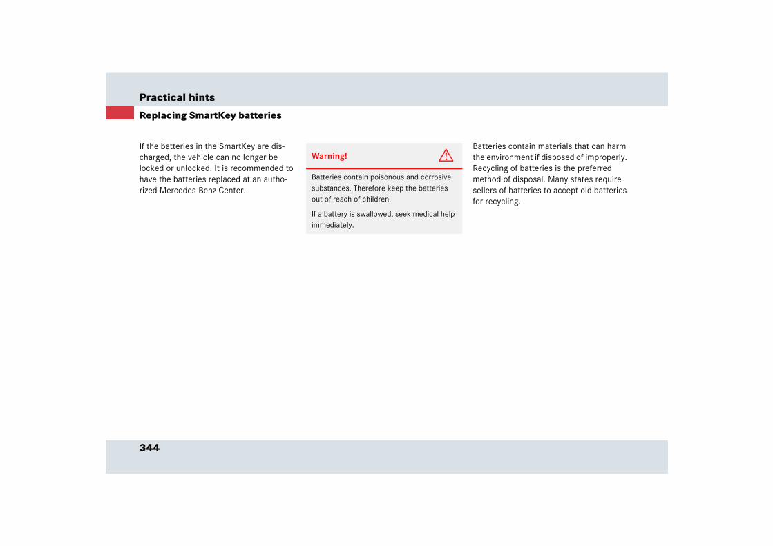
344
Practical hints
Replacing SmartKey batteries
If the batteries in the SmartKey are dis-charged, the vehicle can no longer be locked or unlocked. It is recommended to have the batteries replaced at an autho-rized Mercedes-Benz Center.
Batteries contain materials that can harm the environment if disposed of improperly. Recycling of batteries is the preferred method of disposal. Many states require sellers of batteries to accept old batteries for recycling.
Warning! G
Batteries contain poisonous and corrosive substances. Therefore keep the batteries out of reach of children.
If a battery is swallowed, seek medical help immediately.
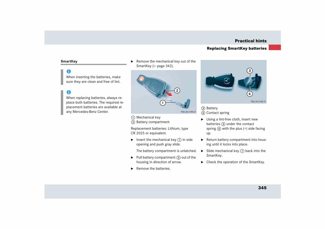
345
Practical hints
Replacing SmartKey batteries
SmartKey � Remove the mechanical key out of the SmartKey (� page 342).
1 Mechanical key2 Battery compartment
Replacement batteries: Lithium, type CR 2025 or equivalent.
� Insert the mechanical key 1 in side opening and push gray slide.
The battery compartment is unlatched.
� Pull battery compartment 2 out of the housing in direction of arrow.
� Remove the batteries.
3 Battery4 Contact spring
� Using a lint-free cloth, insert new batteries 3 under the contact spring 4 with the plus (+) side facing up.
� Return battery compartment into hous-ing until it locks into place.
� Slide mechanical key 1 back into the SmartKey.
� Check the operation of the SmartKey.
iWhen inserting the batteries, make sure they are clean and free of lint.
iWhen replacing batteries, always re-place both batteries. The required re-placement batteries are available at any Mercedes-Benz Center.
346
Practical hints
Replacing bulbs
Safe vehicle operation depends on proper exterior lighting and signaling. It is there-fore essential that all bulbs and lamp as-semblies are in good working order at all times.
Correct headlamp adjustment is extremely important. Have headlamps checked and readjusted at regular intervals and when a bulb has been replaced. See an authorized Mercedes-Benz Center for headlamp ad-justment.
iIf the headlamps are fogged up on the inside as a result of high humidity, driv-ing the vehicle a distance should clear up the fogging.
iSubstitute bulbs will be brought into use when lamps malfunction. Observe the messages in the multifunction dis-play (� page 323).
!You must not change the bulbs or LEDs yourself, as you could damage the vehi-cle lighting systems.
Have blown bulbs or LEDs replaced by an authorized Mercedes-Benz Center.
iIf one of the following bulbs blows, an-other bulb will adopt its function:
� Rear turn signals
� Brake lamps
� Side lamps
� Tail lamps
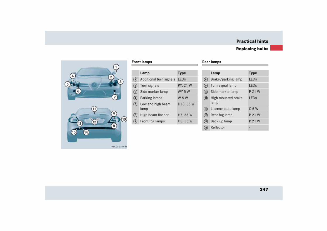
347
Practical hints
Replacing bulbs
Front lamps Rear lamps
Lamp Type
1 Additional turn signals LEDs
2 Turn signals PY, 21 W
3 Side marker lamp WY 5 W
4 Parking lamps W 5 W
5 Low and high beam lamp
D2S, 35 W
6 High beam flasher H7, 55 W
7 Front fog lamps H3, 55 W
Lamp Type
8 Brake/parking lamp LEDs
9 Turn signal lamp LEDs
a Side marker lamp P 21 W
b High mounted brake lamp
LEDs
c License plate lamp C 5 W
d Rear fog lamp P 21 W
e Back up lamp P 21 W
f Reflector -

348
Practical hints
Replacing the wiper blades
Removing wiper blades
� Remove the SmartKey from starter switch.
� Fold the wiper arm forward.
You must feel the wiper arm engage in position.
� Set the wiper blade at 90° to the wiper arm.
� Slide the wiper blade out in direction of arrow.
Installing wiper blades
� Position the wiper blade at 90° to the wiper arm.
� Slide the wiper blade onto the wiper arm.
� Fold the wiper blade parallel to the wiper arm.
� Fold the wiper arm backward to rest on the windshield. Make sure you hold on to the wiper when folding the wiper arm back.
Warning! G
For safety reasons, remove SmartKey from starter switch before replacing a wiper blade. Otherwise the motor could suddenly turn on and cause injury.
!The hood must be opened (� page 243) before folding the wiper arms away from the windshield. You could otherwise damage the hood and/or the wiper arm.
!Hold on to the wiper when folding the wiper arm back. If released, the force of the impact from the tensioning spring could crack the windshield.
Do not allow the wiper arms to contact the windshield glass without a wiper blade inserted.
Make sure the wiper blades is properly installed. Improperly installed wiper blades may cause windshield damage.
For your convenience, we recommend that you have this work carried out by an authorized Mercedes-Benz Center.
349
Practical hints
Flat tire
� Flat tireThe vehicle is equipped with the TIREFIT kit.
Preparing the vehicle
� Park the vehicle as far as possible from moving traffic on a hard surface.
� Turn on the hazard warning flashers.
� Turn the steering wheel so that the front wheels are in a straight ahead po-sition.
� Set the parking brake.
� Move the gear selector lever to P.
� Turn off the engine (� page 58).
� Remove the SmartKey from the starter switch.
� Open the driver’s door.
� Have any passenger exit the vehicle at a safe distance from the roadway.
Sealing tires with TIREFIT kit
Small tire punctures, particularly those in the tread, can be sealed with TIREFIT.TIREFIT can be used in ambient tempera-tures down to -4°F (-20°C). � Foreign objects (e.g. screws or nails)
should not be removed from the tire.
� Take TIREFIT, the sticker, and the elec-tric air pump out of the trunk.
!A wheel change should only be carried out at an authorized Mercedes-Benz Center. Otherwise there is a danger of damaging the vehicle by jacking it up incorrectly.
iOpen door only when conditions are safe to do so.
Warning! G
Keep TIREFIT away from sparks, open flame or heat source.
Do not smoke.
Warning! G
TIREFIT is a limited repair device. TIREFIT cannot be used for cuts or punctures larger than approximately 0.16 in (4 mm) and tire damage caused by driving with extremely low tire inflation pressure, or on a flat tire, or a damaged wheel.
Do not drive the vehicle under such circum-stances.
Contact your nearest Mercedes-Benz Center for assistance or call Roadside Assistance.
!After using TIREFIT, the tire inflation pressure sensor may have to be re-placed.
��
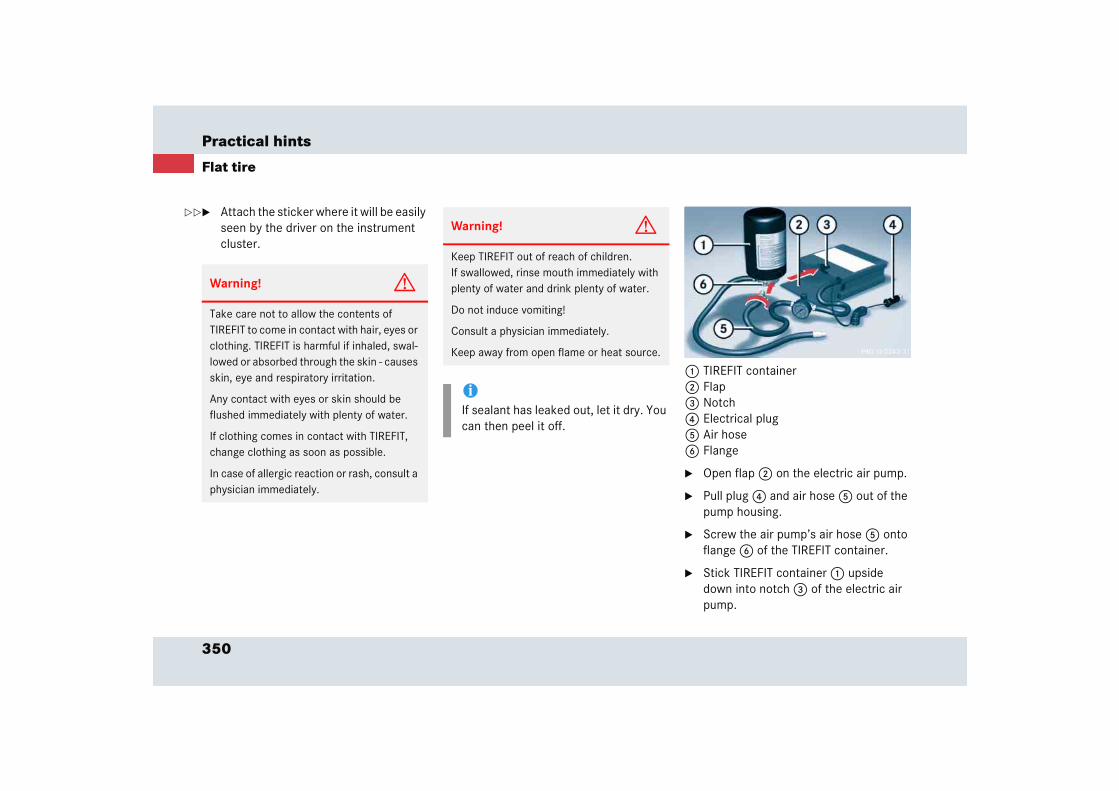
350
Practical hints
Flat tire
� Attach the sticker where it will be easily seen by the driver on the instrument cluster.
1 TIREFIT container2 Flap3 Notch4 Electrical plug5 Air hose6 Flange
� Open flap 2 on the electric air pump.
� Pull plug 4 and air hose 5 out of the pump housing.
� Screw the air pump’s air hose 5 onto flange 6 of the TIREFIT container.
� Stick TIREFIT container 1 upside down into notch 3 of the electric air pump.
Warning! G
Take care not to allow the contents of TIREFIT to come in contact with hair, eyes or clothing. TIREFIT is harmful if inhaled, swal-lowed or absorbed through the skin - causes skin, eye and respiratory irritation.
Any contact with eyes or skin should be flushed immediately with plenty of water.
If clothing comes in contact with TIREFIT, change clothing as soon as possible.
In case of allergic reaction or rash, consult a physician immediately.
Warning! G
Keep TIREFIT out of reach of children. If swallowed, rinse mouth immediately with plenty of water and drink plenty of water.
Do not induce vomiting!
Consult a physician immediately.
Keep away from open flame or heat source.
iIf sealant has leaked out, let it dry. You can then peel it off.
��
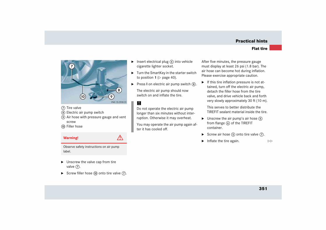
351
Practical hints
Flat tire
7 Tire valve8 Electric air pump switch9 Air hose with pressure gauge and vent
screwa Filler hose
� Unscrew the valve cap from tire valve 7.
� Screw filler hose a onto tire valve 7.
� Insert electrical plug 4 into vehicle cigarette lighter socket.
� Turn the SmartKey in the starter switch to position 1 (� page 40).
� Press I on electric air pump switch 8.
The electric air pump should now switch on and inflate the tire.
After five minutes, the pressure gauge must display at least 26 psi (1.8 bar). The air hose can become hot during inflation. Please exercise appropriate caution.
� If this tire inflation pressure is not at-tained, turn off the electric air pump, detach the filler hose from the tire valve, and drive vehicle back and forth very slowly approximately 30 ft (10 m).
This serves to better distribute the TIREFIT sealant material inside the tire.
� Unscrew the air pump’s air hose 5 from flange 6 of the TIREFIT container.
� Screw air hose 5 onto tire valve 7.
� Inflate the tire again.Warning! G
Observe safety instructions on air pump label.
!Do not operate the electric air pump longer than six minutes without inter-ruption. Otherwise it may overheat.
You may operate the air pump again af-ter it has cooled off.
��
352
Practical hints
Flat tire
� After attaining a tire inflation pressure of 26 psi (1.8 bar), press 0 on electric air pump switch 8.
The electric air pump should now be switched off.
� Turn the SmartKey in the ignition to position 0 (� page 40).
� Detach the electric air pump.
The air hose may still be hot. Please ex-ercise appropriate caution.
� Store the electrical plug and the air hose behind the flap and place the air pump back in the trunk.
� Close the trunk lid.
� Drive away immediately.
The TIREFIT sealant will distribute itself evenly inside the tire.
� After driving vehicle for an initial ten minutes, check tire inflation pres-sure using the pressure gauge on the air pump.
Warning! G
If a tire inflation pressure of 26 psi (1.8 bar) is not attained, tire is too severely damaged for TIREFIT to provide a reliable tire repair.
In this case, TIREFIT cannot properly seal the tire.
Do not drive the vehicle.
Contact the nearest Mercedes-Benz Center or call Roadside Assistance.
Warning! G
Do not exceed vehicle speed of 50 mph (80 km/h). A TIREFIT repair is not designed to operate at higher speeds.
The sticker must be attached on the instru-ment cluster where it will be easily seen by the driver.
Vehicle handling characteristics may change. Adapt your driving accordingly.
Warning! G
If tire inflation pressure has fallen below 20 psi (1.3 bar) do not continue to drive the vehicle.
Park your vehicle safely away from the road-way and contact the nearest authorized Mercedes-Benz Center or Roadside Assistance.
If tire inflation pressure is at least 20 psi (1.3 bar), inflate tire to correct pres-sure (see placards on driver’s door B-pillar or on fuel filler flap), and drive vehicle to nearest tire repair facility to have tire re-paired or replaced.
Recommended duration of use: 300 miles (500 km) at 50 mph (80 km/h) with the recommended tire inflation pressure.
��
353
Practical hints
Flat tire
� Visit an authorized Mercedes-Benz Center as soon as possible to obtain a new TIREFIT kit.
� Bring used TIREFIT materials to an au-thorized Mercedes-Benz Center for proper disposal.
� Replace your TIREFIT container every four years. Replacement containers are available at your authorized Mercedes-Benz Center.
Warning! G
Have worn or damaged tires replaced in pairs (front pair or rear pair). Otherwise the driving stability of the vehicle will be ad-versely affected.
Warning! G
Follow recommend tire inflation pressures.
Do not underinflate tires. Underinflated tires wear excessively and/or unevenly, adversely affect handling and fuel economy, and are more likely to fail from being over-heated.
Do not overinflate tires. Overinflated tires can adversely affect handling and ride comfort, wear unevenly, increase stopping distance, and result in sudden deflation (blowout) because they are more likely to become punctured or damaged by road debris, potholes etc.
Do not overload the tires by exceeding the specified load limit or vehicle capacity weight as indicated on the placard on the driver’s door B-pillar. Overloading the tires can overheat them, possibly causing a blowout.
Warning! G
Do not exceed vehicle speed of 50 mph (80 km/h). A TIREFIT repair is not designed to operate at higher speeds.
The sticker must be attached on the instru-ment cluster where it will be easily seen by the driver.
Vehicle handling characteristics may change. Adapt your driving accordingly.
354
Practical hints
Batteries
Your vehicle is equipped with two batter-ies:
� The starter battery (located in the trunk)
� The battery for electrical consumers (located in the trunk)
Warning! G
Failure to follow these instructions can re-sult in severe injury or death.
Never lean over batteries while connecting, you might get injured.
Observe all safety instructions and precau-tions when handling automotive batteries (� page 250).
Battery fluid contains sulfuric acid. Do not allow this fluid to come in contact with eyes, skin or clothing. In case it does, immediately flush affected area with water and seek medical help if necessary.
A battery will also produce hydrogen gas, which is flammable and explosive. Keep flames or sparks away from battery, avoid improper connection of jumper cables, smoking, etc.
!You must not jump start the vehicle, otherwise the vehicle electrical sys-tems could be damaged.
Only use the battery charge unit tested and approved by Mercedes-Benz for use on the SLR to charge the battery or maintain the battery charge. Using oth-er battery chargers may cause damage to the vehicle and/or personal injury.
Information on charging the batteries (� page 355).
Have the batteries checked regularly by an authorized Mercedes-Benz Center. Refer to Maintenance Booklet for maintenance intervals or contact an authorized Mercedes-Benz Center for further information.
If it is necessary to replace the batter-ies, notify an authorized Mercedes-Benz Center.
Warning! G
Do not place metal objects on the battery as this could result in a short circuit.
Use leak-proof batteries only to avoid the risk of acid burns in the event of an accident.

355
Practical hints
Batteries
Charging the batteries
You can obtain detailed information on charging the battery from your authorized Mercedes-Benz Center.
Warning! G
The brake system requires electrical power to operate.
A malfunction in the vehicle’s power supply or electrical system may impair brake sys-tem operation and switch it into its emer-gency operation mode. The same applies if battery is disconnected. To brake, the driver must then apply significantly greater brake pedal pressure and depress the pedal much further to obtain the expected braking ef-fect. If necessary, apply full pressure to the brake pedal. Brakes are only applied to the front wheels. Stopping distance is in-creased! Adjust your driving style according-ly. For more information, see “SBC brake system” (� page 84).
Warning! G
With a disconnected battery
� you will no longer be able to turn the SmartKey in the starter switch
� the gear selector lever will remain locked in position P
Warning! G
Never charge a battery while still installed in the vehicle unless the battery charge unit approved by Mercedes-Benz (supplied with your vehicle) is being used. Gases may es-cape during charging and cause explosions that may result in paint damage, corrosion or personal injury.
A battery charge unit specially adapted for Mercedes-Benz vehicles and tested and ap-proved by Mercedes-Benz is available, per-mitting the charging of the battery in its installed position. Contact an authorized Mercedes-Benz Center for information and availability. Charge battery in accordance with the separate operating instructions for the battery charger.
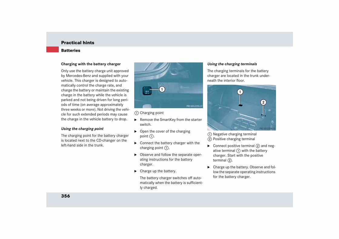
356
Practical hints
Batteries
Charging with the battery charger
Only use the battery charge unit approved by Mercedes-Benz and supplied with your vehicle. This charger is designed to auto-matically control the charge rate, and charge the battery or maintain the existing charge in the battery while the vehicle is parked and not being driven for long peri-ods of time (on average approximately three weeks or more). Not driving the vehi-cle for such extended periods may cause the charge in the vehicle battery to drop.
Using the charging point
The charging point for the battery charger is located next to the CD-changer on the left-hand side in the trunk.
1 Charging point
� Remove the SmartKey from the starter switch.
� Open the cover of the charging point 1.
� Connect the battery charger with the charging point 1.
� Observe and follow the separate oper-ating instructions for the battery charger.
� Charge up the battery.
The battery charger switches off auto-matically when the battery is sufficient-ly charged.
Using the charging terminals
The charging terminals for the battery charger are located in the trunk under-neath the interior floor.
1 Negative charging terminal2 Positive charging terminal
� Connect positive terminal 2 and neg-ative terminal 1 with the battery charger. Start with the positive terminal 2.
� Charge up the battery. Observe and fol-low the separate operating instructions for the battery charger.
357
Practical hints
Towing the vehicle
� Towing the vehicleMercedes-Benz recommends that the vehi-cle be transported with all wheels off the ground using flatbed or appropriate wheel lift/dolly equipment.
When circumstances do not permit the recommended towing methods, the vehi-cle may be towed with all wheels on the ground or front wheels raised only so far as
necessary to have the vehicle moved to a safe location where the recommended towing methods can be employed.
!Use flatbed or wheel lift/dolly equip-ment with SmartKey in starter switch turned to position 0.
Do not tow with sling-type equipment. Towing with sling-type equipment over bumpy roads will damage radiator and supports.
To prevent damage during transport, do not tie down vehicle by its chassis or suspension parts.
Switch off the tow-away alarm and the automatic central locking.
!If the vehicle is towed with the front axle raised, the engine must be shut off (SmartKey in starter switch position 0 or 1). Otherwise the ESP will immedi-ately be engaged and will apply the rear wheel brakes.
When towing the vehicle with all wheels on the ground, the gear selector lever must be in position N and the SmartKey must be in starter switch position 2.
When towing the vehicle with all wheels on the ground or the front axle raised, the vehicle may be towed only for dis-tances up to 30 miles (50 km) and at a speed not to exceed 30 mph (50 km/h).
!To be certain to avoid a possibility of damage to the transmission, however, we recommend the drive shaft be dis-connected at the rear axle drive flange for any towing beyond a short tow to a nearby garage.
358
Practical hints
Towing the vehicle
Warning! G
If circumstances require towing the vehicle with all wheels on the ground, always tow with a tow bar if:
� the engine will not run
� there is a malfunction in the SBC brake system
� there is a malfunction in the power sup-ply or in the vehicle’s electrical system
as that will be necessary to adequately con-trol the towed vehicle.
Prior to towing the vehicle with all wheels on the ground, make certain that the SmartKey is in starter switch position 2.
If the SmartKey is left in starter switch position 0 for an extended period of time, it can no longer be turned in the switch. In this case, the steering is locked. To unlock, re-move SmartKey from starter switch and re-insert.
iTo signal turns while being towed with the hazard warning flasher in use, turn SmartKey in starter switch to position 2 and activate the combina-tion switch for the left or right turn sig-nal in the usual manner – only the selected turn signal will operate.
Upon canceling the turn signal, the haz-ard warning flasher will operate again.
Warning! G
The brake system requires electrical power to operate.
A malfunction in the vehicle’s power supply or electrical system may impair brake sys-tem operation and switch it into its emer-gency operation mode. To brake, the driver must then apply significantly greater brake pedal pressure and depress the pedal much further to obtain the expected braking ef-fect. If necessary, apply full pressure to the brake pedal. Brakes are only applied to the front wheels. Stopping distance is in-creased! Adapt your driving style according-ly. For more information, see “SBC brake system” (� page 84).
With the engine not running, there is no power assistance for the brake and steering systems. In this case, it is important to keep in mind that a considerably higher degree of effort is necessary to brake and steer the ve-hicle. Adapt your driving accordingly.
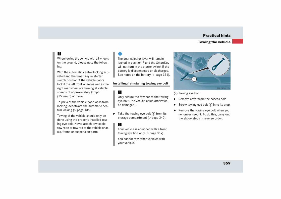
359
Practical hints
Towing the vehicle
Installing/reinstalling towing eye bolt
� Take the towing eye bolt 1 from its storage compartment (� page 340).
1 Towing eye bolt
� Remove cover from the access hole.
� Screw towing eye bolt 1 in to its stop.
� Remove the towing eye bolt when you no longer need it. To do this, carry out the above steps in reverse order.
!When towing the vehicle with all wheels on the ground, please note the follow-ing:
With the automatic central locking acti-vated and the SmartKey in starter switch position 2 the vehicle doors lock if the left front wheel as well as the right rear wheel are turning at vehicle speeds of approximately 9 mph (15 km/h) or more.
To prevent the vehicle door locks from locking, deactivate the automatic cen-tral locking (� page 135).
Towing of the vehicle should only be done using the properly installed tow-ing eye bolt. Never attach tow cable, tow rope or tow rod to the vehicle chas-sis, frame or suspension parts.
iThe gear selector lever will remain locked in position P and the SmartKey will not turn in the starter switch if the battery is disconnected or discharged. See notes on the battery (� page 354).
!Only secure the tow bar to the towing eye bolt. The vehicle could otherwise be damaged.
!Your vehicle is equipped with a front towing eye bolt only (� page 359).
You cannot tow other vehicles with your vehicle.
360
Practical hints
Towing the vehicle
Points to bear in mind
� The vehicle must not be tow-started.
� If the vehicle is to be towed, only tow it with all wheels on the ground.
� If the vehicle has suffered transmission damage, only tow it with the propeller shaft disconnected.
� Before towing the vehicle, make sure the battery is connected and charged. Otherwise you will not be able to switch on the ignition and move the selector lever to N. There will then be no power assistance when steering and braking.
Transporting the vehicle
The towing eye bolt can be used to pull the vehicle onto a trailer or transporter for transporting purposes.
� Move the selector lever to N.
!Due to the low clearance height of the SLR, care must be taken when loading and unloading from a transporter to avoid damaging the vehicle body work.
To secure the vehicle, only tie it down by the wheels or tires. Otherwise it could be damaged.
361
Practical hints
Fuses
� Fuses
!You must not change the fuses your-self, as you could damage the vehicle electrical systems.
Have fuses changed at an authorized Mercedes-Benz Center.
Technical data
Spare parts service
Warranty coverage
Identification labels
Layout of poly-V-belt drive
Engine
Rims and tires
Electrical system
Main dimensions
Weights
Fuels, coolants, lubricants, etc.
364
Technical data
The “Technical data” section provides the necessary technical data for your vehicle.
Spare parts service
All authorized Mercedes-Benz Centers maintain a stock of genuine Mercedes-Benz parts required for mainte-nance and repair work. In addition, strate-gically located parts distribution centers provide quick and reliable parts service.
More than 300 000 different spare parts for Mercedes-Benz models are available.
Mercedes-Benz genuine parts are subject-ed to stringent quality inspections. Each part has been specifically developed, man-ufactured or selected for and adapted to Mercedes-Benz vehicles.
Therefore, genuine Mercedes-Benz parts should be installed.
!The use of non-genuine Mercedes-Benz parts and accessories not authorized by Mercedes-Benz could damage the vehicle, which is not covered by the Mercedes-Benz Limited Warranty, or could compromise the vehicle’s dura-bility or safety.
365
Technical data
Warranty coverage
� Warranty coverageYour vehicle is covered under the terms of the warranties printed in the Service and Warranty Information booklet. Your authorized Mercedes-Benz Center will ex-change or repair any defective parts origi-nally installed in the vehicle in accordance with the terms of the following warranties:
� New Vehicle Limited Warranty
� Emission System Warranty
� Emission Performance Warranty
� California, Maine, Massachusetts and Vermont1 Emission Control System Warranty
Replacement parts and accessories are covered by the Mercedes-Benz Spare Parts and Accessories warranties, copies of which are available at any Mercedes-Benz Center.
Loss of Service and Warranty Information Booklet
Should you lose your Service and Warranty Information booklet, have an authorized Mercedes-Benz Center arrange for a re-placement. It will be mailed to you.
1 At time of printing, the decision regarding compli-ance with Vermont certification regulations was still pending. The vehicle may not be permitted to be registered in Vermont. Check with an authorized Mercedes-Benz Center for details.
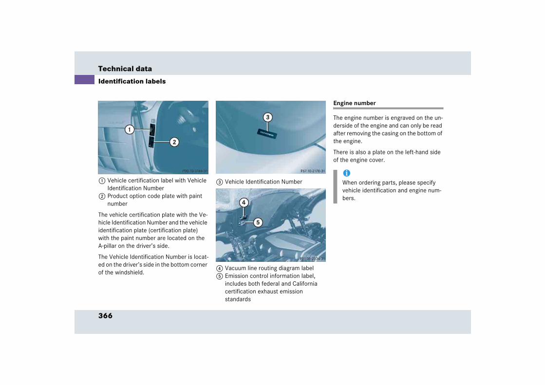
366
Technical data
Identification labels
1 Vehicle certification label with Vehicle Identification Number
2 Product option code plate with paint number
The vehicle certification plate with the Ve-hicle Identification Number and the vehicle identification plate (certification plate) with the paint number are located on the A-pillar on the driver’s side.
The Vehicle Identification Number is locat-ed on the driver’s side in the bottom corner of the windshield.
3 Vehicle Identification Number
4 Vacuum line routing diagram label5 Emission control information label,
includes both federal and California certification exhaust emission standards
Engine number
The engine number is engraved on the un-derside of the engine and can only be read after removing the casing on the bottom of the engine.
There is also a plate on the left-hand side of the engine cover.
iWhen ordering parts, please specify vehicle identification and engine num-bers.
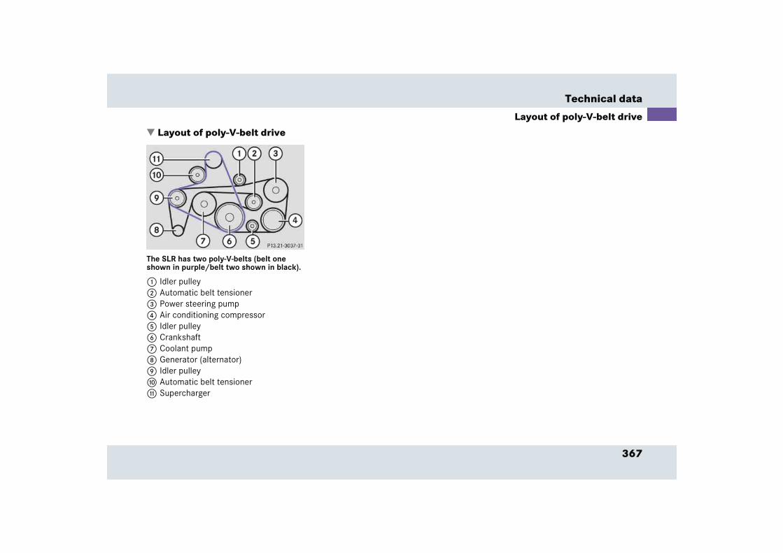
367
Technical data
Layout of poly-V-belt drive
� Layout of poly-V-belt drive
The SLR has two poly-V-belts (belt one shown in purple/belt two shown in black).
1 Idler pulley2 Automatic belt tensioner3 Power steering pump4 Air conditioning compressor5 Idler pulley6 Crankshaft 7 Coolant pump8 Generator (alternator)9 Idler pulleya Automatic belt tensionerb Supercharger
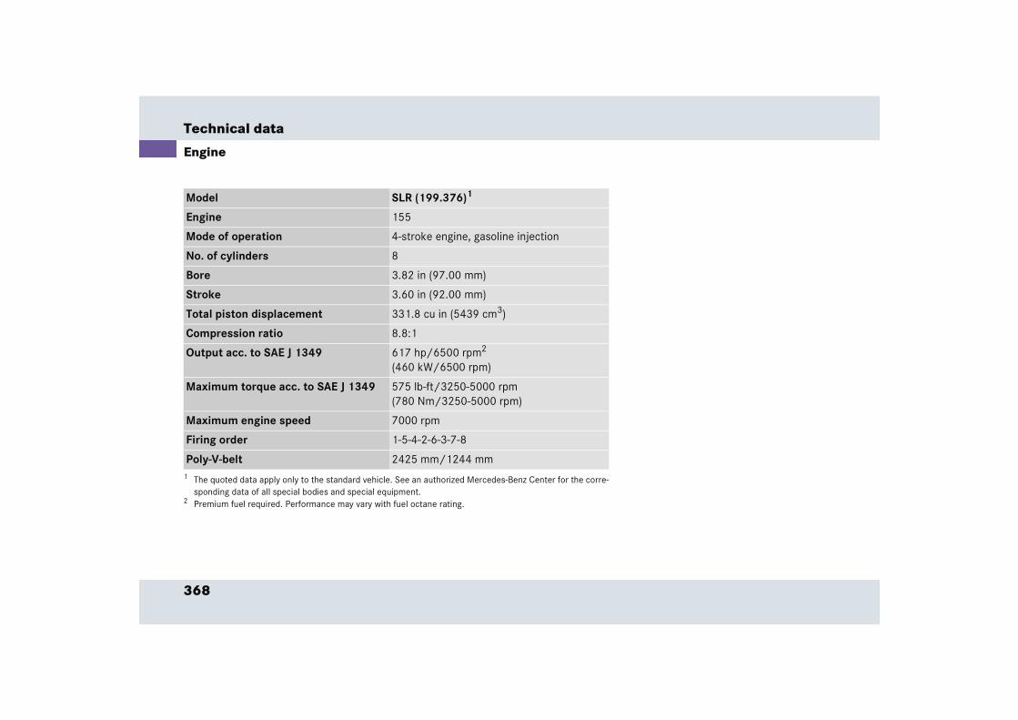
368
Technical data
Engine
Model SLR (199.376)1
1 The quoted data apply only to the standard vehicle. See an authorized Mercedes-Benz Center for the corre-sponding data of all special bodies and special equipment.
Engine 155
Mode of operation 4-stroke engine, gasoline injection
No. of cylinders 8
Bore 3.82 in (97.00 mm)
Stroke 3.60 in (92.00 mm)
Total piston displacement 331.8 cu in (5439 cm3)
Compression ratio 8.8:1
Output acc. to SAE J 1349 617 hp/6500 rpm2
(460 kW/6500 rpm)
2 Premium fuel required. Performance may vary with fuel octane rating.
Maximum torque acc. to SAE J 1349 575 lb-ft/3250-5000 rpm(780 Nm/3250-5000 rpm)
Maximum engine speed 7000 rpm
Firing order 1-5-4-2-6-3-7-8
Poly-V-belt 2425 mm/1244 mm

369
Technical data
Rims and tires
� Rims and tiresOnly use tires and rims which have been specifically developed for your vehicle and tested and approved by Mercedes-Benz. Other tires and rims can have detrimental effects, such as
� Poor handling characteristics
� Increased noise
� Increased fuel consumption
!Moreover, tires and rims not approved by Mercedes-Benz may, under load, exhibit dimensional variations and dif-ferent tire deformation characteristics that could cause them to come into contact with the vehicle body or axle parts. This may result in damage to the tires or the vehicle.
iFurther information on tires and rims is available at any authorized Mercedes-Benz Center. A placard with the recommended tire inflation pres-sures is located on the driver’s door B-pillar. Some vehicles may have sup-plemental tire pressure information for driving at high speeds (� page 263) or for vehicle loads less than the maxi-mum loaded vehicle condition. If such information is provided, it can be found on the placard located on the inside of the fuel filler flap. The tire pressure should be checked regularly and should only be adjusted on cold tires. Follow tire manufacturer’s mainte-nance recommendation included with vehicle.
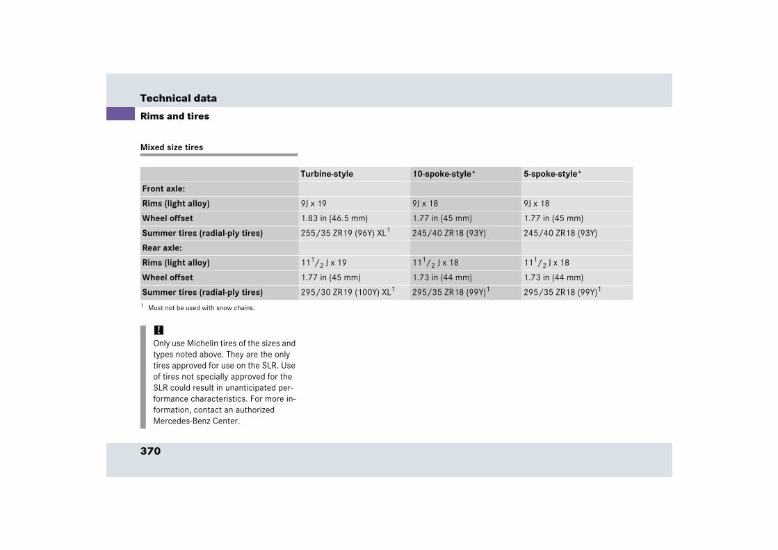
370
Technical data
Rims and tires
Mixed size tires
Turbine-style 10-spoke-style* 5-spoke-style*
Front axle:
Rims (light alloy) 9J x 19 9J x 18 9J x 18
Wheel offset 1.83 in (46.5 mm) 1.77 in (45 mm) 1.77 in (45 mm)
Summer tires (radial-ply tires) 255/35 ZR19 (96Y) XL1 245/40 ZR18 (93Y) 245/40 ZR18 (93Y)
Rear axle:
Rims (light alloy) 111/2 J x 19 111/2 J x 18 111/2 J x 18
Wheel offset 1.77 in (45 mm) 1.73 in (44 mm) 1.73 in (44 mm)
Summer tires (radial-ply tires) 295/30 ZR19 (100Y) XL1 295/35 ZR18 (99Y)1
1 Must not be used with snow chains.
295/35 ZR18 (99Y)1
!Only use Michelin tires of the sizes and types noted above. They are the only tires approved for use on the SLR. Use of tires not specially approved for the SLR could result in unanticipated per-formance characteristics. For more in-formation, contact an authorized Mercedes-Benz Center.
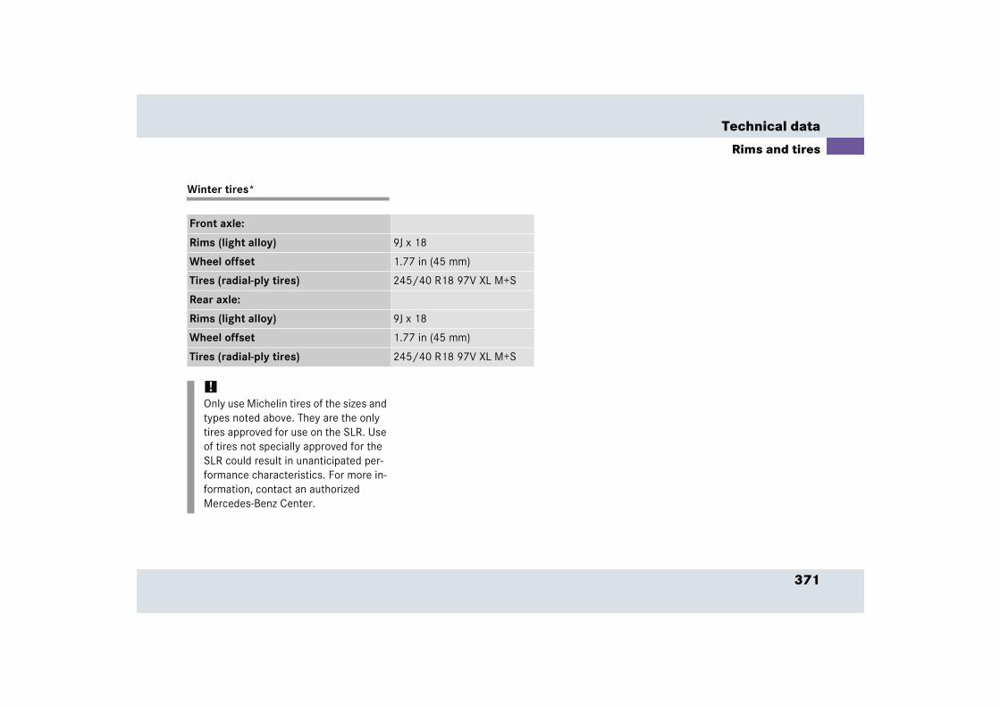
371
Technical data
Rims and tires
Winter tires*
Front axle:
Rims (light alloy) 9J x 18
Wheel offset 1.77 in (45 mm)
Tires (radial-ply tires) 245/40 R18 97V XL M+S
Rear axle:
Rims (light alloy) 9J x 18
Wheel offset 1.77 in (45 mm)
Tires (radial-ply tires) 245/40 R18 97V XL M+S
!Only use Michelin tires of the sizes and types noted above. They are the only tires approved for use on the SLR. Use of tires not specially approved for the SLR could result in unanticipated per-formance characteristics. For more in-formation, contact an authorized Mercedes-Benz Center.
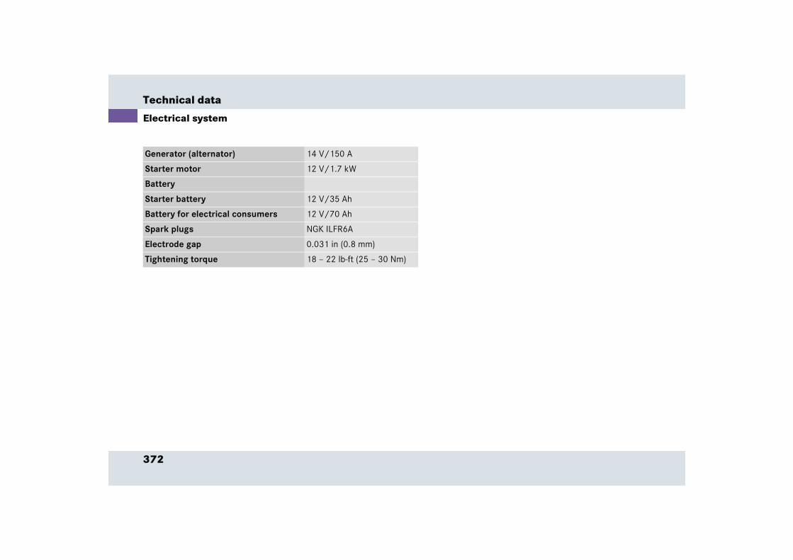
372
Technical data
Electrical system
Generator (alternator) 14 V/150 A
Starter motor 12 V/1.7 kW
Battery
Starter battery 12 V/35 Ah
Battery for electrical consumers 12 V/70 Ah
Spark plugs NGK ILFR6A
Electrode gap 0.031 in (0.8 mm)
Tightening torque 18 – 22 lb-ft (25 – 30 Nm)
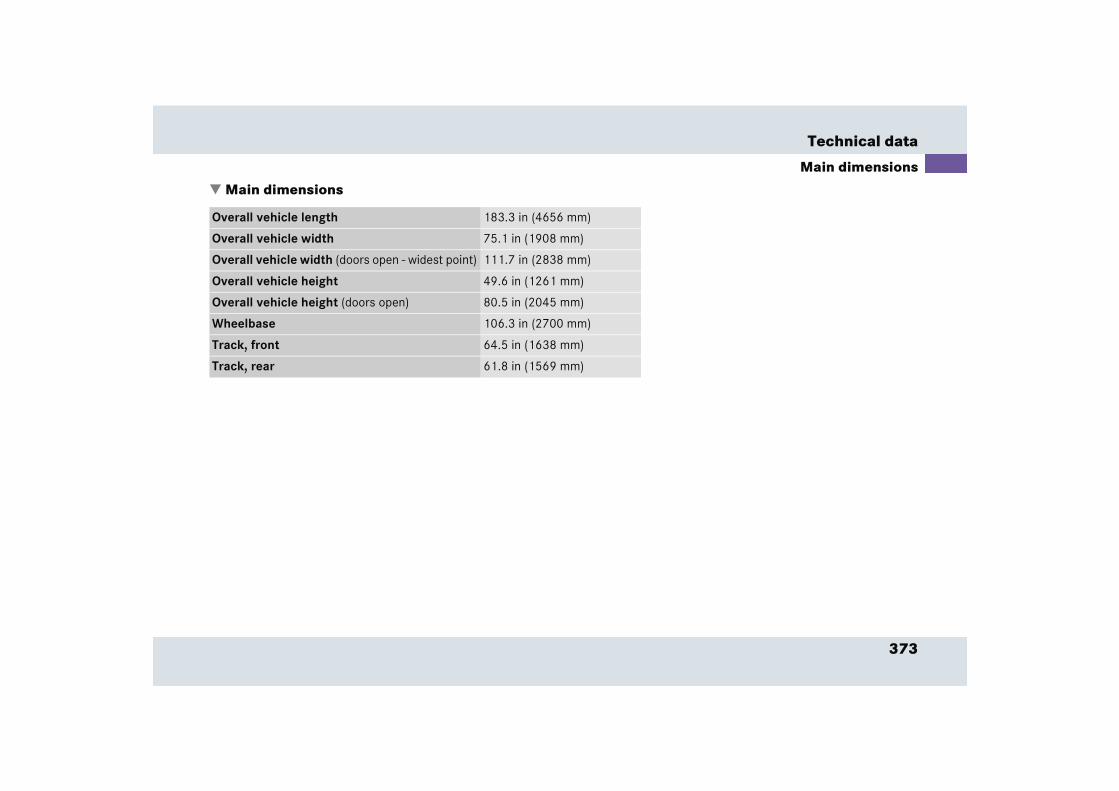
373
Technical data
Main dimensions
� Main dimensions
Overall vehicle length 183.3 in (4656 mm)
Overall vehicle width 75.1 in (1908 mm)
Overall vehicle width (doors open - widest point) 111.7 in (2838 mm)
Overall vehicle height 49.6 in (1261 mm)
Overall vehicle height (doors open) 80.5 in (2045 mm)
Wheelbase 106.3 in (2700 mm)
Track, front 64.5 in (1638 mm)
Track, rear 61.8 in (1569 mm)
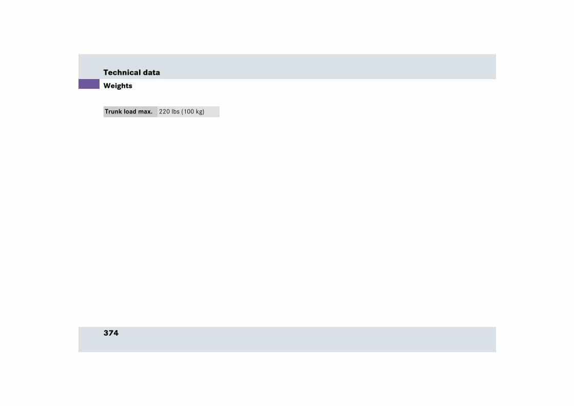
374
Technical data
Weights
Trunk load max. 220 lbs (100 kg)
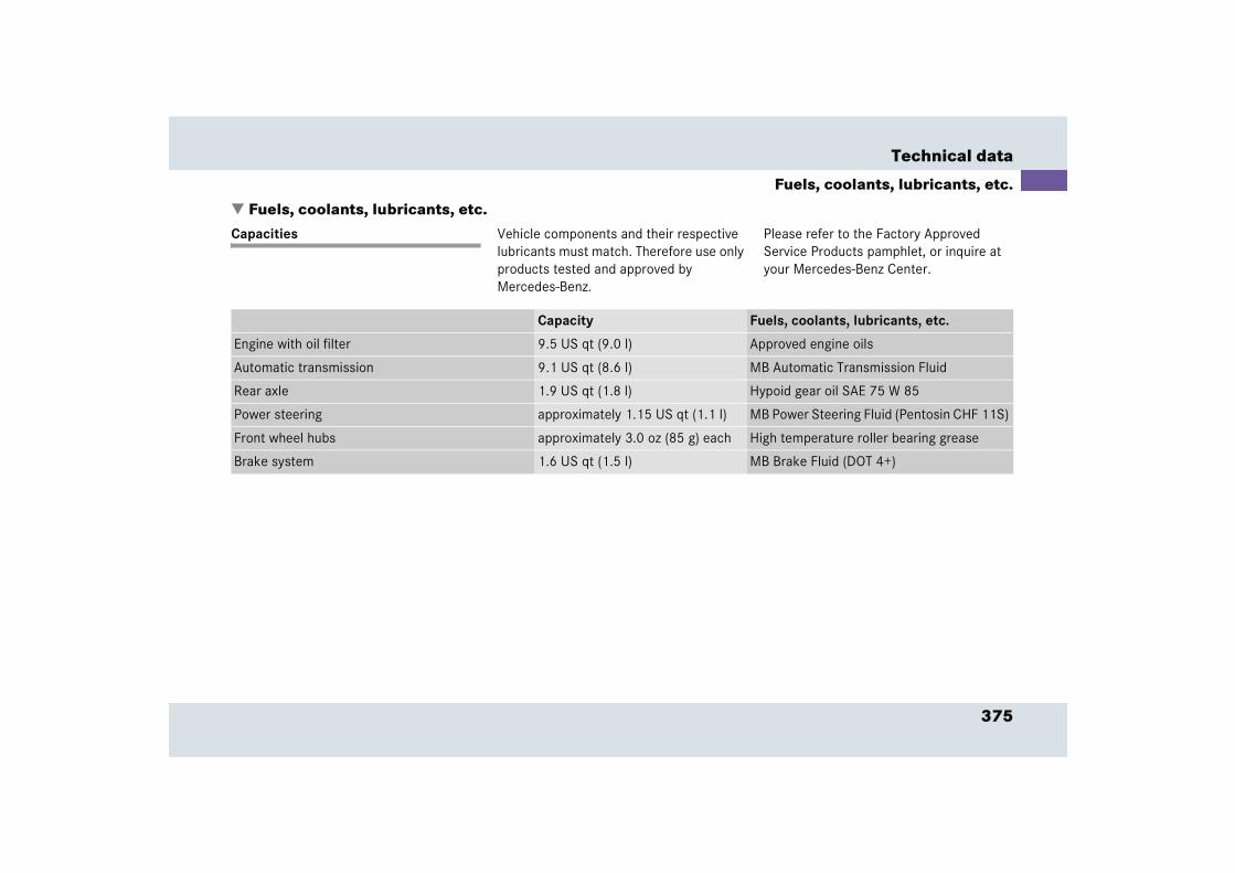
375
Technical data
Fuels, coolants, lubricants, etc.
� Fuels, coolants, lubricants, etc.Capacities Vehicle components and their respective
lubricants must match. Therefore use only products tested and approved by Mercedes-Benz.
Please refer to the Factory Approved Service Products pamphlet, or inquire at your Mercedes-Benz Center.
Capacity Fuels, coolants, lubricants, etc.
Engine with oil filter 9.5 US qt (9.0 l) Approved engine oils
Automatic transmission 9.1 US qt (8.6 l) MB Automatic Transmission Fluid
Rear axle 1.9 US qt (1.8 l) Hypoid gear oil SAE 75 W 85
Power steering approximately 1.15 US qt (1.1 l) MB Power Steering Fluid (Pentosin CHF 11S)
Front wheel hubs approximately 3.0 oz (85 g) each High temperature roller bearing grease
Brake system 1.6 US qt (1.5 l) MB Brake Fluid (DOT 4+)
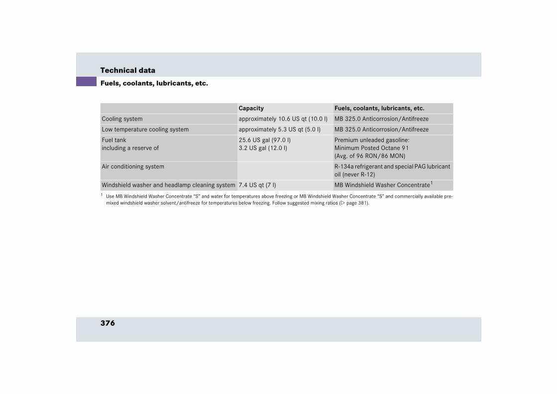
376
Technical data
Fuels, coolants, lubricants, etc.
Capacity Fuels, coolants, lubricants, etc.
Cooling system approximately 10.6 US qt (10.0 l) MB 325.0 Anticorrosion/Antifreeze
Low temperature cooling system approximately 5.3 US qt (5.0 l) MB 325.0 Anticorrosion/Antifreeze
Fuel tankincluding a reserve of
25.6 US gal (97.0 l)3.2 US gal (12.0 l)
Premium unleaded gasoline:Minimum Posted Octane 91(Avg. of 96 RON/86 MON)
Air conditioning system R-134a refrigerant and special PAG lubricant oil (never R-12)
Windshield washer and headlamp cleaning system 7.4 US qt (7 l) MB Windshield Washer Concentrate1
1 Use MB Windshield Washer Concentrate “S” and water for temperatures above freezing or MB Windshield Washer Concentrate “S” and commercially available pre-mixed windshield washer solvent/antifreeze for temperatures below freezing. Follow suggested mixing ratios (� page 381).
377
Technical data
Fuels, coolants, lubricants, etc.
Engine oils
Engine oils are specifically tested for their suitability in our engines and durability for our service intervals. Therefore, only use approved engine oils and oil filters required for vehicles with Maintenance System. For a listing of approved engine oils and oil filters, refer to the Factory Approved Service Products pamphlet, or contact an authorized Mercedes-Benz Center.
Using engine oils and oil filters of specification other than those expressly required for the Maintenance System, or changing of oil and oil filter at change intervals longer than those called for by the Maintenance System will result in en-gine damage not covered by the Mercedes-Benz Limited Warranty.
Please follow Maintenance System recom-mendations for scheduled oil changes. Failure to do so will result in engine dam-age not covered by the Mercedes-Benz Limited Warranty.
Engine oil additives
Do not blend oil additives with engine oil. They may damage the engine.
Damage or malfunctions resulting from blending oil additives are not covered by the Mercedes-Benz Limited Warranty.
Air conditioner refrigerant
R-134a (HFC) refrigerant and special PAG lubricating oil are used in the air condition-er system.
Never use R-12 (CFC) or mineral-based lu-bricating oil. Otherwise damage to the system will occur.
378
Technical data
Fuels, coolants, lubricants, etc.
Brake fluid
During vehicle operation, the boiling point of the brake fluid is continuously reduced through the absorption of moisture from the atmosphere. Under extremely strenu-ous operating conditions, this moisture content can lead to the formation of bub-bles in the system, thus reducing the sys-tem’s efficiency.
Therefore, the brake fluid must be re-placed every two years, preferably in the spring.
Only brake fluid approved by Mercedes-Benz is recommended. Your au-thorized Mercedes-Benz Center will pro-vide you with additional information.
Premium unleaded gasoline Fuel requirements
Only use premium unleaded fuel:
� The octane number (posted at the pump) must be 91 min. It is an average of both the Research (R) octane num-ber and the Motor (M) octane number: (R+M)/2). This is also known as the ANTI-KNOCK INDEX.
Unleaded gasoline containing oxygenates such as ethanol, IPA, IBA and TBA can be used provided the ratio of any one of these oxygenates to gasoline does not exceed 10%; MTBE must not exceed 15%.
The ratio of methanol to gasoline must not exceed 3% plus additional cosolvents.
!To maintain the engine’s durability and performance, premium unleaded gaso-line must be used. If premium unleaded is not available and low octane fuel is used, follow these precautions:
� have the fuel tank only partially filled with unleaded regular and fill up with premium unleaded as soon as possible
� avoid full throttle driving and abrupt acceleration
� do not exceed an engine speed of 3000 rpm if the vehicle is loaded with a light load such as two per-sons and no luggage
� do not exceed 2/3 of maximum ac-celerator pedal position if the vehi-cle is fully loaded or operating in mountainous terrain
379
Technical data
Fuels, coolants, lubricants, etc.
Using mixtures of ethanol and methanol is not allowed. Gasohol, which contains 10% ethanol and 90% unleaded gasoline, can be used.
These blends must also meet all other fuel requirements, such as resistance to spark knock, boiling range, vapor pressure, etc.
Gasoline additives
A major concern among engine manufacturers is carbon build-up caused by gasoline. Mercedes-Benz recommends only the use of quality gasoline containing additives that prevent the build up of carbon deposits.
After an extended period of using fuels without such additives, carbon deposits can build up especially on the intake valves and in the combustion area, leading to engine performance problems such as:
� Warm-up hesitation
� Unstable idle
� Knocking/pinging
� Misfire
� Power loss
In areas where carbon deposits may be encountered due to lack of availability of gasolines which contain these additives, Mercedes-Benz recommends the use of additives approved by us for use on Mercedes-Benz vehicles. Refer to Factory Approved Service Products pamphlet for a listing of approved product(s). Follow directions on product label.
Do not blend any specific fuel additives with fuel. This only results in unnecessary cost and may be harmful to engine operation.
Damage or malfunction resulting from poor fuel quality or from blending additional fuel additives other than those tested and approved by us for use on Mercedes-Benz vehicles listed in the Factory Approved Service Products pamphlet are not covered by the Mercedes-Benz Limited Warranty.
380
Technical data
Fuels, coolants, lubricants, etc.
Coolants
The engine coolant is a mixture of water and anticorrosion/antifreeze, which pro-vides:
� corrosion protection
� freeze protection
� boiling protection (by increasing the boiling point)
The cooling system was filled at the factory with a coolant providing freeze protection to approximately -22°F (-30°C) and corro-sion protection.
If the antifreeze mixture is effective to -22°F (-30°C), the boiling point of the cool-ant in the pressurized cooling system is reached at approximately 266°F (130°C).
The coolant solution must be used year round to provide the necessary corrosion protection and increase in the boil-over protection. Refer to Service Booklet for re-placement interval.
Coolant system design and coolant used determine the replacement interval. The replacement interval published in the Service Booklet is only applicable if MB 325.0 anticorrosion/antifreeze solu-tion or other Mercedes-Benz approved products of equal specification (see Facto-ry Approved Service Products pamphlet) are used to renew the coolant concentra-tion or bring it back up to the proper level.
To provide important corrosion protection, the solution must be at least 45% anticor-rosion/antifreeze (equivalent to freeze protection to approximately - 22°F [-30°C]). If you use a solution that is more than 55% anticorrosion/antifreeze (freeze protection to approximately - 49°F [-45°C]), the engine temperature will increase due to the lower heat transfer capability of the solution. Therefore, do not use more than this amount of anticorro-sion/antifreeze.
If the coolant level is low, water and MB 325.0 anticorrosion/antifreeze should be used to bring it up to the proper level (have cooling system checked for signs of leakage). Please make sure the mixture is in accordance with label instructions.
The water in the cooling system must meet minimum requirements, which are usually satisfied by normal drinking water. If you are not sure about the water quality, con-sult an authorized Mercedes-Benz Center.
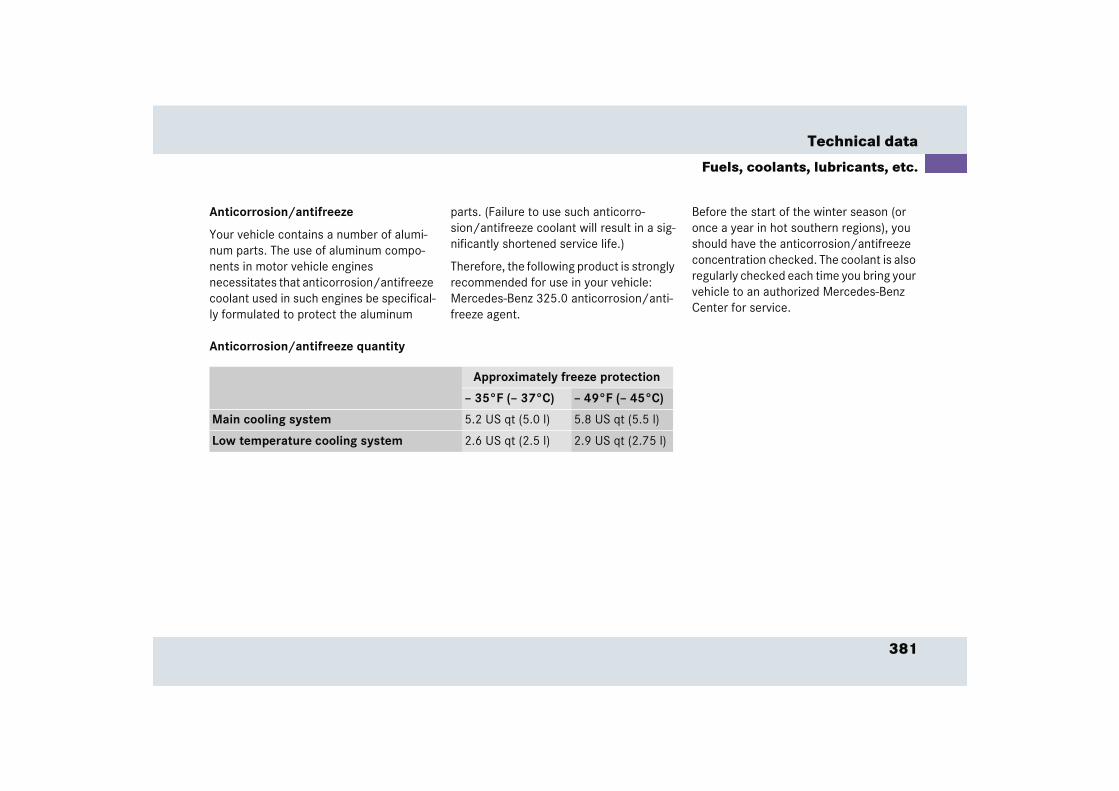
381
Technical data
Fuels, coolants, lubricants, etc.
Anticorrosion/antifreeze
Your vehicle contains a number of alumi-num parts. The use of aluminum compo-nents in motor vehicle engines necessitates that anticorrosion/antifreeze coolant used in such engines be specifical-ly formulated to protect the aluminum
parts. (Failure to use such anticorro-sion/antifreeze coolant will result in a sig-nificantly shortened service life.)
Therefore, the following product is strongly recommended for use in your vehicle: Mercedes-Benz 325.0 anticorrosion/anti-freeze agent.
Before the start of the winter season (or once a year in hot southern regions), you should have the anticorrosion/antifreeze concentration checked. The coolant is also regularly checked each time you bring your vehicle to an authorized Mercedes-Benz Center for service.
Anticorrosion/antifreeze quantity
Approximately freeze protection
– 35°F (– 37°C) – 49°F (– 45°C)
Main cooling system 5.2 US qt (5.0 l) 5.8 US qt (5.5 l)
Low temperature cooling system 2.6 US qt (2.5 l) 2.9 US qt (2.75 l)
382
Technical data
Fuels, coolants, lubricants, etc.
Windshield and headlamp washer system
Both the windshield and headlamp washer systems are supplied from the windshield washer fluid reservoir.
The windshield and headlamp washer fluid reservoir has a capacity of approximately 7.4 US qt (7 l).
� Refill the reservoir with MB Windshield Washer Concentrate and water (or con-centrate and commercially available premixed windshield washer sol-vent/antifreeze, depending on ambient temperatures).
Windshield and headlamp washer fluid mixing ratio
For temperatures above “freezing point”, use MB Windshield Washer Concentrate “S” and water:
� 1 part “S” to 100 parts water
(1.34 floz [40 ml] “S” to 1 gallon [4.0 l] wa-ter).
For temperatures below “freezing point” use MB Windshield Washer Concentrate “S” and commercially available premixed windshield washer solvent/antifreeze:
� 1 part “S” to 100 parts solvent
(1.34 floz [40 ml “S” to 1 gallon [4.0 l] sol-vent).
Warning! G
Washer solvent/antifreeze is highly flamma-ble. Do not spill washer solvent/antifreeze on hot engine parts because it may ignite and burn. You could be seriously burned.

383

Technical terms

385
Technical terms
ABS(Anti-lock Braking System)Prevents the wheels from locking up during braking so that the vehicle can continue to be steered.
Accessory weight(� page 278)
ACL(Airbrake/Central Locking)Controls the locking mechanism of the Airbrake and the central locking sys-tem.
Air pressure(� page 278)
Aspect ratio(� page 278)
BabySmartTM1 airbag deactivation system
This system detects if a special system compatible child restraint seat is in-stalled on the front passenger seat. The system will automatically deactivate the passenger front airbag when such a seat is properly installed (PASSENGER AIRBAG OFF warning lamp on the lower centre console lights up).
BabySmartTM compatible child seatsSpecial restraint system for children. The sensor system for the passenger seat prevents deployment of the pas-senger front airbag if a BabySmartTM compatible child seat is installed. See an authorized Mercedes-Benz Center for availability.
Bar(� page 278)
BAS(Brake Assist System)System for potentially reducing braking distances in emergency braking situa-tions. The system is activated when it senses an emergency based on how fast the brake is applied.
Bead(� page 278)
Bi-Xenon headlampsHeadlamps which use an electric arc as the light source and produce a more in-tense light than filament headlamps. Bi-Xenon headlamps produce low beam and high beam.
CAC(Customer Assistance Center)Mercedes-Benz customer service cen-ter, which can help you with any ques-tions about your vehicle and provide assistance in the event of a break-down.
1 BabySmartTM is a trademark of Siemens Automotive Corp.

386
Technical terms
CAN system(Controller Area Network)Data bus network serving to control ve-hicle functions such as door locking or windshield wiping depending on vehi-cle settings and/or ambient condi-tions.
CockpitAll instruments, switches, buttons and indicator/warning lamps in the passen-ger compartment needed for vehicle operation and monitoring.
Cold tire inflation pressure(� page 278)
Control systemThe control system is used to call up vehicle information and to change component settings. Information and messages appear in the multifunction display. The driver uses the buttons on the multifunction steering wheel to navigate through the system and to ad-just settings.
Cruise controlDriving convenience system for auto-matically maintaining the vehicle speed set by the driver.
Curb weight(� page 278)
DOT(Department of Transportation)(� page 279)
Engine numberThe number set by the manufacturer and placed on the cylinder block to uniquely identify each engine pro-duced.
Engine oil viscosityMeasure of the internal oil friction (vis-cosity) at different temperatures. The higher the temperature the oil can tol-erate without thinning too much, or the lower the temperature it can tolerate without thickening too much, the bet-ter the viscosity characteristics of the oil.
ESP(Electronic Stability Program)Improves vehicle handling and direc-tional stability.
ETD(Emergency Tensioning Device)Device which deploys in certain frontal and rear collisions exceeding the sys-tem's threshold to tighten the seat belts. ->SRS
GAWR(Gross Axle Weight Rating)(� page 279)
Gear rangeNumber of gears which are available to the automatic transmission for shifting. The automatic gear shifting process can be adapted to specific operating conditions using the gear selector le-ver.

387
Technical terms
GPS(Global Positioning System)Satellite-based system for relaying geographic location information to and from vehicles equipped with special re-ceivers. Employs CD digital maps for navigation.
GVW(Gross Vehicle Weight)(� page 279)
GVWR(Gross Vehicle Weight Rating)(� page 279)
Head-thorax airbagInstalled in the doors, these airbags protect occupants during side impact collisions exceeding a preset thresh-old. Unlike normal side airbags, head-thorax airbags are also designed to provide protection for the head area.
Instrument clusterThe displays and indicator/warning lamps in the driver’s field of vision, in-cluding the tachometer, speedometer, engine temperature and fuel gauge.
KickdownDepressing the accelerator past the point of resistance shifts the transmis-sion down to the lowest possible gear. This very quickly accelerates the vehi-cle and should not be used for normal acceleration needs.
Kilopascal (kPa)(� page 279)
Maximum load rating(� page 279)
Maximum loaded vehicle weight(� page 279)
Maximum tire inflation pressure(� page 279)
MON(Motor Octane Number)The Motor Octane Number for gasoline as determined by a standardized method. It is an indication of a gaso-line's ability to resist undesired detona-tion (knocking). The average of both the MON (Motor Octane Number) and RON (Research Octane Number) is posted at the pump, also known as ANTI-KNOCK INDEX.
Multifunction displayTwo display fields in the instrument cluster used to present information provided by the control system.
Multifunction steering wheelSteering wheel with buttons for operat-ing the control system.
Normal occupant weight(� page 279)
388
Technical terms
Overspeed rangeEngine speeds within the red marking on the tachometer dial. Avoid this en-gine speed range, as it may result in se-rious engine damage that is not covered by the Mercedes-Benz Limited Warranty.
Poly-V-belt driveDrives engine-components (alternator, AC compressor, etc.) from the engine.
Power trainCollective term designating all compo-nents used to generate and transmit motive power to the drive axles, includ-ing
� engine
� clutch/torque converter
� transmission
� transfer case
� drive shaft
� differential
� axle shafts/axles
Production options weight(� page 279)
Program mode selector switchUsed to switch the automatic transmis-sion between sport operation (S), com-fort operation (C) and manual operation (MAN).
PSI(Pounds per square inch)(� page 280)
Recommended tire inflation pressure(� page 280)
REST(Residual Engine Heat Utilization)Feature that uses the engine heat stored in the coolant to heat the vehi-cle interior for a short time after the en-gine has been turned off.
Rim(� page 280)
RON(Research Octane Number)The Research Octane Number for gaso-line as determined by a standardized method. It is an indication of a gaso-line's ability to resist undesired detona-tion (knocking). The average of both the MON (Motor Octane Number) and RON (Research Octane Number) is posted at the pump, also known as ANTI-KNOCK INDEX.
SBC brake system(Sensotronic Brake Control)Electronically controlled hydraulic braking system for increased braking safety and comfort.
Shift lockWhen the vehicle is parked, this lock prevents the gear selector lever from being inadvertently moved out of posi-tion P without SmartKey turned and brake pedal depressed.
389
Technical terms
Sidewall(� page 280)
SRS(Supplemental Restraint System) Seat belts, emergency tensioning de-vice and airbags. Though independent systems, they are closely interfaced to provide effective occupant protection.
Tele Aid(Telematic Alarm Identification on De--mand)The Tele Aid system consists of three types of response: automatic and man-ual emergency, roadside assistance and information. Tele Aid is initially ac-tivated by completing a subscriber agreement and placing an acquain-tance call. The Tele Aid system is operational pro-vided that the vehicle’s battery is charged, properly connected, not dam-aged and cellular and GPS coverage is available.
Tightening torqueForce times lever arm (e.g. a lug wrench) with which threaded fasteners such as wheel bolts are tightened.
TIN(Tire Identification Number)(� page 280)
Tire load rating(� page 280)
Tire ply composition and material used(� page 280)
Tire speed rating(� page 280)
TIREFIT kitAccessory for emergency and tempo-rary tire repair. The TIREFIT kit consists of a container with sealant material, a filler hose and an air compressor.
Traction(� page 280)
Tread(� page 280)
Treadwear indicators(� page 280)
Uniform Tire Quality Grading Standards(� page 281)
Vehicle capacity weight(� page 281)
Vehicle maximum load on the tire(� page 281)
VIN(Vehicle Identification Number)The number set by the manufacturer and placed on the body to uniquely identify each vehicle produced.

Index
391
Index
AABS 79, 385
Indicator lamp 29, 297Messages in the multifunction
display 306ABS/ESP
Warning lamp 29, 296Accelerator position, automatic
transmission 173Accessory weight 278Accident
In case of 55ACL 385
Messages in the multifunction display 308
ActivatingAir circulation mode 188Air conditioning (cooling) 192Anti-theft alarm system 91Central locking (control system) 135ESP 84Exterior headlamps 51Exterior lamps 106Headlamps 51High beams 109Immobilizer 58, 90
Manual gearshift program 175Rear window defroster 181Residual heat 190Tow-away alarm 92Windshield wipers 53
AddingCoolant 249Engine oil 248
Additional turn signals (exterior mirror) 347
AdjustingAir distribution 187Air volume 186Mirrors 43Seat angle 42Seat fore and aft 42Seat height 42Seats 41Steering column height 43Steering column length 43Steering wheel 42
Air conditioner refrigerant 377Air conditioning (cooling)
Turning off 192Turning on 192
Air pressure 278
Air pressure see Tire inflation pressureAir recirculation mode 188Air volume adjustment 186Airbags 63
Children 64Front 68Head-thorax 68, 69Knee 68Passenger 68
Airbrake 31, 87Automatic mode 89Emergency braking 89Manual mode 88Message in the multifunction
display 318Test Mode 88Warning lamp 29, 301
AlarmAudible 78, 90Canceling 91, 93Visual 90
Anticorrosion/antifreeze 376, 381Antiglare
Automatic 179

392
Index
Anti-theft alarm system 90Arming 91Canceling alarm 91Disarming 91
Anti-theft deviceDust cover 224
Anti-theft systemsAnti-theft alarm system 90Tow-away alarm 91
Anti-theft wheel nuts 282Fitting 283Removing 283
Aquaplaning see HydroplaningAshtray 202Aspect ratio 278AUDIO menu 122
Operating CD player 123Selecting radio station 123
Audio system 31, 143Audio and telephone, operation 143Button and soft key operation 146Cassette operation 152CD operation 156Location 143Operating and display elements 144Operating safety 143
Operation 146Radio operation 149Switching off 146Switching on 146Telephone operation 160
Auto-dimming for interior rear view mirror 179
AutomaticInterior lighting control 111
Automatic car wash 290Automatic central locking
Activating/deactivating (control system) 135
Automatic climate control 31, 182Adjusting air distribution 187Adjusting air volume 185, 186Air recirculation 188Center air vents 31Deactivating 191Defrosting the windshield 188MAXCOOL 187Residual heat utilization 190Side air vents 31Temperature sensor 33
Automatic headlamp mode 106
Automatic transmission 167Accelerator position 173Emergency operation (Limp Home
Mode) 177Fluid level 248Gear ranges 170Gear selector lever 167Gear selector lever position 167, 171Gear shifting malfunctions 177Kickdown 173Manual shifting 168One-touch gearshifting 168Shift program mode selector
switch 173Steering wheel gearshift control 174Towing 360Transmission fluid 248
Automatic transmission fluid 248
393
Index
BBabySmartTM
Self-test 75BabySmartTM airbag deactivation
system 75, 385BabySmartTM compatible child
seats 385Back up lamp 347Bar 278BAS 79, 81, 385BAS/ESP
Indicator lamp 296Batteries, SmartKey
Check lamp 99Replacing 344
Batteries, vehicle 250Charging 355Consumer battery 250, 354Maintenance 354Messages in the multifunction
display 310Starter battery 250
Battery charger 356Bead 278
Bi-Xenon headlamps 385Body surface 289Brake fluid 375, 378
Checking 241Brake lamp
High mounted 347Brake pads
Messages in the multifunction display 317
Brake warning lamp 29, 298Brake/parking lamp 347Brakes 230Break-in period 228Bulbs
Changing 346Front 347Messages in the multifunction
display 323Rear 347
ButtonAudio system 146
CCAC 385CAN system 386Capacities
Fuels, coolants, lubricants etc. 375Cargo area see TrunkCassette operation
Playing cassettes 152Catalytic converter 237CD changer 156
Loading/unloading a CD magazine 157
Location 157CD operation 156CD player
Operating 123Cellular phone
Delayed switch-off time 205Inserting the cradle 205Making calls in hands-free mode 207Making calls in private mode 206Re-inserting 206Removing the cradle 204
394
Index
Center air vents 31Center console
Lower part 32Upper part 31
Center storage compartment 201Centigrade
Setting temperature units 129Central locking
Automatic 103Central locking switch 31, 103Switching on/off (control
system) 135Unlocking from inside 103
ChangingBulbs 346CDs 156
Charging the batteries (vehicle) 355Battery charger 356
CheckingBrake fluid 241Coolant level 241, 249Engine oil level 241Tire inflation pressure 242Vehicle lighting 242Washer reservoir level 242
Child safetyAirbags 64Automatic child seat recognition 75Infant and child restraint systems 62
Cigarette lighter 202Cleaning
Headlamps 178, 293Vehicle 290Windows 292Windshield 53Wiper blades 291
Cleaning tires 255Clearing
Service display 286Clock 128Closing
Hood 246Trunk lid 102Windows 193, 194Windows with SmartKey 195
Cockpit 26, 386Cold tire inflation pressure 278Combination switch 27, 51, 109
High beam flasher 51Windshield wipers 52
ComfortShift program mode 173
Compact guide 341Control and operation of radio
transmitters 237
395
Index
Control system 117, 386AUDIO menu 122Display digital speedometer 122Functions 119, 121Instrument cluster submenu 128Lighting submenu 130Menus 120, 121Multifunction display 117Multifunction steering wheel 118Selecting radio system 123Settings menu 125Standard display menu 117, 122Submenus 119, 121TEL menu 138Trip computer menu 136Vehicle submenu 134
Coolant 249, 380Adding 249Anticorrosion/antifreeze
quantity 381Checking level 249Messages in the multifunction
display 320
Temperature 239Temperature gauge 114Topping up 249Warning lamp 29, 300
Coolant levelChecking 241, 249Messages in the multifunction
display 319Cooling see Air conditioningCourtesy lighting 112Cruise control 197, 386
Canceling 198Driving downhill 198Driving uphill 198Fine adjustment 199Lever 27, 197Setting current speed 198Setting speeds 199
Curb weight 278Customer Assistance Center 385
DDaytime running lamp mode 107
Setting 131Deactivating
Air conditioning (cooling) 192Air recirculation mode 189Alarm 91Anti-theft alarm system 91Automatic climate control 191Central locking (control system) 135Cruise control 198Engine with the SmartKey 58ESP 83Exterior lamps 106Exterior lamps delayed shut-off 132Headlamps 57Immobilizer 90Interior light delayed switch-off 134Interior lighting delayed shut-off 134Manual gearshift program 177Rear window defroster 181Residual heat 190Tow-away alarm 92
396
Index
Deep water see Standing waterDefroster
Rear window 181Defrosting the windshield 188Delayed shut-off
Exterior lamps 132Interior lighting 134
Delayed switch-offInterior lighting 134
Delayed switch-off timeCellular phone 205
Department of Transportation see DOTDifferential
Message in the multifunction display 322
DifficultiesWhile driving see Problems while driv-
ingWith starting 49
Digital speedometer 122Direction of rotation (tires) 256Display elements
Audio system 144
DisplaysDigital speedometer 122Maintenance service indicator 286Showing vehicle status
messages 124Vehicle status messages 304
Distance to empty (range)Calling up 138
DoorHandle 34Message in the multifunction
display 318Opening 100Opening from the inside 100Opening from the outside 100Opening in an emergency 343Unlocking from the outside 98
DOT 279Downhill driving
Cruise control 198Downshifting 168Drinking and driving 229
Driving 45, 50Driving abroad 236Hydroplaning 234In winter 235Problems 54Safety systems 79Through standing water 236
Driving abroad 236Driving hints
SBC brake system 86Driving instructions 229Driving off 232Driving safety systems 79
ABS 79BAS 81ESP 81SBC brake system 84
Driving systems 197Cruise control 197
Driving tips 173Dust cover 222
Slipping on/off 223
397
Index
EElectric air pump 340Electrical consumer battery 250Electrical outlet see 12-V socket 203Electronic Stability Program see ESPEmergency
Opening the driver’s door 343Opening the trunk 342Unlocking the vehicle 342
Emergency call911 164
Emergency call systemInitiating emergency call 210Requirements 208
Emergency operation (Limp Home Mode) 177
Emergency operationsReleasing trunk lid from inside 102
Emergency Tensioning Device (ETD) 72, 386
Emission control 238Emission control information label 366
EngineCompartment 243Power output 368Starting 48Technical data 368Turning off 58
Engine malfunction indicator lamp 29Engine number 366, 386Engine oil 246, 377
Adding 248Additives 377Checking 247Checking level 241Consumption 246Filler neck 247Message in the multifunction
display 330Viscosity 386
Engine oil temperature 29Oil temperature symbol 301
Engine start button 31
Entry/exit lights 111ESP 79, 81, 386
Control switch 32Messages in the multifunction
display 307Resetting 307Switching off 83Switching on 84Warning lamp 81
ETD see Emergency Tensioning DeviceExpress-open windows 194Exterior lamp switch 27, 51, 105Exterior lamps
Delayed shut-off 132Exterior lighting
Additional turn signals 347Exterior rear view mirrors
Adjusting 32, 43
398
Index
FFahrenheit
Setting temperature units 129Fastening the seat belts 45Fine adjustment
Cruise control 199First aid kit 340Fitting
Anti-theft wheel nuts 283Flat tire 349
TIREFIT kit 349Floormat
Driver’s side 221Installing 221Removing 221
Fog lamp, rear 347Switching on 109
Fog lamps, front 347Switching on 108
Front airbags 68Front bulbs 347Front lamps
Switching on 105
FuelAdditives 379Gasoline additives 379Premium unleaded gasoline 376,
378Requirements 378Reserve warning 29
Fuel consumption statisticsAfter start 137Since last reset 137
Fuel filler flap 240Locking 240Unlocking 240
Fuel requirements 378Fuel reserve
Message in the multifunction display 339
Warning lamp 301Fuel system
Message in the multifunction display 329
Fuel tankFiller flap 240
Fuels, coolants, lubricants etc. 375Functions (control system) 119, 121Fuses 361
GGarage door opener 33, 215Gasoline 240GAWR 279Gear range
Automatic transmission 170Limiting 170Shifting into optimal 169
Gear range limitCanceling 169
Gear selector lever 32, 167Lock 48, 388Position 171Position (automatic
transmission) 167Gearshift
Indicator lamp 29Gearshift program
Manual 173, 175Global
Locking 98Unlocking 98
399
Index
GPS 387Gross Axle Weight Rating see GAWRGross Vehicle Weight Rating see GVWRGross Vehicle Weight see GVWGVW 279GVWR 279
HHands-free microphone 33
Telephone 33Hazard warning flasher 31, 110Headlamp cleaning system 251Headlamp shut-off delay see Delayed
shut-off, exterior lampsHeadlamps
Automatic control 106Cleaning 293Cleaning system 178, 251Refilling washer fluid 251Switching off 57Switching on 51
Head-thorax airbag 75, 387
HeightSeat 42
High beam flasher 51, 109, 347High beam headlamp indicator 29High beam headlamps
Switching on 109High mounted brake lamp 347High-pressure cleaners 290Hood 243
Closing 246Messages in the multifunction
display 318Opening 243
Horn 27Hydroplaning 234
400
Index
IIdentification labels
Emission control information label 366
Vacuum line routing diagram label 366
Ignition 40Immobilizer 90
Activating 90Deactivating 90
Infant and child restraint systems 72Installing 77
InstallingInfant and child restraint systems 77Towing eye bolt 359Wiper blades 348
Instrument cluster 28, 113, 387Coolant temperature gauge 114Illumination 113Multifunction display 117Outside temperature indicator 115Select language 130
Instrument lighting 113Interior lighting 33, 111
Automatic control 111Delayed shut-off 134Delayed switch-off 134Manual operation 112
Interior rear view mirrorAdjusting 43
Interior storage spaces 200
JJump starting 354
KKey, SmartKey
Battery check lamp 98Factory setting 98Loss of 100Opening 38Positions in starter switch 40Remote control 96Replacing the battery 344Turning off the engine 58
Kickdown 173, 387Kilometers/miles in speedometer 129Kilopascal 279Knee airbags 68

401
Index
LLamps
Exterior 346Lamps, indicator and warning
ABS 29, 297ABS/ESP 29, 296Airbrake 29, 301BAS/ESP 296Battery (SmartKey) 98Brake warning lamp 29, 298CHECK ENGINE 29Coolant 300Coolant level 29Engine oil 29ESP 81Fuel reserve 29, 301Gearshift 29High beam 29Maintenance service indicator 286Manual gearshift 301PASSENGER AIRBAG OFF 303SBC 84Seat belt 29, 302SRS 29, 63, 302Turn signal 29
LanguageMultifunction display 130
License plate illumination 347Light
Sensor 328Lighting
Automatic headlamp mode 106Combination switch 109Daytime running lamp mode 107Exterior lamp switch 105Front fog lamps 108High beams 109Instruments 113Interior 111Locator lighting 108Low beam 105Manual headlamp mode 106Night security illumination 108Parking lamps 105Rear fog lamp 109Settings (control system) 130Standing lamps 105
Limiting the gear range 170Limp Home Mode 177Loading terminology 278Loading the vehicle 256Location
Audio system 143Compact guide (Canada only) 341Telephone 201
Locator lighting 108, 132Locking 56
Automatic while driving 103Centrally from inside 103Fuel filler flap 240Global, SmartKey 98
Loss ofKeys 100Service and Warranty Information
Booklet 365Low and high beam lamp 347

402
Index
MMain dimensions 373Main odometer 29Maintenance 286, 354Maintenance service
Overdue 287Types 287When due 286
Maintenance service indicator 286Calling up 288Clearing 288
Making a telephone call 30Making calls
Hands-free mode 207Private mode 206
MANGearshift program 173
ManualShift program mode 173
Manual gearshiftWarning lamp 301
Manual gearshift program 175Activating 175Deactivating 177Downshifting 176Selecting 176Upshifting 177
Manual headlamp mode 106Manual operation
Interior lighting control 112Manually
Opening the driver’s door 343Opening the trunk 342
Map pocket in passenger footwell 200Maximum cooling MAXCOOL 187Maximum inflation pressure 279Maximum load rating 279Maximum loaded vehicle weight 279Mechanical key 342Menus 119
AUDIO 122In control system 120, 121Settings menu 125Standard display 122Submenus 119TEL 138Trip computer 136Vehicle status message memory 124
403
Index
MessagesABS 306ACL malfunction 308Airbrake 318Battery (vehicle) 310Brake pads 317Bulbs 323Coolant 320Coolant level 319Differential 322Doors 318Engine oil 330ESP 307Fuel system 329Hood 318Parking brake 316Reserve fuel 339SBC brake system 312Seat belt 318SmartKey 339Storage compartment under the
armrest 339TeleAid 309Tire 331Trunk lid 318Washer fluid 339
Miles/kilometers in speedometer 129Mirrors 43, 179
Auto-dimming for interior rear view mirror 179
Exterior rear view mirror 43Interior rear view mirror 43
MON 240, 387Mph or km/h in speedometer 129Multifunction display 117, 387
Left 29Right 29Selecting language 130Standard display 117
Multifunction steering wheel 30, 118, 387
Buttons 118
NNight security illumination 108
Setting 132Normal occupant weight 279
OOccupant distribution 279Occupant safety
Children and airbags 64Octane number 388Oil see Engine oilOne-touch gearshifting 168
Canceling gear range limit 169Downshifting 168Upshifting 169
OpeningDoor from the inside 100Door from the outside 100Driver’s door in an emergency 343Hood 243Trunk 99Trunk from the inside 101Trunk in an emergency 342Vehicle in an emergency 342Windows 193, 194Windows with SmartKey 195With the key 38
404
Index
OperatingAudio system 143CD player 123Radio 123Radio transmitters 237Telephone 138, 143, 160
Operating safetyAudio system 143
Operating systemVehicle status message memory 124
Operator’s manual 340Overdue maintenance service 287Overhead control panel 33Overspeed range 388
PPaint number 366Panic alarm 78
Panic button on SmartKey 78Parcel net in trunk 201Parking 56, 232Parking brake 32
Engaging 56Message in the multifunction
display 316Releasing 49
Parking lamps 347PASSENGER AIRBAG OFF
Warning lamp 303Passenger compartment 236Passenger side
Front airbag 68Head-thorax airbag 69Knee airbag 68
Pedals 229Performance enhancement system
Airbrake 87
Phone book 141Loading 141Quick search 141
Phone numberDialing 141Redialing 142
PlayingCDs 157
Poly-V-belt drive 388Layout 367
Potential problems associated with under-inflated and overinflated tires 267
Power assistance 230Power train 388Power washer 290Power windows 193
Synchronizing 196Problems
While driving 54With the vehicle 21
Production options weight 279Program mode selector switch 388PSI 280

405
Index
QQuick search
Phone book 141
RRadio
Selecting stations 123Station search 123Station selection setting 135
Radio operation 149Radio see Radio operationRadio transmitters, control and
operation 237Range (distance to empty)
Calling up 138Reactivating
Automatic climate control 191Reading lamp 33Rear
Storage compartment 201Rear bulbs 347
Rear fog lampSwitching on 109
Rear lamps see Tail lampsRear view mirrors see MirrorsRear window defroster 181Rear-view mirror 33Recommended inflation pressure 280Redial memory 142Refueling 240Refuelling
Unleaded premium grade gasoline 240
Regular checks 241Remote control
SmartKey 96Removing
Anti-theft wheel nuts 283Replacing
Battery (SmartKey) 344Wiper blades 348
ResettingAll functions (control system) 126ESP 307Fuel consumption 138Maintenance service indicator 288Trip odometer 115
Residual heat utilization 190Restraint system see Infant and child re-
straint systemsRestraint systems 62
Airbags 62, 63Child seat recognition 62Child seats 62Emergency Tensioning Device
(ETD) 62, 72Seat belts 62, 69
Rim 280RON 240, 388Roof rack 225
406
Index
SSafety systems
Driving 79SBC brake system 79, 84, 388
Activation 85Deactivation 86Driving hints 86Emergency operating mode 84Messages in the multifunction
display 312Self-check 85, 317Warning lamp 84
SeatAngle 42Fore and aft 42Height 42
Seat belt force limiter 72Seat belts 45, 62
Message in the multifunction display 318
Telltale 302Seating capacity 258
SelectingManual gearshift program 176
Self-testBabySmartTM airbag deactivation
system 75Sensor
Light 328Service
Calling up the due date 287Service life (tires) 254Service see MaintenanceSetting
Cruise control 198Current speed 198Daytime running lamp mode 131Higher speed in cruise control 199Hours (clock) 128Individual vehicle settings 125Instrument lighting 113Interior lighting delayed shut-off 134Interior lighting delayed
switch-off 134
Lamps and lighting (control system) 130
Locator lighting 132Lower speed in cruise control 199Miles/kilometers in
speedometer 129Minutes (clock) 128Multifunction display language 130Night security illumination 132Speed in cruise control 199Speedometer display mode 129Station selection mode 135Temperature (interior) 185Temperature indicator 129Time display mode 129Tire inflation pressure units 136Units
Temperature 129Tire inflation pressure 136
Units in speedometer 129
407
Index
SettingsFactory (SmartKey) 98Menus and submenus 119Resetting all (control system) 126Selective, SmartKey 98
Settings menuFunctions in 125Individual vehicle settings 125Submenus 126
Shift program modeComfort 173Manual 173Sport 173
Shift program mode selector switchAutomatic transmission 173
ShiftingGear selector lever 167Gear selector lever positions 171Into optimal gear range (automatic
transmission) 169Side air vents 31Side marker lamp
Rear 347
Side windowsCleaning 292
Sidewall 280Simultaneous wiping and washing
Windshield wipers 53Single wipe 53Slipping on/off
Dust cover 223SmartKey 96
Checking the batteries 99Global locking 98Global unlocking 98Messages in the multifunction
display 339Opening and closing the windows
with 195Restoring to factory setting 99Selective setting 98Unlocking the trunk lid 99
Snow chains 285Soft keys
Audio system 146Spare parts service 364
SpeedSetting current 198
Speed settingsCruise control 199
SpeedometerSetting units 129
SportShift program mode 173
SRS 389Indicator lamp 29, 302
Standing waterDriving instructions 236
Start button 48Starter battery 250, 354Starter switch 27, 40Starting difficulties 49Starting the engine 48Steering column
Height adjustment 43Length adjustment 43
Steering wheel 42Adjusting 42Buttons 30
408
Index
Steering wheel gearshift controlAutomatic transmission 174Warning lamp 301
Storage compartmentArmrest 200Center 201Rear 201
Storage compartments 200Message in the multifunction
display 339Storing tires 255Submenus
For settings 119In control system 121Instrument cluster 128Lighting 130Resetting functions 126Selecting 126Settings menus 126Vehicle 134
Sun visors 180
Switching offAudio system 146Automatic central locking (control
system) 135Delayed (exterior lamps) 132Engine 58Hazard warning flasher 110Headlamps 57
Switching onAudio system 146Automatic central locking (control
system) 135ESP 84Front fog lamps 108Hazard warning flasher 110Headlamps 51High beams 109Rear fog lamp 109Windshield wipers 53
SymbolEngine oil temperature 301
SynchronizingPower windows 196
TTachometer
Displaying gear range 170Overspeed range 115
Technical data 362Electrical system 372Engine 368Engine power output 368Fuels, coolants, lubricants etc. 375Main dimensions 373Poly-V-belt 367Rims and tires 369Weights 374Windshield and headlamp washer
system 382Tele Aid 207, 389
Emergency call button 33Emergency calls 209Information 212Initiating an emergency call
manually 210Messages in the multifunction
display 309Roadside Assistance 211SOS button 210Tele Aid system 208

409
Index
Telephone 203Answering a call 140Dialing 141Ending a call 141Hands-free microphone 33Loading phone book 141Operating 138Operation 160Redialing 142Signal strength 139Storage location 201
TemperatureOutside temperature indicator 115Sensor 33Setting interior temperature 185Setting units in display 129Tires 263
Tightening torque 389Time
Setting hours 128Setting minutes 128
Time display modeSetting 129
TIN 280Tire
Vehicle maximum load on 281Tire and Loading Information 257Tire and loading terminology 278Tire care and maintenance 254Tire Identification Number see TINTire inflation pressure 351
Checking 242, 262, 264Checking manually 264Setting units 136
Tire inspection 254Tire load rating 280Tire ply composition and material
used 280Tire speed rating 234, 271, 280Tire terminology 278Tire traction 234TIREFIT kit 340, 349, 389
Using 349Tires 253
Direction of rotation 256Driving instructions 233Message in the multifunction
display 331Retreads 253Rims and tires 369Rotating 281Service life 254Temperature 263, 277Tread depth 255, 284Wear pattern 281Winter* 284
410
Index
Topping upCoolant 249Engine oil 248
Tow-away alarm 91Arming 92Canceling alarm 93Disarming 92Disarming for transport 92Switch 32
Towing 357Transmission damage 360
Towing eye bolt 340Installing/reinstalling 359
Traction 173, 280Transmission
Damage 360Transporting 360Traveling abroad 236Tread 280Tread depth 255Tread depth (tires) 284Treadwear indicators 280Trip computer 136
Trip odometerResetting 115
TrunkClosing the lid 102Opening 99Opening from inside vehicle 101Opening in an emergency 342Parcel net 201Trunk lid emergency release 102
Trunk lamp 112Trunk lid
Closing 102Emergency release 102Message in the display 318
Trunk lid rack 225Trunk lock 101Turn signals 27, 52
Front 347Indicator lamps 29Rear 347
Turning offEngine 58
UUniform Tire Quality Grading
Standards 281Units
Setting speedometer units 129Setting temperature units 129Setting tire inflation pressure
units 136Unlocking 38
Centrally from inside 103Driver’s doors in an emergency 343Fuel filler flap 240Global 98Selective settings 98Trunk in an emergency 342
Uphill drivingCruise control 198
Upshifting 169
411
Index
Useful features12-V socket 203Ashtray and cigarette lighter 202Dust cover 222Floormats 221Garage door opener 215Map pocket in passenger
footwell 200Parcel net in trunk 201Storage compartments 200Tele Aid 207Telephone 203
VVacuum line routing diagram label 366Vehicle
Cleaning 290Individual settings 125Locking 31Towing 357Transporting 360Unlocking 31Unlocking in an emergency 342
Vehicle capacity weight 281Vehicle care 290
Window cleaning 292Wiper blades 291
Vehicle Identification Number 366
Vehicle lightingChecking 242
Vehicle literature portfolio 340Vehicle loading terminology 278Vehicle maximum load on the tire 281Vehicle status message memory
Calling up 124Clearing 125
Vehicle status messagesDisplaying 124
Vehicle status messages in the multifunc-tion display 304
Ventilation and residual heat 190VIN (vehicle identification number) 389
412
Index
WWarning sounds
Driver’s seat belt 69Parking brake 50
Warranty coverage 365Washer fluid
Message in the multifunction display 339
Washer reservoir levelChecking 242
Washing the vehicle 289Wear pattern (tires) 281Wheels
Tires and wheels 253
WindowsAutomatic opening 194Closing 193, 194, 195Closing fully 194Closing with SmartKey 195Express-open 194Opening 193, 194, 195Opening fully 194Opening with SmartKey 195Stopping 195Synchronizing power windows 196
Windows see Side windowsWindshield
Refilling washer fluid 251Washer fluid 251Windshield and headlamp washer
system 382Windshield washer fluid
Refilling 251Wiping with 53
Windshield wipers 27, 52Fast wiper speed 53Replacing the wiper blades 348Single wipe 53Switching on 53Wiping with windshield washer
fluid 53Winter driving
Snow chains 285Tires* 284
Winter driving instructions 235Winter tires* 284Wiper blade
Replacing 348Wiper blades
Cleaning 291Wiping
Interval 53With windshield washer fluid 53

413

Order No. 6515 4801 13 Part No. 199 584 14 81 USA Edition A 2005
Service and Literature
Your authorized Mercedes-Benz Center has trained technicians and original Mercedes-Benz parts to service your vehicle properly. For expert advice and quality service, see an authorized Mercedes-Benz Center.
If you are interested in obtaining service literature for your vehicle, please contact an authorized Mercedes-Benz Center. We consider this the best way for you to obtain accurate information for your vehicle.
For further information you can find us on the Mercedes-Benz web-site www.mbusa.com or www.mercedes-benz.ca.
We reserve the right to modify the technical details of the vehicle as given in the data and illustrations of this Operator’s Manual. Reprinting, translation and copying, even of excerpts, is not permitted without our prior authorization in writing.
Press time June 28, 2004GSP/TIP
Printed in Germany
Warning! G
To help avoid personal injury, be extremely careful when performing any service work or repairs. Improper or incomplete service or the use of incorrect or inappropriate parts or materials may damage the vehicle or its equipment, which may in turn result in personal injury.
If you have any questions about carrying out any type of service, turn to the advice of an authorized Mercedes-Benz Center.