Embed Size (px)
Citation preview
7/29/2019 Slop Deflection
http://slidepdf.com/reader/full/slop-deflection 1/14
University of Ottawa Fall 2013
CVG 4148 – Theory of Structures II
Theory of Structures II
CVG 4148
Instructor: A. Abdulridha
Slop Deflection Method
CVG 4148 – Theory of Structures II Slop Deflection-1
7/29/2019 Slop Deflection
http://slidepdf.com/reader/full/slop-deflection 2/14
University of Ottawa Fall 2013
CVG 4148 – Theory of Structures II
CVG 4148 – Theory of Structures II
CVG 4148 – Theory of Structures II Slop Deflection-2
Degrees of Freedom:When a structure is loaded, specified points on it,
called nodes, will undergo unknown displacements.
These displacements are referred to as the degrees
of freedom for the structure, and in the displacement
method of analysis it is important to specify these
degrees of freedom since they become the unknowns
when the method is applied.
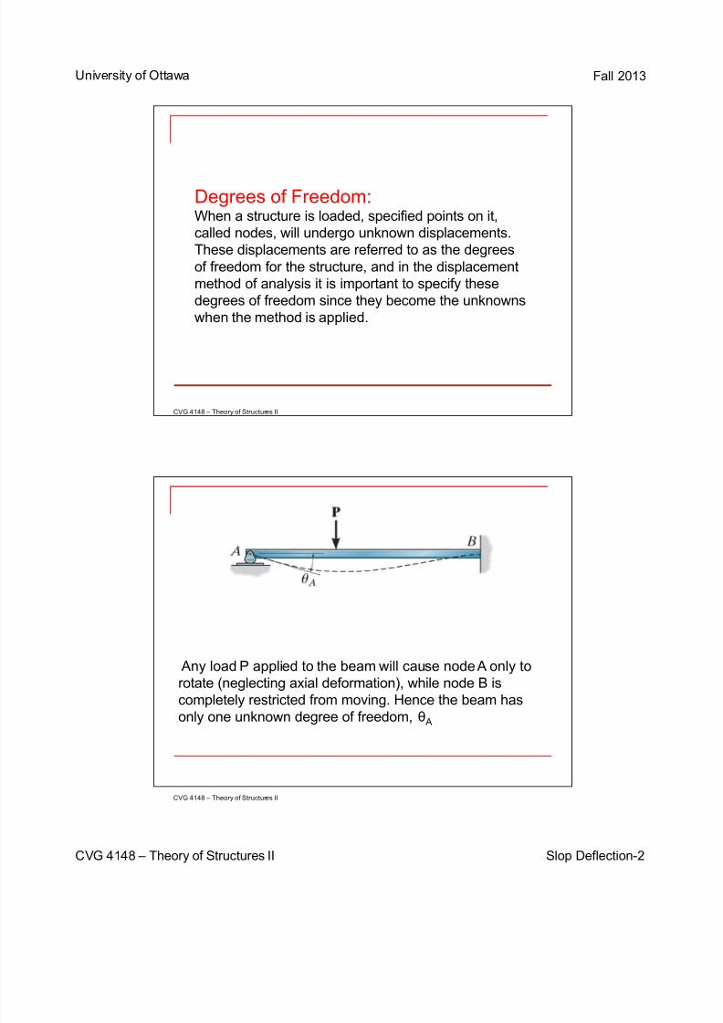
Any load P applied to the beam will cause node A only to
rotate (neglecting axial deformation), while node B is
completely restricted from moving. Hence the beam has
only one unknown degree of freedom, θ A
7/29/2019 Slop Deflection
http://slidepdf.com/reader/full/slop-deflection 3/14
University of Ottawa Fall 2013
CVG 4148 – Theory of Structures II
CVG 4148 – Theory of Structures II
CVG 4148 – Theory of Structures II Slop Deflection - 3
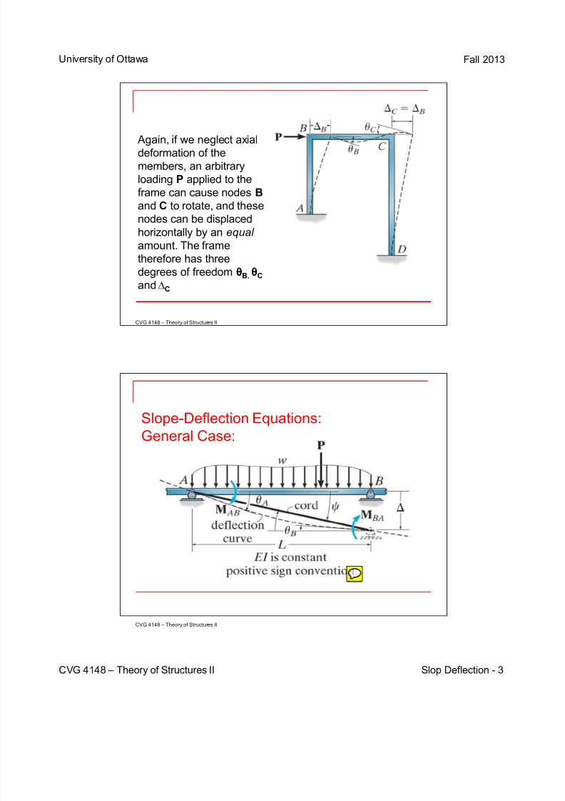
Again, if we neglect axialdeformation of the
members, an arbitrary
loading P applied to the
frame can cause nodes B
and C to rotate, and these
nodes can be displaced
horizontally by an equal
amount. The frame
therefore has three
degrees of freedom θB. θC
and∆C
Slope-Deflection Equations:General Case:
7/29/2019 Slop Deflection
http://slidepdf.com/reader/full/slop-deflection 4/14
University of Ottawa Fall 2013
CVG 4148 – Theory of Structures II
CVG 4148 – Theory of Structures II
CVG 4148 – Theory of Structures II Slop Deflection - 4
In order to develop the general form of the slope-
deflection equations, we will consider the typical span AB
of a continuous beam which is subjected to the arbitraryloading and has a constant EI. We wish to relate the
beam’s internal end moments and in terms of its three
degrees of freedom, namely, its angular displacements θA
and θB and linear displacement ∆ which could be caused
by a relative settlement between the supports.
Moments and angular displacements will be considered
positive when they act clockwise on the span
Furthermore, the linear displacement ∆ is considered
positive as shown, since this displacement causes the
cord of the span and the span’s cord angle to rotateclockwise.
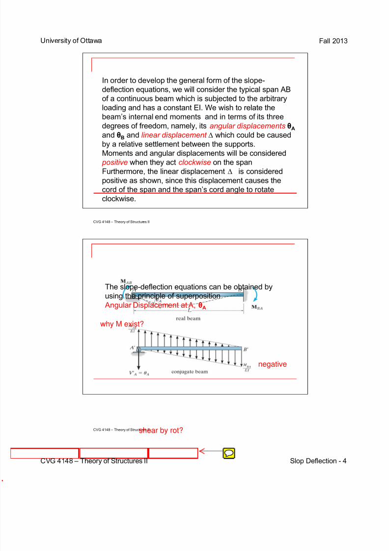
The slope-deflection equations can be obtained byusing the principle of superposition
Angular Displacement at A, θA
negative
why M exist?
shear by rot?
7/29/2019 Slop Deflection
http://slidepdf.com/reader/full/slop-deflection 5/14
University of Ottawa Fall 2013
CVG 4148 – Theory of Structures II
CVG 4148 – Theory of Structures II
CVG 4148 – Theory of Structures II Slop Deflection - 5
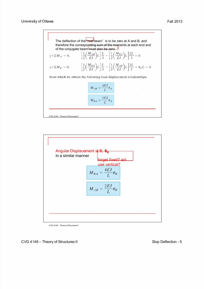
The deflection of the “real beam” is to be zero at A and B, and
therefore the corresponding sum of the moments at each end and
of the conjugate beam must also be zero.
Angular Displacement at B, θB
In a similar manner forget fixed? actuse vertical?
7/29/2019 Slop Deflection
http://slidepdf.com/reader/full/slop-deflection 6/14
University of Ottawa Fall 2013
CVG 4148 – Theory of Structures II
CVG 4148 – Theory of Structures II
CVG 4148 – Theory of Structures II Slop Deflection - 6
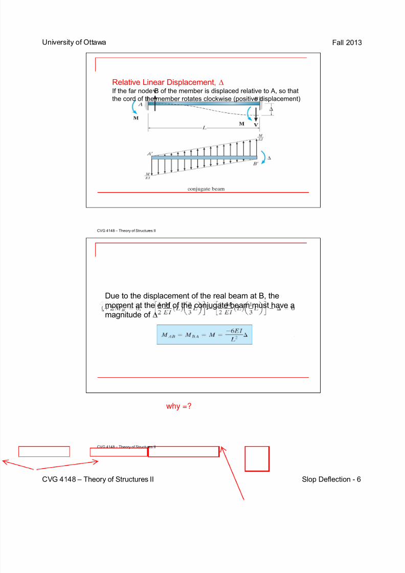
Relative Linear Displacement, ∆If the far node B of the member is displaced relative to A, so that
the cord of the member rotates clockwise (positive displacement)
Due to the displacement of the real beam at B, the
moment at the end of the conjugate beam must have a
magnitude of ∆
why =?
7/29/2019 Slop Deflection
http://slidepdf.com/reader/full/slop-deflection 7/14
University of Ottawa Fall 2013
CVG 4148 – Theory of Structures II
CVG 4148 – Theory of Structures II
CVG 4148 – Theory of Structures II Slop Deflection - 7
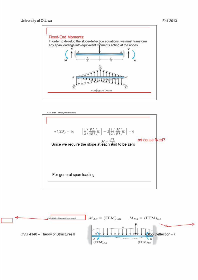
Fixed-End Moments:In order to develop the slope-deflection equations, we must transform
any span loadings into equivalent moments acting at the nodes.
Since we require the slope at each end to be zero
For general span loading
-rot cause fixed?
7/29/2019 Slop Deflection
http://slidepdf.com/reader/full/slop-deflection 8/14
University of Ottawa Fall 2013
CVG 4148 – Theory of Structures II Slop Deflection- 8
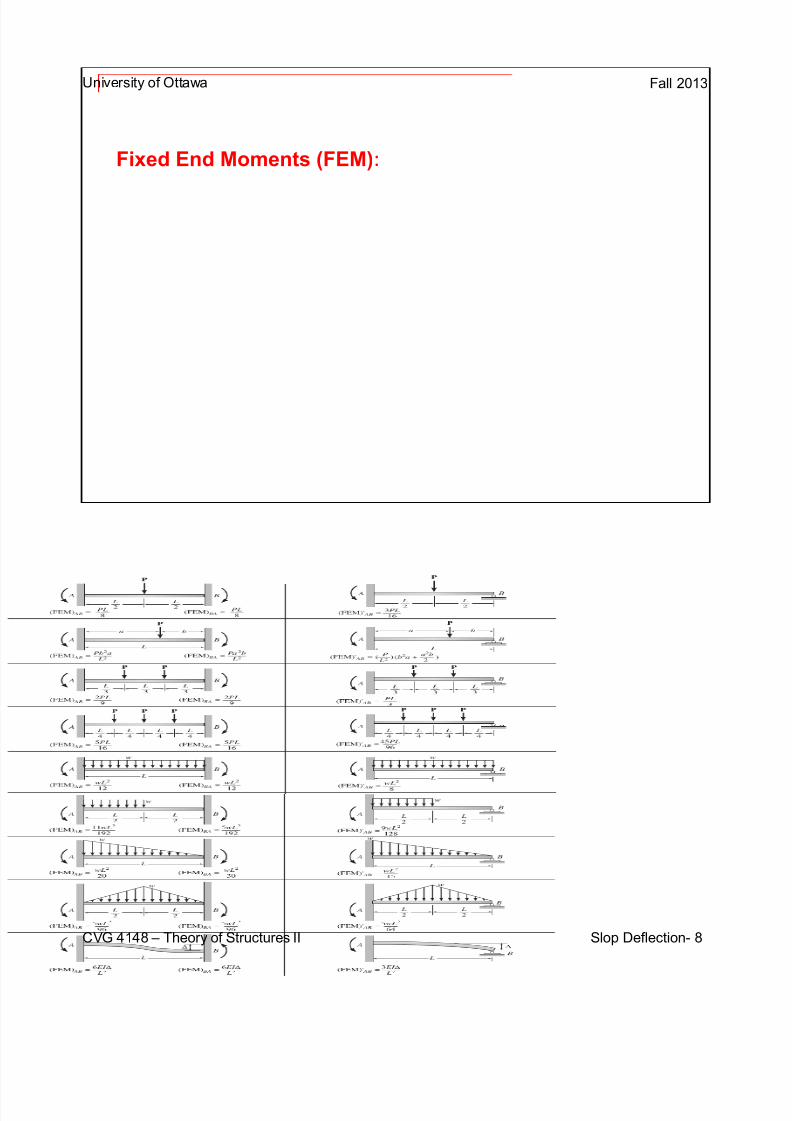
Fixed End Moments (FEM):
7/29/2019 Slop Deflection
http://slidepdf.com/reader/full/slop-deflection 9/14
University of Ottawa Fall 2013
CVG 4148 – Theory of Structures II
CVG 4148 – Theory of Structures II
CVG 4148 – Theory of Structures II Slop Deflection - 9
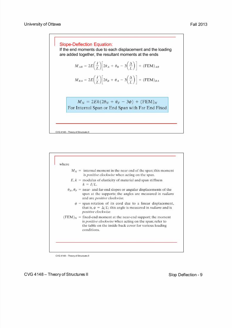
Slope-Deflection Equation:If the end moments due to each displacement and the loading
are added together, the resultant moments at the ends
7/29/2019 Slop Deflection
http://slidepdf.com/reader/full/slop-deflection 10/14
University of Ottawa Fall 2013
CVG 4148 – Theory of Structures II
CVG 4148 – Theory of Structures II
CVG 4148 – Theory of Structures II Slop Deflection - 10
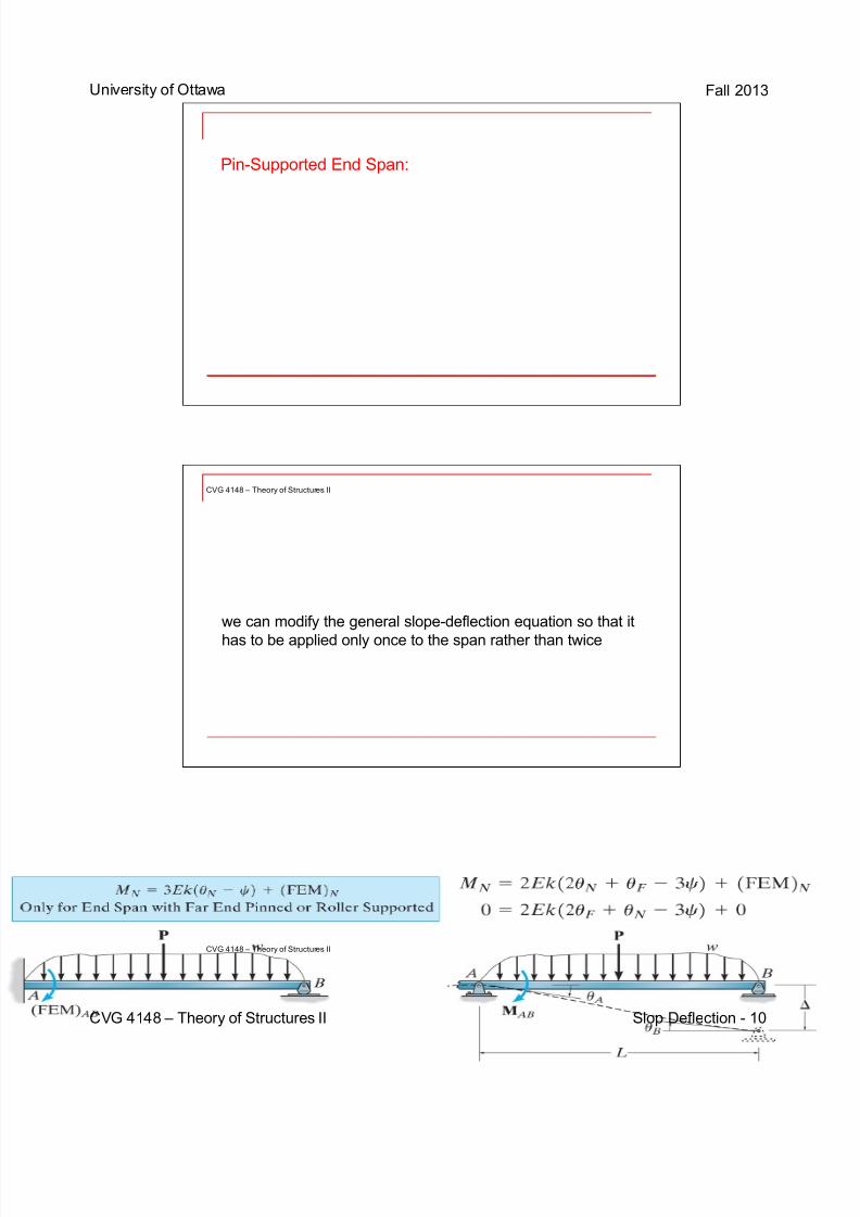
Pin-Supported End Span:
we can modify the general slope-deflection equation so that it
has to be applied only once to the span rather than twice
7/29/2019 Slop Deflection
http://slidepdf.com/reader/full/slop-deflection 11/14
University of Ottawa Fall 2013
CVG 4148 – Theory of Structures II
CVG 4148 – Theory of Structures II
CVG 4148 – Theory of Structures II Slop Deflection - 11
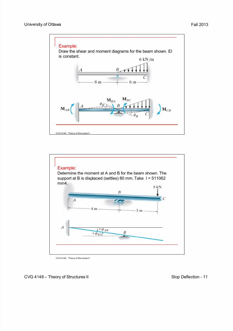
Example:Draw the shear and moment diagrams for the beam shown. EI
is constant.
Example:
Determine the moment at A and B for the beam shown. Thesupport at B is displaced (settles) 80 mm. Take I = 511062
mm4.
7/29/2019 Slop Deflection
http://slidepdf.com/reader/full/slop-deflection 12/14
University of Ottawa Fall 2013
CVG 4148 – Theory of Structures II
CVG 4148 – Theory of Structures II
CVG 4148 – Theory of Structures II Slop Deflection - 12
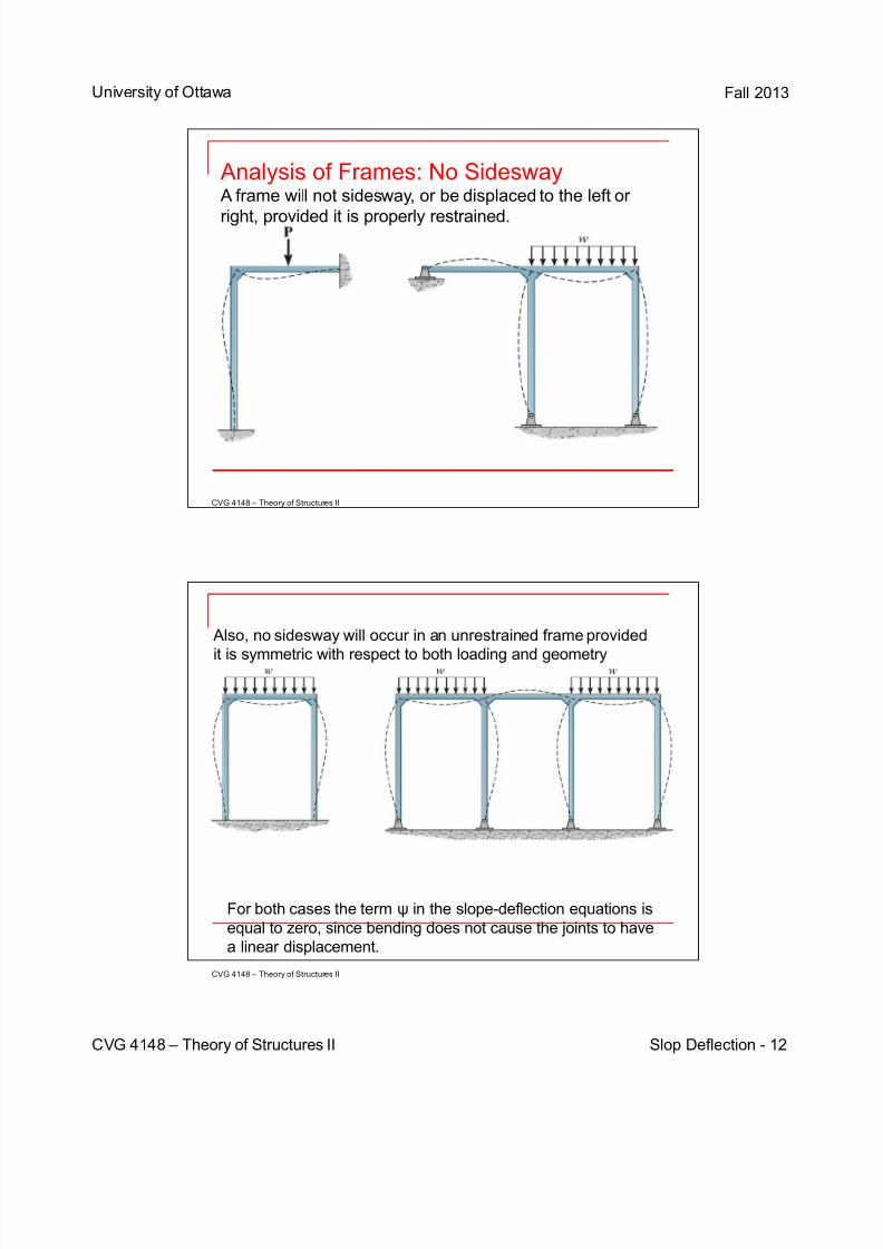
Analysis of Frames: No Sidesway A frame will not sidesway, or be displaced to the left or
right, provided it is properly restrained.
Also, no sidesway will occur in an unrestrained frame provided
it is symmetric with respect to both loading and geometry
For both cases the term ψ in the slope-deflection equations is
equal to zero, since bending does not cause the joints to have
a linear displacement.
7/29/2019 Slop Deflection
http://slidepdf.com/reader/full/slop-deflection 13/14
University of Ottawa Fall 2013
CVG 4148 – Theory of Structures II
CVG 4148 – Theory of Structures II
CVG 4148 – Theory of Structures II Slop Deflection - 13
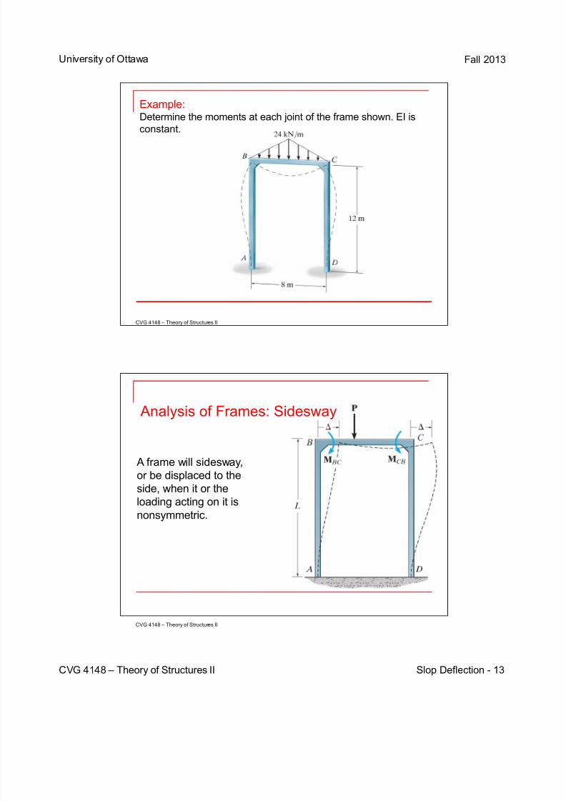
Example:Determine the moments at each joint of the frame shown. EI is
constant.
Analysis of Frames: Sidesway
A frame will sidesway,
or be displaced to the
side, when it or the
loading acting on it is
nonsymmetric.
7/29/2019 Slop Deflection
http://slidepdf.com/reader/full/slop-deflection 14/14
University of Ottawa Fall 2013
CVG 4148 – Theory of Structures II
CVG 4148 – Theory of Structures II
CVG 4148 – Theory of Structures II Slop Deflection - 14
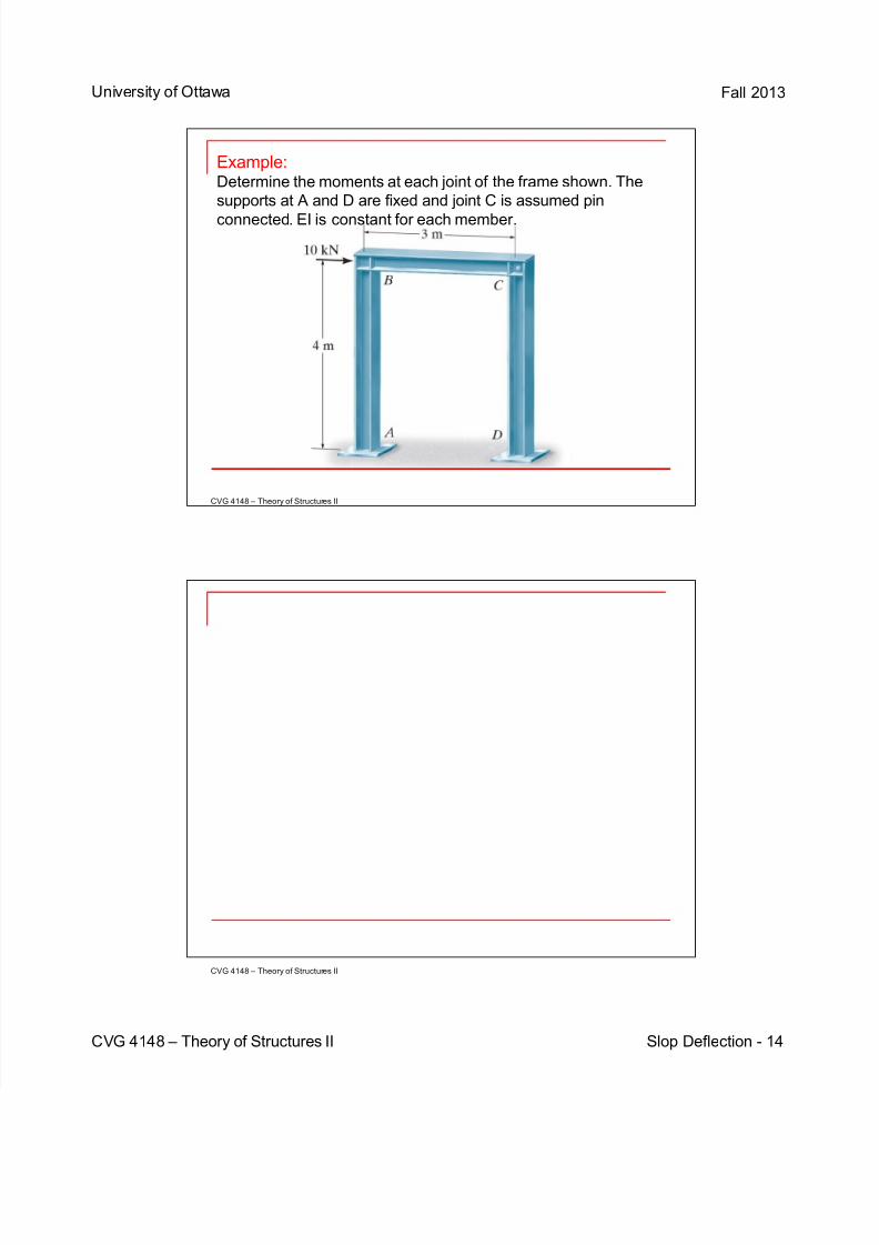
Example:Determine the moments at each joint of the frame shown. The
supports at A and D are fixed and joint C is assumed pin
connected. EI is constant for each member.