Embed Size (px)
Citation preview
Slimes-dam construction in the gold minesof the Anglo American Group
SYNOPSIS
by w. T. RUHMER*. Pr.Eng.. B.Sc. Eng. (Met.) (Fellow)
Current practices generally in accordance with the principles of design and operation of slimes dams within theGold Mining Division of the Anglo American Corporation are described. Although many of the details given areeither obvious or have been amply dealt with elsewhere, these have been included for the sake of completeness.The selection of suitable ground for the deposition of slimes, the initial design and construction of a slimes dam, andits consequent operation are presented in logical sequence. Emphasis is placed on the code of practice for the con-struction of slimes dams issued by the Chamber of Mines of South Africa, and draft regulations (Water Act of 1956)dealing with pollution. Operating costs are included, and possible future trends are discussed.
SAMEVATTING
Die huidige gebruike wat oor die algemeen in ooreenstemming is met die beginsels vir die ontwerp en bedryf vanslykdamme binne die Goudmynafdeling van die Anglo American groep word beskryf. Hoewel bale van die besonder-hede wat verstrek word, voor die hand le, of elders breedvoerig behandel is, word hulle volledigheidshalwe inge-sluit. Die keuse van geskikte grond vir die slykafsetting, die aanvanklike ontwerp en konstruksie van 'n slykdam endie daaropvolgende bedryf daarvan word in 'n logiese volgorde behandel. Daar word klem gele op die gebruikskodevir die konstruksie van slykdamme wat deur die Kamer van Mynwese van Suid-Afrika uitgegee is en die konsep-regulasies (Waterwet van 1956) wat oor besoedeling handel. Die bedryfskoste word ingesluit en moontlike toe-komstige neigings word bespreek.
INTRODUCTION
The design, construction, andoperation of tailings dams in thegold-mining industry has become ofincreasing importance in view of theenormous tonnages requiring de-position. The annual tonnage cur-rently being deposited as a result ofoperations by the Anglo Americangroup of gold mines is calculated atbetween 25 and 26 million, and thetotal area set aside for this purposeapproaches 2200 hectares.
The introduction of more compre-hensive legislation dealing with theprevention of water pollution andthe Chamber Code of Practice fordam construction has resulted in thenecessity for a more scientific ap-proach than has hitherto beenemployed.
From the point of view of stability,it is fortunate that we do not haveto build dams in mountainous areas,which suffer in some instances fromextremes of climate and seismicactivity, nor is it necessary to con-struct such high walls. Thereforethe gold-mining industry has notsuffered the major disasters in-volving heavy loss of life that haveoccurred elsewhere, for example inChile.
On the debit side, however, theeconomics of dam construction are atpresent governed by the labour-
*Consulting Metallurgist, Anglo AmericanCorporation.
intensive methods of wall con-struction currently employed, where-as spigoting or cycloning to pro-duce a coarser sands fraction forwall building is resorted to elsewhere.Attempts to introduce mechanicalmethods of wall construction haveso far met with little success inSouth African gold mining.
The capital costs of the initialconstruction (for example, exca-vation of toe, effluent, and storm-water trenches) are governed by thetopography and the presence of rockrequiring the use of explosives. Themain elements in the establishmentof a new dam are of a civil-en-gineering nature, and, as consider.able variability in capital cost can beexpected, no details of this aspectare given. Costs of civil-engineeringworks, including fencing, trenches,catchment-water dam, piping, andpump station, for a 45 ha dam to bebuilt on gently sloping grounddevoid of rock can be expected tobe in the vicinity of R180 000.
As a number of publications em-bodying the principles of soil mech-anics, hydrology, geology, and topo-graphy are readily available, theemphasis of this paper is on themore practical aspects of residuedisposal.
THE DESIGN OF SLIMESDAMS
In the Anglo American Corpo-ration, the design of a dam is
JOURNAL OF THE SOUTH AFRICAN INSTITUTE OF MINING AND METALLURGY
normally a collaborative effort be-tween the Civil Engineering andMetallurgical Departments, assist-ance being sought from the Mech-anical and Electrical Departmentswhere necessary.
Companies wishing to establishnew slimes dams should consult thefirst three publications in the list ofreferencesl-3 and should adhere asclosely as possible to the principlesthey outline.
Area Required
To determine the area to be setaside for slimes deposition, thefollowing information is required:(1) the monthly rate of deposition in
tons of solids for a period of fiveyears subsequent to the com-mencement of operations; fromthis the initial area required canbe calculated;
(2) a rough estimate of the totaltonnage of ore to be milled overthe life of the mine; from this,the ultimate area can be as-sessed, and, once the maximumpermissible height of the dam isestablished, quantity-surveyingtechniques can be employed todeduce the ultimate storage ca-pacity;
(3) the' possibility of future recla-mation and redeposition foruranium and pyrite recovery;even if ultimate redeposition isin monitored-out areas, the re.
FEI;IRI,IARY 11;174 ~73
IN "11
11 'f
1AREA A-90 HECTARES I
FII"911f
quirements will be considerablyhigher; and
(4) the type of slimes: alkaline gold-plant residue containing pyrite,neutralized uranium-plant resi-due plus neutralized barren solu-tion, or flotation-plant tailingslow in pyrite and at the lowrelative pulp density of 1,3;with neutralized barren solution,the relative density is likely todrop to 1,25 and even less.
The dam requirements for slimesand catchment water can varyaccording to the type of slimes. Forexample, flotation tailings fromwhich pyrite has been recoveredhave the least stability as far as wallbuilding is concerned. Hence, theflattest possible slope-27 ° or evenless-has to be used. The require-ments for catchment water andreturn pumping will also be high.
As a rough guide, an area of 45 hawill allow for the deposition of100 000 tonnes of solids per month,with a monthly rise of approximately10 cm.
The average slimes dam compactsat 0,625 m3 per tonne and contains10 per cent moisture. At 0,625 m3per tonne, the slime would becomesaturated at 20 per cent moisture.For example, a slimes dam 15 mhigh constructed on 85 ha of groundwould contain nearly 18 million tonneof solids at 10 per cent moisture,and a slimes dam 35 m high con-structed on 50 ha would contain25 million tonnes of slime (wall slope30°). Obviously, the ultimate arearequired would not be initially
fenced and trenched but would beemployed for other purposes untilrequired. In addition to the basicarea, an allowance must be made forperimeter services, such as effluentand storm water control, and anadequately sized catchment-waterdam.
Selection of Suitable Ground
The following are the reqUIre-ments for an ideal site:(1) gently sloping ground, with the
slope away from the treatmentplant and towards the area re-served for future extensions,
(2) the absence of wet or marshyground,
(3) the absence of rock, either on thesurface or just below, particu-larly where trenches are likelyto be excavated,
(4) the absence of impermeable sub-surface clay strata,
(5) remoteness from inhabited areas,and
(6) remoteness from main roads,power lines, rivers, and streams.
As it is probably impossible tomeet all the requirements, thefollowing precautions should betaken to prevent future trouble.(a) Small-scale topographic maps
of the area (scale 1 :50 000,30 m contours) and any avail-able aerial photographs shouldbe studied.
(b) The most promising sites shouldbe inspected on the ground.
(c) After the most suitable site hasbeen selected, the areas onwhich wall construction is likely
~~'
EXIS2:'.-NGd-=-""=-- - --- -
--,P"O~N~,=-- R~~ -'-' ~~6"--- .'~ ---: - - - --A
" ' i"76/- F"
-
,\1';-2' ':\. To'"
TRE~B6 --25\-'------
INNER WALL 'TRENCH
'To RETURN _TER CAM
",T"RSECl'ION""
TOE TRENCHES
Fig. I-An ide~1 ,limes-dam layout on gently sloping ground
~OI)RNAL OF TH(: SOUTH AFRICAN INSTITUTE OF MINING AND METALLURGY~74 FEBRUARY 1974
to take place should be in-vestigated by the sinking oftest pits and trenches so thatthe nature of the shallow sub-surface soils can be determined.
(d) If possible, larger-scale maps(1 :2500 with 1,5 m contours, orpreferably 1 :500 with 1 mcontours) should be employedfor the detailed design of theslimes and catchment-waterdams.
(e) Run-off should be estimatedfrom precipitation records sothat diversion stormwatertrenches and catchment-waterdams can be adequately de-signed.
General Layout
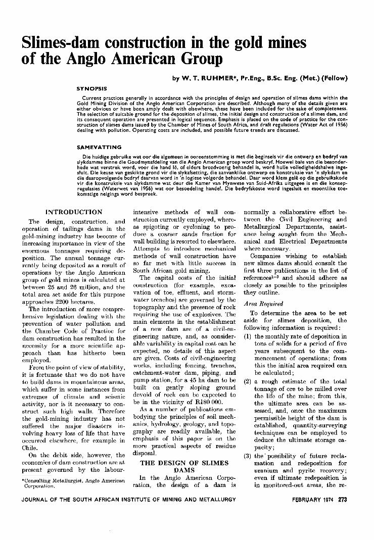
The layout should take advantageof the contours so that the flow ofeffluent and storm water is facilitated,and the necessity for building morethan one catchment-water dam withits attendant return-pumping facili-ties should be avoided. Althoughdams should preferably be squarein shape to provide the maximumcapacity and to avoid unnecessarycorners, this is rarely possible. Acuteangles should be avoided in thelaying out of the periphery, sincedifferential lateral pressures developand may cause cracks to form. Fig. 1shows an almost ideal site.
Fencing and Trenching
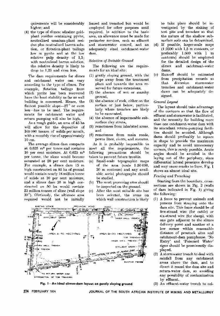
Starting from the boundary, cross-sections are shown in Fig. 2 (wallsof dam indicated in Fig. 1) givingthe following:(1) A fence to prevent animals and
persons from straying onto thedam site. This fence should be offive-strand wire (for cattle) orsix-strand wire (for sheep), withone gate adjacent to the slimesdelivery point and another at alow corner within reasonabledistance of penstock sites andcatchment-dam pumphouse. 'NoEntry' and 'Poisoned Water'signs should be prominently dis-played.
(2) A stormwater trench to deal withrainfall from any catchmentareas above the dam, and todivert it round the dam site andreturn-water dam, so avoidingany possibility of contaminationby effluent.
(3) An effluent-water trench to col-
I~~iIi~..
%!~~
"'A-,i~LI;j;jO X_,._.1,__\..610
-2.7,,"~- __1'5240.- _..18288_-SECTION B-B
'M..
0.0~
'EI'CE
-r~"'0--0~- --
~I r~,~
~
10 l-j ~,io ~ Z Z ~~~:O" ~" ~.. Z,...
0' H'
~ Io; glo z;:.
I~...
c'~~IO"'"'
Q "IQ t-, ~ ':',7F~ i"',~/~/,- ~_>-i -~
___Q2Q6Q... ~d,-'220 '_;-'220 ;(..,:,..-' _.,--,,~ql4...q,~;3Q
-. 12"2
:- '~.2"o... -1 le ?een~'
"-SEC~N E-E--,..,.- -
Fig. 2- Typical trenching cross-sections
lect penstock and wall run-offwater and to lead it to thecatchment water or return dam.
(4) Paddy dams or slimes-entrain-ment paddocks to contain solidscarried down by wall run-offwater.
(5) A toe trench for the establish-ment of the outside face of theouter wall, otherwise known asNo. 1 wall trench.
(u) A trench for the establishment ofthe inside face of the outer wall,otherwise known as No. 2 walltrench.
At a later stage, a third embank-ment is built inside the dam tocreate the inside face of the innerwall.
Fig. 2 indicates clearly the natureof the excavations required for theestablishment of a dam. Five cross-sections (four main and one centredividing wall) are shown. Trenchdistance will vary somewhat, de-pending on the slope of the ground.On the upstream side of steeplysloping ground, distances should bereduced to prevent accumulations ofwater against the toe of the wall.
Paddy dams are developed by theerection of transverse walls at inter-vals between the toe and effluent-water trenches, the purpose being tocontain some of the solids washeddown from the walls during heavyrain or storms.
French Drains
Wherever walls have to be builton marshy, rocky, or other areaswith poor drainage characteristics,
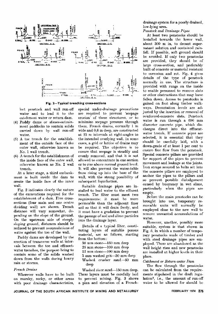
special under-drainage precautionsare required to prevent 'seepageerosion' of these structures, or tominimize seepage pressure throughthem. French drains, normally 1 mwide and 0,6 m deep, are constructedat 15 m intervals at right-angles tothe intended overlying wall. In somecases, a grid or lattice of drains maybe required. The objective is toensure that seepage is steadily andevenly removed, and that it is notallowed to concentrate in one sectionor to rise above normal ground level.It will also prevent the water-tablefrom rising up into the base of thewall, with the strong possibility ofsubsequent liquefaction.
Suitable drainage pipes are in-stalled to lead water to the effluenttrench. The filter must meet tworequirements: it must be morepermeable than the adjacent finersoil so that it will drain freely, andit must have a gradation to preventthe passage of soil and slime particlesinto the drainage layer.
Details of a typical filter, consti-tuting layers of suitable porousmaterial, are as follows, startingfrom the bottom:
50 mm stone-150 mm deep25 mm stone-WO mm deep12 mm stone-WO mm deep3 mm washed grit-50 mm deepWashed crusher sand-50 mm
deep
Washed river sand-150 mm deep.These layers must be carefully laidto prevent mixing. Fig. 3 showsa plan and elevation of a French-
JOURNAL OF THE SOUTH AFRICAN INSTITUTE OF MINING AND METALLURGY
drainage system for a poorly drained,low-lying area.Penstock and Drainage Pipes
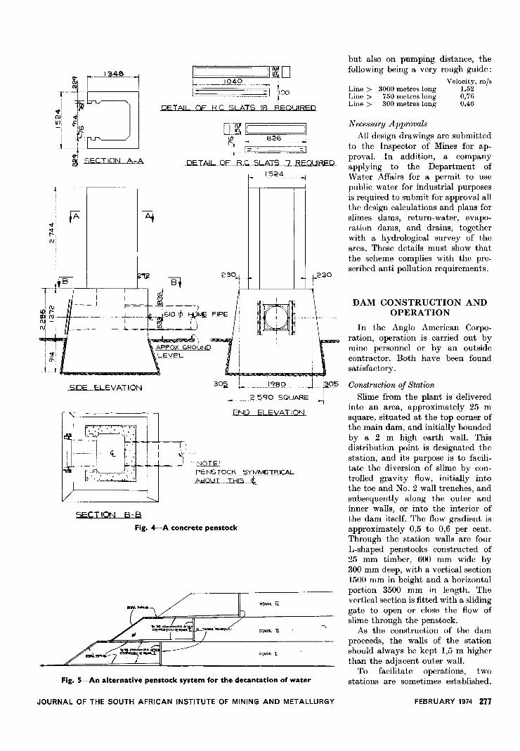
At least two penstocks should beinstalled towards the lower wall,about 300 m in, to decant super-natant solution and contained rain-fall. If possible, soft ground shouldbe avoided. If only two penstocksare provided, they should be oflarge cross-section, and preferablybuilt of concrete or material resistantto corrosion and rot. Fig. 4 givesdetails of the type of penstocknormally in use. The structure isprovided with rungs on the insideto enable personnel to remove slatsor other obstructions that may havefallen down. Access to penstocks isgained on foot along timber walk-ways. Decantation levels are ad-justed by the insertion or removal ofreinforced-concrete slats. Penstockwater is run through a 600 mmdiameter concrete pipe, which dis-charges direct into the effluent-water trench. If concrete pipes areselected, it is essential that theyshould be carefully laid, with adown-grade of at least 1 per cent toensure free flow from the penstock.Special concrete pillars are providedfor support of the pipes to preventmovement and leakage at the joints.Iron straps secured to bolts set intothe concrete pillars are employed toanchor the pipes to the pillars a:p.dso prevent possible dislodgementcaused by buoyancy in wet slime,particularly when the pipes areempty.
Before the main penstocks can bebrought into use, temporary re-movable units will normally beemployed close to the new wall toremove unwanted accumulations ofwater.
However, another, possibly moresuitable, system is that shown inFig. 5, in which a number of tempo-rary penstocks made of timber andwith steel drainage pipes are em-ployed. These are abandoned as thewall height rises and new penstocksare installed at higher levels in theirplace.
Catchment or Return-water DamThe flow through the penstocks
can be calculated from the require-ments stipulated in the draft regu-lation3, i.e., the amount of run-offwater to be allowed for should be
FEBRUARY 1974 275
---A ~-- :::-- --
,---/'
~I~~:/
~
J~: /~/~~//' 8 /'/ ~f.
/' Jm¥~- --;j,/ 1 ---
TQ&; TRE
RENCI-f
EF~L(JeNiDRAIN
/-~ ii)
(I)
--% %\
0 0
\6~Y
/'
~ft'9
t;30~O,~ \o?#-
'\1\/z
BACKF"ILL WITH 150 THK LAYERFXCAVATED MATERIAl
(DO NOT COL4PM'-T)
t\ START TRENCH
-,. ~. ;.;~I-- 30000 N.~ .15
E'Nr:A<:;1= IN ('J)NC:RFTE3000 ~ 450X ASO
TYPICAL LONG
~~ --L! I'. . ... ui, 2c~ ~2'5
.,',." ..'.. 01- CONCRETE, , f\J;~~~-
U
..
- jJ EHCA<CMCNT~ r ~~ L iooo_~ WASTE ROCK
1f"t
~tTYPICAL CROSS SECTION OF SECTION UNDER TOESEEPAGE DRAINS TREI'r.HSCAL!;; 1:25 SCALE 1:25
Fig. 3-Details of a typical French-drainage system
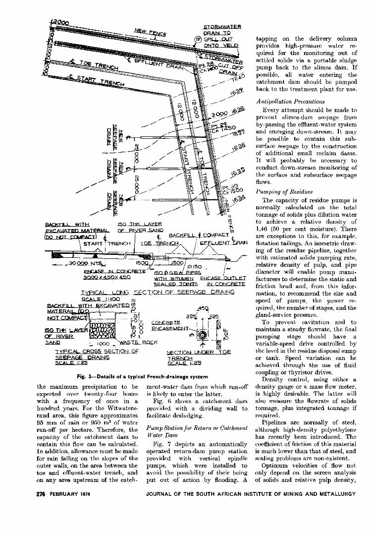
the maximum precipitation to beexpected over twenty-four hourswith a frequency of once in ahundred years. For the Witwaters-rand area, this figure approximates95 mm of rain or 950 m3 of waterrun-off per hectare. Therefore, thecapacity of the catchment dam tocontain this flow can be calculated.In addition, allowance must be madefor rain falling on the slopes of theouter walls, on the area between thetoe and effluent-water trench, andon any area upstream of the catch.
276 FEBRUARY 1974
ment-water dam from which run-offis likely to enter the latter.
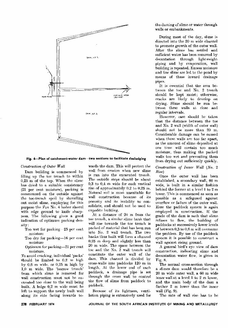
Fig. 6 shows a catchment damprovided with a dividing wall tofacilitate desludging.
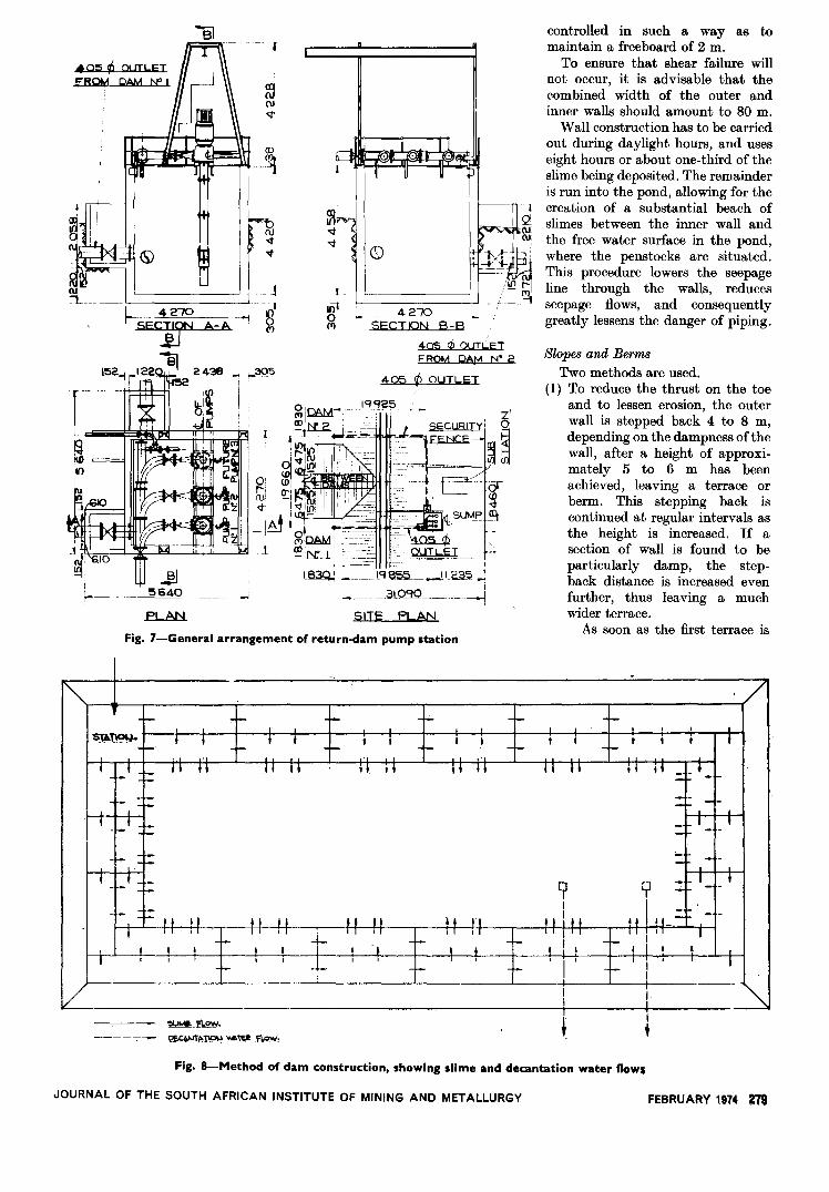
Pump Station for Return or CatchmentWater Dam
Fig. 7 depicts an automaticallyoperated return-dam pump stationprovided with vertical spindlepumps, which were installed toavoid the possibility of their beingput out of action by flooding. A
tapping on the delivery columnprovides high-pressure water re-quired for the monitoring out ofsettled solids via a portable sludgepump back to the slimes dam. Ifpossible, all water entering thecatchment dam should be pumpedback to the treatment plant for use.
A ntipollution Precautions
Every attempt should be made toprevent slimes-dam seepage fromby-passing the effluent-water systemand emerging down-stream. It maybe possible to contain this sub-surface seepage by the constructionof additional small reclaim dams.It will probably be necessary toconduct down-stream monitoring ofthe surface and subsurface seepageflows.
Pumping of Residues
The capacity of residue pumps isnormally calculated on the totaltonnage of solids plus dilution waterto achieve a relative density of1,46 (50 per cent moisture). Thereare exceptions to this, for example,flotation tailings. An isometric draw-ing of the residue pipeline, togetherwith estimated solids pumping rate,relative density of pulp, and pipediameter will enable pump manu-facturers to determine the static andfriction head and, from this infor-mation, to recommend the size andspeed of pumps, the power re-quired, the number of stages, and thegland-service pressure.
To prevent cavitation and tomaintain a steady flowrate, the finalpumping stage should have avariable-speed drive controlled bythe level in the residue disposal sumpor tank. Speed variation can beachieved through the use of fluidcoupling or thyristor drives.
Density control, using either adensity gauge or a mass flow meter,is highly desirable. The latter willalso measure the flowrate of solidstonnage, plus integrated tonnage ifrequired.
Pipelines are normally of steel,although high-density polyethylenehas recently been introduced. Thecoefficient of friction of this materialis much lower than that of steel, andscaling problems are non-existent.
Optimum velocities of flow notonly depend on the screen analysisof solids and relative pulp density,
JOURNAL OF THE SOUTH AFRICAN INSTITUTE OF MINING AND METALLURGY
r1346
1r""
}~
~
"
~:(\)1 <tIlJj fl
-I 1,in__j-
m ~ECT ION A-A
.----------
iifA
~i1",rui
i
!
I
T-~~! !
~ ~lex!(T)
'--~ -Iru' II -i -
Ire
- - L-----I-- - --b.~
SIDE ELEVATION
[M',
I ~-J ~':: --. '..' . '-.,
SECT ION
D~I:<D,... 6261"-1-1
t -
DETAIL OF Rc. SLATS 7 REOUI~ED
I:
Lj
:110un_.l94()
- : jI '.100
TDETAIL OF RC SLATS lA REQUIRED
Fig. 5-An alternative penstock system for the decantation of water
f- -
1524
i
A+
230, ...,
w
-I
j-230
L nml~aoJ ~. 0.5
25ew SQLJ,6,RE_-i
END ELEVATION
305Pf
:~-l)-J~I'JOTE\
PENSTOCK SYMMETRCAL.AbQUT_II:::I15-t
B-B
Fig. 4-A concrete penstock
51""E1;[
51">1.n
o"G' 1
JOURNAL OF THE SOUTH AFRICAN INSTITUTE OF MINING AND METALLURGY
but also on pumping distance, thefollowing being a very rough guide:
Velocity, m/s1,520,760,46
Line> 3000 metres longLine> 750 metres longLine> 300 metres long
Necessary Approvals
All design drawings are submittedto the Inspector of Mines for ap-proval. In addition, a companyapplying to the Department ofWater Affairs for a permit to usepublic water for industrial purposesis required to submit for approval allthe design calculations and plans forslimes dams, return-water, evapo-ration dams, and drains, togetherwith a hydrological survey of thearea. These details must show thatthe scheme complies with the pre-scribed anti pollution requirements.
DAM CONSTRUCTION ANDOPERATION
~,
In the Anglo American Corpo-ration, operation is carried out bymine personnel or by an outsidecontractor. Both have been foundsatisfactory.
Construction of Station
Slime from the plant is deliveredinto an area, approximately 25 msquare, situated at the top corner ofthe main dam, and initially boundedby a 2 m high earth wall. Thisdistribution point is designated thestation, and its purpose is to facili-tate the diversion of slime by con-trolled gravity flow, initially intothe toe and No. 2 wall trenches, andsubsequently along the outer andinner walls, or into the interior ofthe dam itself. The flow gradient isapproximately 0,5 to 0,6 per cent.Through the station walls are fourL-shaped penstocks constructed of25 mm timber, 600 mm wide by300 mm deep, with a vertical section1500 mm in height and a horizontalportion 3500 mm in length. Thevertical section is fitted with a slidinggate to open or close the flow ofslime through the penstock.
As the construction of the damproceeds, the walls of the stationshould always be kept 1,5 m higherthan the adjacent outer wall.
To facilitate operations, twostations are sometimes established.
FEBRUARY 1974 277
~~
PU"P ~u""
O", \-,0 ~\.
/>EffLU"'" ~,~"0."".'"
D'" ", 2.
Fig. 6-Plan of catchment-water dam-two sections to facilitate desludging
Construction of Outer Wall
Dam building is commenced byfilling up the toe trench to within0,25 m of the top. When the slimehas dried to a suitable consistency(21 per cent moisture), packing iscommenced on the outside againstthe toe-trench spoil by shovellingout moist slime, employing for thispurpose the Fox No. 4 lasher shovelwith edge ground to knife sharp-ness. The following gives a goodindication of optimum packing den-sity:
Too wet for packing-25 per centmoisture
Too dry for packing-16 per centmoisture
Optimum for packing-21 per centmoisture.
To avoid cracking, individual 'packs'should be limited to 0,2 m highby 0,6 m wide, or 0,25 m high by1,0 m wide. The 'borrow trench'from which slime is removed forwall construction must not be ex-cavated too close to the wall beingbuilt. A ledge 0,2 m wide must beleft to support the newly built wallalong its side facing inwards to-
278 FEBRUARY 1974
wards the dam. This will protect thewall from erosion when new slimeis run into the excavated trench.The outside steps should be about0,3 to 0,4 m wide for each verticalrise of approximately 0,2 to 0,25 m.Natural soil is most unsuitable forwall construction because of itsporosity and its inability to con-solidate, and should not be used toexpedite building.
At a distance of 20 m from thetoe trench, a similar slime bank thatwill rise towards the toe trench ispacked of material that has been runinto No. 2 wall trench. The twobanks thus built will form a channel0,25 m deep and slightly less than20 m wide. The space between thetoe and the No. 2 wall trench willconstitute the outer wall of thedam. This channel is divided bycross-walls into paddocks 120 m inlength. At the lower end of eachpaddock, a drainage pipe is setthrough the cross wall to controlthe flow of slime from paddock topaddock.
Because of its lightness, venti-lation piping is extensively used for
the ducting of slime Of water throughwalls or embankments.
During most of the day, slime isdirected into the 20 m wide channelto promote growth of the outer wall.After the slime has settled andsufficient water has been removed bydecantation through lightweightpiping and by evaporation, wallbuilding is repeated. Excess moistureand fine slime are led to the pond bymeans of these inward drainagepipes.
It is essential that the area be-tween the toe and No. 2 trenchshould be kept moist; otherwise,cracks are likely to develop ondrying. Slime should be run be-tween these walls at close andregular intervals.
However, care should be takenthat the distance between the toeand No. 2 wall (width of outer wall)should not be more than 20 m.Considerable damage can be causedwhen these walls are too far apart,as the amount of slime deposited atone time will contain too muchmoisture, thus making the packedwalls too wet and preventing themfrom drying out sufficiently quickly.
Construction of Inner Wall (No. 2Rise)
Once the outer wall has beenestablished, a secondary wall, 60 mwide, is built in a similar fashionbehind the former at a level 1 to 2 mlower. This is commenced as soon aspossible as a safeguard againstoverflow or failure of the outer wall.Here the paddock system is againemployed in construction. If thegrade of the dam is such that slimerefuses to flow, the building ofpaddocks at successively lower levelsof between 0,3 to 0,6 m will overcomethe problem. By use of the paddocksystem it is possible to construct awall against rising ground.
A general bird's eye view of damconstruction, indicating slime anddecantation water flow, is given inFig. 8.
The normal cross-section througha slimes dam would therefore be a20 m wide outer wall, a 60 m wideinner wall at a level 1 to 2 m lower,and the main body of the dam afurther 2 m lower than the innerwall (Fig. 9).
The rate of wall rise has to be
JOURNAL OF THE SOUTH AFRICAN INSTITUTE OF MINING AND METALLURGY
B1
~O5 ~ 01 JTLI;:T
~ROM DAM N" I
~ 4270--1
~:B1
l~ rl~ ~4~ ~ f-395
~-
--10
~~
'5640
~
-
f
~~
(DI
.n~
I(\J:<t~
'<t, <D
J
8'('),
I.
Ii)t0(Y)
4 <;70SECTION B-B
405 di OUTLETFROM DAf'-1N' 2
405 ~ OUTLET
LB3Q.: 1----
SITE PLAN
Fig. 7-General arrangement of return-dam pump station
~..xl2w.
~ ~~. 1P. f~
controlled in such a way as tomaintain a freeboard of 2 m.
To ensure that shear failure willnot occur, it is advisable that thecombined width of the outer andinner walls should amount to 80 m.
Wall construction has to be carriedout during daylight hours, and useseight hours or about one-third of theslime being deposited. The remainderis run into the pond, allowing for thecreation of a substantial beach ofslimes between the inner wall andthe free water surface in the pond,where the penstocks are situated.This procedure lowers the seepageline through the walls, reducesseepage flows, and consequentlygreatly lessens the danger of piping.
Slopes and Berms
Two methods are used.(1) To reduce the thrust on the toe
and to lessen erosion, the outerwall is stepped back 4 to 8 m,depending on the dampness of thewall, after a height of approxi-mately 5 to 6 m has beenachieved, leaving a terrace orberm. This stepping back iscontinued at regular intervals asthe height is increased. If asection of wall is found to beparticularly damp, the step-back distance is increased evenfurther, thus leaving a muchwider terrace.
As soon as the first terrace is
. I
III
t.
III+
Fig. 8-Method of dam construction, showing slime and decantation water flows
JOURNAL OF THE SOUTH AFRICAN INSTITUTE OF MINING AND METALLURGY FEBRUARY 1974 279
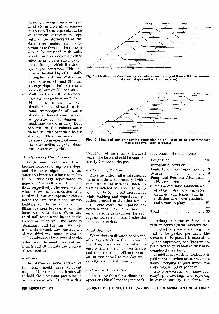
formed, drainage pipes are putin at 350 m intervals to removerainwater. These pipes should beof sufficient diameter to copewith all the stormwater as thedam rises higher and moreterraces are formed. The terracesshould be provided with wallsabout 1 m high along their outeredge to provide a small catch-ment through which the drain-age pipes penetrate. This im-proves the stability of the wallsduring heavy storms. Wall slopesvary between 31 ° and 36°, theaverage slope including terracesvarying between 23 ° and 30 °.
(2) Walls are built without terraces,varying in slope between 27 ° and36°. The toe of the outer wallshould not be allowed to be-come water-logged; all watershould be drained away as soonas possible by the digging ofsmall furrows 0,6 m away fromthe toe to the effluent-watertrench in order to form a betterdrainage. These furrows shouldbe about 10 m apart. Obviously,the construction of paddy damswill be affected by this.
Maintenance of Wall thickness
As the outer wall rises, it willbecome narrower owing to its slope,and the inner edges of both theouter and inner walls have thereforeto be periodically repositioned tomaintain the widths of 20 m and60 m respectively. The outer wall iswidened by the construction of athird wall at an appropriate distanceinside the dam. This is done by thebuilding of the usual bank andfilling the area between it and theinner wall with slime. When thisthird wall reaches the height of thesecond or inner wall, the latter isabandoned and the third wall be-comes the second. The constructionof the third wall must be startedwell in advance of the time that theouter wall becomes too narrow.Figs. 9 and 10 indicate the progressof construction.
Freeboard
The slime-containing surface ofthe dam should have sufficientheight of inner wall (i.e., freeboard)to hold the maximum precipitationto be expected over 24 hours with a
280 FEBRUARY 1974
-t- JII
~~--~ -
Fig. 9-ldealized section showing stepwise repositioning of 11and III to accommo-date wall slope (wall without terraces)
~'-_t.
""T"~
'A'
Fig. ID-Idealized section showing repositioning of 11 and III to accommodatewall slope (wall with terraces)
frequency of once in a hundredyears. The height should be approxi-mately 2 m above the pool.
Subdivision of the Dam
After the outer wall is established,the area ofthe dam is usually dividedinto two equal sections. Each inturn is isolated for about three tofour months to dry out thoroughly,while building and deposition ope-rations proceed on the other section.
In some cases, the separate de-position of tailings high in uraniumon an existing dam surface, for su b-sequent reclamation, complicates thebuilding operation.
Night Operation
When slime is diverted at the endof a day's shift to the interior ofthe dam, care must be taken toensure that the change-over is safeand that the slime will not returnon its own accord to the day wall,causing considerable damage.
Packing and Other Labour
The labour force for a slimes-damoperation (260 000 tonnes per month)
may consist of the following:
Designation
European Supervisor. . . . .Bantu Production Supervisors.Guards ,....Pump and Penstock Attendants
(12-hour shifts)"""
2Slime Packers (also maintenance
of effluent drains, stormwatertrenches, and fences, and in-stallation of wooden penstocksand terrace piping) 21
No.
136
Total . . . . . . . . . . . 33
Packing is normally done on atask or bonus system, whp,reby eachindividual is given a set length ofwall to be packed per shift. Thedistance to be packed is marked offby the Supervisor, and Packers arepermitted to go as soon as they havecompleted their task.
If additional work is needed, it ispaid for at overtime rates. On slimesdams belonging to gold mines, thedaily task is 150 m per man.
Any pipework such as dismantling,relaying, extending, and repairingis carried out by the slimes-dam
JOURNAl... OF THE SOUTH AFRICAN INSTITUTE OF MINING AND METALLURGY
gang. Pumps, valves, motors, andswitchgear are overhauled on thebasis of scheduled maintenance.
Equipment
The following is a typical list ofthe equipment required for theoperation of a large dam:33 boiler or utility suits (one issued
to each person)33 jerseys (one issued to each person
in winter)33 oilskin suits (one issued to each
person)33 pairs of gumboots (one issued to
each person)1 first-aid kit1 snakebite kit
40 shovels-No. 4 Lasher6 picks4 spare pick handles1 bicycle2 wheel barrows1 ventilation-pipe cutter2 rolls of mason's line1 30 m tape1 fire-extinguisher2 4 lb hammers1 set of spanners2 fencing pliers1 wire puller2 soft brooms6 sickles1 electric grinder for sharpening
tools1 set of cold chisels
plastic food containers.
Water Reclamation and Prevention ofPollution
Supernatant water (comprising thesolution accompanying depositedresidues and rain water) accumulat-ing within the dam is contained bythe penstocks and decanted throughthem via the effluent-water trench tothe catchment dam, whence it isdelivered via pumps to the treatmentplant. As mentioned previously, theamount of rain water to be allowedfor should be the maximum pre-cipitation to be expected over 24hours with a frequency of once ina hundred years.
During rainy weather, thequantity of water accumulatingaround the penstocks may exceedthe amount that can be immediatelyaccepted in the treatment plant. Inthis event, the water may be re-tained on the dam but should beremoved as soon as possible, par-ticularly if the stability of the walls
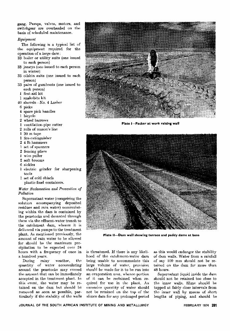
Plate I-Packer at work raising wall
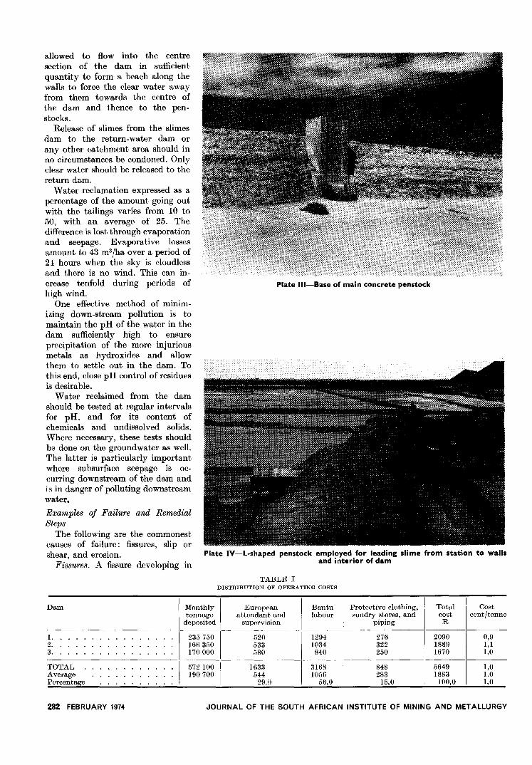
Plate "-Dam wall showing terrace and paddy dams at base
is threatened. If there is any likeli-hood of the catchment-water dambeing unable to accommodate thislarge volume of water, provisionshould be made for it to be run intoan evaporation area, whence portionof it can be reclaimed when re-quired for use in the plant. Anexcessive quantity of water shouldnot be retained on the top of theslimes dam for any prolonged period
as this would endanger the stabilityof dam walls. Water from a rainfallof say 100 mm should not be re-tained on the dam for more than48 hours.
Supernatant liquid inside the damshould not be retained too close tothe inner walls. Slime should betapped at fairly close intervals fromthe inner wall by means of shortlengths of piping, and should be
JOURNAL OF THE SOUTH AFRICAN INSTITUTE OF MINING AND METALLURGY FEBRUARY 1974 281
Dam Monthly Europeantonnage attendant and
deposited supervision
1. 235750
I
5202. 166350 5333. 170 000 580
TOTAL
I
572 lOO
I
1633Average 190 700 544Percentage 29,0
Bantu Protective clothing, Total Costlabour sundry stores, and cost cent/tonne
piping R
1294 276 2090 0,91034 322 1889 I, I
840 250 1670 1,0-----
3168 848 5649 1,01056 283 1883 1,0
56,0 15,0 100,0 1,0
allowed to flow into the centresection of the dam in sufficientquantity to form a beach along thewalls to force the clear water awayfrom them towards the centre ofthe dam and thence to the pen-stocks.
Release of slimes from the slimesdam to the return-water dam orany other catchment area should inno circumstances be condoned. Onlyclear water should be released to thereturn dam.
Water reclamation expressed as apercentage of the amount going outwith the tailings varies from 10 to50, with an average of 25. Thedifference is lost through evaporationand seepage. Evaporative lossesamount to 43 m3fha over a period of21 hours when the sky is cloudlessand there is no wind. This can in-crease tenfold during periods ofhigh wind.
One effective method of minim-izing down-stream pollution is tomaintain the pH of the water in thedam sufficiently high to ensureprecipitation of the more injuriousmetals as hydroxides and allowthem to settle out in the dam. Tothis end, close pH control of residuesis desirable.
Water reclaimed from the damshould be tested at regular intervalsfor pH, and for its content ofchemicals and undissolved solids.Where necessary, these tests shouldbe done on the groundwater as well.The latter is particularly importantwhere subsurface seepage is oc-curring downstream of the dam andis in danger of polluting downstreamwater..
Examples of Failure and RemedialSteps
The following are the commonestcauses of failure: fissures, slip orshear, and erosion.
Fissures. A fissure developing in
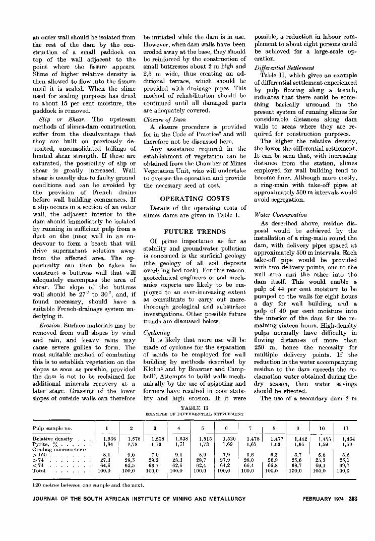
Plate Ill-Base of main concrete penstock
Plate IV-L-shaped penstock employed for leading slime from station to wallsand interior of dam
TABLE IDISTRIBUTION OF OPERATING COSTS
282 FEBRUARY 1974 JOURNAL OF THE SOUTH AFRICAN INSTITUTE OF MINING AND METALLURGY
Pulp sample no. 1 2 3 4 5 6 7 8 9 10 11
Relative density 1,558 1,576 1,558 1,538 1,515 1,520 1,476 1,477 1,442 1,455 1,464Pyrite, % . . . 1,84 1,78 1,73 1,71 1,73 1,69 1,67 1,63 1,65 1,59 1,59Grading micrometers:> 150 8,1 9,0 7,0 9,1 8,9 7,9 5,6 6,3 5,7 5,6 5,2>74 27,3 28,5 29,3 28,3 28,7 27,9 28,0 26,9 25,6 25,3 25,1< 74 64,6 62,5 63,7 62,6 62,4 64,2 66,4 66,8 68,7 69,1 69,7Total 100,0 100,0 100,0 100,0 100,0 100,0 100,0 100,0 100,0 100,0 100,0
an outer wall should be isolated fromthe rest of the dam by the con-struction of a small paddock ontop of the wall adjacent to thepoint where the fissure appears.Slime of higher relative density isthen allowed to flow into the fissureuntil it is sealed. When the slimeused for sealing purposes has driedto about 15 per cent moisture, thepaddock is removed.
Slip or Shear. The upstreammethods of slimes-dam constructionsuffer from the disadvantage thatthey are built on previously de-posited, unconsolidated tailings oflimited shear strength. If these aresaturated, the possibility of slip orshear is greatly increased. Wallshear is usually due to faulty groundconditions and can be avoided bythe provision of French drainsbefore wall building commences. Ifa slip occurs in a section of an outerwall, the adjacent interior to thedam should immediately be isolatedby running in sufficient pulp from aduct on the inner wall in an en-deavour to form a beach that willdrive supernatant solution awayfrom the affected area. The op-portunity can then be taken toconstruct a buttress wall that willadequately encompass the area ofshear. The slope of the buttresswall should be 27° to 30°, and, iffound necessary, should have asuitable French-drainage system un-derlying it.
Erosion. Surface materials may beremoved from wall slopes by windand rain, and heavy rains maycause severe gullies to form. Themost suitable method of combatingthis is to establish vegetation on theslopes as soon as possible, providedthe dam is not to be reclaimed foradditional minerals recovery at alater stage. Grassing of the lowerslopes of outside walls can therefore
be initiated while the dam is in use.However, when dam walls have beeneroded away at the base, they shouldbe reinforced by the construction ofsmall buttresses about 2 m high and2,5 m wide, thus creating an ad-ditional terrace, which should beprovided with drainage pipes. Thismethod of rehabilitation should becontinued until all damaged partsare adequately covered.
Closure of DamA closure procedure is provided
for in the Code of Practice2 and willtherefore not be discussed here.
Any assistance required in theestablishment of vegetation can beobtained from the Chamber of MinesVegetation Unit, who will undertaketo oversee the operation and providethe necessary seed at cost.
OPERATING COSTS
Details of the operating costs ofslimes dams are given in Table I.
FUTURE TRENDS
Of prime importance as far asstability and groundwater pollutionis concerned is the surficial geology(the geology of all soil depositsoverlying bed rock). For this reason,geotechnical engineers or soil mech-anics experts are likely to be em-ployed to an ever-increasing extentas consultants to carry out more-thorough geological and subsurfaceinvestigations. Other possible futuretrends are discussed below.
CycloningIt is likely that more use will be
made of cyclones for the separationof sands to be employed for wallbuilding by methods described byKlohn4 and by Brawner and Camp-bello. Attempts to build walls mech-anically by the use of spigoting andformers have resulted in poor stabi-lity and high erosion. If it were
TABLE IIEXAMPLE OF DIF}'ERENTIAL SETTLEMENT
possible, a reduction in labour com-plement to about eight persons couldbe achieved for a large-scale op-eration.
Differential SettlementTable 11, which gives an example
of differential settlement experiencedby pulp flowing along a trench,indicates that there could be some-thing basically unsound in thepresent system of running slimes forconsiderable distances along damwalls to areas where they are re-quired for construction purposes.
The higher the relative density,the lower the differential settlement.It can be seen that, with increasingdistance from the station, slimesemployed for wall building tend tobecome finer. Although more costly,a ring-main with take-off pipes atapproximately 500 m intervals wouldavoid segregation.
Water Conservation
As described above, residue dis-posal would be achieved by theinstallation of a ring-main round thedam, with delivery pipes spaced atapproximately 500 m intervals. Eachtake-off pipe would be providedwith two delivery points, one to thewall area and the other into thedam itself. This would enable apulp of 44 per cent moisture to bepumped to the walls for eight hoursa day for wall building, and apulp of 40 per cent moisture intothe interior of the dam for the re-maining sixteen hours. High-densitypulps normally have difficulty inflowing distances of more than250 m, hence the necessity formultiple delivery points. If thereduction in the water accompanyingresidue to the dam exceeds the re-clamation water obtained during thedry season, then water savingsshould be effected.
The use of a secondary dam 2 m
120 metres between one sample and the next.
JOURNAL OF THE SOUTH AFRICAN INSTITUTE OF MINING AND METALLURGY FEBRUARY 1974 283
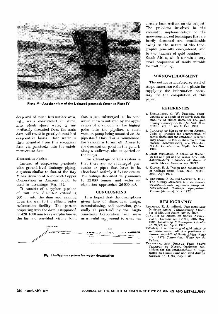
Plate V-Another view of the L-shaped penstock shown in Plate IV
deep and of much less surface area,with walls constructed of slime,into which slimy water is im-mediately decanted from the maindam, will result in greatly diminishedevaporative losses. Clear water isthen decanted from this secondarydam via penstocks into the catch-ment-water dam.
Decantation System
Instead of employing penstockswith ground-level drainage piping,a system similar to that at the RayMines Division of Kennecott CopperCorporation in Arizona could beused to advantage (Fig. ll).
It consists of a syphon pipelineof 750 mm diameter extending300 m into the dam and runningdown the wall to the effluent-waterreclamation facility. The portionprojecting into the dam is supportedon 426 1500 mm Navy-surplus buoys,the far end provided with a bend
£ """""""".
that is just submerged in the pondwater. Flow is initiated by the appli-cation of a vacuum at the highestpoint into the pipelin9, a smallvacuum pump being mounted on thepipe itself. Once flow is commenced,the vacuum is turned off. Access tothe decantation point in the pond isalong a walkway, also supported onthe buoys.
The advantage of this system isthat there are no submerged pen-stocks or pipes that have to beaban:loned entirely if failure occurs.The tailings deposited daily amountto 22 000 tonn9s, and water re-clamation approaches 26500 m3.
CONCLUSIONSIt is hoped that the descriptions
given here of slimes-dam design,commissioning, and operation, gen-erally as practised by the AngloAmerican Corporation, will serveas a useful supplement to what has
' '" ", .
"
c""~".".:". W<':-
""",-
Fig, I I-Syphon system for water decantation
284 FEBRUARY 1974
already been written on the subject'The problems involved in thesuccessful implementation of themore-mechanized techniques that arebriefly discussed are considerableowing to the nature of the topo-graphy generally encountered, andto the fineness of gold residues inSouth Africa, which contain a verysmall proportion of sands suitablefor wall building.
ACKNOWLEDGEMENT
The author is indebted to staff ofAnglo American reduction plants forsupplying the information neces-sary for the compilation of thispaper.
REFERENCES1. DONALDSON, G. W. Practical obser-
vations as a result of research into thestability of slimes dams for the goldmining industry. J. S. Afr. Inst. Min.Metall., vol. 61, no. 3. Oct. 1960.
2. CHAMBER OF MINES OF SOUTH AFRICA.Code of practice for construction ofslimes dams and the condition in whichthey should be left at the time of mineclosure. Johannesburg, the Chamber,G.P.C. Circular, no. 92/68, 1st Nov.1968.
3. Draft regulation in terms of Section26 (c) and (d) of the Water Act 1956.Johannesburg, Chamber of Mines ofSouth Africa, Circular no. 36/72.
4. KLOHN, E. J. Design and constructionof tailings dams. Can. Min. Metall.Bull., Apr. 1972.
5. BRAWNER, C. 0., and CAMPBELL, D. B.The tailings structure and its charac-teristics-a soils engineer's viewpoint.International Tailings Symposium,Tucson (Arizona), Nov. 1972.
BIBLIOGRAPHYADAMSON, R. J. (editor). Gold metallurgy
in South Africa. Johannesburg, Cham-ber of Mines of South Africa, 1972.
CHAMBER OF MINES OF SOUTH AFRICA.T.A.C. Circular no. 127/68, 29th May,1968. Consulting Metallurgists Circularno. 21/72, 7th April, 1972.
THOMAS, B. A. Planning of gold mines tominimise water pollution problems atclosure. Republic of South Africa WaterYear 1970 Convention: Water for the
Future.TRANSVAAL AND ORANGE FREE STATE
CHAMBER OF MINES. Optimum con-ditions for the establishment of vege-tation On slimes dams and sand dumps.Circular no. 1l/67, Sep. 1967.
JOURNAL OF THE SOUTH AFRICAN INSTITUTE OF MINING AND METALLURGY