Embed Size (px)
Citation preview

INSIGHT
AND
OVERVIEW
Slide Show 14:
Bulk Configuration with
the Group Object

The Group object - defined
What is a Group ?
• A collection of related objects and descriptorsto be reused as one entity
• Implicitly collects all dependants
– Templates, alarm numbers, report formats, VBA code, etc.
• Name substitution and PLC address substitution rules are first defined and enforced on the fly
• Typically a mimic of a physical unit, f.ex. a pump station

Use cases – Scenario 1
Typical use cases - Replication of similar diagrams

Use cases – Scenario 2
Typical use cases - Workgroup approach
Three system
designers
Three configurations
collected in one
master configuration
Master built from
Group export files
(.cgf)
An area in IGSS canbe exported to a .cgf file.

Use cases – Scenario 3
Typical use cases - Library of templates
Two template
Groups arecreated separately and are put intothe master Group

Characteristics of a Group
• Cannot be represented by one unique descriptor. Instead the Group typically contains a set of descriptors with underlying objects.
• Will always be created in the Global area
• A set of name and PLC addressing substitution rules can be set up for a Group allowing you to reuse the Group members again and again.

Reusable Diagrams (1)
Definition
A diagram which can show multiple sets of objects (defined as Group objects) bound to one set of graphical references (descriptors)
Use
When you need to create multiple diagrams that are identical with the exception of the underlying objects.Instead of making many diagrams, you show multiple sets of objects on the same diagram.

Workflow in Definition3. Create a control group from
the objects on the diagram via
Add Selected Objects
5. In the Diagram Properties
dialogue, select "Reusable
diagram" and select the
control group from Step 3.
1. Create a standard
diagram
2. Place objects and
graphical references on
diagram
4. Define the name
convention and PLC
address substitution
6. Use the Replicate Group
button to replicate the
control group.
8. A new group based on
the control group is created
and inserted on the
diagram.
9. Repeat steps 6 to 7 for all
the groups you want the
operator to be able to view
on the reusable diagram.
7. In the "Modify Options of
Group Members" dialogue,
enter the name and PLC
address substitutes.
Reusable diagram
New option in Diagram Properties
Control Group
Parent Group bound to diagram
Replicate Group
New button in Diagram Properties
Scenario: Three pump stations
STEP 1:
Select all objects on the
basis diagram

Scenario: Three pump stations
STEP 2:
Click ”Add Selected Objects”

Scenario: Three pump stations
STEP 3:
Define object name
and PLC addressing substitutes
New options
”Exclude templates from substitution”
”Modify object descriptions as well”
”Paste/reimport objects only”
”Do not paste the group itself”

Scenario: Three pump stationsSTEP 4:
Choose ”Reusable diagram” and
”PST01-GRP” as control groupSTEP 5:
Click ”Replicate
Group” for
the required number
of groups to display
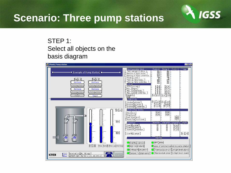
Scenario: Three pump stations
STEP 6:
Press F5 to refresh the diagram.
Choose the relevant set of objects.
Same dialogue in Definition and Supervise

Workflow in SuperviseSTEP 1:
Select the diagram
(menu or button)
Press F5 to choose a
new set of objects

Workflow in Supervise
The members from PST02-GRP are shown on the diagram.

Linked Group Objects
Definition
A linked Group object is a member of a family of linked
Group objects. The family consists of any number of Group
objects which you can update simultaneously and
dynamically.
The functionality allows you to update the properties of
existing objects and to add new objects to the Groups in
the family.
The family consists of a parent Group from which any
number of child Groups can be created. When you make a
change in one of the Groups, the change can be
distributed to all the other Groups in the family.

Parent and Child Groups
Original members in black
New/reimported objects in yellow
Scenario
PST01-q3 is added to
parent Group and reimported
to child Groups.

Workflow (1)
Create Parent – Import Child
Create the basis
diagram
Add the objects to
the parent Group
Define name and
PLC address
substitution rules
Export the parent
Group as a .cgf
file
Import the .cgf file
thus creating the
child Group
Substitute names
and PLC
addresses
Repeat previous
step for the
required no. of
child Groups

Workflow (2)
Add Object – Reimport Child
Add new object to
basis diagram
Add new object to
parent Group
Export the
changed Group to
.cgf file
Re-import the
child Groups
The new object is
now added to
each child Group

Scenario: Updating a family of
linked Group objects
STEP 1:
Select all objects on
basis diagram

Scenario: Updating a family of
linked Group objects
STEP 2:
Create the Group and
Add Selected Objects

Scenario: Updating a family of
linked Group objects
STEP 3:
Define object
name and
PLC addressing
substitutes

Scenario: Updating a family of
linked Group objects
STEP 4:
Export the parent
Group (PST01-
GRP)
STEP 5:
Import PST01-GRP.cgf
to create the child
Groups
PST02-GRP and
PST03-GRP,
respectively

Scenario: Updating a family of
linked Group objects
STEP 6:
Define the paste
options for the
child Groups
(Paste objects
only)

Scenario: Updating a family of
linked Group objects
STEP 7:
Define substitutes
for object names
and PLC
addresses

Scenario: Updating a family of
linked Group objects
STEP 8:
Make diagram
reusable and select
control group
(PST01-GRP)

Scenario: Updating a family of
linked Group objects
STEP 9:
Test that all
three Groups
are displayed

Scenario: Updating a family of
linked Group objects
STEP 10:
Create new object on
basis diagram
(PST01-q1)
STEP 11:
Add new object to parent
Group
(Add Selected Objects)

Scenario: Updating a family of
linked Group objects
STEP 13:
Reimport new
object into the
other Groups
in the family.
STEP 14:
Press F5 to refresh
the diagram and
select ”PST02-
GRP”.
New object PST02-
q1 appears.
STEP 12:
Export the updated
Group and overwrite
the existing PST01-GRP.cgf

Instructor demo
Create and update a family of linked group objects(Based on ”Pump Station” diagram in the IGSS demo project)
Do Exercise 10 in the Exercises booklet