Embed Size (px)
Citation preview

SKF Machine Condition Transmitters (MCT) Series
IntroductionThe CMSS 500 Series of SKF Machine Condition Transmitters (MCT) are 4-20 mA Transmitters. They convert part of the input signal to a 4-20 mA output proportional to the overall measurement and can be directly interfaced to an existing process control system (PLC or DCS). Combining transmitters with a Programmable Logic Controller (PLC) or a Distributed Control System (DCS) results in a high density, low cost vibration monitoring system.
FeaturesLow Cost System for Continuous Condition Monitoring
With Alert and Danger Alarms as two independent set points with LED alarm indicators and output relay contactsTrip MultiplyRemote ResetFault Detection
Compact DIN-Rail Mount, for both “G”-Rail and “T”-RailTwo Buffered Acceleration Outputs4-20 mA DC Output SignalSmall Size Due to Surface Mount Technology (SMT)
The MCT modules have a number of factory set and user selectable configuration options to tailor the modules to the specific application needs. Furthermore the MCTs can be ordered as a price sensitive basic model or as a stand alone Monitor.
The basic model provides a sensor input, a buffered BNC output, a buffered screw-terminal output and a 4-20 mA output suitable for a direct connection to a process control system.
When ordered with the Monitor option, the unit includes in addition an alarm module front panel, trip-multiply function, two alarm relays and one transducer ‘OK’ relay. The alarm module has a front panel accessible BNC
•
–
–––
•
•••
connector and an associated selector switch for reading the current vibration or alarm set points (alert and danger respectively) with a standard digital voltmeter, without opening the housing.
Series of Machine Condition Transmitters (MCT) Include
CMSS 530(A) Velocity TransmitterCMSS 590(A) Enveloped Acceleration TransmitterCMSS 525(A) Acceleration TransmitterCMSS 540(A) Displacement TransmitterCMSS 545(A) Position TransmitterCMSS 570(A) Temperature Transmitter
ApprovalsThe Machine Condition Transmitters (MCT) Series is CE approved. In order to stay within the CE conformity, the
installation should be within a closed metal enclosure and shielded power and signal cables should be used. Refer to the manuals and the CE approved installation guide supplied with the unit(s) for installations details.
Other MCT module system components, including power supplies and sensor, must also be CE approved for the industrial environment.
The CSA electrical safety approval is pending.
••
••••
IntroductionThe Machine Condition Transmitter (MCT) CMSS 530 is a 4-20 mA Velocity Transmitter. It converts part of the wide-band input signal to a signal proportional to the RMS or Peak (True Peak) value of the velocity signal and can be directly interfaced to a process control system (PLC or DCS).
Functional DescriptionAccelerometers with a built-in amplifier (ICP), a Velocity Transducer or an Electromechanical Pick Up Sensor are input for the CMSS 530 Velocity Module. The conversion of the pre-amplified wide-band raw signal to a standard ISO or non-standard velocity signal is done by filtering, integration and analog true RMS or True Peak conversion. The full-scale value for the velocity signal is converted to a 4-20 mA DC output current and can be further converted to a 1-5 V DC output voltage by using a 250-Ohm precision resistor.
With the Monitor, option the derived velocity signal is compared with the alert and danger alarm level preset (set points). These set points are adjustable via two front panel accessible potentiometers, from 0 to 110% of full scale and directly measured on the BNC output connector of the monitor module. Each has an adjustable delay of 0.1 to 10 seconds. Relay contacts can be independently configured by the user for either Normally Open (NO) (standard) or Normally Closed (NC) operation. Relays are normally de-energized and can be configured for latching or non-latching (standard) operation. Latched alarms may be reset locally or by remote contact closure. Single Pole Double Throw (SPST) output relay contacts are rated 5 Amps at 30 Vdc or 125 Vac for resistive loads. The Monitor option also provides the Trip Multiply feature, basically a set point multiplication of either 2x or 3x via contact closure.
The second BNC connector mounted on the front of the Transmitter unit provides
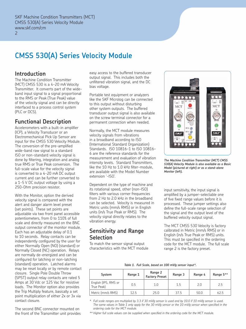
The Machine Condition Transmitter (MCT) CMSS 530(A) Velocity Module is also available as a Basic Model (pictured at right) or as a stand-alone Monitor (left).
CMSS 530(A) Series Velocity Module
easy access to the buffered transducer output signal. This includes both the unfiltered vibration signal, and the DC bias voltage.
Portable test equipment or analyzers like the SKF Microlog can be connected to this output without disturbing other system outputs. The buffered transducer output signal is also available on the screw terminal connector for a permanent connection when needed.
Normally, the MCT module measures velocity signals from vibrations in a broadband according to ISO (International Standard Organization) Standards. ISO 10816-1 to ISO 10816-6 are the reference standards for the measurement and evaluation of vibration intensity levels. Standard Transmitters, like the 10 Hz to 1.0 kHz filter-module, are available with the Model Number extension ‘-ISO’.
Dependent on the type of machine and its rotational speed, other (non-ISO) filters with various corner frequencies from 2 Hz to 2.0 kHz in the broadband can be selected. Velocity is measured in Metric units (mm/s RMS) or in English units (in/s True Peak or RMS). The velocity signal directly relates to the vibration energy.
Sensitivity and Range SelectionTo match the sensor signal output characteristics with the MCT module
* Fullscalerangesaremultipliedby3.3if30mV/gsensorisusedandby10.0if10mV/gsensorisused.ThesamevaluesinTable1onlyapplyforthe30mV/gsensororthe10mV/gsensorwhenspecifiedintheorderingcodefortheMCTmodule.
**HigherfullscalevaluescanbesuppliedwhenspecifiedintheorderingcodefortheMCTmodule.
System Range 1Range 2
Factory PresetRange 3 Range 4 Range 5**
English (IPS, RMS or True Peak) 0.5 1.0 1.5 2.0 2.5
Metric (mm/s RMS) 12.5 25.0 37.5 50.0 62.5
Table 1. Full Scale, based on 100 mV/g sensor input*.
input sensitivity, the input signal is amplified by a jumper-selectable one of five fixed range values before it is processed. These jumper settings also define the full-scale range selection of the signal and the output level of the buffered velocity output signal.
The MCT CMSS 530 Velocity is factory calibrated in Metric (mm/s RMS) or in English (in/s True Peak or RMS) units. This must be specified in the ordering code for the MCT module. The full scale range 2 is the factory preset.
SKF Machine Condition Transmitters (MCT)CMSS 530(A) Series Velocity Modulewww.skf.com/cm2

SKF Machine Condition Transmitters (MCT)CMSS 530(A) Series Velocity Module
www.skf.com/cm3
CMSS 530(A) Series Velocity Module
SpecificationsPOWER REQUIREMENTSSupply Voltage: +24 V DC (23 V to 28 V). Reverse polarity and transient protection included.Supply Current: CMSS 530 – 55 mA CMSS 530A – 110 mATotal Power: 3.1 W maximumExternal Fuse: F250 mA/250 VRelay Ratings:Switching Voltage: 30 V DC maximum or 125 V ACSwitching Current: 5 A maximum
INPUTSensor: Accelerometer, Velocity Transducer or Electromechanical Pick UpSensor Sensitivity: 100 mV/g, 100 mV/in/sec, 500 mV/in/sec; or specified.
TIP – Forrollingelementbearingapplicationswithhighvibrationlevels,beforeusingasensorwithlesssensitivity,selectahigherfull-scaleofupto5.0in/sec.
Sensor Approvals: For CE approved systems, the sensor must be CE approved.
Ordering InformationThe ordering code for the MCT CMSS 530 Velocity Module includes information about its basic measurement system and filter options.
Storage Temperature: -67 °F to +257 °F (-55 °C to +125 °C)Relative Humidity: 0-95% Relative Humidity Non-Condensing
MECHANICALWeight: 6.0 Ounces (170 Grams)Enclosure: Thermoplast ABS Color: Black, with gray front panelConnectors: 12-pole screw terminal, 2 BNC’s and two 6-pole pluggable connectors. Mounting: 32mm (G style) or 35mm (T style) DIN-RailDimensions: Length: 3.11 inches (79 mm) Base: 1.80 inches (46 mm) Height: 3.95 inches (100 mm)
Sensor OK Detection: Continuously monitors the transmitter bias and signal voltage. If this voltage exceeds preset limits, the 4-20 mA output current is reduced to less than 2 mA (typically 0 mA).
OUTPUTBuffered Acceleration Output: BNC Connector, Screw terminalSensitivity: Depending on used sensor input sensitivity, ± 10%4-20 mA DC Output: 4-20 mA proportional to the full-scale range.Accuracy: ± 0.5% of full-scale range.
TIP – Aprecision250Ohmresistorwillconvertthe 4-20mAcurrentreadingintoa1-5VdcreadingsuitableforadirectconnectiontoaProgrammableLogicController(PLC)oraDistributedControlSystem(DCS).
ENVIRONMENTALOperating Temperature: -4 °F to +176 °F (-20 °C to +80 °C)
Example: CMSS 530A100A-ER-ISO Velocity Transmitter with Monitor (Stand-Alone). Input 100 mV/g Accelerometer, English System, RMS Detection and ISO Filter Band From 10 Hz to 1.0 kHz.
AccessoriesCMSS 500-HSG-00 NEMA 4 (Steel box, painted), IP 66, no BNC’s, houses one (1) to four (4) MCT’s with companion monitor. Includes Power Supply and Wire Kit.
CMSS 500-PWRSUP +24 Vdc, 600 mA Power Supply, adequate for up to four (4) MCT’s with companion monitor, CE certified.CMSS 500-WIRE Wire kit, color coded to wire four (4) MCT’s.
CMSS 500-INSTALL Installation charge for factory installation and wiring of MCT Modules. (MCT Modules must be ordered separately.)
•
–
–
•
SKF Machine Condition Transmitters (MCT)CMSS 590(A) Enveloped Acceleration Modulewww.skf.com/reliability4
may be reset locally or by remote contact closure. SPST (Single Pole Double Throw) output relay contacts are rated 5 Amps at 30 Vdc or 125 Vac for resistive loads. The Monitor option also provides the Trip Multiply feature, basically a set point multiplication of either 2x or 3x via contact closure.
The second BNC connector mounted on the front of the Transmitter unit provides easy access to the buffered transducer output signal. This includes both the unfiltered acceleration signal, and the DC bias voltage. Portable test equipment or analyzers like the SKF Microlog can be connected to this output without disturbing other system outputs. The buffered transducer output signal is also available on the screw terminal connector for a permanent connection when needed.
Sensitivity and Range SelectionTo match the sensor signal output characteristics with the MCT module input sensitivity, the input signal is amplified by a jumper-selectable one of three fixed range values before it is processed. These jumper settings also define the full-scale range of the signal.
Table 1. Full-Scale, based on 100 mV/g sensor input*.
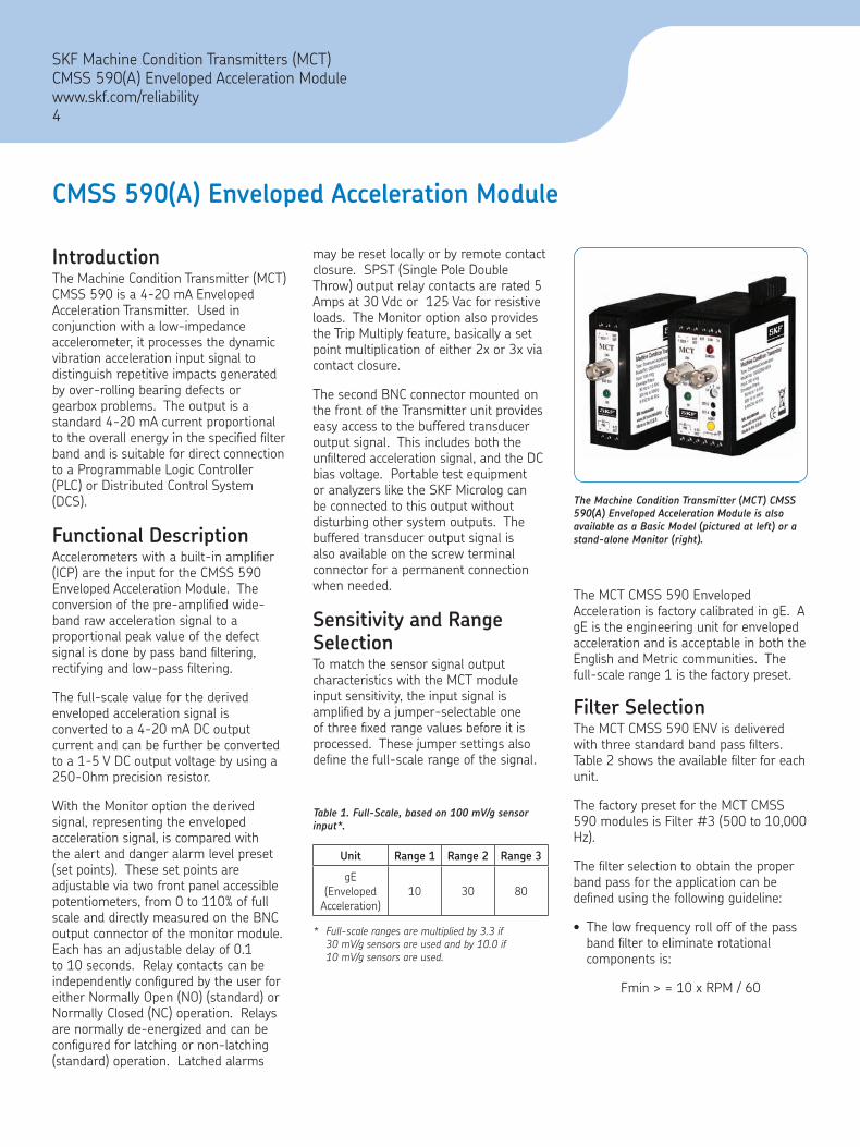
The Machine Condition Transmitter (MCT) CMSS 590(A) Enveloped Acceleration Module is also available as a Basic Model (pictured at left) or a stand-alone Monitor (right).
The MCT CMSS 590 Enveloped Acceleration is factory calibrated in gE. A gE is the engineering unit for enveloped acceleration and is acceptable in both the English and Metric communities. The full-scale range 1 is the factory preset.
Filter SelectionThe MCT CMSS 590 ENV is delivered with three standard band pass filters. Table 2 shows the available filter for each unit.
The factory preset for the MCT CMSS 590 modules is Filter #3 (500 to 10,000 Hz).
The filter selection to obtain the proper band pass for the application can be defined using the following guideline:
The low frequency roll off of the pass band filter to eliminate rotational components is:
Fmin > = 10 x RPM / 60
•
IntroductionThe Machine Condition Transmitter (MCT) CMSS 590 is a 4-20 mA Enveloped Acceleration Transmitter. Used in conjunction with a low-impedance accelerometer, it processes the dynamic vibration acceleration input signal to distinguish repetitive impacts generated by over-rolling bearing defects or gearbox problems. The output is a standard 4-20 mA current proportional to the overall energy in the specified filter band and is suitable for direct connection to a Programmable Logic Controller (PLC) or Distributed Control System (DCS).
Functional DescriptionAccelerometers with a built-in amplifier (ICP) are the input for the CMSS 590 Enveloped Acceleration Module. The conversion of the pre-amplified wide-band raw acceleration signal to a proportional peak value of the defect signal is done by pass band filtering, rectifying and low-pass filtering.
The full-scale value for the derived enveloped acceleration signal is converted to a 4-20 mA DC output current and can be further be converted to a 1-5 V DC output voltage by using a 250-Ohm precision resistor.
With the Monitor option the derived signal, representing the enveloped acceleration signal, is compared with the alert and danger alarm level preset (set points). These set points are adjustable via two front panel accessible potentiometers, from 0 to 110% of full scale and directly measured on the BNC output connector of the monitor module. Each has an adjustable delay of 0.1 to 10 seconds. Relay contacts can be independently configured by the user for either Normally Open (NO) (standard) or Normally Closed (NC) operation. Relays are normally de-energized and can be configured for latching or non-latching (standard) operation. Latched alarms
CMSS 590(A) Enveloped Acceleration Module
Unit Range 1 Range 2 Range 3
gE (Enveloped
Acceleration)10 30 80
* Full-scalerangesaremultipliedby3.3if 30mV/gsensorsareusedandby10.0if 10mV/gsensorsareused.

Band Number (Microlog)
Band Pass Filter Frequency (Hz)
Setting of Fmax in Microlog for
Comparison (Hz)
Filter Option (MCT)
Jumper
#2 50 to 1,000 100 -44 E4 and E7
#3 500 to 10,000 1,000 -66 E3 and E6
#4 5,000 to 40,000 10,000 -88 E2 and E5
Table 2. Integrated Enveloped Acceleration Filter.
SKF Machine Condition Transmitters (MCT)CMSS 590(A) Enveloped Acceleration Module
www.skf.com/reliability5
SpecificationsPOWER REQUIREMENTSSupply Voltage: +24 V DC (23 V to 28 V). Reverse polarity and transient protection includedSupply Current: CMSS 590 – 75 mA maximum CMSS 590A – 125 mA maximumTotal Power: 3.5 W maximumExternal Fuse: F250 mA/250 VRelay Ratings:Switching Voltage: 30 V DC maximum or 125 V ACSwitching Current: 5 A maximum
INPUTSensor: AccelerometerSensor Sensitivity: 100 mV/g
TIP – Toachievegreaterfull-scalevalues(greaterthan80g)connecta30mV/gsensor.
Sensor Approvals: For CE approved systems, the sensor must be CE approved.Sensor OK Detection: Continuously monitors the transmitter bias and signal voltage. If this voltage exceeds pre-set limits, the 4-20 mA output current is reduced to less than 2 mA (typically 0 mA).
OUTPUTBuffered Acceleration Output: BNC Connector, Screw terminalSensitivity: Depending on used sensor input sensitivity, ± 10%
CMSS 590(A) Enveloped Acceleration Module
4-20 mA DC Output: 4-20 mA proportional to the full-scale range.Accuracy: ± 0.5% of full-scale range.
TIP – Aprecision250-Ohmresistorwillconvertthe4-20mAcurrentreadingintoa1-5VdcreadingsuitableforadirectconnectiontoaProgrammable LogicController(PLC)oraDistributedControlSystem(DCS).
ENVIRONMENTALOperating Temperature: -4 °F to +176 °F (-20 °C to +80°C)Storage Temperature: -67 °F to +257 °F (-55 °C to +125 °C)Relative Humidity: 0-95% Relative Humidity Non-Condensing
MECHANICALWeight: 6.0 Ounces (170 Grams)Enclosure: Thermoplast ABSColor: Black, with gray front panelConnectors: 12-pole screw terminal, 2 BNC’s and two 6-pole pluggable connectors.Mounting: 32 mm (G style) or 35 mm (T style) DIN-RailDimensions: Length: 3.11 inches (79 mm) Base: 1.80 inches (46 mm) Height: 3.95 inches (100 mm)
Ordering InformationCMSS 590A100A Enveloped Acceleration Transmitter Stand-Alone Monitor. Input 100 mV/g Accelerometer.CMSS 590-100A Enveloped Acceleration Transmitter Basic Model. Input 100 mV/g Accelerometer.The ordering code for the Machine Condition Transmitter (MCT) CMSS 590 Enveloped Acceleration Module includes information about which model, basic or stand-alone unit, and its input sensitivity.
Example: Ordering the MCT with the Model Number CMSS 590A100A specifies a stand-alone enveloped acceleration transmitter configured to use with a 100 mV/g low-impedance, constant current powered accelerometer.
AccessoriesCMSS 500-HSG-00 NEMA 4 (Steel box, painted), IP 66, no BNC’s, houses one (1) to four (4) MCT’s with companion monitor. Includes Power Supply and Wire Kit.
CMSS 500-PWRSUP +24 Vdc, 600 mA Power Supply, adequate for up to four (4) MCT’s with companion monitor, CE certified.CMSS 500-WIRE Wire kit, color coded to wire four (4) MCT’s.
CMSS 500-INSTALL Installation charge for factory installation and wiring of MCT Modules. (MCT Modules must be ordered separately.)
•
•
•
–
–
•
IntroductionThe CMSS 525(A) Series are vibration acceleration transmitters/monitors. They are compatible with piezo, voltage output accelerometer inputs, they provide a 4-20 mA output proportional to the overall measurement. Each unit provides power for the associated transducer, processes the vibration signal to determine overall amplitude, and outputs a 4-20 mA dc current that is proportional to a user specified range such as 0-10 g’s in RMS Peak detection. Combining transmitters with an existing PLC or DCS system results in a high density, low cost vibration monitoring system. When specified with the alarm feature, the unit functions as a complete single channel monitor that includes alert and danger alarms, and output relays.
Buffered OutputA BNC connector mounted on the front of the unit provides access to the buffered transducer output signal. This includes both the unfiltered vibration signal, and the DC bias voltage. Portable test equipment or analyzers can be connected to this output without disturbing other system outputs.
Fault DetectionOn board fault detection circuitry continuously monitors the transducer for normal operation. If a fault occurs, the output current is reduced to 2 mA to indicate the fault to the readout system. A red LED on the front of the unit is turned on to provide a local indication of the fault.
FiltersFor applications that require monitoring specific frequency bands, optional high-pass and low-pass filters can be ordered. These filters are modular and can be installed in the field.
Each module attenuates out-of-band signals at a rate of approximately 24 dB/ octave. Corner frequencies from 2 Hz to 20 kHz may be specified. Filter modules may be cascaded to form higher order filters or to create a band-pass response. Filtering does not effect the buffered transducer output.
AlarmsThis monitoring option adds two independent set points, with LED alarm indicators and output relay contacts (Alert and Danger). Set points are adjustable via potentiometer, from 0 to 110% of full scale. Each has an adjustable delay of 1 to 10 seconds. Relay contacts can be independently configured by the user for either Normally Open (NO) (standard) or Normally Closed (NC) operation.
Relays are normally de-energized and can be configured for latching or non-latching (standard) operation. Latched alarms may be reset locally or by remote contact closure. SPST Relay contacts are rated 5 Amps at 30 Vdc or 125 Vac for resistive loads. The Alarm option also provides set point multiplication of 3x via contact closure (2x available).
Displays and AssembliesVarious display options, NEMA and explosion-proof enclosures, and assembled multi-channel systems are available. Consult your SKF Reliability Systems Sales Representative.
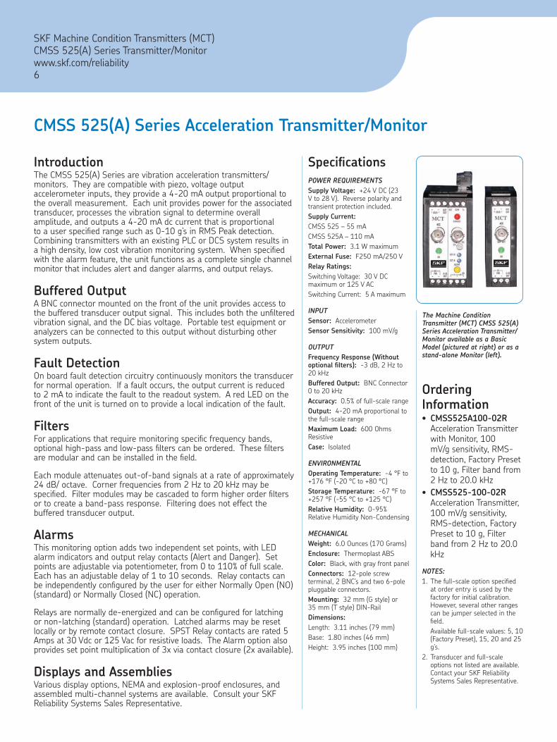
The Machine Condition Transmitter (MCT) CMSS 525(A) Series Acceleration Transmitter/Monitor available as a Basic Model (pictured at right) or as a stand-alone Monitor (left).
Ordering Information
CMSS525A100-02R Acceleration Transmitter with Monitor, 100 mV/g sensitivity, RMS-detection, Factory Preset to 10 g, Filter band from 2 Hz to 20.0 kHzCMSS525-100-02R Acceleration Transmitter, 100 mV/g sensitivity, RMS-detection, Factory Preset to 10 g, Filter band from 2 Hz to 20.0 kHz
NOTES:1. The full-scale option specified
at order entry is used by the factory for initial calibration. However, several other ranges can be jumper selected in the field.
Available full-scale values: 5, 10 (Factory Preset), 15, 20 and 25 g’s.
2. Transducer and full-scale options not listed are available. Contact your SKF Reliability Systems Sales Representative.
•
•
CMSS 525(A) Series Acceleration Transmitter/Monitor
SKF Machine Condition Transmitters (MCT)CMSS 525(A) Series Transmitter/Monitorwww.skf.com/reliability6
SpecificationsPOWER REQUIREMENTSSupply Voltage: +24 V DC (23 V to 28 V). Reverse polarity and transient protection included.Supply Current:CMSS 525 – 55 mACMSS 525A – 110 mATotal Power: 3.1 W maximumExternal Fuse: F250 mA/250 VRelay Ratings:Switching Voltage: 30 V DC maximum or 125 V ACSwitching Current: 5 A maximum
INPUTSensor: AccelerometerSensor Sensitivity: 100 mV/g
OUTPUTFrequency Response (Without optional filters): -3 dB, 2 Hz to 20 kHzBuffered Output: BNC Connector 0 to 20 kHzAccuracy: 0.5% of full-scale rangeOutput: 4-20 mA proportional to the full-scale rangeMaximum Load: 600 Ohms ResistiveCase: Isolated
ENVIRONMENTALOperating Temperature: -4 °F to +176 °F (-20 °C to +80 °C)Storage Temperature: -67 °F to +257 °F (-55 °C to +125 °C)Relative Humidity: 0-95% Relative Humidity Non-Condensing
MECHANICALWeight: 6.0 Ounces (170 Grams)Enclosure: Thermoplast ABSColor: Black, with gray front panelConnectors: 12-pole screw terminal, 2 BNC’s and two 6-pole pluggable connectors. Mounting: 32 mm (G style) or 35 mm (T style) DIN-RailDimensions:Length: 3.11 inches (79 mm)Base: 1.80 inches (46 mm)Height: 3.95 inches (100 mm)
SKF Machine Condition Transmitters (MCT)CMSS 540(A) Series Displacement Transmitter/Monitor
www.skf.com/reliability7
IntroductionThe CMSS 540(A) Series are displacement transmitters/monitors. They are compatible with proximity (eddy) probe inputs, they provide a 4-20 mA output proportional to the overall measurement. Each unit provides power for the associated transducer, processes the vibration signal to determine overall amplitude, and outputs a 4-20 mA dc current that is proportional to a user specified range such as 10 mils peak-to-peak detection. Combining transmitters with an existing PLC or DCS system results in a high density, low cost vibration monitoring system. When specified with the alarm feature, the unit functions as a complete single channel monitor that includes alert and danger alarms, and output relays.
Buffered OutputA BNC connector mounted on the front of the unit provides access to the buffered transducer output signal. This includes both the unfiltered vibration signal, and the DC bias voltage. Portable test equipment or analyzers can be connected to this output without disturbing other system outputs.
Fault DetectionOn board fault detection circuitry continuously monitors the transducer for normal operation. If a fault occurs, the output current is reduced to 2 mA to indicate the fault to the readout system. A red LED on the front of the unit is turned on to provide a local indication of the fault.
FiltersFor applications that require monitoring specific frequency bands, optional high-pass and low-pass filters can be ordered. These filters are modular and can be installed in the field.
Each module attenuates out-of-band signals at a rate of approximately 24 dB/octave. Corner frequencies from 2 Hz to 20 kHz may be specified. Filter modules may be cascaded to form higher order filters or to create a band-pass response. Filtering does not effect the buffered transducer output.
AlarmsThis monitoring option adds two independent set points, with LED alarm indicators and output relay contacts (Alert and Danger). Set points are adjustable via potentiometer, from 0 to 110% of full scale. Each has an adjustable delay of 1 to 10 seconds. Relay contacts can be independently configured by the user for either Normally Open (NO) (standard) or Normally Closed (NC) operation.
Relays are normally de-energized and can be configured for latching or non-latching (standard) operation. Latched alarms may be reset locally or by remote contact closure. SPST Relay contacts are rated 5 Amps at 30 Vdc or 125 Vac for resistive loads. The Alarm option also provides set point multiplication of 3x via contact closure (2x available).
Displays and AssembliesVarious display options, NEMA and explosion-proof enclosures, and assembled multi-channel systems are available. Consult your SKF Reliability Systems Sales Representative.
CMSS 540(A) Series Displacement Transmitter/Monitor
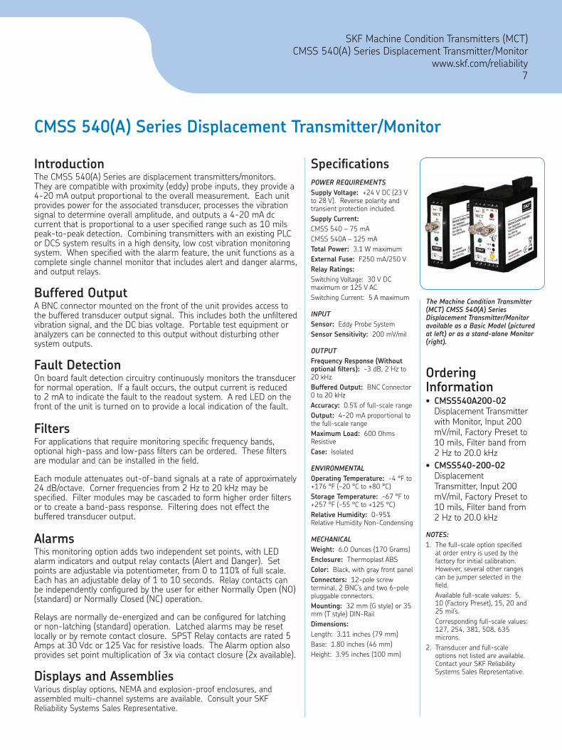
The Machine Condition Transmitter (MCT) CMSS 540(A) Series Displacement Transmitter/Monitor available as a Basic Model (pictured at left) or as a stand-alone Monitor (right).
Ordering Information
CMSS540A200-02 Displacement Transmitter with Monitor, Input 200 mV/mil, Factory Preset to 10 mils, Filter band from 2 Hz to 20.0 kHzCMSS540-200-02Displacement Transmitter, Input 200 mV/mil, Factory Preset to 10 mils, Filter band from 2 Hz to 20.0 kHz
NOTES:1. The full-scale option specified
at order entry is used by the factory for initial calibration. However, several other ranges can be jumper selected in the field.
Available full-scale values: 5, 10 (Factory Preset), 15, 20 and 25 mil’s.
Corresponding full-scale values: 127, 254, 381, 508, 635 microns.
2. Transducer and full-scale options not listed are available. Contact your SKF Reliability Systems Sales Representative.
•
•
SpecificationsPOWER REQUIREMENTSSupply Voltage: +24 V DC (23 V to 28 V). Reverse polarity and transient protection included.Supply Current:CMSS 540 – 75 mACMSS 540A – 125 mATotal Power: 3.1 W maximumExternal Fuse: F250 mA/250 VRelay Ratings:Switching Voltage: 30 V DC maximum or 125 V ACSwitching Current: 5 A maximum
INPUTSensor: Eddy Probe SystemSensor Sensitivity: 200 mV/mil
OUTPUTFrequency Response (Without optional filters): -3 dB, 2 Hz to 20 kHzBuffered Output: BNC Connector 0 to 20 kHzAccuracy: 0.5% of full-scale rangeOutput: 4-20 mA proportional to the full-scale rangeMaximum Load: 600 Ohms ResistiveCase: Isolated
ENVIRONMENTALOperating Temperature: -4 °F to +176 °F (-20 °C to +80 °C)Storage Temperature: -67 °F to +257 °F (-55 °C to +125 °C)Relative Humidity: 0-95% Relative Humidity Non-Condensing
MECHANICALWeight: 6.0 Ounces (170 Grams)Enclosure: Thermoplast ABSColor: Black, with gray front panelConnectors: 12-pole screw terminal, 2 BNC’s and two 6-pole pluggable connectors. Mounting: 32 mm (G style) or 35 mm (T style) DIN-RailDimensions:Length: 3.11 inches (79 mm)Base: 1.80 inches (46 mm)Height: 3.95 inches (100 mm)

SKF Machine Condition Transmitters (MCT)CMSS 545(A) Series Position Transmitter/Monitorwww.skf.com/reliability8
CMSS 545(A) Series Position Transmitter/Monitor
The Machine Condition Transmitter (MCT) CMSS 545(A) Series Position Transmitter/Monitor available as a Basic Model (pictured at right) or as a stand-alone Monitor (left).
Ordering Information
CMSS545A200-04 Position Transmitter with Monitor, Input 200 mV/mil, Factory preset to 0-80 mils (40-0-40)CMSS545-200-04 Position Transmitter, Input 200 mV/mil, Factory preset to 0-80 mils (40-0-40)
NOTES:1. The full-scale option specified
at order entry is used by the factory for initial calibration. However, several other ranges can be jumper selected in the field.
Full-scale values: 0-80 mils (40-0-40) (Factory Preset).
Corresponding full-scale values: 0-2.0 mm (1.0-0-1.0).
2. Transducer and full-scale options not listed are available. Contact your SKF Reliability Systems Sales Representative.
•
•
IntroductionThe CMSS 545(A) Series are position transmitters/monitors. They are compatible with proximity (eddy) probe inputs, they provide a 4-20 mA output proportional to the overall measurement. Each unit provides power for the associated transducer, processes the vibration signal to determine overall amplitude, and outputs a 4-20 mA dc current that is proportional to a user specified range such as ± 40 mils detection. Combining transmitters with an existing PLC or DCS system results in a high density, low cost vibration monitoring system. When specified with the alarm feature, the unit functions as a complete single channel monitor that includes alert and danger alarms, and output relays.
Buffered OutputA BNC connector mounted on the front of the unit provides access to the buffered transducer output signal. This includes both the unfiltered vibration signal, and the DC bias voltage. Portable test equipment or analyzers can be connected to this output without disturbing other system outputs.
Fault DetectionOn board fault detection circuitry continuously monitors the transducer for normal operation. If a fault occurs, the output current is reduced to 2 mA to indicate the fault to the readout system. A red LED on the front of the unit is turned on to provide a local indication of the fault.
AlarmsThis monitoring option adds two independent set points, with LED alarm indicators and output relay contacts (Alert and Danger). Set points are adjustable via potentiometer, from 0 to 110% of full scale. Each has an adjustable delay of 1 to 10 seconds. Relay contacts can be independently configured by the user for either Normally Open (NO) (Standard) or Normally Closed (NC) operation.
Relays are normally de-energized and can be configured for latching or non-latching (standard) operation. Latched alarms may be reset locally or by remote contact closure. SPST (Single Pole Double Throw) Relay contacts are rated 5 Amps at 30 Vdc or 125 Vac for resistive loads. The Alarm option also provides set point multiplication of 3x via contact closure (2x available).
Displays and AssembliesVarious display options, NEMA and explosion-proof enclosures, and assembled multi-channel systems are available. Consult your SKF Reliability Systems Sales Representative.
SpecificationsPOWER REQUIREMENTSSupply Voltage: +24 V DC (23 V to 28 V). Reverse polarity and transient protection included.Supply Current:CMSS 545 – 55 mACMSS 545A – 110 mATotal Power: 3.1 W maximumExternal Fuse: F250 mA/250 VRelay Ratings:Switching Voltage: 30 V DC maximum or 125 V ACSwitching Current: 5 A maximum
INPUTSensor: Eddy Probe SystemSensor Sensitivity: 200 mV/mil
OUTPUTBuffered Acceleration Output: BNC Connector, Screw terminalSensitivity: Depending on used sensor input sensitivity, ± 10%4-20 mA DC Output: 4-20 mA proportional to the full-scale rangeAccuracy: 0.5% of full-scale range
ENVIRONMENTALOperating Temperature: -4 °F to +176 °F (-20 °C to +80 °C)Storage Temperature: -67 °F to +257 °F (-55 °C to +125 °C)Relative Humidity: 0-95% Relative Humidity Non-Condensing
MECHANICALWeight: 6.0 Ounces (170 Grams)Enclosure: Thermoplast ABSColor: Black, with gray front panelConnectors: 12-pole screw terminal, 2 BNC’s and two 6-pole pluggable connectors. Mounting: 32 mm (G style) or 35 mm (T style) DIN-RailDimensions:Length: 3.11 inches (79 mm)Base: 1.80 inches (46 mm)Height: 3.95 inches (100 mm)
SKF Machine Condition Transmitters (MCT)CMSS 570(A) Series Temperature/Monitor
www.skf.com/reliability9
IntroductionThe CMSS 570(A) Series are solid state temperature transmitters/monitors. They can be used with solid-state temperature sensor or dual output vibration/temperature sensor that provides a 10 mV/K output. The input signal is processed to provide temperature in degrees F or C. The output is a standard 4-20 mA current proportional to this temperature, within the specified full-scale range of 0-250 Degrees F. The 4-20 mA output is suitable for direct connection to a Programmable Logic Controller (PLC) or Distributed Control System (DCS).
Buffered OutputA BNC connector mounted on the front of the unit provides buffered access to a 0-5 Vdc temperature proportional signal that can be read with a standard voltmeter or data analyzer (Microlog).
Fault DetectionOn board fault detection circuitry continuously monitors the transducer for normal operation. If a fault occurs, the output current is reduced to 2 mA to indicate the fault to the readout system. A red LED on the front of the unit is turned on to provide a local indication of the fault.
AlarmsThis monitoring option adds two independent set points, with LED alarm indicators and output relay contacts (Alert and Danger). Set points are adjustable via potentiometer, from 0 to 110% of full scale. Each has an adjustable delay of 1 to 10 seconds. Relay contacts can be independently configured by the user for either Normally Open (NO) (Standard) or Normally Closed (NC) operation.
Relays are normally de-energized and can be configured for latching or non-latching (standard) operation. Latched alarms may be reset locally or by remote contact closure. SPST (Single Pole Double Throw) Relay contacts are rated 5 Amps at 30 Vdc or 125 Vac for resistive loads. The Alarm option also provides set point multiplication of 3x via contact closure (2x available).
Displays and AssembliesVarious display options, NEMA and explosion-proof enclosures, and assembled multi-channel systems are available. Consult your SKF Reliability Systems Sales Representative.
CMSS 570(A) Series Temperature Transmitter/Monitor
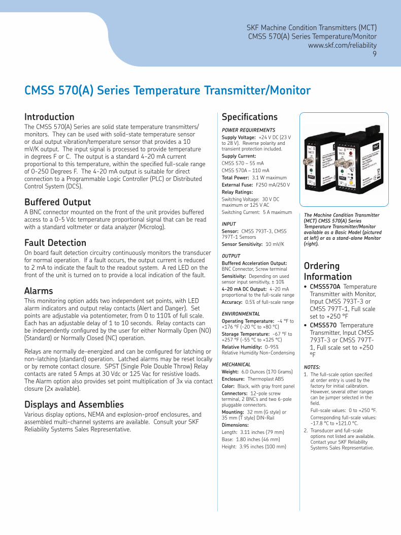
The Machine Condition Transmitter (MCT) CMSS 570(A) Series Temperature Transmitter/Monitor available as a Basic Model (pictured at left) or as a stand-alone Monitor (right).
Ordering Information
CMSS570A Temperature Transmitter with Monitor, Input CMSS 793T-3 or CMSS 797T-1, Full scale set to +250 °FCMSS570 Temperature Transmitter, Input CMSS 793T-3 or CMSS 797T-1, Full scale set to +250 °F
NOTES:1. The full-scale option specified
at order entry is used by the factory for initial calibration. However, several other ranges can be jumper selected in the field.
Full-scale values: 0 to +250 °F. Corresponding full-scale values:
-17.8 °C to +121.0 °C.2. Transducer and full-scale
options not listed are available. Contact your SKF Reliability Systems Sales Representative.
•
•
SpecificationsPOWER REQUIREMENTSSupply Voltage: +24 V DC (23 V to 28 V). Reverse polarity and transient protection included.Supply Current:CMSS 570 – 55 mACMSS 570A – 110 mATotal Power: 3.1 W maximumExternal Fuse: F250 mA/250 VRelay Ratings:Switching Voltage: 30 V DC maximum or 125 V ACSwitching Current: 5 A maximum
INPUTSensor: CMSS 793T-3, CMSS 797T-1 SensorsSensor Sensitivity: 10 mV/K
OUTPUTBuffered Acceleration Output: BNC Connector, Screw terminalSensitivity: Depending on used sensor input sensitivity, ± 10%4-20 mA DC Output: 4-20 mA proportional to the full-scale rangeAccuracy: 0.5% of full-scale range
ENVIRONMENTALOperating Temperature: -4 °F to +176 °F (-20 °C to +80 °C)Storage Temperature: -67 °F to +257 °F (-55 °C to +125 °C)Relative Humidity: 0-95% Relative Humidity Non-Condensing
MECHANICALWeight: 6.0 Ounces (170 Grams)Enclosure: Thermoplast ABSColor: Black, with gray front panelConnectors: 12-pole screw terminal, 2 BNC’s and two 6-pole pluggable connectors. Mounting: 32 mm (G style) or 35 mm (T style) DIN-RailDimensions:Length: 3.11 inches (79 mm)Base: 1.80 inches (46 mm)Height: 3.95 inches (100 mm)

SKF Machine Condition Transmitters (MCT)Vibration Sensorswww.skf.com/reliability10
Recommended Vibration Sensors
FeaturesRecommended for use with the SKF Machine Condition Transmitters (MCT)Economical, rugged, general purposeSensitivity, 100 mV/g to optimize use in most applicationsMeets stringent CE, EMC requirementsCable shield and braid connected to sensor housing for better noise rejectionCorrosion resistantMiswiring protection
•
••
••
••
CMSS 2110Industrial Acceleration Sensor with Integral 5 Meter (16.5 Feet) Over-Braided Cable
FeaturesRecommended for use with the CMSS 570(A) Series Temperature Transmitter/MonitorMeasures both temperature and accelerationRugged constructionHermetic sealGround isolatedESD protectionMiswiring protection
•
••••••
CMSS 793T-3Multifunction Sensor – Acceleration and Temperature
CMSS 797T-1Low Profile, Multifunction Sensor – Acceleration and Temperature
FeaturesRecommended for use with the CMSS 570(A) Series Temperature Transmitter/MonitorMeasures both temperature and accelerationRugged constructionCorrosion resistantHermetic sealGround isolatedESD protectionMiswiring protectionSide exit
•
••••••••
CMSS 2100Standard Industrial Acceleration Sensor
FeaturesRecommended for use with the SKF Machine Condition Transmitters (MCT)Economical, rugged, general purposeSensitivity, 100 mV/g to optimize use in multiple applicationsExceptional bias voltage (BV) stability at elevated temperaturesDesigned for exceptional low noise level for low elevated temperaturesMeets stringent CE, EMC requirementsSmaller profile industrial accelerometersTwo (2) mounting studs (1/4–28 and M8 x 1.25) providedCorrosion resistant and hermetically sealed for humidity areasReverse polarity wiring protection
•
••
•
•
•••
•
•
Applying decades of on-line and portable vibration monitoring experience, SKF has developed and can provide the epitome of industrial vibration sensors and sensor mounting accessories for your machine condition monitoring needs. Despite the advances made in vibration monitoring and analysis equipment, the selection of sensors and the way they are mounted on a machine remain critical factors in determining the success of any monitoring program. Money saved by installing inferior sensors is not a prudent investment since the information provided about the machine of interest often is not accurate or reliable. Poor quality sensors can easily give misleading data
or, in some cases, cause a critical machine condition to be completely overlooked.
The various machine operating conditions concerning temperature extremes, magnetic field, vibration range, frequency range, electromagnetic compatibility (EMC) and electrostatic discharge (ESD) conditions and signal quality, necessitates the need for a variety of sensors. Without a proper sensor to supply the critical operating information, the machine can be operating in a most hazardous condition to the machine as well as the personnel operating the machine.

SKF Machine Condition Transmitters (MCT)Eddy Probe Systems
www.skf.com/reliability11
Eddy Probe Systems (RYTON® – Based Eddy Current Transducers)
The Eddy Probe is used to measure radial or axial shaft motion. It is mounted through or to the side of a bearing cap and observes the shaft’s movement relative to its mounting position. An Eddy Probe System is comprised of a Probe, a Driver (oscillator demodulator), and an Extension Cable.
Shaft relative motion is the radial vibration of the shaft journal relative to the bearing. This method of vibration measurement is preferred for journal bearings since it directly relates to permissible clearances. In machines with relatively light rotors and stiff heavy casings (turbines and compressors), almost all of the shaft’s vibration energy is dissipated as displacement (exhibit low transmissibility), which can only be measured as shaft relative motion.
Eddy Probe Systems have excellent frequency response. They have no lower frequency limit and are used to measure shaft axial position as well as vibration.
CMSS 65/CMSS 665 Series 5 mm Eddy Probe System
A complete CMSS 65 Eddy Current Probe System is comprised of:
CMSS 65 Eddy Current ProbeCMSS 958 Extension CableCMSS 665 or CMSS 665P Driver
At +23 °C (+73 °F), with a -24 VDC supply and target of AISI 4140 steel.
•••
CMSS 68/CMSS 668 Series 8 mm Eddy Probe System
A complete CMSS 68 Eddy Current Probe System is comprised of:
CMSS 68 Eddy Current ProbeCMSS 958 Extension CableCMSS 668 or CMSS 668P Driver
At +23 °C (+73 °F), with a -24 VDC supply and target of AISI 4140 steel.
•••
FeaturesConforms to API 670 - American Petroleum Institute has published Standard 670 to define reliable protection systems for rotating equipment operating in the harsh conditions found in oil production, refining, and chemical processing.
“Super tough” RYTON® probe tips and driver case - RYTON®’s strength approaches that of metal. The material is now beginning to be used in the manufacture of automobile engine camshafts. That’s what we mean when we say “Super tough”.
DIN-Rail mounting and compression connectors for optimum installation.
Hazardous area approved units are available.
Recommended in conjunction with the CMSS 540(A) Series Displacement Transmitter/Monitor and the CMSS 545(A) Series Position Transmitter/Monitor.
•
•
•
•
•

SKF Machine Condition Transmitters (MCT) Series
MCT Integration – Enclosures/Housings Examples
Wireless MCT SystemCMSS 530 Velocity TransmitterCMSS 590 Enveloped Acceleration TransmitterWireless Ethernet Connection to Hard wired Network
•••
Typical Pump or Fan Monitoring SystemCMSS 530 Velocity TransmitterCommon Display with Channel Selector SwitchNEMA 4x Enclosure
•••
Eddy Probe SystemCMSS 530 Velocity TransmitterCMSS 545 Eddy Probe Position TransmitterIndividual Displays, NEMA 4x Enclosure
•••
12 Channels of Vibration Velocity Transmitters
CMSS 530 Velocity TransmitterCommon Display with Channel Selector SwitchNEMA 4x Enclosure
•••
Solar Gas Turbine RetrofitCMSS 530 Velocity TransmitterExplosion Proof SystemClass I, Division I, Continuous Monitoring System for Offshore InstallationI-S Barriers, Slave Relays, Independent Displays
•••
•
SKF Reliability Systems5271 Viewridge Court • San Diego, California 92123 USATelephone: +1 858-496-3400 • FAX: +1 858-496-3531
Web Site: www.skf.com/cmThe contents of this publication are the copyright of the publisher and may not be reproduced (even extracts) unless permission is granted. Every care has been taken to ensure the accuracy of the information contained in this publication but no liability can be accepted for any loss or damage whether direct, indirect or consequential arising out of the use of the information contained herein. SKF reserves the right to alter any part of this publication without prior notice.
SKF Patents include: #US05854553, #US05845230, #US06489884, #US05679900, #US04768380, #US06199422, #US05992237, #US06202491, #US06513386, #US06275781, #US06633822, #US06006164, #US2003 0178515A1, #US6,789,025, #US6,789,360, #WO 03 048714A1
• SKF and Microlog are registered trademarks of the SKF Group.• All other trademarks are the property of their respective owners.
CM2284 (Revised 9-06) • Copyright © 2006 by SKF Condition Monitoring, Inc. ALL RIGHTS RESERVED.