Embed Size (px)
Citation preview

ACI JOURNAL TECHNICAL PAPER Title no. 81-38
Size Effect in Shear Failure of Longitudinally Reinforced Beams
by Zden~k P. Ba2ant and Jin-Keun Kim
Consequences of recent fracture mechanics studies of concrete for analyzing diagonal shear failure of longitudinally reinforced beams or one-way slabs without shear reinforcement were studied. The cracking produced by shear was assumed to propagate with a dispersed zone of microcracks at the fracture front. Dimensional analysis of the energy release rate then shows that the nominal shear stress at failure should not be a constant but should vary as (1 + did. Aor', in which d = beam depths, d. = maximum aggregate size, and A 0 = constant. For relatively small beams, representing the great majority of those tested in the laboratories, the nominal stress at failure is nearly constant; however, for much deeper beams it considerably declines with increasing size. This trend is confirmed by previous experimental results. In addition to the size effect, a rational formula for the effect of steel ratio and shear span is derived. Comparisons with existing test data involving nearly 300 tests indicate that, compared to the formulas in the current building codes, the coefficient of variation of deviations from the formula is reduced to less than one-half.
Keywords: beams (supports); building codes; cracking (fracturing); dimensional analysis; failure; reinforced concrete; shear properties; statistical analysis; structural analysis.
STATEMENT OF PROBLEM Predicting brittle failures of concrete structures due
to tensile cracking of concrete is much more difficult than predicting ductile failures. The diagonal shear failure of longitudinally reinforced beams and one-way slabs without shear reinforcement is a good example. Although great progress has been achieved in various theoretical studies l
-8 and extensive experimentation,I,4,8-28
the scatter of the deviations of test results from the formulas in current building codes is enormous (see Fig. 7.13 in Reference 29) and is much larger than the scatter of tensile strength or fracture energy.
The current formulas are based on the concept of tensile strength. However, this concept is theoretically justified only in the case of ductile failures governed by the theory of plasticity. For failures in which the stress decreases after reaching the strength limit, as is the case for tensile cracking, the strength concept is inconsistent when applied in a continuum analysis. For example, finite element analysis of cracking based on the strength criterion can exhibit a strong spurious dependence on the choice of mesh size. 3o,31 As is well known from fracture mechanics, a theoretically consistent approach must be based on an energy criterion of failure.
456
Having realized this fact, ReinhardC,32 recently analyzed certain test data for diagonal shear failure on the basis of the classical (linear elastic) fracture mechanics and found a relatively good agreement with these test data. However, when some other available data are considered, the agreement with the linear elastic fracture mechanics is not very good and does not seem much better than for the strength criterion. This is not surprising, since the linear elastic fracture mechanics has been found to be inapplicable to concrete, as demonstrated, e.g., by Naus and Kesler.
The last few years, however, witnessed an increased interest in basic studies of concrete fracture, and a new form of fracture mechanics which appears applicable to concrete has emerged. This new approach does not treat fracture as a point phenomenon, but recognizes that in brittle heterogeneous materials such as concrete the fracture propagates with a relatively large fracture process zone in which progressive microcracking gradually reduces the tensile stress to zero. 33-35 The aim of this paper is to explore the consequences of this new, nonlinear fracture mechanics for diagonal shear failure. The main purpose of fracture mechanics is the prediction of the effect of structure size, and it will be seen that a considerable improvement can be brought about in this regard.
STRUCTURAL SIZE EFFECT IN FRACTURE The structural size effect may be illuminated by con
sidering structures of different sizes but geometrically similar shapes, e.g., beams of the same steel ratio and the same ratio of depth to shear span. The strength criterion may be stated as UN = Jt' where Jt' = direct tensile stength of concrete and UN = nominal stress at failure. For reasons of dimensionality, UN = cNPlbd where P = given load, d = characteristic dimension of the structure,' e.g, the depth of beam, b = thickness, and CN = constant. Thus, if one considers the plot of log UN
Received May 23, 1983, and reviewed under Instit~te publication. polici.es. Copyright © 1984, American Concrete Institute. All nghts reserved, mcludm.g the making of copies unless permission is obtained from the copyright propnetOTS. Pertinent discussion will be published in the July-August 1985 ACI JOURNAL if received by Apr. I, 1985.
Vol.SI ACI JOURNAL I September-October 1984

Zdenek P. Ba'tant, FACI. is a professor and director. Center for Concrete and Geomaterials. Northwestern University. Dr. Bazant is a registered structured engineer, serves as consultant to Argonne National Laboratory and several other firms, and is on editoral boards of five journals. He serves as chairman of RILEM Committe!;! TC69 on creep. of ASCE-EMD Committee on Properties of Materials and IA-SMiRT Division H. His works on concrete and geomaterials, inelastic behavior, fracture, and stability have been recognized by a RILEM medal, ASCE Huber Prize and T. Y. Lin Award, IR-JOO Award, Guggenheim Fellowship, Ford Foundation Fellowship, and election as Fellow of American Academy of Mechanics.
ACI member Jin-Keun Kim is a graduate research assistant and PhD candidate in civil engineering at Northwestern University. He obtained his BS and MS degrees in the Department of Architecture from Seoul National University. He has worked as a teaching assistant at Seoul National University, as an instructor at Ulsan Institute of Technology, Korea, and as a structural designer. His research interests include inelastic behavior and fracture of concrete and reinforced concrete, as well as stress-strain relations for soils.
versus log d (Fig. 1), the locus of all failure states is a horizontal line, regardless of whether one uses elastic, plastic, or some other strength-based analysis. The only difference between these types of analysis is the level at which the horizontal line is to be drawn. Fig. 1 shows examples for some elementary situations, such as bending, shear, and torsion of unreinforced beams.
For linear elastic fracture mechanics, the size effect is completely different. As is well known,32,36 aN varies inversely as $, so the plot of log aN versus log d is a straight line of slope - Y2; see Fig. 1. However, except for extremely large structure sizes, this size effect is generally too strong for concrete structures, as the subsequent analysis will confirm.
Due to the dispersed nature and progressive development of cracking in concrete, the structural size effect may be described as37
in which do is the maximum aggregate size, A is a relative structure size, and Ao is an empirical constant. The foregoing equation may be derived for various simple situations and may be also deduced in general by dimensional analysis based on a hypothesis characterizing the dispersed nature of cracking34,37 (See Appendix).
For structures of a small size relative to the size of aggregate, i.e., for small A, the value of A/Ao in Eq. (1) may be neglected in comparison to unity, and then we have ¢(A) = 1 and aN = fi = constant. This indicates that the strength criterion (horizontal line in Fig. 1) is correct for small size structures, which happens to be the case for most structures tested in laboratories. For structures of a very large size compared to the size of aggregate, 1 may be neglected in comparison to A/Ao in Eq. (1), and then aN = fi (A/'Ao)'V" which is the size effect of linear elastic fracture mechanics described by the inclined straight line in Fig. 1. Obviously, Eq. (1) represents a gradual transition from the strength criterion for small structures to the linear elastic fracture mechanics for very large structures. For A < Ao the strength criterion dominates, and for A > 'Ao the fracture mechanics aspect of failure dominates.
ACI JOURNAL I September·October 1984
6M 4M a: a-or-N bHZ bH2
linear fracture mechanics
most existing tests
nonlinear fracture mechanics
log (rill8 do)
Fig. 1 - Illustration of size effect according to various theories
EFFECT OF STEEL RATIO AND SHEAR SPAN Eq. (1) could now be combined with some existing
formula for the diagonal shear failure and compared to test data. However, the huge scatter of the data is due not only to the size effect, but also to the manner in which other factors, such as the steel ratio p and the shear span a (Fig. 2) are taken into account. Thus, to derive full benefit from a better formulation for the size effect, we should also try to improve the analysis for other influences. For that purpose we will try to use some rational, albeit crude and simplified, arguments.
Consider the end segment of a beam shown in Fig. 2(a), in which a constant shear force V acts throughout the shear span a. In general, the shear span may be defined as a = MI V where V = shear force, and M =
bending moment in the same cross section. The bending moment at any distance x from the support may be expressed as M = Tjd where d = depth of the beam, T = T(x) = tensile force resultant acting at the centroid of longitudinal reinforcement, and j = j(x) =
variable coefficient. The shear force may then be expressed as V = dMldx, and the derivative of the product may be written as a sum of two terms
dT -J'd dx '
d' V2 = JL Td (2)
dx
As known from various preceding studies,29 component VI is due to a composite beam action and arises from the transmission of a tensile force into the steel bars by means of bond stresses, and component V2 represents what is known as arch action, since it arises from an arch-like variation in the height of the location of the compressive resultant C = T.
457

(b)
I ~J L:-=4=i:..:-::..==-=-=-=-==u'='=====1 -!! .
I
Fig. 2 - Notation for the analysis of diagonal shear
We need a simple description of the function j(x), and choose for this purpose
(3)
in which jo is a constant, defining the location of the compression resultant C at the end of the shear span, x = a. According to the classical bending theory of reinforced concrete beams with only tensile reinforcement and with a negligible tensile capacity of concrete, we would have
jo = 1 - 1;3 (c/d) , c/d = (nZpZ + 2np)1h - np (4)
in which p = steel ratio, n = E/ Ec = ratio of elastic moduli of steel and concrete, and c = depth to neutral axis at x = a. Eq. (4) is, however, unnecessarily complicated and may be replaced by the following simpler expression
(5)
in which k and m are certain constants. These constants can always be chosen so that the values given by Eq. (4) and (5) are almost undistinguishable; see Fig. 3.
458
.~
.951----------:-;=:=;:;===--:-~ - ;.=1-("/ (np)2+2np-n p)/3
n=5 - - ;. =k/ p '" k=0.73 p=Asjbd
.90 ~ m=0.0"8 n=£sIEc ~ ~~
n=10 ~~ ""'" k=0.67 ~ m=0.058 ~
k.m constonta
.85
"""--
.80+-------~----~~-----+------_+--~ 0.00 .01 .02 .03 .04
p
Fig. 3 - Comparisons of two formulas for the effect of steel ratio on the arm of internal forces
For the composite beam action contribution, we may express the rate of change of the tensile force T in terms of the bond stress Ub transmitted from concrete to the steel bars, i.e., dT/dx = Co (11" E Dbub), in which Co = some constants, and E Db is the sum of the diameters of all bars in the cross section. This relation expresses the equilibrium condition of a unit segment of the steel bar in the longitudinal direction. If the concrete cross section is kept the same and the amount of reinforcement is varied, E Db is proportional to .,[p. Furthermore, the ultimate bond stress is roughly proportional to f: q where q == 0.5, so we have dT/dx = C1 .JP f: q
,
in which CI is some constant. Substituting into Eq. (2), we thus get
(6)
To express the arch action contribution to shear, we may set T = as pbd, and substituting into Eq. (2) we obtain
(7)
Experience shows that the diagonal shear failure happens by inclined cracks whose horizontal projection roughly equals beam depth d. This suggests taking x = d as the critical cross section for arch-action shear, and Eq. (7) then reduces to
(8)
Considering the steel stress as as constant, and substituting Eq. (5), we further obtain
(9)
in which Cz is some constant. Finally, summing the contributions from composite
beam action and arch action, V = VI + Vz, and calcu-
ACI JOURNAL I September-October 1984

lating the nominal shear stress at failure as v ::;: V/bd, we acquire the formula
v ::;: kl pP (fclq + k2 --JP) (10) (a/d)'
in which k2 ::;: c2/kl • This formula is similar to that used in the ACI Code,43 but it is to a greater extent based on mechanics analysis and contains more empirical parameters to be found from test results; these parameters are kh k2' p, q, and r.
The foregoing analysis did not take into account the size effect appropriate for brittle failures due to concrete cracking. According to Eq. (1), we should therefore multiply the nominal shear stress at failure by function cP(>'-.) ensuing from dimensional analysis of the energy release by fracture. Thus, we finally obtain the formula
v ::;: kl pP fclq + k2 -p- 1 + - (11) ( ro ) ( d ),V, (a/d)' >'-.od.
in which Ao represents an additional empirical parameter.
STATISTICAL ANALYSIS OF EXISTING TEST DATA
Shear failure of beams is one problem for which extensive statistical information has been accumulated over the years. This statistical basis was exploited by Zsutty38.39 for the development of a very simple prediction formula, the best one proposed up to now. His statistical analysis, however, did not particularly cover the size effect and was made before some of the important test results on the size effect became available. Eq. (11) proposed here has been compared to essentially all important experimental evidence, both that with regard to the effect of steel ratio, shear span, and concrete strength, and the more limited one with regard to the effect of size (beam depth). The test data used included those of Moody et aI., 19 Diaz de Cossio et aI., 23 MatheY,17 Van den Berg,27 Taylor, 26 Rajagopalan,22 Kani,12.13 Leonhardt and Walther, 16 Walraven,28 Tay-
~ -=-
to> .3
,1,--------:-----------, a/d=3
-.1
-.2
(a) Walraven pO.8 " 1:=4000 (pII)
----.------'~ - Itrongth ar ylold crltorion
'~.~
'"" nonlinear fractur. m.ChanIC.~ >,,_25
A,,-13.'~. linear fractur. mechanIc.
"".
lor,8 Rusch et al.,24 Bresler and Scordelis,IO Krefeld and Thurston, IS Bhal,9 Mattock,18 Placas and Regan,21 and Swamy and Qureshi. 2S
First consider the size effect, i.e., the effect of did. at constant a/ d, p, and f:. The necessary data, requiring tests of geometrically similar beams of different depths, have been generated by Kani, Leonhardt and Walther, Walraven, Taylor, Rusch, Bhal, and Swamy. For geometrically similar beams, Eq. (11) may be written as (in Fig. 5, CI appears as C)
(12)
in which CI is a constant. This may also be rearranged to the following linearized form
The latter of these equations yields CI -2 as the vertical axis intercept, and CI-2/Ao as the slope of the regres~ sion line. Data that exist for one particular concrete can be easily and very closely fitted with Eq. (13), as exemplified in Fig. 4 for Walraven's and Kani's test results. This plot clearly indicates that the size-independent strength criterion, currently implied in code formulations, contradicts experimental evidence. So does the linear fracture mechanics, which corresp~nds in Fig. 4 to the straight line of slope - Yz.
None of the available data for one particular concrete and fixed p and a/dare, however, sufficiently extensive to allow statistical analysis. For that purpose, all the aforementioned available data for the size effect must be analyzed collectively. This cannot be done by linear regression alone, since coefficients Ao, p, q, and r of Eq. (11) are involved nonlinearly. Trial and error approach coupled with nonlinear optimization (Marquardt-Levenberg algorithm)40.41 has been used to determine the optimal values of these coefficients. The optimum fit of the data, achieved with Eq. (11), is shown in Fig. 5(a) as the linearized regression plot [Eq.
(b) Kanl
2
a/d=3 p2.75 " 1,'=4000 (pII)
-.3 +----+-----+----*---_+_~ .75 1.00 1.25 1.50 1.75 .75 . 1.00 1.25 1.50
log (did,,) log (did,,)
Fig. 4 - Comparison of Eq. (11) to Walraven's and Kani's test results
ACI JOURNAL I September-October 1984
1.75
459
4
3
(u) • Kanl (1967) • Leonhardt (1962) • Walraven (1978) K Toylor (1972) • Rusch (1962) K Bhal (1968) • Swamy· (1971)
• • K
. .
• T-section specimens
10 20 30 40 50 60
d/d,.
.1,------..,-------------, (b) linear fracture mechanics
<C ... .trength or yield criterion
.0 +-----'~---L.'--'---"....,--'---------1 .. .. e
· . , oj
• • K « . .
-.2 nonllneor fracture
-.3 C= 10 Vii (Yf. +3000Ypl(a/d)')
.6 .8 1.0 1.2 1.4 1.6 1.8
log {d/d.}
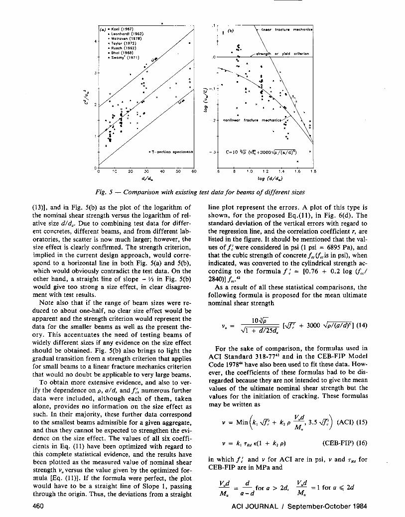
Fig. 5 - Comparison with existing test data for beams of different sizes
(13)], and in Fig. 5(b) as the plot of the logarithm of the nominal shear strength versus the logarithm of relative size dl da. Due to combining test data for different concretes, different beams, and from different laboratories, the scatter is now much larger; however, the size effect is clearly confirmed. The strength criterion, implied in the current design approach, would correspond to a horizontal line in both Fig. 5(a) and 5(b), which would obviously contradict the test data. On the other hand, a straight line of slope - Y2 in Fig. 5(b) would give too strong a size effect, in clear disagreement with test results.
Note also that if the range of beam sizes were reduced to about one-half, no clear size effect would be apparent and the strength criterion would represent the data for the smaller beams as well as the present theory. This accentuates the need of testing beams of widely different sizes if any evidence on the size effect should be obtained. Fig. 5(b) also brings to light the gradual transition from a strength criterion that applies for small beams to a linear fracture mechanics criterion that would no doubt be applicable to very large beams.
To obtain more extensive evidence, and also to verify the dependence on p, aid, and f:, numerous further data were included, although each of them, taken alone, provides no information on the size effect as such. In their majority, these further data correspond to the smallest beams admissible for a given aggregate, and thus they cannot be expected to strengthen the evidence on the size effect. The values of all six coefficients in Eq. (11) have been optimized with regard to this complete statistical evidence, and the results have been plotted as the measured value of nominal shear strength Vu versus the value given by the optimized formula [Eq. (11)]. If the formula were perfect, the plot would have to be a straight line of Slope 1, passing through the origin. Thus, the deviations from a straight
460
line plot represent the errors. A plot of this type is shown, for the proposed Eq.(1l), in Fig. 6(d). The standard deviation of the vertical errors with regard to the regression line, and the correlation coefficient r, are listed in the figure. It should be mentioned that the values of f: were considered in psi (1 psi = 6895 Pa), and that the cubic strength of concrete fcc (fcc is in psi), when indicated, was converted to the cylindrical strength according to the formula f: = [0.76 + 0.2 log (fccl 2840)] f«.42
As a result of all these statistical comparisons, the following formula is proposed for the mean ultimate nominal shear strength
104;> v = [.JT[ + 3000 "';pl(ald)S] (14)
u "';1 + d/25d.
For the sake of comparison, the formulas used in ACI Standard 318-7743 and in the CEB-FIP Model Code 197844 have also been used to fit these data. However, the coefficients of these formulas had to be disregarded because they are not intended to give the mean values of the ultimate nominal shear strength but the values for the initiation of cracking. These formulas may be written as
v = Min (kl .JT: + k z p ~~, 3.5 .JT:) (ACI) (15)
(CEB-FIP) (16)
in which f: and v for ACI are in psi, v and 7Rd for CEB-FIP are in MPa and
d = - for a> 2d,
a-d
Vud - =1 for a ~ 2d Mu
ACI JOURNAL I September-October 1984

3.2 ~-(a-)-A-C-I ----~/~---,--/-,.,.-------,
/ / +>/ / .; /
+i + /,
+.(f /'Y •• 1.+ .... /
+;.<\4~ / + + "'/
/ : +++:! V d / + / V .. =164 ~ +7400 p_u_
3.0
--., 2.8 ,r:.. .S ~ 2.6
-.:. t 2.4
]' 2.2
• / Mu / ~+ &3.5fl.
"tI / •• + .+++/ i 2.0 / .... / ... : ... /
No. of data 296
S.D. = 128 (psi)
=0.549 a : .. :+ j ~ 1.8 t...-L-_L--+--_-+--_-+--_ _+_--+----I
: 3.2 ~-------------r-__:_.....,
I WHU~ ~ f'.I
3.0
~ ~ 2.8
.. 'i 2.6
] S
2.4
] ~
2.2
~
2.0
1.8
V .. =60Vf;pd/a for
V .. =150 Vf;p (d/a)' for
No. of data 296
S.D. = 49.2 (psi) =0.947
(b) CEB-flP +
+ +
+/' ~+ /'
';+4"~
/' /'
/' /'
/'
... .. v .+ /' .. + • /'
y?+...... ...... /' /' ... '" ........... t'" ... ... /'
... ++ t++ /' ... ... ... ... !+ // ~t+ +~*: v .. =13 TRd.:(1+55p) !~+... /
++ ~:t:: / No. of data 296 +,,+ / ++;.: +: /' S.D. = 148 (psi) + /' =0.262
No. of data 296
S.D. = 44.6 (psi) =0.957
1.8 2.0 2.2 2.4 2.6 2.8 3.0 3.2 1.8 2.0 2.2 2.4 2.6 2.8 3.0 3.2
Nominal Ultimate Shear Stress Calculated. log v... (v .. in psi)
Fig, 6 - Comparison of various formulas with the bulk of the existing test data on the ultimate shear strength
TRd 0.01 fck + 0.06 for fCk ~ 20 TRd 0.008 fck + 0.1 for fck > 20 (17)
K = Max( 1. 6 - d, 1) p = Min(A/bd, 0.02) for CEB-FIP
In Eq. (17), d is in meters, but fck in the present form must be given in MPa. Coefficients kl and k2 in these formulas have been optimized to obtain the best fit of all the 377 data points. The resulting optimum fits are shown for the ACI and the CEB-FIP formulas in Fig. 6(a) and (b), and the values of the optimum coefficients are listed for these formulas as well as the present model in Table 1. The scatter apparent from these figures and quantified by the values of standard deviation and the correlation coefficient in these figures is obviously much larger than the scatter for the proposed formula, especially in the case of CEB-FIP formula. It must be kept in mind, however, that these formulas are not intended to give the ultimate strength but the initiation of diagonal shear cracking (as loosely as it may be defined).
The best previous formula is doubtless that of Zsutty,l8 which reads
kl (a/ d)' pi' .t:
q v = (18)
ACI JOURNAL I September-October 1984
Table 1 - Coefficients obtained by nonlinear regression for Vu
Number of available
Model test data k, k, A. p q
ACI318-77 377 1.64 7423 CEB-FIP 377 1.31 54.7
Z tt {a/d~2.5 296 58.4 0.38 0.35 su Y a/d<2.5 81 7829 0.554 -0.0057 Proposed model 296 7.23 3284 25 0.29 0.52
r
0.28 1.50 2.51
in which kl' r, p, and q are four empirical constants. The values of these constants have been optimized again to obtain the best possible fit of the 377 data points used in Fig. 6. The resulting plot is shown in Fig. 6(c). It may be noted that this formula agrees with the data nearly as well as the proposed formula. However, the size effect evidenced in Fig. 5 is not modeled by this formula, although it could be introduced by mUltiplying the formula with the function ct>(A). Note also that, in contrast to the present formula, Zsutty's formula is purely empirical, not based on some mechanics analysis.
As another useful statistic, one may consider the population of the values of Y = (Vtes/veal) - 1, in which Veal is the calculated value and Vtest is the measured value of nominal shear strength. These values are plotted as
461

a function of the logarithm of relative size in Fig. 7. The proposed formula [Fig. 7(d)] appears best. Zsutty's is nearly as good, although it does not reflect the declining trend of the data as a function of dl da, apparent from Fig. 7(c) as well as Fig. 7(d). The scatter for the ACI formula [Fig. 7(a)] is much larger, and even more so for the CEB-FIP formula [Fig. 7(b)]. Despite this larger scatter, a declining trend with regard to the size is noticeable in Fig. 7(a) and (c).
DESIGN PHILOSOPHY: CRACK INITIATION OR FAILURE?
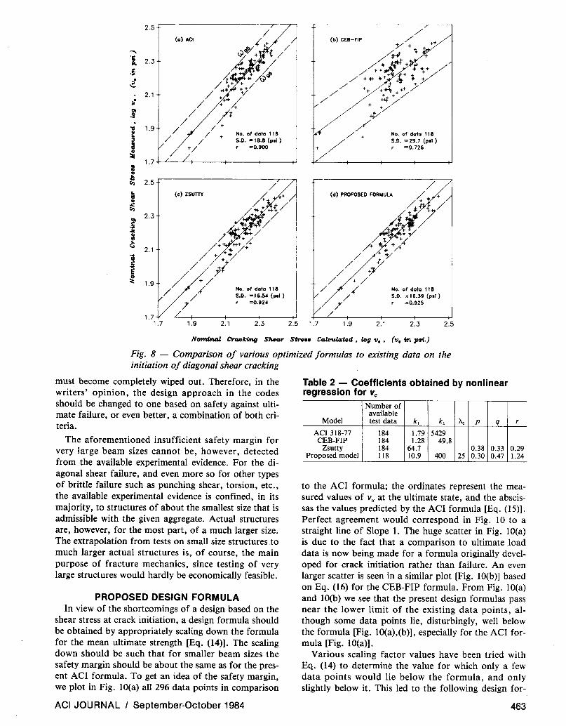
The philosophy of the present design codes is to achieve a certain safety not against the ultimate load in diagonal shear failure but against the load for which the initiation of diagonal shear cracks is observed. Therefore, comparisons have also been made with the (much less numerous) available test data on the nominal cracking shear stress VC. Fig. 8 shows such a comparison in terms of the measured Vc. against the calculated Vc> as obtained by optimizing the coefficients in the formula in Eq. (11), (15), (16), (17), and (18). (Note that all the existing test data for the initiation of diagonal shear cracking are confined to the values of dl da between 10 and 24.) In Fig. 8 the proposed type of formula again gives the best agreement with test data, although only slightly better than Zsutty's formula. The improvement compared to the ACI formula is, in terms of Vc> not very significant, but it is more significant compared to the CEB-FIP formula. The values of the optimized coefficients used in plotting Fig. 8 are listed in Table 2.
.9~~------------------------, (0) ACI
c= 1.64 ~ +7400 P V ud ~ 3.5v'1;;
• Mu .7 .. .5
: '1 · I .3 ~ •
J :~I i1 . 1 ~. , . .' f. , • • f·' :-I·,r: .. :;
-.1 · " . . .. "" ~ . : .
-.:. No. of data 244 ]' -.3 +-----+-----+-----+----+-----+-----l
.4 r--c(;--'c)C"Z:C:S""'U=TTC-Y ---------------------,
.2
. t ~
-.2 C=60 Vf~ pd/a for aid;;; 2.5 •
C=150 Vf~p (d/a)' for a/d<2.5 -.4 +-----+-----+-----+----+-----+----....;
The statistics for the nominal cracking shear stress Vc
may also be worked out for the variable Y = (Vtes/Vcal)
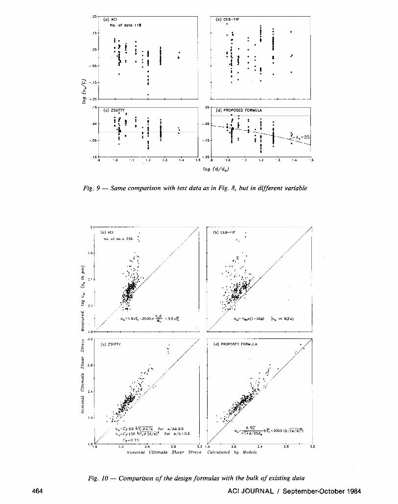
- 1. These values are plotted for all the four formulas against the logarithm of the relative size dlda in Fig. 9. It is apparent that, for crack initiation, the size effect is much less pronounced, nearly undetectable. In fact, for the true crack initation, the size effect should be nonexistent, since the beams do not contain any initial stress concentrator (a notch). The fact that any size effect seems to be apparent indicates that the observed values of Vc did not in fact correspond to the true crack initiation, which, of course, is very difficult to define as the cracking begins by a gradual formation of invisible microcracks.
The fact that no significant size effect on the nominal shear stress at cracking is observed while at the same time the size effect is clearly confirmed by tests of the ultimate nominal shear strength raises a question with regard to the present design philosophy of designing against crack initiation rather than ultimate failure. Since the ultimate value of p decreases with size, there obviously exists a certain sufficiently large size for which the ultimate p ceases to be larger than the value of p for crack initiation. This is, of course, natural to expect. It is known from nonlinear fracture mechanics that the strength reserve due to stable crack growth becomes smaller as the size increases and vanishes when a certain size is exceeded.
Thus, designing against the crack initiation rather than ultimate failure does not assure a uniform safety margin. The safety margin decreases with increasing dlda, and for a sufficiently large dlda the safety margin
(b) CEB-FIP
C= 1.3 TRdX:( l-t.55p) ..
:
•
. .
(d) PROPOSED FORMULA
.6 .8 f.O f.2 f.4 f.6 f.8.6 .8 1.0 1.2 1.4 1.6 1.8
log (d/d.)
Fig. 7 - Same data as in Fig. 6 compared with formulas in a different manner
462 ACI JOURNAL I September-October 1984
2.5
..... 'Ii ~ 2.3
. -=-
- 2.1
(a) ACI
No. of data 11 8 S.D. "'18.8 (pil )
=0.900
1.7 .j.......<~-.L..-+-__ -+ ___ f--__ +'
.5 2.3
~
l 2.1
1.9
(c) zsum
1.9 2.1
No. of dolo 118 S.D. = 16.54 (pil )
=0.124
2.3 2.5 1.7
(b) CEB-FIP
No. of dala 118 S.D. =29.7 (pll)
=0.726
(d) PROPOSED FORMULA
1.9 2.1
No. of dolo 118 S.D. = 16.39 (pil )
=0.925
2.3 2.5
Nomi"'" Orc&ok-£ng SMa.r Str... Ca.lct.da.ted. log 1).. (1). in pai.)
Fig. 8 - Comparison of various optimized formulas to existing data on the initiation of diagonal shear cracking
must become completely wiped out. Therefore, in the writers' opinion, the design approach in the codes should be changed to one based on safety against ultimate failure, or even better, a combination of both criteria.
The aforementioned insufficient safety margin for very large beam sizes cannot be, however, detected from the available experimental evidence. For the diagonal shear failure, and even more so for other types of brittle failure such as punching shear, torsion, etc., the available experimental evidence is confined, in its majority, to structures of about the smallest size that is admissible with the given aggregate. Actual structures are, however, for the most part, of a much larger size. The extrapolation from tests on small size structures to much larger actual structures is, of course, the main purpose of fracture mechanics, since testing of very large structures would hardly be economically feasible.
PROPOSED DESIGN FORMULA In view of the shortcomings of a design based on the
shear stress at crack initiation, a design formula should be obtained by appropriately scaling down the formula for the mean ultimate strength [Eq. (14)]. The scaling down should be such that for smaller beam sizes the safety margin should be about the same as for the present ACI formula. To get an idea of the safety margin, we plot in Fig. lO(a) all 296 data points in comparison
ACI JOURNAL I September-October 1984
Table 2 - Coefficients obtained by nonlinear regression for Vc
Number of available
Model test data k, k, Ao p q
ACI318-77 184 1.79 5429 CEB-FIP 184 1.28 49.8
Zsutty 184 64.7 0.38 0.33 Proposed model 118 10.9 400 25 0.30 0.47
r
0.29 1.24
to the ACI formula; the ordinates represent the measured values of Vu at the ultimate state, and the abscissas the values predicted by the ACI formula [Eq. (15)]. Perfect agreement would correspond in Fig. 10 to a straight line of Slope 1. The huge scatter in Fig. lO(a) is due to the fact that a comparison to ultimate load data is now being made for a formula originally developed for crack initiation rather than failure. An even larger scatter is seen in a similar plot [Fig. lO(b)] based on Eq. (16) for the CEB-FIP formula. From Fig. lO(a) and lO(b) we see that the present design formulas pass near the lower limit of the existing data points, although some data points lie, disturbingly, well below the formula [Fig. lO(a),(b»). especially for the ACI formula [Fig. lO(a)].
Various scaling factor values have been tried with Eq. (14) to determine the value for which only a few data points would lie below the formula, and only slightly below it. This led to the following design for-
463
464
'""'
.25r-c-(O-,)-A-C-I-----------------.
.15
.05
-.05
No. of dolo 118
! . ., i ·.i . i
I
(b) CEB-tlP
· • • .. ; • • .. .
.1 l · • • ~ -.15
-.:.. S -.25 +---+---!------;e----4----+--~
.15 r-7(C"""')-,Z::S""U=T=n-,-------------------,
. 05
-.05
• S
i! f • ·L • I
i : • i
. i . .
.05 r-7( dc-;)-P::R=-=O:-::P:-::O-=S::-EO=--=,COO::-R:-:M:-:ULA:-::-:------------,
I' * -.051-_ •• r •
1----- .. · . . - t . -.15 :; r ---1::~25
t. '---• • -.1 5 +---+---!----e-----;----4--~ -.25 +---+---+--->----e-----;-----4
.9 1.0 1.1 1.2 1.3 1.4 1.5 .9 1.0 1.1 1.2 1.4 1.5
log (d/d.)
Fig. 9 - Same comparison with test data as in Fig. 8, but in different variable
.~
'" ~ $ • ~
;.
" '" -'l
1:i ~ ~ ;l
'" t:l ~
~
'" '" ~ .t V]
~ ~
"'" V]
~
"'il ~ S
"il .~ ~ 0 :;,;
2.8
2.4
2.0
1.6
3.2
2.8
2.4
2.0
(0) ACI
No. of data 296 ++
(e) ZSUTTY
, ....... -: *+ +
++:t ....
.... + :",,++ :1.+ • .:
,:..i1'-:;: ;$r
: -i":}: / 1Ju~CF'60 'If; pd/a for a/d~ 2.5
/ 1Ju~CF'150 'l./f,p (d/a)' for a/d<2.5
CF~O.75
(b) CEB-FlP
" , ' ".." ~
(d) PROPOSED FORMULA
. , ( t;
v. ~ (Vf;+3000Yp/(a/d)") l+d 25d.
1.61;C.6----;~-2~.0:---+--~2.-4-~----:2+:.8----;~----::<3.2 1.6 2.0 2.4 2.8
Nominal Ultimate Shear Stress Calculated by Models
Fig. 10 - Comparison of the design formulas with the bulk of existing data
3.2
ACI JOURNAL I September-October 1984

mula, which is proposed here as a replacement for the present code formulation of ACI or CEB-FIP
v 8* (fJ'1 + 3000 ~) ~
d VIc ~ a 5 '
1 + --25da
Vud with a = (19)
Mu
Here a = a/ d for the case of concentrated load (Fig. 2), and a = fl4d for that of uniform load (heref:must be in psi). This formula is shown by the straight line in Fig. lO(d). Unlike Fig. 10(a), no data points fall signif
,icantly below this formula. Note that the band of data points based on this formula becomes much narrower than for the present code formulations [Fig. lO(a),(b)] and is also somewhat narrower than for Zsutty's formula shown in Fig. lO(c). This formula was also scaled (replacing kl in Eq. (18) by ko = 0.75kl) so that only a few data points would lie below the formula.
The fact that no data points in Fig. lO(d) for the present formulation lie high above the straight inclined line means that the proposed formula is overall economic. The economy may be quantitatively characterized by factor cf>. = E; tJ./ny where y = ordinate of data centroid, tJ.; = vertical deviation of data points from the straight line (i = 1,2, ... n), and n = number of all points. Only the points lying above the straight line are counted. The smaller is cf> .. the better the economy. Calculations yield cf>. = 0.595, 0.844, 0.448, and 0.290 for Fig. lO(a), (b), (c), and (d), respectively. The num-
,6
.. : , . .
~ t .2 ~ • t
8. :'1. :t .. J L '""" 0';0 • 0
$ ~
~ 0,0 . .
o .-! .. . ;>
,. '- ..
'I . 0) . .s -.2
.5 (e) ZSUTTY
" . .3
... : i I 0
I.. .. r . . .: .~. I .. 1~ !~ • .1
f.· I 00 0 •
C,=O.75 , ~ .
-.1 a/d<2.5 C=C,150 Vf~p (d/a)' for
C=C"60 ~Pd/a for a/d~2.5 -.3 +----+---+-----i--+---+------"
bers of points that lie above the inclined straight line are n = 249, 289, 286, and 286, respectively.
Fig. 11 shows the same comparisons as Fig. 10, but in different variables. The ordinates are, similarly to Fig. 9, the values of Y = (Vtes/Vcal) - 1. The comparisons lead to similar conclusions as Fig. 10. (Note that only 25 data points of the 77 data points of Kani 13 are plotted in Fig. 7 and 11, although all data points agree with the formula well; this is because they all refer to the same beam size and are all crowded in such a small spot that they could not be graphically distinguished.) From Fig. l1(a) we see that the points laying significantly below the ACI formula correspond indeed to large beam sizes, which again confirms our previous argument about the size effect and how it affects the safety margin.
REMARK ON THE EFFECT OF SHEAR REINFORCEMENT
It is certainly a reasonable design approach to assume, as is done in current codes, that the ultimate load in presence of shear reinforcement (stirrups) is a sum of the ultimate load in absence of the shear reinforcement plus the additional capacity due to the shear reinforcement alone, obtained by plastic analysis. This approach, however, is not as easy as it might seem, since the presence of shear reinforcement mitigates the size effect, as shown in Reference 34 by a similar dimensional analysis. No meaningful experimental evidence seems to be available for the size effect in presence of shear reinforcement. It is, nevertheless, theoretically evident that the reduction in the loss of safety margin
(b) CEB-FIP
(d) PROPOSED FORMULA
. .
.6 .8 1.0 1.2 1.4 1.6 1.8.6 .8 1.0 1.2 1.< 1.6 1.8
log (d/d.)
Fig. 11 - Same comparison as in Fig. 10, plotted in a different variable
ACI JOURNAL I September-October 1984 465

with the increasing size, which has been demonstrated here for the presently used strength-based formulas for the cracking nominal shear strength, may be considerably milder or even insignificant when shear reinforcement is present. This question is of great interest for very large structures and calls for further investigation.
IMPLICATIONS FOR PLASTICITY ANALYSIS Recently, in an effort to replace purely empirical de
sign formulas by some rational mechanics analysis, it has become popular to apply plastic limit analysis not only to ductile failures of concrete structures due to yielding of reinforcement but also to brittle failures due to failure of concrete. The results of the present study shed further doubts on this approach. Plasticity yields an incorrect size effect for the brittle shear failure of beams and is likely to do the same for other brittle failures such as torsion of beams or punching shear of slabs. This is, of course, not surprising since the stress-strain relation of concrete has no yield plateau and exhibits strain softening, which causes that the limit stress state cannot exist simultaneously along some postulated failure surface, as required by plastic limit analysis, but is reached successively at various points of the failure surface.
In some recent investigations it was concluded that plastic limit analysis "works" for punching shear failures of slabs. However, to make it "work," the tensile strength had to be considered to be 11200 of the compressive strength. This is about 20-times less than the actual tensile strength. How can it be so low? A likely explanation is the fracture mechanics size effect, and if this is so it means that plastic limit analysis does not work. Various apparent successes of plastic limit analysis of brittle failures of concrete structures, recently presented in the literature, are likely due to the fact that really large structures have never been tested and the size effect has never been checked.
With the exception of conditions of very high hydrostatic pressure and of structures that fail primarily due to yielding of reinforcement, plasticity is not the correct theory for concrete. Fracture mechanics, of the proper type, is.
IMPLICATIONS FOR FINITE ELEMENT ANALYSIS OF CRACKING
Finite element analysis based on the strength criterion does not yield any size effect, i.e., it corresponds to a horizontal line in Fig. 1 or 5(b) when failure loads for geometrically similar structures, obtained with similar meshes, are compared. The fact that the experimental results in Fig. 5(b) disagree with the horizontal line means that this type of finite element analysis cannot be used for what is its main purpose, that is, to predict the failure of a real size structure after calibrating the finite element code by means of laboratory-size tests. Therefore, fracture mechanics-type cracking criteria must be used for this purpose in finite element codes. Not, of course, linear elastic fracture mechan-
466
ics, because such finite element anlaysis would give the size effect according to the straight line of downward slope - Y2 in Fig. 1 or 5(b), but nonlinear fracture mechanics. A finite element model of this type, which is suitable for large-scale computation and leads to the curved transition diagram shown in Fig. 1 or 5(b), has been presented in References 35 and 33.
CONCLUSIONS 1. For diagonal shear failure of reinforced beams and
one-way slabs without shear reinforcement, it is appropriate to consider the size effect which theoretically results from a dimensional analysis of the energy release rate in the propagation of fractures that have a dispersed cracking zone at their front.
2. A size effect of this type agrees with available test data far better than either the lack of size effect corresponding to the strength criterion or the size effect of linear elastic fracture mechanics.
3. As a function of the ratio of beam depth d to maximum aggregate size da, the nominal shear strength exhibits a gradual transition from the strength criterion (which prevails for dlda < 25) to an energy criterion for fracture (which prevails for dlda > 25). For extremely large beam depths, the size effect of linear elastic fracture mechanics is approached asymptotically. Most of the existing test data are confined to the range for which the strength criterion dominates.
4. The present practice of designing against the initiation of diagonal shear cracks rather than ultimate failure does not yield a uniform safety margin when different beam sizes are considered, and the safety margin becomes completely wiped out for a sufficiently large size. From the viewpoint of the size effect, only a design formula based on the ultimate failure load [Eq. (19)] can provide a uniform safety margin against catastrophic failure for all structure sizes.
5. A rational, mechanics-based formula for the effect of steel ratio and relative shear span can be obtained by superimposing the shear forces transmitted by composite beam action and by arch action. This yields a formula which is similar to that presently used in ACI code but is in better agreement with test data.
ACKNOWLEDGMENT Some of the theoretical fracture studies relevant to the present work
have been supported by the National Science Foundation under Grant No. CEE-8303148 to Northwestern University. Thanks are due to Mary Hill for her invaluable secretarial assistance.
REFERENCES 1. ACI-ASCE Committee 326, "Shear and Diagonal Tension, Parts
1 and 2," ACI JOURNAL, Proceedings V. 59, No. I, Jan. 1962, pp. 1-30, and No.2, Feb. 1962, pp. 277-334.
2. "Shear, Torsion and Punching," Bulletin d'Information No. 146, Comite Euro-International du Beton, Paris, Jan. 1982,225 pp.
3. Fenwick, R. C., and Paulay, Thomas, "Mechanics of Shear Resistance of Concrete Beams," Proceedings, ASCE, V. 94, STIO, Oct. 1968, pp. 2325-2350.
4. Hedman, 0., and Losberg, A., "Structural Design of Concrete Construction Based on Shear Failure," Nordisk Betong (Stockholm), No.5, 1975, pp. 19-29. (in Swedish)
ACI JOURNAL I September-October 1984

5. Kani, G. N. J., "The Riddle of Shear Failure and Its Solution," ACI JOURNAL, Proceedings V. 61, No.4, Apr. 1964, pp. 441-467.
6. MacGregor, J. G., and Gergely, P., "Suggested Revisions to ACI Building Code Clauses Dealing with Shear in Beams," ACI JOURNAL, Proceedings V. 74, No. 10, Oct. 1977, pp. 493-500.
7. Reinhardt, H. W., "Masstabseinfluss bei Schubversuchen im Licht der Bruchmechanik," Beton- und Stahlbetonbau (Berlin), No. I, 1981, pp. 19-21.
8. Taylor, Howard P. J., "The Shear Strength of Large Beams," Proceedings, ASCE, V. 98, STll, Nov. 1972, pp. 2473-2490.
9. Bhal, N.S., "Uber den Einfluss der Balkenhohe auf Schubtragfahigkeit von einfeldrigen Stahl beton balk en mit und ohne Schubbewehrung," dissertation, Universitiit Stuttgart, 1968, 124 pp.
10. Bresler, Boris, and Scordelis, A.C., "Shear Strength of Reinforced Concrete Beams," ACI JOURNAL, Proceedings V. 60, No. I, Jan. 1963, pp. 51-54.
11. Forssell, C., "Tests of Shear Strength and Shear Reinforcement of Concrete Beams (Schubfestigkeit und Schubbewehrung der Betonbalken)," Handlingar No. 78, Kungliga Tekniska Hogskolans, Stockholm, 1954, pp. 31-32.
12. Kani, G. N. J., "Basic Facts Concerning Shear Failure," ACI JOURNAL, Proceedings V. 63, No.6, June 1966, pp. 675-692.
13. Kani, G. N. J., "How Safe Are Our Large Reinforced Concrete Beams?," ACI JOURNAL, Proceedings V. 64, No.3, Mar. 1967, pp. 128-141.
14. Koch, R., and Rostasy, F. S., "Schubtragfahigkeit von Platten aus Stahlleichtbeton ohne Schubbewehrung," Beton- und Stahlbetonbau (Berlin), V. 73, 1978, pp. 42-46.
15. Krefeld, William J., and Thurston, Charles W., "Studies of the Shear and Diagonal Tension Strength of Simply Supported Reinforced Concrete Beams," ACI JOURNAL, Proceedings V. 63, No.4, Apr. 1966, pp. 451-476.
16. Leonhardt, F., and Walther, R., "Beitrage zur Behandlung der Schubprobleme im Stahlbetonbau," Beton- und Stahlbetonbau (Berlin), V. 56, No. 12, 1961; V. 57, No.2, 3, 6, 7,8, 1962; and V. 58, No.8 and 9, 1963.
17. Mathey, Robert G., and Watstein, David, "Shear Strength of Beams Without Web Reinforcement," ACI JOURNAL, Proceedings V. 60, No.2, Feb. 1963, pp. 183-208.
18. Mattock, Alan H., "Diagonal Tension Cracking in Concrete Beams with Axial Forces," Proceedings, ASCE, V. 95, ST9, Sept. 1969, pp. 1887-1900.
19. Moody, K. G.; Viest, I. M.; Eistner, R. c.; and Hognestad, E., "Shear Strength of Reinforced Concrete Beams, Parts I and 2," ACI JOURNAL, Proceedings V. 51, No.4, Dec. 1954, pp. 317-332, and No. 5, Jan. 1955, pp. 417-436.
20. Ojha, S. K., "The Shear Strength of Uniformly Loaded Beams Without Web Reinforcement," Magazine of Concrete Research (London), V. 23, No. 75, June 1971, pp. lll-ll8.
21. Placas, Alexander, and Regan, Paul E., "Shear Failure of Reinforced Concrete Beams," ACI JOURNAL, Proceedings V. 68, No. 10, Oct. 1971, pp. 763-773.
22. Rajagopalan, K. S., and Ferguson, Phil M., "Exploratory Shear Tests Emphasizing Percentage of Longitudinal Steel," ACI JOURNAL, Proceedings V. 65, No.8, Aug. 1968, pp. 634-638.
23. Diaz de Cossio, Roger, and Siess, Chester P., "Behavior and Strength in Shear of Beams and Frames Without Web Reinforcement," ACI JOURNAL, Proceedings V. 56, No.8, Feb. 1960, pp. 695-735.
24. Rusch, Hubert; Haugli, Finn Robert; and Mayer, Horst, "Schubversuche an Stahlbeton-Rechteckbalken mit gleichmiissig verteilter Belastung," Bulletin No. 145, Deutscher Ausschuss fUr Stahlbeton, Berlin, 1962, pp. 4-30.
25. Swamy, R. Narayan, and Qureshi, Shamsuddin A., "Strength, Cracking, and Deformation Similitude in Reinforced T-Beams Under Bending and Shear," ACI JOURNAL, Proceedings V. 68, No.3, Mar. 1971, pp. 187-195. .
26. Taylor, R., "Some Shear Tests on Reinforced Concrete Beams Without Shear Reinforcement," Magazine of Concrete Research (London), V. 12, No. 36, Nov. 1960, pp. 145-154.
27. Van den Berg, F. J., "Shear Strength of Reinforced Concrete Beams Without Web Reinforcement. Pan 2-Factors Affecting Load
ACI JOURNAL I September-October 1984
at Diagonal Cracking," ACI JOURNAL, Proceedings V. 59, No. ll, Nov. 1962, pp. 1587-1600.
28. Walraven, J. C., "The Influence of Depth on the Shear Strength of Lightweight Concrete Beams Without Shear Reinforcement," Stevin Laboratory Report No. 5-78-4, Delft University of Technology, 1978, 36 pp.
29. Park, Robert, and Paulay, Thomas, Reinforced Concrete Structures, John Wiley & Sons, New York, 1975,769 pp.
30. BaZant, Zdenek P., and Cedolin, Luigi, "Fracture Mechanics of Reinforced Concrete," Proceedings, ASCE, V. 106, EM6, Dec. 1980, pp. 1287-1306.
31. BaZant, Zdenek P., and Cedolin, Luigi, "Finite Element Modeling of Crack Band Propagation," Journal oj Structural Engineering, ASCE, V. 109, No. I, Jan. 1983, pp. 69-92.
32. Reinhardt, H. W., "Similitude of Brittle Fracture of Structural Concrete," Advanced Mechanics of Reinforced Concrete, IABSE Colloquium, Delft, 1981, pp. 201-210.
33. BaZant, Z. P., "Crack Band Model for Fracture of Geomaterials," Proceedings, 4th International Conference on Numerical Methods in Geomechanics, University of Alberta, Edmonton, 1982, V. 3, pp. 1I37-1I52.
34. BaZant, Z. P., "Mechanics of Fracture and Progressive Cracking in Concrete Structures," Report No. 83-21428m, Center for Concrete and Geomaterials, Northwestern University, Evanston, Feb. 1983, 130 pp. Also, to appear in Fracture Mechanics Applied to Concrete Structures, Martinus Nijhoff Publishers, The Hague.
35. Bazant, Zdenek P., and Oh, B. H., "Crack Band Theory for Fracture of Concrete," Materials and Structures, Research and Testing (RILEM, Paris), V. 16, No. 93, May-June 1983, pp. 155-177.
36. Knott, J. F., Fundamentals of Fracture Mechanics, Butterworth & Co. (Publishers) Ltd., London, 1973, 273 pp.
37. Bazant, Z. P., "Size Effect in Blunt Fracture: Concrete, Rock, Metal," Report No. 83-2/665s, Center for Concrete and Geomaterials, Northwestern University, Evanston, Feb. 1983, 24 pp. Also, to appear in Journal of Structural Engineering, ASCE, V. 1I0, No. EM4, Apr. 1984, pp. 518-535.
38. Zsutty, Theodore C., "Beam Shear Strength Prediction by Analysis of Existing Data," ACI JOURNAL, Proceedings V. 65, No. ll, Nov. 1968, pp. 943-951.
39. Zsutty, Theodore, "Shear Strength Prediction for Separate Categories of Simple Beam Tests," ACI JOURNAL, Proceedings V. 68, No.2, Feb. 1971, pp. 138-143.
40. Marquardt, D. W., "An Algorithm for Least-Squares Estimation of Nonlinear Parameters," Journal, SIAM, V. ll, No.2, 1963, pp. 431-441.
41. Brown, K. M., and Dennis, 1. E., "Derivative Free Analogues of the Levenberg-Marquardt and Gauss Algorithms for Nonlinear Least Squares Approximations," Numerische Mathematik No. 18, 1972, pp. 289-297.
42. Neville, Adam M., "A General Relation for Strengths of Concrete Specimens of Different Shapes and Sizes," ACI JOURNAL, Proceedings V. 63, No. 10, Oct. 1966, pp. 1095-1I09.
43. ACI Committee 318, "Building Code Requirements for Reinforced Concrete (ACI 318-77)," American Concrete Institute, Detroit, 1977, 102 pp.
44. CEB-FIP Model Code for Concrete Structures, 3rd Edition, Comite Euro-International du Beton/Federation Internationale de la Precontrainte, Paris (English Edition, Cement and Concrete Association, Wexham Springs), 1978, 348 pp.
APPENDIX For readers' convenience we summarize the dimensional analysis
from Reference 37 that leads to Eq. (I). To take the dispersed and progressive nature of cracking at the fracture front into account, the following hypothesis may be introduced: The total potential energy release W caused by fracture in a given structure is a function of both (I) the length of the fracture a, and (2) the area of the cracked zone amda•
Here m = material constant characterizing the width of the cracking zone at the fracture front." Under Part (I) of the hypothesis we understand the part of energy that is released from the uncracked regions of the structures into the fracture front.
467

Variables a and amda are not nondimensional. They are, however, allowed to appear only in a nondimensional form. This form is given by the following variables
a
d
amda
d' (20)
representing the nondimensional fracture length and the nondimensional area of the cracked zone. Furthermore, W must be proportional to volume d' b of the structure (where b = thickness) and to the characteristic energy density uV2£, in which UN = P/bd = nominal stress at failure, P = given applied load, and d = characteristic dimension of the structures. Consequently, we must have
1 (P)' W = - - bd'f(cx" a" ~;) 2£, bd
(21)
in which f is a certain continuous and continuously differentiable positive function, and parameters t represent ratios of the structure dimensions characterizing the geometrical shape of the structure. For similar structures, ~; are constant. The condition for the fracture to propagate is
oW
oa = Gfb (22)
in which Gf is the fracture energy, a material property characterizing the energy consumed per unit extension of the fracture, per unit thickness.
468
Consider now geometrically similar structures, for which parameter ~; are constant and only the characteristic dimension d varies. According to the chain rule of differentiation, of/oa = f, (oa/oa) + I, (ocx,/oa), in which we introduce the notationf, =' of/oa"I, = of/oa,. Thus, substitution of Eq. (21) into Eq. (22) yields
-+-- --=Gb (
I, I, mda) P' d d' 2bE, f
(23)
Furthermore, the fracture energy may be expressed as the area under the complete tensile stress-strain curve, including the strain softening down to zero stress, times the width of the cracking front mda"
mda
(1 _ E') f:' E, 2£,
(24)
in which E, is the initial elastic modulus of concrete, E, is the mean strain-softening modulus, which is negative, and f: is the dir,ect tensile strength of concrete. Substituting Eq. (24) and P = UN bd into Eq. (23), we may obtain"
U = BI" 1 + -( d) -tl,
N 'J, }...Pa (25)
in which B = [(1 - E,IE,)/f,)'12 and -,...., = mI,/f,. Band -,.... are constants when geometrically similar structures of different sizes are considered. Thus, Eq. (25) proves our starting equation, Eq. (1).
ACI JOURNAL I September-October 1984


![Shear Capacity of Steel Fiber Non-Metallic (GFRP) Reinforced … · 2020. 8. 4. · Noor Azline et al. ,2013 .[15] , presents test results of beams longitudinally reinforced either](https://img.dokumen.tips/doc/110x75/611f33e9002f6f39fe08dad4/shear-capacity-of-steel-fiber-non-metallic-gfrp-reinforced-2020-8-4-noor.jpg)