Embed Size (px)
Citation preview
ACI STRUCTURAL JOURNAL TECHNICAL PAPER Title no. 84'S6
Size Effect in Punching Shear Failure of Slabs
by Zdenek P. BaUlnt and Zhiping Cao
Po"""", _ ,.." <>J _riMI1 # .. 110< m,vt>lC'<d ~_ Q/ ~ " ... __ ... ,. 11w __ """,,,~,,
i< _ '-"",. __ .. 1M """'" «>ir~ /_d ... "", d<"""" '" IM"'~ .h. ,~. ~ _ "" .u"'" ,. """".I", 'MI" ,,, .. ,,,/0 ~ oP"''''''''"'fi)' /ks<tib<d by on ""proowl Msi,. 1",,,,." ,../Oklo ..... 1M ';«-<11«:1 /<ow /'" bri,,1r /.il.,.. dll< I. d;'· ";j,,,lfti < .... ~; ... , "ppI~;r '" liolt low it i""/oH ",_1«1 bf A .,,~"" '" dtJIt<t_.,..,...,.,. _ 1<WOI, .... ,It< _-",," ___ .... _ .. ,,,,_si:<_._fGf .t. by ... _ ..... , .... ''''' "'" _ .Mlr.<d _ior/T a "'" .. ~ . " . Dw ro ,.,. --"~y '" "'"'" • ..;,/0," ,lois S<I. 1M ~ 0/ """"fi_ ",..1/.",)'."<1 "t, I«k oj ",.!f>con,'r dl//""" ,I.b ,i= ,..UM. "'" ,;",1< , .. ' _. ,/tnt ~iq", .. " "",. ".;,!ot< «>1-
m!><>T." " Of <o.,,..!,,,, ''''' opplk"bil"J' "f In. .i'~!«1 I." 10 P'''''Im>r'-.
""_= __ ..... : " ....... ",,,,,_I: --..;'''' •• ;0. .. , _ ...,., ,,",,,,, •. _,,,"",,",,, _: , ..... MOSI current d.sign formulas for failur e loads of
concrele $lructurcs are based On plastic limit anal)'$Ls. Theorctically, plastic limit analysis is justified only if the lo..d-deOmion diagram ,mnina,« wilh a 10", horizontal yield plateau. Durin, the 1970'" il ne.cnhtl«s became »Qpular 10 apply limit analy,is 10 all types of failure, includinR vari ous briul. failures, su~h as Ih. punching shear failure. R«:enlly Ihi' trend has been recognized to be unjustified, 8ril1l. failures of O:OnCrete struclur .. , .. 'hich are chara<:l.riud b)' a gradual declin. of load II Increasing den.ction afler th. peak ,,, ... poinl, cannOt be adequatd)' de5Cribed by pla,tic limit analyoi. because the failure does n01 OCcur simultane' ously alon, the ultimate failu" lurra~ (e~~ for very $lIUl1 slfuClur«). Rllhn. the fail"'" is p'o,'mi"e, i.e" the failu .. ~on. proPlJiate:s acr .... lbe mucture. "'ilh the .ner~y dissipation localized into the crackin, fronL Thus, Ihe failure load Should be predi<1ed by fracture mechanic>, • theory which is based on enerllY and lIa· bilit}' criteria inllead of men/llh crite,i • . Ho",(:\'.r, the classical. lin.;u .wtic fraClure """h.aoies is normall)' inappl;a,ble because the fraeture front is n01 sharp but blunted by distributed crackin/l.···
The salitnt lUpeet of f •• eture mechani« is lhe size eff",!. Wh.reas for plastic li mit analysis ias wtll as for
"
the .llStic allowabl. 51rm design) the nominal men at failur. of teometrically ,imiJar mu<1u'« is sil('·inde· pendenl, for fraeture mecha~;c. it decreases as the SlruCture size increases. The clanic~l , linea r elastic fracture mechanics yidd. the .trongosl possihle size cr· fm. which is found 10 be excessive rOT moSt conCrete. struaures, A new nonlin"'r form of flaou.e n>«bania. approximately forrnula(ed as the blunt crack band mod.l, yields a milder size effect, for which a ,impl • size .. ffm law waS derived by dimensional analy,is and siml1irude arguments, ' Thi, ,iu·effm law was ,bown (0 lJI'tt .. "",nably wen wilh Ibe ICSI dati from "arious types of fraClure specirnm",
In ,b. Curr.nt desi,n codes. Ihe formula, for th. brin l. failu res of concrete Slructure, ignore fr acture mechanics and e~hibi t no ,ize effm, Howe.er , in 11,. preceding .Iudi.s of diagonal .hear failure of uttp,.· st,eued and p'CllrO$sed beam. wilhoul .tirrnp.Y of rinl and beam failurC$ of unreinfOTCflI pipe1.· .."d of touion failure of plain Or 10n&itudinally 'cinloretd beams, ' it has b«n found that tbe Ivailable test data .xhibit a size effect dc~rihable by Ihe . ize-effec1 law for blunt fraclu,e, This corroborat •• th. initial Iheor.t· ieal prol>O'ilion lhaltl>c: size .. ffec11aw sl>ould apply, in an approximate sense, 10 alilh. bril1!c failnr« of <On>
crete flTUClnres, Th. present s,udy IlIcmpto 10 examine lhit propo.ition for the case of PIlnthin, shear .
REVIEW OF SIZE,EFFECT LAW Co ... ider zeometrically similar cOOCrete strUCIU.C$ of
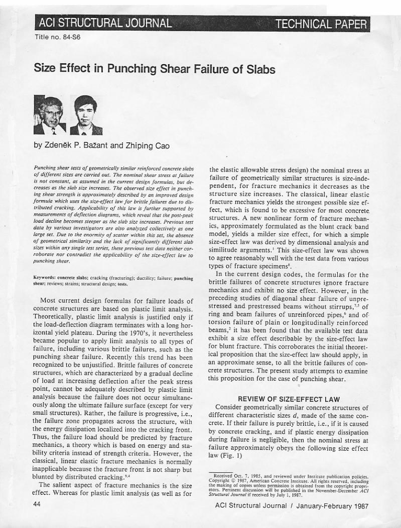
differen, charaClcriRk siz« d, made of tl>c: same concrete, If tbtir failure is PIlrely brinle, i. ... if it i. Clused b}' COnCrete crackin~, and if plastk ener/lY dissipation durin~ failure is negligible, thcn Ih. nominal strell at failure appro~imat.ly obe)'. the fOllowing size eff.ct la",' (Fig. l)
ACI Structural Journal I January·February t987
Zdmlk P. Bat-ant, FA CI, is a professor and director, Center for ConCTl!te and Geomaterials, Northwestern University. Dr. Batont is a registered structural engineer, serves as consultant to Argonne Notional Laboratory and several other firms, and is on editorial boards 0/ five journals. He is Chairman 0/ A CI Commillee 446, Fracture Mechanics, and a member of ACI Commillee 209, Creep and Shrinkage in Concrete; 348, Structural Safety; and joint ACI·ASCE Commillee 334, Concrete Shell Design and Construction. He also serves as Chairman 0/ RILEM Committee TC69 on creep, 0/ ASCE·EMD Committee on Properties of Materials, and of IA-SMiRT Division H. His works on concrete and geomaterials, inelastic behavior,/racture and stability have been recognized by a RILEM medal, ASCE Huber Prize and T. Y. Lin A word, IR-IOO A ward, Guggenheim Fellowship, Ford Foundation Fellowship, and election as Fellow of American Academy 0/ Mechanics.
Zhiping Cao is a senior civil engineer and director, Center for Building Design, DeSign Institute, Yellow River Conservancy Commission, Zhengzhou, Henan Province, People's Republic 0/ Chino. He has token port in the planning 0/ Yellow River Volley and several large hydraulic engineering projects. Mr. Coo spent the lost two years as Visiting Scholar at the Center lor Concrete and Geomateria/s of Northwestern University, conducting both theoretical and experimental researches on the fracture mechanics applications and size effect in the failure 0/ prestressed concrete beams, reinforced slobs, and pipes.
aN == Bf,' ¢ (A), ¢ (A) (1)
where aN == Plbd where P = load at failure and b = thickness' of structure; 1,' == direct tensile strength of concrete, do '== maximum aggregate size, A = dido = relative structure size; and B, >-0 = empirical parameters characterizing the fracture energy of the material and the shape of the structure. This formula, which was derived by dimensional analysis and similitude arguments,' represents a gradual transition from the failure criterion of limit analysis (or allowable stress design) to the linear elastic fracture mechanics. The case of limit analysis, corresponding to a horizontal strength line in Fig. I, is obtained for very small structures (A .erg Mo), and the case of linear elastic fracture mechanics, corresponding to a straight line of slope - Yz, is obtained for very large structures (A ~ Aodo). Most practical structures represent the intermediate case, whereas most available laboratory data are near the limit analysis case (A .erg Mo).
The size-effect law was found to be in approximate agreement with the results of fracture tests of concrete. Furthermore, the test data available in the literature for diagonal shear failure of longitudinally reinforced nonprestressed as well as prestressed beams, for torsion failure of beams, and for beam and ring failures of pipes, were found to be in acceptable agreement',s.6·2
'
with the size-effect law although they could not be said to validate it, due to the large random scatter of the data.
Recently, it has been shown (see References 3 and 4 and the closure to Reference 7) that Eq. (1) represents the first order approximation to the most general sizeeffect law which reads aN == B 1,' (~-' + 1 + c,~ + c2e + C3~3 + . . .}112' where ~ = (A/Mo)'; 1,' , B, >-0, r, C,' C2' ••• == constants. Furthermore, when do varies, 1,' varies, too, and approximately f: ==!? [1 + (Col do}'/2], where!?, Co == constants. However, these refinements of Eq. (1) are not used in the present' study since they introduce further unknown parameters, the deter-
ACI Structural Journal I January-February 1987
mination of which is impossible because of the high random scatter of the existing test data.
TEST SPECIMENS To check the size effect, a series of tests of micro
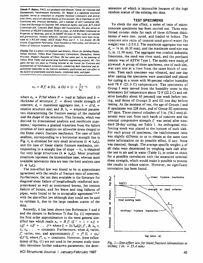
concrete specimens has been carried out. Three reinforced circular slabs for each of three different thicknesses d were cast, cured, and loaded to failure. The concrete mix ratio of cement:sand:gravel:water (by weight) was 1:2:2:0.5. The maximum aggregate size was do = lt4 in. (6.35 mm), and the maximum sand size was Yo6 in. (1.59 mm). The aggregate was crushed dolomitic limestone, the sand was river sand, and the portland cement was of ASTM Type I. The molds were made of plywood. A group of three specimens, one of each si~e, was cast one at a time from the same batch of concrete. Then each specimen was vibrated, and one day after casting the specimens were unmolded and placed for curing in a room with 90-percent relative humidity and 78 F (25.6 C) temperature. The specimens of Group I were moved from the humidity room to the laboratory [of temperature about 72 F (22.2 C) and relative humdity about 65 percent] one week before testing, and those of Groups II and III one day before testing. At the moment of test, the age of Groups I and II specimens was 228 days, and of Group III specimens 227 days. Three control cylinders of 3 in. (76.2 mm) diameter were cast from each batch of concrete and the uniaxial compressive strength f: was tested after standard 28-day curing; see Table 1. An orthogonal reinforcing mesh was placed at the bottom of each slab. For each group of specimens, the reinforcement ratio was slightly different so as to obtain at the same time some information on its possible effect, if any. None was detected, though. The average specific weights p of all slabs were determined by weighing each slab after the test in air and in water (Table I), in order to check for a possible correlation with the measured nominal shear strength, which would make it possible to process the results to reduce scatter. However, no significant correlation has been found.
IIneor fracture mechanics
most existing tests ... II
: .1; nan linear fracture mechanics
c.:r
log (nile d)
Fig. l-Size-effect law for blunt fracture (dimensions in inches; 1 in. = 25.4 mm) ,
45
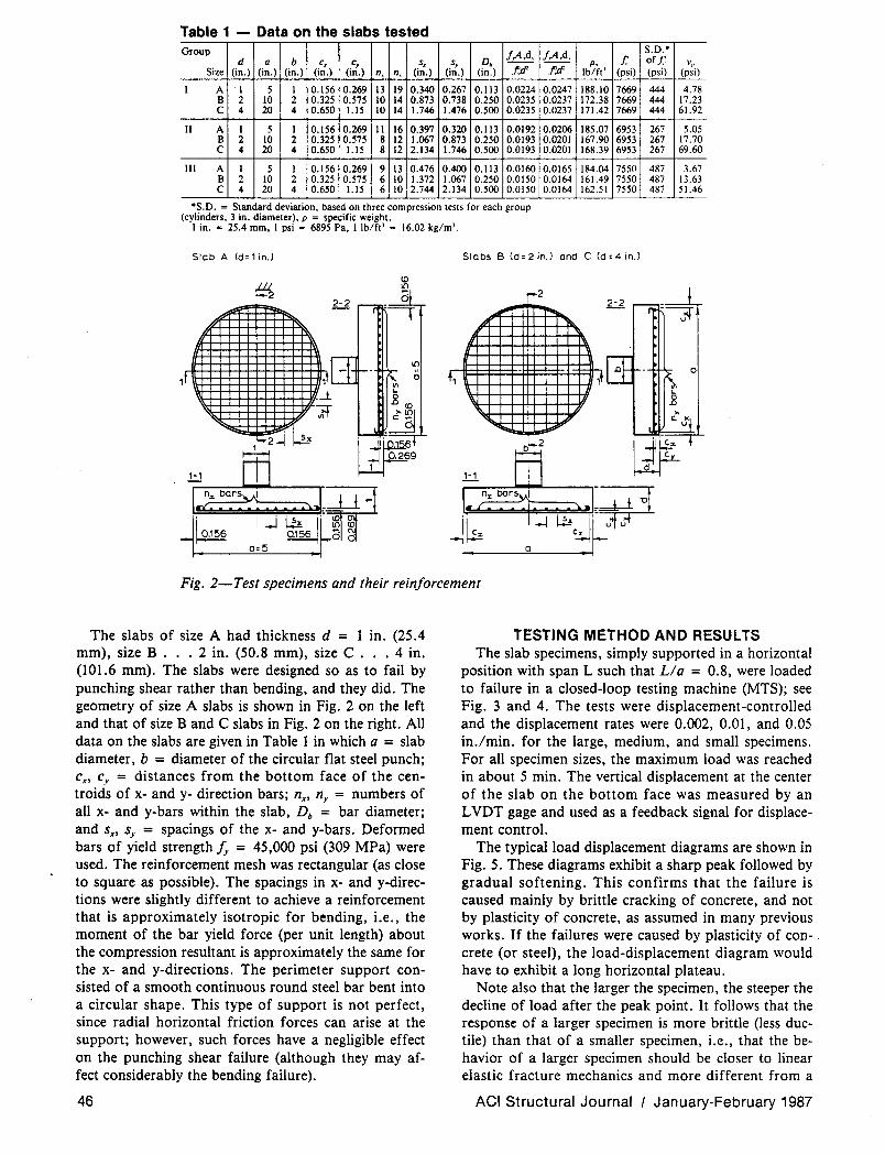
Table 1 - Data on the slabs tested Group !,A,d, f,A,.d,. S.D.·
d Q b Cx C, Sx S, Db p, /.' of/.' v" Size (in.) (in.) (in.) (in.) (in.) n, n, (in.) (in.) (in.) .t:.d' .t:.d' Ib/ft' (psi) (psi) (psi)
I A 1 5 1 0.156 0.269 13 19 0.340 0.267 0.113 0.0224 0.0247 188.10 7669 444 4.78 B 2 10 2 0.325 0.575 10 14 0.873 0.738 0.250 0.0235 0.0237 172.38 7669 444 17.23 C 4 20 4 0.650 1.l5 10 14 1.746 1.476 0.500 0.0235 0.0237 171.42 7669 444 61.92
II A 1 5 I 0.156 0.269 11 16 0.397 0.320 0.113 0.0192 0.0206 185.07 6953 267 5.05 B 2 10 2 0.325 0.575 8 12 1.067 0.873 0.250 0.0193 0.0201 167.90 6953 267 17.70 C 4 20 4 0.650 1.l5 8 12 2.134 1.746 0.500 0.0193 0.0201 168.39 6953 267 69.60
III A 1 5 1 0.156 0.269 9 13 0.476 0.400 0.113 0.0160 0.0165 184.04 7550 487 3.67 B 2 10 2 0.325 0.575 6 10 1.372 1.067 0.2S0 O.OISO 0.0164 161.49 7550 487 13.63 C 4 20 4 0.650 1.l5 6 10 2.744 2.134 O.SOO O.OISO 0.0164 162.SI 7550 487 S 1.46
·S.D. = Standard deviation, based on three compression tests for each group (cylinders, 3 in. diameter), p = specific weight.
1 in. = 25.4 mm, 1 psi = 6895 Pa, 1 Ib/ft' = 16.02 kg/m'.
Slob A (d=' in,) Slobs B (d=2in.) and C (d=4in.)
~ 2 -. ~ ....
H
t ',1 +, -I-r-l- ~ ,
oil ... ...
Fig. 2-Test specimens and their reinforcement
The slabs of size A had thickness d = 1 in. (25.4 mm), size B ... 2 in. (50.S mm), size C ... 4 in. (101.6 mm). The slabs were designed so as to fail by punching shear rather than bending, and they did. The geometry of size A slabs is shown in Fig. 2 on the left and that of size Band C slabs in Fig. 2 on the right. All data on the slabs are given in Table 1 in which a = slab diameter, b = diameter of the circular flat steel punch; cx , cy = distances from the bottom face of the centroids of x- and y- direction bars; nx, ny = numbers of all x- and y-bars within the slab, Db = bar diameter; and sx, Sy = spacings of the x- and y-bars. Deformed bars of yield strength /y = 45,000 psi (309 MPa) were used. The reinforcement mesh was rectangular (as close to square as possible). The spacings in x- and y-directions were slightly different to achieve a reinforcement that is approximately isotropic for bending, i.e., the moment of the bar yield force (per unit length) about the compression resultant is approximately the same for the x- and y-directions. The perimeter support consisted of a smooth continuous round steel bar bent into a circular shape. This type of support is not perfect, since radial horizontal friction forces can arise at the support; however, such forces have a negligible effect on the punching shear failure (although they may affect considerably the bending failure).
46
TESTING METHOD AND RESULTS The slab specimens, simply supported in a horizontal
position with span L such that L/a = O.S, were loaded to failure in a closed-loop testing machine (MTS); see Fig. 3 and 4. The tests were displacement-controlled and the displacement rates were 0.002, 0.01, and 0.05 in.lmin. for the large, medium, and small specimens. For all specimen sizes, the maximum load was reached in about 5 min. The vertical displacement at the center of the slab on the bottom face was measured by an L VDT gage and used as a feedback signal for displacement control.
The typical load displacement diagrams are shown in Fig. 5. These diagrams exhibit a sharp peak followed by gradual softening. This confirms that the failure is caused mainly by brittle cracking of concrete, and not by plasticity of concrete, as assumed in many previous works. If the failures were caused by plasticity of concrete (or steel), the load-displacement diagram would have to exhibit a long horizontal plateau.
Note also that the larger the specimen, the steeper the decline of load after the peak point. It follows that the response of a larger specimen is more brittle (less ductile) than that of a smaller specimen, i.e., that the behavior of a larger specimen should be closer to linear elastic fracture mechanics and more different from a
ACI Structural Journal I January-February 1987
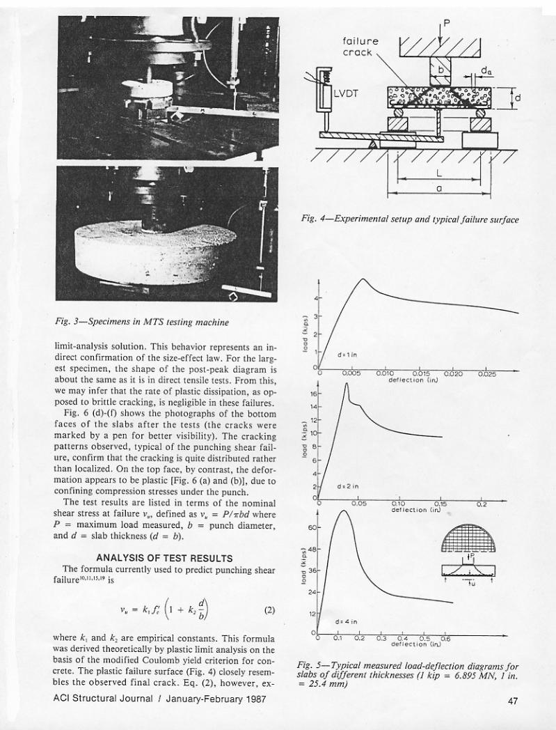
Fig _ 3_S~itMns in MTS t~tinB mac:hint
li mi l_analysil solution. This behaoior r.pr.~n!S an in· dirtt! eonlirmalion of Ih. li • .-..effecl law. For Ihe largesl 'J)«imen. Ihe .hape of Ihe pOsl-peak dialram is aooullhe ume I5 il ;s in dirtt! lensile lesll. From Ihis. we may infer Ihal Ihe rale of plaslic dissiplllion. as opposed 10 brillie crackinll. is negligible in Ihese failures.
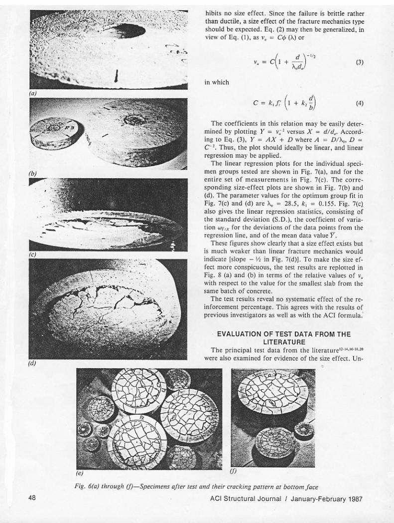
Fig . 6 (d)-(f) shows Ihe photograph. of Ihe bonom faces o f lh. dabs after the le5lS (Ihe cracks were ma rked by I pen for bener _isibilily). The .radint pauerns observed. I)'pieal of 1h. punchinllhn. failure. confirm Ihat the crackinl il quile distribuled ralher than localized. On th. lOP flce. by comrasl . Ih. deformalion appears 10 be plaslic rFi~. 6 (a) and (b)). due 10 confininB comprel-Sion Sltt.'SlCS und .. Ihe punch.
The lesl resulu are lilled in terms of Ihe nominal shear Ilresl II failure ~ •. defined as v • .. PI "bd ,,·h...-e P .. maximum load measured. b .. punch diam ... er. and d .. slab Ihie knel-S (d .. b).
ANALYSIS OF TEST RE5UL T5 The formula cufTently ustd 10 predia punchinl shear
f3ilur .... "·'~ .. il
wheie t , and t , are empirical conSlants. Thil formula "'"" deriVflilhtofC"[;caIly by pI •• tie: limil allllysis On Ihe bam of lhe modified Coulomb yield crilerion for ron_ crelc, The plastic failu,"" lurface (Fil\. 4) dosely resem bles ' he observed final crack. Eq . (2). however . ex
ACI Structural Journal I January-FebruaIY 1987
foilure
Fil. 4-ExfN"imento/ ~rup ond lypiCtJI/oilure .ur/1ICt
I
I
Fit. 5-T)"piCtJI mt:QSured 1f)(l(1-4tf/«tion diogromS!M slobs 0/ dilf~renllhkl<n=~ (I kip. 6.895 MN. 1 in . .. 25.4 mm)
"
'"
hib il' no ,ize effec~. Since ~he failure i, brinl. rather ~han ductile, a size effeCl of th. fracture mechanics typo should be expected. EQ. (2) may Ihen be ¥.nttalized. in "iew of Eq. (1). a! " . ~ C¢ (AI or
in which
C = k "(l +k,'!\ ,.J. . hj I')
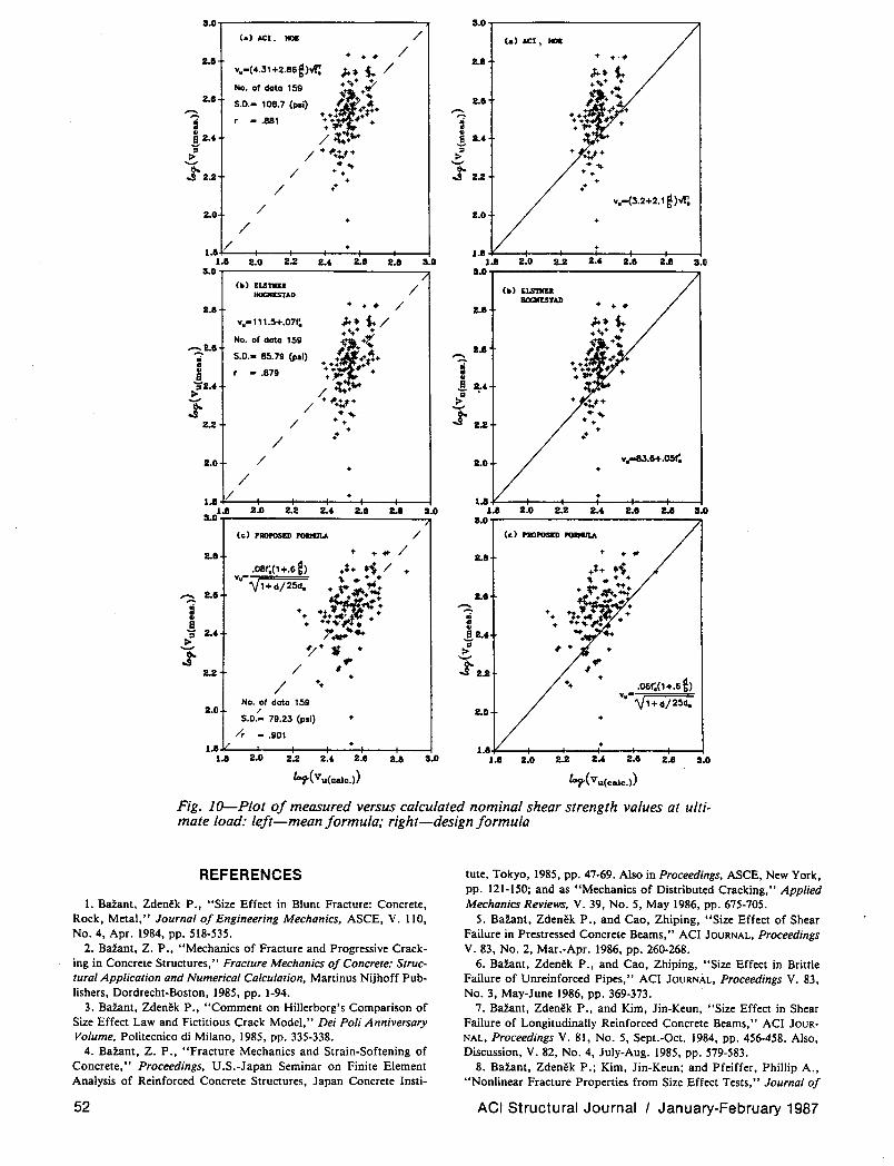
The coefficienls in thi s relal ion mal' be ea,il y delcr· mined by plolting Y ~ v:' versus X .. did •. Accord inglO Eq. (3) . Y .. AX + D wh ... A ~ DI'A,. D .. Co'. Thus. the plot . hould ideally Dc linear. and linear regression mal' be applied .
The linear rcg,ession plot< fo' Ihe indi"idual !recimen groups tcsled are ,ho"'n in Fig. 7(a). and for lhe e nt ire s .. of meaSurcment . in Fig. 7(c). Tho corre_ sponding size_effect plou or •• hown in FiS . 7(b) and (d). The parameter "alue, for the optimum group fil in Fig. 7(c) and (d) orc >.. .. 28 .5. k, .. O.15~ . Fig. 7(c) al,o give,; Ihe lin.ar r.gr.ssiOII sialisli"s. comi'ting of Ihe slandard deviation (S.D.). lhe codfici.nl of "a. ialion Wf',x for Ihc de"iations of the dala points f,om the regression line. and of Ihc mea n dala \'al "" Y.
These figu re, show clearly that • ,i~e eff~cl ex im bul is much weaker Ihan linear f.acture mechanics ","ould indicate Islope - "' in Fig . 7(d)]. To make the ,ize ef· fe<:l mOre conspicuous. the te't "-Iulll ar~ replolled in Fig . 8 (a) and (b) ;n term, o f the rclath·. "alutl of ". with resreel 10 th. val". for the sm.liest sl.b from lhe Sa me batch of concrete .
The Ie" re,ults reveal nO .ySlematic effecl of lhe reinforcement p.rcentage. Tliis agree. wit h the ,<suhs of previou, in"<sligators as well as wilh the ACI formula :
EVALUATION OF TEST DATA FROM THE LITERATURE
The principal Ie" data from Ih' lit .. ature"·"· ... "·,, ...... also examined for e"idence of Ihe .ize erreCl. Un-
F;g. 6(0) Ihr(Jugh (f)- Spe<:imens oller lesr and Ihe;r cfGchng pal/ern at bOllam lar;e
ACI Structural JO urnal I January·February 1987
2. _.00 (a) U (b)
"':! ) ""'- ....... '" ..t u
-.O~
Fig. 8-Test results relative to the result jor the smallest slab and their optimal jits
fortunately, not one of the previous test series included significantly different slab sizes. Nevertheless, in the set of all existing data, d/da ratios ranging from 4 to 12 were used by different investigators (Table 2). This suggests that a size effect might be detected by analyzing all data collectively, in the same manner as has been done with success for the diagonal shear failure of beams.5
.'
The results of 159 tests by seven previous investigatorsI2.14.16.18.2o are plotted in Fig. 9(a) and (b). Basic information on these data is summarized in Table 2. The optimum fits of these data by Eq. (4) are also plotted in Fig. 9.
ACI Structural Journal I January-February 1987
The comparisons in Fig. 9(a) and (b) do not contradict the size-effect law [or Eq. (3)], but neither do they corroborate it, because the scatter is enormous. The enormity of scatter is due to comparing the results from different laboratories obtained with different concretes and the results for slabs that were not geometrically similar. It was for this reason that the present tests were undertaken.
If the test results fitted the theory perfectly, the plot of the measured values versus the calculated values would lie on a straight line of Slope 1 passing through the origin. Thus, the deviations from this line are measures of the errors of the formula. Plots of this type are
49

Table 2 - Summary of previous test results Slab a, d, d" did, L, 1.'11> I;, Slab a, d. d .. did, L, v., I;. No. in. in. in. in. Ib psi No. in. in. in. in. Ib psi
Corley, Hawkins (1968) Kinnunen, Nylander (1960) (continuedl
28 37.10 5.94 1.250 4.76 211.50 82.690 3810 AN-I 40.00 5.75 0.750 7.67 336.00 75,100 27\0 29 37.10 5.94 1.250 4.76 211.50 93,710 3810 AH-3 40.00 5.75 0.750 7.67 336.00 91,200 3190 30 37.10 5.94 1.250 4.76 211.50 110,250 4420 BN-I 40.00 5.75 0.750 7.67 336.00 59,700 2920 31 37.\0 5.94 1.250 4.76 211.50 121.280 4420 BC-I 40.00 5.75 0.750 7.67 336.00 71,800 2870 32 37. \0 6.\0 1.250 4.88 211.50 57.990 3870 BH-I 40.00 5.75 0.750 7.67 336.00 88,500 2960 33 37.\0 6.14 1.250 4.91 211.50 57,990 3920 BH-2 40.00 5.75 0.750 7.67 336.00 67.700 2620 34 37.10 5.90 1.250 4.72 21!.50 74.530 4030 BH-3 40.00 5.75 0.750 7.67 336.00 90,400 3130 35 37.10 6.02 1.250 4.82 211.50 74.530 3680 BN-I-PI4 40.00 5.75 0.750 7.67 336.00 61,700 3680 36 37.\0 5.98 1.250 4.79 211.50 63,060 3960 BH-2-PI4 40.00 5.75 0.750 7.67 336.00 60,600 2780 37 37.\0 6.02 1.250 4.82 211.50 62,180 3950 BH-3-PI4 40.00 5.75 0.750 7.67 336.00 80.300 3100 38 37.10 6.02 1.250 4.82 211.50 79,820 4210 BN-I-SI4 40.00 5.75 0.750 7.67 336.00 54,800 3320 39 37.10 6.06 1.250 4.85 211.50 79,820 3930 BH-2-SI4 40.00 5.75 0.750 7.67 336.00 60.300 2960 40 37.10 6.02 1.250 4.82 211.50 67,250 3610 BH-3-SI4 40.00 5.75 0.750 7.67 336.00 84,200 3520 41 37.10 5.90 1.250 4.72 211.50 67,470 3880 BN-I-57 40.00 5.75 0.750 7.67 336.00 67,900 3700 42 37.10 6.02 1.250 4.82 211.50 85,330 4100 BH-2-S7 40.00 5.75 0.750 7.67 336.00 77,700 3480 43 37.10 6.02 1.250 4.82 211.50 96,360 4030 BH-3-57 40.00 5.75 0.750 7.67 336.00 89,900 3740
Moe (1%1) Dragosavic, Van den Reukel (1974)
SI-60 40.00 6.00 0.375 12.00 288.00 87,500 3380
I 9.44 1.40 0.315 4.44 58.75 7190 4450 S2-60 40.00 6.00 0.375 12.00 288.00 80,000 3200
2 9.44 1.40 0.315 4.44 58.75 7420 4450 53-60 40.00 6.00 0.375 12.00 288.00 81,750 3280
3 9.44 1.40 0.315 4.44 58.75 5840 4450 S4-6O 40.00 6.00 0.375 12.00 288.00 75,000 3460
4 9.44 1.40 0.315 4.44 58.75 4050 3190 SI-70 40.00 6.00 0.375 12.00 288.00 88,200 3550
5 9.44 1.40 0.315 4.44 58.75 7010 3210 S3-70 40.00 6.00 0.375 12.00 288.00 85,000 3680
6 9.44 1.40 0.315 4.44 58.75 6290 3210 54-70 40.00 6.00 0.375 12.00 288.00 84,000 5100 S4A-70 40.00 6.00 0.375 12.00 288.00 70,000 2970 7 9.44 \.40 0.315 4.44 58.75 7550 3430 SS-60 32.00 6.00 0.375 12.00 288.00 77,000 3220 8 9.44 \.40 0,315 4.44 58.75 8990 3720 S6-6O 32.00 6.00 0.375 12.00 288.00 72.000 3110 9 9.44 1.40 0.315 4.44 58.75 7190 3720 S7-60 32.00 6.00 0.375 12.00 288.00 94.750 3340 10 9.44 \.40 0.315 4.44 58.75 3460 3610 S8-6O 32.00 6.00 0.375 12.00 288.00 82,500 3340 II 9.44 \.40 0.315 4.44 58.75 4740 3610
12 9.44 \.40 0.315 4.44 58.75 5840 3420 55-70 32.00 6.00 0.375 12.00 288.00 85,000 3340 86-70 32.00 6.00 0.375 12.00 288.00 85,000 3520 13 9.44 1.40 0.315 4.44 58.75 5840 3420 MIA 37.70 6.00 0.375 12.00 288.00 97,300 3020 14 9.44 \.40 0.315 4.44 58.75 7190 3420 MlA 37.70 6.00 0.375 12.00 288.00 47,800 2250 IS 9.44 1.40 0.315 4.44 58.75 7190 3420
16 9.44 \.40 0.315 4.44 58.75 7190 3420 M4A 37.70 6.00 0.375 12.00 288.00 32,300 2560 M2 37.70 6.00 0.375 12.00 288.00 65,700 3730 M3 37.70 6.00 0.375 12.00 288.00 46,600 3300 Eistner, Hognostad (1956) M6 31.40 6.00 0.375 \2.00 288.00 53,800 3840 M7 31.40 6.00 0.375 12.00 288.00 70,000 3620
A-Ia 40.00 6.00 1.000 6.00 288.00 68,000 2040 M8 31.40 6.00 0.375 12.00 288.00 33,600 3570 A-Ib 40.00 6.00 1.000 6.00 288.00 82,000 3660 M9 3\.40 6.00 0.375 12.00 288.00 60,000 3370 A-Ie 40.00 6.00 1.000 6.00 288.00 80,000 4210 MIO 3\.40 6.00 0.375 12.00 288.00 40,000 3060 A-Id 40.00 6.00 1.000 6.00 288.00 78,000 5340 A-Ie 40.00 6.00 1.000 6.00 288.00 80,000 2940 Mowrer, Vanderbilt (1%7) A-la 40.00 6.00 1.000 6.00 288.00 75,000 1980 A-2b 40.00 6.00 1.000 6.00 288.00 90,000 2830 M-2-I-O 16.00 3.00 0.750 4.00 192.00 19,300 4140 A-2e 40.00 6.00 1.000 6.00 288.00 105,000 5430 M-2-2-O 16.00 3.00 0.750 4.00 192.00 22,900 3610 A-2b 40.00 6.00 1.000 6.00 288.00 115,000 4050 M-3-I-O 24.00 3.00 0.750 4.00 192.00 17,800 3060 A-3a 40.00 6.00 1.000 6.00 288.00 80,000 1850 M-3-2-0. 24.00 3.00 0.750 4.00 192.00 22,300 26\0 A-3b 40.00 6.00 1.000 6.00 288.00 100,000 3280 M-3-2-O" 24.00 3,00 0.750 4.00 192.00 38,600 7800 A-4 56,00 6.00 1.000 6.00 288.00 90,000 3790 M-4-I-O 32.00 3.00 0.750 4.00 192.00 20,800 2250 A-5 56.00 6.00 1.000 6.00 288.00 120,000 4030 M-4-2-O 32.00 3.00 0.750 4.00 192.00 29,800 3940 A-6 56.00 6.00 1.000 6.00 288.00 112,000 3630 M-5-I-O 40.00 3.00 0.750 4.00 192.00 24,500 3380 A-7 40.00 6.00 1.000 6.00 288.00 90,000 4130 M-5-2-O 40.00 3.00 0.750 4.00 192.00 34,100 3320 A-8 56.00 6.00 1.000 6.00 288.00 98,000 3180 M-6-I-O 48.00 3.00 0.750 4.00 192.00 26,700 4060 A-7a 40.00 6.00 1.000 6.00 288.00 63,000 4050 M-6-2-O 48.00 3.00 0.750 4.00 ·192.00 35,600 3830 A-9 40.00 6.00 1.000 6.00 288.00 100,000 4330 M-7-I-O 56.00 3.00 0.750 4.00 192.00 31,100 4020 A-IO 56.00 6.00 1.000 6.00 288.00 110,000 4310 M-7-2-O 56.00 3.00 0.750 4.00 192.00 41,500 3630 A-II 56.00 6.00 1.000 6.00 288.00 119,000 3760 M-8-I-O 64.00 3.00 0.750 4.00 192.00 32,600 3610 A-12 56.00 6.00 1.000 6.00 288.00 1\9,000 4120 M-8-2-O 64.00 3.00 0.750 4.00 192.00 41,500 3560
M-3-1-2 24.00 3.00 0.750 4.00 192.00 22,900 3920 Kinnunen, Nylander (1960) M-3-1-4. 24.00 3.00 0.750 4.00 192.00 22,300 3060
M-3-1-4. 24.00 3.00 0.750 4.00 192.00 25,200 2900 M-3-2-4 24.00 3.00 0.750 4.00 192.00 23,700 2460
3 18.55 5.94 1.250 4.76 211.50 50,490 3700 4 18.55 5.90 1.250 4.72 211.50 37,930 3810 Taylor, Hayes (1%5) 5 18.55 5.87 1.250 4.69 211.50 57,330 3940 6 18.55 5.97 1.250 4.76 211.50 61,740 3860 I 8.00 3.00 0.375 8.00 140.00 8500 4260 7 18.55 6.02 1.250 4.81 211.50 55,570 4200 2 8.00 3.00 0.375 8.00 140.00 8900 3760 8 18.55 6.02 1.250 4.81 211.50 55,570 4200 3 12.00 3.00 0.375 8.00 -140.00 13,000 4120 9 18.55 5.90 1.250 4.72 211.50 61,740 3820 4 16.00 3.00 0.375 8.00 140.00 15,000 4120·
10 18.55 5.90 1.250 4.72 211.50 61,740 3820 5 20.00 3.00 0.375 8.00 140.00 11,950 3160 \I 18.55 6.02 1.250 4.81 211.50 74,970 4720 6 24.00 3.00 0.375 8.00 140.00 14,400 3160 12 18.55 6.06 1.250 4.85 211.50 74,530 4550 7 8.00 3.00 0.375 8.00 140.00 7Z50 3760 13 18.55 5.90 1.250 4.72 211.50 42,340 4210 8 8.00 3.00 0.375 8.00 140.00 8380 3760 14 18.55 6.02 1.250 4.81 211.50 46,750 3810 9 12.00 3.00 0.375 8.00 140.00 9)00 3560 15 18.55 6.10 1.250 4.88 211.50 42,340 3880 10 12.00 3.00 0.375 8.00 140.00 11,500 3560 16 18.55 6.02 1.250 4.81 211.50 50,490 3930 \1 16.00 3.00 0.375 8.00 140.00 8750 3360 17 18.55 6.02 1.250 4.81 211.50 51,160 3930 12 16.00 3.00 0.375 8.00 140.00 13,950 3360 18 18.55 5.90 1.250 4.72 211.50 45,640 3990 13 20.00 3.00 0.375 8.00 140.00 9850 3200 19 18.55 5.84 1.250 4.69 211.50 44,540 4190 14 20.00 3.00 0.375 8.00 140.00 14,500 3200 20 18.55 5.98 1.250 4.79 211.50 59,980 4000 IS 24.00 3.00 0.375 8.00 140.00 9850 2660 21 18.55 5.90 1.250 4.72 211.50 63,950 3970 16 24.00 3.00 0.375 8.00 140.00 15,750 2660 22 37.10 6.06 1.250 4.85 211.50 57,110 4160 J7 8.00 3.00 0.375 8.00 140.00 8000 3300 23 37.10 5.94 1.250 4.76 211.50 46,750 4010 18 8.00 3.00 0.375 8.00 140.00 8000 3300 24 37.10 6.22 1.250 4.98 211.50 %,580 3880 19 16.00 3.00 0.375 8.00 140.00 11,750 3280 25 37.10 6.06 1.250 4.85 211.50 9\,730 3690 20 16.00 3.00 0.375 8.00 140.00 13,500 3280 26 37.10 6.06 1.250 4.85 211.50 90,850 3880 21 24.00 3.00 0.375 8.00 140.00 15,300 3140 27 37.10 6.06 1.250 4.85 211.50 79,820 3890 22 24.00 3.00 0.375 8.00 140.00 17,250 3140
50 ACI Structural Journal I January-February 1987
?~------------------------~
(a) X Corley. _1 •• (1968)
8
6
,:c 0,..' .... 1c. Y •• den Beutel (1974)
t:. E1stner. Hogoe ... d (1956)
• Kinnunen. 'tYhrtder (1960)
+ .... (1961)
C!) -.or. Y_rbflt (1967)
+ 7..,lor • ...,... (1965)
o Ioiont. e.. (1985)
· . •
· · . ·
~-25 •
· . 2 ."
0 0 • 8 12
did. 18 20
.I~--------------------------'
(b)
..
.2
-.2
-.. ..
C-.08f.(1+.6f>
~2!i •
, . • ..
...Wneor
.
.1 1.0 1.2 1 .•
r..,.(d/d.)
Fig. 9-Ultimate load data from the literature and optimal fit by size-effect law
shown in Fig. 10 (a) through (d) (where r is the correlation coefficient of regression). The theoretical values for the formulas of Elstner and Hognestad l4 and Moe 17
are given by Vu = kl + kJ~ (no effect of d/b) and Vu
= kl + k3 d/b) .JJ[, respectively. (The latter formula is equivalent to that of ACI since k3 = k 1k2.) The coefficient values for mean ultimate load predictions are kl = 4.31, k2 = 0.66 for the ACI formula; kl = 111.5, k2 = 0.067 for Elstner and Hognestad's formula l4 and kl = 4.31, k3 = 2.86 for Moe's formula l7 (2.86 = 4.31 x 0.664).
The comparisons of the data points with the theoretical lines (dashed) in Fig. 10 (a) through (c) show huge scatter, as indicated by the vertical deviations from the dashed line (the regression line is not plo~ted). The proposed formula [Eq. (4)] has only marginally better statistics than the previous formulas, and the comparison in Fig. lO(c) cannot be viewed at all as either a verification or an invalidation of Eq. (4) proposed here.
The design values Vu of nominal shear stress are obtained by applying to the formula a capacity reduction factor 0.75. The plots of such reduced nominal shear stress values versus the measured values are shown in Fig. 10 (d) through (f). In these plots, the majority of data are expected to lie above the theoretical straight line, as basically they do, although a few data points still fall dangerously low below the prediction line. This happens even when the size effect is introduced [Fig. 10(f)]; the variation coefficient and the correlation coefficient are only marginally better for this graph [Fig. 1O(f)].
The scatter of the data points in Fig. 10 is very large. Apparently, aside from the effects of b/ d and size, there are some other systematic influences which are not yet understood.
ACI Structural Journal I January-February 1987
CONCLUSIONS 1. The punching shear failure of slabs without stir
rups is not plastic but brittle. This is evidenced by the fact that, after the peak, the load-deflection diagram exhibits a gradual decline rather than a plastic yield plateau. Due to the brittleness of failure, the size-effect law for blunt failures should, in theory, apply.
2. The punching shear tests of geometrically similar concrete slabs of different sizes,· carried out as part of the present investigation, indicate that the size effect exists, i.e., the nominal stress at failure decreases as the size increases. These new test results show acceptable agreement with the size-effect law, and lead to an im-proved design formula [Eq. (3)]. .
3. The larger the slab thickness, the steeper the postpeak decline of the load-deflection diagram; thus, the punching shear behavior of thin slabs is closer to plasticity, and that of thick slabs is Closer to linear elastic fracture mechanics. This independently confirms the applicability of the size-effect law, since this law predicts exactly such kind of behavior. - 4. Previous test data from the literature do not contradict the proposed formula but they do not validate it either, due to their enormous scatter when they are all analyzed collectively.
5. In view of the limited number of tests, the not very broad size range, and the use of small aggregate (maximum size '14 in. or 6.35 mm), it would be desirable to conduct further geometrically similar size-effect tests with much larger slabs and a regular-size aggregate (this would of course require much larger funding).
ACKNOWLEDGMENT The fundamental investigations underlying the present work were
supported by U.S. Air Force Office of Scientific Research under Grant No. 83-0009.
51
3.0 3.0
(.) ACI. IIOS / (a) ACI, _
+ + • / + +-. 2.8 v.-( 4.31 +2.86 g)~ ;.. i.- /
2.8
No. of data 159 +<t;,+ .;-
2.8 ~~+ .. 2.11 S.O.- 108.7 (poi) 14 .. ..+ + ....... ~
- .881 +++ .t+" ~
Ii r ++ + .. .. + .. ilu / <l;+t.+
.. 2.' S
';' / +~:l+ ';'
> > '-" * .. '-"
.tZ.2 / + + .t2.2 + / ++ ++
/ v.-(3.2+2.1 g )-.'f;.
2.0 2.0
/ + +
1.11 /
1.8 1.8 2.0 2.2 2., 2.11 2.11 3.0 1.8 Z.O 2.2 2., Z.II Z.8 3.0
3.0 /
3.0
(b) ILSn,u / (b) ELSnn:R IIOCNESTAD
+ + • / IIOCIIISTAD + + • 2.8 2.11
v.-l 1 1.5+.07r. ;..i.-/ .. +.+ ..
No. of data 159 ~~+t ~2.8 S.O.- 85.79 (pol) ~.#+
2.11 Ii ~ .. +.+ .. + '-'+ .. Ii " r - .879 .. e .)1+ ..
;FU / <l;+ .! 2:' -- +~V+ .: .t / -* ..
.t 2.2 / + + 2.2 +
/ ++ .+
2.0 / 2.0 v.-83.6+ .05(. + +
/ 1/ • 1.8
+ 1.8
1.11 2.0 2.2 2.' 2.11 U 3.0 1.8 2.0 2.2 2., 2.8 U 3.0 3.0 3.0
(c) PROPOSED POIIKJl.\ / (c) PROPOSED POIIKJl.\
2.11 • + .. / • + .. U
.08(,(1+.6 f) .*+ .'S / + v,,· '\. .... " .. 2.8
Y1+d/ 25d. + \*~~ ~ ~++ 1.8
~ <+ ....... • ~~..., ~ + ~ • " + .. • e + +.'\f~. + .. + .. ;! 2., 7 ....... .!I.,
J ~+ " + .: -
2.2 / # .. .t2.2
++ +
++ +
.06(,(1+.6 f) / No. of data 159 v.-l!1+d/25d.
2.0 / 2.0 S.O.- 79.23 (pai) + +
/r - .901 1.8 + •
1.8 2.0 2.2 2.' 2.11 2.11 3.0 2.0 2.2 2-' 2.8 2.8 3.0
~(VU(CalC) ~(V"(Calc.»)
Fig. lO-Plot of measured versus calculated nominal shear strength values at ultimate load: left-mean formula; right-design formula
REFERENCES
1. BaZant, Zden!k P., "Size Effect in Blunt Fracture: Concrete, Rock, Metal," Journal of Engineering Mechanics, ASCE, V. 110, No.4, Apr. 1984, pp. 518-535.
2. BaZant, Z. P., "Mechanics of Fracture and Progressive Cracking in Concrete Structures," Fracture Mechanics of Concrete: Structural Application and Numerical Calculation, Martinus Nijhoff Publishers, Dordrecht-Boston, 1985, pp. 1-94.
3. BaZant, Zden!k P., "Comment on Hillerborg's Comparison of Size Effect Law and Fictitious Crack Model," Dei Poli Anniversary Volume, Politecnico di Milano, 1985, pp. 335-338.
4. BaZant, Z. P., "Fracture Mechanics and Strain-Softening of Concrete," Proceedings, U.S.-Japan Seminar on Finite Element Analysis of Reinforced Concrete Structures, Japan Concrete Insti-
52
tute, Tokyo, 1985, pp. 47-69. Also in Proceedings, ASCE, New York, pp. 121-150; and as "Mechanics of Distributed Cracking," Applied Mechanics Reviews, V. 39, No.5, May 1986, pp. 675-705.
5. BaZant, Zden!k P., and Cao, Zhiping, "Size Effect of Shear Failure in Prestressed Concrete Beams," ACI JOURNAL, Proceedings V. 83, No.2, Mar.-Apr. 1986, pp. 260-268.
6. BaZant, Zden!k P., and Cao, Zhiping, "Size Effect in Brittle Failure of Unreinforced Pipes," ACI JOURNAL, Proceedings V. 83, No.3, May-June 1986, pp. 369-373.
7. BaZant, Zden!k P., and Kim, Jin-Keun, "Size Effect in Shear Failure of Longitudinally Reinforced Concrete Beams," ACI JOURNAL, Proceedings V. 81, No.5, Sept.-Oct. 1984, pp. 456-458. Also, Discussion, V. 82, No.4, July-Aug. 1985, pp. 579-583.
8. BaZant, Zdenek P.; Kim, Jin-Keun; and Pfeiffer, Phillip A., "Nonlinear Fracture Properties from Size Effect Tests," Journal of
ACI Structural Journal I January-February 1987
Structural Engineering, ASCE, V. 112, No.2, Feb. 1986, pp. 289-307.
9. BaZant, Zden~k, and Oh, B. H., "Crack Band Theory for Fracture of Concrete," Materials and Structures, Research and Testing (RILEM, Paris), V. 16, No, 93, May-June 1983, pp. 155-117.
10. Braestrup, M. W., "Punching Shear in Concrete Slabs," Lie. Techn. thesis, Structural Research Laboratory, Technical University of Denmark, Lyngby, 1976.
II. Chen, Wai-Fah, Plasticity in Reinforced Concrete, McGrawHill Book Co., New York, 1982, pp. 329-332.
12. Corley, W. Gene, and Hawkins, Neil M., "Shearhead Reinforcement for Slabs," ACI JOURNAL, Proceedings V. 65, No. 10, Oct. 1968, pp. 811-824.
13. Dragosavic, M., and Van den Beukel, A., "Punching Shear ," Heron (Delft), V. 20, No.2, 1974,48 pp.
14. Elstner, Richard C., and Hognestad, Eivind, "Shearing Strength of Reinforced Concrete Slabs," ACI JOURNAL, Proceedings V. 53, No. I, July 1956, pp. 29-58.
IS. Hess, U., and Jensen, B. C., "Gennemlokning af jernbeton plader," Report No. R90, Structural Research Laboratory, Technical University of Denmark, Lyngby, May 1978,63 pp.
ACI Structural Journal I January-February 1987
16. Kinnunen, S., and Nylander, H., "Punching of Concrete Slabs without Shear Reinforcement," Transactions, Royal Institute of Technology, Stockholm, 1960, 110 pp.
17. Moe, Johannes, "Shear Strength of Reinforced Concrete Slabs and Footings Under Concentrated Load," Development Department Bulletin No. D47, Portland Cement Association, Skokie, 1961, 135 pp.
18. Mowrer, R. D., and Vanderbilt, M. D., "Shear Strength of Lightweight Aggregate Reinforced Concrete Flat Plates," ACI JOURNAL, Proceedings V. 64, No. 11, Nov. 1967, pp. 722-729.
19. Nielsen, M. P.; Braestrup, M. W.; Jensen, B. C.; and Bach, F., "Concrete Plasticity. Beam Shear-Shear in Joints-Punching Sheear," Special Publication, Danish Society for Structural Science and Engineering, Copenhagen, 1978, 129 pp.
20. Taylor, R., and Hayes, B., "Some Tests on the Effect of Edge Restraint on Punching Shear in Reinforced Concrete Slabs," Magazine of Concrete Research (London), V. 17, No. 50, Mar. 1965, pp. 39-44.
21. Baunt, Z. P., and Sener, S., "Size Effect in Torsional Failure of Beams," Report No. 86-8/428, Center for Concrete and Geomaterials, Northwestern University, Evanston, Aug. 1986,21 pp.
53