Embed Size (px)
Citation preview
SITRANS F flowmetersSITRANS F M
Flow sensor MAG 3100
4/75Siemens FI 01 · 2010
4
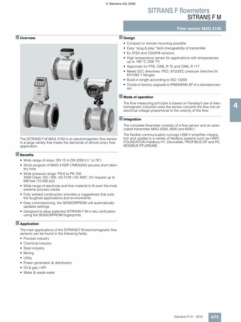
■ Overview
The SITRANS F M MAG 3100 is an electromagnetic flow sensor in a large variety that meets the demands of almost every flow application.
■ Benefits
• Wide range of sizes: DN 15 to DN 2000 (½” to 78”)• Stock program of MAG 3100P (7ME6340) secures short deliv-
ery time• Wide pressure range: PN 6 to PN 100
ANSI Class 150 / 300, AS 2129 / AS 4087. On request up to 690 bar (10 000 psi)
• Wide range of electrode and liner material to fit even the most extreme process media
• Fully welded construction provides a ruggedness that suits the toughest applications and environments
• Easy commissioning, the SENSORPROM unit automatically updates settings.
• Designed to allow patented SITRANS F M in-situ verification using the SENSORPROM fingerprints.
■ Application
The main applications of the SITRANS F M electromagnetic flow sensors can be found in the following fields:• Process industry• Chemical industry• Steel industry• Mining• Utility• Power generation & distribution• Oil & gas / HPI• Water & waste water
■ Design
• Compact or remote mounting possible• Easy “plug & play“ field changeability of transmitter• Ex ATEX and CSA/FM versions• High temperature sensor for applications with temperatures
up to 180 °C (356 °F)• Approvals for PTB, OIML R 75 and OIML R 117• Meets EEC directives: PED, 97/23/EC pressure directive for
EN1092-1 flanges• Build-in length according to ISO 13359• Onsite or factory upgrade to IP68/NEMA 6P of a standard sen-
sor.
■ Mode of operation
The flow measuring principle is based on Faraday’s law of elec-tromagnetic induction were the sensor converts the flow into an electrical voltage proportional to the velocity of the flow.
■ Integration
The complete flowmeter consists of a flow sensor and an asso-ciated transmitter MAG 5000, 6000 and 6000 I.
The flexible communication concept USM II simplifies integra-tion and update to a variety of fieldbus systems such as HART, FOUNDATION Fieldbus H1, DeviceNet, PROFIBUS DP and PA, MODBUS RTU/RS485.
© Siemens AG 2009

SITRANS F flowmetersSITRANS F M
Flow sensor MAG 3100
4/76 Siemens FI 01 · 2010
4
Pressure-temperature curve to EN (DIN) flanges, material A 105 carbon steel
Pressure-temperature curve to EN (DIN) flanges ANSI 304
Pressure-temperature curve to EN (DIN) flanges ANSI 316
Pressure-temperature curve to ANSI B16.5 flanges
Note: The pressure-temperature curves only assist in the selec-tion of a system. No responsibility is taken for the correctness of the information. For exact data please refer to the PED require-ments.
Pressure - Temperature curve to EN (DIN) Flanges Material A 105 Carbon steel
bar
ºC18015010050-10-20
PN 6PN 10PN 16
PN 25
PN 40
PN 63
PN 100
120
100
80
60
40
20
0
Pressure - Temperature curve to EN (DIN) ANSI 304
bar
ºC18015010050-10-20
PN 6PN 10PN 16
PN 25
PN 40
605040302010
0
100908070
Pressure - Temperature curve to EN (DIN) Flanges ANSI 316
bar
ºC15010050-10-20
PN 10PN 16
PN 25
PN 40
60
50
4030
100
90
8070
20
10
0
Pressure - Temperature curve to ANSI B16.5 flanges
A 105 Class 300
AISI 316 Class 150
AISI 304 Class 150
A 105 Class 150
A 105 Class 300
AISI 316 Class 150
AISI 304 Class 150
A 105 Class 150
psi
ºF400300200-100-20
600
500
800
700
400
300
200
100
0
© Siemens AG 2009
SITRANS F flowmetersSITRANS F M
Flow sensor MAG 3100
4/77Siemens FI 01 · 2010
4
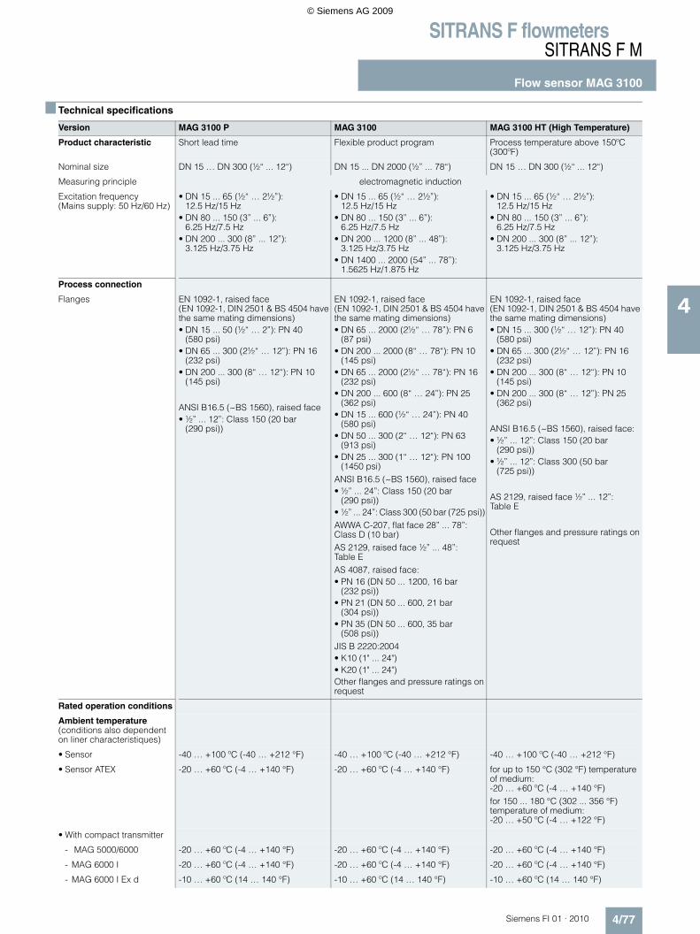
■ Technical specifications
Version MAG 3100 P MAG 3100 MAG 3100 HT (High Temperature)
Product characteristic Short lead time Flexible product program Process temperature above 150ºC (300ºF)
Nominal size DN 15 … DN 300 (½“ ... 12“) DN 15 ... DN 2000 (½” ... 78“) DN 15 … DN 300 (½“ ... 12“)
Measuring principle electromagnetic induction
Excitation frequency(Mains supply: 50 Hz/60 Hz)
• DN 15 ... 65 (½“ … 2½”):12.5 Hz/15 Hz
• DN 80 ... 150 (3” ... 6”): 6.25 Hz/7.5 Hz
• DN 200 ... 300 (8” ... 12”): 3.125 Hz/3.75 Hz
• DN 15 ... 65 (½“ … 2½”): 12.5 Hz/15 Hz
• DN 80 ... 150 (3” ... 6”): 6.25 Hz/7.5 Hz
• DN 200 ... 1200 (8” ... 48”): 3.125 Hz/3.75 Hz
• DN 1400 ... 2000 (54” ... 78”): 1.5625 Hz/1.875 Hz
• DN 15 ... 65 (½“ … 2½”): 12.5 Hz/15 Hz
• DN 80 ... 150 (3” ... 6”): 6.25 Hz/7.5 Hz
• DN 200 ... 300 (8” ... 12”): 3.125 Hz/3.75 Hz
Process connection
Flanges EN 1092-1, raised face (EN 1092-1, DIN 2501 & BS 4504 have the same mating dimensions)• DN 15 ... 50 (½“ … 2”): PN 40
(580 psi)• DN 65 ... 300 (2½“ … 12”): PN 16
(232 psi)• DN 200 ... 300 (8“ … 12“): PN 10
(145 psi)
ANSI B16.5 (~BS 1560), raised face• ½” ... 12”: Class 150 (20 bar
(290 psi))
EN 1092-1, raised face (EN 1092-1, DIN 2501 & BS 4504 have the same mating dimensions)• DN 65 ... 2000 (2½“ … 78”): PN 6
(87 psi)• DN 200 ... 2000 (8“ … 78“): PN 10
(145 psi)• DN 65 ... 2000 (2½“ … 78“): PN 16
(232 psi)• DN 200 ... 600 (8“ … 24”): PN 25
(362 psi)• DN 15 ... 600 (½“ … 24”): PN 40
(580 psi)• DN 50 ... 300 (2“ … 12“): PN 63
(913 psi)• DN 25 ... 300 (1“ … 12“): PN 100
(1450 psi)ANSI B16.5 (~BS 1560), raised face • ½” ... 24”: Class 150 (20 bar
(290 psi))• ½” ... 24”: Class 300 (50 bar (725 psi)) AWWA C-207, flat face 28” ... 78”: Class D (10 bar)AS 2129, raised face ½” ... 48”: Table EAS 4087, raised face: • PN 16 (DN 50 ... 1200, 16 bar
(232 psi))• PN 21 (DN 50 ... 600, 21 bar
(304 psi))• PN 35 (DN 50 ... 600, 35 bar
(508 psi))JIS B 2220:2004• K10 (1" ... 24")• K20 (1" ... 24")Other flanges and pressure ratings on request
EN 1092-1, raised face (EN 1092-1, DIN 2501 & BS 4504 have the same mating dimensions)• DN 15 ... 300 (½“ … 12”): PN 40
(580 psi)• DN 65 ... 300 (2½“ … 12”): PN 16
(232 psi)• DN 200 ... 300 (8“ … 12“): PN 10
(145 psi)• DN 200 ... 300 (8“ … 12”): PN 25
(362 psi)
ANSI B16.5 (~BS 1560), raised face:• ½” ... 12”: Class 150 (20 bar
(290 psi))• ½” ... 12”: Class 300 (50 bar
(725 psi))
AS 2129, raised face ½” ... 12”: Table E
Other flanges and pressure ratings on request
Rated operation conditions
Ambient temperature (conditions also dependent on liner characteristiques)
• Sensor -40 … +100 ºC (-40 … +212 °F) -40 … +100 ºC (-40 … +212 °F) -40 … +100 ºC (-40 … +212 °F)
• Sensor ATEX -20 … +60 ºC (-4 … +140 °F) -20 … +60 ºC (-4 … +140 °F) for up to 150 °C (302 °F) temperature of medium:-20 … +60 ºC (-4 … +140 °F)for 150 ... 180 °C (302 ... 356 °F)temperature of medium:-20 … +50 ºC (-4 … +122 °F)
• With compact transmitter
- MAG 5000/6000 -20 … +60 ºC (-4 … +140 °F) -20 … +60 ºC (-4 … +140 °F) -20 … +60 ºC (-4 … +140 °F)
- MAG 6000 I -20 … +60 ºC (-4 … +140 °F) -20 … +60 ºC (-4 … +140 °F) -20 … +60 ºC (-4 … +140 °F)
- MAG 6000 I Ex d -10 … +60 ºC (14 … 140 °F) -10 … +60 ºC (14 … 140 °F) -10 … +60 ºC (14 … 140 °F)
© Siemens AG 2009
SITRANS F flowmetersSITRANS F M
Flow sensor MAG 3100
4/78 Siemens FI 01 · 2010
4
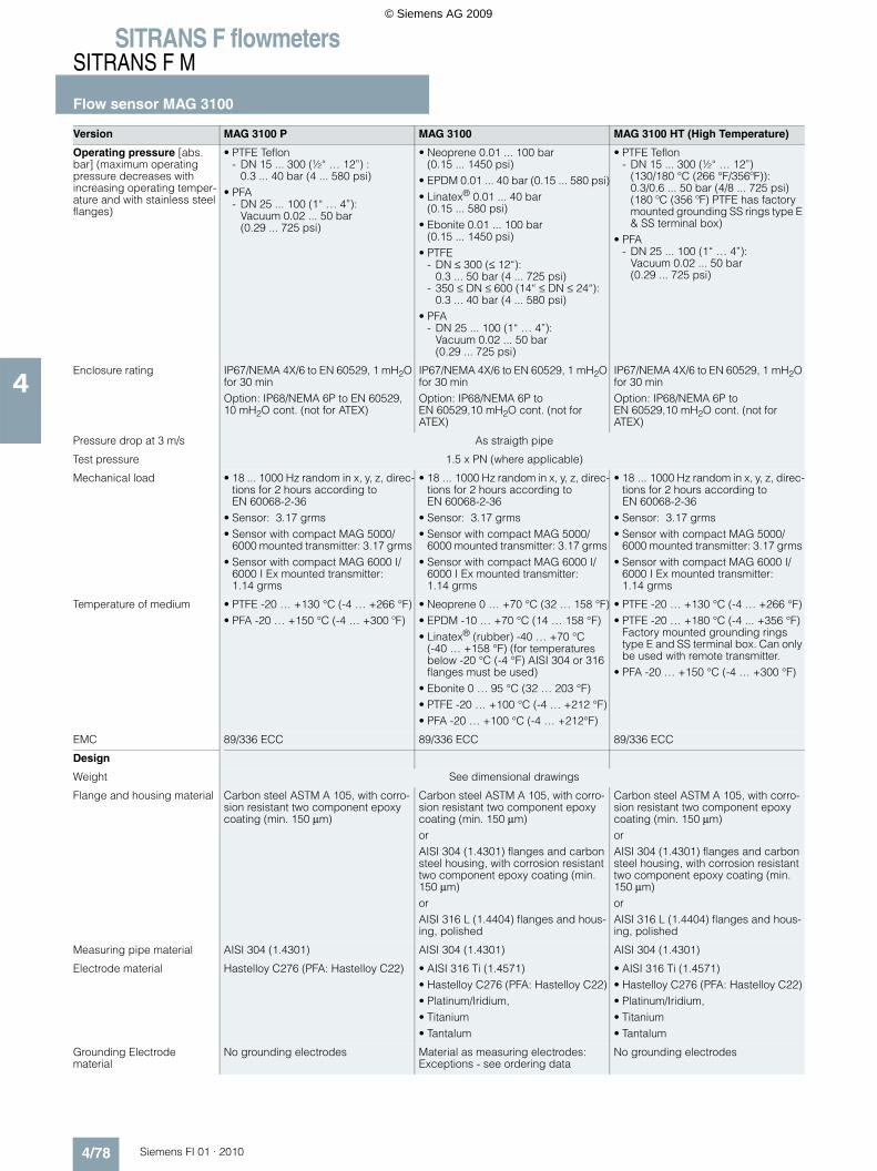
Version MAG 3100 P MAG 3100 MAG 3100 HT (High Temperature)
Operating pressure [abs. bar] (maximum operating pressure decreases with increasing operating temper-ature and with stainless steel flanges)
• PTFE Teflon- DN 15 ... 300 (½“ … 12”) :
0.3 ... 40 bar (4 ... 580 psi)• PFA
- DN 25 ... 100 (1“ … 4”): Vacuum 0.02 ... 50 bar (0.29 ... 725 psi)
• Neoprene 0.01 ... 100 bar (0.15 ... 1450 psi)
• EPDM 0.01 ... 40 bar (0.15 ... 580 psi)• Linatex® 0.01 ... 40 bar
(0.15 ... 580 psi)• Ebonite 0.01 ... 100 bar
(0.15 ... 1450 psi)• PTFE
- DN ≤ 300 (≤ 12“):0.3 ... 50 bar (4 ... 725 psi)
- 350 ≤ DN ≤ 600 (14“ ≤ DN ≤ 24“):0.3 ... 40 bar (4 ... 580 psi)
• PFA- DN 25 ... 100 (1“ … 4”):
Vacuum 0.02 ... 50 bar (0.29 ... 725 psi)
• PTFE Teflon- DN 15 ... 300 (½“ … 12”)
(130/180 °C (266 °F/356ºF)):0.3/0.6 ... 50 bar (4/8 ... 725 psi) (180 ºC (356 ºF) PTFE has factory mounted grounding SS rings type E & SS terminal box)
• PFA - DN 25 ... 100 (1“ … 4”):
Vacuum 0.02 ... 50 bar (0.29 ... 725 psi)
Enclosure rating IP67/NEMA 4X/6 to EN 60529, 1 mH2O for 30 minOption: IP68/NEMA 6P to EN 60529, 10 mH2O cont. (not for ATEX)
IP67/NEMA 4X/6 to EN 60529, 1 mH2O for 30 minOption: IP68/NEMA 6P to EN 60529,10 mH2O cont. (not for ATEX)
IP67/NEMA 4X/6 to EN 60529, 1 mH2O for 30 minOption: IP68/NEMA 6P to EN 60529,10 mH2O cont. (not for ATEX)
Pressure drop at 3 m/s As straigth pipe
Test pressure 1.5 x PN (where applicable)
Mechanical load • 18 ... 1000 Hz random in x, y, z, direc-tions for 2 hours according to EN 60068-2-36
• Sensor: 3.17 grms• Sensor with compact MAG 5000/
6000 mounted transmitter: 3.17 grms • Sensor with compact MAG 6000 I/
6000 I Ex mounted transmitter: 1.14 grms
• 18 ... 1000 Hz random in x, y, z, direc-tions for 2 hours according to EN 60068-2-36
• Sensor: 3.17 grms• Sensor with compact MAG 5000/
6000 mounted transmitter: 3.17 grms • Sensor with compact MAG 6000 I/
6000 I Ex mounted transmitter: 1.14 grms
• 18 ... 1000 Hz random in x, y, z, direc-tions for 2 hours according to EN 60068-2-36
• Sensor: 3.17 grms• Sensor with compact MAG 5000/
6000 mounted transmitter: 3.17 grms • Sensor with compact MAG 6000 I/
6000 I Ex mounted transmitter: 1.14 grms
Temperature of medium • PTFE -20 … +130 °C (-4 … +266 °F)• PFA -20 … +150 °C (-4 … +300 ºF)
• Neoprene 0 … +70 °C (32 … 158 °F)• EPDM -10 … +70 °C (14 … 158 °F)• Linatex® (rubber) -40 … +70 °C
(-40 … +158 °F) (for temperatures below -20 °C (-4 °F) AISI 304 or 316 flanges must be used)
• Ebonite 0 … 95 °C (32 … 203 °F)• PTFE -20 … +100 °C (-4 … +212 °F)• PFA -20 … +100 °C (-4 … +212°F)
• PTFE -20 … +130 °C (-4 … +266 °F)• PTFE -20 … +180 °C (-4 ... +356 °F)
Factory mounted grounding rings type E and SS terminal box. Can only be used with remote transmitter.
• PFA -20 … +150 °C (-4 … +300 °F)
EMC 89/336 ECC 89/336 ECC 89/336 ECC
Design
Weight See dimensional drawings
Flange and housing material Carbon steel ASTM A 105, with corro-sion resistant two component epoxy coating (min. 150 µm)
Carbon steel ASTM A 105, with corro-sion resistant two component epoxy coating (min. 150 µm)orAISI 304 (1.4301) flanges and carbon steel housing, with corrosion resistant two component epoxy coating (min. 150 µm)orAISI 316 L (1.4404) flanges and hous-ing, polished
Carbon steel ASTM A 105, with corro-sion resistant two component epoxy coating (min. 150 µm) orAISI 304 (1.4301) flanges and carbon steel housing, with corrosion resistant two component epoxy coating (min. 150 µm)orAISI 316 L (1.4404) flanges and hous-ing, polished
Measuring pipe material AISI 304 (1.4301) AISI 304 (1.4301) AISI 304 (1.4301)
Electrode material Hastelloy C276 (PFA: Hastelloy C22) • AISI 316 Ti (1.4571)• Hastelloy C276 (PFA: Hastelloy C22)• Platinum/Iridium,• Titanium• Tantalum
• AISI 316 Ti (1.4571)• Hastelloy C276 (PFA: Hastelloy C22)• Platinum/Iridium,• Titanium• Tantalum
Grounding Electrode material
No grounding electrodes Material as measuring electrodes:Exceptions - see ordering data
No grounding electrodes
© Siemens AG 2009

SITRANS F flowmetersSITRANS F M
Flow sensor MAG 3100
4/79Siemens FI 01 · 2010
4
Technical specification for transmitter - please see transmitter pages.1) For sizes larger than 600 mm (24”) in PN 16 PED conformity is available as a cost-added option. The basic unit will carry the LVD (Low Voltage Directive) and
EMC approval.
All products sold outside of EU and EFTA are excluded from the Pressure Equipment directive, also products sold into certain market sectors are excluded. These include
1) Meters used in networks for the supply, distribution and discharge of water.
2) Meters used in pipelines for the conveyance of any fluid from offshore to onshore.
3) Meters used in the extraction of petroleum or gas, including christmas tree and manifold equipment.
4) Any meter mounted on a ship or mobile offshore platform.
Version MAG 3100 P MAG 3100 MAG 3100 HT (High Temperature)
Design (continued)
Terminal box (remote version only)
• Standard fibre glass reinforced polyamide
• Option Stainless steel AISI 316 (1.4436)
• Ex ATEX (remote version only) Stain-less steel AISI 316 (1.4436)
• Standard fibre glass reinforced polyamide
• Option Stainless steel AISI 316 (1.4436)
• Ex ATEX (remote version only) Stain-less steel AISI 316 (1.4436)
• Stainless steel AISI 316 (1.4436)• Ex ATEX (remote version only) Stain-
less steel AISI 316 (1.4436)
Cable entries • Remote installation 2 x M20 or 2 x ½" NPT
• Compact installation- MAG 5000/MAG 6000: 4 x M20 or
4 x ½” NPT- MAG 6000 I: 2 x M25
(for supply/output)- MAG 6000 I Ex. d: 2 x M25 (for sup-
ply/output)
• Remote installation 2 x M20 or 2 x ½" NPT
• Compact installation- MAG 5000/MAG 6000: 4 x M20 or
4 x ½” NPT- MAG 6000 I: 2 x M25
(for supply/output)- MAG 6000 I Ex. d: 2 x M25
(for supply/output)
• Remote installation 2 x M20 or 2 x ½" NPT
Certificates and approvals
Calibration
Standard production calibra-tion, calibration report shipped with sensor
Zero-point, 2 x 25 % and 2 x 90 % Zero-point, 2 x 25 % and 2 x 90 % Zero-point, 2 x 25 % and 2 x 90 %
Conforms to PED (All EN1092-1 flanges conforms to PED) – 97/23 EC1)
CRN
PED (All EN1092-1 flanges conforms to PED) – 97/23 EC1)
CRN
PED (All EN1092-1 flanges conforms to PED) – 97/23 EC1)
CRN
Material certificate EN 10204 3.1
Pipe and flange certificate available as option
On request On request
Ex approvals ATEX 2G D sensor • DN 15 ... 300: EEx d e ia IIC T3 - T6FM Class 1 zone 1CSA Class 1 Zone 1IEC Ex de ia IIC T3-T6Ex tD A21 IP67Non ATEX sensors• FM Class 1 Div 2• CSA Class 1, Div 2
ATEX 2G D sensor • DN 15 ... 300: EEx d e ia IIC T4 - T6• DN 350 ... 2000 EEx e ia IIC T4 - T6FM Class 1 zone 1CSA Class 1 zone 1IEC Ex de ia IIC T3-T6Ex tD A21 IP67Non ATEX sensors• FM Class 1 Div 2• CSA Class 1, Div 2
ATEX 2G D sensor • DN 15 ... 300: EEx d e ia IIC T3 - T6FM Class 1 zone 1CSA Class 1 zone 1IEC Ex de ia IIC T3-T6Ex tD A21 IP67Non ATEX sensors• FM Class 1 Div 2• CSA Class 1, Div 2
Drinking water approvals EPDM lining:• WRAS (WRc, BS6920 cold water,
GB)• NSF/ANSI Standard 61 (Cold water,
US)• ACS listed (F) • DVGW W270 (D)• Belgaqua (B)• MCERTS (GB) (EPDM or PTFE lining
with AISI 316 or Hastelloy electrodes)
Custody transfer (CT) (≤ DN2000)(only together with MAG 5000/6000 CT), order as special
Cold water pattern approval - DANAK TS 22.36.001, PTB (Denmark and Germany)Heat meter pattern approval - OIML R 75 (Denmark)Hot water pattern approval - PTB (Germany)Other media than water - OIML R 117 (Denmark)
Cold water pattern approval - DANAK TS 22.36.001, PTB (Denmark and Germany)Heat meter pattern approval - OIML R 75 (Denmark)Hot water pattern approval - PTB (Germany)Other media than water - OIML R 117 (Denmark)
Heat meter pattern approval - OIML R 75 (Denmark)Hot water pattern approval - PTB (Germany)
© Siemens AG 2009

SITRANS F flowmetersSITRANS F M
Flow sensor MAG 3100
4/80 Siemens FI 01 · 2010
4
Please also see www.siemens.com/SITRANSForderingfor practical examples of ordering
MAG 5000/6000 transmitters and sensors are packed in sepa-rate boxes, the final assembly takes place during installation at the customer's place. MAG 6000 I/MAG 6000 I ATEX 2G D trans-mitters and sensors are delivered compact mounted from fac-tory.Communication module will be pre-mounted in the transmitter.
Selection and Ordering data Order No.
Sensor SITRANS F M MAG 3100 P(Short delivery time)
7 M E 6 3 4 0 -
77777 - 7777
Diameter
DN 15 (½“) ◆ 1 VDN 25 (1“) ◆ 2 DDN 40 (1½“) ◆ 2 R
DN 50 (2“) ◆ 2 YDN 65 (2½“) ◆ 3 FDN 80 (3“) ◆ 3 M
DN 100 (4“) ◆ 3 TDN 125 (5“) ◆ 4 BDN 150 (6“) ◆ 4 H
DN 200 (8“) ◆ 4 PDN 250 (10“) ◆ 4 VDN 300 (12“) ◆ 5 D
Flange norm and pressure rating
EN 1092-1PN 10 (DN 200 ... 300 (8“ … 12“)) ◆ BPN 16 (DN 65 ... 300 (2½“ … 12”)) ◆ CPN 40 (DN 15 ... 50 (½“ … 2”) ◆ F
ANSI B16.5Class 150 (½“ ... 12“) ◆ J
Flange material
Carbon steel flanges ASTM A 105 ◆ 1
Liner materialPTFE (130 °C (266 °F)) ◆ 3PFA (150 ºC (302 ºF)) (DN 25, 50, 80, 100 (1", 2", 3", 4"))
◆ 7
Electrode materialHastelloy C276 (PFA: Hastelloy C22) ◆ 2
Transmitter
Sensor for remote transmitter (Order transmitter separately)
◆ A
Sensor ATEX 2G D for remote transmitter (Order transmitter separately)
◆ B
MAG 6000 I, Aluminium,18 ... 90 V DC, 115 ... 230 V AC
◆ C
MAG 6000 I, Aluminium, 18 ... 30 V DC,ATEX 2G D
◆ D
MAG 6000 I, Aluminium, 115 ... 230 V AC, ATEX 2G D
◆ E
MAG 6000, Polyamide, 11 … 30 V DC/11 ... 24V AC ◆ H
MAG 6000, Polyamide, 115 ... 230 V AC ◆ JMAG 5000, Polyamide, 11 ... 30 V DC/11 ... 24 V AC ◆ KMAG 5000, Polyamide, 115 ... 230 V AC ◆ L
Communication
No communication, add-on possible ◆ AHART ◆ BPROFIBUS PA Profile 3 (only MAG 6000/MAG 6000 I)
◆ F
PROFIBUS DP Profile 3 (not for ATEX) (only MAG 6000/MAG 6000 I)
◆ G
MODBUS RTU/RS 485 (not for ATEX) (only MAG 6000/MAG 6000 I)
◆ E
FOUNDATION Fieldbus H1(only MAG 6000/MAG 6000 I)
◆ J
Cable glands/terminal box
Metric: Polyamide terminal box or 6000 I compact ◆ 1½" NPT: Polyamide terminal box or 6000 I compact ◆ 2Metric SS terminal box (mandatory for stainless steel MAG 6000 transmitter)
3
½" NPT SS terminal box (mandatory for stainless steel MAG 6000 transmitter)
4
Selection and Ordering data Order code
Additional information
Please add “-Z“ to Order No. and specify Order code(s) and plain text.
Material certificate according to EN 10204 3.1 C12
Factory certificate according to EN 10204-2.2 C14
Factory certificate according to EN 10204-2.1 C15
Tag name plate, stainless steel fixed with SS wire (add plain text)
Y17
Tag name plate, plastic (self adhesive) Y18
Power cable wired (specify cable order no.) Y40
Sensor for remote transmitter's junction box IP68 with wired cable (specify cable order no.) (not for ATEX)
Y41
Customer specific test Y90
Other postproduction requirements (add desired text) Y99
Additional calibrations
• Matched pair - (Standard production calibration where sensor and transmitter is calibrated together)
On request1)
• Accredited Siemens Flow Instruments matched pair Calibration acc. to ISO/IEC 17025: 2005
On request1)
• Customer specified calibration up to 10 point On request1)
• CT verification and authority seal according to: Cold water pattern approval - DANAK TS 22.36.001, PTB (Denmark and Germany)
On request1)
• Customer witnessed calibrationAny of above calibration
On request1)
◆ Short lead time (details in PMD)
This device is shipped with a Quick Start guide and the SITRANS F man-ual CD containing the complete manual library. Printed Operating Instructions are available for purchase via PMD1) Ordering On request as dedicated information from the customer on the
individual sensors is required. Please fill in the calibration form found on pi.khe.siemens.de/index.aspx?Nr=17460 and send together with the order. (Size dependent restriction on maximum flow rates may apply)
© Siemens AG 2009

SITRANS F flowmetersSITRANS F M
Flow sensor MAG 3100
4/81Siemens FI 01 · 2010
4
Selection and Ordering data Order No.
Sensor SITRANS F M MAG 3100 7 M E 6 3 1 0 -
77777 - 7777
Diameter
DN 15 (½“) (PTFE liner only) 1 VDN 25 (1“) 2 DDN 40 (1½“) 2 R
DN 50 (2“) 2 YDN 65 (2½“) 3 FDN 80 (3“) 3 M
DN 100 (4“) 3 TDN 125 (5“) 4 BDN 150 (6“) 4 H
DN 200 (8“) 4 PDN 250 (10“) 4 VDN 300 (12“) 5 D
DN 350 (14“) 5 KDN 400 (16“) 5 RDN 450 (18“) 5 Y
DN 500 (20“) 6 FDN 600 (24“) 6 PDN 700 (28“) 6 Y
DN 750 (30“) (AWWA and AS 2129 only) 7 DDN 800 (32“) 7 HDN 900 (36“) 7 M
DN 1000 (40“) 7 RDN 1050 (42“) (AWWA only) 7 UDN 1100 (44“) (AWWA only) 7 V
DN 1200 (48“) 8 BDN 1400 (54“) 8 FDN 1500 (60“) 8 K
DN 1600 (66“) 8 PDN 1800 (72“) 8 TDN 2000 (78“) 8 Y
Flange norm and pressure ratingEN 1092-1PN 6 (DN 65 ... 2000 (2½“ ... 78“)) APN 10 (DN 200 ... 2000 (8“ ... 78“)) BPN 16 (DN 65 ... 1200 (2½“ ... 48“)) CPN 16, non PED (DN 700 ... 2000 (28“ ... 78“)) DPN 25 (DN 200 ... 600 (8“ ... 24“)) EPN 40 (DN 15 ... 600 (½“ ... 24“)) F
PN 63 (DN 50 ... 300 (2“ ... 12“)), not PTFE or PFA GPN 100 (DN 25 ... 300 (1“ ... 12“)), not PTFE or PFA H
ANSI B16.5Class 150 (½“ ... 24“) JClass 300 (½“ ... 24“) K
AWWA C207Class D (28“ ... 78“) L
AS2129, table E M4087, PN 16 (DN 50 ... 1200 (2“ ... 48“)) N4087, PN 21 (DN 50 ... 600 (2“ ... 24“)) P4087, PN 35 (DN 50 ... 600 (2“ ... 24“)) Q
JIS B 2220:2004K10 (1" ... 24") RK20 (1" ... 24") S
Flange materialCarbon steel flanges ASTM A 105 1Stainless steel flanges, AISI 304 2Stainless steel flanges and sensor body, AISI 316L, polished
3
Liner material
Neoprene 1EPDM 2
PTFE (DN ≤ 300, PN ≤ 50 bar / ≤ 12“, PN ≤ 725 psi), PTFE (350 ≤ DN ≤ 600, PN ≤ 40 bar /
14“ ≤ DN ≤ 24“, PN ≤ 580 psi)
3
Ebonite 4Linatex (PN ≤ 40 bar (580 psi) DN ≤ 600 (24“)) 5PFA (DN 25, 50, 80, 100 (1", 2", 3", 4"))
(PN ≤ 40 bar (580 psi))7
Electrode material(Grounding electrodes not for PTFE/PFA liner or Pressure PN 100)
AISI 316 TI 1Hastelloy C276 (PFA liner: Hastelloy C22) 2Platinum (DN ≤ 300/12") (no grounding electrodes) 3
Titanium (not PFA liner) 4Tantalum (DN ≤ 600 (24")) (no grounding electrodes) 5
Transmitter with display
Sensor for remote transmitter (Order transmitter sep.) ASensor ATEX 2G D for remote transmitter (Order transmitter separately)
B
MAG 6000 I, Alu.18 ... 90 V DC, 115 ... 230 V AC C
MAG 6000 I Alu. 18 ... 30 V DC, ATEX 2G D DMAG 6000 I Alu. 115 ... 230 V, ATEX 2G D EMAG 6000 Polyamide, 11… 30 V DC / 11…24 V AC H
MAG 6000, Polyamide, 115 ... 230 V AC J
MAG 5000, Polyamide, 11… 30 V DC / 11…24 V AC KMAG 5000, Polyamide, 115 ... 230 V AC L
CommunicationNo communication, add-on possible AHART BPROFIBUS PA Profile 3(only MAG 6000/MAG 6000 I)
F
PROFIBUS DP Profile 3 (not for ATEX) (only MAG 6000/MAG 6000 I)
G
MODBUS RTU/RS 485 (not for ATEX) (only MAG 6000/MAG 6000 I)
E
FOUNDATION Fieldbus H1(only MAG 6000/MAG 6000 I)
J
Cable glands/terminal box
Metric: Polyamide terminal box or 6000 I compact 1½" NPT: Polyamide terminal box or 6000 I compact 2Metric: SS terminal box (mandatory for Stainless steel MAG 6000 Transmitter)
3
½" NPT: SS terminal box (mandatory for Stainless steel MAG 6000 Transmitter)
4
◆ Short lead time (details in PMD)
This device is shipped with a Quick Start guide and the SITRANS F man-ual CD containing the complete manual library. Printed Operating Instructions are available for purchase via PMD
Please also see www.siemens.com/SITRANSForderingfor practical examples of ordering
Selection and Ordering data Order No.
Sensor SITRANS F M MAG 3100 7 M E 6 3 1 0 -
77777 - 7777
© Siemens AG 2009

SITRANS F flowmetersSITRANS F M
Flow sensor MAG 3100
4/82 Siemens FI 01 · 2010
4
Please use online Product selector to get latest updates.
Product selector link: www.pia-selector.automation.siemens.com
MAG 5000/6000 transmitters and sensors are packed in sepa-rate boxes, the final assembly takes place during installation at the customer's place. MAG 6000 I/MAG 6000 I ATEX 2G D trans-mitters and sensors are delivered compact mounted from fac-tory.Communication module will be pre-mounted in the transmitter.
Selection and Ordering data Order code
Additional information
Please add “-Z“ to Order No. and specify Order code(s) and plain text.
Factory certificate according to EN 10204-2.2 C14
Factory certificate according to EN 10204-2.1 C15
Tag name plate, stainless steel fixed with SS wire (add plain text)
Y17
Tag name plate, plastic (self adhesive) Y18
Customer-specific converter setup Y20
Sensor cables wired (specify cable order no.) Y40
Sensor for remote transmitter's junction box potted to IP68 with wired cable (specify cable order no.) (not for ATEX)
Y41
Other postproduction requirements (add desired text) Y99
Additional calibrations
• Matched pair - (Standard production calibration where sensor and transmitter is calibrated together)
On request1)
• Accredited Siemens Flow Instruments matched pair Calibration acc. to ISO/IEC 17025: 2005
On request1)
• Customer specified calibration up to 10 point On request1)
• CT verification and authority seal according to: Cold water pattern approval - DANAK TS 22.36.001, PTB (Denmark and Germany)
On request1)
• Customer witnessed calibrationAny of above calibration
On request1)
1) Ordering On request as dedicated information from the customer on the individual sensors is required. Please fill in the calibration form found on pi.khe.siemens.de/index.aspx?Nr=17460 and send together with the order. (Size dependent restriction on maximum flow rates may apply)
Description Order No.
Potting kit for terminal box of SITRANS F M sensors for IP68/NEMA 6P (not for ATEX)
◆ FDK-085U0220
© Siemens AG 2009

SITRANS F flowmetersSITRANS F M
Flow sensor MAG 3100
4/83Siemens FI 01 · 2010
4
Please use online Product selector to get latest updates.
Product selector link: www.pia-selector.automation.siemens.com
MAG 5000/6000 transmitters and sensors are packed in sepa-rate boxes, the final assembly takes place during installation at the customer's place. MAG 6000 I/MAG 6000 I ATEX 2G D trans-mitters and sensors are delivered compact mounted from fac-tory. Communication module will be pre-mounted in the transmit-ter.
Selection and Ordering data Order No.
Sensor SITRANS F MMAG 3100 HT (High Temperature)
7 M E 6 3 2 0 -
77777 - 7777
Diameter
DN 15 (½“) 1 VDN 25 (1“) 2 DDN 40 (1½“) 2 R
DN 50 (2“) 2 YDN 65 (2½“) 3 FDN 80 (3“) 3 M
DN 100 (4“) 3 TDN 125 (5“) 4 BDN 150 (6“) 4 H
DN 200 (8“) 4 PDN 250 (10“) 4 VDN 300 (12“) 5 D
Flange norm and pressure rating
EN 1092-1PN 10 (DN 200 ... 300 (8“ ... 12“)) BPN 16 (DN 65 ... 300 (2½“ ... 12“)) CPN 25 (DN 200 ... 300 (8“ ... 12“)) EPN 40 (DN 15 ... 300 (½“ ... 12“)) F
ANSI B16.5Class 150 (½“ ... 12“) JClass 300 (½“ ... 12“) K
AS2129, table E M
Flange material
Carbon steel flanges ASTM A 105 1Stainless steel flanges, AISI 304 2Stainless steel flanges and sensor body, AISI 316L, polished
3
Liner materialPTFE (130 °C (266 °F)) 2PTFE including type E protection rings AISI 316 (180 °C (356 °F))
3
PFA (150 ºC (302 ºF)) (DN 25, 50, 80, 100 (1", 2", 3", 4 "))
7
Electrode material (no grounding electrodes)
AISI 316 TI 1Hastelloy C276 (PFA liner: Hastelloy C22) 2Platinum 3
Titanium (not for PFA) 4Tantalum 5
Transmitter with display
Sensor for remote transmitter (Order transmitter separately)
A
Sensor ATEX 2G D for remote transmitter (Order transmitter separately)
B
MAG 6000 I, Alu.18 ... 90 V DC, 115 ... 230 V AC C
MAG 6000 I, Alu. 18 ... 30 V DC, ATEX 2G D DMAG 6000 I, Alu. 115 ... 230 V AC, ATEX 2G D EMAG 6000, Polyamide, 11 ... 30 V DC/11 ... 24 V AC
H
MAG 6000, Polyamide, 115 ... 230 V AC JMAG 5000, Polyamide, 11 ... 30 V DC/11 ... 24 V AC
K
MAG 5000, Polyamide, 115 ... 230 V AC L
Communication
No communication, add-on possible A
HART B
PROFIBUS PA Profile 3(only MAG 6000/MAG 6000 I)
F
PROFIBUS DP Profile 3(only MAG 6000/MAG 6000 I)
G
MODBUS RTU/RS 485(only MAG 6000/MAG 6000 I)
E
FOUNDATION Fieldbus H1(only MAG 6000/MAG 6000 I)
J
Cable glands/terminal boxMetric: Polyamide terminal box or 6000 I compact 1½" NPT: Polyamide terminal box or 6000 I compact 2
Metric: SS terminal box (mandatory for Stainless steel MAG 6000 Transmitter)
3
½" NPT: SS terminal box (mandatory for Stainless steel MAG 6000 Transmitter)
4
This device is shipped with a Quick Start guide and the SITRANS F man-ual CD containing the complete manual library. Printed Operating Instructions are available for purchase via PMD.
Selection and Ordering data Order code
Additional information
Please add “-Z“ to Order No. and specify Order code(s) and plain text.
Factory certificate according to EN 10204-2.2 C14
Factory certificate according to EN 10204-2.1 C15
Customer-specific converter setup Y20
Tag name made, stainless steel fixed with SS wire (add plain text)
Y17
Tag name plate, plastic (self adhesive) Y18
Sensor cables wired (specify cable order no.) Y40
Other postproduction requirements (add desired text) Y99
Additional calibrations
• Matched pair - (Standard production calibration where sensor and transmitter is calibrated together)
On request1)
• Accredited Siemens Flow Instruments matched pair Calibration acc. to ISO/IEC 17025: 2005
On request1)
• Customer specified calibration up to 10 point On request1)
• CT verification and authority seal according to: Cold water pattern approval - DANAK TS 22.36.001, PTB (Denmark and Germany)
On request1)
• Customer witnessed calibrationAny of above calibration
On request1)
1) Ordering On request as dedicated information from the customer on the individual sensors is required. Please fill in the calibration form found on pi.khe.siemens.de/index.aspx?Nr=17460 and send together with the order. (Size dependent restriction on maximum flow rates may apply)
Selection and Ordering data Order No.
Sensor SITRANS F MMAG 3100 HT (High Temperature)
7 M E 6 3 2 0 -
77777 - 7777
© Siemens AG 2009
SITRANS F flowmetersSITRANS F M
Flow sensor MAG 3100
4/84 Siemens FI 01 · 2010
4
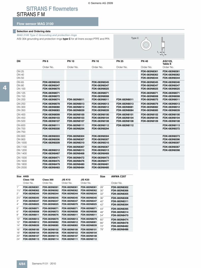
Selection and Ordering data
MAG 3100 Type C Grounding and protection rings AISI 304 grounding and protection rings type C for all liners except PTFE and PFA
DN PN 6 PN 10 PN 16 PN 25 PN 40 AS2129, Table E
Order No. Order No. Order No. Order No. Order No. Order No.
DN 25 FDK-083N8361 FDK-083N8361DN 40 FDK-083N8362 FDK-083N8362DN 50 FDK-083N8344 FDK-083N8344
DN 65 FDK-083N8345 FDK-083N8345 FDK-083N8345 FDK-083N8346DN 80 FDK-083N8347 FDK-083N8347 FDK-083N8347 FDK-083N8347DN 100 FDK-083N8070 FDK-083N8025 FDK-083N8025 FDK-083N8025
DN 125 FDK-083N8071 FDK-083N8071 FDK-083N8071 FDK-083N8071DN 150 FDK-083N8072 FDK-083N8008 FDK-083N8008 FDK-083N8008DN 200 FDK-083N8074 FDK-083N8011 FDK-083N8011 FDK-083N8011 FDK-083N8075 FDK-083N8011
DN 250 FDK-083N8078 FDK-083N8013 FDK-083N8013 FDK-083N8013 FDK-083N8079 FDK-083N8013DN 300 FDK-083N8080 FDK-083N8012 FDK-083N8012 FDK-083N8081 FDK-083N8082 FDK-083N8012DN 350 FDK-083N8083 FDK-083N8039 FDK-083N8039 FDK-083N8084 FDK-083N8085 FDK-083N8039
DN 400 FDK-083N8099 FDK-083N8100 FDK-083N8100 FDK-083N8101 FDK-083N8102 FDK-083N8100DN 450 FDK-083N8103 FDK-083N8103 FDK-083N8104 FDK-083N8104 FDK-083N8105 FDK-083N8104DN 500 FDK-083N8107 FDK-083N8107 FDK-083N8108 FDK-083N8108 FDK-083N8109 FDK-083N8108
DN 600 FDK-083N8111 FDK-083N8111 FDK-083N8112 FDK-083N8112 FDK-083N8113DN 700 FDK-083N8300 FDK-083N8294 FDK-083N8294 FDK-083N8372DN 750
DN 800 FDK-083N8303 FDK-083N8304 FDK-083N8304 FDK-083N8373DN 900 FDK-083N8306 FDK-083N8307 FDK-083N8307 FDK-083N8396DN 1000 FDK-083N8309 FDK-083N8310 FDK-083N8310 FDK-083N8397
DN 1100 FDK-083N8367 FDK-083N8367 FDK-083N8367DN 1200 FDK-083N8312 FDK-083N8313 FDK-083N8313 FDK-083N8398DN 1400 FDK-083N8467 FDK-083N8468 FDK-083N8469
DN 1500 FDK-083N8471 FDK-083N8472 FDK-083N8473DN 1600 FDK-083N8475 FDK-083N8476 FDK-083N8477DN 1800 FDK-083N8479 FDK-083N8480 FDK-083N8481DN 2000 FDK-083N8483 FDK-083N8484 FDK-083N8485
Type C
t1t2
Size ANSIClass 150 Class 300 JIS K10 JIS K20Order No. Order No. Order No. Order No.
1“ FDK-083N8361 FDK-083N8361 FDK-083N8361 FDK-083N83611½“ FDK-083N8362 FDK-083N8362 FDK-083N8362 FDK-083N83622“ FDK-083N8344 FDK-083N8344 FDK-083N8344 FDK-083N8344
2½“ FDK-083N8345 FDK-083N8345 FDK-083N8345 FDK-083N83453“ FDK-083N8347 FDK-083N8347 FDK-083N8347 FDK-083N83474“ FDK-083N8025 FDK-083N8025 FDK-083N8070 FDK-083N8025
5“ FDK-083N8071 FDK-083N8071 FDK-083N8071 FDK-083N80716“ FDK-083N8008 FDK-083N8073 FDK-083N8008 FDK-083N8008 8“ FDK-083N8011 FDK-083N8076 FDK-083N8011 FDK-083N8011
10“ FDK-083N8013 FDK-083N8079 FDK-083N8013 FDK-083N807912“ FDK-083N8012 FDK-083N8082 FDK-083N8012 FDK-083N808114“ FDK-083N8039 FDK-083N8085 FDK-083N8083 FDK-083N8039
16“ FDK-083N8100 FDK-083N8102 FDK-083N8100 FDK-083N810118“ FDK-083N8104 FDK-083N8106 FDK-083N8103 FDK-083N810420“ FDK-083N8107 FDK-083N8110 FDK-083N8107 FDK-083N810824“ FDK-083N8113 FDK-083N8114 FDK-083N8111 FDK-083N8112
Size AWWA C207
Order No.
28“ FDK-083N830230“ FDK-083N836632“ FDK-083N8305
36“ FDK-083N830840“ FDK-083N831142“ FDK-083N8394
44“ FDK-083N839548“ FDK-083N831454“ FDK-083N8470
60“ FDK-083N847466“ FDK-083N847872“ FDK-083N848278“ FDK-083N8486
© Siemens AG 2009

SITRANS F flowmetersSITRANS F M
Flow sensor MAG 3100
4/85Siemens FI 01 · 2010
4
Selection and Ordering data
MAG 3100, 3100 HT, MAG 3100 P Type E grounding and protection ring
1 pc. AISI 316 grounding and protection rings type E for PTFE liners
Note:For MAG 3100 HT High temperature version 7ME6320... for PTFE 180 °C versions. - grounding ring type E is included and factory mounted.
DN PN 6 PN 10 PN 16 PN 25 PN 40Order No. Order No. Order No. Order No. Order No.
DN 15 FDK-083N8365DN 25 FDK-083N8271DN 40 FDK-083N8278
DN 50 FDK-083N8282DN 65 FDK-083N8284 FDK-083N8285 FDK-083N8286DN 80 FDK-083N8288 FDK-083N8289 FDK-083N8290
DN 100 FDK-083N8116 FDK-083N8117 FDK-083N8118DN 125 FDK-083N8120 FDK-083N8121 FDK-083N8122DN 150 FDK-083N8124 FDK-083N8125 FDK-083N8126
DN 200 FDK-083N8129 FDK-083N8130 FDK-083N8130 FDK-083N8131 FDK-083N8132DN 250 FDK-083N8135 FDK-083N8136 FDK-083N8137 FDK-083N8138 FDK-083N8139DN 300 FDK-083N8144 FDK-083N8144 FDK-083N8145 FDK-083N8146 FDK-083N8147
DN 350 FDK-083N8152 FDK-083N8153 FDK-083N8154 FDK-083N8155 FDK-083N8156DN 400 FDK-083N8160 FDK-083N8161 FDK-083N8162 FDK-083N8163 FDK-083N8164DN 450 FDK-083N8168 FDK-083N8169 FDK-083N8170 FDK-083N8171 FDK-083N8172
DN 500 FDK-083N8177 FDK-083N8178 FDK-083N8179 FDK-083N8180 FDK-083N8181DN 600 FDK-083N8186 FDK-083N8187 FDK-083N8188 FDK-083N8189
Protection of PTFE liner use 2 pcs.Earthing of PTFE lined flowmeter use 1 pc.
Type E
t1
Size ANSI
Class 150 Class 300 JIS K10 JIS K20Order No. Order No. Order No. Order No.
½“ FDK-083N8365 FDK-083N83651“ FDK-083N8272 FDK-083N8272 FDK-083N8271 FDK-083N8271 1½“ FDK-083N8279 FDK-083N8279 FDK-083N8278 FDK-083N8278
2“ FDK-083N8283 FDK-083N8283 FDK-083N8282 FDK-083N8282 2½“ FDK-083N8287 FDK-083N8287 FDK-083N8285 FDK-083N8285 3“ FDK-083N8291 FDK-083N8292 FDK-083N8288 FDK-083N8289
4“ FDK-083N8118 FDK-083N8119 FDK-083N8116 FDK-083N81175“ FDK-083N8122 FDK-083N8123 FDK-083N8121 FDK-083N81226“ FDK-083N8126 FDK-083N8127 FDK-083N8125 FDK-083N8126
8“ FDK-083N8370 FDK-083N8133 FDK-083N8130 FDK-083N813110“ FDK-083N8140 FDK-083N8141 FDK-083N8137 FDK-083N813912“ FDK-083N8148 FDK-083N8149 FDK-083N8144 FDK-083N8146
14“ FDK-083N8157 FDK-083N8158 FDK-083N8152 FDK-083N815416“ FDK-083N8165 FDK-083N8166 FDK-083N8161 FDK-083N816318“ FDK-083N8173 FDK-083N8174 FDK-083N8169 FDK-083N8171
20“ FDK-083N8182 FDK-083N8183 FDK-083N8178 FDK-083N818024“ FDK-083N8190 FDK-083N8191 FDK-083N8187 FDK-083N8189
Protection of PTFE liner use 2 pcs.Grounding of PTFE lined flowmeter use 1 pc.
AS2129, Table EDN Order No.
DN 15 FDK-083N8365DN 25 FDK-083N8272DN 40 FDK-083N8280
DN 50 FDK-083N8281DN 65 FDK-083N8284DN 80 FDK-083N8293
DN 100 FDK-083N8117DN 125 FDK-083N8121DN 150 FDK-083N8128
DN 200 FDK-083N8134DN 250 FDK-083N8143DN 300 FDK-083N8151
DN 350 FDK-083N8153DN 400 FDK-083N8161DN 450 FDK-083N8176
DN 500 FDK-083N8185DN 600 FDK-083N8193
Protection of PTFE liner use 2 pcs.Grounding of PTFE lined flowmeter use 1 pcs.
© Siemens AG 2009
SITRANS F flowmetersSITRANS F M
Flow sensor MAG 3100
4/86 Siemens FI 01 · 2010
4
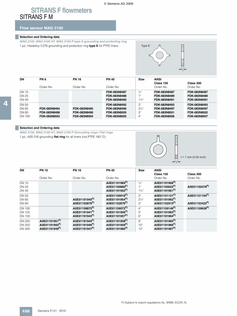
Selection and Ordering data
MAG 3100, MAG 3100 HT, MAG 3100 P type E grounding and protecting ring 1 pc. Hastelloy C276 grounding and protection ring type E for PTFE liners
DN PN 6 PN 16 PN 40 Size ANSIClass 150 Class 300
Order No. Order No. Order No. Order No. Order No.
DN 15 FDK-083N8487 ½“ FDK-083N8487 FDK-083N8487DN 25 FDK-083N8488 1“ FDK-083N8489 FDK-083N8489DN 40 FDK-083N8490 1½“ FDK-083N8491 FDK-083N8491
DN 50 FDK-083N8492 2“ FDK-083N8493 FDK-083N8493DN 65 FDK-083N8494 FDK-083N8495 FDK-083N8496 2½“ FDK-083N8497 FDK-083N8497DN 80 FDK-083N8498 FDK-083N8499 FDK-083N8500 3“ FDK-083N8501 FDK-083N8502DN 100 FDK-083N8503 FDK-083N8504 FDK-083N8505 4“ FDK-083N8506 FDK-083N8507
Type E
t1
Selection and Ordering data
MAG 3100, MAG 3100 HT, MAG 3100 P Grounding rings: Flat rings1 pc. AISI 316 grounding flat ring for all liners (not PTFE 180 ºC)
DN PN 10 PN 16 PN 40 Size ANSIClass 150 Class 300
Order No. Order No. Order No. Order No. Order No.
DN 15 A5E01191969F) ½“ A5E01191968F)
DN 25 A5E01150880F) 1“ A5E01150022F) A5E01150378F)
DN 40 A5E01191952F) 1½“ A5E01191961F)
DN 50 A5E01150918F) 2“ A5E01151121F) A5E01151194F)
DN 65 A5E01191940F) A5E01191954F) 2½“ A5E01191962F)
DN 80 A5E01152876F) A5E01152876F) 3“ A5E01152910F) A5E01153422F)
DN 100 A5E01158875F) A5E01159072F) 4“ A5E01159146F) A5E01159628F)
DN 125 A5E01191941F) A5E01191956F) 5“ A5E01191963F)
DN 150 A5E01191943F) A5E01191957F) 6“ A5E01191964F)
DN 200 A5E01191951F) A5E01191944F) A5E01191958F) 8“ A5E01191965F)
DN 250 A5E01191950F) A5E01191946F) A5E01191959F) 10“ A5E01191966F)
DN 300 A5E01191949F) A5E01191947F) A5E01191960F) 12“ A5E01191967F)
t = 1 mm (0.04 inch)
t
F) Subject to export regulations AL: 9I999, ECCN: N.
© Siemens AG 2009
SITRANS F flowmetersSITRANS F M
Flow sensor MAG 3100
4/87Siemens FI 01 · 2010
4
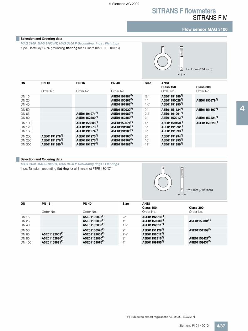
Selection and Ordering data
MAG 3100, MAG 3100 HT, MAG 3100 P Grounding rings : Flat rings1 pc. Hastelloy C276 grounding flat ring for all liners (not PTFE 180 ºC)
DN PN 10 PN 16 PN 40 Size ANSIClass 150 Class 300
Order No. Order No. Order No. Order No. Order No.
DN 15 A5E01191981F) ½“ A5E01191989F)
DN 25 A5E01150882F) 1“ A5E01150028F) A5E01150379F)
DN 40 A5E01191982F) 1½“ A5E01191990F)
DN 50 A5E01150922F) 2“ A5E01151124F) A5E01151197F)
DN 65 A5E01191971F) A5E01191983F) 2½“ A5E01191991F)
DN 80 A5E01152889F) A5E01152889F) 3“ A5E01152913F) A5E01153424F)
DN 100 A5E01158886F) A5E01159074F) 4“ A5E01159150F) A5E01159629F)
DN 125 A5E01191973F) A5E01191984F) 5“ A5E01191992F)
DN 150 A5E01191974F) A5E01191985F) 6“ A5E01191993F)
DN 200 A5E01191978F) A5E01191975F) A5E01191986F) 8“ A5E01191994F)
DN 250 A5E01191979F) A5E01191976F) A5E01191987F) 10“ A5E01191995F)
DN 300 A5E01191980F) A5E01191977F) A5E01191988F) 12“ A5E01191996F)
t = 1 mm (0.04 inch)
t
Selection and Ordering data
MAG 3100, MAG 3100 HT, MAG 3100 P Grounding rings : Flat rings1 pc. Tantalum grounding flat ring for all liners (not PTFE 180 ºC)
DN PN 16 PN 40 Size ANSIClass 150 Class 300
Order No. Order No. Order No. Order No.
DN 15 A5E01192007F) ½“ A5E01192010F)
DN 25 A5E01150883F) 1“ A5E01150030F) A5E01150381F)
DN 40 A5E01192008F) 1½“ A5E01192011F)
DN 50 A5E01150926F) 2“ A5E01151129F) A5E01151199F)
DN 65 A5E01192005F) A5E01192009F) 2½“ A5E01192012F)
DN 80 A5E01152890F) A5E01152890F) 3“ A5E01152916F) A5E01153427F)
DN 100 A5E01158891F) A5E01159076F) 4“ A5E01159156F) A5E01159631F)
t = 1 mm (0.04 inch)
t
F) Subject to export regulations AL: 9I999, ECCN: N.
© Siemens AG 2009
SITRANS F flowmetersSITRANS F M
Flow sensor MAG 3100
4/88 Siemens FI 01 · 2010
4
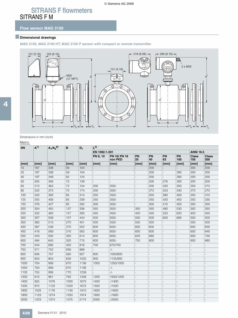
■ Dimensional drawings
MAG 3100, MAG 3100 HT, MAG 3100 P sensor with compact or remote transmitter
Dimensions in mm (inch)
Metric
A1
155 (6.10)
LB
CT
131 (5.16)
D1
M20 (½"�NPT)
2A
TELB
D1
TC
208 (8.19)218 (8.58)
2 x M25
TE D
A
131 (5.16)
DN A1) A1/A28) B D1 L2)
EN 1092-1-201 ANSI 16.5PN 6, 10 PN 16/ PN 16
non PEDPN25
PN40
PN63
PN100
Class150
Class300
[mm] [mm] [mm] [mm] [mm] [mm] [mm] [mm] [mm] [mm] [mm] [mm] [mm]15 187 338 59 104 - - - 200 - - 200 200
25 187 338 59 104 - - - 200 - 260 200 200
40 197 348 82 124 - - - 200 - 280 200 200
50 205 356 72 139 - - - 200 276 300 200 200
65 212 363 72 154 200 200/- - 200 320 350 200 272
80 222 373 72 174 200 200/- - 272 323 340 272 272
100 242 393 85 214 250 250/- - 250 380 400 250 310
125 255 406 85 239 250 250/- - 250 420 450 250 335
150 276 427 85 282 300 300/- - 300 415 450 300 300
200 304 455 137 338 350 350/- 350 350 480 530 350 350
250 332 483 157 393 450 450/- 450 450 550 620 450 450
300 357 508 157 444 500 500/- 500 500 600 680 500 500
350 362 513 270 451 550 550/- 550 550 - - 550 550
400 387 538 270 502 600 600/- 600 600 - - 600 600
450 418 569 310 563 600 600/- 600 600 - - 600 640
500 443 594 350 614 600 600/- 625 680 - - 600 730
600 494 645 320 715 600 600/- 750 800 - - 600 860
700 544 695 450 816 700 875/700 - - - - - -
750 571 722 556 869 - -/- - - - - - -
800 606 757 560 927 800 1000/800 - - - - - -
900 653 804 630 1032 900 1125/900 - - - - - -
1000 704 906 670 1136 1000 1250/1000 - - - - - -
1050 704 906 670 1136 - -/- - - - - - -
1100 755 906 770 1238 - -/- - - - - - -
1200 810 961 792 1348 1200 1500/1200 - - - - - -
1400 925 1076 1000 1675 1400 -/1400 - - - - - -
1500 972 1123 1020 1672 1500 -/1500 - - - - - -
1600 1025 1176 1130 1915 1600 -/1600 - - - - - -
1800 1123 1274 1250 1974 1800 -/1800 - - - - - -
2000 1223 1374 1375 2174 2000 -/2000 - - - - - -
© Siemens AG 2009
SITRANS F flowmetersSITRANS F M
Flow sensor MAG 3100
4/89Siemens FI 01 · 2010
4
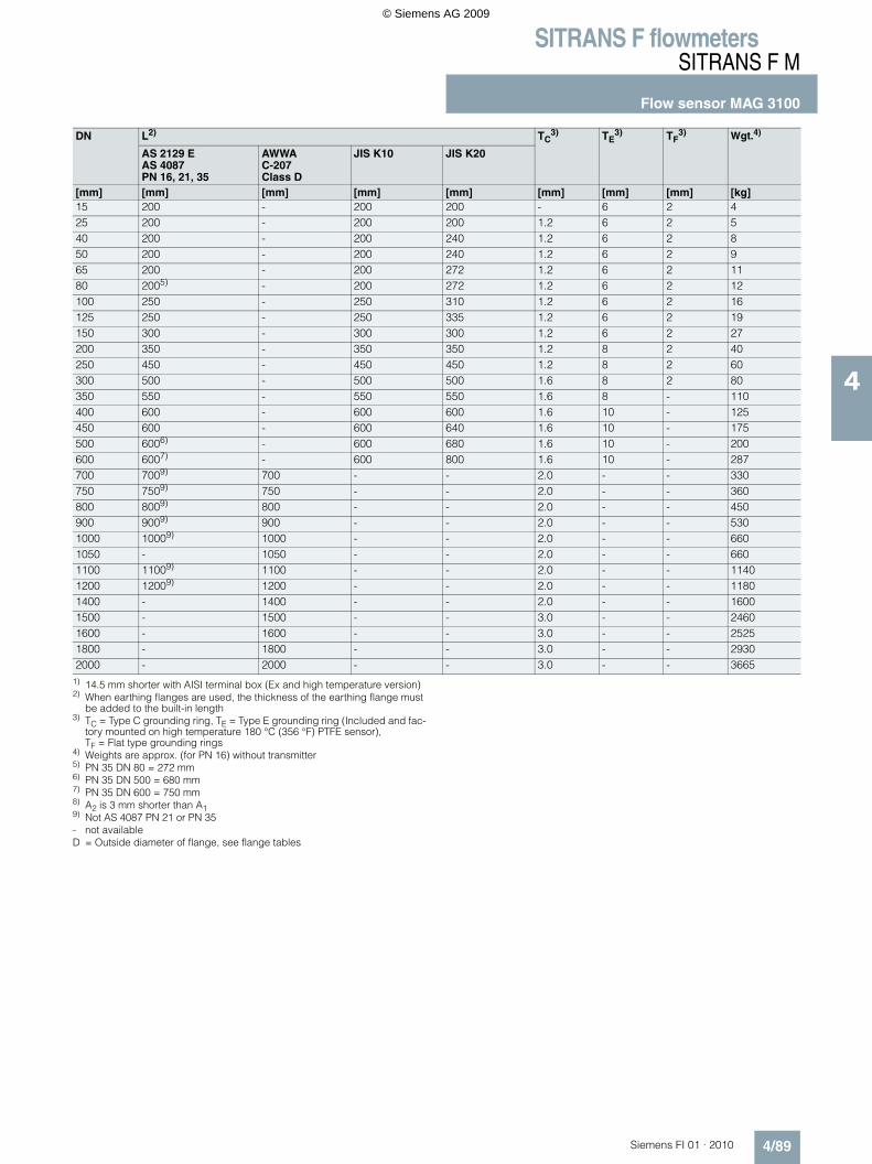
1) 14.5 mm shorter with AISI terminal box (Ex and high temperature version)2) When earthing flanges are used, the thickness of the earthing flange must
be added to the built-in length3) TC = Type C grounding ring, TE = Type E grounding ring (Included and fac-
tory mounted on high temperature 180 °C (356 °F) PTFE sensor),TF = Flat type grounding rings
4) Weights are approx. (for PN 16) without transmitter5) PN 35 DN 80 = 272 mm6) PN 35 DN 500 = 680 mm7) PN 35 DN 600 = 750 mm8) A2 is 3 mm shorter than A19) Not AS 4087 PN 21 or PN 35- not availableD = Outside diameter of flange, see flange tables
DN L2) TC3) TE
3) TF3) Wgt.4)
AS 2129 EAS 4087PN 16, 21, 35
AWWAC-207Class D
JIS K10 JIS K20
[mm] [mm] [mm] [mm] [mm] [mm] [mm] [mm] [kg]15 200 - 200 200 - 6 2 425 200 - 200 200 1.2 6 2 540 200 - 200 240 1.2 6 2 850 200 - 200 240 1.2 6 2 965 200 - 200 272 1.2 6 2 1180 2005) - 200 272 1.2 6 2 12100 250 - 250 310 1.2 6 2 16125 250 - 250 335 1.2 6 2 19150 300 - 300 300 1.2 6 2 27200 350 - 350 350 1.2 8 2 40250 450 - 450 450 1.2 8 2 60300 500 - 500 500 1.6 8 2 80350 550 - 550 550 1.6 8 - 110400 600 - 600 600 1.6 10 - 125450 600 - 600 640 1.6 10 - 175500 6006) - 600 680 1.6 10 - 200600 6007) - 600 800 1.6 10 - 287700 7009) 700 - - 2.0 - - 330750 7509) 750 - - 2.0 - - 360800 8009) 800 - - 2.0 - - 450900 9009) 900 - - 2.0 - - 5301000 10009) 1000 - - 2.0 - - 6601050 - 1050 - - 2.0 - - 6601100 11009) 1100 - - 2.0 - - 11401200 12009) 1200 - - 2.0 - - 11801400 - 1400 - - 2.0 - - 16001500 - 1500 - - 3.0 - - 24601600 - 1600 - - 3.0 - - 25251800 - 1800 - - 3.0 - - 29302000 - 2000 - - 3.0 - - 3665
© Siemens AG 2009

SITRANS F flowmetersSITRANS F M
Flow sensor MAG 3100
4/90 Siemens FI 01 · 2010
4
MAG 3100, MAG 3100 HT, MAG 3100 P sensor with compact or remote transmitter
Imperial
Size A1) A1/A28) B D1 L2)
EN 1092-1-201 ANSI 16.5
PN 6, 10 PN 16/ PN 16 non PED
PN25
PN40
PN63
PN100
Class150
Class300
[in.] [inch] [inch] [inch] [inch] [inch] [inch] [inch] [inch] [inch] [inch] [inch] [inch]
½ 7.36 13.31 2.32 4.09 - - - 7.87 - - 7.87 7.87
1 7.36 13.31 2.32 4.09 - - - 7.87 - 10.24 7.87 7.87
1½ 7.76 13.70 3.23 4.88 - - - 7.87 - 11.02 7.87 7.87
2 8.07 14.01 2.83 5.47 - - - 7.87 10.87 11.81 7.87 7.87
2½ 8.35 14.29 2.83 6.06 7.87 7.87/- - 7.87 12.60 13.78 7.87 10.71
3 8.74 14.69 2.83 6.85 7.87 7.87/- - 10.71 12.72 13.39 10.71 10.71
4 9.53 15.47 3.35 8.43 9.84 9.84/- - 9.84 14.96 - 9.84 12.20
5 10.04 15.98 3.35 9.41 9.84 9.84/- - 9.84 16.54 - 9.84 13.10
6 10.87 16.81 5.39 11.10 11.81 11.81/- - 11.81 16.34 - 11.81 11.81
8 11.97 17.91 5.39 13.31 13.78 13.78/- 13.78 13.78 18.90 - 13.78 13.78
10 13.07 19.02 6.18 15.47 17.72 17.72/- 17.72 17.72 - - 17.72 17.72
12 14.05 20.00 6.18 17.48 19.69 19.69/- 19.69 19.69 - - 19.69 19.69
14 14.25 20.20 10.63 17.76 21.65 21.65/- 21.65 21.65 - - 21.65 21.65
16 15.24 21.18 10.63 19.76 23.62 23.62/- 23.62 23.62 - - 23.62 23.62
18 16.45 22.40 12.20 22.16 23.62 23.62/- 23.62 23.62 - - 23.62 23.62
20 17.44 23.39 13.78 24.17 23.62 23.62/- 24.61 26.77 - - 23.62 28.70
24 19.45 25.39 12.59 28.15 23.62 23.62/- 29.53 31.50 - - 23.62 33.80
28 21.42 27.36 17.72 32.13 27.56 34.45/27.56 - - - - - -
30 22.48 28.43 21.89 34.21 - -/- - - - - - -
32 23.86 29.80 22.05 36.50 31.50 39.37/31.50 - - - - - -
36 25.71 31.65 24.80 40.63 35.43 44.29/35.43 - - - - - -
40 27.72 35.67 26.38 44.72 39.37 49.21/39.37 - - - - - -
42 27.72 35.67 26.38 44.72 - -/- - - - - - -
44 29.72 35.67 30.31 48.74 - -/- - - - - - -
48 31.89 37.83 31.18 53.07 47.24 59.06/47.24 - - - - - -
54 36.42 42.36 39.37 65.94 55.12 -/55.12 - - - - - -
60 38.27 44.21 40.15 65.83 59.06 59.06/59.06 - - - - - -
66 40.35 46.30 44.49 75.39 62.99 -/62.99 - - - - - -
72 44.21 50.16 49.21 77.72 70.87 -/70.87 - - - - - -
78 48.15 54.09 54.13 85.59 78.74 -/78.74 - - - - - -
© Siemens AG 2009

SITRANS F flowmetersSITRANS F M
Flow sensor MAG 3100
4/91Siemens FI 01 · 2010
4
1) 0.571 inch shorter with AISI terminal box (Ex and high temperature version)2) When earthing flanges are used, the thickness of the earthing flange must be added to the built-in length3) TC = Type C grounding ring, TE = Type E grounding ring (Included and factory mounted on high temperature 180 °C (356 °F) PTFE sensor),
TF = Flat type grounding rings4) Weights are for ANSI 150 without transmitter5) PN 35 DN 80 = 10.70 inch6) PN 35 DN 500 = 26.77 inch7) PN 35 DN 600 = 29.53 inch8) A2 is 0.06“ shorter than A1- not availableD = Outside diameter of flange, see flange tables
Size L2) TC3) TE
3) TF3) Wgt.4)
AS 2129 EAS 4087PN 16, 21, 35
AWWAC-207Class D
JIS K10 JIS K20
[in.] [inch] [inch] [inch] [inch] [in.] [in.] [in.] [lb]
½ 7.87 - 7.87 7.87 - 0.24 0.08 9
1 7.87 - 7.87 7.87 0.05 0.24 0.08 11
1½ 7.87 - 7.87 9.44 0.05 0.24 0.08 17
2 7.87 - 7.87 9.44 0.05 0.24 0.08 20
2½ 7.87 - 7.87 10.70 0.05 0.24 0.08 24
3 7.875) - 7.87 10.70 0.05 0.24 0.08 26
4 9.84 - 9.84 12.20 0.05 0.24 0.08 35
5 9.84 - 9.84 13.18 0.05 0.24 0.08 42
6 11.81 - 11.81 11.81 0.05 0.24 0.08 60
8 13.78 - 13.77 13.77 0.05 0.31 0.08 88
10 17.72 - 17.71 17.71 0.05 0.31 0.08 132
12 19.69 - 19.68 19.68 0.06 0.31 0.08 176
14 21.65 - 21.65 21.65 0.06 0.31 - 242
16 23.62 - 23.62 23.62 0.06 0.39 - 275
18 23.62 - 23.62 25.19 0.06 0.39 - 385
20 23.626) - 23.62 26.77 0.06 0.39 - 440
24 23.627) - 23.62 31.49 0.06 0.39 - 633
28 27.56 27.56 0.08 - - 728
30 - 29.52 0.08 - - 794
32 31.50 31.50 0.08 - - 992
36 35.43 35.43 0.08 - - 1168
40 39.37 39.37 0.08 - - 1455
42 - 39.37 0.08 - - 1455
44 43.31 43.31 0.08 - - 2513
48 47.24 47.24 0.08 - - 2601
54 - 55.12 0.12 - - 3528
60 - 59.06 0.12 - - 5423
66 - 63.00 0.12 - - 5566
72 - 70.87 0.12 - - 6460
78 - 78.74 0.12 - - 8080
© Siemens AG 2009