Embed Size (px)
Citation preview
ZiLOG Worldwide HTelephone:
ZHX1201
SIR UltraSlimTM Transceiver (IrMC)
Preliminary Product SpecificationPS015207-0104
eadquarters • 532 Race Street • San Jose, CA 95126-3432408.558.8500 • Fax: 408.558.8300 • www.ZiLOG.com

P R E L I M I N A R Y PS015207-0104
This publication is subject to replacement by a later edition. To determine whether a later edition exists, or to request copies of publications, contact:
ZiLOG Worldwide Headquarters532 Race StreetSan Jose, CA 95126-3432Telephone: 408.558.8500Fax: 408.558.8300www.ZiLOG.com
ZiLOG is a registered trademark of ZiLOG Inc. in the United States and in other countries. All other products and/or service names mentioned herein may be trademarks of the companies with which they are associated.
Document Disclaimer©2004 by ZiLOG, Inc. All rights reserved. Information in this publication concerning the devices, applications, or technology described is intended to suggest possible uses and may be superseded. ZiLOG, INC. DOES NOT ASSUME LIABILITY FOR OR PROVIDE A REPRESENTATION OF ACCURACY OF THE INFORMATION, DEVICES, OR TECHNOLOGY DESCRIBED IN THIS DOCUMENT. ZiLOG ALSO DOES NOT ASSUME LIABILITY FOR INTELLECTUAL PROPERTY INFRINGEMENT RELATED IN ANY MANNER TO USE OF INFORMATION, DEVICES, OR TECHNOLOGY DESCRIBED HEREIN OR OTHERWISE. Devices sold by ZiLOG, Inc. are covered by warranty and limitation of liability provisions appearing in the ZiLOG, Inc. Terms and Conditions of Sale. ZiLOG, Inc. makes no warranty of merchantability or fitness for any purpose. Except with the express written approval of ZiLOG, use of information, devices, or technology as critical components of life support systems is not authorized. No licenses are conveyed, implicitly or otherwise, by this document under any intellectual property rights.
ZHX1201SIR UltraSlim Transceiver (IrMC)
iii
Table of ContentsDescription . . . . . . . . . . . . . . . . . . . . . . . . . . . . . . . . . . . . . . . . . . . . . . . . . . . . . 1
Features . . . . . . . . . . . . . . . . . . . . . . . . . . . . . . . . . . . . . . . . . . . . . . . . . . . . . . . 2
Pin Description . . . . . . . . . . . . . . . . . . . . . . . . . . . . . . . . . . . . . . . . . . . . . . . . . . 2VCC Positive Supply . . . . . . . . . . . . . . . . . . . . . . . . . . . . . . . . . . . . . . . . . . . 2GND Ground . . . . . . . . . . . . . . . . . . . . . . . . . . . . . . . . . . . . . . . . . . . . . . . . . 3SD Shutdown . . . . . . . . . . . . . . . . . . . . . . . . . . . . . . . . . . . . . . . . . . . . . . . . 3RxD Receive Data . . . . . . . . . . . . . . . . . . . . . . . . . . . . . . . . . . . . . . . . . . . . . 3TxD Transmit Data . . . . . . . . . . . . . . . . . . . . . . . . . . . . . . . . . . . . . . . . . . . . 3LEDA LED Driver . . . . . . . . . . . . . . . . . . . . . . . . . . . . . . . . . . . . . . . . . . . . . 3TAB Shield Connection . . . . . . . . . . . . . . . . . . . . . . . . . . . . . . . . . . . . . . . . . 3
Application Block Diagrams . . . . . . . . . . . . . . . . . . . . . . . . . . . . . . . . . . . . . . . . . 4
Electrical and Timing Specifications . . . . . . . . . . . . . . . . . . . . . . . . . . . . . . . . . . 5
ZHX1201 Tape and Reel Specifications . . . . . . . . . . . . . . . . . . . . . . . . . . . . . . . 7
ZHX1201 Soldering and Cleaning Recommendations . . . . . . . . . . . . . . . . . . . . 8Reflow Soldering . . . . . . . . . . . . . . . . . . . . . . . . . . . . . . . . . . . . . . . . . . . . . . 8Manual Soldering . . . . . . . . . . . . . . . . . . . . . . . . . . . . . . . . . . . . . . . . . . . . . 8Cleaning . . . . . . . . . . . . . . . . . . . . . . . . . . . . . . . . . . . . . . . . . . . . . . . . . . . . 8
Moisture Prevention Guidelines . . . . . . . . . . . . . . . . . . . . . . . . . . . . . . . . . . . . . 9
Baking . . . . . . . . . . . . . . . . . . . . . . . . . . . . . . . . . . . . . . . . . . . . . . . . . . . . . . . . . 9
Mechanical Drawing . . . . . . . . . . . . . . . . . . . . . . . . . . . . . . . . . . . . . . . . . . . . . 10
Ordering Information . . . . . . . . . . . . . . . . . . . . . . . . . . . . . . . . . . . . . . . . . . . . . 11
Customer Feedback Form . . . . . . . . . . . . . . . . . . . . . . . . . . . . . . . . . . . . . . . . . 11Customer Information . . . . . . . . . . . . . . . . . . . . . . . . . . . . . . . . . . . . . . . . . 11Product Information . . . . . . . . . . . . . . . . . . . . . . . . . . . . . . . . . . . . . . . . . . . 11Return Information . . . . . . . . . . . . . . . . . . . . . . . . . . . . . . . . . . . . . . . . . . . . 11Problem Description or Suggestion . . . . . . . . . . . . . . . . . . . . . . . . . . . . . . . 11
PS015207-0104 P R E L I M I N A R Y
ZHX1201SIR UltraSlim Transceiver (IrMC)
iv
List of FiguresFigure 1. UltraSlim Form . . . . . . . . . . . . . . . . . . . . . . . . . . . . . . . . . . . . . . . . . . 1Figure 2. ZHX1201 Block Diagram . . . . . . . . . . . . . . . . . . . . . . . . . . . . . . . . . . 1Figure 3. ZHX1201 Application Block Diagrams . . . . . . . . . . . . . . . . . . . . . . . . 4Figure 4. ZHX1201 Reel Specifications . . . . . . . . . . . . . . . . . . . . . . . . . . . . . . 7Figure 5. ZHX1201 Tape Specifications . . . . . . . . . . . . . . . . . . . . . . . . . . . . . . 7Figure 6. Temperature Profile for the Top Surface . . . . . . . . . . . . . . . . . . . . . . 8Figure 7. ZHX1201 Packaging . . . . . . . . . . . . . . . . . . . . . . . . . . . . . . . . . . . . . 9Figure 8. ZHX1201 Mechanical Drawing . . . . . . . . . . . . . . . . . . . . . . . . . . . . 10
List of TablesTable 1. ZHX1201 Transceiver Pin Out . . . . . . . . . . . . . . . . . . . . . . . . . . . . . . 2Table 2. Absolute Maximum Ratings . . . . . . . . . . . . . . . . . . . . . . . . . . . . . . . . 5Table 3. Recommended Operating Conditions . . . . . . . . . . . . . . . . . . . . . . . . 5Table 4. Electrical Characteristics . . . . . . . . . . . . . . . . . . . . . . . . . . . . . . . . . . 5
PS015207-0104 P R E L I M I N A R Y

ZHX1201SIR UltraSlim Transceiver (IrMC)
1
DescriptionThe ZILOG ZHX1201 for mobile phones, pagers, and PDAs is a small, low power, and high functionality transceiver.
ZiLOG’s low-power CMOS technology allows the transceiver to receive an IrDA communication at a typical current of 100 µA.
The UltraSlim form factor (8 mm long x 3 mm wide x 2.5 mm high) allows place-ment in many small devices (see Figure 1). Application circuit space is also mini-mized because only one external component is required.
Figure 1. UltraSlim Form
The ZHX1201 is designed to support IrDA-Data SIR mode, which at 115 Kbits/s provides the capability for the user to share phone numbers, addresses, and notes as well as linking a PC to the internet via a mobile telephone.
The transceiver combines an IRED emitter, a PIN photodiode, and a unique driver/control ASIC in a single package, as shown in Figure 2.
Figure 2. ZHX1201 Block Diagram
The ZILOG ZHX1201 also features a shutdown control that minimizes current draw to 0.1 µA typical.
PS015207-0104 P R E L I M I N A R Y

ZHX1201SIR UltraSlim Transceiver (IrMC)
2
Features• Compliant to IrDA Data Specification 1.4 Low Power SIR (link range: low
power to low power—0 to 20 cm; standard power to low power—0 to 30 cm)
• Low-power supply voltage range: 2.4 to 3.6 V
• Receiving current: only 100 µA (typically) at 3.0 V
• UltraSlim package: 8 mm long x 3 mm wide x 2.5 mm high
• Extended operating temperature range: –30 ºC to +85 ºC
• Internal current source eliminates current limiting resistor
• Meets IEC 825-1 Class 1 eye safety specifications
Pin DescriptionTable 1 lists the pin out for the ZHX1201 transceiver. The pins are described in this section.
VCC Positive Supply (Power)
Connect to positive power supply (2.4–3.6 V). Filter with a 1.0 µF ceramic bypass capacitor and terminating resistor as close as possible to the VCC pin.
Table 1. ZHX1201 Transceiver Pin Out
Pin Name Function I/O
1 GND Ground —
2 NC NC
3 VCC Supply voltage —
4 GND Ground —
5 SD Shutdown I
6 RxD Receiver output O
7 TxD Transmitter input I
8 LEDA IRED anode —
— TAB Shield connection —
PS015207-0104 P R E L I M I N A R Y
ZHX1201SIR UltraSlim Transceiver (IrMC)
3
GND Ground (Power)
Connect to ground of the power supply. A solid ground plane is recommended for proper operation.
SD Shutdown(Input, active high)
This input is used to place the IC into a shutdown mode.
TxD needs to be driven low to achieve low shutdown current and held low during the transition from shutdown to active to ensure that the circuitry is properly set to communicate.
RxD Receive Data (Output, active low)
This output provides received serial data. It is a tri-state, slew rate controlled CMOS output (tri-stated during shutdown) driver capable of driving a standard CMOS or LS series TTL load. No external resistor is required.
TxD Transmit Data (Input, active high)
This CMOS input is used to transmit serial data and has an internal pull-down resistor that is disabled (open-circuited) during shutdown. With integrated digital AC coupling, no external components are required for input signals between GND and VCC.
LEDA LED Driver(Power)
This output is internally connected to the LED anode and contains an internal current source. The voltage range on this pad is 2.4–4.2 volts.
TAB Shield ConnectionThe shield tab must be soldered to ground for proper operation.
PS015207-0104 P R E L I M I N A R Y
ZHX1201SIR UltraSlim Transceiver (IrMC)
4
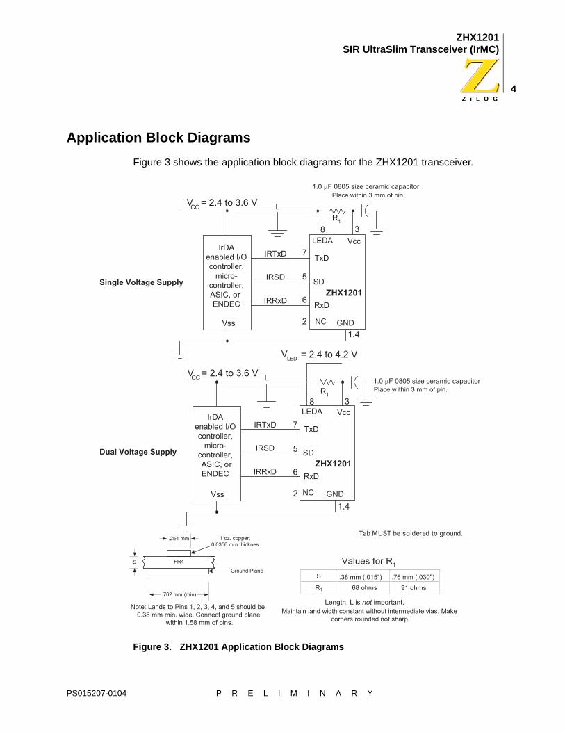
Application Block DiagramsFigure 3 shows the application block diagrams for the ZHX1201 transceiver.
Figure 3. ZHX1201 Application Block Diagrams
PS015207-0104 P R E L I M I N A R Y
ZHX1201SIR UltraSlim Transceiver (IrMC)
5
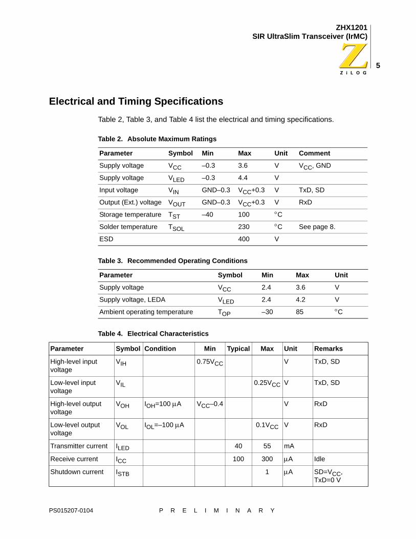
Electrical and Timing SpecificationsTable 2, Table 3, and Table 4 list the electrical and timing specifications.
Table 2. Absolute Maximum Ratings
Parameter Symbol Min Max Unit Comment
Supply voltage VCC –0.3 3.6 V VCC, GND
Supply voltage VLED –0.3 4.4 V
Input voltage VIN GND–0.3 VCC+0.3 V TxD, SD
Output (Ext.) voltage VOUT GND–0.3 VCC+0.3 V RxD
Storage temperature TST –40 100 °C
Solder temperature TSOL 230 °C See page 8.
ESD 400 V
Table 3. Recommended Operating Conditions
Parameter Symbol Min Max Unit
Supply voltage VCC 2.4 3.6 V
Supply voltage, LEDA VLED 2.4 4.2 V
Ambient operating temperature TOP –30 85 °C
Table 4. Electrical Characteristics
Parameter Symbol Condition Min Typical Max Unit Remarks
High-level input voltage
VIH 0.75VCC V TxD, SD
Low-level input voltage
VIL 0.25VCC V TxD, SD
High-level output voltage
VOH IOH=100 µA VCC–0.4 V RxD
Low-level output voltage
VOL IOL=–100 µA 0.1VCC V RxD
Transmitter current ILED 40 55 mA
Receive current ICC 100 300 µA Idle
Shutdown current ISTB 1 µA SD=VCC, TxD=0 V
PS015207-0104 P R E L I M I N A R Y

ZHX1201SIR UltraSlim Transceiver (IrMC)
6
This component is susceptible to damage from electrostatic discharge (ESD). To prevent damage and/or degradation that might be induced by ESD, use normal static precautions in handling and assembly of this component.
TxD must be held low during the transition from shutdown to active to ensure that the circuitry is properly set to communicate.
RxD rise/fall time TR, TF Cload=25 pF 40 100 ns 10% and 90%
RxD pulse width tPWA SIR<115.2 Kbps 1.0 5 µs Input pulse=1.6 µs; rise/fall time<600 ns
RxD pulse width, alternate 3/16th of pulse duration. See IrDA Physical Layer specs.
tPWA SIR<115.2 Kbps 1.2 90 µs Input pulse=78 µs (3/16*(1/2400))
Power shutdown time
TSD 0.1 200 µs
Startup time TSTU 200 µs
Latency TRRT 150 µs
LED protection timeout
105 180 270 µs Protects LED when TxD is left high
Trans. radiant intensity
IE ILED=40 mA 3.6 72 mW/sr θh, θv<(+15°)
Threshold irradiance Eemin VCC=3.3 V 9 µW/cm2 θh, θv<(+15°)
Input irradiance Eemax VCC=3.3 V 500 mW/cm2 θh, θv<(+15°)
Angle of half intensity
θ 20 ° Hor. and vert.
Peak wavelength λρ 870 nm
Unless otherwise noted: VCC=3.3 V, GND=0 V, TA=25 °C
Table 4. Electrical Characteristics (Continued)
Parameter Symbol Condition Min Typical Max Unit Remarks
Caution:
Note:
PS015207-0104 P R E L I M I N A R Y

ZHX1201SIR UltraSlim Transceiver (IrMC)
7
ZHX1201 Tape and Reel SpecificationsFigure 4 shows the ZHX1201 reel specifications, and Figure 5 shows the ZHX1201 tape specifications.
Figure 4. ZHX1201 Reel Specifications
Figure 5. ZHX1201 Tape Specifications
-
-
-
-
-
-
PS015207-0104 P R E L I M I N A R Y

ZHX1201SIR UltraSlim Transceiver (IrMC)
8
ZHX1201 Soldering and Cleaning RecommendationsFollow these recommendations to maintain the performance of the ZHX1201 transceiver.
Reflow Soldering• Reflow soldering paste is recommended.
• Preheat: 120~150 °C, 60 to 120 seconds
• Heating up and cooling down: 5 °C/second
• Maximum number of reflows: 2
• The temperature profile at the top surface of the ZHX1201 transceiver, shown in Figure 6, is recommended.
Figure 6. Temperature Profile for the Top Surface
Manual Soldering• Use 63/37 or silver solder.
• Temperature at solder iron tip: no more than 280 °C
• Finish soldering within 3 seconds.
• Handle only after ZHX1201 has cooled off.
CleaningPerform cleaning under the following conditions:
• Cleaning agent: alcohol
• Temperature and time 30 seconds below 50 °C or 3 minutes below 30 °C
• Ultrasonic cleaning: below 20 W
PS015207-0104 P R E L I M I N A R Y
ZHX1201SIR UltraSlim Transceiver (IrMC)
9
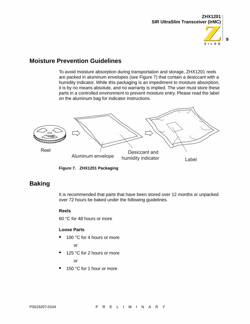
Moisture Prevention GuidelinesTo avoid moisture absorption during transportation and storage, ZHX1201 reels are packed in aluminum envelopes (see Figure 7) that contain a desiccant with a humidity indicator. While this packaging is an impediment to moisture absorption, it is by no means absolute, and no warranty is implied. The user must store these parts in a controlled environment to prevent moisture entry. Please read the label on the aluminum bag for indicator instructions.
Figure 7. ZHX1201 Packaging
BakingIt is recommended that parts that have been stored over 12 months or unpacked over 72 hours be baked under the following guidelines.
Reels60 °C for 48 hours or more
Loose Parts• 100 °C for 4 hours or more
or
• 125 °C for 2 hours or more
or
• 150 °C for 1 hour or more
PS015207-0104 P R E L I M I N A R Y

ZHX1201SIR UltraSlim Transceiver (IrMC)
10
Mechanical DrawingFigure 8 shows the mechanical specification for the ZHX1201 transceiver.
Figure 8. ZHX1201 Mechanical Drawing
PS015207-0104 P R E L I M I N A R Y
ZHX1201SIR UltraSlim Transceiver (IrMC)
11
Ordering InformationUse the following information to order the ZHX1201 transceiver:
Customer Feedback FormIf you experience any problems while operating this product, or if you note any inaccura-cies while reading this product specification, please copy and complete this form, then mail or fax it to ZiLOG (see Return Information, below). We also welcome your sugges-tions!
Customer Information
Product Information
Return InformationZiLOGSystem Test/Customer Support532 Race StreetSan Jose, CA 95126-3432Fax: (408) 558-8300Customer Service: www.zilog.com
Problem Description or SuggestionProvide a complete description of the problem or your suggestion. If you are reporting a specific problem, include all steps leading up to the occurrence of the problem. Attach additional pages as necessary.
ZHX1201MB115THTR 2500 per reel
Name CountryCompany PhoneAddress FaxCity/State/Zip email
Serial # or Board Fab #/Rev #Software VersionDocument NumberHost Computer Description/Type
PS015207-0104 P R E L I M I N A R Y