Embed Size (px)
Citation preview

SIMULATIONS FOR THE SNS LINAC
A. Shishlo# on behalf of SNS Accelerator Group, ORNL, Oak Ridge, TN 37831, U.S.A.
Abstract Review of the simulations tools used for the Spallation
Neutron Source (SNS) linac tuning and beam dynamics studies is presented. The usage and comparison of the different approaches like single-particle, envelope, particle-in-cell and codes for particular tasks is discussed. The codes considered include Parmila, Impact, Track, and XAL online model. Future code development for the SNS linac is suggested.
INTRODUCTION Usually there are varieties of computer simulation
codes that are used during different stages of a machine history: design, commissioning, tuning, production etc. Different codes can be used to analyze different aspects of beam physics or to verify results from other codes. The SNS linac is not an exception. This paper discusses computer codes that were used for the SNS during its more than 10 years of transformation from design to operational machine.
SNS LINAC The SNS linac consists of two structures which are a
normal temperature and super-conducting (SCL) linac. The normal-conducting section (accelerating the beam up to 185 MeV) includes a Low-Energy Beam Transfer (LEBT) line downstream of the H- ion source leading to a 2.5 MeV RFQ, a Medium-Energy Beam Transfer (MEBT) line, a 402.5-MHz drift tube linac (DTL), followed by a 805-MHz coupled cavity linac (CCL). The SRF structure accelerates the beam from a nominal energy of 185 MeV to 1000 MeV. The SCL section consists of two sections: a low beta (βg = 0.61) and a high beta (βg = 0.81).
The two parts (room temperature and super-conducting) of the linac are quite different from the beam dynamics point of view. The RF gap phases and longitudinal beam dynamics in the normal conducting sections were defined at the design stage. The purpose of the tuning process is to reproduce the design settings in the real structures. In contrast, the amplitudes and phases of the SCL cavities can be changed in a wide range, and the performance of SCL should not suffer from this [1]. As a result the tuning procedures should different for these parts of the SNS linac.
In the design of the SNS linac measures were taken to avoid halo generation and, therefore, to minimize beam losses [2]. The measures include: the zero-current phase advances (transverse and longitudinal) per period never exceed 900; transverse and longitudinal phase advances do not cross to avoid the second order parametric resonance, except in DTL tank 1 and CCL module 4
where matching considerations prevail; transverse and longitudinal phase advances per meter are smooth functions along the linac to provide a current independent design.
The nominal peak current in the SNS linac is 38 mA, and space charge effects are expected to be significant for the beam dynamics [2].
COMPUTER CODES The following computer simulation codes were and are
being used at SNS • XAL online model (OM) [3] is a part of the XAL
application programming framework developed at SNS [4]. The online model has both envelope and single particle tracking capabilities. The tracking algorithms were borrowed from TRACE 3-D (space charge) and PARMILA (RF gaps). The online model was thoroughly benchmarked against both these codes. The XAL OM is a base for dozens of XAL applications used for SNS linac tune up and offline analysis.
• TRACE 3-D is a beam-dynamics program that tracks the envelopes of a bunched beam through a user-defined transport system [5]. The space charge calculations are included as linear forces. It was used for fast beam dynamics calculations during the early stages of the SNS project.
• PARMILA (Phase and Radial Motion in Ion Linear Accelerators) is a computer code used for the design and simulation of proton and heavy ion linear accelerators [6]. The SNS linac was designed on the basis of PARMILA simulations. PARMILA’s algorithm for calculating a RF gap transition was adopted by the XAL online model. Now at SNS, PARMILA is occasionally used as an online tool for matching the beam into the DTL and CCL (under MATLAB GUI script) and for offline analysis.
• IMPACT (Integrated Map and Particle Accelerator Tracking) is a parallel computer PIC accelerator code which includes realistic 3D space charge calculations [7]. At SNS it is used for offline analysis.
• TRACK is a ray-tracing general beam dynamics code. This code is capable of tracking a multi-component beam with realistic space charge, full 3-D time-dependent field maps for RF cavities and magnets, and it includes a module to simulate the beam interaction with material media. At SNS it was mostly used for benchmarking with other codes.
SINGLE PARTICLE DYNAMICS A simulation of single particle motion (as the center of
the bunch) is a relatively simple task. All of the codes mentioned above can do this except IMPACT and PARMILA which do not have dipole corrector elements, and therefore cannot be used for orbit analysis and
___________________________________________ #[email protected]
Proceedings of HB2010, Morschach, Switzerland MOPD56
Computational Challenges in High-Intensity Linacs, Rings incl. FFAGs, Cyclotrons 211

corrections. Despite the simplicity of the single particle tracking, it is an indispensable tool for linac tuning and model verification. The discrepancy between the results of measurements and the beam center motion simulations is evidence of model imperfections.
Longitudinal Single Particle Dynamics At SNS the XAL online model is used to find the
amplitudes and phases of the RF cavities. The OM adopted a model of a particle accelerated by a RF gap from PARMILA. It uses the transit time factor tables from a PARMILA input file. Originally they were generated by the POISSON code. There is a special online XAL application (PASTA, Phase Amplitude Scan and Tune Application) that compares data from the RF cavity amplitude and phase scans with the results predicted by the model. During the scans PASTA measures the phases of beam position monitors (BPM) downstream of the cavity. The XAL optimizer tries to find the best agreement between measurements and predictions by modifying the phase and amplitude of the cavity in the model. After the best solution is found the application will suggest a new amplitude and phase for the real cavity that will comply with the design. A snapshot of this PASTA application is shown in Fig. 1.
Figure 1: The XAL phase signature application (PASTA). The results for the DTL-1 tank tuning. Model results are points, and curves are measurements.
The range where the scan data and the model agree is defined by the linear nature of the XAL online model. The phase spread of the bunch should be short enough to assume that longitudinal dynamics can be defined by linear transport matrices. These conditions are easily met in the DTL and CCL parts of the SNS linac. The design for DCL and CCL parts prescribe that phase in all RF gaps will be around -300 with a bunch width of several degrees which is a good condition for linearity. For the SCL part with the fixed cavity geometry this condition will not be valid for some of the RF gaps. This can give
different results from the XAL model and multi-particle codes.
The PASTA application deals with one cavity only. To check that we tuned some part of the linac according to the design we use the RF Shaker XAL Application. This application measures a BPMs’ phase change as a response to a simultaneous phase change of all RF in a particular part of linac. The resulting graph is a phase trajectory of the center of the bunch around an equilibrium point along the linac. If we tuned the RF cavities correctly the calculated and measured trajectories will be the same. Figure 2 shows a typical result for the RF shaking for the DTL and CCL after they are tuned up.
Figure 2: The XAL RF Shaker application. The blue curve is from a model, and points are the BPMs’ responses.
There is another XAL application that demonstrates the ability of the OM to simulate the longitudinal dynamics in the linac. The SCL part of the linac includes 81 superconducting cavities. If the amplitudes of one or several cavities change or if a cavity or two are lost the downstream part of the SCL linac should be retuned. The XAL application can recalculate the necessary changes in the phases of other SCL cavities to keep the output energy the same and to avoid retuning the SNS ring. This application was used several times and showed very good results despite that the phase shifts for the last cavities were more than a thousand degrees.
Beam Orbit The ability to predict and to control the beam trajectory
in the SNS normal conducting linac was discussed in [9]. It was shown that we can reproduce the measured orbit in the CCL with an accuracy of about 0.1 mm. In other parts of the linac we do not have such good agreement. In the MEBT our model is off because of the overlapping quadrupole triplet fields. The next edition of the XAL online model will include this type of magnetic fields. In the SCL we see the weak coupling between the vertical and horizontal planes which is likely due to random roll angles of the quads in the SCL. The estimated amplitude of the roll angles is 0.50 compared to the design limit of 0.30. Overall our confidence in the XAL model is very
MOPD56 Proceedings of HB2010, Morschach, Switzerland
212 Computational Challenges in High-Intensity Linacs, Rings incl. FFAGs, Cyclotrons
high, and the orbit correction application is one of the most frequently used applications in the SNS control room.
BEAM ENVELOP DYNAMICS Transverse beam matching in the DTL and CCL is
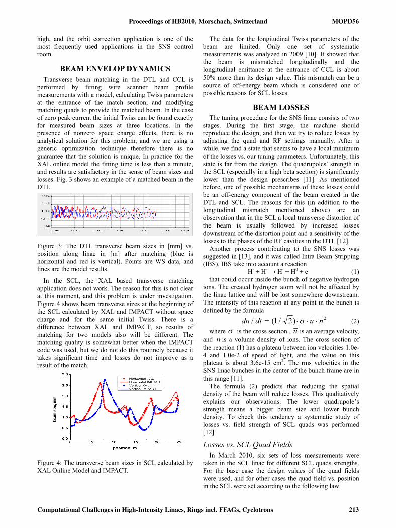
performed by fitting wire scanner beam profile measurements with a model, calculating Twiss parameters at the entrance of the match section, and modifying matching quads to provide the matched beam. In the case of zero peak current the initial Twiss can be found exactly for measured beam sizes at three locations. In the presence of nonzero space charge effects, there is no analytical solution for this problem, and we are using a generic optimization technique therefore there is no guarantee that the solution is unique. In practice for the XAL online model the fitting time is less than a minute, and results are satisfactory in the sense of beam sizes and losses. Fig. 3 shows an example of a matched beam in the DTL.
Figure 3: The DTL transverse beam sizes in [mm] vs. position along linac in [m] after matching (blue is horizontal and red is vertical). Points are WS data, and lines are the model results.
In the SCL, the XAL based transverse matching application does not work. The reason for this is not clear at this moment, and this problem is under investigation. Figure 4 shows beam transverse sizes at the beginning of the SCL calculated by XAL and IMPACT without space charge and for the same initial Twiss. There is a difference between XAL and IMPACT, so results of matching for two models also will be different. The matching quality is somewhat better when the IMPACT code was used, but we do not do this routinely because it takes significant time and losses do not improve as a result of the match.
Figure 4: The transverse beam sizes in SCL calculated by XAL Online Model and IMPACT.
The data for the longitudinal Twiss parameters of the beam are limited. Only one set of systematic measurements was analyzed in 2009 [10]. It showed that the beam is mismatched longitudinally and the longitudinal emittance at the entrance of CCL is about 50% more than its design value. This mismatch can be a source of off-energy beam which is considered one of possible reasons for SCL losses.
BEAM LOSSES The tuning procedure for the SNS linac consists of two
stages. During the first stage, the machine should reproduce the design, and then we try to reduce losses by adjusting the quad and RF settings manually. After a while, we find a state that seems to have a local minimum of the losses vs. our tuning parameters. Unfortunately, this state is far from the design. The quadrupoles’ strength in the SCL (especially in a high beta section) is significantly lower than the design prescribes [11]. As mentioned before, one of possible mechanisms of these losses could be an off-energy component of the beam created in the DTL and SCL. The reasons for this (in addition to the longitudinal mismatch mentioned above) are an observation that in the SCL a local transverse distortion of the beam is usually followed by increased losses downstream of the distortion point and a sensitivity of the losses to the phases of the RF cavities in the DTL [12].
Another process contributing to the SNS losses was suggested in [13], and it was called Intra Beam Stripping (IBS). IBS take into account a reaction
H- + H- → H- + H0 + e (1) that could occur inside the bunch of negative hydrogen
ions. The created hydrogen atom will not be affected by the linac lattice and will be lost somewhere downstream. The intensity of this reaction at any point in the bunch is defined by the formula
2)2/1(/ nudtdn ⋅⋅⋅= σ (2) where σ is the cross section , u is an average velocity,
and n is a volume density of ions. The cross section of the reaction (1) has a plateau between ion velocities 1.0e-4 and 1.0e-2 of speed of light, and the value on this plateau is about 3.6e-15 cm2. The rms velocities in the SNS linac bunches in the center of the bunch frame are in this range [11].
The formula (2) predicts that reducing the spatial density of the beam will reduce losses. This qualitatively explains our observations. The lower quadrupole’s strength means a bigger beam size and lower bunch density. To check this tendency a systematic study of losses vs. field strength of SCL quads was performed [12].
Losses vs. SCL Quad Fields In March 2010, six sets of loss measurements were
taken in the SCL linac for different SCL quads strengths. For the base case the design values of the quad fields were used, and for other cases the quad field vs. position in the SCL were set according to the following law
Proceedings of HB2010, Morschach, Switzerland MOPD56
Computational Challenges in High-Intensity Linacs, Rings incl. FFAGs, Cyclotrons 213

)/1( 21 LsCCBB design −⋅⋅= for Ls ≤ (3)
1CBB design ⋅= for Ls ≥ (4) where s is the position of the quadrupole in the SCL,
L is the length of the SCL part where all RF cavities are located, and designB is the design field. The values of 1C
and 2C parameters are defined in Table 1.
Table 1: Parameters in Formulas (3)-(4)
Case # C1 C2
0 1.000 0
1 0.975 0.05
2 0.950 0.10
3 0.925 0.15
4 0.900 0.20
5 0.875 0.25
The losses for cases 0-5 monotonically decreases everywhere in the SCL except for case 5 when the change in quadrupole field caused significant mismatching at the beginning. The bar-chart of the losses for the design and for case #5 are shown in Fig. 5.
Figure 5: The measured SCL losses normalized by the beam charge for the design and reduced quad strengths.
None of the aforementioned simulation codes have a model to describe the IBS process and to estimate related losses. Nevertheless, we can estimate the relative loss intensity per unit length assuming the 6D Gaussian distribution the particles in the bunch, and assuming that we know the RMS parameters for all phase-space coordinates (see [13], the formula is simplified by dropping out a correction factor that can give about 15% increase)
22
22222
81
γσσσπ
θθγθγσ
zyx
zyxNdsdN
N++⋅⋅
= (5)
Where γ is a relativistic factor, zyx ,,σ are rms bunch
sizes, N is a number of ions in the bunch, yx,θ are
transverse angular spreads, and zθ is a longitudinal momentum spread.
The loss distribution predicted by the formula (5) for all cases is shown in Fig. 6. The rms bunch sizes and momentum spreads were calculated by the XAL online model. The distribution of the simulated losses in Fig. 6 is different from the measured ones in Fig. 5, but we cannot compare them directly. Our model does not transport neutral hydrogen atoms created by IBS to a place where they will be lost, so the whole picture in Fig. 6 should be shifted to the right (downstream). A more realistic model of IBS and losses induced by this process should be implemented in a multi-particle simulation code.
Figure 6: Simulated losses in SCL for all six cases (see Table 1.).
Despite the difference in the loss distribution, we tried to calculate the sum of all BLM detectors in the SCL and the integrated losses in Fig. 6. The result is shown in Fig. 7. The agreement between IBS simulations and measured losses for cases 1-4 from Table 1 tells that the intra beam stripping could be an important contributor to beam losses.
Figure 7: The total losses in SCL caused by IBS in SCL for all six cases (see Table 1.).
MOPD56 Proceedings of HB2010, Morschach, Switzerland
214 Computational Challenges in High-Intensity Linacs, Rings incl. FFAGs, Cyclotrons

On the other hand, the case #5 shows that losses could be created by a conventional transverse beam mismatch, and future studies are needed for clear understanding of different contributions to the losses. Future experiments could use the fact that once neutral hydrogen atoms are created by IBS somewhere, the downstream losses due to these atoms landing will not be affected by the lattice between these two points.
CONCLUSIONS The longitudinal tuning and orbit correction practice
show that we have a good understanding of the single particle dynamics in the SNS linac. Existing disagreements between models and measured trajectories can be explained and will be fixed in the future.
The thus far unsuccessful transverse matching for the SCL part of the linac means that our models or matching procedures are inadequate. The discrepancies could be related to the SCL RF cavity models or the space change simulation uncertainties, because we did not perform reliable longitudinal emittance measurements.
At this moment we do not have a realistic model for beam losses. The one candidate for mechanism of the observed losses that is not implemented in any simulation codes used at SNS is the intra beam scattering. IBS should be included into the simulation code for the SNS project.
ACKNOWLEDGEMENTS The work was performed at SNS, ORNL. SNS is
managed by UT-Battelle, LLC, under contract DE-AC05-00OR22725 for the U.S. Department of Energy.
REFERENCES [1] S. Nath et al., “Longitudinal Beam Dynamics of the
SNS SRF Linac,” Proc. of EPAC2002, Paris, 2002, pp. 1031-1033.
[2] J. Stovall, et al., “Expected Beam Performance of the SNS Linac,” Proc. of the 2001 Particle. Accelerator Conference, Chicago, Ill., June 18-22, 2001, p. 446.
[3] C.K. Allen et al., “A Novel Online Simulator for Applications Requiring a Model Reference”, ICALEPCS 2003 Conference Proceedings, Kyongju, Korea, October 13-17, 2003, pp. 315-317.
[4] J. Galambos, et al, “XAL Application Programming Structure,” p. 79, Proceedings of 2005 Particle Accelerator Conference.
[5] K. R. Crandall, D. P. Rusthoi, TRACE 3-D Documentation. LANL Report No LA-UR-97-886, 1997.
[6] H. Takeda, Parmila. LANL Report No. LA-UR-98-4478, 2005.
[7] J. Qiang, R.D. Ryne, S. Habib, and V. Decyk, J. Comp. Phys. 163, 434-451 (2000).
[8] V.N. Aseev et al., Proceedings of PAC05 Conference, Knoxville, Tennessee, May 16-20,2005
[9] A. Shishlo, A. Aleksandrov, Using the Online Single Particle Model for SNS Accelerator Tuning. Proceedings of Hadron Beam 2008, Nashville, TN, pp. 203-206
[10] Sarah Cousineau, private conversation [11] A. Shishlo, “Beam Measurement and Simulation at
the SNS”, this Proceedings. [12] John Galambos, private conversation. [13] V. Lebedev, et al., “Intrabeam Stripping in H-
Linac”, To be published. 25th International Linear Accelerator Conference, LINAC10, Tsukuba, Japan, 12-17 September 2010.
Proceedings of HB2010, Morschach, Switzerland MOPD56
Computational Challenges in High-Intensity Linacs, Rings incl. FFAGs, Cyclotrons 215


![Simulations for the SNS Linac - CERN › HB2010 › papers › mopd56.pdf · accelerator code which include s realistic 3D space charge calculations [7]. At SNS it is used for offline](https://img.dokumen.tips/doc/110x75/5f0f5d557e708231d443cb8d/simulations-for-the-sns-linac-cern-a-hb2010-a-papers-a-mopd56pdf-accelerator.jpg)