Embed Size (px)
Citation preview
2
Simulation of the Scavenging Process in Two-Stroke Engines
María Isabel Lamas Galdo and Carlos G. Rodríguez Vidal Universidade da Coruña
Spain
1. Introduction
It is widely known that the scavenging process plays a very important role in the performance and efficiency of two-stroke engines. Briefly, scavenging is the process by which the fresh charge displaces the burnt gas from the cylinder. Due to the difficulties associated with the measurement techniques, CFD (Computational Fluid Dynamics) is a very helpful tool to analyze the flow pattern inside the cylinder. CFD simulations can provide more detailed information than experimental studies. For this reason, this chapter focuses on a numerical analysis to simulate the fluid flow and heat transfer inside the cylinder at the scavenging process.
This chapter is a continuation and extension of previous works (Lamas-Galdo et al., 2011; Lamas & Rodriguez, 2012), in which CFD models were developed and validated with experimental results. The content is organized as follows. A brief description of two-stroke engines is given in Section 2. The mathematical model, i.e., the governing equations are presented in Section 3 and the numerical model is discussed in Section 4. After that, the results are shown in Section 5 and the conclusions of this chapter are discussed in Section 6.
2. Introduction to the two-stroke engine
Although the focus of this chapter is the numerical treatment of the scavenging process, it is important to introduce certain introductory aspects about the performance of two-stroke engines. This will facilitate the reader’s understanding of the chapter.
2.1 Mechanical aspects
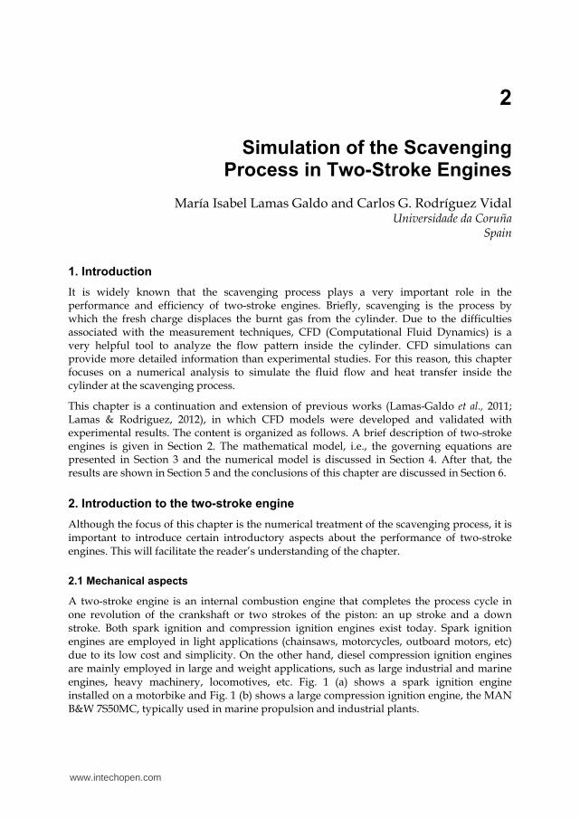
A two-stroke engine is an internal combustion engine that completes the process cycle in one revolution of the crankshaft or two strokes of the piston: an up stroke and a down stroke. Both spark ignition and compression ignition engines exist today. Spark ignition engines are employed in light applications (chainsaws, motorcycles, outboard motors, etc) due to its low cost and simplicity. On the other hand, diesel compression ignition engines are mainly employed in large and weight applications, such as large industrial and marine engines, heavy machinery, locomotives, etc. Fig. 1 (a) shows a spark ignition engine installed on a motorbike and Fig. 1 (b) shows a large compression ignition engine, the MAN B&W 7S50MC, typically used in marine propulsion and industrial plants.
www.intechopen.com
Numerical Modelling
28
(a) (b)
Fig. 1. (a) Spark ignition gasoline engine installed on a motorcycle. (b) Compression ignition diesel engine MAN B&W 7S50MC installed on a ship.
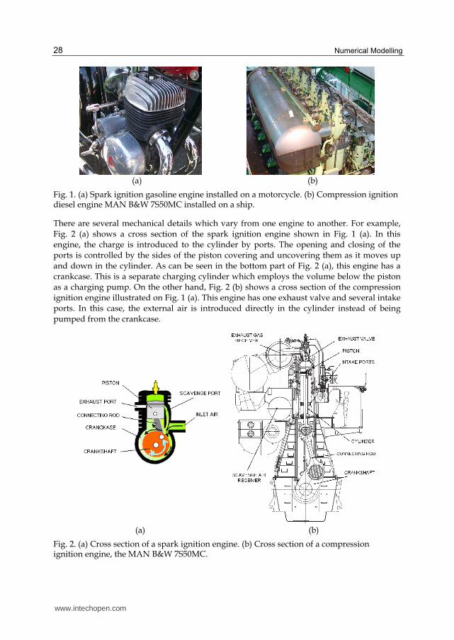
There are several mechanical details which vary from one engine to another. For example, Fig. 2 (a) shows a cross section of the spark ignition engine shown in Fig. 1 (a). In this engine, the charge is introduced to the cylinder by ports. The opening and closing of the ports is controlled by the sides of the piston covering and uncovering them as it moves up and down in the cylinder. As can be seen in the bottom part of Fig. 2 (a), this engine has a crankcase. This is a separate charging cylinder which employs the volume below the piston as a charging pump. On the other hand, Fig. 2 (b) shows a cross section of the compression ignition engine illustrated on Fig. 1 (a). This engine has one exhaust valve and several intake ports. In this case, the external air is introduced directly in the cylinder instead of being pumped from the crankcase.
(a) (b)
Fig. 2. (a) Cross section of a spark ignition engine. (b) Cross section of a compression ignition engine, the MAN B&W 7S50MC.
www.intechopen.com
Simulation of the Scavenging Process in Two-Stroke Engines
29
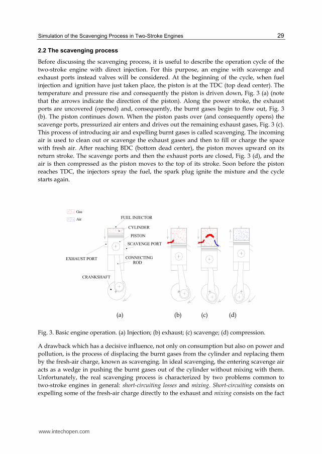
2.2 The scavenging process
Before discussing the scavenging process, it is useful to describe the operation cycle of the
two-stroke engine with direct injection. For this purpose, an engine with scavenge and
exhaust ports instead valves will be considered. At the beginning of the cycle, when fuel
injection and ignition have just taken place, the piston is at the TDC (top dead center). The
temperature and pressure rise and consequently the piston is driven down, Fig. 3 (a) (note
that the arrows indicate the direction of the piston). Along the power stroke, the exhaust
ports are uncovered (opened) and, consequently, the burnt gases begin to flow out, Fig. 3
(b). The piston continues down. When the piston pasts over (and consequently opens) the
scavenge ports, pressurized air enters and drives out the remaining exhaust gases, Fig. 3 (c).
This process of introducing air and expelling burnt gases is called scavenging. The incoming
air is used to clean out or scavenge the exhaust gases and then to fill or charge the space
with fresh air. After reaching BDC (bottom dead center), the piston moves upward on its
return stroke. The scavenge ports and then the exhaust ports are closed, Fig. 3 (d), and the
air is then compressed as the piston moves to the top of its stroke. Soon before the piston
reaches TDC, the injectors spray the fuel, the spark plug ignite the mixture and the cycle
starts again.
SCAVENGE PORT
EXHAUST PORT
CRANKSHAFT
CONNECTING
ROD
FUEL INJECTOR
CYLINDER
PISTON
Gas
Air
(a) (b) (c) (d)
Fig. 3. Basic engine operation. (a) Injection; (b) exhaust; (c) scavenge; (d) compression.
A drawback which has a decisive influence, not only on consumption but also on power and
pollution, is the process of displacing the burnt gases from the cylinder and replacing them
by the fresh-air charge, known as scavenging. In ideal scavenging, the entering scavenge air
acts as a wedge in pushing the burnt gases out of the cylinder without mixing with them.
Unfortunately, the real scavenging process is characterized by two problems common to
two-stroke engines in general: short-circuiting losses and mixing. Short-circuiting consists on
expelling some of the fresh-air charge directly to the exhaust and mixing consists on the fact
www.intechopen.com
Numerical Modelling
30
that there is a small amount of residual gases which remain trapped without being expelled,
being mixed with some of the new air charge.
The main difficulty involved in designing an effective scavenging system is that there are too
involving variables: piston chamber geometry, intake and exhaust ports design, opening and
closing timings, compression ratio, fuel composition, inlet and exhaust pressures, etc, being
necessary a detailed study to embrace all this factors. For years, the study of the fluid flow
inside engines has been mainly supported by experimental tests such as PIV (Particle Image
Velocity), LDA (Laser Doppler Anemometry), ICCD cameras, etc. However, these
experimental tests are very laborious and expensive. As an alternative solution to experimental
techniques, CFD has recently become a useful tool to study the fluid flow inside engines. In the
field of engines, CFD is especially useful to design complex components such as combustion
chambers, manifolds, injectors and other parameters. The first numerical simulations of
engines appeared in the eighties (Sher, 1980; Carpenter & Ramos, 1986; Sweeny et al., 1985;
Ahmadi-Befrui et al., 1989) but, unfortunately, these first numerical studies only provided,
with poor accuracy, information about the general configuration of the flow field inside the
cylinder. Besides, at that time it was very difficult to carry out a three-dimensional analysis.
After these first numerical studies, a lot of works appeared in the nineties and in recent years.
The number of CFD codes has also increased noticeably, appearing studies using KIVA
(Epstein et al., 1991; Amsden et al., 1992), STAR-CD (Raghunathan & Kenny, 1997; Yu et al.
1997; Zahn et al., 2000; Hariharan et al., 2009), FIRE (Hori et al., 1995; Laimböck et al., 1998)
Fluent (Pitta & Kuderu, 2008; Lamas-Galdo et al., 2011), CFX (Albanesi et al., 2009), etc.
3. Mathematical model
Once the basic performance of two-stroke engines was described, the methodology to simulate the scavenging process will be treated in this section.
3.1 Governing equations
The governing equations of the flow inside the cylinder are the Navier-Stokes ones. The
energy equation is also needed to compute the thermal problem. Finally, as there are two
components (air and burnt gases), one more equation must be added to characterize the
propagating interface. These equations are briefly described in what follows.
In Cartesian tensor form, the continuity equation is given by:
0ii
ut x
(1)
where ρ is the density and u the velocity. It is very common to consider the flows as ideal gasses, so the density can be calculated as follows:
p
RT (2)
where p is the pressure, T the temperature and R the ideal gas constant. The momentum
conservation equation is given by:
www.intechopen.com
Simulation of the Scavenging Process in Two-Stroke Engines
31
( ) ( )ij
i i jj i j
pu u u
t x x x
(3)
where τij is the stress tensor. If the fluid is treated as Newtonian, the stress tensor components are given by:
2
3
ji kij ij
j i k
uu u
x x x (4)
As only the scavenging process and not the combustion is treated on this chapter, only two components need to be computed: burnt gas and unburnt gas (air). In order to characterize the propagating interface, the following equation is solved:
( ) 0( )
Y Vair
air
Y
t
(5)
where Yair is the mass fraction of the air. The mass fraction of the burnt gases, Ygas , is given by the restriction that the total mass fraction must sum to unity:
1Y Ygas air (6)
3.2 Turbulence
Today's standard in engine simulation are Reynolds Averaged Navier-Stokes (RANS)
methods. Another approach are Large Eddy Simulation (LES) techniques. LES and RANS
techniques differ in the way they address the present impossibility to resolve all the scales
present in engine flows. RANS simulations are based on a statistical averaging to solve only
the mean flow. This implies that modelling concerns the whole spectrum of scales. In LES, a
spatial or temporal filtering is used to represent the large turbulent scales of the flow, which
are directly resolved, while the small scales are modeled. In LES, modeling thus concerns a
much smaller part of the spectrum, which leads to an improvement of predictivity as
compared to RANS. LES inherently allows to address large scale unsteady phenomena, and
thus has a good potential to predict engine unsteadiness. The problem is that LES would
lead to a CPU time that is way beyond reach of present supercomputers. Therefore, the use
o LES is not very common.
In the field of RANS methods, the two-equation model standard k-ε is the most used to
simulate engines. The RNG k-ε model is also widely employed, specially in the cases of
swirling flows.
The momentum conservation equation for a turbulent flow is given by:
' '( ) ( ) ( )ij
i i j i jj i j j
pu u u u u
t x x x x
(7)
A common method to model the Reynolds stresses, ' 'i ju u , is the Boussinesq hypothesis to
relate the Reynolds stresses to the mean velocity gradients:
www.intechopen.com
Numerical Modelling
32
' ' 2
3
ji ki j t t ij
j i k
uu uu u k
x x x (8)
where ├ij is the Kronecker delta (├ij=1 if i=j and ├ij=0 if i≠j), which is included to make the
formula applicable to the normal Reynolds stresses for which i=j (Versteeg and
Malalasekera, 2007) and μt is the turbulent viscosity. The k-ε model includes two differential
equations, corresponding to the turbulent kinetic energy (k), and its dissipation rate (┝), given by Ecs. (9) and (10) respectively.
( ) ( )i k t k b Mi j j
kk ku G G Y
t x x x (9)
2
1 3 2( ) ( ) ti k bi j j
u C G G G Ct x x x k k (10)
In the above equations, Gk represents the generation of turbulence kinetic energy due to the
mean velocity gradients; Gb is the generation of turbulence kinetic energy due to buoyancy;
YM represents the contribution of the fluctuating dilatation in compressible turbulence to the
overall dissipation rate. Cμ, C1┝, C2┝, C3┝, σk and σ┝ are constants and the terms αk and α┝ represent the inverse effective Prandtl numbers for k and ┝ respectively. These quantities
were obtained by a RNG modified method which accounts for the effects of swirl or
rotation. Details of the procedure are given elsewhere, (Fluent Inc., 2006).
The turbulent viscosity, μt, is computed by combining k and ┝ as follows:
2
t
kC (11)
Concerning the heat transfer problem, turbulent heat transport can be modeled using the
concept of Reynolds’ analogy to turbulent momentum transfer. The energy equation is thus
given by the following:
( ) ( )Pr
p ti t i ij
i j j
C TE u E p k u
t x x x
(12)
where E is the total energy.
4. Numerical procedure
In this section, the generation of the mesh and other numerical details will be described.
Particularly, this section focuses on the engine studied in Lamas-Galdo et al. (2011), which is
shown in Fig. 1 (a) and Fig. 2 (a). This is a single cylinder two-stroke engine. The geometry
and distribution diagram are shown in Fig. 4, and other technical specifications are
summarized in Table 1.
www.intechopen.com
Simulation of the Scavenging Process in Two-Stroke Engines
33
BDC
TDC
MAIN
SCAVENGE PORT
MAIN
SCAVENGE PORT
AUXILIARY
SCAVENGE PORT EXHAUST PORT
EXHAUST PORT
AUXILIARY
SCAVENGE PORT
MAIN
SCAVENGE PORT
(a) (b)
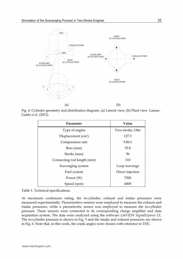
Fig. 4. Cylinder geometry and distribution diagram. (a) Lateral view; (b) Plant view. Lamas-Galdo et al. (2011).
Parameter Value
Type of engine Two-stroke, Otto
Displacement (cm3) 127.3
Compression rate 9.86:1
Bore (mm) 53.8
Stroke (mm) 56
Connecting rod length (mm) 110
Scavenging system Loop scavenge
Fuel system Direct injection
Power (W) 7500
Speed (rpm) 6000
Table 1. Technical specifications.
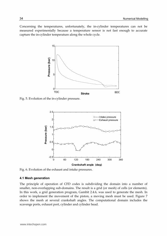
At maximum continuum rating, the in-cylinder, exhaust and intake pressures were measured experimentally. Piezoresistive sensors were employed to measure the exhaust and intake pressures, while a piezoelectric sensor was employed to measure the in-cylinder pressure. These sensors were connected to its corresponding charge amplifier and data acquisition system. The data were analyzed using the software LabVIEW SignalExpress LE. The in-cylinder pressure is shown in Fig. 5 and the intake and exhaust pressures are shown in Fig. 6. Note that, in this work, the crank angles were chosen with reference to TDC.
www.intechopen.com
Numerical Modelling
34
Concerning the temperatures, unfortunately, the in-cylinder temperatures can not be
measured experimentally because a temperature sensor is not fast enough to accurate
capture the in-cylinder temperature along the whole cycle.
0
5
10
15
Pre
ssu
re (
bar)
StrokeTDC BDC
Fig. 5. Evolution of the in-cylinder pressure.
0 60 120 180 240 300 360-0.5
0
0.5
1
1.5
2
2.5
Crankshaft angle (deg)
Pre
ss
ure
(b
ar)
Intake pressureIntake pressure
Exhaust pressureExhaust pressure
Fig. 6. Evolution of the exhaust and intake pressures.
4.1 Mesh generation
The principle of operation of CFD codes is subdividing the domain into a number of
smaller, non-overlapping sub-domains. The result is a grid (or mesh) of cells (or elements).
In this work, a grid generation program, Gambit 2.4.6, was used to generate the mesh. In
order to implement the movement of the piston, a moving mesh must be used. Figure 7
shows the mesh at several crankshaft angles. The computational domain includes the
scavenge ports, exhaust port, cylinder and cylinder head.
www.intechopen.com
Simulation of the Scavenging Process in Two-Stroke Engines
35
(a) (b)
(c) (d)
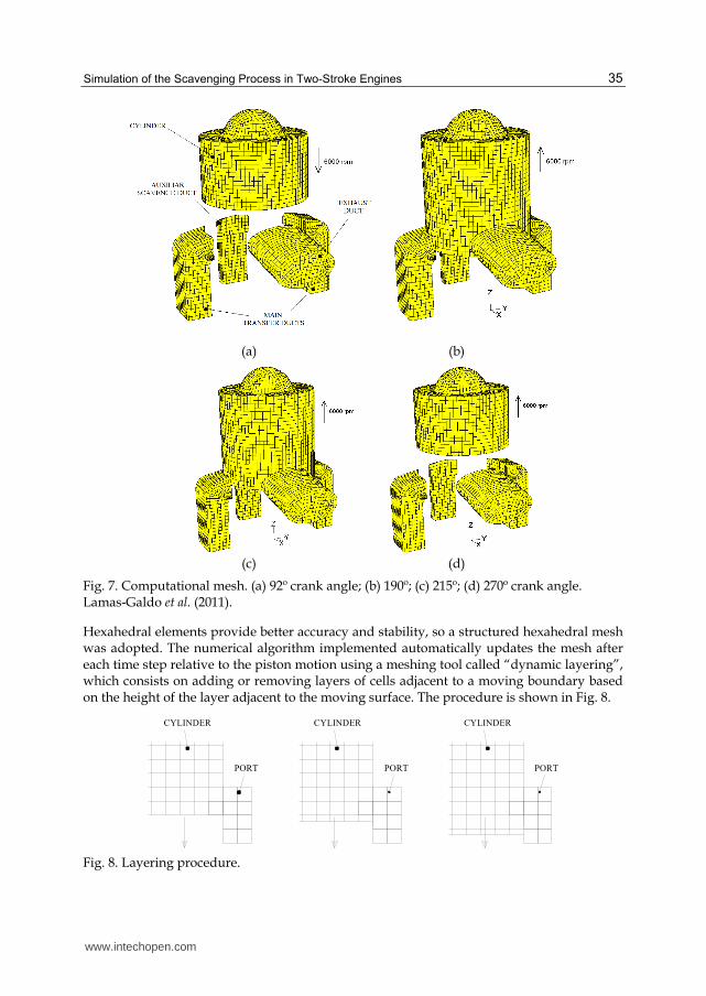
Fig. 7. Computational mesh. (a) 92º crank angle; (b) 190º; (c) 215º; (d) 270º crank angle. Lamas-Galdo et al. (2011).
Hexahedral elements provide better accuracy and stability, so a structured hexahedral mesh was adopted. The numerical algorithm implemented automatically updates the mesh after each time step relative to the piston motion using a meshing tool called “dynamic layering”, which consists on adding or removing layers of cells adjacent to a moving boundary based on the height of the layer adjacent to the moving surface. The procedure is shown in Fig. 8.
CYLINDER
PORT PORT
CYLINDER CYLINDER
PORT
Fig. 8. Layering procedure.
www.intechopen.com
Numerical Modelling
36
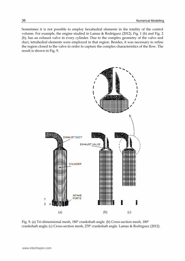
Sometimes it is not possible to employ hexahedral elements in the totality of the control volume. For example, the engine studied in Lamas & Rodríguez (2012), Fig. 1 (b) and Fig. 2 (b), has an exhaust valve in every cylinder. Due to the complex geometry of the valve and duct, tetrahedral elements were employed in that region. Besides, it was necessary to refine the region closed to the valve in order to capture the complex characteristics of the flow. The result is shown in Fig. 9.
(a) (b) (c)
Fig. 9. (a) Tri-dimensional mesh, 180º crankshaft angle. (b) Cross-section mesh, 180º crankshaft angle; (c) Cross-section mesh, 270º crankshaft angle. Lamas & Rodríguez (2012).
www.intechopen.com
Simulation of the Scavenging Process in Two-Stroke Engines
37
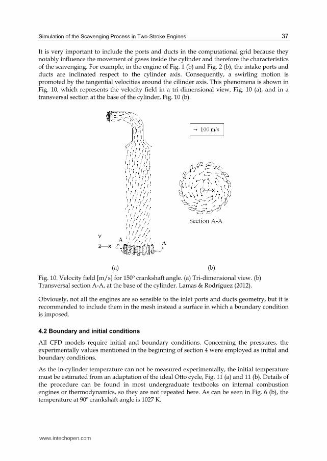
It is very important to include the ports and ducts in the computational grid because they notably influence the movement of gases inside the cylinder and therefore the characteristics of the scavenging. For example, in the engine of Fig. 1 (b) and Fig. 2 (b), the intake ports and ducts are inclinated respect to the cylinder axis. Consequently, a swirling motion is promoted by the tangential velocities around the cilinder axis. This phenomena is shown in Fig. 10, which represents the velocity field in a tri-dimensional view, Fig. 10 (a), and in a transversal section at the base of the cylinder, Fig. 10 (b).
(a) (b)
Fig. 10. Velocity field [m/s] for 150º crankshaft angle. (a) Tri-dimensional view. (b) Transversal section A-A, at the base of the cylinder. Lamas & Rodríguez (2012).
Obviously, not all the engines are so sensible to the inlet ports and ducts geometry, but it is recommended to include them in the mesh instead a surface in which a boundary condition is imposed.
4.2 Boundary and initial conditions
All CFD models require initial and boundary conditions. Concerning the pressures, the experimentally values mentioned in the beginning of section 4 were employed as initial and boundary conditions.
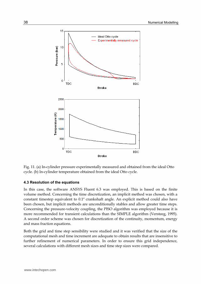
As the in-cylinder temperature can not be measured experimentally, the initial temperature must be estimated from an adaptation of the ideal Otto cycle, Fig. 11 (a) and 11 (b). Details of the procedure can be found in most undergraduate textbooks on internal combustion engines or thermodynamics, so they are not repeated here. As can be seen in Fig. 6 (b), the temperature at 90º crankshaft angle is 1027 K.
www.intechopen.com
Numerical Modelling
38
Fig. 11. (a) In-cylinder pressure experimentally measured and obtained from the ideal Otto
cycle. (b) In-cylinder temperature obtained from the ideal Otto cycle.
4.3 Resolution of the equations
In this case, the software ANSYS Fluent 6.3 was employed. This is based on the finite
volume method. Concerning the time discretization, an implicit method was chosen, with a
constant timestep equivalent to 0.1º crankshaft angle. An explicit method could also have
been chosen, but implicit methods are unconditionally stables and allow greater time steps.
Concerning the pressure-velocity coupling, the PISO algorithm was employed because it is
more recommended for transient calculations than the SIMPLE algorithm (Versteeg, 1995).
A second order scheme was chosen for discretization of the continuity, momentum, energy
and mass fraction equations.
Both the grid and time step sensibility were studied and it was verified that the size of the
computational mesh and time increment are adequate to obtain results that are insensitive to
further refinement of numerical parameters. In order to ensure this grid independence,
several calculations with different mesh sizes and time step sizes were compared.
www.intechopen.com
Simulation of the Scavenging Process in Two-Stroke Engines
39
5. Results
5.1 Pressure field and validation of the code
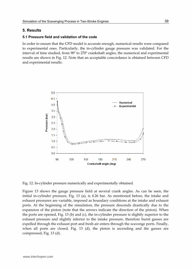
In order to ensure that the CFD model is accurate enough, numerical results were compared
to experimental ones. Particularly, the in-cylinder gauge pressure was validated. For the
interval of time studied, from 90º to 270º crankshaft angles, the numerical and experimental
results are shown in Fig. 12. Note that an acceptable concordance is obtained between CFD
and experimental results.
Fig. 12. In-cylinder pressure numerically and experimentally obtained.
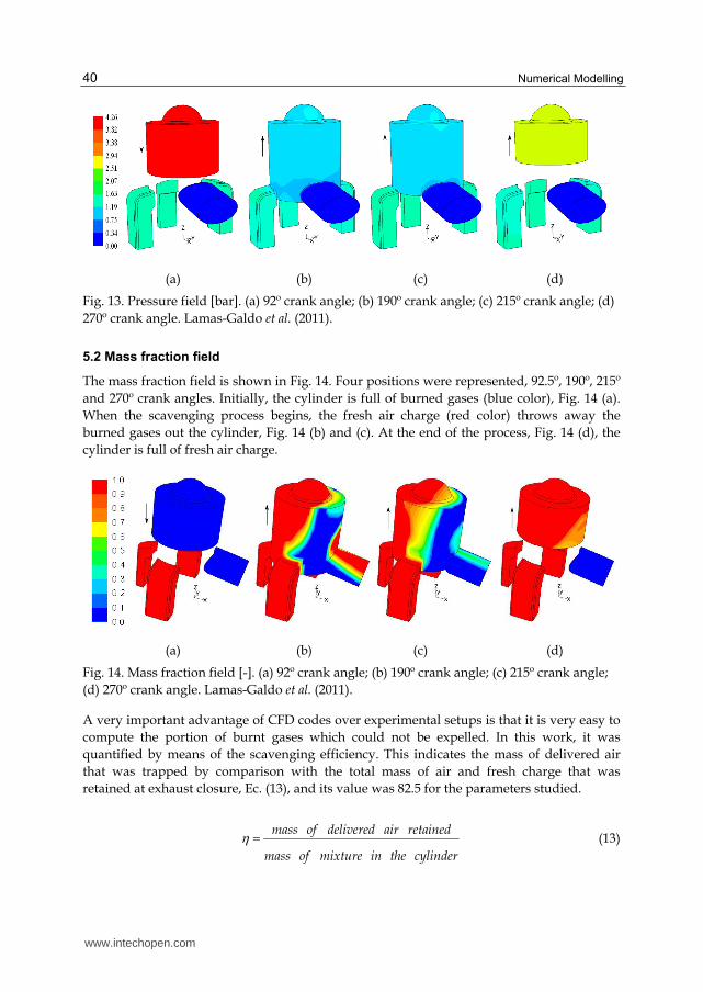
Figure 13 shows the gauge pressure field at several crank angles. As can be seen, the
initial in-cylinder pressure, Fig. 13 (a), is 4.26 bar. As mentioned before, the intake and
exhaust pressures are variable, imposed as boundary conditions at the intake and exhaust
ports. At the beginning of the simulation, the pressure descends drastically due to the
expansion of the piston (note that the arrows indicate the direction of the piston). When
the ports are opened, Fig. 13 (b) and (c), the in-cylinder pressure is slightly superior to the
exhaust pressure and slightly inferior to the intake pressure, therefore burnt gasses are
expelled through the exhaust port and fresh air enters through the scavenge ports. Finally,
when all ports are closed, Fig. 13 (d), the piston is ascending and the gasses are
compressed, Fig. 13 (d).
www.intechopen.com
Numerical Modelling
40
(a) (b) (c) (d)
Fig. 13. Pressure field [bar]. (a) 92º crank angle; (b) 190º crank angle; (c) 215º crank angle; (d)
270º crank angle. Lamas-Galdo et al. (2011).
5.2 Mass fraction field
The mass fraction field is shown in Fig. 14. Four positions were represented, 92.5º, 190º, 215º
and 270º crank angles. Initially, the cylinder is full of burned gases (blue color), Fig. 14 (a).
When the scavenging process begins, the fresh air charge (red color) throws away the
burned gases out the cylinder, Fig. 14 (b) and (c). At the end of the process, Fig. 14 (d), the
cylinder is full of fresh air charge.
(a) (b) (c) (d)
Fig. 14. Mass fraction field [-]. (a) 92º crank angle; (b) 190º crank angle; (c) 215º crank angle;
(d) 270º crank angle. Lamas-Galdo et al. (2011).
A very important advantage of CFD codes over experimental setups is that it is very easy to
compute the portion of burnt gases which could not be expelled. In this work, it was
quantified by means of the scavenging efficiency. This indicates the mass of delivered air
that was trapped by comparison with the total mass of air and fresh charge that was
retained at exhaust closure, Ec. (13), and its value was 82.5 for the parameters studied.
mass of delivered air retained
mass of mixture in the cylinder
(13)
www.intechopen.com
Simulation of the Scavenging Process in Two-Stroke Engines
41
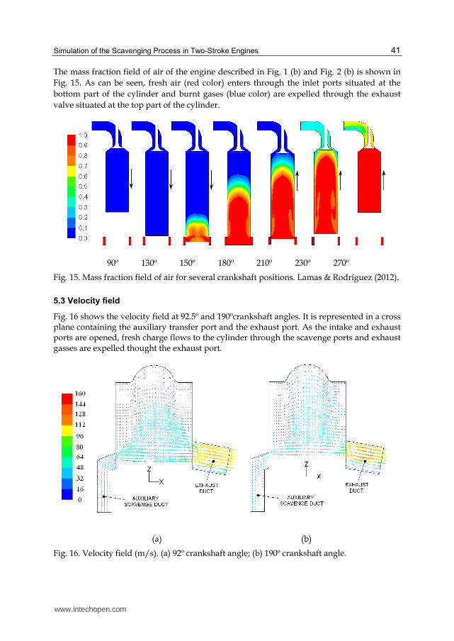
The mass fraction field of air of the engine described in Fig. 1 (b) and Fig. 2 (b) is shown in
Fig. 15. As can be seen, fresh air (red color) enters through the inlet ports situated at the
bottom part of the cylinder and burnt gases (blue color) are expelled through the exhaust
valve situated at the top part of the cylinder.
90º 130º 150º 180º 210º 230º 270º
Fig. 15. Mass fraction field of air for several crankshaft positions. Lamas & Rodríguez (2012).
5.3 Velocity field
Fig. 16 shows the velocity field at 92.5º and 190ºcrankshaft angles. It is represented in a cross plane containing the auxiliary transfer port and the exhaust port. As the intake and exhaust ports are opened, fresh charge flows to the cylinder through the scavenge ports and exhaust gasses are expelled thought the exhaust port.
(a) (b)
Fig. 16. Velocity field (m/s). (a) 92º crankshaft angle; (b) 190º crankshaft angle.
www.intechopen.com
Numerical Modelling
42
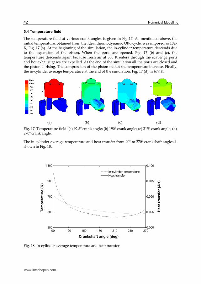
5.4 Temperature field
The temperature field at various crank angles is given in Fig 17. As mentioned above, the initial temperature, obtained from the ideal thermodynamic Otto cycle, was imposed as 1027 K, Fig. 17 (a). At the beginning of the simulation, the in-cylinder temperature descends due to the expansion of the piston. When the ports are opened, Fig. 17 (b) and (c), the temperature descends again because fresh air at 300 K enters through the scavenge ports and hot exhaust gases are expelled. At the end of the simulation all the ports are closed and the piston is rising. The compression of the piston makes the temperature increase. Finally, the in-cylinder average temperature at the end of the simulation, Fig. 17 (d), is 677 K.
(a) (b) (c) (d)
Fig. 17. Temperature field. (a) 92.5º crank angle; (b) 190º crank angle; (c) 215º crank angle; (d) 270º crank angle.
The in-cylinder average temperature and heat transfer from 90º to 270º crankshaft angles is shown in Fig. 18.
90 120 150 180 210 240 270300
500
700
900
1100
0.000
0.025
0.050
0.075
0.100
Crankshaft angle (deg)
Tem
pera
ture
(K
)
Heat
tran
sfe
r (J
/s)
In-cylinder temperatureIn-cylinder temperature
Heat transferHeat transfer
Fig. 18. In-cylinder average temperatura and heat transfer.
www.intechopen.com
Simulation of the Scavenging Process in Two-Stroke Engines
43
6. Conclusions
In the present chapter, a CFD analysis was carried out to study the scavenging process of two-stroke engines. The results were satisfactory compared to experimental data. In general, this study shows that CFD predictions yield reasonably accurate results that allow improving the knowledge of the fluid flow characteristics.
This model is very useful to design the scavenging system of new two-stroke engines. The pressure field is useful for identifying areas where the gas flow is inefficient and should be corrected. The velocity field is useful for locating areas with too high, too low or inadequate orientation velocities. Finally, the mass fraction field is useful for checking the filling of fresh gases into the cylinder and detecting problems of short circuiting and gas drag.
Finally, it is very important to mention the disadvantages of CFD. First of all, a 3D CFD model is very tedious due to the large computational resources. Besides, the moving mesh required to simulate the movement of the piston is too computationally expensive to solve. Other disadvantage is that it must not be applied blindly as it has the capability to produce non-physical results due to erroneous modeling. The process of verification and validation of a CFD model is necessary to ensure the numerical model accurately captures the physical phenomena present. By comparing numerically obtained results with experimental results, confidence in the numerical model is achieved. Once thoroughly validated, a numerical model may be used to accurately predict the effect of design changes and experimentally unobservable phenomena.
7. References
Ahmadi-Befrui, B.; Brandstatter, W.; Kratochwill, H. (1989). Multidimensional calculation of the flow processes in a loop-scavenged two-stroke cycle engine. SAE Paper 890841.
Albanesi A., Destefanis C, Zanotti A. (2009) Intake port shape optimization in a four-valve high performance engine. Mecánica Computacional. Vol. 28, pp. 1355-1370.
Amsden, A. A.; O´Rourke, P. J.; Butler, T. D.; Meintjes, K. and Fansler, T. D. Comparisons of computed and measured three-dimensional velocity fields in a motored two-stroke engine. SAE Paper 920418, 1992.
Blair G.P. (1996). Design and Simulation of Two-Stroke Engines. SAE International. ISBN 978-1-56091-685-7, USA.
Carpenter, M. H.; Ramos, J. I. (1986). Modelling a gasoline-injected two-stroke cycle engine. SAE Paper 860167.
Creaven J.P., Kenny K.G., Cunningham G. (2001). A computational and experimental study of the scavenging flow in the transfer duct of a motored two-stroke cycle engine. Proc Instn Mech Engrs. Vol.215-D.
Epstein, P. H.; Reitz, R. D. and Foster, D. E. (1991). Computations of two-stroke cylinder and port scavenging. SAE Paper 919672.
Fluent 6.3 Documentation, 2006. Fluent Inc. Hariharan Ramamoorthy, Mahalakshmi N. V., Krishnamoorthy Jeyachandran. (2009).
Setting up a comprehensive CFD model of a small two stroke engine for simulation. International Journal of Applied Engineering Research. Vol. 4-11.
Hori, H.; Ogawa, T. and Toshihiko, K. (1985). CFD in-cylinder flow simulation of an engine and flow visualization. SAE Paper 950288.
www.intechopen.com
Numerical Modelling
44
Kato S., Nakagawa H., Kawahara Y., Adachi T., Nakashima M. (1991) Numerical analysis of the scavenging flow in a two stroke- cycle gasoline engine. JSME International Journal. Vol. 34-3, pp. 385-390.
Laimböck, F. J.; Meist, G. and Grilc, S. (1998). CFD application in compact engine development. SAE Paper 982016.
Lamas-Galdo, M.; Rodríguez-Vidal, C.; Rodríguez-García, J.; Fernández-Quintás, M. (2011). Modelo de Mecánica de Fluidos Computacional para el proceso de barrido en un motor Otto de dos tiempos. DYNA Ingeniería e Industria, vol. 86-2, pp. 165-172.
Lamas, M. I.; Rodríguez, C. G. (2012) CFD analysis of the scavenging process in the MAN B&W 7S50MC two-stroke diesel marine engine. Submitted to Journal of Ship Research.
Payri F., Benajes J., Margot X. et al. (2004). CFD modeling of the in-cylinder flow in direct-injection diesel engines. Computers & Fluids. Vol.33 p.995-1021.
Pitta S. R., Kuderu R. (2008). A computational fluid dynamics analysis on stratified scavenging system of medium capacity two-stroke internal combustion engines. Thermal Science. Vol. 12-1, pp. 33-42.
Raghunathan, B. D. and Kenny, R. G. (1997). CFD simulation and validation of the flow within a motored two-stroke engine. SAE Paper 970359.
Rahman M.M., Hamada K.I., Noor M.M. et al. (2010) Heat transfer characteristics of intake port for spark ignition engine: A comparative study. Journal of applied sciences. Vol.10-18, pp. 2019-2026.
Sher, E. (1989). An improved gas dynamic model simulating the scavenging process in a two-stroke cycle engine. SAE Paper 800037.
Sweeny, M. E. G.; Kenny, R. G.; Swann, G. B. G. and Blair, G. P. (1985). Computational fluid dynamics applied to two-stroke engine scavenging. SAE Paper 851519.
Yu, L.; Campbell, T. and Pollock, W. (1997). A simulation model for direct-fuel-injection of two-stroke gasoline engines. SAE Paper 970367.
Zahn, W.; Rosskamp, H.; Raffenberg, M. and Klimmek, A. (2000). Analysis of a stratified charging concept for high-performance two-stroke engine. SAE Paper 2000-01-0900.
Zancanaro F.V., Vielmo H.A. (2010) Numerical analysis of the fluid flow in a high swirled diesel engine. Proceedings of the 7th International Conference on Heat Transfer, Fluid Mechanics and Thermodynamics. Antalya-Turkey, 19-21 July 2010, pp. 387-392.
www.intechopen.com
Numerical ModellingEdited by Dr. Peep Miidla
ISBN 978-953-51-0219-9Hard cover, 398 pagesPublisher InTechPublished online 23, March, 2012Published in print edition March, 2012
InTech EuropeUniversity Campus STeP Ri Slavka Krautzeka 83/A 51000 Rijeka, Croatia Phone: +385 (51) 770 447 Fax: +385 (51) 686 166www.intechopen.com
InTech ChinaUnit 405, Office Block, Hotel Equatorial Shanghai No.65, Yan An Road (West), Shanghai, 200040, China
Phone: +86-21-62489820 Fax: +86-21-62489821
This book demonstrates applications and case studies performed by experts for professionals and students inthe field of technology, engineering, materials, decision making management and other industries in whichmathematical modelling plays a role. Each chapter discusses an example and these are ranging from well-known standards to novelty applications. Models are developed and analysed in details, authors carefullyconsider the procedure for constructing a mathematical replacement of phenomenon under consideration. Formost of the cases this leads to the partial differential equations, for the solution of which numerical methodsare necessary to use. The term Model is mainly understood as an ensemble of equations which describe thevariables and interrelations of a physical system or process. Developments in computer technology andrelated software have provided numerous tools of increasing power for specialists in mathematical modelling.One finds a variety of these used to obtain the numerical results of the book.
How to referenceIn order to correctly reference this scholarly work, feel free to copy and paste the following:
María Isabel Lamas Galdo and Carlos G. Rodríguez Vidal (2012). Simulation of the Scavenging Process inTwo-Stroke Engines, Numerical Modelling, Dr. Peep Miidla (Ed.), ISBN: 978-953-51-0219-9, InTech, Availablefrom: http://www.intechopen.com/books/numerical-modelling/simulation-of-the-scavenging-process-in-two-stroke-engines

© 2012 The Author(s). Licensee IntechOpen. This is an open access articledistributed under the terms of the Creative Commons Attribution 3.0License, which permits unrestricted use, distribution, and reproduction inany medium, provided the original work is properly cited.