Embed Size (px)
Citation preview
143
International Scientific Colloquium Modelling for Material Processing
Riga, June 8-9, 2006
Simulation of Plasma and Shielding Gas Flows in Welding and
Cutting Arcs with Ansys CFX
Michael Schnick, Uwe Füssel, Jörg Zschetzsche Abstract
The electric arc is widely-used for welding and cutting of metals. The knowledge of the plasma and shielding gas flow as well as its interaction with the electric arc and the energy transport in the workpiece is essential for optimizing torches and the welding and cutting process.
For the simulation of electric arcs the commercial computational fluid dynamics code Ansys CFX can be used. Additionally a MHD model for calculation of the electromagnetic effects and large datasets of the plasma gas properties have to be implemented.
By explaining the solution of a simulated hand-guided torch for plasma-welding the influence of process parameters, shielding gas properties and nozzle design is presented. 1. Introduction
Plasma jet and arc processes are widely used for cutting, welding and coating of
metals. The shielding gases as well as their flow profiles near the arc have a decisive influence on the machining results [1] [2]. Examples are the dependence of plasma welding processes on the plasma gas mass flow and the nozzle diameter, porosities in the seam of shield gas welding caused by the introduction of air after damaging the gas shield, the critical influence of particle movement in gas flows on the results of flame and plasma coating, and the improvement of kerf quality by optimizing the plasma and swirl gas flows in plasma jet cutting [3] [4].
The state of the art can be characterized by the construction of welding and cutting torches on the basis of experiences. The design optimization consists mostly in continuous changes of the torch geometry and the evaluation of the effects on the process results [5]. Due to the extremely high temperatures and the intensive radiation of the arc flow measurements of the shield gas flows are carried out on cold torches till now, leaving the interactions between the arc and the flow out of consideration.
The aim of this work is to discuss the influence of process parameters and plasma torch and plasma nozzle design to define the energy density and velocity on the work piece surface. This enables developers to improve plasma torches for welding, coating and cutting. 2. Modelling
The commercial software Ansys CFX is used for calculations of electric arcs. The multigrid solver and the excellent convergence behaviour of Ansys CFX enable computations with regular PCs.
In addition to mass, momentum and energy conservation, the SST model for turbulence, a Lagrangian model for particle transport and a radiation model have been used in
144
the present work. It is necessary to add a model for electromagnetic effects and to refer the large databases of plasma properties.
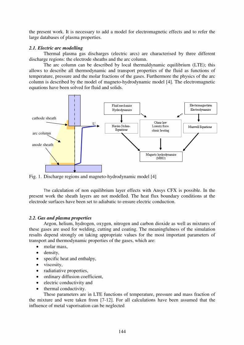
2.1. Electric arc modelling Thermal plasma gas discharges (electric arcs) are characterised by three different
discharge regions: the electrode sheaths and the arc column. The arc column can be described by local thermaldynamic equilibrium (LTE); this
allows to describe all thermodynamic and transport properties of the fluid as functions of temperature, pressure and the molar fractions of the gases. Furthermore the physics of the arc column is described by the model of magneto-hydrodynamic model [4]. The electromagnetic equations have been solved for fluid and solids.
Fig. 1. Discharge regions and magneto-hydrodynamic model [4]
The calculation of non equilibrium layer effects with Ansys CFX is possible. In the present work the sheath layers are not modelled. The heat flux boundary conditions at the electrode surfaces have been set to adiabatic to ensure electric conduction.
2.2. Gas and plasma properties Argon, helium, hydrogen, oxygen, nitrogen and carbon dioxide as well as mixtures of
these gases are used for welding, cutting and coating. The meaningfulness of the simulation results depend strongly on taking appropriate values for the most important parameters of transport and thermodynamic properties of the gases, which are:
• molar mass, • density, • specific heat and enthalpy, • viscosity, • radiatiative properties, • ordinary diffusion coefficient, • electric conductivity and • thermal conductivity.
These parameters are in LTE functions of temperature, pressure and mass fraction of the mixture and were taken from [7-12]. For all calculations have been assumed that the influence of metal vaporisation can be neglected
cathode sheath
arc column
anode sheath
U

145
Thermodynamic and radiation properties of gas mixtures have been calculated by interpolation with molar fraction weighting, transport properties by interpolation with mass fraction weighting. Especially for mixtures with helium or hydrogen this can differ to the calculated results of Murphy [7-10] since interaction between gases is neglected.
Spez. Wärme von Plasmagasen
0.00E+00
5.00E+03
1.00E+04
1.50E+04
2.00E+04
2.50E+04
3.00E+04
3.50E+04
30
0
30
00
57
00
84
00
111
00
138
00
165
00
192
00
219
00
246
00
273
00
300
00
Temperatur [K]
sp
ez.
Wä
rme
[J
/kg
/K]
Argon Sickstoff Sauerstoff Luft
Fig. 2. Specific heat capacity of different gases as function of the temperature at 1 atm pressure
State of the art is the characterisation of the plasma properties as function of temperature (300 -30.000 K) and its chemical composition. For the electric arc and plasma column calculation in plasma cutting torch the plasma properties have to be described up to pressures of 10 bar.
3. Simulation results
The subject of the present paper is the calculation of plasma torches and their
improvement. In the following the results of special simulation tasks will be presented.
3.1. Characterisation of plasma jet arc welding
The results of the calculations are presented in this section for arcs in pure argon at 1 bar. The distance between the copper plasma nozzle and the work piece is 10 mm. The calculated arc with a current of 100 A, 0.3 l/min argon plasma gas flow and 10 l/min shielding gas flow is presented in figure 3. The large column dimension above the work piece comes from the absence of electrode sheaths.
Because of the high number of nonlinearly coupled process parameters the cause-and-effect chains of plasma arcs and the welding seam are complex and hard to describe experimental. One aim of simulation is to describe the relation of welding current, the used process gases and their flow rates. The electric current density and the velocity head characterise diameter and depth of the weldpool and decide about kerfs and keyhole formation.

146
0,0E+00
5,0E+05
1,0E+06
1,5E+06
2,0E+06
2,5E+06
3,0E+06
0 50 100 150I [A]
ima
x [
A/m
²]
0
1000
2000
3000
4000
5000
6000
pm
ax [
Pa
]
PG 0.2 [l/min]
PG 0.4 [l/min]
PG 0.6 [l/min]
Fig. 3. Calculated plasma flow and temperature (left), electric current density and pressure at work piece surface (right) for a plasma welding torch 3.2. Shielding gas influence on plasma jet
For arc welding mixtures of argon and helium, nitrogen and active gases are used. For plasma arc welding combinations of argon and helium with low concentrations of nitrogen especial for the shielding gas are thinkable. Because of the arc ignition and cathode abrasion pure argon is always used as plasma gas.
Because of the plasma jet intake shielding gases have a decisive influence on the plasma jet properties. Calculation of plasma jets with argon plasma gas and pure helium shielding gas determines higher temperatures and a flatter flow profile, figure 4. This gives higher energy densities and lower pressures above the work piece and the ability for fast welding of thin worksheets without unwanted holes.
Fig. 4. Calculated plasma flow and temperature for shielding gases pure argon (left) and pure helium (right) 3.3. Gas shield optimisation for plasma powder coating
Contamination of atmosphere gases in arc welding processes leads to unwanted instabilities of the arc process and to oxidations of welding seam and work piece. Atmosphere gases are the reason for unwanted black powder fall out on and near the weld seam in plasma powder coating.
The reason for oxygen contaminations are the turbulences and the strong gas intake into to the plasma jet direct below the plasma gas nozzle. By using Ansys CFX the design of the shielding gas nozzle has been improved, figure 5.
The simulation results have been transferred to torch fabrication.

147
Fig. 4. Improving the gas shield by plasma arc welding 4. Validation of simulation results
To verify the numerical results, PIV measurements of shielding gas flow and spectral selective arc photographics have been used. 4.1. PIV measurement
The modified PIV setup enables flow measurements of shield gas or plasma in electric arcs. The radiation of the electric arc is masked out at the investigated intensities. The smooth and sufficient particle dosage leads to clear vector graphics, which are computed by correlating the pictures.
The averaged flow fields demonstrate a good agreement with simulation results. 4.1. Spectral selective arc photographics
The special radiation lines of elements in the electric arc and their excitation and ionisation states can be used for the validation of the calculated shape of the plasma column, excited elements and the ionisation state. Pictures with spectrally selective interference filters allow much more predictions as broadband filters. Fig 5 shows the validation of simulation results by comparing the line radiation of atomic and ionised argon.
Fig. 5. Measured strength of line radiation of atomic and ionised argon (left) compared to numerical results (right).
before optimised
Argon
I Argon II
1
2
3
1
2
3
148
Conclusions
The commercial CFD Software Ansys CFX has been used for the numerical simulation of electric arcs of plasma torches as they are used for welding, cutting and coating of metals. The effects of electromagnetism in the fluid and the solids and their interaction with the gases have been solved additionally. The temperature and pressure dependent properties of the process gases have been taken into account.
The simulation results have been used to improve the understanding of plasma jet arc welding and for reengineering different plasma torches. The process simulation of plasma arc welding can be used to improve the welding process.
The validation of the numerical results is indispensable. The numerical results are in good agreement with PIV measurement and line radiation photographs.
References [1] MAECKER, H.: Plasmaströmungen im Lichtbogen infolge eigenmagnetischer Kompression Zeitschrift für
Physik, 141, Berlin (1955), S.198-216 [2] SCHELLHASE, M.: Der Schweißlichtbogen ein technologisches Werkzeug. VEB Verlag Technik Berlin,
1985 [3] RIEDER, W.: Plasma und Lichtbogen, Friedrich Vieweg & Sohn Braunschweig, 1967 [4] SPILLE-KOHOFF; A.; Numerische Simulation des ChopArc-Schweißprozesses in ChopArc: MSG-
Lichbogenschweißen für den Ultraleichtbau; Fraunhofer IRB Verlag 2005, ISBN 3-8167-6766-4. [5] SCHRÖDER,G.: Technische Fotographie: Grundlagen und Anwendung und Anwendung in Technik und
Wissenschaft; Würzburg 1981 [6] MURPHY, A.B.; ARUNDELL, C.J.: Transport coefficients of Argon, Nitrogen, Oxygen, Argon-Nitrogen
and Argon- Oxygen Plasmas, Plasma Chemistry and Plasma Processing, Vol. 14 No. 4 1994 [7] MURPHY, A.B.: Transport coefficients of Air, Argon-Air, Nitrogen-Air Oxygen-Air Plasmas. Plasma
Chemistry and Plasma Processing, Vol. 15 No. 2 1995 [8] MURPHY, A.B.: Transport coefficients of Helium and Argon-Helium Plasmas. Transaction of Plasma
Science, Vol. 25 No. 5 1997 [9] MURPHY, A.B.: Transport coefficients of Hydrogen and Argon- Hydrogen Plasma. Chemistry and Plasma
Processing, Vol. 20, No. 3, 2000 [10] BIRD, STEWART, LIGHFOOT: Transport Phenomena. Wiley, London 1960 [11] BAUDER, U.: Radiation from high pressure plasmas, Journal of. Physics, 39 (1969) No.1, pp 148-152 [12] NAGHIZADEH, Y., CRESSAULT, Y, GLEIZES, A.: Net emission coefficient of air thermal plasma ;
Journal of Physics D, Heft 35 (2002), S. 2925 – 2934
Authors Dipl.-Ing. Schnick, M. Department of Joining Engineering and Assembly Technology Faculty of Mechanical Engineering University of Technology Dresden George-Bähr-Straße3c D-01061Dresden, Germany E-mail: [email protected] Tel.: 0049 351 463 34373


![Rosetta Langmuir probe performance - DiVA portal680862/FULLTEXT01.pdf1.3.1 Debye shielding and Debye length Debye shielding [1] is an innate ability of the plasma to shield out local](https://img.dokumen.tips/doc/110x75/60ffba69c4d405429359b4af/rosetta-langmuir-probe-performance-diva-680862fulltext01pdf-131-debye-shielding.jpg)