Embed Size (px)
Citation preview

HAL Id: hal-01374152https://hal.archives-ouvertes.fr/hal-01374152
Submitted on 29 Sep 2016
HAL is a multi-disciplinary open accessarchive for the deposit and dissemination of sci-entific research documents, whether they are pub-lished or not. The documents may come fromteaching and research institutions in France orabroad, or from public or private research centers.
L’archive ouverte pluridisciplinaire HAL, estdestinée au dépôt et à la diffusion de documentsscientifiques de niveau recherche, publiés ou non,émanant des établissements d’enseignement et derecherche français ou étrangers, des laboratoirespublics ou privés.
Simulation of Low Nickel Content Alloys For IndustrialGround Fault Circuit-Breaker Relays
Oualid Messal, Fabien Sixdenier, Laurent Morel, Noël Burais, ThierryWaeckerle
To cite this version:Oualid Messal, Fabien Sixdenier, Laurent Morel, Noël Burais, Thierry Waeckerle. Simulation ofLow Nickel Content Alloys For Industrial Ground Fault Circuit-Breaker Relays. IEEE Transac-tions on Magnetics, Institute of Electrical and Electronics Engineers, 2014, 51 (6), pp.6991580.�10.1109/TMAG.2014.2384004�. �hal-01374152�
> ID: TMAG-14-06-0349 <
1
Abstract— The aim of this paper is to simulate the
performances of a ground fault circuit-breaker (GFCB) relay with new low nickel content alloys. Indeed, in the construction industry, the materials become more expensive as their nickel content increases. Moreover, the demand for nickel is particularly sensitive to the economic conjuncture. Therefore, an original electromagnetic relay model has been developed and validated in different working conditions (current amplitude, frequency, temperature). A dedicated magnetic characterization of materials is needed, using basically a usual and industrial GFCB relay for reference and design data in modeling. First, the magnetic model of the relay is built and checked against experimental data. The simulation may predict the tripping current threshold of the relay. On the other hand, new low nickel content alloys for relay parts are studied in this framework, thanks to the developed model. The effect of temperature on the magnetic properties of the candidate materials and the electrical performances of the virtual relays is presented. The results, analysis, and conclusions are given. Finally, a first attempt to predict the economic gain made with a change of material is made.
Index Terms— AC circuit- breaker, Dynamic hysteresis, Eddy currents, FeNiCr alloys, Optimization, Temperature.
I. INTRODUCTION HE PROTECTION of persons and domestic or professional appliances against electric shocks must be ensured in
conformity with standards. The IEC60479 standard [1] introduces the effects of the AC current of a frequency 50 Hz on human beings and livestock. In particular, the threshold of ventricular fibrillation increases with frequency (f). One can see in Fig. 1, that the tripping factor (tripping current at the frequency f over the tripping current at the rated frequency of 50 Hz) increases versus frequency according to an exponential curve. The waveform of the current for the given frequencies is sinusoidal. In this respect, manufacturers have developed ground fault circuit-breakers (GFCB) that are compatible with this threshold (limit curve) and its frequency variation. They ensure that the thresholds of the protection devices remain below the ventricular fibrillation curve defined in the standard IEC60479 for each frequency.
A GFCB [2] usually falls into three parts: the differential current sensor, the electronic circuit, and the highly sensitive
Corresponding author: O. Messal ([email protected]). Digital Object Identifier inserted by IEEE
electromagnetic relay, the latter being the framework of this paper. In order to be effective, the relay parts require both high magnetic force (i.e., high magnetic saturation JS) and low energy consumption (i.e., high dynamic relative permeability µr, low coercive field Hc) to trip the breaker under the effect of small electrical fault (a few tenth of mA). The Fe–48%Ni alloy (Supra50) meets these requirements, providing Js = 1.6 T, µr ≈ 120000 and 3 < Hc < 4 A/m after a specific heat treatment. Its temperature stability is very good as the Curie point (Tc) is around 450 °C, far from room temperature (RT). Due to the massive magnetic circuit (1 mm depth), a lot of eddy currents can occur in the magnetic circuit in dynamic regimes. These eddy currents reduce the Fcoil force (see section II). This means that the needed current amplitude has to increase in order to have a sufficient force to make the relay trip. If engineers want to build a model to predict a correct behavior of the relay, eddy currents that can occur in the magnetic circuit have to be taken into account.
Moreover, engineers would like to virtually test the relay's potential behavior with a magnetic circuit made of another material. This last material should realize a compromise between an affordable economic price and good performances. Besides its usual Supra50 (Fe–48%Ni) grades, Aperam [3] develop several FeNiCrCu [4], [5] near 30%Ni (wt) and Invar alloys (36%Ni), as a new material family providing both reduced nickel content, reduced remanent induction Br, higher dynamics (with an electrical resistivity 80 < ρel < 100 µΩ.cm) keeping good DC magnetic properties (Hc ≈ 3 – 10 A/m,
Simulation of Low Nickel Content Alloys For Industrial Ground Fault Circuit-Breaker Relays
Oualid Messal1, Fabien Sixdenier1, Laurent Morel1, Noël Burais1 and Thierry Waeckerlé2
1Université de Lyon, Université Lyon 1, CNRS UMR 5005 AMPERE, 43, Bld du 11 Novembre 1918, Villeurbanne, F69622, France
2Aperam Research Center, Imphy, F58160, France
T
101 102 103 1040
5
10
15
20
25
Frequency (Hz)
I trip(f)
/ I tri
p(50
Hz)
LimitA type IDAC type IDVigirex RH328A
Fig. 1. Variation of the ventricular fibrillation threshold (as per IEC 60479-2) and thresholds of various RCDs set on 30 mA, as a function of frequency (the figure is plotted from data given in [2]).

> ID: TMAG-14-06-0349 <
2
µr ≈ 20000). However, these alloys present two main drawbacks toward this application: their Js is lower than the Supra50’s one (e.g., lower magnetic force) and they do not ensure the same temperature stability (their Tc is lower) at the operating temperatures of the relay [-25, 85 °C]. Thus, changes in their characteristics must be anticipated.
This work deals with the study of the ability of these new low nickel FeNi alloys, designed as a potentially less expensive solution compared to the Supra50. Based on [6], the original approach has been extended to take into account temperature, well adapted to the dynamical behavior description of high sensitivity electromagnetic relay.
In the next sections, we have first carried out an analytical study of the relay in order to analyze qualitatively its operation. This study is based on very simplistic assumptions. However, it helps us to evaluate the nature of the encountered phenomena and clarify our needs in terms of data. It is limited to the linear regime. In the next step, a short recall of the modeling approach of the relay and the dynamic behavior of the material is made. Then, once the model is established, the modeling approach is validated against experimental measurements. The relay model is subsequently used to simulate what would be its behavior with other magnetic alloys at room temperature (RT) and at 85 °C. Finally, a first attempt to predict the economic gain made with a change of magnetic materials is made.
II. OPERATING PRINCIPLE OF THE HIGH-SENSITIVITY ELECTROMAGNETIC RELAY
The relay magnetic circuit (Fig. 2) is composed of an armature (or core), a permanent magnet, and a mobile part in rotation around one of the core leg end where a spring is attached in order to facilitate such movement. The magnet’s force FMagnet is used here to counterbalance the force FSpring of the spring, such as the mobile part closes the magnetic circuit when there is no electrical defect (situation FMagnet > FSpring). The appearance of a leakage current induces an e.m.f. across the terminals of the secondary coil, which supplies the relay. During a favorable current half-period, the flux generated in the magnetic circuit formed by the closed relay is of opposite sign to the flux produced by the magnet: then a new force Fcoil is added to the spring’s one and results in the relay opening (situation Fcoil + FSpring > FMagnet). The operating principle is illustrated in Fig. 2 below.
A. Simplified Analytical Approach of the Frequency Behavior of the Relay Tripping Current
The magnet biases the relay magnetic circuit (mean length, L) to a magnetic polarization level Jp, causing the magnet force FMagnet = Jp
2.S/2µ0). The design and the air gaps are performed in such a way that the magnet polarization Jp is high to create a high enough magnetic force for a magnetic circuit section as small as possible (FeNi cost). But, Jp should not be too high to avoid saturating the material because we also need a high differential permeability µrdiff around the polarization point Jp (see below). In practice, Jp is of the order of 0.8 T.
When there is no electrical defect, FMagnet > FSpring (equilibrium position). Indeed, in practice, each produced relay is set according to a precise amount ∆F= FMagnet – FSpring. The imbalance is introduced by a 3rd force Fcoil coming from the relay coil (number of turns N, field Hcoil), fed by the current I stemming from the electrical fault detection torus. Once Fcoil =∆F, the balance is broken and at this moment, the current I in the coil is the minimum tripping current Itrip of the relay. Let us recall that if e denotes the thickness of the relay material, the skin effect is considered negligible when δ ≥ e/2. If we call ΔJ the variation of the polarization in the magnetic circuit under the effect of the bias field of the magnet Hp around Jp(Hp), we have in a very crude model: If δ < e/2 :
B ≈ J = (2δ / e) ⋅ ΔJ(Jp ) (1) If δ ≥ e/2 :
B ≈ J = ΔJ (2)
In practice, the skin effect is not negligible, so, we focus on this case. Considering ΔJ(Hcoil) quasi-linear around a polarization point of the magnet (Fig. 3 of the Supra50 alloy):
ΔJ Jp( ) = µ0µrdiff Hcoil (3)
We deduce that:
B ≈ 2δeµ0µrdiff Hcoil ≈
2e
2ρµω
µ0µrdiff Hcoil (4)
And according to the Ampere’s theorem:
Hcoil =NItripL
(5)
The expression of B becomes:
B =2N µ0
π eLρµrdiff
itripf
(6)
The relay tripping occurs when:
S N
Flux due to the magnet Flux caused by the favorable period of the ground fault current
S N
Fig. 2. Operating principle of the relay.

> ID: TMAG-14-06-0349 <
3
ΔF = Cte = Fcoil =B2S2µ0
(7)
Whence
B = 2µ0ΔFS
=2N µ0
π eLρµrdiff
Itripf
(8)
Thus:
Itrip =π eL
2N µ0 ρµrdiff
2µ0ΔFS
f (9)
We deduce that the relay tripping current is independent of
frequency when δ ≥ e/2 (when the skin effect is negligible) and it is given as a function of f when δ < e/2. The expression of the tripping current in Eq. (9) reproduces qualitatively the same frequency behavior as in Fig. 1. This relationship is sufficiently interesting to evaluate the influence of each characteristic (e, N, ρ, µrdiff, S, ∆F) on the tripping current; however, it does not enable an accurate prevision of the relay dynamic behavior. Indeed, this study is based on very simplistic assumptions (constant section of the magnetic circuit of the relay, witch is not the case in industrial GFCB, ΔJ(Hcoil) linear…). Besides, we have no data concerning the ∆F term. It is not always either well defined or well quantified.
III. RELAY AND MATERIAL MODELING PROTOCOL
A. Relay Geometry and Magnetic Equivalent Circuit Fig. 4 shows a photograph of the investigated relay and
Fig. 5 shows the scheme of the geometry and the adopted magnetic circuit topology. The device would be modeled by flux tubes instead of finite elements (FE) given the complexity of the problem, the number of unknowns (section II-C), the long computation time with FE, and the necessity of accurate dynamical description taking into account eddy currents.
Fig. 4 shows three kinds of flux tubes: air-gap flux tubes, a magnet flux tube and other magnetic flux tubes accurately representing the dynamic behavior of the soft magnetic relay parts. The geometric flux tubes parameters are their
dimensions (length, section, depth) and parameters that can describe the magnetic behavior of each flux tube. Each flux tube constitutes a “magnetic circuit component” that must be linked to other magnetic or electrical circuit components. This association fulfills the nodes law and the Ampère’s theorem obtained by analogy between magnetic and electric circuits [6]. The coupling variables are dφ dt and H.l (where φ = magnetic flux, H = excitation field on the surface of the flux tube, l = mean length of the tube, Hj.lj= Nk.ik = k-th MMF source). The tools used for simulation are Matlab and Simulink with the SimPowerSystems Blockset toolbox.
The magnet properties (Br, µr) are the essential data, which define the relay tripping conditions. Besides, the major criteria are the dimensions of the air gaps and the number of turns. The leakage flux is supposedly negligible when the mobile part closes the circuit (which is the case for our study).
B. Soft Magnetic Material Modeling In each soft ferromagnetic part (armature, pole, and mobile
part) a dynamic model that takes into account the eddy currents that can occur in the magnetic circuit is implemented. The dynamic model is called the ”Diffusion and Wall Motion” (DWM) model. The main assumptions of the model are:
• the study domain is a rectangular sheet where edge effects are neglected. • the magnetic field is supposed to be unidirectional (along the length of the sheet). • the material is isotropic and its electrical conductivity σel is homogeneous. It takes into account the skin effect developed in the
material and it comes from the magnetic field diffusion
0
50000
100000
150000
200000
0 0,5 1
µ rdi
ff
B(T)
Jp(H magnet polarization)
sine generated by the fault current in the relay coil around the bias point of the magnet (Jp)
Fig. 3. Differential permeability of the soft magnetic material constituting the relay (the Supra50 alloy)
7
4 3 2
6 5
1
9
10
Mobile part 1 Mobile part 2
Pole2 Pole1
Air gap3 Air gap1
Armature1 Armature2
Air
gap2
M
agne
t
Magnétic circuit
Mag
net
Mobile part
Coi
l
Coil 8
Fig. 5. Scheme of the geometry of the relay (left) and its MEC (right).
0 ! 1 ! !2 ! 3 ! ! 4 ! 5!! Fig. 4. The investigated GFCB relay produced and marketed by Schneider Electric [7] (the unit of the ruler is in cm).

> ID: TMAG-14-06-0349 <
4
equation reduced to a 1D formulation. Due to the symmetry of the system, this equation is solved by using the Finite Difference (FD) method on the half- thickness (d/2) of the sheet cross section. The FD system formulation leads to a nonlinear algebraic system that has to be solved. This system contains as many equations as the number of spatial discretization nodes of the studied domain. This model uses a static law Hstat(B) or B(Hstat). Neglecting static hysteresis, we have considered the an-hysteretic curve determined from a measured major quasi-static loop at 0.1 Hz. The DWM model is accurate at high frequencies (see Fig. 6). The dynamic model parameters are identified from measurements performed at 2 kHz using the simplex method [10]. The parameter values are then used to simulate the dynamic behavior at different frequencies below 2 kHz with very good accuracy (for example, see the simulation at 300 Hz in Fig.6-b). More details of this model can be found in [9].
C. Experimental Measurements and Relay Model Validation
In order to validate the developed relay model, experiments have been performed on the demonstrator device for different frequencies under sine current excitation. The residual current device for which tripping is ensured, according to the IEC 6100812 international standard [11], allows the application of slowly rising intended currents, as shown in Fig. 7 (blue curve). The relay is fed with a sine current source until tripping. The excitation coil is supplied with a programmable excitation current (different frequencies). The waveforms of the current (i(t)) and the voltage of the relay coil (u(t)) are recorded on an acquisition board. When the tripping relay occurs, the flux in the air gaps falls suddenly and a transitional phase is sharply marked and the phase shift between u(t) and i(t) becomes very low (see Fig. 7). The ratio umax/imax of the period just before the tripping is used to define Ztrip (even if
the voltage waveform is not sinusoidal), for each frequency. In order to correctly simulate the electromagnetic relay,
some unknowns have to be determined with the help of the experiments. The magnet properties (Br, µr), the number of turns of the coil, and the three air-gaps lengths are optimized using the simplex method. The objective function to minimize is the quadratic error between the simulated and measured Ztrip. Values of the parameters that minimizes the objective function are reported in Table I.
With the values mentioned in Table I, the measured and simulated Ztrip curves versus frequency at RT are shown in Fig. 8.
−300 −200 −100 0 100 200 300−1.5
−1
−0.5
0
0.5
1
1.5
H(A/m)
B(T)
Partie descendantePartie ascendanteCourbe anhystérétique
!
Descending curve Ascending curve Average anhysteretic curve
a) An-hysteretic curve used in dynamic modeling just below.
−300 −200 −100 0 100 200 300
−1.5
−1
−0.5
0
0.5
1
1.5
H(A/m)
B(T)
Simulation(DWM)Mesure
−300 −200 −100 0 100 200 300
−0.2
0
0.2
0.4
0.6
0.8
1
1.2
H(A/m)
B(T)
Simulation(DWM)Mesure
!
Measure Measure
b) Dynamic hysteresis loops in the Supra50 alloy at RT at f = 300 Hz (left) and f = 2 kHz (right).
Fig. 6. Dynamic behavior modeling of the Supra50 alloy.
0
50
100
150
200
250
300
350
10 100 1000 10000
Impe
danc
e Z
trip
(Ω
)"
Frequency (Hz)"
Measure"Simulation"
Fig. 8. Impedance vs frequency at room temperature
TABLE I OPTIMIZED PARAMETERS
Number of turns
Air-gap1 (µm)
Air-gap2 (µm)
Air-gap3 (µm)
Br
(T) µr
508 15.52 0.108 15.52 0.72 3.9
0
50
100
150
200
250
300
350
10 100 1000 10000
Impe
danc
e Z
trip
(Ω )"
Frequency (Hz)"
Measure"Simulation"
0
50
100
150
200
250
300
350
400
10 100 1000 10000
Impe
danc
e Z
[ I =
1m
A]
(Ω )"
Frequency (Hz)"
Measure"Simulation"
êZoom
-2
-1,5
-1
-0,5
0
0,5
1
1,5
2
-20
-15
-10
-5
0
5
10
15
20
0,12 0,13 0,14 0,15 0,16 0,17 0,18
Volta
ge (V
)!
Cur
rent
(mA
)
Time (s)!
Relay open Relay closed Tripping
Fig. 7. Measured current and voltage waveforms at 50 Hz with a slowly rising current and zoom on the tripping conditions at room temperature.
> ID: TMAG-14-06-0349 <
5
As it can be seen in Fig. 8, the measured and simulated Ztrip are in good agreement. This model will now be used to simulate virtual relays with a magnetic circuit made with different alloys than the Supra50.
IV. NEW LOW NICKEL CONTENT INVAR-TYPE FE-NI-CR-CU ALLOYS: BRIEF PRESENTATION
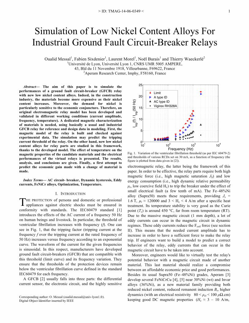
In the construction industry, the higher nickel content of alloys makes them more expensive. In this regard, it should be noted that the demand for nickel is particularly sensitive to the economic conjuncture (see Fig.9).
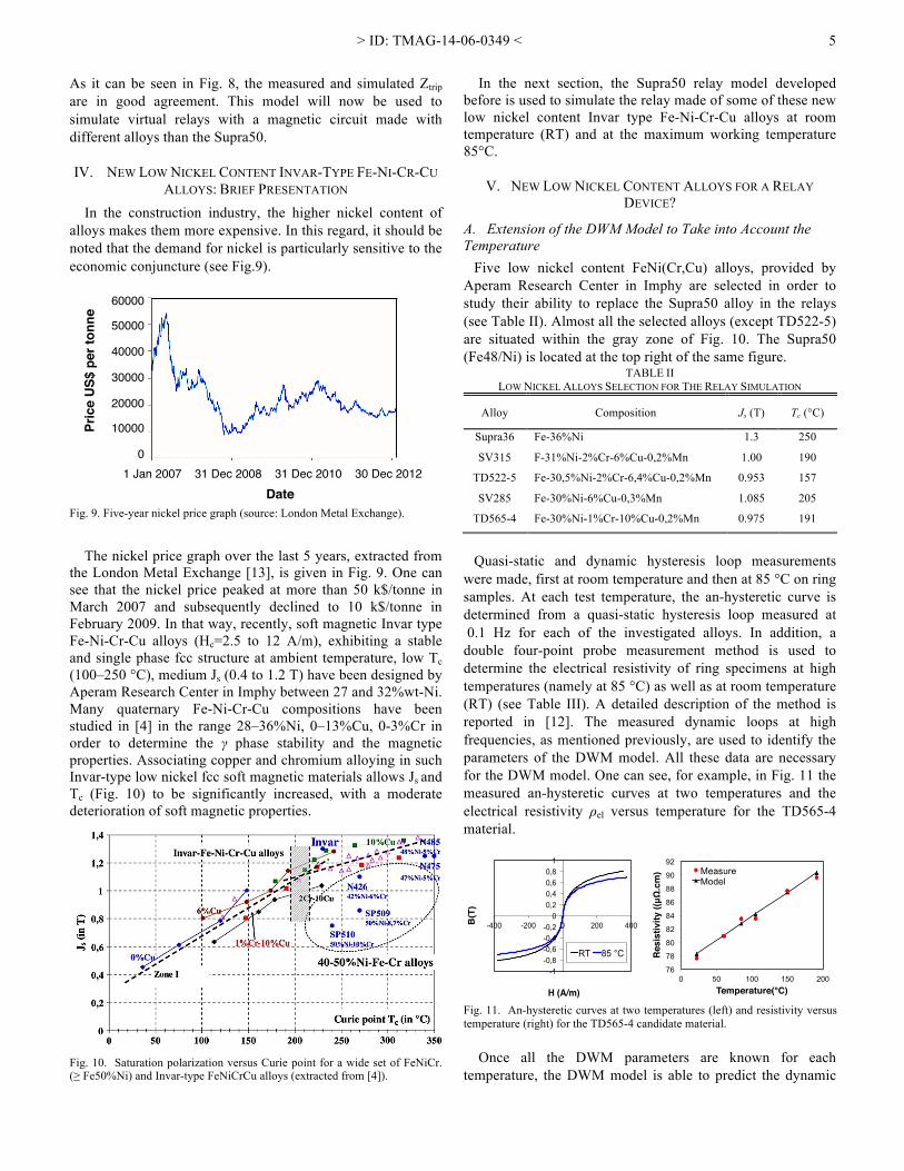
The nickel price graph over the last 5 years, extracted from the London Metal Exchange [13], is given in Fig. 9. One can see that the nickel price peaked at more than 50 k$/tonne in March 2007 and subsequently declined to 10 k$/tonne in February 2009. In that way, recently, soft magnetic Invar type Fe-Ni-Cr-Cu alloys (Hc=2.5 to 12 A/m), exhibiting a stable and single phase fcc structure at ambient temperature, low Tc (100–250 °C), medium Js (0.4 to 1.2 T) have been designed by Aperam Research Center in Imphy between 27 and 32%wt-Ni. Many quaternary Fe-Ni-Cr-Cu compositions have been studied in [4] in the range 28–36%Ni, 0–13%Cu, 0-3%Cr in order to determine the γ phase stability and the magnetic properties. Associating copper and chromium alloying in such Invar-type low nickel fcc soft magnetic materials allows Js and Tc (Fig. 10) to be significantly increased, with a moderate deterioration of soft magnetic properties.
In the next section, the Supra50 relay model developed before is used to simulate the relay made of some of these new low nickel content Invar type Fe-Ni-Cr-Cu alloys at room temperature (RT) and at the maximum working temperature 85°C.
V. NEW LOW NICKEL CONTENT ALLOYS FOR A RELAY DEVICE?
A. Extension of the DWM Model to Take into Account the Temperature
Five low nickel content FeNi(Cr,Cu) alloys, provided by Aperam Research Center in Imphy are selected in order to study their ability to replace the Supra50 alloy in the relays (see Table II). Almost all the selected alloys (except TD522-5) are situated within the gray zone of Fig. 10. The Supra50 (Fe48/Ni) is located at the top right of the same figure.
TABLE II LOW NICKEL ALLOYS SELECTION FOR THE RELAY SIMULATION
Alloy Composition Js (T) Tc (°C)
Supra36 Fe-36%Ni 1.3 250
SV315 F-31%Ni-2%Cr-6%Cu-0,2%Mn 1.00 190
TD522-5 Fe-30,5%Ni-2%Cr-6,4%Cu-0,2%Mn 0.953 157
SV285 Fe-30%Ni-6%Cu-0,3%Mn 1.085 205
TD565-4 Fe-30%Ni-1%Cr-10%Cu-0,2%Mn 0.975 191
Quasi-static and dynamic hysteresis loop measurements
were made, first at room temperature and then at 85 °C on ring samples. At each test temperature, the an-hysteretic curve is determined from a quasi-static hysteresis loop measured at 0.1 Hz for each of the investigated alloys. In addition, a double four-point probe measurement method is used to determine the electrical resistivity of ring specimens at high temperatures (namely at 85 °C) as well as at room temperature (RT) (see Table III). A detailed description of the method is reported in [12]. The measured dynamic loops at high frequencies, as mentioned previously, are used to identify the parameters of the DWM model. All these data are necessary for the DWM model. One can see, for example, in Fig. 11 the measured an-hysteretic curves at two temperatures and the electrical resistivity ρel versus temperature for the TD565-4 material.
Once all the DWM parameters are known for each temperature, the DWM model is able to predict the dynamic
Fig. 10. Saturation polarization versus Curie point for a wide set of FeNiCr. (≥ Fe50%Ni) and Invar-type FeNiCrCu alloys (extracted from [4]).
-1 -0,8 -0,6 -0,4 -0,2
0 0,2 0,4 0,6 0,8
1
-400 -200 0 200 400 B(T
)!
H (A/m)!
RT 85 °C
76
78
80
82
84
86
88
90
92
0 50 100 150 200
Res
istiv
ity ((μΩ
.cm
)#
Temperature(°C)#
Mesaure Model
eas
Fig. 11. An-hysteretic curves at two temperatures (left) and resistivity versus temperature (right) for the TD565-4 candidate material.
60000!!
50000!!
40000!!
30000!!
20000!!
10000!!
0!1 Jan 2007 31 Dec 2008 31 Dec 2010 30 Dec 2012!
Pric
e U
S$ p
er to
nne!
Date! Fig. 9. Five-year nickel price graph (source: London Metal Exchange).

> ID: TMAG-14-06-0349 <
6
behavior at different temperatures. As an example, Fig. 12 illustrates the measured and simulated loops for the TD565-4 candidate material for f = 200 Hz and f = 2 kHz at RT and at 85 °C. One can see that the magnetic behavior has changed. The saturation induction is a bit lower and the loop is thinner at 85 °C than at RT. In each case, the DWM model is in good agreement with the measurements.
B. Tripping Criterion In order to predict the overall behavior of the electro-
magnetic relay built with the candidate materials, a tripping criterion is defined. When a candidate material is introduced in the model, the magnetic permeability of the material is not the same as the Supra50’s one. This will change the reluctance of the magnetic circuit, the electrical impedance, and consequently the relay tripping current value. To study the tripping current, let us begin with a simplified scheme displaying the different forces acting on the mobile part of the relay (see Fig. 13).
The relay tripping occurs when the magnetic torque, Γmag acting on the mobile part is lower than the spring torque. However, the value of the spring torque is unknown. Avoid- ing a direct difficult measurement of its stiffness, we chose another method to predict the tripping current without the knowledge of the torque spring magnitude. Starting from the tripping current data measured at various frequencies in the demonstrator relay (made of Supra50), the corresponding magnetic torque exerted on the moving part may be calculated at each tripping current value in the whole frequency range. This torque will be called ”the reference magnetic torque in tripping conditions.”
In the next step of calculation applied on a candidate alloy, at each test frequency, we determine the current value which allows the same torque as the Supra50 relay solution does, under the same dynamical solicitation (see Fig. 14).
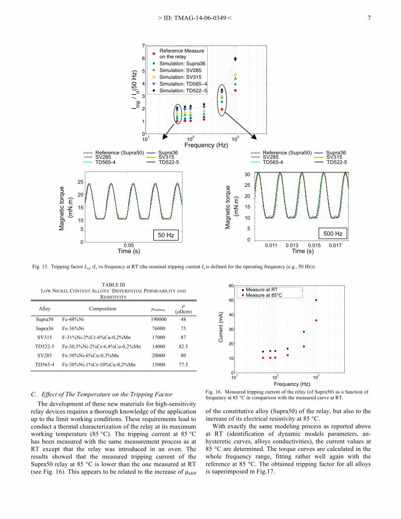
As an example, Fig. 15 shows the 50 and 500 Hz typical magnetic torque curves of the Supra50 relay in tripping conditions at room temperature and the simulated torque curves for the virtual new alloy relays. There is rather good agreement between all the torque curves. The excitation current levels necessary to obtain identical values as the reference magnetic torque in tripping conditions reflect the tripping of the virtual relays constructed from each candidate alloy. Thus, we determine the tripping current of a candidate material relay. The tripping factors Itrip/In as functions of fre- quency, for each of the investigated alloys, are superimposed in Fig. 15. As mentioned before, (9) gives such an assessment, but it remains essentially of a qualitative nature. However, the developed model accurately predicts this variation with the true elements of the relay.
It seems that there is a close connection between the differential permeability, µrdiff of the alloy and the tripping current value of the relay. Table III shows the maximum differential permeability µrdiff_max and the electrical resistivity ρel of the new low nickel content alloys in comparison with the usual Supra50. One can see that as µrdiff_max increases, the tripping current decreases. It should be emphasized that the analytical law in (9) confirms this analysis. It reveals a good inverse relationship between Itrip and µrdiff.
Relay M
odel
Supra50
(Itrip , f)� (I *trip , f)�
Candidate material
Magnetic torque in tripping conditions (Γ )
Torque Γ *
YES
Γ = Γ * NO
Fig. 14. Method to determine the tripping current for candidate alloys.
FPole1 FMagnet
d1
d2 d3
k x FPole2
Γ "
r"
FSpring
Fig. 13. Forces acting on the mobile part of the relay.
−400 −300 −200 −100 0 100 200 300 400−1
−0.8
−0.6
−0.4
−0.2
0
0.2
0.4
0.6
0.8
1
H(A/m)
B(T)
Simulation (DWM) at RTMeasure at RTSimulation (DWM) at 85 °CMeasure at 85 °C
a) f=200 Hz
−400 −300 −200 −100 0 100 200 300 400−0.4
−0.3
−0.2
−0.1
0
0.1
0.2
0.3
0.4
0.5
0.6
H(A/m)
B(T)
Simulation(DWM)at RTMeasure at RTSimulation(DWM) at 85 °CMeasure at 85 °C
b) f=2kHz
Fig. 12. Measured and simulated loops for the TD565-4 candidate material at f=200 Hz at RT and at 85 °C.
> ID: TMAG-14-06-0349 <
7
TABLE III
LOW NICKEL CONTENT ALLOYS ' DIFFERENTIAL PERMEABILITY AND RESISTIVITY
Alloy Composition µrdiffmax ρ
(µΩcm) Supra50 Fe-48%Ni 190000 48
Supra36 Fe-36%Ni 76000 75
SV315 F-31%Ni-2%Cr-6%Cu-0,2%Mn 17000 87
TD522-5 Fe-30,5%Ni-2%Cr-6,4%Cu-0,2%Mn 14000 82.5
SV285 Fe-30%Ni-6%Cu-0,3%Mn 20000 80
TD565-4 Fe-30%Ni-1%Cr-10%Cu-0,2%Mn 15000 77.5
C. Effect of The Temperature on the Tripping Factor The development of these new materials for high-sensitivity
relay devices requires a thorough knowledge of the application up to the limit working conditions. These requirements lead to conduct a thermal characterization of the relay at its maximum working temperature (85 °C). The tripping current at 85 °C has been measured with the same measurement process as at RT except that the relay was introduced in an oven. The results showed that the measured tripping current of the Supra50 relay at 85 °C is lower than the one measured at RT (see Fig. 16). This appears to be related to the increase of µrdiff
of the constitutive alloy (Supra50) of the relay, but also to the increase of its electrical resistivity at 85 °C.
With exactly the same modeling process as reported above at RT (identification of dynamic models parameters, an-hysteretic curves, alloys conductivities), the current values at 85 °C are determined. The torque curves are calculated in the whole frequency range, fitting rather well again with the reference at 85 °C. The obtained tripping factor for all alloys is superimposed in Fig.17.
!101 102 1030
1
2
3
4
5
6
7
Frequency (Hz)I tri
p / I n(5
0 H
z)
Reference Measureon the relaySimulation: Supra36Simulation: SV285Simulation: SV315Simulation: TD565−4Simulation: TD522−5
Reference (Supra50) Supra36 SV285 SV315 TD565-4 TD522-5 !
Reference (Supra50) Supra36 SV285 SV315 TD565-4 TD522-5
0,05
0
5
10
15
20
Temps (s)
Cou
ple
mag
nétiq
ue (m
N.m
)
Référence (Supra50)Supra36SV285SV315TD565−4TD522−5
!
25
20
15
10
5
0
Mag
netic
torq
ue
(mN
.m)
������0.05
Time (s)
0.011 0.013 0.015 0.0170
5
10
15
20
30
40
Temps (s)C
ouple
magnétiq
ue (
mN
.m)
Référence (Supra50) Supra36 SV285 SV315 TD556−4 TD522−5
!
30
25
20
15
10
5
0 �������
Mag
netic
torq
ue
(mN
.m)
0.011 0.013 0.015 0.017 Time (s)
Fig. 15. Tripping factor Itrip /In vs frequency at RT (the nominal tripping current In is defined for the operating frequency (e.g., 50 Hz)).
101 102 1030
10
20
30
40
50
60
Fréquence (Hz)
Cou
rant
(mA)
Mesure à température ambianteMesure à 85°C
!
Measure at RT Measure at 85°C
Cur
rent
(mA
)
Frequency (Hz) Fig. 16. Measured tripping current of the relay (of Supra50) as a function of frequency at 85 °C in comparison with the measured curve at RT.
> ID: TMAG-14-06-0349 <
8
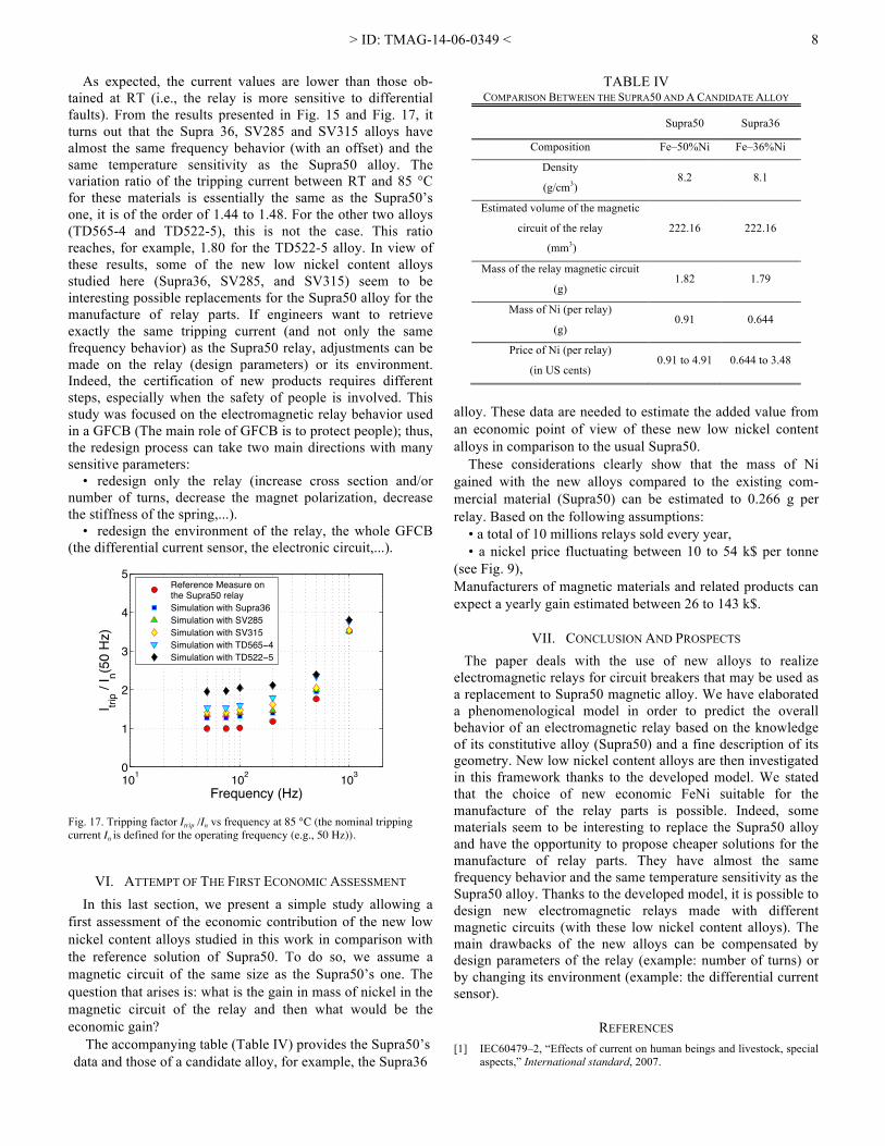
As expected, the current values are lower than those ob- tained at RT (i.e., the relay is more sensitive to differential faults). From the results presented in Fig. 15 and Fig. 17, it turns out that the Supra 36, SV285 and SV315 alloys have almost the same frequency behavior (with an offset) and the same temperature sensitivity as the Supra50 alloy. The variation ratio of the tripping current between RT and 85 °C for these materials is essentially the same as the Supra50’s one, it is of the order of 1.44 to 1.48. For the other two alloys (TD565-4 and TD522-5), this is not the case. This ratio reaches, for example, 1.80 for the TD522-5 alloy. In view of these results, some of the new low nickel content alloys studied here (Supra36, SV285, and SV315) seem to be interesting possible replacements for the Supra50 alloy for the manufacture of relay parts. If engineers want to retrieve exactly the same tripping current (and not only the same frequency behavior) as the Supra50 relay, adjustments can be made on the relay (design parameters) or its environment. Indeed, the certification of new products requires different steps, especially when the safety of people is involved. This study was focused on the electromagnetic relay behavior used in a GFCB (The main role of GFCB is to protect people); thus, the redesign process can take two main directions with many sensitive parameters:
• redesign only the relay (increase cross section and/or number of turns, decrease the magnet polarization, decrease the stiffness of the spring,...).
• redesign the environment of the relay, the whole GFCB (the differential current sensor, the electronic circuit,...).
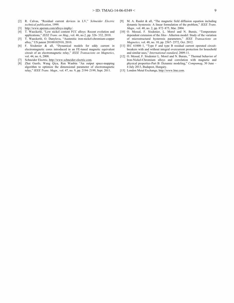
VI. ATTEMPT OF THE FIRST ECONOMIC ASSESSMENT In this last section, we present a simple study allowing a
first assessment of the economic contribution of the new low nickel content alloys studied in this work in comparison with the reference solution of Supra50. To do so, we assume a magnetic circuit of the same size as the Supra50’s one. The question that arises is: what is the gain in mass of nickel in the magnetic circuit of the relay and then what would be the economic gain?
The accompanying table (Table IV) provides the Supra50’s data and those of a candidate alloy, for example, the Supra36
TABLE IV COMPARISON BETWEEN THE SUPRA50 AND A CANDIDATE ALLOY
Supra50 Supra36
Composition Fe–50%Ni Fe–36%Ni
Density
(g/cm3) 8.2 8.1
Estimated volume of the magnetic
circuit of the relay
(mm3)
222.16 222.16
Mass of the relay magnetic circuit
(g) 1.82 1.79
Mass of Ni (per relay)
(g) 0.91 0.644
Price of Ni (per relay)
(in US cents) 0.91 to 4.91 0.644 to 3.48
alloy. These data are needed to estimate the added value from an economic point of view of these new low nickel content alloys in comparison to the usual Supra50.
These considerations clearly show that the mass of Ni gained with the new alloys compared to the existing com- mercial material (Supra50) can be estimated to 0.266 g per relay. Based on the following assumptions:
• a total of 10 millions relays sold every year, • a nickel price fluctuating between 10 to 54 k$ per tonne
(see Fig. 9), Manufacturers of magnetic materials and related products can expect a yearly gain estimated between 26 to 143 k$.
VII. CONCLUSION AND PROSPECTS The paper deals with the use of new alloys to realize
electromagnetic relays for circuit breakers that may be used as a replacement to Supra50 magnetic alloy. We have elaborated a phenomenological model in order to predict the overall behavior of an electromagnetic relay based on the knowledge of its constitutive alloy (Supra50) and a fine description of its geometry. New low nickel content alloys are then investigated in this framework thanks to the developed model. We stated that the choice of new economic FeNi suitable for the manufacture of the relay parts is possible. Indeed, some materials seem to be interesting to replace the Supra50 alloy and have the opportunity to propose cheaper solutions for the manufacture of relay parts. They have almost the same frequency behavior and the same temperature sensitivity as the Supra50 alloy. Thanks to the developed model, it is possible to design new electromagnetic relays made with different magnetic circuits (with these low nickel content alloys). The main drawbacks of the new alloys can be compensated by design parameters of the relay (example: number of turns) or by changing its environment (example: the differential current sensor).
REFERENCES [1] IEC60479–2, “Effects of current on human beings and livestock, special
aspects,” International standard, 2007.
101 102 1030
1
2
3
4
5
Frequency (Hz)
I trip /
I n(50
Hz)
Reference Measure onthe Supra50 relaySimulation with Supra36Simulation with SV285Simulation with SV315Simulation with TD565−4Simulation with TD522−5
Fig. 17. Tripping factor Itrip /In vs frequency at 85 °C (the nominal tripping current In is defined for the operating frequency (e.g., 50 Hz)).
> ID: TMAG-14-06-0349 <
9
[2] R. Calvas, “Residual current devices in LV,” Schneider Electric technical publication, 1999.
[3] http://www.aperam.com/alloys-imphy/. [4] T. Waeckerlé, “Low nickel content FCC alloys: Recent evolution and
applications,” IEEE Trans. on Mag., vol. 46, no.2, pp. 326- 332, 2010. [5] T. Waeckerlé, O. Danylova, “Austenitic iron-nickel-chromium-copper
alloy,” US patent 20100102910, 2010. [6] F. Sixdenier & all, “Dynamical models for eddy current in
electromagnetic cores introduced in an FE-tuned magnetic equivalent circuit of an electromagnetic relay,” IEEE Transacions on Magnetics, vol. 44, no. 6, 2008.
[7] Schneider Electric, http://www.schneider-electric.com. [8] Zhai Guofo, Wang Qiya, Ren Wanbin “An output space-mapping
algorithm to optimize the dimensional parameter of electromagnetic relay,” IEEE Trans. Magn., vol. 47, no. 9, pp. 2194–2199, Sept. 2011.
[9] M. A. Raulet & all, “The magnetic field diffusion equation including dynamic hysteresis: A linear formulation of the problem,” IEEE Trans. Magn., vol. 40, no. 2, pp. 872–875, Mar. 2004.
[10] O. Messal, F. Sixdenier, L. Morel and N. Burais, “Temperature dependent extension of the Jiles– Atherton model: Study of the variation of microstructural hysteresis parameters,” IEEE Transactions on Magnetics, vol. 48, no. 10, pp. 2567- 2572, Oct. 2012.
[11] IEC 61008–1, “Type F and type B residual current operated circuit-breakers with and without integral overcurrent protection for household and similar uses,” International standard, 2009-11.
[12] O. Messal, F. Sixdenier L. Morel and N. Burais, ” Thermal behavior of Iron-Nickel-Chromium alloys and correlation with magnetic and physical properties-Part B: Dynamic modeling,” Compumag, 30 June – 4 July 2013, Budapest, Hungary.
[13] London Metal Exchange, http://www.lme.com.